EP3498114B1 - Electronic smoking device with liquid duct - Google Patents
Electronic smoking device with liquid ductDownload PDFInfo
- Publication number
- EP3498114B1 EP3498114B1EP17208252.1AEP17208252AEP3498114B1EP 3498114 B1EP3498114 B1EP 3498114B1EP 17208252 AEP17208252 AEP 17208252AEP 3498114 B1EP3498114 B1EP 3498114B1
- Authority
- EP
- European Patent Office
- Prior art keywords
- liquid reservoir
- liquid
- electronic smoking
- smoking device
- docking
- Prior art date
- Legal status (The legal status is an assumption and is not a legal conclusion. Google has not performed a legal analysis and makes no representation as to the accuracy of the status listed.)
- Active
Links
- 239000007788liquidSubstances0.000titleclaimsdescription177
- 230000000391smoking effectEffects0.000titleclaimsdescription30
- 238000003032molecular dockingMethods0.000claimsdescription71
- 238000007789sealingMethods0.000claimsdescription41
- 239000003571electronic cigaretteSubstances0.000description35
- 238000010438heat treatmentMethods0.000description14
- 239000000443aerosolSubstances0.000description9
- 210000000078clawAnatomy0.000description4
- 230000004913activationEffects0.000description3
- 239000000463materialSubstances0.000description3
- 230000009471actionEffects0.000description2
- 230000008859changeEffects0.000description2
- 235000019504cigarettesNutrition0.000description2
- 239000000835fiberSubstances0.000description2
- 229910052751metalInorganic materials0.000description2
- 239000002184metalSubstances0.000description2
- 239000004033plasticSubstances0.000description2
- 230000001007puffing effectEffects0.000description2
- 230000004044responseEffects0.000description2
- 229910000831SteelInorganic materials0.000description1
- 229910052782aluminiumInorganic materials0.000description1
- XAGFODPZIPBFFR-UHFFFAOYSA-NaluminiumChemical compound[Al]XAGFODPZIPBFFR-UHFFFAOYSA-N0.000description1
- POIUWJQBRNEFGX-XAMSXPGMSA-NcathelicidinChemical compoundC([C@@H](C(=O)N[C@@H](CCCNC(N)=N)C(=O)N[C@@H](CCCCN)C(=O)N[C@@H](CO)C(=O)N[C@@H](CCCCN)C(=O)N[C@@H](CCC(O)=O)C(=O)N[C@@H](CCCCN)C(=O)N[C@@H]([C@@H](C)CC)C(=O)NCC(=O)N[C@@H](CCCCN)C(=O)N[C@@H](CCC(O)=O)C(=O)N[C@@H](CC=1C=CC=CC=1)C(=O)N[C@@H](CCCCN)C(=O)N[C@@H](CCCNC(N)=N)C(=O)N[C@@H]([C@@H](C)CC)C(=O)N[C@@H](C(C)C)C(=O)N[C@@H](CCC(N)=O)C(=O)N[C@@H](CCCNC(N)=N)C(=O)N[C@@H]([C@@H](C)CC)C(=O)N[C@@H](CCCCN)C(=O)N[C@@H](CC(O)=O)C(=O)N[C@@H](CC=1C=CC=CC=1)C(=O)N[C@@H](CC(C)C)C(=O)N[C@@H](CCCNC(N)=N)C(=O)N[C@@H](CC(N)=O)C(=O)N[C@@H](CC(C)C)C(=O)N[C@@H](C(C)C)C(=O)N1[C@@H](CCC1)C(=O)N[C@@H](CCCNC(N)=N)C(=O)N[C@@H]([C@@H](C)O)C(=O)N[C@@H](CCC(O)=O)C(=O)N[C@@H](CO)C(O)=O)NC(=O)[C@H](CC=1C=CC=CC=1)NC(=O)[C@H](CC(O)=O)NC(=O)CNC(=O)[C@H](CC(C)C)NC(=O)[C@@H](N)CC(C)C)C1=CC=CC=C1POIUWJQBRNEFGX-XAMSXPGMSA-N0.000description1
- 239000000919ceramicSubstances0.000description1
- 238000001514detection methodMethods0.000description1
- 239000000428dustSubstances0.000description1
- 238000001704evaporationMethods0.000description1
- 239000011152fibreglassSubstances0.000description1
- 239000012528membraneSubstances0.000description1
- 239000011148porous materialSubstances0.000description1
- 239000007921spraySubstances0.000description1
- 239000010959steelSubstances0.000description1
Images


Classifications
- A—HUMAN NECESSITIES
- A24—TOBACCO; CIGARS; CIGARETTES; SIMULATED SMOKING DEVICES; SMOKERS' REQUISITES
- A24F—SMOKERS' REQUISITES; MATCH BOXES; SIMULATED SMOKING DEVICES
- A24F40/00—Electrically operated smoking devices; Component parts thereof; Manufacture thereof; Maintenance or testing thereof; Charging means specially adapted therefor
- A24F40/40—Constructional details, e.g. connection of cartridges and battery parts
- A24F40/48—Fluid transfer means, e.g. pumps
- A24F40/485—Valves; Apertures
- A—HUMAN NECESSITIES
- A24—TOBACCO; CIGARS; CIGARETTES; SIMULATED SMOKING DEVICES; SMOKERS' REQUISITES
- A24F—SMOKERS' REQUISITES; MATCH BOXES; SIMULATED SMOKING DEVICES
- A24F15/00—Receptacles or boxes specially adapted for cigars, cigarettes, simulated smoking devices or cigarettes therefor
- A24F15/01—Receptacles or boxes specially adapted for cigars, cigarettes, simulated smoking devices or cigarettes therefor specially adapted for simulated smoking devices or cigarettes therefor
- A24F15/015—Receptacles or boxes specially adapted for cigars, cigarettes, simulated smoking devices or cigarettes therefor specially adapted for simulated smoking devices or cigarettes therefor with means for refilling of liquid inhalable precursors
- A—HUMAN NECESSITIES
- A24—TOBACCO; CIGARS; CIGARETTES; SIMULATED SMOKING DEVICES; SMOKERS' REQUISITES
- A24F—SMOKERS' REQUISITES; MATCH BOXES; SIMULATED SMOKING DEVICES
- A24F40/00—Electrically operated smoking devices; Component parts thereof; Manufacture thereof; Maintenance or testing thereof; Charging means specially adapted therefor
- A24F40/10—Devices using liquid inhalable precursors
- A—HUMAN NECESSITIES
- A61—MEDICAL OR VETERINARY SCIENCE; HYGIENE
- A61M—DEVICES FOR INTRODUCING MEDIA INTO, OR ONTO, THE BODY; DEVICES FOR TRANSDUCING BODY MEDIA OR FOR TAKING MEDIA FROM THE BODY; DEVICES FOR PRODUCING OR ENDING SLEEP OR STUPOR
- A61M2209/00—Ancillary equipment
- A61M2209/04—Tools for specific apparatus
- A61M2209/045—Tools for specific apparatus for filling, e.g. for filling reservoirs
Definitions
- EP 3143884 A2discloses an electronic smoking device comprising a power supply portion and an atomizer/liquid reservoir portion comprising a refillable liquid reservoir adapted for storing a liquid, and an atomizer operable when connected to the power supply to atomize liquid stored in the liquid reservoir.
- the atomizer/liquid reservoir portioncomprises a liquid filling channel and an air outlet channel at least partially separate from the liquid filling channel.
- the liquid ductopens into the refillable liquid reservoir at a distance to the docking valve, and a valve for releasing gas from the refillable liquid reservoir when refilling the refillable liquid reservoir, the valve comprising a flexible sealing element and an essentially rigid counter sealing element formed by an outer side wall section of the central passage.
- Figure 4shows the exemplary embodiment of figures 2 and 3 , wherein the refill bottle 148 is in a docked position D after the refill bottle 148 has been moved along a movement path for docking MD, which essentially extends perpendicularly to the longitudinal direction L.
- Figures 8 and 9show the liquid reservoir 134 of the atomizer/liquid reservoir portion 114.
- a central passage 132 of the atomizer/liquid reservoir portion 114extends through the liquid reservoir 134 against the longitudinal direction L in order to transport atomized liquid towards an air inhalation port 136 of the atomizer/liquid reservoir portion 114, the air inhalation port 136 opening into the mouthpiece cap 140.
- the liquid reservoir 134has a cylindrical cross-section and extends along the longitudinal direction L.
- the central passage 132is arranged in the liquid reservoir 134, such that the liquid reservoir 134 surrounds or encompasses the central passage 132 at least sectionwise or even completely perpendicular to the longitudinal direction L.
- the flexible sealing element 182can be an umbrella seal or can comprise at least one flexible sealing tongue or lip with a fixed end in the longitudinal direction L and a free end against the longitudinal direction L.
- the closing element 184In the refill position R the closing element 184 is arranged at a distance to the flexible sealing element 182 against the longitudinal direction L. In the vaping position V of the mouthpiece cap 140, the closing element 184 rests against the flexible sealing element 182 and holds the flexible element 182 against the rigid counter sealing element 186.
Landscapes
- Catching Or Destruction (AREA)
Description
- The present invention relates generally to electronic smoking devices and in particular electronic cigarettes. The present invention in particular relates to electronic smoking devices having a refillable liquid reservoir.
- An electronic smoking device, such as an electronic cigarette (e-cigarette), typically has a housing accommodating an electric power source (e.g. a single use or rechargeable battery, electrical plug, or other power source), and an electrically operable atomizer. The atomizer vaporizes or atomizes liquid supplied from a reservoir and provides vaporized or atomized liquid as an aerosol. Control electronics control the activation of the atomizer. In some electronic cigarettes, an airflow sensor is provided within the electronic smoking device, which detects a user puffing on the device (e.g., by sensing an under-pressure or an air flow pattern through the device). The airflow sensor indicates or signals the puff to the control electronics to power up the device and generate vapor. In other e-cigarettes, a switch is used to power up the e-cigarette to generate a puff of vapor.
- An electronic smoking device can be adapted to allow refilling a liquid reservoir.
EP 3143884 A2 discloses an electronic smoking device comprising a power supply portion and an atomizer/liquid reservoir portion comprising a refillable liquid reservoir adapted for storing a liquid, and an atomizer operable when connected to the power supply to atomize liquid stored in the liquid reservoir. The atomizer/liquid reservoir portion comprises a liquid filling channel and an air outlet channel at least partially separate from the liquid filling channel.- In accordance with one aspect of the present invention, there is provided an electronic smoking device that comprises a power supply portion comprising a power supply, and an atomizer/liquid reservoir portion. The atomizer/liquid reservoir portion comprises a refillable liquid reservoir adapted for storing liquid, an atomizer operable when connected to the power supply to atomize liquid stored in the liquid reservoir, and a central passage that is adapted to conduct atomized liquid, the central passage extending through the refillable liquid reservoir. The atomizer/liquid reservoir portion comprises a docking valve for docking a source of liquid to be stored in the liquid reservoir, a liquid duct that is adapted to receive liquid from the docking valve. The liquid duct opens into the refillable liquid reservoir at a distance to the docking valve, and a valve for releasing gas from the refillable liquid reservoir when refilling the refillable liquid reservoir, the valve comprising a flexible sealing element and an essentially rigid counter sealing element formed by an outer side wall section of the central passage.
- The characteristics, features and advantages of this invention and the manner in which they are obtained as described above, will become more apparent and be more clearly understood in connection with the following description of exemplary embodiments, which are explained with reference to the accompanying drawings.
- In the drawings, same element numbers indicate same elements in each of the views:
- Figure 1
- is a schematic cross-sectional illustration of an exemplary e-cigarette;
- Figures 2 to 7
- show an exemplary embodiment of an e-cigarette in ready-for-use and in refill states;
- Figures 8 to 10
- depict the exemplary embodiment of
figures 2 to 7 in a schematic cross-sectional view; - Figure 11
- illustrates the exemplary embodiment of
figures 2 to 10 in another schematic cross-sectional view; and - Figure 12
- illustrates the exemplary embodiment of
figures 2 to 11 in another schematic cross-sectional view. - Throughout the following, an electronic smoking device will be exemplarily described with reference to an e-cigarette. As is shown in
Figure 1 , ane-cigarette 10 typically has a housing comprising a cylindrical hollow tube having anend cap 16. The cylindrical hollow tube may be a single-piece or a multiple-piece tube. InFigure 1 , the cylindrical hollow tube is shown as a two-piece structure having apower supply portion 12 and an atomizer/liquid reservoir portion 14. Together thepower supply portion 12 and the atomizer/liquid reservoir portion 14 form a cylindrical tube which can be approximately the same size and shape as a conventional cigarette, typically about 100 mm with a 7.5 mm diameter, although lengths may range from 70 to 150 or 180 mm, and diameters from 5 to 28 mm. - The
power supply portion 12 and atomizer/liquid reservoir portion 14 are typically made of metal, e.g. steel or aluminum, or of hardwearing plastic and act together with theend cap 16 to provide a housing to contain the components of thee-cigarette 10. Thepower supply portion 12 and an atomizer/liquid reservoir portion 14 may be configured to fit together by a friction push-fit, a snap-fit, or a bayonet attachment, magnetic-fit, or screw threads. Theend cap 16 is provided at the front end of thepower supply portion 12. Theend cap 16 may be made from translucent plastic or other translucent material to allow a light-emitting diode (LED) 20 positioned near the end cap to emit light through the end cap. The end cap can be made of metal or other materials that do not allow light to pass. - An air inlet may be provided in the end cap, at the edge of the inlet next to the cylindrical hollow tube, anywhere along the length of the cylindrical hollow tube, or at the connection of the
power supply portion 12 and the atomizer/liquid reservoir portion 14.Figure 1 shows a pair ofair inlets 38 provided at the intersection between thepower supply portion 12 and the atomizer/liquid reservoir portion 14. - A power supply, preferably a
battery 18, anLED 20,control electronics 22 and optionally anairflow sensor 24 are provided within the cylindrical hollow tubepower supply portion 12. Thebattery 18 is electrically connected to thecontrol electronics 22, which are electrically connected to theLED 20 and theairflow sensor 24. In this example, theLED 20 is at the front end of thepower supply portion 12, adjacent to theend cap 16 and thecontrol electronics 22 andairflow sensor 24 are provided in the central cavity at the other end of thebattery 18 adjacent to the atomizer/liquid reservoir portion 14. - The
airflow sensor 24 acts as a puff detector, detecting a user puffing or sucking on the atomizer/liquid reservoir portion 14 of thee-cigarette 10. Theairflow sensor 24 can be any suitable sensor for detecting changes in airflow or air pressure, such as a microphone switch including a deformable membrane which is caused to move by variations in air pressure. Alternatively, the sensor may be a Hall element or an electro-mechanical sensor. - The
control electronics 22 are also connected to anatomizer 26. In the example shown, theatomizer 26 includes aheating coil 28 which is wrapped around awick 30 extending across acentral passage 32 of the atomizer/liquid reservoir portion 14. Thecoil 28 may be positioned anywhere in theatomizer 26 and may be transverse or parallel to theliquid reservoir 34. Thewick 30 andheating coil 28 do not completely block thecentral passage 32. Rather an air gap is provided on either side of theheating coil 28 enabling air to flow past theheating coil 28 and thewick 30. The atomizer may alternatively use other forms of heating elements, such as ceramic heaters, or fiber or mesh material heaters. Nonresistance heating elements such as sonic, piezo and jet spray may also be used in the atomizer in place of the heating coil. - The
central passage 32 is surrounded by a cylindricalliquid reservoir 34 with the ends of thewick 30 abutting or extending into theliquid reservoir 34. Thewick 30 may be a porous material such as a bundle of fiberglass fibers, with liquid in theliquid reservoir 34 drawn by capillary action from the ends of thewick 30 towards the central portion of thewick 30 encircled by theheating coil 28. - The
liquid reservoir 34 may alternatively include wadding soaked in liquid which encircles thecentral passage 32 with the ends of thewick 30 abutting the wadding. In other examples, theliquid reservoir 34 may comprise a toroidal cavity arranged to be filled with liquid and with the ends of thewick 30 extending into the toroidal cavity. - An
air inhalation port 36 is provided at the back end of the atomizer/liquid reservoir portion 14 remote from theend cap 16. Theinhalation port 36 may be formed from the cylindrical hollow tube atomizer/liquid reservoir portion 14 or maybe formed in an end cap. - In use, a user sucks on the
e-cigarette 10. This causes air to be drawn into thee-cigarette 10 via one or more air inlets, such asair inlets 38, and to be drawn through thecentral passage 32 towards theair inhalation port 36. The change in air pressure which arises is detected by theairflow sensor 24, which generates an electrical signal that is passed to thecontrol electronics 22. In response to the signal, thecontrol electronics 22 activate theheating coil 28, which causes liquid present in thewick 30 to be vaporized, creating an aerosol (which may comprise gaseous and liquid components) within thecentral passage 32. As the user continues to suck on thee-cigarette 10, this aerosol is drawn through thecentral passage 32 and inhaled by the user. At the same time, thecontrol electronics 22 also activate theLED 20 causing theLED 20 to light up which is visible via thetranslucent end cap 16 mimicking the appearance of a glowing ember at the end of a conventional cigarette. As liquid present in thewick 30 is converted into an aerosol, more liquid is drawn into thewick 30 from theliquid reservoir 34 by capillary action and thus is available to be converted into an aerosol through subsequent activation of theheating coil 28. - Some e-cigarettes are intended to be disposable and the electric power in the
battery 18 is intended to be sufficient to vaporize the liquid contained within theliquid reservoir 34, after which thee-cigarette 10 is thrown away. In other examples thebattery 18 is rechargeable and theliquid reservoir 34 is refillable. In the cases where theliquid reservoir 34 is a toroidal cavity, this may be achieved by refilling theliquid reservoir 34 via a refill port. In other examples the atomizer/liquid reservoir portion 14 of the e-cigarette 10 is detachable from thepower supply portion 12 and a new atomizer/liquid reservoir portion 14 can be fitted with anew liquid reservoir 34 thereby replenishing the supply of liquid. In some cases, replacing theliquid reservoir 34 may involve replacement of theheating coil 28 and thewick 30 along with the replacement of theliquid reservoir 34. A replaceable unit comprising theatomizer 26 and theliquid reservoir 34 is called a cartomizer. - The
new liquid reservoir 34 may be in the form of a cartridge having acentral passage 32 through which a user inhales aerosol. In other examples, aerosol may flow around the exterior of thecartridge 32 to anair inhalation port 36. - Of course, in addition to the above description of the structure and function of a
typical e-cigarette 10, variations also exist. For example, theLED 20 may be omitted. Theairflow sensor 24 may be placed adjacent to theend cap 16 rather than in the middle of the e-cigarette. Theairflow sensor 24 may be replaced with a switch which enables a user to activate the e-cigarette manually rather than in response to the detection of a change in air flow or air pressure. Different types of atomizers may be used. Thus, for example, the atomizer may have a heating coil in a cavity in the interior of a porous body soaked in liquid. In this design aerosol is generated by evaporating the liquid within the porous body either by activation of the coil heating the porous body or alternatively by the heated air passing over or through the porous body. Alternatively, the atomizer may use a piezoelectric atomizer to create an aerosol either in combination or in the absence of a heater. Figures 2 to 7 show an embodiment of the e-cigarette 100 in ready-to-use and refill states. Thee-cigarette 100 comprises thepower supply portion 112 and the atomizer/liquid reservoir portion 114.- Optionally, the
power supply portion 112 is removable from the atomizer/liquid reservoir portion 114 or vice versa. Figure 2 shows the c-cigarette 100 in a ready-to-use state, in which a user of the e-cigarette 100 can use thee-cigarette 100 for vaping, i.e. for inhaling the atomized liquid storable in the atomizer/liquid reservoir portion 114. In the ready-to-use state, amouthpiece cap 140 of thee-cigarette 100 is arranged in its vaping position V, in which themouthpiece cap 140 borders, i.e. directly contacts, the atomizer/liquid reservoir portion 114, such that anouter side 142 of themouthpiece cap 140 forms an essentially continuous surface with anouter side 144 of the atomizer/liquid reservoir portion 114.- The atomizer/
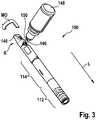
liquid reservoir portion 114 of the exemplary embodiment offigure 2 is arranged between thepower supply portion 112 and themouthpiece cap 140 in a longitudinal direction L of thee-cigarette 100, the longitudinal direction L pointing from themouthpiece cap 140 to thepower supply portion 112. Figure 3 shows the exemplary embodiment offigure 2 in a refill state. In the refill state, themouthpiece cap 140 is arranged in its refill position R. In the refill position R, adocking valve 146 of thee-cigarette 100 for receiving liquid to be stored in the atomizer/liquid reservoir portion 114 is exposed or uncovered by themouthpiece cap 140.- In its refill position R, the
mouthpiece cap 140 is arranged at a distance to its vaping position V at least against the longitudinal direction L of thee-cigarette 100. Hence, in the refill position R, themouthpiece cap 140 is arranged further away from thepower supply portion 112 compared to its vaping position V. - Optionally or additionally, the
mouthpiece cap 140 may be rotated around the longitudinal direction L by a predefined angle compared to its vaping position V. In the exemplary embodiment offigure 3 , themouthpiece cap 140 is arranged further away from thepower supply portion 112 and rotated around the longitudinal direction L with respect to the vaping position V shown infigure 2 , in which themouthpiece cap 140 covers thedocking valve 146, such that dirt or dust is hindered from entering thedocking valve 146. - The arrow MO indicates a possible movement path of the
mouthpiece cap 140 between the refill position R and the vaping position V. - At least in the refill position R and optionally also in the vaping position V, the
mouthpiece cap 140 is captively or undetachably connected to the atomizer/liquid reservoir portion 114, such that themouthpiece cap 140 cannot be lost. - In the exposed or uncovered state of the
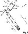
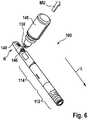
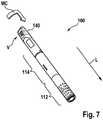
docking valve 146, a source of liquid, exemplarily shown as arefill bottle 148, can dock at thedocking valve 146 in order to refill thee-cigarette 100, in particular the liquid reservoir of thee-cigarette 100. In order to dock therefill bottle 148 with thedocking valve 146, acounter docking valve 150 of therefill bottle 148 can be placed onto or inside of thedocking valve 146, e.g. essentially perpendicular to the longitudinal direction L of thee-cigarette 100. Figure 4 shows the exemplary embodiment offigures 2 and3 , wherein therefill bottle 148 is in a docked position D after therefill bottle 148 has been moved along a movement path for docking MD, which essentially extends perpendicularly to the longitudinal direction L.Figure 5 shows therefill bottle 148 in its docked position D. In order to refill thee-cigarette 100, therefill bottle 148 can be squeezed, e.g. perpendicular the longitudinal direction L. Squeezing therefill bottle 148 means compressing therefill bottle 148, or pressingopposite side walls refill bottle 148 together. In the docked position D, theside walls e-cigarette 100.Figure 6 shows the exemplary embodiment offigures 2 to 5 . In order to separate therefill bottle 148 from thee-cigarette 100, therefill bottle 148 is moved away from thee-cigarette 100 along the movement path for undocking MU. In order to release the connection in between thedocking valve 146 and thecounter docking valve 150, at least the movement along the movement path for undocking MU is sufficient. Optionally, therefill bottle 148 may additionally tilted back and forth perpendicularly to the movement path for undocking MU.Figure 7 shows the exemplary embodiment offigures 2 to 6 . Themouthpiece cap 140 is shown positioned in its vaping position V. The vaping position V may differ from the refill position R along and/or around the longitudinal direction L. In the exemplary embodiment offigure 7 , themouthpiece cap 140 is moved from the refill position R to the vaping position V along the movement path MC, i.e. first around the longitudinal direction L and, then, along the longitudinal direction L.- The exemplary embodiment of the electronic smoking device comprising the
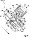
mouthpiece cap 140 and thedocking valve 146 may, as such, be advantages on its own and independent of the further features of the exemplary embodiment mentioned in the following. Figure 8 shows the exemplary embodiment offigures 2 to 7 in a cross-sectional view, wherein the cross-section extends along the longitudinal direction L of thee-cigarette 100.Figure 9 shows an enlarged detail I offigure 8 .Figures 8 and9 show theliquid reservoir 134 of the atomizer/liquid reservoir portion 114. Acentral passage 132 of the atomizer/liquid reservoir portion 114 extends through theliquid reservoir 134 against the longitudinal direction L in order to transport atomized liquid towards anair inhalation port 136 of the atomizer/liquid reservoir portion 114, theair inhalation port 136 opening into themouthpiece cap 140. Theliquid reservoir 134 has a cylindrical cross-section and extends along the longitudinal direction L. Thecentral passage 132 is arranged in theliquid reservoir 134, such that theliquid reservoir 134 surrounds or encompasses thecentral passage 132 at least sectionwise or even completely perpendicular to the longitudinal direction L.- The atomizer/
liquid reservoir portion 114 is formed with aliquid duct 156, that is adapted to the receive liquid from thedocking valve 146 and that opens into theliquid reservoir 134 at a distance A to thedocking valve 146. Theliquid duct 156 essentially extends perpendicularly to the longitudinal direction L. Hence, sections of theliquid reservoir 134, which are arranged at a distance from thedocking valve 146 can receive liquid first when refilling theliquid reservoir 134. Thus, air present in theliquid reservoir 134 before refilling theliquid reservoir 134 can escape at least along a part of theliquid reservoir 134 that is arranged at theliquid duct 156 and/or thedocking valve 146. - The
docking valve 146 is shown with a sealingelement 158 that is pressed into a sealing position, in which thesealing element 158 seals thedocking valve 146. Thedocking valve 146 comprises aresilient element 160 that seeks to press the sealingelement 158 in the sealed position. - For example, the sealing
element 158 has a spherical shape, e.g. the shape of a ball. Theresilient element 160 is e.g. a spring and for example a coil spring. - The
resilient element 160 in particular seeks to press the sealingelement 156 perpendicular to the longitudinal direction L into its sealing position. - In the embodiment shown in
figures 8 and9 , themouthpiece cap 140 is positioned in its refill position R and thecounter docking valve 150 of therefill bottle 148 is docked to thedocking valve 146. Thecounter docking valve 150 presses the sealingelement 158 out of its sealing position against the spring force of theresilient element 160, i.e. essentially perpendicular to the longitudinal direction L. - The
docking valve 146 is adapted to form a snap-fit connection with thecounter docking valve 150 of therefill bottle 148. For example, thedocking valve 146 has a docking section, wherein the docking section comprises a convex- or a concave-shaped cross-section, thereby forming a setback orrecess 162. Thecounter docking valve 150 is adapted to form a snap-fit connection with thedocking valve 146 of the electronic smoking device. Thecounter docking valve 150 for example, compriseselastic latch claws 164 that are arranged around a central axis of thecounter docking valve 150. Thelatch claws 164 are shown curved towards the central axis and are adapted to engage therecess 162 in the docked position D of therefill bottle 148. - The embodiment of the
docking valve 148 forming therecess 162 and thecounter docking valve 150 with theelastic latch claws 164 is advantages on its own and in particular independent of the embodiments discussed previously and in the following. - The
liquid duct 156 opens into theliquid reservoir 134 with anoutlet orifice 166. Theoutlet orifice 166 is arranged at a predetermined distance to a side wall section 168 of theliquid reservoir 134 at which thedocking valve 146 is arranged. For example, theoutlet orifice 166 is arranged closer to aside wall section 170 of theliquid reservoir 134 opposite to the side wall section 168, i.e. opposite to thedocking valve 146, than to thedocking valve 146. In particular, theoutlet orifice 166 opens into a section of theliquid reservoir 134 that is opposite to another section of theliquid reservoir 134 arranged at thedocking valve 146. - Arrow Fl indicates the flow-in path of
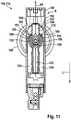
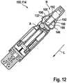
liquid 172 flowing from therefill bottle 148 into theliquid reservoir 134. The other arrow FO indicates a flow-out path of air as it escapes out of theliquid reservoir 134 when refilling the liquid 172. The flow-in path FI begins inside of therefill bottle 148 and extends through thecounter docking valve 150, thedocking valve 146 and through theliquid duct 156 into theliquid reservoir 134. The flow-out path FO extends through a part of theliquid reservoir 134 that surrounds theliquid duct 156 and/or is arrange at thedocking valve 146 against the longitudinal direction L towards theair inhalation port 136. Along theair inhalation port 136, the flow-out path FO extends through themouthpiece cap 140 outside theelectronic smoking device 100. The embodiment of the atomizer/liquid reservoir portion 114 with theliquid duct 156 and optionally with theoutlet orifice 166 is advantages on its own independent of the embodiments previously and in the following. Figure 10 shows the exemplary embodiment offigures 2 to 9 in the cross-sectional view offigures 8 and9 , wherein no refill bottle is docked with thedocking valve 146. The sealingelement 158 seals thedocking valve 146, wherein theresilient element 160 presses the sealingelement 158 against side walls of thedocking valve 146 that delimit aninlet opening 174 of thedocking valve 146.Figure 11 shows the exemplary embodiment offigures 2 to 10 in another cross-sectional view, wherein the cross-section extends along the longitudinal direction L. Thedocking valve 146 points into the drawing plane offigure 11 .- The cross-sectional plane extends along the longitudinal direction L through the
central passage 132. Theliquid duct 156 extends through thecentral passage 132, in particular, through aconvex section 176 of thecentral passage 132. Theconvex section 176 is formed by twopassage sections central passage 132 before and after theliquid duct 156 in the longitudinal direction L. Thepassage sections liquid duct 156 extends essentially perpendicular to the longitudinal direction L. The path of atomized liquid extends through thecentral passage 132 and through thepassage sections - According to the invention, the atomizer/
liquid reservoir portion 114 comprises avalve 181 for releasing gas, e.g. air from theliquid reservoir 134 when refilling theliquid reservoir 134, thevalve 181 comprising aflexible sealing element 182 and essentially rigidcounter sealing element 186 formed by an outerside wall section 183 of thecentral passage 132. - The section of the
central passage 132 that provides for the rigidcounter sealing element 186 has a curved shape. - The atomizer/
liquid reservoir portion 114 comprises at least oneflexible sealing element 182 that rests against the outerside wall section 183 of theconvex section 176 and thereby closes the flow-out path FO. When refilling the atomizer/liquid reservoir portion 114, pressing the liquid out of therefill bottle 148 into theliquid reservoir 134 increases the pressure of air within theliquid reservoir 134. This increased pressure is sufficient in order to replace or deform theflexible sealing element 182, such that air can escape from theliquid reservoir 134 via theflexible sealing element 182 towards themouthpiece cap 140. - The
flexible sealing element 182 can be an umbrella seal or can comprise at least one flexible sealing tongue or lip with a fixed end in the longitudinal direction L and a free end against the longitudinal direction L. - The
mouthpiece cap 140 can comprise at least oneclosing element 184 that forces theflexible sealing element 182 against a rigidcounter sealing element 186 provided by theconvex section 176 and in particular by the outerside wall section 183. The rigidcounter sealing element 186 and theflexible sealing element 182 are shown arranged at a side of theconvex section 176 that faces themouthpiece cap 140. - In the refill position R the
closing element 184 is arranged at a distance to theflexible sealing element 182 against the longitudinal direction L. In the vaping position V of themouthpiece cap 140, theclosing element 184 rests against theflexible sealing element 182 and holds theflexible element 182 against the rigidcounter sealing element 186. - The embodiment of the atomizer/
liquid reservoir portion 114 with theflexible sealing element 182, theclosing element 184 and the rigidcounter sealing element 186 as such is advantages on its own and independent of the embodiments disclosed previously and in the following.Figure 12 shows the exemplary embodiment offigures 2 to 11 in the cross-sectional view offigure 10 . - The
mouthpiece cap 140 is held in the refill position R and/or the vaping position V in a force-fit manner. For example, themouthpiece cap 140 is held in the refill position R or in the vaping position V by a latched connection. Alatch element 188, e.g. a protrusion, is provided by an end of theclosing element 184 perpendicular to the longitudinal direction L, and counter latchelements side wall section 194 of thecentral passage 132. The outerside wall section 194 may be the lateral surface of thecentral passage 132. Thecounter latch element 190 that holds themouthpiece cap 140 in the vaping position V may be provided by a latch protrusion and thecounter latch element 192 that holds themouthpiece cap 140 in the refill position R may be provided by a latch recess or a set back provides by the latch recess or a protrusion. - 10, 100
- electronic smoking device
- 12, 112
- power supply portion
- 14, 114
- atomizer/liquid reservoir portion
- 16
- end cap
- 18
- battery
- 20
- light-emitting diode (LED)
- 22
- control electronics
- 24
- airflow sensor
- 26, 126
- atomizer
- 28
- heating coil
- 30
- wick
- 32, 132
- central passage
- 34, 134
- liquid reservoir
- 36, 136
- air inhalation port
- 38, 138
- air inlets
- 140
- mouthpiece cap
- 142
- outer side of mouthpiece cap
- 144
- outer side of atomizer/liquid reservoir portion
- 146
- docking valve
- 148
- refill bottle
- 150
- counter docking valve
- 152, 154
- side walls of refill bottle
- 156
- liquid duct
- 158
- sealing element
- 160
- resilient element
- 162
- recess
- 164
- elastic latch claws
- 166
- outlet orifice of liquid duct
- 168
- side wall section of liquid reservoir with docking valve
- 170
- side wall section of liquid reservoir opposite to docking valve
- 172
- liquid
- 174
- inlet opening of docking valve
- 176
- convex section of central passage
- 178, 180
- passage section
- 181
- valve
- 182
- flexible sealing element
- 183
- outer side wall section of convex section of central passage
- 184
- closing element
- 186
- rigid counter sealing element
- 188
- latch element
- 190, 192
- counter latch element
- 194
- outer side wall section of central passage with counter latch element
- A
- distance
- AP
- path of atomized liquid
- D
- docked position
- FI
- flow-in path
- FO
- flow-out path
- L
- longitudinal direction
- MC
- movement path from vaping to refill position
- MD
- movement path for docking
- MO
- movement path from refill to vaping position
- MU
- movement path for undocking
- R
- refill position
- V
- vaping position
Claims (14)
- An electronic smoking device (100), comprising:a power supply portion (112) comprising a power supply (18), andan atomizer/liquid reservoir portion (114) comprisinga refillable liquid reservoir (134) adapted for storing liquid (172),an atomizer (26) operable when connected to the power supply (18) to atomize liquid (172) stored in the liquid reservoir (134), anda central passage (132) that is adapted to conduct atomized liquid, the central passage (132) extending through the refillable liquid reservoir (134),wherein the atomizer/liquid reservoir portion (114) comprisesa docking valve (146) for docking a source of liquid (148) to be stored in the liquid reservoir (134),a liquid duct (156) that is adapted to receive liquid (172) from the docking valve (146) and that opens into the refillable liquid reservoir (134) at a predetermined distance (A) to the docking valve (146), anda valve (181) for releasing gas from the refillable liquid reservoir (134) when refilling the refillable liquid reservoir (134), the valve (181) comprising a flexible sealing element (182) and an essentially rigid counter sealing element (186) formed by an outer side wall section (183) of the central passage (132).
- The electronic smoking device (100) according to claim 1, wherein the liquid duct (156) opens into the refillable liquid reservoir (134) with an outlet orifice (166).
- The electronic smoking device (100) according to claim 2, wherein the outlet orifice (166) is arranged closer to a side wall section (170) of the refillable liquid reservoir (134) opposite to the docking valve (146) than to the docking valve (146).
- The electronic smoking device (100) according to claim 1, wherein the section of the central passage (132) that provides for the rigid counter sealing element (186) has a curved shape.
- The electronic smoking device (100) according to claim 1 or 4, wherein the liquid duct (156) extends essentially perpendicular to and through the central passage (132) at a convex section (176) of the central passage (132).
- The electronic smoking device (100) according to any one of claims 1 to 5, wherein the electronic smoking device (100) comprises a mouthpiece cap (140) in communication with an air inhalation port (136) for providing atomized liquid to a user, wherein the mouthpiece cap (140) comprises a refill position (R) and a vaping position (V), wherein in the vaping position (V), the mouthpiece cap (140) is closer to an opposite end of the electronic smoking device (100) than in the refill position (R), and/or wherein in the vaping position (V,) the mouthpiece cap (140) is rotated around a longitudinal axis of the electronic smoking device (100) by a predetermined angle compared to the refill position (R).
- The electronic smoking device (100) according to claim 6, wherein the docking valve (146) is covered by the mouthpiece cap (140) in the vaping position (V), and is accessible when the mouthpiece cap (140) is in the refill position (R).
- The electronic smoking device (100) according to claim 6 or 7, wherein the mouthpiece cap (140) comprises a closing element (184) that forces the flexible sealing element (182) against the rigid counter sealing element (186) when the mouthpiece cap (140) is in the vaping position (V).
- The electronic smoking device (100) according to claim 8, wherein the closing element (184) is arranged at a distance to the flexible sealing element (182) when the mouthpiece cap (140) is in the refill position (R).
- The electronic smoking device (100) according to any one of claims 6 to 9, wherein the mouthpiece cap (140) is held in the refill position (R) and/or in the vaping position (V) in a force-fit manner and/or in a form-fit manner.
- The electronic smoking device (100) according to any one of claims 8 to 9, wherein a latch element (188) of a latch connection holding the mouthpiece cap (140) in the vaping position (V) and/or in the refill position (R) is provided by the closing element (184), and a counter latch element (190, 192) is provided by an outer side wall section (194) of the central passage (132).
- The electronic smoking device (100) according to any one of claims 1 to 11, wherein the docking valve (146) is adapted to form a snap-fit connection with a counter docking valve (150) of a source of liquid.
- The electronic smoking device (100) according to any of claims 1 to 12, wherein the docking valve (146) has a docking section, the docking section comprising a convex or a concave shape.
- An atomizer/liquid reservoir portion (114) comprising:a liquid reservoir (134),an atomizer (26) operable when connected to a power supply (18) for an electronic smoking device (100) to atomize liquid stored in the liquid reservoir (134), anda central passage (132) that is adapted to conduct atomized liquid, the central passage (132) extending through the refillable liquid reservoir (134),wherein the atomizer/liquid reservoir portion (114) comprisesa docking valve (146) for docking a source of liquid (148) to be stored in the liquid reservoir (134),a liquid duct (156) that is adapted to receive liquid (172) from the docking valve (146) and that opens into the refillable liquid reservoir (134) at a predetermined distance (A) to the docking valve (146), anda valve (181) for releasing gas from the refillable liquid reservoir (134) when refilling the refillable liquid reservoir (134), the valve (181) comprising a flexible sealing element (182) and an essentially rigid counter sealing element (186) formed by an outer side wall section (183) of the central passage (132).
Priority Applications (7)
| Application Number | Priority Date | Filing Date | Title |
|---|---|---|---|
| EP17208252.1AEP3498114B1 (en) | 2017-12-18 | 2017-12-18 | Electronic smoking device with liquid duct |
| US16/954,467US11470884B2 (en) | 2017-12-18 | 2018-12-18 | Electronic smoking device with liquid filling valve |
| PCT/EP2018/085500WO2019121684A1 (en) | 2017-12-18 | 2018-12-18 | Electronic smoking device with liquid filling valve |
| CN201880089670.1ACN111770694A (en) | 2017-12-18 | 2018-12-18 | Electronic smoking device with liquid-filled valve |
| CA3085681ACA3085681A1 (en) | 2017-12-18 | 2018-12-18 | Electronic smoking device with liquid filling valve |
| US17/943,742US12274306B2 (en) | 2017-12-18 | 2022-09-13 | Electronic smoking device with liquid filling valve |
| US19/077,855US20250204601A1 (en) | 2017-12-18 | 2025-03-12 | Electronic smoking device with liquid filling valve |
Applications Claiming Priority (1)
| Application Number | Priority Date | Filing Date | Title |
|---|---|---|---|
| EP17208252.1AEP3498114B1 (en) | 2017-12-18 | 2017-12-18 | Electronic smoking device with liquid duct |
Publications (2)
| Publication Number | Publication Date |
|---|---|
| EP3498114A1 EP3498114A1 (en) | 2019-06-19 |
| EP3498114B1true EP3498114B1 (en) | 2021-07-21 |
Family
ID=60673891
Family Applications (1)
| Application Number | Title | Priority Date | Filing Date |
|---|---|---|---|
| EP17208252.1AActiveEP3498114B1 (en) | 2017-12-18 | 2017-12-18 | Electronic smoking device with liquid duct |
Country Status (1)
| Country | Link |
|---|---|
| EP (1) | EP3498114B1 (en) |
Cited By (1)
| Publication number | Priority date | Publication date | Assignee | Title |
|---|---|---|---|---|
| US11464082B2 (en) | 2018-07-31 | 2022-10-04 | Juul Labs, Inc. | Cartridge-based heat not burn vaporizer |
Families Citing this family (3)
| Publication number | Priority date | Publication date | Assignee | Title |
|---|---|---|---|---|
| EP4118987A1 (en)* | 2021-07-15 | 2023-01-18 | Shenzhen Eigate Technology Co., Ltd. | Atomizer |
| US20240415186A1 (en)* | 2021-11-03 | 2024-12-19 | Jt International Sa | An Electronic Cigarette Pod, a Liquid Refill Device and a Refill Assembly Comprising Both |
| CN217826750U (en)* | 2022-05-05 | 2022-11-18 | 深圳麦克韦尔科技有限公司 | Electronic atomization device and atomizer |
Family Cites Families (6)
| Publication number | Priority date | Publication date | Assignee | Title |
|---|---|---|---|---|
| EP3003075B1 (en)* | 2013-06-03 | 2020-01-08 | Old Navigators Limited | Kit for inhaling vaporized substances |
| WO2015027436A1 (en)* | 2013-08-29 | 2015-03-05 | 吉瑞高新科技股份有限公司 | Electronic cigarette |
| GB2524293B (en)* | 2014-03-19 | 2017-12-06 | Kind Consumer Ltd | An inhaler |
| DE202015001439U1 (en)* | 2015-02-24 | 2015-03-18 | German Stil Vapor Kg | The invention relates to a filling valve for an electrically operated inhaler, also referred to as an evaporator or electronic zigartette |
| DE102015217671B4 (en)* | 2015-09-15 | 2020-12-31 | Fontem Holdings 1 B.V. | Device and method for filling an electronic cigarette |
| CN206603250U (en)* | 2017-02-07 | 2017-11-03 | 深圳市艾维普思科技股份有限公司 | Electronic cigarette |
- 2017
- 2017-12-18EPEP17208252.1Apatent/EP3498114B1/enactiveActive
Cited By (1)
| Publication number | Priority date | Publication date | Assignee | Title |
|---|---|---|---|---|
| US11464082B2 (en) | 2018-07-31 | 2022-10-04 | Juul Labs, Inc. | Cartridge-based heat not burn vaporizer |
Also Published As
| Publication number | Publication date |
|---|---|
| EP3498114A1 (en) | 2019-06-19 |
Similar Documents
| Publication | Publication Date | Title |
|---|---|---|
| US12274306B2 (en) | Electronic smoking device with liquid filling valve | |
| US12225931B2 (en) | Electronic smoking device with refillable liquid reservoir | |
| US11064733B2 (en) | Mouth piece of an electronic smoking device having a tempering element | |
| US10945464B2 (en) | Electronic smoking device with a variable-volume liquid reservoir | |
| US11058151B2 (en) | Refill adapter cap for a refill receptacle to refill liquid in an electronic smoking device | |
| US11160306B2 (en) | Electronic smoking device having a pump mechanism | |
| US10792685B2 (en) | Liquid supply for an electronic smoking device | |
| EP3162227B1 (en) | Electronic smoking device, cartomizer and liquid reservoir | |
| EP3155908B1 (en) | Electronic smoking device with adaptable atomizing chamber | |
| EP3498114B1 (en) | Electronic smoking device with liquid duct | |
| GB2539055A (en) | Removable atomizer and electronic smoking device with lateral opening | |
| EP3498113B1 (en) | Electronic smoking device with liquid filling valve |
Legal Events
| Date | Code | Title | Description |
|---|---|---|---|
| PUAI | Public reference made under article 153(3) epc to a published international application that has entered the european phase | Free format text:ORIGINAL CODE: 0009012 | |
| STAA | Information on the status of an ep patent application or granted ep patent | Free format text:STATUS: THE APPLICATION HAS BEEN PUBLISHED | |
| AK | Designated contracting states | Kind code of ref document:A1 Designated state(s):AL AT BE BG CH CY CZ DE DK EE ES FI FR GB GR HR HU IE IS IT LI LT LU LV MC MK MT NL NO PL PT RO RS SE SI SK SM TR | |
| AX | Request for extension of the european patent | Extension state:BA ME | |
| STAA | Information on the status of an ep patent application or granted ep patent | Free format text:STATUS: REQUEST FOR EXAMINATION WAS MADE | |
| 17P | Request for examination filed | Effective date:20191211 | |
| RBV | Designated contracting states (corrected) | Designated state(s):AL AT BE BG CH CY CZ DE DK EE ES FI FR GB GR HR HU IE IS IT LI LT LU LV MC MK MT NL NO PL PT RO RS SE SI SK SM TR | |
| REG | Reference to a national code | Ref country code:DE Ref legal event code:R079 Ref document number:602017042416 Country of ref document:DE Free format text:PREVIOUS MAIN CLASS: A24F0047000000 Ipc:A24F0040485000 | |
| GRAP | Despatch of communication of intention to grant a patent | Free format text:ORIGINAL CODE: EPIDOSNIGR1 | |
| STAA | Information on the status of an ep patent application or granted ep patent | Free format text:STATUS: GRANT OF PATENT IS INTENDED | |
| RIC1 | Information provided on ipc code assigned before grant | Ipc:A24F 40/485 20200101AFI20210408BHEP Ipc:A24F 40/10 20200101ALN20210408BHEP Ipc:A24F 15/015 20200101ALN20210408BHEP | |
| INTG | Intention to grant announced | Effective date:20210506 | |
| RIC1 | Information provided on ipc code assigned before grant | Ipc:A24F 40/485 20200101AFI20210426BHEP Ipc:A24F 40/10 20200101ALN20210426BHEP Ipc:A24F 15/015 20200101ALN20210426BHEP | |
| GRAS | Grant fee paid | Free format text:ORIGINAL CODE: EPIDOSNIGR3 | |
| GRAA | (expected) grant | Free format text:ORIGINAL CODE: 0009210 | |
| STAA | Information on the status of an ep patent application or granted ep patent | Free format text:STATUS: THE PATENT HAS BEEN GRANTED | |
| AK | Designated contracting states | Kind code of ref document:B1 Designated state(s):AL AT BE BG CH CY CZ DE DK EE ES FI FR GB GR HR HU IE IS IT LI LT LU LV MC MK MT NL NO PL PT RO RS SE SI SK SM TR | |
| REG | Reference to a national code | Ref country code:GB Ref legal event code:FG4D | |
| REG | Reference to a national code | Ref country code:CH Ref legal event code:EP | |
| REG | Reference to a national code | Ref country code:DE Ref legal event code:R096 Ref document number:602017042416 Country of ref document:DE | |
| REG | Reference to a national code | Ref country code:AT Ref legal event code:REF Ref document number:1411757 Country of ref document:AT Kind code of ref document:T Effective date:20210815 | |
| REG | Reference to a national code | Ref country code:IE Ref legal event code:FG4D | |
| REG | Reference to a national code | Ref country code:LT Ref legal event code:MG9D | |
| REG | Reference to a national code | Ref country code:NL Ref legal event code:MP Effective date:20210721 | |
| REG | Reference to a national code | Ref country code:AT Ref legal event code:MK05 Ref document number:1411757 Country of ref document:AT Kind code of ref document:T Effective date:20210721 | |
| PG25 | Lapsed in a contracting state [announced via postgrant information from national office to epo] | Ref country code:AT Free format text:LAPSE BECAUSE OF FAILURE TO SUBMIT A TRANSLATION OF THE DESCRIPTION OR TO PAY THE FEE WITHIN THE PRESCRIBED TIME-LIMIT Effective date:20210721 Ref country code:BG Free format text:LAPSE BECAUSE OF FAILURE TO SUBMIT A TRANSLATION OF THE DESCRIPTION OR TO PAY THE FEE WITHIN THE PRESCRIBED TIME-LIMIT Effective date:20211021 Ref country code:LT Free format text:LAPSE BECAUSE OF FAILURE TO SUBMIT A TRANSLATION OF THE DESCRIPTION OR TO PAY THE FEE WITHIN THE PRESCRIBED TIME-LIMIT Effective date:20210721 Ref country code:PT Free format text:LAPSE BECAUSE OF FAILURE TO SUBMIT A TRANSLATION OF THE DESCRIPTION OR TO PAY THE FEE WITHIN THE PRESCRIBED TIME-LIMIT Effective date:20211122 Ref country code:NL Free format text:LAPSE BECAUSE OF FAILURE TO SUBMIT A TRANSLATION OF THE DESCRIPTION OR TO PAY THE FEE WITHIN THE PRESCRIBED TIME-LIMIT Effective date:20210721 Ref country code:NO Free format text:LAPSE BECAUSE OF FAILURE TO SUBMIT A TRANSLATION OF THE DESCRIPTION OR TO PAY THE FEE WITHIN THE PRESCRIBED TIME-LIMIT Effective date:20211021 Ref country code:ES Free format text:LAPSE BECAUSE OF FAILURE TO SUBMIT A TRANSLATION OF THE DESCRIPTION OR TO PAY THE FEE WITHIN THE PRESCRIBED TIME-LIMIT Effective date:20210721 Ref country code:FI Free format text:LAPSE BECAUSE OF FAILURE TO SUBMIT A TRANSLATION OF THE DESCRIPTION OR TO PAY THE FEE WITHIN THE PRESCRIBED TIME-LIMIT Effective date:20210721 Ref country code:SE Free format text:LAPSE BECAUSE OF FAILURE TO SUBMIT A TRANSLATION OF THE DESCRIPTION OR TO PAY THE FEE WITHIN THE PRESCRIBED TIME-LIMIT Effective date:20210721 Ref country code:RS Free format text:LAPSE BECAUSE OF FAILURE TO SUBMIT A TRANSLATION OF THE DESCRIPTION OR TO PAY THE FEE WITHIN THE PRESCRIBED TIME-LIMIT Effective date:20210721 Ref country code:HR Free format text:LAPSE BECAUSE OF FAILURE TO SUBMIT A TRANSLATION OF THE DESCRIPTION OR TO PAY THE FEE WITHIN THE PRESCRIBED TIME-LIMIT Effective date:20210721 | |
| PG25 | Lapsed in a contracting state [announced via postgrant information from national office to epo] | Ref country code:PL Free format text:LAPSE BECAUSE OF FAILURE TO SUBMIT A TRANSLATION OF THE DESCRIPTION OR TO PAY THE FEE WITHIN THE PRESCRIBED TIME-LIMIT Effective date:20210721 Ref country code:LV Free format text:LAPSE BECAUSE OF FAILURE TO SUBMIT A TRANSLATION OF THE DESCRIPTION OR TO PAY THE FEE WITHIN THE PRESCRIBED TIME-LIMIT Effective date:20210721 Ref country code:GR Free format text:LAPSE BECAUSE OF FAILURE TO SUBMIT A TRANSLATION OF THE DESCRIPTION OR TO PAY THE FEE WITHIN THE PRESCRIBED TIME-LIMIT Effective date:20211022 | |
| REG | Reference to a national code | Ref country code:DE Ref legal event code:R097 Ref document number:602017042416 Country of ref document:DE | |
| PG25 | Lapsed in a contracting state [announced via postgrant information from national office to epo] | Ref country code:DK Free format text:LAPSE BECAUSE OF FAILURE TO SUBMIT A TRANSLATION OF THE DESCRIPTION OR TO PAY THE FEE WITHIN THE PRESCRIBED TIME-LIMIT Effective date:20210721 | |
| PLBE | No opposition filed within time limit | Free format text:ORIGINAL CODE: 0009261 | |
| STAA | Information on the status of an ep patent application or granted ep patent | Free format text:STATUS: NO OPPOSITION FILED WITHIN TIME LIMIT | |
| PG25 | Lapsed in a contracting state [announced via postgrant information from national office to epo] | Ref country code:SM Free format text:LAPSE BECAUSE OF FAILURE TO SUBMIT A TRANSLATION OF THE DESCRIPTION OR TO PAY THE FEE WITHIN THE PRESCRIBED TIME-LIMIT Effective date:20210721 Ref country code:SK Free format text:LAPSE BECAUSE OF FAILURE TO SUBMIT A TRANSLATION OF THE DESCRIPTION OR TO PAY THE FEE WITHIN THE PRESCRIBED TIME-LIMIT Effective date:20210721 Ref country code:RO Free format text:LAPSE BECAUSE OF FAILURE TO SUBMIT A TRANSLATION OF THE DESCRIPTION OR TO PAY THE FEE WITHIN THE PRESCRIBED TIME-LIMIT Effective date:20210721 Ref country code:EE Free format text:LAPSE BECAUSE OF FAILURE TO SUBMIT A TRANSLATION OF THE DESCRIPTION OR TO PAY THE FEE WITHIN THE PRESCRIBED TIME-LIMIT Effective date:20210721 Ref country code:CZ Free format text:LAPSE BECAUSE OF FAILURE TO SUBMIT A TRANSLATION OF THE DESCRIPTION OR TO PAY THE FEE WITHIN THE PRESCRIBED TIME-LIMIT Effective date:20210721 Ref country code:AL Free format text:LAPSE BECAUSE OF FAILURE TO SUBMIT A TRANSLATION OF THE DESCRIPTION OR TO PAY THE FEE WITHIN THE PRESCRIBED TIME-LIMIT Effective date:20210721 | |
| 26N | No opposition filed | Effective date:20220422 | |
| PG25 | Lapsed in a contracting state [announced via postgrant information from national office to epo] | Ref country code:MC Free format text:LAPSE BECAUSE OF FAILURE TO SUBMIT A TRANSLATION OF THE DESCRIPTION OR TO PAY THE FEE WITHIN THE PRESCRIBED TIME-LIMIT Effective date:20210721 Ref country code:IT Free format text:LAPSE BECAUSE OF FAILURE TO SUBMIT A TRANSLATION OF THE DESCRIPTION OR TO PAY THE FEE WITHIN THE PRESCRIBED TIME-LIMIT Effective date:20210721 | |
| REG | Reference to a national code | Ref country code:CH Ref legal event code:PL | |
| REG | Reference to a national code | Ref country code:BE Ref legal event code:MM Effective date:20211231 | |
| PG25 | Lapsed in a contracting state [announced via postgrant information from national office to epo] | Ref country code:LU Free format text:LAPSE BECAUSE OF NON-PAYMENT OF DUE FEES Effective date:20211218 Ref country code:IE Free format text:LAPSE BECAUSE OF NON-PAYMENT OF DUE FEES Effective date:20211218 | |
| PG25 | Lapsed in a contracting state [announced via postgrant information from national office to epo] | Ref country code:BE Free format text:LAPSE BECAUSE OF NON-PAYMENT OF DUE FEES Effective date:20211231 | |
| PG25 | Lapsed in a contracting state [announced via postgrant information from national office to epo] | Ref country code:LI Free format text:LAPSE BECAUSE OF NON-PAYMENT OF DUE FEES Effective date:20211231 Ref country code:CH Free format text:LAPSE BECAUSE OF NON-PAYMENT OF DUE FEES Effective date:20211231 | |
| P01 | Opt-out of the competence of the unified patent court (upc) registered | Effective date:20230517 | |
| PG25 | Lapsed in a contracting state [announced via postgrant information from national office to epo] | Ref country code:CY Free format text:LAPSE BECAUSE OF FAILURE TO SUBMIT A TRANSLATION OF THE DESCRIPTION OR TO PAY THE FEE WITHIN THE PRESCRIBED TIME-LIMIT Effective date:20210721 | |
| PG25 | Lapsed in a contracting state [announced via postgrant information from national office to epo] | Ref country code:HU Free format text:LAPSE BECAUSE OF FAILURE TO SUBMIT A TRANSLATION OF THE DESCRIPTION OR TO PAY THE FEE WITHIN THE PRESCRIBED TIME-LIMIT; INVALID AB INITIO Effective date:20171218 | |
| REG | Reference to a national code | Ref country code:DE Ref legal event code:R081 Ref document number:602017042416 Country of ref document:DE Owner name:FONTEM VENTURES B.V., NL Free format text:FORMER OWNER: FONTEM HOLDINGS 1 B.V., AMSTERDAM, NL | |
| REG | Reference to a national code | Ref country code:GB Ref legal event code:732E Free format text:REGISTERED BETWEEN 20231214 AND 20231220 | |
| PG25 | Lapsed in a contracting state [announced via postgrant information from national office to epo] | Ref country code:MK Free format text:LAPSE BECAUSE OF FAILURE TO SUBMIT A TRANSLATION OF THE DESCRIPTION OR TO PAY THE FEE WITHIN THE PRESCRIBED TIME-LIMIT Effective date:20210721 | |
| PG25 | Lapsed in a contracting state [announced via postgrant information from national office to epo] | Ref country code:MT Free format text:LAPSE BECAUSE OF FAILURE TO SUBMIT A TRANSLATION OF THE DESCRIPTION OR TO PAY THE FEE WITHIN THE PRESCRIBED TIME-LIMIT Effective date:20210721 | |
| PGFP | Annual fee paid to national office [announced via postgrant information from national office to epo] | Ref country code:DE Payment date:20241121 Year of fee payment:8 | |
| PGFP | Annual fee paid to national office [announced via postgrant information from national office to epo] | Ref country code:GB Payment date:20241122 Year of fee payment:8 | |
| PGFP | Annual fee paid to national office [announced via postgrant information from national office to epo] | Ref country code:FR Payment date:20241121 Year of fee payment:8 |