EP3495018B1 - Apparatus for selective tissue ablation - Google Patents
Apparatus for selective tissue ablationDownload PDFInfo
- Publication number
- EP3495018B1 EP3495018B1EP18189811.5AEP18189811AEP3495018B1EP 3495018 B1EP3495018 B1EP 3495018B1EP 18189811 AEP18189811 AEP 18189811AEP 3495018 B1EP3495018 B1EP 3495018B1
- Authority
- EP
- European Patent Office
- Prior art keywords
- electrodes
- electrode
- pacing
- catheter
- anode
- Prior art date
- Legal status (The legal status is an assumption and is not a legal conclusion. Google has not performed a legal analysis and makes no representation as to the accuracy of the status listed.)
- Active
Links
Images


Classifications
- A—HUMAN NECESSITIES
- A61—MEDICAL OR VETERINARY SCIENCE; HYGIENE
- A61B—DIAGNOSIS; SURGERY; IDENTIFICATION
- A61B18/00—Surgical instruments, devices or methods for transferring non-mechanical forms of energy to or from the body
- A61B18/04—Surgical instruments, devices or methods for transferring non-mechanical forms of energy to or from the body by heating
- A61B18/12—Surgical instruments, devices or methods for transferring non-mechanical forms of energy to or from the body by heating by passing a current through the tissue to be heated, e.g. high-frequency current
- A61B18/14—Probes or electrodes therefor
- A61B18/1492—Probes or electrodes therefor having a flexible, catheter-like structure, e.g. for heart ablation
- A—HUMAN NECESSITIES
- A61—MEDICAL OR VETERINARY SCIENCE; HYGIENE
- A61B—DIAGNOSIS; SURGERY; IDENTIFICATION
- A61B5/00—Measuring for diagnostic purposes; Identification of persons
- A61B5/05—Detecting, measuring or recording for diagnosis by means of electric currents or magnetic fields; Measuring using microwaves or radio waves
- A61B5/053—Measuring electrical impedance or conductance of a portion of the body
- A61B5/0538—Measuring electrical impedance or conductance of a portion of the body invasively, e.g. using a catheter
- A—HUMAN NECESSITIES
- A61—MEDICAL OR VETERINARY SCIENCE; HYGIENE
- A61N—ELECTROTHERAPY; MAGNETOTHERAPY; RADIATION THERAPY; ULTRASOUND THERAPY
- A61N1/00—Electrotherapy; Circuits therefor
- A61N1/18—Applying electric currents by contact electrodes
- A61N1/32—Applying electric currents by contact electrodes alternating or intermittent currents
- A61N1/327—Applying electric currents by contact electrodes alternating or intermittent currents for enhancing the absorption properties of tissue, e.g. by electroporation
- A—HUMAN NECESSITIES
- A61—MEDICAL OR VETERINARY SCIENCE; HYGIENE
- A61N—ELECTROTHERAPY; MAGNETOTHERAPY; RADIATION THERAPY; ULTRASOUND THERAPY
- A61N7/00—Ultrasound therapy
- A61N7/02—Localised ultrasound hyperthermia
- A61N7/022—Localised ultrasound hyperthermia intracavitary
- A—HUMAN NECESSITIES
- A61—MEDICAL OR VETERINARY SCIENCE; HYGIENE
- A61B—DIAGNOSIS; SURGERY; IDENTIFICATION
- A61B18/00—Surgical instruments, devices or methods for transferring non-mechanical forms of energy to or from the body
- A61B18/18—Surgical instruments, devices or methods for transferring non-mechanical forms of energy to or from the body by applying electromagnetic radiation, e.g. microwaves
- A61B18/1815—Surgical instruments, devices or methods for transferring non-mechanical forms of energy to or from the body by applying electromagnetic radiation, e.g. microwaves using microwaves
- A—HUMAN NECESSITIES
- A61—MEDICAL OR VETERINARY SCIENCE; HYGIENE
- A61B—DIAGNOSIS; SURGERY; IDENTIFICATION
- A61B17/00—Surgical instruments, devices or methods
- A61B2017/00017—Electrical control of surgical instruments
- A61B2017/00022—Sensing or detecting at the treatment site
- A61B2017/00026—Conductivity or impedance, e.g. of tissue
- A—HUMAN NECESSITIES
- A61—MEDICAL OR VETERINARY SCIENCE; HYGIENE
- A61B—DIAGNOSIS; SURGERY; IDENTIFICATION
- A61B17/00—Surgical instruments, devices or methods
- A61B2017/00017—Electrical control of surgical instruments
- A61B2017/00137—Details of operation mode
- A61B2017/00154—Details of operation mode pulsed
- A—HUMAN NECESSITIES
- A61—MEDICAL OR VETERINARY SCIENCE; HYGIENE
- A61B—DIAGNOSIS; SURGERY; IDENTIFICATION
- A61B18/00—Surgical instruments, devices or methods for transferring non-mechanical forms of energy to or from the body
- A61B2018/00053—Mechanical features of the instrument of device
- A61B2018/00214—Expandable means emitting energy, e.g. by elements carried thereon
- A61B2018/0022—Balloons
- A—HUMAN NECESSITIES
- A61—MEDICAL OR VETERINARY SCIENCE; HYGIENE
- A61B—DIAGNOSIS; SURGERY; IDENTIFICATION
- A61B18/00—Surgical instruments, devices or methods for transferring non-mechanical forms of energy to or from the body
- A61B2018/00053—Mechanical features of the instrument of device
- A61B2018/00214—Expandable means emitting energy, e.g. by elements carried thereon
- A61B2018/00267—Expandable means emitting energy, e.g. by elements carried thereon having a basket shaped structure
- A—HUMAN NECESSITIES
- A61—MEDICAL OR VETERINARY SCIENCE; HYGIENE
- A61B—DIAGNOSIS; SURGERY; IDENTIFICATION
- A61B18/00—Surgical instruments, devices or methods for transferring non-mechanical forms of energy to or from the body
- A61B2018/00315—Surgical instruments, devices or methods for transferring non-mechanical forms of energy to or from the body for treatment of particular body parts
- A61B2018/00345—Vascular system
- A61B2018/00351—Heart
- A—HUMAN NECESSITIES
- A61—MEDICAL OR VETERINARY SCIENCE; HYGIENE
- A61B—DIAGNOSIS; SURGERY; IDENTIFICATION
- A61B18/00—Surgical instruments, devices or methods for transferring non-mechanical forms of energy to or from the body
- A61B2018/00315—Surgical instruments, devices or methods for transferring non-mechanical forms of energy to or from the body for treatment of particular body parts
- A61B2018/00345—Vascular system
- A61B2018/00404—Blood vessels other than those in or around the heart
- A—HUMAN NECESSITIES
- A61—MEDICAL OR VETERINARY SCIENCE; HYGIENE
- A61B—DIAGNOSIS; SURGERY; IDENTIFICATION
- A61B18/00—Surgical instruments, devices or methods for transferring non-mechanical forms of energy to or from the body
- A61B2018/00571—Surgical instruments, devices or methods for transferring non-mechanical forms of energy to or from the body for achieving a particular surgical effect
- A61B2018/00577—Ablation
- A—HUMAN NECESSITIES
- A61—MEDICAL OR VETERINARY SCIENCE; HYGIENE
- A61B—DIAGNOSIS; SURGERY; IDENTIFICATION
- A61B18/00—Surgical instruments, devices or methods for transferring non-mechanical forms of energy to or from the body
- A61B2018/00571—Surgical instruments, devices or methods for transferring non-mechanical forms of energy to or from the body for achieving a particular surgical effect
- A61B2018/00613—Irreversible electroporation
- A—HUMAN NECESSITIES
- A61—MEDICAL OR VETERINARY SCIENCE; HYGIENE
- A61B—DIAGNOSIS; SURGERY; IDENTIFICATION
- A61B18/00—Surgical instruments, devices or methods for transferring non-mechanical forms of energy to or from the body
- A61B2018/00636—Sensing and controlling the application of energy
- A61B2018/00642—Sensing and controlling the application of energy with feedback, i.e. closed loop control
- A61B2018/00654—Sensing and controlling the application of energy with feedback, i.e. closed loop control with individual control of each of a plurality of energy emitting elements
- A—HUMAN NECESSITIES
- A61—MEDICAL OR VETERINARY SCIENCE; HYGIENE
- A61B—DIAGNOSIS; SURGERY; IDENTIFICATION
- A61B18/00—Surgical instruments, devices or methods for transferring non-mechanical forms of energy to or from the body
- A61B2018/00636—Sensing and controlling the application of energy
- A61B2018/00773—Sensed parameters
- A61B2018/00827—Current
- A—HUMAN NECESSITIES
- A61—MEDICAL OR VETERINARY SCIENCE; HYGIENE
- A61B—DIAGNOSIS; SURGERY; IDENTIFICATION
- A61B18/00—Surgical instruments, devices or methods for transferring non-mechanical forms of energy to or from the body
- A61B2018/00636—Sensing and controlling the application of energy
- A61B2018/00773—Sensed parameters
- A61B2018/00839—Bioelectrical parameters, e.g. ECG, EEG
- A—HUMAN NECESSITIES
- A61—MEDICAL OR VETERINARY SCIENCE; HYGIENE
- A61B—DIAGNOSIS; SURGERY; IDENTIFICATION
- A61B18/00—Surgical instruments, devices or methods for transferring non-mechanical forms of energy to or from the body
- A61B2018/00636—Sensing and controlling the application of energy
- A61B2018/00773—Sensed parameters
- A61B2018/00875—Resistance or impedance
- A—HUMAN NECESSITIES
- A61—MEDICAL OR VETERINARY SCIENCE; HYGIENE
- A61B—DIAGNOSIS; SURGERY; IDENTIFICATION
- A61B18/00—Surgical instruments, devices or methods for transferring non-mechanical forms of energy to or from the body
- A61B2018/00636—Sensing and controlling the application of energy
- A61B2018/00773—Sensed parameters
- A61B2018/00892—Voltage
- A—HUMAN NECESSITIES
- A61—MEDICAL OR VETERINARY SCIENCE; HYGIENE
- A61B—DIAGNOSIS; SURGERY; IDENTIFICATION
- A61B18/00—Surgical instruments, devices or methods for transferring non-mechanical forms of energy to or from the body
- A61B2018/00994—Surgical instruments, devices or methods for transferring non-mechanical forms of energy to or from the body combining two or more different kinds of non-mechanical energy or combining one or more non-mechanical energies with ultrasound
- A—HUMAN NECESSITIES
- A61—MEDICAL OR VETERINARY SCIENCE; HYGIENE
- A61B—DIAGNOSIS; SURGERY; IDENTIFICATION
- A61B18/00—Surgical instruments, devices or methods for transferring non-mechanical forms of energy to or from the body
- A61B18/04—Surgical instruments, devices or methods for transferring non-mechanical forms of energy to or from the body by heating
- A61B18/12—Surgical instruments, devices or methods for transferring non-mechanical forms of energy to or from the body by heating by passing a current through the tissue to be heated, e.g. high-frequency current
- A61B18/1206—Generators therefor
- A61B2018/124—Generators therefor switching the output to different electrodes, e.g. sequentially
- A—HUMAN NECESSITIES
- A61—MEDICAL OR VETERINARY SCIENCE; HYGIENE
- A61B—DIAGNOSIS; SURGERY; IDENTIFICATION
- A61B18/00—Surgical instruments, devices or methods for transferring non-mechanical forms of energy to or from the body
- A61B18/04—Surgical instruments, devices or methods for transferring non-mechanical forms of energy to or from the body by heating
- A61B18/12—Surgical instruments, devices or methods for transferring non-mechanical forms of energy to or from the body by heating by passing a current through the tissue to be heated, e.g. high-frequency current
- A61B18/14—Probes or electrodes therefor
- A61B2018/1467—Probes or electrodes therefor using more than two electrodes on a single probe
- A—HUMAN NECESSITIES
- A61—MEDICAL OR VETERINARY SCIENCE; HYGIENE
- A61B—DIAGNOSIS; SURGERY; IDENTIFICATION
- A61B2218/00—Details of surgical instruments, devices or methods for transferring non-mechanical forms of energy to or from the body
- A61B2218/001—Details of surgical instruments, devices or methods for transferring non-mechanical forms of energy to or from the body having means for irrigation and/or aspiration of substances to and/or from the surgical site
- A61B2218/002—Irrigation
- A—HUMAN NECESSITIES
- A61—MEDICAL OR VETERINARY SCIENCE; HYGIENE
- A61B—DIAGNOSIS; SURGERY; IDENTIFICATION
- A61B2576/00—Medical imaging apparatus involving image processing or analysis
- A61B2576/02—Medical imaging apparatus involving image processing or analysis specially adapted for a particular organ or body part
- A61B2576/023—Medical imaging apparatus involving image processing or analysis specially adapted for a particular organ or body part for the heart
- A—HUMAN NECESSITIES
- A61—MEDICAL OR VETERINARY SCIENCE; HYGIENE
- A61B—DIAGNOSIS; SURGERY; IDENTIFICATION
- A61B5/00—Measuring for diagnostic purposes; Identification of persons
- A61B5/24—Detecting, measuring or recording bioelectric or biomagnetic signals of the body or parts thereof
- A61B5/316—Modalities, i.e. specific diagnostic methods
- A61B5/318—Heart-related electrical modalities, e.g. electrocardiography [ECG]
- A61B5/339—Displays specially adapted therefor
- A—HUMAN NECESSITIES
- A61—MEDICAL OR VETERINARY SCIENCE; HYGIENE
- A61N—ELECTROTHERAPY; MAGNETOTHERAPY; RADIATION THERAPY; ULTRASOUND THERAPY
- A61N1/00—Electrotherapy; Circuits therefor
- A61N1/02—Details
- A61N1/04—Electrodes
- A61N1/0404—Electrodes for external use
- A61N1/0408—Use-related aspects
- A61N1/0412—Specially adapted for transcutaneous electroporation, e.g. including drug reservoirs
- G—PHYSICS
- G16—INFORMATION AND COMMUNICATION TECHNOLOGY [ICT] SPECIALLY ADAPTED FOR SPECIFIC APPLICATION FIELDS
- G16H—HEALTHCARE INFORMATICS, i.e. INFORMATION AND COMMUNICATION TECHNOLOGY [ICT] SPECIALLY ADAPTED FOR THE HANDLING OR PROCESSING OF MEDICAL OR HEALTHCARE DATA
- G16H30/00—ICT specially adapted for the handling or processing of medical images
- G16H30/40—ICT specially adapted for the handling or processing of medical images for processing medical images, e.g. editing
Definitions
- the embodiments described hereinrelate generally to medical devices for therapeutic electrical energy delivery, and more particularly to systems for delivering electrical energy in the context of ablating tissue rapidly and selectively by the application of suitably timed pulsed voltages that generate irreversible electroporation of cell membranes.
- the applied electric field at the membraneexceeds a threshold value, typically dependent on cell size, the electroporation is irreversible and the pores remain open, permitting exchange of material across the membrane and leading to apoptosis or cell death. Subsequently, the surrounding tissue heals in a natural process.
- WO97/25917discloses systems and methods for heating body tissue which places a multifunction structure having an exterior wall in contact with body tissue.
- the structureincludes an array of electrically conducting electrode segments carried by the exterior wall.
- An electrically conductive networkis coupled to the electrode segments, including at least one electrically conductive path individually coupled to each electrode segment.
- US2013/030430discloses a medical system, including a medical device having a plurality of deployable arms, and at least one electrode on at least one of the plurality of arms.
- An electric signal generatoris in communication with the medical device.
- the electric signal generatoris programmed to deliver pulsed energy to the medical device sufficient to induce irreversible electroporation ablation.
- WO2012/051433discloses a system for electrically ablating tissue of a patient through a plurality of electrodes includes a memory, a processor and a treatment control module stored in the memory and executable by the processor.
- the treatment control modulegenerates an estimated treatment region based on the number of electrical pulses to be applied.
- Catheter systemsare disclosed for the selective and rapid application of DC voltage to drive electroporation.
- an apparatusas defined by claim 1.
- Optional featuresare defined by the dependent claims.
- the irreversible electroporation system described hereinincludes a DC voltage/signal generator and a controller capable of being configured to apply voltages to a selected multiplicity or a subset of electrodes, with anode and cathode subsets being selected independently.
- the controlleris additionally capable of applying control inputs whereby selected pairs of anode-cathode subsets of electrodes can be sequentially updated based on a pre-determined sequence.
- an irreversible electroporation systemincludes a DC voltage/signal generator and a controller capable of being configured to apply voltages to a selected multiplicity or a subset of electrodes, with independent subset selections for anode and cathode. Further, the controller is capable of applying control inputs whereby selected pairs of anode-cathode subsets of electrodes can be sequentially updated based on a pre-determined sequence.
- the generatorcan output waveforms that can be selected to generate a sequence of voltage pulses in either monophasic or biphasic forms and with either constant or progressively changing amplitudes.
- a DC voltage pulse generation mechanismcan use amplified voltage spikes generated by the action of a switch connected to a capacitor bank, resulting in a biphasic, asymmetric micro pulse waveform for cardiac ablation where the first phase provides a brief pre-polarizing pulse that is followed by a finishing pulse in the second phase. Such pre-polarization can result in more effective pulsed voltage electroporation delivery.
- Methods of control and DC voltage application from a generator capable of selective excitation of sets of electrodesare disclosed.
- Devicesare disclosed for more effective DC voltage application through ionic fluid irrigation and ultrasonic agitation, possibly including insulating balloon constructions to displace electrodes from collateral structures, and for use in intravascular applications.
- Such devices for generating irreversible electroporationcan be utilized in cardiac therapy applications such as ablation to treat Ventricular Tachycardia (VT) as well as in intravascular applications.
- VTVentricular Tachycardia
- the use of temperature to selectively ablate tissueis described, as the threshold of irreversible electroporation is temperature-dependent, utilizing focused kinetic energy to select the predominant tissue type or region it is desired to ablate
- an apparatusin some embodiments, includes a voltage pulse generator and an electrode controller.
- the voltage pulse generatoris configured to produce a pulsed voltage waveform.
- the electrode controlleris configured to be operably coupled to the voltage pulse generator and a medical device including a series of electrodes.
- the electrode controlleris implemented in at least one of a memory or a processor, and includes a selection module and a pulse delivery module.
- the selection moduleis configured to select a subset of electrodes from the series of electrodes.
- the selection moduleis configured identify at least one electrode as an anode and at least one electrode as a cathode.
- the pulse delivery moduleis configured to deliver an output signal associated with the pulsed voltage waveform to the subset of electrodes.
- an apparatusincludes a voltage pulse generator and an electrode controller.
- the voltage pulse generatoris configured to produce a pulsed voltage waveform.
- the electrode controlleris configured to be operably coupled to the voltage pulse generator and a medical device including a series of electrodes.
- the electrode controlleris implemented in at least one of a memory or a processor, and includes a selection module and a pulse delivery module.
- the selection moduleis configured to select a set of anode / cathode pairs, each anode / cathode pair including at least one anode electrode and at least one cathode electrode.
- the anode / cathode paircan include one anode and multiple cathodes (or vice-versa).
- the pulse delivery moduleis configured to deliver an output signal associated with the pulsed voltage waveform to the plurality of anode / cathode pairs according to a sequential pattern.
- a non-transitory processor readable medium storing code representing instructions to be executed by a processorincludes code to cause the processor to identify a set of anode / cathode pairs from a set of electrodes of a multi-electrode catheter.
- the multi-electrode catheteris configured to be disposed about a portion of a heart, and at least one anode / cathode pair includes at least one anode electrode and at least one cathode electrode.
- the codefurther includes code to convey a pacing signal to a pacing lead configured to be operatively coupled to the heart.
- the codefurther includes code to receive an electrocardiograph signal associated with a function of the heart.
- the codefurther includes code to deliver a pulsed voltage waveform to the set of anode / cathode pairs according to a sequential pattern.
- a methodincludes identifying, via a selection module of an electrode controller, a set of anode / cathode pairs from a set of electrodes of a multi-electrode catheter.
- the multi-electrode catheteris configured to be disposed about a portion of a heart.
- At least one anode / cathode pairincludes at least one anode electrode and at least one cathode electrode.
- a pacing signalis conveyed to a pacing lead configured to be operatively coupled to the heart.
- the methodfurther includes receiving, at a feedback module of the electrode controller, an electrocardiograph signal associated with a function of the heart.
- the methodfurther includes delivering, via a pulse delivery module of the electrode controller, a pulsed voltage waveform to the set of anode / cathode pairs according to a sequential pattern.
- an apparatusincludes a signal generator for the generation of DC voltage pulses.
- the signal generatoris configured to produce a biphasic waveform having a pre-polarizing pulse followed by a polarizing pulse.
- the pre-polarizing pulseis generated by utilizing voltage spikes generated from switching on a discharge of a capacitor bank.
- an apparatusin some embodiments, includes a catheter shaft, a cathode electrode and an anode electrode.
- the catheter shafthas an outer side and an inner side.
- the cathode electrodeis coupled to a distal end portion of the catheter shaft such that a cathode surface is exposed on the outer side of the catheter shaft.
- the anode electrodeis coupled to the distal end portion distal relative to the cathode electrode.
- the anode electrodeis recessed within the catheter shaft and coupled to the catheter shaft such that an anode surface is exposed on the inner side of the catheter shaft.
- an apparatusin some embodiments, includes a catheter shaft, an inflatable balloon, a first electrode and a second electrode.
- the catheter shafthas a distal end portion.
- the inflatable balloonis coupled to the distal end portion.
- An outer surface of the balloonis an electrical insulator.
- the first electrodeis coupled to a proximal side of the balloon, and the second electrode is coupled to a distal side of the balloon.
- an apparatusin some embodiments, includes a catheter shaft having a distal end portion, an expandable basket structure, a first electrode, a second electrode, and a set of spherical electrodes.
- the expandable basket structureis coupled to the distal end portion of the catheter shaft.
- the first electrodecoupled to a proximal side of the expandable basket structure.
- the second electrodeis coupled to a distal side of the expandable basket structure.
- the set of spherical electrodesis coupled to a corresponding set of rounded corners of the expandable basket structure.
- a memberis intended to mean a single member or a combination of members
- a materialis intended to mean one or more materials
- a processoris intended to mean a single processor or multiple processors
- memoryis intended to mean one or more memories, or a combination thereof.
- the terms "about” and “approximately”generally mean plus or minus 10% of the value stated. For example, about 0.5 would include 0.45 and 0.55, about 10 would include 9 to 11, about 1000 would include 900 to 1100.
- a Pulmonary Vein isolation (PV isolation) ablation catheter device 15 with a multiplicity of electrodes (indicated by dark bands such as those marked as 17) disposed along its mid-sectionis wrapped in the epicardial space around the pulmonary veins 10, 11, 12 and 13 of a heart 7 in a subject or patient anatomy, with the ends 8 and 9 of the mid-section extending out and away to eventually emerge from the patient's chest.
- the ablation catheter 15 and any of the catheters described hereincan be similar to the ablation catheters described in PCT Publication No.
- the ablation catheter 15can be disposed about the pulmonary veins 10, 11, 12 and 13 using any suitable procedure and apparatus.
- the ablation catheter 15can be disposed about the pulmonary veins 10, 11, 12 and 13 and/or the heart 7 using a puncturing apparatus disposed via a subxiphoid pericardial access location and a guidewire-based delivery method as described in the '394 PCT Application. After the ends 8 and 9 of the mid-section extend and emerge out of the patient chest they can be cinched together to effectively hold the catheter in place or position.
- a DC voltage for electroporationcan be applied to subsets of electrodes identified as anode and cathode, respectively, on approximately opposite sides of the closed contour defined by the shape of the catheter 15 around the pulmonary veins.
- the DC voltageis applied in brief pulses sufficient to cause irreversible electroporation.
- the pulse or waveformcan be in the range of 0.5 kV to 10 kV and more preferably in the range 1 kV to 2.5 kV, so that a threshold electric field value of around 200 Volts/cm is effectively achieved in the cardiac tissue to be ablated.
- the marked electrodescan be automatically identified, or manually identified by suitable marking, on an X-ray or fluoroscopic image obtained at an appropriate angulation that permits identification of the geometric distance between anode and cathode electrodes, or their respective centroids.
- the DC voltage generator setting for irreversible electroporationis then automatically identified by the electroporation system based on this distance measure.
- the DC voltage valueis selected directly by a user from a suitable dial, slider, touch screen, or any other user interface.
- the DC voltage pulseresults in a current flowing between the anode and cathode electrodes on opposite sides of the contour defined by the catheter shape, with said current flowing through the cardiac wall tissue and through the intervening blood in the cardiac chamber, with the current entering the cardiac tissue from the anode and returning back through the cathode electrodes.
- the forward and return current pathsare both inside the catheter. Areas of cardiac wall tissue where the electric field is sufficiently large for irreversible electroporation are ablated during the DC voltage pulse application.
- the number of electrodes on the PV isolation ablation cathetercan be in the range between 8 and 50, and more preferably in the range between 15 and 40.
- FIG. 2AA schematic diagram of the electroporation system according to an embodiment is shown in FIG. 2A .
- the systemincludes a DC voltage/signal generator 23 that is driven by a controller unit 21 that interfaces with a computer device 24 by means of a two-way communication link 29.
- the controllercan perform channel selection and routing functions for applying DC voltages to appropriate electrodes that have been selected by a user or by the computer 24, and apply the voltages via a multiplicity of leads (shown collectively as 26) to a catheter device 22.
- the catheter devicecan be any of the catheters shown and described herein or in the '394 PCT Application. Some leads from the controller 21 could also carry pacing signals to drive pacing of the heart through a separate pacing device (not shown).
- the catheter devicecan also send back information such as ECG (electrocardiograph) recordings or data from other sensors back to the controller 21 as indicated by the data stream 25, possibly on separate leads. While the DC voltage generator 23 sends a DC voltage to the controller 21 through leads 27, the voltage generator is driven by control and timing inputs 28 from the controller unit 21.
- ECGelectrocardiograph
- the electrode controllercan include one or more modules and can automatically perform channel selection (e.g., identification of a subset of electrodes to which the voltage pulses will be applied), identification of the desired anode / cathode pairs, or the like.
- FIG. 2Bshows an electroporation system according to an embodiment that includes an electrode controller 900 and a signal generator 925.
- the electrode controller 900is coupled to a computer 920 or other input / output device, and is configured to be operable coupled to a medical device 930.
- the medical device 930can be one or more multi-electrode catheters, of the types shown and described herein.
- the medical device 930can be coupled to, disposed about and/or in contact with a target tissue, such as the heart H.
- a target tissuesuch as the heart H.
- the electroporation systemincluding the electrode controller 900 and the signal generator 925, can deliver voltage pulses to the target tissue for therapeutic purposes.
- the controller 900can include a memory 911, a processor 910, and an input / output module (or interface) 901.
- the controller 900can also include a pacing module 902, a feedback module 905, a pulse delivery module 908, and a selection module 912.
- the electrode controller 900is coupled to a computer 920 or other input / output device via the input / output module (or interface) 901.
- the processor 910can be any processor configured to, for example, write data into and read data from the memory 911, and execute the instructions and/or methods stored within the memory 911. Furthermore, the processor 910 can be configured to control operation of the other modules within the controller (e.g., the pacing module 902, the feedback module 905, the pulse delivery module 908, and the selection module 912). Specifically, the processor can receive a signal including user input, impedance, heart function or the like information and determine a set of electrodes to which voltage pulses should be applied, the desired timing and sequence of the voltage pulses and the like. In other embodiments, the processor 910 can be, for example, an application-specific integrated circuit (ASIC) or a combination of ASICs, which are designed to perform one or more specific functions. In yet other embodiments, the microprocessor can be an analog or digital circuit, or a combination of multiple circuits.
- ASICapplication-specific integrated circuit
- the memory device 910can be any suitable device such as, for example, a read only memory (ROM) component, a random access memory (RAM) component, electronically programmable read only memory (EPROM), erasable electronically programmable read only memory (EEPROM), registers, cache memory, and/or flash memory.
- ROMread only memory
- RAMrandom access memory
- EPROMelectronically programmable read only memory
- EEPROMerasable electronically programmable read only memory
- registerscache memory
- flash memoryany of the modules (the pacing module 902, the feedback module 905, the pulse delivery module 908, and the selection module 912) can be implemented by the processor 910 and/or stored within the memory 910.
- the electrode controller 900operably coupled to the signal generator 925.
- the signal generatorincludes circuitry, components and/or code to produce a series of DC voltage pulses for delivery to electrodes included within the medical device 930.
- the signal generator 925can be configured to produce a biphasic waveform having a pre-polarizing pulse followed by a polarizing pulse.
- the signal generator 925can be any suitable signal generator of the types shown and described herein.
- the pulse delivery module 908 of the electrode controller 900includes circuitry, components and/or code to deliver an output signal associated with the pulsed voltage waveform produced by the signal generator 925.
- This signal(shown as signal 909) can be any signal of the types shown and described herein, and can be of a type and/or have characteristics to be therapeutically effective.
- the pulse delivery module 908receives input from the selection module 912, and can therefore send the signal 909 to the appropriate subset of electrodes, as described herein.
- the selection module 912includes circuitry, components and/or code to select a subset of electrodes from the electrodes included within the medical device 930, as described herein. In some embodiments, the selection module 912 is configured identify at least one electrode from the subset of electrodes as an anode and at least one electrode from the subset of electrodes as a cathode. In some embodiments, the selection module 912 is configured to select a subset of electrodes from more than one medical device 930, as described herein.
- the selection module 912can select the subset of electrodes based on input received from the user via the input / output module 901. For example, in some embodiments, the user can use visualization techniques or other methods to identify the desired electrodes, and can manually enter those electrodes, as described herein.
- the selection module 912is configured to select the subset of electrodes based on a predetermined schedule of the set of electrodes.
- the electrode controller 900can be configured accommodate different medical devices 930 having different numbers and/or types of electrodes.
- the selection module 912can retrieve a predetermined schedule of electrodes to which a series of voltage pulses can be applied, based on the specific type of medical device 930.
- the selection module 912is configured to select the subset of electrodes automatically based on at least one of an impedance associated with the subset of electrodes, a distance between the first electrode and the second electrode, and a characteristic associated with a target tissue.
- the electrode controller 900includes the feedback module 905 that can receive feedback from the medical device 930 (as identified by the signal 906).
- the feedback module 905includes circuitry, components and/or code to determine an impedance between various electrodes (as described herein).
- _the selection module 912can select the subset of electrodes automatically based the impedance.
- the electrode controller 900optionally includes the pacing module 902.
- the pacing module 902includes circuitry, components and/or code to produce a pacing signal (identified as signal 903) that can be delivered to the target tissue (or heart) via a pacing lead.
- the pacing module 902can facilitate any suitable "mode" of operation desired, such as a standard pacing, an overdrive pacing option (for pacing at a faster-than-normal heart rate), an external trigger option (for pacing from an externally generated trigger), and a diagnostic pacing option.
- the resulting ECG waveform 32has appropriate respective refractory time intervals 33 and 34 respectively, during which there are suitable time windows for application of irreversible electroporation as indicated by 35 and 36.
- the application of cardiac pacingresults in a periodic, well-controlled sequence of electroporation time windows. Typically, this time window is of the order of hundreds of microseconds to about a millisecond or more. During this window, multiple DC voltage pulses can be applied to ensure that sufficient tissue ablation has occurred. The user can repeat the delivery of irreversible electroporation over several successive cardiac cycles for further confidence.
- a feedback module(e.g., feedback module 905) can receive the electrocardiograph signal, and a pulse delivery module (e.g., pulse delivery module 908) can deliver the output signal to the subset of electrodes during a time window associated with at least one a pacing signal or the electrocardiograph signal.
- the ablation controller and signal generatorcan be mounted on a rolling trolley, and the user can control the device using a touchscreen interface that is in the sterile field.
- the computer 920can be a touchscreen device.
- the touchscreencan be for example an LCD touchscreen in a plastic housing mountable to a standard medical rail or post and can be used to select the electrodes for ablation and to ready the device to fire.
- the interfacecan for example be covered with a clear sterile plastic drape.
- the operatorcan select the number of electrodes involved in an automated sequence.
- the touch screengraphically shows the catheters that are attached to the controller. In one embodiment the operator can select electrodes from the touchscreen with appropriate graphical buttons.
- the operatorcan also select the pacing stimulus protocol (either internally generated or externally triggered) from the interface. Once pacing is enabled, and the ablation sequence is selected, the operator can initiate or verify pacing. Once the operator verifies that the heart is being paced, the ablation sequence can be initiated by holding down a hand-held trigger button that is in the sterile field.
- the hand-held trigger buttoncan be illuminated red to indicate that the device is "armed" and ready to ablate.
- the trigger buttoncan be compatible for use in a sterile field and when attached to the controller can be illuminated a different color, for example white.
- the trigger buttonflashes in sequence with the pulse delivery in a specific color such as red.
- the waveform of each delivered pulseis displayed on the touchscreen interface.
- a graphic representation of the pre and post impedance between electrodes involved in the sequencecan also be shown on the interface, and this data can be exported for file storage.
- an impedance mapcan be generated based on voltage and current recordings across anode-cathode pairs or sets of electrodes, and an appropriate set of electrodes that are best suited for ablation delivery in a given region can be selected based on the impedance map or measurements, either manually by a user or automatically by the system.
- Such an impedance mapcan be produced, for example, by the feedback module 905, or any other suitable portion of the electrode controller 900. For example, if the impedance across an anode/cathode combination of electrodes is a relatively low value (for example, less than 25 Ohms), at a given voltage the said combination would result in relatively large currents in the tissue and power dissipation in tissue.
- this electrode combinationwould then be ruled out (e.g., via the selection module 912) for ablation due to safety considerations, and alternate electrode combinations would be sought by the user.
- a pre-determined range of impedance valuesfor example 30 Ohms to 300 Ohms, could be used as an allowed impedance range within which it is deemed safe to ablate.
- an electrode controllercan automatically determine a subset of electrodes to which voltage pulses should be applied.
- the waveforms for the various electrodescan be displayed and recorded on the case monitor and simultaneously outputted to a standard connection for any electrophysiology (EP) data acquisition system.
- EPelectrophysiology
- the waveforms acquired internallycan be used to autonomously calculate impedances between each electrode pair.
- the waveform amplitude, period, duty cycle, and delaycan all be modified, for example via a suitable Ethernet connection.
- Pacing for the heartis controlled by the device and outputted to the pacing leads and a protected pacing circuit output for monitoring by a lab.
- FIG. 4shows a schematic rendering of a portion of the user interface of the electroporation system.
- the four windows A, B, C and D shown in the FIG.represent four different choices of electrode subsets for anode and cathode selection.
- the PV isolation ablation catheteris represented by a string of numbered electrodes as indicated by 41, wrapped around the area 42 of the pulmonary veins represented by the enclosed region in this schematic diagram.
- the dashed-line vectors 46represent approximate current vectors, with their tips at the cathodes and tails or bases at the anodes; in this FIG., the three electrodes marked 43 are cathodes, and the single electrode marked 44 is the anode.
- the windows A, C and D in this FIG.show other choices of cathode and anode electrode subsets, in each case with accompanying approximate current density vectors shown by dashed arrows. It is clear from the FIG. that the user can select various subsets of electrodes as cathode or anode, depending on the region to be ablated along the length of the PV isolation catheter.
- the usercan make one selection of cathode and anode subsets, and the system can take this selection as input to generate an ablation sequence that moves around the ring or contour defined by the shape of the PV isolation catheter, for example moving clockwise at each step with a one-electrode displacement.
- the pair of cathode and anode electrode subsetscan be sequentially updated for ablation purposes, so that if there are N electrodes, after N updates the entire contour has been updated such that the tips of the current arrows shown as 46 have swept once around the contour completely.
- the portion of the PV isolation catheter with electrodesmay be longer than needed to wrap around a given patient's pulmonary veins; in this event, a smaller number of electrodes suffices to wrap around the contour of the pulmonary veins.
- the set of electrodes wrapped around the pulmonary veins, represented by 51are the electrodes that would be used in the ablation process, and are called out by the label 50 as the set of active electrodes, while the remaining five electrodes represented by 52 are not used in the ablation process as they are not located in suitable positions.
- multiple catheterscould be used for ablation, with anode and cathode subsets respectively chosen to lie on different catheters.
- two cathetersare connected to the controller unit of the electroporation system.
- ablation procedures for the treatment of Atrial Fibrillation (AF)in addition to isolating the pulmonary veins, it is also useful to generate an ablation line that separates or isolates regions around the mitral valve.
- a method of use, also not part of the claimed invention as such, of the systems described hereinincludes inserting a coronary sinus catheter with multiple electrodes into the coronary sinus. As shown in FIG. 6 , electrodes marked as 66 on the coronary sinus catheter 63, and electrodes marked as 65 on the PV isolation catheter 62, are further selected as active subsets of electrodes for ablation, as indicated in the indication window 61 for the anode and cathode subsets. Thus in effect the electrodes of the coronary sinus catheter 63 are utilized to define the mitral isthmus line, and irreversible electroporation ablation can be effectively performed on the left atrial wall to generate a mitral isthmus ablation line.
- the system(any of the generators and controllers described herein) can deliver rectangular-wave pulses with a peak maximum voltage of about 5 kV into a load with an impedance in the range of 30 Ohm to 3000 Ohm for a maximum duration of 200 ⁇ s, with a 100 ⁇ s maximum duration being still more preferred.
- Pulsescan be delivered in a multiplexed and synchronized manner to a multi-electrode catheter inside the body with a duty cycle of up to 50 % (for short bursts).
- the pulsescan generally be delivered in bursts, such as for example a sequence of between 2 and 10 pulses interrupted by pauses of between 1 ms and 1000 ms.
- the multiplexer controlleris capable of running an automated sequence to deliver the impulses/impulse trains (from the DC voltage signal/impulse generator) to the tissue target within the body.
- the controller systemis capable of switching between subsets/nodes of electrodes located on the single use catheter or catheters (around or within the heart). Further, the controller can measure voltage and current and tabulate impedances in each electrode configuration (for display, planning, and internal diagnostic analysis). It can also generate two channels of cardiac pacing stimulus output, and is capable of synchronizing impulse delivery with the internally generated cardiac pacing and/or an external trigger signal. In one embodiment, it can provide sensing output/connection for access to bio potentials emanating from each electrode connected to the system (with connectivity characteristics being compatible with standard electrophysiological laboratory data acquisition equipment).
- the controllere.g., the controller 900
- the controllercan automatically "recognize" the single-use disposable catheter when it is connected to the controller output (prompting internal diagnostics and user interface configuration options).
- the controllercan have at least two unique output connector ports to accommodate up to at least two catheters at once (for example, one 30- electrode socket and one 10-electrode socket; a 2-pole catheter would connect to the 10-pole socket).
- the controller devicecan function as long as at least one recognized catheter is attached to it.
- the controllercan have several sequence configurations that provide the operator with at least some variety of programming options.
- the controllercan switch electrode configurations of a bipolar set of electrodes (cathode and anode) sequentially in a clockwise manner (for example, starting at step n, in the next step of the algorithm, cathode n +1 and anode n +1 are automatically selected, timed to the synchronizing trigger).
- the 30-pole catheterthe electrodes are arranged in a quasi-circumference around the target.
- pulse deliveryoccurs so that the vector of current density changes as the automated sequencing of the controller switches "on” and "off” between different electrodes surrounding the tissue target sequence.
- the current density vectorsgenerally cross the target tissue but in some configurations the current density could be approximately tangential to the target.
- the impulsesare delivered to user-selected electrode subsets of catheters that are connected to the device (the vector of current density does not change with each synchronized delivery).
- a third sequence configuration exampleis a default bipolar pulse sequence for the simplest 2-pole catheter.
- the usercan also configure the controller to deliver up to 2 channels of pacing stimulus to electrodes connected to the device output.
- the usercan control the application of DC voltage with a single handheld switch.
- a sterile catheter or catheterscan be connected to the voltage output of the generator via a connector cable that can be delivered to the sterile field.
- the useractivates the device with a touch screen interface (that can be protected with a single-use sterile transparent disposable cover commonly available in the catheter lab setting).
- the generatorcan remain in a standby mode until the user is ready to apply pulses at which point the user/assistant can put the generator into a ready mode via the touchscreen interface. Subsequently the user can select the sequence, the active electrodes, and the cardiac pacing parameters.
- the usercan initiate electrically pacing the heart (using a pacing stimulus generated by the ablation controller or an external source synchronized to the ablation system).
- the operatorverifies that the heart is being paced and uses the hand-held trigger button to apply the synchronized bursts of high voltage pulses.
- the systemcan continue delivering the burst pulse train with each cardiac cycle as long as the operator is holding down a suitable "fire" button or switch.
- the generator outputis synchronized with the heart rhythm so that short bursts are delivered at a pre-specified interval from the paced stimulus.
- the train of pulsesis complete, the pacing continues until the operator discontinues pacing.
- FIG. 7shows a portion of a graphical user interface according to an embodiment for focal ablation with a bipolar or 2-electrode catheter.
- the graphical user interfacecan be a touchscreen interface.
- a graphical icon 71 for a bipolar catheteris shown along with a depth selection button 72 for selecting a desired ablation depth.
- the systemcan select an appropriate voltage value to apply in order to ensure that an electric field sufficient to cause irreversible electroporation is applied up to the desired depth.
- a pacing selection interface on a portion of the user interface of the electroporation systemis shown in FIG. 8 .
- the pacing selection interfacehas various options such as an overdrive pacing option 81 for pacing at a faster-than-normal heart rate, an external trigger option 82 for pacing from an externally generated trigger, and a diagnostic pacing option 83. By clicking the "Select" button for a given option, that option is selected.
- FIG. 9shows a portion the user interface of the electroporation system with pacing from an external trigger selected for the pacing option.
- the selected option 86is displayed along with the pacing characteristics and waveform 87 for the user to visualize.
- FIG. 10shows a portion the user interface of the electroporation system for selection of anode and cathode electrodes, with two catheters connected to the system.
- One of the cathetersis a PV isolation catheter 91 while the other is a multi-electrode catheter 92.
- the buttons 93 and 94can implement the selection of marked electrode subsets on the catheters as respectively anode or cathode. Once the selection is made, the appropriate electrodes are colored differently to indicate anode or cathode electrode as shown marked respectively as 96 and 97 in FIG. 11 .
- the controller and generatorcan output waveforms that can be selected to generate a sequence of voltage pulses in either monophasic or biphasic forms and with either constant or progressively changing amplitudes.
- FIG. 12shows a rectangular wave pulse train where the pulses 101 have a uniform height or maximum voltage.
- FIG. 13shows an example of a balanced biphasic rectangular pulse train, where each positive voltage pulse such as 103 is immediately followed by a negative voltage pulse such as 104 of equal amplitude and opposite sign. While in this example the biphasic pulses are balanced with equal amplitudes of the positive and negative voltages, in other embodiments an unbalanced biphasic waveform could also be used as may be convenient for a given application.
- FIG. 14shows a progressive balanced rectangular pulse train, where each distinct biphasic pulse has equal-amplitude positive and negative voltages, but each pulse such as 107 is larger in amplitude than its immediate predecessor 106.
- FIG. 14shows a progressive balanced rectangular pulse train, where each distinct biphasic pulse has equal-amplitude positive and negative voltages, but each pulse such as 107 is larger in amplitude than its immediate predecessor 106.
- Other variationssuch as a progressive unbalanced rectangular pulse train, or indeed a wide variety of other variations of pulse amplitude with respect to time can be conceived and implemented by those skilled in the art based on the teachings herein.
- the time duration of each irreversible electroporation rectangular voltage pulsecould lie in the range from 1 nanosecond to 10 milliseconds, with the range 10 microseconds to 1 millisecond being more preferable and the range 50 microseconds to 300 microseconds being still more preferable.
- the time interval between successive pulses of a pulse traincould be in the range of 10 microseconds to 1 millisecond, with the range 50 microseconds to 300 microseconds being more preferable.
- the number of pulses applied in a single pulse train(with delays between individual pulses lying in the ranges just mentioned) can range from 1 to 100, with the range 1 to 10 being more preferable.
- a pulse traincan be driven by a user-controlled switch or button, in one embodiment preferably mounted on a hand-held joystick-like device.
- a pulse traincan be generated for every push of such a control button, while in an alternate mode of operation pulse trains can be generated repeatedly during the refractory periods of a set of successive cardiac cycles, for as long as the user-controlled switch or button is engaged by the user.
- a brief pre-polarization pulsecan be applied just prior to the application of a polarizing rectangular pulse.
- the rapid change in electric field in tissue, in addition to the electric field magnitude, driven by this type of pulse application incorporating a pre-polarizing pulsecan promote a more rapid and effective tissue ablation in some applications.
- a schematic diagram of a voltage/signal generator for the purpose of generating such a waveform employing intrinsic amplification of voltage spikes arising from switchingis given in FIG. 15 .
- a DC voltageis generated from the discharge of a suitable capacitor bank 111 (powered by a suitable charging circuit that is not shown and that would be familiar to those skilled in the art) with a suitable high-voltage diode or rectifier 112 serving to ensure voltage polarity. While in one embodiment of the signal generator the voltage discharge passes initially through a snubber or transient-suppression circuit 113 that strongly suppresses transients, in an alternate embodiment an alternate signal path is available via a switch unit 116 that detects and lets through a brief initial voltage spike after a possible voltage inversion. The signal then passes through an Insulated Gate Bipolar Transistor (IGBT) high-power switch 115 and is accessible at terminals 117 for connection to catheter electrodes.
- IGBTInsulated Gate Bipolar Transistor
- the switch unit 116When no pre-polarizing pulse is required, the switch unit 116 would not be present, and the signal passes (after transient-suppression in the snubber circuit 113) initially through a Metal Oxide Semiconductor Field Effect Transistor (MOSFET) switch 114 before passing through the IGBT switch 115.
- MOSFETMetal Oxide Semiconductor Field Effect Transistor
- the IGBTinterfaces better with a wider range of load impedances (from tissue), while the faster switching speed of the MOSFET can drive a suitably fast turn-on/turn-off of the IGBT switch, so that using them in the sequence shown in FIG. 15 can be advantageous.
- the time constant associated with the capacitor bank dischargeis chosen to be significantly longer than an individual pulse duration. If the charging circuit of the capacitor bank is much more rapid, a sequence of very highly rectangular pulses can be generated from repeated capacitor bank discharges. As shown in FIG. 16 , when a capacitor bank is suddenly discharged by closing a switch, the voltage can briefly be amplified and spike as indicated by 122 before settling to a normal discharge pattern 121. The inductance of leads connected to the capacitor forms a tank circuit with the capacitor, and in many cases this tank circuit is rapidly driven to resonance by the discharge, leading to the voltage amplification seen in the spiking behavior 122.
- the switch 116plays a gatekeeping role akin to the notion of "Maxwell's demon” in statistical physics, allowing the passage of some types of intrinsically amplified voltage spikes, and accordingly the signal generator of FIG. 15 can also be termed a Maxwell amplifier.
- FIG. 17A schematic representation of a biphasic pulse with pre-polarization is shown in FIG. 17 , where each rectangular polarizing pulse such as 125 is preceded by a pre-polarizing negative voltage spike 126 derived from transient spiking from a generator of the type shown in FIG. 15 .
- the value of the negative spike voltage peak V Lcould be determined by the spike control circuitry of the switch unit 116 as discussed above.
- the biphasic pulsesinvolve a time duration T 1 for the pre-polarizing spike, a duration T 2 for the rectangular polarizing pulse, with a time delay T d indicated by 127 in FIG. 17 between successive biphasic pulses.
- T 2could be of the order of 100 microseconds, while T 1 could lie in the range 5 microseconds to 50 microseconds and the delay time T d could be in the range 100 microseconds to 300 microseconds. All of these parameters can be determined by the design of the signal generator, and in various embodiments could also be determined by user control as may be convenient for a given clinical application. The specific examples and descriptions herein are exemplary in nature and variations can be developed by those skilled in the art based on the material taught herein without departing from the scope of the embodiments described herein.
- FIG. 18AA catheter device for focal ablation with the electroporation system according to an embodiment is shown schematically in FIG. 18A .
- the focal ablation catheter 131has two electrodes disposed in the distal section of the catheter, with a relatively proximally placed cathode electrode 133 of length L 1 exposed on the catheter shaft and a relatively distally placed anode electrode 134 of length L 2 mounted on the inner section of the shaft.
- the catheter shaftis made of a material with high dielectric strength such as for example a polymer comprising Teflon.
- the distal electrode 134is covered by the polymeric shaft and is not exposed to the blood pool on the shaft exterior.
- Both electrodesare metallic, and in one embodiment the anode could be poly-metallic in construction, for example comprising regions of Titanium and regions of Platinum.
- the anode 141is recessed from the distal tip, and could be placed with its distal portion between 0.5 mm and 10 mm away from the distal end of the catheter. While the recessed and interior placement of the anode electrode is counterintuitive, it can be an effective means of enhancing electroporation efficacy and safety selectively for focal ablation. As indicated in the FIG., the schematically depicted (negative) current density flowing from the cathode to the anode indicated by the stream of arrows 142 bends around the distal edge 143 of the catheter shaft resulting in a region of high curvature of the current density, and correspondingly curved electric field lines as well.
- FIG. 18Cschematically shows electric field lines 152 as they curve to enter the distal catheter end 151, resulting in a zone or region 153 distal to the catheter with a relatively uniform electric field.
- the electric field in this regionwould not be as uniform with a standard, externally placed electrode on the catheter, and further would generally have regions of very high intensity.
- anode electrodecan be a hollow ring, in other embodiments it could have a different form such as a cylinder with multiple longitudinal holes or channels.
- the interior lumen of the cathetercan carry a fluid delivered out through the distal end of the catheter.
- the fluidcan be an ionic fluid such as isotonic or hypertonic saline and can enhance electrical conductivity in the distal region of the catheter and beyond the distal end ensuring a proper and more uniform distribution of local electric field in a distal region around the catheter.
- the inner lumen 163 of the cathetercarries a flowing fluid indicated by the arrows, while the anode 161 is in the shape of a cylinder that has longitudinal channels through which fluid can flow.
- the anode electrodeis shown in cross section 162 where the multiple through-channels are visible.
- the saline or ionic fluid delivered through the channelscan act as an ion bridge through which good electrical current conduction is possible in the vicinity of the catheter's distal end, resulting in a more uniform distribution of local electric field and electroporation energy delivery.
- the flow of saline fluid itselfcan dislodge tissue debris or any bubbles generated by the electroporation-driven breakdown of tissue in the region around the distal catheter tip.
- ultrasonic waves schematically shown as 164 in FIG. 18Dcan be applied to the fluid to further ensure that any bubbles that may be lodged on the catheter surface in its distal region are dislodged, again for purposes of maintaining relative uniformity of the local electric field.
- the ultrasonic waves or ultrasound through the fluidcan be generated by suitable piezoelectric transducers mounted more proximally along the shaft of the catheter, or even within the catheter handle.
- ultrasound generationis coordinated with electroporation DC voltage application so that the kinetic energy of focused ultrasound is available "on demand.”
- FIG. 19Ashows a simulation geometry of a catheter 601 in a blood pool region 602 and abutting a myocardium region 603 adjacent to a pericardial region 605, all regions being assumed cylindrical for the simulation; the section or plane 611 was chosen to plot electric field intensity contours. Further the myocardium region has a region of scar tissue 604 distal to the catheter.
- FIG. 19Bshows the catheter's distal region with distal tip 612, distal (anode) recessed electrode 615 mounted internal to the shaft, and a proximal (cathode) electrode 616.
- FIG. 19Cshows the geometry and the contours in the section 611 of FIG. 19A .
- the cathode 616 and recessed anode 615are indicated in FIG. 19C , as are the blood pool region 602, the myocardium region 603 and the pericardial region 605.
- the electric field intensity contours corresponding to 1000 Volts/cm, 500 Volts/cm and 200 Volts/cm respectivelyare shown as contours 617, 618 and 619 respectively.
- FIG. 19Drepeats the electric field simulation for a catheter with both electrodes mounted externally, showing the distal anode 622 and proximal cathode 623 in the same tissue geometry.
- the resulting electric field intensity contourscorresponding to 1000 Volts/cm, 500 Volts/cm and 200 Volts/cm respectively are shown as contours 626, 627 and 628 respectively.
- FIG. 19CComparing the intensity contours of FIG. 19C and FIG. 19D , it is clear that the former FIG. shows a relatively more uniform intensity distribution in the myocardium region where excessively large electric field values (500 Volts/cm or more) are present to a much lesser extent, mitigating the possibility of locally large electric current densities and corresponding temperature increases.
- the focal ablation catheter described above in various embodimentscould be used in cardiac applications such as ablation delivery to treat Ventricular Tachycardia (VT), where targeted ablation delivery could be of great benefit.
- the length L 2 of the distal anode electrodecould be significantly longer than the length L 1 of the proximal cathode electrode.
- the ratio L 2 /L 1could have a value of at least 1.3, more preferably lie in the range 1.3 to 10, and still more preferably in the range 2 to 5.
- the increased surface area of the exposed inner surface of the anode electrodecan serve to reduce the current density near it, thereby enhancing safety and enhancing the efficacy of ion bridging current transfer with the saline fluid infusion.
- the edges of the electrodecan be beveled or rounded to ensure that there are no sharp corners or regions with high curvature.
- electroporation ablation of cardiac tissuecould be performed across a pair of nearby electrodes respectively on one or more epicardially placed catheters in one embodiment.
- a single focal ablation endocardial cathetersuch as described above can be used to ablate on the endocardial side of a cardiac chamber.
- a bipolar pair of electrodes on different catheters, one placed endocardially and the other epicardiallycould be used to drive irreversible electroporation.
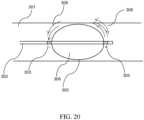
- a balloon ablation device for use with the electroporation systemis schematically illustrated in FIG. 20 . While the device is shown to be situated in a blood vessel 301, it can also be used in other anatomical areas such as a cardiac ventricle.
- the device shaft 302has an inflatable balloon 306 disposed in its distal portion. On either side of the balloon and mounted on the shaft are a proximal cathode electrode 303 and a distal anode electrode 304.
- the balloon surface 305is coated with a thin layer of a good insulator such as a biocompatible metal oxide (for example, aluminum oxide).
- the balloonWhen air is pumped in through the catheter shaft lumen and through appropriate openings (not shown) from the shaft into the balloon, the balloon can inflate, as the inflated shape in FIG. 20 depicts.
- the balloonIn ventricular applications such as cardiac ablation for VT, the balloon can serve to displace collateral structures away from the distal end of the catheter. Since the balloon surface is an insulator, when a DC voltage is applied between the electrodes, the current flow between electrodes and through the tissue is deflected around the balloon. The electric field is also correspondingly deflected around the surface of the balloon, and curves outward and can extend into the wall of the blood vessel, as shown by the schematic electric field lines 308 in the FIG..
- the distal electrode 304can be mounted on the outside of the shaft with external surface exposed, for intravascular ablation applications such as for example peripheral vascular applications for treatment of atherosclerosis where it is desired to ablate the vessel wall region or clear deposits.
- the distal electrode 304can be mounted on the inner side of the catheter shaft, so that the metal electrode is internally exposed.
- the distal electrodecould be recessed from the distal tip, as schematically shown in FIG. 20 . Such a device could be used in focal ablation applications.
- FIG. 21AAn alternate preferred embodiment of a balloon ablation device for use with the electroporation system according to an embodiment is shown schematically in FIG. 21A .
- the device shaft 171has an inflatable balloon 177 disposed in its distal portion.
- the balloon surface 176is coated with a thin layer of a good insulator such as a biocompatible metal oxide (for example, aluminum oxide).
- a biocompatible metal oxidefor example, aluminum oxide
- the region of the shaft within the ballooncan have at least one ultrasonic transducer 175 mounted thereon.
- the wall 178 of the balloonhas a varying cross section and is filled with a gas such as air.
- a gassuch as air.
- This interfacecan act as a mirror or reflecting surface for ultrasound.
- ultrasound rays 179 emitted by the transducer 175are reflected at the wall of the balloon and are subsequently focused on a ring-like region, shown with its annular regions 181 in a plane 180 and viewed edge-on in the illustration.
- the annular region external to the balloon where the ultrasound is focusedis shown in FIG.
- the ballooncan serve to displace collateral structures away from the distal end of the catheter. Since the balloon surface is an insulator, when a DC voltage is applied between the electrodes, the current flow between electrodes and through the tissue is deflected around the balloon. The electric field is also correspondingly deflected around the surface of the balloon, and curves outward and can extend into the wall of the blood vessel, as shown by the schematic electric field lines 191 in the FIG.. With the lowered irreversible electroporation threshold in the annular region of focused ultrasound in the vessel wall, the electric field in the annular region is sufficient to selectively drive irreversible electroporation.
- the distal electrode 174can be mounted on the outside of the shaft with external surface exposed, for intravascular ablation applications such as for example peripheral vascular applications for treatment of atherosclerosis where it is desired to ablate the vessel wall region or clear deposits.
- the distal electrode 174can be mounted on the inner side of the catheter shaft, so that the metal electrode is internally exposed.
- the distal electrodecould be recessed from the distal tip, as schematically shown in FIG. 21A . Such a device could be used in focal ablation applications.
- balloon ablation deviceWhile the specific embodiment of the balloon ablation device described above utilizes high-intensity focused ultrasound to selectively generate temperature increases in a given region in order to decrease the electroporation threshold, it must be noted that alternate energy delivery mechanisms such as microwaves could be utilized for the purpose of increasing tissue temperature by energy deposition in order to decrease the irreversible electroporation threshold electric field.
- the balloon ablation devices described in the foregoingcould also be used in pulmonary outflow tract applications to treat pulmonary hypertension, or in eosophageal or gastrointestinal applications where tissue ablation is an appropriate therapy.
- FIG. 22An ablation device for irreversible electroporation in the form of an expanding basket catheter is schematically illustrated in FIG. 22 .
- a sliding member 505Mounted on the shaft 501 of the device is a sliding member 505 which is attached to a system of struts 507. While the system of struts is initially substantially aligned with the length of the shaft in a folded configuration (not shown), it can unfold or open out like an umbrella by movement of the sliding member 505 along the shaft, resulting in the basket-like unfolded structure shown in FIG. 23.
- the system of strutsis only partially shown in the FIG..
- the basket construction or set of expanding strutscan comprise a superelastic alloy such as for instance an alloy of Nickel and Titanium often called Nitinol ® ; such a construction can be of use in a large vessel where a significant amount of expansion could be called for.
- a superelastic alloysuch as for instance an alloy of Nickel and Titanium often called Nitinol ® ; such a construction can be of use in a large vessel where a significant amount of expansion could be called for.
- On either side of the basket-like structure and disposed along the shaftare two electrodes 502 and 503. Bead-like electrodes 508 are present at corners of the strut assembly.
- the devicebe guided to a desired location inside a large vascular or other anatomical vessel (for example, the pulmonary outflow tract), positioned suitably and then unfolded. Subsequently, irreversible electroporation ablation can be applied with the electrodes on the basket device.
- the basket catheter with struts foldedcan have a lumen for passage of a suitable guidewire which could be used as a delivery system for appropriate placement of the basket catheter.
- a suitable guidewirewhich could be used as a delivery system for appropriate placement of the basket catheter.
- electrodes 502 or 503are selected as cathode, while the beads 508 are selected as anodes.
- a region of vessel wall that is located just proximal to or just distal to the beadscan be selectively ablated, depending on whether electrode 502 or electrode 503 respectively is activated as cathode.
- the rounded shape of the beads and their location on the outer edge of the basket (and thus close to the vessel wall)results in good ablation characteristics at the vessel wall.
- the voltage appliedcan be suitably selected so that an appropriate electric field is generated in the ablative region near the bead electrodes.
- the basket cathetercan further incorporate energy sources such as focused ultrasound or microwaves in order to selectively raise temperatures in localized regions and thereby lower the irreversible electroporation threshold.
- a methodincludes identifying, via a selection module of an electrode controller, a set of anode / cathode pairs from a set of electrodes of a multi-electrode catheter.
- the methodcan be performed using any suitable controller, such as for example, the controller 900 described above.
- the multi-electrode catheteris configured to be disposed about a portion of a heart. At least one of the anode / cathode pair including at least one anode electrode and at least one cathode electrode. In other embodiments, however, the anode / cathode pair can include multiple anode electrodes or cathode electrodes.
- the identifyingcan be based on input received from an input / output module of the electrode controller (e.g., manual input). In other embodiments, the identifying can be based on a predetermined schedule of electrodes. In yet other embodiments, the identifying can be performed automatically based on an impedance map as described herein.
- the methodfurther includes conveying a pacing signal to a pacing lead configured to be operatively coupled to the heart, and receiving, at a feedback module of the electrode controller, an electrocardiograph signal associated with a function of the heart.
- the methodfurther includes delivering, via a pulse delivery module of the electrode controller, a pulsed voltage waveform to the plurality of anode / cathode pairs according to a sequential pattern.
- a computer storage productwith a non-transitory computer-readable medium (also can be referred to as a non-transitory processor-readable medium) having instructions or computer code thereon for performing various computer-implemented operations.
- the computer-readable mediumor processor-readable medium
- the media and computer codemay be those designed and constructed for the specific purpose or purposes.
- non-transitory computer-readable mediainclude, but are not limited to: magnetic storage media such as hard disks, floppy disks, and magnetic tape; optical storage media such as Compact Disc/Digital Video Discs (CD/DVDs), Compact Disc-Read Only Memories (CD-ROMs), and holographic devices; magneto-optical storage media such as optical disks; carrier wave signal processing modules; and hardware devices that are specially configured to store and execute program code, such as Application-Specific Integrated Circuits (ASICs), Programmable Logic Devices (PLDs), Read-Only Memory (ROM) and Random-Access Memory (RAM) devices.
- ASICsApplication-Specific Integrated Circuits
- PLDsProgrammable Logic Devices
- ROMRead-Only Memory
- RAMRandom-Access Memory
- Examples of computer codeinclude, but are not limited to, micro-code or micro-instructions, machine instructions, such as produced by a compiler, code used to produce a web service, and files containing higher-level instructions that are executed by a computer using an interpreter.
- embodimentsmay be implemented using imperative programming languages (e.g., C, Fortran, etc.), functional programming languages (Haskell, Erlang, etc.), logical programming languages (e.g., Prolog), object-oriented programming languages (e.g., Java, C++, etc.) or other suitable programming languages and/or development tools.
- Additional examples of computer codeinclude, but are not limited to, control signals, encrypted code, and compressed code.
- controller 900is shown as optionally including the pacing module 902, in other embodiments, the controller 900 can interface with a separate pacing module.
- methods and/or events described aboveindicate certain events and/or procedures occurring in certain order, the ordering of certain events and/or procedures may be modified.
Landscapes
- Health & Medical Sciences (AREA)
- Life Sciences & Earth Sciences (AREA)
- Engineering & Computer Science (AREA)
- Nuclear Medicine, Radiotherapy & Molecular Imaging (AREA)
- Veterinary Medicine (AREA)
- Public Health (AREA)
- Biomedical Technology (AREA)
- General Health & Medical Sciences (AREA)
- Animal Behavior & Ethology (AREA)
- Surgery (AREA)
- Radiology & Medical Imaging (AREA)
- Biophysics (AREA)
- Molecular Biology (AREA)
- Medical Informatics (AREA)
- Heart & Thoracic Surgery (AREA)
- Physics & Mathematics (AREA)
- Pathology (AREA)
- Cardiology (AREA)
- Plasma & Fusion (AREA)
- Otolaryngology (AREA)
- Surgical Instruments (AREA)
- Measurement And Recording Of Electrical Phenomena And Electrical Characteristics Of The Living Body (AREA)
- Electrotherapy Devices (AREA)
Description
- The embodiments described herein relate generally to medical devices for therapeutic electrical energy delivery, and more particularly to systems for delivering electrical energy in the context of ablating tissue rapidly and selectively by the application of suitably timed pulsed voltages that generate irreversible electroporation of cell membranes.
- The past two decades have seen advances in the technique of electroporation as it has progressed from the laboratory to clinical applications. Known methods include applying brief, high voltage DC pulses to tissue, thereby generating locally high electric fields, typically in the range of hundreds of Volts/centimeter. The electric fields disrupt cell membranes by generating pores in the cell membrane, which subsequently destroys the cell membrane and the cell. While the precise mechanism of this electrically-driven pore generation ( or electroporation) awaits a detailed understanding, it is thought that the application of relatively large electric fields generates instabilities in the phospholipid bilayers in cell membranes, as well as mitochondria, causing the occurrence of a distribution of local gaps or pores in the membrane. If the applied electric field at the membrane exceeds a threshold value, typically dependent on cell size, the electroporation is irreversible and the pores remain open, permitting exchange of material across the membrane and leading to apoptosis or cell death. Subsequently, the surrounding tissue heals in a natural process.
- While pulsed DC voltages are known to drive electroporation under the right circumstances, the examples of electroporation applications in medicine and delivery methods described in the prior art do not discuss specificity of how electrodes are selected to accomplish the desired ablation.
- There is a need for selective energy delivery for electroporation and its modulation in various tissue types, as well as pulses that permit rapid action and completion of therapy delivery. There is also a need for more effective generation of voltage pulses and control methods, as well as appropriate devices or tools addressing a variety of specific clinical applications. Such more selective and effective electroporation delivery methods can broaden the areas of clinical application of electroporation including therapeutic treatment of a variety of cardiac arrhythmias.
WO97/25917 US2013/030430 discloses a medical system, including a medical device having a plurality of deployable arms, and at least one electrode on at least one of the plurality of arms. An electric signal generator is in communication with the medical device. The electric signal generator is programmed to deliver pulsed energy to the medical device sufficient to induce irreversible electroporation ablation.WO2012/051433 discloses a system for electrically ablating tissue of a patient through a plurality of electrodes includes a memory, a processor and a treatment control module stored in the memory and executable by the processor. The treatment control module generates an estimated treatment region based on the number of electrical pulses to be applied. - Catheter systems are disclosed for the selective and rapid application of DC voltage to drive electroporation. In accordance with one aspect of the invention, there is provided an apparatus as defined by
claim 1. Optional features are defined by the dependent claims. FIG. 1 is a perspective view of a portion of a catheter with multiple electrodes disposed along its shaft and wrapped around the pulmonary veins of the heart such that the portion of the catheter is placed in the epicardial space of the heart.FIG. 2A is a schematic illustration of an irreversible electroporation system that includes a DC voltage/signal generator, a controller capable of being configured to apply voltages to selected subsets of electrodes with independent subset selections for anode and cathode.FIG. 2B is a schematic illustration of an irreversible electroporation system that includes a DC voltage/signal generator and a controller according to an embodiment.FIG. 3 is an illustration of an ECG waveform showing the refractory periods during atrial and ventricular pacing, and the time windows for irreversible electroporation ablation.FIG. 4 is a schematic illustration of a user interface according to an embodiment showing various configurations for subsets of electrodes on the catheter to be identified as anodes or cathodes, and the ablation vectors therebetween.FIG. 5 is a schematic illustration of a user interface according to an embodiment, indicating the electrodes that are active and wrapped around the pulmonary veins of a patient anatomy, and that can be actively available for selection in bipolar ablation.FIG. 6 is a schematic illustration of a user interface according to an embodiment that illustrates a method of ablating along a cardiac isthmus line using two catheters, one of which is wrapped around the pulmonary veins.FIG. 7 is a schematic illustration of a user interface according to an embodiment that illustrates a method of focal ablation, wherein nearby electrodes on the same catheter are used for bipolar ablation with irreversible electroporation to ablate a region of contacting tissue at the distal catheter end, and showing a depth selection button that can be used to selectively adjust an ablation parameter.FIG. 8 is a schematic illustration according to an embodiment, showing a graphic window for selection of type of pacing to be used for electroporation therapy delivery.FIG. 9 is a schematic illustration of a user interface according to an embodiment, showing a graphic window with parameters associated with a selected pacing type.FIG. 10 is a schematic illustration of a user interface that illustrates a method of selecting anode electrode subsets and cathode electrode subsets on two different catheters according to an embodiment.FIG. 11 is a schematic illustration of a user interface that illustrates a method of selecting a single anode electrode and a single selected cathode electrode on the same catheter according to an embodiment.FIG. 12 is a schematic illustration of a waveform generated by the irreversible electroporation system and methods according to an embodiment, showing a balanced square wave.FIG. 13 is a schematic illustration of a waveform generated by the irreversible electroporation system and methods according to an embodiment, showing a balanced biphasic square wave.FIG. 14 is a schematic illustration of a waveform generated by the irreversible electroporation system and methods according to an embodiment, showing a progressive balanced biphasic square wave.FIG. 15 is a schematic illustration of a signal generator according to an embodiment, showing a capacitor bank connected to a set of switches.FIG. 16 is a schematic illustration of a voltage pulse-time plot produced by a high voltage DC signal generator according to an embodiment.FIG. 17 is a schematic depiction of a sequence of three biphasic pulses delivered by a voltage generator and using methods according to an embodiment, showing a pre-polarizing negative voltage pulse followed by a positive polarizing pulse.FIG. 18A is a schematic illustration of a distal portion of a catheter having two electrodes functioning as a cathode and an anode according to an embodiment.FIG. 18B is a schematic illustration of a distal portion of a catheter according to an embodiment having a recessed distal anode electrode, the illustration showing the current flow between electrodes.FIG. 18C is a schematic illustration of a distal portion of a catheter according to an embodiment, where electric field lines near the distal end of the catheter are schematically shown together with a region of focal ablation in tissue.FIG. 18D is a schematic illustration of a distal portion of a catheter according to an embodiment, where the catheter lumen has flowing fluid, possibly with ultrasonic waves conducted through the fluid, and the distal anode electrode has channels for fluid flow to exit the distal end of the catheter.FIG. 19A is an illustration of the simulation geometry showing a geometric model of the distal portion of a catheter and surrounding tissue types.FIG. 19B is an illustration of the distal portion of a catheter with a proximal electrode disposed externally on the shaft of the catheter and a distal electrode that is recessed and disposed on the inner side of the shaft of the catheter.FIG. 19C is an illustration of a longitudinal cross-section of the simulation geometry showing distal catheter geometry and tissue geometry together with electric field intensity contours for the case when the proximal electrode is disposed externally on the shaft of the catheter and the distal electrode is recessed and disposed on the inner side of the shaft of the catheter, according to an embodiment.FIG. 19D is an illustration of a longitudinal cross-section of the simulation geometry showing distal catheter geometry and tissue geometry together with electric field intensity contours for the case when the proximal and distal electrodes are both disposed externally on the shaft of the catheter, according to an embodiment.FIG. 20 is a schematic illustration of a balloon catheter according to an embodiment, where a balloon structure with an insulating exterior is located between anode and cathode electrodes for electroporation voltage delivery.FIG. 21A is a schematic illustration of a balloon catheter according to an embodiment, where a balloon structure with an insulating exterior and with at least one ultrasonic transducer is located between anode and cathode electrodes for electroporation voltage delivery.FIG. 21B is a schematic illustration of a balloon catheter according to an embodiment, where an annular ablation region abutting a vessel is shown.FIG. 22 is a schematic illustration of a basket ablation catheter for electroporation energy delivery according to an embodiment.- Systems and methods, the methods, however, not being part of the claimed invention, are disclosed for the selective and rapid application of DC voltage to drive electroporation. In some embodiments, the irreversible electroporation system described herein includes a DC voltage/signal generator and a controller capable of being configured to apply voltages to a selected multiplicity or a subset of electrodes, with anode and cathode subsets being selected independently. The controller is additionally capable of applying control inputs whereby selected pairs of anode-cathode subsets of electrodes can be sequentially updated based on a pre-determined sequence.
- In some embodiments, an irreversible electroporation system includes a DC voltage/signal generator and a controller capable of being configured to apply voltages to a selected multiplicity or a subset of electrodes, with independent subset selections for anode and cathode. Further, the controller is capable of applying control inputs whereby selected pairs of anode-cathode subsets of electrodes can be sequentially updated based on a pre-determined sequence. The generator can output waveforms that can be selected to generate a sequence of voltage pulses in either monophasic or biphasic forms and with either constant or progressively changing amplitudes. In one embodiment, a DC voltage pulse generation mechanism is disclosed that can use amplified voltage spikes generated by the action of a switch connected to a capacitor bank, resulting in a biphasic, asymmetric micro pulse waveform for cardiac ablation where the first phase provides a brief pre-polarizing pulse that is followed by a finishing pulse in the second phase. Such pre-polarization can result in more effective pulsed voltage electroporation delivery. Methods of control and DC voltage application from a generator capable of selective excitation of sets of electrodes are disclosed. Devices are disclosed for more effective DC voltage application through ionic fluid irrigation and ultrasonic agitation, possibly including insulating balloon constructions to displace electrodes from collateral structures, and for use in intravascular applications. Such devices for generating irreversible electroporation can be utilized in cardiac therapy applications such as ablation to treat Ventricular Tachycardia (VT) as well as in intravascular applications. In some embodiments, the use of temperature to selectively ablate tissue is described, as the threshold of irreversible electroporation is temperature-dependent, utilizing focused kinetic energy to select the predominant tissue type or region it is desired to ablate
- In some embodiments, an apparatus includes a voltage pulse generator and an electrode controller. The voltage pulse generator is configured to produce a pulsed voltage waveform. The electrode controller is configured to be operably coupled to the voltage pulse generator and a medical device including a series of electrodes. The electrode controller is implemented in at least one of a memory or a processor, and includes a selection module and a pulse delivery module. The selection module is configured to select a subset of electrodes from the series of electrodes. The selection module is configured identify at least one electrode as an anode and at least one electrode as a cathode. The pulse delivery module is configured to deliver an output signal associated with the pulsed voltage waveform to the subset of electrodes.
- In some embodiments, an apparatus includes a voltage pulse generator and an electrode controller. The voltage pulse generator is configured to produce a pulsed voltage waveform. The electrode controller is configured to be operably coupled to the voltage pulse generator and a medical device including a series of electrodes. The electrode controller is implemented in at least one of a memory or a processor, and includes a selection module and a pulse delivery module. The selection module is configured to select a set of anode / cathode pairs, each anode / cathode pair including at least one anode electrode and at least one cathode electrode. In some embodiments, for example, the anode / cathode pair can include one anode and multiple cathodes (or vice-versa). The pulse delivery module is configured to deliver an output signal associated with the pulsed voltage waveform to the plurality of anode / cathode pairs according to a sequential pattern.
- In some embodiments, a non-transitory processor readable medium storing code representing instructions to be executed by a processor includes code to cause the processor to identify a set of anode / cathode pairs from a set of electrodes of a multi-electrode catheter. The multi-electrode catheter is configured to be disposed about a portion of a heart, and at least one anode / cathode pair includes at least one anode electrode and at least one cathode electrode. The code further includes code to convey a pacing signal to a pacing lead configured to be operatively coupled to the heart. The code further includes code to receive an electrocardiograph signal associated with a function of the heart. The code further includes code to deliver a pulsed voltage waveform to the set of anode / cathode pairs according to a sequential pattern.
- In some embodiments, a method, not part of the claimed invention, includes identifying, via a selection module of an electrode controller, a set of anode / cathode pairs from a set of electrodes of a multi-electrode catheter. The multi-electrode catheter is configured to be disposed about a portion of a heart. At least one anode / cathode pair includes at least one anode electrode and at least one cathode electrode. A pacing signal is conveyed to a pacing lead configured to be operatively coupled to the heart. The method further includes receiving, at a feedback module of the electrode controller, an electrocardiograph signal associated with a function of the heart. The method further includes delivering, via a pulse delivery module of the electrode controller, a pulsed voltage waveform to the set of anode / cathode pairs according to a sequential pattern.
- In some embodiments, an apparatus includes a signal generator for the generation of DC voltage pulses. The signal generator is configured to produce a biphasic waveform having a pre-polarizing pulse followed by a polarizing pulse. The pre-polarizing pulse is generated by utilizing voltage spikes generated from switching on a discharge of a capacitor bank.
- In some embodiments, an apparatus includes a catheter shaft, a cathode electrode and an anode electrode. The catheter shaft has an outer side and an inner side. The cathode electrode is coupled to a distal end portion of the catheter shaft such that a cathode surface is exposed on the outer side of the catheter shaft. The anode electrode is coupled to the distal end portion distal relative to the cathode electrode. The anode electrode is recessed within the catheter shaft and coupled to the catheter shaft such that an anode surface is exposed on the inner side of the catheter shaft.
- In some embodiments, an apparatus includes a catheter shaft, an inflatable balloon, a first electrode and a second electrode. The catheter shaft has a distal end portion. The inflatable balloon is coupled to the distal end portion. An outer surface of the balloon is an electrical insulator. The first electrode is coupled to a proximal side of the balloon, and the second electrode is coupled to a distal side of the balloon.
- In some embodiments, an apparatus includes a catheter shaft having a distal end portion, an expandable basket structure, a first electrode, a second electrode, and a set of spherical electrodes. The expandable basket structure is coupled to the distal end portion of the catheter shaft. The first electrode coupled to a proximal side of the expandable basket structure. The second electrode is coupled to a distal side of the expandable basket structure. The set of spherical electrodes is coupled to a corresponding set of rounded corners of the expandable basket structure.
- As used in this specification, the singular forms "a," "an" and "the" include plural referents unless the context clearly dictates otherwise. Thus, for example, the term "a member" is intended to mean a single member or a combination of members, "a material" is intended to mean one or more materials, "a processor" is intended to mean a single processor or multiple processors; and "memory" is intended to mean one or more memories, or a combination thereof.
- As used herein, the terms "about" and "approximately" generally mean plus or minus 10% of the value stated. For example, about 0.5 would include 0.45 and 0.55, about 10 would include 9 to 11, about 1000 would include 900 to 1100.
- As shown in
FIG. 1 , in some embodiments a Pulmonary Vein isolation (PV isolation)ablation catheter device 15 with a multiplicity of electrodes (indicated by dark bands such as those marked as 17) disposed along its mid-section is wrapped in the epicardial space around thepulmonary veins heart 7 in a subject or patient anatomy, with theends ablation catheter 15 and any of the catheters described herein can be similar to the ablation catheters described inPCT Publication No. WO2014/025394, entitled "Catheters, Catheter Systems, and Methods for Puncturing Through a Tissue Structure," filed on March 14, 2013 ("the `394 PCT Application). Theablation catheter 15 can be disposed about thepulmonary veins ablation catheter 15 can be disposed about thepulmonary veins heart 7 using a puncturing apparatus disposed via a subxiphoid pericardial access location and a guidewire-based delivery method as described in the '394 PCT Application. After theends - A DC voltage for electroporation can be applied to subsets of electrodes identified as anode and cathode, respectively, on approximately opposite sides of the closed contour defined by the shape of the
catheter 15 around the pulmonary veins. The DC voltage is applied in brief pulses sufficient to cause irreversible electroporation. In any of the systems and methods, not part of the claimed invention, described herein, the pulse or waveform can be in the range of 0.5 kV to 10 kV and more preferably in therange 1 kV to 2.5 kV, so that a threshold electric field value of around 200 Volts/cm is effectively achieved in the cardiac tissue to be ablated. In some embodiments, the marked electrodes can be automatically identified, or manually identified by suitable marking, on an X-ray or fluoroscopic image obtained at an appropriate angulation that permits identification of the geometric distance between anode and cathode electrodes, or their respective centroids. In one embodiment, the DC voltage generator setting for irreversible electroporation is then automatically identified by the electroporation system based on this distance measure. In an alternate embodiment, the DC voltage value is selected directly by a user from a suitable dial, slider, touch screen, or any other user interface. The DC voltage pulse results in a current flowing between the anode and cathode electrodes on opposite sides of the contour defined by the catheter shape, with said current flowing through the cardiac wall tissue and through the intervening blood in the cardiac chamber, with the current entering the cardiac tissue from the anode and returning back through the cathode electrodes. The forward and return current paths (leads) are both inside the catheter. Areas of cardiac wall tissue where the electric field is sufficiently large for irreversible electroporation are ablated during the DC voltage pulse application. The number of electrodes on the PV isolation ablation catheter can be in the range between 8 and 50, and more preferably in the range between 15 and 40. - A schematic diagram of the electroporation system according to an embodiment is shown in
FIG. 2A . The system includes a DC voltage/signal generator 23 that is driven by acontroller unit 21 that interfaces with acomputer device 24 by means of a two-way communication link 29. The controller can perform channel selection and routing functions for applying DC voltages to appropriate electrodes that have been selected by a user or by thecomputer 24, and apply the voltages via a multiplicity of leads (shown collectively as 26) to acatheter device 22. The catheter device can be any of the catheters shown and described herein or in the '394 PCT Application. Some leads from thecontroller 21 could also carry pacing signals to drive pacing of the heart through a separate pacing device (not shown). The catheter device can also send back information such as ECG (electrocardiograph) recordings or data from other sensors back to thecontroller 21 as indicated by thedata stream 25, possibly on separate leads. While theDC voltage generator 23 sends a DC voltage to thecontroller 21 throughleads 27, the voltage generator is driven by control and timinginputs 28 from thecontroller unit 21. - In some embodiments, the electrode controller can include one or more modules and can automatically perform channel selection (e.g., identification of a subset of electrodes to which the voltage pulses will be applied), identification of the desired anode / cathode pairs, or the like. For example,
FIG. 2B shows an electroporation system according to an embodiment that includes anelectrode controller 900 and asignal generator 925. Theelectrode controller 900 is coupled to acomputer 920 or other input / output device, and is configured to be operable coupled to amedical device 930. Themedical device 930 can be one or more multi-electrode catheters, of the types shown and described herein. Further themedical device 930 can be coupled to, disposed about and/or in contact with a target tissue, such as the heart H. In this manner, as described herein, the electroporation system, including theelectrode controller 900 and thesignal generator 925, can deliver voltage pulses to the target tissue for therapeutic purposes. - The
controller 900 can include amemory 911, aprocessor 910, and an input / output module (or interface) 901. Thecontroller 900 can also include apacing module 902, afeedback module 905, apulse delivery module 908, and aselection module 912. Theelectrode controller 900 is coupled to acomputer 920 or other input / output device via the input / output module (or interface) 901. - The
processor 910 can be any processor configured to, for example, write data into and read data from thememory 911, and execute the instructions and/or methods stored within thememory 911. Furthermore, theprocessor 910 can be configured to control operation of the other modules within the controller (e.g., thepacing module 902, thefeedback module 905, thepulse delivery module 908, and the selection module 912). Specifically, the processor can receive a signal including user input, impedance, heart function or the like information and determine a set of electrodes to which voltage pulses should be applied, the desired timing and sequence of the voltage pulses and the like. In other embodiments, theprocessor 910 can be, for example, an application-specific integrated circuit (ASIC) or a combination of ASICs, which are designed to perform one or more specific functions. In yet other embodiments, the microprocessor can be an analog or digital circuit, or a combination of multiple circuits. - The
memory device 910 can be any suitable device such as, for example, a read only memory (ROM) component, a random access memory (RAM) component, electronically programmable read only memory (EPROM), erasable electronically programmable read only memory (EEPROM), registers, cache memory, and/or flash memory. Any of the modules (thepacing module 902, thefeedback module 905, thepulse delivery module 908, and the selection module 912) can be implemented by theprocessor 910 and/or stored within thememory 910. - As shown, the
electrode controller 900 operably coupled to thesignal generator 925. The signal generator includes circuitry, components and/or code to produce a series of DC voltage pulses for delivery to electrodes included within themedical device 930. For example, in some embodiments, thesignal generator 925 can be configured to produce a biphasic waveform having a pre-polarizing pulse followed by a polarizing pulse. Thesignal generator 925 can be any suitable signal generator of the types shown and described herein. - The
pulse delivery module 908 of theelectrode controller 900 includes circuitry, components and/or code to deliver an output signal associated with the pulsed voltage waveform produced by thesignal generator 925. This signal (shown as signal 909) can be any signal of the types shown and described herein, and can be of a type and/or have characteristics to be therapeutically effective. In some embodiments, thepulse delivery module 908 receives input from theselection module 912, and can therefore send thesignal 909 to the appropriate subset of electrodes, as described herein. - The
selection module 912 includes circuitry, components and/or code to select a subset of electrodes from the electrodes included within themedical device 930, as described herein. In some embodiments, theselection module 912 is configured identify at least one electrode from the subset of electrodes as an anode and at least one electrode from the subset of electrodes as a cathode. In some embodiments, theselection module 912 is configured to select a subset of electrodes from more than onemedical device 930, as described herein. - In some embodiments, the
selection module 912 can select the subset of electrodes based on input received from the user via the input /output module 901. For example, in some embodiments, the user can use visualization techniques or other methods to identify the desired electrodes, and can manually enter those electrodes, as described herein. - In other embodiments, the
selection module 912 is configured to select the subset of electrodes based on a predetermined schedule of the set of electrodes. For example, in some embodiments, theelectrode controller 900 can be configured accommodate differentmedical devices 930 having different numbers and/or types of electrodes. In such embodiments, theselection module 912 can retrieve a predetermined schedule of electrodes to which a series of voltage pulses can be applied, based on the specific type ofmedical device 930. - In yet other embodiments, the
selection module 912 is configured to select the subset of electrodes automatically based on at least one of an impedance associated with the subset of electrodes, a distance between the first electrode and the second electrode, and a characteristic associated with a target tissue. For example, in some embodiments, theelectrode controller 900 includes thefeedback module 905 that can receive feedback from the medical device 930 (as identified by the signal 906). Thefeedback module 905 includes circuitry, components and/or code to determine an impedance between various electrodes (as described herein). Thus, in such embodiments,_the selection module 912 can select the subset of electrodes automatically based the impedance. - In some embodiments, the
electrode controller 900 optionally includes thepacing module 902. Thepacing module 902 includes circuitry, components and/or code to produce a pacing signal (identified as signal 903) that can be delivered to the target tissue (or heart) via a pacing lead. As described herein, thepacing module 902 can facilitate any suitable "mode" of operation desired, such as a standard pacing, an overdrive pacing option (for pacing at a faster-than-normal heart rate), an external trigger option (for pacing from an externally generated trigger), and a diagnostic pacing option. - As shown in
FIG. 3 , given atrial or ventricular pacing inputs to the heart (e.g., from thepacing module 902 of the electrode controller 900), the resultingECG waveform 32 has appropriate respectiverefractory time intervals - In some embodiments, the ablation controller and signal generator can be mounted on a rolling trolley, and the user can control the device using a touchscreen interface that is in the sterile field. Referring to
FIG. 2B , in such embodiments, thecomputer 920 can be a touchscreen device. The touchscreen can be for example an LCD touchscreen in a plastic housing mountable to a standard medical rail or post and can be used to select the electrodes for ablation and to ready the device to fire. The interface can for example be covered with a clear sterile plastic drape. The operator can select the number of electrodes involved in an automated sequence. The touch screen graphically shows the catheters that are attached to the controller. In one embodiment the operator can select electrodes from the touchscreen with appropriate graphical buttons. The operator can also select the pacing stimulus protocol (either internally generated or externally triggered) from the interface. Once pacing is enabled, and the ablation sequence is selected, the operator can initiate or verify pacing. Once the operator verifies that the heart is being paced, the ablation sequence can be initiated by holding down a hand-held trigger button that is in the sterile field. The hand-held trigger button can be illuminated red to indicate that the device is "armed" and ready to ablate. The trigger button can be compatible for use in a sterile field and when attached to the controller can be illuminated a different color, for example white. When the device is firing, the trigger button flashes in sequence with the pulse delivery in a specific color such as red. The waveform of each delivered pulse is displayed on the touchscreen interface. A graphic representation of the pre and post impedance between electrodes involved in the sequence can also be shown on the interface, and this data can be exported for file storage. - In some embodiments, an impedance map can be generated based on voltage and current recordings across anode-cathode pairs or sets of electrodes, and an appropriate set of electrodes that are best suited for ablation delivery in a given region can be selected based on the impedance map or measurements, either manually by a user or automatically by the system. Such an impedance map can be produced, for example, by the
feedback module 905, or any other suitable portion of theelectrode controller 900. For example, if the impedance across an anode/cathode combination of electrodes is a relatively low value (for example, less than 25 Ohms), at a given voltage the said combination would result in relatively large currents in the tissue and power dissipation in tissue. In such circumstances, this electrode combination would then be ruled out (e.g., via the selection module 912) for ablation due to safety considerations, and alternate electrode combinations would be sought by the user. In a preferred embodiment, a pre-determined range of impedance values, for example 30 Ohms to 300 Ohms, could be used as an allowed impedance range within which it is deemed safe to ablate. Thus, in some embodiments, an electrode controller can automatically determine a subset of electrodes to which voltage pulses should be applied. - The waveforms for the various electrodes can be displayed and recorded on the case monitor and simultaneously outputted to a standard connection for any electrophysiology (EP) data acquisition system. With the high voltages involved with the device, the outputs to the EP data acquisition system needs to be protected from voltage and/or current surges. The waveforms acquired internally can be used to autonomously calculate impedances between each electrode pair. The waveform amplitude, period, duty cycle, and delay can all be modified, for example via a suitable Ethernet connection. Pacing for the heart is controlled by the device and outputted to the pacing leads and a protected pacing circuit output for monitoring by a lab.
- While a touchscreen interface is one preferred embodiment, other user interfaces can be used to control the system such as a graphical display on a laptop or monitor display controlled by a standard computer mouse or joystick.
FIG. 4 shows a schematic rendering of a portion of the user interface of the electroporation system. The four windows A, B, C and D shown in the FIG. represent four different choices of electrode subsets for anode and cathode selection. The PV isolation ablation catheter is represented by a string of numbered electrodes as indicated by 41, wrapped around thearea 42 of the pulmonary veins represented by the enclosed region in this schematic diagram. Referring to B in the FIG., the dashed-line vectors 46 represent approximate current vectors, with their tips at the cathodes and tails or bases at the anodes; in this FIG., the three electrodes marked 43 are cathodes, and the single electrode marked 44 is the anode. The windows A, C and D in this FIG. show other choices of cathode and anode electrode subsets, in each case with accompanying approximate current density vectors shown by dashed arrows. It is clear from the FIG. that the user can select various subsets of electrodes as cathode or anode, depending on the region to be ablated along the length of the PV isolation catheter. In one embodiment, the user can make one selection of cathode and anode subsets, and the system can take this selection as input to generate an ablation sequence that moves around the ring or contour defined by the shape of the PV isolation catheter, for example moving clockwise at each step with a one-electrode displacement. In this manner, the pair of cathode and anode electrode subsets can be sequentially updated for ablation purposes, so that if there areN electrodes, afterN updates the entire contour has been updated such that the tips of the current arrows shown as 46 have swept once around the contour completely. - In some cases, the portion of the PV isolation catheter with electrodes may be longer than needed to wrap around a given patient's pulmonary veins; in this event, a smaller number of electrodes suffices to wrap around the contour of the pulmonary veins. These define the number of "active" electrodes to be used in the ablation process. In the specific example shown in
FIG. 5 for a 30-electrode PV isolation catheter, the set of electrodes wrapped around the pulmonary veins, represented by 51, are the electrodes that would be used in the ablation process, and are called out by thelabel 50 as the set of active electrodes, while the remaining five electrodes represented by 52 are not used in the ablation process as they are not located in suitable positions. - In one embodiment of the electroporation system disclosed herein, multiple catheters could be used for ablation, with anode and cathode subsets respectively chosen to lie on different catheters. In one exemplary use, not part of the claimed invention as such, of such multi-device electroporation, two catheters are connected to the controller unit of the electroporation system. In some instances of ablation procedures for the treatment of Atrial Fibrillation (AF), in addition to isolating the pulmonary veins, it is also useful to generate an ablation line that separates or isolates regions around the mitral valve. Such a line is often termed a "Mitral Isthmus Line," and is a line running from an Inferior aspect of the PV isolation contour to the outer edge of the mitral valve in the left atrium. In some embodiments, a method of use, also not part of the claimed invention as such, of the systems described herein includes inserting a coronary sinus catheter with multiple electrodes into the coronary sinus. As shown in
FIG. 6 , electrodes marked as 66 on thecoronary sinus catheter 63, and electrodes marked as 65 on thePV isolation catheter 62, are further selected as active subsets of electrodes for ablation, as indicated in theindication window 61 for the anode and cathode subsets. Thus in effect the electrodes of thecoronary sinus catheter 63 are utilized to define the mitral isthmus line, and irreversible electroporation ablation can be effectively performed on the left atrial wall to generate a mitral isthmus ablation line. - In a some embodiments, the system (any of the generators and controllers described herein) can deliver rectangular-wave pulses with a peak maximum voltage of about 5 kV into a load with an impedance in the range of 30 Ohm to 3000 Ohm for a maximum duration of 200 µs, with a 100 µs maximum duration being still more preferred. Pulses can be delivered in a multiplexed and synchronized manner to a multi-electrode catheter inside the body with a duty cycle of up to 50 % (for short bursts). The pulses can generally be delivered in bursts, such as for example a sequence of between 2 and 10 pulses interrupted by pauses of between 1 ms and 1000 ms. The multiplexer controller is capable of running an automated sequence to deliver the impulses/impulse trains (from the DC voltage signal/impulse generator) to the tissue target within the body. The controller system is capable of switching between subsets/nodes of electrodes located on the single use catheter or catheters (around or within the heart). Further, the controller can measure voltage and current and tabulate impedances in each electrode configuration (for display, planning, and internal diagnostic analysis). It can also generate two channels of cardiac pacing stimulus output, and is capable of synchronizing impulse delivery with the internally generated cardiac pacing and/or an external trigger signal. In one embodiment, it can provide sensing output/connection for access to bio potentials emanating from each electrode connected to the system (with connectivity characteristics being compatible with standard electrophysiological laboratory data acquisition equipment).
- In a some embodiments, the controller (e.g., the controller 900) can automatically "recognize" the single-use disposable catheter when it is connected to the controller output (prompting internal diagnostics and user interface configuration options). The controller can have at least two unique output connector ports to accommodate up to at least two catheters at once (for example, one 30- electrode socket and one 10-electrode socket; a 2-pole catheter would connect to the 10-pole socket). The controller device can function as long as at least one recognized catheter is attached to it. In a preferred embodiment, the controller can have several sequence configurations that provide the operator with at least some variety of programming options. In one configuration, the controller can switch electrode configurations of a bipolar set of electrodes (cathode and anode) sequentially in a clockwise manner (for example, starting at stepn, in the next step of the algorithm, cathoden+1 and anoden+1 are automatically selected, timed to the synchronizing trigger). With the 30-pole catheter the electrodes are arranged in a quasi-circumference around the target. Thus in the first sequence, pulse delivery occurs so that the vector of current density changes as the automated sequencing of the controller switches "on" and "off" between different electrodes surrounding the tissue target sequence. The current density vectors generally cross the target tissue but in some configurations the current density could be approximately tangential to the target. In a second sequence configuration, the impulses are delivered to user-selected electrode subsets of catheters that are connected to the device (the vector of current density does not change with each synchronized delivery). A third sequence configuration example is a default bipolar pulse sequence for the simplest 2-pole catheter. The user can also configure the controller to deliver up to 2 channels of pacing stimulus to electrodes connected to the device output. The user can control the application of DC voltage with a single handheld switch. A sterile catheter or catheters can be connected to the voltage output of the generator via a connector cable that can be delivered to the sterile field. In one embodiment, the user activates the device with a touch screen interface (that can be protected with a single-use sterile transparent disposable cover commonly available in the catheter lab setting). The generator can remain in a standby mode until the user is ready to apply pulses at which point the user/assistant can put the generator into a ready mode via the touchscreen interface. Subsequently the user can select the sequence, the active electrodes, and the cardiac pacing parameters.
- Once the catheter has been advanced to or around the cardiac target, the user can initiate electrically pacing the heart (using a pacing stimulus generated by the ablation controller or an external source synchronized to the ablation system). The operator verifies that the heart is being paced and uses the hand-held trigger button to apply the synchronized bursts of high voltage pulses. The system can continue delivering the burst pulse train with each cardiac cycle as long as the operator is holding down a suitable "fire" button or switch. During the application of the pulses, the generator output is synchronized with the heart rhythm so that short bursts are delivered at a pre-specified interval from the paced stimulus. When the train of pulses is complete, the pacing continues until the operator discontinues pacing.
FIG. 7 shows a portion of a graphical user interface according to an embodiment for focal ablation with a bipolar or 2-electrode catheter. In some embodiments, the graphical user interface can be a touchscreen interface. Agraphical icon 71 for a bipolar catheter is shown along with a depth selection button 72 for selecting a desired ablation depth. In one embodiment of the system, based on the latter depth setting, the system can select an appropriate voltage value to apply in order to ensure that an electric field sufficient to cause irreversible electroporation is applied up to the desired depth.- In some embodiments, a pacing selection interface on a portion of the user interface of the electroporation system is shown in
FIG. 8 . The pacing selection interface has various options such as anoverdrive pacing option 81 for pacing at a faster-than-normal heart rate, anexternal trigger option 82 for pacing from an externally generated trigger, and adiagnostic pacing option 83. By clicking the "Select" button for a given option, that option is selected. - As an example of a pacing option selected,
FIG. 9 shows a portion the user interface of the electroporation system with pacing from an external trigger selected for the pacing option. The selectedoption 86 is displayed along with the pacing characteristics andwaveform 87 for the user to visualize. FIG. 10 shows a portion the user interface of the electroporation system for selection of anode and cathode electrodes, with two catheters connected to the system. One of the catheters is aPV isolation catheter 91 while the other is amulti-electrode catheter 92. Thebuttons FIG. 11 .- The controller and generator can output waveforms that can be selected to generate a sequence of voltage pulses in either monophasic or biphasic forms and with either constant or progressively changing amplitudes.
FIG. 12 shows a rectangular wave pulse train where thepulses 101 have a uniform height or maximum voltage.FIG. 13 shows an example of a balanced biphasic rectangular pulse train, where each positive voltage pulse such as 103 is immediately followed by a negative voltage pulse such as 104 of equal amplitude and opposite sign. While in this example the biphasic pulses are balanced with equal amplitudes of the positive and negative voltages, in other embodiments an unbalanced biphasic waveform could also be used as may be convenient for a given application. - Yet another example of a waveform or pulse shape that can be generated by the system is illustrated in
FIG. 14 , which shows a progressive balanced rectangular pulse train, where each distinct biphasic pulse has equal-amplitude positive and negative voltages, but each pulse such as 107 is larger in amplitude than itsimmediate predecessor 106. Other variations such as a progressive unbalanced rectangular pulse train, or indeed a wide variety of other variations of pulse amplitude with respect to time can be conceived and implemented by those skilled in the art based on the teachings herein. - The time duration of each irreversible electroporation rectangular voltage pulse could lie in the range from 1 nanosecond to 10 milliseconds, with the
range 10 microseconds to 1 millisecond being more preferable and therange 50 microseconds to 300 microseconds being still more preferable. The time interval between successive pulses of a pulse train could be in the range of 10 microseconds to 1 millisecond, with therange 50 microseconds to 300 microseconds being more preferable. The number of pulses applied in a single pulse train (with delays between individual pulses lying in the ranges just mentioned) can range from 1 to 100, with therange 1 to 10 being more preferable. As described in the foregoing, a pulse train can be driven by a user-controlled switch or button, in one embodiment preferably mounted on a hand-held joystick-like device. In one mode of operation a pulse train can be generated for every push of such a control button, while in an alternate mode of operation pulse trains can be generated repeatedly during the refractory periods of a set of successive cardiac cycles, for as long as the user-controlled switch or button is engaged by the user. - In one embodiment of a biphasic waveform, a brief pre-polarization pulse can be applied just prior to the application of a polarizing rectangular pulse. The rapid change in electric field in tissue, in addition to the electric field magnitude, driven by this type of pulse application incorporating a pre-polarizing pulse can promote a more rapid and effective tissue ablation in some applications. A schematic diagram of a voltage/signal generator for the purpose of generating such a waveform employing intrinsic amplification of voltage spikes arising from switching is given in
FIG. 15 . A DC voltage is generated from the discharge of a suitable capacitor bank 111 (powered by a suitable charging circuit that is not shown and that would be familiar to those skilled in the art) with a suitable high-voltage diode orrectifier 112 serving to ensure voltage polarity. While in one embodiment of the signal generator the voltage discharge passes initially through a snubber or transient-suppression circuit 113 that strongly suppresses transients, in an alternate embodiment an alternate signal path is available via aswitch unit 116 that detects and lets through a brief initial voltage spike after a possible voltage inversion. The signal then passes through an Insulated Gate Bipolar Transistor (IGBT) high-power switch 115 and is accessible atterminals 117 for connection to catheter electrodes. When no pre-polarizing pulse is required, theswitch unit 116 would not be present, and the signal passes (after transient-suppression in the snubber circuit 113) initially through a Metal Oxide Semiconductor Field Effect Transistor (MOSFET)switch 114 before passing through theIGBT switch 115. The IGBT interfaces better with a wider range of load impedances (from tissue), while the faster switching speed of the MOSFET can drive a suitably fast turn-on/turn-off of the IGBT switch, so that using them in the sequence shown inFIG. 15 can be advantageous. - In order to generate a sequence of rectangular pulses, the time constant associated with the capacitor bank discharge is chosen to be significantly longer than an individual pulse duration. If the charging circuit of the capacitor bank is much more rapid, a sequence of very highly rectangular pulses can be generated from repeated capacitor bank discharges. As shown in
FIG. 16 , when a capacitor bank is suddenly discharged by closing a switch, the voltage can briefly be amplified and spike as indicated by 122 before settling to anormal discharge pattern 121. The inductance of leads connected to the capacitor forms a tank circuit with the capacitor, and in many cases this tank circuit is rapidly driven to resonance by the discharge, leading to the voltage amplification seen in the spikingbehavior 122. Indeed, by suitably controlling lead inductance and resistance, the extent of spike generated (spike amplitude and duration) can be further controlled. Such additional inductance/resistance or spike control circuitry can be included in theswitch unit 116 shown inFIG. 15 . Thus theswitch 116 plays a gatekeeping role akin to the notion of "Maxwell's demon" in statistical physics, allowing the passage of some types of intrinsically amplified voltage spikes, and accordingly the signal generator ofFIG. 15 can also be termed a Maxwell amplifier. - A schematic representation of a biphasic pulse with pre-polarization is shown in
FIG. 17 , where each rectangular polarizing pulse such as 125 is preceded by a pre-polarizingnegative voltage spike 126 derived from transient spiking from a generator of the type shown inFIG. 15 . The value of the negative spike voltage peak VL could be determined by the spike control circuitry of theswitch unit 116 as discussed above. The biphasic pulses involve a time duration T1 for the pre-polarizing spike, a duration T2 for the rectangular polarizing pulse, with a time delay Td indicated by 127 inFIG. 17 between successive biphasic pulses. Typical values of T2 could be of the order of 100 microseconds, while T1 could lie in therange 5 microseconds to 50 microseconds and the delay time Td could be in the range 100 microseconds to 300 microseconds. All of these parameters can be determined by the design of the signal generator, and in various embodiments could also be determined by user control as may be convenient for a given clinical application. The specific examples and descriptions herein are exemplary in nature and variations can be developed by those skilled in the art based on the material taught herein without departing from the scope of the embodiments described herein. - A catheter device for focal ablation with the electroporation system according to an embodiment is shown schematically in
FIG. 18A . Thefocal ablation catheter 131 has two electrodes disposed in the distal section of the catheter, with a relatively proximally placedcathode electrode 133 of length L1 exposed on the catheter shaft and a relatively distally placedanode electrode 134 of length L2 mounted on the inner section of the shaft. The catheter shaft is made of a material with high dielectric strength such as for example a polymer comprising Teflon. Thus thedistal electrode 134 is covered by the polymeric shaft and is not exposed to the blood pool on the shaft exterior. Both electrodes are metallic, and in one embodiment the anode could be poly-metallic in construction, for example comprising regions of Titanium and regions of Platinum. - As shown in
FIG. 18B , theanode 141 is recessed from the distal tip, and could be placed with its distal portion between 0.5 mm and 10 mm away from the distal end of the catheter. While the recessed and interior placement of the anode electrode is counterintuitive, it can be an effective means of enhancing electroporation efficacy and safety selectively for focal ablation. As indicated in the FIG., the schematically depicted (negative) current density flowing from the cathode to the anode indicated by the stream ofarrows 142 bends around thedistal edge 143 of the catheter shaft resulting in a region of high curvature of the current density, and correspondingly curved electric field lines as well. If the anode electrode is recessed, the highest curvature region at the edge of the electrode where the strongest electric field occurs is also displaced proximally, so that the electric field around the distal tip of the catheter itself is not so large as to cause any increased local heating, while remaining large enough to cause irreversible electroporation.FIG. 18C schematically showselectric field lines 152 as they curve to enter thedistal catheter end 151, resulting in a zone orregion 153 distal to the catheter with a relatively uniform electric field. The electric field in this region would not be as uniform with a standard, externally placed electrode on the catheter, and further would generally have regions of very high intensity. The recessed interior placement of the distal electrode therefore results in superior and safe electroporation ablation delivery for focal ablation in a selective zone distal to the catheter tip. While in one embodiment the anode electrode can be a hollow ring, in other embodiments it could have a different form such as a cylinder with multiple longitudinal holes or channels. - In some embodiments, the interior lumen of the catheter can carry a fluid delivered out through the distal end of the catheter. The fluid can be an ionic fluid such as isotonic or hypertonic saline and can enhance electrical conductivity in the distal region of the catheter and beyond the distal end ensuring a proper and more uniform distribution of local electric field in a distal region around the catheter. As shown in
FIG. 18D , theinner lumen 163 of the catheter carries a flowing fluid indicated by the arrows, while theanode 161 is in the shape of a cylinder that has longitudinal channels through which fluid can flow. The anode electrode is shown incross section 162 where the multiple through-channels are visible. The saline or ionic fluid delivered through the channels can act as an ion bridge through which good electrical current conduction is possible in the vicinity of the catheter's distal end, resulting in a more uniform distribution of local electric field and electroporation energy delivery. Further, the flow of saline fluid itself can dislodge tissue debris or any bubbles generated by the electroporation-driven breakdown of tissue in the region around the distal catheter tip. In one embodiment, ultrasonic waves schematically shown as 164 inFIG. 18D can be applied to the fluid to further ensure that any bubbles that may be lodged on the catheter surface in its distal region are dislodged, again for purposes of maintaining relative uniformity of the local electric field. The ultrasonic waves or ultrasound through the fluid can be generated by suitable piezoelectric transducers mounted more proximally along the shaft of the catheter, or even within the catheter handle. In one embodiment, ultrasound generation is coordinated with electroporation DC voltage application so that the kinetic energy of focused ultrasound is available "on demand." - The above statements of the advantages of the recessed inner electrode for the focal ablation catheter have been verified by the inventors in physically realistic simulations.
FIG. 19A shows a simulation geometry of acatheter 601 in ablood pool region 602 and abutting amyocardium region 603 adjacent to apericardial region 605, all regions being assumed cylindrical for the simulation; the section orplane 611 was chosen to plot electric field intensity contours. Further the myocardium region has a region ofscar tissue 604 distal to the catheter.FIG. 19B shows the catheter's distal region withdistal tip 612, distal (anode) recessedelectrode 615 mounted internal to the shaft, and a proximal (cathode)electrode 616. With a DC voltage of 1000 Volts applied between the electrodes and using realistic physical property values, the resulting electric field intensity contours are illustrated inFIG. 19C , which shows the geometry and the contours in thesection 611 ofFIG. 19A . Thecathode 616 and recessedanode 615 are indicated inFIG. 19C , as are theblood pool region 602, themyocardium region 603 and thepericardial region 605. The electric field intensity contours corresponding to 1000 Volts/cm, 500 Volts/cm and 200 Volts/cm respectively are shown ascontours FIG. 19D repeats the electric field simulation for a catheter with both electrodes mounted externally, showing thedistal anode 622 andproximal cathode 623 in the same tissue geometry. As before, with a DC voltage of 1000 Volts applied between the electrodes and using the same realistic physical property values, the resulting electric field intensity contours corresponding to 1000 Volts/cm, 500 Volts/cm and 200 Volts/cm respectively are shown ascontours - Comparing the intensity contours of
FIG. 19C andFIG. 19D , it is clear that the former FIG. shows a relatively more uniform intensity distribution in the myocardium region where excessively large electric field values (500 Volts/cm or more) are present to a much lesser extent, mitigating the possibility of locally large electric current densities and corresponding temperature increases. - The focal ablation catheter described above in various embodiments could be used in cardiac applications such as ablation delivery to treat Ventricular Tachycardia (VT), where targeted ablation delivery could be of great benefit. In one embodiment, the length L2 of the distal anode electrode could be significantly longer than the length L1 of the proximal cathode electrode. The ratio L2/L1 could have a value of at least 1.3, more preferably lie in the range 1.3 to 10, and still more preferably in the
range 2 to 5. The increased surface area of the exposed inner surface of the anode electrode can serve to reduce the current density near it, thereby enhancing safety and enhancing the efficacy of ion bridging current transfer with the saline fluid infusion. In addition or as an alternate method to reduce high current density due to exposed metal regions with high curvature, the edges of the electrode can be beveled or rounded to ensure that there are no sharp corners or regions with high curvature. - Thus, the methods described herein, however not part of the claimed invention, allow for a variety of approaches in the context of cardiac ablation. Considering for example the treatment of Ventricular Tachycardia (VT) as a clinical application, electroporation ablation of cardiac tissue could be performed across a pair of nearby electrodes respectively on one or more epicardially placed catheters in one embodiment. In an alternate embodiment, a single focal ablation endocardial catheter such as described above can be used to ablate on the endocardial side of a cardiac chamber. In still another alternate embodiment, a bipolar pair of electrodes on different catheters, one placed endocardially and the other epicardially could be used to drive irreversible electroporation.
- A balloon ablation device for use with the electroporation system according to an embodiment is schematically illustrated in
FIG. 20 . While the device is shown to be situated in ablood vessel 301, it can also be used in other anatomical areas such as a cardiac ventricle. Thedevice shaft 302 has aninflatable balloon 306 disposed in its distal portion. On either side of the balloon and mounted on the shaft are aproximal cathode electrode 303 and adistal anode electrode 304. Theballoon surface 305 is coated with a thin layer of a good insulator such as a biocompatible metal oxide (for example, aluminum oxide). When air is pumped in through the catheter shaft lumen and through appropriate openings (not shown) from the shaft into the balloon, the balloon can inflate, as the inflated shape inFIG. 20 depicts. In ventricular applications such as cardiac ablation for VT, the balloon can serve to displace collateral structures away from the distal end of the catheter. Since the balloon surface is an insulator, when a DC voltage is applied between the electrodes, the current flow between electrodes and through the tissue is deflected around the balloon. The electric field is also correspondingly deflected around the surface of the balloon, and curves outward and can extend into the wall of the blood vessel, as shown by the schematicelectric field lines 308 in the FIG.. In one embodiment, thedistal electrode 304 can be mounted on the outside of the shaft with external surface exposed, for intravascular ablation applications such as for example peripheral vascular applications for treatment of atherosclerosis where it is desired to ablate the vessel wall region or clear deposits. In an alternate embodiment, thedistal electrode 304 can be mounted on the inner side of the catheter shaft, so that the metal electrode is internally exposed. Furthermore, the distal electrode could be recessed from the distal tip, as schematically shown inFIG. 20 . Such a device could be used in focal ablation applications. - An alternate preferred embodiment of a balloon ablation device for use with the electroporation system according to an embodiment is shown schematically in
FIG. 21A . As before, while the device is shown to be situated in ablood vessel 172, it can also be used in other anatomical areas such as a cardiac ventricle. Thedevice shaft 171 has aninflatable balloon 177 disposed in its distal portion. On either side of the balloon and mounted on the shaft are aproximal cathode electrode 173 and adistal anode electrode 174. Theballoon surface 176 is coated with a thin layer of a good insulator such as a biocompatible metal oxide (for example, aluminum oxide). When fluid is pumped in through the catheter shaft lumen, the balloon can inflate, as the inflated shape inFIG. 21A depicts. The region of the shaft within the balloon can have at least oneultrasonic transducer 175 mounted thereon. Further, while the interior of the balloon is inflated with fluid, thewall 178 of the balloon has a varying cross section and is filled with a gas such as air. Thus there is a liquid-gas interface at the wall of the balloon. This interface can act as a mirror or reflecting surface for ultrasound. As illustrated in the FIG., ultrasound rays 179 emitted by thetransducer 175 are reflected at the wall of the balloon and are subsequently focused on a ring-like region, shown with itsannular regions 181 in aplane 180 and viewed edge-on in the illustration. The annular region external to the balloon where the ultrasound is focused is shown inFIG. 21B as thedark annulus 203 surrounding thevessel wall 201, shown in cross section. When high-intensity ultrasound generated by the transducer in the catheter is focused in this manner, its energy is deposited in the annulus as heat and raises temperature locally. The irreversible electroporation threshold of tissue is temperature dependent and is lowered with increasing temperature. Thus in the annular region where temperature is increased due to the focused ultrasound, the electroporation threshold is decreased, and a relatively weaker electric field in this region can still generate irreversible electroporation, permitting selective tissue ablation. - As before, in ventricular applications such as cardiac ablation for VT, the balloon can serve to displace collateral structures away from the distal end of the catheter. Since the balloon surface is an insulator, when a DC voltage is applied between the electrodes, the current flow between electrodes and through the tissue is deflected around the balloon. The electric field is also correspondingly deflected around the surface of the balloon, and curves outward and can extend into the wall of the blood vessel, as shown by the schematic
electric field lines 191 in the FIG.. With the lowered irreversible electroporation threshold in the annular region of focused ultrasound in the vessel wall, the electric field in the annular region is sufficient to selectively drive irreversible electroporation. In one embodiment, thedistal electrode 174 can be mounted on the outside of the shaft with external surface exposed, for intravascular ablation applications such as for example peripheral vascular applications for treatment of atherosclerosis where it is desired to ablate the vessel wall region or clear deposits. In an alternate embodiment, thedistal electrode 174 can be mounted on the inner side of the catheter shaft, so that the metal electrode is internally exposed. Furthermore, the distal electrode could be recessed from the distal tip, as schematically shown inFIG. 21A . Such a device could be used in focal ablation applications. - While the specific embodiment of the balloon ablation device described above utilizes high-intensity focused ultrasound to selectively generate temperature increases in a given region in order to decrease the electroporation threshold, it must be noted that alternate energy delivery mechanisms such as microwaves could be utilized for the purpose of increasing tissue temperature by energy deposition in order to decrease the irreversible electroporation threshold electric field. The balloon ablation devices described in the foregoing could also be used in pulmonary outflow tract applications to treat pulmonary hypertension, or in eosophageal or gastrointestinal applications where tissue ablation is an appropriate therapy.
- An ablation device for irreversible electroporation in the form of an expanding basket catheter is schematically illustrated in
FIG. 22 . Mounted on theshaft 501 of the device is a slidingmember 505 which is attached to a system ofstruts 507. While the system of struts is initially substantially aligned with the length of the shaft in a folded configuration (not shown), it can unfold or open out like an umbrella by movement of the slidingmember 505 along the shaft, resulting in the basket-like unfolded structure shown in FIG. 23. For purposes of clarity, the system of struts is only partially shown in the FIG.. The basket construction or set of expanding struts can comprise a superelastic alloy such as for instance an alloy of Nickel and Titanium often called Nitinol®; such a construction can be of use in a large vessel where a significant amount of expansion could be called for. On either side of the basket-like structure and disposed along the shaft are twoelectrodes like electrodes 508 are present at corners of the strut assembly. The device be guided to a desired location inside a large vascular or other anatomical vessel (for example, the pulmonary outflow tract), positioned suitably and then unfolded. Subsequently, irreversible electroporation ablation can be applied with the electrodes on the basket device. - In one embodiment the basket catheter with struts folded can have a lumen for passage of a suitable guidewire which could be used as a delivery system for appropriate placement of the basket catheter. Various choices of electrode configurations for ablation are possible for this device. In one preferred embodiment, either of
electrodes beads 508 are selected as anodes. With such a choice, a region of vessel wall that is located just proximal to or just distal to the beads can be selectively ablated, depending on whetherelectrode 502 orelectrode 503 respectively is activated as cathode. The rounded shape of the beads and their location on the outer edge of the basket (and thus close to the vessel wall) results in good ablation characteristics at the vessel wall. The voltage applied can be suitably selected so that an appropriate electric field is generated in the ablative region near the bead electrodes. In alternate preferred embodiments, the basket catheter can further incorporate energy sources such as focused ultrasound or microwaves in order to selectively raise temperatures in localized regions and thereby lower the irreversible electroporation threshold. - In some embodiments, however not part of the claimed invention, a method includes identifying, via a selection module of an electrode controller, a set of anode / cathode pairs from a set of electrodes of a multi-electrode catheter. The method can be performed using any suitable controller, such as for example, the
controller 900 described above. The multi-electrode catheter is configured to be disposed about a portion of a heart. At least one of the anode / cathode pair including at least one anode electrode and at least one cathode electrode. In other embodiments, however, the anode / cathode pair can include multiple anode electrodes or cathode electrodes. In some embodiments, the identifying can be based on input received from an input / output module of the electrode controller (e.g., manual input). In other embodiments, the identifying can be based on a predetermined schedule of electrodes. In yet other embodiments, the identifying can be performed automatically based on an impedance map as described herein. - The method further includes conveying a pacing signal to a pacing lead configured to be operatively coupled to the heart, and receiving, at a feedback module of the electrode controller, an electrocardiograph signal associated with a function of the heart.
- The method further includes delivering, via a pulse delivery module of the electrode controller, a pulsed voltage waveform to the plurality of anode / cathode pairs according to a sequential pattern.
- Some embodiments, however not part of the claimed invention, described herein relate to a computer storage product with a non-transitory computer-readable medium (also can be referred to as a non-transitory processor-readable medium) having instructions or computer code thereon for performing various computer-implemented operations. The computer-readable medium (or processor-readable medium) is non-transitory in the sense that it does not include transitory propagating signals per se (e.g., a propagating electromagnetic wave carrying information on a transmission medium such as space or a cable). The media and computer code (also can be referred to as code) may be those designed and constructed for the specific purpose or purposes. Examples of non-transitory computer-readable media include, but are not limited to: magnetic storage media such as hard disks, floppy disks, and magnetic tape; optical storage media such as Compact Disc/Digital Video Discs (CD/DVDs), Compact Disc-Read Only Memories (CD-ROMs), and holographic devices; magneto-optical storage media such as optical disks; carrier wave signal processing modules; and hardware devices that are specially configured to store and execute program code, such as Application-Specific Integrated Circuits (ASICs), Programmable Logic Devices (PLDs), Read-Only Memory (ROM) and Random-Access Memory (RAM) devices.
- Examples of computer code include, but are not limited to, micro-code or micro-instructions, machine instructions, such as produced by a compiler, code used to produce a web service, and files containing higher-level instructions that are executed by a computer using an interpreter. For example, embodiments may be implemented using imperative programming languages (e.g., C, Fortran, etc.), functional programming languages (Haskell, Erlang, etc.), logical programming languages (e.g., Prolog), object-oriented programming languages (e.g., Java, C++, etc.) or other suitable programming languages and/or development tools. Additional examples of computer code include, but are not limited to, control signals, encrypted code, and compressed code.
- While various specific examples and embodiments of systems and tools for selective tissue ablation with irreversible electroporation were described in the foregoing for illustrative and exemplary purposes, it should be clear that a wide variety of variations and alternate embodiments could be conceived or constructed by those skilled in the art based on the teachings herein, as long as they fall within the scope of the appended claims. While specific methods of control and DC voltage application from a generator capable of selective excitation of sets of electrodes were disclosed, persons skilled in the art would recognize that any of a wide variety of other control or user input methods and methods of electrode subset selection etc. can be implemented without departing from the scope of the present invention, as defined by the appended claims. Likewise, while the foregoing described a range of specific tools or devices for more effective and selective DC voltage application for irreversible electroporation through ionic fluid irrigation and ultrasonic agitation, including insulating balloon constructions, focal ablation tools, and a basket catheter with a multiplicity of, other device constructions or variations could be implemented by one skilled in the art by employing the principles and teachings disclosed herein without departing from the scope of the present invention, as defined by the appended claims, in the treatment of cardiac arrhythmias, in intravascular applications, or a variety of other medical applications.
- Furthermore, while the present disclosure describes specific embodiments and tools involving irrigation with saline fluids and the use of temperature to selectively ablate tissue by taking advantage of the temperature-dependence of the threshold of irreversible electroporation, it should be clear to one skilled in the art that a variety of methods and devices for steady fluid delivery, or for tissue heating through the delivery of focused kinetic energy or electromagnetic radiation could be implemented utilizing the methods and principles taught herein without departing from the scope of the present invention.
- Where schematics and/or embodiments described above indicate certain components arranged in certain orientations or positions, the arrangement of components may be modified. For example, although the
controller 900 is shown as optionally including thepacing module 902, in other embodiments, thecontroller 900 can interface with a separate pacing module. Similarly, where methods and/or events described above indicate certain events and/or procedures occurring in certain order, the ordering of certain events and/or procedures may be modified. - The scope of the invention is defined by the appended claims.
Claims (15)
- An apparatus, comprising:a voltage pulse generator (925) configured to produce a pulsed voltage waveform; andan electrode controller (900) configured to be operably coupled to the voltage pulse generator and a medical device (930) including a plurality of electrodes, the electrode controller including:a feedback module (905) configured to determine an impedance between electrodes from the plurality of electrodes using current flowing between two opposite sides on an outer side of a heart, the current flowing through cardiac wall tissue of the heart at the two opposite sides and through intervening blood in a cardiac chamber in a direction from one side of the two opposite sides towards the other side of the two opposite sides;a selection module (912) configured to:select a subset of electrodes from the plurality of electrodes based on the impedance; andidentify at least a first electrode from the subset of electrodes as an anode and at least a second electrode from the subset of electrodes as a cathode; anda pulse delivery module (908) configured to deliver an output signal associated with the pulsed voltage waveform to the subset of electrodes.
- The apparatus of claim 1, wherein the medical device (930) is a pulmonary vein (PV) isolation ablation catheter (15; 41),
- The apparatus of claim 2, wherein the electrodes (17) of the plurality of electrodes (43, 44) are disposed along a mid-section of the PV isolation ablation catheter (15; 41).
- The apparatus of any one of claims 1-3, wherein the subset of electrodes includes a plurality of anode-cathode pairs, a first anode-cathode pair including the first electrode and the second electrode, the pulse delivery module configured to deliver the output signal to the plurality of anode-cathode pairs in a sequential pattern, wherein the selection module is configured to determine the sequential pattern based on an impedance associated with the plurality of anode-cathode pairs, and wherein the feedback module is further configured to generate an impedance map associated with the plurality of electrodes, the selection module configured to select the subset of electrodes based on the impedance map.
- The apparatus of claim 4, wherein the feedback module is configured to generate the impedance map based on voltage and current recordings across the plurality of anode-cathode pairs from the subset of electrodes.
- The apparatus of any one of claims 4 or 5, wherein the selection module is configured to rule out any anode-cathode pairs with relatively low impedance value, the apparatus configured to enable a selection of alternate electrode combinations.
- The apparatus of claim 6, wherein the selection module is configured to select alternate electrode combinations having an impedance between 30 and 300 Ohms.
- The apparatus of any one of the preceding claims, further comprising a user interface configured to display a depth selection button for selecting a desired ablation depth, the apparatus configured to select an appropriate voltage value to apply in order to ensure that an electric field sufficient to cause irreversible electroporation is applied up to the desired depth.
- The apparatus of claim 8, wherein the user interface is configured to display at least one of a pre-ablation and post-ablation impedance between the first electrode and the second electrode from the subset of electrodes.
- The apparatus of any one of the preceding claims, further comprising a pacing selection interface configured to display pacing options for selection by a user.
- The apparatus of claim 10, wherein the electrode controller is configured to be operably coupled to a pacing lead includes a pacing module configured to produce a pacing signal to the pacing lead to electrically pace a heart,the feedback module further configured to receive an electrocardiograph signal associated with a function of the heart,the pulse delivery module configured to deliver the output signal to the subset of electrodes during a time window associated with at least one the pacing signal or the electrocardiograph signal.
- The apparatus of claim 11, wherein the pacing options includes at least two of: a standard pacing option, an overdrive pacing option for pacing at a faster-than-normal heart rate, an external trigger option for pacing from an externally generated trigger, and a diagnostic pacing option.
- The apparatus of any one of claims 10-12, wherein, in response to a selection by the user, the pacing selection interface displays the selected option, pacing characteristics associated with the selected option, and a waveform associated with the selected option.
- The apparatus of any one of the preceding claims, wherein the selection module is further configured to select the subset of electrodes based on a distance between the first electrode and the second electrode, and a characteristic associated with a target tissue.
- The apparatus of any one of the preceding claims, wherein:the medical device is a first medical device;the plurality of electrodes is a first plurality of electrodes;the electrode controller is configured to be operably coupled to a second medical device different from the first medical device, the second medical device including a second plurality of electrodes, the selection module is configured to select the subset of electrodes such that a first portion of the subset of electrodes is from the first plurality of electrodes and a second portion of the subset of electrodes is from the second plurality of electrodes.
Priority Applications (1)
| Application Number | Priority Date | Filing Date | Title |
|---|---|---|---|
| EP23187319.1AEP4238521B1 (en) | 2014-05-07 | 2015-05-07 | Apparatus for selective tissue ablation |
Applications Claiming Priority (3)
| Application Number | Priority Date | Filing Date | Title |
|---|---|---|---|
| US201461996390P | 2014-05-07 | 2014-05-07 | |
| PCT/US2015/029734WO2015171921A2 (en) | 2014-05-07 | 2015-05-07 | Methods and apparatus for selective tissue ablation |
| EP15726772.5AEP3139997B1 (en) | 2014-05-07 | 2015-05-07 | Apparatus for selective tissue ablation |
Related Parent Applications (1)
| Application Number | Title | Priority Date | Filing Date |
|---|---|---|---|
| EP15726772.5ADivisionEP3139997B1 (en) | 2014-05-07 | 2015-05-07 | Apparatus for selective tissue ablation |
Related Child Applications (2)
| Application Number | Title | Priority Date | Filing Date |
|---|---|---|---|
| EP23187319.1ADivisionEP4238521B1 (en) | 2014-05-07 | 2015-05-07 | Apparatus for selective tissue ablation |
| EP23187319.1ADivision-IntoEP4238521B1 (en) | 2014-05-07 | 2015-05-07 | Apparatus for selective tissue ablation |
Publications (2)
| Publication Number | Publication Date |
|---|---|
| EP3495018A1 EP3495018A1 (en) | 2019-06-12 |
| EP3495018B1true EP3495018B1 (en) | 2023-09-06 |
Family
ID=53277039
Family Applications (3)
| Application Number | Title | Priority Date | Filing Date |
|---|---|---|---|
| EP18189811.5AActiveEP3495018B1 (en) | 2014-05-07 | 2015-05-07 | Apparatus for selective tissue ablation |
| EP23187319.1AActiveEP4238521B1 (en) | 2014-05-07 | 2015-05-07 | Apparatus for selective tissue ablation |
| EP15726772.5AActiveEP3139997B1 (en) | 2014-05-07 | 2015-05-07 | Apparatus for selective tissue ablation |
Family Applications After (2)
| Application Number | Title | Priority Date | Filing Date |
|---|---|---|---|
| EP23187319.1AActiveEP4238521B1 (en) | 2014-05-07 | 2015-05-07 | Apparatus for selective tissue ablation |
| EP15726772.5AActiveEP3139997B1 (en) | 2014-05-07 | 2015-05-07 | Apparatus for selective tissue ablation |
Country Status (3)
| Country | Link |
|---|---|
| US (11) | US20170065339A1 (en) |
| EP (3) | EP3495018B1 (en) |
| WO (1) | WO2015171921A2 (en) |
Families Citing this family (113)
| Publication number | Priority date | Publication date | Assignee | Title |
|---|---|---|---|---|
| US9119633B2 (en) | 2006-06-28 | 2015-09-01 | Kardium Inc. | Apparatus and method for intra-cardiac mapping and ablation |
| US11389232B2 (en) | 2006-06-28 | 2022-07-19 | Kardium Inc. | Apparatus and method for intra-cardiac mapping and ablation |
| US8906011B2 (en) | 2007-11-16 | 2014-12-09 | Kardium Inc. | Medical device for use in bodily lumens, for example an atrium |
| US20190083169A1 (en)* | 2008-05-09 | 2019-03-21 | Angiodynamics, Inc. | Techniques for Controlling an Irreversible Electroporation System |
| US8632534B2 (en) | 2009-04-03 | 2014-01-21 | Angiodynamics, Inc. | Irreversible electroporation (IRE) for congestive obstructive pulmonary disease (COPD) |
| WO2010138919A2 (en) | 2009-05-28 | 2010-12-02 | Angiodynamics, Inc. | System and method for synchronizing energy delivery to the cardiac rhythm |
| US9895189B2 (en) | 2009-06-19 | 2018-02-20 | Angiodynamics, Inc. | Methods of sterilization and treating infection using irreversible electroporation |
| EP2627274B1 (en) | 2010-10-13 | 2022-12-14 | AngioDynamics, Inc. | System for electrically ablating tissue of a patient |
| US11259867B2 (en) | 2011-01-21 | 2022-03-01 | Kardium Inc. | High-density electrode-based medical device system |
| CA2764494A1 (en) | 2011-01-21 | 2012-07-21 | Kardium Inc. | Enhanced medical device for use in bodily cavities, for example an atrium |
| US9480525B2 (en) | 2011-01-21 | 2016-11-01 | Kardium, Inc. | High-density electrode-based medical device system |
| US9452016B2 (en) | 2011-01-21 | 2016-09-27 | Kardium Inc. | Catheter system |
| US9078665B2 (en) | 2011-09-28 | 2015-07-14 | Angiodynamics, Inc. | Multiple treatment zone ablation probe |
| US9414881B2 (en) | 2012-02-08 | 2016-08-16 | Angiodynamics, Inc. | System and method for increasing a target zone for electrical ablation |
| US9198592B2 (en) | 2012-05-21 | 2015-12-01 | Kardium Inc. | Systems and methods for activating transducers |
| US9017321B2 (en) | 2012-05-21 | 2015-04-28 | Kardium, Inc. | Systems and methods for activating transducers |
| US10827977B2 (en) | 2012-05-21 | 2020-11-10 | Kardium Inc. | Systems and methods for activating transducers |
| CA2881462C (en) | 2012-08-09 | 2020-07-14 | University Of Iowa Research Foundation | Catheters, catheter systems, and methods for puncturing through a tissue structure |
| EP3091921B1 (en) | 2014-01-06 | 2019-06-19 | Farapulse, Inc. | Apparatus for renal denervation ablation |
| EP3495018B1 (en) | 2014-05-07 | 2023-09-06 | Farapulse, Inc. | Apparatus for selective tissue ablation |
| WO2015175944A1 (en)* | 2014-05-16 | 2015-11-19 | Gary Long | Methods and apparatus for multi-catheter tissue ablation |
| WO2015192018A1 (en) | 2014-06-12 | 2015-12-17 | Iowa Approach Inc. | Method and apparatus for rapid and selective tissue ablation with cooling |
| EP3154463B1 (en) | 2014-06-12 | 2019-03-27 | Farapulse, Inc. | Apparatus for rapid and selective transurethral tissue ablation |
| US12114911B2 (en) | 2014-08-28 | 2024-10-15 | Angiodynamics, Inc. | System and method for ablating a tissue site by electroporation with real-time pulse monitoring |
| EP3206613B1 (en) | 2014-10-14 | 2019-07-03 | Farapulse, Inc. | Apparatus for rapid and safe pulmonary vein cardiac ablation |
| US10368936B2 (en) | 2014-11-17 | 2019-08-06 | Kardium Inc. | Systems and methods for selecting, activating, or selecting and activating transducers |
| US10722184B2 (en) | 2014-11-17 | 2020-07-28 | Kardium Inc. | Systems and methods for selecting, activating, or selecting and activating transducers |
| US10271893B2 (en)* | 2014-12-15 | 2019-04-30 | Medtronic Ablation Frontiers Llc | Timed energy delivery |
| CN107921258B (en) | 2015-08-06 | 2021-09-07 | 美敦力公司 | Cardiac pulse field ablation |
| EP3399933B1 (en)* | 2016-01-05 | 2021-09-01 | Farapulse, Inc. | Systems for delivery of pulsed electric field ablative energy to endocardial tissue |
| US10172673B2 (en) | 2016-01-05 | 2019-01-08 | Farapulse, Inc. | Systems devices, and methods for delivery of pulsed electric field ablative energy to endocardial tissue |
| US12144541B2 (en) | 2016-01-05 | 2024-11-19 | Boston Scientific Scimed, Inc. | Systems, apparatuses and methods for delivery of ablative energy to tissue |
| EP3399931B1 (en)* | 2016-01-05 | 2022-04-06 | Farapulse, Inc. | System for delivery of ablative energy to tissue |
| US10130423B1 (en) | 2017-07-06 | 2018-11-20 | Farapulse, Inc. | Systems, devices, and methods for focal ablation |
| US20170189097A1 (en) | 2016-01-05 | 2017-07-06 | Iowa Approach Inc. | Systems, apparatuses and methods for delivery of ablative energy to tissue |
| US10660702B2 (en) | 2016-01-05 | 2020-05-26 | Farapulse, Inc. | Systems, devices, and methods for focal ablation |
| GB2551140B (en) | 2016-06-07 | 2022-01-12 | Dot Medical Ltd | Apparatus and method for cardiac ablation |
| EP3471631A4 (en) | 2016-06-16 | 2020-03-04 | Farapulse, Inc. | GUIDE WIRE DISTRIBUTION SYSTEMS, APPARATUSES AND METHODS |
| WO2018005511A1 (en) | 2016-06-27 | 2018-01-04 | Gala Therapeutics, Inc. | Generator and a catheter with an electrode and a method for treating a lung passageway |
| US12403305B2 (en) | 2016-06-27 | 2025-09-02 | Galvanize Therapeutics, Inc. | Immunostimulation in the treatment of viral infection |
| CN106388932B (en)* | 2016-07-12 | 2017-10-10 | 上海睿刀医疗科技有限公司 | Irreversible electroporation device |
| US10905492B2 (en) | 2016-11-17 | 2021-02-02 | Angiodynamics, Inc. | Techniques for irreversible electroporation using a single-pole tine-style internal device communicating with an external surface electrode |
| CN110461262B (en)* | 2017-04-10 | 2023-01-06 | 圣犹达医疗用品心脏病学部门有限公司 | Electroporation system and method of stimulating catheter |
| US20180303543A1 (en)* | 2017-04-24 | 2018-10-25 | Medtronic Cryocath Lp | Enhanced electroporation of cardiac tissue |
| US9987081B1 (en)* | 2017-04-27 | 2018-06-05 | Iowa Approach, Inc. | Systems, devices, and methods for signal generation |
| US10617867B2 (en) | 2017-04-28 | 2020-04-14 | Farapulse, Inc. | Systems, devices, and methods for delivery of pulsed electric field ablative energy to esophageal tissue |
| US11690669B2 (en) | 2017-05-12 | 2023-07-04 | St. Jude Medical, Cardiology Division, Inc. | Electroporation systems and catheters for electroporation systems |
| US11052246B2 (en)* | 2017-07-28 | 2021-07-06 | Medtronic, Inc. | Expandable elements for delivery of electric fields |
| JP7586706B2 (en) | 2017-09-12 | 2024-11-19 | ボストン サイエンティフィック サイムド,インコーポレイテッド | Systems, devices and methods for focal ventricular ablation - Patents.com |
| WO2019075459A1 (en) | 2017-10-13 | 2019-04-18 | Mayo Foundation For Medical Education And Research | Methods and devices for electroporation for treatment of ventricular fibrillation |
| US12403306B2 (en)* | 2017-10-23 | 2025-09-02 | Cardiac Pacemakers, Inc. | Electric field shaping leads for treatment of cancer |
| JP6941030B2 (en)* | 2017-11-08 | 2021-09-29 | 日本光電工業株式会社 | Electrode catheter |
| EP3723845B1 (en) | 2017-12-11 | 2025-01-22 | Mayo Foundation for Medical Education and Research | Systems for electroporation |
| EP3737317A1 (en) | 2018-01-10 | 2020-11-18 | Medtronic, Inc. | Directionally focused ablation device |
| EP3749238B1 (en) | 2018-02-08 | 2023-08-16 | Farapulse, Inc. | Apparatus for controlled delivery of pulsed electric field ablative energy to tissue |
| US20190336198A1 (en) | 2018-05-03 | 2019-11-07 | Farapulse, Inc. | Systems, devices, and methods for ablation using surgical clamps |
| CN119074196A (en) | 2018-05-07 | 2024-12-06 | 波士顿科学医学有限公司 | Systems, devices and methods for filtering high voltage noise induced by pulsed electric field ablation |
| CN112087978B (en) | 2018-05-07 | 2023-01-17 | 波士顿科学医学有限公司 | epicardial ablation catheter |
| WO2019217433A1 (en) | 2018-05-07 | 2019-11-14 | Farapulse, Inc. | Systems, apparatuses and methods for delivery of ablative energy to tissue |
| EP3768185B1 (en)* | 2018-05-21 | 2023-06-14 | St. Jude Medical, Cardiology Division, Inc. | Radio-frequency ablation and direct current electroporation catheters |
| EP3578124A1 (en)* | 2018-06-05 | 2019-12-11 | National University of Ireland Galway | Electrophysiology apparatus |
| CN112638272B (en) | 2018-08-22 | 2024-07-02 | 希利姆医疗有限公司 | Vessel of ultrasonic transducer for catheter |
| US10687892B2 (en) | 2018-09-20 | 2020-06-23 | Farapulse, Inc. | Systems, apparatuses, and methods for delivery of pulsed electric field ablative energy to endocardial tissue |
| US11612424B2 (en)* | 2018-11-07 | 2023-03-28 | Medtronic, Inc. | Methods of recognizing and eliminating arcs and arc induced plasma during energy delivery in tissue |
| US11207123B2 (en) | 2018-11-16 | 2021-12-28 | Applied Medical Resources Corporation | Electrosurgical system |
| EP3941374A1 (en)* | 2019-03-22 | 2022-01-26 | Boston Scientific Scimed Inc. | Automated electrode recommendation for ablation systems |
| CN113727753B (en) | 2019-04-22 | 2024-09-13 | 波士顿科学国际有限公司 | Electrical stimulation devices for cancer treatment |
| WO2020219339A1 (en) | 2019-04-22 | 2020-10-29 | Boston Scientific Scimed, Inc. | Combination electrical and chemotherapeutic treatment of cancer |
| US11607542B2 (en) | 2019-04-23 | 2023-03-21 | Boston Scientific Scimed, Inc. | Electrical stimulation for cancer treatment with internal and external electrodes |
| JP6778973B2 (en)* | 2019-04-24 | 2020-11-04 | 株式会社Mitテクノロジー | Drug administration device, its operation method, and supporter |
| US10625080B1 (en) | 2019-09-17 | 2020-04-21 | Farapulse, Inc. | Systems, apparatuses, and methods for detecting ectopic electrocardiogram signals during pulsed electric field ablation |
| US11065047B2 (en) | 2019-11-20 | 2021-07-20 | Farapulse, Inc. | Systems, apparatuses, and methods for protecting electronic components from high power noise induced by high voltage pulses |
| US11497541B2 (en) | 2019-11-20 | 2022-11-15 | Boston Scientific Scimed, Inc. | Systems, apparatuses, and methods for protecting electronic components from high power noise induced by high voltage pulses |
| US10842572B1 (en) | 2019-11-25 | 2020-11-24 | Farapulse, Inc. | Methods, systems, and apparatuses for tracking ablation devices and generating lesion lines |
| US11583332B2 (en) | 2019-12-24 | 2023-02-21 | Biosense Webster (Israel) Ltd. | Combined cardiac pacing and irreversible electroporation (IRE) treatment |
| CN115515674A (en) | 2020-02-24 | 2022-12-23 | 波士顿科学国际有限公司 | Systems and methods for treating pancreatic cancer |
| US12121290B2 (en) | 2020-02-28 | 2024-10-22 | St. Jude Medical, Cardiology Division, Inc. | Electrode assembly including expandable isolation member |
| CN112716599B (en)* | 2020-02-28 | 2025-01-24 | 圣犹达医疗用品心脏病学部门有限公司 | Electrode assembly including an expandable isolation member |
| JP7428816B2 (en)* | 2020-02-28 | 2024-02-06 | セント・ジュード・メディカル,カーディオロジー・ディヴィジョン,インコーポレイテッド | Electrode assembly including expandable isolation member |
| US20210307815A1 (en)* | 2020-04-07 | 2021-10-07 | Biosense Webster (Israel) Ltd. | Basket Catheter with Solid Conducting Spines as Electrodes for IRE |
| CN115697229A (en)* | 2020-04-21 | 2023-02-03 | 波士顿科学国际有限公司 | Adaptive ECG Triggering in Ablation Systems |
| US20230181081A1 (en)* | 2020-04-29 | 2023-06-15 | St. Jude Medical, Cardiology Division, Inc. | Amplifier interface for multi-electrode catheter |
| EP4171411A1 (en)* | 2020-06-24 | 2023-05-03 | Medtronic, Inc. | Split biphasic waveform for embolic reduction |
| US20220000543A1 (en)* | 2020-07-06 | 2022-01-06 | Biosense Webster (Israel) Ltd. | Bipolar tissue ablation in accordance with a predefined periodic set of time slots |
| WO2022020478A1 (en) | 2020-07-24 | 2022-01-27 | Boston Scientific Scimed Inc | Electric field application for single shot cardiac ablation by irreversible electroporation |
| CN116322541A (en)* | 2020-07-24 | 2023-06-23 | 波士顿科学医学有限公司 | Esophageal catheter for irreversible electroporation |
| US12310652B2 (en) | 2020-07-24 | 2025-05-27 | Boston Scientific Scimed, Inc. | Hybrid electroporation ablation catheter |
| US20220047326A1 (en)* | 2020-08-13 | 2022-02-17 | Biosense Webster (Israel) Ltd. | Applying Bipolar Ablation Energy Between Shorted Electrode Groups |
| US12076071B2 (en) | 2020-08-14 | 2024-09-03 | Kardium Inc. | Systems and methods for treating tissue with pulsed field ablation |
| US12048479B2 (en) | 2020-09-10 | 2024-07-30 | Biosense Webster (Israel) Ltd. | Surface mounted electrode catheter |
| US11638819B2 (en) | 2020-09-11 | 2023-05-02 | Galvanize Therapeutics, Inc. | Signal generators for use with tissue modification systems |
| US20220087736A1 (en)* | 2020-09-23 | 2022-03-24 | Biosense Webster (Israel) Ltd. | Electrode shorting |
| WO2022072385A2 (en) | 2020-09-30 | 2022-04-07 | Boston Scientific Scimed Inc | Pretreatment waveform for irreversible electroporation |
| US20220192735A1 (en) | 2020-12-17 | 2022-06-23 | Biosense Webster (Israel) Ltd. | Gui for highlighting signals prior, during, and post ablation using multi-electrode catheters |
| US20220202481A1 (en) | 2020-12-28 | 2022-06-30 | Biosense Webster (Israel) Ltd. | Controlling Inter-Electrode Currents During Ablation |
| JP2024504184A (en) | 2021-01-27 | 2024-01-30 | ボストン サイエンティフィック サイムド,インコーポレイテッド | Voltage-controlled pulse sequence for irreversible electroporation ablation |
| US20240149035A1 (en)* | 2021-03-01 | 2024-05-09 | Fibralign Corporation | Conductive Biocompatible Scaffold For Electroporation |
| CR20230475A (en) | 2021-04-07 | 2024-01-19 | Btl Medical Dev A S | Pulsed field ablation device and method |
| IL307916A (en) | 2021-04-26 | 2023-12-01 | Pulse Biosciences Inc | Circumferential ablation devices and methods |
| CN117355271A (en)* | 2021-05-20 | 2024-01-05 | 波士顿科学医学有限公司 | Apparatus and method for reducing microbubble formation during cardiac ablation |
| EP4366637B1 (en) | 2021-07-06 | 2025-06-25 | BTL Medical Development A.S. | Pulsed field ablation device |
| US20230048486A1 (en)* | 2021-08-16 | 2023-02-16 | Biosense Webster (Israel) Ltd. | Language for generating ablation protocols and system configurations |
| CN114587562B (en)* | 2021-12-03 | 2022-09-02 | 杭州睿笛生物科技有限公司 | A closed-loop control system for pulse ablation |
| CN114094988B (en)* | 2022-01-18 | 2022-09-09 | 杭州维纳安可医疗科技有限责任公司 | Pulse generating circuit, equipment and method with pulse detection function |
| CN114366280B (en)* | 2022-03-22 | 2022-11-08 | 上海睿刀医疗科技有限公司 | Pulse processing device, pulse processing method, electronic apparatus, and storage medium |
| CN114983557A (en)* | 2022-04-29 | 2022-09-02 | 天津市鹰泰利安康医疗科技有限责任公司 | Device and method for catheter-mediated irreversible electroporation ablation of tissue |
| CN119730804A (en)* | 2022-06-21 | 2025-03-28 | 阿尔普发医疗股份有限公司 | Apparatus and method for renal denervation |
| CN119365143A (en)* | 2022-06-23 | 2025-01-24 | 美敦力公司 | Application of non-therapeutic waveforms with gradient sensing to predict pulsed field ablation (PFA) fields |
| IL319700A (en) | 2022-10-05 | 2025-05-01 | Btl Medical Dev A S | Pulsed field ablation device and method |
| WO2024081897A1 (en)* | 2022-10-14 | 2024-04-18 | Pulse Biosciences, Inc. | Multi-strut ablation and sensing catheter devices and methods |
| US12178503B1 (en) | 2022-12-09 | 2024-12-31 | Field Medical, Inc. | Tissue ablation catheter with passive conductive elements to shape electric fields |
| US12329447B2 (en) | 2022-12-09 | 2025-06-17 | Field Medical, Inc. | Tissue ablation catheter with an insulator between inner and outer electrodes |
| WO2025090517A1 (en)* | 2023-10-23 | 2025-05-01 | Mayo Foundation For Medical Education And Research | Dermatological electroporation devices and methods |
Family Cites Families (586)
| Publication number | Priority date | Publication date | Assignee | Title |
|---|---|---|---|---|
| US4200104A (en) | 1977-11-17 | 1980-04-29 | Valleylab, Inc. | Contact area measurement apparatus for use in electrosurgery |
| US4470407A (en) | 1982-03-11 | 1984-09-11 | Laserscope, Inc. | Endoscopic device |
| US4739759A (en) | 1985-02-26 | 1988-04-26 | Concept, Inc. | Microprocessor controlled electrosurgical generator |
| US5547467A (en)* | 1988-01-21 | 1996-08-20 | Massachusettes Institute Of Technology | Method for rapid temporal control of molecular transport across tissue |
| US5344435A (en) | 1988-07-28 | 1994-09-06 | Bsd Medical Corporation | Urethral inserted applicator prostate hyperthermia |
| FR2639238B1 (en) | 1988-11-21 | 1991-02-22 | Technomed Int Sa | APPARATUS FOR SURGICAL TREATMENT OF TISSUES BY HYPERTHERMIA, PREFERABLY THE PROSTATE, COMPRISING MEANS OF THERMAL PROTECTION COMPRISING PREFERABLY RADIOREFLECTIVE SCREEN MEANS |
| US5257635A (en) | 1988-11-25 | 1993-11-02 | Sensor Electronics, Inc. | Electrical heating catheter |
| US5749914A (en) | 1989-01-06 | 1998-05-12 | Advanced Coronary Intervention | Catheter for obstructed stent |
| US5342301A (en) | 1992-08-13 | 1994-08-30 | Advanced Polymers Incorporated | Multi-lumen balloons and catheters made therewith |
| WO1992021285A1 (en) | 1991-05-24 | 1992-12-10 | Ep Technologies, Inc. | Combination monophasic action potential/ablation catheter and high-performance filter system |
| US6029671A (en) | 1991-07-16 | 2000-02-29 | Heartport, Inc. | System and methods for performing endovascular procedures |
| US5697281A (en) | 1991-10-09 | 1997-12-16 | Arthrocare Corporation | System and method for electrosurgical cutting and ablation |
| US5524338A (en) | 1991-10-22 | 1996-06-11 | Pi Medical Corporation | Method of making implantable microelectrode |
| US5304214A (en) | 1992-01-21 | 1994-04-19 | Med Institute, Inc. | Transurethral ablation catheter |
| US5306296A (en) | 1992-08-21 | 1994-04-26 | Medtronic, Inc. | Annuloplasty and suture rings |
| US5242441A (en) | 1992-02-24 | 1993-09-07 | Boaz Avitall | Deflectable catheter with rotatable tip electrode |
| US5281213A (en) | 1992-04-16 | 1994-01-25 | Implemed, Inc. | Catheter for ice mapping and ablation |
| US5443463A (en) | 1992-05-01 | 1995-08-22 | Vesta Medical, Inc. | Coagulating forceps |
| US20050222632A1 (en) | 1992-05-17 | 2005-10-06 | Obino Stan F | Device and method for the treatment of cardiac disorders |
| US5341807A (en) | 1992-06-30 | 1994-08-30 | American Cardiac Ablation Co., Inc. | Ablation catheter positioning system |
| US5662108A (en) | 1992-09-23 | 1997-09-02 | Endocardial Solutions, Inc. | Electrophysiology mapping system |
| US5313943A (en) | 1992-09-25 | 1994-05-24 | Ep Technologies, Inc. | Catheters and methods for performing cardiac diagnosis and treatment |
| US5700243A (en) | 1992-10-30 | 1997-12-23 | Pdt Systems, Inc. | Balloon perfusion catheter |
| US6068653A (en)* | 1992-11-13 | 2000-05-30 | Scimed Life Systems, Inc. | Electrophysiology catheter device |
| US5334193A (en) | 1992-11-13 | 1994-08-02 | American Cardiac Ablation Co., Inc. | Fluid cooled ablation catheter |
| US5545161A (en) | 1992-12-01 | 1996-08-13 | Cardiac Pathways Corporation | Catheter for RF ablation having cooled electrode with electrically insulated sleeve |
| US6832996B2 (en)* | 1995-06-07 | 2004-12-21 | Arthrocare Corporation | Electrosurgical systems and methods for treating tissue |
| US6749604B1 (en) | 1993-05-10 | 2004-06-15 | Arthrocare Corporation | Electrosurgical instrument with axially-spaced electrodes |
| US5531685A (en) | 1993-06-11 | 1996-07-02 | Catheter Research, Inc. | Steerable variable stiffness device |
| FR2708860B1 (en) | 1993-08-11 | 1995-10-13 | Ela Medical Sa | Protection circuit for implantable electronic device. |
| US5558091A (en) | 1993-10-06 | 1996-09-24 | Biosense, Inc. | Magnetic determination of position and orientation |
| US5545193A (en) | 1993-10-15 | 1996-08-13 | Ep Technologies, Inc. | Helically wound radio-frequency emitting electrodes for creating lesions in body tissue |
| US5722400A (en) | 1995-02-16 | 1998-03-03 | Daig Corporation | Guiding introducers for use in the treatment of left ventricular tachycardia |
| US5454370A (en) | 1993-12-03 | 1995-10-03 | Avitall; Boaz | Mapping and ablation electrode configuration |
| US5921924A (en) | 1993-12-03 | 1999-07-13 | Avitall; Boaz | Mapping and ablation catheter system utilizing multiple control elements |
| US5928269A (en) | 1994-04-04 | 1999-07-27 | Alt; Eckhard | Apparatus and method for temporary atrial defibrillation with external defibrillator and implanted transvenous catheter and electrodes |
| US5578040A (en) | 1994-06-14 | 1996-11-26 | Smith; Albert C. | Ocular repair system and apparatus |
| US5617854A (en) | 1994-06-22 | 1997-04-08 | Munsif; Anand | Shaped catheter device and method |
| US6071274A (en) | 1996-12-19 | 2000-06-06 | Ep Technologies, Inc. | Loop structures for supporting multiple electrode elements |
| US5836947A (en) | 1994-10-07 | 1998-11-17 | Ep Technologies, Inc. | Flexible structures having movable splines for supporting electrode elements |
| US5885278A (en) | 1994-10-07 | 1999-03-23 | E.P. Technologies, Inc. | Structures for deploying movable electrode elements |
| US5722402A (en) | 1994-10-11 | 1998-03-03 | Ep Technologies, Inc. | Systems and methods for guiding movable electrode elements within multiple-electrode structures |
| US5876336A (en) | 1994-10-11 | 1999-03-02 | Ep Technologies, Inc. | Systems and methods for guiding movable electrode elements within multiple-electrode structure |
| US5624430A (en) | 1994-11-28 | 1997-04-29 | Eton; Darwin | Magnetic device to assist transcorporeal guidewire placement |
| US5647871A (en) | 1995-03-10 | 1997-07-15 | Microsurge, Inc. | Electrosurgery with cooled electrodes |
| US5810762A (en) | 1995-04-10 | 1998-09-22 | Genetronics, Inc. | Electroporation system with voltage control feedback for clinical applications |
| US6059779A (en)* | 1995-04-28 | 2000-05-09 | Target Therapeutics, Inc. | Delivery catheter for electrolytically detachable implant |
| US6090104A (en) | 1995-06-07 | 2000-07-18 | Cordis Webster, Inc. | Catheter with a spirally wound flat ribbon electrode |
| US20060024359A1 (en)* | 1995-06-07 | 2006-02-02 | Walker Jeffrey P | Drug delivery system and method |
| US5702438A (en) | 1995-06-08 | 1997-12-30 | Avitall; Boaz | Expandable recording and ablation catheter system |
| US5788692A (en) | 1995-06-30 | 1998-08-04 | Fidus Medical Technology Corporation | Mapping ablation catheter |
| US6023638A (en) | 1995-07-28 | 2000-02-08 | Scimed Life Systems, Inc. | System and method for conducting electrophysiological testing using high-voltage energy pulses to stun tissue |
| US5706823A (en) | 1995-08-18 | 1998-01-13 | Quinton Instrument Company | Electrophysiology filtering system |
| JP3333520B2 (en) | 1995-10-06 | 2002-10-15 | コーディス ウェブスター,インコーポレイティド | Split tip electrode catheter |
| DE29519651U1 (en) | 1995-12-14 | 1996-02-01 | Muntermann, Axel, 35583 Wetzlar | Device for linear radio frequency catheter ablation of endomyocardial tissue |
| BR9612395A (en) | 1995-12-29 | 1999-07-13 | Gyrus Medical Ltd | Electrosurgical instrument and an electrosurgical electrode set |
| US7141049B2 (en) | 1999-03-09 | 2006-11-28 | Thermage, Inc. | Handpiece for treatment of tissue |
| US5868736A (en) | 1996-04-12 | 1999-02-09 | Ep Technologies, Inc. | Systems and methods to control tissue heating or ablation with porous electrode structures |
| WO1997025917A1 (en)* | 1996-01-19 | 1997-07-24 | Ep Technologies, Inc. | Multi-function electrode structures for electrically analyzing and heating body tissue |
| US5836874A (en) | 1996-04-08 | 1998-11-17 | Ep Technologies, Inc. | Multi-function electrode structures for electrically analyzing and heating body tissue |
| US5800482A (en) | 1996-03-06 | 1998-09-01 | Cardiac Pathways Corporation | Apparatus and method for linear lesion ablation |
| US5830224A (en) | 1996-03-15 | 1998-11-03 | Beth Israel Deaconess Medical Center | Catheter apparatus and methodology for generating a fistula on-demand between closely associated blood vessels at a pre-chosen anatomic site in-vivo |
| US5779699A (en) | 1996-03-29 | 1998-07-14 | Medtronic, Inc. | Slip resistant field focusing ablation catheter electrode |
| US5836942A (en) | 1996-04-04 | 1998-11-17 | Minnesota Mining And Manufacturing Company | Biomedical electrode with lossy dielectric properties |
| US5863291A (en) | 1996-04-08 | 1999-01-26 | Cardima, Inc. | Linear ablation assembly |
| US5904709A (en) | 1996-04-17 | 1999-05-18 | The United States Of America As Represented By The Administrator Of The National Aeronautics And Space Administration | Microwave treatment for cardiac arrhythmias |
| US5672170A (en) | 1996-06-20 | 1997-09-30 | Cynosure, Inc. | Laser transmyocardial revascularization arrangement |
| US6006131A (en) | 1996-08-13 | 1999-12-21 | Uab Research Foundation | Dual current pathway atrial defibrillation apparatus |
| DE59610941D1 (en) | 1996-09-27 | 2004-04-22 | Sulzer Osypka Gmbh | Device for performing diagnostic and / or therapeutic cardiac interventions with a catheter |
| US6464697B1 (en) | 1998-02-19 | 2002-10-15 | Curon Medical, Inc. | Stomach and adjoining tissue regions in the esophagus |
| US6311692B1 (en) | 1996-10-22 | 2001-11-06 | Epicor, Inc. | Apparatus and method for diagnosis and therapy of electrophysiological disease |
| US6805128B1 (en) | 1996-10-22 | 2004-10-19 | Epicor Medical, Inc. | Apparatus and method for ablating tissue |
| US7052493B2 (en) | 1996-10-22 | 2006-05-30 | Epicor Medical, Inc. | Methods and devices for ablation |
| US6096036A (en) | 1998-05-05 | 2000-08-01 | Cardiac Pacemakers, Inc. | Steerable catheter with preformed distal shape and method for use |
| US6035238A (en) | 1997-08-13 | 2000-03-07 | Surx, Inc. | Noninvasive devices, methods, and systems for shrinking of tissues |
| US6002955A (en) | 1996-11-08 | 1999-12-14 | Medtronic, Inc. | Stabilized electrophysiology catheter and method for use |
| US6076012A (en) | 1996-12-19 | 2000-06-13 | Ep Technologies, Inc. | Structures for supporting porous electrode elements |
| US5916213A (en) | 1997-02-04 | 1999-06-29 | Medtronic, Inc. | Systems and methods for tissue mapping and ablation |
| US6039757A (en) | 1997-03-12 | 2000-03-21 | Cardiosynopsis, Inc. | In situ formed fenestrated stent |
| US6223085B1 (en) | 1997-05-06 | 2001-04-24 | Urologix, Inc. | Device and method for preventing restenosis |
| US6012457A (en) | 1997-07-08 | 2000-01-11 | The Regents Of The University Of California | Device and method for forming a circumferential conduction block in a pulmonary vein |
| US5849028A (en) | 1997-05-16 | 1998-12-15 | Irvine Biomedical, Inc. | Catheter and method for radiofrequency ablation of cardiac tissue |
| US5978704A (en) | 1997-06-03 | 1999-11-02 | Uab Research Foundation | Method and apparatus for treating cardiac arrhythmia |
| US5938660A (en) | 1997-06-27 | 1999-08-17 | Daig Corporation | Process and device for the treatment of atrial arrhythmia |
| US6245064B1 (en) | 1997-07-08 | 2001-06-12 | Atrionix, Inc. | Circumferential ablation device assembly |
| ATE433306T1 (en) | 1997-07-08 | 2009-06-15 | Univ California | DEVICE FOR CIRCUMFERENTIAL ABLATION |
| US6966908B2 (en) | 1997-07-08 | 2005-11-22 | Atrionix, Inc. | Tissue ablation device assembly and method for electrically isolating a pulmonary vein ostium from an atrial wall |
| US6164283A (en) | 1997-07-08 | 2000-12-26 | The Regents Of The University Of California | Device and method for forming a circumferential conduction block in a pulmonary vein |
| US6117101A (en)* | 1997-07-08 | 2000-09-12 | The Regents Of The University Of California | Circumferential ablation device assembly |
| US6009351A (en) | 1997-07-14 | 1999-12-28 | Urologix, Inc. | System and method for transurethral heating with rectal cooling |
| US6014579A (en) | 1997-07-21 | 2000-01-11 | Cardiac Pathways Corp. | Endocardial mapping catheter with movable electrode |
| WO1999004851A1 (en) | 1997-07-22 | 1999-02-04 | Emed Corporation | Iontophoretic delivery of an agent into cardiac tissue |
| US6216034B1 (en) | 1997-08-01 | 2001-04-10 | Genetronics, Inc. | Method of programming an array of needle electrodes for electroporation therapy of tissue |
| US5895404A (en) | 1997-09-29 | 1999-04-20 | Ruiz; Carlos E. | Apparatus and methods for percutaneously forming a passageway between adjacent vessels or portions of a vessel |
| US6071281A (en) | 1998-05-05 | 2000-06-06 | Ep Technologies, Inc. | Surgical method and apparatus for positioning a diagnostic or therapeutic element within the body and remote power control unit for use with same |
| US6464699B1 (en) | 1997-10-10 | 2002-10-15 | Scimed Life Systems, Inc. | Method and apparatus for positioning a diagnostic or therapeutic element on body tissue and mask element for use with same |
| US6645200B1 (en) | 1997-10-10 | 2003-11-11 | Scimed Life Systems, Inc. | Method and apparatus for positioning a diagnostic or therapeutic element within the body and tip electrode for use with same |
| JP2001521774A (en) | 1997-10-31 | 2001-11-13 | シー・アール・バード・インコーポレーテッド | Ring-shaped electrode structure for diagnostic and ablation catheters |
| US6120500A (en) | 1997-11-12 | 2000-09-19 | Daig Corporation | Rail catheter ablation and mapping system |
| US5928270A (en) | 1997-12-02 | 1999-07-27 | Cardiocommand, Inc. | Method and apparatus for incremental cardioversion or defibrillation |
| US6447505B2 (en) | 1998-02-11 | 2002-09-10 | Cosman Company, Inc. | Balloon catheter method for intra-urethral radio-frequency urethral enlargement |
| US6517534B1 (en) | 1998-02-11 | 2003-02-11 | Cosman Company, Inc. | Peri-urethral ablation |
| US20020095175A1 (en) | 1998-02-24 | 2002-07-18 | Brock David L. | Flexible instrument |
| US6167291A (en) | 1998-03-12 | 2000-12-26 | Cardima, Inc. | Protected pin connector for an electrophysiology catheter |
| DE19817553A1 (en) | 1998-04-15 | 1999-10-21 | Biotronik Mess & Therapieg | Ablation arrangement |
| US6030384A (en) | 1998-05-01 | 2000-02-29 | Nezhat; Camran | Bipolar surgical instruments having focused electrical fields |
| US6171305B1 (en) | 1998-05-05 | 2001-01-09 | Cardiac Pacemakers, Inc. | RF ablation apparatus and method having high output impedance drivers |
| US6146381A (en) | 1998-05-05 | 2000-11-14 | Cardiac Pacemakers, Inc. | Catheter having distal region for deflecting axial forces |
| US6045550A (en) | 1998-05-05 | 2000-04-04 | Cardiac Peacemakers, Inc. | Electrode having non-joined thermocouple for providing multiple temperature-sensitive junctions |
| US6592581B2 (en) | 1998-05-05 | 2003-07-15 | Cardiac Pacemakers, Inc. | Preformed steerable catheter with movable outer sleeve and method for use |
| US6527767B2 (en) | 1998-05-20 | 2003-03-04 | New England Medical Center | Cardiac ablation system and method for treatment of cardiac arrhythmias and transmyocardial revascularization |
| US6231518B1 (en) | 1998-05-26 | 2001-05-15 | Comedicus Incorporated | Intrapericardial electrophysiological procedures |
| US6287306B1 (en) | 1998-06-22 | 2001-09-11 | Daig Corporation | Even temperature linear lesion ablation catheter |
| US6251107B1 (en) | 1998-06-25 | 2001-06-26 | Cardima, Inc. | Ep catheter |
| US6322559B1 (en) | 1998-07-06 | 2001-11-27 | Vnus Medical Technologies, Inc. | Electrode catheter having coil structure |
| US6623480B1 (en) | 1998-07-24 | 2003-09-23 | University Of Kentucky Research Foundation | Flexible recording/high energy electrode catheter with anchor for ablation of atrial flutter by radio frequency energy |
| US7435247B2 (en) | 1998-08-11 | 2008-10-14 | Arthrocare Corporation | Systems and methods for electrosurgical tissue treatment |
| US6251128B1 (en) | 1998-09-01 | 2001-06-26 | Fidus Medical Technology Corporation | Microwave ablation catheter with loop configuration |
| US8308719B2 (en) | 1998-09-21 | 2012-11-13 | St. Jude Medical, Atrial Fibrillation Division, Inc. | Apparatus and method for ablating tissue |
| US6807447B2 (en) | 1998-09-25 | 2004-10-19 | Ep Medsystems, Inc. | Triple array defibrillation catheter and method of using the same |
| US6033403A (en) | 1998-10-08 | 2000-03-07 | Irvine Biomedical, Inc. | Long electrode catheter system and methods thereof |
| US6638278B2 (en) | 1998-11-23 | 2003-10-28 | C. R. Bard, Inc. | Intracardiac grasp catheter |
| IT1302900B1 (en) | 1998-12-04 | 2000-10-10 | Riccardo Fenici | AMAGNETIC CATHETER FOR THE SINGLE-CATHETER REGISTRATION OF MULTIPLE SINGLE-PHASE ACTION POTENTIALS, LOCABLE THREE-DIMENSIONALLY AND |
| US20070066972A1 (en) | 2001-11-29 | 2007-03-22 | Medwaves, Inc. | Ablation catheter apparatus with one or more electrodes |
| US6219582B1 (en) | 1998-12-30 | 2001-04-17 | Daig Corporation | Temporary atrial cardioversion catheter |
| US6206831B1 (en) | 1999-01-06 | 2001-03-27 | Scimed Life Systems, Inc. | Ultrasound-guided ablation catheter and methods of use |
| US20010007070A1 (en) | 1999-04-05 | 2001-07-05 | Medtronic, Inc. | Ablation catheter assembly and method for isolating a pulmonary vein |
| US6325797B1 (en) | 1999-04-05 | 2001-12-04 | Medtronic, Inc. | Ablation catheter and method for isolating a pulmonary vein |
| US6702811B2 (en) | 1999-04-05 | 2004-03-09 | Medtronic, Inc. | Ablation catheter assembly with radially decreasing helix and method of use |
| US6270476B1 (en) | 1999-04-23 | 2001-08-07 | Cryocath Technologies, Inc. | Catheter |
| US6272384B1 (en) | 1999-05-27 | 2001-08-07 | Urologix, Inc. | Microwave therapy apparatus |
| US7171263B2 (en) | 1999-06-04 | 2007-01-30 | Impulse Dynamics Nv | Drug delivery device |
| US6391024B1 (en) | 1999-06-17 | 2002-05-21 | Cardiac Pacemakers, Inc. | RF ablation apparatus and method having electrode/tissue contact assessment scheme and electrocardiogram filtering |
| US6300108B1 (en) | 1999-07-21 | 2001-10-09 | The Regents Of The University Of California | Controlled electroporation and mass transfer across cell membranes |
| DE19938558A1 (en) | 1999-08-17 | 2001-02-22 | Axel Muntermann | Catheters with improved electrical properties and treatment methods for improving the electrical properties of catheters |
| WO2001017452A1 (en)* | 1999-09-08 | 2001-03-15 | Curon Medical, Inc. | System for controlling a family of treatment devices |
| US6607520B2 (en) | 1999-09-15 | 2003-08-19 | The General Hospital Corporation | Coiled ablation catheter system |
| US6379350B1 (en)* | 1999-10-05 | 2002-04-30 | Oratec Interventions, Inc. | Surgical instrument for ablation and aspiration |
| US6370412B1 (en) | 1999-10-07 | 2002-04-09 | Massachusetts Institute Of Technology | Method and apparatus for guiding ablative therapy of abnormal biological electrical excitation |
| US6613062B1 (en) | 1999-10-29 | 2003-09-02 | Medtronic, Inc. | Method and apparatus for providing intra-pericardial access |
| US6529756B1 (en) | 1999-11-22 | 2003-03-04 | Scimed Life Systems, Inc. | Apparatus for mapping and coagulating soft tissue in or around body orifices |
| US6892091B1 (en) | 2000-02-18 | 2005-05-10 | Biosense, Inc. | Catheter, method and apparatus for generating an electrical map of a chamber of the heart |
| DE10008918A1 (en) | 2000-02-25 | 2001-08-30 | Biotronik Mess & Therapieg | Ablation catheter to create linear lesions in cardiac muscle tissue |
| WO2001072368A2 (en) | 2000-03-31 | 2001-10-04 | Medtronic, Inc. | Intralumenal visualization system with deflectable mechanism |
| US7497844B2 (en) | 2000-03-31 | 2009-03-03 | Medtronic, Inc. | System and method for positioning implantable medical devices within coronary veins |
| US6652517B1 (en) | 2000-04-25 | 2003-11-25 | Uab Research Foundation | Ablation catheter, system, and method of use thereof |
| US20020107514A1 (en) | 2000-04-27 | 2002-08-08 | Hooven Michael D. | Transmural ablation device with parallel jaws |
| US6932811B2 (en) | 2000-04-27 | 2005-08-23 | Atricure, Inc. | Transmural ablation device with integral EKG sensor |
| US6546935B2 (en) | 2000-04-27 | 2003-04-15 | Atricure, Inc. | Method for transmural ablation |
| US6743239B1 (en) | 2000-05-25 | 2004-06-01 | St. Jude Medical, Inc. | Devices with a bendable tip for medical procedures |
| CN1241658C (en)* | 2000-07-13 | 2006-02-15 | 普罗里森姆股份有限公司 | A device for applying energy within the body of a living subject |
| JP2004520865A (en)* | 2000-07-25 | 2004-07-15 | リタ メディカル システムズ インコーポレイテッド | Apparatus for tumor detection and treatment using localized impedance measurements |
| US8251986B2 (en) | 2000-08-17 | 2012-08-28 | Angiodynamics, Inc. | Method of destroying tissue cells by eletroporation |
| US7081114B2 (en) | 2000-11-29 | 2006-07-25 | St. Jude Medical, Atrial Fibrillation Division, Inc. | Electrophysiology/ablation catheter having lariat configuration of variable radius |
| US6728563B2 (en) | 2000-11-29 | 2004-04-27 | St. Jude Medical, Daig Division, Inc. | Electrophysiology/ablation catheter having “halo” configuration |
| AU2002248196A1 (en) | 2000-12-15 | 2002-08-12 | Tony R. Brown | Atrial fibrillation rf treatment device and method |
| US6620157B1 (en) | 2000-12-28 | 2003-09-16 | Senorx, Inc. | High frequency power source |
| DE10102089C1 (en) | 2001-01-18 | 2002-07-25 | Wolf Gmbh Richard | Surgical instrument |
| DE10102254A1 (en) | 2001-01-19 | 2002-08-08 | Celon Ag Medical Instruments | Device for the electrothermal treatment of the human or animal body |
| US6743226B2 (en) | 2001-02-09 | 2004-06-01 | Cosman Company, Inc. | Adjustable trans-urethral radio-frequency ablation |
| US7229402B2 (en) | 2001-02-09 | 2007-06-12 | Cardiac Output Technologies, Inc. | Minimally invasive ventricular assist technology and method |
| US7137975B2 (en)* | 2001-02-13 | 2006-11-21 | Aciont, Inc. | Method for increasing the battery life of an alternating current iontophoresis device using a barrier-modifying agent |
| US6666862B2 (en) | 2001-03-01 | 2003-12-23 | Cardiac Pacemakers, Inc. | Radio frequency ablation system and method linking energy delivery with fluid flow |
| US6666863B2 (en) | 2001-03-01 | 2003-12-23 | Scimed Life Systems, Inc. | Device and method for percutaneous myocardial revascularization |
| US6743225B2 (en) | 2001-03-27 | 2004-06-01 | Uab Research Foundation | Electrophysiologic measure of endpoints for ablation lesions created in fibrillating substrates |
| US6619291B2 (en) | 2001-04-24 | 2003-09-16 | Edwin J. Hlavka | Method and apparatus for catheter-based annuloplasty |
| WO2002087676A2 (en) | 2001-04-27 | 2002-11-07 | C.R. Bard, Inc. | Electrophysiology catheter for mapping and/or ablation |
| US6972016B2 (en) | 2001-05-01 | 2005-12-06 | Cardima, Inc. | Helically shaped electrophysiology catheter |
| US6771996B2 (en) | 2001-05-24 | 2004-08-03 | Cardiac Pacemakers, Inc. | Ablation and high-resolution mapping catheter system for pulmonary vein foci elimination |
| US6685702B2 (en) | 2001-07-06 | 2004-02-03 | Rodolfo C. Quijano | Device for treating tissue and methods thereof |
| US20030018374A1 (en) | 2001-07-16 | 2003-01-23 | Paulos Lonnie E. | Treatment probe using RF energy |
| US6994706B2 (en) | 2001-08-13 | 2006-02-07 | Minnesota Medical Physics, Llc | Apparatus and method for treatment of benign prostatic hyperplasia |
| US8623012B2 (en) | 2001-08-15 | 2014-01-07 | Nuortho Surgical, Inc. | Electrosurgical plenum |
| JP2005532832A (en) | 2001-09-24 | 2005-11-04 | ノヴォスト コーポレイション | Method and apparatus using ionizing radiation for the treatment of arrhythmias |
| JP4450622B2 (en) | 2001-09-28 | 2010-04-14 | アンジオ ダイナミクス インコーポレイテッド | Impedance-controlled tissue peeling device and method |
| US7285116B2 (en) | 2004-05-15 | 2007-10-23 | Irvine Biomedical Inc. | Non-contact tissue ablation device and methods thereof |
| US8175680B2 (en) | 2001-11-09 | 2012-05-08 | Boston Scientific Scimed, Inc. | Systems and methods for guiding catheters using registered images |
| US6669693B2 (en) | 2001-11-13 | 2003-12-30 | Mayo Foundation For Medical Education And Research | Tissue ablation device and methods of using |
| US7542807B2 (en) | 2001-12-04 | 2009-06-02 | Endoscopic Technologies, Inc. | Conduction block verification probe and method of use |
| US6740084B2 (en) | 2001-12-18 | 2004-05-25 | Ethicon, Inc. | Method and device to enhance RF electrode performance |
| EP1465555B1 (en) | 2001-12-21 | 2015-05-06 | QuickRing Medical Technologies Ltd. | Implantation system for annuloplasty rings |
| US7493156B2 (en) | 2002-01-07 | 2009-02-17 | Cardiac Pacemakers, Inc. | Steerable guide catheter with pre-shaped rotatable shaft |
| US8062251B2 (en) | 2002-02-01 | 2011-11-22 | Vascular Designs, Inc. | Multi-function catheter and use thereof |
| US6926714B1 (en) | 2002-02-05 | 2005-08-09 | Jasbir S. Sra | Method for pulmonary vein isolation and catheter ablation of other structures in the left atrium in atrial fibrillation |
| US6932816B2 (en) | 2002-02-19 | 2005-08-23 | Boston Scientific Scimed, Inc. | Apparatus for converting a clamp into an electrophysiology device |
| US6733499B2 (en) | 2002-02-28 | 2004-05-11 | Biosense Webster, Inc. | Catheter having circular ablation assembly |
| US6869414B2 (en) | 2002-03-22 | 2005-03-22 | Cardiac Pacemakers, Inc. | Pre-shaped catheter with proximal articulation and pre-formed distal end |
| US7756583B2 (en) | 2002-04-08 | 2010-07-13 | Ardian, Inc. | Methods and apparatus for intravascularly-induced neuromodulation |
| US8774913B2 (en) | 2002-04-08 | 2014-07-08 | Medtronic Ardian Luxembourg S.A.R.L. | Methods and apparatus for intravasculary-induced neuromodulation |
| US7617005B2 (en) | 2002-04-08 | 2009-11-10 | Ardian, Inc. | Methods and apparatus for thermally-induced renal neuromodulation |
| US8347891B2 (en) | 2002-04-08 | 2013-01-08 | Medtronic Ardian Luxembourg S.A.R.L. | Methods and apparatus for performing a non-continuous circumferential treatment of a body lumen |
| US7653438B2 (en)* | 2002-04-08 | 2010-01-26 | Ardian, Inc. | Methods and apparatus for renal neuromodulation |
| US6764486B2 (en) | 2002-04-24 | 2004-07-20 | Biotronik Mess- und Therapieger{haeck over (a)}te GmbH & Co. Ingenieurbüro Berlin | Ablation device for cardiac tissue, especially for forming a circular lesion around a vessel orifice in the heart |
| DE10218427A1 (en) | 2002-04-24 | 2003-11-06 | Biotronik Mess & Therapieg | Ablation device for cardiac tissue, in particular for creating a circular lesion around a vascular mouth in the heart |
| US20030204161A1 (en) | 2002-04-25 | 2003-10-30 | Bozidar Ferek-Petric | Implantable electroporation therapy device and method for using same |
| US6780178B2 (en) | 2002-05-03 | 2004-08-24 | The Board Of Trustees Of The Leland Stanford Junior University | Method and apparatus for plasma-mediated thermo-electrical ablation |
| US8216219B2 (en) | 2002-05-27 | 2012-07-10 | Celon Ag | Device for electrosurgically destroying body tissue |
| US20030229379A1 (en) | 2002-06-06 | 2003-12-11 | Maynard Ramsey | Method for cardioversion or defibrillation using electrical impulses at pacing strength |
| US7367974B2 (en) | 2004-09-20 | 2008-05-06 | Wisconsin Alumni Research Foundation | Electrode array for tissue ablation |
| US20040082859A1 (en) | 2002-07-01 | 2004-04-29 | Alan Schaer | Method and apparatus employing ultrasound energy to treat body sphincters |
| US7001383B2 (en) | 2002-10-21 | 2006-02-21 | Biosense, Inc. | Real-time monitoring and mapping of ablation lesion formation in the heart |
| US20040082947A1 (en) | 2002-10-25 | 2004-04-29 | The Regents Of The University Of Michigan | Ablation catheters |
| US9819747B2 (en) | 2008-11-24 | 2017-11-14 | MeshDynamics | Chirp networks |
| US9730100B2 (en) | 2002-10-28 | 2017-08-08 | MeshDynamics | Terse message networks |
| EP1562506B1 (en) | 2002-11-15 | 2009-05-13 | C.R.Bard, Inc. | Electrophysiology catheter with ablation electrode |
| WO2004045672A2 (en) | 2002-11-15 | 2004-06-03 | The Government Of The United States As Represented By The Secretary Of The Department Of Health And Human Services | Variable curve catheter |
| US7195628B2 (en) | 2002-12-11 | 2007-03-27 | St. Jude Medical, Atrial Fibrillation Division, Inc. | Atrial fibrillation therapy with pulmonary vein support |
| EP1585574A4 (en) | 2002-12-20 | 2006-04-26 | Cardiac Inv S Unltd Inc | Apparatus and method for implanting left ventricular pacing leads within the coronary sinus |
| US6984232B2 (en) | 2003-01-17 | 2006-01-10 | St. Jude Medical, Daig Division, Inc. | Ablation catheter assembly having a virtual electrode comprising portholes |
| US7387629B2 (en) | 2003-01-21 | 2008-06-17 | St. Jude Medical, Atrial Fibrillation Division, Inc. | Catheter design that facilitates positioning at tissue to be diagnosed or treated |
| US6960207B2 (en) | 2003-01-21 | 2005-11-01 | St Jude Medical, Daig Division, Inc. | Ablation catheter having a virtual electrode comprising portholes and a porous conductor |
| US8192425B2 (en) | 2006-09-29 | 2012-06-05 | Baylis Medical Company Inc. | Radiofrequency perforation apparatus |
| US7622172B2 (en) | 2003-02-19 | 2009-11-24 | Erick Keenan | Composite flexible and conductive catheter electrode |
| WO2004086994A1 (en) | 2003-03-28 | 2004-10-14 | C.R. Bard, Inc. | Method and apparatus for electrosurgical ablation |
| US6985776B2 (en) | 2003-04-25 | 2006-01-10 | Medtronic, Inc. | Method and apparatus for coronary sinus cannulation |
| US6980843B2 (en) | 2003-05-21 | 2005-12-27 | Stereotaxis, Inc. | Electrophysiology catheter |
| US7163537B2 (en) | 2003-06-02 | 2007-01-16 | Biosense Webster, Inc. | Enhanced ablation and mapping catheter and method for treating atrial fibrillation |
| US7044946B2 (en) | 2003-06-10 | 2006-05-16 | Cryocath Technologies Inc. | Surgical clamp having treatment elements |
| US7540853B2 (en) | 2003-06-30 | 2009-06-02 | Cardiac Pacemakers, Inc. | Method and apparatus for diverting blood flow during ablation procedures |
| US6973339B2 (en) | 2003-07-29 | 2005-12-06 | Biosense, Inc | Lasso for pulmonary vein mapping and ablation |
| US20060009755A1 (en) | 2003-09-04 | 2006-01-12 | Sra Jasbir S | Method and system for ablation of atrial fibrillation and other cardiac arrhythmias |
| US7229437B2 (en) | 2003-09-22 | 2007-06-12 | St. Jude Medical, Atrial Fibrillation Division, Inc. | Medical device having integral traces and formed electrodes |
| US8147486B2 (en) | 2003-09-22 | 2012-04-03 | St. Jude Medical, Atrial Fibrillation Division, Inc. | Medical device with flexible printed circuit |
| US7435248B2 (en) | 2003-09-26 | 2008-10-14 | Boston Scientific Scimed, Inc. | Medical probes for creating and diagnosing circumferential lesions within or around the ostium of a vessel |
| US7480532B2 (en) | 2003-10-22 | 2009-01-20 | Cvrx, Inc. | Baroreflex activation for pain control, sedation and sleep |
| US7179256B2 (en) | 2003-10-24 | 2007-02-20 | Biosense Webster, Inc. | Catheter with ablation needle and mapping assembly |
| US7207989B2 (en) | 2003-10-27 | 2007-04-24 | Biosense Webster, Inc. | Method for ablating with needle electrode |
| FR2861997A1 (en) | 2003-11-06 | 2005-05-13 | Fred Zacouto | Cardiac muscle stimulation device e.g. defibrillator, for use during tachycardia treatment, has impulse generator that sends stimulation pulse without delay at end of refractory period |
| US7666203B2 (en) | 2003-11-06 | 2010-02-23 | Nmt Medical, Inc. | Transseptal puncture apparatus |
| WO2005053555A1 (en) | 2003-12-01 | 2005-06-16 | Biotronik Crm Patent Ag | Electrode catheter for the electrotherapy of cardiac tissue |
| US8048067B2 (en) | 2003-12-24 | 2011-11-01 | The Regents Of The University Of California | Tissue ablation with irreversible electroporation |
| US20050187545A1 (en) | 2004-02-20 | 2005-08-25 | Hooven Michael D. | Magnetic catheter ablation device and method |
| WO2005087128A1 (en) | 2004-03-05 | 2005-09-22 | Hansen Medical, Inc. | Robotic catheter system |
| US20060100610A1 (en) | 2004-03-05 | 2006-05-11 | Wallace Daniel T | Methods using a robotic catheter system |
| US8548583B2 (en) | 2004-03-10 | 2013-10-01 | Impulse Dynamics Nv | Protein activity modification |
| US7282057B2 (en) | 2004-03-30 | 2007-10-16 | Wilson-Cook Medical, Inc. | Pediatric atresia magnets |
| KR101193709B1 (en)* | 2004-04-19 | 2012-10-23 | 프로리듬, 인크. | Ablation devices with sensor structures |
| US20050261672A1 (en)* | 2004-05-18 | 2005-11-24 | Mark Deem | Systems and methods for selective denervation of heart dysrhythmias |
| US7250049B2 (en) | 2004-05-27 | 2007-07-31 | St. Jude Medical, Atrial Fibrillation Division, Inc. | Ablation catheter with suspension system incorporating rigid and flexible components |
| EP1750607A2 (en) | 2004-06-02 | 2007-02-14 | Medtronic, Inc. | Loop ablation apparatus and method |
| US7527625B2 (en) | 2004-08-04 | 2009-05-05 | Olympus Corporation | Transparent electrode for the radiofrequency ablation of tissue |
| US7556627B2 (en) | 2004-09-13 | 2009-07-07 | Ethicon Endo-Surgery, Inc. | Mucosal ablation device |
| US7282049B2 (en) | 2004-10-08 | 2007-10-16 | Sherwood Services Ag | Electrosurgical system employing multiple electrodes and method thereof |
| US20060089637A1 (en) | 2004-10-14 | 2006-04-27 | Werneth Randell L | Ablation catheter |
| FR2877207B1 (en) | 2004-10-29 | 2007-02-23 | Jacques Hamou | DEVICE FOR RESECTING ORGANIC TISSUE USED IN PARTICULAR IN UROLOGY OR HYSTEROSCOPY |
| US7937143B2 (en) | 2004-11-02 | 2011-05-03 | Ardian, Inc. | Methods and apparatus for inducing controlled renal neuromodulation |
| US8409191B2 (en) | 2004-11-04 | 2013-04-02 | Boston Scientific Scimed, Inc. | Preshaped ablation catheter for ablating pulmonary vein ostia within the heart |
| US7468062B2 (en) | 2004-11-24 | 2008-12-23 | Ablation Frontiers, Inc. | Atrial ablation catheter adapted for treatment of septal wall arrhythmogenic foci and method of use |
| US7429261B2 (en) | 2004-11-24 | 2008-09-30 | Ablation Frontiers, Inc. | Atrial ablation catheter and method of use |
| US7731715B2 (en) | 2004-12-10 | 2010-06-08 | Edwards Lifesciences Corporation | Ablative treatment of atrial fibrillation via the coronary sinus |
| US7869865B2 (en) | 2005-01-07 | 2011-01-11 | Biosense Webster, Inc. | Current-based position sensing |
| US20070225589A1 (en) | 2005-01-11 | 2007-09-27 | Viswanathan Raju R | Single catheter diagnosis, navigation and treatment of arrhythmias |
| RU2401067C2 (en) | 2005-01-31 | 2010-10-10 | Конинклейке Филипс Электроникс Н.В. | Catheter guide wire and guiding technique in electrophysiological examinations |
| US9821158B2 (en) | 2005-02-17 | 2017-11-21 | Metacure Limited | Non-immediate effects of therapy |
| US7588567B2 (en) | 2005-04-22 | 2009-09-15 | Abl Technologies, Llc | Method and system of stopping energy delivery of an ablation procedure with a computer based device for increasing safety of ablation procedures |
| US7578816B2 (en) | 2005-04-22 | 2009-08-25 | Abl Technologies, Llc | Method and system of increasing safety of cardiac ablation procedures |
| US7512447B2 (en) | 2005-04-25 | 2009-03-31 | Medtronic, Inc. | Medical electrical electrodes with conductive polymer |
| US20060264752A1 (en)* | 2005-04-27 | 2006-11-23 | The Regents Of The University Of California | Electroporation controlled with real time imaging |
| US8571635B2 (en) | 2005-04-28 | 2013-10-29 | Boston Scientific Scimed, Inc. | Automated activation/deactivation of imaging device based on tracked medical device position |
| US8932208B2 (en) | 2005-05-26 | 2015-01-13 | Maquet Cardiovascular Llc | Apparatus and methods for performing minimally-invasive surgical procedures |
| US20060270900A1 (en) | 2005-05-26 | 2006-11-30 | Chin Albert K | Apparatus and methods for performing ablation |
| US9861836B2 (en) | 2005-06-16 | 2018-01-09 | Biosense Webster, Inc. | Less invasive methods for ablation of fat pads |
| EP2759276A1 (en) | 2005-06-20 | 2014-07-30 | Medtronic Ablation Frontiers LLC | Ablation catheter |
| US8114070B2 (en)* | 2005-06-24 | 2012-02-14 | Angiodynamics, Inc. | Methods and systems for treating BPH using electroporation |
| US20060293730A1 (en)* | 2005-06-24 | 2006-12-28 | Boris Rubinsky | Methods and systems for treating restenosis sites using electroporation |
| US20060293731A1 (en) | 2005-06-24 | 2006-12-28 | Boris Rubinsky | Methods and systems for treating tumors using electroporation |
| US20070005053A1 (en) | 2005-06-30 | 2007-01-04 | Dando Jeremy D | Ablation catheter with contoured openings in insulated electrodes |
| EP1907042B1 (en) | 2005-07-06 | 2009-03-11 | Vascular Pathways Inc. | Intravenous catheter insertion device and method of use |
| US20070021744A1 (en) | 2005-07-07 | 2007-01-25 | Creighton Francis M Iv | Apparatus and method for performing ablation with imaging feedback |
| AU2006268238A1 (en) | 2005-07-11 | 2007-01-18 | Medtronic Ablation Frontiers Llc | Low power tissue ablation system |
| ITBO20050495A1 (en) | 2005-07-22 | 2007-01-23 | Fiab Spa | EXOGUE PIPELINE |
| US7955262B2 (en)* | 2005-07-26 | 2011-06-07 | Syneron Medical Ltd. | Method and apparatus for treatment of skin using RF and ultrasound energies |
| US7681579B2 (en) | 2005-08-02 | 2010-03-23 | Biosense Webster, Inc. | Guided procedures for treating atrial fibrillation |
| US8657814B2 (en) | 2005-08-22 | 2014-02-25 | Medtronic Ablation Frontiers Llc | User interface for tissue ablation system |
| US7416552B2 (en) | 2005-08-22 | 2008-08-26 | St. Jude Medical, Atrial Fibrillation Division, Inc. | Multipolar, multi-lumen, virtual-electrode catheter with at least one surface electrode and method for ablation |
| JP2009506873A (en) | 2005-09-07 | 2009-02-19 | ザ ファウンドリー, インコーポレイテッド | Apparatus and method for disrupting subcutaneous structures |
| US7623899B2 (en) | 2005-09-16 | 2009-11-24 | Biosense Webster, Inc. | Catheter with flexible pre-shaped tip section |
| WO2007063443A2 (en) | 2005-12-02 | 2007-06-07 | Koninklijke Philips Electronics, N.V. | Automating the ablation procedure to minimize the need for manual intervention |
| US8406866B2 (en) | 2005-12-06 | 2013-03-26 | St. Jude Medical, Atrial Fibrillation Division, Inc. | System and method for assessing coupling between an electrode and tissue |
| US8449535B2 (en) | 2005-12-06 | 2013-05-28 | St. Jude Medical, Atrial Fibrillation Division, Inc. | System and method for assessing coupling between an electrode and tissue |
| US10362959B2 (en) | 2005-12-06 | 2019-07-30 | St. Jude Medical, Atrial Fibrillation Division, Inc. | System and method for assessing the proximity of an electrode to tissue in a body |
| US8403925B2 (en) | 2006-12-06 | 2013-03-26 | St. Jude Medical, Atrial Fibrillation Division, Inc. | System and method for assessing lesions in tissue |
| US9492226B2 (en) | 2005-12-06 | 2016-11-15 | St. Jude Medical, Atrial Fibrillation Division, Inc. | Graphical user interface for real-time RF lesion depth display |
| US8603084B2 (en) | 2005-12-06 | 2013-12-10 | St. Jude Medical, Atrial Fibrillation Division, Inc. | System and method for assessing the formation of a lesion in tissue |
| WO2007076045A2 (en) | 2005-12-24 | 2007-07-05 | Crossman Arthur W | Circumferential ablation guide wire system and related method of using the same |
| US20070167740A1 (en) | 2005-12-30 | 2007-07-19 | Grunewald Debby E | Magnetic stabilization of catheter location sensor |
| US7879029B2 (en) | 2005-12-30 | 2011-02-01 | Biosense Webster, Inc. | System and method for selectively energizing catheter electrodes |
| JP4855482B2 (en) | 2005-12-30 | 2012-01-18 | シー・アール・バード・インコーポレーテッド | Method and apparatus for exfoliating heart tissue |
| US7857809B2 (en) | 2005-12-30 | 2010-12-28 | Biosense Webster, Inc. | Injection molded irrigated tip electrode and catheter having the same |
| US20070156135A1 (en) | 2006-01-03 | 2007-07-05 | Boris Rubinsky | System and methods for treating atrial fibrillation using electroporation |
| US7513896B2 (en) | 2006-01-24 | 2009-04-07 | Covidien Ag | Dual synchro-resonant electrosurgical apparatus with bi-directional magnetic coupling |
| US7374567B2 (en) | 2006-01-25 | 2008-05-20 | Heuser Richard R | Catheter system for connecting adjacent blood vessels |
| US7918850B2 (en) | 2006-02-17 | 2011-04-05 | Biosense Wabster, Inc. | Lesion assessment by pacing |
| EP2007466A4 (en) | 2006-03-31 | 2012-01-18 | Automated Medical Instr Inc | System and method for advancing, orienting, and immobilizing on internal body tissue a catheter or other therapeutic device |
| US7615044B2 (en) | 2006-05-03 | 2009-11-10 | Greatbatch Ltd. | Deflectable sheath handle assembly and method therefor |
| WO2007134039A2 (en) | 2006-05-08 | 2007-11-22 | Medeikon Corporation | Interferometric characterization of ablated tissue |
| US20140276782A1 (en) | 2013-03-15 | 2014-09-18 | Larry D. Paskar | Catheter system |
| US7515954B2 (en) | 2006-06-13 | 2009-04-07 | Rhythmia Medical, Inc. | Non-contact cardiac mapping, including moving catheter and multi-beat integration |
| US7729752B2 (en) | 2006-06-13 | 2010-06-01 | Rhythmia Medical, Inc. | Non-contact cardiac mapping, including resolution map |
| US7783352B1 (en) | 2006-06-23 | 2010-08-24 | Pacesetter, Inc. | Optimizing anti-tachycardia pacing for terminating atrial fibrillation |
| US8920411B2 (en) | 2006-06-28 | 2014-12-30 | Kardium Inc. | Apparatus and method for intra-cardiac mapping and ablation |
| US9119633B2 (en) | 2006-06-28 | 2015-09-01 | Kardium Inc. | Apparatus and method for intra-cardiac mapping and ablation |
| CN103222894B (en)* | 2006-06-28 | 2015-07-01 | 美敦力Af卢森堡公司 | Methods and systems for thermally-induced renal neuromodulation |
| US8328752B2 (en) | 2006-06-30 | 2012-12-11 | Cvdevices, Llc | Devices, systems, and methods for promotion of infarct healing and reinforcement of border zone |
| US8048072B2 (en) | 2006-07-12 | 2011-11-01 | Les Hospitaux Universitaires de Geneva | Medical device for tissue ablation |
| US20080033426A1 (en) | 2006-07-27 | 2008-02-07 | Machell Charles H | Catheter system and method of use thereof |
| US8273081B2 (en) | 2006-09-08 | 2012-09-25 | Stereotaxis, Inc. | Impedance-based cardiac therapy planning method with a remote surgical navigation system |
| CA2666529A1 (en)* | 2006-10-13 | 2008-04-24 | Apnex Medical, Inc. | Obstructive sleep apnea treatment devices, systems and methods |
| AU2007231704B2 (en) | 2006-11-29 | 2011-02-24 | Cathrx Ltd | Heat treating a biological site in a patient's body |
| US20080132885A1 (en) | 2006-12-01 | 2008-06-05 | Boris Rubinsky | Methods for treating tissue sites using electroporation |
| US20080132884A1 (en) | 2006-12-01 | 2008-06-05 | Boris Rubinsky | Systems for treating tissue sites using electroporation |
| EP2097762A1 (en) | 2006-12-22 | 2009-09-09 | Philips Intellectual Property & Standards GmbH | Transmission line for use in magnetic resonance system |
| US8226648B2 (en) | 2007-12-31 | 2012-07-24 | St. Jude Medical, Atrial Fibrillation Division, Inc. | Pressure-sensitive flexible polymer bipolar electrode |
| US7883508B2 (en) | 2006-12-29 | 2011-02-08 | St. Jude Medical, Atrial Fibrillation Division, Inc. | Contact-sensitive pressure-sensitive conductive composite electrode and method for ablation |
| US8449537B2 (en) | 2006-12-29 | 2013-05-28 | St. Jude Medical, Atrial Fibrillation Division, Inc. | Ablation catheter with thermally mediated catheter body for mitigating blood coagulation and creating larger lesion |
| US8108069B2 (en) | 2007-01-10 | 2012-01-31 | Hansen Medical, Inc. | Robotic catheter system and methods |
| US9924998B2 (en) | 2007-01-12 | 2018-03-27 | Atricure, Inc. | Ablation system, clamp and method of use |
| US20080200913A1 (en) | 2007-02-07 | 2008-08-21 | Viswanathan Raju R | Single Catheter Navigation for Diagnosis and Treatment of Arrhythmias |
| US7655004B2 (en) | 2007-02-15 | 2010-02-02 | Ethicon Endo-Surgery, Inc. | Electroporation ablation apparatus, system, and method |
| WO2008118737A1 (en) | 2007-03-22 | 2008-10-02 | University Of Virginia Patent Foundation | Electrode catheter for ablation purposes and related method thereof |
| US9468396B2 (en) | 2007-03-19 | 2016-10-18 | University Of Virginia Patent Foundation | Systems and methods for determining location of an access needle in a subject |
| US11058354B2 (en) | 2007-03-19 | 2021-07-13 | University Of Virginia Patent Foundation | Access needle with direct visualization and related methods |
| EP2136702B1 (en) | 2007-03-26 | 2015-07-01 | Boston Scientific Limited | High resolution electrophysiology catheter |
| US8597288B2 (en) | 2008-10-01 | 2013-12-03 | St. Jude Medical, Artial Fibrillation Division, Inc. | Vacuum-stabilized ablation system |
| WO2008147603A2 (en) | 2007-04-19 | 2008-12-04 | S.D.M.H.Pty. Ltd. | Devices and methods for thermal ablation of biological tissue using geometric ablation patterns |
| EP3391844A1 (en) | 2007-04-19 | 2018-10-24 | Miramar Labs, Inc. | Apparatus for reducing sweat production |
| US8588885B2 (en) | 2007-05-09 | 2013-11-19 | St. Jude Medical, Atrial Fibrillation Division, Inc. | Bendable catheter arms having varied flexibility |
| US8224416B2 (en) | 2007-05-09 | 2012-07-17 | St. Jude Medical, Atrial Fibrillation Division, Inc. | Basket catheter having multiple electrodes |
| US8100900B2 (en) | 2007-05-11 | 2012-01-24 | Board Of Trustees Of The Leland Stanford Junior University | System for delivering therapy |
| US8641704B2 (en) | 2007-05-11 | 2014-02-04 | Medtronic Ablation Frontiers Llc | Ablation therapy system and method for treating continuous atrial fibrillation |
| US8216221B2 (en)* | 2007-05-21 | 2012-07-10 | Estech, Inc. | Cardiac ablation systems and methods |
| US10220187B2 (en) | 2010-06-16 | 2019-03-05 | St. Jude Medical, Llc | Ablation catheter having flexible tip with multiple flexible electrode segments |
| US7742810B2 (en)* | 2007-05-23 | 2010-06-22 | Boston Scientific Neuromodulation Corporation | Short duration pre-pulsing to reduce stimulation-evoked side-effects |
| US8160690B2 (en) | 2007-06-14 | 2012-04-17 | Hansen Medical, Inc. | System and method for determining electrode-tissue contact based on amplitude modulation of sensed signal |
| US20090024084A1 (en) | 2007-07-16 | 2009-01-22 | Peritec Biosciences Ltd. | Multi-lumen catheter assembly and method of providing relative motion thereto |
| US20090062788A1 (en) | 2007-08-31 | 2009-03-05 | Long Gary L | Electrical ablation surgical instruments |
| US20090076500A1 (en) | 2007-09-14 | 2009-03-19 | Lazure Technologies, Llc | Multi-tine probe and treatment by activation of opposing tines |
| US20090076502A1 (en) | 2007-09-14 | 2009-03-19 | Lazure Technologies, Llc. | Prostate cancer ablation |
| US20090118726A1 (en) | 2007-10-05 | 2009-05-07 | Coaptus Medical Corporation | Systems and Methods for Transeptal Cardiac Procedures, Including Tissue Sealing Members Associated Methods |
| US8500697B2 (en) | 2007-10-19 | 2013-08-06 | Pressure Products Medical Supplies, Inc. | Transseptal guidewire |
| US8231618B2 (en) | 2007-11-05 | 2012-07-31 | Stereotaxis, Inc. | Magnetically guided energy delivery apparatus |
| US20100241185A1 (en) | 2007-11-09 | 2010-09-23 | University Of Virginia Patent Foundation | Steerable epicardial pacing catheter system placed via the subxiphoid process |
| US8906011B2 (en) | 2007-11-16 | 2014-12-09 | Kardium Inc. | Medical device for use in bodily lumens, for example an atrium |
| US9717501B2 (en) | 2007-11-21 | 2017-08-01 | St. Jude Medical, Atrial Fibrillation Division, Inc. | Methods and systems for occluding vessels during cardiac ablation including optional electroanatomical guidance |
| US9452288B2 (en) | 2007-12-06 | 2016-09-27 | Boston Scientific Neuromodulation Corporation | Multimodal neurostimulation systems and methods |
| US8353907B2 (en) | 2007-12-21 | 2013-01-15 | Atricure, Inc. | Ablation device with internally cooled electrodes |
| WO2009082710A1 (en) | 2007-12-21 | 2009-07-02 | Endometabolic Solutions, Inc. | Methods and devices for endoscopically creating an anastomosis |
| US8562600B2 (en) | 2007-12-27 | 2013-10-22 | St. Jude Medical, Atrial Fibrillation Division, Inc. | Integration of control software with a medical device and system |
| US9204927B2 (en) | 2009-05-13 | 2015-12-08 | St. Jude Medical, Atrial Fibrillation Division, Inc. | System and method for presenting information representative of lesion formation in tissue during an ablation procedure |
| EP2231002A1 (en) | 2008-01-09 | 2010-09-29 | Mayo Foundation for Medical Education and Research | Mapping and ablation catheter system |
| WO2009092059A2 (en) | 2008-01-16 | 2009-07-23 | Catheter Robotics, Inc. | Remotely controlled catheter insertion system |
| US8235988B2 (en) | 2008-01-24 | 2012-08-07 | Coherex Medical, Inc. | Systems and methods for reduction of atrial fibrillation |
| US8617145B2 (en) | 2008-01-25 | 2013-12-31 | Intrepid Medical, Inc. | Methods of treating a cardiac arrhythmia by thoracoscopic production of a Cox maze III lesion set |
| US8157848B2 (en)* | 2008-02-01 | 2012-04-17 | Siemens Medical Solutions Usa, Inc. | System for characterizing patient tissue impedance for monitoring and treatment |
| US20090228003A1 (en) | 2008-03-04 | 2009-09-10 | Prorhythm, Inc. | Tissue ablation device using radiofrequency and high intensity focused ultrasound |
| EP2252226B1 (en) | 2008-03-12 | 2017-11-15 | AFreeze GmbH | Ablation system |
| US20100004623A1 (en) | 2008-03-27 | 2010-01-07 | Angiodynamics, Inc. | Method for Treatment of Complications Associated with Arteriovenous Grafts and Fistulas Using Electroporation |
| US8538509B2 (en) | 2008-04-02 | 2013-09-17 | Rhythmia Medical, Inc. | Intracardiac tracking system |
| US9198733B2 (en)* | 2008-04-29 | 2015-12-01 | Virginia Tech Intellectual Properties, Inc. | Treatment planning for electroporation-based therapies |
| US8926606B2 (en) | 2009-04-09 | 2015-01-06 | Virginia Tech Intellectual Properties, Inc. | Integration of very short electric pulses for minimally to noninvasive electroporation |
| US9867652B2 (en) | 2008-04-29 | 2018-01-16 | Virginia Tech Intellectual Properties, Inc. | Irreversible electroporation using tissue vasculature to treat aberrant cell masses or create tissue scaffolds |
| US10702326B2 (en) | 2011-07-15 | 2020-07-07 | Virginia Tech Intellectual Properties, Inc. | Device and method for electroporation based treatment of stenosis of a tubular body part |
| US8992517B2 (en) | 2008-04-29 | 2015-03-31 | Virginia Tech Intellectual Properties Inc. | Irreversible electroporation to treat aberrant cell masses |
| US11254926B2 (en) | 2008-04-29 | 2022-02-22 | Virginia Tech Intellectual Properties, Inc. | Devices and methods for high frequency electroporation |
| US10117707B2 (en) | 2008-04-29 | 2018-11-06 | Virginia Tech Intellectual Properties, Inc. | System and method for estimating tissue heating of a target ablation zone for electrical-energy based therapies |
| WO2009137800A2 (en) | 2008-05-09 | 2009-11-12 | Angiodynamics, Inc. | Electroporation device and method |
| US9474574B2 (en) | 2008-05-21 | 2016-10-25 | Atricure, Inc. | Stabilized ablation systems and methods |
| US8206385B2 (en) | 2008-06-09 | 2012-06-26 | St. Jude Medical, Atrial Fibrillation Division, Inc. | Catheter assembly with front-loaded tip and multi-contact connector |
| US20090306651A1 (en) | 2008-06-09 | 2009-12-10 | Clint Schneider | Catheter assembly with front-loaded tip |
| EP2317952A1 (en) | 2008-07-17 | 2011-05-11 | Maestroheart SA | Medical device for tissue ablation |
| US8585695B2 (en) | 2008-07-22 | 2013-11-19 | Hue-Teh Shih | Systems and methods for noncontact ablation |
| US8221411B2 (en) | 2008-07-28 | 2012-07-17 | Medtronic, Inc. | Systems and methods for cardiac tissue electroporation ablation |
| JP4545210B2 (en) | 2008-09-11 | 2010-09-15 | 日本ライフライン株式会社 | Defibrillation catheter |
| US9119533B2 (en) | 2008-10-07 | 2015-09-01 | Mc10, Inc. | Systems, methods, and devices having stretchable integrated circuitry for sensing and delivering therapy |
| US8808281B2 (en) | 2008-10-21 | 2014-08-19 | Microcube, Llc | Microwave treatment devices and methods |
| US8137343B2 (en) | 2008-10-27 | 2012-03-20 | Rhythmia Medical, Inc. | Tracking system using field mapping |
| US8414508B2 (en) | 2008-10-30 | 2013-04-09 | Vytronus, Inc. | System and method for delivery of energy to tissue while compensating for collateral tissue |
| US9220924B2 (en) | 2008-10-30 | 2015-12-29 | Vytronus, Inc. | System and method for energy delivery to tissue while monitoring position, lesion depth, and wall motion |
| US9192789B2 (en) | 2008-10-30 | 2015-11-24 | Vytronus, Inc. | System and method for anatomical mapping of tissue and planning ablation paths therein |
| US9192769B2 (en) | 2008-10-31 | 2015-11-24 | Medtronic, Inc. | Shunt-current reduction techniques for an implantable therapy system |
| US9795442B2 (en) | 2008-11-11 | 2017-10-24 | Shifamed Holdings, Llc | Ablation catheters |
| US8475445B2 (en) | 2008-12-01 | 2013-07-02 | Daniel Soroff | Spectral analysis of intracardiac electrograms to predict identification of radiofrequency ablation sites |
| US8475450B2 (en) | 2008-12-30 | 2013-07-02 | Biosense Webster, Inc. | Dual-purpose lasso catheter with irrigation |
| US8361066B2 (en) | 2009-01-12 | 2013-01-29 | Ethicon Endo-Surgery, Inc. | Electrical ablation devices |
| US20100191232A1 (en) | 2009-01-27 | 2010-07-29 | Boveda Marco Medical Llc | Catheters and methods for performing electrophysiological interventions |
| US8231603B2 (en) | 2009-02-10 | 2012-07-31 | Angiodynamics, Inc. | Irreversible electroporation and tissue regeneration |
| WO2010093603A1 (en) | 2009-02-11 | 2010-08-19 | Boston Scientific Scimed, Inc. | Insulated ablation catheter devices and methods of use |
| WO2010091701A1 (en) | 2009-02-12 | 2010-08-19 | Umc Utrecht Holding B.V. | Ablation catheter and method for electrically isolating cardiac tissue |
| WO2010096347A1 (en) | 2009-02-20 | 2010-08-26 | Boston Scientific Scimed, Inc. | Asymmetric dual directional steerable catheter sheath |
| US8747297B2 (en) | 2009-03-02 | 2014-06-10 | Olympus Corporation | Endoscopic heart surgery method |
| WO2010117806A1 (en) | 2009-03-31 | 2010-10-14 | Angiodynamics, Inc. | System and method for estimating a treatment region for a medical treatment device and for interactively planning a treatment of a patient |
| US8632534B2 (en) | 2009-04-03 | 2014-01-21 | Angiodynamics, Inc. | Irreversible electroporation (IRE) for congestive obstructive pulmonary disease (COPD) |
| US11638603B2 (en) | 2009-04-09 | 2023-05-02 | Virginia Tech Intellectual Properties, Inc. | Selective modulation of intracellular effects of cells using pulsed electric fields |
| US11382681B2 (en) | 2009-04-09 | 2022-07-12 | Virginia Tech Intellectual Properties, Inc. | Device and methods for delivery of high frequency electrical pulses for non-thermal ablation |
| US8287532B2 (en) | 2009-04-13 | 2012-10-16 | Biosense Webster, Inc. | Epicardial mapping and ablation catheter |
| WO2010120847A1 (en) | 2009-04-14 | 2010-10-21 | Old Dominion University Research Foundation | System and method for applying plasma sparks to tissue |
| US9566107B2 (en) | 2009-04-22 | 2017-02-14 | St. Jude Medical, Atrial Fibrillation Division, Inc. | Method and apparatus for radiofrequency ablation with increased depth and/or decreased volume of ablated tissue |
| US8103338B2 (en) | 2009-05-08 | 2012-01-24 | Rhythmia Medical, Inc. | Impedance based anatomy generation |
| US8571647B2 (en) | 2009-05-08 | 2013-10-29 | Rhythmia Medical, Inc. | Impedance based anatomy generation |
| CA2703347C (en) | 2009-05-08 | 2016-10-04 | Endosense Sa | Method and apparatus for controlling lesion size in catheter-based ablation treatment |
| US8551096B2 (en) | 2009-05-13 | 2013-10-08 | Boston Scientific Scimed, Inc. | Directional delivery of energy and bioactives |
| US8430875B2 (en) | 2009-05-19 | 2013-04-30 | Estech, Inc. (Endoscopic Technologies, Inc.) | Magnetic navigation systems and methods |
| WO2010138919A2 (en) | 2009-05-28 | 2010-12-02 | Angiodynamics, Inc. | System and method for synchronizing energy delivery to the cardiac rhythm |
| WO2010144402A2 (en) | 2009-06-08 | 2010-12-16 | Surgivision, Inc. | Mri-guided surgical systems with preset scan planes |
| GB2472216A (en) | 2009-07-28 | 2011-02-02 | Gyrus Medical Ltd | Bipolar electrosurgical instrument with four electrodes |
| US20110028962A1 (en) | 2009-07-31 | 2011-02-03 | Randell Werneth | Adjustable pulmonary vein ablation catheter |
| US9216055B2 (en) | 2009-08-05 | 2015-12-22 | Scr Inc. | Systems, devices and methods for treating the heart with ablation |
| US9042969B2 (en) | 2009-08-12 | 2015-05-26 | Angel Medical Systems, Inc. | Heart rate correction system and methods for the detection of cardiac events |
| US20110054487A1 (en) | 2009-09-02 | 2011-03-03 | Circulite, Inc. | Coaxial transseptal guide-wire and needle assembly |
| US20150321021A1 (en) | 2009-09-03 | 2015-11-12 | The Johns Hopkins University | Method and device for treating cardiac arrhythmias |
| US9642534B2 (en) | 2009-09-11 | 2017-05-09 | University Of Virginia Patent Foundation | Systems and methods for determining location of an access needle in a subject |
| US20110098694A1 (en) | 2009-10-28 | 2011-04-28 | Ethicon Endo-Surgery, Inc. | Methods and instruments for treating cardiac tissue through a natural orifice |
| US9861438B2 (en) | 2009-12-11 | 2018-01-09 | Biosense Webster (Israel), Ltd. | Pre-formed curved ablation catheter |
| US8608735B2 (en) | 2009-12-30 | 2013-12-17 | Biosense Webster (Israel) Ltd. | Catheter with arcuate end section |
| US9005198B2 (en)* | 2010-01-29 | 2015-04-14 | Ethicon Endo-Surgery, Inc. | Surgical instrument comprising an electrode |
| US20110190727A1 (en) | 2010-02-02 | 2011-08-04 | Boston Scientific Scimed, Inc. | Intervascular catheter, system and method |
| US8556891B2 (en) | 2010-03-03 | 2013-10-15 | Medtronic Ablation Frontiers Llc | Variable-output radiofrequency ablation power supply |
| US20120046570A1 (en) | 2010-03-08 | 2012-02-23 | Alpha Orthopaedics, Inc. | Methods and devices for real time monitoring of collagen content and for altering collagen status |
| WO2011127211A2 (en) | 2010-04-08 | 2011-10-13 | The Regents Of The University Of California | Methods, system and apparatus for the detection, diagnosis and treatment of biological rhythm disorders |
| WO2011126580A2 (en)* | 2010-04-09 | 2011-10-13 | Minnow Medical, Inc. | Power generating and control apparatus for the treatment of tissue |
| CA2796347A1 (en) | 2010-04-13 | 2011-10-20 | Sentreheart, Inc. | Methods and devices for pericardial access |
| AU2011241103A1 (en) | 2010-04-13 | 2012-11-08 | Sentreheart, Inc. | Methods and devices for treating atrial fibrillation |
| US9510894B2 (en) | 2010-04-28 | 2016-12-06 | Biosense Webster (Israel) Ltd. | Irrigated ablation catheter having irrigation ports with reduced hydraulic resistance |
| US9943363B2 (en) | 2010-04-28 | 2018-04-17 | Biosense Webster, Inc. | Irrigated ablation catheter with improved fluid flow |
| US9924997B2 (en) | 2010-05-05 | 2018-03-27 | Ablacor Medical Corporation | Anchored ablation catheter |
| EP4257065A3 (en) | 2010-05-05 | 2023-12-27 | ElectroPhysiology Frontiers S.p.A. | Anchored cardiac ablation catheter |
| US9655677B2 (en) | 2010-05-12 | 2017-05-23 | Shifamed Holdings, Llc | Ablation catheters including a balloon and electrodes |
| RU2531439C2 (en) | 2010-06-08 | 2014-10-20 | Торэй Индастриз, Инк. | Catheter for measuring electrical potential |
| ITRM20100314A1 (en) | 2010-06-09 | 2011-12-10 | Luca Viviana De | CATHETER WITH REVERSIBLE STABILITY, FOR STABILIZATION DURING THE ABLATION TRANSCATETERE BY MEANS OF RADIO FREQUENCY. |
| JP5936610B2 (en) | 2010-06-28 | 2016-06-22 | コリブリ ハート バルブ エルエルシーColibri Heart Valve Llc | Device for intracavity delivery of an intravascular injection device |
| WO2012013243A1 (en) | 2010-07-30 | 2012-02-02 | Umc Utrecht Holding B.V. | Generator, combination of a generator and a catheter, and method for providing an electrical pulse |
| US20120029512A1 (en) | 2010-07-30 | 2012-02-02 | Willard Martin R | Balloon with surface electrodes and integral cooling for renal nerve ablation |
| JP2012050538A (en) | 2010-08-31 | 2012-03-15 | Terumo Corp | Ablation device |
| US9289606B2 (en)* | 2010-09-02 | 2016-03-22 | St. Jude Medical, Atrial Fibrillation Division, Inc. | System for electroporation therapy |
| US20120078320A1 (en) | 2010-09-29 | 2012-03-29 | Medtronic, Inc. | Prioritized programming of multi-electrode pacing leads |
| US20120089089A1 (en) | 2010-10-12 | 2012-04-12 | Ethicon Endo-Surgery, Inc. | Methods of magnetically guiding and axially aligning distal ends of surgical devices |
| EP2627274B1 (en)* | 2010-10-13 | 2022-12-14 | AngioDynamics, Inc. | System for electrically ablating tissue of a patient |
| CN202478392U (en) | 2010-10-20 | 2012-10-10 | 美敦力阿迪安卢森堡有限责任公司 | Associated system of catheter device |
| EP2613723B1 (en) | 2010-11-19 | 2017-10-25 | St. Jude Medical Atrial Fibrillation Division Inc. | Electrode catheter device with indifferent electrode for direct current tissue therapies |
| JP6046631B2 (en) | 2010-11-19 | 2016-12-21 | ボストン サイエンティフィック サイムド,インコーポレイテッドBoston Scientific Scimed,Inc. | Renal nerve detection and excision device |
| US20120158021A1 (en) | 2010-12-19 | 2012-06-21 | Mitralign, Inc. | Steerable guide catheter having preformed curved shape |
| WO2012088149A2 (en) | 2010-12-20 | 2012-06-28 | Virginia Tech Intellectual Properties, Inc. | High-frequency electroporation for cancer therapy |
| US9308041B2 (en) | 2010-12-22 | 2016-04-12 | Biosense Webster (Israel) Ltd. | Lasso catheter with rotating ultrasound transducer |
| DE102010064101B4 (en) | 2010-12-23 | 2017-02-23 | Siemens Healthcare Gmbh | Pair of endocardial and epicardial catheters and catheters |
| US20120303019A1 (en) | 2010-12-25 | 2012-11-29 | Xue Zhao | Kind of cardiac ablation catheter with guide-wire |
| US9149327B2 (en) | 2010-12-27 | 2015-10-06 | St. Jude Medical Luxembourg Holding S.À.R.L. | Prediction of atrial wall electrical reconnection based on contact force measured during RF ablation |
| EP3482708B1 (en) | 2010-12-27 | 2021-03-10 | St. Jude Medical International Holding S.à r.l. | Prediction of atrial wall electrical reconnection based on contact force measured duing rf ablation |
| US9572620B2 (en) | 2010-12-29 | 2017-02-21 | Kyungmoo Ryu | System and method for treating arrhythmias in the heart using information obtained from heart wall motion |
| US9044245B2 (en) | 2011-01-05 | 2015-06-02 | Medtronic Ablation Frontiers Llc | Multipolarity epicardial radiofrequency ablation |
| US9095262B2 (en) | 2011-01-05 | 2015-08-04 | Mehdi Razavi | Guided ablation devices, systems, and methods |
| US9002442B2 (en) | 2011-01-13 | 2015-04-07 | Rhythmia Medical, Inc. | Beat alignment and selection for cardiac mapping |
| CA2764494A1 (en) | 2011-01-21 | 2012-07-21 | Kardium Inc. | Enhanced medical device for use in bodily cavities, for example an atrium |
| US9480525B2 (en) | 2011-01-21 | 2016-11-01 | Kardium, Inc. | High-density electrode-based medical device system |
| US9314620B2 (en) | 2011-02-28 | 2016-04-19 | Ethicon Endo-Surgery, Inc. | Electrical ablation devices and methods |
| CA2842302C (en) | 2011-03-08 | 2019-09-10 | Todd J. Cohen | Ablation catheter system with safety features |
| US9937002B2 (en) | 2011-03-08 | 2018-04-10 | Nexus Control Systems, Llc | Ablation catheter system with safety features |
| CN103747756B (en) | 2011-04-13 | 2016-12-07 | 维特罗纳斯有限公司 | integrated ablation and mapping system |
| CN103718191B (en) | 2011-05-02 | 2018-02-02 | 加利福尼亚大学董事会 | Systems and methods for targeting cardiac rhythm disorders using shaping ablation |
| KR101248959B1 (en) | 2011-05-12 | 2013-04-01 | 신경민 | Electrode device having flexible tube for high frequency thermotherapy |
| US9545529B2 (en)* | 2011-05-19 | 2017-01-17 | Alma Lasers Ltd. | Concurrent treatment with thermal and acoustic energy |
| US9072518B2 (en) | 2011-05-31 | 2015-07-07 | Atricure, Inc. | High-voltage pulse ablation systems and methods |
| US20120310230A1 (en) | 2011-06-01 | 2012-12-06 | Angiodynamics, Inc. | Coaxial dual function probe and method of use |
| US20120316557A1 (en) | 2011-06-08 | 2012-12-13 | Tyco Healthcare Group Lp | Septoplasty Instrument |
| EP2823857B1 (en) | 2011-06-15 | 2015-08-12 | Max-Planck-Gesellschaft zur Förderung der Wissenschaften e.V. | Apparatus for terminating an atrial fibrillation of an atrium of a heart |
| US10506948B2 (en) | 2011-07-05 | 2019-12-17 | Cardioinsight Technologies, Inc. | Localization for electrocardiographic mapping |
| WO2013013099A1 (en) | 2011-07-19 | 2013-01-24 | Adagio Medical, Inc. | Methods and devices for the treatment of atrial fibrillation |
| US20130030430A1 (en) | 2011-07-29 | 2013-01-31 | Stewart Mark T | Intracardiac tools and methods for delivery of electroporation therapies |
| EP2765940B1 (en) | 2011-10-11 | 2015-08-26 | Boston Scientific Scimed, Inc. | Off-wall electrode device for nerve modulation |
| WO2013096199A1 (en) | 2011-12-20 | 2013-06-27 | Cardiac Pacemakers, Inc. | Ectopic-triggered para-his stimulation |
| US8825130B2 (en) | 2011-12-30 | 2014-09-02 | St. Jude Medical, Atrial Fibrillation Division, Inc. | Electrode support structure assemblies |
| US9687289B2 (en) | 2012-01-04 | 2017-06-27 | Biosense Webster (Israel) Ltd. | Contact assessment based on phase measurement |
| JP2015506234A (en) | 2012-01-10 | 2015-03-02 | ボストン サイエンティフィック サイムド,インコーポレイテッドBoston Scientific Scimed,Inc. | Electrophysiology system |
| US9414881B2 (en) | 2012-02-08 | 2016-08-16 | Angiodynamics, Inc. | System and method for increasing a target zone for electrical ablation |
| US8808273B2 (en) | 2012-02-10 | 2014-08-19 | Biosense Webster (Israel) Ltd. | Electrophysiology catheter with mechanical use limiter |
| US9095350B2 (en) | 2012-05-01 | 2015-08-04 | Medtronic Ablation Frontiers Llc | Impedance detection of venous placement of multi-electrode catheters |
| WO2013165584A1 (en) | 2012-05-04 | 2013-11-07 | St. Jude Medical, Atrial Fibrillation Division, Inc. | System and method for controlling delivery of ablation energy to tissue |
| US9017321B2 (en) | 2012-05-21 | 2015-04-28 | Kardium, Inc. | Systems and methods for activating transducers |
| US9554847B2 (en) | 2012-07-02 | 2017-01-31 | Biosense Webster (Israel) Ltd. | Real time assessment of ablation from electrocardiogram signals |
| US9101374B1 (en) | 2012-08-07 | 2015-08-11 | David Harris Hoch | Method for guiding an ablation catheter based on real time intracardiac electrical signals and apparatus for performing the method |
| CA2881462C (en) | 2012-08-09 | 2020-07-14 | University Of Iowa Research Foundation | Catheters, catheter systems, and methods for puncturing through a tissue structure |
| US20140052216A1 (en) | 2012-08-15 | 2014-02-20 | Ethicon Endo-Surgery, Inc. | Methods for promoting wound healing |
| US9277957B2 (en) | 2012-08-15 | 2016-03-08 | Ethicon Endo-Surgery, Inc. | Electrosurgical devices and methods |
| US9801681B2 (en) | 2012-08-17 | 2017-10-31 | Medtronic Ablation Frontiers Llc | Catheters and methods for intracardiac electrical mapping |
| US9168004B2 (en) | 2012-08-20 | 2015-10-27 | Biosense Webster (Israel) Ltd. | Machine learning in determining catheter electrode contact |
| WO2014031800A1 (en) | 2012-08-22 | 2014-02-27 | Energize Medical Llc | Therapeutic energy systems |
| EP2890292B1 (en) | 2012-08-31 | 2021-01-13 | Acutus Medical, Inc. | Catheter system for the heart |
| JP2014054430A (en) | 2012-09-13 | 2014-03-27 | Nippon Koden Corp | Catheter |
| US11096741B2 (en) | 2012-10-10 | 2021-08-24 | Biosense Webster (Israel) Ltd. | Ablation power control based on contact force |
| US9827036B2 (en) | 2012-11-13 | 2017-11-28 | Pulnovo Medical (Wuxi) Co., Ltd. | Multi-pole synchronous pulmonary artery radiofrequency ablation catheter |
| US9757185B2 (en) | 2012-11-29 | 2017-09-12 | Gyrus Acmi, Inc. | Quadripolar forceps |
| WO2014089373A1 (en) | 2012-12-05 | 2014-06-12 | University Of Rochester | Catheter with integrated transeptal puncture needle |
| US9023036B2 (en) | 2012-12-07 | 2015-05-05 | Biosense Webster (Israel) Ltd. | Lasso catheter with tip electrode |
| US9474850B2 (en) | 2012-12-11 | 2016-10-25 | Biosense Webster (Israel) Ltd. | Lasso catheter with guide wire |
| US9078667B2 (en) | 2012-12-11 | 2015-07-14 | St. Jude Medical, Atrial Fibrillation Division, Inc. | Catheter having reduced force concentration at tissue contact site |
| WO2014100579A1 (en) | 2012-12-21 | 2014-06-26 | David Anderson | Functional gain measurement technique and representation |
| US9204820B2 (en) | 2012-12-31 | 2015-12-08 | Biosense Webster (Israel) Ltd. | Catheter with combined position and pressure sensing structures |
| US10537286B2 (en) | 2013-01-08 | 2020-01-21 | Biosense Webster (Israel) Ltd. | Catheter with multiple spines of different lengths arranged in one or more distal assemblies |
| WO2014118734A2 (en) | 2013-01-31 | 2014-08-07 | David Prutchi | Unipolar and/or bipolar ablation catheter |
| US9031642B2 (en) | 2013-02-21 | 2015-05-12 | Medtronic, Inc. | Methods for simultaneous cardiac substrate mapping using spatial correlation maps between neighboring unipolar electrograms |
| US9474486B2 (en) | 2013-03-08 | 2016-10-25 | St. Jude Medical, Atrial Fibrillation Division, Inc. | Basket for a multi-electrode array catheter |
| US9519021B2 (en) | 2013-03-11 | 2016-12-13 | Covidien Lp | Systems and methods for detecting abnormalities within a circuit of an electrosurgical generator |
| US9486272B2 (en) | 2013-03-12 | 2016-11-08 | Biosense Webster (Israel) Ltd. | Force feedback device and method for catheters |
| US9345540B2 (en)* | 2013-03-15 | 2016-05-24 | Medtronic Ablation Frontiers Llc | Contact specific RF therapy balloon |
| CN105142558A (en) | 2013-03-15 | 2015-12-09 | 美敦力阿迪安卢森堡有限公司 | Treatment device with electrode contact surface configured for enhancing uniformity of electrical energy distribution and associated devices and methods |
| SG11201507936UA (en) | 2013-03-27 | 2015-10-29 | Autonomix Medical Inc | Neurological traffic and receptor evaluation and modification: systems and methods |
| KR20150140760A (en) | 2013-04-08 | 2015-12-16 | 아파마 메디칼, 인크. | Cardiac ablation catheters and methods of use thereof |
| US10575743B2 (en) | 2013-04-11 | 2020-03-03 | Biosense Webster (Israel) Ltd. | High electrode density basket catheter |
| US20160113709A1 (en) | 2013-06-05 | 2016-04-28 | Tel Hashomer Medical Research Infrastructure And Services Ltd | Myocardial ablation by irreversible electroporation |
| EP3030185B1 (en) | 2013-08-06 | 2023-05-10 | Memorial Sloan Kettering Cancer Center | System and computer-accessible medium for in-vivo tissue ablation and/or damage |
| JP6280652B2 (en) | 2013-08-29 | 2018-02-14 | ボストン サイエンティフィック ニューロモデュレイション コーポレイション | System and method for adjusting compliance voltage of neuromodulation device |
| DE102013219927A1 (en)* | 2013-10-01 | 2015-04-02 | Olympus Winter & Ibe Gmbh | An electrosurgical assembly, guide sleeve and method of operating an electrosurgical device |
| US9931046B2 (en) | 2013-10-25 | 2018-04-03 | Ablative Solutions, Inc. | Intravascular catheter with peri-vascular nerve activity sensors |
| WO2015066322A1 (en) | 2013-11-01 | 2015-05-07 | Boston Scientific Scimed, Inc. | Cardiac mapping using latency interpolation |
| EP3071137A1 (en) | 2013-11-20 | 2016-09-28 | Boston Scientific Scimed, Inc. | Ablation medical devices and methods for making and using ablation medical devices |
| US20150173828A1 (en) | 2013-12-23 | 2015-06-25 | Boaz Avitall | Small loop ablation catheter |
| US20160324564A1 (en) | 2013-12-27 | 2016-11-10 | Empire Technology Development Llc | Devices and techniques for ablative treatment |
| EP3091921B1 (en) | 2014-01-06 | 2019-06-19 | Farapulse, Inc. | Apparatus for renal denervation ablation |
| EP3091925A1 (en) | 2014-01-06 | 2016-11-16 | Iowa Approach Inc. | Devices and methods for delivering therapeutic electrical impulses |
| US20170172654A1 (en) | 2014-02-11 | 2017-06-22 | St. Jude Medical, Cardiology Division, Inc. | Ablation catheter and associated methods |
| AU2015218223B2 (en) | 2014-02-17 | 2019-05-16 | Children's National Medical Center | Delivery tool and method for devices in the pericardial space |
| JP6393768B2 (en) | 2014-02-25 | 2018-09-19 | セント・ジュード・メディカル,カーディオロジー・ディヴィジョン,インコーポレイテッド | System and method for local electrophysiological representation of cardiac matrix characteristics using a multi-electrode catheter |
| GEP20197025B (en) | 2014-03-20 | 2019-10-10 | S P A Atricath | Ablation catheter and ablation apparatus |
| WO2015143327A1 (en) | 2014-03-21 | 2015-09-24 | Mayo Foundation For Medical Education And Research | Multi-electrode epicardial pacing |
| US9956035B2 (en) | 2014-03-27 | 2018-05-01 | Biosense Webster (Israel) Ltd. | Temperature measurement in catheter |
| US20150289923A1 (en) | 2014-04-14 | 2015-10-15 | Virginia Tech Intellectual Properties, Inc. | Treatment planning for electrical-energy based therapies based on cell characteristics |
| US10342606B2 (en)* | 2014-05-06 | 2019-07-09 | Cosman Instruments, Llc | Electrosurgical generator |
| EP3495018B1 (en) | 2014-05-07 | 2023-09-06 | Farapulse, Inc. | Apparatus for selective tissue ablation |
| WO2015175944A1 (en) | 2014-05-16 | 2015-11-19 | Gary Long | Methods and apparatus for multi-catheter tissue ablation |
| US9848795B2 (en) | 2014-06-04 | 2017-12-26 | Boston Scientific Scimed Inc. | Electrode assembly |
| WO2015192018A1 (en) | 2014-06-12 | 2015-12-17 | Iowa Approach Inc. | Method and apparatus for rapid and selective tissue ablation with cooling |
| EP3154463B1 (en) | 2014-06-12 | 2019-03-27 | Farapulse, Inc. | Apparatus for rapid and selective transurethral tissue ablation |
| US12114911B2 (en) | 2014-08-28 | 2024-10-15 | Angiodynamics, Inc. | System and method for ablating a tissue site by electroporation with real-time pulse monitoring |
| WO2016059027A1 (en) | 2014-10-13 | 2016-04-21 | Dr Philippe Debruyne Bvba | Limited ablation for the treatment of sick sinus syndrome and other inappropriate sinus bradycardias |
| JP2017529169A (en) | 2014-10-13 | 2017-10-05 | ボストン サイエンティフィック サイムド,インコーポレイテッドBoston Scientific Scimed,Inc. | Tissue diagnosis and treatment using mini-electrodes |
| EP3206613B1 (en) | 2014-10-14 | 2019-07-03 | Farapulse, Inc. | Apparatus for rapid and safe pulmonary vein cardiac ablation |
| US10231778B2 (en) | 2014-10-20 | 2019-03-19 | Biosense Webster (Israel) Ltd. | Methods for contemporaneous assessment of renal denervation |
| WO2016065337A1 (en) | 2014-10-24 | 2016-04-28 | Boston Scientific Scimed Inc. | Medical devices with a flexible electrode assembly coupled to an ablation tip |
| JP6725178B2 (en) | 2014-11-19 | 2020-07-15 | エピックス セラピューティクス,インコーポレイテッド | Ablation apparatus, systems and methods using high resolution electrode assemblies |
| CA2969129A1 (en) | 2014-12-03 | 2016-06-09 | Metavention, Inc. | Systems and methods for modulating nerves or other tissue |
| US10271893B2 (en) | 2014-12-15 | 2019-04-30 | Medtronic Ablation Frontiers Llc | Timed energy delivery |
| US9743854B2 (en) | 2014-12-18 | 2017-08-29 | Boston Scientific Scimed, Inc. | Real-time morphology analysis for lesion assessment |
| US9782099B2 (en) | 2014-12-31 | 2017-10-10 | Biosense Webster (Israel) Ltd. | Basket catheter with improved spine flexibility |
| JP2018501874A (en) | 2014-12-31 | 2018-01-25 | セント・ジュード・メディカル,カーディオロジー・ディヴィジョン,インコーポレイテッド | Filter circuit for electrophysiology system |
| WO2016183337A2 (en) | 2015-05-12 | 2016-11-17 | National University Of Ireland Galway | Devices for therapeutic nasal neuromodulation and associated methods and systems |
| WO2016180934A1 (en) | 2015-05-12 | 2016-11-17 | Umc Utrecht Holding B.V. | Asymmetric balanced waveform for ac cardiac irreversible electroporation |
| WO2016201264A1 (en) | 2015-06-11 | 2016-12-15 | Massachusetts Institute Of Technology | Methods for inducing electroporation and tissue ablation |
| US9949656B2 (en) | 2015-06-29 | 2018-04-24 | Biosense Webster (Israel) Ltd. | Catheter with stacked spine electrode assembly |
| US10583294B2 (en) | 2015-07-02 | 2020-03-10 | Dirk De Ridder | Methods and apparatus for sensing cross-frequency coupling and neuromodulation |
| CN107921258B (en) | 2015-08-06 | 2021-09-07 | 美敦力公司 | Cardiac pulse field ablation |
| US9931487B2 (en) | 2015-08-06 | 2018-04-03 | Boston Scientific Scimed, Inc. | Bidirectional steering control apparatus for a catheter |
| US20170071543A1 (en) | 2015-09-14 | 2017-03-16 | Biosense Webster (Israel) Ltd. | Convertible basket catheter |
| CN108472481A (en) | 2015-10-06 | 2018-08-31 | 哈尔西恩医疗有限公司 | Aortorenal ganglions detects |
| US20170105793A1 (en) | 2015-10-15 | 2017-04-20 | Boston Scientific Scimed, Inc. | Energy delivery devices and related methods of use |
| JP6785301B2 (en) | 2015-11-04 | 2020-11-18 | ボストン サイエンティフィック サイムド,インコーポレイテッドBoston Scientific Scimed,Inc. | Medical devices and related methods |
| CA3006427A1 (en) | 2015-12-01 | 2017-06-08 | Symap Medical (Suzhou), Ltd | System and method for mapping functional nerves innervating wall of arteries,3-d mapping and catheters for same |
| EP3399933B1 (en) | 2016-01-05 | 2021-09-01 | Farapulse, Inc. | Systems for delivery of pulsed electric field ablative energy to endocardial tissue |
| US20170189097A1 (en) | 2016-01-05 | 2017-07-06 | Iowa Approach Inc. | Systems, apparatuses and methods for delivery of ablative energy to tissue |
| EP3399931B1 (en) | 2016-01-05 | 2022-04-06 | Farapulse, Inc. | System for delivery of ablative energy to tissue |
| US10130423B1 (en) | 2017-07-06 | 2018-11-20 | Farapulse, Inc. | Systems, devices, and methods for focal ablation |
| US10660702B2 (en) | 2016-01-05 | 2020-05-26 | Farapulse, Inc. | Systems, devices, and methods for focal ablation |
| US10172673B2 (en) | 2016-01-05 | 2019-01-08 | Farapulse, Inc. | Systems devices, and methods for delivery of pulsed electric field ablative energy to endocardial tissue |
| US10548665B2 (en) | 2016-02-29 | 2020-02-04 | Pulse Biosciences, Inc. | High-voltage analog circuit pulser with feedback control |
| US10874451B2 (en) | 2016-02-29 | 2020-12-29 | Pulse Biosciences, Inc. | High-voltage analog circuit pulser and pulse generator discharge circuit |
| WO2017192510A2 (en) | 2016-05-02 | 2017-11-09 | Affera, Inc. | Pulsed radiofrequency ablation |
| EP3471631A4 (en) | 2016-06-16 | 2020-03-04 | Farapulse, Inc. | GUIDE WIRE DISTRIBUTION SYSTEMS, APPARATUSES AND METHODS |
| WO2018005511A1 (en) | 2016-06-27 | 2018-01-04 | Gala Therapeutics, Inc. | Generator and a catheter with an electrode and a method for treating a lung passageway |
| AU2017357869B2 (en) | 2016-11-11 | 2023-06-15 | National University Of Ireland, Galway | Devices, systems, and methods for specializing, monitoring, and/or evaluating therapeutic nasal neuromodulation |
| EP3554406A1 (en) | 2016-12-19 | 2019-10-23 | Boston Scientific Scimed Inc. | Distally-facing electrode array with longitudinally mounted splines |
| US20180184982A1 (en) | 2017-01-05 | 2018-07-05 | Biosense Webster (Israel) Ltd. | Hybrid balloon basket catheter |
| US10912609B2 (en) | 2017-01-06 | 2021-02-09 | St. Jude Medical, Cardiology Division, Inc. | Pulmonary vein isolation balloon catheter |
| CN110461262B (en) | 2017-04-10 | 2023-01-06 | 圣犹达医疗用品心脏病学部门有限公司 | Electroporation system and method of stimulating catheter |
| US11432871B2 (en) | 2017-04-10 | 2022-09-06 | St. Jude Medical, Cardiology Division, Inc. | Electroporation system and method of preconditioning tissue for electroporation therapy |
| EP4005500A1 (en) | 2017-04-20 | 2022-06-01 | Medtronic, Inc. | Stabilization of a transseptal delivery device |
| US9987081B1 (en) | 2017-04-27 | 2018-06-05 | Iowa Approach, Inc. | Systems, devices, and methods for signal generation |
| US10617867B2 (en) | 2017-04-28 | 2020-04-14 | Farapulse, Inc. | Systems, devices, and methods for delivery of pulsed electric field ablative energy to esophageal tissue |
| EP3634284A1 (en) | 2017-06-06 | 2020-04-15 | Cardiac Pacemakers, Inc. | Ablation delivery using a catheter having a semi-permeable inflatable balloon structure |
| US20180360534A1 (en) | 2017-06-19 | 2018-12-20 | St. Jude Medical, Cardiology Division, Inc. | Apparatuses and methods for high-density sensing and ablation during a medical procedure |
| US11633121B2 (en) | 2017-08-04 | 2023-04-25 | Medtronic, Inc. | Ablation check pulse routine and integration for electroporation |
| US10850095B2 (en) | 2017-08-08 | 2020-12-01 | Pulse Biosciences, Inc. | Treatment of tissue by the application of energy |
| EP4279004B1 (en) | 2017-10-26 | 2025-08-13 | Boston Scientific Scimed, Inc. | Use of electromagnetic fields in ire device delivery and therapy monitoring |
| EP3723845B1 (en) | 2017-12-11 | 2025-01-22 | Mayo Foundation for Medical Education and Research | Systems for electroporation |
| JP7106644B2 (en) | 2017-12-19 | 2022-07-26 | セント・ジュード・メディカル,カーディオロジー・ディヴィジョン,インコーポレイテッド | A method for assessing contact between electrodes and tissue using complex impedance measurements |
| DK3731772T3 (en) | 2017-12-26 | 2024-06-03 | Galvanize Therapeutics Inc | SYSTEMS FOR THE TREATMENT OF DISEASE STATES AND DISORDERS |
| US20190336198A1 (en) | 2018-05-03 | 2019-11-07 | Farapulse, Inc. | Systems, devices, and methods for ablation using surgical clamps |
| WO2019217433A1 (en) | 2018-05-07 | 2019-11-14 | Farapulse, Inc. | Systems, apparatuses and methods for delivery of ablative energy to tissue |
| EP3578124A1 (en) | 2018-06-05 | 2019-12-11 | National University of Ireland Galway | Electrophysiology apparatus |
- 2015
- 2015-05-07EPEP18189811.5Apatent/EP3495018B1/enactiveActive
- 2015-05-07EPEP23187319.1Apatent/EP4238521B1/enactiveActive
- 2015-05-07EPEP15726772.5Apatent/EP3139997B1/enactiveActive
- 2015-05-07WOPCT/US2015/029734patent/WO2015171921A2/enactiveApplication Filing
- 2016
- 2016-11-02USUS15/341,512patent/US20170065339A1/ennot_activeAbandoned
- 2017
- 2017-10-26USUS15/795,062patent/US11259869B2/enactiveActive
- 2021
- 2021-06-16USUS17/349,299patent/US20220000548A1/enactivePending
- 2024
- 2024-05-14USUS18/664,140patent/US20240299088A1/enactivePending
- 2024-05-14USUS18/664,163patent/US20240299089A1/enactivePending
- 2024-05-24USUS18/674,607patent/US12390272B2/enactiveActive
- 2024-05-24USUS18/674,511patent/US20240307114A1/enactivePending
- 2024-05-24USUS18/674,613patent/US12408979B2/enactiveActive
- 2024-05-24USUS18/674,533patent/US20240315770A1/enactivePending
- 2024-05-24USUS18/674,492patent/US20240315769A1/enactivePending
- 2024-05-24USUS18/674,565patent/US20240307115A1/enactivePending
Also Published As
| Publication number | Publication date |
|---|---|
| US20240299089A1 (en) | 2024-09-12 |
| EP3139997A2 (en) | 2017-03-15 |
| US20240315769A1 (en) | 2024-09-26 |
| US20240307114A1 (en) | 2024-09-19 |
| US20240307116A1 (en) | 2024-09-19 |
| US20240315770A1 (en) | 2024-09-26 |
| US20240307115A1 (en) | 2024-09-19 |
| EP4238521B1 (en) | 2025-10-15 |
| EP4238521A2 (en) | 2023-09-06 |
| US20220000548A1 (en) | 2022-01-06 |
| US12390272B2 (en) | 2025-08-19 |
| EP3495018A1 (en) | 2019-06-12 |
| US20240307117A1 (en) | 2024-09-19 |
| US12408979B2 (en) | 2025-09-09 |
| WO2015171921A3 (en) | 2016-01-14 |
| EP4238521A3 (en) | 2023-11-29 |
| US11259869B2 (en) | 2022-03-01 |
| EP3139997B1 (en) | 2018-09-19 |
| US20240299088A1 (en) | 2024-09-12 |
| US20180042674A1 (en) | 2018-02-15 |
| WO2015171921A2 (en) | 2015-11-12 |
| US20170065339A1 (en) | 2017-03-09 |
Similar Documents
| Publication | Publication Date | Title |
|---|---|---|
| US12390272B2 (en) | Methods and apparatus for selective tissue ablation | |
| US20250064511A1 (en) | Methods and apparatus for multi-catheter tissue ablation | |
| JP7442076B2 (en) | Systems, devices, and methods for delivering pulsed electric field ablation energy to endocardial tissue | |
| US12295648B2 (en) | Method and apparatus for rapid and safe pulmonary vein cardiac ablation | |
| JP7586706B2 (en) | Systems, devices and methods for focal ventricular ablation - Patents.com | |
| CN111683613B (en) | Optimization of energy delivery for various applications | |
| JP7153671B2 (en) | Systems, devices and methods for signal generation | |
| WO2019157359A1 (en) | Method and apparatus for controlled delivery of pulsed electric field ablative energy to tissue | |
| KR20220001439A (en) | Temperature control for ire | |
| WO2023049954A1 (en) | Method, systems, apparatuses and devices for cardiac tissue characterization and ablation using reversible electroporation and electrolysis | |
| CN115916083A (en) | Split biphasic waveform for embolic reduction | |
| CN119923234A (en) | Systems and methods for monitoring pulsed field ablation generator output |
Legal Events
| Date | Code | Title | Description |
|---|---|---|---|
| PUAI | Public reference made under article 153(3) epc to a published international application that has entered the european phase | Free format text:ORIGINAL CODE: 0009012 | |
| STAA | Information on the status of an ep patent application or granted ep patent | Free format text:STATUS: THE APPLICATION HAS BEEN PUBLISHED | |
| AC | Divisional application: reference to earlier application | Ref document number:3139997 Country of ref document:EP Kind code of ref document:P | |
| AK | Designated contracting states | Kind code of ref document:A1 Designated state(s):AL AT BE BG CH CY CZ DE DK EE ES FI FR GB GR HR HU IE IS IT LI LT LU LV MC MK MT NL NO PL PT RO RS SE SI SK SM TR | |
| STAA | Information on the status of an ep patent application or granted ep patent | Free format text:STATUS: REQUEST FOR EXAMINATION WAS MADE | |
| 17P | Request for examination filed | Effective date:20191211 | |
| RBV | Designated contracting states (corrected) | Designated state(s):AL AT BE BG CH CY CZ DE DK EE ES FI FR GB GR HR HU IE IS IT LI LT LU LV MC MK MT NL NO PL PT RO RS SE SI SK SM TR | |
| 111Z | Information provided on other rights and legal means of execution | Free format text:AL AT BE BG CH CY CZ DE DK EE ES FI FR GB GR HR HU IE IS IT LT LU LV MC MK MT NL NO PL PT RO RS SE SI SK SM TR Effective date:20210129 | |
| STAA | Information on the status of an ep patent application or granted ep patent | Free format text:STATUS: EXAMINATION IS IN PROGRESS | |
| 17Q | First examination report despatched | Effective date:20220629 | |
| GRAP | Despatch of communication of intention to grant a patent | Free format text:ORIGINAL CODE: EPIDOSNIGR1 | |
| STAA | Information on the status of an ep patent application or granted ep patent | Free format text:STATUS: GRANT OF PATENT IS INTENDED | |
| INTG | Intention to grant announced | Effective date:20230314 | |
| GRAS | Grant fee paid | Free format text:ORIGINAL CODE: EPIDOSNIGR3 | |
| GRAA | (expected) grant | Free format text:ORIGINAL CODE: 0009210 | |
| STAA | Information on the status of an ep patent application or granted ep patent | Free format text:STATUS: THE PATENT HAS BEEN GRANTED | |
| P01 | Opt-out of the competence of the unified patent court (upc) registered | Effective date:20230724 | |
| AC | Divisional application: reference to earlier application | Ref document number:3139997 Country of ref document:EP Kind code of ref document:P | |
| AK | Designated contracting states | Kind code of ref document:B1 Designated state(s):AL AT BE BG CH CY CZ DE DK EE ES FI FR GB GR HR HU IE IS IT LI LT LU LV MC MK MT NL NO PL PT RO RS SE SI SK SM TR | |
| REG | Reference to a national code | Ref country code:GB Ref legal event code:FG4D | |
| REG | Reference to a national code | Ref country code:CH Ref legal event code:EP | |
| REG | Reference to a national code | Ref country code:IE Ref legal event code:FG4D | |
| REG | Reference to a national code | Ref country code:DE Ref legal event code:R096 Ref document number:602015085629 Country of ref document:DE | |
| RAP2 | Party data changed (patent owner data changed or rights of a patent transferred) | Owner name:BOSTON SCIENTIFIC SCIMED, INC. | |
| REG | Reference to a national code | Ref country code:DE Ref legal event code:R081 Ref document number:602015085629 Country of ref document:DE Owner name:BOSTON SCIENTIFIC SCIMED, INC., MAPLE GROVE, US Free format text:FORMER OWNER: FARAPULSE, INC., MENLO PARK, CA, US | |
| REG | Reference to a national code | Ref country code:LT Ref legal event code:MG9D | |
| REG | Reference to a national code | Ref country code:NL Ref legal event code:MP Effective date:20230906 | |
| PG25 | Lapsed in a contracting state [announced via postgrant information from national office to epo] | Ref country code:GR Free format text:LAPSE BECAUSE OF FAILURE TO SUBMIT A TRANSLATION OF THE DESCRIPTION OR TO PAY THE FEE WITHIN THE PRESCRIBED TIME-LIMIT Effective date:20231207 | |
| PG25 | Lapsed in a contracting state [announced via postgrant information from national office to epo] | Ref country code:SE Free format text:LAPSE BECAUSE OF FAILURE TO SUBMIT A TRANSLATION OF THE DESCRIPTION OR TO PAY THE FEE WITHIN THE PRESCRIBED TIME-LIMIT Effective date:20230906 Ref country code:RS Free format text:LAPSE BECAUSE OF FAILURE TO SUBMIT A TRANSLATION OF THE DESCRIPTION OR TO PAY THE FEE WITHIN THE PRESCRIBED TIME-LIMIT Effective date:20230906 Ref country code:NO Free format text:LAPSE BECAUSE OF FAILURE TO SUBMIT A TRANSLATION OF THE DESCRIPTION OR TO PAY THE FEE WITHIN THE PRESCRIBED TIME-LIMIT Effective date:20231206 Ref country code:LV Free format text:LAPSE BECAUSE OF FAILURE TO SUBMIT A TRANSLATION OF THE DESCRIPTION OR TO PAY THE FEE WITHIN THE PRESCRIBED TIME-LIMIT Effective date:20230906 Ref country code:LT Free format text:LAPSE BECAUSE OF FAILURE TO SUBMIT A TRANSLATION OF THE DESCRIPTION OR TO PAY THE FEE WITHIN THE PRESCRIBED TIME-LIMIT Effective date:20230906 Ref country code:HR Free format text:LAPSE BECAUSE OF FAILURE TO SUBMIT A TRANSLATION OF THE DESCRIPTION OR TO PAY THE FEE WITHIN THE PRESCRIBED TIME-LIMIT Effective date:20230906 Ref country code:GR Free format text:LAPSE BECAUSE OF FAILURE TO SUBMIT A TRANSLATION OF THE DESCRIPTION OR TO PAY THE FEE WITHIN THE PRESCRIBED TIME-LIMIT Effective date:20231207 Ref country code:FI Free format text:LAPSE BECAUSE OF FAILURE TO SUBMIT A TRANSLATION OF THE DESCRIPTION OR TO PAY THE FEE WITHIN THE PRESCRIBED TIME-LIMIT Effective date:20230906 | |
| REG | Reference to a national code | Ref country code:AT Ref legal event code:MK05 Ref document number:1607706 Country of ref document:AT Kind code of ref document:T Effective date:20230906 | |
| PG25 | Lapsed in a contracting state [announced via postgrant information from national office to epo] | Ref country code:NL Free format text:LAPSE BECAUSE OF FAILURE TO SUBMIT A TRANSLATION OF THE DESCRIPTION OR TO PAY THE FEE WITHIN THE PRESCRIBED TIME-LIMIT Effective date:20230906 | |
| PG25 | Lapsed in a contracting state [announced via postgrant information from national office to epo] | Ref country code:IS Free format text:LAPSE BECAUSE OF FAILURE TO SUBMIT A TRANSLATION OF THE DESCRIPTION OR TO PAY THE FEE WITHIN THE PRESCRIBED TIME-LIMIT Effective date:20240106 | |
| PG25 | Lapsed in a contracting state [announced via postgrant information from national office to epo] | Ref country code:AT Free format text:LAPSE BECAUSE OF FAILURE TO SUBMIT A TRANSLATION OF THE DESCRIPTION OR TO PAY THE FEE WITHIN THE PRESCRIBED TIME-LIMIT Effective date:20230906 | |
| PG25 | Lapsed in a contracting state [announced via postgrant information from national office to epo] | Ref country code:ES Free format text:LAPSE BECAUSE OF FAILURE TO SUBMIT A TRANSLATION OF THE DESCRIPTION OR TO PAY THE FEE WITHIN THE PRESCRIBED TIME-LIMIT Effective date:20230906 | |
| PG25 | Lapsed in a contracting state [announced via postgrant information from national office to epo] | Ref country code:SM Free format text:LAPSE BECAUSE OF FAILURE TO SUBMIT A TRANSLATION OF THE DESCRIPTION OR TO PAY THE FEE WITHIN THE PRESCRIBED TIME-LIMIT Effective date:20230906 Ref country code:RO Free format text:LAPSE BECAUSE OF FAILURE TO SUBMIT A TRANSLATION OF THE DESCRIPTION OR TO PAY THE FEE WITHIN THE PRESCRIBED TIME-LIMIT Effective date:20230906 Ref country code:IS Free format text:LAPSE BECAUSE OF FAILURE TO SUBMIT A TRANSLATION OF THE DESCRIPTION OR TO PAY THE FEE WITHIN THE PRESCRIBED TIME-LIMIT Effective date:20240106 Ref country code:ES Free format text:LAPSE BECAUSE OF FAILURE TO SUBMIT A TRANSLATION OF THE DESCRIPTION OR TO PAY THE FEE WITHIN THE PRESCRIBED TIME-LIMIT Effective date:20230906 Ref country code:EE Free format text:LAPSE BECAUSE OF FAILURE TO SUBMIT A TRANSLATION OF THE DESCRIPTION OR TO PAY THE FEE WITHIN THE PRESCRIBED TIME-LIMIT Effective date:20230906 Ref country code:CZ Free format text:LAPSE BECAUSE OF FAILURE TO SUBMIT A TRANSLATION OF THE DESCRIPTION OR TO PAY THE FEE WITHIN THE PRESCRIBED TIME-LIMIT Effective date:20230906 Ref country code:AT Free format text:LAPSE BECAUSE OF FAILURE TO SUBMIT A TRANSLATION OF THE DESCRIPTION OR TO PAY THE FEE WITHIN THE PRESCRIBED TIME-LIMIT Effective date:20230906 Ref country code:PT Free format text:LAPSE BECAUSE OF FAILURE TO SUBMIT A TRANSLATION OF THE DESCRIPTION OR TO PAY THE FEE WITHIN THE PRESCRIBED TIME-LIMIT Effective date:20240108 Ref country code:SK Free format text:LAPSE BECAUSE OF FAILURE TO SUBMIT A TRANSLATION OF THE DESCRIPTION OR TO PAY THE FEE WITHIN THE PRESCRIBED TIME-LIMIT Effective date:20230906 | |
| PG25 | Lapsed in a contracting state [announced via postgrant information from national office to epo] | Ref country code:PL Free format text:LAPSE BECAUSE OF FAILURE TO SUBMIT A TRANSLATION OF THE DESCRIPTION OR TO PAY THE FEE WITHIN THE PRESCRIBED TIME-LIMIT Effective date:20230906 Ref country code:IT Free format text:LAPSE BECAUSE OF FAILURE TO SUBMIT A TRANSLATION OF THE DESCRIPTION OR TO PAY THE FEE WITHIN THE PRESCRIBED TIME-LIMIT Effective date:20230906 | |
| REG | Reference to a national code | Ref country code:DE Ref legal event code:R097 Ref document number:602015085629 Country of ref document:DE | |
| PG25 | Lapsed in a contracting state [announced via postgrant information from national office to epo] | Ref country code:DK Free format text:LAPSE BECAUSE OF FAILURE TO SUBMIT A TRANSLATION OF THE DESCRIPTION OR TO PAY THE FEE WITHIN THE PRESCRIBED TIME-LIMIT Effective date:20230906 | |
| PLBE | No opposition filed within time limit | Free format text:ORIGINAL CODE: 0009261 | |
| STAA | Information on the status of an ep patent application or granted ep patent | Free format text:STATUS: NO OPPOSITION FILED WITHIN TIME LIMIT | |
| PG25 | Lapsed in a contracting state [announced via postgrant information from national office to epo] | Ref country code:DK Free format text:LAPSE BECAUSE OF FAILURE TO SUBMIT A TRANSLATION OF THE DESCRIPTION OR TO PAY THE FEE WITHIN THE PRESCRIBED TIME-LIMIT Effective date:20230906 Ref country code:SI Free format text:LAPSE BECAUSE OF FAILURE TO SUBMIT A TRANSLATION OF THE DESCRIPTION OR TO PAY THE FEE WITHIN THE PRESCRIBED TIME-LIMIT Effective date:20230906 | |
| 26N | No opposition filed | Effective date:20240607 | |
| PG25 | Lapsed in a contracting state [announced via postgrant information from national office to epo] | Ref country code:BG Free format text:LAPSE BECAUSE OF FAILURE TO SUBMIT A TRANSLATION OF THE DESCRIPTION OR TO PAY THE FEE WITHIN THE PRESCRIBED TIME-LIMIT Effective date:20230906 | |
| PG25 | Lapsed in a contracting state [announced via postgrant information from national office to epo] | Ref country code:BG Free format text:LAPSE BECAUSE OF FAILURE TO SUBMIT A TRANSLATION OF THE DESCRIPTION OR TO PAY THE FEE WITHIN THE PRESCRIBED TIME-LIMIT Effective date:20230906 | |
| REG | Reference to a national code | Ref country code:CH Ref legal event code:PL | |
| PG25 | Lapsed in a contracting state [announced via postgrant information from national office to epo] | Ref country code:MC Free format text:LAPSE BECAUSE OF FAILURE TO SUBMIT A TRANSLATION OF THE DESCRIPTION OR TO PAY THE FEE WITHIN THE PRESCRIBED TIME-LIMIT Effective date:20230906 | |
| PG25 | Lapsed in a contracting state [announced via postgrant information from national office to epo] | Ref country code:LU Free format text:LAPSE BECAUSE OF NON-PAYMENT OF DUE FEES Effective date:20240507 | |
| PG25 | Lapsed in a contracting state [announced via postgrant information from national office to epo] | Ref country code:MC Free format text:LAPSE BECAUSE OF FAILURE TO SUBMIT A TRANSLATION OF THE DESCRIPTION OR TO PAY THE FEE WITHIN THE PRESCRIBED TIME-LIMIT Effective date:20230906 Ref country code:LU Free format text:LAPSE BECAUSE OF NON-PAYMENT OF DUE FEES Effective date:20240507 Ref country code:CH Free format text:LAPSE BECAUSE OF NON-PAYMENT OF DUE FEES Effective date:20240531 | |
| REG | Reference to a national code | Ref country code:BE Ref legal event code:MM Effective date:20240531 | |
| PG25 | Lapsed in a contracting state [announced via postgrant information from national office to epo] | Ref country code:IE Free format text:LAPSE BECAUSE OF NON-PAYMENT OF DUE FEES Effective date:20240507 | |
| PG25 | Lapsed in a contracting state [announced via postgrant information from national office to epo] | Ref country code:BE Free format text:LAPSE BECAUSE OF NON-PAYMENT OF DUE FEES Effective date:20240531 | |
| PGFP | Annual fee paid to national office [announced via postgrant information from national office to epo] | Ref country code:DE Payment date:20250423 Year of fee payment:11 | |
| PGFP | Annual fee paid to national office [announced via postgrant information from national office to epo] | Ref country code:GB Payment date:20250423 Year of fee payment:11 | |
| PGFP | Annual fee paid to national office [announced via postgrant information from national office to epo] | Ref country code:FR Payment date:20250423 Year of fee payment:11 | |
| PG25 | Lapsed in a contracting state [announced via postgrant information from national office to epo] | Ref country code:CY Free format text:LAPSE BECAUSE OF FAILURE TO SUBMIT A TRANSLATION OF THE DESCRIPTION OR TO PAY THE FEE WITHIN THE PRESCRIBED TIME-LIMIT; INVALID AB INITIO Effective date:20150507 | |
| PG25 | Lapsed in a contracting state [announced via postgrant information from national office to epo] | Ref country code:HU Free format text:LAPSE BECAUSE OF FAILURE TO SUBMIT A TRANSLATION OF THE DESCRIPTION OR TO PAY THE FEE WITHIN THE PRESCRIBED TIME-LIMIT; INVALID AB INITIO Effective date:20150507 |