EP3495013B1 - Parison for forming blow molded medical balloon with modified portion, medical balloon, and related methods - Google Patents
Parison for forming blow molded medical balloon with modified portion, medical balloon, and related methodsDownload PDFInfo
- Publication number
- EP3495013B1 EP3495013B1EP19152758.9AEP19152758AEP3495013B1EP 3495013 B1EP3495013 B1EP 3495013B1EP 19152758 AEP19152758 AEP 19152758AEP 3495013 B1EP3495013 B1EP 3495013B1
- Authority
- EP
- European Patent Office
- Prior art keywords
- balloon
- tube
- radiopaque
- mold
- parison
- Prior art date
- Legal status (The legal status is an assumption and is not a legal conclusion. Google has not performed a legal analysis and makes no representation as to the accuracy of the status listed.)
- Active
Links
Images


Classifications
- A—HUMAN NECESSITIES
- A61—MEDICAL OR VETERINARY SCIENCE; HYGIENE
- A61M—DEVICES FOR INTRODUCING MEDIA INTO, OR ONTO, THE BODY; DEVICES FOR TRANSDUCING BODY MEDIA OR FOR TAKING MEDIA FROM THE BODY; DEVICES FOR PRODUCING OR ENDING SLEEP OR STUPOR
- A61M25/00—Catheters; Hollow probes
- A61M25/10—Balloon catheters
- A—HUMAN NECESSITIES
- A61—MEDICAL OR VETERINARY SCIENCE; HYGIENE
- A61L—METHODS OR APPARATUS FOR STERILISING MATERIALS OR OBJECTS IN GENERAL; DISINFECTION, STERILISATION OR DEODORISATION OF AIR; CHEMICAL ASPECTS OF BANDAGES, DRESSINGS, ABSORBENT PADS OR SURGICAL ARTICLES; MATERIALS FOR BANDAGES, DRESSINGS, ABSORBENT PADS OR SURGICAL ARTICLES
- A61L29/00—Materials for catheters, medical tubing, cannulae, or endoscopes or for coating catheters
- A61L29/14—Materials characterised by their function or physical properties, e.g. lubricating compositions
- A61L29/18—Materials at least partially X-ray or laser opaque
- A—HUMAN NECESSITIES
- A61—MEDICAL OR VETERINARY SCIENCE; HYGIENE
- A61M—DEVICES FOR INTRODUCING MEDIA INTO, OR ONTO, THE BODY; DEVICES FOR TRANSDUCING BODY MEDIA OR FOR TAKING MEDIA FROM THE BODY; DEVICES FOR PRODUCING OR ENDING SLEEP OR STUPOR
- A61M25/00—Catheters; Hollow probes
- A61M25/10—Balloon catheters
- A61M25/1027—Making of balloon catheters
- A61M25/1029—Production methods of the balloon members, e.g. blow-moulding, extruding, deposition or by wrapping a plurality of layers of balloon material around a mandril
- B—PERFORMING OPERATIONS; TRANSPORTING
- B29—WORKING OF PLASTICS; WORKING OF SUBSTANCES IN A PLASTIC STATE IN GENERAL
- B29C—SHAPING OR JOINING OF PLASTICS; SHAPING OF MATERIAL IN A PLASTIC STATE, NOT OTHERWISE PROVIDED FOR; AFTER-TREATMENT OF THE SHAPED PRODUCTS, e.g. REPAIRING
- B29C49/00—Blow-moulding, i.e. blowing a preform or parison to a desired shape within a mould; Apparatus therefor
- B29C49/0005—Blow-moulding, i.e. blowing a preform or parison to a desired shape within a mould; Apparatus therefor characterised by the material
- B—PERFORMING OPERATIONS; TRANSPORTING
- B29—WORKING OF PLASTICS; WORKING OF SUBSTANCES IN A PLASTIC STATE IN GENERAL
- B29C—SHAPING OR JOINING OF PLASTICS; SHAPING OF MATERIAL IN A PLASTIC STATE, NOT OTHERWISE PROVIDED FOR; AFTER-TREATMENT OF THE SHAPED PRODUCTS, e.g. REPAIRING
- B29C49/00—Blow-moulding, i.e. blowing a preform or parison to a desired shape within a mould; Apparatus therefor
- B29C49/22—Blow-moulding, i.e. blowing a preform or parison to a desired shape within a mould; Apparatus therefor using multilayered preforms or parisons
- B—PERFORMING OPERATIONS; TRANSPORTING
- B29—WORKING OF PLASTICS; WORKING OF SUBSTANCES IN A PLASTIC STATE IN GENERAL
- B29D—PRODUCING PARTICULAR ARTICLES FROM PLASTICS OR FROM SUBSTANCES IN A PLASTIC STATE
- B29D22/00—Producing hollow articles
- B29D22/02—Inflatable articles
- A—HUMAN NECESSITIES
- A61—MEDICAL OR VETERINARY SCIENCE; HYGIENE
- A61M—DEVICES FOR INTRODUCING MEDIA INTO, OR ONTO, THE BODY; DEVICES FOR TRANSDUCING BODY MEDIA OR FOR TAKING MEDIA FROM THE BODY; DEVICES FOR PRODUCING OR ENDING SLEEP OR STUPOR
- A61M25/00—Catheters; Hollow probes
- A61M25/10—Balloon catheters
- A61M25/1027—Making of balloon catheters
- A61M25/1029—Production methods of the balloon members, e.g. blow-moulding, extruding, deposition or by wrapping a plurality of layers of balloon material around a mandril
- A61M2025/1031—Surface processing of balloon members, e.g. coating or deposition; Mounting additional parts onto the balloon member's surface
- A—HUMAN NECESSITIES
- A61—MEDICAL OR VETERINARY SCIENCE; HYGIENE
- A61M—DEVICES FOR INTRODUCING MEDIA INTO, OR ONTO, THE BODY; DEVICES FOR TRANSDUCING BODY MEDIA OR FOR TAKING MEDIA FROM THE BODY; DEVICES FOR PRODUCING OR ENDING SLEEP OR STUPOR
- A61M25/00—Catheters; Hollow probes
- A61M25/10—Balloon catheters
- A61M2025/1043—Balloon catheters with special features or adapted for special applications
- A61M2025/1075—Balloon catheters with special features or adapted for special applications having a balloon composed of several layers, e.g. by coating or embedding
- A—HUMAN NECESSITIES
- A61—MEDICAL OR VETERINARY SCIENCE; HYGIENE
- A61M—DEVICES FOR INTRODUCING MEDIA INTO, OR ONTO, THE BODY; DEVICES FOR TRANSDUCING BODY MEDIA OR FOR TAKING MEDIA FROM THE BODY; DEVICES FOR PRODUCING OR ENDING SLEEP OR STUPOR
- A61M25/00—Catheters; Hollow probes
- A61M25/10—Balloon catheters
- A61M2025/1043—Balloon catheters with special features or adapted for special applications
- A61M2025/1079—Balloon catheters with special features or adapted for special applications having radio-opaque markers in the region of the balloon
- A—HUMAN NECESSITIES
- A61—MEDICAL OR VETERINARY SCIENCE; HYGIENE
- A61M—DEVICES FOR INTRODUCING MEDIA INTO, OR ONTO, THE BODY; DEVICES FOR TRANSDUCING BODY MEDIA OR FOR TAKING MEDIA FROM THE BODY; DEVICES FOR PRODUCING OR ENDING SLEEP OR STUPOR
- A61M25/00—Catheters; Hollow probes
- A61M25/10—Balloon catheters
- A61M2025/1043—Balloon catheters with special features or adapted for special applications
- A61M2025/1086—Balloon catheters with special features or adapted for special applications having a special balloon surface topography, e.g. pores, protuberances, spikes or grooves
- B—PERFORMING OPERATIONS; TRANSPORTING
- B29—WORKING OF PLASTICS; WORKING OF SUBSTANCES IN A PLASTIC STATE IN GENERAL
- B29C—SHAPING OR JOINING OF PLASTICS; SHAPING OF MATERIAL IN A PLASTIC STATE, NOT OTHERWISE PROVIDED FOR; AFTER-TREATMENT OF THE SHAPED PRODUCTS, e.g. REPAIRING
- B29C49/00—Blow-moulding, i.e. blowing a preform or parison to a desired shape within a mould; Apparatus therefor
- B29C49/22—Blow-moulding, i.e. blowing a preform or parison to a desired shape within a mould; Apparatus therefor using multilayered preforms or parisons
- B29C2049/222—Blow-moulding, i.e. blowing a preform or parison to a desired shape within a mould; Apparatus therefor using multilayered preforms or parisons only parts of the preforms or parisons are layered
- B—PERFORMING OPERATIONS; TRANSPORTING
- B29—WORKING OF PLASTICS; WORKING OF SUBSTANCES IN A PLASTIC STATE IN GENERAL
- B29L—INDEXING SCHEME ASSOCIATED WITH SUBCLASS B29C, RELATING TO PARTICULAR ARTICLES
- B29L2031/00—Other particular articles
- B29L2031/753—Medical equipment; Accessories therefor
- B—PERFORMING OPERATIONS; TRANSPORTING
- B29—WORKING OF PLASTICS; WORKING OF SUBSTANCES IN A PLASTIC STATE IN GENERAL
- B29L—INDEXING SCHEME ASSOCIATED WITH SUBCLASS B29C, RELATING TO PARTICULAR ARTICLES
- B29L2031/00—Other particular articles
- B29L2031/753—Medical equipment; Accessories therefor
- B29L2031/7542—Catheters
- B29L2031/7543—Balloon catheters
- B—PERFORMING OPERATIONS; TRANSPORTING
- B32—LAYERED PRODUCTS
- B32B—LAYERED PRODUCTS, i.e. PRODUCTS BUILT-UP OF STRATA OF FLAT OR NON-FLAT, e.g. CELLULAR OR HONEYCOMB, FORM
- B32B2535/00—Medical equipment, e.g. bandage, prostheses or catheter
Definitions
- This disclosurerelates generally to a method for manufacturing balloons for performing medical procedures, such as angioplasty and, more particularly, to a parison for forming a blow molded medical balloon having a modified portion, such as a layer that is radiopaque, a medical balloon.
- a parisonfor forming a blow molded medical balloon having a modified portion, such as a layer that is radiopaque, a medical balloon.
- Balloonsare routinely used to resolve or address flow restrictions or perhaps even complete blockages in tubular areas of the body, such as arteries or veins. In many clinical situations, the restrictions are caused by hard solids, such as calcified plaque, and require the use of high pressures to compact such blockages.
- Commercially available balloonsemploy complex technology to achieve high pressure requirements without sacrificing the profile of the balloon. Besides high pressure requirements, the balloons should also be resistant to puncture, easy to track and push, and present a low profile, especially when used for angioplasty.
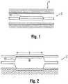
- angioplasty balloonsare expanded from a deflated, folded state to an expanded state within a vessel to treat a target area, such as a portion of the circumferential inner wall I of a blood vessel V, as shown in Figures 1 and 2 .
- the inflation of a balloon 12 with wall 28is traditionally completed using an X-ray contrast agent CM along dimension DX to provide better visibility under X-ray or other form of radiography R during the interventional procedure, as illustrated in Figures 3 and 3a (which shows the intensity measured by a fluoroscope detector plate, FDP).
- FDPfluoroscope detector plate
- a 70/30 percent mixture of contrast agent and salineis used to inflate the balloon during an angioplasty procedure.
- a desirable goalis to reduce inflation and deflation times required for balloons without sacrificing the profile of the balloons, especially for large volume balloons (which can require up to two minutes of inflation/deflation times with the contrast agent).
- the use of contrast agentprolongs the inflation/deflation times and also poses the risk of iodine exposure to patients sensitive to iodine.
- a non-radiopaque substancecould be used in lieu of the contrast agent, such as for example saline or carbon dioxide, but such substances are invisible during X-ray imaging, and thus do not enhance visibility.
- the physician performing the angioplasty procedureshould be able to locate the position of the uninflated balloon with accuracy, so that the balloon will be properly positioned once inflated. This is conventionally accomplished by attaching marker bands on the catheter shaft in the region corresponding to the balloon working surface.
- This "working surface”is the surface along the portion of the balloon that is used to achieve the desired treatment effect, such as contacting the calcified plaque (which surface in the case of a balloon having conical or tapering sections at the proximal and distal ends is typically co-extensive with a generally cylindrical barrel section).
- misalignment of the marker bands during placement along the shaftsometimes results in their failure to correspond precisely to the extent of the working surface, as is shown in Figure 4 (note misalignment amount X between each interior marker band M carried by shaft S and working surface W of balloon 12, which also typically includes a radiopaque tip P at the distal end).
- misalignment amount Xbetween each interior marker band M carried by shaft S and working surface W of balloon 12, which also typically includes a radiopaque tip P at the distal end.
- mismatchdue to several possible factors.
- One such factormay be the tolerance stack-ups arising as a consequence of the affixation of the balloon to the distal end of the catheter shaft.
- the balloonalso has a tendency to grow in the longitudinal direction when inflated, especially with large and particularly long balloons.
- Another factoris the tendency of the portion of the catheter shaft within the balloon to bend or flex during inflation. This may lead to misalignment between radiopaque markers fixed to the shaft and the working surface.
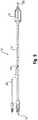
- the resulting misalignmentmay prevent the clinician from accurately identifying the location of the working surface of the balloon during an interventional procedure. This may lead to a geographic misplacement, or "miss," of the intended contact between the target area T and the working surface W of the balloon 12 (see Figure 2 ). It is especially desirable to avoid such an outcome when the balloon is designed to deliver a payload (such as a drug, stent, or both) or a working element to a specified location within the vasculature, since a miss may prolong the procedure (such as, for example, by requiring redeployment of the balloon 12 or the use of another balloon catheter in the case of a drug coated balloon).
- a payloadsuch as a drug, stent, or both
- the balloonmay also be subject to a phenomenon known as "pancaking." In this condition, the balloon 12 folds down upon itself to a flattened state, as shown in Figure 5 . This situation may cause the balloon to be viewed through fluoroscopy as perhaps still being in the inflated condition, since the full width of the balloon may still be perceived. This can give the clinician the false perception that the balloon remains inflated, when in fact it is not.
- the needis identified for a balloon for which the working surface may be identified during an interventional procedure with enhanced precision.
- the solutionwould take into account the possible mismatch between fixed locations on the catheter shaft and the balloon to define the working surface, and would operate independent of the position of the portion of the catheter shaft within the balloon.
- the improved identificationmay also allow for the better detection of the false perception of deflation caused by pancaking.
- procedural efficiencywould be enhanced without remarkably increasing cost or complexity, and in a manner that can be applied to many existing catheter technologies without extensive modification.
- US 2003/0055449 A1discloses medical devices which are formed at least in part of a polymeric material and a ferromagnetic or paramagnetic material, so that the medical device or component thereof is visible on magnetic resonance imaging scans.
- An object of the disclosureis to provide a balloon for which the working surface may be identified during an interventional procedure with enhanced precision.
- a catheter 10having a distal portion 11 with a balloon 12 mounted on a catheter tube 14.
- the balloon 12has an intermediate section 16, or "barrel,” and end sections 18, 20.
- the end sections 18, 20reduce in diameter to join the intermediate section 16 to the catheter tube 14 (and thus sections 18, 20 are generally termed cones or cone sections).
- the balloon 12is sealed at balloon ends (proximal end 15a and distal end 15b) on the cone sections 18, 20 to allow the inflation of the balloon 12 via one or more inflation lumens 17 extending within catheter tube 14 and communicating with the interior of the balloon 12.
- the catheter tube 14also includes an elongated, tubular shaft 24 forming a guidewire lumen 23 that directs the guidewire 26 through the catheter 10, and along the distal end of which the balloon 12 may be located.
- this guidewire 26may extend through the proximal end of the catheter 10, and a first port 25 of a connector 27 into the lumen 23 to achieve an "over the wire” (OTW) arrangement, but could also be provided in a "rapid exchange” (RX) configuration, in which the guidewire 26 exits a lateral opening 14a closer to the distal end (see Figure 9 ) or else is fed through the tip at a passage distally of the balloon 12 ("short" RX; not shown).
- a second port 29may also be associated with catheter 10, such as by way of connector 27, for introducing a fluid (e.g., saline, a contrast agent, or both) into the interior compartment of the balloon 12 via the inflation lumen 17.
- a fluide.g., saline, a contrast agent
- Balloon 12may include a single or multi-layered balloon wall 28 forming the interior for receiving the inflation fluid.
- the balloon 12may be a non-compliant balloon having a balloon wall 28 that maintains its size and shape in one or more directions when the balloon is inflated. Examples of non-compliant balloons may be found in U.S. Pat. No. 6,746,425 and Publication Nos. US 2006/0085022 , US 2006/0085023 and US 2006/0085024 .
- the balloon 12in such case also has a pre-determined surface area that remains constant during and after inflation, also has a pre-determined length and pre-determined diameter that each, or together, remain constant during and after inflation.
- the balloon 12could also be semi-compliant or compliant instead, depending on the particular use.
- the balloon 12may have a modified portion having a radiopaque quality.
- this radiopaque qualityis provided in a manner that allows for a clinician to differentiate, with relative ease and high precision, one portion of the balloon 12 from another (such as, but not limited to, the barrel section 16 including the working surface W from the cone sections 18, 20). This helps the clinician ensure the accurate positioning of the balloon 12 and, in particular, a portion of or the entire working surface W, at a specified treatment location, which may be especially desirable in the delivery of drugs via the balloon working surface W, as outlined in more detail in the following description.
- the radiopaque qualityis achieved by providing one or more at least partially radiopaque markings 30.
- the marking or markings 30may be provided along the balloon 12 to create a defined portion as the working surface W, as contrasted with the full length L of the balloon.
- a marking 30extend along the balloon 12 in a longitudinal direction along the barrel section 16 and over the entire circumference of the working surface W.
- the marking 30may extend over only a portion of the working surface W, or may extend over only a different part of the balloon 12 (such as the cone sections 18, 20), as outlined further in the following description.
- This marking 30may be provided during a process used to form the balloon 12 having the desired shape created by a multi-layered wall 28.
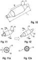
- a first tube 50comprising a thin layer of material (such as a polymer), may be inserted within a second tube 52, to form a parison 54, as shown in Figures 11 (perspective view) and 11a (cross-section).
- the second tube 52may also comprise a compatible polymeric material, but could also be formed of a different material (such as metal, including possibly a film).
- the second tube 52includes the one or more radiopaque markings 30, which may correspond in length to the barrel section 16 of the finished balloon, as shown in Figure 11 (but the second tube could extend the entire length of the balloon 12, as discussed below and illustrated by inner tube 62 in Figure 18 ).
- the first, inner tube 50may then be expanded to form a multi-layered balloon 12 ( Figure 12 ), with the second, outer tube 52 thus forming a radiopaque outer sleeve, as shown in the cross-sectional view of Figure 12a .
- this processingmay be achieved using a blow mold 54 having separable portions forming a mold cavity 56 corresponding in shape to the desired shape of the balloon.
- the outer tube 52may be pre-positioned in the mold cavity 56, including possibly within a correspondingly shaped recess formed along one or more of the interior surfaces of the mold 55.
- the inner tube 50may then be expanded using heat and pressure to form the balloon 12 with the desired shape, and having the outer tube 52 intimately bonded to it.
- Figure 14shows that, instead of a single tube 52, two spaced tubes, such as radiopaque collars 52a, 52b, may be provided on the inner tube 50 in order to provide spaced markings 30 on the finished balloon 12 (see Figure 19 ).
- these collars 52a, 52bmay be pre-positioned in the mold cavity 56 so as to receive the inner tube 50 when inserted.
- the collars 52, 52bmay be comprised of a thin flexible, material (e.g., a polymer, such as nylon) compatible with the material (e.g., a polymer, such as nylon) of the adjacent layer formed by tube 50, but could also be made of different materials, such as one or more metal foils.
- the collars 52a, 52bare intimately bonded to form a balloon 12 with spaced, radial markers, which as the result of the positioning at pre-determined locations in the mold cavity 56 may align precisely with the edges of the working surface W.
- the markings 30may be provided on the tube 52 (or tubes 52a, 52b) in various ways.
- the markings 30may be provided by applying a radiopaque material to the tube 52 at the desired location in any shape, pattern or form (including possibly alphanumeric characters to provide information that can be perceived under fluoroscopy, such as a length, diameter, logo, trademark, rated burst pressure, or balloon type). This may be done by inking, spraying, printing, or painting the radiopaque material in fluid form on the surface of the tube 52 (possibly with the application of a mask or the like, in which case the techniques of dipping or rolling in the radiopaque material to form the desired coating could be used).
- the marking 30may be embedded in the tube 52, including for example by providing it as part of a film, or in a bonding agent or adhesive used to bond multiple layers together to form the tube 52 (see, e.g., U.S. Patent Application Publication No. 2011/0160661 .
- the marking 30may be provided during the process of fabricating the tube 52, such as for example during a co-extrusion process. Examples of such techniques are described in a co-pending application filed on the same date as this application, "MEDICAL BALLOON WITH COEXTRUDED RADIOPAQUE PORTION,” listing as inventors Paul Fillmore, Justin Hall, Pat Byrne, Margo Underwood.
- the mold cavitymay be adapted to form the balloon 12 with the desired shape and appearance, and could also be adapted to form shoulders 12a on the balloon 12 once blown. These shoulders 12a may help to retain the outer tube 52 providing the modified portion of the balloon 12 against movement in the longitudinal direction, and thus help to ensure that it remains positioned at the desired location (again, in one embodiment, aligned with the full extent of the working surface W). Additionally or alternatively, as shown in Figure 17 , the inner surface of the outer tube 52 may be adapted for frictionally engaging the outer surface of the tube 50, such as by providing a roughened or textured surface 58.
- an adhesivemay be used to improve the bond between the tubes 50, 52.
- This adhesivemay be provided on either tube prior to blow molding.
- the adhesivemay also optionally be provided with a radiopacifier in order to enhance the radiopaque quality of the balloon 12 (see, e.g., U.S. Patent Application Publication No. 2011/0160661 ).
- a parison 60 in this embodimentmay include an inner layer comprising a radiopaque film 62, and an outer layer 64 comprising a traditional film that is not made radiopaque by an additive.
- the blow molding processexpands the parison 60 to thus form a balloon 12 having a radiopaque quality corresponding to the length of the inner layer including radiopacifier, which may be the full length L of the balloon 12.
- Balloons 12 that incorporate coatings comprising drugs to be applied to the vasculaturemay also benefit from the above-referenced embodiments.
- a balloon 12 including a defined working surface Wsuch as by providing radiopaque markings 30 at the transitions between the barrel section 16 and cone sections 18, 20, may include a portion coated with such a drug D, such as one designed for achieving a desired therapeutic effect when applied to the interior of the vessel.
- the radiopaque marking 30may also correspond to the location of the drug D on the balloon 12, such as along the entire working surface W or only a portion of it.
- the drug Dmay be applied to the inflated balloon as part of the manufacturing process, and prior to folding for insertion in the vasculature.
- the clinicianmay thus with the benefit of a fluoroscope determine the precise positioning of the working surface W prior to inflating the balloon 12 in the vasculature to deliver the drug D to the desired location and provide the desired treatment regi men.
- the markings 30may also be provided as one or more longitudinal strips 66 that do not extend along the entire circumference of the balloon 12, as shown in Figures 20 and 21 . This may be achieved by providing one or both of the layers 62, 64, or the tube 52, with radiopaque material corresponding to the strips 66, such as by a co-extrusion process.
- the blow molding operationmay be arranged to create a balloon 12 with a different type of modified layer.
- an insert 52may be provided with a functional modification, such as an outer surface that is textured or etched, and associated with an inner tube 50.
- the insert 52could be made partially or fully radiopaque if desired (see, e.g., Figure 10 ), but such is considered optional.
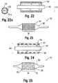
- a multi-layered insert 52may be provided with an outer radiopaque layer 51a and an inner support layer 51b that is not enhanced with a radiopacifier and exposed by the openings 53 formed by etchings in the outer layer (see Figure 22a ). This may create a particular pattern under fluoroscopy, which may allow for the detection of the locations on the balloon 12 where a drug is present (either on the etched portions or the unetched portions, as desired, which again may correspond to the working surface W).
- a balloon 12may be formed having an etched or textured outer surface layer 28a of the balloon wall 28.
- This layer 28amay extend along the entire working surface W, as shown in Figure 23 , or any portion of it.
- the material forming the insert 52should have a sufficiently high melt flow index such that the features are not caused to disappear as the result of the heat and pressure created during the blow molding process.
- the insert 52may be provided as a reticulated or fenestrated body, such as a mesh, screen or lattice having a plurality of crossing members 57 forming openings 53.
- the body 52may be tubular in form, as shown, and could comprise more than one piece or part (similar to collars 52a, 52b).
- the material forming the insert 52should have a sufficiently high melt flow index such that the features are not caused to disappear as the result of the heat and pressure created during the blow molding process.
- the insert 52bonds to an inner tube 50 and forms an outer layer of the finished balloon 12.
- the openings 53expose the balloon wall 28, which may be adapted to form the modified layer (such as by being radiopaque).
- the body 52may extend along the entire working surface W, and may optionally be fully or partially radiopaque. Alternatively, the body 52 may be provided with a coating, such as in the form of a drug or an agent providing enhanced lubricity.
- the mold 55may be modified to provide a surface treatment on the finished balloon 12.
- the inner surfaces of the mold cavity 56may be provided with a textured pattern 56a, such as by etching, engraving, or the like, so as to form inwardly directed projections. This includes along the portions corresponding to the working surface W of the balloon 12 (e.g., the barrel section).
- a parison 54which may be a single layer of material
- the surface of the resulting balloon 12is provided with a corresponding pattern in the form of an impression of the pattern in the mold 55.
- the projections forming the pattern 56a in the moldform depressions in the outer surface of the balloon wall 28.
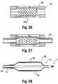
- An option in this embodimentis to deposit a material within the mold cavity 56 to partially or completely fill any spaces or gaps formed in the pattern 56a, such as for example a radiopacifier 59.
- a material within the mold cavity 56such as for example a radiopacifier 59.
- the balloon 12 resulting from blow molding using a mold 55 with this type of pattern 56a with a fillerwould thus have a surface layer modified to including the selected filler material (which in the case of a radiopacifier 59 would make the surface partially radiopaque, as shown by the darkened portions of the balloon wall 28 in Figure 28 ).
- the depositing of the material within the mold 55may be done by injection through an internal passageway opening within the cavity 56, either before or during the molding process, including possibly by spraying the filler material within the mold cavity 56 (such as when the mating portions forming the mold 55 are separated to expose the surface pattern 56a).
- radiopaque materialsinclude, but are not limited to, finely divided tungsten, tantalum, bismuth, bismuth trioxide, bismuth oxychloride, bismuth subcarbonate, other bismuth compounds, barium sulfate, tin, silver, silver compounds, rare earth oxides, and many other substances commonly used for X-ray absorption.
- the polymer used for making a film, possible with a radiopaque materialmay be any polymeric material which can be loaded with radiopacifier and formed into a sufficiently thin film. Examples of polymers include thermoplastic and thermoset polymers.
- thermoplastic polymersinclude, but are not limited to, polyurethanes, polyamides (nylon 11, nylon 12), polyether-polyamide copolymers such as PEBAX, polyethylene terephthalate or other polyesters, polyvinyl acetate, polyvinyl chloride, and many other thermoplastic materials useful for making films.
- thermoset polymersinclude, but are not limited to, crosslinked polyurethanes, polyureas, epoxies, acrylics, silicones, and many other thermoset materials that can be formed into thin structures, including films. Any adjacent structures to be bonded, such as tubes 50, 52 or layers 62, 64, may be formed of compatible materials, which may avoid additional processing or the inclusion of a compatibilizer, tie layer or the like.
Landscapes
- Health & Medical Sciences (AREA)
- Life Sciences & Earth Sciences (AREA)
- Engineering & Computer Science (AREA)
- Heart & Thoracic Surgery (AREA)
- Public Health (AREA)
- Animal Behavior & Ethology (AREA)
- Veterinary Medicine (AREA)
- General Health & Medical Sciences (AREA)
- Biomedical Technology (AREA)
- Child & Adolescent Psychology (AREA)
- Biophysics (AREA)
- Pulmonology (AREA)
- Anesthesiology (AREA)
- Hematology (AREA)
- Manufacturing & Machinery (AREA)
- Mechanical Engineering (AREA)
- Physics & Mathematics (AREA)
- Epidemiology (AREA)
- Optics & Photonics (AREA)
- Media Introduction/Drainage Providing Device (AREA)
- Blow-Moulding Or Thermoforming Of Plastics Or The Like (AREA)
Description
- This disclosure relates generally to a method for manufacturing balloons for performing medical procedures, such as angioplasty and, more particularly, to a parison for forming a blow molded medical balloon having a modified portion, such as a layer that is radiopaque, a medical balloon. Such a method is disclosed in the
US20090318848 . - Balloons are routinely used to resolve or address flow restrictions or perhaps even complete blockages in tubular areas of the body, such as arteries or veins. In many clinical situations, the restrictions are caused by hard solids, such as calcified plaque, and require the use of high pressures to compact such blockages. Commercially available balloons employ complex technology to achieve high pressure requirements without sacrificing the profile of the balloon. Besides high pressure requirements, the balloons should also be resistant to puncture, easy to track and push, and present a low profile, especially when used for angioplasty.
- In clinical practice, angioplasty balloons are expanded from a deflated, folded state to an expanded state within a vessel to treat a target area, such as a portion of the circumferential inner wall I of a blood vessel V, as shown in
Figures 1 and 2 . The inflation of aballoon 12 withwall 28 is traditionally completed using an X-ray contrast agent CM along dimension DX to provide better visibility under X-ray or other form of radiography R during the interventional procedure, as illustrated inFigures 3 and 3a (which shows the intensity measured by a fluoroscope detector plate, FDP). Typically, a 70/30 percent mixture of contrast agent and saline is used to inflate the balloon during an angioplasty procedure. - In general, a desirable goal is to reduce inflation and deflation times required for balloons without sacrificing the profile of the balloons, especially for large volume balloons (which can require up to two minutes of inflation/deflation times with the contrast agent). Because of its relatively high viscosity, it would also be desirable to eliminate, or at least reduce the amount of, the contrast agent used in inflation/deflation of the balloons. The use of contrast agent prolongs the inflation/deflation times and also poses the risk of iodine exposure to patients sensitive to iodine. In this regard, a non-radiopaque substance could be used in lieu of the contrast agent, such as for example saline or carbon dioxide, but such substances are invisible during X-ray imaging, and thus do not enhance visibility.
- Furthermore, the physician performing the angioplasty procedure should be able to locate the position of the uninflated balloon with accuracy, so that the balloon will be properly positioned once inflated. This is conventionally accomplished by attaching marker bands on the catheter shaft in the region corresponding to the balloon working surface. This "working surface" is the surface along the portion of the balloon that is used to achieve the desired treatment effect, such as contacting the calcified plaque (which surface in the case of a balloon having conical or tapering sections at the proximal and distal ends is typically co-extensive with a generally cylindrical barrel section).
- Misalignment of the marker bands during placement along the shaft sometimes results in their failure to correspond precisely to the extent of the working surface, as is shown in
Figure 4 (note misalignment amount X between each interior marker band M carried by shaft S and working surface W ofballoon 12, which also typically includes a radiopaque tip P at the distal end). Even upon exercising great care to position the markers properly on the underlying shaft in alignment with anticipated boundaries of the working surface when the balloon is inflated, there remains a tendency for mismatch due to several possible factors. One such factor may be the tolerance stack-ups arising as a consequence of the affixation of the balloon to the distal end of the catheter shaft. The balloon also has a tendency to grow in the longitudinal direction when inflated, especially with large and particularly long balloons. Another factor is the tendency of the portion of the catheter shaft within the balloon to bend or flex during inflation. This may lead to misalignment between radiopaque markers fixed to the shaft and the working surface. - Whatever the cause, the resulting misalignment may prevent the clinician from accurately identifying the location of the working surface of the balloon during an interventional procedure. This may lead to a geographic misplacement, or "miss," of the intended contact between the target area T and the working surface W of the balloon 12 (see
Figure 2 ). It is especially desirable to avoid such an outcome when the balloon is designed to deliver a payload (such as a drug, stent, or both) or a working element to a specified location within the vasculature, since a miss may prolong the procedure (such as, for example, by requiring redeployment of theballoon 12 or the use of another balloon catheter in the case of a drug coated balloon). - Upon deflation, the balloon may also be subject to a phenomenon known as "pancaking." In this condition, the
balloon 12 folds down upon itself to a flattened state, as shown inFigure 5 . This situation may cause the balloon to be viewed through fluoroscopy as perhaps still being in the inflated condition, since the full width of the balloon may still be perceived. This can give the clinician the false perception that the balloon remains inflated, when in fact it is not. - Accordingly, the need is identified for a balloon for which the working surface may be identified during an interventional procedure with enhanced precision. The solution would take into account the possible mismatch between fixed locations on the catheter shaft and the balloon to define the working surface, and would operate independent of the position of the portion of the catheter shaft within the balloon. The improved identification may also allow for the better detection of the false perception of deflation caused by pancaking. Overall, procedural efficiency would be enhanced without remarkably increasing cost or complexity, and in a manner that can be applied to many existing catheter technologies without extensive modification.
US 2003/0055449 A1 discloses medical devices which are formed at least in part of a polymeric material and a ferromagnetic or paramagnetic material, so that the medical device or component thereof is visible on magnetic resonance imaging scans.- The present invention is directed to the method of
claim 1. The dependent claims refer to preferred embodiments. An object of the disclosure is to provide a balloon for which the working surface may be identified during an interventional procedure with enhanced precision. Figures 1-9 are illustrative of the background of the invention;Figure 10 illustrates a first embodiment according to the disclosure;Figures 11-11a and 12-12a show a manufacturing technique for forming theFigure 10 embodiment;Figures 13 and 14 further show manufacturing techniques;Figure 15 illustrates a further embodiment according to the disclosure;Figures 16 and 17 illustrate another embodiment according to the disclosure;Figures 18-21 show still further embodiments;Figures 22 and 22a are cross-sectional side and end views of another embodiment;Figure 23 is a side view of a balloon catheter formed according to one aspect of the disclosure;Figures 24 and 25 show a further embodiment; andFigures 26-28 show still a further embodiment.- The description provided below and in regard to the figures applies to all embodiments unless noted otherwise, and features common to each embodiment are similarly shown and numbered.
- Provided is a
catheter 10 having adistal portion 11 with aballoon 12 mounted on acatheter tube 14. Referring toFigures 6, 7 , and8 , theballoon 12 has anintermediate section 16, or "barrel," andend sections end sections intermediate section 16 to the catheter tube 14 (and thussections balloon 12 is sealed at balloon ends (proximal end 15a anddistal end 15b) on thecone sections balloon 12 via one ormore inflation lumens 17 extending withincatheter tube 14 and communicating with the interior of theballoon 12. - The
catheter tube 14 also includes an elongated,tubular shaft 24 forming aguidewire lumen 23 that directs theguidewire 26 through thecatheter 10, and along the distal end of which theballoon 12 may be located. As illustrated inFigure 8 , thisguidewire 26 may extend through the proximal end of thecatheter 10, and afirst port 25 of aconnector 27 into thelumen 23 to achieve an "over the wire" (OTW) arrangement, but could also be provided in a "rapid exchange" (RX) configuration, in which theguidewire 26 exits alateral opening 14a closer to the distal end (seeFigure 9 ) or else is fed through the tip at a passage distally of the balloon 12 ("short" RX; not shown). Asecond port 29 may also be associated withcatheter 10, such as by way ofconnector 27, for introducing a fluid (e.g., saline, a contrast agent, or both) into the interior compartment of theballoon 12 via theinflation lumen 17. Balloon 12 may include a single ormulti-layered balloon wall 28 forming the interior for receiving the inflation fluid. Theballoon 12 may be a non-compliant balloon having aballoon wall 28 that maintains its size and shape in one or more directions when the balloon is inflated. Examples of non-compliant balloons may be found inU.S. Pat. No. 6,746,425 and Publication Nos.US 2006/0085022 ,US 2006/0085023 andUS 2006/0085024 . Theballoon 12 in such case also has a pre-determined surface area that remains constant during and after inflation, also has a pre-determined length and pre-determined diameter that each, or together, remain constant during and after inflation. Theballoon 12 could also be semi-compliant or compliant instead, depending on the particular use.- In order to provide for enhanced locatability during an interventional procedure, the
balloon 12 may have a modified portion having a radiopaque quality. In one embodiment, this radiopaque quality is provided in a manner that allows for a clinician to differentiate, with relative ease and high precision, one portion of theballoon 12 from another (such as, but not limited to, thebarrel section 16 including the working surface W from thecone sections 18, 20). This helps the clinician ensure the accurate positioning of theballoon 12 and, in particular, a portion of or the entire working surface W, at a specified treatment location, which may be especially desirable in the delivery of drugs via the balloon working surface W, as outlined in more detail in the following description. - In one embodiment, and with initial reference to
Figure 10 , the radiopaque quality is achieved by providing one or more at least partiallyradiopaque markings 30. The marking ormarkings 30 may be provided along theballoon 12 to create a defined portion as the working surface W, as contrasted with the full length L of the balloon. For example, a marking 30 extend along theballoon 12 in a longitudinal direction along thebarrel section 16 and over the entire circumference of the working surface W. Alternatively, the marking 30 may extend over only a portion of the working surface W, or may extend over only a different part of the balloon 12 (such as thecone sections 18, 20), as outlined further in the following description. - This marking 30 may be provided during a process used to form the
balloon 12 having the desired shape created by amulti-layered wall 28. In particular, afirst tube 50 comprising a thin layer of material (such as a polymer), may be inserted within asecond tube 52, to form aparison 54, as shown inFigures 11 (perspective view) and 11a (cross-section). Thesecond tube 52 may also comprise a compatible polymeric material, but could also be formed of a different material (such as metal, including possibly a film). Thesecond tube 52 includes the one or moreradiopaque markings 30, which may correspond in length to thebarrel section 16 of the finished balloon, as shown inFigure 11 (but the second tube could extend the entire length of theballoon 12, as discussed below and illustrated byinner tube 62 inFigure 18 ). The first,inner tube 50 may then be expanded to form a multi-layered balloon 12 (Figure 12 ), with the second,outer tube 52 thus forming a radiopaque outer sleeve, as shown in the cross-sectional view ofFigure 12a . - Turning to
Figure 13 , it can be understood that this processing may be achieved using ablow mold 54 having separable portions forming amold cavity 56 corresponding in shape to the desired shape of the balloon. Theouter tube 52 may be pre-positioned in themold cavity 56, including possibly within a correspondingly shaped recess formed along one or more of the interior surfaces of themold 55. Theinner tube 50 may then be expanded using heat and pressure to form theballoon 12 with the desired shape, and having theouter tube 52 intimately bonded to it. Figure 14 shows that, instead of asingle tube 52, two spaced tubes, such asradiopaque collars inner tube 50 in order to provide spacedmarkings 30 on the finished balloon 12 (seeFigure 19 ). Liketube 52, thesecollars mold cavity 56 so as to receive theinner tube 50 when inserted. As noted above fortube 52, thecollars tube 50, but could also be made of different materials, such as one or more metal foils. Upon expanding theinner tube 50, thecollars balloon 12 with spaced, radial markers, which as the result of the positioning at pre-determined locations in themold cavity 56 may align precisely with the edges of the working surface W.- The
markings 30 may be provided on the tube 52 (ortubes markings 30 may be provided by applying a radiopaque material to thetube 52 at the desired location in any shape, pattern or form (including possibly alphanumeric characters to provide information that can be perceived under fluoroscopy, such as a length, diameter, logo, trademark, rated burst pressure, or balloon type). This may be done by inking, spraying, printing, or painting the radiopaque material in fluid form on the surface of the tube 52 (possibly with the application of a mask or the like, in which case the techniques of dipping or rolling in the radiopaque material to form the desired coating could be used). Alternatively, the marking 30 may be embedded in thetube 52, including for example by providing it as part of a film, or in a bonding agent or adhesive used to bond multiple layers together to form the tube 52 (see, e.g.,U.S. Patent Application Publication No. 2011/0160661 . The marking 30 may be provided during the process of fabricating thetube 52, such as for example during a co-extrusion process. Examples of such techniques are described in a co-pending application filed on the same date as this application,"MEDICAL BALLOON WITH COEXTRUDED RADIOPAQUE PORTION," listing as inventors Paul Fillmore, Justin Hall, Pat Byrne, Margo Underwood. - As perhaps best understood with reference to
Figures 15 and16 , the mold cavity may be adapted to form theballoon 12 with the desired shape and appearance, and could also be adapted to formshoulders 12a on theballoon 12 once blown. Theseshoulders 12a may help to retain theouter tube 52 providing the modified portion of theballoon 12 against movement in the longitudinal direction, and thus help to ensure that it remains positioned at the desired location (again, in one embodiment, aligned with the full extent of the working surface W). Additionally or alternatively, as shown inFigure 17 , the inner surface of theouter tube 52 may be adapted for frictionally engaging the outer surface of thetube 50, such as by providing a roughened or texturedsurface 58. - Additionally or alternatively, an adhesive may be used to improve the bond between the
tubes U.S. Patent Application Publication No. 2011/0160661 ). - Another embodiment involves forming the
balloon 12 with a modified portion by blow molding a multi-layered parison, wherein at least one of the layers of the parison comprises a radiopaque material. Thus, for example, aparison 60 in this embodiment may include an inner layer comprising aradiopaque film 62, and anouter layer 64 comprising a traditional film that is not made radiopaque by an additive. The blow molding process expands theparison 60 to thus form aballoon 12 having a radiopaque quality corresponding to the length of the inner layer including radiopacifier, which may be the full length L of theballoon 12. Balloons 12 that incorporate coatings comprising drugs to be applied to the vasculature may also benefit from the above-referenced embodiments. For example, as shown inFigure 19 , aballoon 12 including a defined working surface W, such as by providingradiopaque markings 30 at the transitions between thebarrel section 16 andcone sections radiopaque marking 30 may also correspond to the location of the drug D on theballoon 12, such as along the entire working surface W or only a portion of it. The drug D may be applied to the inflated balloon as part of the manufacturing process, and prior to folding for insertion in the vasculature. The clinician may thus with the benefit of a fluoroscope determine the precise positioning of the working surface W prior to inflating theballoon 12 in the vasculature to deliver the drug D to the desired location and provide the desired treatment regi men.- The
markings 30 may also be provided as one or morelongitudinal strips 66 that do not extend along the entire circumference of theballoon 12, as shown inFigures 20 and 21 . This may be achieved by providing one or both of thelayers tube 52, with radiopaque material corresponding to thestrips 66, such as by a co-extrusion process. Additional details are provided in a concurrently filed patent applications entitled,"MEDICAL BALLOON WITH RADIOPAQUE IDENTIFIER FOR PRECISELY IDENTIFYING THE WORKING SURFACE," for inventors Scan Wall, Pat Byrne, Robert Righi, Angela Crall, Paul Wales, and Allan Ronan, and"MEDICAL BALLOON WITH RADIOPAQUE END PORTION FOR PRECISELY IDENTIFYING A WORKING SURFACE LOCATION," for inventors Sean Wall, Scott Randall, Robert Righi, Angela Crall. The presence of plural spacedmarkings 30 in this manner may also help to distinguish between the inflated condition (in which the markings are spaced), and the properly deflated condition, as the markings would be closer to each other when the balloon is folded. - In another embodiment, the blow molding operation may be arranged to create a
balloon 12 with a different type of modified layer. For example, inFigure 22 , aninsert 52 may be provided with a functional modification, such as an outer surface that is textured or etched, and associated with aninner tube 50. Theinsert 52 could be made partially or fully radiopaque if desired (see, e.g.,Figure 10 ), but such is considered optional. In one embodiment, amulti-layered insert 52 may be provided with an outerradiopaque layer 51a and aninner support layer 51b that is not enhanced with a radiopacifier and exposed by theopenings 53 formed by etchings in the outer layer (seeFigure 22a ). This may create a particular pattern under fluoroscopy, which may allow for the detection of the locations on theballoon 12 where a drug is present (either on the etched portions or the unetched portions, as desired, which again may correspond to the working surface W). - In any case, on blow molding the resulting
parison 54 into a corresponding mold 55 (seeFigures 13 and 14 ), aballoon 12 may be formed having an etched or textured outer surface layer 28a of theballoon wall 28. This layer 28a may extend along the entire working surface W, as shown inFigure 23 , or any portion of it. In the case of etching, texturing, or other surface features, the material forming theinsert 52 should have a sufficiently high melt flow index such that the features are not caused to disappear as the result of the heat and pressure created during the blow molding process. - Another example for creating a
balloon 12 with a modified layer is to provide aninsert 52 with one or more openings. For example, as shown inFigure 24 , theinsert 52 may be provided as a reticulated or fenestrated body, such as a mesh, screen or lattice having a plurality of crossingmembers 57 formingopenings 53. Thebody 52 may be tubular in form, as shown, and could comprise more than one piece or part (similar tocollars insert 52 should have a sufficiently high melt flow index such that the features are not caused to disappear as the result of the heat and pressure created during the blow molding process. - When arranged to form a
parsion 54 and blow molded together, theinsert 52 bonds to aninner tube 50 and forms an outer layer of thefinished balloon 12. In the case of aninsert 52 as shown, theopenings 53 expose theballoon wall 28, which may be adapted to form the modified layer (such as by being radiopaque). Thebody 52 may extend along the entire working surface W, and may optionally be fully or partially radiopaque. Alternatively, thebody 52 may be provided with a coating, such as in the form of a drug or an agent providing enhanced lubricity. - It is also possible to modify the
mold 55 to provide a surface treatment on thefinished balloon 12. For example, as shown inFigure 25 , the inner surfaces of themold cavity 56 may be provided with atextured pattern 56a, such as by etching, engraving, or the like, so as to form inwardly directed projections. This includes along the portions corresponding to the working surface W of the balloon 12 (e.g., the barrel section). When a parison 54 (which may be a single layer of material), is then expanded in the mold cavity 56 (Figure 26 ), the surface of the resultingballoon 12 is provided with a corresponding pattern in the form of an impression of the pattern in themold 55. In other words, the projections forming thepattern 56a in the mold form depressions in the outer surface of theballoon wall 28. - An option in this embodiment is to deposit a material within the
mold cavity 56 to partially or completely fill any spaces or gaps formed in thepattern 56a, such as for example aradiopacifier 59. As shown inFigures 27 and 28 , theballoon 12 resulting from blow molding using amold 55 with this type ofpattern 56a with a filler would thus have a surface layer modified to including the selected filler material (which in the case of aradiopacifier 59 would make the surface partially radiopaque, as shown by the darkened portions of theballoon wall 28 inFigure 28 ). The depositing of the material within themold 55 may be done by injection through an internal passageway opening within thecavity 56, either before or during the molding process, including possibly by spraying the filler material within the mold cavity 56 (such as when the mating portions forming themold 55 are separated to expose thesurface pattern 56a). - Examples of radiopaque materials include, but are not limited to, finely divided tungsten, tantalum, bismuth, bismuth trioxide, bismuth oxychloride, bismuth subcarbonate, other bismuth compounds, barium sulfate, tin, silver, silver compounds, rare earth oxides, and many other substances commonly used for X-ray absorption. The polymer used for making a film, possible with a radiopaque material, may be any polymeric material which can be loaded with radiopacifier and formed into a sufficiently thin film. Examples of polymers include thermoplastic and thermoset polymers. Some examples of thermoplastic polymers include, but are not limited to, polyurethanes, polyamides (
nylon 11, nylon 12), polyether-polyamide copolymers such as PEBAX, polyethylene terephthalate or other polyesters, polyvinyl acetate, polyvinyl chloride, and many other thermoplastic materials useful for making films. Some examples of thermoset polymers include, but are not limited to, crosslinked polyurethanes, polyureas, epoxies, acrylics, silicones, and many other thermoset materials that can be formed into thin structures, including films. Any adjacent structures to be bonded, such astubes layers
Claims (6)
- A method of manufacturing a medical balloon (12) using a mold (55) having a mold cavity (56), comprising:blow molding a parison (54) at least partially within the mold cavity (56) of the mold (55) to form a balloon (12) having a modified outer portion along a working surface (W) of the balloon (12),wherein the mold cavity (56) includes a surface pattern (56a) and a filler material, and the blow molding step creates the modified portion by contacting the parison (54) with the surface pattern (56a) and the filler material.
- The method of claim 1, wherein the blow molding step is preceded by the step of providing a material for forming the modified portion in the blow mold.
- The method of claim 1 or 2, wherein the blow molding step is preceded by the step of providing a tube for forming the modified portion in the blow mold.
- The method of any of claims 1 to 3, wherein the blow molding step is preceded by the step of providing a fenestrated tube for forming the modified portion in the blow mold.
- The method of any of claims 1 to 4, wherein the blow molding step is preceded by the step of providing a reticulated tube for forming the modified portion in the blow mold.
- The method of any of claims 1 to 5, wherein the mold cavity (56) includes a surface pattern (56a) and a radiopaque material (59), and the blow molding step creates the modified portion by contacting the parison (54) with the surface pattern (56a) and the radiopaque material (59).
Applications Claiming Priority (4)
| Application Number | Priority Date | Filing Date | Title |
|---|---|---|---|
| US201261608908P | 2012-03-09 | 2012-03-09 | |
| NL2008445 | 2012-03-09 | ||
| EP13716873.8AEP2822633B1 (en) | 2012-03-09 | 2013-03-08 | Parison for forming blow molded medical balloon with modified portion, medical balloon, and related methods |
| PCT/US2013/029974WO2013134696A1 (en) | 2012-03-09 | 2013-03-08 | Parison for forming blow molded medical balloon with midified portion, medical balloon, and related methods |
Related Parent Applications (1)
| Application Number | Title | Priority Date | Filing Date |
|---|---|---|---|
| EP13716873.8ADivisionEP2822633B1 (en) | 2012-03-09 | 2013-03-08 | Parison for forming blow molded medical balloon with modified portion, medical balloon, and related methods |
Publications (2)
| Publication Number | Publication Date |
|---|---|
| EP3495013A1 EP3495013A1 (en) | 2019-06-12 |
| EP3495013B1true EP3495013B1 (en) | 2020-11-18 |
Family
ID=49117403
Family Applications (2)
| Application Number | Title | Priority Date | Filing Date |
|---|---|---|---|
| EP13716873.8AActiveEP2822633B1 (en) | 2012-03-09 | 2013-03-08 | Parison for forming blow molded medical balloon with modified portion, medical balloon, and related methods |
| EP19152758.9AActiveEP3495013B1 (en) | 2012-03-09 | 2013-03-08 | Parison for forming blow molded medical balloon with modified portion, medical balloon, and related methods |
Family Applications Before (1)
| Application Number | Title | Priority Date | Filing Date |
|---|---|---|---|
| EP13716873.8AActiveEP2822633B1 (en) | 2012-03-09 | 2013-03-08 | Parison for forming blow molded medical balloon with modified portion, medical balloon, and related methods |
Country Status (8)
| Country | Link |
|---|---|
| US (3) | US11357956B2 (en) |
| EP (2) | EP2822633B1 (en) |
| JP (2) | JP6313230B2 (en) |
| KR (1) | KR102182896B1 (en) |
| CN (1) | CN104245035A (en) |
| AU (1) | AU2013229825A1 (en) |
| IN (1) | IN2014DN07123A (en) |
| WO (1) | WO2013134696A1 (en) |
Families Citing this family (12)
| Publication number | Priority date | Publication date | Assignee | Title |
|---|---|---|---|---|
| JP6220355B2 (en) | 2012-03-09 | 2017-10-25 | クリアストリーム・テクノロジーズ・リミテッド | Medical balloon with a radiopaque end portion for accurately identifying the location of the working surface |
| US10500378B2 (en) | 2012-03-09 | 2019-12-10 | Clearstream Technologies Limited | Medical balloon including radiopaque insert for precisely identifying a working surface location |
| IN2014DN07123A (en) | 2012-03-09 | 2015-04-24 | Clearstream Tech Ltd | |
| US10668257B2 (en) | 2014-10-16 | 2020-06-02 | W. L. Gore & Associates, Inc. | Blow molded composite devices and methods |
| EP3727553B1 (en)* | 2018-01-03 | 2021-11-24 | C.R. Bard, Inc. | Methods of manufacturing a balloon with integral scoring element |
| JP7369182B2 (en)* | 2019-03-22 | 2023-10-25 | 株式会社カネカ | Balloon catheter manufacturing method |
| CN110975112B (en)* | 2019-12-17 | 2022-02-08 | 禾木(中国)生物工程有限公司 | Preparation method of balloon catheter |
| CN112793172B (en)* | 2020-12-21 | 2022-07-15 | 科塞尔医疗科技(苏州)有限公司 | Balloon forming device suitable for forming different special balloons |
| US12251130B2 (en) | 2021-05-03 | 2025-03-18 | Covidien Lp | Surgical access device having a balloon and methods for manufacturing the same |
| CN112971915B (en)* | 2021-05-08 | 2021-08-20 | 上海百心安生物技术股份有限公司 | A pulsed balloon and its application |
| CN119403590A (en)* | 2022-11-30 | 2025-02-07 | 株式会社戈德曼 | Balloon catheter and method for manufacturing balloon catheter |
| US20250269402A1 (en)* | 2024-02-22 | 2025-08-28 | Illuminoss Medical, Inc. | Systems and methods for inking a catheter balloon |
Citations (3)
| Publication number | Priority date | Publication date | Assignee | Title |
|---|---|---|---|---|
| US5041125A (en)* | 1989-01-26 | 1991-08-20 | Cordis Corporation | Balloon catheter |
| WO2009146280A1 (en)* | 2008-05-29 | 2009-12-03 | Boston Scientific Scimed, Inc. | Multi-layer balloon design for use in combination with catheter assemblies, and methods of making the same |
| US20090318848A1 (en)* | 2008-06-20 | 2009-12-24 | Boston Scientific Scimed, Inc. | Medical devices employing conductive polymers for delivery of therapeutic agents |
Family Cites Families (107)
| Publication number | Priority date | Publication date | Assignee | Title |
|---|---|---|---|---|
| US4047868A (en) | 1975-08-12 | 1977-09-13 | Toppan Printing Co., Ltd. | Multilayer parison extrusion molding machine for blow molding |
| US4276874A (en) | 1978-11-15 | 1981-07-07 | Datascope Corp. | Elongatable balloon catheter |
| US4292974A (en) | 1980-01-30 | 1981-10-06 | Thomas J. Fogarty | Dilatation catheter apparatus and method |
| WO1988000844A1 (en) | 1986-08-08 | 1988-02-11 | Scimed Life Systems, Inc. | Angioplasty dilating guide wire |
| US5358486A (en) | 1987-01-09 | 1994-10-25 | C. R. Bard, Inc. | Multiple layer high strength balloon for dilatation catheter |
| JPH01145074A (en) | 1987-12-01 | 1989-06-07 | Terumo Corp | Balloon catheter |
| US5085636A (en) | 1989-01-13 | 1992-02-04 | Scimed Life Systems, Inc. | Balloon catheter with inflation-deflation valve |
| DE69002295T2 (en)* | 1989-09-25 | 1993-11-04 | Schneider Usa Inc | MULTILAYER EXTRUSION AS A METHOD FOR PRODUCING BALLOONS FOR VESSEL PLASTICS. |
| US5209730A (en) | 1989-12-19 | 1993-05-11 | Scimed Life Systems, Inc. | Method for placement of a balloon dilatation catheter across a stenosis and apparatus therefor |
| AU7524391A (en)* | 1990-05-15 | 1991-11-21 | C.R. Bard Inc. | Multiple layer high strength balloon for dilatation catheter |
| US6004289A (en) | 1990-05-15 | 1999-12-21 | Medtronic Ave, Inc. | Multiple layer high strength balloon for dilatation catheter |
| WO1993020876A1 (en) | 1992-04-14 | 1993-10-28 | Du-Med B.V. | Electronic catheter displacement sensor |
| US5948489A (en) | 1994-03-03 | 1999-09-07 | Cordis Corporation | Catheter having extruded, flexible, pliable and compliant marker band |
| US5587125A (en)* | 1994-08-15 | 1996-12-24 | Schneider (Usa) Inc. | Non-coextrusion method of making multi-layer angioplasty balloons |
| US5549551A (en) | 1994-12-22 | 1996-08-27 | Advanced Cardiovascular Systems, Inc. | Adjustable length balloon catheter |
| EP0723786A1 (en) | 1995-01-30 | 1996-07-31 | Cardiovascular Concepts, Inc. | Lesion measurement catheter and method |
| US6124007A (en)* | 1996-03-06 | 2000-09-26 | Scimed Life Systems Inc | Laminate catheter balloons with additive burst strength and methods for preparation of same |
| JPH09327515A (en) | 1996-06-07 | 1997-12-22 | Toshio Takeshima | Film with x-ray non-transmissive marker |
| US6746425B1 (en) | 1996-06-14 | 2004-06-08 | Futuremed Interventional | Medical balloon |
| US5779731A (en) | 1996-12-20 | 1998-07-14 | Cordis Corporation | Balloon catheter having dual markers and method |
| US5851210A (en) | 1997-03-21 | 1998-12-22 | Torossian; Richard | Stent delivery system and method |
| DE19739086C1 (en) | 1997-09-06 | 1999-07-15 | Voelker Wolfram Priv Doz Dr Me | Balloon catheter |
| JP2000070375A (en)* | 1998-09-01 | 2000-03-07 | Togo Medikit Kk | Marker laminated balloon catheter |
| US6786889B1 (en)* | 1999-03-31 | 2004-09-07 | Scimed Life Systems, Inc | Textured and/or marked balloon for stent delivery |
| US6325780B1 (en) | 1999-09-13 | 2001-12-04 | Advanced Cardiovascular Systems, Inc. | Inflatable member formed of liquid crystal polymeric material blend |
| US6695809B1 (en) | 1999-09-13 | 2004-02-24 | Advanced Cardiovascular Systems, Inc. | Catheter balloon with a discontinuous elastomeric outer layer |
| US6977103B2 (en)* | 1999-10-25 | 2005-12-20 | Boston Scientific Scimed, Inc. | Dimensionally stable balloons |
| EP1743664B1 (en) | 1999-10-25 | 2009-12-16 | Boston Scientific Limited | Dimensionally stable balloons |
| GB2355797A (en) | 1999-10-26 | 2001-05-02 | Anthony James Ivor Scriven | A guidewire having measurement markings |
| DE19952505A1 (en) | 1999-10-29 | 2001-05-03 | Gerd Hausdorf | An expandable balloon for medical use comprises a thin-walled polymer shell coated with radio-opaque material in a pattern and is expandable on introduction of liquid and increasing pressure |
| US6652568B1 (en)* | 1999-12-22 | 2003-11-25 | Advanced Cardiovascular Systems, Inc. | Radiopaque balloon |
| US6540721B1 (en) | 1999-12-29 | 2003-04-01 | Advanced Cardiovascular Systems, Inc. | Balloon catheter with flexible radiopaque polymeric marker |
| US6520934B1 (en) | 1999-12-29 | 2003-02-18 | Advanced Cardiovascular Systems, Inc. | Catheter assemblies with flexible radiopaque marker |
| US6756094B1 (en)* | 2000-02-28 | 2004-06-29 | Scimed Life Systems, Inc. | Balloon structure with PTFE component |
| US6884257B1 (en) | 2000-11-28 | 2005-04-26 | Advanced Cardiovascular Systems, Inc. | Stent delivery system with adjustable length balloon |
| US20020198559A1 (en) | 2001-06-26 | 2002-12-26 | Bhavesh Mistry | Radiopaque balloon |
| US20030009151A1 (en) | 2001-07-03 | 2003-01-09 | Scimed Life Systems, Inc. | Biaxially oriented multilayer polymer tube for medical devices |
| US6946092B1 (en)* | 2001-09-10 | 2005-09-20 | Scimed Life Systems, Inc. | Medical balloon |
| US6911017B2 (en)* | 2001-09-19 | 2005-06-28 | Advanced Cardiovascular Systems, Inc. | MRI visible catheter balloon |
| US6884234B2 (en) | 2001-11-01 | 2005-04-26 | Cardio Exodus Partners | Foldable and remotely imageable balloon |
| US20040236366A1 (en) | 2002-05-16 | 2004-11-25 | Kennedy Kenneth C. | Non-buckling balloon catheter |
| US7758604B2 (en) | 2003-05-29 | 2010-07-20 | Boston Scientific Scimed, Inc. | Cutting balloon catheter with improved balloon configuration |
| US20050215950A1 (en) | 2004-03-26 | 2005-09-29 | Scimed Life Systems, Inc. | Balloon catheter with radiopaque portion |
| US20110004057A1 (en) | 2004-04-21 | 2011-01-06 | Acclarent, Inc. | Systems and methods for transnasal dilation of passageways in the ear, nose or throat |
| US7717951B2 (en) | 2004-05-06 | 2010-05-18 | Cook Incorporated | Delivery system that facilitates visual inspection of an intraluminal medical device |
| US7491188B2 (en) | 2004-10-12 | 2009-02-17 | Boston Scientific Scimed, Inc. | Reinforced and drug-eluting balloon catheters and methods for making same |
| US7682335B2 (en) | 2004-10-15 | 2010-03-23 | Futurematrix Interventional, Inc. | Non-compliant medical balloon having an integral non-woven fabric layer |
| US7354419B2 (en) | 2004-10-15 | 2008-04-08 | Futuremed Interventional, Inc. | Medical balloon having strengthening rods |
| US7309324B2 (en) | 2004-10-15 | 2007-12-18 | Futuremed Interventional, Inc. | Non-compliant medical balloon having an integral woven fabric layer |
| US8597260B2 (en)* | 2004-12-16 | 2013-12-03 | Smiths Medical Asd, Inc. | Catheter with direction orientation |
| US20060165926A1 (en) | 2005-01-27 | 2006-07-27 | Jan Weber | Medical devices including nanocomposites |
| US20080188803A1 (en) | 2005-02-03 | 2008-08-07 | Jang G David | Triple-profile balloon catheter |
| US20060182873A1 (en) | 2005-02-17 | 2006-08-17 | Klisch Leo M | Medical devices |
| US7462684B2 (en)* | 2005-03-02 | 2008-12-09 | Eastman Chemical Company | Preparation of transparent, multilayered articles containing polyesters comprising a cyclobutanediol and homogeneous polyamide blends |
| US20070100280A1 (en) | 2005-03-31 | 2007-05-03 | Van Sloten Leonard A | Catheter with balloon material having visual marker |
| US7195612B2 (en) | 2005-03-31 | 2007-03-27 | Gordis Corporation | Esophageal balloon catheter with visual marker |
| US20080228138A1 (en) | 2005-03-31 | 2008-09-18 | Van Sloten Leonard A | Catheter with balloon having visual marker |
| US7763198B2 (en)* | 2005-04-12 | 2010-07-27 | Abbott Cardiovascular Systems Inc. | Method for retaining a vascular stent on a catheter |
| US9352133B2 (en) | 2005-06-09 | 2016-05-31 | Boston Scientific Scimed, Inc. | Balloon catheters with increased column strength |
| EP1896110B1 (en) | 2005-06-10 | 2009-10-21 | Cook Incorporated | Balloon catheter that resists curving |
| JP4707140B2 (en) | 2005-07-15 | 2011-06-22 | 朝日インテック株式会社 | Medical treatment tool |
| US20070038290A1 (en)* | 2005-08-15 | 2007-02-15 | Bin Huang | Fiber reinforced composite stents |
| US8197505B2 (en) | 2005-10-14 | 2012-06-12 | Endocross Ltd. | Balloon catheter system for treating vascular occlusions |
| US8876763B2 (en) | 2005-11-01 | 2014-11-04 | Boston Scientific Scimed, Inc. | Composite balloon |
| CA2626598A1 (en)* | 2005-11-09 | 2007-05-18 | C.R. Bard Inc. | Grafts and stent grafts having a radiopaque marker |
| EP1948288B1 (en) | 2005-11-14 | 2009-12-23 | Abbott Laboratories Vascular Enterprises Limited | Balloon catheter with elastic segment |
| US8685074B2 (en) | 2005-11-18 | 2014-04-01 | Boston Scientific Scimed, Inc. | Balloon catheter |
| US7828766B2 (en)* | 2005-12-20 | 2010-11-09 | Advanced Cardiovascular Systems, Inc. | Non-compliant multilayered balloon for a catheter |
| WO2007094374A1 (en) | 2006-02-15 | 2007-08-23 | Sekisui Chemical Co., Ltd. | Balloon catheter |
| US8043673B2 (en)* | 2006-03-02 | 2011-10-25 | Boston Scientific Scimed, Inc. | Method to make tube-in-tube balloon |
| US7520876B2 (en) | 2006-04-21 | 2009-04-21 | Entellus Medical, Inc. | Device and method for treatment of sinusitis |
| WO2007132447A2 (en) | 2006-05-11 | 2007-11-22 | Y Med Inc. | Systems and methods for treating a vessel using focused force |
| US20080045896A1 (en) | 2006-08-17 | 2008-02-21 | Abott Laboratories | Catheter having intermediate position markers |
| US7896840B2 (en) | 2007-04-05 | 2011-03-01 | Boston Scientific Scimed, Inc. | Catheter having internal mechanisms to encourage balloon re-folding |
| WO2009009474A1 (en) | 2007-07-09 | 2009-01-15 | Wilson-Cook Medical Inc. | Balloon catheter with deflation mechanism |
| ATE535277T1 (en) | 2007-07-09 | 2011-12-15 | Cook Medical Technologies Llc | FOLDING CONTROL MECHANISM FOR A BALLOON |
| DE102008008925A1 (en)* | 2008-02-13 | 2009-08-20 | Biotronik Vi Patent Ag | Catheter, intraluminal endoprosthesis delivery system, and method of making the same |
| WO2009114425A1 (en)* | 2008-03-13 | 2009-09-17 | Cook Incorporated | Cutting balloon with connector and dilation element |
| US20090299374A1 (en)* | 2008-06-02 | 2009-12-03 | Loma Vista Medical, Inc. | Inflatable medical devices |
| CA2729750C (en) | 2008-07-03 | 2017-06-06 | Hotspur Technologies, Inc. | Apparatus and method comprising an expandable balloon or member for treating obstructions within body lumens |
| US9067045B2 (en) | 2008-07-25 | 2015-06-30 | Cook Medical Technologies Llc | Balloon catheter and method for making same |
| CA2736084C (en) | 2008-09-05 | 2018-01-02 | Richard Elton | Balloon with radiopaque adhesive |
| JP2012507372A (en) | 2008-10-30 | 2012-03-29 | アール4 バスキュラー インコーポレイテッド | Fracture resistant compliant radiopaque catheter balloon and method for using it in endovascular surgical procedures |
| US8052638B2 (en) | 2008-11-26 | 2011-11-08 | Abbott Cardiovascular Systems, Inc. | Robust multi-layer balloon |
| US20100158193A1 (en)* | 2008-12-22 | 2010-06-24 | Bates Mark C | Interventional Devices Formed Using Compositions Including Metal-Coated Nanotubes Dispersed In Polymers, And Methods Of Making And Using Same |
| US8562885B2 (en)* | 2009-02-21 | 2013-10-22 | Dow Global Technologies Inc. | Multilayer structures having annular profiles and methods and apparatus of making the same |
| US8298218B2 (en) | 2009-07-29 | 2012-10-30 | Medtronic Cryocath Lp | Compliant balloon |
| US8814775B2 (en) | 2010-03-18 | 2014-08-26 | Cianna Medical, Inc. | Expandable brachytherapy apparatus and methods for using them |
| US20110264185A1 (en)* | 2010-04-21 | 2011-10-27 | Thomas Haslinger | Balloon catheter and balloon mold to facilitate marker placement and method for using same |
| US8585959B2 (en) | 2010-09-30 | 2013-11-19 | Cook Medical Technologies Llc | Balloon with integrally retained dilation element |
| GB2485769B (en) | 2010-11-22 | 2012-12-05 | Cook Medical Technologies Llc | Scoring balloon and method of making same |
| US20120232528A1 (en) | 2011-03-07 | 2012-09-13 | Abbott Cardiovascular Systems Inc. | Delivery system with incremental markers |
| US20130030406A1 (en)* | 2011-07-26 | 2013-01-31 | Medtronic Vascular, Inc. | Textured Dilatation Balloon and Methods |
| GB2494113B (en)* | 2011-08-25 | 2013-07-17 | Cook Medical Technologies Llc | Medical balloon and balloon catheter assembly |
| GB2494395B (en) | 2011-09-02 | 2014-01-08 | Cook Medical Technologies Llc | Ultrasonically visible scoring balloon |
| CN107281617A (en) | 2012-03-09 | 2017-10-24 | 明讯科技有限公司 | Foley's tube with expandable axle |
| KR20140133548A (en) | 2012-03-09 | 2014-11-19 | 클리어스트림 테크놀러지스 리미티드 | Medical balloon with multi-position actuator for precisely arranging the working surface |
| EP2822630A2 (en) | 2012-03-09 | 2015-01-14 | Clearstream Technologies Limited | Medical balloon including variable radiopaque qualities for precisely identifying a working surface location |
| JP6220355B2 (en) | 2012-03-09 | 2017-10-25 | クリアストリーム・テクノロジーズ・リミテッド | Medical balloon with a radiopaque end portion for accurately identifying the location of the working surface |
| AU2013229837B2 (en) | 2012-03-09 | 2017-05-11 | Clearstream Technologies Limited | Medical balloon with a precisely identifiable portion |
| CN104245038B (en) | 2012-03-09 | 2017-05-31 | 明讯科技有限公司 | Medical balloon with co-extruded radiopaque portion |
| IN2014DN07123A (en) | 2012-03-09 | 2015-04-24 | Clearstream Tech Ltd | |
| AU2013229378A1 (en) | 2012-03-09 | 2014-09-25 | Clearstream Technologies Limited | Medical balloon including a radiopaque wire for precisely identifying a working surface location |
| US10500378B2 (en) | 2012-03-09 | 2019-12-10 | Clearstream Technologies Limited | Medical balloon including radiopaque insert for precisely identifying a working surface location |
| US20150105722A1 (en) | 2012-03-09 | 2015-04-16 | Clearstream Technologies Limited | Balloon catheter with floating hub |
| IN2014DN07116A (en) | 2012-03-09 | 2015-04-24 | Clearstream Tech Ltd | |
| GB2501065B (en) | 2012-03-27 | 2014-09-03 | Cook Medical Technologies Llc | Medical balloon with textured or roughened outer layer |
- 2013
- 2013-03-08ININ7123DEN2014patent/IN2014DN07123A/enunknown
- 2013-03-08USUS14/383,764patent/US11357956B2/enactiveActive
- 2013-03-08AUAU2013229825Apatent/AU2013229825A1/ennot_activeAbandoned
- 2013-03-08CNCN201380020467.6Apatent/CN104245035A/enactivePending
- 2013-03-08JPJP2014561159Apatent/JP6313230B2/enactiveActive
- 2013-03-08WOPCT/US2013/029974patent/WO2013134696A1/enactiveApplication Filing
- 2013-03-08EPEP13716873.8Apatent/EP2822633B1/enactiveActive
- 2013-03-08EPEP19152758.9Apatent/EP3495013B1/enactiveActive
- 2013-03-08KRKR1020147024841Apatent/KR102182896B1/enactiveActive
- 2018
- 2018-01-15JPJP2018004260Apatent/JP6709805B2/enactiveActive
- 2021
- 2021-10-08USUS17/496,869patent/US11685097B2/enactiveActive
- 2022
- 2022-05-11USUS17/741,808patent/US11919222B2/enactiveActive
Patent Citations (3)
| Publication number | Priority date | Publication date | Assignee | Title |
|---|---|---|---|---|
| US5041125A (en)* | 1989-01-26 | 1991-08-20 | Cordis Corporation | Balloon catheter |
| WO2009146280A1 (en)* | 2008-05-29 | 2009-12-03 | Boston Scientific Scimed, Inc. | Multi-layer balloon design for use in combination with catheter assemblies, and methods of making the same |
| US20090318848A1 (en)* | 2008-06-20 | 2009-12-24 | Boston Scientific Scimed, Inc. | Medical devices employing conductive polymers for delivery of therapeutic agents |
Also Published As
| Publication number | Publication date |
|---|---|
| US11685097B2 (en) | 2023-06-27 |
| CN104245035A (en) | 2014-12-24 |
| JP6709805B2 (en) | 2020-06-17 |
| US20150105723A1 (en) | 2015-04-16 |
| KR102182896B1 (en) | 2020-11-26 |
| EP3495013A1 (en) | 2019-06-12 |
| IN2014DN07123A (en) | 2015-04-24 |
| AU2013229825A1 (en) | 2014-09-25 |
| JP2018075446A (en) | 2018-05-17 |
| EP2822633B1 (en) | 2019-02-06 |
| EP2822633A1 (en) | 2015-01-14 |
| US11357956B2 (en) | 2022-06-14 |
| US20220023601A1 (en) | 2022-01-27 |
| KR20140133842A (en) | 2014-11-20 |
| JP6313230B2 (en) | 2018-04-18 |
| WO2013134696A1 (en) | 2013-09-12 |
| US20220266499A1 (en) | 2022-08-25 |
| JP2015514450A (en) | 2015-05-21 |
| US11919222B2 (en) | 2024-03-05 |
Similar Documents
| Publication | Publication Date | Title |
|---|---|---|
| EP3495013B1 (en) | Parison for forming blow molded medical balloon with modified portion, medical balloon, and related methods | |
| AU2021202145B2 (en) | Apparatuses and methods for providing radiopaque medical balloons | |
| EP3427786B1 (en) | Medical balloon with radiopaque identifier for precisely identifying the working surface | |
| EP2822636B1 (en) | Medical balloon with radiopaque end portion for precisely identifying a working surface location | |
| US12005212B2 (en) | Medical balloon with coextruded radiopaque portion |
Legal Events
| Date | Code | Title | Description |
|---|---|---|---|
| PUAI | Public reference made under article 153(3) epc to a published international application that has entered the european phase | Free format text:ORIGINAL CODE: 0009012 | |
| STAA | Information on the status of an ep patent application or granted ep patent | Free format text:STATUS: THE APPLICATION HAS BEEN PUBLISHED | |
| AC | Divisional application: reference to earlier application | Ref document number:2822633 Country of ref document:EP Kind code of ref document:P | |
| AK | Designated contracting states | Kind code of ref document:A1 Designated state(s):AL AT BE BG CH CY CZ DE DK EE ES FI FR GB GR HR HU IE IS IT LI LT LU LV MC MK MT NL NO PL PT RO RS SE SI SK SM TR | |
| STAA | Information on the status of an ep patent application or granted ep patent | Free format text:STATUS: REQUEST FOR EXAMINATION WAS MADE | |
| STAA | Information on the status of an ep patent application or granted ep patent | Free format text:STATUS: EXAMINATION IS IN PROGRESS | |
| 17P | Request for examination filed | Effective date:20191112 | |
| RBV | Designated contracting states (corrected) | Designated state(s):AL AT BE BG CH CY CZ DE DK EE ES FI FR GB GR HR HU IE IS IT LI LT LU LV MC MK MT NL NO PL PT RO RS SE SI SK SM TR | |
| 17Q | First examination report despatched | Effective date:20191204 | |
| GRAP | Despatch of communication of intention to grant a patent | Free format text:ORIGINAL CODE: EPIDOSNIGR1 | |
| STAA | Information on the status of an ep patent application or granted ep patent | Free format text:STATUS: GRANT OF PATENT IS INTENDED | |
| INTG | Intention to grant announced | Effective date:20200612 | |
| GRAS | Grant fee paid | Free format text:ORIGINAL CODE: EPIDOSNIGR3 | |
| GRAA | (expected) grant | Free format text:ORIGINAL CODE: 0009210 | |
| STAA | Information on the status of an ep patent application or granted ep patent | Free format text:STATUS: THE PATENT HAS BEEN GRANTED | |
| AC | Divisional application: reference to earlier application | Ref document number:2822633 Country of ref document:EP Kind code of ref document:P | |
| AK | Designated contracting states | Kind code of ref document:B1 Designated state(s):AL AT BE BG CH CY CZ DE DK EE ES FI FR GB GR HR HU IE IS IT LI LT LU LV MC MK MT NL NO PL PT RO RS SE SI SK SM TR | |
| RAP1 | Party data changed (applicant data changed or rights of an application transferred) | Owner name:CLEARSTREAM TECHNOLOGIES LIMITED | |
| REG | Reference to a national code | Ref country code:GB Ref legal event code:FG4D | |
| REG | Reference to a national code | Ref country code:CH Ref legal event code:EP | |
| REG | Reference to a national code | Ref country code:IE Ref legal event code:FG4D | |
| REG | Reference to a national code | Ref country code:DE Ref legal event code:R096 Ref document number:602013074231 Country of ref document:DE | |
| REG | Reference to a national code | Ref country code:AT Ref legal event code:REF Ref document number:1335079 Country of ref document:AT Kind code of ref document:T Effective date:20201215 | |
| REG | Reference to a national code | Ref country code:AT Ref legal event code:MK05 Ref document number:1335079 Country of ref document:AT Kind code of ref document:T Effective date:20201118 | |
| REG | Reference to a national code | Ref country code:NL Ref legal event code:MP Effective date:20201118 | |
| PG25 | Lapsed in a contracting state [announced via postgrant information from national office to epo] | Ref country code:GR Free format text:LAPSE BECAUSE OF FAILURE TO SUBMIT A TRANSLATION OF THE DESCRIPTION OR TO PAY THE FEE WITHIN THE PRESCRIBED TIME-LIMIT Effective date:20210219 Ref country code:NO Free format text:LAPSE BECAUSE OF FAILURE TO SUBMIT A TRANSLATION OF THE DESCRIPTION OR TO PAY THE FEE WITHIN THE PRESCRIBED TIME-LIMIT Effective date:20210218 Ref country code:PT Free format text:LAPSE BECAUSE OF FAILURE TO SUBMIT A TRANSLATION OF THE DESCRIPTION OR TO PAY THE FEE WITHIN THE PRESCRIBED TIME-LIMIT Effective date:20210318 Ref country code:RS Free format text:LAPSE BECAUSE OF FAILURE TO SUBMIT A TRANSLATION OF THE DESCRIPTION OR TO PAY THE FEE WITHIN THE PRESCRIBED TIME-LIMIT Effective date:20201118 Ref country code:FI Free format text:LAPSE BECAUSE OF FAILURE TO SUBMIT A TRANSLATION OF THE DESCRIPTION OR TO PAY THE FEE WITHIN THE PRESCRIBED TIME-LIMIT Effective date:20201118 | |
| PG25 | Lapsed in a contracting state [announced via postgrant information from national office to epo] | Ref country code:AT Free format text:LAPSE BECAUSE OF FAILURE TO SUBMIT A TRANSLATION OF THE DESCRIPTION OR TO PAY THE FEE WITHIN THE PRESCRIBED TIME-LIMIT Effective date:20201118 Ref country code:BG Free format text:LAPSE BECAUSE OF FAILURE TO SUBMIT A TRANSLATION OF THE DESCRIPTION OR TO PAY THE FEE WITHIN THE PRESCRIBED TIME-LIMIT Effective date:20210218 Ref country code:SE Free format text:LAPSE BECAUSE OF FAILURE TO SUBMIT A TRANSLATION OF THE DESCRIPTION OR TO PAY THE FEE WITHIN THE PRESCRIBED TIME-LIMIT Effective date:20201118 Ref country code:IS Free format text:LAPSE BECAUSE OF FAILURE TO SUBMIT A TRANSLATION OF THE DESCRIPTION OR TO PAY THE FEE WITHIN THE PRESCRIBED TIME-LIMIT Effective date:20210318 Ref country code:LV Free format text:LAPSE BECAUSE OF FAILURE TO SUBMIT A TRANSLATION OF THE DESCRIPTION OR TO PAY THE FEE WITHIN THE PRESCRIBED TIME-LIMIT Effective date:20201118 Ref country code:PL Free format text:LAPSE BECAUSE OF FAILURE TO SUBMIT A TRANSLATION OF THE DESCRIPTION OR TO PAY THE FEE WITHIN THE PRESCRIBED TIME-LIMIT Effective date:20201118 | |
| REG | Reference to a national code | Ref country code:LT Ref legal event code:MG9D | |
| PG25 | Lapsed in a contracting state [announced via postgrant information from national office to epo] | Ref country code:HR Free format text:LAPSE BECAUSE OF FAILURE TO SUBMIT A TRANSLATION OF THE DESCRIPTION OR TO PAY THE FEE WITHIN THE PRESCRIBED TIME-LIMIT Effective date:20201118 | |
| PG25 | Lapsed in a contracting state [announced via postgrant information from national office to epo] | Ref country code:SM Free format text:LAPSE BECAUSE OF FAILURE TO SUBMIT A TRANSLATION OF THE DESCRIPTION OR TO PAY THE FEE WITHIN THE PRESCRIBED TIME-LIMIT Effective date:20201118 Ref country code:SK Free format text:LAPSE BECAUSE OF FAILURE TO SUBMIT A TRANSLATION OF THE DESCRIPTION OR TO PAY THE FEE WITHIN THE PRESCRIBED TIME-LIMIT Effective date:20201118 Ref country code:EE Free format text:LAPSE BECAUSE OF FAILURE TO SUBMIT A TRANSLATION OF THE DESCRIPTION OR TO PAY THE FEE WITHIN THE PRESCRIBED TIME-LIMIT Effective date:20201118 Ref country code:CZ Free format text:LAPSE BECAUSE OF FAILURE TO SUBMIT A TRANSLATION OF THE DESCRIPTION OR TO PAY THE FEE WITHIN THE PRESCRIBED TIME-LIMIT Effective date:20201118 Ref country code:RO Free format text:LAPSE BECAUSE OF FAILURE TO SUBMIT A TRANSLATION OF THE DESCRIPTION OR TO PAY THE FEE WITHIN THE PRESCRIBED TIME-LIMIT Effective date:20201118 Ref country code:LT Free format text:LAPSE BECAUSE OF FAILURE TO SUBMIT A TRANSLATION OF THE DESCRIPTION OR TO PAY THE FEE WITHIN THE PRESCRIBED TIME-LIMIT Effective date:20201118 | |
| REG | Reference to a national code | Ref country code:DE Ref legal event code:R097 Ref document number:602013074231 Country of ref document:DE | |
| PG25 | Lapsed in a contracting state [announced via postgrant information from national office to epo] | Ref country code:DK Free format text:LAPSE BECAUSE OF FAILURE TO SUBMIT A TRANSLATION OF THE DESCRIPTION OR TO PAY THE FEE WITHIN THE PRESCRIBED TIME-LIMIT Effective date:20201118 | |
| PLBE | No opposition filed within time limit | Free format text:ORIGINAL CODE: 0009261 | |
| STAA | Information on the status of an ep patent application or granted ep patent | Free format text:STATUS: NO OPPOSITION FILED WITHIN TIME LIMIT | |
| 26N | No opposition filed | Effective date:20210819 | |
| PG25 | Lapsed in a contracting state [announced via postgrant information from national office to epo] | Ref country code:MC Free format text:LAPSE BECAUSE OF FAILURE TO SUBMIT A TRANSLATION OF THE DESCRIPTION OR TO PAY THE FEE WITHIN THE PRESCRIBED TIME-LIMIT Effective date:20201118 Ref country code:IT Free format text:LAPSE BECAUSE OF FAILURE TO SUBMIT A TRANSLATION OF THE DESCRIPTION OR TO PAY THE FEE WITHIN THE PRESCRIBED TIME-LIMIT Effective date:20201118 Ref country code:NL Free format text:LAPSE BECAUSE OF FAILURE TO SUBMIT A TRANSLATION OF THE DESCRIPTION OR TO PAY THE FEE WITHIN THE PRESCRIBED TIME-LIMIT Effective date:20201118 Ref country code:AL Free format text:LAPSE BECAUSE OF FAILURE TO SUBMIT A TRANSLATION OF THE DESCRIPTION OR TO PAY THE FEE WITHIN THE PRESCRIBED TIME-LIMIT Effective date:20201118 | |
| REG | Reference to a national code | Ref country code:CH Ref legal event code:PL | |
| PG25 | Lapsed in a contracting state [announced via postgrant information from national office to epo] | Ref country code:SI Free format text:LAPSE BECAUSE OF FAILURE TO SUBMIT A TRANSLATION OF THE DESCRIPTION OR TO PAY THE FEE WITHIN THE PRESCRIBED TIME-LIMIT Effective date:20201118 | |
| REG | Reference to a national code | Ref country code:BE Ref legal event code:MM Effective date:20210331 | |
| PG25 | Lapsed in a contracting state [announced via postgrant information from national office to epo] | Ref country code:CH Free format text:LAPSE BECAUSE OF NON-PAYMENT OF DUE FEES Effective date:20210331 Ref country code:LU Free format text:LAPSE BECAUSE OF NON-PAYMENT OF DUE FEES Effective date:20210308 Ref country code:LI Free format text:LAPSE BECAUSE OF NON-PAYMENT OF DUE FEES Effective date:20210331 Ref country code:ES Free format text:LAPSE BECAUSE OF FAILURE TO SUBMIT A TRANSLATION OF THE DESCRIPTION OR TO PAY THE FEE WITHIN THE PRESCRIBED TIME-LIMIT Effective date:20201118 | |
| PG25 | Lapsed in a contracting state [announced via postgrant information from national office to epo] | Ref country code:IS Free format text:LAPSE BECAUSE OF FAILURE TO SUBMIT A TRANSLATION OF THE DESCRIPTION OR TO PAY THE FEE WITHIN THE PRESCRIBED TIME-LIMIT Effective date:20210318 | |
| PG25 | Lapsed in a contracting state [announced via postgrant information from national office to epo] | Ref country code:BE Free format text:LAPSE BECAUSE OF NON-PAYMENT OF DUE FEES Effective date:20210331 | |
| PG25 | Lapsed in a contracting state [announced via postgrant information from national office to epo] | Ref country code:CY Free format text:LAPSE BECAUSE OF FAILURE TO SUBMIT A TRANSLATION OF THE DESCRIPTION OR TO PAY THE FEE WITHIN THE PRESCRIBED TIME-LIMIT Effective date:20201118 | |
| PG25 | Lapsed in a contracting state [announced via postgrant information from national office to epo] | Ref country code:HU Free format text:LAPSE BECAUSE OF FAILURE TO SUBMIT A TRANSLATION OF THE DESCRIPTION OR TO PAY THE FEE WITHIN THE PRESCRIBED TIME-LIMIT; INVALID AB INITIO Effective date:20130308 | |
| PG25 | Lapsed in a contracting state [announced via postgrant information from national office to epo] | Ref country code:MK Free format text:LAPSE BECAUSE OF FAILURE TO SUBMIT A TRANSLATION OF THE DESCRIPTION OR TO PAY THE FEE WITHIN THE PRESCRIBED TIME-LIMIT Effective date:20201118 | |
| PG25 | Lapsed in a contracting state [announced via postgrant information from national office to epo] | Ref country code:MT Free format text:LAPSE BECAUSE OF FAILURE TO SUBMIT A TRANSLATION OF THE DESCRIPTION OR TO PAY THE FEE WITHIN THE PRESCRIBED TIME-LIMIT Effective date:20201118 | |
| PGFP | Annual fee paid to national office [announced via postgrant information from national office to epo] | Ref country code:DE Payment date:20250218 Year of fee payment:13 | |
| PGFP | Annual fee paid to national office [announced via postgrant information from national office to epo] | Ref country code:IE Payment date:20250220 Year of fee payment:13 | |
| PGFP | Annual fee paid to national office [announced via postgrant information from national office to epo] | Ref country code:FR Payment date:20250218 Year of fee payment:13 | |
| PGFP | Annual fee paid to national office [announced via postgrant information from national office to epo] | Ref country code:GB Payment date:20250221 Year of fee payment:13 |