EP3494905A1 - Percutaneous disc clearing device - Google Patents
Percutaneous disc clearing deviceDownload PDFInfo
- Publication number
- EP3494905A1 EP3494905A1EP19152080.8AEP19152080AEP3494905A1EP 3494905 A1EP3494905 A1EP 3494905A1EP 19152080 AEP19152080 AEP 19152080AEP 3494905 A1EP3494905 A1EP 3494905A1
- Authority
- EP
- European Patent Office
- Prior art keywords
- end portion
- cannula
- distal end
- tool
- transmission shaft
- Prior art date
- Legal status (The legal status is an assumption and is not a legal conclusion. Google has not performed a legal analysis and makes no representation as to the accuracy of the status listed.)
- Granted
Links
Images


Classifications
- A—HUMAN NECESSITIES
- A61—MEDICAL OR VETERINARY SCIENCE; HYGIENE
- A61B—DIAGNOSIS; SURGERY; IDENTIFICATION
- A61B17/00—Surgical instruments, devices or methods
- A61B17/32—Surgical cutting instruments
- A61B17/320016—Endoscopic cutting instruments, e.g. arthroscopes, resectoscopes
- A61B17/32002—Endoscopic cutting instruments, e.g. arthroscopes, resectoscopes with continuously rotating, oscillating or reciprocating cutting instruments
- A—HUMAN NECESSITIES
- A61—MEDICAL OR VETERINARY SCIENCE; HYGIENE
- A61B—DIAGNOSIS; SURGERY; IDENTIFICATION
- A61B17/00—Surgical instruments, devices or methods
- A61B17/16—Instruments for performing osteoclasis; Drills or chisels for bones; Trepans
- A61B17/1613—Component parts
- A61B17/1615—Drill bits, i.e. rotating tools extending from a handpiece to contact the worked material
- A61B17/1617—Drill bits, i.e. rotating tools extending from a handpiece to contact the worked material with mobile or detachable parts
- A—HUMAN NECESSITIES
- A61—MEDICAL OR VETERINARY SCIENCE; HYGIENE
- A61B—DIAGNOSIS; SURGERY; IDENTIFICATION
- A61B17/00—Surgical instruments, devices or methods
- A61B17/16—Instruments for performing osteoclasis; Drills or chisels for bones; Trepans
- A61B17/1613—Component parts
- A61B17/1631—Special drive shafts, e.g. flexible shafts
- A—HUMAN NECESSITIES
- A61—MEDICAL OR VETERINARY SCIENCE; HYGIENE
- A61B—DIAGNOSIS; SURGERY; IDENTIFICATION
- A61B17/00—Surgical instruments, devices or methods
- A61B17/16—Instruments for performing osteoclasis; Drills or chisels for bones; Trepans
- A61B17/1613—Component parts
- A61B17/1633—Sleeves, i.e. non-rotating parts surrounding the bit shaft, e.g. the sleeve forming a single unit with the bit shaft
- A—HUMAN NECESSITIES
- A61—MEDICAL OR VETERINARY SCIENCE; HYGIENE
- A61B—DIAGNOSIS; SURGERY; IDENTIFICATION
- A61B17/00—Surgical instruments, devices or methods
- A61B17/16—Instruments for performing osteoclasis; Drills or chisels for bones; Trepans
- A61B17/1642—Instruments for performing osteoclasis; Drills or chisels for bones; Trepans for producing a curved bore
- A—HUMAN NECESSITIES
- A61—MEDICAL OR VETERINARY SCIENCE; HYGIENE
- A61B—DIAGNOSIS; SURGERY; IDENTIFICATION
- A61B17/00—Surgical instruments, devices or methods
- A61B17/16—Instruments for performing osteoclasis; Drills or chisels for bones; Trepans
- A61B17/1644—Instruments for performing osteoclasis; Drills or chisels for bones; Trepans using fluid other than turbine drive fluid
- A—HUMAN NECESSITIES
- A61—MEDICAL OR VETERINARY SCIENCE; HYGIENE
- A61B—DIAGNOSIS; SURGERY; IDENTIFICATION
- A61B17/00—Surgical instruments, devices or methods
- A61B17/16—Instruments for performing osteoclasis; Drills or chisels for bones; Trepans
- A61B17/1662—Instruments for performing osteoclasis; Drills or chisels for bones; Trepans for particular parts of the body
- A61B17/1671—Instruments for performing osteoclasis; Drills or chisels for bones; Trepans for particular parts of the body for the spine
- A—HUMAN NECESSITIES
- A61—MEDICAL OR VETERINARY SCIENCE; HYGIENE
- A61B—DIAGNOSIS; SURGERY; IDENTIFICATION
- A61B17/00—Surgical instruments, devices or methods
- A61B17/00234—Surgical instruments, devices or methods for minimally invasive surgery
- A61B2017/00238—Type of minimally invasive operation
- A61B2017/00261—Discectomy
- A—HUMAN NECESSITIES
- A61—MEDICAL OR VETERINARY SCIENCE; HYGIENE
- A61B—DIAGNOSIS; SURGERY; IDENTIFICATION
- A61B17/00—Surgical instruments, devices or methods
- A61B17/00234—Surgical instruments, devices or methods for minimally invasive surgery
- A61B2017/00292—Surgical instruments, devices or methods for minimally invasive surgery mounted on or guided by flexible, e.g. catheter-like, means
- A61B2017/003—Steerable
- A61B2017/00305—Constructional details of the flexible means
- A61B2017/00309—Cut-outs or slits
- A—HUMAN NECESSITIES
- A61—MEDICAL OR VETERINARY SCIENCE; HYGIENE
- A61B—DIAGNOSIS; SURGERY; IDENTIFICATION
- A61B17/00—Surgical instruments, devices or methods
- A61B17/00234—Surgical instruments, devices or methods for minimally invasive surgery
- A61B2017/00292—Surgical instruments, devices or methods for minimally invasive surgery mounted on or guided by flexible, e.g. catheter-like, means
- A61B2017/003—Steerable
- A61B2017/00318—Steering mechanisms
- A61B2017/00323—Cables or rods
- A—HUMAN NECESSITIES
- A61—MEDICAL OR VETERINARY SCIENCE; HYGIENE
- A61B—DIAGNOSIS; SURGERY; IDENTIFICATION
- A61B17/00—Surgical instruments, devices or methods
- A61B2017/00681—Aspects not otherwise provided for
- A61B2017/00685—Archimedes screw
- A—HUMAN NECESSITIES
- A61—MEDICAL OR VETERINARY SCIENCE; HYGIENE
- A61B—DIAGNOSIS; SURGERY; IDENTIFICATION
- A61B17/00—Surgical instruments, devices or methods
- A61B17/32—Surgical cutting instruments
- A61B17/320016—Endoscopic cutting instruments, e.g. arthroscopes, resectoscopes
- A61B17/32002—Endoscopic cutting instruments, e.g. arthroscopes, resectoscopes with continuously rotating, oscillating or reciprocating cutting instruments
- A61B2017/320032—Details of the rotating or oscillating shaft, e.g. using a flexible shaft
- A—HUMAN NECESSITIES
- A61—MEDICAL OR VETERINARY SCIENCE; HYGIENE
- A61B—DIAGNOSIS; SURGERY; IDENTIFICATION
- A61B2217/00—General characteristics of surgical instruments
- A61B2217/002—Auxiliary appliance
- A61B2217/005—Auxiliary appliance with suction drainage system
- A—HUMAN NECESSITIES
- A61—MEDICAL OR VETERINARY SCIENCE; HYGIENE
- A61B—DIAGNOSIS; SURGERY; IDENTIFICATION
- A61B2217/00—General characteristics of surgical instruments
- A61B2217/002—Auxiliary appliance
- A61B2217/007—Auxiliary appliance with irrigation system
Definitions
- Lumbar interbody fusionis a surgical procedure that is often performed upon instabilities within the lumbar spine. These instabilities are either the result of a medical condition like degenerative disc disease (DDD) or a vertebral bone fracture, or the result of a surgical decompression procedure treating stenosis, in which soft tissue and/or bony structures around compressed neural structures in the spine are removed.
- DDDdegenerative disc disease
- a vertebral bone fractureor the result of a surgical decompression procedure treating stenosis, in which soft tissue and/or bony structures around compressed neural structures in the spine are removed.
- the existing discneeds to be removed (discectomy), and bone graft and/or an implanted cage is put on its place.
- Discectomy toolsare disclosed in US-5285795 , US-4863430 , US-2011/054507 , US-2010/076476 , US-2013/0103067 , US-2008/0015621 , US-2012/0221007 , US-2005/ 0090848 , US-2012/0209273 , US-2006/0206118 , US-5540706 , US-6053907 , US-5591187 , US-4646738 , US-2002/0138020 , US-2007/0055259 , US-5529580 , US-2007/0149975 , US-2003/0191474 , US-2010/0151161 , US-4678459 , US-5195541 , US-2004/0127992 , US-2003/0171744 , US-2010/0161060 , US-8784421 , US-6468289 , WO-2009/033207 , WO-2014/1007
- the inventionprovides a discectomy device that can be introduced through a small working channel (diameter 4 to 12 mm).
- the working channelis introduced through a variety of possible approaches (e.g. ELIF/TLIF/lateral) so that the distal end of the working channel extends a few millimetres into the annulus of the (lumbar) disc.
- ELIF/TLIF/laterala variety of possible approaches
- the drill-like tip of the devicecan rotate and is powered.
- the tip's geometryenables cutting and detaching disc material (nucleus pulposus and inner annulus). More preferably, the cutting tip is that disclosed in US-2014/0276840 .
- the devicehas sufficient flexibility to be steered actively and to sweep and detach disc material at locations. In contrast, a relatively stiff instrument, if introduced through the same limited-flexibility working channel, could never reach those locations.
- the devicepreferably has the necessary steering stability and bending radius to reach and clear a sufficient amount of disc area so as to permit the subsequent placement of bone graft material therein in order to reach a stable fusion.
- the discectomy devicehas a combination of the following design elements:
- the present inventionhelps to improve the discectomy aspects of the current standard lumbar interbody fusion procedure by enabling the disc clearing step to be performed percutaneously or through an endoscopic working channel, and by enabling the disc clearing step through a standard or mini-open approach (TLIF, ELIF/lateral approach) to be performed automated, safer and faster than with today's standard manual tools.
- TLIFstandard or mini-open approach
- the percutaneous disc clearing toolcan be inserted through a straight or curved, rigid percutaneous working channel (inner diameter range about 4 to 12 mm, ideally about 5 to 7.5 mm), having a steerable disc removal member exiting the working channel and being located fully or partly within the vertebral disc.
- the disc removal toolcan be manually driven or powered, and it has the ability to detach (rupture or cut) nucleus as well as annulus material within the intervertebral disc. Such disc removal mechanisms have been previously described.
- the disc removal toolcan be actively steered, so that it can sweep within the disc, and detach disc material at locations where a stiff instrument (if introduced through the same working channel) could never reach.
- the disc removal memberhas the necessary steering stability and bending radius to reach and clear a sufficient amount of disc area, while being introduced and operated through a rigid and straight working channel.
- the cut materialcan be transported out of the disc, leaving a cavity in the disc that is big enough to allow interbody stabilization & fusion.
- a discectomy toolcomprising:
- a discectomy toolcomprising:
- a discectomy toolcomprising:
- a discectomy toolcomprising:
- a discectomy toolcomprising:
- a discectomy toolcomprising:
- a discectomy toolcomprising:
- the inventionis not limited to any particular approach trajectory of the working channel. For example, if a certain approach/trajectory offers an advantage in a given situation, the approach can be chosen accordingly. For example, and now referring to FIGS. 5A to 5F , the surgeon may desire to use the tool in the following non-limiting approaches:
- the toolcan be serially inserted from multiple approaches, e.g. from two opposite sides of the disc.
- one side of the discis cleared and then the other side is cleared.
- the two sides of the discare cleared simultaneously.
- the working channelcan be straight or bent. Also, the cross sectional area of the working channel can vary (e.g., it can be a funnel-shaped working channel).
- the distal end portion of the toolcan be swept side-to-side without longitudinal movement. In other embodiments, the distal end portion of the tool can be swept side-to-side with simultaneous unidirectional longitudinal movement. In other embodiments, the distal end portion of the tool can be swept side-to-side with simultaneous longitudinal back-and-forth movement.
- the tool of the present inventionis used to clear a disc. In others, it is used to clean disc endplates abutting the disc. In still others, it is used to both clear a disc and clear its associated endplates.
- one goal of the present inventionis to guide and steer a rotating, curved flexible transmission shaft that has to transmit an incoming torque Min (from the first right cylindrical portion A), in order to reach an outgoing torque M out at the second right cylindrical portion B, where A and B are not always concentric, but oriented against each other over a certain (variable) angle ⁇ and have a flexible, curved portion in-between (see FIG.6 ).
- the steering cannulaneeds to be able to guide both straight transmission shaft portions A and B, but also to connect these guiding zones and actively change the angle between them (see FIG.7 )
- the steering cannulawith one or two joints between A and B would not be satisfactory because the joint geometry might interfere with the inner, rotating flexible shaft. Rather, because of the importance of optimizing the material transport and torque transmission, it is believed the inner rotating flexible shaft needs to have a smooth transition shape between portions A and B (i.e., no joints). Consistent with that desire is a belief that the steering cannula must also have a smooth transition shape in order to minimize interference and to maximize the guidance (as shown by the dotted line in FIG. 8 ).
- FPflexible part
- the outer cannulashould be stable against axial torsion, but bendable in one plane. It is further believed that the cannula geometry shown in FIGS. 9 to 11B , consisting of alternating bullet-shaped cutouts, provides these desired qualities. Adequate detailed dimensioning of the cutout geometry can adjust and optimize the stiffness/stability, steering angle, steering radius of the cannula.
- a discectomy toolcomprising:
- the cutouts 101have a tapered distal end portion 41 so as to form a bullet shape. Also preferably, the width of the middle portion 40 of the cutout is greater than the width of either the proximal end portion 42 or the distal end portion 41.
- the toolmay further include bilateral pulling strips running alongside the cannula to steer the tool.
- the active steering forceneeds to be high (depending on the cutting ability and the resistance within the tissue).
- pulling strips 43are arranged along both the left and the right side of the cannula, and are guided through notches 45.
- the flexible steering cannulaSC
- the pulling strip 43can be disposed on the inside of the steering cannula (see FIG. fig.13 ).
- the pulling strips 43are integrated into the cannula wall 47 via notches.
- the cannula wall thicknesshas to be as small as possible, in order to have as much cross sectional area as possible in the inner lumen ( FIGS. 16 and 17 ).
- the "notch" embodimentsallow the cannula inner lumen to be as large as possible to allow the rotating member to contain irrigation, torque transmission and the transport auger)
- the steeringis accomplished by using a pushing force. This preferably occurs without uncontrolled deformation of the strip.
- the ability of the steering to accomplish these goalsis due to the dovetail feature.
- a discectomy toolcomprising
- longitudinal notches 45are provided on the inner steering cannula wall 49 (see FIG. 14 ).
- This constructionmay be a production challenge, since EDM or profile extrusion are expensive.
- To have the notch on the outside surface 37 of the cannulawould offer an easier manufacturing.
- its lever ratiowould be more beneficial (more side bending force at the same pulling strength).
- a discectomy toolcomprising:
- the dovetail-like profile notchthat is easily retains the like-shaped steering strip. More generally, the dovetail is one example in which the first longitudinal recess has a transverse opening at the outer surface and the steering element has a maximum transverse cross-section, wherein the maximum cross-section is greater than the opening of the recess at the outer surface, thereby preventing expulsion of the steering element from the recess.
- the steering elementsare flat metallic/polymeric tapered strips 51. They have the mechanical property of being very flexible in up- down bending, but quite stable in lateral bending. This lateral bending stability of the steering strips is essential to increase the torsional stability of the outer cannula assembly.
- a further advantage of flat steering stripsis that the wall thickness of the outer cannula can be very small. Such steering strips have the big advantage that simultaneous pulling on one string and pushing on the other string increases the steering force and keeps the length of the neutral axis of the steering cannula constant in length if it is steered.
- steeringis limited to only pulling and uses only a single pulling strip. Thus, in the present invention, there is much more defined motion, which is important in navigation.
- a common challenge in discectomiesis to not only to cut and detach disc material from the disc proper, but also to transport the excised disc material automatically out of the body. It is important to prevent the tissue from clogging the tool.
- Auger systemsmodelled after the Archimedes pump shown in FIG. 23 ) have been proposed to achieve these goals.
- Auger systemsmodelled after the Archimedes pump shown in FIG. 23
- a simple Archimedes pumpitself might not be sufficient to guarantee a proper transport of the cut disc material fragment, as the disc material might get dry and stick to the auger walls, which finally leads to a clogging of several fragments and a transport interruption.
- some constructions of toolintegrate irrigation flow from an irrigation flow means (not shown) into the tool.
- the inflowcan be performed either between the outer cannula of the disc removal device and the working channel, or through a central lumen inside the auger. With irrigation through an inner lumen, the exit point of the inflow can be located close to the cutting blade or from within the cutting blade. This allows having a permanent inflow over the blade geometries during the cutting, and helps to keep the blade clean. If the blade cannot be kept clean, especially sharp edges can get covered with disc tissue and decrease the cutting ability of the blade.
- a smooth continuous transport geometry without sudden transitionsis desirable to reach a reliable transport of the cut disc material fragments.
- the bending radiuscan be below 15 mm.
- One solutionis to provide a flexible torque transmission shaft overlaid by, but not directly connected to, a flexible auger element. It is believed that if directly connected at the flexible/steerable area, the construct would lose a certain amount of its flexibility, so transitional movements between the flexible torque transmission shaft and the flexible auger do have to be possible. The "loose" auger avoids this problem.
- the flexible augeris preferably connected with the cutting blade on its distal end, and with the straight/stiff threaded shaft on its proximal end, and allows very smooth geometrical transitions between these different elements in order to prevent obstacles for a reduced resistance tissue/material transport from the cutting blade along to the auger flanks.
- the flexible auger portioncan comprise either:
- a discectomy toolcomprising:
- the augercan be manufactured by attaching a flexible (e.g., PEEK) auger to a metal (preferably threaded) transmission shaft.
- a flexible augere.g., PEEK
- a metalpreferably threaded
- a discectomy toolcomprising:
- the loose auger in this flexible torque transmission shaftcan be provided in a number of ways, such as the following non-limiting examples:
- a suction devicecan be connected with the auger/transport lumen so that a continuous liquid flow is helping to transport the cut disc material fragments.
- the toolhas a safety housing to prevent cutting of anatomic elements outside of the intervertebral disc, as, for example, the endplates of the adjacent vertebrae.
- a safety housingthe blade is only able to cut to one side, and not to progress in depth. After an initial cylindrical hole is drilled (with a standard drill), the tip of the disc removal device can be inserted until it touches the ground of the hole. After this, the tip can only be steered to one direction. This means that if the depth of the initial drilled hole determines the reachable area of the cutting tip.
- the inventionalso provides discectomy tools having features which are specified in the following numbered clauses:
Landscapes
- Health & Medical Sciences (AREA)
- Surgery (AREA)
- Life Sciences & Earth Sciences (AREA)
- Biomedical Technology (AREA)
- Medical Informatics (AREA)
- Orthopedic Medicine & Surgery (AREA)
- Veterinary Medicine (AREA)
- Engineering & Computer Science (AREA)
- Public Health (AREA)
- Heart & Thoracic Surgery (AREA)
- Nuclear Medicine, Radiotherapy & Molecular Imaging (AREA)
- Molecular Biology (AREA)
- Animal Behavior & Ethology (AREA)
- General Health & Medical Sciences (AREA)
- Dentistry (AREA)
- Oral & Maxillofacial Surgery (AREA)
- Surgical Instruments (AREA)
Abstract
Description
- Lumbar interbody fusion is a surgical procedure that is often performed upon instabilities within the lumbar spine. These instabilities are either the result of a medical condition like degenerative disc disease (DDD) or a vertebral bone fracture, or the result of a surgical decompression procedure treating stenosis, in which soft tissue and/or bony structures around compressed neural structures in the spine are removed. To achieve an acceptable interbody fusion, the existing disc needs to be removed (discectomy), and bone graft and/or an implanted cage is put on its place.
- There are several approaches through which the disc clearing and cage insertion steps can be performed, each with its benefits and risks. One of the most popular is the transforaminal approach, commonly used in a transforaminal lumbar interbody fusion (TLIF).
- In a TLIF approach, the creation of an access window that is necessary to insert the cage (implant) normally requires the removal of parts of the facet joint, and takes time. Moreover, the iatrogenic trauma produces by this procedure
- induces a significant amount of destabilization and recovery time.
- If there were a possibility of performing the whole interbody fusion procedure through a percutaneous or endoscopic working channel, the iatrogenic trauma, risk of neural damage during the access and fusion procedure, surgery time and most probably the infection risk might be significantly reduced.
- The current standard disc clearing step in a fusion surgery is a very manually-intensive procedure, and requires about sixty instrument passes close to the dura and nerve roots, in which instruments like rongeurs and curettes transport the excised material out of the patient. Today, it is difficult to perform such clearing through a percutaneous working channel of 4 to 12 mm outer diameter. Therefore, it is a goal to eliminate the need for continuous instrument passes close to the nerves.
- Problems associated with convention discectomy devices include inefficient tissue cutting, clotting and inability to be steered.
- Discectomy tools are disclosed in
US-5285795 ,US-4863430 ,US-2011/054507 ,US-2010/076476 ,US-2013/0103067 ,US-2008/0015621 ,US-2012/0221007 ,US-2005/ 0090848 ,US-2012/0209273 ,US-2006/0206118 ,US-5540706 ,US-6053907 ,US-5591187 ,US-4646738 ,US-2002/0138020 ,US-2007/0055259 ,US-5529580 ,US-2007/0149975 ,US-2003/0191474 ,US-2010/0151161 ,US-4678459 ,US-5195541 ,US-2004/0127992 ,US-2003/0171744 ,US-2010/0161060 ,US-8784421 ,US-6468289 ,WO-2009/033207 ,WO-2014/100761 andUS-8585726 . - The invention provides a discectomy device that can be introduced through a small working channel (diameter 4 to 12 mm). The working channel is introduced through a variety of possible approaches (e.g. ELIF/TLIF/lateral) so that the distal end of the working channel extends a few millimetres into the annulus of the (lumbar) disc. When the device is fully introduced into the working channel, its drill-like tip is located fully within the disc (i.e., this tip exceeds the distal end of the working channel).
- Preferably, the drill-like tip of the device can rotate and is powered. The tip's geometry enables cutting and detaching disc material (nucleus pulposus and inner annulus). More preferably, the cutting tip is that disclosed in
US-2014/0276840 . - The device has sufficient flexibility to be steered actively and to sweep and detach disc material at locations. In contrast, a relatively stiff instrument, if introduced through the same limited-flexibility working channel, could never reach those locations. The device preferably has the necessary steering stability and bending radius to reach and clear a sufficient amount of disc area so as to permit the subsequent placement of bone graft material therein in order to reach a stable fusion.
- In some embodiments of the present invention, the discectomy device has a combination of the following design elements:
- a cutting blade geometry disclosed in
US-2014/0276840 , - a thin-walled, steerable outer cannula steered by "push-pull" dovetail-steering-strips,
- a flexible and torque-transmitting drive shaft, containing a flexible auger-based disc tissue-transport system,
- central irrigation provided through the drive shaft and exiting at the cutting blade to prevent tissue-clotting at the blade or along the auger, and
- suction means to support auger for transporting the mix of irrigation solution and disc material.
- The present invention helps to improve the discectomy aspects of the current standard lumbar interbody fusion procedure by enabling the disc clearing step to be performed percutaneously or through an endoscopic working channel, and by enabling the disc clearing step through a standard or mini-open approach (TLIF, ELIF/lateral approach) to be performed automated, safer and faster than with today's standard manual tools.
- In some embodiments of the present invention, the percutaneous disc clearing tool can be inserted through a straight or curved, rigid percutaneous working channel (inner diameter range about 4 to 12 mm, ideally about 5 to 7.5 mm), having a steerable disc removal member exiting the working channel and being located fully or partly within the vertebral disc.
- The disc removal tool can be manually driven or powered, and it has the ability to detach (rupture or cut) nucleus as well as annulus material within the intervertebral disc. Such disc removal mechanisms have been previously described.
- The disc removal tool can be actively steered, so that it can sweep within the disc, and detach disc material at locations where a stiff instrument (if introduced through the same working channel) could never reach. The disc removal member has the necessary steering stability and bending radius to reach and clear a sufficient amount of disc area, while being introduced and operated through a rigid and straight working channel.
- The cut material can be transported out of the disc, leaving a cavity in the disc that is big enough to allow interbody stabilization & fusion.
- Therefore, in accordance with the present invention, there is provided a discectomy tool comprising:
- a) a cannula having an outer surface having a longitudinal bore therein, a proximal end portion and a distal end portion,
- b) a steering wire longitudinally contacting the cannula and extending in the direction of the longitudinal bore,
- c) a flexible, hollow transmission shaft disposed in the cannula, the shaft having a throughbore, a proximal end portion, a distal end portion and an outer surface having a thread extending therefrom,
- d) an irrigation source fluidly connected to the throughbore,
- e) a cutting tip attached to the distal end portion of the transmission shaft,
- Also in accordance with the present invention, there is provided a discectomy tool comprising:
- a) a cannula having an outer surface having a longitudinal bore therein, a proximal end and a distal end,
- b) a transmission shaft having a proximal end portion and a distal end portion,
- c) a rotatable cutting tip attached to the distal end portion of the transmission shaft, and
- d) a flexible helical auger having a proximal end portion, and intermediate portion and a distal end portion, wherein the intermediate portion is loosely wrapped around the flexible torque transmission shaft,
- Also in accordance with the present invention, there is provided a discectomy tool comprising:
- a) a cannula having an outer surface having a longitudinal bore therein, a proximal end and a distal end,
- b) a transmission shaft having a proximal end portion and a distal end portion,
- c) a rotatable cutting tip attached to the distal end portion of the transmission shaft, and
- d) a flexible helical auger having a proximal end portion, a hollow intermediate portion and a distal end portion, wherein the proximal end portion of the auger is connected to the torque transmission shaft and the distal end portion of the auger is connected to the cutting tip,
- Also in accordance with the present invention, there is provided a discectomy tool comprising:
- a) a cannula having a proximal end, a distal end, and an outer surface having a first longitudinal recess therein,
- b) a transmission shaft disposed in the cannula, the shaft having a proximal end portion and a distal end portion,
- c) a cutting tip attached to the distal end portion of the transmission shaft,
- d) a first steering element disposed in the first longitudinal recess of the outer surface.
- Also in accordance with the present invention, there is provided a discectomy tool comprising:
- a) a cannula having a proximal end, a distal end, and an outer surface,
- b) a transmission shaft disposed in the cannula, the shaft having a proximal end portion and a distal end portion,
- c) a cutting tip attached to the distal end portion of the transmission shaft,
- d) first and second steering elements bilaterally and longitudinally disposed on the outer surface of the cannula.
- Also in accordance with the present invention, there is provided a discectomy tool comprising:
- a) a cannula having a proximal end portion, a distal end portion, and an outer surface, the cannula having a first longitudinal face and a second opposed longitudinal face, wherein the first longitudinal face has a plurality of alternating, opposed transverse cutouts therealong to form a first substantially square wave of the first longitudinal face, (and preferably, the second longitudinal face has a plurality of alternating, opposed transverse cutouts therealong to form a second substantially square wave of the second longitudinal face,)
- b) a transmission shaft disposed in the cannula, the shaft having a proximal end portion and a distal end portion,
- c) a cutting tip attached to the distal end portion of the transmission shaft.
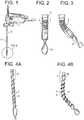
FIG. 1 shows a discectomy tool.FIGS. 2 and 3 show a distal portion of a discectomy tool.FIGS. 4A and 4B show transmission shafts.FIGS. 5A to 5F show approaches used by a discectomy tool in a disc space.FIGS. 6 to 8 show bent transmission shafts.FIGS. 9 to 11B show cannulae.FIG. 11C is a cross-sectional view of a cannula.FIG.11D is a side view of a cannula, revealing a first longitudinal face of the cannula.FIGS. 12 and 13 show cannulae with longitudinal steering elements.FIGS. 14 and 15 show cross-section of cannulae with embedded steering elements.FIGS. 16 and 17 show cannulae with longitudinal steering elements.FIGS. 18 and 19 show cannulae with dovetail notches for holding embedded steering elements.FIGS. 20 to 22 show cannulae in which the steering elements are metallic/polymeric tapered strips.FIG. 23 is a prior art Archimedes pump.FIG. 24 is a tool having integrated irrigation flow.FIG. 25 shows a helical spiral transmission shaft.FIG. 26 shows a helical spiral loosely connected to a transmission shaft.- Referring now to
FIGS. 1 to 4B , there is provided a discectomy tool comprising: - a) a
cannula 11 having anouter surface 13 having a longitudinal bore therein, a rigidproximal end portion 2 and a flexibledistal end portion 3, - b) a steering wire 4 longitudinally contacting the cannula and extending in the direction of the longitudinal bore,
- c) a flexible,
hollow transmission shaft 5 disposed in the cannula, the shaft having a throughbore, aproximal end portion 19, a flexible 6 distal end portion and anouter surface 21 having aflexible thread 7 extending therefrom, - d) an irrigation source fluidly connected to the throughbore,
- e) a
cutting tip 8 attached to the distal end portion of the transmission shaft, and - f) a drive/steer/irrigation handle 1.
- The invention is not limited to any particular approach trajectory of the working channel. For example, if a certain approach/trajectory offers an advantage in a given situation, the approach can be chosen accordingly. For example, and now referring to
FIGS. 5A to 5F , the surgeon may desire to use the tool in the following non-limiting approaches: - a) a flat angle extraforaminal approach (
FIG. 5A ), - b) a steep extraforaminal approach (
FIG. 5B ), - c) a translaminar approach (
FIG. 5C ), - d) a transformainal approach (
FIG. 5D ), - e) a far lateral approach (
FIG. 5E ), and - f) an anterior approach (
FIG. 5F ). - In order to increase the cleared volume of the disc, the tool can be serially inserted from multiple approaches, e.g. from two opposite sides of the disc. In a serial embodiment, one side of the disc is cleared and then the other side is cleared. In a simultaneous embodiment, the two sides of the disc are cleared simultaneously.
- The working channel can be straight or bent. Also, the cross sectional area of the working channel can vary (e.g., it can be a funnel-shaped working channel).
- In use, in some embodiments, the distal end portion of the tool can be swept side-to-side without longitudinal movement. In other embodiments, the distal end portion of the tool can be swept side-to-side with simultaneous unidirectional longitudinal movement. In other embodiments, the distal end portion of the tool can be swept side-to-side with simultaneous longitudinal back-and-forth movement.
- In some embodiments, the tool of the present invention is used to clear a disc. In others, it is used to clean disc endplates abutting the disc. In still others, it is used to both clear a disc and clear its associated endplates.
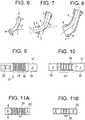
- Now referring to
FIGS. 6 to 8 , one goal of the present invention is to guide and steer a rotating, curved flexible transmission shaft that has to transmit an incoming torque Min (from the first right cylindrical portion A), in order to reach an outgoing torque Mout at the second right cylindrical portion B, where A and B are not always concentric, but oriented against each other over a certain (variable) angle α and have a flexible, curved portion in-between (seeFIG.6 ). In order to accomplish this goal, the steering cannula needs to be able to guide both straight transmission shaft portions A and B, but also to connect these guiding zones and actively change the angle between them (seeFIG.7 ) Merely providing the steering cannula with one or two joints between A and B would not be satisfactory because the joint geometry might interfere with the inner, rotating flexible shaft. Rather, because of the importance of optimizing the material transport and torque transmission, it is believed the inner rotating flexible shaft needs to have a smooth transition shape between portions A and B (i.e., no joints). Consistent with that desire is a belief that the steering cannula must also have a smooth transition shape in order to minimize interference and to maximize the guidance (as shown by the dotted line inFIG. 8 ). Merely providing a simple elastic tube as the flexible part (FP) of the cannula probably does not provide enough stability and at the same time enough flexibility. - Therefore, it is believed that the outer cannula should be stable against axial torsion, but bendable in one plane. It is further believed that the cannula geometry shown in
FIGS. 9 to 11B , consisting of alternating bullet-shaped cutouts, provides these desired qualities. Adequate detailed dimensioning of the cutout geometry can adjust and optimize the stiffness/stability, steering angle, steering radius of the cannula. - Referring now to
FIG. 9 to 11C , there is provided a discectomy tool comprising: - a) a
cannula 31 having aproximal end portion 33, adistal end portion 35, and anouter surface 37, the cannula having a first longitudinal face 38 and a second opposed longitudinal face, wherein the first longitudinal face has a plurality of alternating, opposedtransverse cutouts 39 therealong to form a substantially square wave 36 of the first longitudinal face, - b) a transmission shaft disposed in the cannula, the shaft having a proximal end portion and a distal end portion,
- c) a cutting tip attached to the distal end portion of the transmission shaft.
- Now referring to
FIG. 11D , preferably, thecutouts 101 have a tapereddistal end portion 41 so as to form a bullet shape. Also preferably, the width of themiddle portion 40 of the cutout is greater than the width of either theproximal end portion 42 or thedistal end portion 41. - The tool may further include bilateral pulling strips running alongside the cannula to steer the tool. In the intradiscal environment, the active steering force needs to be high (depending on the cutting ability and the resistance within the tissue).
- Now referring to
FIGS. 12 to 17 , in a preferred construction, pullingstrips 43 are arranged along both the left and the right side of the cannula, and are guided throughnotches 45. When pulled on the left string, the flexible steering cannula (SC) will bend to the left side, and vice versa (seeFIG.12 ). In some embodiments, the pullingstrip 43 can be disposed on the inside of the steering cannula (see FIG.fig.13 ). In some constructions, the pullingstrips 43 are integrated into thecannula wall 47 via notches. The cannula wall thickness has to be as small as possible, in order to have as much cross sectional area as possible in the inner lumen (FIGS. 16 and 17 ). The "notch" embodiments allow the cannula inner lumen to be as large as possible to allow the rotating member to contain irrigation, torque transmission and the transport auger) - In other constructions, the steering is accomplished by using a pushing force. This preferably occurs without uncontrolled deformation of the strip. The ability of the steering to accomplish these goals is due to the dovetail feature.
- Referring now to
FIGS. 12 to 19 , there is provided a discectomy tool comprising - a) a
cannula 31 having aproximal end portion 33, adistal end portion 35, and anouter surface 37, - b) a transmission shaft disposed in the cannula, the shaft having a proximal end portion and a distal end portion,
- c) a cutting tip attached to the distal end portion of the transmission shaft,
- d) first and
second steering elements 43 bilaterally and longitudinally disposed on the outer surface of the cannula. - In some constructions,
longitudinal notches 45 are provided on the inner steering cannula wall 49 (seeFIG. 14 ). This construction, however, may be a production challenge, since EDM or profile extrusion are expensive. To have the notch on theoutside surface 37 of the cannula (seeFIG. 15 ) would offer an easier manufacturing. Moreover, its lever ratio would be more beneficial (more side bending force at the same pulling strength). - Referring now to
FIG. 15 , there is provided a discectomy tool comprising: - a) a cannula having a proximal end, a distal end, and an outer surface having a first longitudinal recess (notch) therein,
- b) a transmission shaft disposed in the cannula, the shaft having a proximal end portion and a distal end portion,
- c) a cutting tip attached to the distal end portion of the transmission shaft,
- d) a first steering element disposed in the first longitudinal recess of the outer surface.
- Without wishing to be tied to a theory, it is believed that simply making the notch 45 a rectangular shape would easily allow the pulling strings to fall out. Therefore, one solution regarding steering force and manufacturing possibilities is a dovetail-like profile notch that is easily retains the like-shaped steering strip. More generally, the dovetail is one example in which the first longitudinal recess has a transverse opening at the outer surface and the steering element has a maximum transverse cross-section, wherein the maximum cross-section is greater than the opening of the recess at the outer surface, thereby preventing expulsion of the steering element from the recess.
- Now referring to
FIGS. 20 to 22 , in some constructions, the steering elements are flat metallic/polymeric tapered strips 51. They have the mechanical property of being very flexible in up- down bending, but quite stable in lateral bending. This lateral bending stability of the steering strips is essential to increase the torsional stability of the outer cannula assembly. A further advantage of flat steering strips is that the wall thickness of the outer cannula can be very small. Such steering strips have the big advantage that simultaneous pulling on one string and pushing on the other string increases the steering force and keeps the length of the neutral axis of the steering cannula constant in length if it is steered. In contrast, in many other conventional tools, steering is limited to only pulling and uses only a single pulling strip. Thus, in the present invention, there is much more defined motion, which is important in navigation. - A common challenge in discectomies is to not only to cut and detach disc material from the disc proper, but also to transport the excised disc material automatically out of the body. It is important to prevent the tissue from clogging the tool. Auger systems (modelled after the Archimedes pump shown in
FIG. 23 ) have been proposed to achieve these goals. However, wishing to be tied to a theory, it is believed that a simple Archimedes pump itself might not be sufficient to guarantee a proper transport of the cut disc material fragment, as the disc material might get dry and stick to the auger walls, which finally leads to a clogging of several fragments and a transport interruption. - In order to prevent this clogging, and now referring to
FIG. 24 , some constructions of tool integrate irrigation flow from an irrigation flow means (not shown) into the tool. The inflow can be performed either between the outer cannula of the disc removal device and the working channel, or through a central lumen inside the auger. With irrigation through an inner lumen, the exit point of the inflow can be located close to the cutting blade or from within the cutting blade. This allows having a permanent inflow over the blade geometries during the cutting, and helps to keep the blade clean. If the blade cannot be kept clean, especially sharp edges can get covered with disc tissue and decrease the cutting ability of the blade. - It is believed that a smooth continuous transport geometry without sudden transitions is desirable to reach a reliable transport of the cut disc material fragments. However, in use, in the steerable area of the transmission shaft, the bending radius can be below 15 mm. Thus, it is desired to provide a tool that provides small bending radii, smooth auger geometry transition and adequate torque transmission. One solution is to provide a flexible torque transmission shaft overlaid by, but not directly connected to, a flexible auger element. It is believed that if directly connected at the flexible/steerable area, the construct would lose a certain amount of its flexibility, so transitional movements between the flexible torque transmission shaft and the flexible auger do have to be possible. The "loose" auger avoids this problem.
- However, the flexible auger is preferably connected with the cutting blade on its distal end, and with the straight/stiff threaded shaft on its proximal end, and allows very smooth geometrical transitions between these different elements in order to prevent obstacles for a reduced resistance tissue/material transport from the cutting blade along to the auger flanks.
- The flexible auger portion can comprise either:
- a) polymeric or metal spiral alone, in case of very low torque transmission: (see
FIG. 25 ), - b) a polymeric spiral connected to a tube which is connected to the inner shaft at an extension, but not along the flexible/steering zone (decreases bending stiffness), in case of higher torque transmission (see
FIG. 26 )). - Now referring to
FIG. 25 , there is provided a discectomy tool comprising: - a) a cannula having an outer surface having a longitudinal bore therein, a proximal end and a distal end,
- b) a transmission shaft having a proximal end portion and a distal end portion,
- c) a rotatable cutting tip having a proximal end portion, and
- d) a flexible
helical auger 101 having aproximal end portion 103 and adistal end portion 105, wherein the proximal end portion of the auger is connected to the transmission shaft, and wherein the distal end portion of the auger is connected to the proximal end portion of the cutting tip, - In some embodiments, the auger can be manufactured by attaching a flexible (e.g., PEEK) auger to a metal (preferably threaded) transmission shaft.
- Referring now to
FIG. 26 , there is provided a discectomy tool comprising: - a) a cannula having an outer surface having a longitudinal bore therein, a proximal end and a distal end,
- b) a transmission shaft having a proximal end portion and a distal end portion,
- c) a rotatable cutting tip attached to the distal end portion of the transmission shaft, and
- d) a flexible helical auger having a proximal end portion, and intermediate portion and a distal end portion, wherein the intermediate portion is loosely wrapped around the flexible torque transmission shaft, wherein the proximal end portion of the auger is connected to the transmission shaft, and wherein the distal end portion of the auger is connected to the proximal end portion of the cutting tip,
- The loose auger in this flexible torque transmission shaft can be provided in a number of ways, such as the following non-limiting examples:
- a) narrow spring,
- b) solid tube shaft of flexible material,
- c) solid metal shaft with specific cutouts to become flexible in bending etc.)
- For the outflow, a suction device can be connected with the auger/transport lumen so that a continuous liquid flow is helping to transport the cut disc material fragments.
- In some constructions, the tool has a safety housing to prevent cutting of anatomic elements outside of the intervertebral disc, as, for example, the endplates of the adjacent vertebrae. With a safety housing, the blade is only able to cut to one side, and not to progress in depth. After an initial cylindrical hole is drilled (with a standard drill), the tip of the disc removal device can be inserted until it touches the ground of the hole. After this, the tip can only be steered to one direction. This means that if the depth of the initial drilled hole determines the reachable area of the cutting tip.
- The invention also provides discectomy tools having features which are specified in the following numbered clauses:
- 1. A discectomy tool comprising:
- a) a cannula having an outer surface having a longitudinal bore therein, a proximal end portion and a distal end portion,
- b) a steering wire longitudinally contacting the cannula and extending in the direction of the longitudinal bore,
- c) a flexible, hollow transmission shaft disposed in the cannula, the shaft having a throughbore, a proximal end portion, a distal end portion and an outer surface having a thread extending therefrom,
- d) an irrigation source fluidly connected to the throughbore,
- e) a cutting tip attached to the distal end portion of the transmission shaft.
- 2. The tool of clause 1 wherein the cannula has longitudinally repeating cutouts to produce increased flexibility.
- 3. The tool of
clause 2 wherein the repeating cutouts form a square wave in a face of the cannula. - 4. The tool of clause 1 wherein the shaft and cutting tip extend through the distal end of the cannula.
- 5. A discectomy tool comprising:
- a) a cannula having an outer surface having a longitudinal bore therein, a proximal end and a distal end,
- b) a transmission shaft having a proximal end portion and a distal end portion,
- c) a rotatable cutting tip attached to the distal end portion of the transmission shaft, and
- d) a flexible helical auger having a proximal end portion, and intermediate portion and a distal end portion, wherein the intermediate portion is loosely wrapped around the flexible torque transmission shaft,
- 6. The tool of
clause 5 wherein the distal end portion of the auger is rigidly attached to the distal end portion of the cutting shaft, and wherein the proximal end portion of the auger is rigidly attached to the proximal end portion of the cutting shaft. - 7. The tool of
clause 5 where the intermediate portion of the auger is loosely wrapped around the transmission shaft, the proximal end portion of the auger is connected to the transmission shaft, and the distal end portion of the auger is connected to the proximal end portion of the cutting tip. - 8. A discectomy tool comprising:
- a) a cannula having an outer surface having a longitudinal bore therein, a proximal end and a distal end,
- b) a transmission shaft having a proximal end portion and a distal end portion,
- c) a rotatable cutting tip attached to the distal end portion of the transmission shaft, and
- d) a flexible helical auger having a proximal end portion, a hollow intermediate portion and a distal end portion, wherein the proximal end portion of the auger is connected to the torque transmission shaft and the distal end portion of the auger is connected to the cutting tip,
- 9. A discectomy tool comprising:
- a) a cannula having a proximal end, a distal end, and an outer surface having a first longitudinal recess therein,
- b) a transmission shaft disposed in the cannula, the shaft having a proximal end portion and a distal end portion,
- c) a cutting tip attached to the distal end portion of the transmission shaft,
- d) a first steering element disposed in the first longitudinal recess of the outer surface.
- 10. The tool of clause 9 wherein the first longitudinal recess has an opening at the outer surface and the steering element has a maximum cross-section, wherein the maximum cross-section is greater than the opening of the recess at the outer surface.
- 11. The tool of clause 9 wherein the cannula has a second longitudinal recess in its outer surface, the tool further comprising a second steering element disposed in the second longitudinal recess of the outer surface.
- 12. The tool of clause 9 wherein the second longitudinal recess and the second steering element have matching dovetail cross-sections.
- 13. The tool of clause 9 wherein the steering elements is a flat metallic or polymeric strip.
- 14. The tool of clause 9 wherein the steering elements is a flat metallic or polymeric tapered strip.
- 15. A discectomy tool comprising:
- a) a cannula having a proximal end, a distal end, and an outer surface,
- b) a transmission shaft disposed in the cannula, the shaft having a proximal end portion and a distal end portion,
- c) a cutting tip attached to the distal end portion of the transmission shaft,
- d) first and second steering elements bilaterally and longitudinally disposed on the outer surface of the cannula.
- 16. A discectomy tool comprising:
- a) a cannula having a proximal end portion, a distal end portion, and an outer surface, the cannula having a first longitudinal face and a second opposed longitudinal face, wherein the first longitudinal face has a plurality of alternating, opposed transverse cutouts therealong to form a substantially square wave of the first longitudinal face,
- b) a transmission shaft disposed in the cannula, the shaft having a proximal end portion and a distal end portion,
- c) a cutting tip attached to the distal end portion of the transmission shaft.
- 17. The tool of clause 16 further comprising a first steering wire contacting the outer surface of the cannula substantially along the single bending plane.
- 18. The tool of clause 17 further comprising a second steering wire contacting the outer surface of the cannula substantially along the single bending plane.
- 19. The tool of clause 18 wherein the cutouts have a tapered distal end portion so as to form a bullet shape.
- 20. The tool of clause 18 wherein at least one cutout has a proximal end portion, a middle portion and a distal end portion, each portion having a width, and wherein the width of the middle portion of the cutout is greater than the width of either the proximal end portion or the distal end portion.
- 21. A discectomy tool comprising:
- a) a cannula having an outer surface having a longitudinal bore therein, a proximal end and a distal end,
- b) a transmission shaft having a proximal end portion and a distal end portion,
- c) a rotatable cutting tip having a proximal end portion, and
- d) a flexible helical auger having a proximal end portion, and intermediate portion and a distal end portion, wherein the proximal end portion of the auger is connected to the distal end portion of the transmission shaft, and wherein the distal end portion of the auger is connected to the proximal end portion of the cutting tip,
wherein the cutting tip extends out the bore at the distal end of the cannula.
wherein the cutting tip extends out the bore at the distal end of the cannula.
Claims (14)
- A discectomy tool comprising:a) a cannula (11,31) having an outer surface (13, 37) having a longitudinal bore therein, a proximal end (2, 33) and a distal end (3, 35),b) a torque transmission shaft (5) having a proximal end portion (19) and a flexible distal end portion (6), wherein the transmission shaft is adapted to rotate within the longitudinal bore of the cannula,c) a rotatable cutting tip (8) attached to the distal end portion of the transmission shaft, and wherein the cutting tip extends out the bore at the distal end of the cannula, andd) a flexible helical auger (101) having a proximal end portion (103) connected to the proximal end portion of the transmission shaft, an intermediate portion and a distal end portion (105), wherein the intermediate portion of the flexible helical auger is loosely wrapped around the flexible distal end portion of the transmission shaft, wherein the flexible helical auger is a solid tube shaft of flexible material, and wherein the auger is adapted to rotate within the longitudinal bore of the cannula.
- The tool of claim 1 wherein the distal end portion of the auger is connected to a proximal end portion of the cutting tip.
- The tool of claim 1, wherein the transmission shaft disposed in the cannula is hollow having a throughbore, and further comprising:a steering wire (4) longitudinally contacting the cannula and extending in the direction of the longitudinal bore of the cannula, andan irrigation source fluidly connected to the throughbore of the transmission shaft.
- The tool of claim 1 wherein the cannula has longitudinally repeating cutouts (39, 101) to produce increased flexibility, wherein the repeating cutouts optionally form a square wave (36) in a face of the cannula.
- The tool of claim 1, further comprising:a first steering element (43) disposed in a first longitudinal recess of the outer surface.
- The tool of claim 5 wherein the first longitudinal recess has an opening at the outer surface and the first steering element has a maximum cross-section, wherein the maximum cross-section is greater than the opening of the recess at the outer surface.
- The tool of claim 5 wherein the outer surface of the cannula has a second longitudinal recess, the tool further comprising a second steering element (43) disposed in the second longitudinal recess of the outer surface.
- The tool of claim 5 wherein the first longitudinal recess of the outer surface of the cannula and the first steering element have matching dovetail cross-sections.
- The tool of claim 5 wherein the first steering element is a flat metallic or polymeric tapered strip (51).
- The tool of claim 1, further comprising:first and second steering elements (43) bilaterally and longitudinally disposed on the outer surface of the cannula.
- The tool of claim 1, wherein:the cannula has a first longitudinal face and a second opposed longitudinal face, wherein the first longitudinal face has a plurality of alternating, opposed transverse cutouts therealong to form a substantially square wave of the first longitudinal face.
- The tool of claim 11 further comprising a first steering wire contacting the outer surface of the cannula substantially along a single bending plane.
- The tool of claim 11, wherein the cutouts have a tapered distal end portion (41) so as to form a bullet shape.
- The tool of claim 11, wherein at least one cutout has a proximal end portion (42), a middle portion (40) and a distal end portion (41), each portion having a width, and wherein the width of the middle portion of the cutout is greater than the width of either the proximal end portion or the distal end portion.
Applications Claiming Priority (3)
| Application Number | Priority Date | Filing Date | Title |
|---|---|---|---|
| US14/674,310US10786264B2 (en) | 2015-03-31 | 2015-03-31 | Percutaneous disc clearing device |
| PCT/EP2016/057045WO2016156482A1 (en) | 2015-03-31 | 2016-03-31 | Percutaneous disc clearing device |
| EP16712369.4AEP3277202B1 (en) | 2015-03-31 | 2016-03-31 | Percutaneous disc clearing device |
Related Parent Applications (1)
| Application Number | Title | Priority Date | Filing Date |
|---|---|---|---|
| EP16712369.4ADivisionEP3277202B1 (en) | 2015-03-31 | 2016-03-31 | Percutaneous disc clearing device |
Publications (2)
| Publication Number | Publication Date |
|---|---|
| EP3494905A1true EP3494905A1 (en) | 2019-06-12 |
| EP3494905B1 EP3494905B1 (en) | 2022-06-15 |
Family
ID=55640757
Family Applications (2)
| Application Number | Title | Priority Date | Filing Date |
|---|---|---|---|
| EP19152080.8AActiveEP3494905B1 (en) | 2015-03-31 | 2016-03-31 | Percutaneous disc clearing device |
| EP16712369.4AActiveEP3277202B1 (en) | 2015-03-31 | 2016-03-31 | Percutaneous disc clearing device |
Family Applications After (1)
| Application Number | Title | Priority Date | Filing Date |
|---|---|---|---|
| EP16712369.4AActiveEP3277202B1 (en) | 2015-03-31 | 2016-03-31 | Percutaneous disc clearing device |
Country Status (6)
| Country | Link |
|---|---|
| US (4) | US10786264B2 (en) |
| EP (2) | EP3494905B1 (en) |
| JP (1) | JP6830901B2 (en) |
| CN (1) | CN107708584B (en) |
| AU (1) | AU2016239954B2 (en) |
| WO (1) | WO2016156482A1 (en) |
Families Citing this family (41)
| Publication number | Priority date | Publication date | Assignee | Title |
|---|---|---|---|---|
| DE10154163A1 (en) | 2001-11-03 | 2003-05-22 | Advanced Med Tech | Device for straightening and stabilizing the spine |
| US8979931B2 (en) | 2006-12-08 | 2015-03-17 | DePuy Synthes Products, LLC | Nucleus replacement device and method |
| US20090088789A1 (en) | 2007-09-28 | 2009-04-02 | O'neil Michael J | Balloon With Shape Control For Spinal Procedures |
| BRPI0818608A2 (en) | 2007-10-05 | 2015-04-22 | Synthes Gmbh | Sequential directional dilatation system for dilating from a nerve of a patient's anatomy, and method for forming an access opening through a psoas muscle to a patient's spine using a dilatation system |
| US9420971B2 (en) | 2009-10-24 | 2016-08-23 | Carrot Sense, Inc. | Extracorporeal devices and methods for facilitating cessation of undesired behaviors |
| US9622779B2 (en) | 2011-10-27 | 2017-04-18 | DePuy Synthes Products, Inc. | Method and devices for a sub-splenius / supra-levator scapulae surgical access technique |
| US9808232B2 (en) | 2011-11-01 | 2017-11-07 | DePuy Synthes Products, Inc. | Dilation system |
| US9265490B2 (en) | 2012-04-16 | 2016-02-23 | DePuy Synthes Products, Inc. | Detachable dilator blade |
| US9480855B2 (en) | 2012-09-26 | 2016-11-01 | DePuy Synthes Products, Inc. | NIR/red light for lateral neuroprotection |
| US9980737B2 (en) | 2014-08-04 | 2018-05-29 | Medos International Sarl | Flexible transport auger |
| US10111712B2 (en) | 2014-09-09 | 2018-10-30 | Medos International Sarl | Proximal-end securement of a minimally invasive working channel |
| US10264959B2 (en) | 2014-09-09 | 2019-04-23 | Medos International Sarl | Proximal-end securement of a minimally invasive working channel |
| US9924979B2 (en) | 2014-09-09 | 2018-03-27 | Medos International Sarl | Proximal-end securement of a minimally invasive working channel |
| US10786264B2 (en) | 2015-03-31 | 2020-09-29 | Medos International Sarl | Percutaneous disc clearing device |
| JP6773762B2 (en) | 2015-04-07 | 2020-10-21 | キャロット,インコーポレイテッド | Systems and methods for quantifying and predicting smoking behavior |
| US10206572B1 (en) | 2017-10-10 | 2019-02-19 | Carrot, Inc. | Systems and methods for quantification of, and prediction of smoking behavior |
| CN113143355A (en) | 2015-09-04 | 2021-07-23 | 美多斯国际有限公司 | Multi-shield spinal access system |
| US12150636B2 (en) | 2015-09-04 | 2024-11-26 | Medos International Sárl | Surgical instrument connectors and related methods |
| US11744447B2 (en) | 2015-09-04 | 2023-09-05 | Medos International | Surgical visualization systems and related methods |
| US11672562B2 (en) | 2015-09-04 | 2023-06-13 | Medos International Sarl | Multi-shield spinal access system |
| US10987129B2 (en) | 2015-09-04 | 2021-04-27 | Medos International Sarl | Multi-shield spinal access system |
| US11439380B2 (en) | 2015-09-04 | 2022-09-13 | Medos International Sarl | Surgical instrument connectors and related methods |
| US10321919B2 (en)* | 2015-10-07 | 2019-06-18 | Tenjin LLC | Powered endoscope drilling device |
| US10299838B2 (en) | 2016-02-05 | 2019-05-28 | Medos International Sarl | Method and instruments for interbody fusion and posterior fixation through a single incision |
| US10653431B2 (en)* | 2016-06-14 | 2020-05-19 | Medos International Sarl | Drill assemblies and methods for drilling into bone |
| USD878586S1 (en) | 2017-09-07 | 2020-03-17 | G21 S.R.L. | Biomedical device |
| USD879293S1 (en) | 2017-09-07 | 2020-03-24 | G21 S.R.L. | Biomedical device |
| US10987175B2 (en) | 2017-12-06 | 2021-04-27 | Medtech S.A. | Robotic shoulder repair and reconstruction |
| US10687792B2 (en)* | 2018-03-12 | 2020-06-23 | Zimmer Biomet CMF and Thoracic, LLC | End effector coupler for surgical arm |
| US11000295B2 (en)* | 2018-09-27 | 2021-05-11 | Acumed Llc | Bone harvesting system |
| US11013530B2 (en) | 2019-03-08 | 2021-05-25 | Medos International Sarl | Surface features for device retention |
| US11241252B2 (en) | 2019-03-22 | 2022-02-08 | Medos International Sarl | Skin foundation access portal |
| US11129727B2 (en) | 2019-03-29 | 2021-09-28 | Medos International Sari | Inflatable non-distracting intervertebral implants and related methods |
| US11813026B2 (en) | 2019-04-05 | 2023-11-14 | Medos International Sarl | Systems, devices, and methods for providing surgical trajectory guidance |
| JP7250639B2 (en)* | 2019-07-31 | 2023-04-03 | 真 小林 | High-frequency knife device for endoscope |
| MX2022008186A (en) | 2019-12-30 | 2022-09-23 | Cilag Gmbh Int | Systems and methods for assisting individuals in a behavioral-change program. |
| JP2022090253A (en)* | 2020-12-07 | 2022-06-17 | テルモ株式会社 | Lymphangiogenesis induction device |
| US11771517B2 (en) | 2021-03-12 | 2023-10-03 | Medos International Sarl | Camera position indication systems and methods |
| DE102021115486A1 (en)* | 2021-06-15 | 2022-12-15 | Joimax Gmbh | Medical instrument, medical instrument set, medical device and medical procedure |
| US11534309B1 (en) | 2021-07-20 | 2022-12-27 | Globus Medical Inc. | Interlaminar lumbar interbody fusion implants, intradiscal implants, instruments, and methods |
| US12274627B2 (en) | 2021-07-20 | 2025-04-15 | Globus Medical, Inc. | Interlaminar lumbar interbody fusion system and associated robotic systems |
Citations (35)
| Publication number | Priority date | Publication date | Assignee | Title |
|---|---|---|---|---|
| US4646738A (en) | 1985-12-05 | 1987-03-03 | Concept, Inc. | Rotary surgical tool |
| US4678459A (en) | 1984-07-23 | 1987-07-07 | E-Z-Em, Inc. | Irrigating, cutting and aspirating system for percutaneous surgery |
| US4863430A (en) | 1987-08-26 | 1989-09-05 | Surgical Dynamics, Inc. | Introduction set with flexible trocar with curved cannula |
| US5195541A (en) | 1991-10-18 | 1993-03-23 | Obenchain Theodore G | Method of performing laparoscopic lumbar discectomy |
| US5285795A (en) | 1991-09-12 | 1994-02-15 | Surgical Dynamics, Inc. | Percutaneous discectomy system having a bendable discectomy probe and a steerable cannula |
| US5529580A (en) | 1987-10-30 | 1996-06-25 | Olympus Optical Co., Ltd. | Surgical resecting tool |
| US5540706A (en) | 1993-01-25 | 1996-07-30 | Aust; Gilbert M. | Surgical instrument |
| US5591187A (en) | 1995-07-14 | 1997-01-07 | Dekel; Moshe | Laparoscopic tissue retrieval device and method |
| US6053907A (en) | 1998-08-13 | 2000-04-25 | Endius Incorporated | Surgical instruments with flexible drive shaft |
| US20020138020A1 (en) | 2001-03-23 | 2002-09-26 | Devonrex, Inc. | Micro-invasive breast biopsy device |
| US6468289B1 (en) | 1990-06-28 | 2002-10-22 | Peter M. Bonutti | Apparatus and method for tissue removal |
| US20030171744A1 (en) | 2002-03-05 | 2003-09-11 | Baylis Medical Co. Inc. | Intradiscal lesioning device |
| US20030191474A1 (en) | 2000-02-16 | 2003-10-09 | Cragg Andrew H. | Apparatus for performing a discectomy through a trans-sacral axial bore within the vertebrae of the spine |
| US20040127992A1 (en) | 2002-12-31 | 2004-07-01 | Serhan Hassan A. | Annular nucleus pulposus replacement |
| US20050090848A1 (en) | 2003-10-22 | 2005-04-28 | Adams Kenneth M. | Angled tissue cutting instruments and method of fabricating angled tissue cutting instruments having flexible inner tubular members of tube and sleeve construction |
| US20060206118A1 (en) | 2005-03-11 | 2006-09-14 | Kim Daniel H | Percutaneous endoscopic access tools for the spinal epidural space and related methods of treatment |
| US20070055259A1 (en) | 2005-08-17 | 2007-03-08 | Norton Britt K | Apparatus and methods for removal of intervertebral disc tissues |
| US20070149975A1 (en) | 2005-11-29 | 2007-06-28 | Oliver Dana A | Method and apparatus for removing material from an intervertebral disc space, such as in performing a nucleotomy |
| US20080004646A1 (en)* | 2006-06-30 | 2008-01-03 | Atheromed, Inc. | Atherectomy devices and methods |
| US20080015621A1 (en) | 1997-09-04 | 2008-01-17 | Smith & Nephew, Inc. | Surgical endoscopic cutting device and method for its use |
| WO2009033207A1 (en) | 2007-09-12 | 2009-03-19 | Columna Pty Ltd | Equipment for, and a method of, removing tissue from a site in a patient's body |
| US20100076476A1 (en) | 2008-07-25 | 2010-03-25 | To John T | Systems and methods for cable-based tissue removal |
| US20100151161A1 (en) | 2005-10-05 | 2010-06-17 | Orlando Da Rolo | Flexible hollow shaft |
| US20100161060A1 (en) | 2008-12-23 | 2010-06-24 | Benvenue Medical, Inc. | Tissue Removal Tools And Methods Of Use |
| US20110054507A1 (en) | 2009-04-17 | 2011-03-03 | David Batten | Devices and methods for arched roof cutters |
| US20110087257A1 (en)* | 2009-04-02 | 2011-04-14 | Spine View, Inc. | Minimally invasive discectomy |
| US8118813B2 (en)* | 2006-11-29 | 2012-02-21 | Mi4Spine, Llc | Bone graft delivery system for a vertebral interbody device |
| US20120209273A1 (en) | 2010-11-15 | 2012-08-16 | Zaretzka Gary D | Tissue removal system with retention mechanism |
| US20120221007A1 (en) | 2010-12-20 | 2012-08-30 | David Batten | Articulating tissue removal systems and methods |
| US20130103067A1 (en) | 2011-07-28 | 2013-04-25 | Myra I. L. Fabro | Discectomy devices and related methods |
| US8585726B2 (en) | 2012-01-31 | 2013-11-19 | Globus Medical, Inc. | Surgical disc removal tool |
| US20140180321A1 (en)* | 2012-12-20 | 2014-06-26 | Spine View, Inc. | Discectomy devices and methods |
| US8784421B2 (en) | 2004-03-03 | 2014-07-22 | Boston Scientific Scimed, Inc. | Apparatus and methods for removing vertebral bone and disc tissue |
| US20140276840A1 (en) | 2013-03-15 | 2014-09-18 | DePuy Synthes Products, LLC | Tools and methods for tissue removal |
| WO2015138432A1 (en)* | 2014-03-11 | 2015-09-17 | Stryker European Holdings I, Llc | Intramedullary autograft harvester |
Family Cites Families (251)
| Publication number | Priority date | Publication date | Assignee | Title |
|---|---|---|---|---|
| US4573448A (en) | 1983-10-05 | 1986-03-04 | Pilling Co. | Method for decompressing herniated intervertebral discs |
| US4888146A (en) | 1988-05-19 | 1989-12-19 | Dandeneau James V | Method and apparatus of forming extruded article |
| US5080662A (en) | 1989-11-27 | 1992-01-14 | Paul Kamaljit S | Spinal stereotaxic device and method |
| IT1249714B (en) | 1991-10-11 | 1995-03-09 | Mauro Caponi | DOUBLE CANNAL SURGICAL INSTRUMENT. |
| US5395317A (en) | 1991-10-30 | 1995-03-07 | Smith & Nephew Dyonics, Inc. | Unilateral biportal percutaneous surgical procedure |
| US5683082A (en)* | 1992-08-04 | 1997-11-04 | Kabushiki Kaisha Ace Denken | Gaming system controlling termination of playing and degree of playing difficulty |
| US5735792A (en) | 1992-11-25 | 1998-04-07 | Clarus Medical Systems, Inc. | Surgical instrument including viewing optics and an atraumatic probe |
| US5439464A (en) | 1993-03-09 | 1995-08-08 | Shapiro Partners Limited | Method and instruments for performing arthroscopic spinal surgery |
| US5387220A (en) | 1993-06-15 | 1995-02-07 | Pisharodi; Maohaven | Stereotactic frame and localization method |
| US5513827A (en) | 1993-07-26 | 1996-05-07 | Karlin Technology, Inc. | Gooseneck surgical instrument holder |
| DE9415039U1 (en) | 1994-09-16 | 1994-11-03 | Kernforschungszentrum Karlsruhe Gmbh, 76133 Karlsruhe | Device for guiding surgical instruments |
| US5562695A (en) | 1995-01-10 | 1996-10-08 | Obenchain; Theodore G. | Nerve deflecting conduit needle and method |
| US5569290A (en) | 1995-01-30 | 1996-10-29 | Paul C. McAfee | Method of and apparatus for laparoscopic or endoscopic spinal surgery using an unsealed anteriorly inserted transparent trochar |
| WO1996029014A1 (en) | 1995-03-22 | 1996-09-26 | Evi Corporation | Intra-artery obstruction clearing apparatus and methods |
| DE19520277C1 (en) | 1995-06-02 | 1996-11-21 | Winter & Ibe Olympus | Endoscopic instrument with flushing passage |
| JPH10505286A (en) | 1995-06-20 | 1998-05-26 | シン ング、ワン | Articulated arm for medical procedures |
| US5733242A (en) | 1996-02-07 | 1998-03-31 | Rayburn; Robert L. | Intubation system having an axially moveable memory cylinder |
| DE19780707C2 (en) | 1996-03-22 | 2002-09-12 | Sdgi Holdings Inc | Percutaneous surgery device |
| US5792044A (en) | 1996-03-22 | 1998-08-11 | Danek Medical, Inc. | Devices and methods for percutaneous surgery |
| JP3819962B2 (en) | 1996-04-01 | 2006-09-13 | ペンタックス株式会社 | Interbody fusion implant guide device |
| DE69735146T2 (en) | 1996-05-09 | 2006-09-28 | Olympus Corporation | Surgical tool for holding a cavity |
| US7104986B2 (en) | 1996-07-16 | 2006-09-12 | Arthrocare Corporation | Intervertebral disc replacement method |
| US6322498B1 (en) | 1996-10-04 | 2001-11-27 | University Of Florida | Imaging scope |
| US5894369A (en) | 1996-11-15 | 1999-04-13 | Fuji Photo Optical Co., Ltd. | Lens device with anti-fogging |
| US6033105A (en) | 1996-11-15 | 2000-03-07 | Barker; Donald | Integrated bone cement mixing and dispensing system |
| US5899425A (en) | 1997-05-02 | 1999-05-04 | Medtronic, Inc. | Adjustable supporting bracket having plural ball and socket joints |
| US5921956A (en) | 1997-09-24 | 1999-07-13 | Smith & Nephew, Inc. | Surgical instrument |
| AUPP294698A0 (en) | 1998-04-15 | 1998-05-07 | Gray, Bruce | Removable ball joint |
| US6110182A (en) | 1998-06-22 | 2000-08-29 | Ohio Medical Instruments Company, Inc. | Target socket |
| US6063021A (en) | 1998-07-31 | 2000-05-16 | Pilling Weck Incorporated | Stabilizer for surgery |
| US6296644B1 (en) | 1998-08-26 | 2001-10-02 | Jean Saurat | Spinal instrumentation system with articulated modules |
| US6286179B1 (en) | 1998-10-19 | 2001-09-11 | Donny M. Byrne | Apparatus and method for removing debris from the lens-cleaning nozzle of an endoscope |
| US6626830B1 (en) | 1999-05-04 | 2003-09-30 | Cardiothoracic Systems, Inc. | Methods and devices for improved tissue stabilization |
| US7637905B2 (en) | 2003-01-15 | 2009-12-29 | Usgi Medical, Inc. | Endoluminal tool deployment system |
| US6283966B1 (en) | 1999-07-07 | 2001-09-04 | Sulzer Spine-Tech Inc. | Spinal surgery tools and positioning method |
| US6200322B1 (en) | 1999-08-13 | 2001-03-13 | Sdgi Holdings, Inc. | Minimal exposure posterior spinal interbody instrumentation and technique |
| DE29916026U1 (en) | 1999-09-11 | 1999-11-18 | Aesculap AG & Co. KG, 78532 Tuttlingen | Holding device for a surgical instrument |
| US6575899B1 (en) | 1999-10-20 | 2003-06-10 | Sdgi Holdings, Inc. | Methods and instruments for endoscopic interbody surgical techniques |
| US6447446B1 (en) | 1999-11-02 | 2002-09-10 | Medtronic Xomed, Inc. | Method and apparatus for cleaning an endoscope lens |
| US6354992B1 (en) | 1999-11-08 | 2002-03-12 | Daniel T. Kato | Automated laparoscopic lens cleaner |
| US6648915B2 (en) | 1999-12-23 | 2003-11-18 | John A. Sazy | Intervertebral cage and method of use |
| US6684886B1 (en) | 2000-01-21 | 2004-02-03 | Prospine, Inc. | Intervertebral disc repair methods and apparatus |
| NL1014255C2 (en) | 2000-02-01 | 2001-08-02 | Univ Medisch Centrum Utrecht | Support arm for operating purposes. |
| US6808505B2 (en) | 2000-02-01 | 2004-10-26 | Kadan Jeffrey S | Diagnostic needle arthroscopy and lavage system |
| US6575979B1 (en) | 2000-02-16 | 2003-06-10 | Axiamed, Inc. | Method and apparatus for providing posterior or anterior trans-sacral access to spinal vertebrae |
| US20020022762A1 (en) | 2000-02-18 | 2002-02-21 | Richard Beane | Devices and methods for warming and cleaning lenses of optical surgical instruments |
| US6383191B1 (en) | 2000-03-15 | 2002-05-07 | Sdgi Holdings, Inc. | Laparoscopic instrument sleeve |
| DE10019321C2 (en) | 2000-04-19 | 2002-03-14 | Storz Karl Gmbh & Co Kg | Flexible tensioning device, in particular for medical purposes |
| DE10024728A1 (en) | 2000-05-19 | 2001-11-22 | Ami Gmbh | Unit cleaning endoscopic instrument window in-situ during intervention, comprises detachable end casing with insufflation- and flushing channels |
| AU2001270180A1 (en) | 2000-06-30 | 2002-01-14 | Abbott Laboratories | Surgical support clamp |
| US6579281B2 (en) | 2000-10-11 | 2003-06-17 | Popcab, Llc | Instrument stabilizer for through-a-port surgery |
| US6558407B1 (en) | 2000-10-24 | 2003-05-06 | Tyco Healthcare Group Lp | Breast stabilizer with instrument guide |
| US6676597B2 (en) | 2001-01-13 | 2004-01-13 | Medtronic, Inc. | Method and device for organ positioning |
| US7144393B2 (en) | 2001-05-15 | 2006-12-05 | Dipoto Gene P | Structure for receiving surgical instruments |
| IL143682A0 (en) | 2001-06-11 | 2002-04-21 | Shalman Michael | Endoscope with cleaning optics |
| US7137949B2 (en) | 2001-07-13 | 2006-11-21 | United States Surgical Corporation | Surgical instrument |
| US6887198B2 (en) | 2001-10-05 | 2005-05-03 | Burns P. Phillips | Gooseneck surgical retractor positioner and method of its use |
| US20030083555A1 (en) | 2001-10-29 | 2003-05-01 | Scott Hunt | Segmented arm support system and method for stabilizing tissue |
| US7182731B2 (en) | 2002-01-23 | 2007-02-27 | Genesee Biomedical, Inc. | Support arm for cardiac surgery |
| US8043287B2 (en) | 2002-03-05 | 2011-10-25 | Kimberly-Clark Inc. | Method of treating biological tissue |
| US6758809B2 (en) | 2002-06-06 | 2004-07-06 | Medtronic, Inc. | Surgical tool for engagement of body tissue |
| US7074226B2 (en) | 2002-09-19 | 2006-07-11 | Sdgi Holdings, Inc. | Oval dilator and retractor set and method |
| WO2004039235A2 (en) | 2002-10-25 | 2004-05-13 | Endius Incorporated | Apparatus and methods for shielding body structures during surgery |
| WO2004043271A1 (en)* | 2002-11-08 | 2004-05-27 | Sdgi Holdings, Inc. | Transpedicular intervertebral disk access methods and devices |
| EP2305812A3 (en) | 2002-11-14 | 2012-06-06 | Dharmacon, Inc. | Fuctional and hyperfunctional sirna |
| US7636596B2 (en) | 2002-12-20 | 2009-12-22 | Medtronic, Inc. | Organ access device and method |
| US7641659B2 (en) | 2003-03-13 | 2010-01-05 | Zimmer Spine, Inc. | Spinal access instrument |
| US20040199052A1 (en) | 2003-04-01 | 2004-10-07 | Scimed Life Systems, Inc. | Endoscopic imaging system |
| US7794456B2 (en) | 2003-05-13 | 2010-09-14 | Arthrocare Corporation | Systems and methods for electrosurgical intervertebral disc replacement |
| JP2007511247A (en) | 2003-05-19 | 2007-05-10 | ユーエスジーアイ メディカル, インコーポレイテッド | Lumen tool deployment system |
| WO2005011476A2 (en) | 2003-07-29 | 2005-02-10 | Endoscopic Technologies, Inc. | Tissue positioner |
| US7771384B2 (en) | 2003-08-20 | 2010-08-10 | Biagio Ravo | Trocar with integral irrigation and suction tube |
| US7811303B2 (en) | 2003-08-26 | 2010-10-12 | Medicine Lodge Inc | Bodily tissue dilation systems and methods |
| ES2260557T3 (en) | 2003-10-17 | 2006-11-01 | Henke-Sass, Wolf Gmbh | ENDOSCOPE |
| US7946981B1 (en) | 2003-10-23 | 2011-05-24 | Anthony Cubb | Two-piece video laryngoscope |
| CA2556935A1 (en) | 2004-02-19 | 2005-09-01 | Applied Medical Resources Corporation | Embolectomy capture sheath |
| US7434325B2 (en) | 2004-07-26 | 2008-10-14 | Warsaw Orthopedic, Inc. | Systems and methods for determining optimal retractor length in minimally invasive procedures |
| US9387313B2 (en) | 2004-08-03 | 2016-07-12 | Interventional Spine, Inc. | Telescopic percutaneous tissue dilation systems and related methods |
| US8460310B2 (en) | 2004-08-04 | 2013-06-11 | Leslie Stern | Surgical base unit and retractor support mechanism |
| CA2597944A1 (en) | 2004-08-15 | 2006-02-23 | Kevin Seex | Distraction and retraction assemblies |
| US7479106B2 (en) | 2004-09-30 | 2009-01-20 | Boston Scientific Scimed, Inc. | Automated control of irrigation and aspiration in a single-use endoscope |
| US8585584B2 (en) | 2004-10-11 | 2013-11-19 | Nitesh Ratnakar | Dual view endoscope |
| US6983930B1 (en) | 2004-10-28 | 2006-01-10 | Christopher Louis La Mendola | Clamping device with flexible arm |
| US7594888B2 (en) | 2004-10-29 | 2009-09-29 | Depuy Spine, Inc. | Expandable ports and methods for minimally invasive surgery |
| US8568305B2 (en) | 2004-12-29 | 2013-10-29 | Us Spine, Inc. | Minimally-invasive portal system for performing lumbar decompression, instrumented fusion/stabilization, and the like |
| US8182422B2 (en) | 2005-12-13 | 2012-05-22 | Avantis Medical Systems, Inc. | Endoscope having detachable imaging device and method of using |
| WO2006073121A1 (en) | 2005-01-07 | 2006-07-13 | Olympus Medical Systems Corp. | Inserted part for endoscopes |
| EP1834571A4 (en) | 2005-01-07 | 2012-12-05 | Olympus Medical Systems Corp | INSERTION UNIT WITH ENDOSCOPE USE |
| US8078266B2 (en) | 2005-10-25 | 2011-12-13 | Voyage Medical, Inc. | Flow reduction hood systems |
| US9675235B2 (en) | 2005-03-21 | 2017-06-13 | Jonas V. Lieponis | Multi-purpose surgical instrument with removable component |
| US8092464B2 (en) | 2005-04-30 | 2012-01-10 | Warsaw Orthopedic, Inc. | Syringe devices and methods useful for delivering osteogenic material |
| US8360970B2 (en) | 2005-06-22 | 2013-01-29 | Vycor Medical, Inc. | Surgical access instruments for use with spinal or orthopedic surgery |
| EP2335600B1 (en) | 2005-07-29 | 2017-04-19 | Vertos Medical, Inc. | Percutaneous tissue excision devices |
| US20070129634A1 (en) | 2005-10-17 | 2007-06-07 | Hickey Katherine M | Biomedical positioning and stabilization system |
| WO2007100846A2 (en) | 2006-02-28 | 2007-09-07 | Emphasys Medical, Inc. | Endoscopic tool |
| US20070225556A1 (en) | 2006-03-23 | 2007-09-27 | Ethicon Endo-Surgery, Inc. | Disposable endoscope devices |
| US7794393B2 (en) | 2006-04-13 | 2010-09-14 | Larsen Dane M | Resectoscopic device and method |
| US7955255B2 (en) | 2006-04-20 | 2011-06-07 | Boston Scientific Scimed, Inc. | Imaging assembly with transparent distal cap |
| US8992425B2 (en) | 2006-06-06 | 2015-03-31 | Globus Medical, Inc. | Surgical retractor system |
| US20090018566A1 (en) | 2006-06-30 | 2009-01-15 | Artheromed, Inc. | Atherectomy devices, systems, and methods |
| US20080033251A1 (en) | 2006-06-30 | 2008-02-07 | Ali Araghi | Surgical retractor and method of use |
| US7959564B2 (en) | 2006-07-08 | 2011-06-14 | Stephen Ritland | Pedicle seeker and retractor, and methods of use |
| JP5030507B2 (en) | 2006-08-30 | 2012-09-19 | オリンパスメディカルシステムズ株式会社 | Endoscope tip hood and endoscope with hood |
| US20080081951A1 (en) | 2006-09-29 | 2008-04-03 | Depuy Spine, Inc. | Inflatable retractor |
| EP2076166A4 (en) | 2006-10-03 | 2015-03-11 | Virtual Ports Ltd | Lens cleaning device, system and method for surgical procedures |
| US20100286477A1 (en) | 2009-05-08 | 2010-11-11 | Ouyang Xiaolong | Internal tissue visualization system comprising a rf-shielded visualization sensor module |
| ES2279733B1 (en) | 2006-11-27 | 2008-08-16 | Rudolf Morgenstern Lopez | DEVICE FOR ELIMINATION OF FABRIC IN ENDOSCOPIC OPERATIONS. |
| US20080188854A1 (en) | 2007-01-05 | 2008-08-07 | University Of Florida Research Foundation, Inc. | Surgical Anchor Delivery System |
| US20080188714A1 (en) | 2007-02-07 | 2008-08-07 | Boston Scientific Scimed, Inc. | Electromechanical in-situ cleaning of optical elements |
| US8535220B2 (en) | 2007-02-16 | 2013-09-17 | Robert MONDSCHEIN | Laparoscope cleaning system |
| US8202216B2 (en) | 2007-03-08 | 2012-06-19 | Warsaw Orthopedic, Inc. | Tissue retractor |
| WO2008141202A2 (en) | 2007-05-11 | 2008-11-20 | Board Of Regents, The University Of Texas System | Medical scope carrier and scope as system and method |
| US8372131B2 (en) | 2007-07-16 | 2013-02-12 | Power Ten , LLC | Surgical site access system and deployment device for same |
| US20090024158A1 (en) | 2007-07-16 | 2009-01-22 | Zimmer Spine, Inc. | Access Port Expander And Method |
| WO2009029639A1 (en) | 2007-08-27 | 2009-03-05 | Spine View, Inc. | Balloon cannula system for accessing and visualizing spine and related methods |
| US20090287061A1 (en) | 2007-10-01 | 2009-11-19 | Gft Technologies | Surgical access device for minimally invasive surgery |
| US20090105543A1 (en) | 2007-10-19 | 2009-04-23 | Miller Eric C | Endoscope Lens Cleaner |
| US8096944B2 (en) | 2007-10-26 | 2012-01-17 | Harrel Stephen K | Air shield for videoscope imagers |
| US8043381B2 (en) | 2007-10-29 | 2011-10-25 | Zimmer Spine, Inc. | Minimally invasive interbody device and method |
| US8236006B2 (en) | 2008-01-17 | 2012-08-07 | Life Spine, Inc. | One step entry pedicular preparation device and disc access system |
| JP2009189637A (en) | 2008-02-15 | 2009-08-27 | Fujinon Corp | Fluid feeding device for endoscope |
| US20090240111A1 (en) | 2008-03-18 | 2009-09-24 | Joshua Kessler | Light Source and Lens Cleaner for Laparoscopic Surgery |
| EP2285312A4 (en) | 2008-05-01 | 2014-03-12 | Columna Pty Ltd | Systems methods and apparatuses for formation and insertion of tissue prostheses |
| US20100004651A1 (en) | 2008-06-13 | 2010-01-07 | The University Of Toledo | Transpedicular access to the intervertebral disc space for discectomy, end plate preparation, and interbody fusion |
| JP5166133B2 (en) | 2008-06-23 | 2013-03-21 | 富士フイルム株式会社 | Endoscope |
| US8932207B2 (en) | 2008-07-10 | 2015-01-13 | Covidien Lp | Integrated multi-functional endoscopic tool |
| US20100022824A1 (en) | 2008-07-22 | 2010-01-28 | Cybulski James S | Tissue modification devices and methods of using the same |
| JP5124376B2 (en) | 2008-07-22 | 2013-01-23 | 富士フイルム株式会社 | Endoscope optical system apparatus and endoscope provided with the same |
| US9610095B2 (en) | 2008-08-27 | 2017-04-04 | Spine View, Inc. | Retractor cannula system for accessing and visualizing spine and related methods |
| US20100114147A1 (en) | 2008-10-30 | 2010-05-06 | The University Of Toledo | Directional soft tissue dilator and docking pin with integrated light source for optimization of retractor placement in minimally invasive spine surgery |
| US8992580B2 (en) | 2008-12-01 | 2015-03-31 | Mazor Robotics Ltd. | Robot guided oblique spinal stabilization |
| US9655639B2 (en) | 2008-12-16 | 2017-05-23 | Nico Corporation | Tissue removal device for use with imaging devices in neurosurgical and spinal surgery applications |
| US8468637B2 (en) | 2009-02-06 | 2013-06-25 | Endoclear Llc | Mechanically-actuated endotracheal tube cleaning device |
| US8062218B2 (en) | 2009-02-27 | 2011-11-22 | Warsaw Orthopedic, Inc. | Surgical access instrument |
| US9848904B2 (en) | 2009-03-06 | 2017-12-26 | Procept Biorobotics Corporation | Tissue resection and treatment with shedding pulses |
| DE102009015391B4 (en) | 2009-03-20 | 2025-02-13 | Aesculap Ag | Surgical holding arm and surgical holding device |
| US20100280325A1 (en) | 2009-04-30 | 2010-11-04 | Tamer Ibrahim | Retractors and surgical systems including the same |
| US20100284580A1 (en) | 2009-05-07 | 2010-11-11 | Ouyang Xiaolong | Tissue visualization systems and methods for using the same |
| CN102497828B (en) | 2009-05-20 | 2015-09-09 | 斯恩蒂斯有限公司 | What patient installed retracts part |
| DE202009012796U1 (en)* | 2009-05-29 | 2009-11-26 | Aesculap Ag | Surgical instrument |
| US9101268B2 (en) | 2009-06-18 | 2015-08-11 | Endochoice Innovation Center Ltd. | Multi-camera endoscope |
| US8926502B2 (en) | 2011-03-07 | 2015-01-06 | Endochoice, Inc. | Multi camera endoscope having a side service channel |
| US8721536B2 (en) | 2009-07-28 | 2014-05-13 | Trinity Orthopedics, Llc | Arcuate surgical guidance system and methods |
| US8876712B2 (en) | 2009-07-29 | 2014-11-04 | Edwards Lifesciences Corporation | Intracardiac sheath stabilizer |
| US8152720B2 (en) | 2009-08-05 | 2012-04-10 | Thomas Stuart Loftus | Retracto component system and method of using same |
| WO2011022787A1 (en) | 2009-08-31 | 2011-03-03 | Kevin Seex | Retractor blade including a flexible member for anchorage engagement |
| GB2481727B (en) | 2009-10-12 | 2012-05-09 | Endoguard Ltd | Flow guide for an endoscope |
| GB2474309B (en) | 2009-10-12 | 2011-09-07 | Endoguard Ltd | Flow guide for an endoscope |
| US9801732B2 (en) | 2009-10-30 | 2017-10-31 | Spinefrontier, Inc | System and method for an intervertebral implant assembly |
| DE112010004338B4 (en) | 2009-11-10 | 2019-06-27 | Nuvasive, Inc. | DEVICE FOR IMPLEMENTING SPINE SURGERY |
| US8795162B2 (en) | 2009-11-10 | 2014-08-05 | Invuity, Inc. | Illuminated suction apparatus |
| EP2498668A4 (en) | 2009-11-13 | 2013-08-07 | Hologic Inc | Access system with removable outflow channel |
| US8460186B2 (en) | 2009-12-11 | 2013-06-11 | Ethicon Endo-Surgery, Inc. | Methods and devices for providing access through tissue to a surgical site |
| US8435174B2 (en) | 2009-12-11 | 2013-05-07 | Ethicon Endo-Surgery, Inc. | Methods and devices for accessing a body cavity |
| ES2874194T3 (en) | 2009-12-16 | 2021-11-04 | Boston Scient Scimed Inc | Arrangements for making an endoluminal anatomical structure |
| US9078562B2 (en) | 2010-01-11 | 2015-07-14 | Minimally Invasive Devices, Inc. | Systems and methods for optimizing and maintaining visualization of a surgical field during the use of surgical scopes |
| US8636655B1 (en) | 2010-01-19 | 2014-01-28 | Ronald Childs | Tissue retraction system and related methods |
| US8460180B1 (en) | 2010-04-16 | 2013-06-11 | Hector Zarate | Endoscopic lens cleaner |
| JP2011245004A (en) | 2010-05-26 | 2011-12-08 | Olympus Corp | Endoscope apparatus |
| BR122020016721B8 (en) | 2010-06-14 | 2022-04-12 | Maquet Cardiovascular Llc | Cirurgical instruments |
| US8617062B2 (en) | 2010-07-08 | 2013-12-31 | Warsaw Orthopedic, Inc. | Over dilation |
| US9486296B2 (en) | 2010-07-08 | 2016-11-08 | Warsaw Orthopedic, Inc. | Surgical assembly with flexible arm |
| JP5968886B2 (en) | 2010-08-04 | 2016-08-10 | ミニマリー インべーシブ デバイシーズ, インコーポレイテッド | System and method for optimizing and maintaining operative field visualization while using a surgical microscope |
| US8845734B2 (en) | 2010-09-03 | 2014-09-30 | Globus Medical, Inc. | Expandable fusion device and method of installation thereof |
| JP5685406B2 (en) | 2010-09-06 | 2015-03-18 | 富士フイルム株式会社 | Image pickup apparatus and operation method thereof |
| EP2618718B1 (en) | 2010-09-20 | 2020-04-15 | EndoChoice Innovation Center Ltd. | Multi-camera endoscope having fluid channels |
| US8870756B2 (en) | 2010-10-08 | 2014-10-28 | ERBE-USA, Inc. | Hybrid apparatus for fluid supply for endoscopic irrigation and lens cleaning |
| US9795771B2 (en) | 2010-10-19 | 2017-10-24 | Warsaw Orthopedic, Inc. | Expandable spinal access instruments and methods of use |
| US9763567B2 (en) | 2010-10-20 | 2017-09-19 | Covidien Lp | Endoscope wiper blade cleaner |
| US8690764B2 (en) | 2010-10-20 | 2014-04-08 | Covidien Lp | Endoscope cleaner |
| US9522017B2 (en) | 2010-12-03 | 2016-12-20 | Minimally Invasive Devices, Inc. | Devices, systems, and methods for performing endoscopic surgical procedures |
| US9320419B2 (en) | 2010-12-09 | 2016-04-26 | Endochoice Innovation Center Ltd. | Fluid channeling component of a multi-camera endoscope |
| US20120172905A1 (en)* | 2010-12-30 | 2012-07-05 | Kimberly-Clark, Inc. | Tissue Removal Apparatus and Method of Manufacturing Same |
| EP4000497A1 (en) | 2011-02-16 | 2022-05-25 | The General Hospital Corporation | Optical coupler for an endoscope |
| US8394129B2 (en) | 2011-03-10 | 2013-03-12 | Interventional Spine, Inc. | Method and apparatus for minimally invasive insertion of intervertebral implants |
| US8518087B2 (en) | 2011-03-10 | 2013-08-27 | Interventional Spine, Inc. | Method and apparatus for minimally invasive insertion of intervertebral implants |
| JP5318142B2 (en) | 2011-03-31 | 2013-10-16 | 富士フイルム株式会社 | Electronic endoscope |
| CN102727309B (en) | 2011-04-11 | 2014-11-26 | 上海优益基医疗器械有限公司 | Surgical navigation system combined with endoscope image and surgical navigation method |
| US8974381B1 (en) | 2011-04-26 | 2015-03-10 | Nuvasive, Inc. | Cervical retractor |
| US9307972B2 (en) | 2011-05-10 | 2016-04-12 | Nuvasive, Inc. | Method and apparatus for performing spinal fusion surgery |
| US8834507B2 (en) | 2011-05-17 | 2014-09-16 | Warsaw Orthopedic, Inc. | Dilation instruments and methods |
| US9603510B2 (en) | 2011-05-17 | 2017-03-28 | Mario Ammirati | Method and apparatus for delivering an endoscope via microsurgical instruments while performing microscopic surgery |
| US20120298820A1 (en) | 2011-05-25 | 2012-11-29 | Spiros Manolidis | Surgical tool holder |
| US8556809B2 (en) | 2011-06-10 | 2013-10-15 | Raghavendra Rao Vijayanagar | Surgical tissue retractor |
| WO2013016302A1 (en) | 2011-07-22 | 2013-01-31 | Frederick Sklar | Surgical head holder and surgical accessories for use with same |
| US9232935B2 (en) | 2011-08-01 | 2016-01-12 | Misder, Llc | Handle for actuating a device |
| JP5788261B2 (en) | 2011-08-03 | 2015-09-30 | オリンパス株式会社 | Endoscope |
| EP2750611B1 (en) | 2011-08-31 | 2016-11-23 | Lanx, Inc. | Lateral retractor system |
| US9113853B1 (en) | 2011-08-31 | 2015-08-25 | Nuvasive, Inc. | Systems and methods for performing spine surgery |
| EP2750862B1 (en) | 2011-09-01 | 2016-07-06 | Covidien LP | Catheter with helical drive shaft and methods of manufacture |
| US9247997B2 (en) | 2011-09-30 | 2016-02-02 | Ethicon Endo-Surgery, Inc. | Patient-referenced surgical support frame |
| US9237933B2 (en) | 2011-10-21 | 2016-01-19 | Specialty Surgical Instrumentation Inc. | Universal arm system |
| US20130103103A1 (en) | 2011-10-24 | 2013-04-25 | Warsaw Orthopedic, Inc | Surgical system methods for spinal access |
| US9028522B1 (en) | 2011-11-15 | 2015-05-12 | Seaspine, Inc. | Tissue dilator and retractor system and method of use |
| US8795167B2 (en) | 2011-11-15 | 2014-08-05 | Baxano Surgical, Inc. | Spinal therapy lateral approach access instruments |
| US20130150674A1 (en) | 2011-12-07 | 2013-06-13 | Covidien Lp | Thoracic scope port sponge cleaner |
| US20130150670A1 (en) | 2011-12-07 | 2013-06-13 | Covidien Lp | Thoracic scope port cleaner |
| US9668643B2 (en) | 2011-12-29 | 2017-06-06 | Cook Medical Technologies Llc | Space-optimized visualization catheter with oblong shape |
| US8936605B2 (en) | 2011-12-30 | 2015-01-20 | Blackstone Medical, Inc. | Direct vertebral rotation tool and method of using same |
| US9848894B2 (en)* | 2012-01-05 | 2017-12-26 | Pivot Medical, Inc. | Flexible drill bit and angled drill guide for use with the same |
| US20140074170A1 (en) | 2012-02-10 | 2014-03-13 | Herbert H. Mertens | Delivery Device With Interior Dilation Element Channel |
| US8986199B2 (en) | 2012-02-17 | 2015-03-24 | Ethicon Endo-Surgery, Inc. | Apparatus and methods for cleaning the lens of an endoscope |
| US9498297B2 (en) | 2012-04-18 | 2016-11-22 | United Arab Emirates University | Manipulator for surgical tools |
| US20130289399A1 (en) | 2012-04-27 | 2013-10-31 | Vertiflex, Inc. | Decompression systems and methods of using the same |
| US20150342621A1 (en) | 2014-05-29 | 2015-12-03 | Avery M. Jackson, III | Illuminated endoscopic pedicle probe with dynamic real time monitoring for proximity to nerves |
| TWI481382B (en) | 2012-08-31 | 2015-04-21 | Univ Nat Cheng Kung | Assistance device and guiding assembly for percutaneous surgery |
| EP2705799B1 (en) | 2012-09-06 | 2015-05-13 | Medacta International S.A. | Surgical device for minimally invasive spinal fusion and surgical system comprising the same |
| SG11201502034WA (en) | 2012-09-19 | 2015-05-28 | Univ Nanyang Tech | Flexible master - slave robotic endoscopy system |
| EP2901913A4 (en) | 2012-09-28 | 2016-08-31 | Olympus Corp | Endoscope device having cleaning mechanism |
| US20140142584A1 (en) | 2012-11-16 | 2014-05-22 | Spinal Generations, Llc | Multichannel cannula and methods for using same |
| US9198674B2 (en) | 2012-12-14 | 2015-12-01 | Warsaw Orthopedic, Inc. | Surgical instrument and method |
| US20140215736A1 (en) | 2013-02-05 | 2014-08-07 | Next Wave Surgical LLC | Minimally invasive apparatus and method for cleaning endoscope lenses |
| US9277928B2 (en) | 2013-03-11 | 2016-03-08 | Interventional Spine, Inc. | Method and apparatus for minimally invasive insertion of intervertebral implants |
| US20140257489A1 (en) | 2013-03-11 | 2014-09-11 | Interventional Spine, Inc. | Method and apparatus for minimally invasive insertion of intervertebral implants |
| US9993353B2 (en) | 2013-03-14 | 2018-06-12 | DePuy Synthes Products, Inc. | Method and apparatus for minimally invasive insertion of intervertebral implants |
| DE112014001466T5 (en) | 2013-03-15 | 2015-12-03 | Pro Med Instruments Gmbh | Flexible arm and method of use |
| US9700378B2 (en) | 2013-04-26 | 2017-07-11 | Medtronic Xomed, Inc. | Endoscope lens cleaning device |
| US20170065287A1 (en) | 2013-04-28 | 2017-03-09 | Octavio Cesar Silva | Infrared Endoscopic Probe |
| WO2014185334A1 (en) | 2013-05-16 | 2014-11-20 | アドバンストヘルスケア株式会社 | Trocar, port and surgical support system |
| US20140357945A1 (en) | 2013-05-30 | 2014-12-04 | Edward Duckworth | Laparoscopic Trocar with Ventriculoperitoneal Shunt Entry Port |
| US10709434B2 (en) | 2013-07-09 | 2020-07-14 | Globus Medical, Inc. | Surgical access systems and methods |
| US20160174814A1 (en) | 2013-08-31 | 2016-06-23 | Morena Medical Applications Ltd. | Endoscope with shared working channel |
| US10264957B2 (en) | 2013-09-30 | 2019-04-23 | Nagase Medicals Co., Ltd. | Endoscope lens cleaner |
| DE202013105202U1 (en) | 2013-11-18 | 2013-11-26 | Fehling Instruments Gmbh & Co. Kg | Spreader, especially for cranial surgery |
| US20160095505A1 (en) | 2013-11-22 | 2016-04-07 | Massachusetts Institute Of Technology | Instruments for minimally invasive surgical procedures |
| US9370295B2 (en) | 2014-01-13 | 2016-06-21 | Trice Medical, Inc. | Fully integrated, disposable tissue visualization device |
| DE102014205312A1 (en) | 2014-03-21 | 2015-09-24 | Olympus Winter & Ibe Gmbh | Endoscope objective, method for cleaning an endoscope objective and for repairing an endoscope |
| US9414828B2 (en) | 2014-05-01 | 2016-08-16 | Blackstone Medical, Inc. | Integrated retractor-distractor system for use with modular bone screws |
| EP3145385A4 (en) | 2014-05-22 | 2018-02-14 | Invuity, Inc. | Medical device featuring cladded waveguide |
| US9980737B2 (en) | 2014-08-04 | 2018-05-29 | Medos International Sarl | Flexible transport auger |
| US9795370B2 (en) | 2014-08-13 | 2017-10-24 | Nuvasive, Inc. | Minimally disruptive retractor and associated methods for spinal surgery |
| US10111712B2 (en) | 2014-09-09 | 2018-10-30 | Medos International Sarl | Proximal-end securement of a minimally invasive working channel |
| US9924979B2 (en) | 2014-09-09 | 2018-03-27 | Medos International Sarl | Proximal-end securement of a minimally invasive working channel |
| US10426454B2 (en) | 2014-10-21 | 2019-10-01 | Globus Medical, Inc. | Orthopedic tools for implantation |
| US10080488B2 (en) | 2014-12-12 | 2018-09-25 | Medix3d LLC | Cleaning device for cleaning a scope, laparoscope or microscope used in surgery or other medical procedures and a method of using the device during surgical or other medical procedures |
| JP6750152B2 (en) | 2015-01-09 | 2020-09-02 | 東レ・メディカル株式会社 | Cleaning device for endoscope lens and endoscope equipped with this cleaning device |
| DE102015100932A1 (en) | 2015-01-22 | 2016-07-28 | Aesculap Ag | Stent retractor / distractor |
| US20160228280A1 (en) | 2015-02-05 | 2016-08-11 | Pro Med Instruments Gmbh | System and method for invasive and non-invasive head fixation |
| KR101556881B1 (en) | 2015-02-10 | 2015-10-01 | 강윤식 | Endoscope |
| WO2016131077A1 (en) | 2015-02-16 | 2016-08-25 | Eftekhar Behzad | Surgical rectractor blade with distal end formation for engaging anchor pin |
| US10786264B2 (en) | 2015-03-31 | 2020-09-29 | Medos International Sarl | Percutaneous disc clearing device |
| WO2016168673A1 (en) | 2015-04-15 | 2016-10-20 | Trustees Of Boston University | Retractable endoscopic suction tube |
| EP3302678A4 (en) | 2015-05-27 | 2019-02-20 | University of Maryland, Baltimore | APPARATUS AND METHOD FOR PLACING A DEVICE ALONG A WALL OF A BODY LIGHT |
| US10548467B2 (en) | 2015-06-02 | 2020-02-04 | GI Scientific, LLC | Conductive optical element |
| WO2017006684A1 (en) | 2015-07-07 | 2017-01-12 | 株式会社カネカ | Lens cleaner for endoscope |
| WO2017015480A1 (en) | 2015-07-21 | 2017-01-26 | GI Scientific, LLC | Endoscope accessory with angularly adjustable exit portal |
| US10709324B2 (en) | 2015-07-31 | 2020-07-14 | Purdue Research Foundation | Systems and methods for performing a surgical procedure |
| WO2017027749A1 (en) | 2015-08-11 | 2017-02-16 | Trice Medical, Inc. | Fully integrated, disposable tissue visualization device |
| US10987129B2 (en) | 2015-09-04 | 2021-04-27 | Medos International Sarl | Multi-shield spinal access system |
| WO2017083648A1 (en) | 2015-11-13 | 2017-05-18 | Bodner Daryl | Endoscope |
| US10299838B2 (en) | 2016-02-05 | 2019-05-28 | Medos International Sarl | Method and instruments for interbody fusion and posterior fixation through a single incision |
- 2015
- 2015-03-31USUS14/674,310patent/US10786264B2/enactiveActive
- 2016
- 2016-03-31CNCN201680031826.1Apatent/CN107708584B/enactiveActive
- 2016-03-31WOPCT/EP2016/057045patent/WO2016156482A1/ennot_activeCeased
- 2016-03-31AUAU2016239954Apatent/AU2016239954B2/enactiveActive
- 2016-03-31JPJP2017551320Apatent/JP6830901B2/enactiveActive
- 2016-03-31EPEP19152080.8Apatent/EP3494905B1/enactiveActive
- 2016-03-31EPEP16712369.4Apatent/EP3277202B1/enactiveActive
- 2020
- 2020-08-28USUS17/006,226patent/US11464523B2/enactiveActive
- 2022
- 2022-09-29USUS17/955,988patent/US12042158B2/enactiveActive
- 2024
- 2024-06-20USUS18/749,136patent/US12343021B2/enactiveActive
Patent Citations (36)
| Publication number | Priority date | Publication date | Assignee | Title |
|---|---|---|---|---|
| US4678459A (en) | 1984-07-23 | 1987-07-07 | E-Z-Em, Inc. | Irrigating, cutting and aspirating system for percutaneous surgery |
| US4646738A (en) | 1985-12-05 | 1987-03-03 | Concept, Inc. | Rotary surgical tool |
| US4863430A (en) | 1987-08-26 | 1989-09-05 | Surgical Dynamics, Inc. | Introduction set with flexible trocar with curved cannula |
| US5529580A (en) | 1987-10-30 | 1996-06-25 | Olympus Optical Co., Ltd. | Surgical resecting tool |
| US6468289B1 (en) | 1990-06-28 | 2002-10-22 | Peter M. Bonutti | Apparatus and method for tissue removal |
| US5285795A (en) | 1991-09-12 | 1994-02-15 | Surgical Dynamics, Inc. | Percutaneous discectomy system having a bendable discectomy probe and a steerable cannula |
| US5195541A (en) | 1991-10-18 | 1993-03-23 | Obenchain Theodore G | Method of performing laparoscopic lumbar discectomy |
| US5540706A (en) | 1993-01-25 | 1996-07-30 | Aust; Gilbert M. | Surgical instrument |
| US5591187A (en) | 1995-07-14 | 1997-01-07 | Dekel; Moshe | Laparoscopic tissue retrieval device and method |
| US20080015621A1 (en) | 1997-09-04 | 2008-01-17 | Smith & Nephew, Inc. | Surgical endoscopic cutting device and method for its use |
| US6053907A (en) | 1998-08-13 | 2000-04-25 | Endius Incorporated | Surgical instruments with flexible drive shaft |
| US20030191474A1 (en) | 2000-02-16 | 2003-10-09 | Cragg Andrew H. | Apparatus for performing a discectomy through a trans-sacral axial bore within the vertebrae of the spine |
| US20020138020A1 (en) | 2001-03-23 | 2002-09-26 | Devonrex, Inc. | Micro-invasive breast biopsy device |
| US20030171744A1 (en) | 2002-03-05 | 2003-09-11 | Baylis Medical Co. Inc. | Intradiscal lesioning device |
| US20040127992A1 (en) | 2002-12-31 | 2004-07-01 | Serhan Hassan A. | Annular nucleus pulposus replacement |
| US20050090848A1 (en) | 2003-10-22 | 2005-04-28 | Adams Kenneth M. | Angled tissue cutting instruments and method of fabricating angled tissue cutting instruments having flexible inner tubular members of tube and sleeve construction |
| US8784421B2 (en) | 2004-03-03 | 2014-07-22 | Boston Scientific Scimed, Inc. | Apparatus and methods for removing vertebral bone and disc tissue |
| US20060206118A1 (en) | 2005-03-11 | 2006-09-14 | Kim Daniel H | Percutaneous endoscopic access tools for the spinal epidural space and related methods of treatment |
| US20070055259A1 (en) | 2005-08-17 | 2007-03-08 | Norton Britt K | Apparatus and methods for removal of intervertebral disc tissues |
| US20100151161A1 (en) | 2005-10-05 | 2010-06-17 | Orlando Da Rolo | Flexible hollow shaft |
| US20070149975A1 (en) | 2005-11-29 | 2007-06-28 | Oliver Dana A | Method and apparatus for removing material from an intervertebral disc space, such as in performing a nucleotomy |
| US20080004646A1 (en)* | 2006-06-30 | 2008-01-03 | Atheromed, Inc. | Atherectomy devices and methods |
| US8118813B2 (en)* | 2006-11-29 | 2012-02-21 | Mi4Spine, Llc | Bone graft delivery system for a vertebral interbody device |
| WO2009033207A1 (en) | 2007-09-12 | 2009-03-19 | Columna Pty Ltd | Equipment for, and a method of, removing tissue from a site in a patient's body |
| US20100076476A1 (en) | 2008-07-25 | 2010-03-25 | To John T | Systems and methods for cable-based tissue removal |
| US20100161060A1 (en) | 2008-12-23 | 2010-06-24 | Benvenue Medical, Inc. | Tissue Removal Tools And Methods Of Use |
| US20110087257A1 (en)* | 2009-04-02 | 2011-04-14 | Spine View, Inc. | Minimally invasive discectomy |
| US20110054507A1 (en) | 2009-04-17 | 2011-03-03 | David Batten | Devices and methods for arched roof cutters |
| US20120209273A1 (en) | 2010-11-15 | 2012-08-16 | Zaretzka Gary D | Tissue removal system with retention mechanism |
| US20120221007A1 (en) | 2010-12-20 | 2012-08-30 | David Batten | Articulating tissue removal systems and methods |
| US20130103067A1 (en) | 2011-07-28 | 2013-04-25 | Myra I. L. Fabro | Discectomy devices and related methods |
| US8585726B2 (en) | 2012-01-31 | 2013-11-19 | Globus Medical, Inc. | Surgical disc removal tool |
| US20140180321A1 (en)* | 2012-12-20 | 2014-06-26 | Spine View, Inc. | Discectomy devices and methods |
| WO2014100761A2 (en) | 2012-12-20 | 2014-06-26 | Spine View, Inc. | Discectomy devices and methods |
| US20140276840A1 (en) | 2013-03-15 | 2014-09-18 | DePuy Synthes Products, LLC | Tools and methods for tissue removal |
| WO2015138432A1 (en)* | 2014-03-11 | 2015-09-17 | Stryker European Holdings I, Llc | Intramedullary autograft harvester |
Also Published As
| Publication number | Publication date |
|---|---|
| JP2018510026A (en) | 2018-04-12 |
| AU2016239954B2 (en) | 2020-06-11 |
| CN107708584B (en) | 2021-04-02 |
| AU2016239954A1 (en) | 2017-10-19 |
| US20240335202A1 (en) | 2024-10-10 |
| US20160287264A1 (en) | 2016-10-06 |
| JP6830901B2 (en) | 2021-02-17 |
| US11464523B2 (en) | 2022-10-11 |
| EP3494905B1 (en) | 2022-06-15 |
| US20200405323A1 (en) | 2020-12-31 |
| US12343021B2 (en) | 2025-07-01 |
| CN107708584A (en) | 2018-02-16 |
| US12042158B2 (en) | 2024-07-23 |
| EP3277202A1 (en) | 2018-02-07 |
| WO2016156482A1 (en) | 2016-10-06 |
| US10786264B2 (en) | 2020-09-29 |
| US20230095444A1 (en) | 2023-03-30 |
| EP3277202B1 (en) | 2019-01-30 |
Similar Documents
| Publication | Publication Date | Title |
|---|---|---|
| US12343021B2 (en) | Percutaneous disc clearing device | |
| EP2456368B1 (en) | Surgical instruments for cutting cavities in intramedullary canals | |
| CN108186076B (en) | Tissue removal device | |
| US8246622B2 (en) | Tool and corresponding method for removal of material from within a body | |
| US8808320B2 (en) | Devices and methods for arched roof cutters | |
| US20150282817A1 (en) | Expandable reamer and method of use | |
| WO2012088167A2 (en) | Articulating tissue removal systems and methods | |
| HK1257059B (en) | Tissue removal device |
Legal Events
| Date | Code | Title | Description |
|---|---|---|---|
| PUAI | Public reference made under article 153(3) epc to a published international application that has entered the european phase | Free format text:ORIGINAL CODE: 0009012 | |
| STAA | Information on the status of an ep patent application or granted ep patent | Free format text:STATUS: THE APPLICATION HAS BEEN PUBLISHED | |
| AC | Divisional application: reference to earlier application | Ref document number:3277202 Country of ref document:EP Kind code of ref document:P | |
| AK | Designated contracting states | Kind code of ref document:A1 Designated state(s):AL AT BE BG CH CY CZ DE DK EE ES FI FR GB GR HR HU IE IS IT LI LT LU LV MC MK MT NL NO PL PT RO RS SE SI SK SM TR | |
| STAA | Information on the status of an ep patent application or granted ep patent | Free format text:STATUS: REQUEST FOR EXAMINATION WAS MADE | |
| 17P | Request for examination filed | Effective date:20191025 | |
| RBV | Designated contracting states (corrected) | Designated state(s):AL AT BE BG CH CY CZ DE DK EE ES FI FR GB GR HR HU IE IS IT LI LT LU LV MC MK MT NL NO PL PT RO RS SE SI SK SM TR | |
| GRAP | Despatch of communication of intention to grant a patent | Free format text:ORIGINAL CODE: EPIDOSNIGR1 | |
| STAA | Information on the status of an ep patent application or granted ep patent | Free format text:STATUS: GRANT OF PATENT IS INTENDED | |
| RIC1 | Information provided on ipc code assigned before grant | Ipc:A61B 17/32 20060101ALI20201023BHEP Ipc:A61B 17/16 20060101AFI20201023BHEP Ipc:A61B 17/00 20060101ALN20201023BHEP | |
| INTG | Intention to grant announced | Effective date:20201110 | |
| GRAJ | Information related to disapproval of communication of intention to grant by the applicant or resumption of examination proceedings by the epo deleted | Free format text:ORIGINAL CODE: EPIDOSDIGR1 | |
| GRAL | Information related to payment of fee for publishing/printing deleted | Free format text:ORIGINAL CODE: EPIDOSDIGR3 | |
| GRAS | Grant fee paid | Free format text:ORIGINAL CODE: EPIDOSNIGR3 | |
| STAA | Information on the status of an ep patent application or granted ep patent | Free format text:STATUS: REQUEST FOR EXAMINATION WAS MADE | |
| INTC | Intention to grant announced (deleted) | ||
| STAA | Information on the status of an ep patent application or granted ep patent | Free format text:STATUS: EXAMINATION IS IN PROGRESS | |
| 17Q | First examination report despatched | Effective date:20210527 | |
| GRAP | Despatch of communication of intention to grant a patent | Free format text:ORIGINAL CODE: EPIDOSNIGR1 | |
| STAA | Information on the status of an ep patent application or granted ep patent | Free format text:STATUS: GRANT OF PATENT IS INTENDED | |
| RIC1 | Information provided on ipc code assigned before grant | Ipc:A61B 17/00 20060101ALN20220113BHEP Ipc:A61B 17/32 20060101ALI20220113BHEP Ipc:A61B 17/16 20060101AFI20220113BHEP | |
| INTG | Intention to grant announced | Effective date:20220209 | |
| GRAA | (expected) grant | Free format text:ORIGINAL CODE: 0009210 | |
| STAA | Information on the status of an ep patent application or granted ep patent | Free format text:STATUS: THE PATENT HAS BEEN GRANTED | |
| AC | Divisional application: reference to earlier application | Ref document number:3277202 Country of ref document:EP Kind code of ref document:P | |
| AK | Designated contracting states | Kind code of ref document:B1 Designated state(s):AL AT BE BG CH CY CZ DE DK EE ES FI FR GB GR HR HU IE IS IT LI LT LU LV MC MK MT NL NO PL PT RO RS SE SI SK SM TR | |
| REG | Reference to a national code | Ref country code:CH Ref legal event code:EP Ref country code:GB Ref legal event code:FG4D | |
| REG | Reference to a national code | Ref country code:IE Ref legal event code:FG4D | |
| REG | Reference to a national code | Ref country code:DE Ref legal event code:R096 Ref document number:602016072936 Country of ref document:DE | |
| REG | Reference to a national code | Ref country code:AT Ref legal event code:REF Ref document number:1497910 Country of ref document:AT Kind code of ref document:T Effective date:20220715 | |
| REG | Reference to a national code | Ref country code:LT Ref legal event code:MG9D | |
| REG | Reference to a national code | Ref country code:NL Ref legal event code:MP Effective date:20220615 | |
| PG25 | Lapsed in a contracting state [announced via postgrant information from national office to epo] | Ref country code:SE Free format text:LAPSE BECAUSE OF FAILURE TO SUBMIT A TRANSLATION OF THE DESCRIPTION OR TO PAY THE FEE WITHIN THE PRESCRIBED TIME-LIMIT Effective date:20220615 Ref country code:NO Free format text:LAPSE BECAUSE OF FAILURE TO SUBMIT A TRANSLATION OF THE DESCRIPTION OR TO PAY THE FEE WITHIN THE PRESCRIBED TIME-LIMIT Effective date:20220915 Ref country code:LT Free format text:LAPSE BECAUSE OF FAILURE TO SUBMIT A TRANSLATION OF THE DESCRIPTION OR TO PAY THE FEE WITHIN THE PRESCRIBED TIME-LIMIT Effective date:20220615 Ref country code:HR Free format text:LAPSE BECAUSE OF FAILURE TO SUBMIT A TRANSLATION OF THE DESCRIPTION OR TO PAY THE FEE WITHIN THE PRESCRIBED TIME-LIMIT Effective date:20220615 Ref country code:GR Free format text:LAPSE BECAUSE OF FAILURE TO SUBMIT A TRANSLATION OF THE DESCRIPTION OR TO PAY THE FEE WITHIN THE PRESCRIBED TIME-LIMIT Effective date:20220916 Ref country code:FI Free format text:LAPSE BECAUSE OF FAILURE TO SUBMIT A TRANSLATION OF THE DESCRIPTION OR TO PAY THE FEE WITHIN THE PRESCRIBED TIME-LIMIT Effective date:20220615 Ref country code:BG Free format text:LAPSE BECAUSE OF FAILURE TO SUBMIT A TRANSLATION OF THE DESCRIPTION OR TO PAY THE FEE WITHIN THE PRESCRIBED TIME-LIMIT Effective date:20220915 | |
| REG | Reference to a national code | Ref country code:AT Ref legal event code:MK05 Ref document number:1497910 Country of ref document:AT Kind code of ref document:T Effective date:20220615 | |
| PG25 | Lapsed in a contracting state [announced via postgrant information from national office to epo] | Ref country code:RS Free format text:LAPSE BECAUSE OF FAILURE TO SUBMIT A TRANSLATION OF THE DESCRIPTION OR TO PAY THE FEE WITHIN THE PRESCRIBED TIME-LIMIT Effective date:20220615 Ref country code:LV Free format text:LAPSE BECAUSE OF FAILURE TO SUBMIT A TRANSLATION OF THE DESCRIPTION OR TO PAY THE FEE WITHIN THE PRESCRIBED TIME-LIMIT Effective date:20220615 | |
| PG25 | Lapsed in a contracting state [announced via postgrant information from national office to epo] | Ref country code:NL Free format text:LAPSE BECAUSE OF FAILURE TO SUBMIT A TRANSLATION OF THE DESCRIPTION OR TO PAY THE FEE WITHIN THE PRESCRIBED TIME-LIMIT Effective date:20220615 | |
| PG25 | Lapsed in a contracting state [announced via postgrant information from national office to epo] | Ref country code:SM Free format text:LAPSE BECAUSE OF FAILURE TO SUBMIT A TRANSLATION OF THE DESCRIPTION OR TO PAY THE FEE WITHIN THE PRESCRIBED TIME-LIMIT Effective date:20220615 Ref country code:SK Free format text:LAPSE BECAUSE OF FAILURE TO SUBMIT A TRANSLATION OF THE DESCRIPTION OR TO PAY THE FEE WITHIN THE PRESCRIBED TIME-LIMIT Effective date:20220615 Ref country code:RO Free format text:LAPSE BECAUSE OF FAILURE TO SUBMIT A TRANSLATION OF THE DESCRIPTION OR TO PAY THE FEE WITHIN THE PRESCRIBED TIME-LIMIT Effective date:20220615 Ref country code:PT Free format text:LAPSE BECAUSE OF FAILURE TO SUBMIT A TRANSLATION OF THE DESCRIPTION OR TO PAY THE FEE WITHIN THE PRESCRIBED TIME-LIMIT Effective date:20221017 Ref country code:ES Free format text:LAPSE BECAUSE OF FAILURE TO SUBMIT A TRANSLATION OF THE DESCRIPTION OR TO PAY THE FEE WITHIN THE PRESCRIBED TIME-LIMIT Effective date:20220615 Ref country code:EE Free format text:LAPSE BECAUSE OF FAILURE TO SUBMIT A TRANSLATION OF THE DESCRIPTION OR TO PAY THE FEE WITHIN THE PRESCRIBED TIME-LIMIT Effective date:20220615 Ref country code:CZ Free format text:LAPSE BECAUSE OF FAILURE TO SUBMIT A TRANSLATION OF THE DESCRIPTION OR TO PAY THE FEE WITHIN THE PRESCRIBED TIME-LIMIT Effective date:20220615 Ref country code:AT Free format text:LAPSE BECAUSE OF FAILURE TO SUBMIT A TRANSLATION OF THE DESCRIPTION OR TO PAY THE FEE WITHIN THE PRESCRIBED TIME-LIMIT Effective date:20220615 | |
| PG25 | Lapsed in a contracting state [announced via postgrant information from national office to epo] | Ref country code:PL Free format text:LAPSE BECAUSE OF FAILURE TO SUBMIT A TRANSLATION OF THE DESCRIPTION OR TO PAY THE FEE WITHIN THE PRESCRIBED TIME-LIMIT Effective date:20220615 Ref country code:IS Free format text:LAPSE BECAUSE OF FAILURE TO SUBMIT A TRANSLATION OF THE DESCRIPTION OR TO PAY THE FEE WITHIN THE PRESCRIBED TIME-LIMIT Effective date:20221015 | |
| REG | Reference to a national code | Ref country code:DE Ref legal event code:R097 Ref document number:602016072936 Country of ref document:DE | |
| PG25 | Lapsed in a contracting state [announced via postgrant information from national office to epo] | Ref country code:AL Free format text:LAPSE BECAUSE OF FAILURE TO SUBMIT A TRANSLATION OF THE DESCRIPTION OR TO PAY THE FEE WITHIN THE PRESCRIBED TIME-LIMIT Effective date:20220615 | |
| PLBE | No opposition filed within time limit | Free format text:ORIGINAL CODE: 0009261 | |
| STAA | Information on the status of an ep patent application or granted ep patent | Free format text:STATUS: NO OPPOSITION FILED WITHIN TIME LIMIT | |
| PG25 | Lapsed in a contracting state [announced via postgrant information from national office to epo] | Ref country code:DK Free format text:LAPSE BECAUSE OF FAILURE TO SUBMIT A TRANSLATION OF THE DESCRIPTION OR TO PAY THE FEE WITHIN THE PRESCRIBED TIME-LIMIT Effective date:20220615 | |
| 26N | No opposition filed | Effective date:20230316 | |
| PG25 | Lapsed in a contracting state [announced via postgrant information from national office to epo] | Ref country code:SI Free format text:LAPSE BECAUSE OF FAILURE TO SUBMIT A TRANSLATION OF THE DESCRIPTION OR TO PAY THE FEE WITHIN THE PRESCRIBED TIME-LIMIT Effective date:20220615 | |
| PG25 | Lapsed in a contracting state [announced via postgrant information from national office to epo] | Ref country code:MC Free format text:LAPSE BECAUSE OF FAILURE TO SUBMIT A TRANSLATION OF THE DESCRIPTION OR TO PAY THE FEE WITHIN THE PRESCRIBED TIME-LIMIT Effective date:20220615 | |
| REG | Reference to a national code | Ref country code:BE Ref legal event code:MM Effective date:20230331 | |
| PG25 | Lapsed in a contracting state [announced via postgrant information from national office to epo] | Ref country code:LU Free format text:LAPSE BECAUSE OF NON-PAYMENT OF DUE FEES Effective date:20230331 | |
| REG | Reference to a national code | Ref country code:IE Ref legal event code:MM4A | |
| PG25 | Lapsed in a contracting state [announced via postgrant information from national office to epo] | Ref country code:IT Free format text:LAPSE BECAUSE OF FAILURE TO SUBMIT A TRANSLATION OF THE DESCRIPTION OR TO PAY THE FEE WITHIN THE PRESCRIBED TIME-LIMIT Effective date:20220615 Ref country code:IE Free format text:LAPSE BECAUSE OF NON-PAYMENT OF DUE FEES Effective date:20230331 Ref country code:FR Free format text:LAPSE BECAUSE OF NON-PAYMENT OF DUE FEES Effective date:20230331 | |
| PG25 | Lapsed in a contracting state [announced via postgrant information from national office to epo] | Ref country code:BE Free format text:LAPSE BECAUSE OF NON-PAYMENT OF DUE FEES Effective date:20230331 | |
| PG25 | Lapsed in a contracting state [announced via postgrant information from national office to epo] | Ref country code:BG Free format text:LAPSE BECAUSE OF FAILURE TO SUBMIT A TRANSLATION OF THE DESCRIPTION OR TO PAY THE FEE WITHIN THE PRESCRIBED TIME-LIMIT Effective date:20220615 | |
| PG25 | Lapsed in a contracting state [announced via postgrant information from national office to epo] | Ref country code:BG Free format text:LAPSE BECAUSE OF FAILURE TO SUBMIT A TRANSLATION OF THE DESCRIPTION OR TO PAY THE FEE WITHIN THE PRESCRIBED TIME-LIMIT Effective date:20220615 | |
| PGFP | Annual fee paid to national office [announced via postgrant information from national office to epo] | Ref country code:DE Payment date:20250204 Year of fee payment:10 | |
| PGFP | Annual fee paid to national office [announced via postgrant information from national office to epo] | Ref country code:GB Payment date:20250206 Year of fee payment:10 | |
| PGFP | Annual fee paid to national office [announced via postgrant information from national office to epo] | Ref country code:CH Payment date:20250401 Year of fee payment:10 | |
| PG25 | Lapsed in a contracting state [announced via postgrant information from national office to epo] | Ref country code:CY Free format text:LAPSE BECAUSE OF FAILURE TO SUBMIT A TRANSLATION OF THE DESCRIPTION OR TO PAY THE FEE WITHIN THE PRESCRIBED TIME-LIMIT; INVALID AB INITIO Effective date:20160331 | |
| PG25 | Lapsed in a contracting state [announced via postgrant information from national office to epo] | Ref country code:HU Free format text:LAPSE BECAUSE OF FAILURE TO SUBMIT A TRANSLATION OF THE DESCRIPTION OR TO PAY THE FEE WITHIN THE PRESCRIBED TIME-LIMIT; INVALID AB INITIO Effective date:20160331 |