EP3494903B1 - Spinous process clamp - Google Patents
Spinous process clampDownload PDFInfo
- Publication number
- EP3494903B1 EP3494903B1EP18192544.7AEP18192544AEP3494903B1EP 3494903 B1EP3494903 B1EP 3494903B1EP 18192544 AEP18192544 AEP 18192544AEP 3494903 B1EP3494903 B1EP 3494903B1
- Authority
- EP
- European Patent Office
- Prior art keywords
- jaws
- hinge
- clamp
- jaw
- marker
- Prior art date
- Legal status (The legal status is an assumption and is not a legal conclusion. Google has not performed a legal analysis and makes no representation as to the accuracy of the status listed.)
- Active
Links
Images


Classifications
- A—HUMAN NECESSITIES
- A61—MEDICAL OR VETERINARY SCIENCE; HYGIENE
- A61B—DIAGNOSIS; SURGERY; IDENTIFICATION
- A61B17/00—Surgical instruments, devices or methods
- A61B17/56—Surgical instruments or methods for treatment of bones or joints; Devices specially adapted therefor
- A61B17/58—Surgical instruments or methods for treatment of bones or joints; Devices specially adapted therefor for osteosynthesis, e.g. bone plates, screws or setting implements
- A61B17/68—Internal fixation devices, including fasteners and spinal fixators, even if a part thereof projects from the skin
- A61B17/70—Spinal positioners or stabilisers, e.g. stabilisers comprising fluid filler in an implant
- A61B17/7062—Devices acting on, attached to, or simulating the effect of, vertebral processes, vertebral facets or ribs ; Tools for such devices
- A61B17/7067—Devices bearing against one or more spinous processes and also attached to another part of the spine; Tools therefor
- A—HUMAN NECESSITIES
- A61—MEDICAL OR VETERINARY SCIENCE; HYGIENE
- A61B—DIAGNOSIS; SURGERY; IDENTIFICATION
- A61B17/00—Surgical instruments, devices or methods
- A61B17/12—Surgical instruments, devices or methods for ligaturing or otherwise compressing tubular parts of the body, e.g. blood vessels or umbilical cord
- A61B17/122—Clamps or clips, e.g. for the umbilical cord
- A61B17/1227—Spring clips
- A—HUMAN NECESSITIES
- A61—MEDICAL OR VETERINARY SCIENCE; HYGIENE
- A61B—DIAGNOSIS; SURGERY; IDENTIFICATION
- A61B34/00—Computer-aided surgery; Manipulators or robots specially adapted for use in surgery
- A61B34/10—Computer-aided planning, simulation or modelling of surgical operations
- A—HUMAN NECESSITIES
- A61—MEDICAL OR VETERINARY SCIENCE; HYGIENE
- A61B—DIAGNOSIS; SURGERY; IDENTIFICATION
- A61B34/00—Computer-aided surgery; Manipulators or robots specially adapted for use in surgery
- A61B34/20—Surgical navigation systems; Devices for tracking or guiding surgical instruments, e.g. for frameless stereotaxis
- A—HUMAN NECESSITIES
- A61—MEDICAL OR VETERINARY SCIENCE; HYGIENE
- A61B—DIAGNOSIS; SURGERY; IDENTIFICATION
- A61B90/00—Instruments, implements or accessories specially adapted for surgery or diagnosis and not covered by any of the groups A61B1/00 - A61B50/00, e.g. for luxation treatment or for protecting wound edges
- A61B90/39—Markers, e.g. radio-opaque or breast lesions markers
- A—HUMAN NECESSITIES
- A61—MEDICAL OR VETERINARY SCIENCE; HYGIENE
- A61B—DIAGNOSIS; SURGERY; IDENTIFICATION
- A61B17/00—Surgical instruments, devices or methods
- A61B2017/00367—Details of actuation of instruments, e.g. relations between pushing buttons, or the like, and activation of the tool, working tip, or the like
- A—HUMAN NECESSITIES
- A61—MEDICAL OR VETERINARY SCIENCE; HYGIENE
- A61B—DIAGNOSIS; SURGERY; IDENTIFICATION
- A61B17/00—Surgical instruments, devices or methods
- A61B2017/00477—Coupling
- A—HUMAN NECESSITIES
- A61—MEDICAL OR VETERINARY SCIENCE; HYGIENE
- A61B—DIAGNOSIS; SURGERY; IDENTIFICATION
- A61B34/00—Computer-aided surgery; Manipulators or robots specially adapted for use in surgery
- A61B34/20—Surgical navigation systems; Devices for tracking or guiding surgical instruments, e.g. for frameless stereotaxis
- A61B2034/2046—Tracking techniques
- A61B2034/2055—Optical tracking systems
- A61B2034/2057—Details of tracking cameras
- A—HUMAN NECESSITIES
- A61—MEDICAL OR VETERINARY SCIENCE; HYGIENE
- A61B—DIAGNOSIS; SURGERY; IDENTIFICATION
- A61B34/00—Computer-aided surgery; Manipulators or robots specially adapted for use in surgery
- A61B34/20—Surgical navigation systems; Devices for tracking or guiding surgical instruments, e.g. for frameless stereotaxis
- A61B2034/2072—Reference field transducer attached to an instrument or patient
- A—HUMAN NECESSITIES
- A61—MEDICAL OR VETERINARY SCIENCE; HYGIENE
- A61B—DIAGNOSIS; SURGERY; IDENTIFICATION
- A61B90/00—Instruments, implements or accessories specially adapted for surgery or diagnosis and not covered by any of the groups A61B1/00 - A61B50/00, e.g. for luxation treatment or for protecting wound edges
- A61B90/36—Image-producing devices or illumination devices not otherwise provided for
- A61B2090/363—Use of fiducial points
- A—HUMAN NECESSITIES
- A61—MEDICAL OR VETERINARY SCIENCE; HYGIENE
- A61B—DIAGNOSIS; SURGERY; IDENTIFICATION
- A61B90/00—Instruments, implements or accessories specially adapted for surgery or diagnosis and not covered by any of the groups A61B1/00 - A61B50/00, e.g. for luxation treatment or for protecting wound edges
- A61B90/39—Markers, e.g. radio-opaque or breast lesions markers
- A61B2090/3904—Markers, e.g. radio-opaque or breast lesions markers specially adapted for marking specified tissue
- A61B2090/3916—Bone tissue
Definitions
- the present inventionrelates generally to clamps, and particularly to clamps that may be attached to the spine of a living subject.
- EP1967155discloses the use of a medical clamp for providing a reference position for a positioning system for percutaneous interventions and a method for determining a reference position for a positioning system for percutaneous interventions.
- US5665092describes a marker for surgical procedures which permits an operating surgeon to mark the place to be operated on accurately in a manner which is as free of pain as possible for the patient.
- US7107091describes a surgical device, adapted for use with an image guided surgical system, that is stated to facilitate monitoring inter-dependently mobile bone elements.
- US8271069describes a surgical navigation system for navigating a region of a patient that may include a non-invasive dynamic reference frame and/or fiducial marker, sensor tipped instruments, and isolator circuits.
- the dynamic reference framemay be placed on the patient in a precise location for guiding the instruments.
- US8737708states that a patient defines a patient space in which an instrument can be tracked and navigated.
- An image spaceis defined by image data that can be registered to the patient space.
- a tracking devicecan be connected to a member in a known manner that includes imageable portions that generate image points in the image data. Selected image slices or portions can be used to register reconstructed image data to the patient space.
- US8784450describes thoracic/lumbar and cervical spinous process staples which staple/fuse adjacent spinous processes.
- US9005211describes a method for positioning a guide tube fixation device at a spinal structure of a patient.
- the methodincludes attaching an attachment element to the spinal structure, attaching a guide tube to the attachment element, wherein the guide tube is calibrated prior to attachment, and navigating a part of the guide tube to a predetermined location relative to a target region of the patient.
- US9011441describes a method for preparing an interspinous space to receive an implantable device.
- US9060757describes an instrument for distracting and/or compressing adjacent vertebrae.
- the instrumentincludes a yoke, a first blade movably mounted to the yoke, a second blade mounted to the yoke and an adjustment system.
- US9084635describes a number of spinal stabilization devices for aligning and fixing vertebrae during surgery, e.g. to facilitate accurate placement of pedicle screws.
- One stabilization deviceincludes a pair of spiked rails biased to clamp shut and thereby passively engage a number of vertebrae.
- US2015/0282735describes a device and method for a surgical navigation system comprising a connection unit, a marker carrier unit removably attached to the connection unit, and an attachment unit connected to the connection unit for fixing the device to a body part of a patient.
- US2016/0022287describes temporary, radiographically opaque, bone markers having first and second penetration members that are concentric with one another and are configured to pierce bone.
- US2008/221625describes a medical clamp, in particular a spinal clamp, that's includes two clamp limbs connected to a grip part.
- US2004/019263a surgical device adapted for use with an image guided surgical system to facilitate monitoring inter-dependently mobile bone elements.
- EP3247297describes a bone clamp for being attached to a bone.
- US4944739describes a pliers-like clamping device having offset bone gripping plates temporarily grips and clamps together two bone segments above and below as diagonal cut at an osteotomy site.
- an apparatusas set out in the first of the appending independent claims.
- a methodas set out in the second of the appending independent claims.
- Embodiments of the present inventionprovide apparatus that may be used as a clamp, typically a spinous process clamp that, in contrast to prior art clamps, has two curved jaws. By curving the jaws, the clamp is able to fasten onto two or more spinous processes of a patient, and yet may be inserted into the patient through a relatively small incision.
- a clamptypically a spinous process clamp that, in contrast to prior art clamps, has two curved jaws.
- a hingeconnects the two jaws, and at least one jaw rotates about the hinge.
- the hingedefines a hinge axis, and each jaw is curved in a respective plane parallel to the hinge axis.
- each jawterminates in a respective narrowed region, the narrowed regions facilitating insertion of the jaws of the clamp into the patient via the incision.
- Each jawis configured to have sharp teeth, which enable the clamp, when it is closed, to both cut into and effectively grip the spinous processes.
- a clamp support structureretains the two jaws and the hinge.
- the support structuremay be used to manipulate the jaws, after insertion of the jaws into the patient, so that the jaws grip one or more spinous processes of the patient, while the support structure remains external to the patient.
- the support structure of the clampprovides a rigid platform to which may be attached a positioning marker that does not move relative to the patient's spine.
- the clamp with its attached markermay be used during an image guided surgery procedure, in which a professional performing the procedure uses a surgical navigation system.
- the surgical navigation systemmay find the position and orientation of the marker, and thus of the clamp, in a frame of reference of the system. Thus any relative movement between the patient and the system, which may be caused by movement of the patient and/or of the professional, may be compensated for.
- the clampmay comprise a verification point, which is configured to be visible when illuminated by visible light, as well as to be identifiable in a fluoroscopic image of the clamp.
- a verification pointis configured to be visible when illuminated by visible light, as well as to be identifiable in a fluoroscopic image of the clamp.
- the professional using the surgical navigation systemis able to use the verification point to confirm, and if necessary adjust, different elements of the system in order to achieve correct registration of respective frames of reference of the elements.
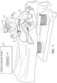
- Fig. 1is a schematic illustration of a medical procedure, according to an embodiment of the present invention.
- Surgical navigation system 20comprises a processor 26, which operates elements of the system, and which communicates with an augmented reality assembly 24, worn by professional 22, that is incorporated in the system.
- Assembly 24comprises, inter alia, an image capturing device 72, also termed herein a camera 72, that has a field of view 74 and that is configured to capture images in the visible spectrum. Functions of system 20, processor 26, and device 72 are described below.
- An assembly similar to augmented reality assembly 24, and its operation,are described in U. S. Patent 9,928,629, to Benishti, et al.
- the medical procedure exemplified hereis performed on a patient 30, and during an initial stage of the procedure professional 22 makes an incision 32 into the patient's back.
- the professionalthen inserts a spinous process clamp 50 into the incision, so that opposing jaws of the clamp are located on opposite sides of the spinous processes.
- the professionalslides the clamp over the vertebral laminas, and adjusts the clamp to grip one or more spinous processes, selected by the professional, of the patient.
- sharp edges of teeth on the jaws of the clampface forward and are configured to cut muscles to the spinous processes, to facilitate insertion of the clamp. This enables lower sides of the jaws to slide on the vertebral laminas.
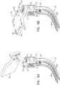
- Fig. 2Aschematically illustrates the situation after clamp 50 has been inserted and adjusted, according to an embodiment of the present invention.
- the figureillustrates that clamp 50 has been attached to grip a spine 40 of patient 30, and to specifically grip spinous processes 42 and 44 of vertebrae of the spine.
- clamp 50comprises studs 54, herein by way of example there are four studs 54, protruding from a proximal surface 58 of a support structure 60 of the clamp.
- Fig. 2Bschematically illustrates how a positioning marker 66 (shown in more detail in Fig. 2C ) is attached to clamp 50, according to an embodiment of the present invention.
- marker 66comprises radiopaque and optically visible elements that are in a known alignment with each other.
- a fluoroscopic image and an visible spectrum image of the markermay be used to register fluoroscopic and visible spectrum frames of reference of the marker, and of the clamp to which the marker is attached.
- studs 54 of clamp 50are configured to mate with apertures 62 of marker 66, so that when mated the marker is seated in one of a multiplicity of selectable positions on surface 58.
- Fig. 2Billustrates the marker attached in one of those positions - to the left of the clamp
- Fig. 5Cshows the marker attached to the right of the clamp.
- the studs and aperturesmay be configured so that there are more than two selectable positions in which marker 66 may be seated on surface 58.
- Fig. 2Cschematically illustrates details of marker 66, according to an embodiment of the present invention.
- Marker 66is formed of a generally rectangular sold substrate 174, which comprises access holes 164 to a set screw 126 (described below with reference to Fig. 4B ), and the holes are configured so that, regardless of the direction of attachment of the marker to the clamp, there is access to the set screw, via one of holes 164, after the marker has been attached.
- marker 66is used as a fiduciary facilitating tracking of, and compensating for, any apparent movement of clamp 50 relative to assembly 24.
- the markeris also used to enable registration of a visible spectrum frame of reference of the marker with a CT frame of reference of the marker.
- marker 66comprises a multiplicity of reflectors 168 that are arranged on an upper face 172 of substrate 174 in a predetermined pattern.
- Reflectors 168reflect visible light, and substrate 174 is typically opaque in the visible spectrum.
- image capturing device 72forms an image of the reflectors, and the image is transferred to processor 26.
- marker 66also comprises a multiplicity of radiopaque elements 170 that are arranged in a known predetermined physical relationship with respect to reflectors 168, and that are typically embedded in substrate 174.
- elements 170are assumed to be a preset distance directly below reflectors 168, and Fig. 2C shows four such elements as spheres.
- the material of substrate 174is selected to be transparent under fluoroscopy.
- reflectors 168 and radiopaque elements 170are comprised of combined single elements that are both reflective in visible light and radiopaque.
- reflectors 168may be formed from aluminum discs.
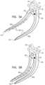
- FIGs. 3A, 3B , 3C, 3D and 3Eare schematic figures illustrating selected elements of clamp 50, according to an embodiment of the present invention.
- Clamp 50comprises two opposing jaws 80A, 80B, which are connected, at proximal regions of the jaws, by a hinge pin 84, also herein termed hinge 84.
- Jaws 80A, 80Bare also herein termed jaws 80.
- At least one of the jawsis able to rotate around hinge pin 84, and in the figures jaw 80A is shown as rotating about the hinge pin, while jaw 80B is fixed with respect to the pin. The rotation enables jaws 80 to transfer in a continuous manner between an open state of the jaws, illustrated in Fig. 3A , and a closed state of the jaws, illustrated in Fig. 3B .
- Hinge pin 84defines a hinge axis 88, and each jaw 80 resides in a respective plane parallel to the hinge axis.
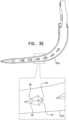
- Fig. 3Cillustrates jaw 80B, and the figure has been drawn so that the plane of the paper of Fig. 3C corresponds to the plane wherein jaw 80B resides.
- jaw 80Bcomprises a first substantially straight proximal region 90, a second substantially straight distal region 94, and a curved intermediate section 97 fixedly connecting the two straight regions.
- Proximal region 90 and distal region 94are both terminating regions of the jaw 80B.
- Jaw 80Acomprises two similar regions and a similar intermediate section that are connected as for jaw 80B.
- the distal regions of the jawsare sufficiently long so that they are able to simultaneously clamp on multiple adjacent spinous processes. In a disclosed embodiment the jaws are approximately 7 cm long.
- an angle ⁇ made by the intersection of the two straight sectionsis approximately 90°.
- angle ⁇may be in the approximate range of 70° - 90°.
- each jaw 80has a multiplicity of teeth 98 on an inner surface of the jaw, and the teeth of the two jaws are configured to be in opposition to each other.
- the opposing teethare configured to intermesh with each other, as is illustrated in Fig. 3D , when the jaws are in their closed state.
- the teethhave a pyramid-like shape, as illustrated in Fig. 3E , wherein the edges of the pyramid are sharp.
- the pyramid of each toothis configured to terminate in a sharp point 94, which facilitates the tooth gripping a spinous process.
- each tooth 98one edge 96 of the pyramid is configured to be sharp and to face forward, so as to enable cutting of the muscles between the spinous processes when the clamp is inserted.
- another edge 100 of the pyramid of each tooth 98is also configured to be sharp, but to face backward, so as to enable cutting of the muscles between the spinous processes on removal of the clamp. It will be understood that the forward-facing sharp edges of the pyramid-shaped teeth facilitate insertion of the clamp into patient 30, and that the backward-facing sharp edges of the pyramid-shaped teeth facilitate removal of the clamp from the patient.
- Distal terminations 102 of each distal section of jaws 80A and 80Bare narrowed by being slightly truncated and rounded, so that the distal tips of the jaws are not sharp. This configuration facilitates insertion of the clamp into soft body tissue, such as muscle or fat.
- edges 104 of internal faces 106 of terminations 102are sharp so as also to facilitate penetration through tissue during insertion of the jaws.
- jaws 80are formed of anodized aluminum, typically black anodized aluminum for biocompatibility. In other embodiments jaws 80 may be formed of other metallic or non-metallic materials, including composites, having substantially the same physical properties as aluminum.
- the proximal region of jaw 80Bcomprises a support structure retaining base 118 ( Figs. 3A, 3B ) which in turn comprises a blind aperture 122.
- base 118 and aperture 122are described below.
- Clamp 50also comprises a verification point 108 which is located in a known, predefined, fixed position on the clamp, and is herein assumed to be fixed, by way of example, to non-movable jaw 80B. However, verification point 108 may be located on other fixed portions of clamp 50, such as support structure 60.
- Point 108is situated on clamp 50 so that after the clamp has been inserted into patient 30, the verification point is visible to professional 22, when illuminated by visible light.
- the verification pointis configured to be identifiable, typically by image segmentation, in a fluoroscopic image, such as a computerized tomography (CT) image of clamp 50.
- CTcomputerized tomography
- verification point 108may comprise a protuberance and/or an indentation in jaw 80B, the protuberance and/or indentation being in the form of any convenient shape such as a cylinder.
- verification point 108may be comprised of a material that is different from the material of clamp 50 wherein the point is located, so long as the material of the point is distinguishable in a fluoroscopic image, and also when viewed in visible light, from the material of the clamp.
- point 108may be formed from a titanium element, such as a spherical bead, that is inserted into the jaw, and that protrudes from the jaw.
- point 108may comprise a void, such as a spherical air pocket, in jaw 80B, and the position of the point may be made visible by an optically visible marking, such as a paint spot, on a surface of the jaw above the void.
- an optically visible markingsuch as a paint spot
- verification point 108Other methods for forming verification point 108, including but not limited to combinations and sub-combinations of those described herein, will be apparent to those having skill in the art, and all such methods are assumed to be comprised within the scope of the present invention.
- Verification pointis used by professional 22 to verify that different elements of system 20 are in registration, as is described in more detail below.
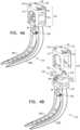
- Figs. 4A and 4Bare schematic figures illustrating further elements of clamp 50, according to an embodiment of the present invention.
- Fig. 4Aillustrates the clamp when assembled, and shows support structure 60 which retains and activates jaws 80 and hinge 84.
- Fig. 4Billustrates support structure 60 with a cover 114 of the structure translated from other elements of the structure. Cover 114 is fixedly attached to support structure retaining base 118 ( Figs. 3A, 3B )
- Support structure 60contains a set screw 126 which is retained by, and rotates within, blind aperture 122 and an open aperture 130 in cover 114.
- Screw 126has an external thread which mates with an internal thread of a nut 134, and sides of the nut touch and slide within walls of cover 114. Thus, rotating screw 126 translates nut 134 vertically within cover 114.
- Nut 134is connected by a lever mechanism 136 to jaw 80A.
- Mechanism 136comprises a first hinge pin 140, a lever rod 144, and a second hinge pin 148.
- Rod 144connects, at its proximal end, via first hinge pin 140, to an aperture 152 in nut 134, so that the rod is able to rotate around the first hinge pin.
- Rod 144connects, at its distal end, via second hinge pin 148 to an aperture 156 in jaw 80A (aperture 156 is also shown in Figs. 3A, 3B .)
- Lever mechanism 136is operated by rotating set screw 126.
- hinge 148 and aperture 156are drawn towards the set screw, so that jaws 80 are in their open state, illustrated in Fig. 3A .
- hinge 148 and aperture 156move away from the set screw, so that jaws 80 are in their closed state, illustrated in Fig. 3B .
- set screw 126as it acts on lever mechanism 136, fixedly maintains jaws 80 in any desired configuration according to the rotation of the set screw.
- a first rotation of screw 126can fixedly maintain the jaws in an open state, and a second rotation can fixedly maintain the jaws in a closed state.
- the jawstypically grip one or more spinous processes.
- the jawsare configured, by selection of the material of the jaws and by selection of the jaw dimensions, to bend so that respective distal terminations 102 of the jaws deflect by up to 1mm from the jaw configuration when they are not gripping the processes.
- the deflection caused by the bending when the jaws grip spinous processesis illustrated schematically in Fig. 7 .
- clamp 50it will be appreciated that the combination of the narrowed distal sections of the jaws, their curved shape, and the relatively long length of the distal straight sections means that even with a small incision 32, clamp 50 can be manipulated to effectively grasp multiple spinous processes of patient 30.
- Figs. 5A, 5B and 5Care schematic figures illustrating the attachment of marker 66 to clamp 50, according to an embodiment of the present invention.
- Fig. 5Aillustrates apertures 62 of the marker mating with studs 54 of the clamp
- Figs. 5B and 5Cillustrate the marker and the clamp when they are attached.
- marker 66may be attached to clamp 50 so that the marker is to the left of the clamp, as shown in Fig. 5B , or to the right of the clamp, as shown in Fig. 5C .
- the markeris attached to the clamp with a screw 160.
- support structure 60is approximately perpendicular to the patient's spine.
- marker 66comprises access holes 164 to set screw 126, and the holes are configured so that, regardless of the direction of attachment of the marker to the clamp, there is access to the set screw, via one of holes 164, after the marker has been attached.
- professional 22may use surgical navigation system 20 ( Fig. 1 ) during the procedure being performed on patient 30, and marker 66 may be used by the system as a fiduciary, enabling any relative movement between the patient and the system to be compensated for.
- processor 26 of the surgical navigation systemmay use image capturing device 72 to recognize an image of the marker itself, or of optical elements such as reflectors 168 of the marker.
- image capturing device 72forms an image of the reflectors, and the image is transferred to processor 26.
- Processor 26uses the captured image to find the position and orientation of marker 66 and of clamp 50, and thus the position and orientation of the patient's spine, onto which clamp 50 is clamped, in a frame of reference defined by the system. Consequently, processor 26 is able to compensate for any relative movement between the marker and the system, which may be caused by movement of patient 30 and/or of professional 22, and the compensation enables the processor to adjust images presented to professional 22 so that the adjusted images appear stable with respect to the patient's spine.
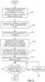
- Fig. 6is a flowchart of steps performed by professional 22 and processor 26 in operation of system 20, and Fig. 7 is a schematic figure illustrating one of the steps, according to an embodiment of the present invention.
- clamp 50is inserted into patient 30 and is attached to one or more spinous processes of the patient, as is described above.
- Marker 66is attached to clamp 50, as described above with reference to Figs. 5A, 5B , 5C .
- the CT imageincludes a fluoroscopic image of verification point 108.
- an optical imaging step 204the professional activates camera 72 to acquire an optical image of the marker, and processor 26 stores the optical image.
- processor 26registers a frame of reference defined by the CT image of marker 66 acquired in step 200 and a frame of reference defined by the optical image of marker 66 acquired in step 204 by methods which are well known in the art. It will be understood that the registration can be performed because reflectors 168, visible in the optical image, and radiopaque elements 170, visible in the CT image, are in a known physical relationship with respect to each other.
- processor 26using camera 72, generates a virtual image of the scene viewed by professional 22, herein assumed to comprise clamp 50, marker 66, and the spine of patient 30.
- the processorregisters a frame of reference of the virtual image with the registered CT and optical frames of reference, and projects the registered virtual image in augmented reality assembly 24 so that it is visible to the professional.
- the registrations produced in steps 206 and/or 208may be inaccurate, and the following steps of the flowchart allow professional 22 to check on the accuracy of the registrations, and if necessary to correct the registrations.
- Fig. 7schematically illustrates clamp 50 inserted into patient 30, and a lower part 78 of the clamp that is within the patient is shown as drawn with broken lines.
- a deflection Dtypically approximately 1 mm, of termination 102 of jaw 80B, caused by bending of the distal region of the jaw when it grips the spinous processes, is illustrated schematically in the figure.
- Jaw 80Awill undergo a similar bending and termination deflection.
- Fig. 7also schematically illustrates camera 72 and field of view 74. It will be understood that the image formed by camera 72 includes images of the upper part of clamp 50 and marker 66, but does not include an image of lower part 78.
- a tool presentation step 210professional 22 introduces a tool 230 ( Fig. 7 ) into field of view 74 of camera 72.
- Tool 230has one or more optical tracking elements 234 located in predefined positions on the tool, and the elements are configured so that an image of tool 230 and elements 234 produced by camera 72 enable processor 26 to track the position of a distal tip 238 of the tool.
- the processorgenerates a virtual image of tool 230, and projects the tool virtual image in augmented reality assembly 24 so that it is visible to professional 26.
- a verification step 214professional 26 touches distal tip 238 on verification point 108. This step may be performed with the virtual image produced by assembly 24 switched on or switched off.
- a decision step 218the professional observes if the images of distal tip 238 and verification point 108 coincide.
- the position of verification point 108which is determined from the CT image acquired in step 200, is incorporated in the registered image being presented to the professional by assembly 24.
- processor 26checks for coincidence.
- decision step 218returns positive, i.e., the two images coincide, the registrations of the system described above are assumed successful, and the flowchart ends.
- decision step 218If decision step 218 returns negative, the registrations of steps 206 and/or 208 are not sufficiently correct, and control continues first to an adjust registration step 220, and from there to decision step 218.
- the processoruses the image generated by camera 72 to determine 3D coordinate values, in the optical frame of reference of marker 66, of distal tip 238 and verification point 108. There is a difference in these coordinate values, illustrated by the negative return of decision step 218, corresponding to a gap between the two values.
- the processorthen adjusts the registrations performed in steps 206 and 208 in order to reduce the gap and returns, iteratively, to decision step 218. The iterations of decision step 218 and adjustment step 220 continue until decision step 218 returns positive.
Landscapes
- Health & Medical Sciences (AREA)
- Surgery (AREA)
- Life Sciences & Earth Sciences (AREA)
- Engineering & Computer Science (AREA)
- Molecular Biology (AREA)
- Public Health (AREA)
- Veterinary Medicine (AREA)
- Biomedical Technology (AREA)
- Heart & Thoracic Surgery (AREA)
- Medical Informatics (AREA)
- Nuclear Medicine, Radiotherapy & Molecular Imaging (AREA)
- Animal Behavior & Ethology (AREA)
- General Health & Medical Sciences (AREA)
- Orthopedic Medicine & Surgery (AREA)
- Reproductive Health (AREA)
- Vascular Medicine (AREA)
- Robotics (AREA)
- Neurology (AREA)
- Oral & Maxillofacial Surgery (AREA)
- Pathology (AREA)
- Surgical Instruments (AREA)
Description
- The present invention relates generally to clamps, and particularly to clamps that may be attached to the spine of a living subject.
- During image guided surgery, it may be important to register elements of a patient, upon whom the surgery is being performed, with equipment generating the image. This is typically the case where the surgery comprises a surgical navigation system, which generates images of portions of the patient that are in registration with the actual portions. Some prior art references that may be used in image guided surgery are provided below.
EP1967155 discloses the use of a medical clamp for providing a reference position for a positioning system for percutaneous interventions and a method for determining a reference position for a positioning system for percutaneous interventions.US5665092 describes a marker for surgical procedures which permits an operating surgeon to mark the place to be operated on accurately in a manner which is as free of pain as possible for the patient.US7107091 describes a surgical device, adapted for use with an image guided surgical system, that is stated to facilitate monitoring inter-dependently mobile bone elements.US8271069 describes a surgical navigation system for navigating a region of a patient that may include a non-invasive dynamic reference frame and/or fiducial marker, sensor tipped instruments, and isolator circuits. The dynamic reference frame may be placed on the patient in a precise location for guiding the instruments.US8737708 states that a patient defines a patient space in which an instrument can be tracked and navigated. An image space is defined by image data that can be registered to the patient space. A tracking device can be connected to a member in a known manner that includes imageable portions that generate image points in the image data. Selected image slices or portions can be used to register reconstructed image data to the patient space.US8784450 describes thoracic/lumbar and cervical spinous process staples which staple/fuse adjacent spinous processes.US9005211 US9011441 US9060757 US9084635 US2015/0282735 describes a device and method for a surgical navigation system comprising a connection unit, a marker carrier unit removably attached to the connection unit, and an attachment unit connected to the connection unit for fixing the device to a body part of a patient.US2016/0022287 describes temporary, radiographically opaque, bone markers having first and second penetration members that are concentric with one another and are configured to pierce bone.US2008/221625 describes a medical clamp, in particular a spinal clamp, that's includes two clamp limbs connected to a grip part.US2004/019263 a surgical device adapted for use with an image guided surgical system to facilitate monitoring inter-dependently mobile bone elements.EP3247297 describes a bone clamp for being attached to a bone.US4944739 describes a pliers-like clamping device having offset bone gripping plates temporarily grips and clamps together two bone segments above and below as diagonal cut at an osteotomy site.- According to a first aspect of the present invention, there is provided an apparatus as set out in the first of the appending independent claims. According to a second aspect of the present invention, there is provided a method as set out in the second of the appending independent claims. Features of various embodiments are set out in the appending dependent claims.
- The present invention will be more fully understood from the following detailed description of the embodiments thereof, taken together with the drawings in which:
Fig. 1 is a schematic illustration of a medical procedure;Fig. 2A schematically illustrates the situation after a clamp has been inserted and adjusted in the medical procedure;Fig. 2B schematically illustrates how a positioning marker is attached to the clamp;Fig. 2C schematically illustrates the positioning marker;Figs. 3A, 3B ,3C, 3D and3E are schematic figures illustrating selected elements of the clamp;Figs. 4A and 4B are schematic figures illustrating further elements of the clamp;Figs. 5A, 5B and5C are schematic figures illustrating the attachment of the marker to the clamp;Fig. 6 is a flowchart of steps performed for the procedure ofFig. 1 ; andFig. 7 is a schematic figure illustrating one of the steps of the flowchart.- Embodiments of the present invention provide apparatus that may be used as a clamp, typically a spinous process clamp that, in contrast to prior art clamps, has two curved jaws. By curving the jaws, the clamp is able to fasten onto two or more spinous processes of a patient, and yet may be inserted into the patient through a relatively small incision.
- A hinge connects the two jaws, and at least one jaw rotates about the hinge. The hinge defines a hinge axis, and each jaw is curved in a respective plane parallel to the hinge axis. In addition, each jaw terminates in a respective narrowed region, the narrowed regions facilitating insertion of the jaws of the clamp into the patient via the incision.
- Each jaw is configured to have sharp teeth, which enable the clamp, when it is closed, to both cut into and effectively grip the spinous processes.
- A clamp support structure retains the two jaws and the hinge. The support structure may be used to manipulate the jaws, after insertion of the jaws into the patient, so that the jaws grip one or more spinous processes of the patient, while the support structure remains external to the patient.
- Once the jaws have gripped the spinous processes of the patient, the support structure of the clamp provides a rigid platform to which may be attached a positioning marker that does not move relative to the patient's spine. The clamp with its attached marker may be used during an image guided surgery procedure, in which a professional performing the procedure uses a surgical navigation system.
- The surgical navigation system may find the position and orientation of the marker, and thus of the clamp, in a frame of reference of the system. Thus any relative movement between the patient and the system, which may be caused by movement of the patient and/or of the professional, may be compensated for.
- The clamp may comprise a verification point, which is configured to be visible when illuminated by visible light, as well as to be identifiable in a fluoroscopic image of the clamp. As is described in more detail below, the professional using the surgical navigation system is able to use the verification point to confirm, and if necessary adjust, different elements of the system in order to achieve correct registration of respective frames of reference of the elements.
- In the following, all directional references (e.g., upper, lower, upward, downward, left, right, top, bottom, above, below, vertical, and horizontal) are only used for identification purposes to aid the reader's understanding of the present invention, and do not create limitations, particularly as to the position, orientation, or use of embodiments of the invention.
- Reference is now made to
Fig. 1 , which is a schematic illustration of a medical procedure, according to an embodiment of the present invention. During the procedure, performed by a professional 22, the professional uses asurgical navigation system 20, which assists the professional in performance of the procedure.Surgical navigation system 20 comprises aprocessor 26, which operates elements of the system, and which communicates with an augmentedreality assembly 24, worn by professional 22, that is incorporated in the system.Assembly 24 comprises,inter alia, an image capturingdevice 72, also termed herein acamera 72, that has a field ofview 74 and that is configured to capture images in the visible spectrum. Functions ofsystem 20,processor 26, anddevice 72 are described below. An assembly similar toaugmented reality assembly 24, and its operation, are described inU. S. Patent 9,928,629, to Benishti, et al. - The medical procedure exemplified here is performed on a
patient 30, and during an initial stage of the procedure professional 22 makes anincision 32 into the patient's back. The professional then inserts a spinous process clamp 50 into the incision, so that opposing jaws of the clamp are located on opposite sides of the spinous processes. The professional then slides the clamp over the vertebral laminas, and adjusts the clamp to grip one or more spinous processes, selected by the professional, of the patient. As is described in more detail below, sharp edges of teeth on the jaws of the clamp face forward and are configured to cut muscles to the spinous processes, to facilitate insertion of the clamp. This enables lower sides of the jaws to slide on the vertebral laminas. Fig. 2A schematically illustrates the situation afterclamp 50 has been inserted and adjusted, according to an embodiment of the present invention. The figure illustrates thatclamp 50 has been attached to grip aspine 40 ofpatient 30, and to specifically grip spinous processes 42 and 44 of vertebrae of the spine. As shown inFig. 2A , clamp 50 comprisesstuds 54, herein by way of example there are fourstuds 54, protruding from aproximal surface 58 of asupport structure 60 of the clamp.Fig. 2B schematically illustrates how a positioning marker 66 (shown in more detail inFig. 2C ) is attached to clamp 50, according to an embodiment of the present invention. As is explained below,marker 66 comprises radiopaque and optically visible elements that are in a known alignment with each other. Thus. a fluoroscopic image and an visible spectrum image of the marker may be used to register fluoroscopic and visible spectrum frames of reference of the marker, and of the clamp to which the marker is attached.- As is illustrated schematically in
Fig. 2B ,studs 54 ofclamp 50 are configured to mate withapertures 62 ofmarker 66, so that when mated the marker is seated in one of a multiplicity of selectable positions onsurface 58. In the embodiment described herein there are two selectable positions, andFig. 2B illustrates the marker attached in one of those positions - to the left of the clamp (Fig. 5C shows the marker attached to the right of the clamp). However, it will be understood that the studs and apertures may be configured so that there are more than two selectable positions in whichmarker 66 may be seated onsurface 58. Fig. 2C schematically illustrates details ofmarker 66, according to an embodiment of the present invention.Marker 66 is formed of a generally rectangular soldsubstrate 174, which comprises access holes 164 to a set screw 126 (described below with reference toFig. 4B ), and the holes are configured so that, regardless of the direction of attachment of the marker to the clamp, there is access to the set screw, via one ofholes 164, after the marker has been attached.- During the procedure performed by professional 22,
marker 66 is used as a fiduciary facilitating tracking of, and compensating for, any apparent movement ofclamp 50 relative toassembly 24. The marker is also used to enable registration of a visible spectrum frame of reference of the marker with a CT frame of reference of the marker. - In order to act as a fiduciary,
marker 66 comprises a multiplicity ofreflectors 168 that are arranged on anupper face 172 ofsubstrate 174 in a predetermined pattern.Reflectors 168 reflect visible light, andsubstrate 174 is typically opaque in the visible spectrum. When the reflectors are illuminated, by a projector (not shown) ofsurgical navigation system 20 and/or by ambient visible light,image capturing device 72 forms an image of the reflectors, and the image is transferred toprocessor 26. - To act as a registration device,
marker 66 also comprises a multiplicity ofradiopaque elements 170 that are arranged in a known predetermined physical relationship with respect toreflectors 168, and that are typically embedded insubstrate 174. By way of example,elements 170 are assumed to be a preset distance directly belowreflectors 168, andFig. 2C shows four such elements as spheres. The material ofsubstrate 174 is selected to be transparent under fluoroscopy. - In some
embodiments reflectors 168 andradiopaque elements 170, rather than comprising separate entities as describe above, are comprised of combined single elements that are both reflective in visible light and radiopaque. For example,reflectors 168 may be formed from aluminum discs. Figs. 3A, 3B ,3C, 3D and3E are schematic figures illustrating selected elements ofclamp 50, according to an embodiment of the present invention.Clamp 50 comprises two opposingjaws hinge pin 84, also herein termedhinge 84.Jaws hinge pin 84, and in thefigures jaw 80A is shown as rotating about the hinge pin, whilejaw 80B is fixed with respect to the pin. The rotation enables jaws 80 to transfer in a continuous manner between an open state of the jaws, illustrated inFig. 3A , and a closed state of the jaws, illustrated inFig. 3B .Hinge pin 84 defines ahinge axis 88, and each jaw 80 resides in a respective plane parallel to the hinge axis.Fig. 3C illustratesjaw 80B, and the figure has been drawn so that the plane of the paper ofFig. 3C corresponds to the plane whereinjaw 80B resides.- Each jaw 80 is curved within its respective plane. Thus, as illustrated in
Fig. 3C ,jaw 80B comprises a first substantially straightproximal region 90, a second substantially straightdistal region 94, and a curvedintermediate section 97 fixedly connecting the two straight regions.Proximal region 90 anddistal region 94 are both terminating regions of thejaw 80B.Jaw 80A comprises two similar regions and a similar intermediate section that are connected as forjaw 80B. Typically, the distal regions of the jaws are sufficiently long so that they are able to simultaneously clamp on multiple adjacent spinous processes. In a disclosed embodiment the jaws are approximately 7 cm long. - In one embodiment an angle θ made by the intersection of the two straight sections is approximately 90°. However, in other embodiments, angle θ may be in the approximate range of 70° - 90°.
- Typically each jaw 80 has a multiplicity of
teeth 98 on an inner surface of the jaw, and the teeth of the two jaws are configured to be in opposition to each other. In one embodiment the opposing teeth are configured to intermesh with each other, as is illustrated inFig. 3D , when the jaws are in their closed state. - In a disclosed embodiment the teeth have a pyramid-like shape, as illustrated in
Fig. 3E , wherein the edges of the pyramid are sharp. In this case the pyramid of each tooth is configured to terminate in asharp point 94, which facilitates the tooth gripping a spinous process. - In addition, for each
tooth 98 oneedge 96 of the pyramid is configured to be sharp and to face forward, so as to enable cutting of the muscles between the spinous processes when the clamp is inserted. Furthermore, anotheredge 100 of the pyramid of eachtooth 98 is also configured to be sharp, but to face backward, so as to enable cutting of the muscles between the spinous processes on removal of the clamp. It will be understood that the forward-facing sharp edges of the pyramid-shaped teeth facilitate insertion of the clamp intopatient 30, and that the backward-facing sharp edges of the pyramid-shaped teeth facilitate removal of the clamp from the patient. Distal terminations 102 of each distal section ofjaws terminations 102 are sharp so as also to facilitate penetration through tissue during insertion of the jaws.- In one embodiment jaws 80 are formed of anodized aluminum, typically black anodized aluminum for biocompatibility. In other embodiments jaws 80 may be formed of other metallic or non-metallic materials, including composites, having substantially the same physical properties as aluminum.
- The proximal region of
jaw 80B comprises a support structure retaining base 118 (Figs. 3A, 3B ) which in turn comprises ablind aperture 122. The functions ofbase 118 andaperture 122 are described below. Clamp 50 also comprises averification point 108 which is located in a known, predefined, fixed position on the clamp, and is herein assumed to be fixed, by way of example, tonon-movable jaw 80B. However,verification point 108 may be located on other fixed portions ofclamp 50, such assupport structure 60.Point 108 is situated onclamp 50 so that after the clamp has been inserted intopatient 30, the verification point is visible to professional 22, when illuminated by visible light. In addition to being visible to professional 22, the verification point is configured to be identifiable, typically by image segmentation, in a fluoroscopic image, such as a computerized tomography (CT) image ofclamp 50.- In order to be identifiable as described above,
verification point 108 may comprise a protuberance and/or an indentation injaw 80B, the protuberance and/or indentation being in the form of any convenient shape such as a cylinder. Alternatively or additionally,verification point 108 may be comprised of a material that is different from the material ofclamp 50 wherein the point is located, so long as the material of the point is distinguishable in a fluoroscopic image, and also when viewed in visible light, from the material of the clamp. For example, ifjaw 80B is formed from aluminum,point 108 may be formed from a titanium element, such as a spherical bead, that is inserted into the jaw, and that protrudes from the jaw. As another example,point 108 may comprise a void, such as a spherical air pocket, injaw 80B, and the position of the point may be made visible by an optically visible marking, such as a paint spot, on a surface of the jaw above the void. - Other methods for forming
verification point 108, including but not limited to combinations and sub-combinations of those described herein, will be apparent to those having skill in the art, and all such methods are assumed to be comprised within the scope of the present invention. - Verification point is used by professional 22 to verify that different elements of
system 20 are in registration, as is described in more detail below. Figs. 4A and 4B are schematic figures illustrating further elements ofclamp 50, according to an embodiment of the present invention.Fig. 4A illustrates the clamp when assembled, and showssupport structure 60 which retains and activates jaws 80 andhinge 84.Fig. 4B illustratessupport structure 60 with acover 114 of the structure translated from other elements of the structure. Cover 114 is fixedly attached to support structure retaining base 118 (Figs. 3A, 3B )Support structure 60 contains aset screw 126 which is retained by, and rotates within,blind aperture 122 and anopen aperture 130 incover 114.Screw 126 has an external thread which mates with an internal thread of anut 134, and sides of the nut touch and slide within walls ofcover 114. Thus,rotating screw 126 translatesnut 134 vertically withincover 114.Nut 134 is connected by alever mechanism 136 tojaw 80A.Mechanism 136 comprises afirst hinge pin 140, alever rod 144, and asecond hinge pin 148.Rod 144 connects, at its proximal end, viafirst hinge pin 140, to anaperture 152 innut 134, so that the rod is able to rotate around the first hinge pin.Rod 144 connects, at its distal end, viasecond hinge pin 148 to anaperture 156 injaw 80A (aperture 156 is also shown inFigs. 3A, 3B .)Lever mechanism 136 is operated by rotating setscrew 126. When the screw is rotated so thatnut 134 has translated in an upper direction withinstructure 60,hinge 148 andaperture 156 are drawn towards the set screw, so that jaws 80 are in their open state, illustrated inFig. 3A . When setscrew 126 is rotated so thatnut 134 has translated in a lower direction withinstructure 60,hinge 148 andaperture 156 move away from the set screw, so that jaws 80 are in their closed state, illustrated inFig. 3B .- It will be understood that
set screw 126, as it acts onlever mechanism 136, fixedly maintains jaws 80 in any desired configuration according to the rotation of the set screw. Thus a first rotation ofscrew 126 can fixedly maintain the jaws in an open state, and a second rotation can fixedly maintain the jaws in a closed state. - During the procedure referred to above, in their closed state the jaws typically grip one or more spinous processes. In order to firmly grip the processes in their closed state, in an embodiment the jaws are configured, by selection of the material of the jaws and by selection of the jaw dimensions, to bend so that respective
distal terminations 102 of the jaws deflect by up to 1mm from the jaw configuration when they are not gripping the processes. The deflection caused by the bending when the jaws grip spinous processes is illustrated schematically inFig. 7 . - From the descriptions of
clamp 50 above, it will be appreciated that the combination of the narrowed distal sections of the jaws, their curved shape, and the relatively long length of the distal straight sections means that even with asmall incision 32, clamp 50 can be manipulated to effectively grasp multiple spinous processes ofpatient 30. Figs. 5A, 5B and5C are schematic figures illustrating the attachment ofmarker 66 to clamp 50, according to an embodiment of the present invention.Fig. 5A illustratesapertures 62 of the marker mating withstuds 54 of the clamp, andFigs. 5B and5C illustrate the marker and the clamp when they are attached. In the embodiment illustrated,marker 66 may be attached to clamp 50 so that the marker is to the left of the clamp, as shown inFig. 5B , or to the right of the clamp, as shown inFig. 5C . The marker is attached to the clamp with ascrew 160.- During a procedure professional 22 can select which
direction marker 66 is in so as to have best access to the patient. Typically, after insertion of jaws 80 into the patient,support structure 60 is approximately perpendicular to the patient's spine. - As is described above,
marker 66 comprises access holes 164 to setscrew 126, and the holes are configured so that, regardless of the direction of attachment of the marker to the clamp, there is access to the set screw, via one ofholes 164, after the marker has been attached. - As is also described above, professional 22 may use surgical navigation system 20 (
Fig. 1 ) during the procedure being performed onpatient 30, andmarker 66 may be used by the system as a fiduciary, enabling any relative movement between the patient and the system to be compensated for. In order to operate as a fiduciary,processor 26 of the surgical navigation system may useimage capturing device 72 to recognize an image of the marker itself, or of optical elements such asreflectors 168 of the marker. - Thus, when
reflectors 168 are illuminated by a projector (not shown) ofsurgical navigation system 20, and/or are illuminated by ambient visible light,image capturing device 72 forms an image of the reflectors, and the image is transferred toprocessor 26.Processor 26 uses the captured image to find the position and orientation ofmarker 66 and ofclamp 50, and thus the position and orientation of the patient's spine, onto which clamp 50 is clamped, in a frame of reference defined by the system. Consequently,processor 26 is able to compensate for any relative movement between the marker and the system, which may be caused by movement ofpatient 30 and/or of professional 22, and the compensation enables the processor to adjust images presented to professional 22 so that the adjusted images appear stable with respect to the patient's spine. - Other methods for using
marker 66, to compensate for any movement ofpatient 30, will be apparent to those having ordinary skill in the art, and all such methods are assumed to be comprised within the scope of the present invention. Fig. 6 is a flowchart of steps performed by professional 22 andprocessor 26 in operation ofsystem 20, andFig. 7 is a schematic figure illustrating one of the steps, according to an embodiment of the present invention. In aninitial step 200clamp 50 is inserted intopatient 30 and is attached to one or more spinous processes of the patient, as is described above.Marker 66 is attached to clamp 50, as described above with reference toFigs. 5A, 5B ,5C .- Once the clamp and marker are attached, a CT image of the patient, the clamp, and the marker is acquired, and
processor 26 stores the image. The CT image includes a fluoroscopic image ofverification point 108. - In an
optical imaging step 204 the professional activatescamera 72 to acquire an optical image of the marker, andprocessor 26 stores the optical image. - In a
registration step 206,processor 26 registers a frame of reference defined by the CT image ofmarker 66 acquired instep 200 and a frame of reference defined by the optical image ofmarker 66 acquired instep 204 by methods which are well known in the art. It will be understood that the registration can be performed becausereflectors 168, visible in the optical image, andradiopaque elements 170, visible in the CT image, are in a known physical relationship with respect to each other. - In a
virtual image step 208,processor 26, usingcamera 72, generates a virtual image of the scene viewed by professional 22, herein assumed to compriseclamp 50,marker 66, and the spine ofpatient 30. The processor registers a frame of reference of the virtual image with the registered CT and optical frames of reference, and projects the registered virtual image inaugmented reality assembly 24 so that it is visible to the professional. - The registrations produced in
steps 206 and/or 208 may be inaccurate, and the following steps of the flowchart allow professional 22 to check on the accuracy of the registrations, and if necessary to correct the registrations. Fig. 7 schematically illustratesclamp 50 inserted intopatient 30, and alower part 78 of the clamp that is within the patient is shown as drawn with broken lines. For simplicity the spinous processes of the patient are not shown in the figure. A deflection D, typically approximately 1 mm, oftermination 102 ofjaw 80B, caused by bending of the distal region of the jaw when it grips the spinous processes, is illustrated schematically in the figure.Jaw 80A will undergo a similar bending and termination deflection.Fig. 7 also schematically illustratescamera 72 and field ofview 74. It will be understood that the image formed bycamera 72 includes images of the upper part ofclamp 50 andmarker 66, but does not include an image oflower part 78.- In a
tool presentation step 210, professional 22 introduces a tool 230 (Fig. 7 ) into field ofview 74 ofcamera 72.Tool 230 has one or moreoptical tracking elements 234 located in predefined positions on the tool, and the elements are configured so that an image oftool 230 andelements 234 produced bycamera 72 enableprocessor 26 to track the position of adistal tip 238 of the tool. - The processor generates a virtual image of
tool 230, and projects the tool virtual image inaugmented reality assembly 24 so that it is visible to professional 26. - In a
verification step 214, professional 26 touchesdistal tip 238 onverification point 108. This step may be performed with the virtual image produced byassembly 24 switched on or switched off. - In a
decision step 218, the professional observes if the images ofdistal tip 238 andverification point 108 coincide. In an embodiment, the position ofverification point 108, which is determined from the CT image acquired instep 200, is incorporated in the registered image being presented to the professional byassembly 24. Alternatively, rather than the professional checking for coincidence,processor 26 checks for coincidence. - If
decision step 218 returns positive, i.e., the two images coincide, the registrations of the system described above are assumed successful, and the flowchart ends. - If
decision step 218 returns negative, the registrations ofsteps 206 and/or 208 are not sufficiently correct, and control continues first to an adjustregistration step 220, and from there todecision step 218. - In adjust
registration step 220 the processor uses the image generated bycamera 72 to determine 3D coordinate values, in the optical frame of reference ofmarker 66, ofdistal tip 238 andverification point 108. There is a difference in these coordinate values, illustrated by the negative return ofdecision step 218, corresponding to a gap between the two values. The processor then adjusts the registrations performed insteps decision step 218. The iterations ofdecision step 218 andadjustment step 220 continue untildecision step 218 returns positive. - It will be appreciated that the embodiments described above are cited by way of example, and that the present invention is not limited to what has been particularly shown and described hereinabove. Rather, the scope of the present invention as defined in the appending claims includes both combinations and subcombinations of the various features described hereinabove, as well as variations and modifications thereof which would occur to persons skilled in the art upon reading the foregoing description and which are not disclosed in the prior art.
Claims (13)
- Apparatus, comprising:a hinge (84), defining a hinge axis (88);a pair of opposing jaws (80A, 80B) terminating at respective proximal regions and distal regions, wherein the proximal regions are connected to the hinge so that at least one of the jaws is configured to rotate about the hinge between a closed state and an open state of the jaws, and the jaws terminate in respective narrowed ends at the respective distal regions;a support structure (60), configured to retain the hinge and the pair of opposing jaws; anda multiplicity of sharp teeth (98) disposed on respective inner surfaces of the opposing jaws;wherein the jaws are curved in respective planes parallel to the hinge axis;wherein a first curved jaw of the pair defines and resides in a first plane of the respective planes;wherein a second curved jaw of the pair defines and resides in a second plane of the respective planes;wherein the jaws in the closed state are configured to grip a plurality of vertebrae;characterized in that the support structure comprises and encloses a lever mechanism attached to the proximal region of the at least one of the jaws, the mechanism having a first configuration fixedly maintaining the jaws in the open state, and a second configuration fixedly maintaining the jaws in the closed state; andin that each of the sharp teeth has a pyramid-like configuration.
- The apparatus according to claim 1, wherein the pair of opposing jaws comprises a jaw fixed with respect to the hinge, the apparatus further comprising a verification point located in a fixed position within an element of the apparatus consisting of one of the fixed jaw and the support structure, wherein the verification point is identifiable in a fluoroscopic image of the element.
- The apparatus according to claim 1, and comprising a detachable positioning marker, configured to be fixedly and rigidly attached in one of a plurality of positions to the support structure.
- The apparatus according to claim 3, and comprising a surgical navigation system, an image capturing device therein, and a processor, wherein the surgical navigation system is remote from the positioning marker, and wherein the image capturing device is configured to capture an image of the marker and wherein the processor is configured to analyze the image so as determine the position and orientation of the marker in a frame of reference defined by the system.
- The apparatus according to claim 1, wherein each of the sharp teeth terminates in a sharp point.
- The apparatus according to claim 1, wherein each of the sharp teeth comprises a proximally-facing sharp edge.
- The apparatus according to claim 1, wherein each of the sharp teeth comprises a distally-facing sharp edge.
- The apparatus according to any of claims 1-7, wherein the respective proximal regions and distal regions comprise straight regions connected by a curved intermediate section.
- The apparatus according to claim 8, wherein an angle between the straight sections is in a range from 70° - 90°.
- The apparatus according to any of claims 1-7, wherein the respective narrowed ends are rounded and truncated.
- The apparatus according to any of claims 1-7, wherein the jaws are configured so that when the jaws grip the one or more sections of the vertebrae the jaws bend so that respective distal terminations of the distal regions deflect by up to 1 mm.
- A method, comprising:defining a hinge axis (88) for a hinge (84);providing a pair of opposing jaws (80A, 80B) terminating at respective proximal regions and distal regions;connecting the proximal regions to the hinge so that at least one of the jaws is configured to rotate about the hinge between a closed state and an open state of the jaws;configuring the jaws to terminate in respective narrowed ends at the respective distal regions;retaining the hinge and the pair of opposing jaws with a support structure (60); anddisposing a multiplicity of sharp teeth (98) on respective inner surfaces of the opposing jaws;wherein the jaws are curved in respective planes parallel to the hinge axis;wherein a first curved jaw of the pair defines and resides in a first plane of the respective planes;wherein a second curved jaw of the pair defines and resides in a second plane of the respective planes;wherein the jaws in the closed state are configured to grip a plurality of vertebrae;characterized in that the support structure comprises and encloses a lever mechanism attached to the proximal region of the at least one of the jaws, the mechanism having a first configuration fixedly maintaining the jaws in the open state, and a second configuration fixedly maintaining the jaws in the closed state; andin that each of the sharp teeth has a pyramid-like configuration.
- The method according to claim 12, wherein the pair of opposing jaws comprises a jaw fixed with respect to the hinge, the method further comprising locating a verification point in a fixed position within an element consisting of one of the fixed jaw and the support structure, wherein the verification point is identifiable in a fluoroscopic image of the element.
Priority Applications (1)
| Application Number | Priority Date | Filing Date | Title |
|---|---|---|---|
| EP23200578.5AEP4335391A1 (en) | 2017-12-07 | 2018-09-04 | Spinous process clamp |
Applications Claiming Priority (1)
| Application Number | Priority Date | Filing Date | Title |
|---|---|---|---|
| US201762595598P | 2017-12-07 | 2017-12-07 |
Related Child Applications (1)
| Application Number | Title | Priority Date | Filing Date |
|---|---|---|---|
| EP23200578.5ADivisionEP4335391A1 (en) | 2017-12-07 | 2018-09-04 | Spinous process clamp |
Publications (3)
| Publication Number | Publication Date |
|---|---|
| EP3494903A1 EP3494903A1 (en) | 2019-06-12 |
| EP3494903B1true EP3494903B1 (en) | 2023-11-01 |
| EP3494903C0 EP3494903C0 (en) | 2023-11-01 |
Family
ID=63491537
Family Applications (2)
| Application Number | Title | Priority Date | Filing Date |
|---|---|---|---|
| EP18192544.7AActiveEP3494903B1 (en) | 2017-12-07 | 2018-09-04 | Spinous process clamp |
| EP23200578.5APendingEP4335391A1 (en) | 2017-12-07 | 2018-09-04 | Spinous process clamp |
Family Applications After (1)
| Application Number | Title | Priority Date | Filing Date |
|---|---|---|---|
| EP23200578.5APendingEP4335391A1 (en) | 2017-12-07 | 2018-09-04 | Spinous process clamp |
Country Status (2)
| Country | Link |
|---|---|
| US (1) | US10835296B2 (en) |
| EP (2) | EP3494903B1 (en) |
Families Citing this family (20)
| Publication number | Priority date | Publication date | Assignee | Title |
|---|---|---|---|---|
| GB2536650A (en) | 2015-03-24 | 2016-09-28 | Augmedics Ltd | Method and system for combining video-based and optic-based augmented reality in a near eye display |
| US20230329801A1 (en)* | 2017-12-07 | 2023-10-19 | Augmedics Ltd. | Spinous Process Clamp |
| US11980507B2 (en) | 2018-05-02 | 2024-05-14 | Augmedics Ltd. | Registration of a fiducial marker for an augmented reality system |
| WO2020028649A1 (en)* | 2018-08-02 | 2020-02-06 | Siegenthaler Michael | Sideways or tangentially applicable surgical clip for bleeding control |
| US11766296B2 (en) | 2018-11-26 | 2023-09-26 | Augmedics Ltd. | Tracking system for image-guided surgery |
| US11980506B2 (en)* | 2019-07-29 | 2024-05-14 | Augmedics Ltd. | Fiducial marker |
| US12178666B2 (en) | 2019-07-29 | 2024-12-31 | Augmedics Ltd. | Fiducial marker |
| US11382712B2 (en) | 2019-12-22 | 2022-07-12 | Augmedics Ltd. | Mirroring in image guided surgery |
| US11389252B2 (en) | 2020-06-15 | 2022-07-19 | Augmedics Ltd. | Rotating marker for image guided surgery |
| US12239385B2 (en) | 2020-09-09 | 2025-03-04 | Augmedics Ltd. | Universal tool adapter |
| EP4225196A4 (en)* | 2020-10-12 | 2024-10-02 | Augmedics Ltd. | SPINOUS PROCESS CLAMP |
| EP3988046B1 (en) | 2020-10-22 | 2025-07-09 | Cyber Surgery S.L. | Bone clamp |
| US12369987B2 (en) | 2020-12-09 | 2025-07-29 | Pacific Medical Device Consulting LLC | Self-locating, active markers for navigated, augmented reality, or robotic surgery |
| US11896445B2 (en) | 2021-07-07 | 2024-02-13 | Augmedics Ltd. | Iliac pin and adapter |
| US12150821B2 (en) | 2021-07-29 | 2024-11-26 | Augmedics Ltd. | Rotating marker and adapter for image-guided surgery |
| US20240307129A1 (en)* | 2021-08-04 | 2024-09-19 | University Of Florida Research Foundation, Incorporated | Neurosurgical navigation system reference array apparatus |
| WO2023021448A1 (en) | 2021-08-18 | 2023-02-23 | Augmedics Ltd. | Augmented-reality surgical system using depth sensing |
| EP4511809A1 (en) | 2022-04-21 | 2025-02-26 | Augmedics Ltd. | Systems and methods for medical image visualization |
| IL319523A (en) | 2022-09-13 | 2025-05-01 | Augmedics Ltd | Augmented reality eyewear for image-guided medical intervention |
| US20250032192A1 (en)* | 2023-07-26 | 2025-01-30 | Depuy Ireland Unlimited Company | Play-free fast locking navigation tracker connection |
Citations (1)
| Publication number | Priority date | Publication date | Assignee | Title |
|---|---|---|---|---|
| EP3247297B1 (en)* | 2016-03-17 | 2018-08-01 | Brainlab AG | Bone clamp |
Family Cites Families (41)
| Publication number | Priority date | Publication date | Assignee | Title |
|---|---|---|---|---|
| US3101715A (en)* | 1961-07-12 | 1963-08-27 | Mueller & Company V | Non-crushing clamp |
| US4711512A (en) | 1985-07-12 | 1987-12-08 | Environmental Research Institute Of Michigan | Compact head-up display |
| US4944739A (en)* | 1989-03-24 | 1990-07-31 | Torre Randall J | Bone gripping fixation clamp |
| US6675040B1 (en)* | 1991-01-28 | 2004-01-06 | Sherwood Services Ag | Optical object tracking system |
| US5147365A (en)* | 1991-08-19 | 1992-09-15 | Intermedics Orthopedics, Inc. | Patellar osteotomy guide |
| DE4306277C2 (en) | 1993-03-01 | 2000-11-02 | Leibinger Gmbh | Operation marking tool |
| US6847336B1 (en) | 1996-10-02 | 2005-01-25 | Jerome H. Lemelson | Selectively controllable heads-up display system |
| US6785323B1 (en)* | 1999-11-22 | 2004-08-31 | Ipr Licensing, Inc. | Variable rate coding for forward link |
| US7366562B2 (en) | 2003-10-17 | 2008-04-29 | Medtronic Navigation, Inc. | Method and apparatus for surgical navigation |
| US6546935B2 (en)* | 2000-04-27 | 2003-04-15 | Atricure, Inc. | Method for transmural ablation |
| US6856324B2 (en) | 2001-03-27 | 2005-02-15 | Siemens Corporate Research, Inc. | Augmented reality guided instrument positioning with guiding graphics |
| US7107091B2 (en)* | 2002-07-25 | 2006-09-12 | Orthosoft Inc. | Multiple bone tracking |
| CN101816588A (en) | 2004-02-20 | 2010-09-01 | 赫克托·O·帕切科 | Adjustable awl for punching |
| US8784450B2 (en) | 2005-04-12 | 2014-07-22 | Mosheh T. MOSKOWITZ | Interarticulating spinous and transverse process staples for spinal fusion |
| US9011441B2 (en) | 2006-02-17 | 2015-04-21 | Paradigm Spine, L.L.C. | Method and system for performing interspinous space preparation for receiving an implant |
| DE202006019649U1 (en) | 2006-12-22 | 2007-08-16 | Brainlab Ag | Navigated application guide for targeted spinal drug administration |
| DE102007011568A1 (en)* | 2007-03-08 | 2008-09-11 | Cas Innovations Ag | Medical clamp, in particular spinal clamp |
| US20080253526A1 (en) | 2007-04-11 | 2008-10-16 | Searete Llc, A Limited Liability Corporation Of The State Of Delaware | Geometric compton scattered x-ray visualizing, imaging, or information providing |
| US7724871B2 (en) | 2007-04-11 | 2010-05-25 | The Invention Science Fund I, Llc | Compton scattered X-ray visualization, imaging, or information provider in soft matter such as tissue, organs, or blood, and/or in hard matter such as bones or teeth |
| US20090062869A1 (en) | 2007-08-28 | 2009-03-05 | Perception Raisonnement Action En Medecine | Minimally invasive bone fixation clamp for navigated surgeries |
| US20100149073A1 (en) | 2008-11-02 | 2010-06-17 | David Chaum | Near to Eye Display System and Appliance |
| US9060757B2 (en) | 2008-05-05 | 2015-06-23 | Ranier Limited | Distractor |
| US8737708B2 (en) | 2009-05-13 | 2014-05-27 | Medtronic Navigation, Inc. | System and method for automatic registration between an image and a subject |
| US20100292693A1 (en) | 2009-05-15 | 2010-11-18 | Daniel Nehls | Spinal Marker System and Methods of Use |
| US8348127B2 (en)* | 2010-04-07 | 2013-01-08 | Covidien Lp | Surgical fastener applying apparatus |
| CA2797302C (en) | 2010-04-28 | 2019-01-15 | Ryerson University | System and methods for intraoperative guidance feedback |
| US20110306873A1 (en) | 2010-05-07 | 2011-12-15 | Krishna Shenai | System for performing highly accurate surgery |
| US8941559B2 (en) | 2010-09-21 | 2015-01-27 | Microsoft Corporation | Opacity filter for display device |
| US8718346B2 (en) | 2011-10-05 | 2014-05-06 | Saferay Spine Llc | Imaging system and method for use in surgical and interventional medical procedures |
| US9123155B2 (en) | 2011-08-09 | 2015-09-01 | Covidien Lp | Apparatus and method for using augmented reality vision system in surgical procedures |
| US9084635B2 (en) | 2011-10-07 | 2015-07-21 | Regents Of The University Of Minnesota | Intraoperative spinal stabilization |
| US20150084990A1 (en) | 2013-04-07 | 2015-03-26 | Laor Consulting Llc | Augmented reality medical procedure aid |
| US8922589B2 (en) | 2013-04-07 | 2014-12-30 | Laor Consulting Llc | Augmented reality apparatus |
| US20150282735A1 (en) | 2014-04-04 | 2015-10-08 | Izi Medical Products,Llc | Reference device for surgical navigation system |
| US10424115B2 (en) | 2014-04-24 | 2019-09-24 | Christof Ellerbrock | Head-worn platform for integrating virtuality with reality |
| FR3021518A1 (en) | 2014-05-27 | 2015-12-04 | Francois Duret | VISUALIZATION DEVICE FOR FACILITATING MEASUREMENT AND 3D DIAGNOSIS BY OPTICAL FOOTPRINT IN DENTISTRY |
| US20160086380A1 (en) | 2014-09-22 | 2016-03-24 | Invuity, Inc | Hyperspectral imager |
| US10154239B2 (en) | 2014-12-30 | 2018-12-11 | Onpoint Medical, Inc. | Image-guided surgery with surface reconstruction and augmented reality visualization |
| JP2018516718A (en) | 2015-03-01 | 2018-06-28 | アリス エムディー, インコーポレイテッドARIS MD, Inc. | Morphological diagnosis of extended reality |
| US20160324580A1 (en) | 2015-03-23 | 2016-11-10 | Justin Esterberg | Systems and methods for assisted surgical navigation |
| GB2536650A (en) | 2015-03-24 | 2016-09-28 | Augmedics Ltd | Method and system for combining video-based and optic-based augmented reality in a near eye display |
- 2018
- 2018-09-04EPEP18192544.7Apatent/EP3494903B1/enactiveActive
- 2018-09-04USUS16/120,480patent/US10835296B2/enactiveActive
- 2018-09-04EPEP23200578.5Apatent/EP4335391A1/enactivePending
Patent Citations (1)
| Publication number | Priority date | Publication date | Assignee | Title |
|---|---|---|---|---|
| EP3247297B1 (en)* | 2016-03-17 | 2018-08-01 | Brainlab AG | Bone clamp |
Also Published As
| Publication number | Publication date |
|---|---|
| US10835296B2 (en) | 2020-11-17 |
| EP3494903A1 (en) | 2019-06-12 |
| EP3494903C0 (en) | 2023-11-01 |
| EP4335391A1 (en) | 2024-03-13 |
| US20190175228A1 (en) | 2019-06-13 |
Similar Documents
| Publication | Publication Date | Title |
|---|---|---|
| EP3494903B1 (en) | Spinous process clamp | |
| US20230329801A1 (en) | Spinous Process Clamp | |
| US20210022828A1 (en) | Spinous process clamp | |
| EP4225196A1 (en) | Spinous process clamp | |
| IL262864A (en) | Spinous process clamp | |
| US12295762B2 (en) | Method for verifying hard tissue location using implant imaging | |
| CN114144137B (en) | Fiducial markers | |
| US12178666B2 (en) | Fiducial marker | |
| JP6843851B2 (en) | Device for minimally invasive attachment of tracker and / or alignment phantom to patient bone | |
| Nolte et al. | A new approach to computer-aided spine surgery: fluoroscopy-based surgical navigation | |
| CN108135662B (en) | Fluoroscopic navigation system for navigating a tool relative to a medical image | |
| EP2723262B1 (en) | Assembly for manipulating a bone comprising a position tracking system | |
| CN103561665B (en) | For implanting the boring cover of pedicle screw | |
| US9517107B2 (en) | Surgical targeting system and method | |
| JP2020511231A (en) | Hip replacement navigation system and method | |
| US11278355B2 (en) | Modular fluoro-navigation instrument | |
| US10165998B2 (en) | Method and system for determining an angle between two parts of a bone | |
| US20080013678A1 (en) | Device for Placing Instruments or Implants in Body Organs |
Legal Events
| Date | Code | Title | Description |
|---|---|---|---|
| PUAI | Public reference made under article 153(3) epc to a published international application that has entered the european phase | Free format text:ORIGINAL CODE: 0009012 | |
| STAA | Information on the status of an ep patent application or granted ep patent | Free format text:STATUS: REQUEST FOR EXAMINATION WAS MADE | |
| 17P | Request for examination filed | Effective date:20180904 | |
| AK | Designated contracting states | Kind code of ref document:A1 Designated state(s):AL AT BE BG CH CY CZ DE DK EE ES FI FR GB GR HR HU IE IS IT LI LT LU LV MC MK MT NL NO PL PT RO RS SE SI SK SM TR | |
| AX | Request for extension of the european patent | Extension state:BA ME | |
| STAA | Information on the status of an ep patent application or granted ep patent | Free format text:STATUS: EXAMINATION IS IN PROGRESS | |
| 17Q | First examination report despatched | Effective date:20200128 | |
| GRAP | Despatch of communication of intention to grant a patent | Free format text:ORIGINAL CODE: EPIDOSNIGR1 | |
| STAA | Information on the status of an ep patent application or granted ep patent | Free format text:STATUS: GRANT OF PATENT IS INTENDED | |
| INTG | Intention to grant announced | Effective date:20230120 | |
| GRAJ | Information related to disapproval of communication of intention to grant by the applicant or resumption of examination proceedings by the epo deleted | Free format text:ORIGINAL CODE: EPIDOSDIGR1 | |
| STAA | Information on the status of an ep patent application or granted ep patent | Free format text:STATUS: EXAMINATION IS IN PROGRESS | |
| GRAP | Despatch of communication of intention to grant a patent | Free format text:ORIGINAL CODE: EPIDOSNIGR1 | |
| STAA | Information on the status of an ep patent application or granted ep patent | Free format text:STATUS: GRANT OF PATENT IS INTENDED | |
| INTC | Intention to grant announced (deleted) | ||
| INTG | Intention to grant announced | Effective date:20230523 | |
| GRAS | Grant fee paid | Free format text:ORIGINAL CODE: EPIDOSNIGR3 | |
| GRAA | (expected) grant | Free format text:ORIGINAL CODE: 0009210 | |
| STAA | Information on the status of an ep patent application or granted ep patent | Free format text:STATUS: THE PATENT HAS BEEN GRANTED | |
| RAP3 | Party data changed (applicant data changed or rights of an application transferred) | Owner name:AUGMEDICS LTD. | |
| AK | Designated contracting states | Kind code of ref document:B1 Designated state(s):AL AT BE BG CH CY CZ DE DK EE ES FI FR GB GR HR HU IE IS IT LI LT LU LV MC MK MT NL NO PL PT RO RS SE SI SK SM TR | |
| REG | Reference to a national code | Ref country code:GB Ref legal event code:FG4D | |
| REG | Reference to a national code | Ref country code:CH Ref legal event code:EP | |
| REG | Reference to a national code | Ref country code:DE Ref legal event code:R096 Ref document number:602018060284 Country of ref document:DE | |
| REG | Reference to a national code | Ref country code:IE Ref legal event code:FG4D | |
| U01 | Request for unitary effect filed | Effective date:20231123 | |
| U07 | Unitary effect registered | Designated state(s):AT BE BG DE DK EE FI FR IT LT LU LV MT NL PT SE SI Effective date:20231204 | |
| PG25 | Lapsed in a contracting state [announced via postgrant information from national office to epo] | Ref country code:GR Free format text:LAPSE BECAUSE OF FAILURE TO SUBMIT A TRANSLATION OF THE DESCRIPTION OR TO PAY THE FEE WITHIN THE PRESCRIBED TIME-LIMIT Effective date:20240202 | |
| PG25 | Lapsed in a contracting state [announced via postgrant information from national office to epo] | Ref country code:IS Free format text:LAPSE BECAUSE OF FAILURE TO SUBMIT A TRANSLATION OF THE DESCRIPTION OR TO PAY THE FEE WITHIN THE PRESCRIBED TIME-LIMIT Effective date:20240301 | |
| PG25 | Lapsed in a contracting state [announced via postgrant information from national office to epo] | Ref country code:ES Free format text:LAPSE BECAUSE OF FAILURE TO SUBMIT A TRANSLATION OF THE DESCRIPTION OR TO PAY THE FEE WITHIN THE PRESCRIBED TIME-LIMIT Effective date:20231101 | |
| PG25 | Lapsed in a contracting state [announced via postgrant information from national office to epo] | Ref country code:IS Free format text:LAPSE BECAUSE OF FAILURE TO SUBMIT A TRANSLATION OF THE DESCRIPTION OR TO PAY THE FEE WITHIN THE PRESCRIBED TIME-LIMIT Effective date:20240301 Ref country code:GR Free format text:LAPSE BECAUSE OF FAILURE TO SUBMIT A TRANSLATION OF THE DESCRIPTION OR TO PAY THE FEE WITHIN THE PRESCRIBED TIME-LIMIT Effective date:20240202 Ref country code:ES Free format text:LAPSE BECAUSE OF FAILURE TO SUBMIT A TRANSLATION OF THE DESCRIPTION OR TO PAY THE FEE WITHIN THE PRESCRIBED TIME-LIMIT Effective date:20231101 | |
| PG25 | Lapsed in a contracting state [announced via postgrant information from national office to epo] | Ref country code:RS Free format text:LAPSE BECAUSE OF FAILURE TO SUBMIT A TRANSLATION OF THE DESCRIPTION OR TO PAY THE FEE WITHIN THE PRESCRIBED TIME-LIMIT Effective date:20231101 Ref country code:PL Free format text:LAPSE BECAUSE OF FAILURE TO SUBMIT A TRANSLATION OF THE DESCRIPTION OR TO PAY THE FEE WITHIN THE PRESCRIBED TIME-LIMIT Effective date:20231101 Ref country code:NO Free format text:LAPSE BECAUSE OF FAILURE TO SUBMIT A TRANSLATION OF THE DESCRIPTION OR TO PAY THE FEE WITHIN THE PRESCRIBED TIME-LIMIT Effective date:20240201 Ref country code:HR Free format text:LAPSE BECAUSE OF FAILURE TO SUBMIT A TRANSLATION OF THE DESCRIPTION OR TO PAY THE FEE WITHIN THE PRESCRIBED TIME-LIMIT Effective date:20231101 | |
| PG25 | Lapsed in a contracting state [announced via postgrant information from national office to epo] | Ref country code:CZ Free format text:LAPSE BECAUSE OF FAILURE TO SUBMIT A TRANSLATION OF THE DESCRIPTION OR TO PAY THE FEE WITHIN THE PRESCRIBED TIME-LIMIT Effective date:20231101 | |
| PG25 | Lapsed in a contracting state [announced via postgrant information from national office to epo] | Ref country code:SK Free format text:LAPSE BECAUSE OF FAILURE TO SUBMIT A TRANSLATION OF THE DESCRIPTION OR TO PAY THE FEE WITHIN THE PRESCRIBED TIME-LIMIT Effective date:20231101 | |
| PG25 | Lapsed in a contracting state [announced via postgrant information from national office to epo] | Ref country code:SM Free format text:LAPSE BECAUSE OF FAILURE TO SUBMIT A TRANSLATION OF THE DESCRIPTION OR TO PAY THE FEE WITHIN THE PRESCRIBED TIME-LIMIT Effective date:20231101 Ref country code:SK Free format text:LAPSE BECAUSE OF FAILURE TO SUBMIT A TRANSLATION OF THE DESCRIPTION OR TO PAY THE FEE WITHIN THE PRESCRIBED TIME-LIMIT Effective date:20231101 Ref country code:CZ Free format text:LAPSE BECAUSE OF FAILURE TO SUBMIT A TRANSLATION OF THE DESCRIPTION OR TO PAY THE FEE WITHIN THE PRESCRIBED TIME-LIMIT Effective date:20231101 | |
| REG | Reference to a national code | Ref country code:DE Ref legal event code:R097 Ref document number:602018060284 Country of ref document:DE | |
| PLBE | No opposition filed within time limit | Free format text:ORIGINAL CODE: 0009261 | |
| STAA | Information on the status of an ep patent application or granted ep patent | Free format text:STATUS: NO OPPOSITION FILED WITHIN TIME LIMIT | |
| U20 | Renewal fee for the european patent with unitary effect paid | Year of fee payment:7 Effective date:20240814 | |
| 26N | No opposition filed | Effective date:20240802 | |
| PGFP | Annual fee paid to national office [announced via postgrant information from national office to epo] | Ref country code:GB Payment date:20240806 Year of fee payment:7 | |
| PG25 | Lapsed in a contracting state [announced via postgrant information from national office to epo] | Ref country code:MC Free format text:LAPSE BECAUSE OF FAILURE TO SUBMIT A TRANSLATION OF THE DESCRIPTION OR TO PAY THE FEE WITHIN THE PRESCRIBED TIME-LIMIT Effective date:20231101 | |
| REG | Reference to a national code | Ref country code:CH Ref legal event code:PL | |
| PG25 | Lapsed in a contracting state [announced via postgrant information from national office to epo] | Ref country code:CH Free format text:LAPSE BECAUSE OF NON-PAYMENT OF DUE FEES Effective date:20240930 | |
| PG25 | Lapsed in a contracting state [announced via postgrant information from national office to epo] | Ref country code:IE Free format text:LAPSE BECAUSE OF NON-PAYMENT OF DUE FEES Effective date:20240904 | |
| U20 | Renewal fee for the european patent with unitary effect paid | Year of fee payment:8 Effective date:20250807 |