EP3494681B1 - Common synchronization signal for a new radio carrier supporting different subcarrier spacing - Google Patents
Common synchronization signal for a new radio carrier supporting different subcarrier spacingDownload PDFInfo
- Publication number
- EP3494681B1 EP3494681B1EP16751571.7AEP16751571AEP3494681B1EP 3494681 B1EP3494681 B1EP 3494681B1EP 16751571 AEP16751571 AEP 16751571AEP 3494681 B1EP3494681 B1EP 3494681B1
- Authority
- EP
- European Patent Office
- Prior art keywords
- signal
- subcarrier spacing
- processor
- value
- transmitting apparatus
- Prior art date
- Legal status (The legal status is an assumption and is not a legal conclusion. Google has not performed a legal analysis and makes no representation as to the accuracy of the status listed.)
- Active
Links
Images


Classifications
- H—ELECTRICITY
- H04—ELECTRIC COMMUNICATION TECHNIQUE
- H04L—TRANSMISSION OF DIGITAL INFORMATION, e.g. TELEGRAPHIC COMMUNICATION
- H04L27/00—Modulated-carrier systems
- H04L27/26—Systems using multi-frequency codes
- H04L27/2601—Multicarrier modulation systems
- H04L27/2602—Signal structure
- H04L27/261—Details of reference signals
- H—ELECTRICITY
- H04—ELECTRIC COMMUNICATION TECHNIQUE
- H04L—TRANSMISSION OF DIGITAL INFORMATION, e.g. TELEGRAPHIC COMMUNICATION
- H04L27/00—Modulated-carrier systems
- H04L27/26—Systems using multi-frequency codes
- H04L27/2601—Multicarrier modulation systems
- H04L27/2602—Signal structure
- H04L27/26025—Numerology, i.e. varying one or more of symbol duration, subcarrier spacing, Fourier transform size, sampling rate or down-clocking
- H—ELECTRICITY
- H04—ELECTRIC COMMUNICATION TECHNIQUE
- H04L—TRANSMISSION OF DIGITAL INFORMATION, e.g. TELEGRAPHIC COMMUNICATION
- H04L27/00—Modulated-carrier systems
- H04L27/26—Systems using multi-frequency codes
- H04L27/2601—Multicarrier modulation systems
- H04L27/2626—Arrangements specific to the transmitter only
- H04L27/2627—Modulators
- H—ELECTRICITY
- H04—ELECTRIC COMMUNICATION TECHNIQUE
- H04L—TRANSMISSION OF DIGITAL INFORMATION, e.g. TELEGRAPHIC COMMUNICATION
- H04L27/00—Modulated-carrier systems
- H04L27/26—Systems using multi-frequency codes
- H04L27/2601—Multicarrier modulation systems
- H04L27/2647—Arrangements specific to the receiver only
- H04L27/2655—Synchronisation arrangements
- H04L27/2666—Acquisition of further OFDM parameters, e.g. bandwidth, subcarrier spacing, or guard interval length
- H—ELECTRICITY
- H04—ELECTRIC COMMUNICATION TECHNIQUE
- H04L—TRANSMISSION OF DIGITAL INFORMATION, e.g. TELEGRAPHIC COMMUNICATION
- H04L27/00—Modulated-carrier systems
- H04L27/26—Systems using multi-frequency codes
- H04L27/2601—Multicarrier modulation systems
- H04L27/2647—Arrangements specific to the receiver only
- H04L27/2655—Synchronisation arrangements
- H04L27/2668—Details of algorithms
- H04L27/2673—Details of algorithms characterised by synchronisation parameters
- H04L27/2675—Pilot or known symbols
Definitions
- the aspects of the present disclosurerelate generally to wireless communication systems and more particularly to new radio (NR) access technology wireless communication systems.
- NRnew radio
- a fundamental procedure in a cellular wireless communication systemis synchronization. Synchronization is performed by a mobile terminal for obtaining time and frequency synchronization to a cell in the network and detecting its cell identity.
- LTELong Term Evolution
- the synchronization signalis always transmitted in a carrier with fixed subcarrier spacing. This fixed carrier spacing, i.e. 15 KHz, is known by both the user equipment (UE) and the network or transmitting node prior to the synchronization procedure.
- NRNew Radio
- OFDMOrthogonal Frequency Division Multiplexing
- An OFDM based waveformcould be OFDM, or precoded OFDM like Discrete Fourier Transform-spread-OFDM ((DFT-s-OFDM), or Single Carrier Frequency Division Multiple Access (SC-FDMA), or any other OFDM variants based on OFDM.
- DFT-s-OFDMDiscrete Fourier Transform-spread-OFDM
- SC-FDMASingle Carrier Frequency Division Multiple Access
- NR to LTEin terms of synchronization is that the carrier or sub-band containing the synchronization signal is not always a fixed spacing value.
- the actually used subcarrier spacing at the network sidemay not be known by the UE prior to the synchronization procedure. It is therefore an issue to provide a synchronization signal which can be transmitted on a NR carrier capable of multiple subcarrier spacing values, while providing efficient and low-complexity UE synchronization operation.
- US 2008/0205351relates to subcarrier spacing identification.
- US 2015/0055616relates to transmission method and transmission device.
- FIG. 1there can be seen an exemplary block diagram of wireless communication system 100 incorporating aspects of the disclosed embodiments.
- the aspects of the disclosed embodimentsare directed to providing a synchronization signal transceiving scheme for initial access in a new radio cellular system capable of multiple subcarrier spacing values.
- the common synchronization signal S 1has the same bandwidth occupancy and time occupancy for a same length synchronization signal sequence for a carrier operating with different subcarrier spacing values, where the different subcarrier spacing values include at least a first or small subcarrier spacing value ⁇ f 1 and a second or large subcarrier spacing value ⁇ f 2 .
- the wireless communication system 100includes at least one transmitting apparatus 110 and at least one receiver apparatus 120.
- the wireless communication system 100can be any suitable type of wireless communication system, such as for example, LTE, 5G or NR
- the transmitting apparatus 110can comprise or include a network node such as an Evolved Universal Terrestrial Radio Access Network (E-UTRAN) NodeB or evolved NodeB (eNB), or a user node or equipment (UE) such as a mobile communication device.
- E-UTRANEvolved Universal Terrestrial Radio Access Network
- eNBevolved NodeB
- UEuser node or equipment
- the receiving apparatus 120can comprise or include a user node or equipment (UE) such as a mobile communication device, or a network node such as an (E-UTRAN) NodeB or evolved NodeB (eNB), or UE such as a mobile communication device, for example.
- UEuser node or equipment
- eNBevolved NodeB
- the transmitting apparatus 110includes at least one processor 112 and at least one transmitter or transceiver device 114. While the processor 112 and transceiver 114 are shown in Figure 1 as being separate devices, in alternate embodiments, the processor 112 and transceiver device 114 can comprises a single device.
- the transmitting apparatus 110can include any suitable number of processors 112 and transceivers 114, depending upon the particular application and implementation.
- the transmitting apparatus 110can also include one or more antennas or antenna arrays 102.
- the antennas or antenna arrays 102will be generally configured to generate one or more directional beams, generally referred to herein as directional beams 104.
- the receiver or receiving apparatus 120generally includes a receiver or transceiver 122 and a processor 124. Although the transceiver 122 and processor 124 are shown in the example of Figure 1 as separate devices, in alternate embodiments, the transceiver 122 and processor 124 can comprise a single device or unit.
- the receiving apparatus 120will also include one or more antennas or antenna arrays 106.
- the antennas 106are configured to generate one or more receiving beam patterns 108, to receive, among other things, the signals transmitted from the transmitting apparatus 110.
- the wireless communication system 100includes an OFDM based waveform corresponding to a plurality of pre-defined subcarrier spacing values comprising at least a first subcarrier spacing value ⁇ f 1 and at least a second subcarrier spacing value ⁇ f 2 .
- An OFDM waveformcomprises a plurality of subcarriers. Any value of the plurality of pre-defined subcarrier values is supported or can be used in the wireless communication system (100).
- the term "corresponding to" as used hereingenerally means that any value of a plurality of pre-defined subcarrier spacing values is supported or can be used in the wireless communication system.
- the first subcarrier spacing value ⁇ f 1can be referred to as a small or basic subcarrier spacing value.
- the second subcarrier spacing value ⁇ f 2can referred to as a large or scaled subcarrier spacing value.
- the processor 112is configured to generate a synchronization signal S 1 that has a N SF time repetition property of another signal S 2 .
- the synchronization signal S 1is the same in terms of the frequency domain occupancy and the time domain signal as is further described below with respect to equation 4a and 4b.
- the signal S 2has a duration of 1/ ⁇ f 2 .
- the processor 112is configured to generate an OFDM symbol comprising the synchronization signal S 1 .
- the transmitter 114is configured to transmit the OFDM symbol comprising S 1 .
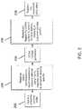
- Figure 2generally illustrates one example of an operation at the transmitting apparatus 110 to generate the synchronization signal S 1 with a given time domain repetition property N SF in accordance with the aspects of the disclosed embodiments.
- the processor 112is configured to derive 202 at least one subcarrier spacing value from the plurality of subcarrier spacing values that includes at least the first subcarrier spacing value ⁇ f 1 and at least the second subcarrier spacing value ⁇ f 2 .
- the transmitting apparatus 110may select, e.g. in a pre-determined way, or in a dynamic manner, or by any implementation, at least one value from a plurality of subcarrier spacing values supported in the wireless communication system 100.
- the subcarrier spacing valueis used to generate a symbol based on OFDM waveform, e.g. OFDM, DFT-s-OFDM, SC-FDMA or other OFDM variants.
- a synchronization signal sequenceis mapped 204 to a resource element (e.g. an element in the resource grid as defined in 3GPP TS36.211) using a 1-to-N 1 mapping, where N 1 is subcarrier spacing specific and a function of the derived subcarrier spacing value ⁇ f , ⁇ f 1 or ⁇ f 2 .
- N 1⁇ f / ⁇ f 1 . This generates N 1 repetitions in the time domain, as explained below with respect to Equations 4a and 4b.
- An OFDM symbolis generated 206.
- a symbol comprising the synchronization signal S 1is transmitted 210.
- the aspects of the disclosed embodimentsare directed to generating a common/same time domain synchronization signal S 1 based on a same synchronization sequence using different subcarrier spacing values.
- the term "common” as referred to herein with respect to the synchronization signal S 1generally means that the signal S 1 is the same regardless of the subcarrier frequency that is actually used.
- the LTE Orthogonal Frequency Division Multiple Access (OFDMA) waveformis considered using a 15 KHz subcarrier spacing, together with an LTE length-62 Primary Synchronization Signal (PSS) sequence. While 15 KHz and 30 KHz subcarrier spacing's are generally referred to herein, it shall be understood the aspects of the disclosed embodiments can be extended to any other suitable subcarrier spacing values and any other length synchronization signal sequences.
- OFDMAOrthogonal Frequency Division Multiple Access
- the aspects of the disclosed embodimentscan be applicable to an OFDM based waveform, which can be any variants of an OFDMA waveform, such as for example, but not limited to pre-coded Orthogonal Frequency Division Multiplexing (OFDM) waveforms and Single Carrier Frequency Division Multiple Access (SC-FDMA) waveforms.
- OFDMOrthogonal Frequency Division Multiplexing
- SC-FDMASingle Carrier Frequency Division Multiple Access
- the aspects of the disclosed embodimentscan also be implemented in downlink, uplink and sidelink communication schemes.
- the synchronization signal sequencecan be a downlink/sidelink synchronization sequence, or an uplink Physical Random Access Channel (PRACH) preamble sequence.
- PRACHPhysical Random Access Channel
- FIG. 3AOne example of frequency domain mapping for a NR carrier supporting multiple subcarrier spacing values is shown in Figures 3A and 3B .
- the DC subcarrieris not shown in Figure 3A and 3B .
- the subcarrier spacing valueis 15 KHz and the mapping represents a 1-to-2 resource element (RE) mapping.
- the subcarrier spacing valueis 30 KHz and represents a 1-to-1 RE mapping.
- a typical synchronization sequenceuses 62 subcarriers in total, with 31 subcarriers mapped on each side of the DC subcarrier, which is not used.
- the length-62 PSS sequencein order to generate a time repetition signal for a small subcarrier spacing value ⁇ f 1 , e.g. 15 KHz, the length-62 PSS sequence is mapped to every other resource element, where each resource element is referenced as d(0) to d(61).
- ⁇ f 1e.g. 15 KHz
- the length-62 PSS sequenceis mapped to every resource element, where each resource element is referenced as d(0) to d(61).
- T S21/ ⁇ f 2 corresponds to the OFDM symbol duration with subcarrier spacing of ⁇ f 2
- Nis an positive integer, e.g. the FFT size.
- the subcarrier spacing valueis 30 KHz.
- the length-62 PSS sequenceis mapped to every resource element d(0)-d(61).
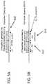
- the graph shown in Figure 4represents a time domain signal 400 that is the result of the mapping of a PSS sequence to every other resource element for 15 KHz subcarrier spacing and mapping a PSS sequence in a localized or contiguous manner for a 30 KHz subcarrier spacing.
- the portion 402 of the time domain signal 400represents the length 62-PSS mapped to every resource element (1:1 RE mapping) for a subcarrier spacing of 30 KHz.
- the portion 404 of the time domain signal 400represents the length-62 PSS mapped to every other resource element (1:2 RE mapping) for a subcarrier spacing of 15 KHz, which is a two time repetition of the mapping of the same length 62-PSS to every resource element for 30 KHz subcarrier spacing.
- the time domain signal of the portion 402 and the portion 404 of the time domain signal 400are substantially the same.
- Figures 5A and 5Billustrate exemplary time repetition properties of an OFDM symbol for a small subcarrier spacing and a large subcarrier spacing, respectively.
- the time repetition property resulting from a frequency domain 1-to-X mapping for a small subcarrier spacing value, ⁇ f 1 , which in this example is 15 KHz,is illustrated.
- the OFDM symbol 502 in Figure 5Ais preceded by the cyclic prefix (CP), and is generated by mapping a synchronization signal sequence to every other resource element for the subcarrier spacing of 15 KHz.
- Figure 5Aillustrates the 2-repetition property of the OFDM symbol 502.
- Figure 5Billustrates the time repetition operation for a large subcarrier spacing value, which in this example is 30 KHz.
- a time repetition signal for a large subcarrier spacing value ⁇ f 2e.g. 30 KHz
- the length-62 PSS sequenceis mapped in a localized way, i.e. to every resource element.
- the generated signalis further repeated in the time domain, as OFDM symbols 512, 514.
- the first OFDM symbol 512is generated by mapping a synchronization signal sequence to resource elements where the subcarrier spacing is 30 KHz.
- CPcyclic prefix
- the second OFDM symbol 514is an immediate repetition of the first OFDM symbol 512.
- the second OFDM symbol 514is followed by a cyclic extension (cyclic postfix).
- Figure 5Billustrates the two time repetition of the OFDM symbol in the time domain.
- the signal S 1being the two time repetition of the signal S 2 is a time continuous repetition.
- the wireless communication systemsupports a plurality of subcarrier spacing values of 15/30/60 KHz.
- the largest subcarrier spacing valueis taken as ⁇ f 2 (60 KHz), where one value, e.g. the smallest value, is selected as ⁇ f 1 (15 KHz).
- the repetition factor N SF4. This is advantageous as the same synchronization signal can be generated by mapping a frequency domain synchronization signal sequence to resource elements using more than 2 subcarrier spacing values.
- Figure 6generally illustrates an exemplary structure and processing of the synchronization signal S 1 that is received at the receiver apparatus 120. Since the synchronization signal S 1 is the same in terms of the frequency domain occupancy and the time domain, across different subcarrier spacing values, a common low pass filter 602 and a common baseband signal processor 604 can be used at the receiving apparatus 120 to process the received synchronization signal S 1 . In one embodiment, the filter 602 and baseband signal processor 604 shown in Figure 6 can be coupled to or be included in as part of the transceiver 122 and/or processor 124, or the combination thereof, of Figure 1 .
- the filter 602comprises a baseband filter having a pass band independent (i.e. common) of the subcarrier spacing used for the transmitted synchronization signal S 1 and is configured to filter the detected or received synchronization signal S 1 .
- the received synchronization signal S 1is processed by the common baseband signal processor 604.
- the processor 604can comprise or include a matched filter where the received samples of the transmitted synchronization signal S 1 are multiplied with a replica of the transmitted signal.
- the time domain repetition factoris independent (i.e. common) of the subcarrier spacing used for the transmitted synchronization signal S 1 .
- baseband signal processor 604is typically done in the time domain based on correlation.
- One typical implementationis a matched filter where the received samples are multiplied with a replica of the transmitted signal.
- a typical synchronization signal S 1is designed with good correlation properties.
- the correlation valueis significantly lower.
- the matched filtershall take into account the correlation values at least in a window not less than ( N 1 - 1 ) T S2 , where T S2 is the symbol duration corresponding to subcarrier spacing of ⁇ f 2 .
- T S2is the symbol duration corresponding to subcarrier spacing of ⁇ f 2 .
- the matched filterselects the largest value within this window as the main peak, and the corresponding timing as the timing information.
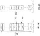
- the OFDM waveform with Direct Current (DC) subcarrier not mappedreference 302 illustrates the mapping characterized by 2(N 1 - 1) resource element(s) not mapped between only one pair of two adjacent PSS-mapping resource elements d(30) and d(31).
- Reference 304illustrate the mapping characterized by N 1 - 1 resource element(s) not mapped between other pairs of two adjacent PSS-mapping resource element, such as d(29) and d(30). This is further illustrated in Figure 8 .
- Lis the synchronization signal sequence length
- ⁇is a positive integer
- N 1is a positive integer, which is derived from ⁇ f 2 and ⁇ f 1 .
- the repeated OFDM symbolis different from a normal OFDM symbol, as the repeated OFDM symbol starts with the useful OFDM symbol part rather than a Cyclic Prefix (CP). This ensures that the time domain signal generated for different subcarrier spacings is the same.
- CPCyclic Prefix
- FIG. 9An example of this is shown in Figure 9 .
- the OFDM symbol 902is repeated as OFDM symbol 912.
- the signal S 1being the 2 time repetition of the signal S 2 is a time continuous repetition.
- the signal between the end of useful OFDM symbol 912 and the start of the next OFDM symbolcan be generated using a cyclic extension 914 (or cyclic postfix) of the useful OFDM symbol 912 to avoid inter-carrier interference (ICI).
- ICIinter-carrier interference
- the useful information part in the OFDM symbol of the repeated OFDM symbolis different with normal OFDM symbols (starting with CP 904 and followed by the useful OFDM symbol 902).
- Different useful OFDM symbol positionsenable the receiving apparatus 120 to detect the subcarrier spacing.
- the repeated OFDM symbolcan be manipulated in a pre-configured way. This can be understood as that the subcarrier spacing information is encoded by the repetition. Any form of a synchronization signal generated from the previous OFDM symbol for synchronization signal can be regarded as "repeated".
- the repeated OFDM symbol 912is generated using the first symbol 902 multiplied by a specific value known by both the transmitting apparatus 110 and receiving apparatus 120, e.g. -1, as illustrated in Figure 9 .
- Different time domain repetition for different subcarrier spacing valuesenables the receiving apparatus 120 to detect the subcarrier spacing.
- the signal S 1 being the N SF time repetition of the signal S 2is a time discontinuous repetition, e.g. there is a cyclic prefix between the signal S 2 and a repetition of the signal S 2 .
- This means the cyclic prefixis also repeated, which produces a different property in terms of the useful OFDM symbol time positions for the signal S 1 across different subcarrier spacing values. This is advantageous as the subcarrier spacing values can be detectable.
- the carrieris divided into several subbands, where each subband corresponds to a subband specific subcarrier spacing value to which a synchronization signal sequence is mapped.
- a subband specific synchronizationallows the receiving apparatus 120 to access the channel on a subband basis, which may further simplify the operation of the receiving apparatus 120. For example in this case, the receiving apparatus 120 can operate with the specific subband bandwidth instead of the entire downlink bandwidth.
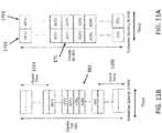
- Figure 10illustrates one example of frequency domain mapping for different subcarrier spacing values.
- a same length-L synchronization signal sequence 141is mapped 140 to every resource element d(0)-d(61) in a localized way, and repeats 150 in the time domain for N SF times.
- a length-L synchronization signal sequence 161is mapped 160 to every other RE.
- ⁇ f 1e.g. 15 KHz
- a length-L synchronization signal sequence 161is mapped 160 to every other RE.
- the corresponding time domain repetition propertyreferring to equations 4a and 4b above, is applicable.
- the subcarrier spacingis specific to the synchronization signal S 1 .
- the synchronization signal S 1is the same in terms of the frequency domain occupancy and the time domain occupancy. However, the time domain signal is different across different subcarrier spacing values.
- Figure 11Aillustrates a large subcarrier spacing value ⁇ f 2 , e.g. 30 KHz, where the same length-L synchronization signal sequence 171 is mapped to every RE d(0) - d(61) in a localized way.
- the resulting synchronization signal 1701also repeats 1702 in the time domain for N SF times.
- a length-L synchronization signal sequence 181is mapped to every RE d(0) - d(61) in a localized way.
- guard tones 1102, 1104are added before and after the length-L synchronization signal sequence 181.
- the number of REs for the guard tones 1102, 1104is at least (N SF - 1)L.
- the frequency domain and the time domain occupancyis the same for both subcarrier spacing values ⁇ f 1 , and ⁇ f 2 .
- the time domain synchronization signal S 1is two repetitions of a basic waveform S 2
- the time domain synchronization signal S 1is generally not a repetition of a basic waveform S 2 . Therefore the time domain waveform is subcarrier spacing specific, while the time domain repetition property holds at least for the carrier or subband corresponding to one subcarrier spacing value, e.g. 30 KHz.
- a common low pass filtersuch as filter 602 of Figure 6
- filter 602 of Figure 6can be used to detect the synchronization signal S 1 .
- the same length time signalcan be used for different subcarrier spacing values, which simplifies the receiver implementation.
- the time domain signalis different for two cases, which allows the receiving apparatus 120 to detect the subcarrier spacing using the time domain signal.
- Thisalso allows an LTE UE to properly detect the synchronization signal when the eNodeB is transmitting using LTE subcarrier spacing, e.g. 15 KHz.
- the UEmay use a LTE-compatible low pass filter.
- FIG. 12illustrates a block diagram of an exemplary transceiver apparatus 1000 appropriate for implementing aspects of the disclosed embodiments.
- the transceiver apparatus 1000is appropriate for use in a wireless network and can be implemented in one or more of the transmitting apparatus 110 or receiving apparatus 120, such as for the transceiver 114 and/or transceiver 122.
- the transceiver apparatuscan be implement in one or more of a network node or a user node, where user node can include various types of mobile computing devices, including various types of wireless communications user equipment such as cell phones, smart phones, tablet devices, and wirelessly connected automobiles.
- the transceiver apparatus 1000may be configured in or as an access node or base station in a wireless communication network.
- the transceiver apparatus 1000includes or is coupled to a processor or computing hardware 1002, a memory 1004, a radio frequency (RF) unit 1006 and a user interface (UI) 1008.
- a processor or computing hardware 1002includes or is coupled to a processor or computing hardware 1002, a memory 1004, a radio frequency (RF) unit 1006 and a user interface (UI) 1008.
- RFradio frequency
- UIuser interface
- the UI 1008may be removed from the transceiver apparatus 1000.
- the transceiver apparatus 1000may be administered remotely or locally through a wireless or wired network connection (not shown).
- the processor 1002may be a single processing device or may comprise a plurality of processing devices including special purpose devices, such as for example, digital signal processing (DSP) devices, microprocessors, graphics processing units (GPU), specialized processing devices, or general purpose computer processing unit (CPU).
- DSPdigital signal processing
- GPUgraphics processing units
- CPUgeneral purpose computer processing unit
- the processor 1002often includes a CPU working in tandem with a DSP to handle signal processing tasks.
- the processor 1002which can be implemented as one or more of the processors 112 and 124 described with respect to Figure 1 , may be configured to implement any of the methods described herein.
- the processor 1002is configured to be coupled to a memory 1004 which may be a combination of various types of volatile and non-volatile computer memory such as for example read only memory (ROM), random access memory (RAM), magnetic or optical disk, or other types of computer memory.
- the memory 1004is configured to store computer program instructions that may be accessed and executed by the processor 1002 to cause the processor 1002 to perform a variety of desirable computer implemented processes or methods such as the methods as described herein.
- the program instructions stored in memory 1004are organized as sets or groups of program instructions referred to in the industry with various terms such as programs, software components, software modules, units, etc. Each module may include a set of functionality designed to support a certain purpose. For example a software module may be of a recognized type such as a hypervisor, a virtual execution environment, an operating system, an application, a device driver, or other conventionally recognized type of software component. Also included in the memory 1004 are program data and data files which may be stored and processed by the processor 1002 while executing a set of computer program instructions.
- the transceiver 1000can also include an RF Unit 1006 coupled to the processor 1002 that is configured to transmit and receive RF signals based on digital data 1012 exchanged with the processor 1002 and may be configured to transmit and receive radio signals with other nodes in a wireless network.
- the RF Unit 1006includes receivers capable of receiving and interpreting messages sent from satellites in the global positioning system (GPS) and work together with information received from other transmitters to obtain positioning information pertaining to the location of the computing device 1000.
- GPSglobal positioning system
- the RF unit 1006includes an antenna unit 1010 which in certain embodiments may include a plurality of antenna elements.
- the multiple antennas 1010may be configured to support transmitting and receiving MIMO signals as may be used for beamforming.
- the antenna unit 1010 of Figure 10can be implemented as one or more of the antenna unit 102 or the antenna unit 106 shown in Figure 1 .
- the UI 1008may include one or more user interface elements such as a touch screen, keypad, buttons, voice command processor, as well as other elements adapted for exchanging information with a user.
- the UI 1008may also include a display unit configured to display a variety of information appropriate for a computing device or mobile user equipment and may be implemented using any appropriate display type such as for example organic light emitting diodes (OLED), liquid crystal display (LCD), as well as less complex elements such as LEDs or indicator lamps.
- OLEDorganic light emitting diodes
- LCDliquid crystal display
- the aspects of the disclosed embodimentsare directed to providing a synchronization signal which can be transmitted on a carrier, such as a new radio carrier, where the carrier is capable of multiple subcarrier spacing values.
- the synchronization signal generation method generally described hereinadvantageously provide for the same bandwidth for a synchronization signal for different subcarrier spacing values, which allows the detector to use one unified low pass filter.
- the synchronization signal generation method described hereinprovides the same synchronization signal sequence for different subcarrier spacing values, which simplifies both the detector and the transmitter.
- the synchronization signal generation method described hereinprovides the same synchronization signal in the time domain for different subcarrier spacing values, which allows the detector to share the same matched filter and therefore reduces the receiver complexity.
- the synchronization signal generation method described hereinalso provides the same subcarrier spacing for the synchronization signal and the other physical channels/signals multiplexed in the same carrier or the same subband, which avoids ICI and simplifies the transmitter implementation.
Landscapes
- Engineering & Computer Science (AREA)
- Computer Networks & Wireless Communication (AREA)
- Signal Processing (AREA)
- Physics & Mathematics (AREA)
- Mathematical Physics (AREA)
- Mobile Radio Communication Systems (AREA)
Description
- The aspects of the present disclosure relate generally to wireless communication systems and more particularly to new radio (NR) access technology wireless communication systems.
- A fundamental procedure in a cellular wireless communication system is synchronization. Synchronization is performed by a mobile terminal for obtaining time and frequency synchronization to a cell in the network and detecting its cell identity. In Long Term Evolution (LTE), the synchronization signal is always transmitted in a carrier with fixed subcarrier spacing. This fixed carrier spacing, i.e. 15 KHz, is known by both the user equipment (UE) and the network or transmitting node prior to the synchronization procedure.
- The 3rd Generation Partnership Project (3GPP) is currently working on a New Radio (NR) access technology. To address various scenarios and requirements, NR may support multiple numerologies via scalable numerology or mixed numerology using Orthogonal Frequency Division Multiplexing (OFDM) based waveforms. An OFDM based waveform could be OFDM, or precoded OFDM like Discrete Fourier Transform-spread-OFDM ((DFT-s-OFDM), or Single Carrier Frequency Division Multiple Access (SC-FDMA), or any other OFDM variants based on OFDM.
- One major change of NR to LTE in terms of synchronization is that the carrier or sub-band containing the synchronization signal is not always a fixed spacing value. The actually used subcarrier spacing at the network side may not be known by the UE prior to the synchronization procedure. It is therefore an issue to provide a synchronization signal which can be transmitted on a NR carrier capable of multiple subcarrier spacing values, while providing efficient and low-complexity UE synchronization operation.
- Accordingly, it would be desirable to be able to provide a synchronization signal transceiving scheme for initial access in a new radio cellular system in a manner that addresses at least some of the problems identified above.
US 2008/0205351 relates to subcarrier spacing identification.US 2015/0055616 relates to transmission method and transmission device.- It is an object of the invention to provide an efficient synchronization signal transceiving scheme for initial access in a new radio type cellular communication system using an OFDM based waveform. This object is solved by the subject matter of the independent claims. Further advantageous modifications can be found in the dependent claims.
- These and other aspects, implementation forms, and advantages of the exemplary embodiments will become apparent from the embodiments described herein considered in conjunction with the accompanying drawings. It is to be understood, however, that the description and drawings are designed solely for purposes of illustration and not as a definition of the limits of the disclosed invention, for which reference should be made to the appended claims. Additional aspects and advantages of the invention will be set forth in the description that follows, and in part will be obvious from the description, or may be learned by practice of the invention. Moreover, the aspects and advantages of the invention may be realized and obtained by means of the instrumentalities and combinations particularly pointed out in the appended claims.
- In the following detailed portion of the present disclosure, the invention will be explained in more detail with reference to the example embodiments shown in the drawings, in which:
Figure 1 is a block diagram illustrating an exemplary wireless communication system incorporating aspects of the disclosed embodiments.Figure 2 illustrates a block diagram of an exemplary process flow in a transmitter apparatus incorporating aspects of the disclosed embodiments.Figures 3A and 3B illustrate schematic diagrams of exemplary frequency domain mapping for different subcarrier spacing values in a system incorporating aspects of the disclosed embodiments.Figure 4 illustrates a graph of exemplary time domain signal mapping in a system incorporating aspects of the disclosed embodiments.Figure 5 illustrates exemplary time repetition properties of an OFDM symbol in a system incorporating aspects of the disclosed embodiments.Figure 6 illustrates a block diagram of an exemplary receiver structure for a system incorporating aspects of the disclosed embodiments.Figure 7 illustrates exemplary timing information for correlation values in a correlation window of a system incorporating aspects of the disclosed embodiments.Figure 8 illustrates an exemplary primary synchronization signal mapping in a system incorporating aspects of the disclosed embodiments.Figure 9 illustrates an exemplary timing repetition operation of an OFDM symbol in a system incorporating aspects of the disclosed embodiments.Figure 10 illustrates an exemplary frequency domain mapping for different subcarrier spacing values in a system incorporating aspects of the disclosed embodiments.Figures 11A and 11B illustrate exemplary frequency domain mapping for different subcarrier spacing values in a system incorporating aspects of the disclosed embodiments.Figure 12 illustrates a schematic block diagram of an apparatus architecture that can be used to practice aspects of the disclosed embodiments.- Referring to
Figure 1 there can be seen an exemplary block diagram ofwireless communication system 100 incorporating aspects of the disclosed embodiments. The aspects of the disclosed embodiments are directed to providing a synchronization signal transceiving scheme for initial access in a new radio cellular system capable of multiple subcarrier spacing values. The common synchronization signal S1 has the same bandwidth occupancy and time occupancy for a same length synchronization signal sequence for a carrier operating with different subcarrier spacing values, where the different subcarrier spacing values include at least a first or small subcarrier spacing value Δf1 and a second or large subcarrier spacing value Δf2. - As is illustrated in
Figure 1 , thewireless communication system 100 includes at least one transmittingapparatus 110 and at least onereceiver apparatus 120. Thewireless communication system 100 can be any suitable type of wireless communication system, such as for example, LTE, 5G or NR In one embodiment, the transmittingapparatus 110 can comprise or include a network node such as an Evolved Universal Terrestrial Radio Access Network (E-UTRAN) NodeB or evolved NodeB (eNB), or a user node or equipment (UE) such as a mobile communication device. Thereceiving apparatus 120 can comprise or include a user node or equipment (UE) such as a mobile communication device, or a network node such as an (E-UTRAN) NodeB or evolved NodeB (eNB), or UE such as a mobile communication device, for example. - In the example of
Figure 1 , thetransmitting apparatus 110 includes at least oneprocessor 112 and at least one transmitter ortransceiver device 114. While theprocessor 112 andtransceiver 114 are shown inFigure 1 as being separate devices, in alternate embodiments, theprocessor 112 andtransceiver device 114 can comprises a single device. The transmittingapparatus 110 can include any suitable number ofprocessors 112 andtransceivers 114, depending upon the particular application and implementation. - The transmitting
apparatus 110 can also include one or more antennas orantenna arrays 102. The antennas orantenna arrays 102 will be generally configured to generate one or more directional beams, generally referred to herein asdirectional beams 104. - The receiver or receiving
apparatus 120 generally includes a receiver ortransceiver 122 and aprocessor 124. Although thetransceiver 122 andprocessor 124 are shown in the example ofFigure 1 as separate devices, in alternate embodiments, thetransceiver 122 andprocessor 124 can comprise a single device or unit. - The
receiving apparatus 120 will also include one or more antennas orantenna arrays 106. Theantennas 106 are configured to generate one or morereceiving beam patterns 108, to receive, among other things, the signals transmitted from the transmittingapparatus 110. - The
wireless communication system 100 includes an OFDM based waveform corresponding to a plurality of pre-defined subcarrier spacing values comprising at least a first subcarrier spacing value Δf1 and at least a second subcarrier spacing value Δf2. An OFDM waveform comprises a plurality of subcarriers. Any value of the plurality of pre-defined subcarrier values is supported or can be used in the wireless communication system (100). The term "corresponding to" as used herein generally means that any value of a plurality of pre-defined subcarrier spacing values is supported or can be used in the wireless communication system. The first subcarrier spacing value Δf1 can be referred to as a small or basic subcarrier spacing value. The second subcarrier spacing value Δf2 can referred to as a large or scaled subcarrier spacing value. - The
processor 112 is configured to generate a synchronization signal S1 that has a NSF time repetition property of another signal S2. In one embodiment, the synchronization signal S1 is the same in terms of the frequency domain occupancy and the time domain signal as is further described below with respect to equation 4a and 4b. The signal S2 has a duration of 1/ Δf2. The time domain waveform of the synchronization signal S1 is a NSF = Δf2 / Δf1, repetition of a basic waveform S2, referred to herein as the another signal S2, where NSF is an integer greater than 1. - The
processor 112 is configured to generate an OFDM symbol comprising the synchronization signal S1. Thetransmitter 114 is configured to transmit the OFDM symbol comprising S1. Figure 2 generally illustrates one example of an operation at the transmittingapparatus 110 to generate the synchronization signal S1 with a given time domain repetition property NSF in accordance with the aspects of the disclosed embodiments. In one embodiment, theprocessor 112 is configured to derive 202 at least one subcarrier spacing value from the plurality of subcarrier spacing values that includes at least the first subcarrier spacing value Δf1 and at least the second subcarrier spacing value Δf2. For example, the transmittingapparatus 110 may select, e.g. in a pre-determined way, or in a dynamic manner, or by any implementation, at least one value from a plurality of subcarrier spacing values supported in thewireless communication system 100. The subcarrier spacing value is used to generate a symbol based on OFDM waveform, e.g. OFDM, DFT-s-OFDM, SC-FDMA or other OFDM variants. A synchronization signal sequence is mapped 204 to a resource element (e.g. an element in the resource grid as defined in 3GPP TS36.211) using a 1-to-N1 mapping, where N1 is subcarrier spacing specific and a function of the derived subcarrier spacing value Δf, Δf1 or Δf2. In one example, N1 = Δf/Δf1. This generates N1 repetitions in the time domain, as explained below with respect to Equations 4a and 4b.- An OFDM symbol is generated 206. The OFDM symbol is repeated 208, N2 times in the time domain, where N2 is subcarrier spacing specific and N1 × N2 = NSF.. This in total generates NSF repetitions of the another signal S2 in the time domain. It should be noted that the repetition step is not always needed, because repetition can be understood as not performed when N2 = 1. A symbol comprising the synchronization signal S1 is transmitted 210.
- The aspects of the disclosed embodiments are directed to generating a common/same time domain synchronization signal S1 based on a same synchronization sequence using different subcarrier spacing values. The term "common" as referred to herein with respect to the synchronization signal S1 generally means that the signal S1 is the same regardless of the subcarrier frequency that is actually used.
- In the following description, the LTE Orthogonal Frequency Division Multiple Access (OFDMA) waveform is considered using a 15 KHz subcarrier spacing, together with an LTE length-62 Primary Synchronization Signal (PSS) sequence. While 15 KHz and 30 KHz subcarrier spacing's are generally referred to herein, it shall be understood the aspects of the disclosed embodiments can be extended to any other suitable subcarrier spacing values and any other length synchronization signal sequences. The aspects of the disclosed embodiments can be applicable to an OFDM based waveform, which can be any variants of an OFDMA waveform, such as for example, but not limited to pre-coded Orthogonal Frequency Division Multiplexing (OFDM) waveforms and Single Carrier Frequency Division Multiple Access (SC-FDMA) waveforms. The aspects of the disclosed embodiments can also be implemented in downlink, uplink and sidelink communication schemes. For example, the synchronization signal sequence can be a downlink/sidelink synchronization sequence, or an uplink Physical Random Access Channel (PRACH) preamble sequence.
- The OFDM waveform without a cyclic prefix can be defined by:


- The sampled version by settingt =n/fs is:

for n = 0,1, ..., N - 1 where H[k] is a Fourier coefficient at frequency k. - The LTE PSS sequence is given by:

where u is the Zadoff-Chu root sequence index. - The mapping for Frequency Division Duplexing (FDD) (Frame Structure 1) is as specified in 3GPP TS36.211:
ak =d(m), m = 0,...,61
- The sampled signal is:

- One example of frequency domain mapping for a NR carrier supporting multiple subcarrier spacing values is shown in
Figures 3A and 3B . The DC subcarrier is not shown inFigure 3A and 3B . In the example ofFigure 3A , the subcarrier spacing value is 15 KHz and the mapping represents a 1-to-2 resource element (RE) mapping. In the example ofFigure 3B , the subcarrier spacing value is 30 KHz and represents a 1-to-1 RE mapping. - A typical synchronization sequence uses 62 subcarriers in total, with 31 subcarriers mapped on each side of the DC subcarrier, which is not used. In the example of
Figure 3A , in order to generate a time repetition signal for a small subcarrier spacing value Δf1 , e.g. 15 KHz, the length-62 PSS sequence is mapped to every other resource element, where each resource element is referenced as d(0) to d(61). In the example ofFigure 3B , for a large subcarrier spacing value Δf2, e.g. 30 KHz, the length-62 PSS sequence is mapped to every resource element, where each resource element is referenced as d(0) to d(61). - The 1-to-2 RE mapping of the length-62 PSS sequence illustrated in the example of
Figure 3A is given by:
ak =d(m),m = 0,...,61
- The sampled version is therefore given by:

- It can be further shown that:

- The above demonstrates that for a subcarrier spacing of 15 KHz, for a length-62 PSS sequence, there is a two time repetition by a 1-to-2 mapping, i.e. by mapping the length-62 PSS sequence to every other resource element, or 1 resource element in every 2 resource elements, as is shown in
Figure 3A . Similar observations hold for 1 to X mapping, i.e. there are X time repetitions in time domain. The time repetition factor X is given by NSF = Δf2 / Δf1. The NSF time repetition waveform satisfies at least one of the following in the discrete form and the continuous form:

where TS2 = 1/ Δf2 corresponds to the OFDM symbol duration with subcarrier spacing of Δf2, N is an positive integer, e.g. the FFT size. - In the example of
Figure 3B , the subcarrier spacing value is 30 KHz. For a large subcarrier spacing value, e.g. 30 KHz, the length-62 PSS sequence is mapped to every resource element d(0)-d(61). The resulting signal is given by:
- The above demonstrates that the resulting signal from equation (5) is the same as the signal from equation (3) without considering the normalization value, where the difference is that the signal from equation (3) is a two time repetition of the signal from equation (5). This is further illustrated by the graph in
Figure 4 . - The graph shown in
Figure 4 represents atime domain signal 400 that is the result of the mapping of a PSS sequence to every other resource element for 15 KHz subcarrier spacing and mapping a PSS sequence in a localized or contiguous manner for a 30 KHz subcarrier spacing. Theportion 402 of thetime domain signal 400 represents the length 62-PSS mapped to every resource element (1:1 RE mapping) for a subcarrier spacing of 30 KHz. Theportion 404 of thetime domain signal 400 represents the length-62 PSS mapped to every other resource element (1:2 RE mapping) for a subcarrier spacing of 15 KHz, which is a two time repetition of the mapping of the same length 62-PSS to every resource element for 30 KHz subcarrier spacing. As is illustrated in the example ofFigure 4 , the time domain signal of theportion 402 and theportion 404 of thetime domain signal 400 are substantially the same. Figures 5A and 5B illustrate exemplary time repetition properties of an OFDM symbol for a small subcarrier spacing and a large subcarrier spacing, respectively. InFigure 5A the time repetition property resulting from a frequency domain 1-to-X mapping for a small subcarrier spacing value, Δf1, which in this example is 15 KHz, is illustrated. TheOFDM symbol 502 inFigure 5A is preceded by the cyclic prefix (CP), and is generated by mapping a synchronization signal sequence to every other resource element for the subcarrier spacing of 15 KHz.Figure 5A illustrates the 2-repetition property of theOFDM symbol 502.Figure 5B illustrates the time repetition operation for a large subcarrier spacing value, which in this example is 30 KHz. To generate a time repetition signal for a large subcarrier spacing value Δf2, e.g. 30 KHz, the length-62 PSS sequence is mapped in a localized way, i.e. to every resource element. The generated signal is further repeated in the time domain, asOFDM symbols first OFDM symbol 512 is generated by mapping a synchronization signal sequence to resource elements where the subcarrier spacing is 30 KHz. A cyclic prefix (CP) precedes thefirst OFDM symbol 512.- The
second OFDM symbol 514 is an immediate repetition of thefirst OFDM symbol 512. Thesecond OFDM symbol 514 is followed by a cyclic extension (cyclic postfix).Figure 5B illustrates the two time repetition of the OFDM symbol in the time domain. The signal S1 being the two time repetition of the signal S2 is a time continuous repetition. - In one example, the wireless communication system supports a plurality of subcarrier spacing values of 15/30/60 KHz. The largest subcarrier spacing value is taken as Δf2 (60 KHz), where one value, e.g. the smallest value, is selected as Δf1 (15 KHz). In this example the repetition factor NSF = 4. This is advantageous as the same synchronization signal can be generated by mapping a frequency domain synchronization signal sequence to resource elements using more than 2 subcarrier spacing values.
Figure 6 generally illustrates an exemplary structure and processing of the synchronization signal S1 that is received at thereceiver apparatus 120. Since the synchronization signal S1 is the same in terms of the frequency domain occupancy and the time domain, across different subcarrier spacing values, a commonlow pass filter 602 and a commonbaseband signal processor 604 can be used at the receivingapparatus 120 to process the received synchronization signal S1. In one embodiment, thefilter 602 andbaseband signal processor 604 shown inFigure 6 can be coupled to or be included in as part of thetransceiver 122 and/orprocessor 124, or the combination thereof, ofFigure 1 .- In one embodiment, the
filter 602 comprises a baseband filter having a pass band independent (i.e. common) of the subcarrier spacing used for the transmitted synchronization signal S1 and is configured to filter the detected or received synchronization signal S1. After processing by thelow pass filter 602, the received synchronization signal S1 is processed by the commonbaseband signal processor 604. Theprocessor 604 can comprise or include a matched filter where the received samples of the transmitted synchronization signal S1 are multiplied with a replica of the transmitted signal. The time domain repetition factor is independent (i.e. common) of the subcarrier spacing used for the transmitted synchronization signal S1. - The processing by
baseband signal processor 604 is typically done in the time domain based on correlation. One typical implementation is a matched filter where the received samples are multiplied with a replica of the transmitted signal. - A typical synchronization signal S1 is designed with good correlation properties. When the received samplesr[n] are multiplied with a replica of the transmitted signal, a correlation peak is created at the correct timing:

- With the time repetition synchronization waveform, the correlation property with only one peak does not hold. There is one main peakP0 at the correct timing, i.e. the received signal waveform completely overlaps with the replica of the transmitted signal. In the meantime, there are2(N1 -1) side peaks at the timing that are partially overlapping. An example of this is illustrated in
Figure 7 . - To avoid detecting the side peaks as the main peak, the matched filter shall take into account the correlation values at least in a window not less than (N1 -1)TS2, whereTS2 is the symbol duration corresponding to subcarrier spacing of Δf2. The matched filter selects the largest value within this window as the main peak, and the corresponding timing as the timing information.
- Referring again to
Figure 3A and also Equation (1), it can be observed that the 1-to-N1 mapping is not exactly evenly distributed in the frequency domain. For the specific example ofFigure 3A , the OFDM waveform with Direct Current (DC) subcarrier not mapped,reference 302 illustrates the mapping characterized by 2(N1 - 1) resource element(s) not mapped between only one pair of two adjacent PSS-mapping resource elements d(30) and d(31).Reference 304 illustrate the mapping characterized by N1 - 1 resource element(s) not mapped between other pairs of two adjacent PSS-mapping resource element, such as d(29) and d(30). This is further illustrated inFigure 8 . InFigure 8 there are two empty resource elements in thegap 802 between the central two adjacent resource elements, PSS(b) and PSS(C) while there is one empty resource element in thegap 804 between other adjacent resource elements, such as PSS(a) and PSS(b) or PSS(c) and PSS(d). - The mapping is further generalized by:

whereL is the synchronization signal sequence length, and Δ is a positive integer, N1 is a positive integer, which is derived from Δf2and Δf1. - For time domain repetition, the repeated OFDM symbol is different from a normal OFDM symbol, as the repeated OFDM symbol starts with the useful OFDM symbol part rather than a Cyclic Prefix (CP). This ensures that the time domain signal generated for different subcarrier spacings is the same. An example of this is shown in
Figure 9 . In this example, theOFDM symbol 902 is repeated asOFDM symbol 912. The signal S1 being the 2 time repetition of the signal S2 is a time continuous repetition. - The signal between the end of
useful OFDM symbol 912 and the start of the next OFDM symbol can be generated using a cyclic extension 914 (or cyclic postfix) of theuseful OFDM symbol 912 to avoid inter-carrier interference (ICI). In addition, the useful information part in the OFDM symbol of the repeated OFDM symbol (starting with theuseful OFDM symbol 912 and followed by the cyclic extension/cyclic postfix 914) is different with normal OFDM symbols (starting withCP 904 and followed by the useful OFDM symbol 902). Different useful OFDM symbol positions enable the receivingapparatus 120 to detect the subcarrier spacing. - For time domain repetition, the repeated OFDM symbol can be manipulated in a pre-configured way. This can be understood as that the subcarrier spacing information is encoded by the repetition. Any form of a synchronization signal generated from the previous OFDM symbol for synchronization signal can be regarded as "repeated". One example is that the repeated
OFDM symbol 912 is generated using thefirst symbol 902 multiplied by a specific value known by both the transmittingapparatus 110 and receivingapparatus 120, e.g. -1, as illustrated inFigure 9 . Different time domain repetition for different subcarrier spacing values enables the receivingapparatus 120 to detect the subcarrier spacing. - In one example, for the OFDM based waveform using the subcarrier spacing Δf2, the signal S1 being the NSF time repetition of the signal S2 is a time discontinuous repetition, e.g. there is a cyclic prefix between the signal S2 and a repetition of the signal S2. This means the cyclic prefix is also repeated, which produces a different property in terms of the useful OFDM symbol time positions for the signal S1 across different subcarrier spacing values. This is advantageous as the subcarrier spacing values can be detectable.
- In one embodiment, the carrier is divided into several subbands, where each subband corresponds to a subband specific subcarrier spacing value to which a synchronization signal sequence is mapped. A subband specific synchronization allows the receiving
apparatus 120 to access the channel on a subband basis, which may further simplify the operation of the receivingapparatus 120. For example in this case, the receivingapparatus 120 can operate with the specific subband bandwidth instead of the entire downlink bandwidth. - An example of this is shown in
Figure 10 , which illustrates one example of frequency domain mapping for different subcarrier spacing values. In this example, for a subband M with a larger subcarrier spacing Δf2, e.g. 30 KHz, a same length-Lsynchronization signal sequence 141 is mapped 140 to every resource element d(0)-d(61) in a localized way, and repeats 150 in the time domain for NSF times. - For the
subband 1 shown in the top portion ofFigure 10 , with a small subcarrier spacing value Δf1, e.g. 15 KHz, a length-Lsynchronization signal sequence 161 is mapped 160 to every other RE. For each synchronization sequence, the corresponding time domain repetition property, referring to equations 4a and 4b above, is applicable. - Referring to
Figures 11A and 11B , in one embodiment, the subcarrier spacing is specific to the synchronization signal S1. In this embodiment, the synchronization signal S1 is the same in terms of the frequency domain occupancy and the time domain occupancy. However, the time domain signal is different across different subcarrier spacing values. Figure 11A illustrates a large subcarrier spacing value Δf2, e.g. 30 KHz, where the same length-Lsynchronization signal sequence 171 is mapped to every RE d(0) - d(61) in a localized way. The resultingsynchronization signal 1701 also repeats 1702 in the time domain for NSF times.- Referring to
Figure 11B , for a small subcarrier spacing value Δf1, e.g. 15 KHz, a length-Lsynchronization signal sequence 181 is mapped to every RE d(0) - d(61) in a localized way. To ensure the same bandwidth occupancy as the case for the larger subcarrier spacing Δf2,guard tones synchronization signal sequence 181. The number of REs for theguard tones - In the example of
Figures 11A and 11B , the frequency domain and the time domain occupancy is the same for both subcarrier spacing values Δf1, and Δf2. For subcarrier spacing Δf2 of 30 KHz, the time domain synchronization signal S1 is two repetitions of a basic waveform S2, while for subcarrier spacing Δf1 of 15 KHz, the time domain synchronization signal S1 is generally not a repetition of a basic waveform S2. Therefore the time domain waveform is subcarrier spacing specific, while the time domain repetition property holds at least for the carrier or subband corresponding to one subcarrier spacing value, e.g. 30 KHz. - At the receiving apparatus 120 a common low pass filter, such as
filter 602 ofFigure 6 , can be used to detect the synchronization signal S1. The same length time signal can be used for different subcarrier spacing values, which simplifies the receiver implementation. The time domain signal is different for two cases, which allows the receivingapparatus 120 to detect the subcarrier spacing using the time domain signal. This also allows an LTE UE to properly detect the synchronization signal when the eNodeB is transmitting using LTE subcarrier spacing, e.g. 15 KHz. The UE may use a LTE-compatible low pass filter. Figure 12 illustrates a block diagram of anexemplary transceiver apparatus 1000 appropriate for implementing aspects of the disclosed embodiments. Thetransceiver apparatus 1000 is appropriate for use in a wireless network and can be implemented in one or more of the transmittingapparatus 110 or receivingapparatus 120, such as for thetransceiver 114 and/ortransceiver 122. The transceiver apparatus can be implement in one or more of a network node or a user node, where user node can include various types of mobile computing devices, including various types of wireless communications user equipment such as cell phones, smart phones, tablet devices, and wirelessly connected automobiles. Alternatively thetransceiver apparatus 1000 may be configured in or as an access node or base station in a wireless communication network.- The
transceiver apparatus 1000 includes or is coupled to a processor orcomputing hardware 1002, amemory 1004, a radio frequency (RF)unit 1006 and a user interface (UI) 1008. In certain embodiments such as for an access node or base station, theUI 1008 may be removed from thetransceiver apparatus 1000. When theUI 1008 is removed thetransceiver apparatus 1000 may be administered remotely or locally through a wireless or wired network connection (not shown). - The
processor 1002 may be a single processing device or may comprise a plurality of processing devices including special purpose devices, such as for example, digital signal processing (DSP) devices, microprocessors, graphics processing units (GPU), specialized processing devices, or general purpose computer processing unit (CPU). Theprocessor 1002 often includes a CPU working in tandem with a DSP to handle signal processing tasks. Theprocessor 1002, which can be implemented as one or more of theprocessors Figure 1 , may be configured to implement any of the methods described herein. - In the example of
Figure 12 , theprocessor 1002 is configured to be coupled to amemory 1004 which may be a combination of various types of volatile and non-volatile computer memory such as for example read only memory (ROM), random access memory (RAM), magnetic or optical disk, or other types of computer memory. Thememory 1004 is configured to store computer program instructions that may be accessed and executed by theprocessor 1002 to cause theprocessor 1002 to perform a variety of desirable computer implemented processes or methods such as the methods as described herein. - The program instructions stored in
memory 1004 are organized as sets or groups of program instructions referred to in the industry with various terms such as programs, software components, software modules, units, etc. Each module may include a set of functionality designed to support a certain purpose. For example a software module may be of a recognized type such as a hypervisor, a virtual execution environment, an operating system, an application, a device driver, or other conventionally recognized type of software component. Also included in thememory 1004 are program data and data files which may be stored and processed by theprocessor 1002 while executing a set of computer program instructions. - The
transceiver 1000 can also include anRF Unit 1006 coupled to theprocessor 1002 that is configured to transmit and receive RF signals based ondigital data 1012 exchanged with theprocessor 1002 and may be configured to transmit and receive radio signals with other nodes in a wireless network. In certain embodiments, theRF Unit 1006 includes receivers capable of receiving and interpreting messages sent from satellites in the global positioning system (GPS) and work together with information received from other transmitters to obtain positioning information pertaining to the location of thecomputing device 1000. To facilitate transmitting and receiving RF signals theRF unit 1006 includes anantenna unit 1010 which in certain embodiments may include a plurality of antenna elements. Themultiple antennas 1010 may be configured to support transmitting and receiving MIMO signals as may be used for beamforming. Theantenna unit 1010 ofFigure 10 can be implemented as one or more of theantenna unit 102 or theantenna unit 106 shown inFigure 1 . - The
UI 1008 may include one or more user interface elements such as a touch screen, keypad, buttons, voice command processor, as well as other elements adapted for exchanging information with a user. TheUI 1008 may also include a display unit configured to display a variety of information appropriate for a computing device or mobile user equipment and may be implemented using any appropriate display type such as for example organic light emitting diodes (OLED), liquid crystal display (LCD), as well as less complex elements such as LEDs or indicator lamps. - The aspects of the disclosed embodiments are directed to providing a synchronization signal which can be transmitted on a carrier, such as a new radio carrier, where the carrier is capable of multiple subcarrier spacing values. The synchronization signal generation method generally described herein advantageously provide for the same bandwidth for a synchronization signal for different subcarrier spacing values, which allows the detector to use one unified low pass filter. The synchronization signal generation method described herein provides the same synchronization signal sequence for different subcarrier spacing values, which simplifies both the detector and the transmitter. The synchronization signal generation method described herein provides the same synchronization signal in the time domain for different subcarrier spacing values, which allows the detector to share the same matched filter and therefore reduces the receiver complexity. The synchronization signal generation method described herein also provides the same subcarrier spacing for the synchronization signal and the other physical channels/signals multiplexed in the same carrier or the same subband, which avoids ICI and simplifies the transmitter implementation.
- It is expressly intended that all combinations of those elements, which perform substantially the same function in substantially the same way to achieve the same results, are within the scope of the invention. Moreover, it should be recognized that structures and/or elements shown and/or described in connection with any disclosed form or embodiment of the invention may be incorporated in any other disclosed or described or suggested form or embodiment as a general matter of design choice. It is the intention, therefore, to be limited only as indicated by the scope of the claims appended hereto.


Claims (15)
- A transmitting apparatus (110) for an OFDM based wireless communication system (100), the wireless communication system (100) adapted to support a plurality of pre-defined subcarrier spacing values comprising at least a first subcarrier spacing value Δf1 and at least a second subcarrier spacing value Δf2, the transmitting apparatus (110) including a processor (112) and a transmitter (114), wherein the processor (112) is configured to:generate a signal S1 comprising a NSF time repetition of another signal S2, wherein a duration of the another signal S2 is 1/Δf2, and NSF = Δf2 / Δf1 is an integer greater than 1; andwherein the transmitter (114) is configured for transmission of a symbol comprising S1;wherein the NSF time repetition of the signal S2 is a time continuous repetition of the signal S2,characterized in that the repeated signal S2 is generated by multiplying the signal S2 by a specific value such that the repeated signal S2 is different from the signal S2, wherein the specific value is known to the transmitting apparatus and a corresponding receiving apparatus.
- The transmitting apparatus (110) according to claim 1, wherein the processor (112) is further configured to select a subcarrier spacing value from the plurality of pre-defined subcarrier spacing values comprising at least the first subcarrier spacing value Δf1 and at least the second subcarrier spacing value Δf2, wherein the selected subcarrier spacing value is for OFDM based transmission.
- The transmitting apparatus (110) according to any one of the preceding claims, wherein a duration of the signal S1 is 1/Δf1.
- The transmitting apparatus (110) according to any one of the preceding claims wherein the second subcarrier spacing Δf2 is a largest value of the plurality of subcarrier spacing values.
- The transmitting apparatus (110) according to any one of the preceding claims wherein the processor (112) is configured to generate the signal S1 with a cyclic postfix.
- The transmitting apparatus (110) according to any one of the preceding claims, wherein the processor (112) is configured to generate the signal S2 by mapping a synchronization signal sequence to a plurality of frequency continuously indexed resource elements corresponding to Δf2.
- The transmitting apparatus (110) according to any one of the preceding claims wherein the processor (112) is configured to generate the signal S1 by mapping a synchronization signal sequence to a resource element corresponding to Δf1, wherein one synchronization signal sequence element is mapped to one resource element of NSF resource elements.
- The transmitting apparatus (110) according to claim 7, wherein the processor (112) is configured to generate the signal S1 by mapping two elements of the synchronization signal sequence to two resource elements frequency indexed by {k}, {k + 2NSF - 1}, wherek is an integer.
- The transmitting apparatus (110) according to any one of the preceding claims wherein the processor (112) is configured to generate the signal S1 within a subband in a carrier for synchronization, wherein there are a plurality of subbands in the carrier and each subband corresponds to a signal S1.
- The transmitting apparatus (110) according to any one of the preceding claims, wherein the signal S1 is for synchronization.
- A receiving apparatus (120) for an OFDM based wireless communication system (100), the wireless communication system (100) adapted to support a plurality of pre-defined subcarrier spacing values comprising at least a first subcarrier spacing value Δf1 and at least a second subcarrier spacing value Δf2, the receiving apparatus (120) including a processor (122) and a receiver (124) wherein the receiver (124) is configured to receive a symbol comprising a signal, and wherein the processor (122) is configured to:detect a signal S1 comprising a NSF time repetition of a signal S2 from the symbol, wherein a duration of the signal S2 is 1/Δf1, and NSF = Δf2 / Δf1 is an integer greater than 1;wherein the NSF time repetition of the signal S2 is a time continuous repetition of the signal S2,characterized in that the repeated signal S2 has been generated by multiplying the signal S2 by a specific value such that the repeated signal S2 is different from the signal S2, wherein the specific value is known to the receiving apparatus and a corresponding transmitting apparatus.
- The receiving apparatus (110) according to claim 11, wherein the signal S1 is for synchronization and the processor (122) is configured to derive synchronization information from detecting the signal S1.
- The receiving apparatus (110) according to claim 11, wherein the processor (122) is configured to derive a subcarrier spacing value used for transmission of the symbol.
- A method in a transmitting device of an OFDM based wireless communication system, the wireless communication system adapted to support a plurality of pre-defined subcarrier spacing values comprising at least a first subcarrier spacing value Δf1 and at least a second subcarrier spacing value Δf2, the method comprising:generating a signal S1 comprising a NSF time repetition of another signal S2, wherein a duration of the another signal S2 is 1/Δf2, and NSF = Δf2/Δf1 is an integer greater than 1; andtransmitting a symbol comprising S1;wherein the NSF time repetition of the signal S2 is a time continuous repetition of the signal S2,characterized in that the repeated signal S2 is generated by multiplying the signal S2 by a specific value such that the repeated signal S2 is different from the signal S2, wherein the specific value is known to the transmitting apparatus and a corresponding receiving apparatus.
- A method in a receiving apparatus for an OFDM based wireless communication system, the wireless communication system adapted to support a plurality of pre-defined subcarrier spacing values comprising at least a first subcarrier spacing value Δf1 and at least a second subcarrier spacing value Δf2, the method comprising:receiving a symbol; anddetecting a signal S1 comprising a NSF time repetition of a signal S2 from the symbol, wherein a duration of the signal S2 is 1/Δf1, and NSF = Δf2 / Δf1 is an integer greater than 1;wherein the NSF time repetition of the signal S2 is a time continuous repetition of the signal S2,characterized in that the repeated signal S2 has been generated by multiplying the signal S2 by a specific value such that the repeated signal S2 is different from the signal S2, wherein the specific value is known to the receiving apparatus and a corresponding transmitting apparatus.
Applications Claiming Priority (1)
| Application Number | Priority Date | Filing Date | Title |
|---|---|---|---|
| PCT/EP2016/069048WO2018028775A1 (en) | 2016-08-10 | 2016-08-10 | Common synchronization signal for a new radio carrier supporting different subcarrier spacing |
Publications (2)
| Publication Number | Publication Date |
|---|---|
| EP3494681A1 EP3494681A1 (en) | 2019-06-12 |
| EP3494681B1true EP3494681B1 (en) | 2021-06-30 |
Family
ID=56686806
Family Applications (1)
| Application Number | Title | Priority Date | Filing Date |
|---|---|---|---|
| EP16751571.7AActiveEP3494681B1 (en) | 2016-08-10 | 2016-08-10 | Common synchronization signal for a new radio carrier supporting different subcarrier spacing |
Country Status (4)
| Country | Link |
|---|---|
| US (1) | US11057252B2 (en) |
| EP (1) | EP3494681B1 (en) |
| CN (1) | CN109565484B (en) |
| WO (1) | WO2018028775A1 (en) |
Families Citing this family (8)
| Publication number | Priority date | Publication date | Assignee | Title |
|---|---|---|---|---|
| US11096128B2 (en)* | 2016-11-03 | 2021-08-17 | Qualcomm Incorporated | Techniques for signaling and channel design in new radio |
| CN110383917B (en)* | 2017-03-02 | 2023-06-16 | Lg电子株式会社 | Method and apparatus for transmitting a sidelink signal in a wireless communication system |
| US10582356B2 (en) | 2018-04-20 | 2020-03-03 | At&T Intellectual Property I, L.P. | Dynamic management of default subcarrier spacing for 5G or other next generation network |
| EP3797556A1 (en) | 2018-08-08 | 2021-03-31 | Huawei Technologies Co., Ltd. | Devices, methods and computer programs for saving frequency resources in wireless communications |
| GB2583454B (en) | 2019-04-02 | 2021-10-13 | Samsung Electronics Co Ltd | Improvements in and relating to positioning in a telecommunication network |
| US11265743B2 (en)* | 2019-07-16 | 2022-03-01 | Pctel, Inc. | Systems and methods for locating all synchronization signal blocks on a 5G NR channel |
| US12088398B1 (en) | 2020-02-29 | 2024-09-10 | Space Exploration Technologies Corp. | Configurable orthogonal frequency division multiplexing (OFDM) signal and transmitter and receiver for same |
| US11671123B1 (en) | 2020-02-29 | 2023-06-06 | Space Exploration Technologies Corp. | Digital pre-distortion compensation in a wireless communications system |
Family Cites Families (78)
| Publication number | Priority date | Publication date | Assignee | Title |
|---|---|---|---|---|
| US5923650A (en)* | 1997-04-08 | 1999-07-13 | Qualcomm Incorporated | Method and apparatus for reverse link rate scheduling |
| US6618452B1 (en)* | 1998-06-08 | 2003-09-09 | Telefonaktiebolaget Lm Ericsson (Publ) | Burst carrier frequency synchronization and iterative frequency-domain frame synchronization for OFDM |
| KR100724847B1 (en)* | 2001-05-09 | 2007-06-04 | 삼성전자주식회사 | Apparatus and method for encoding and decoding in code division multiple access mobile communication system |
| US20060187887A1 (en)* | 2005-02-18 | 2006-08-24 | Lg Electronics Inc. | Wireless multiple access system for suppressing inter-cell interference |
| US8340216B2 (en)* | 2005-03-18 | 2012-12-25 | Qualcomm Incorporated | Space-time scrambling for cellular systems |
| US7929407B2 (en)* | 2005-03-30 | 2011-04-19 | Nortel Networks Limited | Method and system for combining OFDM and transformed OFDM |
| JP4685492B2 (en)* | 2005-04-01 | 2011-05-18 | 株式会社エヌ・ティ・ティ・ドコモ | Transmitter, receiver, mobile communication system |
| WO2006123751A1 (en)* | 2005-05-18 | 2006-11-23 | Matsushita Electric Industrial Co., Ltd. | Wireless communication apparatus |
| US7388923B2 (en)* | 2005-06-07 | 2008-06-17 | Motorola, Inc. | Method and system for adaptive control of sub-carriers |
| WO2007029965A1 (en)* | 2005-09-06 | 2007-03-15 | Electronics And Telecommunications Research Institute | Method for resource partition, assignment, transmission and reception for inter-cell interference migration in downlink of ofdm cellular systems |
| US20070206558A1 (en)* | 2006-03-01 | 2007-09-06 | Motorola, Inc. | Method and apparatus for transmitting distributed fdma and localized fdma within a same frequency band |
| US8781043B2 (en)* | 2006-11-15 | 2014-07-15 | Qualcomm Incorporated | Successive equalization and cancellation and successive mini multi-user detection for wireless communication |
| CN101232484B (en)* | 2007-01-26 | 2011-08-17 | 电信科学技术研究院 | Signal transmission method, apparatus and communication system |
| US9137075B2 (en)* | 2007-02-23 | 2015-09-15 | Telefonaktiebolaget Lm Ericsson (Publ) | Subcarrier spacing identification |
| CN101409583B (en)* | 2007-10-11 | 2013-02-13 | 电信科学技术研究院 | Method and device for transmitting signal |
| US8576821B2 (en)* | 2007-10-31 | 2013-11-05 | Qualcomm Incorporated | Method and apparatus for improved data demodulation in a wireless communication network |
| KR20090100199A (en)* | 2008-03-19 | 2009-09-23 | 엘지전자 주식회사 | Frame transmission method in wireless communication system |
| US8107545B2 (en)* | 2008-04-30 | 2012-01-31 | Samsung Electronics Co., Ltd. | Method and system for phase tracking in wireless communication systems |
| KR20100003770A (en)* | 2008-07-02 | 2010-01-12 | 삼성전자주식회사 | Apparatus and method for generating synchronization channel in a broadband communication system |
| KR101551982B1 (en)* | 2009-06-19 | 2015-09-10 | 삼성전자주식회사 | Apparatus and method for transmitting and receiving signals in a single carrier-frequency division multiple access communication system |
| US8681734B2 (en)* | 2009-07-13 | 2014-03-25 | Lg Electronics Inc. | Method for transmitting a ranging signal in a wireless communication system |
| US8345535B2 (en)* | 2009-07-13 | 2013-01-01 | Lg Electronics Inc. | Method and apparatus for generating ranging preamble code in wireless communication system |
| US8155166B2 (en)* | 2009-09-30 | 2012-04-10 | Mitsubishi Electric Research Laboratories, Inc. | Reducing inter-carrier-interference in OFDM networks |
| US9172513B2 (en)* | 2010-10-11 | 2015-10-27 | Qualcomm Incorporated | Resource assignments for uplink control channel |
| KR101524995B1 (en)* | 2011-02-10 | 2015-06-01 | 후지쯔 가부시끼가이샤 | Wireless data transmission method, communication system, wireless terminal device and wireless base station device |
| CN102740375A (en)* | 2011-04-11 | 2012-10-17 | 中兴通讯股份有限公司 | Method for configuring wireless parameters and transmitting signals and device |
| US8902869B2 (en)* | 2011-06-15 | 2014-12-02 | Marvell World Trade Ltd. | Low bandwidth PHY for WLAN |
| CN102299892B (en)* | 2011-08-26 | 2017-11-03 | 中兴通讯股份有限公司 | Key parameters in communication system is set and application method and device |
| EP3937551A3 (en)* | 2012-01-25 | 2022-02-09 | Comcast Cable Communications, LLC | Random access channel in multicarrier wireless communications with timing advance groups |
| WO2013125887A1 (en)* | 2012-02-24 | 2013-08-29 | 엘지전자 주식회사 | Transmission method and transmission device |
| KR101660750B1 (en)* | 2012-10-22 | 2016-09-28 | 엘지전자 주식회사 | Method for configuring wireless frame of user equipment, user equipment, method for configuring wireless frame of base station, and base station |
| US9083444B2 (en)* | 2013-03-12 | 2015-07-14 | Digi International Inc. | Chirp spread spectrum system and method |
| EP2974186B1 (en)* | 2013-03-15 | 2023-06-28 | Robert Bosch GmbH | Method and system for robust real-time wireless industrial communication |
| JP6511048B2 (en)* | 2013-10-28 | 2019-05-08 | エルジー エレクトロニクス インコーポレイティド | Method and apparatus for signal transmission / reception of device-to-device terminal in wireless communication system |
| WO2015170435A1 (en)* | 2014-05-09 | 2015-11-12 | パナソニック インテレクチュアル プロパティ コーポレーション オブ アメリカ | Terminal, base station, transmission method, and reception method |
| GB2527602A (en)* | 2014-06-27 | 2015-12-30 | Norwegian University Of Science And Technology | Galois field coding techniques |
| WO2016004634A1 (en)* | 2014-07-11 | 2016-01-14 | Mediatek Singapore Pte. Ltd. | Method for enb, ue uplink transmission and reception |
| WO2016031115A1 (en)* | 2014-08-27 | 2016-03-03 | パナソニック インテレクチュアル プロパティ コーポレーション オブ アメリカ | Terminal, base station, transmission method, and reception method |
| US9553699B2 (en)* | 2014-08-28 | 2017-01-24 | Newracom, Inc. | Frame transmitting method and frame receiving method |
| US9906391B2 (en)* | 2014-09-16 | 2018-02-27 | Qualcomm Incorporated | Methods and apparatus for packet acquisition in mixed-rate wireless communication networks |
| EP4475622A3 (en)* | 2014-09-24 | 2025-03-12 | InterDigital Patent Holdings, Inc. | Channel usage indication and synchronization for lte operation in unlicensed bands |
| KR102308541B1 (en)* | 2015-01-16 | 2021-10-05 | 삼성전자주식회사 | Method and apparatus for transmitting packet in a multi-carrier wireless communication system based on filter bank |
| US10419971B2 (en)* | 2015-02-04 | 2019-09-17 | Qualcomm Incorporated | Robust early detection through signal repetition in mixed-rate wireless communications |
| BR112017008059B1 (en)* | 2015-02-06 | 2024-01-16 | Panasonic Intellectual Property Corporation Of America | COMMUNICATION DEVICE AND METHOD |
| KR101990945B1 (en)* | 2015-03-06 | 2019-06-19 | 후아웨이 테크놀러지 컴퍼니 리미티드 | Method, apparatus and communication system for using wireless interface technology |
| US9510134B2 (en)* | 2015-04-02 | 2016-11-29 | Hyunyong Song | Method for performing machine type communication for the purpose of coverage improvement, apparatuses and systems for performing the same |
| US10461877B2 (en)* | 2015-05-08 | 2019-10-29 | Intel IP Corporation | Device and method of configurable synchronization signal and channel design |
| US10433344B2 (en)* | 2015-05-22 | 2019-10-01 | Lg Electronics Inc. | Method for performing random access in wireless communication system using mmWave band |
| US10097393B1 (en)* | 2015-05-27 | 2018-10-09 | Marvell International Ltd. | Systems and methods to reduce peak to average power ratio for dual sub-carrier modulated transmissions in a wireless network |
| CN107836129B (en)* | 2015-07-06 | 2020-04-14 | 华为技术有限公司 | A data transmission method, wireless network device and communication system |
| US10375739B2 (en)* | 2015-08-26 | 2019-08-06 | Panasonic Intellectual Property Corporation Of America | Random access procedure for unlicensed cells |
| US11212760B2 (en)* | 2015-09-24 | 2021-12-28 | Qualcomm Incorporated | Common synchronization channel design for narrowband communications |
| US10117199B2 (en)* | 2015-09-24 | 2018-10-30 | Lg Electronics Inc. | Method of transmitting channel state information and apparatus therefor |
| CN107925533B (en)* | 2015-09-24 | 2022-06-17 | 苹果公司 | V2X performance enhancement in high speed environments |
| WO2017052326A1 (en)* | 2015-09-24 | 2017-03-30 | Lg Electronics Inc. | Method and apparatus for handling various iot network access in wireless communication system |
| US20170118055A1 (en)* | 2015-10-22 | 2017-04-27 | Mediatek Inc. | Flexible and Scalable Air Interface for Mobile Communication |
| EP3369285B1 (en)* | 2015-10-30 | 2021-07-07 | Telefonaktiebolaget LM Ericsson (PUBL) | Two-step contention-based random access over radio resources in laa |
| CN108476188B (en)* | 2015-11-02 | 2021-05-25 | 三星电子株式会社 | Method and apparatus for transmitting or receiving reference signals in a beamforming communication system |
| US20170134126A1 (en)* | 2015-11-06 | 2017-05-11 | Qualcomm Incorporated | System and method for encoding and decoding header data portion of a frame |
| US10985957B2 (en)* | 2015-11-13 | 2021-04-20 | Telefonaktiebolaget Lm Ericsson (Publ) | Mixed numerology of DMA system for single DFT receiver |
| US10277270B2 (en)* | 2015-12-08 | 2019-04-30 | Lg Electronics Inc. | Method for transmitting uplink signal in a wireless communication system and apparatus for the same |
| WO2017116120A1 (en)* | 2015-12-27 | 2017-07-06 | Lg Electronics Inc. | Method and apparatus for transmitting ack/nack for nb-iot in wireless communication system |
| CA3009705C (en)* | 2015-12-31 | 2021-03-23 | Nec Corporation | Methods and apparatuses for transmitting and receiving uplink information |
| US10716020B2 (en)* | 2016-02-23 | 2020-07-14 | Samsung Electronics Co., Ltd. | Method and apparatus for measurement reference signal |
| US10721036B2 (en)* | 2016-03-29 | 2020-07-21 | Lg Electronics Inc. | Method and apparatus for configuring frame structure for new radio access technology in wireless communication system |
| US10804952B2 (en)* | 2016-04-11 | 2020-10-13 | University Of Notre Dame Du Lac | Enhanced cosite transmitter-receiver isolation |
| US10638474B2 (en)* | 2016-04-21 | 2020-04-28 | Qualcomm Incorporated | Different numerology for signal transmission |
| US10356800B2 (en)* | 2016-05-09 | 2019-07-16 | Qualcomm Incorporated | Scalable numerology with symbol boundary alignment for uniform and non-uniform symbol duration in wireless communication |
| CN119544428A (en)* | 2016-05-11 | 2025-02-28 | 交互数字专利控股公司 | WTRU and method used in the WTRU |
| US10200994B2 (en)* | 2016-05-20 | 2019-02-05 | Qualcomm Incorporated | Non-equal bit allocation for coexistence with scaled numerology systems |
| JP6720348B2 (en)* | 2016-05-22 | 2020-07-08 | エルジー エレクトロニクス インコーポレイティド | Method and apparatus for constructing a frame structure for a new radio access technology in a wireless communication system |
| US10512046B2 (en)* | 2016-06-09 | 2019-12-17 | Samsung Electronics Co., Ltd. | Method and apparatus for measurement reference signal and synchronization |
| CN109644494B (en)* | 2016-06-15 | 2022-08-12 | 康维达无线有限责任公司 | An apparatus for random access procedure in next generation network |
| EP3471361B1 (en)* | 2016-06-17 | 2021-10-06 | LG Electronics Inc. | Method and user equipment for receiving downlink signal, method and base station for transmitting downlink signal |
| US10574425B2 (en)* | 2016-06-28 | 2020-02-25 | Lg Electronics Inc. | Method for receiving downlink signal and user equipment, and method for transmitting downlink signal and base station |
| US10644818B2 (en)* | 2016-07-12 | 2020-05-05 | Lg Electronics Inc. | Method and apparatus for performing mini-subframe based alignment for new radio access technology in wireless communication system |
| US11432251B2 (en)* | 2017-03-04 | 2022-08-30 | Lg Electronics Inc. | Method for transmitting synchronization signal in wireless communication system and apparatus therefor |
| CN111149411B (en)* | 2017-11-15 | 2023-04-28 | Lg电子株式会社 | Method and device for performing early data transmission during random access procedure in wireless communication system |
- 2016
- 2016-08-10EPEP16751571.7Apatent/EP3494681B1/enactiveActive
- 2016-08-10CNCN201680087878.0Apatent/CN109565484B/enactiveActive
- 2016-08-10WOPCT/EP2016/069048patent/WO2018028775A1/ennot_activeCeased
- 2019
- 2019-02-04USUS16/267,002patent/US11057252B2/enactiveActive
Non-Patent Citations (1)
| Title |
|---|
| None* |
Also Published As
| Publication number | Publication date |
|---|---|
| US11057252B2 (en) | 2021-07-06 |
| WO2018028775A1 (en) | 2018-02-15 |
| US20190245724A1 (en) | 2019-08-08 |
| CN109565484A (en) | 2019-04-02 |
| EP3494681A1 (en) | 2019-06-12 |
| CN109565484B (en) | 2021-02-09 |
Similar Documents
| Publication | Publication Date | Title |
|---|---|---|
| US11057252B2 (en) | Common synchronization signal for sliced OFDM transmission | |
| EP1985048B1 (en) | Synchronization channel transmission and reception in OFDMA systems | |
| EP2930859B1 (en) | Method and device for processing interference | |
| US8498649B2 (en) | Method for wireless communication between user equipment and base station in wireless communication system supporting first user equipment that uses single frequency band and second user equipment that uses plurality of frequency bands | |
| EP2408162B1 (en) | Method, device and system for identifying different frame structures | |
| EP3200380B1 (en) | Method and device for data transmission on unlicensed frequency band | |
| EP2403161B1 (en) | Methods and devices for position reference signal transmission, data transmission and data reception | |
| EP2995055B1 (en) | System and method for using synchronization signal as demodulation reference signal | |
| EP2346188B1 (en) | Method and device for pilot symbol transmission in downlink mimo system | |
| EP2690920B1 (en) | Wireless communication system and communication method therefor | |
| EP2439965A1 (en) | Method and system for transmitting position reference signal | |
| EP3364700B1 (en) | Data transmission method, network device and terminal device | |
| US11463220B2 (en) | Method and apparatus for transmitting a reference signal | |
| EP3525504B1 (en) | Method for transmitting uplink signal and terminal device | |
| US12395389B2 (en) | Parameter configuration and parameter receiving methods and apparatus, and storage medium | |
| WO2015034309A1 (en) | Method and apparatus for detecting uplink synchronization signal of each level in wireless access system supporting high-frequency band | |
| US10637553B2 (en) | Method for transmitting feedback information in wireless communication system and device therefor | |
| JP6882479B2 (en) | A method for transmitting and receiving signals between a terminal and a base station in a wireless communication system and a device for supporting the signal. | |
| EP3404969A1 (en) | Method and apparatus for sending secondary synchronization signal in communication system, and storage medium | |
| EP3453210B1 (en) | Scheduling node and method therein, for communication of data | |
| EP3599748B1 (en) | Symbols incorporation scheme for dft-s-ofdm | |
| EP3910895A1 (en) | Transmission method and first communication device |
Legal Events
| Date | Code | Title | Description |
|---|---|---|---|
| STAA | Information on the status of an ep patent application or granted ep patent | Free format text:STATUS: UNKNOWN | |
| STAA | Information on the status of an ep patent application or granted ep patent | Free format text:STATUS: THE INTERNATIONAL PUBLICATION HAS BEEN MADE | |
| PUAI | Public reference made under article 153(3) epc to a published international application that has entered the european phase | Free format text:ORIGINAL CODE: 0009012 | |
| STAA | Information on the status of an ep patent application or granted ep patent | Free format text:STATUS: REQUEST FOR EXAMINATION WAS MADE | |
| 17P | Request for examination filed | Effective date:20190304 | |
| AK | Designated contracting states | Kind code of ref document:A1 Designated state(s):AL AT BE BG CH CY CZ DE DK EE ES FI FR GB GR HR HU IE IS IT LI LT LU LV MC MK MT NL NO PL PT RO RS SE SI SK SM TR | |
| AX | Request for extension of the european patent | Extension state:BA ME | |
| DAV | Request for validation of the european patent (deleted) | ||
| DAX | Request for extension of the european patent (deleted) | ||
| STAA | Information on the status of an ep patent application or granted ep patent | Free format text:STATUS: EXAMINATION IS IN PROGRESS | |
| 17Q | First examination report despatched | Effective date:20200324 | |
| GRAP | Despatch of communication of intention to grant a patent | Free format text:ORIGINAL CODE: EPIDOSNIGR1 | |
| STAA | Information on the status of an ep patent application or granted ep patent | Free format text:STATUS: GRANT OF PATENT IS INTENDED | |
| INTG | Intention to grant announced | Effective date:20210205 | |
| GRAS | Grant fee paid | Free format text:ORIGINAL CODE: EPIDOSNIGR3 | |
| GRAA | (expected) grant | Free format text:ORIGINAL CODE: 0009210 | |
| STAA | Information on the status of an ep patent application or granted ep patent | Free format text:STATUS: THE PATENT HAS BEEN GRANTED | |
| AK | Designated contracting states | Kind code of ref document:B1 Designated state(s):AL AT BE BG CH CY CZ DE DK EE ES FI FR GB GR HR HU IE IS IT LI LT LU LV MC MK MT NL NO PL PT RO RS SE SI SK SM TR | |
| REG | Reference to a national code | Ref country code:CH Ref legal event code:EP | |
| REG | Reference to a national code | Ref country code:DE Ref legal event code:R096 Ref document number:602016059988 Country of ref document:DE Ref country code:AT Ref legal event code:REF Ref document number:1407424 Country of ref document:AT Kind code of ref document:T Effective date:20210715 | |
| REG | Reference to a national code | Ref country code:IE Ref legal event code:FG4D | |
| REG | Reference to a national code | Ref country code:LT Ref legal event code:MG9D | |
| PG25 | Lapsed in a contracting state [announced via postgrant information from national office to epo] | Ref country code:HR Free format text:LAPSE BECAUSE OF FAILURE TO SUBMIT A TRANSLATION OF THE DESCRIPTION OR TO PAY THE FEE WITHIN THE PRESCRIBED TIME-LIMIT Effective date:20210630 Ref country code:BG Free format text:LAPSE BECAUSE OF FAILURE TO SUBMIT A TRANSLATION OF THE DESCRIPTION OR TO PAY THE FEE WITHIN THE PRESCRIBED TIME-LIMIT Effective date:20210930 Ref country code:FI Free format text:LAPSE BECAUSE OF FAILURE TO SUBMIT A TRANSLATION OF THE DESCRIPTION OR TO PAY THE FEE WITHIN THE PRESCRIBED TIME-LIMIT Effective date:20210630 | |
| REG | Reference to a national code | Ref country code:NL Ref legal event code:MP Effective date:20210630 | |
| REG | Reference to a national code | Ref country code:AT Ref legal event code:MK05 Ref document number:1407424 Country of ref document:AT Kind code of ref document:T Effective date:20210630 | |
| PG25 | Lapsed in a contracting state [announced via postgrant information from national office to epo] | Ref country code:NO Free format text:LAPSE BECAUSE OF FAILURE TO SUBMIT A TRANSLATION OF THE DESCRIPTION OR TO PAY THE FEE WITHIN THE PRESCRIBED TIME-LIMIT Effective date:20210930 Ref country code:SE Free format text:LAPSE BECAUSE OF FAILURE TO SUBMIT A TRANSLATION OF THE DESCRIPTION OR TO PAY THE FEE WITHIN THE PRESCRIBED TIME-LIMIT Effective date:20210630 Ref country code:RS Free format text:LAPSE BECAUSE OF FAILURE TO SUBMIT A TRANSLATION OF THE DESCRIPTION OR TO PAY THE FEE WITHIN THE PRESCRIBED TIME-LIMIT Effective date:20210630 Ref country code:GR Free format text:LAPSE BECAUSE OF FAILURE TO SUBMIT A TRANSLATION OF THE DESCRIPTION OR TO PAY THE FEE WITHIN THE PRESCRIBED TIME-LIMIT Effective date:20211001 Ref country code:LV Free format text:LAPSE BECAUSE OF FAILURE TO SUBMIT A TRANSLATION OF THE DESCRIPTION OR TO PAY THE FEE WITHIN THE PRESCRIBED TIME-LIMIT Effective date:20210630 | |
| PG25 | Lapsed in a contracting state [announced via postgrant information from national office to epo] | Ref country code:CZ Free format text:LAPSE BECAUSE OF FAILURE TO SUBMIT A TRANSLATION OF THE DESCRIPTION OR TO PAY THE FEE WITHIN THE PRESCRIBED TIME-LIMIT Effective date:20210630 Ref country code:EE Free format text:LAPSE BECAUSE OF FAILURE TO SUBMIT A TRANSLATION OF THE DESCRIPTION OR TO PAY THE FEE WITHIN THE PRESCRIBED TIME-LIMIT Effective date:20210630 Ref country code:SM Free format text:LAPSE BECAUSE OF FAILURE TO SUBMIT A TRANSLATION OF THE DESCRIPTION OR TO PAY THE FEE WITHIN THE PRESCRIBED TIME-LIMIT Effective date:20210630 Ref country code:SK Free format text:LAPSE BECAUSE OF FAILURE TO SUBMIT A TRANSLATION OF THE DESCRIPTION OR TO PAY THE FEE WITHIN THE PRESCRIBED TIME-LIMIT Effective date:20210630 Ref country code:ES Free format text:LAPSE BECAUSE OF FAILURE TO SUBMIT A TRANSLATION OF THE DESCRIPTION OR TO PAY THE FEE WITHIN THE PRESCRIBED TIME-LIMIT Effective date:20210630 Ref country code:RO Free format text:LAPSE BECAUSE OF FAILURE TO SUBMIT A TRANSLATION OF THE DESCRIPTION OR TO PAY THE FEE WITHIN THE PRESCRIBED TIME-LIMIT Effective date:20210630 Ref country code:NL Free format text:LAPSE BECAUSE OF FAILURE TO SUBMIT A TRANSLATION OF THE DESCRIPTION OR TO PAY THE FEE WITHIN THE PRESCRIBED TIME-LIMIT Effective date:20210630 Ref country code:PT Free format text:LAPSE BECAUSE OF FAILURE TO SUBMIT A TRANSLATION OF THE DESCRIPTION OR TO PAY THE FEE WITHIN THE PRESCRIBED TIME-LIMIT Effective date:20211102 Ref country code:AT Free format text:LAPSE BECAUSE OF FAILURE TO SUBMIT A TRANSLATION OF THE DESCRIPTION OR TO PAY THE FEE WITHIN THE PRESCRIBED TIME-LIMIT Effective date:20210630 | |
| PG25 | Lapsed in a contracting state [announced via postgrant information from national office to epo] | Ref country code:PL Free format text:LAPSE BECAUSE OF FAILURE TO SUBMIT A TRANSLATION OF THE DESCRIPTION OR TO PAY THE FEE WITHIN THE PRESCRIBED TIME-LIMIT Effective date:20210630 | |
| REG | Reference to a national code | Ref country code:DE Ref legal event code:R097 Ref document number:602016059988 Country of ref document:DE Ref country code:CH Ref legal event code:PL | |
| PG25 | Lapsed in a contracting state [announced via postgrant information from national office to epo] | Ref country code:MC Free format text:LAPSE BECAUSE OF FAILURE TO SUBMIT A TRANSLATION OF THE DESCRIPTION OR TO PAY THE FEE WITHIN THE PRESCRIBED TIME-LIMIT Effective date:20210630 | |
| REG | Reference to a national code | Ref country code:BE Ref legal event code:MM Effective date:20210831 | |
| PG25 | Lapsed in a contracting state [announced via postgrant information from national office to epo] | Ref country code:LI Free format text:LAPSE BECAUSE OF NON-PAYMENT OF DUE FEES Effective date:20210831 Ref country code:DK Free format text:LAPSE BECAUSE OF FAILURE TO SUBMIT A TRANSLATION OF THE DESCRIPTION OR TO PAY THE FEE WITHIN THE PRESCRIBED TIME-LIMIT Effective date:20210630 Ref country code:CH Free format text:LAPSE BECAUSE OF NON-PAYMENT OF DUE FEES Effective date:20210831 | |
| PLBE | No opposition filed within time limit | Free format text:ORIGINAL CODE: 0009261 | |
| STAA | Information on the status of an ep patent application or granted ep patent | Free format text:STATUS: NO OPPOSITION FILED WITHIN TIME LIMIT | |
| GBPC | Gb: european patent ceased through non-payment of renewal fee | Effective date:20210930 | |
| PG25 | Lapsed in a contracting state [announced via postgrant information from national office to epo] | Ref country code:LU Free format text:LAPSE BECAUSE OF NON-PAYMENT OF DUE FEES Effective date:20210810 Ref country code:AL Free format text:LAPSE BECAUSE OF FAILURE TO SUBMIT A TRANSLATION OF THE DESCRIPTION OR TO PAY THE FEE WITHIN THE PRESCRIBED TIME-LIMIT Effective date:20210630 | |
| 26N | No opposition filed | Effective date:20220331 | |
| PG25 | Lapsed in a contracting state [announced via postgrant information from national office to epo] | Ref country code:IE Free format text:LAPSE BECAUSE OF NON-PAYMENT OF DUE FEES Effective date:20210810 Ref country code:GB Free format text:LAPSE BECAUSE OF NON-PAYMENT OF DUE FEES Effective date:20210930 Ref country code:FR Free format text:LAPSE BECAUSE OF NON-PAYMENT OF DUE FEES Effective date:20210830 Ref country code:BE Free format text:LAPSE BECAUSE OF NON-PAYMENT OF DUE FEES Effective date:20210831 Ref country code:IT Free format text:LAPSE BECAUSE OF FAILURE TO SUBMIT A TRANSLATION OF THE DESCRIPTION OR TO PAY THE FEE WITHIN THE PRESCRIBED TIME-LIMIT Effective date:20210630 | |
| PG25 | Lapsed in a contracting state [announced via postgrant information from national office to epo] | Ref country code:LT Free format text:LAPSE BECAUSE OF FAILURE TO SUBMIT A TRANSLATION OF THE DESCRIPTION OR TO PAY THE FEE WITHIN THE PRESCRIBED TIME-LIMIT Effective date:20210630 | |
| PG25 | Lapsed in a contracting state [announced via postgrant information from national office to epo] | Ref country code:CY Free format text:LAPSE BECAUSE OF FAILURE TO SUBMIT A TRANSLATION OF THE DESCRIPTION OR TO PAY THE FEE WITHIN THE PRESCRIBED TIME-LIMIT Effective date:20210630 | |
| PG25 | Lapsed in a contracting state [announced via postgrant information from national office to epo] | Ref country code:HU Free format text:LAPSE BECAUSE OF FAILURE TO SUBMIT A TRANSLATION OF THE DESCRIPTION OR TO PAY THE FEE WITHIN THE PRESCRIBED TIME-LIMIT; INVALID AB INITIO Effective date:20160810 | |
| PG25 | Lapsed in a contracting state [announced via postgrant information from national office to epo] | Ref country code:MK Free format text:LAPSE BECAUSE OF FAILURE TO SUBMIT A TRANSLATION OF THE DESCRIPTION OR TO PAY THE FEE WITHIN THE PRESCRIBED TIME-LIMIT Effective date:20210630 | |
| PG25 | Lapsed in a contracting state [announced via postgrant information from national office to epo] | Ref country code:MT Free format text:LAPSE BECAUSE OF FAILURE TO SUBMIT A TRANSLATION OF THE DESCRIPTION OR TO PAY THE FEE WITHIN THE PRESCRIBED TIME-LIMIT Effective date:20210630 | |
| PGFP | Annual fee paid to national office [announced via postgrant information from national office to epo] | Ref country code:DE Payment date:20240702 Year of fee payment:9 |