EP3493193B1 - Displaying device, terminal of displaying device, and display method - Google Patents
Displaying device, terminal of displaying device, and display methodDownload PDFInfo
- Publication number
- EP3493193B1 EP3493193B1EP18208343.6AEP18208343AEP3493193B1EP 3493193 B1EP3493193 B1EP 3493193B1EP 18208343 AEP18208343 AEP 18208343AEP 3493193 B1EP3493193 B1EP 3493193B1
- Authority
- EP
- European Patent Office
- Prior art keywords
- backlights
- display area
- active display
- unit
- displaying
- Prior art date
- Legal status (The legal status is an assumption and is not a legal conclusion. Google has not performed a legal analysis and makes no representation as to the accuracy of the status listed.)
- Active
Links
Images


Classifications
- G—PHYSICS
- G02—OPTICS
- G02F—OPTICAL DEVICES OR ARRANGEMENTS FOR THE CONTROL OF LIGHT BY MODIFICATION OF THE OPTICAL PROPERTIES OF THE MEDIA OF THE ELEMENTS INVOLVED THEREIN; NON-LINEAR OPTICS; FREQUENCY-CHANGING OF LIGHT; OPTICAL LOGIC ELEMENTS; OPTICAL ANALOGUE/DIGITAL CONVERTERS
- G02F1/00—Devices or arrangements for the control of the intensity, colour, phase, polarisation or direction of light arriving from an independent light source, e.g. switching, gating or modulating; Non-linear optics
- G02F1/01—Devices or arrangements for the control of the intensity, colour, phase, polarisation or direction of light arriving from an independent light source, e.g. switching, gating or modulating; Non-linear optics for the control of the intensity, phase, polarisation or colour
- G02F1/13—Devices or arrangements for the control of the intensity, colour, phase, polarisation or direction of light arriving from an independent light source, e.g. switching, gating or modulating; Non-linear optics for the control of the intensity, phase, polarisation or colour based on liquid crystals, e.g. single liquid crystal display cells
- G02F1/133—Constructional arrangements; Operation of liquid crystal cells; Circuit arrangements
- G—PHYSICS
- G09—EDUCATION; CRYPTOGRAPHY; DISPLAY; ADVERTISING; SEALS
- G09G—ARRANGEMENTS OR CIRCUITS FOR CONTROL OF INDICATING DEVICES USING STATIC MEANS TO PRESENT VARIABLE INFORMATION
- G09G3/00—Control arrangements or circuits, of interest only in connection with visual indicators other than cathode-ray tubes
- G09G3/20—Control arrangements or circuits, of interest only in connection with visual indicators other than cathode-ray tubes for presentation of an assembly of a number of characters, e.g. a page, by composing the assembly by combination of individual elements arranged in a matrix no fixed position being assigned to or needed to be assigned to the individual characters or partial characters
- G09G3/34—Control arrangements or circuits, of interest only in connection with visual indicators other than cathode-ray tubes for presentation of an assembly of a number of characters, e.g. a page, by composing the assembly by combination of individual elements arranged in a matrix no fixed position being assigned to or needed to be assigned to the individual characters or partial characters by control of light from an independent source
- G09G3/3406—Control of illumination source
- G09G3/342—Control of illumination source using several illumination sources separately controlled corresponding to different display panel areas, e.g. along one dimension such as lines
- G09G3/3426—Control of illumination source using several illumination sources separately controlled corresponding to different display panel areas, e.g. along one dimension such as lines the different display panel areas being distributed in two dimensions, e.g. matrix
- G—PHYSICS
- G09—EDUCATION; CRYPTOGRAPHY; DISPLAY; ADVERTISING; SEALS
- G09G—ARRANGEMENTS OR CIRCUITS FOR CONTROL OF INDICATING DEVICES USING STATIC MEANS TO PRESENT VARIABLE INFORMATION
- G09G3/00—Control arrangements or circuits, of interest only in connection with visual indicators other than cathode-ray tubes
- G09G3/20—Control arrangements or circuits, of interest only in connection with visual indicators other than cathode-ray tubes for presentation of an assembly of a number of characters, e.g. a page, by composing the assembly by combination of individual elements arranged in a matrix no fixed position being assigned to or needed to be assigned to the individual characters or partial characters
- G09G3/34—Control arrangements or circuits, of interest only in connection with visual indicators other than cathode-ray tubes for presentation of an assembly of a number of characters, e.g. a page, by composing the assembly by combination of individual elements arranged in a matrix no fixed position being assigned to or needed to be assigned to the individual characters or partial characters by control of light from an independent source
- G09G3/36—Control arrangements or circuits, of interest only in connection with visual indicators other than cathode-ray tubes for presentation of an assembly of a number of characters, e.g. a page, by composing the assembly by combination of individual elements arranged in a matrix no fixed position being assigned to or needed to be assigned to the individual characters or partial characters by control of light from an independent source using liquid crystals
- G—PHYSICS
- G09—EDUCATION; CRYPTOGRAPHY; DISPLAY; ADVERTISING; SEALS
- G09G—ARRANGEMENTS OR CIRCUITS FOR CONTROL OF INDICATING DEVICES USING STATIC MEANS TO PRESENT VARIABLE INFORMATION
- G09G2320/00—Control of display operating conditions
- G09G2320/06—Adjustment of display parameters
- G09G2320/0626—Adjustment of display parameters for control of overall brightness
- G—PHYSICS
- G09—EDUCATION; CRYPTOGRAPHY; DISPLAY; ADVERTISING; SEALS
- G09G—ARRANGEMENTS OR CIRCUITS FOR CONTROL OF INDICATING DEVICES USING STATIC MEANS TO PRESENT VARIABLE INFORMATION
- G09G2320/00—Control of display operating conditions
- G09G2320/06—Adjustment of display parameters
- G09G2320/0686—Adjustment of display parameters with two or more screen areas displaying information with different brightness or colours
- G—PHYSICS
- G09—EDUCATION; CRYPTOGRAPHY; DISPLAY; ADVERTISING; SEALS
- G09G—ARRANGEMENTS OR CIRCUITS FOR CONTROL OF INDICATING DEVICES USING STATIC MEANS TO PRESENT VARIABLE INFORMATION
- G09G2330/00—Aspects of power supply; Aspects of display protection and defect management
- G09G2330/02—Details of power systems and of start or stop of display operation
- G09G2330/021—Power management, e.g. power saving
- G—PHYSICS
- G09—EDUCATION; CRYPTOGRAPHY; DISPLAY; ADVERTISING; SEALS
- G09G—ARRANGEMENTS OR CIRCUITS FOR CONTROL OF INDICATING DEVICES USING STATIC MEANS TO PRESENT VARIABLE INFORMATION
- G09G5/00—Control arrangements or circuits for visual indicators common to cathode-ray tube indicators and other visual indicators
- G09G5/14—Display of multiple viewports
Definitions
- the present inventionmainly relates to the display area, especially to the displaying device that may control the power consumption, and the display method.
- LCDliquid crystal display
- the LCD display moduleconsists of an LCD and a light-emitting diode (LED).
- LCDitself is not luminous and it is provided light source by the LED.
- the control liquid crystal layerallows lights to transmit through or control the transmittance strength is determined by modulating the bias voltage of LCD liquid crystal layer and changing the arrangement of liquid crystal molecules.
- the LEDprovides the LCD with backlight of equal brightness through light guide plates. Considering the local brightness in the LCD, the current LCD manufacturers mostly arrange many LEDs equally for backlight.
- the display moduleconsumes the major power for the terminal equipment.
- the power consumptionis about 80 mA to 100 mA, about 1/3 to 1/2 the power consumption of Global System for Mobile Communications (GSM) 900 terminals. Therefore, if the power consumption of the LCD display module may be reduced, the whole consumption of the equipment will be greatly reduced accordingly. What consumes the power most in the LCD display module are the LED backlights.
- the LCD of a common 24-inch QVGA LCD screenconsumes about a dozen mA and an LED consumes about 10 mA. As a result, several LEDs as backlights will consume the electricity of dozens or even hundreds of mA.
- the backlightsare controlled uniformly that is they are switched on/off at the same time.
- the hostwrites display image data in the LCD, and the control module of backlights switches on all the backlights to display the full screen; when the equipment is in standby mode or turned off, the control module turns off all the backlights, and the host stops writing image data to the LCD.
- the terminal equipmentdoes not require full display in most cases, that is, part of the screen is used to display the whole interface when only a little information is to be displayed.
- the prior artmay not adjust the display area of the screen by the display content. Regardless of the content of the display content, the backlights of the whole display module are turned on to display the full screen. As a result, the display module operates with the most power consumption at any time causing a lot of waste.
- Document US 2003/0052903 A1refers to a method and to an apparatus for lighting a display screen that comprises fully illuminating a relevant portion of the display screen, and using reduced illumination on a remaining portion of the display screen. As a result, power consumption is decreased compared to full lighting of the entire display screen.
- Document EP 1 847 984 A1(SHARP KK [JP]) 24 October 2007 (2007-10-24) describes an LCD display with backlights arranged along an horizontal or vertical edge or underneath the LCD.
- a control circuitdetects the level of light to be displayed in each region and controls the luminance of each backlight in accordance with the detected level.
- a displaying device, the terminal of the displaying device, and display methodare provided in embodiments of the present invention.
- the displaying devicemay adjust the display area of the screen dynamically according to the display content to reduce the cost of displaying unit.
- a displaying deviceincludes: a calculating unit, configured to calculate the active display area that shows the interface content and calculate the image area occupied by the display interface; a creating unit, configured to create an interface image data in the image area and write the image data in the displaying unit; and a displaying unit, configured to display the corresponding information based on the image data.
- a terminalincludes a displaying device.
- the displaying deviceincludes: a calculating unit, configured to calculate the active display area that shows the interface content and calculate the image area occupied by the display interface; a creating unit, configured to create an interface image data in the image area and write the image data in the displaying unit; and a displaying unit, configured to display the corresponding information based on the image data.
- a display methodincludes: calculating the active display area that shows the interface content and the image area occupied by the display interface; creating the interface image data in the image area and writing the interface image data to the displaying unit; and displaying the corresponding information according to the image data.
- the technical solution provided in embodiments of the present inventionmay adjust the display area of the screen dynamically according to the display content.
- the display areamay be reduced so that only part of the screen is used for display.
- the power consumption of the displaying unitis lower.
- the backlightsmay be turned on/off to light the active display area only. When a little information is to be displayed, only the corresponding backlights are to be turned on. Therefore, the power consumption of the displaying unit may be greatly reduced.
- the display interface provided in an embodiment of the present inventiondoes not need full display. Both the position and the size of the display area in the screen may be adjusted dynamically according to the display content, that is, using part of the screen to display the interface. If only part of the screen is used for displaying, the area of displaying interface is called the active display area, and the rest of the screen is called the inactive display area.
- FIG. 1shows the component structure of the displaying device in the present invention.
- the displaying device 100includes: the calculating unit 110, the creating unit 120, and the displaying unit 130.
- the calculating unit 110is configured to calculate the active display area, and calculate the image area occupied by the display interface according to the active display area.
- the active display areashows the area of the interface content.
- the creating unit 120is configured to create the interface image data in the image area and write the image data in the displaying unit 130.
- the displaying unit 130is configured to display the corresponding information according to the image data.
- the working process and principle of the displaying device 100are described in details below.
- the calculating unit 100calculates the position and size of the active display area according to the interface content.
- x,ystands for the pixel coordinates values at the upper left corner of the active display
- x',y′′′stands for the pixel coordinates values at the lower right corner of the active display.
- All of the interface contentis configured within the area of ⁇ x,y,x',y'>.
- the creating unit 120calculates the image area of the display interface, creates the interface image data in the image area but creates black or other single color image data outside the active display area, and writes the image data in the displaying unit 130.
- the displaying unit 130displays part or full screen according to the image data.
- the technical solution provided in the embodiment of the present inventionmay adjust the display area of the screen dynamically according to the display content.
- the display areamay be reduced so that only part of the screen is used for display. As a result, the power consumption of the displaying unit may be reduced.
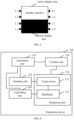
- FIG. 2shows the component structure for the displaying device in the present invention.
- the displaying device 100includes: a calculating unit 110, a creating unit 120, a displaying unit 130, and a controlling unit 140.
- the calculating unit 110is configured to calculate the active display area, and calculate the image area occupied by the display interface according to the active display area.
- the creating unit 120is configured to create the interface image data in the image area and write the image data in the displaying unit 130.
- the displaying unit 130is configured to display the corresponding information according to the image data.
- the displaying unit 130includes an LCD screen 131 and backlights 132.
- the controlling unit 140is configured to control the backlights switch 132 of the displaying unit 130 according to the backlights control command that is generated according to the active display area.
- Backlights 132may be controlled individually or by group. Independent control is for the controlling unit 140 to generate a command for each backlight 132. Group control is for the controlling unit 140 to control backlights 132 by group.
- Two solutionsare provided to control backlights 132:
- the calculating unit 140determines the backlights to be turned on/off according to the active display area ⁇ x,y,x',y'> and generates commands to control backlights 132 in the displaying unit 130.
- the controlling unit 140generates and delivers backlights control commands with the marks of the active display area to the displaying unit 130.
- the displaying unit 130determines the backlights 132 to be turned on/off and controls the backlights 132.
- the first control solution provided in an embodiment of the present inventionis preferred.
- Control of backlights 132need to be synchronized with the screen display.
- the controlling unit 140needs to generate corresponding commands immediately to turn on/off backlights 132.
- the technical solution provided in the embodiment of the present inventionmay adjust the display area of the screen dynamically according to the display content.
- the display areamay be reduced so that only part of the screen is used for display.
- the power consumption of the displaying unitmay be reduced.
- the backlights switchesmay be controlled according to the active display area. When only a little information is to be displayed, only the corresponding backlights are to be turned on. Therefore, the power consumption of the displaying unit may be greatly reduced.
- FIG. 3is the display diagram of the technical solution of the present invention.
- the active display areashows the interface content. According to the display content in application, the position and size of the active display area may be adjusted dynamically. If the content requires full display, the active display area occupies the whole screen.
- the inactive display areadoes not show the interface content.
- the whole inactive areadisplays black or other single color image to differ from the active display area for the user's convenience to look through the content of the active display area.
- the backlights L1 to L8provide the LCD with light source of equal brightness. Most of the backlights of the terminal equipment are uniformly distributed on both sides of the LCD and some others are below the LCD.
- the standby interfacedisplays a little information, so full screen display is unnecessary. Therefore, as shown in FIG. 3 , the upper half screen is the active display area that displays the whole standby information and the lower half gray screen is the inactive display area.
- the backlights that provide the light source for the active display areaare mainly L1, L2, L5 and L6. Therefore, L1, L2, L5 and L6 are turned on to provide the light source and L3, L4, L7 and L8 are turned off to save the power.
- the light of L1, L2, L5 and L6is distributed equally on the active display area by the light guide plates and the standby interface operates normally.
- FIG. 4shows the component structure for embodiment 3 of the displaying device in the present invention.
- the difference between this embodiment and the displaying device illustrated in Fig.1 or in Fig.2is that the LCD screen 131 in the displaying unit 130 is an interactive LCD screen, especially an interactive touch screen.
- the displaying device 100includes: an inputting unit 150, a calculating unit 110, a creating unit 120, a displaying unit 130 and a controlling unit 140.
- the inputting unit 150is configured to receive user's operation in the interactive LCD screen and deliver the command generated by the operation to the calculating unit 110.
- the calculating unit 110is configured to calculate the active display area according to the command, and calculate the image area occupied by the display interface, according to the active display area.
- the creating unit 120is configured to create the interface image data in the image area and write the image data in the displaying unit 130.
- the displaying unit 130is configured to display the corresponding information according to the image data.
- the displaying unit 130includes the touch screen and backlights 132.
- the controlling unit 140is configured to generate backlights control commands according to the active display area and control the switches of backlight 132s in the displaying unit 130.
- Usersmay click on the touch screen and in turn the users operation may change the screen display such as the active display area and the backlights control.
- the usermay control the position of the active display area.
- the usermay click on the screen to light it up and the selected active display area includes the best place for the user to click on.
- the position of the active display areamay be changed by the user's dragging on the screen.
- the corresponding backlightsneed to be controlled at the same time.
- the size of the active display areamay also be changed. The user may drag or drop the area by one angle or the diagonal of the active display area to zoom in and out.
- the size of the active display areais changed, the corresponding backlights need to be controlled at the same time.
- the position and the size of the active display areamay be changed according to the user operation, which is called the interactive part screen. The screen is best applied in the touch screen.
- FIG. 5shows the component structure of the terminal in the present invention.
- the terminal 500includes the displaying device 100.
- the displaying device 100includes: the calculating unit 110, the creating unit 120 and the displaying unit 130.
- the calculating unit 110is configured to calculate the active display area, and calculate the image area occupied by the display interface, according to the active display area.
- the creating unit 120is configured to create the interface image data in the image area and write the image data in the displaying unit 130.
- the displaying unit 130is configured to display the corresponding information according to the image data.
- the working process and principle of the displaying device 100have been described in details in the embodiment of FIG. 1 .
- the technical solution provided in the embodiment of the present inventionmay adjust the display area of the screen dynamically according to the display content.
- the display areamay be reduced so that only part of the screen is used for display. As a result, the power consumption of the displaying unit may be reduced.
- FIG. 6shows the component structure of a terminal provided in the present invention.
- the terminal 500includes the displaying device 100.
- the displaying device 100includes: the calculating unit 110, the creating unit 120, the displaying unit 130 and the controlling unit 140.
- the calculating unit 110is configured to calculate the active display area, and calculate the image area occupied by the display interface, according to the active display area.
- the creating unit 120is configured to create the interface image data in the image area and write the image data in the displaying unit 130.
- the displaying unit 130is configured to display the corresponding information according to the image data.
- the displaying unit 130includes an LCD screen 131 and backlights 132.
- the controlling unit 140is configured to generate backlights control commands according to the active display area and control the switches of backlights 132 in the displaying unit 130.
- Backlights 132may be controlled individually or by group. Independent control is for the controlling unit 140 to generate a command for each backlight 132. Group control is for the controlling unit to control backlights 132 by group.
- Two solutionsare provided to control backlights 132.
- the calculating unit 140determines the backlights to be turned on/off according to the active display area ⁇ x,y,x',y'> and generates commands to control backlights 132 in the displaying unit 130.
- the controlling unit 140generates and delivers backlights control commands with the marks of the active display area to the displaying unit 130.
- the displaying unit 130determines the backlights 132 to be turned on/off and controls the backlights 132.
- the first control solution provided in an embodiment of the present inventionis preferred.
- Control of backlights 132need to be synchronized with the screen display.
- the controlling unit 140needs to generate commands immediately to turn on/off backlights 132.
- the technical solution provided in the embodiment of the present inventionmay adjust the display area of the screen dynamically according to the display content.
- the display areamay be reduced so that only of the screen is used for display.
- the power consumption of the displaying unitmay be reduced.
- the backlights switchesmay be controlled according to the active display area. When only a little information is to be displayed, only the corresponding backlights are to be turned on. Therefore, the power consumption of the displaying unit may be greatly reduced.
- FIG. 7shows the component structure for embodiment 3 of the terminal in the present invention.
- the terminal 500includes the displaying device 100.
- the displaying device 100includes: the inputting unit 150, the calculating unit 110, the creating unit 120, the displaying unit 130 and the controlling unit 140.
- the difference between this embodiment and the first and the second embodimentis that the LCD screen 131 in the displaying unit 130 is an interactive LCD screen, especially an interactive touch screen.
- the inputting unit 150is configured to receive user's operation in the interactive LCD screen and deliver the command generated by the operation to the calculating unit 110.
- the calculating unit 110is configured to calculate the active display area according to the command, and calculate the image area occupied by the display interface, according to the active display area.
- the creating unit 120is configured to create the interface image data in the image area and write the image data in the displaying unit 130.
- the displaying unit 130is configured to display the corresponding information according to the image data.
- the displaying unit 130includes the touch screen and backlights 132.
- the controlling unit 140is configured to generate backlights control commands according to the active display area to turn on/off the backlights 132 in the displaying unit 130.
- Usersmay click on the touch screen and in turn the users operation may change the screen display such as the active display area and the backlights controls.
- the usermay control the position of the active display area.
- the usermay click on the screen to light up the screen and the selected active display area includes the best place for the user to click on.
- the position of the active display areamay also be changed by the user dragging on the screen.
- the corresponding backlightsneed to be controlled at the same time.
- the size of the active display areamay also be changed. The user may drag or drop the area by one angle or the diagonal of the active display area to zoom in and out.
- the size of the active display areachanges, the corresponding backlights need to be turned on/off at the same time.
- the position and the size of the active display areamay be changed according to the user operation, which is called the interactive part screen. The screen is best applied in the touch screen.
- FIG. 8shows a flowchart for the display method in the present invention, including the following blocks:
- the position and the size of the active display areaare calculated based on the interface content.
- x,ystands for the pixel coordinates values at the upper left corner of the active display
- x',ystands for the pixel coordinates values at the lower right corner of the active display.
- All of the interface contentis configured within the area of ⁇ x,y,x',y'>.
- the active display area of ⁇ x,y,x',y'>calculates the image area of the display interface, creates the interface image data in the image area but creates black or other single color image data outside the active display area, and writes the image data in the displaying unit. Part or full screen is displayed according to the image data.
- the technical solution provided in the embodiment of the present inventionmay adjust the display area of the screen dynamically according to the display content.
- the display areamay be reduced so that only part of the screen is used for display. As a result, the power consumption of the displaying unit may be reduced.
- FIG. 9shows a flowchart for the display method in the present invention, including as follows:
- the backlightsmay control independently or by zones.
- the independent controlis to control the command generated by every single backlight.
- the zone controlis to group the backlights and control the backlights by groups.
- Backlightsmay be controlled individually or by group.
- Independent controlis to generate a command for each backlight.
- Group controlis to control backlights by group.
- Control of the backlightsneed to be synchronized with the screen display.
- corresponding control commandsneed to be generated immediately to control the switches of the backlights.
- the technical solution provided in the embodiment of the present inventionmay adjust the display area of the screen dynamically according to the display content.
- the display areamay be reduced so that only part of the screen is used for display.
- the power consumption of the displaying unitmay be reduced.
- the backlightsmay be turned on/off according to the active display area. When only a little information is to be displayed, only the corresponding backlights are to be turned on. Therefore, the power consumption of the displaying unit may be greatly reduced.
- FIG. 10shows a flowchart for embodiment 3 of the display method in the present invention, including as follows:
- This embodimentmay also include S105, which generates backlights control command according to the active display area and controls the switches of the backlights in the displaying unit.
- Usersmay click on the touch screen and in turn the users operation may change the screen display such as the active display area and the backlights controls.
- the usermay control the position of the active display area.
- the usermay click on the screen to light up the screen and the selected active display area includes the best place for the user to click on.
- the position of the active display areamay also be changed by the user dragging on the screen.
- the corresponding backlightsneed to be turned on/off at the same time.
- the size of the active display areamay also be changed. The user may drag or drop the area by one angle or the diagonal of the active display area to zoom in and out.
- the size of the active display areachanges, the corresponding backlights need to be turned on/off at the same time.
- the position and the size of the active display areamay be changed according to the user operation, which is called the interactive part screen. The screen is best applied in the touch screen.
- the LCD screen in this displaying unitis an interactive LCD screen, especially an interactive touch screen.
- the embodiments of methodscorrespond to the embodiments of device. Those not described in the embodiments of methods may refer to the description of the corresponding embodiments of device.
Landscapes
- Physics & Mathematics (AREA)
- Engineering & Computer Science (AREA)
- General Physics & Mathematics (AREA)
- Theoretical Computer Science (AREA)
- Computer Hardware Design (AREA)
- Crystallography & Structural Chemistry (AREA)
- Nonlinear Science (AREA)
- Chemical & Material Sciences (AREA)
- Optics & Photonics (AREA)
- Mathematical Physics (AREA)
- Liquid Crystal Display Device Control (AREA)
- Control Of Indicators Other Than Cathode Ray Tubes (AREA)
- User Interface Of Digital Computer (AREA)
Description
- The present invention mainly relates to the display area, especially to the displaying device that may control the power consumption, and the display method.
- With the increasing development of science and technology, the functions of various hand-held terminal equipment become more and more powerful but the power consumption is rising accordingly. Because the prior art is unable to break through greatly in the battery capacity, various new technologies may not develop well in the terminal equipment by the constraint of the power consumption. The overall power consumption of the equipment is essential to measure the equipment performance. All top manufacturers of the terminal equipment try to reduce the power consumption.
- Currently, a liquid crystal display (LCD) is mostly used for the display module in the terminal equipment. The LCD display module consists of an LCD and a light-emitting diode (LED).LCD itself is not luminous and it is provided light source by the LED. Whether the control liquid crystal layer allows lights to transmit through or control the transmittance strength is determined by modulating the bias voltage of LCD liquid crystal layer and changing the arrangement of liquid crystal molecules. As the light source in the display module of the LCD, the LED provides the LCD with backlight of equal brightness through light guide plates. Considering the local brightness in the LCD, the current LCD manufacturers mostly arrange many LEDs equally for backlight. The display module consumes the major power for the terminal equipment. Take the 24-inch Quarter Video Graphics Array (QVGA, with resolution of 240 × 320) screen for example, the power consumption is about 80 mA to 100 mA, about 1/3 to 1/2 the power consumption of Global System for Mobile Communications (GSM) 900 terminals. Therefore, if the power consumption of the LCD display module may be reduced, the whole consumption of the equipment will be greatly reduced accordingly. What consumes the power most in the LCD display module are the LED backlights. The LCD of a common 24-inch QVGA LCD screen consumes about a dozen mA and an LED consumes about 10 mA. As a result, several LEDs as backlights will consume the electricity of dozens or even hundreds of mA.
- In the prior art regarding LCD display modules, the backlights are controlled uniformly that is they are switched on/off at the same time. When the display screen is required, the host writes display image data in the LCD, and the control module of backlights switches on all the backlights to display the full screen; when the equipment is in standby mode or turned off, the control module turns off all the backlights, and the host stops writing image data to the LCD.
- In implementing the present invention, inventors find that the following disadvantages at least occur in the prior art: The terminal equipment does not require full display in most cases, that is, part of the screen is used to display the whole interface when only a little information is to be displayed. The prior art may not adjust the display area of the screen by the display content. Regardless of the content of the display content, the backlights of the whole display module are turned on to display the full screen. As a result, the display module operates with the most power consumption at any time causing a lot of waste.
- Document
US 2003/0052903 A1 refers to a method and to an apparatus for lighting a display screen that comprises fully illuminating a relevant portion of the display screen, and using reduced illumination on a remaining portion of the display screen. As a result, power consumption is decreased compared to full lighting of the entire display screen. - Document
EP 1 847 984 A1 (SHARP KK [JP]) 24 October 2007 (2007-10-24) describes an LCD display with backlights arranged along an horizontal or vertical edge or underneath the LCD. A control circuit detects the level of light to be displayed in each region and controls the luminance of each backlight in accordance with the detected level. - Document
US 2003/146897 A1 (HUNTER ROBERT J [US]) 7 August 2003 (2003-08-07) describes an LCD display with backlights underneath the LCD panel. Power to backlights underneath the active window is increased to increase the brightness around the active window while power to the remainder of the backlights is decreased. - Document
US 2005/184952 A1 (KONNO AKITOYO [JP] ET AL) 25 August 2005 (2005-08-25) describes adapting the backlight level of regions of an LCD display to the brightness of the video signal in a region. An LCD panel construction with LED backlights arranged on opposite sides of the panel is described. - The present invention is defined by the attached set of claims.
- A displaying device, the terminal of the displaying device, and display method are provided in embodiments of the present invention. The displaying device may adjust the display area of the screen dynamically according to the display content to reduce the cost of displaying unit.
- The technical solutions provided in various embodiments of the present invention are implemented as follows.
- A displaying device includes:
a calculating unit, configured to calculate the active display area that shows the interface content and calculate the image area occupied by the display interface; a creating unit, configured to create an interface image data in the image area and write the image data in the displaying unit; and a displaying unit, configured to display the corresponding information based on the image data. - A terminal includes a displaying device. The displaying device includes: a calculating unit, configured to calculate the active display area that shows the interface content and calculate the image area occupied by the display interface; a creating unit, configured to create an interface image data in the image area and write the image data in the displaying unit; and a displaying unit, configured to display the corresponding information based on the image data.
- A display method includes: calculating the active display area that shows the interface content and the image area occupied by the display interface; creating the interface image data in the image area and writing the interface image data to the displaying unit; and displaying the corresponding information according to the image data.
- The technical solution provided in embodiments of the present invention may adjust the display area of the screen dynamically according to the display content. When only a little information is to be displayed, the display area may be reduced so that only part of the screen is used for display. As a result, the power consumption of the displaying unit is lower. Furthermore, the backlights may be turned on/off to light the active display area only. When a little information is to be displayed, only the corresponding backlights are to be turned on. Therefore, the power consumption of the displaying unit may be greatly reduced.
- To clarify the technical solution in an embodiment of the present invention or the solution using prior art, the drawings used in this embodiment or the prior technical descriptions are described below.
FIG. 1 shows the structure of the displaying device according to the present invention;FIG. 2 shows the structure of the displaying device according to the present invention;FIG. 3 shows the screen display of the technical solution inFIG. 2 ;FIG. 4 shows the structure of the displaying device according to embodiment 3 of the present invention;FIG. 5 shows the structure of the terminal according to the present invention;FIG. 6 shows the structure of the terminal according to the present invention;FIG. 7 shows the structure of the terminal according to embodiment 3 of the present invention;FIG. 8 is a flowchart of the display method according to the present invention;FIG. 9 is a flowchart of the display method according to the present invention; andFIG. 10 is a flowchart of the display method according to embodiment 3 of the present invention.- The following section clearly and fully describes the technical solution provided in the embodiments of the present invention. Obviously, only part of the embodiments of the present invention is involved herein.
- The display interface provided in an embodiment of the present invention does not need full display. Both the position and the size of the display area in the screen may be adjusted dynamically according to the display content, that is, using part of the screen to display the interface. If only part of the screen is used for displaying, the area of displaying interface is called the active display area, and the rest of the screen is called the inactive display area.
FIG. 1 shows the component structure of the displaying device in the present invention. The displayingdevice 100 includes: the calculatingunit 110, the creatingunit 120, and the displayingunit 130.- The calculating
unit 110 is configured to calculate the active display area, and calculate the image area occupied by the display interface according to the active display area. - The active display area shows the area of the interface content.
- The creating
unit 120 is configured to create the interface image data in the image area and write the image data in the displayingunit 130. - The displaying
unit 130 is configured to display the corresponding information according to the image data. The working process and principle of the displayingdevice 100 are described in details below. - When the interface program constructs the interface, the calculating
unit 100 calculates the position and size of the active display area according to the interface content. In calculating the pixel coordinates values <x,y,x',y'> in the active display area, "x,y" stands for the pixel coordinates values at the upper left corner of the active display and"x',y‴ stands for the pixel coordinates values at the lower right corner of the active display. Of course, those skilled in the art also know many other methods. All of the interface content is configured within the area of <x,y,x',y'>. During creating the displayed image, the creatingunit 120, according to the active display area of <x,y,x',y'>, calculates the image area of the display interface, creates the interface image data in the image area but creates black or other single color image data outside the active display area, and writes the image data in the displayingunit 130. The displayingunit 130 displays part or full screen according to the image data. - The technical solution provided in the embodiment of the present invention may adjust the display area of the screen dynamically according to the display content. When only a little information is to be displayed, the display area may be reduced so that only part of the screen is used for display. As a result, the power consumption of the displaying unit may be reduced.
FIG. 2 shows the component structure for the displaying device in the present invention. The displayingdevice 100 includes: a calculatingunit 110, a creatingunit 120, a displayingunit 130, and a controllingunit 140.- The calculating
unit 110 is configured to calculate the active display area, and calculate the image area occupied by the display interface according to the active display area. - The creating
unit 120 is configured to create the interface image data in the image area and write the image data in the displayingunit 130. - The displaying
unit 130 is configured to display the corresponding information according to the image data. The displayingunit 130 includes anLCD screen 131 and backlights 132. The controllingunit 140 is configured to control the backlights switch 132 of the displayingunit 130 according to the backlights control command that is generated according to the active display area. - The difference between this and
Figure 1 is that inFigure 1 whether to display part or full screen, all thebacklights 132 of the displayingunit 130 are turned on. Thebacklights 132 provided in the embodiment may be turned on/off according to the size of the display area. When much information is to be displayed on full screen, the controllingunit 140 generates commands according to the active display area to turn on all thebacklights 132. When only a little information is to be displayed on part of the screen, the controllingunit 140 generates commands according to the active display area to turn on part of thebacklights 132 only. The rest backlights 132 outside the active area are turned off. Backlights 132 may be controlled individually or by group. Independent control is for the controllingunit 140 to generate a command for eachbacklight 132. Group control is for the controllingunit 140 to controlbacklights 132 by group.- Two solutions are provided to control backlights 132: In the first solution, the calculating
unit 140 determines the backlights to be turned on/off according to the active display area <x,y,x',y'> and generates commands to controlbacklights 132 in the displayingunit 130. In the second solution, the controllingunit 140 generates and delivers backlights control commands with the marks of the active display area to the displayingunit 130. The displayingunit 130 determines thebacklights 132 to be turned on/off and controls thebacklights 132. The first control solution provided in an embodiment of the present invention is preferred. - Control of
backlights 132 need to be synchronized with the screen display. When the active display area is changed, the controllingunit 140 needs to generate corresponding commands immediately to turn on/offbacklights 132. - The technical solution provided in the embodiment of the present invention may adjust the display area of the screen dynamically according to the display content. When only a little information is to be displayed, the display area may be reduced so that only part of the screen is used for display. As a result, the power consumption of the displaying unit may be reduced. Furthermore, the backlights switches may be controlled according to the active display area. When only a little information is to be displayed, only the corresponding backlights are to be turned on. Therefore, the power consumption of the displaying unit may be greatly reduced.
- To clarify the technical solution and the beneficial effects in an embodiment of the present invention, a specific instance is taken below.
FIG. 3 is the display diagram of the technical solution of the present invention. - The active display area shows the interface content. According to the display content in application, the position and size of the active display area may be adjusted dynamically. If the content requires full display, the active display area occupies the whole screen.
- The inactive display area does not show the interface content. The whole inactive area displays black or other single color image to differ from the active display area for the user's convenience to look through the content of the active display area.
- The backlights L1 to L8 provide the LCD with light source of equal brightness. Most of the backlights of the terminal equipment are uniformly distributed on both sides of the LCD and some others are below the LCD.
- The standby interface displays a little information, so full screen display is unnecessary. Therefore, as shown in
FIG. 3 , the upper half screen is the active display area that displays the whole standby information and the lower half gray screen is the inactive display area. The backlights that provide the light source for the active display area are mainly L1, L2, L5 and L6. Therefore, L1, L2, L5 and L6 are turned on to provide the light source and L3, L4, L7 and L8 are turned off to save the power. The light of L1, L2, L5 and L6 is distributed equally on the active display area by the light guide plates and the standby interface operates normally. FIG. 4 shows the component structure for embodiment 3 of the displaying device in the present invention. The difference between this embodiment and the displaying device illustrated inFig.1 or inFig.2 is that theLCD screen 131 in the displayingunit 130 is an interactive LCD screen, especially an interactive touch screen. The displayingdevice 100 includes: an inputtingunit 150, a calculatingunit 110, a creatingunit 120, a displayingunit 130 and a controllingunit 140.- The inputting
unit 150 is configured to receive user's operation in the interactive LCD screen and deliver the command generated by the operation to the calculatingunit 110. - The calculating
unit 110 is configured to calculate the active display area according to the command, and calculate the image area occupied by the display interface, according to the active display area. - The creating
unit 120 is configured to create the interface image data in the image area and write the image data in the displayingunit 130. - The displaying
unit 130 is configured to display the corresponding information according to the image data. The displayingunit 130 includes the touch screen and backlights 132. - The controlling
unit 140 is configured to generate backlights control commands according to the active display area and control the switches of backlight 132s in the displayingunit 130. - Users may click on the touch screen and in turn the users operation may change the screen display such as the active display area and the backlights control.
- When displaying part of the screen, the user may control the position of the active display area. In some occasions, the user may click on the screen to light it up and the selected active display area includes the best place for the user to click on. The position of the active display area may be changed by the user's dragging on the screen. When the position of the active display area is changed, the corresponding backlights need to be controlled at the same time. The size of the active display area may also be changed. The user may drag or drop the area by one angle or the diagonal of the active display area to zoom in and out. Likewise, when the size of the active display area is changed, the corresponding backlights need to be controlled at the same time. The position and the size of the active display area may be changed according to the user operation, which is called the interactive part screen. The screen is best applied in the touch screen.
- The backlights control of the touch screen is the same with the technical solutions in the foregoing embodiments.
FIG. 5 shows the component structure of the terminal in the present invention. The terminal 500 includes the displayingdevice 100. The displayingdevice 100 includes: the calculatingunit 110, the creatingunit 120 and the displayingunit 130. The calculatingunit 110 is configured to calculate the active display area, and calculate the image area occupied by the display interface, according to the active display area. The creatingunit 120 is configured to create the interface image data in the image area and write the image data in the displayingunit 130. The displayingunit 130 is configured to display the corresponding information according to the image data. The working process and principle of the displayingdevice 100 have been described in details in the embodiment ofFIG. 1 .- The technical solution provided in the embodiment of the present invention may adjust the display area of the screen dynamically according to the display content. When only a little information is to be displayed, the display area may be reduced so that only part of the screen is used for display. As a result, the power consumption of the displaying unit may be reduced.
FIG. 6 shows the component structure of a terminal provided in the present invention. The terminal 500 includes the displayingdevice 100. The displayingdevice 100 includes: the calculatingunit 110, the creatingunit 120, the displayingunit 130 and the controllingunit 140. The calculatingunit 110 is configured to calculate the active display area, and calculate the image area occupied by the display interface, according to the active display area. The creatingunit 120 is configured to create the interface image data in the image area and write the image data in the displaying unit 130.The displayingunit 130 is configured to display the corresponding information according to the image data. The displayingunit 130 includes anLCD screen 131 and backlights 132. The controllingunit 140 is configured to generate backlights control commands according to the active display area and control the switches ofbacklights 132 in the displayingunit 130.- The difference between this and
Figure 1 is that inFigure 1 , whether to display part of or full screen, all thebacklights 132 of the displayingunit 130 are turned on. Thebacklights 132 provided in the embodiment may be turned on/off according to the size of the display area. When much content for full screen display is required, the controllingunit 140 instructs all thebacklights 132 to be turned on according to the control generated by the active display area. When only a little information is to be displayed on part of the screen, the controllingunit 140 turns on part of thebacklights 132. The rest backlights 132 outside the active area are turned off. Backlights 132 may be controlled individually or by group. Independent control is for the controllingunit 140 to generate a command for eachbacklight 132. Group control is for the controlling unit to controlbacklights 132 by group.- Two solutions are provided to control backlights 132.In the first solution, the calculating
unit 140 determines the backlights to be turned on/off according to the active display area <x,y,x',y'> and generates commands to controlbacklights 132 in the displayingunit 130. In the second solution, the controllingunit 140 generates and delivers backlights control commands with the marks of the active display area to the displayingunit 130. The displayingunit 130 determines thebacklights 132 to be turned on/off and controls thebacklights 132. The first control solution provided in an embodiment of the present invention is preferred. - Control of
backlights 132 need to be synchronized with the screen display. When the active display area is changed, the controllingunit 140 needs to generate commands immediately to turn on/offbacklights 132. - The technical solution provided in the embodiment of the present invention may adjust the display area of the screen dynamically according to the display content. When only a little information is to be displayed, the display area may be reduced so that only of the screen is used for display. As a result, the power consumption of the displaying unit may be reduced. Furthermore, the backlights switches may be controlled according to the active display area. When only a little information is to be displayed, only the corresponding backlights are to be turned on. Therefore, the power consumption of the displaying unit may be greatly reduced.
FIG. 7 shows the component structure for embodiment 3 of the terminal in the present invention. The terminal 500 includes the displayingdevice 100. The displayingdevice 100 includes: the inputtingunit 150, the calculatingunit 110, the creatingunit 120, the displayingunit 130 and the controllingunit 140. The difference between this embodiment and the first and the second embodiment is that theLCD screen 131 in the displayingunit 130 is an interactive LCD screen, especially an interactive touch screen.- The inputting
unit 150 is configured to receive user's operation in the interactive LCD screen and deliver the command generated by the operation to the calculatingunit 110. - The calculating
unit 110 is configured to calculate the active display area according to the command, and calculate the image area occupied by the display interface, according to the active display area. - The creating
unit 120 is configured to create the interface image data in the image area and write the image data in the displayingunit 130. - The displaying
unit 130 is configured to display the corresponding information according to the image data. The displayingunit 130 includes the touch screen and backlights 132. - The controlling
unit 140 is configured to generate backlights control commands according to the active display area to turn on/off thebacklights 132 in the displayingunit 130. - Users may click on the touch screen and in turn the users operation may change the screen display such as the active display area and the backlights controls.
- When displaying part of the screen, the user may control the position of the active display area. In some occasions, the user may click on the screen to light up the screen and the selected active display area includes the best place for the user to click on. The position of the active display area may also be changed by the user dragging on the screen. When the position of the active display area is changed, the corresponding backlights need to be controlled at the same time. The size of the active display area may also be changed. The user may drag or drop the area by one angle or the diagonal of the active display area to zoom in and out. Likewise, when the size of the active display area changes, the corresponding backlights need to be turned on/off at the same time. The position and the size of the active display area may be changed according to the user operation, which is called the interactive part screen. The screen is best applied in the touch screen.
- The backlights control of the touch screen is the same with the technical solutions in the foregoing embodiments.
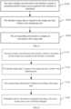
FIG. 8 shows a flowchart for the display method in the present invention, including the following blocks:- S810: The active display area is calculated and the image area occupied by the display interface is calculated according to the active display area. The active display area is the area for displaying the interface content.
- S820: Interface image data is created in the image area and written to the displaying unit.
- S830: The image is displayed according to the data.
- When the interface program constructs the interface, the position and the size of the active display area are calculated based on the interface content. In calculating the pixel coordinates values <x,y,x',y'> in the active display area, "x,y" stands for the pixel coordinates values at the upper left corner of the active display and "x',y"' stands for the pixel coordinates values at the lower right corner of the active display. Of course, those skilled in the art also know many other methods. All of the interface content is configured within the area of <x,y,x',y'>. During creating the displayed image, the active display area of <x,y,x',y'> calculates the image area of the display interface, creates the interface image data in the image area but creates black or other single color image data outside the active display area, and writes the image data in the displaying unit. Part or full screen is displayed according to the image data.
- The technical solution provided in the embodiment of the present invention may adjust the display area of the screen dynamically according to the display content. When only a little information is to be displayed, the display area may be reduced so that only part of the screen is used for display. As a result, the power consumption of the displaying unit may be reduced.
FIG. 9 shows a flowchart for the display method in the present invention, including as follows:- S910: The active display area is calculated and the image area occupied by the display interface is calculated according to the active display area. The active display area is the area for displaying the interface content.
- S920: Interface image data is created in the image area and written to the displaying unit.
- S930: The image is displayed according to the data.
- S940: Backlights control commands are generated according to the active display area to turn on/off the backlights in the displaying unit.
- S940 is performed after the active display area is calculated in S910.
- The difference between this and
Figure 1 is that inFigure 1 , whether to display part or full screen, all the backlights are turned on. The backlights in this however, may be turned on/off according to the size of the display area. - The backlights may control independently or by zones. The independent control is to control the command generated by every single backlight. The zone control is to group the backlights and control the backlights by groups. Backlights may be controlled individually or by group. Independent control is to generate a command for each backlight. Group control is to control backlights by group.
- Control of the backlights need to be synchronized with the screen display. When the active display area is changed, corresponding control commands need to be generated immediately to control the switches of the backlights.
- The technical solution provided in the embodiment of the present invention may adjust the display area of the screen dynamically according to the display content. When only a little information is to be displayed, the display area may be reduced so that only part of the screen is used for display. As a result, the power consumption of the displaying unit may be reduced. Furthermore, the backlights may be turned on/off according to the active display area. When only a little information is to be displayed, only the corresponding backlights are to be turned on. Therefore, the power consumption of the displaying unit may be greatly reduced.
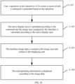
FIG. 10 shows a flowchart for embodiment 3 of the display method in the present invention, including as follows:- S101: User's operation in the interactive LCD screen is received and the corresponding commands are generated.
- S102: The active display area is calculated on basis of the commands and the image area occupied by the display interface is calculated according to the active display area.
- S103: Interface image data is created in the image area and written to the displaying unit.
- S104: The Image is displayed according to the data.
- This embodiment may also include S105, which generates backlights control command according to the active display area and controls the switches of the backlights in the displaying unit.
- Users may click on the touch screen and in turn the users operation may change the screen display such as the active display area and the backlights controls.
- When displaying part of the screen, the user may control the position of the active display area. In some occasions, the user may click on the screen to light up the screen and the selected active display area includes the best place for the user to click on. The position of the active display area may also be changed by the user dragging on the screen. When the position of the active display area changes, the corresponding backlights need to be turned on/off at the same time. The size of the active display area may also be changed. The user may drag or drop the area by one angle or the diagonal of the active display area to zoom in and out. Likewise, when the size of the active display area changes, the corresponding backlights need to be turned on/off at the same time. The position and the size of the active display area may be changed according to the user operation, which is called the interactive part screen. The screen is best applied in the touch screen.
- The difference between this embodiment and the displaying device illustrated in
Fig.1 or inFig.2 is that the LCD screen in this displaying unit is an interactive LCD screen, especially an interactive touch screen. - The embodiments of methods correspond to the embodiments of device. Those not described in the embodiments of methods may refer to the description of the corresponding embodiments of device.
- Only as some good examples of the present invention, the foregoing embodiments shall in no event be construed to limit the scope of the present invention.
Claims (4)
- A displaying device (100), comprising:a calculating unit (110), configured to calculate position and size of an active display area according to an interface content, comprising calculating pixel coordinates values <x,y,x',y'> in the active display area, <x,y> stands for the pixel coordinates values at the upper left corner of the active display area and <x',y'> stands for the pixel coordinates values at the lower right corner of the active display area and all of the interface content is configured within the area of <x,y,x',y'>;a creating unit (120) configured to create interface image data comprising the interface content in the active display area and black or other single color image data outside the active display areaand to write the interface image data in a displaying unit (130);the displaying unit (130) configured to display the interface image data, the displaying unit (130) includes an LCD screen (131) and backlights (132, L1 to L8); anda controlling unit (140), configured to control the backlights (132, L1 to L8) of the displaying unit (130) according to a backlights control command that is generated according to the active display area,wherein the backlights (132, L1 to L8) are configured to be controlled individually by the controlling unit (140); andwherein the backlights (132, L1 to L8) are light sources of equal brightness that provide the LCD screen (131) with light, most of the backlights (132, L1 to L8) are uniformly distributed on two opposing sides of the LCD screen (131) when seen in top view, and some others of the backlights (132, L1 to L8) are located below the LCD screen (131),wherein the backlights (132, L1 to L8) are configured to be turned on/off according to the position and size of the active display area, so that when much information is to be displayed, on the full LCD screen (131), the controlling unit (140) is configured to generate the backlights control command to turn on all the backlights (132, L1 to L8), and when only little information is to be displayed, on part of the LCD screen (131), the controlling unit (140) is configured to generate the backlights control command according to the active display area to turn on part of the backlights (132, L1 to L8) only and remaining backlights (132) outside the active display area are turned off;wherein the size of the active display area is smaller than a size of the full LCD screen (131) when only little information is to be displayed on part of the LCD screen (131).
- The displaying device (100) according to claim 1, wherein a position and size of the active display area are adjusted dynamically according to the interface content.
- A displaying method, wherein the method is used in a displaying device (100), the method comprising:calculating, by a calculating unit (110), a position and size of an active display area according to an interface content, comprising calculating pixel coordinates values <x,y,x',y'> in the active display area, <x,y> stands for the pixel coordinates values at the upper left corner of the active display area and <x',y'> stands for the pixel coordinates values at the lower right corner of the active display area and all of the interface content is configured within the area of <x,y,x',y'>;creating, by a creating unit (120), interface image data comprising the interface content in the active display area and black or other single color image data outside the active display area and writing the interface image data in a displaying unit (130);displaying, by the displaying unit (130), the interface image data, the displaying unit (130) includes an LCD screen (131) and backlights (132, L1 to L8); andcontrolling, by a controlling unit (140), the backlights (132, L1 to L8) of the displaying unit (130) according to a backlights control command that is generated according to the active display area,wherein the backlights (132, L1 to L8) are controlled individually by the controlling unit (140); andwherein the backlights (132, L1 to L8) are light sources of equal brightness that provide the LCD screen (131) with light, most of the backlights (132, L1 to L8) are uniformly distributed on two opposing sides of the LCD screen (131) when seen in top view, and some others of the backlights (132, L1 to L8) are located below the LCD screen (131),wherein the backlights (132, L1 to L8) are turned on/off according to the position and size of the active display area, so that when much information is displayed, on the full LCD screen (131), the controlling unit (140) generates the backlights control command to turn on all the backlights (132, L1 to L8), and when only little information is displayed, on part of the LCD screen (131), the controlling unit (140) generates the backlights control command according to the active display area and turns on part of the backlights (132, L1 to L8) only and remaining backlights (132) outside the active display area are turned off;wherein the size of the active display area is smaller than a size of the full LCD screen (131) when only little information is to be displayed on part of the LCD screen (131).
- The method according to claim 3, wherein a position and size of the active display area are adjusted dynamically according to the interface content.
Applications Claiming Priority (2)
| Application Number | Priority Date | Filing Date | Title |
|---|---|---|---|
| CN2008102474929ACN101465107B (en) | 2008-12-31 | 2008-12-31 | Display device and terminal using the same, and display method |
| EP09172448AEP2204793A1 (en) | 2008-12-31 | 2009-10-07 | Displaying device, terminal of displaying device, and display method |
Related Parent Applications (1)
| Application Number | Title | Priority Date | Filing Date |
|---|---|---|---|
| EP09172448ADivisionEP2204793A1 (en) | 2008-12-31 | 2009-10-07 | Displaying device, terminal of displaying device, and display method |
Publications (2)
| Publication Number | Publication Date |
|---|---|
| EP3493193A1 EP3493193A1 (en) | 2019-06-05 |
| EP3493193B1true EP3493193B1 (en) | 2023-09-06 |
Family
ID=40805662
Family Applications (2)
| Application Number | Title | Priority Date | Filing Date |
|---|---|---|---|
| EP09172448ACeasedEP2204793A1 (en) | 2008-12-31 | 2009-10-07 | Displaying device, terminal of displaying device, and display method |
| EP18208343.6AActiveEP3493193B1 (en) | 2008-12-31 | 2009-10-07 | Displaying device, terminal of displaying device, and display method |
Family Applications Before (1)
| Application Number | Title | Priority Date | Filing Date |
|---|---|---|---|
| EP09172448ACeasedEP2204793A1 (en) | 2008-12-31 | 2009-10-07 | Displaying device, terminal of displaying device, and display method |
Country Status (4)
| Country | Link |
|---|---|
| US (1) | US20100164857A1 (en) |
| EP (2) | EP2204793A1 (en) |
| KR (1) | KR20100080340A (en) |
| CN (1) | CN101465107B (en) |
Families Citing this family (99)
| Publication number | Priority date | Publication date | Assignee | Title |
|---|---|---|---|---|
| JP2011030081A (en)* | 2009-07-28 | 2011-02-10 | Sony Corp | Display device, display system, display method and program |
| CN102063868B (en) | 2009-11-12 | 2013-08-07 | 鸿富锦精密工业(深圳)有限公司 | Electronic device with backlight control and control method thereof |
| CN102137241B (en)* | 2010-01-27 | 2014-03-12 | 联想(北京)有限公司 | Display device and display method thereof |
| EP2357220A1 (en)* | 2010-02-10 | 2011-08-17 | The Procter & Gamble Company | Cleaning composition comprising amylase variants with high stability in the presence of a chelating agent |
| US8922604B2 (en)* | 2010-03-26 | 2014-12-30 | Sharp Kabushiki Kaisha | Image-display device and control method of same |
| CN102087836A (en)* | 2010-04-13 | 2011-06-08 | Tcl集团股份有限公司 | Liquid crystal display system and image display method thereof |
| CN102087818A (en)* | 2010-04-13 | 2011-06-08 | Tcl集团股份有限公司 | Liquid crystal display system |
| KR101329967B1 (en)* | 2010-05-11 | 2013-11-13 | 엘지디스플레이 주식회사 | Back light unit and liquid crystal display device using the same and driving method thereof |
| CN102298899A (en)* | 2010-06-22 | 2011-12-28 | 纬创资通股份有限公司 | Display power saving method and electronic system |
| CN102221873A (en)* | 2010-07-29 | 2011-10-19 | 宇龙计算机通信科技(深圳)有限公司 | Backlight control method and system and mobile terminal |
| US8698859B2 (en) | 2010-10-19 | 2014-04-15 | Blackberry Limited | Display screen having regions of differing pixel density |
| CN101989147A (en)* | 2010-12-09 | 2011-03-23 | 华为终端有限公司 | Method and device for regulating touch screen parameter |
| US9201185B2 (en) | 2011-02-04 | 2015-12-01 | Microsoft Technology Licensing, Llc | Directional backlighting for display panels |
| JPWO2013080444A1 (en) | 2011-11-29 | 2015-04-27 | パナソニックIpマネジメント株式会社 | Display control apparatus, display control method, and display control program |
| US9052414B2 (en) | 2012-02-07 | 2015-06-09 | Microsoft Technology Licensing, Llc | Virtual image device |
| US9354748B2 (en) | 2012-02-13 | 2016-05-31 | Microsoft Technology Licensing, Llc | Optical stylus interaction |
| US8749529B2 (en) | 2012-03-01 | 2014-06-10 | Microsoft Corporation | Sensor-in-pixel display system with near infrared filter |
| USRE48963E1 (en) | 2012-03-02 | 2022-03-08 | Microsoft Technology Licensing, Llc | Connection device for computing devices |
| US8873227B2 (en) | 2012-03-02 | 2014-10-28 | Microsoft Corporation | Flexible hinge support layer |
| US9426905B2 (en) | 2012-03-02 | 2016-08-23 | Microsoft Technology Licensing, Llc | Connection device for computing devices |
| US9460029B2 (en) | 2012-03-02 | 2016-10-04 | Microsoft Technology Licensing, Llc | Pressure sensitive keys |
| US9870066B2 (en) | 2012-03-02 | 2018-01-16 | Microsoft Technology Licensing, Llc | Method of manufacturing an input device |
| US9298236B2 (en) | 2012-03-02 | 2016-03-29 | Microsoft Technology Licensing, Llc | Multi-stage power adapter configured to provide a first power level upon initial connection of the power adapter to the host device and a second power level thereafter upon notification from the host device to the power adapter |
| US9075566B2 (en) | 2012-03-02 | 2015-07-07 | Microsoft Technoogy Licensing, LLC | Flexible hinge spine |
| US9360893B2 (en) | 2012-03-02 | 2016-06-07 | Microsoft Technology Licensing, Llc | Input device writing surface |
| US9064654B2 (en) | 2012-03-02 | 2015-06-23 | Microsoft Technology Licensing, Llc | Method of manufacturing an input device |
| CN102622177A (en)* | 2012-03-07 | 2012-08-01 | 上海华勤通讯技术有限公司 | Mobile terminal and display screen region display method thereof |
| CN102662593A (en)* | 2012-04-16 | 2012-09-12 | 华为终端有限公司 | Multi-size display method and terminal |
| US20130300590A1 (en) | 2012-05-14 | 2013-11-14 | Paul Henry Dietz | Audio Feedback |
| CN103455128A (en)* | 2012-06-04 | 2013-12-18 | 联想(北京)有限公司 | Display method and electronic device |
| US10031556B2 (en) | 2012-06-08 | 2018-07-24 | Microsoft Technology Licensing, Llc | User experience adaptation |
| US9019615B2 (en) | 2012-06-12 | 2015-04-28 | Microsoft Technology Licensing, Llc | Wide field-of-view virtual image projector |
| US8947353B2 (en) | 2012-06-12 | 2015-02-03 | Microsoft Corporation | Photosensor array gesture detection |
| US9459160B2 (en) | 2012-06-13 | 2016-10-04 | Microsoft Technology Licensing, Llc | Input device sensor configuration |
| US9073123B2 (en) | 2012-06-13 | 2015-07-07 | Microsoft Technology Licensing, Llc | Housing vents |
| US9684382B2 (en) | 2012-06-13 | 2017-06-20 | Microsoft Technology Licensing, Llc | Input device configuration having capacitive and pressure sensors |
| US9256089B2 (en) | 2012-06-15 | 2016-02-09 | Microsoft Technology Licensing, Llc | Object-detecting backlight unit |
| US9355345B2 (en) | 2012-07-23 | 2016-05-31 | Microsoft Technology Licensing, Llc | Transparent tags with encoded data |
| US8964379B2 (en) | 2012-08-20 | 2015-02-24 | Microsoft Corporation | Switchable magnetic lock |
| CN102902407B (en)* | 2012-09-12 | 2015-08-05 | 青岛海信移动通信技术股份有限公司 | A kind of touch-screen output display touches the method and apparatus of person's handwriting |
| US9152173B2 (en) | 2012-10-09 | 2015-10-06 | Microsoft Technology Licensing, Llc | Transparent display device |
| US8654030B1 (en) | 2012-10-16 | 2014-02-18 | Microsoft Corporation | Antenna placement |
| WO2014059618A1 (en) | 2012-10-17 | 2014-04-24 | Microsoft Corporation | Graphic formation via material ablation |
| WO2014059625A1 (en) | 2012-10-17 | 2014-04-24 | Microsoft Corporation | Metal alloy injection molding overflows |
| EP2908970B1 (en) | 2012-10-17 | 2018-01-03 | Microsoft Technology Licensing, LLC | Metal alloy injection molding protrusions |
| US8952892B2 (en) | 2012-11-01 | 2015-02-10 | Microsoft Corporation | Input location correction tables for input panels |
| US8786767B2 (en) | 2012-11-02 | 2014-07-22 | Microsoft Corporation | Rapid synchronized lighting and shuttering |
| CN103092322A (en)* | 2012-11-16 | 2013-05-08 | 阎跃鹏 | Area-controllable dual-display screen window, energy-saving display method and electronic equipment |
| CN102981713B (en)* | 2012-11-30 | 2016-04-06 | 北京奇虎科技有限公司 | For the desktop presentation device and method of file |
| US9513748B2 (en) | 2012-12-13 | 2016-12-06 | Microsoft Technology Licensing, Llc | Combined display panel circuit |
| CN102981596A (en)* | 2012-12-21 | 2013-03-20 | 东莞宇龙通信科技有限公司 | Terminal and screen interface display method |
| CN103035209B (en)* | 2012-12-24 | 2015-09-02 | 东莞宇龙通信科技有限公司 | Terminal and screen backlight control method |
| US9176538B2 (en) | 2013-02-05 | 2015-11-03 | Microsoft Technology Licensing, Llc | Input device configurations |
| US10578499B2 (en) | 2013-02-17 | 2020-03-03 | Microsoft Technology Licensing, Llc | Piezo-actuated virtual buttons for touch surfaces |
| CN103176589B (en)* | 2013-03-04 | 2016-02-10 | 东莞宇龙通信科技有限公司 | Screen display method and system for editing content |
| US9638835B2 (en) | 2013-03-05 | 2017-05-02 | Microsoft Technology Licensing, Llc | Asymmetric aberration correcting lens |
| KR102023067B1 (en) | 2013-03-15 | 2019-09-19 | 삼성전자주식회사 | System on chip and method of operating display system having the same |
| US9304549B2 (en) | 2013-03-28 | 2016-04-05 | Microsoft Technology Licensing, Llc | Hinge mechanism for rotatable component attachment |
| CN103345906B (en)* | 2013-03-29 | 2016-08-10 | 青岛海信电器股份有限公司 | Display device |
| US20150220243A1 (en)* | 2013-05-10 | 2015-08-06 | Jinrong Yang | Spatially-enhanced accessibility aid for a display device |
| US8593427B1 (en)* | 2013-05-10 | 2013-11-26 | Jinrong Yang | System and method for managing display power consumption |
| US9552777B2 (en) | 2013-05-10 | 2017-01-24 | Microsoft Technology Licensing, Llc | Phase control backlight |
| KR102070174B1 (en)* | 2013-05-16 | 2020-01-29 | 인텔 코포레이션 | Automatically adjusting display areas to reduce power consumption |
| CN104346049A (en)* | 2013-07-29 | 2015-02-11 | 联想(北京)有限公司 | Display control method and electronic equipment |
| US9448631B2 (en) | 2013-12-31 | 2016-09-20 | Microsoft Technology Licensing, Llc | Input device haptics and pressure sensing |
| WO2015100750A1 (en)* | 2014-01-06 | 2015-07-09 | 华为终端有限公司 | Display control method and device |
| US9317072B2 (en) | 2014-01-28 | 2016-04-19 | Microsoft Technology Licensing, Llc | Hinge mechanism with preset positions |
| US9759854B2 (en) | 2014-02-17 | 2017-09-12 | Microsoft Technology Licensing, Llc | Input device outer layer and backlighting |
| US10120420B2 (en) | 2014-03-21 | 2018-11-06 | Microsoft Technology Licensing, Llc | Lockable display and techniques enabling use of lockable displays |
| CN103915072B (en) | 2014-03-24 | 2016-07-06 | 京东方科技集团股份有限公司 | A kind of display system and driving method thereof |
| CN104978933A (en)* | 2014-04-02 | 2015-10-14 | 中兴通讯股份有限公司 | Method and device for realizing regional display of screen |
| US10324733B2 (en) | 2014-07-30 | 2019-06-18 | Microsoft Technology Licensing, Llc | Shutdown notifications |
| US20160071466A1 (en)* | 2014-09-05 | 2016-03-10 | Royole Corporation | Method for controlling a display |
| US10593296B2 (en) | 2014-09-05 | 2020-03-17 | Royole Corporation | Electronic device and method for selectively illuminating regions of a display screen of the electronic device |
| US9424048B2 (en) | 2014-09-15 | 2016-08-23 | Microsoft Technology Licensing, Llc | Inductive peripheral retention device |
| US9447620B2 (en) | 2014-09-30 | 2016-09-20 | Microsoft Technology Licensing, Llc | Hinge mechanism with multiple preset positions |
| CN104714622A (en)* | 2015-03-03 | 2015-06-17 | 上海新岸线电子技术有限公司 | Energy-saving type display screen and mobile terminal |
| CN104795053B (en)* | 2015-04-27 | 2018-07-13 | 三星电子(中国)研发中心 | Method, apparatus and terminal for adjusting screen intensity |
| US10222889B2 (en) | 2015-06-03 | 2019-03-05 | Microsoft Technology Licensing, Llc | Force inputs and cursor control |
| US10416799B2 (en) | 2015-06-03 | 2019-09-17 | Microsoft Technology Licensing, Llc | Force sensing and inadvertent input control of an input device |
| KR20160144730A (en)* | 2015-06-09 | 2016-12-19 | 삼성전자주식회사 | Display panel and display apparatus |
| US9752361B2 (en) | 2015-06-18 | 2017-09-05 | Microsoft Technology Licensing, Llc | Multistage hinge |
| US9864415B2 (en) | 2015-06-30 | 2018-01-09 | Microsoft Technology Licensing, Llc | Multistage friction hinge |
| KR20170011181A (en)* | 2015-07-21 | 2017-02-02 | 엘지전자 주식회사 | Mobile terminal and paying method using extended display and finger scan thereof |
| CN105390109A (en)* | 2015-12-07 | 2016-03-09 | 惠州Tcl移动通信有限公司 | Driving display method and liquid crystal display device |
| CN107124902B (en) | 2015-12-31 | 2020-01-17 | 华为技术有限公司 | Display backlight control method, device and terminal |
| US10061385B2 (en) | 2016-01-22 | 2018-08-28 | Microsoft Technology Licensing, Llc | Haptic feedback for a touch input device |
| CN105845100B (en)* | 2016-03-21 | 2018-11-16 | 南京信息工程大学 | A kind of screen regional backlight dynamical adjusting method |
| US10344797B2 (en) | 2016-04-05 | 2019-07-09 | Microsoft Technology Licensing, Llc | Hinge with multiple preset positions |
| CN106250400B (en)* | 2016-07-19 | 2021-03-26 | 腾讯科技(深圳)有限公司 | Audio data processing method, device and system |
| US10037057B2 (en) | 2016-09-22 | 2018-07-31 | Microsoft Technology Licensing, Llc | Friction hinge |
| CN108345375A (en)* | 2017-01-25 | 2018-07-31 | 中兴通讯股份有限公司 | Screen display method and device, terminal |
| CN107452321A (en)* | 2017-09-28 | 2017-12-08 | 上海与德科技有限公司 | The Split-screen display system of electric advertisement screen |
| CN108052257A (en)* | 2017-12-11 | 2018-05-18 | 江苏铁锚玻璃股份有限公司 | Information displaying method, the terminal device and storage medium with transparent display |
| US11287651B2 (en)* | 2018-05-04 | 2022-03-29 | Harman International Industries, Incorporated | Reconfigurable optics for multi-plane heads-up displays |
| CN108766369A (en)* | 2018-05-31 | 2018-11-06 | 联想(北京)有限公司 | A kind of display equipment and display control method |
| CN109283996B (en)* | 2018-10-24 | 2021-06-01 | Oppo(重庆)智能科技有限公司 | Display control method and related product |
| CN111208894A (en)* | 2018-11-01 | 2020-05-29 | 西安易朴通讯技术有限公司 | Screen display control method and system |
| CN112543495B (en)* | 2019-09-23 | 2022-09-02 | 华为技术有限公司 | Display control method and electronic equipment |
Citations (3)
| Publication number | Priority date | Publication date | Assignee | Title |
|---|---|---|---|---|
| US20030146897A1 (en)* | 2002-02-07 | 2003-08-07 | Hunter Robert J. | Method and apparatus to reduce power consumption of a computer system display screen |
| US20050184952A1 (en)* | 2004-02-09 | 2005-08-25 | Akitoyo Konno | Liquid crystal display apparatus |
| EP1847984A1 (en)* | 2005-01-25 | 2007-10-24 | Sharp Kabushiki Kaisha | Display device, instrument panel, automatic vehicle, and method of driving display device |
Family Cites Families (9)
| Publication number | Priority date | Publication date | Assignee | Title |
|---|---|---|---|---|
| US5390295A (en)* | 1991-12-20 | 1995-02-14 | International Business Machines Corporation | Method and apparatus for proportionally displaying windows on a computer display screen |
| US5621429A (en)* | 1993-03-16 | 1997-04-15 | Hitachi, Ltd. | Video data display controlling method and video data display processing system |
| JP4355977B2 (en)* | 1999-11-12 | 2009-11-04 | ソニー株式会社 | Image display device and illumination control method in image display device |
| US20030052903A1 (en) | 2001-09-20 | 2003-03-20 | Weast John C. | Method and apparatus for focus based lighting |
| US6801811B2 (en)* | 2001-12-27 | 2004-10-05 | Hewlett-Packard Development Company, L.P. | Software-directed, energy-aware control of display |
| US6912664B2 (en)* | 2002-02-21 | 2005-06-28 | Hewlett-Packard Development Company, L.P. | Energy-aware software-controlled plurality of displays |
| US20040032400A1 (en)* | 2002-08-14 | 2004-02-19 | Freeman Mark T. | Method and systems for managing the display of digital content |
| JP2004361618A (en)* | 2003-06-04 | 2004-12-24 | Hitachi Displays Ltd | Liquid crystal display |
| CN101256746A (en)* | 2007-07-11 | 2008-09-03 | 康佳集团股份有限公司 | Method for controlling mobile telephone LCD screen backlight |
- 2008
- 2008-12-31CNCN2008102474929Apatent/CN101465107B/enactiveActive
- 2009
- 2009-10-07EPEP09172448Apatent/EP2204793A1/ennot_activeCeased
- 2009-10-07EPEP18208343.6Apatent/EP3493193B1/enactiveActive
- 2009-10-14USUS12/578,699patent/US20100164857A1/ennot_activeAbandoned
- 2009-10-30KRKR1020090104378Apatent/KR20100080340A/ennot_activeCeased
Patent Citations (3)
| Publication number | Priority date | Publication date | Assignee | Title |
|---|---|---|---|---|
| US20030146897A1 (en)* | 2002-02-07 | 2003-08-07 | Hunter Robert J. | Method and apparatus to reduce power consumption of a computer system display screen |
| US20050184952A1 (en)* | 2004-02-09 | 2005-08-25 | Akitoyo Konno | Liquid crystal display apparatus |
| EP1847984A1 (en)* | 2005-01-25 | 2007-10-24 | Sharp Kabushiki Kaisha | Display device, instrument panel, automatic vehicle, and method of driving display device |
Also Published As
| Publication number | Publication date |
|---|---|
| KR20100080340A (en) | 2010-07-08 |
| EP2204793A1 (en) | 2010-07-07 |
| EP3493193A1 (en) | 2019-06-05 |
| CN101465107A (en) | 2009-06-24 |
| CN101465107B (en) | 2010-12-08 |
| US20100164857A1 (en) | 2010-07-01 |
Similar Documents
| Publication | Publication Date | Title |
|---|---|---|
| EP3493193B1 (en) | Displaying device, terminal of displaying device, and display method | |
| US9348502B2 (en) | Dimming method and display apparatus using the same | |
| KR101958870B1 (en) | Display control method and apparatus for power saving | |
| CN103035209B (en) | Terminal and screen backlight control method | |
| US20100328363A1 (en) | Information processing apparatus and method for controlling luminance | |
| US20170295343A1 (en) | Low Power Consumption Display Device | |
| US8976322B2 (en) | Active matrix organic light-emitting diode display and method of controlling display thereof | |
| CN102216975A (en) | Led backlight system | |
| CN101751864A (en) | Backlight control method, system and electronic display apparatus | |
| JP2009294637A (en) | Liquid crystal display and driving method thereof | |
| US20110261087A1 (en) | Display brightness control method | |
| CN103021348A (en) | Display device and screen backlight control method | |
| KR102685972B1 (en) | A control apparatus and method of a monitor for reducing the power consumption of a monitor | |
| US20040233146A1 (en) | Selective window display | |
| US20130093797A1 (en) | Backlight control unit and display device using same and backlight control method | |
| KR20150121783A (en) | Display device, method for driving the same and image display system including the same | |
| CN103631552B (en) | Method and device for realizing energy conservation and fine control of display module | |
| KR102516893B1 (en) | A control apparatus and method of a monitor for reducing the power consumption of a monitor | |
| KR102507174B1 (en) | A control apparatus and method of a monitor for reducing the power consumption of a monitor | |
| EP4485055A1 (en) | Peep-proof control method for liquid crystal display device, and liquid crystal display device | |
| CN110910839A (en) | Control method and control system of display module | |
| KR20200056096A (en) | Liquid Crystal Display Device And Driving Method Thereof | |
| JP5193442B2 (en) | Information processing apparatus and control method | |
| KR20180079610A (en) | Display device and driving method using the same | |
| CN117409730A (en) | Backlight adjusting method of display screen, driving chip and display device |
Legal Events
| Date | Code | Title | Description |
|---|---|---|---|
| PUAI | Public reference made under article 153(3) epc to a published international application that has entered the european phase | Free format text:ORIGINAL CODE: 0009012 | |
| STAA | Information on the status of an ep patent application or granted ep patent | Free format text:STATUS: REQUEST FOR EXAMINATION WAS MADE | |
| 17P | Request for examination filed | Effective date:20181126 | |
| AC | Divisional application: reference to earlier application | Ref document number:2204793 Country of ref document:EP Kind code of ref document:P | |
| AK | Designated contracting states | Kind code of ref document:A1 Designated state(s):AT BE BG CH CY CZ DE DK EE ES FI FR GB GR HR HU IE IS IT LI LT LU LV MC MK MT NL NO PL PT RO SE SI SK SM TR | |
| STAA | Information on the status of an ep patent application or granted ep patent | Free format text:STATUS: EXAMINATION IS IN PROGRESS | |
| 17Q | First examination report despatched | Effective date:20211126 | |
| GRAP | Despatch of communication of intention to grant a patent | Free format text:ORIGINAL CODE: EPIDOSNIGR1 | |
| STAA | Information on the status of an ep patent application or granted ep patent | Free format text:STATUS: GRANT OF PATENT IS INTENDED | |
| INTG | Intention to grant announced | Effective date:20230428 | |
| GRAS | Grant fee paid | Free format text:ORIGINAL CODE: EPIDOSNIGR3 | |
| GRAA | (expected) grant | Free format text:ORIGINAL CODE: 0009210 | |
| STAA | Information on the status of an ep patent application or granted ep patent | Free format text:STATUS: THE PATENT HAS BEEN GRANTED | |
| AC | Divisional application: reference to earlier application | Ref document number:2204793 Country of ref document:EP Kind code of ref document:P | |
| AK | Designated contracting states | Kind code of ref document:B1 Designated state(s):AT BE BG CH CY CZ DE DK EE ES FI FR GB GR HR HU IE IS IT LI LT LU LV MC MK MT NL NO PL PT RO SE SI SK SM TR | |
| REG | Reference to a national code | Ref country code:GB Ref legal event code:FG4D | |
| REG | Reference to a national code | Ref country code:CH Ref legal event code:EP | |
| REG | Reference to a national code | Ref country code:IE Ref legal event code:FG4D | |
| REG | Reference to a national code | Ref country code:DE Ref legal event code:R096 Ref document number:602009065000 Country of ref document:DE | |
| REG | Reference to a national code | Ref country code:LT Ref legal event code:MG9D | |
| REG | Reference to a national code | Ref country code:NL Ref legal event code:MP Effective date:20230906 | |
| PG25 | Lapsed in a contracting state [announced via postgrant information from national office to epo] | Ref country code:GR Free format text:LAPSE BECAUSE OF FAILURE TO SUBMIT A TRANSLATION OF THE DESCRIPTION OR TO PAY THE FEE WITHIN THE PRESCRIBED TIME-LIMIT Effective date:20231207 | |
| PG25 | Lapsed in a contracting state [announced via postgrant information from national office to epo] | Ref country code:SE Free format text:LAPSE BECAUSE OF FAILURE TO SUBMIT A TRANSLATION OF THE DESCRIPTION OR TO PAY THE FEE WITHIN THE PRESCRIBED TIME-LIMIT Effective date:20230906 Ref country code:NO Free format text:LAPSE BECAUSE OF FAILURE TO SUBMIT A TRANSLATION OF THE DESCRIPTION OR TO PAY THE FEE WITHIN THE PRESCRIBED TIME-LIMIT Effective date:20231206 Ref country code:LV Free format text:LAPSE BECAUSE OF FAILURE TO SUBMIT A TRANSLATION OF THE DESCRIPTION OR TO PAY THE FEE WITHIN THE PRESCRIBED TIME-LIMIT Effective date:20230906 Ref country code:LT Free format text:LAPSE BECAUSE OF FAILURE TO SUBMIT A TRANSLATION OF THE DESCRIPTION OR TO PAY THE FEE WITHIN THE PRESCRIBED TIME-LIMIT Effective date:20230906 Ref country code:HR Free format text:LAPSE BECAUSE OF FAILURE TO SUBMIT A TRANSLATION OF THE DESCRIPTION OR TO PAY THE FEE WITHIN THE PRESCRIBED TIME-LIMIT Effective date:20230906 Ref country code:GR Free format text:LAPSE BECAUSE OF FAILURE TO SUBMIT A TRANSLATION OF THE DESCRIPTION OR TO PAY THE FEE WITHIN THE PRESCRIBED TIME-LIMIT Effective date:20231207 Ref country code:FI Free format text:LAPSE BECAUSE OF FAILURE TO SUBMIT A TRANSLATION OF THE DESCRIPTION OR TO PAY THE FEE WITHIN THE PRESCRIBED TIME-LIMIT Effective date:20230906 | |
| REG | Reference to a national code | Ref country code:AT Ref legal event code:MK05 Ref document number:1609614 Country of ref document:AT Kind code of ref document:T Effective date:20230906 | |
| PG25 | Lapsed in a contracting state [announced via postgrant information from national office to epo] | Ref country code:NL Free format text:LAPSE BECAUSE OF FAILURE TO SUBMIT A TRANSLATION OF THE DESCRIPTION OR TO PAY THE FEE WITHIN THE PRESCRIBED TIME-LIMIT Effective date:20230906 | |
| PG25 | Lapsed in a contracting state [announced via postgrant information from national office to epo] | Ref country code:IS Free format text:LAPSE BECAUSE OF FAILURE TO SUBMIT A TRANSLATION OF THE DESCRIPTION OR TO PAY THE FEE WITHIN THE PRESCRIBED TIME-LIMIT Effective date:20240106 | |
| PG25 | Lapsed in a contracting state [announced via postgrant information from national office to epo] | Ref country code:AT Free format text:LAPSE BECAUSE OF FAILURE TO SUBMIT A TRANSLATION OF THE DESCRIPTION OR TO PAY THE FEE WITHIN THE PRESCRIBED TIME-LIMIT Effective date:20230906 | |
| PG25 | Lapsed in a contracting state [announced via postgrant information from national office to epo] | Ref country code:ES Free format text:LAPSE BECAUSE OF FAILURE TO SUBMIT A TRANSLATION OF THE DESCRIPTION OR TO PAY THE FEE WITHIN THE PRESCRIBED TIME-LIMIT Effective date:20230906 | |
| PG25 | Lapsed in a contracting state [announced via postgrant information from national office to epo] | Ref country code:SM Free format text:LAPSE BECAUSE OF FAILURE TO SUBMIT A TRANSLATION OF THE DESCRIPTION OR TO PAY THE FEE WITHIN THE PRESCRIBED TIME-LIMIT Effective date:20230906 Ref country code:RO Free format text:LAPSE BECAUSE OF FAILURE TO SUBMIT A TRANSLATION OF THE DESCRIPTION OR TO PAY THE FEE WITHIN THE PRESCRIBED TIME-LIMIT Effective date:20230906 Ref country code:IS Free format text:LAPSE BECAUSE OF FAILURE TO SUBMIT A TRANSLATION OF THE DESCRIPTION OR TO PAY THE FEE WITHIN THE PRESCRIBED TIME-LIMIT Effective date:20240106 Ref country code:ES Free format text:LAPSE BECAUSE OF FAILURE TO SUBMIT A TRANSLATION OF THE DESCRIPTION OR TO PAY THE FEE WITHIN THE PRESCRIBED TIME-LIMIT Effective date:20230906 Ref country code:EE Free format text:LAPSE BECAUSE OF FAILURE TO SUBMIT A TRANSLATION OF THE DESCRIPTION OR TO PAY THE FEE WITHIN THE PRESCRIBED TIME-LIMIT Effective date:20230906 Ref country code:CZ Free format text:LAPSE BECAUSE OF FAILURE TO SUBMIT A TRANSLATION OF THE DESCRIPTION OR TO PAY THE FEE WITHIN THE PRESCRIBED TIME-LIMIT Effective date:20230906 Ref country code:AT Free format text:LAPSE BECAUSE OF FAILURE TO SUBMIT A TRANSLATION OF THE DESCRIPTION OR TO PAY THE FEE WITHIN THE PRESCRIBED TIME-LIMIT Effective date:20230906 Ref country code:SK Free format text:LAPSE BECAUSE OF FAILURE TO SUBMIT A TRANSLATION OF THE DESCRIPTION OR TO PAY THE FEE WITHIN THE PRESCRIBED TIME-LIMIT Effective date:20230906 Ref country code:PT Free format text:LAPSE BECAUSE OF FAILURE TO SUBMIT A TRANSLATION OF THE DESCRIPTION OR TO PAY THE FEE WITHIN THE PRESCRIBED TIME-LIMIT Effective date:20240108 | |
| PG25 | Lapsed in a contracting state [announced via postgrant information from national office to epo] | Ref country code:PL Free format text:LAPSE BECAUSE OF FAILURE TO SUBMIT A TRANSLATION OF THE DESCRIPTION OR TO PAY THE FEE WITHIN THE PRESCRIBED TIME-LIMIT Effective date:20230906 Ref country code:IT Free format text:LAPSE BECAUSE OF FAILURE TO SUBMIT A TRANSLATION OF THE DESCRIPTION OR TO PAY THE FEE WITHIN THE PRESCRIBED TIME-LIMIT Effective date:20230906 | |
| REG | Reference to a national code | Ref country code:CH Ref legal event code:PL | |
| REG | Reference to a national code | Ref country code:DE Ref legal event code:R097 Ref document number:602009065000 Country of ref document:DE | |
| REG | Reference to a national code | Ref country code:BE Ref legal event code:MM Effective date:20231031 | |
| PG25 | Lapsed in a contracting state [announced via postgrant information from national office to epo] | Ref country code:LU Free format text:LAPSE BECAUSE OF NON-PAYMENT OF DUE FEES Effective date:20231007 | |
| PG25 | Lapsed in a contracting state [announced via postgrant information from national office to epo] | Ref country code:LU Free format text:LAPSE BECAUSE OF NON-PAYMENT OF DUE FEES Effective date:20231007 | |
| PG25 | Lapsed in a contracting state [announced via postgrant information from national office to epo] | Ref country code:MC Free format text:LAPSE BECAUSE OF FAILURE TO SUBMIT A TRANSLATION OF THE DESCRIPTION OR TO PAY THE FEE WITHIN THE PRESCRIBED TIME-LIMIT Effective date:20230906 | |
| PG25 | Lapsed in a contracting state [announced via postgrant information from national office to epo] | Ref country code:DK Free format text:LAPSE BECAUSE OF FAILURE TO SUBMIT A TRANSLATION OF THE DESCRIPTION OR TO PAY THE FEE WITHIN THE PRESCRIBED TIME-LIMIT Effective date:20230906 | |
| PLBE | No opposition filed within time limit | Free format text:ORIGINAL CODE: 0009261 | |
| STAA | Information on the status of an ep patent application or granted ep patent | Free format text:STATUS: NO OPPOSITION FILED WITHIN TIME LIMIT | |
| PG25 | Lapsed in a contracting state [announced via postgrant information from national office to epo] | Ref country code:CH Free format text:LAPSE BECAUSE OF NON-PAYMENT OF DUE FEES Effective date:20231031 | |
| PG25 | Lapsed in a contracting state [announced via postgrant information from national office to epo] | Ref country code:MC Free format text:LAPSE BECAUSE OF FAILURE TO SUBMIT A TRANSLATION OF THE DESCRIPTION OR TO PAY THE FEE WITHIN THE PRESCRIBED TIME-LIMIT Effective date:20230906 Ref country code:DK Free format text:LAPSE BECAUSE OF FAILURE TO SUBMIT A TRANSLATION OF THE DESCRIPTION OR TO PAY THE FEE WITHIN THE PRESCRIBED TIME-LIMIT Effective date:20230906 Ref country code:CH Free format text:LAPSE BECAUSE OF NON-PAYMENT OF DUE FEES Effective date:20231031 Ref country code:SI Free format text:LAPSE BECAUSE OF FAILURE TO SUBMIT A TRANSLATION OF THE DESCRIPTION OR TO PAY THE FEE WITHIN THE PRESCRIBED TIME-LIMIT Effective date:20230906 | |
| 26N | No opposition filed | Effective date:20240607 | |
| PG25 | Lapsed in a contracting state [announced via postgrant information from national office to epo] | Ref country code:BE Free format text:LAPSE BECAUSE OF NON-PAYMENT OF DUE FEES Effective date:20231031 | |
| PG25 | Lapsed in a contracting state [announced via postgrant information from national office to epo] | Ref country code:IE Free format text:LAPSE BECAUSE OF NON-PAYMENT OF DUE FEES Effective date:20231007 | |
| PGFP | Annual fee paid to national office [announced via postgrant information from national office to epo] | Ref country code:GB Payment date:20240829 Year of fee payment:16 | |
| PG25 | Lapsed in a contracting state [announced via postgrant information from national office to epo] | Ref country code:FR Free format text:LAPSE BECAUSE OF NON-PAYMENT OF DUE FEES Effective date:20231106 | |
| PG25 | Lapsed in a contracting state [announced via postgrant information from national office to epo] | Ref country code:IE Free format text:LAPSE BECAUSE OF NON-PAYMENT OF DUE FEES Effective date:20231007 Ref country code:FR Free format text:LAPSE BECAUSE OF NON-PAYMENT OF DUE FEES Effective date:20231106 | |
| PG25 | Lapsed in a contracting state [announced via postgrant information from national office to epo] | Ref country code:BG Free format text:LAPSE BECAUSE OF FAILURE TO SUBMIT A TRANSLATION OF THE DESCRIPTION OR TO PAY THE FEE WITHIN THE PRESCRIBED TIME-LIMIT Effective date:20230906 | |
| PG25 | Lapsed in a contracting state [announced via postgrant information from national office to epo] | Ref country code:BG Free format text:LAPSE BECAUSE OF FAILURE TO SUBMIT A TRANSLATION OF THE DESCRIPTION OR TO PAY THE FEE WITHIN THE PRESCRIBED TIME-LIMIT Effective date:20230906 | |
| PGFP | Annual fee paid to national office [announced via postgrant information from national office to epo] | Ref country code:DE Payment date:20240904 Year of fee payment:16 | |
| PG25 | Lapsed in a contracting state [announced via postgrant information from national office to epo] | Ref country code:CY Free format text:LAPSE BECAUSE OF FAILURE TO SUBMIT A TRANSLATION OF THE DESCRIPTION OR TO PAY THE FEE WITHIN THE PRESCRIBED TIME-LIMIT; INVALID AB INITIO Effective date:20091007 | |
| PG25 | Lapsed in a contracting state [announced via postgrant information from national office to epo] | Ref country code:HU Free format text:LAPSE BECAUSE OF FAILURE TO SUBMIT A TRANSLATION OF THE DESCRIPTION OR TO PAY THE FEE WITHIN THE PRESCRIBED TIME-LIMIT; INVALID AB INITIO Effective date:20091007 |