EP3492368B1 - Root rib for joining an aircraft wing to a wing box and method of manufacturing an aircraft with such a rib - Google Patents
Root rib for joining an aircraft wing to a wing box and method of manufacturing an aircraft with such a ribDownload PDFInfo
- Publication number
- EP3492368B1 EP3492368B1EP18208857.5AEP18208857AEP3492368B1EP 3492368 B1EP3492368 B1EP 3492368B1EP 18208857 AEP18208857 AEP 18208857AEP 3492368 B1EP3492368 B1EP 3492368B1
- Authority
- EP
- European Patent Office
- Prior art keywords
- orifices
- junction
- flange
- rib
- main web
- Prior art date
- Legal status (The legal status is an assumption and is not a legal conclusion. Google has not performed a legal analysis and makes no representation as to the accuracy of the status listed.)
- Active
Links
- 238000004519manufacturing processMethods0.000titleclaimsdescription43
- 238000000034methodMethods0.000claimsdescription38
- 230000006835compressionEffects0.000claimsdescription19
- 238000007906compressionMethods0.000claimsdescription19
- 210000000056organAnatomy0.000description14
- 238000005553drillingMethods0.000description2
- 238000001125extrusionMethods0.000description2
- 238000003754machiningMethods0.000description2
- 238000011144upstream manufacturingMethods0.000description2
- 238000003466weldingMethods0.000description2
- 241000897276TermesSpecies0.000description1
- 240000008042Zea maysSpecies0.000description1
- 238000012550auditMethods0.000description1
- 239000011324beadSubstances0.000description1
- 238000005452bendingMethods0.000description1
- 238000010586diagramMethods0.000description1
- 238000005242forgingMethods0.000description1
- 239000000463materialSubstances0.000description1
- 238000000465mouldingMethods0.000description1
- 239000003351stiffenerSubstances0.000description1
- 238000003756stirringMethods0.000description1
Images


Classifications
- B—PERFORMING OPERATIONS; TRANSPORTING
- B64—AIRCRAFT; AVIATION; COSMONAUTICS
- B64C—AEROPLANES; HELICOPTERS
- B64C1/00—Fuselages; Constructional features common to fuselages, wings, stabilising surfaces or the like
- B64C1/26—Attaching the wing or tail units or stabilising surfaces
- B—PERFORMING OPERATIONS; TRANSPORTING
- B64—AIRCRAFT; AVIATION; COSMONAUTICS
- B64C—AEROPLANES; HELICOPTERS
- B64C3/00—Wings
- B64C3/18—Spars; Ribs; Stringers
- B64C3/187—Ribs
- B—PERFORMING OPERATIONS; TRANSPORTING
- B64—AIRCRAFT; AVIATION; COSMONAUTICS
- B64C—AEROPLANES; HELICOPTERS
- B64C1/00—Fuselages; Constructional features common to fuselages, wings, stabilising surfaces or the like
- B64C1/06—Frames; Stringers; Longerons ; Fuselage sections
Definitions
- the present inventionrelates to the field of aircraft structure, and relates more particularly to a junction rib intended for the wing-central box junction of the wing of an aircraft, a method of manufacturing such a junction rib, the use of this junction rib or of this method within a method of manufacturing a central wing module for an aircraft, the use of the latter method within a method of manufacturing a fuselage section for aircraft, and finally the use of the latter process within a manufacturing process of an aircraft.
- the fuselageIn an aircraft comprising a fuselage and a wing comprising two opposite symmetrical wings fixed to the fuselage, the fuselage generally incorporates a box-shaped structure, called a “central wing box”, on which respective wing structures are fixed, also in box-shaped and generally referred to as "wing side boxes”.
- the central wing boxtypically comprises an upper panel, also called the upper panel, a lower panel, also called the lower surface panel, as well as a front spar and a rear spar which each connect the lower panel to the upper panel.
- the central wing boxgenerally incorporates internal stiffening ribs interconnecting the lower and upper panels and the front and rear side members.
- each wing to the fuselageis provided by a junction rib acting as a structural interface between the corresponding side wing box and the central wing box.
- the junction ribgenerally comprises a web, and a set of cross-sectional or tee-shaped elements arranged around the periphery of the web and fixed to it by means of shear bolts, as shown for example on page 283 from the book by Michael Chun-Yung Niu, Airframe Structural Design (1988 ).
- Each of the profiled elementscomprises a fin or branch which is fixed to a corresponding panel or spar of the central wing box, together with one or more angled fittings, and another fin or branch which is fixed to a corresponding panel or spar of the box wing side, together with one or more other angled fittings.
- the fastening of the fins and fittings to the panels and side membersis generally carried out by means of shear bolts
- rib and profiled elementsrequire that the operations of positioning and fixing a major part of these elements take place in advanced phases of the aircraft assembly process, in particular in the final assembly phase during which the wings are attached to the fuselage.
- the final assembly phaseis a particularly expensive phase with regard to the entire assembly process of an aircraft.
- the object of the inventionis in particular to provide a simple, economical and effective solution to this problem.
- junction ribintended for the wing-central wing box junction of an aircraft, comprising a main wing, as well as an upper fin and a lower fin which extend from the main wing, d 'a first side with respect to the main veil.
- the main webhas a junction surface arranged on a second side opposite to the first side, the main web comprising rows of orifices opening out on the second side into the junction surface and on the first side, the rows of orifices comprising at least a first row of orifices formed in an upper part of the main web and extending from a front side to a rear side of the junction rib, and a second row of holes formed in a lower part of the main web and extending from the front side to the side rear of the junction rib, each of the rows of orifices comprising orifices in the free state.
- upper partand “lower part”, it should be understood that the upper part extends generally above the lower part.
- openings in the free stateit should be understood that the orifices are unoccupied, that is to say capable of subsequently receiving fixing members.
- junction ribthus produced allows the junction of a wing to a section of the aircraft fuselage in a particularly simple and efficient manner, in particular making it possible to minimize the number and the complexity of the operations remaining to be carried out at the stage of final assembly of the aircraft, as will appear more clearly in what follows.
- the rows of holesinclude a third row of holes formed in the upper part of the main web and extending from the front side to the rear side of the junction rib, so that the first and third rows of orifices are respectively arranged on either side of the upper fin.
- the main webis thus able to directly take up the tensile forces of upper fittings, as will appear more clearly in what follows.
- the junction ribhas an extension which is inclined with respect to the junction surface and which extends on the second side from an upper end of the upper part of the main web, so as to form an obtuse angle. with the upper fin in cross section.
- the junction ribfurther comprises a front fin and a rear fin which extend from the main web, on the first side of the main web, and the rows of orifices further include a fourth row of orifices formed in a front portion of the main web and extending from a lower side to an upper side of the junction rib, and a fifth row of orifices formed in a rear portion of the main web and extending from the lower side towards the upper side of the connecting rib.
- each of the profiled elements other than the upper sectionhas an angled configuration.
- the rows of orificesadvantageously furthermore comprise the fourth row of orifices, formed in a third of the elements. sections, called the front section, and the fifth row of orifices, formed in a fourth of the profiled elements, called the rear section, the front and rear sections being arranged at two opposite ends of the core, called the front end and the rear end respectively, which each connect the upper end to the lower end of the web, so that the base of the front section forms said front part of the main web and that the fin of the front section forms said front fin, and so that the base of the rear section forms said rear part of the main web and that the fin of the rear section forms said rear fin.
- step F)further advantageously comprises the fixing of the front and rear fins respectively to the front and rear side members.
- the distal part of said at least one fishplateforms, in cross section, an angle with respect to the proximal part of said at least one fishplate.
- the heel of said at least one upper external fittingadvantageously comprises orifices respectively aligned with the orifices of the third row of orifices.
- the fuselage structureincludes a skin
- step iii)includes attaching the skin to the extension by means of fourth through fasteners.
- junction ribintended for the wing-wing central box junction of an aircraft according to a preferred embodiment of the invention, and a method of manufacturing an aircraft according to a preferred embodiment of the invention, including taking advantage of the advantages provided by said junction rib, will now be described with reference to figures 1 to 19 which successively illustrate different steps of the process, and with permanent reference to the figure 20 which shows an overall flow diagram of the process.
- the directions X, Y and Zare defined by reference to the orientation of the elements within the aircraft at the end of the manufacturing process of the latter.
- the longitudinal direction Xis conventionally defined as being parallel to the roll axis of the aircraft, the transverse direction Y as being parallel to the pitch axis of the aircraft, and the vertical direction Z as being parallel to the aircraft. yaw axis of the aircraft.
- the aircraft manufacturing processfirstly comprises a step I) consisting in manufacturing a fuselage section.
- Step I)itself comprises a step i) consisting in manufacturing a central wing module.
- Step i)comprises a step A) which consists in manufacturing at least one junction rib, and which will now be described in detail.
- junction rib consideredis intended to equip the right side of the aircraft.
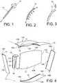
- step A)comprises a first step a) consisting in providing a web 10, and profiled elements 12 each comprising a respective base 14 having a main face 14A, and a respective fin 16A-16D extending projecting from the base 14, on a side opposite to the main face 14A.
- each of the profiled elements 12can advantageously be manufactured by means of a process comprising a step of extruding a material intended to form the element 12, through a die 20 ( figure 1 ) configured to form the base 14 and the fin 16, then a possible step of forming the element 12 ( figure 2 ) allowing to give a bending to the element 12.
- the conformation of the profiled elements 12lends itself well to manufacture by extrusion, which allows the manufacture of sections in one piece at a cost considerably lower than the forging techniques sometimes used for the manufacture of cross-sectional or tee-shaped elements of the same. prior art.
- the method of prior manufacturing of the profiled elements 12may further include a step of machining the element 12 by means of a machining tool 22 ( figure 3 ) possibly making it possible to improve the surface state of the element 12 and, where appropriate, to form orifices through the base 14 and any counterbores around each of the orifices (the orifices and counterbores not being not visible on figures 1-4 ).
- the step of forming the aforementioned orificesis however carried out subsequently, as will appear more clearly in what follows.
- the profiled elementscomprise a first profiled element, said upper section 12A, a second profiled element, said lower section 12B, a third profiled element, said front section 12C, and a fourth profiled element, said rear section 12D.
- the upper 12A and lower 12B sectionsare arranged at two opposite ends of the core 10, namely an upper end 10A and a lower end 10B.
- the front 12C and rear 12D profilesare arranged at two other opposite ends of the web 10, namely a front end 10C and a rear end 10D, which each connect the upper end 10A to the end. lower 10B.
- the base 14 of each of these profiled elementsextends from one end of the corresponding fin 16B-16D.
- These three profiled elementsthus each have a so-called “angled” configuration.
- the expression "angled”is intended to cover a configuration in which the fin 16B-16D is orthogonal, or inclined at an angle greater than 45 degrees, with respect to the main face 14A of the 'base 14.
- the base 14 of the upper section 12Aand in particular the main face 14A thereof, extend on either side of the fin 16A of this upper section, at one end of said fin.
- the base 14 of the upper section 12Acomprises an extension 14B which is inclined with respect to the junction surface 24 extending from an upper end of the corresponding main face 14A, being inclined with respect to this. last, so that the extension 14B and the upper fin 16A form an obtuse angle ⁇ and extend from two opposite sides with respect to the corresponding main face 14A.
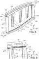
- Step A)then comprises a step b) consisting in fixing the respective bases 14 of the profiled elements 12 to the web 10, so that the respective fins 16A-16D of the profiled elements extend from a first side C1 by in relation to soul 10, as it appears on the figure 5 , and so that the respective bases 14 of the profiled elements 12 and the core 10 together form a main web 39, which has a junction surface 24, preferably continuous, arranged on a second side C2 opposite to the first side C1 , as will become clearer in what follows ( figure 9 ).
- the junction surface 24thus includes the main faces 14A of the bases 14.
- the extension 14B of the base of the upper section 12Atherefore extends from the second side C2.
- the fixing of the bases 14 to the core 10is carried out by edge-to-edge friction stir welding (FSW).
- FSWedge-to-edge friction stir welding
- Step A)also comprises a step c) consisting in providing first angled fittings 28, called internal frame feet, each comprising a respective sole 30 and a heel 32 (one of these internal frame feet being visible on the figure 4 ).
- Each of the feet of internal frames 28further comprises a stiffening web 33 in the form of a ramp.
- step A)comprises a step d) consisting in fixing the respective soles 30 of the feet of internal frames 28 on the main web 39, typically on at least one element among the core 10 and the base 14 of the upper section 12A, so that the respective heels 32 of the feet of internal frames 28 are placed opposite, and preferably in contact, with the fin 16A of the upper section 12A.
- the soles 30are fixed to the core 10.
- the figures 5 and 6show the assembly thus formed at the end of step d).
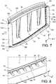
- step A)then comprises a step e) consisting in drilling these orifices 34 through the bases 14 of each of the profiled elements 12 ( figure 7 ), and, preferably, to form countersinks 36 around all or part of the orifices of the profiled elements 12 ( figures 7 and 8 ).
- junction rib 37 obtained at the end of step A)is visible on the figure 9 .
- step A) of manufacturing the junction rib 37may be different from the above description.
- the profiled elements 12can for example be fixed to the core 10 by other means, for example by through fasteners.
- the profiled elements 12 and the core 10can be made in one piece, for example by molding.
- the junction rib 37therefore comprises the main web 39, from which the fins 16A-16D extend on the first side C1, and which defines the junction surface 24 on the second side C2.
- This main web 39corresponds, in the preferred embodiment of the invention described above, to the assembly formed by the core 10 and by the bases 14 of the profiled elements 12.
- the main sail 39comprises, at the end of step A), rows of orifices 34 opening out on the second side C2 into the junction surface, and on the first side C1 (opposite to said surface), these orifices 34 therefore being through.
- the rows of orifices 34comprise at least a first row of orifices R1 formed in an upper part of the main web 39, where appropriate in the base 14 of the upper section 12A, and a second row of orifices R2 formed in a lower part of the main wall 39, where appropriate in the base 14 of the lower section 12B, as shown on the figure 9 .
- the rows R1 and R2extend generally from a front side to a rear side of the junction rib, respectively close to the upper and lower ends of the main web 39.
- the rows of orifices 34further comprise a third row of orifices R3 extending generally from the front side to the rear side of the junction rib and formed in the upper part of the main wall 39, if necessary in the base 14 of the upper section 12A ( figure 9 ), so that the first row of orifices R1 and the third row of orifices R3 are arranged (and open out) respectively on either side of the upper fin 16A.
- the first row R1is thus located between the core 10 and the third row R3 or, more generally, between the second row R2 and the third row R3.
- the rows of orifices 34also include a fourth row of orifices R4 formed in a front part of the main web 39, where appropriate in the base 14 of the front section 12C, and a fifth row of orifices R5 formed in a part rear of the main screen 39, where appropriate in the base 14 of the rear section 12D. Rows R4 and R5 extend generally from a lower side to an upper side of the junction rib, respectively near the front and rear ends of the main web 39.
- the rows R1, R2, R4 and R5are each arranged in a part of the corresponding base 14 by which the corresponding profiled element 12 is fixed to the web 10.
- the aforementioned partcorresponds to the whole of the base 14.
- the aforementioned partis the part 38 of the base 14 located on the side of the core 10 relative to the upper fin 16A.
- extension 14Bextends on the second side C2 from an upper end of the upper part of the main wall 39.
- the fins 16A-16Dare connected to the corresponding bases 14 by respective fillets 40 ( figure 8 ) through which the countersinks 36 are formed.
- Each of the fillets 40has a curvature discontinuity 42 at its connection to the corresponding base 14. Such a curvature discontinuity makes it possible to increase the radius of curvature of the fillet 40 without increasing the extent of the base 14 in the direction orthogonal to the corresponding fin 16A-16D.
- the fillets 40thus have a relatively large thickness, which allows them to play a stiffening role within the profiled elements 12.
- the rows R1, R2, R4 and R5 of orificesare provided with countersinks 36, while the row R3 does not.
- the upper 54A and lower 54B panels and the front 54C and rear 54D side membersthus define an internal space 55 of the central wing box, open at the level of the lateral ends 56 of the central wing box 52 (only one of the lateral ends 56 being visible on figures 9-18 ).
- the upper 54A and lower 54B panelsare provided, on their respective internal faces, with stiffeners 53, in a well known manner.
- the heel 48 of the upper external fitting 44has orifices 58 ( figures 10-11 ) arranged to be respectively aligned with all or part of the orifices 34 of the third row R3.
- the splint 50preferably comprises a proximal part 50A and a distal part 50B inclined with respect to each other, so that in cross section, the upper face of the distal part 50B forms an angle ⁇ with respect to the upper face of the proximal part 50A, the latter upper face typically extending parallel to the X and Y directions.
- the angle ⁇is of course between 90 degrees and 180 degrees excluded, and is preferably greater than 135 degrees.
- the upper external fitting 44 and the fishplate 50are elements each made in a single piece, preferably by extrusion, like the profiled elements 12.
- the upper outer fitting 44is positioned so that the holes 58 of its heel 48 are aligned with the holes of the third row of holes R3 of the upper channel 12A (as shown in figure figure 15 ).
- Step F)also consists in fixing the respective fins 16C, 16D of the front 12C and rear 12D sections to the front 54C and rear 54D side members respectively.
- the figures 12 to 14illustrate the central wing module 64, obtained at the end of step i), and formed of the central wing box 52 and the junction rib 37 assembled together in the manner described above .
- the fasteners 60 and 62are not visible in these figures.
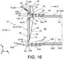
- step I)then comprises a step ii) consisting generally in providing a fuselage structure 66 (partially visible on the figures 15 , 16 and 19 ), and a step iii) generally consisting in fixing the upper external fitting 44 to the fuselage structure 66.
- the fuselage structure 66typically comprises circumferential frames and a skin 70 fixed to the circumferential frames 68.
- the circumferential frames 68integrate (in one piece or by assembly) of the respective third angle brackets 72, called the feet of outer frames, each comprising a respective sole 74 and heel 76, as well as a respective stiffening web 77.
- step iii)comprises fixing the respective heels 76 of the outer frame feet 72 respectively to the respective heels 32 of the inner frame feet 28 by means of third through fasteners 78 ( figure 16 ).
- These members 78jointly pass through the heels 32 and 76, the sole 46 of the upper external fitting 44, and the upper panel 54A of the central wing box 52.
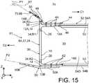
- Step iii)further comprises the fixing of the skin 70 on the extension 14B of the junction rib 37 by means of fourth through fasteners 80 ( figures 15 and 16 ).
- the figures 15 and 16thus show part of the fuselage section 81 obtained at the end of step I).
- the method of manufacturing the aircraftthen comprises a step II) consisting in providing at least one wing 82 comprising a lateral wing box 84 delimiting an internal space 85, and a step III) consisting in positioning one end 86 of the wing.
- side wing box 84in look at the junction surface 24 of the junction rib 37, so that the distal portion 50B of the fishplate 50 is positioned outside the internal space 85 of the wing side box 84.
- the wing side box 84has an upper panel 84A and a lower panel 84B, as well as a front spar (not visible) and a rear spar 84D each connecting the upper panel 84A to the lower panel 84B, in a well known manner.
- the wing side box 84comprises a fourth angled fitting 88 comprising a respective sole 90 and a heel 92, a fifth angled fitting 94 comprising a respective sole 96 and a heel 98, and a sixth angled fitting 100 comprising a sole 102 and a heel 104 respectively.
- the sole 90 of the fourth angled fitting 88is fixed to the upper panel 84A, inside the internal space 85 of the side wing box, while the sole 102 of the sixth angled fitting 100 is fixed to the upper panel 84A outside the internal space 85 of the side wing box.
- the soles 90 and 102are attached to the upper panel 84A jointly, that is to say by means of common fasteners.
- the sole 96 of the fifth angled fitting 94is fixed to the lower panel 84B inside the internal space 85 of the side wing box.
- the respective heels 92, 98 and 104 of the fittings 88, 94 and 100have respective orifices 106, 107 and 108 arranged respectively to be able to be aligned with the orifices 34 of the rows R1, R2 and R3, as will appear more clearly in what will appear in the following text. follows.
- step IIIthe end 86 of the wing wing box is substantially in contact with the junction surface 24.
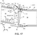
- the method of manufacturing the aircraftthen comprises a step IV) consisting in fixing the lateral wing box 84 to the junction rib 37 by means of fixing members working in tension / compression 110, 112, 114 engaged respectively in the orifices 34 formed in the main sail 39, and also to fix the side wing box 84 to the distal part 50B of the fishplate 50 by means of fifth through fixing members 116.
- the fasteners working in tension / compression 110, 112, 114 and the fifth through fasteners 116are also visible, in the unassembled state, on the figure 17 .
- the fasteners working in tension / compressioncomprise sixth through fasteners 110 mounted jointly through the orifices 106 ( figure 17 ) formed in the heel 92 of the fourth angled fitting 88 and through the orifices 34 of the first row of orifices R1.
- fasteners working in tension / compressioncomprise seventh through fasteners 112 mounted jointly through the orifices 107 ( figure 17 ) formed in the heel 98 of the fifth angled fitting 94 and through the orifices 34 of the second row of orifices R2.
- the fasteners working in tension / compressioncomprise eighth through fasteners 114 mounted jointly through the orifices 108 formed in the heel 104 of the sixth angled fitting 100, through the orifices 34 of the third row of orifices R3, and through the orifices 58 of the heel 48 of the upper external fitting 44.
- the fasteners working in traction / compression 110, 112, 114are bolts.
- the fasteners 60, 62, 78, 80 and 116are preferably also bolts. Those skilled in the art will understand that due to their arrangement, the fasteners 60, 62, 80 and 116 work mainly in shear.
- the extension 14B of the junction rib 37has a face lower (that is to say arranged on the side of the wing 82) which forms, with a horizontal plane XY parallel to the directions X and Y, an angle ⁇ greater than the angle ⁇ formed by the upper face of the part distal 50B of the fishplate 50 with respect to the XY plane ( figure 15 ).
- the plan P1 of the lower face of the extension 14B and the plane P2 of the upper face of the distal part 50Bhave an intersection located on the first side C1 with respect to the junction surface 24.
- the figure 19very schematically illustrates an example of an aircraft 120 obtained at the end of the method according to the invention.
- the methodin its most general definition, relates to only one side of the aircraft (i.e. a wing 82, a junction rib 37 and a corresponding lateral end 56 of the central wing box 52)
- the methodis of course intended to be implemented in a similar manner with regard to the opposite side of the aircraft for the attachment of a second wing 82 'to the fuselage section 81 by means of a second rib junction 37 'arranged at the other lateral end of the central wing box.
- the inventionhas many advantages.
- junction rib 37can be manufactured at an upstream stage of assembly of the aircraft, in parallel with manufacturing operations of the central wing box 52.
- junction rib 37indeed allows its assembly to the central wing box 52 after the latter has been assembled.
- the assembly of the various profiled elements 12 to the core 10 by FSW weldingsaves time and mass and proves to be simpler to implement than assembly by bolting or riveting.
- the methodalso makes it possible to integrate a maximum of elements into the central wing module, and therefore at an upstream stage of assembly of the aircraft, including the upper external fitting 44, the internal frame feet 28 and the splint 50.
- the pre-drilling of the orifices 34also makes it possible to avoid having to carry out these operations at a stage of final assembly of the aircraft.
- the upper external fitting 44can, as a variant, be replaced by a plurality of fittings configured to be juxtaposed along the base 14 of the upper section 14A, with or without spacing between these fittings.
- the third row of orifices R3allows the main web 39 to directly take up the tensile / compressive forces applied to the junction rib 37 by the lateral wing box 84.
Landscapes
- Engineering & Computer Science (AREA)
- Mechanical Engineering (AREA)
- Aviation & Aerospace Engineering (AREA)
- Connection Of Plates (AREA)
- Powder Metallurgy (AREA)
- Automatic Assembly (AREA)
- Escalators And Moving Walkways (AREA)
Description
Translated fromFrenchLa présente invention se rapporte au domaine de la structure des aéronefs, et concerne plus particulièrement une nervure de jonction destinée à la jonction voilure-caisson central de voilure d'un aéronef, un procédé de fabrication d'une telle nervure de jonction, l'utilisation de cette nervure de jonction ou de ce procédé au sein d'un procédé de fabrication d'un module central de voilure pour aéronef, l'utilisation de ce dernier procédé au sein d'un procédé de fabrication d'un tronçon de fuselage pour aéronef, et enfin l'utilisation de ce dernier procédé au sein d'un procédé de fabrication d'un aéronef.The present invention relates to the field of aircraft structure, and relates more particularly to a junction rib intended for the wing-central box junction of the wing of an aircraft, a method of manufacturing such a junction rib, the use of this junction rib or of this method within a method of manufacturing a central wing module for an aircraft, the use of the latter method within a method of manufacturing a fuselage section for aircraft, and finally the use of the latter process within a manufacturing process of an aircraft.
Dans un aéronef comportant un fuselage et une voilure comportant deux ailes symétriques opposées fixées au fuselage, le fuselage intègre en général une structure en forme de caisson, dénommée « caisson central de voilure », sur laquelle sont fixées des structures respectives des ailes, également en forme de caissons et généralement dénommées « caissons latéraux de voilure ».In an aircraft comprising a fuselage and a wing comprising two opposite symmetrical wings fixed to the fuselage, the fuselage generally incorporates a box-shaped structure, called a “central wing box”, on which respective wing structures are fixed, also in box-shaped and generally referred to as "wing side boxes".
Le caisson central de voilure comporte typiquement un panneau supérieur, également dénommé panneau extrados, un panneau inférieur, également dénommé panneau intrados, ainsi qu'un longeron avant et un longeron arrière qui relient chacun le panneau inférieur au panneau supérieur. Le caisson central de voilure intègre en général des nervures internes de rigidification reliant entre eux les panneaux inférieur et supérieur et les longerons avant et arrière.The central wing box typically comprises an upper panel, also called the upper panel, a lower panel, also called the lower surface panel, as well as a front spar and a rear spar which each connect the lower panel to the upper panel. The central wing box generally incorporates internal stiffening ribs interconnecting the lower and upper panels and the front and rear side members.
La jonction de chaque aile au fuselage est assurée par une nervure de jonction jouant le rôle d'interface structurelle entre le caisson latéral de voilure correspondant et le caisson central de voilure.The junction of each wing to the fuselage is provided by a junction rib acting as a structural interface between the corresponding side wing box and the central wing box.
La nervure de jonction comporte en général une âme, et un ensemble d'éléments profilés en croix ou en té agencés en périphérie de l'âme et fixés sur celle-ci au moyen de boulons de cisaillement, comme montré par exemple à la page
Chacun des éléments profilés comporte une ailette ou branche qui est fixée sur un panneau ou longeron correspondant du caisson central de voilure, conjointement avec une ou plusieurs ferrures en équerre, et une autre ailette ou branche qui est fixée sur un panneau ou longeron correspondant du caisson latéral de voilure, conjointement avec une ou plusieurs autres ferrures en équerre. La fixation des ailettes et ferrures aux panneaux et longerons est en général réalisée au moyen de boulons de cisaillementEach of the profiled elements comprises a fin or branch which is fixed to a corresponding panel or spar of the central wing box, together with one or more angled fittings, and another fin or branch which is fixed to a corresponding panel or spar of the box wing side, together with one or more other angled fittings. The fastening of the fins and fittings to the panels and side members is generally carried out by means of shear bolts
L'état de l'art est également illustré par le document
La configuration de ces éléments (nervure et éléments profilés) oblige à ce que les opérations de mise en place et de fixation d'une majeure partie de ces éléments interviennent dans des phases avancées du processus d'assemblage de l'aéronef, notamment dans la phase d'assemblage final au cours de laquelle les ailes sont fixées au fuselage.The configuration of these elements (rib and profiled elements) requires that the operations of positioning and fixing a major part of these elements take place in advanced phases of the aircraft assembly process, in particular in the final assembly phase during which the wings are attached to the fuselage.
Or, la phase d'assemblage final est une phase particulièrement coûteuse au regard de l'ensemble du processus d'assemblage d'un aéronef.However, the final assembly phase is a particularly expensive phase with regard to the entire assembly process of an aircraft.
L'invention a notamment pour but d'apporter une solution simple, économique et efficace à ce problème.The object of the invention is in particular to provide a simple, economical and effective solution to this problem.
Elle propose à cet effet une nervure de jonction destinée à la jonction voilure-caisson central de voilure d'un aéronef, comprenant un voile principal, ainsi qu'une ailette supérieure et une ailette inférieure qui s'étendent à partir du voile principal, d'un premier côté par rapport au voile principal.For this purpose, it proposes a junction rib intended for the wing-central wing box junction of an aircraft, comprising a main wing, as well as an upper fin and a lower fin which extend from the main wing, d 'a first side with respect to the main veil.
Le voile principal présente une surface de jonction agencée d'un deuxième côté opposé au premier côté, le voile principal comportant des rangées d'orifices débouchant du deuxième côté dans la surface de jonction et du premier côté, les rangées d'orifices comprenant au moins une première rangée d'orifices formée dans une partie supérieure du voile principal et s'étendant d'un côté avant vers un côté arrière de la nervure de jonction, et une deuxième rangée d'orifices formée dans une partie inférieure du voile principal et s'étendant du côté avant vers le côté arrière de la nervure de jonction, chacune des rangées d'orifices comprenant des orifices à l'état libre.The main web has a junction surface arranged on a second side opposite to the first side, the main web comprising rows of orifices opening out on the second side into the junction surface and on the first side, the rows of orifices comprising at least a first row of orifices formed in an upper part of the main web and extending from a front side to a rear side of the junction rib, and a second row of holes formed in a lower part of the main web and extending from the front side to the side rear of the junction rib, each of the rows of orifices comprising orifices in the free state.
Par « partie supérieure » et « partie inférieure », il faut comprendre que la partie supérieure s'étend de manière générale au-dessus de la partie inférieure.By “upper part” and “lower part”, it should be understood that the upper part extends generally above the lower part.
Par « orifices à l'état libre », il faut comprendre que les orifices sont inoccupés, c'est-à-dire aptes à recevoir ultérieurement des organes de fixation.By “openings in the free state”, it should be understood that the orifices are unoccupied, that is to say capable of subsequently receiving fixing members.
La nervure de jonction ainsi réalisée permet la jonction d'une aile à un tronçon de fuselage d'aéronef d'une manière particulièrement simple et efficace, permettant en particulier de minimiser le nombre et la complexité des opérations restant à mettre en œuvre au stade d'assemblage final de l'aéronef, comme cela apparaîtra plus clairement dans ce qui suit.The junction rib thus produced allows the junction of a wing to a section of the aircraft fuselage in a particularly simple and efficient manner, in particular making it possible to minimize the number and the complexity of the operations remaining to be carried out at the stage of final assembly of the aircraft, as will appear more clearly in what follows.
De plus, les rangées d'orifices comprennent une troisième rangée d'orifices formée dans la partie supérieure du voile principal et s'étendant du côté avant vers le côté arrière de la nervure de jonction, de sorte que les première et troisième rangées d'orifices sont agencées respectivement de part et d'autre de l'ailette supérieure.In addition, the rows of holes include a third row of holes formed in the upper part of the main web and extending from the front side to the rear side of the junction rib, so that the first and third rows of orifices are respectively arranged on either side of the upper fin.
Le voile principale est ainsi apte à reprendre directement des efforts de traction de ferrures supérieures, comme cela apparaîtra plus clairement dans ce qui suit.The main web is thus able to directly take up the tensile forces of upper fittings, as will appear more clearly in what follows.
De préférence, la nervure de jonction comporte une extension qui est inclinée par rapport à la surface de jonction et qui s'étend du deuxième côté à partir d'une extrémité supérieure de la partie supérieure du voile principal, de manière à former un angle obtus avec l'ailette supérieure en section transversale.Preferably, the junction rib has an extension which is inclined with respect to the junction surface and which extends on the second side from an upper end of the upper part of the main web, so as to form an obtuse angle. with the upper fin in cross section.
De préférence, la nervure de jonction comporte en outre une ailette avant et une ailette arrière qui s'étendent à partir du voile principal, du premier côté par rapport au voile principal, et les rangées d'orifices comprennent en outre une quatrième rangée d'orifices formée dans une partie avant du voile principal et s'étendant d'un côté inférieur vers un côté supérieur de la nervure de jonction, et une cinquième rangée d'orifices formée dans une partie arrière du voile principal et s'étendant du côté inférieur vers le côté supérieur de la nervure de jonction.Preferably, the junction rib further comprises a front fin and a rear fin which extend from the main web, on the first side of the main web, and the rows of orifices further include a fourth row of orifices formed in a front portion of the main web and extending from a lower side to an upper side of the junction rib, and a fifth row of orifices formed in a rear portion of the main web and extending from the lower side towards the upper side of the connecting rib.
L'invention concerne également un procédé de fabrication d'une nervure de jonction du type décrit ci-dessus, comprenant au moins les étapes suivantes :
- a) mettre à disposition une âme, et des éléments profilés comprenant chacun une embase respective et une ailette respective s'étendant en saillie à partir de l'embase ; puis
- b) fixer les embases respectives des éléments profilés à l'âme, de sorte que les ailettes respectives des éléments profilés s'étendent d'un premier côté par rapport à l'âme, correspondant audit premier côté, les embases respectives des éléments profilés et l'âme formant ensemble ledit voile principal ;
- a) providing a core, and profiled elements each comprising a respective base and a respective fin projecting from the base; then
- b) fixing the respective bases of the profiled elements to the web, so that the respective fins of the profiled elements extend on a first side with respect to the web, corresponding to said first side, the respective bases of the profiled elements and the core together forming said main web;
De préférence, chacun des éléments profilés autres que le profilé supérieur présente une configuration en équerre.Preferably, each of the profiled elements other than the upper section has an angled configuration.
De préférence, le procédé comprend en outre les étapes suivantes :
- c) mettre à disposition des premières ferrures en équerre, dites pieds de cadres internes, comprenant chacune une semelle et un talon respectifs ; puis
- d) après l'étape b), fixer les semelles respectives des pieds de cadres internes sur le voile principal.
- c) providing first angled fittings, called internal frame feet, each comprising a respective sole and heel; then
- d) after step b), fix the respective soles of the internal frame feet on the main wall.
Le cas échéant, les rangées d'orifices comprennent en outre avantageusement la quatrième rangée d'orifices, formée dans un troisième des éléments profilés, dit profilé avant, et la cinquième rangée d'orifices, formée dans un quatrième des éléments profilés, dit profilé arrière, les profilés avant et arrière étant agencés à deux extrémités opposées de l'âme, dites extrémité avant et extrémité arrière respectivement, qui relient chacune l'extrémité supérieure à l'extrémité inférieure de l'âme, de sorte que l'embase du profilé avant forme ladite partie avant du voile principal et que l'ailette du profilé avant forme ladite ailette avant, et de sorte que l'embase du profilé arrière forme ladite partie arrière du voile principal et que l'ailette du profilé arrière forme ladite ailette arrière.Where appropriate, the rows of orifices advantageously furthermore comprise the fourth row of orifices, formed in a third of the elements. sections, called the front section, and the fifth row of orifices, formed in a fourth of the profiled elements, called the rear section, the front and rear sections being arranged at two opposite ends of the core, called the front end and the rear end respectively, which each connect the upper end to the lower end of the web, so that the base of the front section forms said front part of the main web and that the fin of the front section forms said front fin, and so that the base of the rear section forms said rear part of the main web and that the fin of the rear section forms said rear fin.
L'invention concerne aussi un procédé de fabrication d'un module central de voilure pour aéronef, comprenant les étapes suivantes :
- A) fabriquer au moins une nervure de jonction du type décrit ci-dessus, éventuellement au moyen du procédé du type décrit ci-dessus ;
- B) mettre à disposition au moins une deuxième ferrure en équerre, dite ferrure externe supérieure, comprenant une semelle et un talon ;
- C) mettre à disposition au moins une éclisse ;
- D) mettre à disposition un caisson central de voilure, comportant au moins un panneau supérieur, un panneau inférieur, un longeron avant reliant une extrémité avant du panneau supérieur à une extrémité avant du panneau inférieur, et un longeron arrière reliant une extrémité arrière du panneau supérieur à une extrémité arrière du panneau inférieur, de sorte que les panneaux supérieur et inférieur et les longerons avant et arrière délimitent un espace interne du caisson central de voilure ouvert en au moins une extrémité latérale du caisson central de voilure ; puis
- E) disposer la nervure de jonction à ladite extrémité latérale du caisson central de voilure, en insérant les ailettes dans l'espace interne du caisson central de voilure, de sorte que l'ailette supérieure soit en regard du panneau supérieur et que l'ailette inférieure soit en regard du panneau inférieur ; puis
- F) fixer conjointement l'ailette supérieure et la semelle de ladite au moins une ferrure externe supérieure au panneau supérieur au moyen de premiers organes de fixation traversants, et fixer conjointement l'ailette inférieure et une partie proximale de ladite au moins une éclisse au panneau inférieur au moyen de deuxièmes organes de fixation traversants, de sorte qu'une partie distale de ladite au moins une éclisse s'étende au-delà de la surface de jonction dans une direction d'éloignement par rapport au caisson central de voilure.
- A) manufacture at least one junction rib of the type described above, optionally by means of the method of the type described above;
- B) providing at least one second angled fitting, called an upper outer fitting, comprising a sole and a heel;
- C) provide at least one fishplate;
- D) provide a central wing box, comprising at least an upper panel, a lower panel, a front spar connecting a front end of the upper panel to a front end of the lower panel, and a rear spar connecting a rear end of the panel upper to a rear end of the lower panel, so that the upper and lower panels and the front and rear side members define an internal space of the central wing box open at at least one side end of the central wing box; then
- E) arrange the junction rib at said lateral end of the central wing box, inserting the fins into the internal space of the central wing box, so that the upper fin is facing the upper panel and the fin lower or opposite the lower panel; then
- F) jointly fixing the upper fin and the sole of said at least one upper external fitting to the upper panel by means of first through fasteners, and jointly fixing the lower fin and a proximal part of said at least one fishplate to the panel lower by means of second organs of through fixing, so that a distal part of said at least one fishplate extends beyond the junction surface in a direction away from the central wing box.
Le cas échéant, l'étape F) comporte en outre avantageusement la fixation des ailettes avant et arrière respectivement aux longerons avant et arrière.Where appropriate, step F) further advantageously comprises the fixing of the front and rear fins respectively to the front and rear side members.
De préférence, la partie distale de ladite au moins une éclisse forme, en section transversale, un angle par rapport à la partie proximale de ladite au moins une éclisse.Preferably, the distal part of said at least one fishplate forms, in cross section, an angle with respect to the proximal part of said at least one fishplate.
Le cas échéant, le talon de ladite au moins une ferrure externe supérieure comporte avantageusement des orifices respectivement alignés avec les orifices de la troisième rangée d'orifices.Where appropriate, the heel of said at least one upper external fitting advantageously comprises orifices respectively aligned with the orifices of the third row of orifices.
L'invention concerne aussi un procédé de fabrication d'un tronçon de fuselage pour aéronef, comprenant les étapes suivantes :
- i) fabriquer un module central de voilure pour aéronef selon un procédé du type décrit ci-dessus ;
- ii) mettre à disposition une structure de fuselage ;
- iii) fixer ladite au moins une ferrure externe supérieure à la structure de fuselage.
- i) manufacturing a central wing module for an aircraft according to a method of the type described above;
- ii) provide a fuselage structure;
- iii) fixing said at least one upper external fitting to the fuselage structure.
Dans des modes de réalisation préférés :
- la structure de fuselage comporte des cadres circonférentiels pourvus de troisièmes ferrures en équerre respectives, dites pieds de cadres externes, comprenant chacune une semelle et un talon respectifs ; et
- l'étape iii) comporte la fixation des talons respectifs des pieds de cadres externes respectivement aux talons respectifs des pieds de cadres internes au moyen de troisièmes organes de fixation traversants.
- the fuselage structure comprises circumferential frames provided with respective third angle brackets, called outer frame feet, each comprising a respective sole and a heel; and
- step iii) comprises fixing the respective heels of the outer frame feet respectively to the respective heels of the inner frame feet by means of third through fasteners.
Dans des modes de réalisation préférés, la structure de fuselage comporte une peau, et l'étape iii) comporte la fixation de la peau sur l'extension au moyen de quatrièmes organes de fixation traversants.In preferred embodiments, the fuselage structure includes a skin, and step iii) includes attaching the skin to the extension by means of fourth through fasteners.
L'invention concerne aussi un procédé de fabrication d'un aéronef, comprenant les étapes consistant à :
- I) fabriquer un tronçon de fuselage selon un procédé du type décrit ci-dessus ;
- II) mettre à disposition au moins une aile comportant un caisson latéral de voilure délimitant un espace interne ; puis
- III) positionner une extrémité du caisson latéral de voilure en regard de la surface de jonction, de sorte que la partie distale de ladite au moins une éclisse soit positionnée à l'extérieur de l'espace interne du caisson latéral de voilure ; puis
- IV) fixer le caisson latéral de voilure à la nervure de jonction au moyen d'organes de fixation travaillant en traction/compression engagés respectivement dans les orifices desdites rangées d'orifices, et fixer le caisson latéral de voilure à la partie distale de ladite au moins une éclisse au moyen de cinquièmes organes de fixation traversants.
- I) manufacturing a fuselage section according to a method of the type described above;
- II) providing at least one wing comprising a lateral wing box delimiting an internal space; then
- III) positioning one end of the lateral wing box opposite the junction surface, so that the distal part of said at least one fishplate is positioned outside the internal space of the lateral wing box; then
- IV) fix the lateral wing box to the junction rib by means of fasteners working in tension / compression engaged respectively in the orifices of said rows of orifices, and fix the lateral wing box to the distal part of said au at least one fishplate by means of fifth through fasteners.
De préférence :
- le caisson latéral de voilure comporte un panneau supérieur et un panneau inférieur, ainsi qu'au moins une quatrième ferrure en équerre et au moins une cinquième ferrure en équerre ;
- lesdites au moins une quatrième et cinquième ferrures en équerre comprennent chacune une semelle et un talon respectifs ;
- la semelle de ladite au moins une quatrième ferrure en équerre est fixée sur le panneau supérieur du caisson latéral de voilure, à l'intérieur de l'espace interne du caisson latéral de voilure ;
- la semelle de ladite au moins une cinquième ferrure en équerre est fixée sur le panneau inférieur du caisson latéral de voilure, à l'intérieur de l'espace interne du caisson latéral de voilure ;
- lesdits organes de fixation travaillant en traction/compression comprennent des sixièmes organes de fixation traversants montés conjointement au travers d'orifices formés dans le talon de ladite au moins une quatrième ferrure en équerre et des orifices de la première rangée d'orifices ; et
- lesdits organes de fixation travaillant en traction/compression comprennent des septièmes organes de fixation traversants montés conjointement au travers d'orifices formés dans le talon de ladite au moins une cinquième ferrure en équerre et des orifices de la deuxième rangée d'orifices.
- the wing side box comprises an upper panel and a lower panel, as well as at least a fourth angled fitting and at least a fifth angled fitting;
- said at least a fourth and fifth angled fittings each comprise a respective sole and a heel;
- the sole of said at least one fourth angled fitting is fixed to the upper panel of the side wing box, inside the internal space of the side wing box;
- the sole of said at least one fifth angled fitting is fixed to the lower panel of the side wing box, inside the internal space of the side wing box;
- said fasteners working in tension / compression comprise sixth through fasteners mounted jointly through orifices formed in the heel of said at least one fourth angled fitting and orifices in the first row of orifices; and
- said fasteners working in tension / compression comprise seventh through fasteners mounted jointly through orifices formed in the heel of said at least one fifth angled fitting and orifices in the second row of orifices.
Dans des modes de réalisation préférés :
- le caisson latéral de voilure comporte au moins une sixième ferrure en équerre comprenant une semelle et un talon ;
- la semelle de ladite au moins une sixième ferrure en équerre est fixée sur le panneau supérieur à l'extérieur de l'espace interne du caisson latéral de voilure ; et
- lesdits organes de fixation travaillant en traction/compression comprennent des huitièmes organes de fixation traversants montés conjointement au travers d'orifices formés dans le talon de ladite au moins une sixième ferrure en équerre, des orifices de la troisième rangée d'orifices, et des orifices du talon de ladite au moins une ferrure externe supérieure.
- the lateral wing box comprises at least a sixth angled fitting comprising a sole and a heel;
- the sole of said at least one sixth angled fitting is fixed to the upper panel outside the internal space of the lateral wing box; and
- said fasteners working in tension / compression comprise eighth through fasteners mounted jointly through orifices formed in the heel of said at least one sixth angled fitting, orifices in the third row of orifices, and orifices of the heel of said at least one upper outer fitting.
L'invention sera mieux comprise, et d'autres détails, avantages et caractéristiques de celle-ci apparaîtront à la lecture de la description suivante faite à titre d'exemple non limitatif et en référence aux dessins annexés dans lesquels :
- les
figures 1 à 3 sont des vues schématiques en perspective d'un élément profilé destiné à la fabrication d'une nervure de jonction, au cours d'étapes successives de fabrication de l'élément profilé ; - la
figure 4 est une vue schématique en perspective d'éléments destinés à la fabrication de la nervure de jonction ; - la
figure 5 est une vue schématique en perspective des composants de lafigure 4 assemblés pour former la nervure de jonction ; - la
figure 6 est une vue agrandie d'une partie de lafigure 5 ; - la
figure 7 est une vue semblable à lafigure 5 , illustrant la nervure de jonction à un stade ultérieur de sa fabrication ; - la
figure 8 est une vue agrandie d'une partie de lafigure 7 ; - la
figure 9 est une vue semblable à lafigure 7 mais sous un autre angle ; - les
figures 10 et11 sont des vues schématiques, respectivement en coupe transversale et en perspective, de la nervure de jonction et d'autres éléments destinés à la fabrication d'un module central de voilure ; - la
figure 12 est une vue schématique partielle en perspective du module central de voilure formé par l'assemblage des éléments desfigures 10 et11 ; - les
figures 13 et 14 sont des vues agrandies de parties de lafigure 12 ; - les
figures 15 et16 sont des vues schématiques partielles en coupe transversale d'un tronçon de fuselage pour aéronef intégrant le module central de voilure de lafigure 12 ; - la
figure 17 est une vue schématique partielle en coupe transversale du tronçon de fuselage et d'une aile ; - la
figure 18 est une vue semblable à lafigure 17 , illustrant l'aile assemblée au tronçon de fuselage ; - la
figure 19 est une vue schématique en perspective d'un aéronef comprenant l'aile et le tronçon de fuselage de lafigure 18 ; - la
figure 20 est un organigramme d'un procédé de fabrication d'aéronef selon un mode de réalisation préféré de l'invention.
- the
figures 1 to 3 are schematic perspective views of a profiled element intended for the manufacture of a junction rib, during successive stages of manufacture of the profiled element; - the
figure 4 is a schematic perspective view of elements intended for the manufacture of the junction rib; - the
figure 5 is a schematic perspective view of the components of thefigure 4 assembled to form the junction rib; - the
figure 6 is an enlarged view of part of thefigure 5 ; - the
figure 7 is a view similar to thefigure 5 , illustrating the junction rib at a later stage in its manufacture; - the
figure 8 is an enlarged view of part of thefigure 7 ; - the
figure 9 is a view similar to thefigure 7 but from another angle; - the
figures 10 and11 are schematic views, respectively in cross section and in perspective, of the junction rib and other elements intended for the manufacture of a central wing module; - the
figure 12 is a partial schematic perspective view of the central wing module formed by the assembly of the elements of thefigures 10 and11 ; - the
figures 13 and 14 are enlarged views of parts of thefigure 12 ; - the
figures 15 and16 are partial schematic views in cross section of a fuselage section for an aircraft incorporating the central wing module of thefigure 12 ; - the
figure 17 is a partial schematic view in cross section of the fuselage section and a wing; - the
figure 18 is a view similar to thefigure 17 , illustrating the wing assembled to the fuselage section; - the
figure 19 is a schematic perspective view of an aircraft comprising the wing and the fuselage section of thefigure 18 ; - the
figure 20 is a flowchart of an aircraft manufacturing method according to a preferred embodiment of the invention.
Une nervure de jonction destinée à la jonction voilure-caisson central de voilure d'un aéronef selon un mode de réalisation préféré de l'invention, et un procédé de fabrication d'un aéronef selon un mode de réalisation préféré de l'invention, mettant à profit des avantages procurés par ladite nervure de jonction, vont maintenant être décrits en référence aux
Dans la description qui suit, les directions X, Y et Z sont définies par référence à l'orientation des éléments au sein de l'aéronef au terme du procédé de fabrication de ce dernier. La direction longitudinale X est définie conventionnellement comme étant parallèle à l'axe de roulis de l'aéronef, la direction transversale Y comme étant parallèle à l'axe de tangage de l'aéronef, et la direction verticale Z comme étant parallèle à l'axe de lacet de l'aéronef.In the description which follows, the directions X, Y and Z are defined by reference to the orientation of the elements within the aircraft at the end of the manufacturing process of the latter. The longitudinal direction X is conventionally defined as being parallel to the roll axis of the aircraft, the transverse direction Y as being parallel to the pitch axis of the aircraft, and the vertical direction Z as being parallel to the aircraft. yaw axis of the aircraft.
Le procédé de fabrication de l'aéronef comporte d'abord une étape I) consistant à fabriquer un tronçon de fuselage.The aircraft manufacturing process firstly comprises a step I) consisting in manufacturing a fuselage section.
L'étape I) comporte elle-même une étape i) consistant à fabriquer un module central de voilure.Step I) itself comprises a step i) consisting in manufacturing a central wing module.
L'étape i) comporte une étape A) qui consiste à fabriquer au moins une nervure de jonction, et qui va maintenant être décrite en détail.Step i) comprises a step A) which consists in manufacturing at least one junction rib, and which will now be described in detail.
À titre d'exemple, la nervure de jonction considérée est destinée à équiper le côté droit de l'aéronef.By way of example, the junction rib considered is intended to equip the right side of the aircraft.
En référence à la
En référence aux
La conformation des éléments profilés 12 se prête bien à une fabrication par extrusion, qui permet la fabrication de profilés d'un seul tenant à un coût considérablement inférieur aux techniques de forgeage utilisées parfois pour la fabrication des éléments profilés en croix ou en té de l'art antérieur.The conformation of the profiled
Le procédé de fabrication préalable des éléments profilés 12 peut en outre comporter une étape d'usinage de l'élément 12 au moyen d'un outil d'usinage 22 (
Comme le montre la
Les profilés supérieur 12A et inférieur 12B sont agencés au niveau de deux extrémités opposées de l'âme 10, à savoir une extrémité supérieure 10A et une extrémité inférieure 10B. De manière analogue, les profilés avant 12C et arrière 12D sont agencés au niveau de deux autres extrémités opposées de l'âme 10, à savoir une extrémité avant 10C et une extrémité arrière 10D, qui relient chacune l'extrémité supérieure 10A à l'extrémité inférieure 10B.The upper 12A and lower 12B sections are arranged at two opposite ends of the core 10, namely an
Chaque élément, parmi le profilé inférieur 12B, le profilé avant 12C, et le profilé arrière 12D, est intégralement constitué par son embase 14 respective et son ailette 16B-16D respective. De plus, l'embase 14 de chacun de ces éléments profilés s'étend à partir d'une extrémité de l'ailette 16B-16D correspondante. Ces trois éléments profilés présentent ainsi chacun une configuration dite « en équerre ». Dans la terminologie de la présente invention, l'expression « en équerre » entend couvrir une configuration dans laquelle l'ailette 16B-16D est orthogonale, ou inclinée d'un angle supérieur à 45 degrés, par rapport à la face principale 14A de l'embase 14.Each element, among the
En revanche, l'embase 14 du profilé supérieur 12A, et en particulier la face principale 14A de celle-ci, s'étendent de part et d'autre de l'ailette 16A de ce profilé supérieur, à une extrémité de ladite ailette.On the other hand, the
De plus, l'embase 14 du profilé supérieur 12A comporte une extension 14B qui est inclinée par rapport à la surface de jonction 24 s'étendant à partir d'une extrémité supérieure de la face principale 14A correspondante, en étant inclinée par rapport à cette dernière, de sorte que l'extension 14B et l'ailette supérieure 16A forment un angle obtus Ω et s'étendent de deux côtés opposés par rapport à la face principale 14A correspondante.In addition, the
L'étape A) comporte ensuite une étape b) consistant à fixer les embases respectives 14 des éléments profilés 12 à l'âme 10, de sorte que les ailettes respectives 16A-16D des éléments profilés s'étendent d'un premier côté C1 par rapport à l'âme 10, comme cela apparaît sur la
Dans le mode de réalisation préféré de l'invention, la fixation des embases 14 à l'âme 10 est réalisée par soudage par friction malaxage (FSW) bord-à-bord. La
L'étape A) comprend par ailleurs une étape c) consistant à mettre à disposition des premières ferrures en équerre 28, dites pieds de cadres internes, comprenant chacune une semelle 30 et un talon 32 respectifs (l'un de ces pieds de cadres internes étant visible sur la
Après les étapes b) et c), l'étape A) comporte une étape d) consistant à fixer les semelles 30 respectives des pieds de cadres internes 28 sur le voile principal 39, typiquement sur au moins un élément parmi l'âme 10 et l'embase 14 du profilé supérieur 12A, de sorte que les talons 32 respectifs des pieds de cadres internes 28 soient disposés en regard, et de préférence au contact, de l'ailette 16A du profilé supérieur 12A. Dans l'exemple illustré, les semelles 30 sont fixées sur l'âme 10. Les
Dans le cas où les orifices précités n'ont pas été formés préalablement, l'étape A) comporte ensuite une étape e) consistant à percer ces orifices 34 au travers des embases 14 de chacun des éléments profilés 12 (
La nervure de jonction 37 obtenue au terme de l'étape A) est visible sur la
Il est à noter que l'étape A) de fabrication de la nervure de jonction 37 peut être différente de la description qui précède. Les éléments profilés 12 peuvent par exemple être fixés à l'âme 10 par d'autres moyens, par exemple par des organes de fixation traversants. Dans d'autres modes de réalisation, les éléments profilés 12 et l'âme 10 peuvent être réalisés d'un seul tenant, par exemple par moulage.It should be noted that step A) of manufacturing the
Indépendamment de son mode de fabrication, la nervure de jonction 37 comporte donc le voile principal 39, à partir duquel les ailettes 16A-16D s'étendent du premier côté C1, et qui définit la surface de jonction 24 du deuxième côté C2. Ce voile principal 39 correspond, dans le mode de réalisation préféré de l'invention décrit ci-dessus, à l'ensemble formé par l'âme 10 et par les embases 14 des éléments profilés 12.Independently of its mode of manufacture, the
Dans tous les cas, la voile principal 39 comporte, au terme de l'étape A), des rangées d'orifices 34 débouchant du deuxième côté C2 dans la surface de jonction, et du premier côté C1 (opposé à ladite surface), ces orifices 34 étant donc traversants.In all cases, the
Les rangées d'orifices 34 comprennent au moins une première rangée d'orifices R1 formée dans une partie supérieure du voile principal 39, le cas échéant dans l'embase 14 du profilé supérieur 12A, et une deuxième rangée d'orifices R2 formée dans une partie inférieure du voile principal 39, le cas échéant dans l'embase 14 du profilé inférieur 12B, comme cela apparaît sur la
Le cas échéant, certains des orifices de la première rangée R1 sont alignés avec des orifices formés dans les semelles 30 respectives des pieds de cadres internes 28, comme cela apparaîtra plus clairement dans ce qui suit (
Dans le mode de réalisation préféré de l'invention, les rangées d'orifices 34 comprennent en outre une troisième rangée d'orifices R3 s'étendent globalement du côté avant vers le côté arrière de la nervure de jonction et formée dans la partie supérieure du voile principal 39, le cas échéant dans l'embase 14 du profilé supérieur 12A (
Les rangées d'orifices 34 comprennent également une quatrième rangée d'orifices R4 formée dans une partie avant du voile principal 39, le cas échéant dans l'embase 14 du profilé avant 12C, et une cinquième rangée d'orifices R5 formée dans une partie arrière du voile principal 39, le cas échéant dans l'embase 14 du profilé arrière 12D. Les rangées R4 et R5 s'étendent globalement d'un côté inférieur vers un côté supérieur de la nervure de jonction, à proximité respectivement d'extrémités avant et arrière du voile principal 39.The rows of
Les rangées R1, R2, R4 et R5 sont agencées chacune dans une partie de l'embase 14 correspondante par laquelle l'élément profilé 12 correspondant est fixé à l'âme 10. Dans le cas des profilés inférieur 12B, avant 12C et arrière 12D, la partie précitée correspond à l'intégralité de l'embase 14. Dans le cas du profilé supérieur 12A, la partie précitée est la partie 38 de l'embase 14 situé du côté de l'âme 10 par rapport à l'ailette supérieure 16A.The rows R1, R2, R4 and R5 are each arranged in a part of the
Le cas échéant, l'extension 14B s'étend du deuxième côté C2 à partir d'une extrémité supérieure de la partie supérieure du voile principal 39.Where appropriate, the
Dans le mode de réalisation préféré de l'invention, les ailettes 16A-16D sont raccordées aux embases 14 correspondantes par des congés 40 respectifs (
Dans le mode de réalisation préféré de l'invention, les rangées R1, R2, R4 et R5 d'orifices sont pourvues de lamages 36, tandis que la rangée R3 en est dépourvue.In the preferred embodiment of the invention, the rows R1, R2, R4 and R5 of orifices are provided with
Dans tous les cas, il est à noter que la plupart - ou de préférence la totalité - des orifices 34 est à l'état libre, au terme de l'étape A) du procédé. Il faut comprendre par-là que, dans le cas où certains des orifices 34 sont alignés avec des orifices formés dans les semelles 30 respectives des pieds de cadres internes 28, lesdits orifices 34 peuvent être traversés par des organes de fixation provisoire assurant la fixation des semelles 30 sur le voile principal 39. Les autres orifices 34 sont néanmoins à l'état libre, c'est-à-dire inoccupés et donc aptes à recevoir ultérieurement des organes de fixation. Dans le cas où aucun des orifices 34 n'est utilisé pour la fixation des semelles 30 sur le voile principal 39, l'ensemble des orifices 34 est à l'état libre. Dans tous les cas, il est clair que les orifices 34 à l'état libre ne concourent pas à la fixation des éléments profilés 12 sur l'âme 10, ou plus généralement à l'assemblage mutuel d'éléments constituant la nervure de jonction 37.In all cases, it should be noted that most - or preferably all - of the
En référence aux
- une étape B) consistant à mettre à disposition une deuxième ferrure en équerre 44, dite ferrure externe supérieure, comprenant une semelle 46 et
un talon 48 respectifs, - une étape C) consistant à mettre à
disposition une éclisse 50, et - une étape D) consistant à mettre à disposition un caisson central de voilure 52, comportant au moins un panneau supérieur 54A, un panneau inférieur 54B, un longeron avant 54C reliant une extrémité avant du panneau supérieur à une extrémité avant du panneau inférieur, et
un longeron arrière 54D reliant une extrémité arrière du panneau supérieur à une extrémité arrière du panneau inférieur.
- a step B) consisting in providing a second angled fitting 44, called an upper outer fitting, comprising a sole 46 and a
respective heel 48, - a step C) consisting in providing a
fishplate 50, and - a step D) consisting in providing a
central wing box 52, comprising at least anupper panel 54A, alower panel 54B, afront spar 54C connecting a front end of the upper panel to a front end of the lower panel, and arear spar 54D connecting a rear end of the upper panel to a rear end of the lower panel.
Les panneaux supérieur 54A et inférieur 54B et les longerons avant 54C et arrière 54D délimitent ainsi un espace interne 55 du caisson central de voilure, ouvert au niveau des extrémités latérales 56 du caisson central de voilure 52 (l'une seulement des extrémités latérales 56 étant visible sur les
Les panneaux supérieur 54A et inférieur 54B sont pourvus, sur leurs faces internes respectives, de raidisseurs 53, d'une manière bien connue.The upper 54A and lower 54B panels are provided, on their respective internal faces, with
Le talon 48 de la ferrure externe supérieure 44 comporte des orifices 58 (
L'éclisse 50 comporte de préférence une partie proximale 50A et une partie distale 50B inclinées l'une par rapport à l'autre, de sorte qu'en section transversale, la face supérieure de la partie distale 50B forme un angle θ par rapport à la face supérieure de la partie proximale 50A, cette dernière face supérieure s'étendant typiquement parallèlement aux directions X et Y. L'angle θ est bien entendu compris entre 90 degrés et 180 degrés exclus, et est de préférence supérieur à 135 degrés.The
Dans le mode de réalisation préféré de l'invention, la ferrure externe supérieure 44 et l'éclisse 50 sont des éléments réalisés chacun d'un seul tenant, de préférence par extrusion, à l'instar des éléments profilés 12.In the preferred embodiment of the invention, the upper
En référence aux
- une étape E) consistant à disposer la nervure de jonction 37 à une extrémité latérale 56 du caisson central de voilure (visible sur la
figure 11 ), en insérant les ailettes 16A-16D dans l'espace interne du caisson central de voilure 52, de sorte que l'ailette supérieure 16A soit en regard, et sensiblement au contact, du panneau supérieur 54A et que l'ailette inférieure 16B soit en regard, et sensiblement au contact, du panneau inférieur 54B, puis - une étape F) consistant notamment à fixer conjointement l'ailette supérieure 16A et la semelle 46 de la ferrure externe supérieure 44 au panneau supérieur 54A au moyen de premiers organes de fixation traversants 60 (visibles sur la
figure 10 ), et fixer conjointement l'ailette inférieure 16B et la partie proximale 50A de l'éclisse 50 au panneau inférieur 54B au moyen de deuxièmes organes de fixation traversants 62 (figure 10 ), de sorte que la partie distale 50B de l'éclisse 50 s'étende au-delà de la surface de jonction 24, dans une direction d'éloignement par rapport au caisson central de voilure 52, qui correspond à la direction allant du premier côté C1 vers le deuxième côté C2.
- a step E) consisting in placing the
junction rib 37 at alateral end 56 of the central wing box (visible on thefigure 11 ), by inserting thefins 16A-16D into the internal space of thecentral wing box 52, so that theupper fin 16A is facing, and substantially in contact with, theupper panel 54A and that thelower fin 16B is facing, and substantially in contact with, thelower panel 54B, then - a step F) consisting in particular in jointly fixing the
upper fin 16A and the sole 46 of the upperexternal fitting 44 to theupper panel 54A by means of first through fasteners 60 (visible on thefigure 10 ), and jointly fix thelower fin 16B and theproximal part 50A of thefishplate 50 to thelower panel 54B by means of second through fasteners 62 (figure 10 ), so that thedistal portion 50B of thefishplate 50 extends beyond thejunction surface 24, in a direction away from thecentral wing box 52, which corresponds to the direction from the first side C1 to the second side C2.
La ferrure externe supérieure 44 est positionnée de sorte que les orifices 58 de son talon 48 soient alignés avec les orifices de la troisième rangée d'orifices R3 du profilé supérieur 12A (comme cela apparaît sur la
L'étape F) consiste également à fixer les ailettes 16C, 16D respectives des profilés avant 12C et arrière 12D aux longerons avant 54C et arrière 54D respectivement.Step F) also consists in fixing the
Les
En référence aux
Plus précisément, la structure de fuselage 66 comporte typiquement des cadres circonférentiels et une peau 70 fixée sur les cadres circonférentiels 68. Les cadres circonférentiels 68 intègrent (d'un seul tenant ou par assemblage) des troisièmes ferrures en équerre respectives 72, dites pieds de cadres externes, comprenant chacune une semelle 74 et un talon 76 respectifs, ainsi qu'un voile de raidissement 77 respectif.More precisely, the fuselage structure 66 typically comprises circumferential frames and a
Dans ce cas, l'étape iii) comporte la fixation des talons 76 respectifs des pieds de cadres externes 72 respectivement aux talons 32 respectifs des pieds de cadres internes 28 au moyen de troisièmes organes de fixation traversants 78 (
L'étape iii) comporte en outre la fixation de la peau 70 sur l'extension 14B de la nervure de jonction 37 au moyen de quatrièmes organes de fixation traversants 80 (
Les
En référence aux
Le caisson latéral de voilure 84 comporte un panneau supérieur 84A et un panneau inférieur 84B, ainsi qu'un longeron avant (non visible) et un longeron arrière 84D reliant chacun le panneau supérieur 84A au panneau inférieur 84B, d'une manière bien connue.The
De plus, le caisson latéral de voilure 84 comporte une quatrième ferrure en équerre 88 comprenant une semelle 90 et un talon 92 respectifs, une cinquième ferrure en équerre 94 comprenant une semelle 96 et un talon 98 respectifs, et une sixième ferrure en équerre 100 comprenant une semelle 102 et un talon 104 respectifs.In addition, the
La semelle 90 de la quatrième ferrure en équerre 88 est fixée sur le panneau supérieur 84A, à l'intérieur de l'espace interne 85 du caisson latéral de voilure, tandis que la semelle 102 de la sixième ferrure en équerre 100 est fixée sur le panneau supérieur 84A à l'extérieur de l'espace interne 85 du caisson latéral de voilure. Dans l'exemple illustré, les semelles 90 et 102 sont fixées au panneau supérieur 84A de manière conjointe, c'est-à-dire au moyen d'organes de fixation communs.The sole 90 of the fourth angled fitting 88 is fixed to the
De plus, la semelle 96 de la cinquième ferrure en équerre 94 est fixée sur le panneau inférieur 84B à l'intérieur de l'espace interne 85 du caisson latéral de voilure.In addition, the sole 96 of the fifth angled fitting 94 is fixed to the
Les talons respectifs 92, 98 et 104 des ferrures 88, 94 et 100 comportent des orifices respectifs 106, 107 et 108 agencés respectivement pour pouvoir être alignés avec les orifices 34 des rangées R1, R2 et R3, comme cela apparaîtra plus clairement dans ce qui suit.The
Au terme de l'étape III), l'extrémité 86 du caisson latéral de voilure se trouve sensiblement au contact de la surface de jonction 24.At the end of step III), the
En référence aux
Dans le mode de réalisation préféré de l'invention, les organes de fixation travaillant en traction/compression comprennent des sixièmes organes de fixation traversants 110 montés conjointement au travers des orifices 106 (
De plus, les organes de fixation travaillant en traction/compression comprennent des septièmes organes de fixation traversants 112 montés conjointement au travers des orifices 107 (
Enfin, les organes de fixation travaillant en traction/compression comprennent des huitièmes organes de fixation traversants 114 montés conjointement au travers des orifices 108 formés dans le talon 104 de la sixième ferrure en équerre 100, au travers des orifices 34 de la troisième rangée d'orifices R3, et au travers des orifices 58 du talon 48 de la ferrure externe supérieure 44.Finally, the fasteners working in tension / compression comprise eighth through
De manière préférentielle, les organes de fixation travaillant en traction/compression 110, 112, 114 sont des boulons. Les organes de fixation 60, 62, 78, 80 et 116 sont de préférence également des boulons. L'homme du métier comprendra que du fait de leur agencement, les organes de fixation 60, 62, 80 et 116 travaillent principalement en cisaillement.Preferably, the fasteners working in traction /
L'amenée de l'aile 82 au contact de la surface de jonction 24 est rendu possible par le fait que, dans tout plan de section transversale du module central de voilure 81, l'extension 14B de la nervure de jonction 37 présente une face inférieure (c'est-à-dire agencée du côté de l'aile 82) qui forme, avec un plan horizontal XY parallèle aux directions X et Y, un angle α supérieur à l'angle θ que fait la face supérieure de la partie distale 50B de l'éclisse 50 par rapport au plan XY (
La
Bien que le procédé, dans sa définition la plus générale, concerne un seul côté de l'aéronef (c'est-à-dire une aile 82, une nervure de jonction 37 et une extrémité latérale 56 correspondante du caisson central de voilure 52), le procédé est bien entendu prévu pour être mis en œuvre de manière analogue en ce qui concerne le côté opposé de l'aéronef pour la fixation d'une seconde aile 82' au tronçon de fuselage 81 par l'intermédiaire d'une seconde nervure de jonction 37' agencée à l'autre extrémité latérale du caisson central de voilure.Although the method, in its most general definition, relates to only one side of the aircraft (i.e. a
L'invention présente de nombreux avantages.The invention has many advantages.
Premièrement, la nervure de jonction 37 peut être fabriquée à un stade amont d'assemblage de l'aéronef, en parallèle à des opérations de fabrication du caisson central de voilure 52.First, the
La configuration de la nervure de jonction 37 permet en effet son assemblage au caisson central de voilure 52 après que ce dernier a été assemblé.The configuration of the
Le cas échéant, l'assemblage des différents éléments profilés 12 à l'âme 10 par soudage FSW permet un gain de temps et de masse et s'avère plus simple à mettre en œuvre qu'un assemblage par boulonnage ou rivetage.Where appropriate, the assembly of the various profiled
Le procédé permet en outre d'intégrer un maximum d'éléments au module central de voilure, et donc à un stade amont d'assemblage de l'aéronef, y compris la ferrure externe supérieure 44, les pieds de cadres internes 28 et l'éclisse 50.The method also makes it possible to integrate a maximum of elements into the central wing module, and therefore at an upstream stage of assembly of the aircraft, including the upper
Le pré-perçage des orifices 34 permet également d'éviter d'avoir à conduire ces opérations à un stade d'assemblage final de l'aéronef.The pre-drilling of the
L'utilisation d'organes de fixation travaillant en traction/compression 110, 112, 114, en combinaison avec la configuration générale de la nervure de jonction 37, permet de réduire au mieux le nombre et la complexité des opérations au stade d'assemblage final de l'aéronef.The use of fasteners working in tension /
Il est à noter que la ferrure externe supérieure 44 peut, en variante, être remplacée par une pluralité de ferrures configurées pour être juxtaposées le long de l'embase 14 du profilé supérieur 14A, avec ou sans espacement entre ces ferrures. Il en est de même en ce qui concerne les ferrures en équerre 88, 94, 100 du caisson latéral de voilure 84.It should be noted that the upper
Dans tous les cas, la troisième rangée d'orifices R3 permet que le voile principal 39 reprenne directement les efforts de traction/compression appliqués à la nervure de jonction 37 par le caisson latéral de voilure 84.In all cases, the third row of orifices R3 allows the
Claims (17)
- A junction rib (37) designed for the wing-central wingbox junction of an aircraft, comprising a main web (39) and an upper flange (16A) and a lower flange (16B) that extend from the main web (39) on a first side (C1) relative to the main web (39), wherein the main web (39) has a junction surface (24) arranged on a second side (C2) opposite the first side, the main web (39) including rows of orifices (34) opening on the second side (C2) in the junction surface and on the first side (C1) and each comprising orifices in a free state, the rows of orifices comprising at least a first row of orifices (R1) formed in an upper portion of the main web (39) and extending from a front side towards a rear side of the junction rib, a second row of orifices (R2) formed in a lower portion of the main web (39) and extending from the front side towards the rear side of the junction rib, the rows of orifices (34) including a third row of orifices (R3) formed in the upper portion of the main web (39) and extending from the front side towards the rear side of the junction rib such that the first and third rows of orifices (R1, R3) are arranged respectively on either side of the upper flange (16A).
- The junction rib as claimed in claim 1, including an extension (14B) which is inclined relative to the junction surface (24) and which extends on the second side (C2), from an upper end of the upper portion of the main web (39), so as to form an obtuse angle with the upper flange (16A) in cross section.
- The junction rib as claimed in either of claims 1 and 2, furthermore including a front flange (16C) and a rear flange (16D) that extend from the main web (39), on the first side (C1) relative to the main web (39), and wherein the rows of orifices (34) furthermore comprise a fourth row (R4) of orifices formed in a front portion of the main web (39) and extending from a lower side towards an upper side of the junction rib, and a fifth row (R5) of orifices formed in a rear portion of the main web (39) and extending from the lower side to the upper side of the junction rib.
- A method for producing a rib junction (37) as claimed in any one of claims 1 to 3, comprising at least steps of:a) providing a core (10), and profile elements (12) each comprising a respective base (14) and a respective flange (16A-16D) extending to protrude from the base; thenb) fastening the respective bases (14) of the profile elements (12) to the core (10), such that the respective flanges (16A-16D) of the profile elements extend on a first side relative to the core, corresponding to said first side (C1), the respective bases (14) of the profile elements and the core (10) together forming said main web (39);and wherein, on completion of the method, the main web (39) includes the rows of orifices (34) comprising at least said first row of orifices (R1), formed in the base (14) of a first one of the profile elements, called upper profile (12A), and said second row of orifices (R2), formed in the base (14) of a second one of the profile elements, called lower profile (12B), the upper and lower profiles being arranged at two opposite ends of the core, called upper end (10A) and lower end (10B), such that the base (14) of the upper profile (12A) forms said upper portion of the main web (39) and such that the flange of the upper profile (12A) forms said upper flange (16A), and such that the base (14) of the lower profile (12B) forms said lower portion of the main web (39) and such that the flange of the lower profile (12B) forms said lower flange (16B), wherein the base (14) of the upper profile (12A) extends on either side of the flange (16A) of the upper profile and comprises the third row of orifices (R3), and wherein each row of orifices (34) comprises orifices in a free state.
- The method as claimed in claim 4, wherein each of the profile elements (12B, 12C, 12D) other than the upper profile (12A) has an angled configuration
- The method as claimed in either one of claims 4 and 5, furthermore comprising steps of:c) providing first angle fittings, called inner frame supports (28), each comprising a respective base (30) and a shoulder (32); thend) after the step b), fastening the respective bases (30) of the inner frame supports (28) to the main web (39).
- The method as claimed in any one of claims 4 to 6 for producing a rib junction (37) as claimed in claim 3, wherein the rows of orifices (34) furthermore comprise the fourth row of orifices (R4), formed in a third one of the profile elements, called front profile (12C), and the fifth row of orifices (R5), formed in a fourth one of the profile elements, called rear profile (12D), the front and rear profiles being arranged at two opposite ends of the core (10), respectively called front end (10C) and rear end (10D), each of which links the upper end (10A) to the lower end (10B) of the core, such that the base (14) of the front profile (12C) forms said front portion of the main web (39) and such that the flange (16C) of the front profile forms said front flange (16C), and such that the base (14) of the rear profile (12D) forms said rear portion of the main web (39) and such that the flange of the rear profile (12D) forms said rear flange (16D).
- A method for producing a central wing module (64) for aircraft, comprising at least steps of:A) producing at least one junction rib (37) as claimed in any one of claims 1 to 3, potentially by means of the method as claimed in any one of claims 4 to 7;B) providing at least one second angle fitting, called upper outer fitting (44), comprising a base (46) and a shoulder (48);C) providing at least one strap (50);D) providing a central wingbox (52), including at least an upper panel (54A), a lower panel (54B), a front member (54C) linking a front end of the upper panel to a front end of the lower panel, and a rear member (54D) linking a rear end of the upper panel to a rear end of the lower panel, such that the upper and lower panels and the front and rear members delimit an inner space (55) of the central wingbox (52) open at at least one lateral end (56) of the central wingbox, thenE) disposing the junction rib (37) at said lateral end (56) of the central wingbox by inserting the flanges (16A-16D) into the inner space (55) of the central wingbox, such that the upper flange (16A) is facing the upper panel (54A) and the lower flange (16B) is facing the lower panel (54B); thenF) fastening together the upper flange (16A) and the base (46) of said at least one upper outer fitting (44) to the upper panel (54A) using first through-mounted fastening components (60), and fastening together the lower flange (16B) and a proximal portion (50A) of said at least one strap (50) to the lower panel (54B) using second through-mounted fastening components (62), such that a distal portion (50B) of said at least one strap (50) extends beyond the junction surface (24) in a distancing direction relative to the central wingbox (52).
- The method as claimed in claim 8, wherein the junction rib (37) conforms to claim 3, or wherein the step A) consists of producing the junction rib (37) according to the method of claim 7, and wherein the step F) furthermore includes fastening the front flange (16C) and rear flange (16D) respectively to the front member (54C) and the rear member (54D).
- The method as claimed in claim 8 or 9, wherein the distal portion (50B) of said at least one strap (50) forms, in cross section, an angle (θ) relative to the proximal portion (50A) of said at least one strap.
- The method as claimed in any one of claims 8 to 10, wherein the junction rib (37) conforms to claim 2 or wherein the step A) consists of producing the rib junction (37) according to the method of claim 6, and wherein the shoulder (48) of said at least one upper outer fitting (44) includes orifices (58) aligned respectively with the orifices (34) of the third row of orifices (R3).
- A method for producing a fuselage section (81) for aircraft, comprising at least steps of:i) producing a central wing module (64) for aircraft according to the method of any one of claims 8 to 11;ii) providing a fuselage structure (66);iii) fastening said at least one upper outer fitting (44) to the fuselage structure (66).
- The method as claimed in claim 12, wherein:- the step A) of the step i) consists of producing the junction rib (37) according to the method of claim 6;- the fuselage structure (66) includes circumferential frames provided with third respective angle fittings, called outer frame supports (72), each comprising a respective base (74) and a shoulder (76); and- the step iii) includes fastening the respective shoulders (76) of the outer frame supports (72) respectively to the respective shoulders (32) of the inner frame supports (28) using third through-mounted fastening components (78).
- The method as claimed in claim 12 or 13, wherein:- the junction rib (37) conforms to claim 2;- the fuselage structure (66) includes a skin (70); and- the step iii) includes fastening the skin (70) to the extension (14B) using fourth through-mounted fastening components (80).
- A method for producing an aircraft (120), comprising at least steps of:I) producing a fuselage section (81) according to the method of any one of claims 12 to 14;II) providing at least one wing (82) including a lateral wing box (84) delimiting an inner space (85); thenIII) positioning an end (86) of the lateral wingbox (84) to face the junction surface (24), such that the distal portion (50B) of said at least one strap (50) is positioned outside the inner space (85) of the lateral wingbox; thenIV) fastening the lateral wingbox (84) to the junction rib (37) using fastening components (110, 112, 114) working in tension/compression engaged respectively in the orifices (34) of said rows of orifices, and fastening the lateral wingbox (84) to the distal portion (50B) of said at least one strap (50) using fifth through-mounted fastening components (116).
- The method as claimed in claim 15, wherein:- the lateral wingbox (84) includes an upper panel (84A) and a lower panel (84B), as well as at least one fourth angle fitting (88) and at least one fifth angle fitting (94);- said at least one fourth and fifth angle fittings each comprise a respective base and a respective shoulder;- the base (90) of said at least one fourth angle fitting (88) is fastened to the upper panel (84A) of the lateral wingbox, inside the inner space (85) of the lateral wingbox;- the base (96) of said at least one fifth angle fitting (94) is fastened to the lower panel (84B) of the lateral wingbox, inside the inner space (85) of the lateral wingbox;- said fastening components working in tension/compression comprise sixth through-mounted fastening components (110) mounted through orifices (106) formed in the shoulder (92) of said at least one fourth angle fitting (88) and orifices (34) of the first row of orifices (R1); and- said fastening components working in tension/compression comprise seventh through-mounted fastening components (112) mounted through orifices (107) formed in the shoulder (98) of said at least one fifth angle fitting (94) and orifices (34) of the second row of orifices (R2).
- The method as claimed in claim 16, wherein:- the step i) of the step I) consists of producing the central wing module (64) according to the method of claim 11;- the lateral wingbox (84) includes at least one sixth angle fitting (100) comprising a base and a shoulder;- the base (102) of said at least one sixth angle fitting (100) is fastened to the upper panel (84A) outside the inner space (85) of the lateral wingbox; and- said fastening components working in tension/compression comprise eighth through-mounted fastening components (114) mounted through orifices (108) formed in the shoulder (104) of said at least one sixth angle fitting (100), orifices (34) of the third row of orifices (R3) and orifices (58) of the shoulder (48) of said at least one upper outer angle fitting (44).
Applications Claiming Priority (1)
| Application Number | Priority Date | Filing Date | Title |
|---|---|---|---|
| FR1761378AFR3074143A1 (en) | 2017-11-29 | 2017-11-29 | AIRCRAFT SAIL BOAT JUNCTION RIB AND AIRCRAFT MANUFACTURING METHOD USING SUCH A RIB |
Publications (2)
| Publication Number | Publication Date |
|---|---|
| EP3492368A1 EP3492368A1 (en) | 2019-06-05 |
| EP3492368B1true EP3492368B1 (en) | 2021-05-19 |
Family
ID=61187473
Family Applications (1)
| Application Number | Title | Priority Date | Filing Date |
|---|---|---|---|
| EP18208857.5AActiveEP3492368B1 (en) | 2017-11-29 | 2018-11-28 | Root rib for joining an aircraft wing to a wing box and method of manufacturing an aircraft with such a rib |
Country Status (4)
| Country | Link |
|---|---|
| US (1) | US11046414B2 (en) |
| EP (1) | EP3492368B1 (en) |
| CN (1) | CN109878696B (en) |
| FR (1) | FR3074143A1 (en) |
Families Citing this family (3)
| Publication number | Priority date | Publication date | Assignee | Title |
|---|---|---|---|---|
| US11254410B2 (en) | 2019-12-19 | 2022-02-22 | Spirit Aerosystems, Inc. | Method and apparatus for fabricating reformable stiffening elements |
| US11319051B2 (en)* | 2020-01-03 | 2022-05-03 | The Boeing Company | Stiffened composite ribs |
| FR3109107B1 (en)* | 2020-04-09 | 2023-06-23 | Airbus Operations Sas | Process for manufacturing a profile by extrusion and forging, profile thus obtained |
Family Cites Families (17)
| Publication number | Priority date | Publication date | Assignee | Title |
|---|---|---|---|---|
| US2272162A (en)* | 1939-01-24 | 1942-02-03 | Cons Expanded Metals Companies | Wall construction and ground device therefor |
| US4356616A (en)* | 1980-02-25 | 1982-11-02 | Rockwell International Corporation | Method of making rib structures for an airfoil |
| FR2863324B1 (en)* | 2003-12-04 | 2007-12-14 | Airbus France | METHOD FOR PRODUCING A LAMINATED STRUCTURE AND PLANE PROVIDED WITH SUCH A STRUCTURE |
| FR2873347B1 (en)* | 2004-07-22 | 2006-11-17 | Airbus France Sas | DEVICE FOR LAUNCHING ELEMENTS OF COMPOSITE STRUCTURE WITH METALLIC STRUCTURE ELEMENTS |
| US8142126B2 (en)* | 2005-09-02 | 2012-03-27 | The Boeing Company | Multi-piece fastener with self-indexing nut |
| US7546979B1 (en)* | 2006-09-15 | 2009-06-16 | The Boeing Company | Trapezoidal panel pin joint allowing free deflection between fuselage and wing |
| FR2916417B1 (en) | 2007-05-23 | 2009-07-24 | Airbus France Sas | STRUCTURAL AIRCRAFT ELEMENT LOCATED AT THE INTERFACE BETWEEN A WING AND FUSELAGE |
| GB0901228D0 (en)* | 2009-01-26 | 2009-03-11 | Airbus Uk Ltd | Aircraft joint |
| FR2948099B1 (en)* | 2009-07-16 | 2012-05-11 | Airbus Operations Sas | METHOD FOR MANUFACTURING A FIXED SAIL AIRCRAFT |
| FR2953158B1 (en)* | 2009-11-30 | 2012-01-20 | Airbus Operations Sas | METHOD FOR REALIZING SEAL JUNCTION BETWEEN AIRCRAFT PARTS |
| ES2396327B1 (en)* | 2010-06-10 | 2014-02-06 | Airbus Operations, S.L. | PROCEDURE FOR THE MANUFACTURE OF LARGE COMPONENT MATERIAL PARTS CONTROLLING THE THICKNESS OF THEIR EDGES |
| GB201009922D0 (en)* | 2010-06-14 | 2010-07-21 | Airbus Uk Ltd | Aircraft wing box joint |
| GB201120992D0 (en)* | 2011-12-07 | 2012-01-18 | Airbus Uk Ltd | Aircraft rib assembly |
| US9096324B2 (en)* | 2013-03-19 | 2015-08-04 | The Boeing Company | Joint assembly to form a sealed flow conduit |
| US9580164B2 (en)* | 2013-07-10 | 2017-02-28 | The Boeing Company | Apparatus and methods for joining aircraft composite structures |
| US9475570B2 (en)* | 2013-08-23 | 2016-10-25 | The Boeing Company | Upper joints between outboard wing boxes and wing center sections of aircraft wing assemblies |
| FR3040684A1 (en)* | 2015-09-04 | 2017-03-10 | Airbus Operations Sas | SIMPLIFIED RIB FOR A CENTRAL AIRCRAFT SAIL BOAT. |
- 2017
- 2017-11-29FRFR1761378Apatent/FR3074143A1/ennot_activeCeased
- 2018
- 2018-11-28USUS16/202,762patent/US11046414B2/enactiveActive
- 2018-11-28EPEP18208857.5Apatent/EP3492368B1/enactiveActive
- 2018-11-29CNCN201811442247.3Apatent/CN109878696B/enactiveActive
Non-Patent Citations (1)
| Title |
|---|
| None* |
Also Published As
| Publication number | Publication date |
|---|---|
| CN109878696A (en) | 2019-06-14 |
| US20190161156A1 (en) | 2019-05-30 |
| EP3492368A1 (en) | 2019-06-05 |
| CN109878696B (en) | 2025-02-18 |
| US11046414B2 (en) | 2021-06-29 |
| FR3074143A1 (en) | 2019-05-31 |
Similar Documents
| Publication | Publication Date | Title |
|---|---|---|
| CA2781802C (en) | Device and assembly process for two sections of an aircraft fuselage | |
| EP3492368B1 (en) | Root rib for joining an aircraft wing to a wing box and method of manufacturing an aircraft with such a rib | |
| EP2209712B1 (en) | Aircraft including stiffener edge junctions and method for producing one such aircraft | |
| CA2702908C (en) | Aircraft structure including stiffener edge junctions | |
| WO2008043940A2 (en) | Aircraft fuselage made from longitudinal panels and method of producing such a fuselage | |
| FR2948099A1 (en) | Aircraft i.e. airplane, manufacturing method, involves fixing sub-assembly to fuselage wall by fixing members that are distinct from sub-assembly and have main vertical axis, where sub-assembly includes two wings rigidly fixed to each other | |
| EP2373531B1 (en) | Modular floor section for aircraft | |
| FR2928620A1 (en) | OPENING AIRCRAFT PANEL, IN PARTICULAR AN AIRCRAFT CABIN DOOR | |
| EP2404824A2 (en) | Aircraft structure and Method for producing it | |
| EP3476740B1 (en) | Primary structure of mast for supporting an aircraft drive unit in a box, formed by joining two half-shells | |
| EP3674204A1 (en) | Aircraft wing unit comprising two wings attached to one another | |
| FR2998872A1 (en) | MAT REACTOR FOR AIRCRAFT | |
| FR3060650A1 (en) | AIR INTAKE STRUCTURE FOR AN AIRCRAFT NACELLE | |
| EP1541464A1 (en) | Riveting assembly of several elements and method of joining panels, preferably of an aircraft fuselage, using said riveting assembly | |
| EP2373539A1 (en) | Longitudinal joint for aircraft fuselage panels made of composite materials | |
| EP3626610B1 (en) | Module for front landing gear for an aircraft | |
| FR2833243A1 (en) | DEVICE AND METHOD FOR FIXING SPACE LAUNCHER ELEMENTS, PARTICULARLY FOR TRANSFERRING THE DRIVE OF AUXILIARY DRIVE MOTORS | |
| EP1548233A1 (en) | Fastening device for stator blades and compressor stator stage comprising such a fastening device | |
| EP3536605B1 (en) | Torsion box for aircraft made up of items welded two by two and method for manufacturing same | |
| FR3101064A1 (en) | A method of assembling a primary structure of an aircraft mast, the primary structure of an aircraft mast thus obtained and an aircraft comprising said primary structure | |
| FR3059303A1 (en) | AIRCRAFT ASSEMBLY COMPRISING A SELF-RAIDI PANEL HAVING A PORTION OF INCREASING HEIGHT BY WHICH THE PANEL IS FIXED TO A STRUCTURAL ELEMENT | |
| FR3095807A1 (en) | Method of repairing a stiffened isogrid-type panel and a stiffened isogrid-type panel thus repaired | |
| WO2024180303A1 (en) | Thrust reverser module of a thrust reverser ring for an aircraft nacelle thrust reverser | |
| EP3933150B1 (en) | Kit for gripping element of a door and gripping element formed by said kit | |
| WO2021165268A1 (en) | Method for manufacturing an aerodynamic aircraft structure and aerodynamic aircraft structure thus obtained |
Legal Events
| Date | Code | Title | Description |
|---|---|---|---|
| PUAI | Public reference made under article 153(3) epc to a published international application that has entered the european phase | Free format text:ORIGINAL CODE: 0009012 | |
| STAA | Information on the status of an ep patent application or granted ep patent | Free format text:STATUS: THE APPLICATION HAS BEEN PUBLISHED | |
| AK | Designated contracting states | Kind code of ref document:A1 Designated state(s):AL AT BE BG CH CY CZ DE DK EE ES FI FR GB GR HR HU IE IS IT LI LT LU LV MC MK MT NL NO PL PT RO RS SE SI SK SM TR | |
| AX | Request for extension of the european patent | Extension state:BA ME | |
| STAA | Information on the status of an ep patent application or granted ep patent | Free format text:STATUS: REQUEST FOR EXAMINATION WAS MADE | |
| 17P | Request for examination filed | Effective date:20191205 | |
| RBV | Designated contracting states (corrected) | Designated state(s):AL AT BE BG CH CY CZ DE DK EE ES FI FR GB GR HR HU IE IS IT LI LT LU LV MC MK MT NL NO PL PT RO RS SE SI SK SM TR | |
| GRAP | Despatch of communication of intention to grant a patent | Free format text:ORIGINAL CODE: EPIDOSNIGR1 | |
| STAA | Information on the status of an ep patent application or granted ep patent | Free format text:STATUS: GRANT OF PATENT IS INTENDED | |
| RIC1 | Information provided on ipc code assigned before grant | Ipc:B64C 1/26 20060101AFI20201110BHEP Ipc:B64C 3/18 20060101ALI20201110BHEP | |
| INTG | Intention to grant announced | Effective date:20201210 | |
| GRAS | Grant fee paid | Free format text:ORIGINAL CODE: EPIDOSNIGR3 | |
| GRAA | (expected) grant | Free format text:ORIGINAL CODE: 0009210 | |
| STAA | Information on the status of an ep patent application or granted ep patent | Free format text:STATUS: THE PATENT HAS BEEN GRANTED | |
| AK | Designated contracting states | Kind code of ref document:B1 Designated state(s):AL AT BE BG CH CY CZ DE DK EE ES FI FR GB GR HR HU IE IS IT LI LT LU LV MC MK MT NL NO PL PT RO RS SE SI SK SM TR | |
| REG | Reference to a national code | Ref country code:GB Ref legal event code:FG4D Free format text:NOT ENGLISH | |
| REG | Reference to a national code | Ref country code:CH Ref legal event code:EP | |
| REG | Reference to a national code | Ref country code:DE Ref legal event code:R096 Ref document number:602018017239 Country of ref document:DE | |
| REG | Reference to a national code | Ref country code:AT Ref legal event code:REF Ref document number:1393716 Country of ref document:AT Kind code of ref document:T Effective date:20210615 | |
| REG | Reference to a national code | Ref country code:IE Ref legal event code:FG4D Free format text:LANGUAGE OF EP DOCUMENT: FRENCH | |
| REG | Reference to a national code | Ref country code:LT Ref legal event code:MG9D | |
| REG | Reference to a national code | Ref country code:AT Ref legal event code:MK05 Ref document number:1393716 Country of ref document:AT Kind code of ref document:T Effective date:20210519 | |
| REG | Reference to a national code | Ref country code:NL Ref legal event code:MP Effective date:20210519 | |
| PG25 | Lapsed in a contracting state [announced via postgrant information from national office to epo] | Ref country code:AT Free format text:LAPSE BECAUSE OF FAILURE TO SUBMIT A TRANSLATION OF THE DESCRIPTION OR TO PAY THE FEE WITHIN THE PRESCRIBED TIME-LIMIT Effective date:20210519 Ref country code:BG Free format text:LAPSE BECAUSE OF FAILURE TO SUBMIT A TRANSLATION OF THE DESCRIPTION OR TO PAY THE FEE WITHIN THE PRESCRIBED TIME-LIMIT Effective date:20210819 Ref country code:FI Free format text:LAPSE BECAUSE OF FAILURE TO SUBMIT A TRANSLATION OF THE DESCRIPTION OR TO PAY THE FEE WITHIN THE PRESCRIBED TIME-LIMIT Effective date:20210519 Ref country code:HR Free format text:LAPSE BECAUSE OF FAILURE TO SUBMIT A TRANSLATION OF THE DESCRIPTION OR TO PAY THE FEE WITHIN THE PRESCRIBED TIME-LIMIT Effective date:20210519 Ref country code:LT Free format text:LAPSE BECAUSE OF FAILURE TO SUBMIT A TRANSLATION OF THE DESCRIPTION OR TO PAY THE FEE WITHIN THE PRESCRIBED TIME-LIMIT Effective date:20210519 | |
| PG25 | Lapsed in a contracting state [announced via postgrant information from national office to epo] | Ref country code:SE Free format text:LAPSE BECAUSE OF FAILURE TO SUBMIT A TRANSLATION OF THE DESCRIPTION OR TO PAY THE FEE WITHIN THE PRESCRIBED TIME-LIMIT Effective date:20210519 Ref country code:RS Free format text:LAPSE BECAUSE OF FAILURE TO SUBMIT A TRANSLATION OF THE DESCRIPTION OR TO PAY THE FEE WITHIN THE PRESCRIBED TIME-LIMIT Effective date:20210519 Ref country code:PT Free format text:LAPSE BECAUSE OF FAILURE TO SUBMIT A TRANSLATION OF THE DESCRIPTION OR TO PAY THE FEE WITHIN THE PRESCRIBED TIME-LIMIT Effective date:20210920 Ref country code:PL Free format text:LAPSE BECAUSE OF FAILURE TO SUBMIT A TRANSLATION OF THE DESCRIPTION OR TO PAY THE FEE WITHIN THE PRESCRIBED TIME-LIMIT Effective date:20210519 Ref country code:NO Free format text:LAPSE BECAUSE OF FAILURE TO SUBMIT A TRANSLATION OF THE DESCRIPTION OR TO PAY THE FEE WITHIN THE PRESCRIBED TIME-LIMIT Effective date:20210819 Ref country code:LV Free format text:LAPSE BECAUSE OF FAILURE TO SUBMIT A TRANSLATION OF THE DESCRIPTION OR TO PAY THE FEE WITHIN THE PRESCRIBED TIME-LIMIT Effective date:20210519 Ref country code:GR Free format text:LAPSE BECAUSE OF FAILURE TO SUBMIT A TRANSLATION OF THE DESCRIPTION OR TO PAY THE FEE WITHIN THE PRESCRIBED TIME-LIMIT Effective date:20210820 Ref country code:IS Free format text:LAPSE BECAUSE OF FAILURE TO SUBMIT A TRANSLATION OF THE DESCRIPTION OR TO PAY THE FEE WITHIN THE PRESCRIBED TIME-LIMIT Effective date:20210919 | |
| PG25 | Lapsed in a contracting state [announced via postgrant information from national office to epo] | Ref country code:NL Free format text:LAPSE BECAUSE OF FAILURE TO SUBMIT A TRANSLATION OF THE DESCRIPTION OR TO PAY THE FEE WITHIN THE PRESCRIBED TIME-LIMIT Effective date:20210519 | |
| PG25 | Lapsed in a contracting state [announced via postgrant information from national office to epo] | Ref country code:ES Free format text:LAPSE BECAUSE OF FAILURE TO SUBMIT A TRANSLATION OF THE DESCRIPTION OR TO PAY THE FEE WITHIN THE PRESCRIBED TIME-LIMIT Effective date:20210519 Ref country code:EE Free format text:LAPSE BECAUSE OF FAILURE TO SUBMIT A TRANSLATION OF THE DESCRIPTION OR TO PAY THE FEE WITHIN THE PRESCRIBED TIME-LIMIT Effective date:20210519 Ref country code:SM Free format text:LAPSE BECAUSE OF FAILURE TO SUBMIT A TRANSLATION OF THE DESCRIPTION OR TO PAY THE FEE WITHIN THE PRESCRIBED TIME-LIMIT Effective date:20210519 Ref country code:SK Free format text:LAPSE BECAUSE OF FAILURE TO SUBMIT A TRANSLATION OF THE DESCRIPTION OR TO PAY THE FEE WITHIN THE PRESCRIBED TIME-LIMIT Effective date:20210519 Ref country code:DK Free format text:LAPSE BECAUSE OF FAILURE TO SUBMIT A TRANSLATION OF THE DESCRIPTION OR TO PAY THE FEE WITHIN THE PRESCRIBED TIME-LIMIT Effective date:20210519 Ref country code:CZ Free format text:LAPSE BECAUSE OF FAILURE TO SUBMIT A TRANSLATION OF THE DESCRIPTION OR TO PAY THE FEE WITHIN THE PRESCRIBED TIME-LIMIT Effective date:20210519 Ref country code:RO Free format text:LAPSE BECAUSE OF FAILURE TO SUBMIT A TRANSLATION OF THE DESCRIPTION OR TO PAY THE FEE WITHIN THE PRESCRIBED TIME-LIMIT Effective date:20210519 | |
| REG | Reference to a national code | Ref country code:DE Ref legal event code:R097 Ref document number:602018017239 Country of ref document:DE | |
| PLBE | No opposition filed within time limit | Free format text:ORIGINAL CODE: 0009261 | |
| STAA | Information on the status of an ep patent application or granted ep patent | Free format text:STATUS: NO OPPOSITION FILED WITHIN TIME LIMIT | |
| 26N | No opposition filed | Effective date:20220222 | |
| PG25 | Lapsed in a contracting state [announced via postgrant information from national office to epo] | Ref country code:IS Free format text:LAPSE BECAUSE OF FAILURE TO SUBMIT A TRANSLATION OF THE DESCRIPTION OR TO PAY THE FEE WITHIN THE PRESCRIBED TIME-LIMIT Effective date:20210919 Ref country code:AL Free format text:LAPSE BECAUSE OF FAILURE TO SUBMIT A TRANSLATION OF THE DESCRIPTION OR TO PAY THE FEE WITHIN THE PRESCRIBED TIME-LIMIT Effective date:20210519 | |
| PG25 | Lapsed in a contracting state [announced via postgrant information from national office to epo] | Ref country code:MC Free format text:LAPSE BECAUSE OF FAILURE TO SUBMIT A TRANSLATION OF THE DESCRIPTION OR TO PAY THE FEE WITHIN THE PRESCRIBED TIME-LIMIT Effective date:20210519 | |
| REG | Reference to a national code | Ref country code:CH Ref legal event code:PL | |
| PG25 | Lapsed in a contracting state [announced via postgrant information from national office to epo] | Ref country code:LU Free format text:LAPSE BECAUSE OF NON-PAYMENT OF DUE FEES Effective date:20211128 Ref country code:IT Free format text:LAPSE BECAUSE OF FAILURE TO SUBMIT A TRANSLATION OF THE DESCRIPTION OR TO PAY THE FEE WITHIN THE PRESCRIBED TIME-LIMIT Effective date:20210519 Ref country code:BE Free format text:LAPSE BECAUSE OF NON-PAYMENT OF DUE FEES Effective date:20211130 | |
| REG | Reference to a national code | Ref country code:BE Ref legal event code:MM Effective date:20211130 | |
| PG25 | Lapsed in a contracting state [announced via postgrant information from national office to epo] | Ref country code:IE Free format text:LAPSE BECAUSE OF NON-PAYMENT OF DUE FEES Effective date:20211128 | |
| PG25 | Lapsed in a contracting state [announced via postgrant information from national office to epo] | Ref country code:CY Free format text:LAPSE BECAUSE OF FAILURE TO SUBMIT A TRANSLATION OF THE DESCRIPTION OR TO PAY THE FEE WITHIN THE PRESCRIBED TIME-LIMIT Effective date:20210519 | |
| PG25 | Lapsed in a contracting state [announced via postgrant information from national office to epo] | Ref country code:LI Free format text:LAPSE BECAUSE OF NON-PAYMENT OF DUE FEES Effective date:20220701 Ref country code:HU Free format text:LAPSE BECAUSE OF FAILURE TO SUBMIT A TRANSLATION OF THE DESCRIPTION OR TO PAY THE FEE WITHIN THE PRESCRIBED TIME-LIMIT; INVALID AB INITIO Effective date:20181128 Ref country code:CH Free format text:LAPSE BECAUSE OF NON-PAYMENT OF DUE FEES Effective date:20220701 | |
| PG25 | Lapsed in a contracting state [announced via postgrant information from national office to epo] | Ref country code:MK Free format text:LAPSE BECAUSE OF FAILURE TO SUBMIT A TRANSLATION OF THE DESCRIPTION OR TO PAY THE FEE WITHIN THE PRESCRIBED TIME-LIMIT Effective date:20210519 | |
| PG25 | Lapsed in a contracting state [announced via postgrant information from national office to epo] | Ref country code:TR Free format text:LAPSE BECAUSE OF FAILURE TO SUBMIT A TRANSLATION OF THE DESCRIPTION OR TO PAY THE FEE WITHIN THE PRESCRIBED TIME-LIMIT Effective date:20210519 | |
| PG25 | Lapsed in a contracting state [announced via postgrant information from national office to epo] | Ref country code:MT Free format text:LAPSE BECAUSE OF FAILURE TO SUBMIT A TRANSLATION OF THE DESCRIPTION OR TO PAY THE FEE WITHIN THE PRESCRIBED TIME-LIMIT Effective date:20210519 | |
| PGFP | Annual fee paid to national office [announced via postgrant information from national office to epo] | Ref country code:DE Payment date:20241121 Year of fee payment:7 | |
| PGFP | Annual fee paid to national office [announced via postgrant information from national office to epo] | Ref country code:GB Payment date:20241120 Year of fee payment:7 | |
| PGFP | Annual fee paid to national office [announced via postgrant information from national office to epo] | Ref country code:FR Payment date:20241128 Year of fee payment:7 |