EP3491687B1 - Electronic vaping device, battery section, and charger - Google Patents
Electronic vaping device, battery section, and chargerDownload PDFInfo
- Publication number
- EP3491687B1 EP3491687B1EP17754631.4AEP17754631AEP3491687B1EP 3491687 B1EP3491687 B1EP 3491687B1EP 17754631 AEP17754631 AEP 17754631AEP 3491687 B1EP3491687 B1EP 3491687B1
- Authority
- EP
- European Patent Office
- Prior art keywords
- contact
- vaping device
- housing
- heater
- battery section
- Prior art date
- Legal status (The legal status is an assumption and is not a legal conclusion. Google has not performed a legal analysis and makes no representation as to the accuracy of the status listed.)
- Active
Links
Images


Classifications
- A—HUMAN NECESSITIES
- A24—TOBACCO; CIGARS; CIGARETTES; SIMULATED SMOKING DEVICES; SMOKERS' REQUISITES
- A24F—SMOKERS' REQUISITES; MATCH BOXES; SIMULATED SMOKING DEVICES
- A24F40/00—Electrically operated smoking devices; Component parts thereof; Manufacture thereof; Maintenance or testing thereof; Charging means specially adapted therefor
- A24F40/90—Arrangements or methods specially adapted for charging batteries thereof
- A24F40/95—Arrangements or methods specially adapted for charging batteries thereof structurally associated with cases
- A—HUMAN NECESSITIES
- A24—TOBACCO; CIGARS; CIGARETTES; SIMULATED SMOKING DEVICES; SMOKERS' REQUISITES
- A24F—SMOKERS' REQUISITES; MATCH BOXES; SIMULATED SMOKING DEVICES
- A24F40/00—Electrically operated smoking devices; Component parts thereof; Manufacture thereof; Maintenance or testing thereof; Charging means specially adapted therefor
- A24F40/10—Devices using liquid inhalable precursors
- A—HUMAN NECESSITIES
- A24—TOBACCO; CIGARS; CIGARETTES; SIMULATED SMOKING DEVICES; SMOKERS' REQUISITES
- A24F—SMOKERS' REQUISITES; MATCH BOXES; SIMULATED SMOKING DEVICES
- A24F40/00—Electrically operated smoking devices; Component parts thereof; Manufacture thereof; Maintenance or testing thereof; Charging means specially adapted therefor
- A24F40/40—Constructional details, e.g. connection of cartridges and battery parts
- A24F40/46—Shape or structure of electric heating means
- A—HUMAN NECESSITIES
- A24—TOBACCO; CIGARS; CIGARETTES; SIMULATED SMOKING DEVICES; SMOKERS' REQUISITES
- A24F—SMOKERS' REQUISITES; MATCH BOXES; SIMULATED SMOKING DEVICES
- A24F40/00—Electrically operated smoking devices; Component parts thereof; Manufacture thereof; Maintenance or testing thereof; Charging means specially adapted therefor
- A24F40/50—Control or monitoring
- A—HUMAN NECESSITIES
- A24—TOBACCO; CIGARS; CIGARETTES; SIMULATED SMOKING DEVICES; SMOKERS' REQUISITES
- A24F—SMOKERS' REQUISITES; MATCH BOXES; SIMULATED SMOKING DEVICES
- A24F40/00—Electrically operated smoking devices; Component parts thereof; Manufacture thereof; Maintenance or testing thereof; Charging means specially adapted therefor
- A24F40/60—Devices with integrated user interfaces
- A—HUMAN NECESSITIES
- A24—TOBACCO; CIGARS; CIGARETTES; SIMULATED SMOKING DEVICES; SMOKERS' REQUISITES
- A24F—SMOKERS' REQUISITES; MATCH BOXES; SIMULATED SMOKING DEVICES
- A24F40/00—Electrically operated smoking devices; Component parts thereof; Manufacture thereof; Maintenance or testing thereof; Charging means specially adapted therefor
- A24F40/90—Arrangements or methods specially adapted for charging batteries thereof
- A—HUMAN NECESSITIES
- A61—MEDICAL OR VETERINARY SCIENCE; HYGIENE
- A61M—DEVICES FOR INTRODUCING MEDIA INTO, OR ONTO, THE BODY; DEVICES FOR TRANSDUCING BODY MEDIA OR FOR TAKING MEDIA FROM THE BODY; DEVICES FOR PRODUCING OR ENDING SLEEP OR STUPOR
- A61M15/00—Inhalators
- A61M15/06—Inhaling appliances shaped like cigars, cigarettes or pipes
- G—PHYSICS
- G01—MEASURING; TESTING
- G01R—MEASURING ELECTRIC VARIABLES; MEASURING MAGNETIC VARIABLES
- G01R31/00—Arrangements for testing electric properties; Arrangements for locating electric faults; Arrangements for electrical testing characterised by what is being tested not provided for elsewhere
- G01R31/36—Arrangements for testing, measuring or monitoring the electrical condition of accumulators or electric batteries, e.g. capacity or state of charge [SoC]
- G01R31/389—Measuring internal impedance, internal conductance or related variables
- H—ELECTRICITY
- H01—ELECTRIC ELEMENTS
- H01M—PROCESSES OR MEANS, e.g. BATTERIES, FOR THE DIRECT CONVERSION OF CHEMICAL ENERGY INTO ELECTRICAL ENERGY
- H01M10/00—Secondary cells; Manufacture thereof
- H01M10/42—Methods or arrangements for servicing or maintenance of secondary cells or secondary half-cells
- H01M10/425—Structural combination with electronic components, e.g. electronic circuits integrated to the outside of the casing
- H—ELECTRICITY
- H01—ELECTRIC ELEMENTS
- H01M—PROCESSES OR MEANS, e.g. BATTERIES, FOR THE DIRECT CONVERSION OF CHEMICAL ENERGY INTO ELECTRICAL ENERGY
- H01M10/00—Secondary cells; Manufacture thereof
- H01M10/42—Methods or arrangements for servicing or maintenance of secondary cells or secondary half-cells
- H01M10/46—Accumulators structurally combined with charging apparatus
- H—ELECTRICITY
- H01—ELECTRIC ELEMENTS
- H01M—PROCESSES OR MEANS, e.g. BATTERIES, FOR THE DIRECT CONVERSION OF CHEMICAL ENERGY INTO ELECTRICAL ENERGY
- H01M10/00—Secondary cells; Manufacture thereof
- H01M10/42—Methods or arrangements for servicing or maintenance of secondary cells or secondary half-cells
- H01M10/48—Accumulators combined with arrangements for measuring, testing or indicating the condition of cells, e.g. the level or density of the electrolyte
- H01M10/488—Cells or batteries combined with indicating means for external visualization of the condition, e.g. by change of colour or of light density
- H—ELECTRICITY
- H01—ELECTRIC ELEMENTS
- H01M—PROCESSES OR MEANS, e.g. BATTERIES, FOR THE DIRECT CONVERSION OF CHEMICAL ENERGY INTO ELECTRICAL ENERGY
- H01M50/00—Constructional details or processes of manufacture of the non-active parts of electrochemical cells other than fuel cells, e.g. hybrid cells
- H01M50/20—Mountings; Secondary casings or frames; Racks, modules or packs; Suspension devices; Shock absorbers; Transport or carrying devices; Holders
- H01M50/202—Casings or frames around the primary casing of a single cell or a single battery
- H—ELECTRICITY
- H01—ELECTRIC ELEMENTS
- H01M—PROCESSES OR MEANS, e.g. BATTERIES, FOR THE DIRECT CONVERSION OF CHEMICAL ENERGY INTO ELECTRICAL ENERGY
- H01M50/00—Constructional details or processes of manufacture of the non-active parts of electrochemical cells other than fuel cells, e.g. hybrid cells
- H01M50/20—Mountings; Secondary casings or frames; Racks, modules or packs; Suspension devices; Shock absorbers; Transport or carrying devices; Holders
- H01M50/204—Racks, modules or packs for multiple batteries or multiple cells
- H01M50/207—Racks, modules or packs for multiple batteries or multiple cells characterised by their shape
- H01M50/213—Racks, modules or packs for multiple batteries or multiple cells characterised by their shape adapted for cells having curved cross-section, e.g. round or elliptic
- H—ELECTRICITY
- H01—ELECTRIC ELEMENTS
- H01M—PROCESSES OR MEANS, e.g. BATTERIES, FOR THE DIRECT CONVERSION OF CHEMICAL ENERGY INTO ELECTRICAL ENERGY
- H01M50/00—Constructional details or processes of manufacture of the non-active parts of electrochemical cells other than fuel cells, e.g. hybrid cells
- H01M50/20—Mountings; Secondary casings or frames; Racks, modules or packs; Suspension devices; Shock absorbers; Transport or carrying devices; Holders
- H01M50/247—Mountings; Secondary casings or frames; Racks, modules or packs; Suspension devices; Shock absorbers; Transport or carrying devices; Holders specially adapted for portable devices, e.g. mobile phones, computers, hand tools or pacemakers
- H—ELECTRICITY
- H02—GENERATION; CONVERSION OR DISTRIBUTION OF ELECTRIC POWER
- H02J—CIRCUIT ARRANGEMENTS OR SYSTEMS FOR SUPPLYING OR DISTRIBUTING ELECTRIC POWER; SYSTEMS FOR STORING ELECTRIC ENERGY
- H02J7/00—Circuit arrangements for charging or depolarising batteries or for supplying loads from batteries
- H02J7/0042—Circuit arrangements for charging or depolarising batteries or for supplying loads from batteries characterised by the mechanical construction
- H02J7/0044—Circuit arrangements for charging or depolarising batteries or for supplying loads from batteries characterised by the mechanical construction specially adapted for holding portable devices containing batteries
- H—ELECTRICITY
- H02—GENERATION; CONVERSION OR DISTRIBUTION OF ELECTRIC POWER
- H02J—CIRCUIT ARRANGEMENTS OR SYSTEMS FOR SUPPLYING OR DISTRIBUTING ELECTRIC POWER; SYSTEMS FOR STORING ELECTRIC ENERGY
- H02J7/00—Circuit arrangements for charging or depolarising batteries or for supplying loads from batteries
- H02J7/0042—Circuit arrangements for charging or depolarising batteries or for supplying loads from batteries characterised by the mechanical construction
- H02J7/0045—Circuit arrangements for charging or depolarising batteries or for supplying loads from batteries characterised by the mechanical construction concerning the insertion or the connection of the batteries
- H—ELECTRICITY
- H02—GENERATION; CONVERSION OR DISTRIBUTION OF ELECTRIC POWER
- H02J—CIRCUIT ARRANGEMENTS OR SYSTEMS FOR SUPPLYING OR DISTRIBUTING ELECTRIC POWER; SYSTEMS FOR STORING ELECTRIC ENERGY
- H02J7/00—Circuit arrangements for charging or depolarising batteries or for supplying loads from batteries
- H02J7/0047—Circuit arrangements for charging or depolarising batteries or for supplying loads from batteries with monitoring or indicating devices or circuits
- H02J7/0048—Detection of remaining charge capacity or state of charge [SOC]
- H—ELECTRICITY
- H05—ELECTRIC TECHNIQUES NOT OTHERWISE PROVIDED FOR
- H05B—ELECTRIC HEATING; ELECTRIC LIGHT SOURCES NOT OTHERWISE PROVIDED FOR; CIRCUIT ARRANGEMENTS FOR ELECTRIC LIGHT SOURCES, IN GENERAL
- H05B1/00—Details of electric heating devices
- H05B1/02—Automatic switching arrangements specially adapted to apparatus ; Control of heating devices
- H05B1/0227—Applications
- H05B1/023—Industrial applications
- H05B1/0244—Heating of fluids
- A—HUMAN NECESSITIES
- A61—MEDICAL OR VETERINARY SCIENCE; HYGIENE
- A61M—DEVICES FOR INTRODUCING MEDIA INTO, OR ONTO, THE BODY; DEVICES FOR TRANSDUCING BODY MEDIA OR FOR TAKING MEDIA FROM THE BODY; DEVICES FOR PRODUCING OR ENDING SLEEP OR STUPOR
- A61M16/00—Devices for influencing the respiratory system of patients by gas treatment, e.g. ventilators; Tracheal tubes
- A61M16/0003—Accessories therefor, e.g. sensors, vibrators, negative pressure
- A61M2016/0015—Accessories therefor, e.g. sensors, vibrators, negative pressure inhalation detectors
- A61M2016/0018—Accessories therefor, e.g. sensors, vibrators, negative pressure inhalation detectors electrical
- A61M2016/0024—Accessories therefor, e.g. sensors, vibrators, negative pressure inhalation detectors electrical with an on-off output signal, e.g. from a switch
- A—HUMAN NECESSITIES
- A61—MEDICAL OR VETERINARY SCIENCE; HYGIENE
- A61M—DEVICES FOR INTRODUCING MEDIA INTO, OR ONTO, THE BODY; DEVICES FOR TRANSDUCING BODY MEDIA OR FOR TAKING MEDIA FROM THE BODY; DEVICES FOR PRODUCING OR ENDING SLEEP OR STUPOR
- A61M2205/00—General characteristics of the apparatus
- A61M2205/82—Internal energy supply devices
- A61M2205/8206—Internal energy supply devices battery-operated
- A—HUMAN NECESSITIES
- A61—MEDICAL OR VETERINARY SCIENCE; HYGIENE
- A61M—DEVICES FOR INTRODUCING MEDIA INTO, OR ONTO, THE BODY; DEVICES FOR TRANSDUCING BODY MEDIA OR FOR TAKING MEDIA FROM THE BODY; DEVICES FOR PRODUCING OR ENDING SLEEP OR STUPOR
- A61M2205/00—General characteristics of the apparatus
- A61M2205/82—Internal energy supply devices
- A61M2205/8237—Charging means
- A61M2205/8256—Charging means being integrated in the case or housing of the apparatus
- H—ELECTRICITY
- H01—ELECTRIC ELEMENTS
- H01M—PROCESSES OR MEANS, e.g. BATTERIES, FOR THE DIRECT CONVERSION OF CHEMICAL ENERGY INTO ELECTRICAL ENERGY
- H01M2220/00—Batteries for particular applications
- H01M2220/30—Batteries in portable systems, e.g. mobile phone, laptop
- H—ELECTRICITY
- H05—ELECTRIC TECHNIQUES NOT OTHERWISE PROVIDED FOR
- H05B—ELECTRIC HEATING; ELECTRIC LIGHT SOURCES NOT OTHERWISE PROVIDED FOR; CIRCUIT ARRANGEMENTS FOR ELECTRIC LIGHT SOURCES, IN GENERAL
- H05B2203/00—Aspects relating to Ohmic resistive heating covered by group H05B3/00
- H05B2203/021—Heaters specially adapted for heating liquids
- Y—GENERAL TAGGING OF NEW TECHNOLOGICAL DEVELOPMENTS; GENERAL TAGGING OF CROSS-SECTIONAL TECHNOLOGIES SPANNING OVER SEVERAL SECTIONS OF THE IPC; TECHNICAL SUBJECTS COVERED BY FORMER USPC CROSS-REFERENCE ART COLLECTIONS [XRACs] AND DIGESTS
- Y02—TECHNOLOGIES OR APPLICATIONS FOR MITIGATION OR ADAPTATION AGAINST CLIMATE CHANGE
- Y02E—REDUCTION OF GREENHOUSE GAS [GHG] EMISSIONS, RELATED TO ENERGY GENERATION, TRANSMISSION OR DISTRIBUTION
- Y02E60/00—Enabling technologies; Technologies with a potential or indirect contribution to GHG emissions mitigation
- Y02E60/10—Energy storage using batteries
Definitions
- the present disclosurerelates to an electronic vaping or e-vaping device.
- an electronic vaping deviceis described in US 2011/265806 A1 , in the name of Alarcon, which describes a device including a first sensor for detecting a user's action for smoking, an air inlet, an air flow path extending from the air inlet, a liquid compartment storing a smoking liquid, a dispensing control device configured to selectively dispense the smoking liquid from the liquid compartment, a vaporizing compartment connected to the liquid compartment and the air flow path, a heater located at the vaporizing compartment, a controller configured to activate the heater to vaporize the smoking liquid dispensed from the liquid compartment when the user's action for smoking is detected by the first sensor, and a smoke outlet connected to the vaporizing compartment, wherein an amount of the smoking liquid dispensed by the dispensing control device is responsive to an amount of air flowing in the vaporizing compartment.
- An e-vaping deviceincludes a heater element which vaporizes a pre-vapor formulation to produce a "vapor.”
- the e-vaping deviceincludes a power supply, such as a rechargeable battery, arranged in the device.
- the batteryis electrically connected to the heater, such that the heater heats to a temperature sufficient to convert the pre-vapor formulation to a vapor.
- the vaporexits the e-vaping device through a mouthpiece including at least one outlet.
- a battery section of an electronic vaping deviceis provided.
- the battery section of the electronic vaping devicecomprises a housing extending in a longitudinal direction, the housing having a first end and a second end, a power supply in the housing, a control circuit in the housing, and a conductive contact assembly at the second end of the housing, the contact assembly electrically connecting the power supply and the control circuit, the contact assembly configured to receive external power and at least one touch command to control the e-vaping device.
- the control circuitis configured to detect at least one of a change in resistance and a change in capacitance so as to detect the at least one touch command.
- the contact assemblycomprises a charge anode and a charge cathode.
- the control circuitcomprises a switch configured to electrically separate the charge cathode from a common ground plane.
- the contact assemblycomprises a first contact and a second contact insulated from the first contact.
- One of the first contact and the second contactis generally ring-shaped and one of the first contact and the second contact forms at least a portion of an end wall of the battery section.
- the end wallextends generally transverse to the longitudinal direction.
- the first contactmay be the end wall and the second contact may be generally ring-shaped, and may extend about a perimeter of the end wall.
- the end wallmay be substantially opaque.
- the contact assemblymay further comprise an end cap housing configured to hold the first contact therein, the end cap housing including at least one slot.
- the second contactmay be integrally formed with at least one tab extending in the longitudinal direction.
- the at least one tabmay be configured to be received in the at least one slot.
- the end cap housingmay include a generally cylindrical sidewall. The sidewall defining an orifice extending through the end cap housing. A first portion of the generally cylindrical sidewall is received within the housing at the second end thereof. A second portion of the sidewall is not within the housing. The second portion may be substantially transparent.
- the end wallmay include a printed circuit board.
- At least one of the first contact and the second contactmay be magnetic. At least one of the first contact and the second contact is formed of at least one of stainless steel, gold, or silver.
- an electronic vaping deviceis provided.
- the electronic vaping devicecomprises a housing extending in a longitudinal direction, the housing having a first end and a second end, a power supply in the housing, a control circuit in the housing, a conductive contact assembly at the second end of the housing, a reservoir configured to contain a pre-vapor formulation, and a heater configured to heat the pre-vapor formulation, the heater electrically connected to the power supply.
- the contact assemblyelectrically connects the power supply and the control circuit.
- the contact assemblymay be configured to receive external power and at least one touch command.
- the control circuitis configured to detect at least one of a change in resistance and a change in capacitance so as to detect the at least one touch command.
- the contact assemblycomprises a charge anode and a charge cathode.
- the control circuitcomprises a switch configured to electrically separate the charge cathode from a common ground plane.
- the contact assemblycomprises a first contact and a second contact insulated from the first contact.
- the second contactmay be generally ring-shaped and the first contact may form at least a portion of an end wall.
- the end wall of the battery sectionmay extend generally transverse to the longitudinal direction.
- the contact assemblyfurther comprises an end cap housing configured to hold the first contact therein.
- the end cap housingmay include at least one slot.
- the second contactmay be integrally formed with at least one tab extending in the longitudinal direction. The at least one tab is configured to be received in the at least one slot.
- the electronic vaping deviceincludes a battery section and a first section.
- the battery sectionmay contain the power supply, the control circuit, and the conductive contact assembly.
- the first sectionmay contain the reservoir and the heater
- the present disclosurerelates to a USB charger.
- the USB chargermay comprise a housing.
- the housingmay include a top wall having a charging slot therein, a first charger contact in the charging slot, a second charger contact in the charging slot, a bottom wall opposite the top wall, and at least one sidewall between the top wall and the bottom wall.
- the charging slotmay be configured to receive an end of the electronic vaping device.
- the chargermay also include at least one magnet adjacent the charging slot.
- the chargermay also include a light pipe surrounding the charging slot and extending from the charging slot to an external surface of the USB charger.
- the light pipemay be configured to communicate, transmit, or communicate and transmit light from an electronic vaping device to the external surface of the USB charger indicate charge status of the electronic vaping device.
- the housingmay define an internal compartment.
- the chargermay further comprise charger circuitry contained within the internal compartment. The charger circuitry may be in communication with the first charger contact and the second charger contact.
- the present disclosurealso relates to a battery section of an electronic vaping device.
- the battery sectionmay comprise a housing extending in a longitudinal direction, the housing having a first end and a second end, a power supply in the housing, a conductive contact assembly at the second end of the housing, the contact assembly electrically connecting the power supply and the control circuit, and a control circuit in the housing configured to detect at least one of a change in resistance and a change in capacitance so as to detect input of the at least one command.
- the contact assemblymay be configured to receive external power and at least one command.
- the contact assemblymay include a charge anode and a charge cathode.
- the control circuitmay comprise a switch configured to electrically separate the charge cathode from a common ground plane.
- the present disclosurealso provides an electronic vaping device including a battery section.
- the battery sectionmay include: a first housing extending in a longitudinal direction; a power supply in the first housing, the power supply configured to provide power to a heater coil when the battery section is engaged with a cartridge section including a reservoir and the heater coil; and a control circuit including a resistance measurement circuit and a controller.
- the control circuitmay be configured to: measure an initial resistance of the heater coil in the analog domain; calculate a reference resistance of the heater coil in the digital domain based on the measured initial resistance; measure a current resistance of the heater coil in response to detection of a puff event; calculate a percentage change in resistance of the heater coil based on the measured current resistance and the reference resistance of the heater coil; and control power to the heater coil based on the calculated percentage change in resistance of the heater coil.
- first, second, third, and so forthmay be used herein to describe various elements, components, regions, layers or sections, these elements, components, regions, layers, or sections should not be limited by these terms. These terms are only used to distinguish one element, component, region, layer, or section from another element, component, region, layer, or section. Therefore, a first element, component, region, layer, or section discussed below could be termed a second element, component, region, layer, or section without departing from the teachings of example embodiments.
- spatially relative termsfor example, “beneath,” “below,” “lower,” “above,” “upper,” and the like
- the spatially relative termsare intended to encompass different orientations of the device in use or operation in addition to the orientation depicted in the figures. For example, if the device in the figures is turned over, elements described as “below” or “beneath” other elements or features would then be oriented “above” the other elements or features. Therefore, the term “below” may encompass both an orientation of above and below.
- the devicemay be otherwise oriented (rotated 90 degrees or at other orientations) and the spatially relative descriptors used herein interpreted accordingly.
- Example embodimentsare described herein with reference to cross-sectional illustrations that are schematic illustrations of idealized embodiments (and intermediate structures) of example embodiments. As such, variations from the shapes of the illustrations as a result, for example, of manufacturing techniques or tolerances, are to be expected. Therefore, example embodiments should not be construed as limited to the shapes of regions illustrated herein but are to include deviations in shapes that result, for example, from manufacturing.
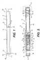
- FIG. 1is a side view of an e-vaping device according to at least one example embodiment.
- an electronic vaping device (e-vaping device) 60may include a replaceable cartridge (or first section) 70 and a reusable battery section (or second section) 72, which may be coupled together at a threaded connector 205.
- the connector 205may be any type of connector, such as at least one of a snug-fit, detent, clamp, bayonet, or clasp.
- the connector 205may be the connector described in U.S. Application Serial No. 15/154,439, filed May 13, 2016 . As described in U.S. Application Serial No. 15/154,439 , the connector 205 may be formed by a deep drawn process.
- the first section 70may include a housing 6 and the second section 72 may include a second housing 6'.
- the e-vaping device 60includes a mouth-end insert 8.
- the housing 6 and the second housing 6'may have a generally cylindrical cross-section. In other example embodiments, the housings 6 and 6' may have a generally triangular cross-section along one or more of the first section 70 and the second section 72. Furthermore, the housings 6 and 6' may have the same or different cross-section shape, or the same or different size. As discussed herein, the housings 6 and 6' may also be referred to as outer or main housings.
- the e-vaping device 60may include a conductive contact assembly 300 including a first contact 310 (shown in FIGS. 2-3 and 5-6 ), a second contact 320, and an end cap housing 340, which are described in more detail below.
- a conductive contact assembly 300including a first contact 310 (shown in FIGS. 2-3 and 5-6 ), a second contact 320, and an end cap housing 340, which are described in more detail below.
- Each of the first contact 310 and the second contact 320may be used in charging the power supply of the e-vaping device.
- the first contact 310, the second contact 320, and the end cap housing 340are described in more detail below.
- the first contact 310, the second contact 320, or bothmay be utilized in charging the power supply of the e-vaping device as well as for inputting touch commands.
- the conductive contact assembly 300may be configured to be used to charge the power supply of the e-vaping device and to input touch commands to control the e-vaping device.
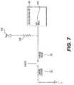
- FIG. 2is a cross-sectional view along line II-II of the e-vaping device of FIG. 1 .
- the first section 70may include a reservoir 22 configured to store a pre-vapor formulation and a heater 14 that may vaporize the pre-vapor formulation, which may be drawn from the reservoir 22 by a wick 28.
- the e-vaping device 60may include the features set forth in U.S. Patent Application Publication No. 2013/0192623 to Tucker et al. filed January 31, 2013 .
- the e-vaping devicemay include the features set forth in at least one of U.S. Patent Application Serial No. 15/135,930 filed April 22, 2016 , U.S. Patent Application Serial No. 135,923 filed April 22, 2016 , and U.S. Patent No. 9,289,014 issued March 22, 2016 .
- the pre-vapor formulationis a material or combination of materials that may be transformed into a vapor.
- the pre-vapor formulationmay be at least one of a liquid, solid or gel formulation including, but not limited to, water, beads, solvents, active ingredients, ethanol, plant extracts, natural or artificial flavors, vapor formers such as glycerin and propylene glycol, and combinations thereof.
- the first section 70may include the housing 6 extending in a longitudinal direction and an inner tube (or chimney) 62 coaxially positioned within the housing 6.
- a nose portion 61 of a gasket (or seal) 15may be fitted into the inner tube 62, and an outer perimeter of the gasket 15 may provide a seal with an interior surface of the housing 6.
- the gasket 15may also include a central, longitudinal air passage 20 in fluid communication with the inner tube 62 to define an inner passage (also referred to as a central channel or central inner passage) 21.
- a transverse channel 33 at a backside portion of the gasket 15may intersect and communicate with the air passage 20 of the gasket 15. This transverse channel 33 assures communication between the air passage 20 and a space 35 defined between the gasket 15 and a first connector piece 37.
- the first connector piece 37may include a male threaded section for effecting the connection between the first section 70 and the second section 72.
- more than two air inlet ports 44may be included in the housing 6.
- a single air inlet port 44may be included in the housing 6.
- Such arrangementallows for placement of the air inlet ports 44 close to the connector 205 without occlusion by the presence of the first connector piece 37. This arrangement may also reinforce the area of air inlet ports 44 to facilitate precise drilling of the air inlet ports 44.
- the air inlet ports 44may be provided in the connector 205 instead of in the housing 6.
- the connector 205may not include threaded portions.
- the at least one air inlet port 44may be formed in the housing 6, adjacent the connector 205 to minimize the chance of an adult vaper's fingers occluding one of the ports and to control the resistance-to-draw (RTD) during vaping.
- the air inlet ports 44may be machined into the housing 6 with precision tooling such that their diameters are closely controlled and replicated from one e-vaping device 60 to the next during manufacture.
- the air inlet ports 44may be sized and configured such that the e-vaping device 60 has a resistance-to-draw (RTD) in the range of from about 60 millimetres of water to about 150 millimetres of water.
- RTDresistance-to-draw
- a nose portion 93 of a second gasket 10may be fitted into a first end portion 81 of the inner tube 62.
- An outer perimeter of the second gasket 10may provide a substantially tight seal with an interior surface 97 of the housing 6.
- the second gasket 10may include a central channel 63 disposed between the inner passage 21 of the inner tube 62 and the interior of the mouth-end insert 8, which may transport the vapor from the inner passage 21 to the mouth-end insert 8.
- the mouth-end insert 8includes at least two outlets, which may be located off-axis from the longitudinal axis of the e-vaping device 60. The outlets may be angled outwardly in relation to the longitudinal axis of the e-vaping device 60.
- the outletsmay be substantially uniformly distributed about the perimeter of the mouth-end insert 8 so as to substantially uniformly distribute vapor in an adult vaper's mouth during vaping and create a greater perception of fullness in the mouth. Therefore, as the vapor passes into the adult vaper's mouth, the vapor may enter the mouth and may move in different directions so as to provide a full mouth feel.
- the space defined between the gaskets 10 and 15 and the housing 6 and the inner tube 62may establish the confines of a reservoir 22.
- the reservoir 22may contain a pre-vapor formulation, and optionally a storage medium (not shown) configured to store the pre-vapor formulation therein.
- the storage mediummay include a winding of cotton gauze or other fibrous material about the inner tube 62.
- the reservoir 22may be contained in an outer annulus between the inner tube 62 and the housing 6 and between the gaskets 10 and 15. Therefore, the reservoir 22 may at least partially surround the inner passage 21.
- the heater 14may extend transversely across the inner passage 21 between opposing portions of the reservoir 22. In some example embodiments, the heater 14 may extend parallel to a longitudinal axis of the inner passage 21.
- the reservoir 22may be sized and configured to hold enough pre-vapor formulation such that the e-vaping device 60 may be configured for vaping for at least about 200 seconds. Moreover, the e-vaping device 60 may be configured to allow each puff to last a maximum of about 5 seconds.
- the storage mediummay be a fibrous material including at least one of cotton, polyethylene, polyester, rayon and combinations thereof.
- the fibersmay have a diameter ranging in size from about 6 microns to about 15 microns (for example, about 8 microns to about 12 microns or about 9 microns to about 11 microns).
- the storage mediummay be a sintered, porous or foamed material.
- the fibersmay be sized to be irrespirable and may have a cross-section which has a Y-shape, cross shape, clover shape or any other suitable shape.
- the reservoir 22may include a filled tank lacking any storage medium and containing only pre-vapor formulation.
- pre-vapor formulationmay be transferred from the reservoir 22, storage medium, or both, to the proximity of the heater 14 via capillary action of the wick 28.
- the wick 28may include at least a first end portion and a second end portion, which may extend into opposite sides of the reservoir 22.
- the heater 14may at least partially surround a central portion of the wick 28 such that when the heater 14 is activated, the pre-vapor formulation in the central portion of the wick 28 may be vaporized by the heater 14 to form a vapor.
- the wick 28may include filaments (or threads) having a capacity to draw the pre-vapor formulation.
- the wick 28may be a bundle of glass (or ceramic) filaments, a bundle including a group of windings of glass filaments, and so forth, all of which arrangements may be capable of drawing pre-vapor formulation via capillary action by interstitial spacings between the filaments.
- the filamentsmay be generally aligned in a direction perpendicular (transverse) to the longitudinal direction of the e-vaping device 60.
- the wick 28may include one to eight filament strands, each strand comprising a plurality of glass filaments twisted together. The end portions of the wick 28 may be flexible and foldable into the confines of the reservoir 22.
- the filamentsmay have a cross-section that is generally cross-shaped, clover-shaped, Y-shaped, or in any other suitable shape.
- the wick 28may include any suitable material or combination of materials. Examples of suitable materials may be, but not limited to, glass, ceramic- or graphite-based materials.
- the wick 28may have any suitable capillarity drawing action to accommodate pre-vapor formulations having different physical properties such as density, viscosity, surface tension and vapor pressure.
- the wick 28may be non-conductive.
- the heater 14may include a wire coil which at least partially surrounds the wick 28.
- the wiremay be a metal wire.
- the heater coilmay extend fully or partially along the length of the wick 28.
- the heater coilmay further extend fully or partially around the circumference of the wick 28.
- the heater 14may or may not be in contact with the wick 28.
- the heater coilmay be formed of any suitable electrically resistive materials.
- suitable electrically resistive materialsmay include, but not limited to, copper, titanium, zirconium, tantalum and metals from the platinum group.
- suitable metal alloysinclude, but not limited to, stainless steel, nickel, cobalt, chromium, aluminum-titanium-zirconium, hafnium, niobium, molybdenum, tantalum, tungsten, tin, gallium, manganese and iron-containing alloys, and super-alloys based on nickel, iron, cobalt, stainless steel.
- the heater 14may be formed of nickel aluminide, a material with a layer of alumina on the surface, iron aluminide and other composite materials, the electrically resistive material may optionally be embedded in, encapsulated or coated with an insulating material or vice-versa, depending on the kinetics of energy transfer and the external physicochemical properties required.
- the heater 14may include at least one material selected from the group consisting of stainless steel, copper, copper alloys, nickel-chromium alloys, super alloys and combinations thereof.
- the heater 14may be formed of nickel-chromium alloys or iron-chromium alloys.
- the heater 14may be a ceramic heater having an electrically resistive layer on an outside surface thereof.
- the inner tube 62may include a pair of opposing slots, such that the wick 28 and the first and second electrical leads 109 and 109' or ends of the heater 14 may extend out from the respective opposing slots.
- the provision of the opposing slots in the inner tube 62may facilitate placement of the heater 14 and wick 28 into position within the inner tube 62 without impacting edges of the slots and the coiled section of the heater 14. Accordingly, edges of the slots may not be allowed to impact and alter the coil spacing of the heater 14, which would otherwise create potential sources of hotspots.
- the inner tube 62may have a diameter of about 4 millimetres and each of the opposing slots may have major and minor dimensions of about 2 millimetres by about 4 millimetres.
- the first lead 109is physically and electrically connected to the male threaded connector piece 37.
- the male threaded first connector piece 37is a hollow cylinder with male threads on a portion of the outer later surface.
- the connector pieceis conductive, and may be formed or coated with a conductive material.
- the second lead 109'is physically and electrically connected to a first conductive post 110.
- the first conductive post 110may be formed of a conductive material (for example, stainless steel, copper, and so forth), and may have a T-shaped cross-section as shown in FIG. 2 .
- the first conductive post 110nests within the hollow portion of the first connector piece 37, and is electrically insulated from the first connector piece 37 by an insulating shell 111.
- the first conductive post 110may be hollow as shown, and the hollow portion may be in fluid communication with the air passage 20. Accordingly, the first connector piece 37 and the first conductive post 110 form respective external electrical connection to the heater 14.
- the heater 14may heat pre-vapor formulation in the wick 28 by thermal conduction.
- heat from the heater 14may be conducted to the pre-vapor formulation by means of a heat conductive element or the heater 14 may transfer heat to the incoming ambient air that is drawn through the e-vaping device 60 during vaping, which in turn heats the pre-vapor formulation by convection.
- the heater 14may include a porous material which incorporates a resistance heater formed of a material having a high electrical resistance capable of generating heat quickly.
- the second section 72includes a power supply 1, a control circuit 200, sensor 16, and conductive contact assembly (also referred to as a contact assembly or connector assembly) 300.
- the control circuit 200 and sensor 16are disposed in the housing 6'.
- the contact assembly 300forms one end of the second section 72, and a female threaded second connector piece 112 forms a second end.
- the second connector piece 112has a hollow cylinder shape with threading on an inner later surface.
- the inner diameter of the second connector piece 112matches that of the outer diameter of the first connector pieces 37 such that the two connector pieces 37 and 112 may be threaded together to form a connection 205.
- the second connector piece 112, or at least the other later surfaceis conductive, for example, formed of or including a conductive material. As such, an electrical and physical connection occurs between the first and second connector pieces 37 and 112 when connected.
- a first lead 720electrically connects the second connector piece 112 to the control circuit 200.
- a second lead 730electrically connects the control circuit 200 to a first terminal 113 of the power supply 1.
- a third lead 725electrically connects a second terminal 114 of the power supply 1 to the power terminal of the control circuit 200 to provide power to the control circuit 200.
- the second terminal 114 of the power supply 1is also physically and electrically connected to a second conductive post 115.
- the second conductive post 115may be formed of a conductive material (for example, stainless steel, copper, and so forth), and may have a T-shaped cross-section as shown in FIG. 2 .
- the second conductive post 115nests within the hollow portion of the second connector piece 112, and is electrically insulated from the second connector piece 112 by an insulating shell 116.
- the second conductive post 115may also be hollow as shown. When the first and second connector pieces 37 and 112 are mated, the second conductive post 115 physically and electrically connects to the first conductive post 110. Also, the hollow portion of the second conductive post 115 may be in fluid communication with the hollow portion of the first conductive post 110.
- first section 70has been shown and described as having the male connector piece and the second section 72 has been shown and described as having the female connector piece, an alternative embodiment includes the opposite where the first section 70 has the female connector piece and the second section 72 has the male connector piece.
- the power supply 1includes a battery arranged in the e-vaping device 60.
- the power supply 1may be a Lithium-ion battery or one of its variants, for example a Lithium-ion polymer battery.
- the power supply 1may be a nickel-metal hydride battery, a nickel cadmium battery, a lithium-manganese battery, a lithium-cobalt battery or a fuel cell.
- the e-vaping device 60may be vapable by an adult vaper until the energy in the power supply 1 is depleted or in the case of lithium polymer battery, a minimum voltage cut-off level is achieved.
- the power supply 1is rechargeable.
- the second section 72may include circuitry configured to allow the battery to be chargeable by an external charging device.
- an USB charger or other suitable charger assemblymay be used as described below.
- the sensor 16is configured to generate an output indicative of a magnitude and direction of airflow in the e-vaping device 60.
- the control circuit 200receives the output of the sensor 16, and determines if (1) the direction of the airflow indicates a draw on the mouth-end insert 8 (versus blowing) and (2) the magnitude of the draw exceeds a threshold level. If these vaping conditions are met, the control circuit 200 electrically connects the power supply 1 to the heater 14; therefore, activating the heater 14. Namely, the control circuit 200 electrically connects the first and second leads 720 and 730 (for example, by activating a heater power control circuit 945 as discussed below with regard to FIG. 6 ) such that the heater 14 becomes electrically connected to the battery 1.
- the sensor 16may indicate a pressure drop, and the control circuit 200 activates the heater 14 in response thereto.
- the control circuit 200may also include a light 48, which the control circuit 200 activates to glow when the heater 14 is activated, when the battery is recharged, or both.
- the light 48may include one or more light-emitting diodes (LEDs).
- the LEDsmay include one or more colors (for example, white, yellow, red, green, blue, and so forth).
- the light 48may be arranged to be visible to an adult vaper during vaping, and may be positioned between a first end 210 and a second end 220 of the e-vaping device 60.
- the light 48may be utilized for e-vaping system diagnostics or to indicate that recharging is in progress.
- the light 48may also be configured such that the adult vaper may activate, deactivate, or activate and deactivate the heater activation light 48 for privacy.
- control circuit 200may include a time-period limiter.
- control circuit 200may include a manually operable switch for an adult vaper to initiate heating.
- the time-period of the electric current supply to the heater 14may be set or pre-set depending on the amount of pre-vapor formulation desired to be vaporized.
- the sensor 16may detect a pressure drop and the control circuit 200 may supply power to the heater 14 as long as heater activation conditions are met.
- airis drawn primarily into the first section 70 through the at least one air inlet 44 in response to a draw on the mouth-end insert 8.
- the airpasses through the air inlet 50, into the transverse channel 33 at the backside portion of the gasket 15 and into the air passage 20 of the gasket 15, into the inner passage 21, and through the outlet 24 of the mouth-end insert 8.
- the control circuit 200detects the vaping conditions discussed above, the control circuit 200 initiates power supply to the heater 14, such that the heater 14 heats pre-vapor formulation in the wick 28 to form a vapor.
- the vapor and air flowing through the inner passage 21combine and exit the e-vaping device 60 via the outlet 24 of the mouth-end insert 8.
- the heater 14When activated, the heater 14 may heat a portion of the wick 28 surrounded by the heater for less than about 10 seconds.
- the first section 70may be replaceable. In other words, once the pre-vapor formulation of the cartridge is depleted, only the first section 70 may be replaced.
- An alternate arrangementmay include an example embodiment where the entire e-vaping device 60 may be disposed once the reservoir 22 is depleted.
- the e-vaping device 60may be a one-piece e-vaping device.
- the e-vaping device 60may be about 80 millimetres to about 110 millimetres long and about 7 millimetres to about 8 millimetres in diameter.
- the e-vaping devicemay be about 84 millimetres long and may have a diameter of about 7.8 millimetres.
- the e-vaping device 60includes the contact assembly 300 as described in greater detail below with reference to FIGS. 4-5 .
- FIG. 3Ais an enlarged view of an end of the second (or battery) section of an e-vaping device according to at least one example embodiment.
- the second section 72is the same as in FIG. 2 .
- the control circuit 200is disposed on a rigid printed circuit board 410.
- the circuit board 410is connected to the first contact 310 via lead 700.
- the circuit board 410is connected to the second contact 320 via lead 710.
- FIG. 3Bis an enlarged view of an end of the second section of an e-vaping device according to at least one example embodiment.
- the second section 72is the same as in FIG. 2 .
- the control circuit 200is disposed on a flexible printed circuit board 1000.
- the flexible printed circuit board 1000allows for the inclusion of a larger battery 1 since the flexible printed circuit board 1000 requires less space within the housing 6' than the rigid circuit board 410 of FIG. 3A .
- FIG. 4is an exploded view of the conductive contact assembly of FIG. 2 according to at least one example embodiment.
- FIG. 5is a cross-sectional view of an assembled (or non-exploded) version of the conductive contact assembly of FIG. 4 along line V-V of FIG. 4 according to at least one example embodiment.
- the contact assembly 300is the same as shown in FIG. 2 , and is shown in greater detail. As shown in FIG. 4 , the contact assembly 300 includes the first contact 310, the second contact 320, and the end cap housing 340.
- the first contact 310has a disk shape.
- the first contact 310may be formed of a printed circuit board (PCB), which may be rigid or flexible.
- the first contact 310includes a substrate 315 with a first conductive portion 312 formed on an upper surface thereof and a second conductive portion 314 formed on a bottom surface thereof. At least one conductive via 313 electrically connects the first and second conductive portions 312 and 314 (see FIG. 5 ).
- the first conductive portion 312 and the second conductive portion 314may be copper, stainless steel, magnetic stainless steel, and so forth.
- the first conductive portion 312may have a generally circular shape, may form a pattern, or both.
- the conductive portion 312forms the outline of the number "10" in the example of FIG. 4 .
- the first conductive portion 312has an area such that the second contact 320 does not overlap the first conductive portion 312, and the first conductive portion 312 of the first contact 310 is electrically insulated from the second contact 320. Instead, a non-conductive portion 311 of the substrate 315 is exposed, and the second contact 320 overlaps, contacts, or overlaps and contacts the non-conductive portion 311.
- the end cap housing 340has a generally, hollow cylindrical shape defined by a sidewall 350.
- a lower portion of the sidewall 350includes ridges 355, and an upper portion includes a flange 360.
- the flange 360has an outer diameter that is about the same as the outer diameter of the housing 6'.
- the sidewall 350has an outer diameter that is slightly less than an inner diameter of the housing 6' so that the sidewall 350 may be held in place in the housing 6' by friction fit.
- the sidewall 350may include the ridges 355 to aid in holding the end cap housing 340 within the housing 6'.
- the end cap housing 340includes a ridge or inner ledge 305 projecting from the inner later surface.
- the first contact 310rests on the inner ledge 305.
- Two projecting fins 315project from an end of the end cap housing 340.
- the projecting fins 315separate the inner ledge 305 from the flange 360.
- the second contact 320rests on an outer ledge of the flange 360. While two projecting fins 315, each extending at least 90 degrees around the end of the end cap housing 340 are shown, it will be understood the more or less than two projecting fins 315 may be formed.
- a portion of the second contact 320mates with the flange 360 of the end cap housing 340, and in doing so, tabs 380 of the second contact 320 fit in slots 390 in the sidewall 350 of the end cap housing 340 so as to secure the second contact 320 with the end cap housing 340, and hold the first contact 310 in place against the inner ledge 305.
- the lead 700is connected to the second conductive portion 314 and the lead 710 is connected to at least one of the tabs 380.
- the end cap housing 340may be formed of plastic. At least a portion of the flange 360 of the end cap housing 340 may be transparent so that light from the heater activation light 48 may be seen through the flange 360.
- the first contact 310 and the second contact 320may be opaque (for example, may include a solder mask to substantially prevent light from being seen through the PCB), such that the light 48 may not be seen through the end of the e-vaping device 60.
- stops 440are disposed on the tabs 380, and the stops latch beneath a portion 450 of the flange 360 when the tabs 380 are mated with the slots 390.
- the tabs 380may be resilient such that the tabs 380 bend slightly when being inserted into the slots 390, but spring back into an original position to lock the tabs 380 within the slots 390.
- the second contact 320is conductive, and conductive portions of the first contact 310 are electrically isolated from the second contact 320 as described above. Also, in at least one example embodiment, the first contact 310 and the second contact 320 are magnetic. Accordingly, the tabs 380 and the slots 390 are configured to lock together so as to prevent magnetic attraction from removing the first contact 310 and the second contact 320 from the e-vaping device 60.
- At least a portion of the first contact 310may be substantially transparent such that the light 48 shines through a side portion of the end cap housing 340.
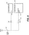
- FIG. 6is a circuit diagram illustrating an example embodiment of the control circuit 200 of the e-vaping device shown in FIG. 1 .
- the control circuit 200 shown in FIG. 6is described with regard to a situation in which the first section 70 is connected to the second section 72 as discussed above. Therefore, both the heater 14 and the power supply 1 are shown in FIG. 6 .
- the control circuit 200includes a microcontroller 905, a charge controller 800, a mode control switch circuit 920, a heater power control circuit 945, a resistance measurement circuit 94 and a resistor 910.
- the mode control switch circuit 920includes a mode control switch U3
- the heater power control circuit 945includes a heater power control switch U1.
- the microcontroller 905includes an analog-to-digital converter (ADC) 9052 and a digital-to-analog converter (DAC) 9054.
- ADC 9052may be a 10-bit ADC and the DAC 9054 may be an 8-bit DAC.
- example embodimentsshould not be limited to these examples.
- the resistance measurement circuit 94includes a first resistor R1, a second resistor R2, a third resistor R3, a fourth resistor R4, an operational amplifier (OP-AMP) 947 and a resistance measurement switch circuit 946.
- the resistance measurement switch circuit 946includes a resistance measurement switch U2.
- the OP-AMP 947may be a differential operational amplifier.
- Each of the heater power control switch U1, the resistance measurement switch U2 and the mode control switch U3may be transistors (for example, NMOS or MOSFET transistors), although example embodiments should not be limited to these examples.
- the switches U1 through U3will be described herein as transistors.
- the heater power control switch U1may be referred to as a heater power control transistor U1
- the resistance measurement switch U2may be referred to as a resistance measurement transistor U2
- the mode control switch U3may be referred to as mode control transistor U3.
- example embodimentsshould not be limited to these examples.
- a capacitive input 940 of the microcontroller 905is connected to a first terminal of the resistor 910.
- a second terminal of the resistor 910is connected to the second contact 320 via the lead 710.
- a first terminal of the mode control transistor U3is connected to a first node NODE1 between the second terminal of the resistor 910 and the second contact 320.
- a second terminal of the mode control switch U3is connected to the negative terminal of the power supply 1, a first end of the heater 14 and a first terminal of the fifth resistor R4 of the resistance measurement circuit 94 at second node NODE2.
- a gate of the mode control transistor U3is connected to a touch/charge enable terminal 930 (also referred to herein as an enable terminal) at the microcontroller 905.
- the negative terminal of the power supply 1may also be referred to as common ground, ground, ground plane or common ground plane.
- the charge controller 800is electrically connected between the first contact 310 (via the lead 700) and the charge enable terminal 935 of the microcontroller 905.
- the charge controller 800is also electrically connected to the positive terminal of the power supply 1 at a third node NODE3.
- the positive terminal of the power supply 1is connected to the control circuit 200 via lead 703, and also connected to the power input terminal PWR of the microcontroller 905 via the lead 725 to provide power to the control circuit 200 and the microcontroller 905.
- the charge controller 800may be any known charge controller.
- the charge controller 800may include a linear regulator.
- the charge controller 800may be configured to determine a level of charge of the power supply 1, and to control application of charging current i CH , voltage, or both, to the power supply 1 based on the determined level of charge.
- the charge controller 800may also detect input of a charging current i CH via the first contact 310 and the lead 700, and output a charge enable signal CHG_EN based on the detected charging current i CH .
- the charge enable signal CHG_ENmay be disabled (for example, have a first logic value, such as a logic low) when no charging current is detected, and may be enabled (for example, have a second logic value, such as a logic high level) when the charging current is detected.
- the charge enable signal CHG_ENmay be described as being output when the charging current is detected, and not output when no charging current is detected.
- the charge controller 800may also output regulated charging current i CH to the positive terminal of the power supply 1 to charge the power supply 1. Because charge controllers such as this are well-known, a more detailed discussion is omitted.
- a first terminal of the heater power control transistor U1is connected to the positive terminal of the power supply 1 and a second terminal of the heater power control transistor U1 is connected to a second end of the heater 14 at a fourth node NODE4 via the first lead 720 between the heater 14 and the control circuit 200.
- a gate of the heater power control transistor U1is electrically connected to a heater power control terminal 955 of the microcontroller 905.
- the microcontroller 905outputs a heater power control signal HEAT_PWR_CTRL to control the heater power control transistor U1 to regulate and control power from the power supply 1 to the heater 14.
- the resistance measurement circuit 94is electrically connected to the first terminal of the heater power control transistor U1, the positive terminal of the power supply 1 and the charge controller 800 at a fifth node NODE5, via node NODE3.
- the resistance measurement circuit 94is also electrically connected to the ADC 9052, the DAC 9054 and a resistance measurement enable terminal 956 at the microcontroller 905.
- a first terminal of the resistance measurement transistor 946is connected to the first terminal of the heater power control transistor U1, the positive terminal of the power supply 1 and the charge controller 800 at the fifth node NODE5.
- a second terminal of the resistance measurement transistor 946is connected to a first terminal of first resistor R1.
- the gate of the resistance measurement transistor 946is connected to the resistance measurement enable terminal 956 at the microcontroller 905.
- the second terminal of the first resistor R1is connected to a positive input of the operational amplifier (OP-AMP) 947, the second terminal of the heater power control transistor U1, the second end of the heater 14 and an analog input ANALOG of the microcontroller 905 at a sixth node NODE6.
- OP-AMPoperational amplifier
- the output terminal of the OP-AMP 947is connected to the ADC 9052 at the microcontroller 905.
- the second resistor R2is connected in parallel between the negative input terminal and the output terminal of the OP-AMP 947.
- the negative input terminal of the OP-AMP 947is also connected to a first terminal of the third resistor R3 and a second terminal of the fourth resistor R4.
- the second terminal of the third resistor R3is connected to the DAC 9054 at the microcontroller 905.
- the microcontroller 905is also electrically connected to the sensor 16.
- the resistance measurement circuit 94may be included and implemented in the microcontroller 905.
- the mode control transistor U3when the first section 70 is connected to the second section 72, the mode control transistor U3 is initially set to the ON state.
- the mode control transistor U3transitions from the ON state to the OFF state periodically based on a monitoring frequency for the control circuit 200 in response to switching of a charge monitoring signal EN_SIG from the microcontroller 905 via the enable terminal 930 (also referred to herein as an enable terminal).
- the monitoring frequencyis discussed in more detail later.
- This relatively short intervalmay occur at the beginning of what may be referred to as a "wake" cycle based on the sleep state of the microcontroller, after which the control circuit 200 may return to a state in which charging of power supply 1 may be initiated.
- switching of the charge monitoring signal EN_SIGmay refer to transitioning of the signal from the logic high to the logic low level.
- switching of the charge monitoring signal EN_SIG to the logic low levelmay also be referred to as disabling or disabling output of the charge monitoring signal EN_SIG.
- example embodimentsshould not be limited to this example.
- the ON state of the mode control transistor 920may also be referred to as an active state, or as the mode control transistor 920 being activated.
- the OFF statemay also be referred to as an inactive state or as the mode control transistor 920 being deactivated.
- the microcontroller 905, the control circuit 200, or bothmay operate in one of a monitoring mode, a touch command mode and a charging mode. Example operation of the control circuit 200 in each of these operating modes will be discussed in more detail below.
- the charging enable signal CHG_ENis disabled, and the mode control transistor U3 is periodically deactivated in response to disabling of the charge monitoring signal EN_SIG from the enable terminal 930 of the microcontroller 905.
- Disabling of the charge monitoring signal EN_SIGmay also be characterized as enabling a touch monitoring signal.
- the frequency of the charge monitoring signal EN_SIG, and consequently the periodicity of the deactivation of the mode control transistor U3,is based on a state of the microcontroller 905 in the monitoring mode.
- the monitoring modemay include a plurality of states. In each of the plurality of states, the charge monitoring signal EN_SIG may have a different frequency, and therefore, the deactivation of the mode control transistor U3 may have a different periodicity.
- the monitoring modemay include an active state, a standby state and a hibernate state.
- the charge monitoring signal EN_SIGmay have a frequency of about 100 hertz, such that the mode control transistor U3 is deactivated (transitions to the OFF state) about every 0.01 seconds.
- the charge monitoring signal EN_SIGmay have a frequency of about 50 hertz, such that the mode control transistor U3 is deactivated about every 0.05 seconds.
- the charge monitoring signal EN_SIGmay have a frequency of about 10 hertz such that the mode control transistor U3 is deactivated about every 0.10 seconds.
- the microcontroller 905detects that the cartridge is attached to the battery section and defaults to the active state. As is generally well-known, the microcontroller 905 may detect attachment of a cartridge to the battery section based on a change in resistance (for example, from essentially infinite resistance to a finite resistance value) resulting from attachment of the cartridge.
- the microcontroller 905transitions to the standby state. While in the standby state, if no puff event is detected by the sensor 16 within a second threshold time period (for example, 40 seconds) from attachment of the cartridge (or, alternatively, another interval of 20 seconds from the time at which the microcontroller 905 transitioned to the standby state), then the microcontroller 905 transitions to the hibernate state. The microcontroller stays in the hibernate state until a puff event is detected by the sensor 16.
- a first threshold intervalfor example, about 20 seconds
- the microcontroller 905transitions to the active state to increase responsiveness to an adult vaper. When no cartridge is attached, the microcontroller 905 remains in the hibernate state until a cartridge is attached. As discussed above, when the cartridge is attached, the microcontroller 905 transitions to the active state.
- FIG. 14is a flow chart illustrating an example of a method of operating the control circuit 200 shown in FIG. 6 .
- the example shown in FIG. 14will be discussed with regard to the microcontroller 905 initially operating in the monitoring mode with the mode control transistor 920 in the ON state. However, examples should not be limited to this example.
- the mode control transistor U3is periodically deactivated by disabling the charge monitoring signal EN_SIG output from the enable terminal 930 of the microcontroller 905.
- the method shown in FIG. 14may be performed periodically when the mode control transistor 920 is deactivated. In this regard, the method shown in FIG. 14 may be performed according to the frequency of the charge monitoring signal EN_SIG.
- the microcontroller 905detects whether a touch has been input by an adult vaper.
- step S1404in one example, when the mode control transistor U3 is in the OFF state, and the adult vaper touches the second contact 320, the part of the adult vaper (for example, the finger) touching the second contact 320 and the second contact 320 itself act as terminals of a capacitor, which changes the measured capacitance along the circuit path between the second contact 320 and the capacitive input 940.
- the microcontroller 905detects this change in capacitance, the microcontroller 905 determines that the adult vaper has touched the second contact 320, thereby detecting a touch input by the adult vaper.
- microcontroller 905does not detect a touch input by an adult vaper at step S1404, then the microcontroller 905 remains in the monitoring mode and operates as discussed above.
- step S1404if the microcontroller 905 detects a touch input, then the microcontroller 905 enters the touch command mode at step S1406.
- the mode control transistor 920is maintained in the OFF state to electrically isolate the contact 320, lead 710 and resistor 910 from at least the heater 14 and the negative terminal of the power supply 1. Since the default state of the mode control transistor U3 is ON, the microcontroller 905 maintains the mode control transistor U3 in the OFF state by preventing the charge monitoring signal EN_SIG from being enabled (or from being output) and turning on the mode control transistor 920.
- the microcontroller 905detects a touch command input by the adult vaper at step S1408. According to at least some example embodiments, the microcontroller 905 detects the touch command input by the adult vaper based on the frequency, length, or frequency and length of the touch by the adult vaper.
- the microcontroller 905executes the detected touch command at step S1410.
- the e-vaping devicemay respond to a variety of different touch commands.
- the vaping profilemay be altered by inputs or the device may be locked from vaping by tapping the contact assembly.
- the microcontroller 905may return to the monitoring mode.
- FIG. 15is a flow chart illustrating another example of a method of operating the control circuit 200 shown in FIG. 6 .
- the example shown in FIG. 15will also be discussed with regard to the microcontroller 905 initially operating in the monitoring mode with the mode control transistor U3 in the ON state. However, examples should not be limited to this example.
- the microcontroller 905determines whether the power supply 1 is being charged based on the charging enable signal CHG_EN from the charge controller 800. As mentioned above, the charge controller 800 outputs the charging enable signal CHG_EN based on the presence of the charging current i CH through the first contact 310 and the lead 700. In one example, the microcontroller 905 determines that the power supply 1 is being charged if the charge enable signal CHG_EN from the charge controller 800 is enabled (for example, has logic high level). As discussed herein, the enabling of the charge enable signal CHG_EN may also be referred to as output of the charge enable signal CHG_EN.
- microcontroller 905If the microcontroller 905 detects that the power supply 1 is charging at step S1504, then the microcontroller 905 enters the charging mode at step S1508.
- the mode control transistor 920In the charging mode, the mode control transistor 920 remains in the ON state until the charge controller 800 indicates that the charging current i CH is no longer flowing to the positive terminal of the power supply 1 by disabling the charge enable signal CHG_EN. In one example, while in the charging mode, the microcontroller 905 maintains the mode control transistor 920 in the ON state by preventing disabling of the enabled charge monitoring signal EN_SIG.
- the microcontroller 905may return to the monitoring mode.
- step S1504if the microcontroller 905 does not detect that the power supply 1 is charging, then the microcontroller 905 remains in the monitoring mode and operates as discussed above.
- control circuit 200further includes a resistance measurement circuit 94.
- the application of power to the heater 14changes the resistance coefficient of the heater 14, which results in an increase in the resistance of the heater 14.
- the microcontroller 905is configured to monitor resistance changes in the heater 14 during puff events, and to control power to the heater 14 based on the changes in resistance.
- the microcontroller 905may selectively disable vaping operation by cutting power to the heater 14 based on changes in resistance of the heater 14.
- the first resistor R1is a precise reference resistor with known resistance value (for example, about 10.00 ohms).
- the resistors R2, R3 and R4are stable resistors used to set the gain and bias of the OP-AMP 947.
- the resistors R2, R3, and R4also have known resistance values.
- the DAC 9054 and the ADC 9052share the same reference voltage V battery .
- the reference voltage V batteryis the voltage of the power supply 1.
- the voltage output V op-amp of the OP-AMP 947is given by Equation (1) shown below.
- V op ⁇ ampR 2 + R 3 R 4 R 3 + R 4 R 3 R 4 R 3 + R 4 ⁇ R coil R coil + R 1 ⁇ V battery ⁇ R 2 R 3 ⁇ CODE DAC 2 8 ⁇ V battery
- the resistance measurement circuit 94may operate in a calibration mode or phase and a monitoring mode or phase.
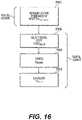
- FIG. 16is a flow chart illustrating an example of a method of operating the control circuit 200 in the calibration phase.
- the microcontroller 905defaults to the active state.
- the control circuit 200enters the calibration phase.
- the calibration phaseis also referred to as the fine resistance calibration phase.
- the stress on the heater 14 during a puff eventmay cause a shift in the "at-rest” resistance of the heater coil.
- the "at-rest" resistancemay change as much as 0.5 percent from a previous value.
- the microcontroller 905may monitor the length of time between puff events, and if the time interval between puff events exceeds a threshold value (for example, about 25 seconds), the control circuit 200 may also enter the calibration phase. Accordingly, the control circuit 200 may enter the calibration phase in response to at least two trigger events; that is, attachment of a new cartridge to the second section 72, and if the time interval between puff events exceeds a threshold value.
- the microcontroller 905measures the coarse resistance of the heater coil R coil _ coarse .
- the coarse resistance of the heater coilis a low resolution measurement by the microcontroller 905 in the analog domain.
- the arrangement of heater 14 and the first resistor R1, which is a known stable resistance, in the resistance measurement circuit 94presents a voltage at the sixth node NODE6, which is input to, sensed at, or input to and sensed at the analog input ANALOG of the microcontroller 905.
- the first resistor R1 and the coil of the heater 15create a voltage divider circuit.
- the microcontroller 905calculates the resistance of heater 14 based on the known voltage of the power supply (for example, V in ), the sensed or measured voltage at the sixth node NODE6 (for example, V out ) and the known resistance of the first resistor R1.
- the OP-AMP 947may be a component integrated in microcontroller 905.
- the coarse resistance measurement R coil_coarseis acquired by reconfiguring the positive input of OP-AMP 947 as an ADC input of microcontroller 905.
- the arrangement of heater 14 and the first resistor R1which is a known stable resistance, presents a voltage on NODE6 based on which the microcontroller 905 may calculate the resistance of heater 14.
- the microcontroller 905may calculate the resistance of the heater 14 in the same manner as discussed above.
- the microcontroller 905selects an appropriate digital code or word CODE DAC based on the initial coarse resistance measurement R coil _ coarse . According to at least one example embodiment, the microcontroller 905 selects the digital code CODE DAC so that the output voltage V op-amp of the OP-AMP 947 does not saturate the input of the ADC 9052 during subsequent measurements. In one example, the digital code CODE DAC may be selected such that the output of the OP-AMP 947 is substantially zero.
- the ADC 9052 at the microcontroller 905samples the voltage output V op-amp of the OP-AMP 947 to generate a digital representation CODE ADC _0 of the voltage output V op-amp of the OP-AMP 947.
- the microcontroller 905calculates the initial resistance of the heater coil R coil_ 0 based on the sampled voltage output V op-amp of the OP-AMP 947 thereby completing the calibration phase of the resistance measurement circuit 94.
- the digital code CODE DACis maintained to fix the voltage output of the DAC 9054.
- the heater power control signal HEAT_PWR_CTRLcontrols the heater power control transistor U1 to regulate the voltage output from the power supply 1 to the heater 14.
- the heater power control signal HEAT_PWR_CTRLhas a duty cycle of 64 milliseconds.
- the duty cycleincludes a regulating period and a resistance measurement period.
- the regulating periodmay be one of the first and the last 60 milliseconds of the 64 milliseconds, whereas the resistance measurement period may be the remaining portion of the duty cycle (for example, one of the first and last 4 milliseconds of the duty cycle).
- the heater power control signal HEAT_PWR_CTRLis pulse train causing the heater power control transistor U1 to switch on and off to regulate the voltage applied to the heater 14 by the power supply 1. Also during the regulating period of the duty cycle, the resistance measurement enable signal RES_MEAS_EN is disabled such that resistance measurement transistor U2 is maintained in the OFF (or open) state.
- the heater power control transistor U1is switched to the OFF (open) state, while the resistance measurement transistor U2 is maintained in the ON (closed) state for a given time interval sufficient to allow the microcontroller 905 to acquire a voltage sample from the output of the OP-AMP 947.
- the given time intervalmay be less than or equal to about 4 milliseconds (for example, about 1 milliseconds).
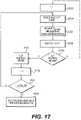
- FIG. 17is a flow chart illustrating an example of a method of operating the control circuit 200 in the resistance measurement phase. The method shown in FIG. 17 is performed during the resistance measurement period of the duty cycle during a puff event.
- the microcontroller 905in response to attaching a cartridge including a heater element (for example, first section 70) to the battery section (for example, second section 72), at step S1702 the microcontroller 905 initiates a counter value i for the cartridge to zero.
- the microcontroller 905utilizes the counter value i to track the number of (for example, consecutive) times power to the heater 14 is cutoff for the attached cartridge.
- the microcontroller 905After initializing the counter value i, when the sensor 16 detects a puff event at step S1704, the microcontroller 905 measures or samples the output voltage V op-amp from the OP-AMP 947 at step S1706. The microcontroller 905 then generates an updated digital representation ( CODE ADC _1 ) of the output voltage V op-amp of the OP-AMP 947 based on the sampled output voltage V op-amp .
- the microcontroller 905calculates the percentage change in resistance % ⁇ R between the initial measured resistance of the coil R coil _0 and the current resistance R coil _1 of the heater 14 based on the updated digital representation CODE ADC _1 of the output voltage V op-amp of the OP-AMP 947 according to Equation (2) shown below.
- % ⁇ RR coil _ 1 ⁇ R coil _ 0
- R coil _ 0R coil 0 + R 1 2 CODE ADC 1 ⁇ CODE ADC _ 0
- R coil _ 0 2 10R 1 R 2 + R 3 R 4 R 3 + R 4 R 3 R 4 R 3 + R 4 ⁇ CODE ADC 1 ⁇ CODE ADC 0 R coil 0 + R 1
- the microcontroller 905determines whether to cut power to the heater based on a comparison between the calculated percent change in resistance % ⁇ R and a threshold percentage change %R TH . If the calculated percentage change in resistance % ⁇ R exceeds (for example, is greater than) the threshold percentage change %R TH , then at step S1711 the microcontroller 905 cuts power to the heater 14 by disabling the heater power control signal HEAT_PWR_CTRL thereby setting the heater power control transistor U1 to the OFF state (open).
- the microcontroller 905increments the counter value i at step S1712, and determines whether the counter value i exceeds a counter threshold LOCK_TH at step S1714.
- the counter threshold LOCK THrepresents a threshold number of times the power to the heater 14 for the current cartridge may be temporarily cutoff before further vaping by the adult vaper using the current cartridge is prevented.
- the counter value iexceeds the counter threshold LOCK TH if the counter value is greater than or equal to the counter threshold LOCK TH.
- the counter threshold LOCK THmay be about 5, but example embodiments should not be limited to this example.
- step S1716the microcontroller 905 prevents power from reaching the heater 14 until the current cartridge is removed and replaced.
- the microcontroller 905cuts power to the heater 14 by disabling the heater power control signal HEAT_PWR_CTRL thereby setting the heater power control transistor U1 to the OFF state (open).
- step S1714if the counter value i does not exceed the counter threshold LOCK_TH (i ⁇ LOCK TH), then the process returns to step S1704 and the method continues as discussed above upon detection of a next puff event by the sensor 16.
- step S1710if the microcontroller 905 determines % ⁇ R does not exceed the threshold percentage change %R TH (% ⁇ R ⁇ %R TH ), and therefore, power to the heater 14 need not be cutoff, then the microcontroller 905 re-initializes the counter value i to zero at step S1702, and continues as discussed above upon detection of a next puff event by the sensor 16.
- Equation (2)provides a complete analytic solution of the change in resistance
- Equation (3)One assumption is that the resistance change is relatively small so that some intermediate steps may be linearized using Taylor expansion, thereby resulting in Equation (3) shown below.
- % ⁇ RR coil _ 1 ⁇ R coil _ 0
- R coil _ 0CODE ADC 1 ⁇ CODE ADC 0 2 10
- control circuit 200may detect an effect of an adult vaper's body on the capacitance of the circuit in at least one example embodiment. Differences in skin moisture should not affect the ability of the circuit to respond to an adult vaper's input.
- the mode control transistor 920may be a MOSFET or NMOS transistor and may provide more reliable detection even when sensitivity of the capacitance measurement is decreased.
- a diode(not shown) may be added to the charge controller input.
- the diodeacts as an open circuit until a charge voltage is present across the second contact 320 and the first contact 310.
- FIG. 7is a diagram of a control circuit according to another example embodiment.
- an adult vaper's commandsmay be detected through changes in resistance, rather than capacitance.
- the second contact 320is the charge cathode, which is electrically connected to the negative terminal 70 of the power supply.
- the first contact 310'is the charge anode, which is electrically connected to an input of an analog-to-digital (ADC) 1010 included in the microcontroller 905'.
- ADCanalog-to-digital
- the microcontroller 905'may be configured to detect a resistance between the charge anode 310' and the charge cathode 320'.
- a resistance between the charge anode 310' and the charge cathode 320'When an adult vaper places, for example, a finger on the across the charge anode 310' and the charge cathode 320', the connection between the charge anode 310' and the charge cathode 320' is closed thereby changing the resistance of the input to the microcontroller 905'.
- the microcontroller 905'detects this change in resistance to detect a touch input by the adult vaper.
- the circuit of FIG. 7may allow for a lower quiescent current draw.
- the resistive detection circuitmay be configured as an interrupt to the microcontroller 905', which may allow for the microcontroller 905' and accessories to be in a low power sleep state until an adult vaper closes the circuit by touching the second contact 320 of the e-vaping device 60, which wakes the e-vaping device 60 so that an appropriate response to the touch may be given.
- FIG. 8is a diagram of a control circuit according to yet another example embodiment.
- the first contact 310"is a charge anode, which is electrically connected to a charge controller 1120 via a diode 1140.
- the first contact 310"is also electrically connected to the capacitive input 1110 of the microcontroller 905" via a resistor 1100.
- the control circuitenables both resistive touch detection and capacitive touch detection by the e-vaping device 60.
- a more sensitive resistance measurementmay be used to wake the e-vaping device 60 when an adult vaper touches the second contact 320 of the e-vaping device 60. After measuring the resistance, capacitance is measured to verify that the adult vaper has touched the second contact 320, and to suppress quiescent current draw requirements of circuits utilizing capacitive touch detection alone.
- FIG. 9is a perspective view of a charger of an e-vaping device.
- the battery 1 of the e-vaping device 60 of FIGS. 1-8may be recharged using a charger 500.
- the charger 500includes a housing 510 including a top wall 520.
- the top wall 520may be at least one of rounded, generally bell-shaped, or dome-shaped in cross-section, such that side portions of the top wall 520 are angled downward from a central portion of the top wall 520.
- the housing 510may also include a sidewall 530 connected to the top wall 520.
- the top wall 520, at least one sidewall 530, and a bottom wall 535(shown in FIG. 12 ) define an internal compartment that houses a charging circuit as discussed below.
- the housing 510may be formed from one or more pieces of a material, such as a plastic or a metal.
- the sidewall 530has generally rounded corners, such that the sidewall 530 extends entirely about a perimeter of the charger 500.
- the sidewall 530is integrally formed with the top wall 520, and edges where the sidewall 530 and top wall 520 meet are generally rounded.
- the housing 510may include four sidewalls 530 that meet at corners (not shown).
- a charging slot 540is formed in the top wall 520 of the housing 510.
- the charging slot 540may be generally cylindrical.
- the charging slot 540is defined by a bottom wall 600 and at least one internal side wall 610.
- the charging slot 540may be sized and configured to receive the second end 220 of the e-vaping device 60.
- the bottom wall 600may be generally flat. In other example embodiments, the bottom wall 600 may include bumps or curves.
- a light pipe 550substantially surrounds the charging slot 540.
- the light pipe 550is generally tubular in shape, such that when the second end 220 of the e-vaping device 60 is inserted in the charging slot 540, the second end 220 passes through the light pipe 550.
- the light pipe 550may include an extension 550a that extends through an internal compartment 525 and through a portion of the sidewall 530, such that the extension 550a is visible at a first end 605 of the charger 500.
- the light pipe 550may be formed of a substantially transparent material that allows light from the e-vaping device 60 to be viewed while the e-vaping device 60 is docked in the charging slot 540.
- An apex 505 of the top wall 520may be about a same height as a top surface of the light pipe 550.
- the charger 500also includes a USB plug 560.
- a USB plug 560instead of a USB plug 560, a mini-USB plug or other power connection plug may be included with the charger 500.
- the charger 500may be connected to a power source via the USB plug 560 to allow charging of the battery 1 of the e-vaping device 60 connected to the charger 500.
- the housing 510is smooth. In other examples, the housing 510 may include bumps, ridges, or bumps and ridges that assist in gripping of the charger 500 when plugging the USB plug 560 into an outlet or removing the USB plug 560 from the outlet.
- FIG. 10is a top view of the charger of FIG. 9 .
- FIG. 12is a cross-sectional view of the charger of FIG. 10 along line XII-XII.
- the charger 500is the same as in FIG. 9 .
- the charger 500includes a first charging contact 630 and a second charging contact 640. At least one of the first charging contact 630 and the second charging contact 640 may be magnetic.
- the first charging contact 630has a T-shaped cross-section with a circular, flat top surface projecting up into the charging slot 540.
- the first charging contact 630is sized and configured to attract, contact, or attract and contact the first contact 310 of the e-vaping device 60 so as to form a first electrical connection therewith and align the second end 220 of the e-vaping device 60 within the charging slot 540.
- the second charging contact 640is cylindrical with a top surface having in inwardly projecting flange.
- the second charging contact 640surrounds the first charging contact 630, and is electrically insulated from the first charging contact 630 by an insulator 635.
- the insulator 635is cylindrical with a top surface having an outwardly projecting flange.
- the second charging contact 640is sized and configured to attract, contact, or attract and contact the second contact 320 of the e-vaping device 60 so as to form a second electrical connection therewith and align the second end 220 of the e-vaping device 60 within the charging slot 540.
- the first charging contact 630, the second charging contact 640, or both,may be formed of magnetic stainless steel or any other suitable material that provides good conduction and is magnetic.
- the internal components of the charger 500are shown arranged within the internal compartment 525.
- the USB plug 560extends through a sidewall 520 of the housing 510 into the internal compartment 525.
- the USB plug 560is in direct electrical communication with a charger printed circuit board 650, which is in electrical communication with the first charging contact 630 and the second charging contact 640 via leads 645, 647.
- a magnet 683is positioned beneath a portion of the second charging contact 640 and between the insulator 635 and the second charging contact 640. The flanges of the insulator 635 and the second charging contact 640 extend over the top surface of the magnet 683.
- the magnet 683is cylindrical and the first charging contact 630 extends through a center of the magnet 683.
- the first charging contact 630may be biased upwards into the charging slot by a spring 632 disposed within the insulator 635 such that the first charging contact 630 has a top surface that is above a top surface of the second charging contact 640 when no e-vaping device 60 is inserted in the charging slot 540.
- FIG. 13shows an exploded view of a charger contact assembly of the charger of FIGS. 9-12 .
- FIG. 11is an exploded view of the charger of FIG. 9 .
- a shroud 675at least partially surrounds the light tube 550. The shroud 675 may substantially prevent or reduce visibility of light through a portion of the light tube 550.
- the light tube 550may include a first tubular portion 552, and the extension 554, which extends through an outlet in the sidewall 525.
Landscapes
- Engineering & Computer Science (AREA)
- Chemical & Material Sciences (AREA)
- Chemical Kinetics & Catalysis (AREA)
- Electrochemistry (AREA)
- General Chemical & Material Sciences (AREA)
- Power Engineering (AREA)
- Manufacturing & Machinery (AREA)
- Health & Medical Sciences (AREA)
- Microelectronics & Electronic Packaging (AREA)
- Physics & Mathematics (AREA)
- General Physics & Mathematics (AREA)
- Life Sciences & Earth Sciences (AREA)
- Heart & Thoracic Surgery (AREA)
- Hematology (AREA)
- Bioinformatics & Cheminformatics (AREA)
- Pulmonology (AREA)
- Anesthesiology (AREA)
- Biomedical Technology (AREA)
- Veterinary Medicine (AREA)
- Public Health (AREA)
- Animal Behavior & Ethology (AREA)
- General Health & Medical Sciences (AREA)
- Human Computer Interaction (AREA)
- Computer Hardware Design (AREA)
- Biophysics (AREA)
- Charge And Discharge Circuits For Batteries Or The Like (AREA)
- Battery Mounting, Suspending (AREA)
Description
- The present disclosure relates to an electronic vaping or e-vaping device.
- An example of an electronic vaping device is described in
US 2011/265806 A1 , in the name of Alarcon, which describes a device including a first sensor for detecting a user's action for smoking, an air inlet, an air flow path extending from the air inlet, a liquid compartment storing a smoking liquid, a dispensing control device configured to selectively dispense the smoking liquid from the liquid compartment, a vaporizing compartment connected to the liquid compartment and the air flow path, a heater located at the vaporizing compartment, a controller configured to activate the heater to vaporize the smoking liquid dispensed from the liquid compartment when the user's action for smoking is detected by the first sensor, and a smoke outlet connected to the vaporizing compartment, wherein an amount of the smoking liquid dispensed by the dispensing control device is responsive to an amount of air flowing in the vaporizing compartment. - The invention is defined in the independent claims to which reference should now be made. Advantageous features are set forth in the dependent claims.
- An e-vaping device includes a heater element which vaporizes a pre-vapor formulation to produce a "vapor."
- The e-vaping device includes a power supply, such as a rechargeable battery, arranged in the device. The battery is electrically connected to the heater, such that the heater heats to a temperature sufficient to convert the pre-vapor formulation to a vapor. The vapor exits the e-vaping device through a mouthpiece including at least one outlet.
- According to a first aspect of the present invention,a battery section of an electronic vaping device is provided.
- The battery section of the electronic vaping device comprises a housing extending in a longitudinal direction, the housing having a first end and a second end, a power supply in the housing, a control circuit in the housing, and a conductive contact assembly at the second end of the housing, the contact assembly electrically connecting the power supply and the control circuit, the contact assembly configured to receive external power and at least one touch command to control the e-vaping device. The control circuit is configured to detect at least one of a change in resistance and a change in capacitance so as to detect the at least one touch command.
- In at least one example embodiment, the contact assembly comprises a charge anode and a charge cathode. The control circuit comprises a switch configured to electrically separate the charge cathode from a common ground plane.
- In at least one example embodiment, the contact assembly comprises a first contact and a second contact insulated from the first contact. One of the first contact and the second contact is generally ring-shaped and one of the first contact and the second contact forms at least a portion of an end wall of the battery section. The end wall extends generally transverse to the longitudinal direction. The first contact may be the end wall and the second contact may be generally ring-shaped, and may extend about a perimeter of the end wall. The end wall may be substantially opaque.
- In at least one example embodiment, the contact assembly may further comprise an end cap housing configured to hold the first contact therein, the end cap housing including at least one slot. The second contact may be integrally formed with at least one tab extending in the longitudinal direction. The at least one tab may be configured to be received in the at least one slot. The end cap housing may include a generally cylindrical sidewall. The sidewall defining an orifice extending through the end cap housing. A first portion of the generally cylindrical sidewall is received within the housing at the second end thereof. A second portion of the sidewall is not within the housing. The second portion may be substantially transparent. The end wall may include a printed circuit board.
- In at least one example embodiment, at least one of the first contact and the second contact may be magnetic. At least one of the first contact and the second contact is formed of at least one of stainless steel, gold, or silver.
- According to a second aspect of the present invention, an electronic vaping device is provided.
- The electronic vaping device comprises a housing extending in a longitudinal direction, the housing having a first end and a second end, a power supply in the housing, a control circuit in the housing, a conductive contact assembly at the second end of the housing, a reservoir configured to contain a pre-vapor formulation, and a heater configured to heat the pre-vapor formulation, the heater electrically connected to the power supply. The contact assembly electrically connects the power supply and the control circuit. The contact assembly may be configured to receive external power and at least one touch command. The control circuit is configured to detect at least one of a change in resistance and a change in capacitance so as to detect the at least one touch command.
- In at least one example embodiment, the contact assembly comprises a charge anode and a charge cathode. The control circuit comprises a switch configured to electrically separate the charge cathode from a common ground plane. The contact assembly comprises a first contact and a second contact insulated from the first contact. The second contact may be generally ring-shaped and the first contact may form at least a portion of an end wall. The end wall of the battery section may extend generally transverse to the longitudinal direction.
- In at least one example embodiment, the contact assembly further comprises an end cap housing configured to hold the first contact therein. The end cap housing may include at least one slot. The second contact may be integrally formed with at least one tab extending in the longitudinal direction. The at least one tab is configured to be received in the at least one slot.
- In at least one example embodiment, the electronic vaping device includes a battery section and a first section. The battery section may contain the power supply, the control circuit, and the conductive contact assembly. The first section may contain the reservoir and the heater
- The present disclosure relates to a USB charger.
- The USB charger may comprise a housing. The housing may include a top wall having a charging slot therein, a first charger contact in the charging slot, a second charger contact in the charging slot, a bottom wall opposite the top wall, and at least one sidewall between the top wall and the bottom wall. The charging slot may be configured to receive an end of the electronic vaping device. The charger may also include at least one magnet adjacent the charging slot. The charger may also include a light pipe surrounding the charging slot and extending from the charging slot to an external surface of the USB charger. The light pipe may be configured to communicate, transmit, or communicate and transmit light from an electronic vaping device to the external surface of the USB charger indicate charge status of the electronic vaping device. The housing may define an internal compartment. The charger may further comprise charger circuitry contained within the internal compartment. The charger circuitry may be in communication with the first charger contact and the second charger contact.
- The present disclosure also relates to a battery section of an electronic vaping device.
- The battery section may comprise a housing extending in a longitudinal direction, the housing having a first end and a second end, a power supply in the housing, a conductive contact assembly at the second end of the housing, the contact assembly electrically connecting the power supply and the control circuit, and a control circuit in the housing configured to detect at least one of a change in resistance and a change in capacitance so as to detect input of the at least one command. The contact assembly may be configured to receive external power and at least one command. The contact assembly may include a charge anode and a charge cathode. The control circuit may comprise a switch configured to electrically separate the charge cathode from a common ground plane.
- The present disclosure also provides an electronic vaping device including a battery section. The battery section may include: a first housing extending in a longitudinal direction; a power supply in the first housing, the power supply configured to provide power to a heater coil when the battery section is engaged with a cartridge section including a reservoir and the heater coil; and a control circuit including a resistance measurement circuit and a controller. The control circuit may be configured to: measure an initial resistance of the heater coil in the analog domain; calculate a reference resistance of the heater coil in the digital domain based on the measured initial resistance; measure a current resistance of the heater coil in response to detection of a puff event; calculate a percentage change in resistance of the heater coil based on the measured current resistance and the reference resistance of the heater coil; and control power to the heater coil based on the calculated percentage change in resistance of the heater coil.
- The various features and advantages of the non-limiting embodiments herein may become more apparent upon review of the detailed description in conjunction with the accompanying drawings. The accompanying drawings are merely provided for illustrative purposes and should not be interpreted to limit the scope of the claims. The accompanying drawings are not to be considered as drawn to scale unless explicitly noted. For purposes of clarity, various dimensions of the drawings may have been exaggerated.
FIG. 1 is a side view of an e-vaping device according to at least one example embodiment.FIG. 2 is a cross-sectional view along line II-II of the e-vaping device ofFIG. 1 according to at least one example embodiment.FIG. 3A is an enlarged view of an end of the battery section of an e-vaping device according to at least one example embodiment.FIG. 3B is an enlarged view of an end of a battery section of an e-vaping device according to at least one example embodiment.FIG. 4 is an exploded view of the conductive contact assembly ofFIG. 2 according to at least one example embodiment.FIG. 5 is a cross-sectional view of the conductive contact assembly ofFIG. 2 according to at least one example embodiment.FIG. 6 is a circuit diagram illustrating an example embodiment of a control circuit of the e-vaping device shown inFIG. 1 .FIG. 7 is a diagram of a circuit of the e-vaping device ofFIG. 1 according to at least one example embodiment.FIG. 8 is a diagram of a circuit of the e-vaping device ofFIG. 1 according to at least one example embodiment.FIG. 9 is a perspective view of a charger of an e-vaping device according to the present disclosure.FIG. 10 is a top view of the charger ofFIG. 9 according to the present disclosure.FIG. 11 is an exploded view of the charger ofFIGS. 9 and 10 according to the present disclosure.FIG. 12 is a cross-sectional view of the charger ofFIG. 10 along line XII-XII according to the present disclosure.FIG. 13 is an exploded view of a charger contact assembly of the charger ofFIGS. 9-12 according to the present disclosure.FIG. 14 is a flow chart illustrating an example of a method of operating the control circuit shown inFIG. 6 .FIG. 15 is a flow chart illustrating another example of a method of operating the control circuit shown inFIG. 6 .FIG. 16 is a flow chart illustrating an example of a method of operating the control circuit in the calibration phase.FIG. 17 is a flow chart illustrating an example of a method of operating the control circuit in the resistance measurement phase.- Some detailed example embodiments are disclosed herein. However, specific structural and functional details disclosed herein are merely representative for purposes of describing example embodiments. Example embodiments may, however, be embodied in many alternate forms and should not be construed as limited to only the example embodiments set forth herein.
- Accordingly, while example embodiments are capable of various modifications and alternative forms, example embodiments thereof are shown by way of example in the drawings and will herein be described in detail. It should be understood, however, that there is no intent to limit example embodiments to the particular forms disclosed, but to the contrary, example embodiments are to cover all modifications, equivalents, and alternatives falling within the scope of example embodiments. Like numbers refer to like elements throughout the description of the figures.
- It should be understood that when an element or layer is referred to as being "on," "connected to," "coupled to," or "covering" another element or layer, it may be directly on, connected to, coupled to, or covering the other element or layer or intervening elements or layers may be present. In contrast, when an element is referred to as being "directly on," "directly connected to," or "directly coupled to" another element or layer, there are no intervening elements or layers present. Like numbers refer to like elements throughout the specification.
- It should be understood that, although the terms first, second, third, and so forth may be used herein to describe various elements, components, regions, layers or sections, these elements, components, regions, layers, or sections should not be limited by these terms. These terms are only used to distinguish one element, component, region, layer, or section from another element, component, region, layer, or section. Therefore, a first element, component, region, layer, or section discussed below could be termed a second element, component, region, layer, or section without departing from the teachings of example embodiments.
- Spatially relative terms (for example, "beneath," "below," "lower," "above," "upper," and the like) may be used herein for ease of description to describe one element or feature's relationship to another element or feature as illustrated in the figures. It should be understood that the spatially relative terms are intended to encompass different orientations of the device in use or operation in addition to the orientation depicted in the figures. For example, if the device in the figures is turned over, elements described as "below" or "beneath" other elements or features would then be oriented "above" the other elements or features. Therefore, the term "below" may encompass both an orientation of above and below. The device may be otherwise oriented (rotated 90 degrees or at other orientations) and the spatially relative descriptors used herein interpreted accordingly.
- The terminology used herein is for the purpose of describing various example embodiments only and is not intended to be limiting of example embodiments. As used herein, the singular forms "a," "an," and "the" are intended to include the plural forms as well, unless the context clearly indicates otherwise. It will be further understood that the terms "includes," "including," "comprises," and "comprising," when used in this specification, specify the presence of stated features, integers, steps, operations, elements, or components, but do not preclude the presence or addition of one or more other features, integers, steps, operations, elements, components, or groups thereof.
- Example embodiments are described herein with reference to cross-sectional illustrations that are schematic illustrations of idealized embodiments (and intermediate structures) of example embodiments. As such, variations from the shapes of the illustrations as a result, for example, of manufacturing techniques or tolerances, are to be expected. Therefore, example embodiments should not be construed as limited to the shapes of regions illustrated herein but are to include deviations in shapes that result, for example, from manufacturing.
- Unless otherwise defined, all terms (including technical and scientific terms) used herein have the same meaning as commonly understood by one of ordinary skill in the art to which example embodiments belong. It will be further understood that terms, including those defined in commonly used dictionaries, should be interpreted as having a meaning that is consistent with their meaning in the context of the relevant art and will not be interpreted in an idealized or overly formal sense unless expressly so defined herein.
FIG. 1 is a side view of an e-vaping device according to at least one example embodiment.- In at least one example embodiment, as shown in
FIG. 1 , an electronic vaping device (e-vaping device) 60 may include a replaceable cartridge (or first section) 70 and a reusable battery section (or second section) 72, which may be coupled together at a threadedconnector 205. It should be appreciated that theconnector 205 may be any type of connector, such as at least one of a snug-fit, detent, clamp, bayonet, or clasp. - In at least one example embodiment, the
connector 205 may be the connector described in U.S. Application Serial No.15/154,439, filed May 13, 2016 15/154,439 connector 205 may be formed by a deep drawn process. - In at least one example embodiment, the
first section 70 may include ahousing 6 and thesecond section 72 may include a second housing 6'. Thee-vaping device 60 includes a mouth-end insert 8. - In at least one example embodiment, the
housing 6 and the second housing 6' may have a generally cylindrical cross-section. In other example embodiments, thehousings 6 and 6' may have a generally triangular cross-section along one or more of thefirst section 70 and thesecond section 72. Furthermore, thehousings 6 and 6' may have the same or different cross-section shape, or the same or different size. As discussed herein, thehousings 6 and 6' may also be referred to as outer or main housings. - In at least one example embodiment, the
e-vaping device 60 may include aconductive contact assembly 300 including a first contact 310 (shown inFIGS. 2-3 and5-6 ), asecond contact 320, and anend cap housing 340, which are described in more detail below. Each of thefirst contact 310 and thesecond contact 320 may be used in charging the power supply of the e-vaping device. Thefirst contact 310, thesecond contact 320, and theend cap housing 340 are described in more detail below. - As discussed in more detail later, the
first contact 310, thesecond contact 320, or both, may be utilized in charging the power supply of the e-vaping device as well as for inputting touch commands. Accordingly, theconductive contact assembly 300 may be configured to be used to charge the power supply of the e-vaping device and to input touch commands to control the e-vaping device. FIG. 2 is a cross-sectional view along line II-II of the e-vaping device ofFIG. 1 .- In at least one example embodiment, as shown in
FIG. 2 , thefirst section 70 may include areservoir 22 configured to store a pre-vapor formulation and aheater 14 that may vaporize the pre-vapor formulation, which may be drawn from thereservoir 22 by awick 28. Thee-vaping device 60 may include the features set forth inU.S. Patent Application Publication No. 2013/0192623 to Tucker et al. filed January 31, 2013 . In other example embodiments, the e-vaping device may include the features set forth in at least one ofU.S. Patent Application Serial No. 15/135,930 filed April 22, 2016 U.S. Patent Application Serial No. 135,923 filed April 22, 2016 , andU.S. Patent No. 9,289,014 issued March 22, 2016 - In at least one example embodiment, the pre-vapor formulation is a material or combination of materials that may be transformed into a vapor. For example, the pre-vapor formulation may be at least one of a liquid, solid or gel formulation including, but not limited to, water, beads, solvents, active ingredients, ethanol, plant extracts, natural or artificial flavors, vapor formers such as glycerin and propylene glycol, and combinations thereof.
- In at least one example embodiment, the
first section 70 may include thehousing 6 extending in a longitudinal direction and an inner tube (or chimney) 62 coaxially positioned within thehousing 6. - At an upstream end portion of the
inner tube 62, anose portion 61 of a gasket (or seal) 15 may be fitted into theinner tube 62, and an outer perimeter of thegasket 15 may provide a seal with an interior surface of thehousing 6. Thegasket 15 may also include a central,longitudinal air passage 20 in fluid communication with theinner tube 62 to define an inner passage (also referred to as a central channel or central inner passage) 21. Atransverse channel 33 at a backside portion of thegasket 15 may intersect and communicate with theair passage 20 of thegasket 15. Thistransverse channel 33 assures communication between theair passage 20 and aspace 35 defined between thegasket 15 and afirst connector piece 37. - In at least one example embodiment, the
first connector piece 37 may include a male threaded section for effecting the connection between thefirst section 70 and thesecond section 72. - In at least one example embodiment, more than two
air inlet ports 44 may be included in thehousing 6. Alternatively, a singleair inlet port 44 may be included in thehousing 6. Such arrangement allows for placement of theair inlet ports 44 close to theconnector 205 without occlusion by the presence of thefirst connector piece 37. This arrangement may also reinforce the area ofair inlet ports 44 to facilitate precise drilling of theair inlet ports 44. - In at least one example embodiments, the
air inlet ports 44 may be provided in theconnector 205 instead of in thehousing 6. In other example embodiments, theconnector 205 may not include threaded portions. - In at least one example embodiment, the at least one
air inlet port 44 may be formed in thehousing 6, adjacent theconnector 205 to minimize the chance of an adult vaper's fingers occluding one of the ports and to control the resistance-to-draw (RTD) during vaping. In at least one example embodiment, theair inlet ports 44 may be machined into thehousing 6 with precision tooling such that their diameters are closely controlled and replicated from onee-vaping device 60 to the next during manufacture. - In at least one example embodiment, the
air inlet ports 44 may be sized and configured such that thee-vaping device 60 has a resistance-to-draw (RTD) in the range of from about 60 millimetres of water to about 150 millimetres of water. - In at least one example embodiment, a
nose portion 93 of asecond gasket 10 may be fitted into afirst end portion 81 of theinner tube 62. An outer perimeter of thesecond gasket 10 may provide a substantially tight seal with aninterior surface 97 of thehousing 6. Thesecond gasket 10 may include acentral channel 63 disposed between theinner passage 21 of theinner tube 62 and the interior of the mouth-end insert 8, which may transport the vapor from theinner passage 21 to the mouth-end insert 8. The mouth-end insert 8 includes at least two outlets, which may be located off-axis from the longitudinal axis of thee-vaping device 60. The outlets may be angled outwardly in relation to the longitudinal axis of thee-vaping device 60. The outlets may be substantially uniformly distributed about the perimeter of the mouth-end insert 8 so as to substantially uniformly distribute vapor in an adult vaper's mouth during vaping and create a greater perception of fullness in the mouth. Therefore, as the vapor passes into the adult vaper's mouth, the vapor may enter the mouth and may move in different directions so as to provide a full mouth feel. - In at least one example embodiment, the space defined between the
gaskets housing 6 and theinner tube 62 may establish the confines of areservoir 22. Thereservoir 22 may contain a pre-vapor formulation, and optionally a storage medium (not shown) configured to store the pre-vapor formulation therein. The storage medium may include a winding of cotton gauze or other fibrous material about theinner tube 62. - In at least one example embodiment, the
reservoir 22 may be contained in an outer annulus between theinner tube 62 and thehousing 6 and between thegaskets reservoir 22 may at least partially surround theinner passage 21. Theheater 14 may extend transversely across theinner passage 21 between opposing portions of thereservoir 22. In some example embodiments, theheater 14 may extend parallel to a longitudinal axis of theinner passage 21. - In at least one example embodiment, the
reservoir 22 may be sized and configured to hold enough pre-vapor formulation such that thee-vaping device 60 may be configured for vaping for at least about 200 seconds. Moreover, thee-vaping device 60 may be configured to allow each puff to last a maximum of about 5 seconds. - In at least one example embodiment, the storage medium may be a fibrous material including at least one of cotton, polyethylene, polyester, rayon and combinations thereof. The fibers may have a diameter ranging in size from about 6 microns to about 15 microns (for example, about 8 microns to about 12 microns or about 9 microns to about 11 microns). The storage medium may be a sintered, porous or foamed material. Also, the fibers may be sized to be irrespirable and may have a cross-section which has a Y-shape, cross shape, clover shape or any other suitable shape. In at least one example embodiment, the
reservoir 22 may include a filled tank lacking any storage medium and containing only pre-vapor formulation. - During vaping, pre-vapor formulation may be transferred from the
reservoir 22, storage medium, or both, to the proximity of theheater 14 via capillary action of thewick 28. Thewick 28 may include at least a first end portion and a second end portion, which may extend into opposite sides of thereservoir 22. Theheater 14 may at least partially surround a central portion of thewick 28 such that when theheater 14 is activated, the pre-vapor formulation in the central portion of thewick 28 may be vaporized by theheater 14 to form a vapor. - In at least one example embodiment, the
wick 28 may include filaments (or threads) having a capacity to draw the pre-vapor formulation. For example, thewick 28 may be a bundle of glass (or ceramic) filaments, a bundle including a group of windings of glass filaments, and so forth, all of which arrangements may be capable of drawing pre-vapor formulation via capillary action by interstitial spacings between the filaments. The filaments may be generally aligned in a direction perpendicular (transverse) to the longitudinal direction of thee-vaping device 60. In at least one example embodiment, thewick 28 may include one to eight filament strands, each strand comprising a plurality of glass filaments twisted together. The end portions of thewick 28 may be flexible and foldable into the confines of thereservoir 22. The filaments may have a cross-section that is generally cross-shaped, clover-shaped, Y-shaped, or in any other suitable shape. - In at least one example embodiment, the
wick 28 may include any suitable material or combination of materials. Examples of suitable materials may be, but not limited to, glass, ceramic- or graphite-based materials. Thewick 28 may have any suitable capillarity drawing action to accommodate pre-vapor formulations having different physical properties such as density, viscosity, surface tension and vapor pressure. Thewick 28 may be non-conductive. - In at least one example embodiment, the
heater 14 may include a wire coil which at least partially surrounds thewick 28. The wire may be a metal wire. The heater coil may extend fully or partially along the length of thewick 28. The heater coil may further extend fully or partially around the circumference of thewick 28. In some example embodiments, theheater 14 may or may not be in contact with thewick 28. - In at least one example embodiment, the heater coil may be formed of any suitable electrically resistive materials. Examples of suitable electrically resistive materials may include, but not limited to, copper, titanium, zirconium, tantalum and metals from the platinum group. Examples of suitable metal alloys include, but not limited to, stainless steel, nickel, cobalt, chromium, aluminum-titanium-zirconium, hafnium, niobium, molybdenum, tantalum, tungsten, tin, gallium, manganese and iron-containing alloys, and super-alloys based on nickel, iron, cobalt, stainless steel. For example, the
heater 14 may be formed of nickel aluminide, a material with a layer of alumina on the surface, iron aluminide and other composite materials, the electrically resistive material may optionally be embedded in, encapsulated or coated with an insulating material or vice-versa, depending on the kinetics of energy transfer and the external physicochemical properties required. Theheater 14 may include at least one material selected from the group consisting of stainless steel, copper, copper alloys, nickel-chromium alloys, super alloys and combinations thereof. In an example embodiment, theheater 14 may be formed of nickel-chromium alloys or iron-chromium alloys. In another example embodiment, theheater 14 may be a ceramic heater having an electrically resistive layer on an outside surface thereof. - The
inner tube 62 may include a pair of opposing slots, such that thewick 28 and the first and secondelectrical leads 109 and 109' or ends of theheater 14 may extend out from the respective opposing slots. The provision of the opposing slots in theinner tube 62 may facilitate placement of theheater 14 andwick 28 into position within theinner tube 62 without impacting edges of the slots and the coiled section of theheater 14. Accordingly, edges of the slots may not be allowed to impact and alter the coil spacing of theheater 14, which would otherwise create potential sources of hotspots. In at least one example embodiment, theinner tube 62 may have a diameter of about 4 millimetres and each of the opposing slots may have major and minor dimensions of about 2 millimetres by about 4 millimetres. - The
first lead 109 is physically and electrically connected to the male threadedconnector piece 37. As shown, the male threadedfirst connector piece 37 is a hollow cylinder with male threads on a portion of the outer later surface. The connector piece is conductive, and may be formed or coated with a conductive material. The second lead 109' is physically and electrically connected to a firstconductive post 110. The firstconductive post 110 may be formed of a conductive material (for example, stainless steel, copper, and so forth), and may have a T-shaped cross-section as shown inFIG. 2 . The firstconductive post 110 nests within the hollow portion of thefirst connector piece 37, and is electrically insulated from thefirst connector piece 37 by an insulatingshell 111. The firstconductive post 110 may be hollow as shown, and the hollow portion may be in fluid communication with theair passage 20. Accordingly, thefirst connector piece 37 and the firstconductive post 110 form respective external electrical connection to theheater 14. - In at least one example embodiment, the
heater 14 may heat pre-vapor formulation in thewick 28 by thermal conduction. Alternatively, heat from theheater 14 may be conducted to the pre-vapor formulation by means of a heat conductive element or theheater 14 may transfer heat to the incoming ambient air that is drawn through thee-vaping device 60 during vaping, which in turn heats the pre-vapor formulation by convection. - It should be appreciated that, instead of using a
wick 28, theheater 14 may include a porous material which incorporates a resistance heater formed of a material having a high electrical resistance capable of generating heat quickly. - As shown in
FIG. 2 , thesecond section 72 includes apower supply 1, acontrol circuit 200,sensor 16, and conductive contact assembly (also referred to as a contact assembly or connector assembly) 300. As shown, thecontrol circuit 200 andsensor 16 are disposed in the housing 6'. Thecontact assembly 300 forms one end of thesecond section 72, and a female threadedsecond connector piece 112 forms a second end. As shown, thesecond connector piece 112 has a hollow cylinder shape with threading on an inner later surface. The inner diameter of thesecond connector piece 112 matches that of the outer diameter of thefirst connector pieces 37 such that the twoconnector pieces connection 205. Furthermore, thesecond connector piece 112, or at least the other later surface is conductive, for example, formed of or including a conductive material. As such, an electrical and physical connection occurs between the first andsecond connector pieces - As shown, a
first lead 720 electrically connects thesecond connector piece 112 to thecontrol circuit 200. Asecond lead 730 electrically connects thecontrol circuit 200 to afirst terminal 113 of thepower supply 1. Athird lead 725 electrically connects asecond terminal 114 of thepower supply 1 to the power terminal of thecontrol circuit 200 to provide power to thecontrol circuit 200. Thesecond terminal 114 of thepower supply 1 is also physically and electrically connected to a secondconductive post 115. The secondconductive post 115 may be formed of a conductive material (for example, stainless steel, copper, and so forth), and may have a T-shaped cross-section as shown inFIG. 2 . The secondconductive post 115 nests within the hollow portion of thesecond connector piece 112, and is electrically insulated from thesecond connector piece 112 by an insulating shell 116. The secondconductive post 115 may also be hollow as shown. When the first andsecond connector pieces conductive post 115 physically and electrically connects to the firstconductive post 110. Also, the hollow portion of the secondconductive post 115 may be in fluid communication with the hollow portion of the firstconductive post 110. - While the
first section 70 has been shown and described as having the male connector piece and thesecond section 72 has been shown and described as having the female connector piece, an alternative embodiment includes the opposite where thefirst section 70 has the female connector piece and thesecond section 72 has the male connector piece. - In at least one example embodiment, the
power supply 1 includes a battery arranged in thee-vaping device 60. Thepower supply 1 may be a Lithium-ion battery or one of its variants, for example a Lithium-ion polymer battery. Alternatively, thepower supply 1 may be a nickel-metal hydride battery, a nickel cadmium battery, a lithium-manganese battery, a lithium-cobalt battery or a fuel cell. Thee-vaping device 60 may be vapable by an adult vaper until the energy in thepower supply 1 is depleted or in the case of lithium polymer battery, a minimum voltage cut-off level is achieved. - In at least one example embodiment, the
power supply 1 is rechargeable. Thesecond section 72 may include circuitry configured to allow the battery to be chargeable by an external charging device. To recharge thee-vaping device 60, an USB charger or other suitable charger assembly may be used as described below. - In at least one example embodiment, the
sensor 16 is configured to generate an output indicative of a magnitude and direction of airflow in thee-vaping device 60. Thecontrol circuit 200 receives the output of thesensor 16, and determines if (1) the direction of the airflow indicates a draw on the mouth-end insert 8 (versus blowing) and (2) the magnitude of the draw exceeds a threshold level. If these vaping conditions are met, thecontrol circuit 200 electrically connects thepower supply 1 to theheater 14; therefore, activating theheater 14. Namely, thecontrol circuit 200 electrically connects the first andsecond leads 720 and 730 (for example, by activating a heaterpower control circuit 945 as discussed below with regard toFIG. 6 ) such that theheater 14 becomes electrically connected to thebattery 1. In an alternative embodiment, thesensor 16 may indicate a pressure drop, and thecontrol circuit 200 activates theheater 14 in response thereto. - In at least one example embodiment, the
control circuit 200 may also include a light 48, which thecontrol circuit 200 activates to glow when theheater 14 is activated, when the battery is recharged, or both. The light 48 may include one or more light-emitting diodes (LEDs). The LEDs may include one or more colors (for example, white, yellow, red, green, blue, and so forth). Moreover, the light 48 may be arranged to be visible to an adult vaper during vaping, and may be positioned between afirst end 210 and asecond end 220 of thee-vaping device 60. In addition, the light 48 may be utilized for e-vaping system diagnostics or to indicate that recharging is in progress. The light 48 may also be configured such that the adult vaper may activate, deactivate, or activate and deactivate the heater activation light 48 for privacy. - In at least one example embodiment, the
control circuit 200 may include a time-period limiter. In another example embodiment, thecontrol circuit 200 may include a manually operable switch for an adult vaper to initiate heating. The time-period of the electric current supply to theheater 14 may be set or pre-set depending on the amount of pre-vapor formulation desired to be vaporized. In yet another example embodiment, thesensor 16 may detect a pressure drop and thecontrol circuit 200 may supply power to theheater 14 as long as heater activation conditions are met. - Next, operation of the e-vaping device to create a vapor will be described. For example, air is drawn primarily into the
first section 70 through the at least oneair inlet 44 in response to a draw on the mouth-end insert 8. The air passes through the air inlet 50, into thetransverse channel 33 at the backside portion of thegasket 15 and into theair passage 20 of thegasket 15, into theinner passage 21, and through theoutlet 24 of the mouth-end insert 8. If thecontrol circuit 200 detects the vaping conditions discussed above, thecontrol circuit 200 initiates power supply to theheater 14, such that theheater 14 heats pre-vapor formulation in thewick 28 to form a vapor. The vapor and air flowing through theinner passage 21 combine and exit thee-vaping device 60 via theoutlet 24 of the mouth-end insert 8. - When activated, the
heater 14 may heat a portion of thewick 28 surrounded by the heater for less than about 10 seconds. - In at least one example embodiment, the
first section 70 may be replaceable. In other words, once the pre-vapor formulation of the cartridge is depleted, only thefirst section 70 may be replaced. An alternate arrangement may include an example embodiment where the entiree-vaping device 60 may be disposed once thereservoir 22 is depleted. In at least one example embodiment, thee-vaping device 60 may be a one-piece e-vaping device. - In at least one example embodiment, the
e-vaping device 60 may be about 80 millimetres to about 110 millimetres long and about 7 millimetres to about 8 millimetres in diameter. For example, in one example embodiment, the e-vaping device may be about 84 millimetres long and may have a diameter of about 7.8 millimetres. - In at least one example embodiment, as shown in
FIG. 2 , thee-vaping device 60 includes thecontact assembly 300 as described in greater detail below with reference toFIGS. 4-5 . FIG. 3A is an enlarged view of an end of the second (or battery) section of an e-vaping device according to at least one example embodiment.- In at least one example embodiment, as shown in
FIG. 3A , thesecond section 72 is the same as inFIG. 2 . Thecontrol circuit 200 is disposed on a rigid printedcircuit board 410. Thecircuit board 410 is connected to thefirst contact 310 vialead 700. Thecircuit board 410 is connected to thesecond contact 320 vialead 710. FIG. 3B is an enlarged view of an end of the second section of an e-vaping device according to at least one example embodiment.- In at least one example embodiment, as shown in
FIG. 3B , thesecond section 72 is the same as inFIG. 2 . Thecontrol circuit 200 is disposed on a flexible printedcircuit board 1000. The flexible printedcircuit board 1000 allows for the inclusion of alarger battery 1 since the flexible printedcircuit board 1000 requires less space within the housing 6' than therigid circuit board 410 ofFIG. 3A . FIG. 4 is an exploded view of the conductive contact assembly ofFIG. 2 according to at least one example embodiment.FIG. 5 is a cross-sectional view of an assembled (or non-exploded) version of the conductive contact assembly ofFIG. 4 along line V-V ofFIG. 4 according to at least one example embodiment.- As shown in
FIGS. 4 and 5 , thecontact assembly 300 is the same as shown inFIG. 2 , and is shown in greater detail. As shown inFIG. 4 , thecontact assembly 300 includes thefirst contact 310, thesecond contact 320, and theend cap housing 340. - The
first contact 310 has a disk shape. In at least one example embodiment, thefirst contact 310 may be formed of a printed circuit board (PCB), which may be rigid or flexible. Thefirst contact 310 includes asubstrate 315 with a firstconductive portion 312 formed on an upper surface thereof and a secondconductive portion 314 formed on a bottom surface thereof. At least one conductive via 313 electrically connects the first and secondconductive portions 312 and 314 (seeFIG. 5 ). The firstconductive portion 312 and the secondconductive portion 314 may be copper, stainless steel, magnetic stainless steel, and so forth. The firstconductive portion 312 may have a generally circular shape, may form a pattern, or both. For example, theconductive portion 312 forms the outline of the number "10" in the example ofFIG. 4 . The firstconductive portion 312 has an area such that thesecond contact 320 does not overlap the firstconductive portion 312, and the firstconductive portion 312 of thefirst contact 310 is electrically insulated from thesecond contact 320. Instead, anon-conductive portion 311 of thesubstrate 315 is exposed, and thesecond contact 320 overlaps, contacts, or overlaps and contacts thenon-conductive portion 311. - As shown, the
end cap housing 340 has a generally, hollow cylindrical shape defined by asidewall 350. A lower portion of thesidewall 350 includesridges 355, and an upper portion includes aflange 360. In at least one example embodiment, theflange 360 has an outer diameter that is about the same as the outer diameter of the housing 6'. Thesidewall 350 has an outer diameter that is slightly less than an inner diameter of the housing 6' so that thesidewall 350 may be held in place in the housing 6' by friction fit. Thesidewall 350 may include theridges 355 to aid in holding theend cap housing 340 within the housing 6'. - In at least one example embodiment, the
end cap housing 340 includes a ridge orinner ledge 305 projecting from the inner later surface. Thefirst contact 310 rests on theinner ledge 305. Two projectingfins 315 project from an end of theend cap housing 340. The projectingfins 315 separate theinner ledge 305 from theflange 360. Thesecond contact 320 rests on an outer ledge of theflange 360. While two projectingfins 315, each extending at least 90 degrees around the end of theend cap housing 340 are shown, it will be understood the more or less than two projectingfins 315 may be formed. - As stated above, a portion of the
second contact 320 mates with theflange 360 of theend cap housing 340, and in doing so,tabs 380 of thesecond contact 320 fit inslots 390 in thesidewall 350 of theend cap housing 340 so as to secure thesecond contact 320 with theend cap housing 340, and hold thefirst contact 310 in place against theinner ledge 305. As shown inFIG. 5 , thelead 700 is connected to the secondconductive portion 314 and thelead 710 is connected to at least one of thetabs 380. - In at least one example embodiment, the
end cap housing 340 may be formed of plastic. At least a portion of theflange 360 of theend cap housing 340 may be transparent so that light from the heater activation light 48 may be seen through theflange 360. Thefirst contact 310 and thesecond contact 320 may be opaque (for example, may include a solder mask to substantially prevent light from being seen through the PCB), such that the light 48 may not be seen through the end of thee-vaping device 60. - As shown in
FIG. 4 , stops 440 are disposed on thetabs 380, and the stops latch beneath aportion 450 of theflange 360 when thetabs 380 are mated with theslots 390. Thetabs 380 may be resilient such that thetabs 380 bend slightly when being inserted into theslots 390, but spring back into an original position to lock thetabs 380 within theslots 390. - The
second contact 320 is conductive, and conductive portions of thefirst contact 310 are electrically isolated from thesecond contact 320 as described above. Also, in at least one example embodiment, thefirst contact 310 and thesecond contact 320 are magnetic. Accordingly, thetabs 380 and theslots 390 are configured to lock together so as to prevent magnetic attraction from removing thefirst contact 310 and thesecond contact 320 from thee-vaping device 60. - In at least one alternative embodiment, at least a portion of the
first contact 310 may be substantially transparent such that the light 48 shines through a side portion of theend cap housing 340. FIG. 6 is a circuit diagram illustrating an example embodiment of thecontrol circuit 200 of the e-vaping device shown inFIG. 1 . Thecontrol circuit 200 shown inFIG. 6 is described with regard to a situation in which thefirst section 70 is connected to thesecond section 72 as discussed above. Therefore, both theheater 14 and thepower supply 1 are shown inFIG. 6 .- As shown in
FIG. 6 , thecontrol circuit 200 includes amicrocontroller 905, acharge controller 800, a modecontrol switch circuit 920, a heaterpower control circuit 945, aresistance measurement circuit 94 and aresistor 910. In this example, the modecontrol switch circuit 920 includes a mode control switch U3, and the heaterpower control circuit 945 includes a heater power control switch U1. Themicrocontroller 905 includes an analog-to-digital converter (ADC) 9052 and a digital-to-analog converter (DAC) 9054. TheADC 9052 may be a 10-bit ADC and theDAC 9054 may be an 8-bit DAC. However, example embodiments should not be limited to these examples. - The
resistance measurement circuit 94 includes a first resistor R1, a second resistor R2, a third resistor R3, a fourth resistor R4, an operational amplifier (OP-AMP) 947 and a resistancemeasurement switch circuit 946. The resistancemeasurement switch circuit 946 includes a resistance measurement switch U2. The OP-AMP 947 may be a differential operational amplifier. - Each of the heater power control switch U1, the resistance measurement switch U2 and the mode control switch U3 may be transistors (for example, NMOS or MOSFET transistors), although example embodiments should not be limited to these examples. For example purposes, the switches U1 through U3 will be described herein as transistors. In this regard, the heater power control switch U1 may be referred to as a heater power control transistor U1, the resistance measurement switch U2 may be referred to as a resistance measurement transistor U2, and the mode control switch U3 may be referred to as mode control transistor U3. Again, however, example embodiments should not be limited to these examples.
- Referring to
FIG. 6 , acapacitive input 940 of themicrocontroller 905 is connected to a first terminal of theresistor 910. A second terminal of theresistor 910 is connected to thesecond contact 320 via thelead 710. - A first terminal of the mode control transistor U3 is connected to a first node NODE1 between the second terminal of the
resistor 910 and thesecond contact 320. A second terminal of the mode control switch U3 is connected to the negative terminal of thepower supply 1, a first end of theheater 14 and a first terminal of the fifth resistor R4 of theresistance measurement circuit 94 at second node NODE2. A gate of the mode control transistor U3 is connected to a touch/charge enable terminal 930 (also referred to herein as an enable terminal) at themicrocontroller 905. As discussed herein, the negative terminal of thepower supply 1 may also be referred to as common ground, ground, ground plane or common ground plane. - The
charge controller 800 is electrically connected between the first contact 310 (via the lead 700) and the charge enableterminal 935 of themicrocontroller 905. Thecharge controller 800 is also electrically connected to the positive terminal of thepower supply 1 at a third node NODE3. The positive terminal of thepower supply 1 is connected to thecontrol circuit 200 via lead 703, and also connected to the power input terminal PWR of themicrocontroller 905 via thelead 725 to provide power to thecontrol circuit 200 and themicrocontroller 905. - According to at least one example embodiment, the
charge controller 800 may be any known charge controller. In one example, thecharge controller 800 may include a linear regulator. According to at least one example embodiment, thecharge controller 800 may be configured to determine a level of charge of thepower supply 1, and to control application of charging current iCH, voltage, or both, to thepower supply 1 based on the determined level of charge. Thecharge controller 800 may also detect input of a charging current iCH via thefirst contact 310 and thelead 700, and output a charge enable signal CHG_EN based on the detected charging current iCH. In at least one example embodiment, the charge enable signal CHG_EN may be disabled (for example, have a first logic value, such as a logic low) when no charging current is detected, and may be enabled (for example, have a second logic value, such as a logic high level) when the charging current is detected. In another example, the charge enable signal CHG_EN may be described as being output when the charging current is detected, and not output when no charging current is detected. Thecharge controller 800 may also output regulated charging current iCH to the positive terminal of thepower supply 1 to charge thepower supply 1. Because charge controllers such as this are well-known, a more detailed discussion is omitted. - Still referring to
FIG. 6 , a first terminal of the heater power control transistor U1 is connected to the positive terminal of thepower supply 1 and a second terminal of the heater power control transistor U1 is connected to a second end of theheater 14 at a fourth node NODE4 via thefirst lead 720 between theheater 14 and thecontrol circuit 200. A gate of the heater power control transistor U1 is electrically connected to a heaterpower control terminal 955 of themicrocontroller 905. According to at least this example embodiment, themicrocontroller 905 outputs a heater power control signal HEAT_PWR_CTRL to control the heater power control transistor U1 to regulate and control power from thepower supply 1 to theheater 14. - The
resistance measurement circuit 94 is electrically connected to the first terminal of the heater power control transistor U1, the positive terminal of thepower supply 1 and thecharge controller 800 at a fifth node NODE5, via node NODE3. Theresistance measurement circuit 94 is also electrically connected to theADC 9052, theDAC 9054 and a resistance measurement enable terminal 956 at themicrocontroller 905. - Within the
resistance measurement circuit 94, a first terminal of theresistance measurement transistor 946 is connected to the first terminal of the heater power control transistor U1, the positive terminal of thepower supply 1 and thecharge controller 800 at the fifth node NODE5. A second terminal of theresistance measurement transistor 946 is connected to a first terminal of first resistor R1. The gate of theresistance measurement transistor 946 is connected to the resistance measurement enable terminal 956 at themicrocontroller 905. - The second terminal of the first resistor R1 is connected to a positive input of the operational amplifier (OP-AMP) 947, the second terminal of the heater power control transistor U1, the second end of the
heater 14 and an analog input ANALOG of themicrocontroller 905 at a sixth node NODE6. - The output terminal of the OP-
AMP 947 is connected to theADC 9052 at themicrocontroller 905. The second resistor R2 is connected in parallel between the negative input terminal and the output terminal of the OP-AMP 947. The negative input terminal of the OP-AMP 947 is also connected to a first terminal of the third resistor R3 and a second terminal of the fourth resistor R4. - The second terminal of the third resistor R3 is connected to the
DAC 9054 at themicrocontroller 905. - Still referring to
FIG. 6 , themicrocontroller 905 is also electrically connected to thesensor 16. - Although the example embodiment shown in
FIG. 6 is discussed with regard theresistance measurement circuit 94 being separate from themicrocontroller 905, example embodiments should not be limited to this example. Rather, according to one or more other example embodiments, theresistance measurement circuit 94, or one or more components thereof (for example, the OP-AMP 947), may be included and implemented in themicrocontroller 905. - Example operation of the
control circuit 200 shown inFIG. 6 will now be described. - According to at least one example embodiment, when the
first section 70 is connected to thesecond section 72, the mode control transistor U3 is initially set to the ON state. In this example, the mode control transistor U3 transitions from the ON state to the OFF state periodically based on a monitoring frequency for thecontrol circuit 200 in response to switching of a charge monitoring signal EN_SIG from themicrocontroller 905 via the enable terminal 930 (also referred to herein as an enable terminal). The monitoring frequency is discussed in more detail later. - According to at least some example embodiments, each time the mode control transistor U3 transitions from the ON state to the OFF state the
control circuit 200 monitors for a touch event for a relatively short interval (sometimes referred to as a touch detection interval). This relatively short interval may occur at the beginning of what may be referred to as a "wake" cycle based on the sleep state of the microcontroller, after which thecontrol circuit 200 may return to a state in which charging ofpower supply 1 may be initiated. - As discussed herein, switching of the charge monitoring signal EN_SIG may refer to transitioning of the signal from the logic high to the logic low level. As discussed herein, switching of the charge monitoring signal EN_SIG to the logic low level may also be referred to as disabling or disabling output of the charge monitoring signal EN_SIG. However, example embodiments should not be limited to this example.
- As discussed herein, the ON state of the
mode control transistor 920 may also be referred to as an active state, or as themode control transistor 920 being activated. Similarly, the OFF state may also be referred to as an inactive state or as themode control transistor 920 being deactivated. - According to one or more example embodiments, the
microcontroller 905, thecontrol circuit 200, or both, may operate in one of a monitoring mode, a touch command mode and a charging mode. Example operation of thecontrol circuit 200 in each of these operating modes will be discussed in more detail below. - In the monitoring mode, the charging enable signal CHG_EN is disabled, and the mode control transistor U3 is periodically deactivated in response to disabling of the charge monitoring signal EN_SIG from the
enable terminal 930 of themicrocontroller 905. Disabling of the charge monitoring signal EN_SIG may also be characterized as enabling a touch monitoring signal. - The frequency of the charge monitoring signal EN_SIG, and consequently the periodicity of the deactivation of the mode control transistor U3, is based on a state of the
microcontroller 905 in the monitoring mode. In one example, the monitoring mode may include a plurality of states. In each of the plurality of states, the charge monitoring signal EN_SIG may have a different frequency, and therefore, the deactivation of the mode control transistor U3 may have a different periodicity. In one example, the monitoring mode may include an active state, a standby state and a hibernate state. - In an example of the active state, the charge monitoring signal EN_SIG may have a frequency of about 100 hertz, such that the mode control transistor U3 is deactivated (transitions to the OFF state) about every 0.01 seconds.
- In an example of the standby state, the charge monitoring signal EN_SIG may have a frequency of about 50 hertz, such that the mode control transistor U3 is deactivated about every 0.05 seconds.
- In an example of the hibernate state, the charge monitoring signal EN_SIG may have a frequency of about 10 hertz such that the mode control transistor U3 is deactivated about every 0.10 seconds.
- When a cartridge including a heater element (for example, first section 70) is attached to the battery section (for example, second section 72), the
microcontroller 905 detects that the cartridge is attached to the battery section and defaults to the active state. As is generally well-known, themicrocontroller 905 may detect attachment of a cartridge to the battery section based on a change in resistance (for example, from essentially infinite resistance to a finite resistance value) resulting from attachment of the cartridge. - If a cartridge is attached and no puff event is detected by the
sensor 16 within a first threshold interval (for example, about 20 seconds) from the time the cartridge was attached, then themicrocontroller 905 transitions to the standby state. While in the standby state, if no puff event is detected by thesensor 16 within a second threshold time period (for example, 40 seconds) from attachment of the cartridge (or, alternatively, another interval of 20 seconds from the time at which themicrocontroller 905 transitioned to the standby state), then themicrocontroller 905 transitions to the hibernate state. The microcontroller stays in the hibernate state until a puff event is detected by thesensor 16. If thesensor 16 detects a puff event in the standby or hibernate states, themicrocontroller 905 transitions to the active state to increase responsiveness to an adult vaper. When no cartridge is attached, themicrocontroller 905 remains in the hibernate state until a cartridge is attached. As discussed above, when the cartridge is attached, themicrocontroller 905 transitions to the active state. FIG. 14 is a flow chart illustrating an example of a method of operating thecontrol circuit 200 shown inFIG. 6 . The example shown inFIG. 14 will be discussed with regard to themicrocontroller 905 initially operating in the monitoring mode with themode control transistor 920 in the ON state. However, examples should not be limited to this example.- As discussed above, in the monitoring mode, the mode control transistor U3 is periodically deactivated by disabling the charge monitoring signal EN_SIG output from the
enable terminal 930 of themicrocontroller 905. The method shown inFIG. 14 may be performed periodically when themode control transistor 920 is deactivated. In this regard, the method shown inFIG. 14 may be performed according to the frequency of the charge monitoring signal EN_SIG. - Referring to
FIG. 14 , when the mode control transistor U3 is deactivated in response to the disabling of the charge monitoring signal EN_SIG by themicrocontroller 905, at step S1404 themicrocontroller 905 detects whether a touch has been input by an adult vaper. - With regard to step S1404, in one example, when the mode control transistor U3 is in the OFF state, and the adult vaper touches the
second contact 320, the part of the adult vaper (for example, the finger) touching thesecond contact 320 and thesecond contact 320 itself act as terminals of a capacitor, which changes the measured capacitance along the circuit path between thesecond contact 320 and thecapacitive input 940. When themicrocontroller 905 detects this change in capacitance, themicrocontroller 905 determines that the adult vaper has touched thesecond contact 320, thereby detecting a touch input by the adult vaper. - If the
microcontroller 905 does not detect a touch input by an adult vaper at step S1404, then themicrocontroller 905 remains in the monitoring mode and operates as discussed above. - Still referring to step S1404, if the
microcontroller 905 detects a touch input, then themicrocontroller 905 enters the touch command mode at step S1406. - In the touch command mode, the
mode control transistor 920 is maintained in the OFF state to electrically isolate thecontact 320, lead 710 andresistor 910 from at least theheater 14 and the negative terminal of thepower supply 1. Since the default state of the mode control transistor U3 is ON, themicrocontroller 905 maintains the mode control transistor U3 in the OFF state by preventing the charge monitoring signal EN_SIG from being enabled (or from being output) and turning on themode control transistor 920. - Still referring to
FIG. 14 , after entering the touch command mode at step S1406, themicrocontroller 905 detects a touch command input by the adult vaper at step S1408. According to at least some example embodiments, themicrocontroller 905 detects the touch command input by the adult vaper based on the frequency, length, or frequency and length of the touch by the adult vaper. - Once having detected the touch command input by the adult vaper at step S1408, the
microcontroller 905 executes the detected touch command at step S1410. - The following tables illustrate example touch commands and operations executed in response to said touch inputs according to one or more example embodiments.
Table 1 Battery Level On-Demand Indication Input = Single Tap on Contact Assembly Battery Charge Level (%) Device Response 100 - 20 Display Solid White/Green LED for 5 seconds 20 - 10 Display Solid Yellow LED for 5 seconds 10-0 Display Solid Red LED for 5 seconds 0 Blink Solid Red LED 5 times (0.5 seconds on and 0.5 second off) Table 2 Display while Vaping (Option 1) Input = Draw on Device Battery Charge Level (%) Device Response 100 - 20 Display Solid White/Green LED during puff 20 - 10 Display Solid Yellow LED during puff 10-0 Display Solid Red LED during puff 0 Blink Solid Red LED 5 times (0.5 seconds on and 0.5 second off) Table 3 Display while Vaping (Option 2) Input = Draw on Device Battery Charge Level (%) Device Response 100 - 0 Display Solid White/Green LED during puff 0 Blink Solid Red LED 5 times (0.5 seconds on and 0.5 second off) Table 4 LED Off Input = Press and Hold Contact Assembly for 5 seconds Battery Charge Level (%) Device Response 100-0 none - In at least one example embodiment, as shown in Tables 1-4, the e-vaping device may respond to a variety of different touch commands. In other example embodiments, the vaping profile may be altered by inputs or the device may be locked from vaping by tapping the contact assembly.
- Still referring to
FIG. 14 , although not shown explicitly, after executing the detected touch command, themicrocontroller 905 may return to the monitoring mode. FIG. 15 is a flow chart illustrating another example of a method of operating thecontrol circuit 200 shown inFIG. 6 . The example shown inFIG. 15 will also be discussed with regard to themicrocontroller 905 initially operating in the monitoring mode with the mode control transistor U3 in the ON state. However, examples should not be limited to this example.- When the
mode control transistor 920 is in the ON state, at step S1504 themicrocontroller 905 determines whether thepower supply 1 is being charged based on the charging enable signal CHG_EN from thecharge controller 800. As mentioned above, thecharge controller 800 outputs the charging enable signal CHG_EN based on the presence of the charging current iCH through thefirst contact 310 and thelead 700. In one example, themicrocontroller 905 determines that thepower supply 1 is being charged if the charge enable signal CHG_EN from thecharge controller 800 is enabled (for example, has logic high level). As discussed herein, the enabling of the charge enable signal CHG_EN may also be referred to as output of the charge enable signal CHG_EN. - If the
microcontroller 905 detects that thepower supply 1 is charging at step S1504, then themicrocontroller 905 enters the charging mode at step S1508. - In the charging mode, the
mode control transistor 920 remains in the ON state until thecharge controller 800 indicates that the charging current iCH is no longer flowing to the positive terminal of thepower supply 1 by disabling the charge enable signal CHG_EN. In one example, while in the charging mode, themicrocontroller 905 maintains themode control transistor 920 in the ON state by preventing disabling of the enabled charge monitoring signal EN_SIG. - Although not explicitly shown in
FIG. 15 , when thecharge controller 800 disables the charge enable signal CHG_EN, themicrocontroller 905 may return to the monitoring mode. - Returning to step S1504, if the
microcontroller 905 does not detect that thepower supply 1 is charging, then themicrocontroller 905 remains in the monitoring mode and operates as discussed above. - As discussed above, the
control circuit 200 further includes aresistance measurement circuit 94. - During puff events by an adult vaper, the application of power to the
heater 14 changes the resistance coefficient of theheater 14, which results in an increase in the resistance of theheater 14. Using theresistance measurement circuit 94, themicrocontroller 905 is configured to monitor resistance changes in theheater 14 during puff events, and to control power to theheater 14 based on the changes in resistance. In at least one example embodiment, themicrocontroller 905 may selectively disable vaping operation by cutting power to theheater 14 based on changes in resistance of theheater 14. - In the
resistance measurement circuit 94 shown inFIG. 6 , the first resistor R1 is a precise reference resistor with known resistance value (for example, about 10.00 ohms). The resistors R2, R3 and R4 are stable resistors used to set the gain and bias of the OP-AMP 947. The resistors R2, R3, and R4 also have known resistance values. TheDAC 9054 and theADC 9052 share the same reference voltageVbattery. In this case, the reference voltageVbattery is the voltage of thepower supply 1. Given the configuration of theresistance measurement circuit 94 shown inFIG. 6 , the voltage outputVop-amp of the OP-AMP 947 is given by Equation (1) shown below.
- According to one or more example embodiments, the
resistance measurement circuit 94 may operate in a calibration mode or phase and a monitoring mode or phase. FIG. 16 is a flow chart illustrating an example of a method of operating thecontrol circuit 200 in the calibration phase. As discussed above, when a cartridge including a heater element (for example, first section 70) is attached to the battery section (for example, second section 72), themicrocontroller 905 defaults to the active state. Additionally, when the cartridge including a heater element (for example, first section 70) is attached to the battery section (for example, second section 72), thecontrol circuit 200 enters the calibration phase. The calibration phase is also referred to as the fine resistance calibration phase.- The stress on the
heater 14 during a puff event may cause a shift in the "at-rest" resistance of the heater coil. In one example, during the first 5 to 10 puff events on a new cartridge, the "at-rest" resistance may change as much as 0.5 percent from a previous value. Accordingly, themicrocontroller 905 may monitor the length of time between puff events, and if the time interval between puff events exceeds a threshold value (for example, about 25 seconds), thecontrol circuit 200 may also enter the calibration phase. Accordingly, thecontrol circuit 200 may enter the calibration phase in response to at least two trigger events; that is, attachment of a new cartridge to thesecond section 72, and if the time interval between puff events exceeds a threshold value. - Referring to
FIG. 16 , in response to one or more of the above-mentioned trigger events, at step S1604 themicrocontroller 905 measures the coarse resistance of the heater coilRcoil_coarse. In this case, the coarse resistance of the heater coil is a low resolution measurement by themicrocontroller 905 in the analog domain. - According to at least one example embodiment, the arrangement of
heater 14 and the first resistor R1, which is a known stable resistance, in theresistance measurement circuit 94 presents a voltage at the sixth node NODE6, which is input to, sensed at, or input to and sensed at the analog input ANALOG of themicrocontroller 905. In this example, the first resistor R1 and the coil of theheater 15 create a voltage divider circuit. Themicrocontroller 905 then calculates the resistance ofheater 14 based on the known voltage of the power supply (for example, Vin), the sensed or measured voltage at the sixth node NODE6 (for example, Vout) and the known resistance of the first resistor R1. - According to at least one other example embodiment, the OP-
AMP 947 may be a component integrated inmicrocontroller 905. In this example, the coarse resistance measurementRcoil_coarse is acquired by reconfiguring the positive input of OP-AMP 947 as an ADC input ofmicrocontroller 905. Once the pin is reconfigured, the arrangement ofheater 14 and the first resistor R1, which is a known stable resistance, presents a voltage on NODE6 based on which themicrocontroller 905 may calculate the resistance ofheater 14. Themicrocontroller 905 may calculate the resistance of theheater 14 in the same manner as discussed above. - At step S1606, the
microcontroller 905 selects an appropriate digital code or wordCODEDAC based on the initial coarse resistance measurementRcoil_coarse. According to at least one example embodiment, themicrocontroller 905 selects the digital codeCODEDAC so that the output voltageVop-amp of the OP-AMP 947 does not saturate the input of theADC 9052 during subsequent measurements. In one example, the digital code CODEDAC may be selected such that the output of the OP-AMP 947 is substantially zero. - At step S1608, the
ADC 9052 at themicrocontroller 905 samples the voltage outputVop-amp of the OP-AMP 947 to generate a digital representationCODEADC_0 of the voltage outputVop-amp of the OP-AMP 947. - At step S1610, the
microcontroller 905 calculates the initial resistance of the heater coilRcoil_0 based on the sampled voltage outputVop-amp of the OP-AMP 947 thereby completing the calibration phase of theresistance measurement circuit 94. - After calibration, or between iterations of the calibration phase, the digital codeCODEDAC is maintained to fix the voltage output of the
DAC 9054. - After detection of a puff event by the
sensor 16 and during subsequent vaping, the heater power control signal HEAT_PWR_CTRL controls the heater power control transistor U1 to regulate the voltage output from thepower supply 1 to theheater 14. According to at least one example embodiment, the heater power control signal HEAT_PWR_CTRL has a duty cycle of 64 milliseconds. According to at least this example embodiment, the duty cycle includes a regulating period and a resistance measurement period. The regulating period may be one of the first and the last 60 milliseconds of the 64 milliseconds, whereas the resistance measurement period may be the remaining portion of the duty cycle (for example, one of the first and last 4 milliseconds of the duty cycle). - During the regulating period of the duty cycle, the heater power control signal HEAT_PWR_CTRL is pulse train causing the heater power control transistor U1 to switch on and off to regulate the voltage applied to the
heater 14 by thepower supply 1. Also during the regulating period of the duty cycle, the resistance measurement enable signal RES_MEAS_EN is disabled such that resistance measurement transistor U2 is maintained in the OFF (or open) state. - During the resistance measurement period, the heater power control transistor U1 is switched to the OFF (open) state, while the resistance measurement transistor U2 is maintained in the ON (closed) state for a given time interval sufficient to allow the
microcontroller 905 to acquire a voltage sample from the output of the OP-AMP 947. In one example, the given time interval may be less than or equal to about 4 milliseconds (for example, about 1 milliseconds). FIG. 17 is a flow chart illustrating an example of a method of operating thecontrol circuit 200 in the resistance measurement phase. The method shown inFIG. 17 is performed during the resistance measurement period of the duty cycle during a puff event.- Referring to
FIG. 17 , in response to attaching a cartridge including a heater element (for example, first section 70) to the battery section (for example, second section 72), at step S1702 themicrocontroller 905 initiates a counter value i for the cartridge to zero. Themicrocontroller 905 utilizes the counter value i to track the number of (for example, consecutive) times power to theheater 14 is cutoff for the attached cartridge. - After initializing the counter value i, when the
sensor 16 detects a puff event at step S1704, themicrocontroller 905 measures or samples the output voltageVop-amp from the OP-AMP 947 at step S1706. Themicrocontroller 905 then generates an updated digital representation (CODEADC_1) of the output voltageVop-amp of the OP-AMP 947 based on the sampled output voltageVop-amp. - At step S1708, the
microcontroller 905 then calculates the percentage change in resistance %ΔR between the initial measured resistance of the coilRcoil_0 and the current resistanceRcoil_1 of theheater 14 based on the updated digital representationCODEADC_1 of the output voltageVop-amp of the OP-AMP 947 according to Equation (2) shown below.
- After calculating the percentage change in resistance %ΔR, at step S1710 the
microcontroller 905 determines whether to cut power to the heater based on a comparison between the calculated percent change in resistance %ΔR and a threshold percentage change %RTH. If the calculated percentage change in resistance %ΔR exceeds (for example, is greater than) the threshold percentage change %RTH, then at step S1711 themicrocontroller 905 cuts power to theheater 14 by disabling the heater power control signal HEAT_PWR_CTRL thereby setting the heater power control transistor U1 to the OFF state (open). - The
microcontroller 905 then increments the counter value i at step S1712, and determines whether the counter value i exceeds a counter threshold LOCK_TH at step S1714. The counter threshold LOCK TH represents a threshold number of times the power to theheater 14 for the current cartridge may be temporarily cutoff before further vaping by the adult vaper using the current cartridge is prevented. The counter value i exceeds the counter threshold LOCK TH if the counter value is greater than or equal to the counter threshold LOCK TH. In one example, the counter threshold LOCK TH may be about 5, but example embodiments should not be limited to this example. - If the
microcontroller 905 determines that the counter value i exceeds the counter threshold LOCK TH, then at step S1716 themicrocontroller 905 prevents power from reaching theheater 14 until the current cartridge is removed and replaced. As with step S1711, themicrocontroller 905 cuts power to theheater 14 by disabling the heater power control signal HEAT_PWR_CTRL thereby setting the heater power control transistor U1 to the OFF state (open). - Returning to step S1714, if the counter value i does not exceed the counter threshold LOCK_TH (i < LOCK TH), then the process returns to step S1704 and the method continues as discussed above upon detection of a next puff event by the
sensor 16. - Returning now to step S1710, if the
microcontroller 905 determines %ΔR does not exceed the threshold percentage change %RTH (%ΔR < %RTH), and therefore, power to theheater 14 need not be cutoff, then themicrocontroller 905 re-initializes the counter value i to zero at step S1702, and continues as discussed above upon detection of a next puff event by thesensor 16. - Although Equation (2) provides a complete analytic solution of the change in resistance, some assumptions may be made to simplify the equation. One assumption is that the resistance change is relatively small so that some intermediate steps may be linearized using Taylor expansion, thereby resulting in Equation (3) shown below.

- Because of a potentially increased quiescent current draw, to use the capacitive touch channel on the
microcontroller 905, thecontrol circuit 200 may detect an effect of an adult vaper's body on the capacitance of the circuit in at least one example embodiment. Differences in skin moisture should not affect the ability of the circuit to respond to an adult vaper's input. - As discussed above, according to one or more example embodiments, the
mode control transistor 920 may be a MOSFET or NMOS transistor and may provide more reliable detection even when sensitivity of the capacitance measurement is decreased. - In at least one other example embodiment, a diode (not shown) may be added to the charge controller input. In this example, the diode acts as an open circuit until a charge voltage is present across the
second contact 320 and thefirst contact 310. FIG. 7 is a diagram of a control circuit according to another example embodiment.- In at least one example embodiment, an adult vaper's commands may be detected through changes in resistance, rather than capacitance. In this example, the
second contact 320 is the charge cathode, which is electrically connected to thenegative terminal 70 of the power supply. The first contact 310' is the charge anode, which is electrically connected to an input of an analog-to-digital (ADC) 1010 included in the microcontroller 905'. - According to at least this example embodiment, the microcontroller 905' may be configured to detect a resistance between the charge anode 310' and the charge cathode 320'. When an adult vaper places, for example, a finger on the across the charge anode 310' and the charge cathode 320', the connection between the charge anode 310' and the charge cathode 320' is closed thereby changing the resistance of the input to the microcontroller 905'. The microcontroller 905' detects this change in resistance to detect a touch input by the adult vaper.
- The circuit of
FIG. 7 may allow for a lower quiescent current draw. The resistive detection circuit may be configured as an interrupt to the microcontroller 905', which may allow for the microcontroller 905' and accessories to be in a low power sleep state until an adult vaper closes the circuit by touching thesecond contact 320 of thee-vaping device 60, which wakes thee-vaping device 60 so that an appropriate response to the touch may be given. FIG. 8 is a diagram of a control circuit according to yet another example embodiment.- In at least one example embodiment, as shown in
FIG. 8 , thefirst contact 310" is a charge anode, which is electrically connected to acharge controller 1120 via adiode 1140. Thefirst contact 310" is also electrically connected to thecapacitive input 1110 of themicrocontroller 905" via aresistor 1100. In this example, the control circuit enables both resistive touch detection and capacitive touch detection by thee-vaping device 60. - According to at least this example embodiment, a more sensitive resistance measurement may be used to wake the
e-vaping device 60 when an adult vaper touches thesecond contact 320 of thee-vaping device 60. After measuring the resistance, capacitance is measured to verify that the adult vaper has touched thesecond contact 320, and to suppress quiescent current draw requirements of circuits utilizing capacitive touch detection alone. FIG. 9 is a perspective view of a charger of an e-vaping device.- In at least one example, as shown in
FIG. 9 , thebattery 1 of thee-vaping device 60 ofFIGS. 1-8 may be recharged using acharger 500. - In at least one example, the
charger 500 includes ahousing 510 including atop wall 520. Thetop wall 520 may be at least one of rounded, generally bell-shaped, or dome-shaped in cross-section, such that side portions of thetop wall 520 are angled downward from a central portion of thetop wall 520. Thehousing 510 may also include asidewall 530 connected to thetop wall 520. Thetop wall 520, at least onesidewall 530, and a bottom wall 535 (shown inFIG. 12 ) define an internal compartment that houses a charging circuit as discussed below. Thehousing 510 may be formed from one or more pieces of a material, such as a plastic or a metal. - In at least one example, the
sidewall 530 has generally rounded corners, such that thesidewall 530 extends entirely about a perimeter of thecharger 500. In at least one example, thesidewall 530 is integrally formed with thetop wall 520, and edges where thesidewall 530 andtop wall 520 meet are generally rounded. - In other examples, the
housing 510 may include foursidewalls 530 that meet at corners (not shown). - In at least one example, a charging
slot 540 is formed in thetop wall 520 of thehousing 510. The chargingslot 540 may be generally cylindrical. The chargingslot 540 is defined by abottom wall 600 and at least oneinternal side wall 610. The chargingslot 540 may be sized and configured to receive thesecond end 220 of thee-vaping device 60. Thebottom wall 600 may be generally flat. In other example embodiments, thebottom wall 600 may include bumps or curves. - In at least one example, a
light pipe 550 substantially surrounds the chargingslot 540. Thelight pipe 550 is generally tubular in shape, such that when thesecond end 220 of thee-vaping device 60 is inserted in thecharging slot 540, thesecond end 220 passes through thelight pipe 550. Thelight pipe 550 may include anextension 550a that extends through aninternal compartment 525 and through a portion of thesidewall 530, such that theextension 550a is visible at afirst end 605 of thecharger 500. Thelight pipe 550 may be formed of a substantially transparent material that allows light from thee-vaping device 60 to be viewed while thee-vaping device 60 is docked in thecharging slot 540. An apex 505 of thetop wall 520 may be about a same height as a top surface of thelight pipe 550. - In at least one example, the
charger 500 also includes aUSB plug 560. In other example embodiments, instead of aUSB plug 560, a mini-USB plug or other power connection plug may be included with thecharger 500. Thecharger 500 may be connected to a power source via theUSB plug 560 to allow charging of thebattery 1 of thee-vaping device 60 connected to thecharger 500. - In at least one example, the
housing 510 is smooth. In other examples, thehousing 510 may include bumps, ridges, or bumps and ridges that assist in gripping of thecharger 500 when plugging theUSB plug 560 into an outlet or removing theUSB plug 560 from the outlet. FIG. 10 is a top view of the charger ofFIG. 9 .FIG. 12 is a cross-sectional view of the charger ofFIG. 10 along line XII-XII.- The
charger 500 is the same as inFIG. 9 . As shown, thecharger 500 includes afirst charging contact 630 and asecond charging contact 640. At least one of thefirst charging contact 630 and thesecond charging contact 640 may be magnetic. Thefirst charging contact 630 has a T-shaped cross-section with a circular, flat top surface projecting up into the chargingslot 540. Thefirst charging contact 630 is sized and configured to attract, contact, or attract and contact thefirst contact 310 of thee-vaping device 60 so as to form a first electrical connection therewith and align thesecond end 220 of thee-vaping device 60 within the chargingslot 540. Thesecond charging contact 640 is cylindrical with a top surface having in inwardly projecting flange. Thesecond charging contact 640 surrounds thefirst charging contact 630, and is electrically insulated from thefirst charging contact 630 by aninsulator 635. Theinsulator 635 is cylindrical with a top surface having an outwardly projecting flange. Thesecond charging contact 640 is sized and configured to attract, contact, or attract and contact thesecond contact 320 of thee-vaping device 60 so as to form a second electrical connection therewith and align thesecond end 220 of thee-vaping device 60 within the chargingslot 540. Thefirst charging contact 630, thesecond charging contact 640, or both, may be formed of magnetic stainless steel or any other suitable material that provides good conduction and is magnetic. - As shown in
FIG. 12 , the internal components of thecharger 500 are shown arranged within theinternal compartment 525. As shown, theUSB plug 560 extends through asidewall 520 of thehousing 510 into theinternal compartment 525. TheUSB plug 560 is in direct electrical communication with a charger printedcircuit board 650, which is in electrical communication with thefirst charging contact 630 and thesecond charging contact 640 vialeads second charging contact 640 and between theinsulator 635 and thesecond charging contact 640. The flanges of theinsulator 635 and thesecond charging contact 640 extend over the top surface of the magnet 683. The magnet 683 is cylindrical and thefirst charging contact 630 extends through a center of the magnet 683. Thefirst charging contact 630 may be biased upwards into the charging slot by aspring 632 disposed within theinsulator 635 such that thefirst charging contact 630 has a top surface that is above a top surface of thesecond charging contact 640 when noe-vaping device 60 is inserted in thecharging slot 540.FIG. 13 shows an exploded view of a charger contact assembly of the charger ofFIGS. 9-12 .FIG. 11 is an exploded view of the charger ofFIG. 9 . In at least one example, ashroud 675 at least partially surrounds thelight tube 550. Theshroud 675 may substantially prevent or reduce visibility of light through a portion of thelight tube 550. As shown, thelight tube 550 may include a firsttubular portion 552, and theextension 554, which extends through an outlet in thesidewall 525.


Claims (14)
- A battery section (72) of an electronic vaping device (60), the battery section (72) comprising:a housing (6') extending in a longitudinal direction, the housing (6') having a first end and a second end;a power supply (1) in the housing (6');a control circuit (200) in the housing (6'); anda conductive contact assembly (300) at the second end of the housing (6'), the contact assembly (300) electrically connecting the power supply (1) and the control circuit (200), the contact assembly (300) configured to receive external power and to be used to input at least one touch command to control the e-vaping device (60),wherein the control circuit (200) is configured to detect at least one of a change in resistance and a change in capacitance of the contact assembly (300) so as to detect the at least one touch command.
- An electronic vaping device (60) comprising:a housing (6') extending in a longitudinal direction, the housing (6') having a first end and a second end;a power supply in the housing (6');a control circuit in the housing (6');a conductive contact assembly at the second end of the housing (6'), the contact assembly electrically (300) connecting the power supply (1) and the control circuit (200), the contact assembly (300) configured to receive external power and to be used to input at least one touch command to control the e-vaping device (60), wherein the control circuit (200) is configured to detect at least one of a change in resistance and a change in capacitance of the contact assembly (300) so as to detect the at least one touch command;a reservoir (22) configured to contain a pre-vapor formulation; anda heater (14) configured to heat the pre-vapor formulation, the heater (14) electrically connected to the power supply (1).
- The battery section (72) of claim 1 or the electronic vaping device (60) of claim 2, wherein the contact assembly (300) comprises:a first contact (310), anda second contact (320) insulated from the first contact (310).
- The battery section (72) of claim 3 or the electronic vaping device (60) of claim 3,wherein the first contact (310) comprises a charge anode (310') and the second contact (320) comprises a charge cathode (320'), andwherein the control circuit (200) includes
a switch (920) configured to electrically separate the charge cathode (320') from a common ground plane. - The battery section (72) of claim 3 or 4 or the electronic vaping device (60) of claim 3 or 4, wherein one of the first contact (310) and the second contact (320) is generally ring-shaped and one of the first contact (310) and the second contact (320) forms at least a portion of an end wall of the battery section (72), the end wall extending generally transverse to the longitudinal direction.
- The battery section (72) of claim 5 or the electronic vaping device (60) of claim 5, wherein the first contact (310) is the end wall and the second contact (320) is generally ring-shaped and extends about a perimeter of the end wall.
- The battery section (72) of claim 6 or the electronic vaping device (60) of claim 6, wherein the contact assembly (300) further comprises:
an end cap housing (340) configured to hold the first contact (310) therein, the end cap housing (340) including at least one slot (390). - The battery section (72) of claim 7 or the electronic vaping device (60) of claim 7, wherein the second contact (320) is integrally formed with at least one tab (380) extending in the longitudinal direction, the at least one tab (380) configured to be received in the at least one slot (390).
- The battery section (72) of claim 7 or 8 or the electronic vaping device (60) of claim 7 or 8, wherein the end cap housing (340) includes a generally cylindrical sidewall (350), the sidewall (350) defining an orifice extending through the end cap housing (340), a first portion of the generally cylindrical sidewall being received within the housing (6') at the second end thereof and a second portion of the sidewall not within the housing (6'), the second portion being substantially transparent.
- The battery section (72) of any of claims 5 to 9 or the electronic vaping device (60) of any of claims 5 to 9, wherein the end wall is substantially opaque.
- The battery section (72) of any of claims 5 to 10 or the electronic vaping device (60) of any of claims 5 to 10, wherein the end wall includes a printed circuit board.
- The battery section (72) of any of claims 3 to 11 or the electronic vaping device (60) of any of claims 3 to 11, wherein at least one of the first contact (310) and the second contact (320) is magnetic.
- The battery section (72) of any of claims 3 to 12 or the electronic vaping device (60) of any of claims 3 to 12, wherein at least one of the first contact (310) and the second contact (320) is formed of at least one of stainless steel, gold, or silver.
- The electronic vaping device (60) of any of claims 3 to 13, wherein the electronic vaping device (60) includes a battery section (72) and a first section (70), the battery section (72) containing the power supply (1), the control circuit (200), and the conductive contact assembly (300), and the first section (70) containing the reservoir (22) and the heater (14).
Priority Applications (1)
| Application Number | Priority Date | Filing Date | Title |
|---|---|---|---|
| EP22158079.8AEP4024585B1 (en) | 2016-07-31 | 2017-07-31 | Charger for an electronic vaping device |
Applications Claiming Priority (2)
| Application Number | Priority Date | Filing Date | Title |
|---|---|---|---|
| US15/224,608US10729177B2 (en) | 2016-07-31 | 2016-07-31 | Electronic vaping device, battery section, and charger |
| PCT/EP2017/069360WO2018024692A1 (en) | 2016-07-31 | 2017-07-31 | Electronic vaping device, battery section, and charger |
Related Child Applications (2)
| Application Number | Title | Priority Date | Filing Date |
|---|---|---|---|
| EP22158079.8ADivisionEP4024585B1 (en) | 2016-07-31 | 2017-07-31 | Charger for an electronic vaping device |
| EP22158079.8ADivision-IntoEP4024585B1 (en) | 2016-07-31 | 2017-07-31 | Charger for an electronic vaping device |
Publications (2)
| Publication Number | Publication Date |
|---|---|
| EP3491687A1 EP3491687A1 (en) | 2019-06-05 |
| EP3491687B1true EP3491687B1 (en) | 2022-04-06 |
Family
ID=59677190
Family Applications (2)
| Application Number | Title | Priority Date | Filing Date |
|---|---|---|---|
| EP22158079.8AActiveEP4024585B1 (en) | 2016-07-31 | 2017-07-31 | Charger for an electronic vaping device |
| EP17754631.4AActiveEP3491687B1 (en) | 2016-07-31 | 2017-07-31 | Electronic vaping device, battery section, and charger |
Family Applications Before (1)
| Application Number | Title | Priority Date | Filing Date |
|---|---|---|---|
| EP22158079.8AActiveEP4024585B1 (en) | 2016-07-31 | 2017-07-31 | Charger for an electronic vaping device |
Country Status (16)
| Country | Link |
|---|---|
| US (3) | US10729177B2 (en) |
| EP (2) | EP4024585B1 (en) |
| JP (2) | JP7096233B2 (en) |
| KR (2) | KR102640488B1 (en) |
| CN (2) | CN114587029A (en) |
| AU (1) | AU2017307163A1 (en) |
| BR (1) | BR112019000315A2 (en) |
| CA (1) | CA3028879A1 (en) |
| IL (1) | IL263471A (en) |
| MX (1) | MX2019000960A (en) |
| PH (1) | PH12018502626A1 (en) |
| PL (1) | PL3491687T3 (en) |
| RU (1) | RU2752639C2 (en) |
| SG (1) | SG11201900124RA (en) |
| WO (1) | WO2018024692A1 (en) |
| ZA (1) | ZA201808091B (en) |
Cited By (1)
| Publication number | Priority date | Publication date | Assignee | Title |
|---|---|---|---|---|
| US12438383B2 (en) | 2022-09-19 | 2025-10-07 | Altria Client Services Llc | Charging systems for aerosol-generating devices |
Families Citing this family (68)
| Publication number | Priority date | Publication date | Assignee | Title |
|---|---|---|---|---|
| EA036828B1 (en)* | 2015-12-22 | 2020-12-24 | Джапан Тобакко Инк. | Power supply assembly, non-combustion-type flavor inhaler and non-combustion-type flavor inhalation system |
| US10455863B2 (en)* | 2016-03-03 | 2019-10-29 | Altria Client Services Llc | Cartridge for electronic vaping device |
| US10433580B2 (en) | 2016-03-03 | 2019-10-08 | Altria Client Services Llc | Methods to add menthol, botanic materials, and/or non-botanic materials to a cartridge, and/or an electronic vaping device including the cartridge |
| US10368580B2 (en) | 2016-03-08 | 2019-08-06 | Altria Client Services Llc | Combined cartridge for electronic vaping device |
| US10357060B2 (en) | 2016-03-11 | 2019-07-23 | Altria Client Services Llc | E-vaping device cartridge holder |
| US10368581B2 (en) | 2016-03-11 | 2019-08-06 | Altria Client Services Llc | Multiple dispersion generator e-vaping device |
| US10729177B2 (en)* | 2016-07-31 | 2020-08-04 | Altria Client Services Llc | Electronic vaping device, battery section, and charger |
| US20180070633A1 (en)* | 2016-09-09 | 2018-03-15 | Rai Strategic Holdings, Inc. | Power source for an aerosol delivery device |
| CN114177442A (en)* | 2016-11-18 | 2022-03-15 | 诺顿(沃特福特)有限公司 | Drug delivery device with electronics |
| KR20180124739A (en) | 2017-05-11 | 2018-11-21 | 주식회사 케이티앤지 | An aerosol generating device for controlling the temperature of a heater according to the type of cigarette and method thereof |
| US11178910B2 (en) | 2017-05-11 | 2021-11-23 | Kt&G Corporation | Vaporizer and aerosol generation device including same |
| KR20190049391A (en) | 2017-10-30 | 2019-05-09 | 주식회사 케이티앤지 | Aerosol generating apparatus having heater |
| EP3675661B1 (en) | 2017-08-28 | 2023-06-07 | Juul Labs, Inc. | Wick for vaporizer device |
| WO2019088559A2 (en)* | 2017-10-30 | 2019-05-09 | 주식회사 케이티앤지 | Aerosol generating device |
| US11700884B2 (en) | 2017-10-30 | 2023-07-18 | Kt&G Corporation | Aerosol generation device and heater for aerosol generation device |
| KR102057215B1 (en) | 2017-10-30 | 2019-12-18 | 주식회사 케이티앤지 | Method and apparatus for generating aerosols |
| CN111182802A (en) | 2017-10-30 | 2020-05-19 | 韩国烟草人参公社 | Optical module and aerosol-generating device comprising the same |
| KR102180421B1 (en) | 2017-10-30 | 2020-11-18 | 주식회사 케이티앤지 | Apparatus for generating aerosols |
| KR102057216B1 (en) | 2017-10-30 | 2019-12-18 | 주식회사 케이티앤지 | An apparatus for generating aerosols and A heater assembly therein |
| EP3704970B1 (en) | 2017-10-30 | 2025-01-01 | KT&G Corporation | Aerosol generating device |
| KR102138246B1 (en) | 2017-10-30 | 2020-07-28 | 주식회사 케이티앤지 | Vaporizer and aerosol generating apparatus comprising the same |
| US12317923B2 (en) | 2017-10-30 | 2025-06-03 | Kt&G Corporation | Aerosol generating device |
| KR102138245B1 (en) | 2017-10-30 | 2020-07-28 | 주식회사 케이티앤지 | Aerosol generating apparatus |
| DK3750418T3 (en) | 2017-10-30 | 2024-04-02 | Kt & G Corp | AEROSOL GENERATION DEVICE AND METHOD OF CONTROLLING THE SAME |
| KR102500895B1 (en) | 2018-01-26 | 2023-02-17 | 니뽄 다바코 산교 가부시키가이샤 | Aerosol generating device and method and program for operating same |
| EP3743977A1 (en) | 2018-01-26 | 2020-12-02 | Juul Labs, Inc. | Charging case assembly |
| EP4070678A1 (en) | 2018-01-26 | 2022-10-12 | Japan Tobacco Inc. | Aerosol generation device |
| EA202091785A1 (en)* | 2018-01-26 | 2020-10-15 | Джапан Тобакко Инк. | AEROSOL DEVICE, METHOD AND PROGRAM FOR CONTROL OF SUCH DEVICE |
| KR102142635B1 (en)* | 2018-03-06 | 2020-08-07 | 주식회사 케이티앤지 | Method and device for supplying power |
| CN208157573U (en)* | 2018-03-20 | 2018-11-27 | 常州市派腾电子技术服务有限公司 | Cell apparatus and electronic cigarette |
| US12029237B2 (en) | 2018-05-29 | 2024-07-09 | Pax Labs, Inc. | Identification of a cartridge for a vaporizer device |
| CN116898146A (en)* | 2018-06-27 | 2023-10-20 | 尤尔实验室有限公司 | Evaporator device |
| US10888125B2 (en) | 2018-06-27 | 2021-01-12 | Juul Labs, Inc. | Vaporizer device with subassemblies |
| CN119632302A (en) | 2018-07-31 | 2025-03-18 | 尤尔实验室有限公司 | Cartridge-based heat-without-burn vaporizer |
| US11094993B2 (en)* | 2018-08-10 | 2021-08-17 | Rai Strategic Holdings, Inc. | Charge circuitry for an aerosol delivery device |
| USD928712S1 (en) | 2018-12-18 | 2021-08-24 | Juul Labs, Inc. | Adapter |
| USD910576S1 (en) | 2018-08-22 | 2021-02-16 | Juul Labs, Inc. | Adapter |
| CN209090066U (en)* | 2018-09-30 | 2019-07-12 | 常州市派腾电子技术服务有限公司 | Electronic cigarette charging device and electronic cigarette system |
| KR20250048483A (en) | 2018-10-08 | 2025-04-08 | 쥴 랩스, 인크. | Heating element |
| WO2020082040A1 (en)* | 2018-10-19 | 2020-04-23 | Juul Labs, Inc. | Charging adapter for vaporizer device |
| EP3876761A1 (en) | 2018-11-05 | 2021-09-15 | Juul Labs, Inc. | Cartridges for vaporizer devices |
| JP7660503B2 (en) | 2018-11-05 | 2025-04-11 | ジュール・ラブズ・インコーポレイテッド | Cartridges for vaporizer devices |
| US11156766B2 (en) | 2018-11-19 | 2021-10-26 | Rai Strategic Holdings, Inc. | Aerosol delivery device |
| US12066654B2 (en) | 2018-11-19 | 2024-08-20 | Rai Strategic Holdings, Inc. | Charging control for an aerosol delivery device |
| KR102199797B1 (en)* | 2018-12-14 | 2021-01-07 | 주식회사 케이티앤지 | Aerosol generating apparatus and method for operating the same |
| JP6608082B1 (en)* | 2019-01-17 | 2019-11-20 | 日本たばこ産業株式会社 | Power supply unit for aerosol inhaler |
| WO2020154690A1 (en) | 2019-01-25 | 2020-07-30 | Juul Labs, Inc. | Vaporizer device and cartridge |
| EP3937684A2 (en)* | 2019-03-11 | 2022-01-19 | Nicoventures Trading Limited | Aerosol provision device |
| US12329201B2 (en) | 2019-03-22 | 2025-06-17 | Imperial Tobacco Limited | Smoking substitute system |
| EP3711520A1 (en)* | 2019-03-22 | 2020-09-23 | Nerudia Limited | Smoking substitute system |
| KR102252456B1 (en) | 2019-04-18 | 2021-05-14 | 주식회사 케이티앤지 | Method for counting puff and aerosol generating device using the same |
| JP2022120205A (en)* | 2019-04-24 | 2022-08-18 | 株式会社村田製作所 | Non-combustion type aspirator |
| JP6678936B1 (en) | 2019-05-31 | 2020-04-15 | 日本たばこ産業株式会社 | Control device for aerosol aspirator and aerosol aspirator |
| JP6613008B1 (en)* | 2019-05-31 | 2019-11-27 | 日本たばこ産業株式会社 | Control device for aerosol inhaler and aerosol inhaler |
| JP6625258B1 (en)* | 2019-05-31 | 2019-12-25 | 日本たばこ産業株式会社 | Aerosol inhaler, control device for aerosol inhaler, control method of aerosol inhaler, and program |
| EP4531148A3 (en) | 2019-09-03 | 2025-06-11 | Juul Labs, Inc. | Fuel cell powered vaporizer device |
| USD934255S1 (en) | 2019-09-06 | 2021-10-26 | Juul Labs, Inc. | Adapter |
| US20220015425A1 (en)* | 2020-07-15 | 2022-01-20 | Altria Client Services Llc | Non-nicotine electronic vaping devices having dryness detection and auto shutdown |
| US20220015447A1 (en)* | 2020-07-15 | 2022-01-20 | Altria Client Services Llc | Nicotine electronic vaping devices having dryness detection and auto shutdown |
| JP6856810B1 (en) | 2020-09-07 | 2021-04-14 | 日本たばこ産業株式会社 | Power supply unit of aerosol generator |
| JP6856811B1 (en) | 2020-09-07 | 2021-04-14 | 日本たばこ産業株式会社 | Power supply unit of aerosol generator |
| JP6905134B1 (en) | 2020-09-07 | 2021-07-21 | 日本たばこ産業株式会社 | Power supply unit of aerosol generator |
| CN112401316A (en)* | 2020-11-24 | 2021-02-26 | 深圳麦克韦尔科技有限公司 | Battery rod and electronic atomization device |
| CN112826139B (en)* | 2021-01-29 | 2025-07-18 | 深圳麦克韦尔科技有限公司 | Atomizer, battery pole and electron atomizing device |
| CN114343251A (en)* | 2022-01-17 | 2022-04-15 | 东莞市阿尔法电子科技有限公司 | Short-circuit protection method for atomization device and atomization device |
| CN119586320A (en) | 2022-07-29 | 2025-03-07 | 日本制铁株式会社 | Horizontal induction heating device |
| CN120344166A (en)* | 2022-12-16 | 2025-07-18 | 日本烟草产业株式会社 | Power supply unit for an aerosol generating device and an aerosol generating device |
| USD1063191S1 (en) | 2023-02-03 | 2025-02-18 | Juul Labs, Inc. | Case |
Citations (3)
| Publication number | Priority date | Publication date | Assignee | Title |
|---|---|---|---|---|
| US6957982B1 (en)* | 2004-08-05 | 2005-10-25 | Hon Hai Precision Ind. Co., Ltd. | Stacked modular jack |
| US20110265806A1 (en)* | 2010-04-30 | 2011-11-03 | Ramon Alarcon | Electronic smoking device |
| US20160057811A1 (en)* | 2014-08-22 | 2016-02-25 | Fontem Holdings 2 B.V. | Method, system and device for controlling a heating element |
Family Cites Families (167)
| Publication number | Priority date | Publication date | Assignee | Title |
|---|---|---|---|---|
| US5230837A (en)* | 1992-04-30 | 1993-07-27 | Babasade Wolfgang W | Fragrance dispenser and method for fragrance dispensing |
| JP3069498B2 (en)* | 1994-09-01 | 2000-07-24 | 富士通株式会社 | Charge / discharge device and electronic equipment |
| US5929597A (en)* | 1997-04-23 | 1999-07-27 | Fiskars Inc. | Portable electrical power system to supply direct current voltage |
| US6198250B1 (en)* | 1998-04-02 | 2001-03-06 | The Procter & Gamble Company | Primary battery having a built-in controller to extend battery run time |
| US6118248A (en)* | 1998-04-02 | 2000-09-12 | The Procter & Gamble Company | Battery having a built-in controller to extend battery service run time |
| US6835491B2 (en)* | 1998-04-02 | 2004-12-28 | The Board Of Trustees Of The University Of Illinois | Battery having a built-in controller |
| US6196218B1 (en)* | 1999-02-24 | 2001-03-06 | Ponwell Enterprises Ltd | Piezo inhaler |
| US6361752B1 (en)* | 1999-05-19 | 2002-03-26 | S. C. Johnson & Son, Inc. | Apparatus for volatilizing and dispensing a chemical into a room environment |
| SE9903990D0 (en)* | 1999-11-02 | 1999-11-02 | Shl Medical Ab | Inhaler with aerosolizing unit |
| US6504136B2 (en)* | 2000-02-19 | 2003-01-07 | Malcolm Robert Snowball | Liquid heating apparatus with an inductively heated impeller |
| US6304060B1 (en)* | 2000-02-22 | 2001-10-16 | James U. Dernehl | Status indicator for battery charger |
| US6792199B2 (en)* | 2000-02-25 | 2004-09-14 | The Dial Corporation | Variable temperature vaporizer |
| CA2337738C (en)* | 2000-02-25 | 2008-05-13 | The Dial Corporation | Variable temperature vaporizer |
| US6681998B2 (en)* | 2000-12-22 | 2004-01-27 | Chrysalis Technologies Incorporated | Aerosol generator having inductive heater and method of use thereof |
| US7400112B2 (en)* | 2001-06-20 | 2008-07-15 | Helen Of Troy Limited | Autoilluminating rechargeable lamp system |
| US6394851B1 (en)* | 2001-06-28 | 2002-05-28 | Andrew Corporation | Cigarette lighter adapter with one-piece solderless ground contact |
| JP4605952B2 (en)* | 2001-08-29 | 2011-01-05 | 株式会社日立製作所 | Power storage device and control method thereof |
| US6734405B2 (en)* | 2002-06-12 | 2004-05-11 | Steris Inc. | Vaporizer using electrical induction to produce heat |
| FR2851368B1 (en)* | 2003-02-18 | 2008-03-07 | Agence Spatiale Europeenne | ELECTRONIC COMPONENTS COMPRISING MICRO ELECTROMECHANICAL CAPACITORS WITH ADJUSTABLE CAPABILITY |
| CN100381083C (en)* | 2003-04-29 | 2008-04-16 | 韩力 | Non-combustible electronic spray cigarette |
| US7782002B2 (en)* | 2004-09-08 | 2010-08-24 | Progressive Dynamics, Inc. | Power converter |
| US7589340B2 (en)* | 2005-03-31 | 2009-09-15 | S.C. Johnson & Son, Inc. | System for detecting a container or contents of the container |
| US7400067B2 (en)* | 2005-10-31 | 2008-07-15 | Hewlett-Packard Development Company, L.P. | Operation of a redundant power supply without isolation devices |
| US8003922B2 (en)* | 2006-02-17 | 2011-08-23 | Phillips & Temro Industries Inc. | Solid state switch with over-temperature and over-current protection |
| CN201067079Y (en)* | 2006-05-16 | 2008-06-04 | 韩力 | Simulated aerosol inhaler |
| US8132026B2 (en)* | 2006-06-02 | 2012-03-06 | Semiconductor Energy Laboratory Co., Ltd. | Power storage device and mobile electronic device having the same |
| JP4448111B2 (en)* | 2006-07-31 | 2010-04-07 | 日立ビークルエナジー株式会社 | Power system |
| US7726320B2 (en)* | 2006-10-18 | 2010-06-01 | R. J. Reynolds Tobacco Company | Tobacco-containing smoking article |
| US7564248B2 (en)* | 2007-03-12 | 2009-07-21 | Gm Global Technology Operations, Inc. | Method and apparatus for monitoring fuel cells |
| US7830115B2 (en)* | 2007-04-13 | 2010-11-09 | Intersil Americas Inc. | Cradle charger controller with below ground level biasing |
| CN201094280Y (en) | 2007-08-23 | 2008-08-06 | 北京格林世界科技发展有限公司 | Electronic cigarette case |
| JP2009058363A (en)* | 2007-08-31 | 2009-03-19 | Yazaki Corp | Voltage detector |
| EP2113178A1 (en)* | 2008-04-30 | 2009-11-04 | Philip Morris Products S.A. | An electrically heated smoking system having a liquid storage portion |
| US20090299328A1 (en)* | 2008-05-30 | 2009-12-03 | Allergan, Inc. | Injection device for soft-tissue augmentation fillers, bioactive agents and other biocompatible materials in liquid or gel form |
| CN201238610Y (en)* | 2008-08-19 | 2009-05-20 | 夏浩然 | Environmental-protecting type non-ignitability atomizing electronic cigarette with function of cigarette substitute article |
| AT507187B1 (en)* | 2008-10-23 | 2010-03-15 | Helmut Dr Buchberger | INHALER |
| US8450972B2 (en)* | 2008-12-30 | 2013-05-28 | Sanford L.P. | Rechargeable eraser and charging tray |
| EP2393415B1 (en)* | 2009-02-04 | 2015-11-25 | Sanofi-Aventis Deutschland GmbH | Medical system and method for providing information for glycemic control |
| CN201379072Y (en)* | 2009-02-11 | 2010-01-13 | 韩力 | An improved atomized electronic cigarette |
| US8851068B2 (en)* | 2009-04-21 | 2014-10-07 | Aj Marketing Llc | Personal inhalation devices |
| CN201445686U (en)* | 2009-06-19 | 2010-05-05 | 李文博 | High-frequency induction atomizing device |
| WO2010150318A1 (en)* | 2009-06-25 | 2010-12-29 | Murata Manufacturing Co., Ltd. | Power transfer system and noncontact charging device |
| USD618224S1 (en) | 2009-07-13 | 2010-06-22 | Telebrands Corp. | Cellphone plug adapter |
| CN101606758B (en)* | 2009-07-14 | 2011-04-13 | 方晓林 | Electronic cigarette |
| US8897628B2 (en)* | 2009-07-27 | 2014-11-25 | Gregory D. Conley | Electronic vaporizer |
| KR101211756B1 (en)* | 2010-02-11 | 2012-12-12 | 삼성에스디아이 주식회사 | Battery Pack |
| JP2011188733A (en)* | 2010-02-12 | 2011-09-22 | Semiconductor Energy Lab Co Ltd | Moving object, and system and method for wireless power feeding |
| US9084298B2 (en)* | 2010-02-26 | 2015-07-14 | Hitachi Kokusai Electric Inc. | Substrate processing apparatus including shielding unit for suppressing leakage of magnetic field |
| US8746240B2 (en)* | 2010-05-15 | 2014-06-10 | Nate Terry & Michael Edward Breede | Activation trigger for a personal vaporizing inhaler |
| CA138047S (en) | 2010-06-02 | 2011-07-18 | Powerkiss Oy | Wire-free charger |
| CN201830900U (en)* | 2010-06-09 | 2011-05-18 | 李永海 | Tobacco juice atomization device for electronic cigarette |
| CN201830899U (en) | 2010-06-09 | 2011-05-18 | 李永海 | Power supply device for electronic cigarette |
| JP5554204B2 (en)* | 2010-10-15 | 2014-07-23 | 株式会社マキタ | Tool battery |
| JP2012090427A (en) | 2010-10-19 | 2012-05-10 | Motobayashi Co Ltd | Charging power supply connection device for electronic cigarette |
| JP5835885B2 (en)* | 2010-11-12 | 2015-12-24 | オリンパス株式会社 | Capsule endoscope |
| CN201894184U (en)* | 2010-11-24 | 2011-07-13 | 周学武 | Electronic cigarette structure |
| EP2460423A1 (en)* | 2010-12-03 | 2012-06-06 | Philip Morris Products S.A. | An electrically heated aerosol generating system having improved heater control |
| US8739786B2 (en)* | 2012-03-26 | 2014-06-03 | Vaporfection International, Inc. | Portable hand-held vaporizer heating assembly |
| US9263776B2 (en)* | 2011-01-06 | 2016-02-16 | Samsung Sdi Co., Ltd. | Battery system and energy storage system including the same |
| US9399110B2 (en)* | 2011-03-09 | 2016-07-26 | Chong Corporation | Medicant delivery system |
| US8847930B2 (en)* | 2011-04-17 | 2014-09-30 | Wimo Labs LLC | Electrically conductive touch pen |
| KR101162688B1 (en)* | 2011-06-02 | 2012-07-05 | 주식회사 손엔 | Vaporizing and inhaling apparatus |
| EP2744525A1 (en)* | 2011-08-15 | 2014-06-25 | Porex Corporation | Conductive composite wick and method of making and using the same |
| KR102177660B1 (en)* | 2011-08-16 | 2020-11-12 | 쥴 랩스, 인크. | Low temperature electronic vaporization device and methods |
| CN102389167B (en)* | 2011-09-28 | 2013-05-29 | 卓尔悦(常州)电子科技有限公司 | Replaceable general atomizing head |
| US20130087160A1 (en)* | 2011-10-06 | 2013-04-11 | Alexandru Gherghe | Electronic pipe personal vaporizer with concealed removable atomizer/ cartomizer |
| TWI546023B (en)* | 2011-10-27 | 2016-08-21 | 菲利浦莫里斯製品股份有限公司 | Electrically operated aerosol generating system with aerosol production control |
| US8820330B2 (en)* | 2011-10-28 | 2014-09-02 | Evolv, Llc | Electronic vaporizer that simulates smoking with power control |
| JP6095961B2 (en)* | 2011-12-06 | 2017-03-15 | 株式会社半導体エネルギー研究所 | Square lithium secondary battery |
| KR102166921B1 (en)* | 2011-12-08 | 2020-10-19 | 필립모리스 프로덕츠 에스.에이. | An aerosol generating device with adjustable airflow |
| UA113744C2 (en)* | 2011-12-08 | 2017-03-10 | DEVICE FOR FORMATION OF AEROSOL WITH INTERNAL HEATER | |
| JP6189321B2 (en)* | 2011-12-08 | 2017-08-30 | フィリップ・モーリス・プロダクツ・ソシエテ・アノニム | Aerosol generating device with air flow nozzle |
| UA112883C2 (en)* | 2011-12-08 | 2016-11-10 | Філіп Морріс Продактс С.А. | DEVICE FOR THE FORMATION OF AEROSOL WITH A CAPILLARY BORDER LAYER |
| AU2012356194A1 (en)* | 2011-12-18 | 2014-07-17 | Sis Resources Ltd. | Charging electronic cigarette |
| CN202474905U (en)* | 2011-12-29 | 2012-10-03 | 深圳市合元科技有限公司 | Contact charging device for electronic cigarette |
| WO2013106308A1 (en)* | 2012-01-09 | 2013-07-18 | Voxx International Corporation | Travel nightlight with usb charger |
| US9854839B2 (en) | 2012-01-31 | 2018-01-02 | Altria Client Services Llc | Electronic vaping device and method |
| US9072591B2 (en)* | 2012-02-16 | 2015-07-07 | Abominable Labs, Llc | Micro-current sensing auto-adjusting heater system for eye-shield |
| US9289014B2 (en)* | 2012-02-22 | 2016-03-22 | Altria Client Services Llc | Electronic smoking article and improved heater element |
| WO2013138384A2 (en)* | 2012-03-12 | 2013-09-19 | Uptoke Llc | Electronic vaporizing device and methods for use |
| US20130284192A1 (en)* | 2012-04-25 | 2013-10-31 | Eyal Peleg | Electronic cigarette with communication enhancements |
| US20130306692A1 (en)* | 2012-05-17 | 2013-11-21 | John F. Mangum | System and method for holding a smokeless cigarette |
| US9101729B2 (en)* | 2012-06-05 | 2015-08-11 | Huizou Kimree Technology Co., Ltd., Shenzhen Branch | Electronic cigarette and inhaling shell thereof |
| US9155336B2 (en)* | 2012-06-16 | 2015-10-13 | Huizhou Kimree Technology Co., Ltd., Shenzhen Branch | Electronic cigarette and electronic cigarette device |
| EP2891412A4 (en)* | 2012-06-20 | 2016-07-06 | Kimree Hi Tech Inc | Electronic cigarette case |
| US9427023B2 (en)* | 2012-06-20 | 2016-08-30 | Huizhou Kimree Technology Co., Ltd., Shenzhen Branch | Electronic cigarette and electronic cigarette device |
| US9446406B2 (en)* | 2012-06-29 | 2016-09-20 | Biocontrol Systems, Inc. | Sample collection and bioluminescent analysis system |
| KR101802616B1 (en)* | 2012-07-09 | 2017-11-28 | 킴르 하이테크 인코퍼레이티드 | Electronic cigarette |
| WO2014008646A1 (en)* | 2012-07-12 | 2014-01-16 | Shenzhen L-Rider Technology Co, Ltd. | Tip charging electronic cigarette and system and method for charging the same |
| US9066543B2 (en)* | 2012-07-31 | 2015-06-30 | The Safe Cig, Llc | Container device and apparatus |
| CA2882464C (en)* | 2012-08-24 | 2017-07-25 | Kimree Hi-Tech Inc. | Electronic cigarette apparatus |
| US9790928B2 (en)* | 2012-09-21 | 2017-10-17 | Georgia Tech Research Corporation | Triboelectric generators and sensors |
| US9854841B2 (en)* | 2012-10-08 | 2018-01-02 | Rai Strategic Holdings, Inc. | Electronic smoking article and associated method |
| US10117460B2 (en)* | 2012-10-08 | 2018-11-06 | Rai Strategic Holdings, Inc. | Electronic smoking article and associated method |
| US10058122B2 (en)* | 2012-10-25 | 2018-08-28 | Matthew Steingraber | Electronic cigarette |
| US20140123989A1 (en)* | 2012-11-05 | 2014-05-08 | The Safe Cig, Llc | Device and method for vaporizing a fluid |
| US9675114B2 (en)* | 2012-11-08 | 2017-06-13 | Ludovicus Josephine Felicien Timmermans | Real time variable voltage programmable electronic cigarette and method |
| JP6063713B2 (en)* | 2012-11-08 | 2017-01-18 | ルネサスエレクトロニクス株式会社 | Battery protection system |
| USD704629S1 (en) | 2012-12-14 | 2014-05-13 | Qiuming Liu | USB charger for electronic cigarette |
| JP2014143185A (en)* | 2012-12-28 | 2014-08-07 | Semiconductor Energy Lab Co Ltd | Power storage device and charging method thereof |
| US9614258B2 (en)* | 2012-12-28 | 2017-04-04 | Semiconductor Energy Laboratory Co., Ltd. | Power storage device and power storage system |
| EP2941969A4 (en)* | 2013-01-05 | 2016-07-20 | Huizhou Kimree Technology Co Ltd Shenzhen Branch | Electronic cigarette device, electronic cigarette and atomization device thereof |
| WO2014109272A1 (en)* | 2013-01-11 | 2014-07-17 | Semiconductor Energy Laboratory Co., Ltd. | Electronic device charging method |
| CN203116086U (en) | 2013-01-18 | 2013-08-07 | 周信荣 | Touch-control electronic cigarette lighter |
| WO2014125479A1 (en)* | 2013-02-12 | 2014-08-21 | Sis Resources Ltd. | Inductive charging for an electronic cigarette |
| UA118101C2 (en)* | 2013-02-22 | 2018-11-26 | Олтріа Клайєнт Сервісиз Ллк | Electronic smoking article |
| JP2014194925A (en)* | 2013-02-28 | 2014-10-09 | Semiconductor Energy Lab Co Ltd | Electrochemical device |
| US20140261486A1 (en)* | 2013-03-12 | 2014-09-18 | R.J. Reynolds Tobacco Company | Electronic smoking article having a vapor-enhancing apparatus and associated method |
| US9220302B2 (en)* | 2013-03-15 | 2015-12-29 | R.J. Reynolds Tobacco Company | Cartridge for an aerosol delivery device and method for assembling a cartridge for a smoking article |
| US9723876B2 (en)* | 2013-03-15 | 2017-08-08 | Altria Client Services Llc | Electronic smoking article |
| US9491974B2 (en)* | 2013-03-15 | 2016-11-15 | Rai Strategic Holdings, Inc. | Heating elements formed from a sheet of a material and inputs and methods for the production of atomizers |
| ITSO20130002A1 (en) | 2013-03-19 | 2014-09-20 | Raffaele Pettinato | ANTI-LOAD SECURITY SYSTEM FOR A DISPOSABLE MOUTHPIECE |
| KR101498779B1 (en)* | 2013-03-19 | 2015-03-06 | 윤성훈 | Charging system of electronic cigarettes capable of wireless charging |
| WO2014166034A1 (en)* | 2013-04-07 | 2014-10-16 | 吉瑞高新科技股份有限公司 | Connector of electronic cigarette, and electronic cigarette |
| US9438051B2 (en)* | 2013-05-03 | 2016-09-06 | Casco Products Corporation | USB power outlet/charger direct replacement for automotive cigar lighter/power outlet |
| CN203313149U (en) | 2013-06-14 | 2013-11-27 | 潍坊东科电讯有限公司 | Light-touch controller and electronic cigarette provided with light-touch controller |
| CN203314105U (en) | 2013-06-20 | 2013-12-04 | 刘秋明 | Electronic cigarette |
| US20160143354A1 (en)* | 2013-06-20 | 2016-05-26 | Kimree Hi-Tech Inc. | Vent hole-adjustable electronic cigarette |
| USD736704S1 (en) | 2013-06-25 | 2015-08-18 | Kimree Hi-Tech Inc. | USB charger for electronic cigarette device |
| USD736148S1 (en) | 2013-07-12 | 2015-08-11 | Kimree Hi-Tech Inc. | USB charger |
| USD704634S1 (en) | 2013-07-15 | 2014-05-13 | Whistle Labs, Inc. | Charger device |
| US11229239B2 (en)* | 2013-07-19 | 2022-01-25 | Rai Strategic Holdings, Inc. | Electronic smoking article with haptic feedback |
| CN203339772U (en)* | 2013-07-23 | 2013-12-11 | 向智勇 | An electronic cigarette USB charger |
| USD737201S1 (en) | 2013-07-29 | 2015-08-25 | Kimree Hi-Tech Inc. | USB charger |
| USD736150S1 (en) | 2013-08-14 | 2015-08-11 | Kimree Hi-Tech Inc. | USB charger |
| USD736702S1 (en) | 2013-08-29 | 2015-08-18 | Sis Resources Ltd. | Charger for electronic cigarette |
| CN203435687U (en)* | 2013-08-31 | 2014-02-19 | 卓尔悦(常州)电子科技有限公司 | Atomizing head |
| EP3048912A1 (en)* | 2013-09-27 | 2016-08-03 | Altria Client Services LLC | Electronic smoking article |
| US9820509B2 (en)* | 2013-10-10 | 2017-11-21 | Kyle D. Newton | Electronic cigarette with encoded cartridge |
| US20150102777A1 (en)* | 2013-10-11 | 2015-04-16 | Ip, Llc | Case for holding and recharging electronic cigarettes |
| US9402422B2 (en)* | 2013-11-01 | 2016-08-02 | Yuval Shenkal | Hybrid e-cigarette/vaporizer with exhale filter capability |
| CN203633503U (en) | 2013-11-06 | 2014-06-11 | 深圳葆威道科技有限公司 | Touch battery |
| US20150305409A1 (en)* | 2013-11-12 | 2015-10-29 | VMR Products, LLC | Vaporizer |
| US9549573B2 (en)* | 2013-12-23 | 2017-01-24 | Pax Labs, Inc. | Vaporization device systems and methods |
| DE202014011260U1 (en)* | 2013-12-23 | 2018-11-13 | Juul Labs Uk Holdco Limited | Systems for an evaporation device |
| CN203676136U (en) | 2013-12-28 | 2014-07-02 | 黄浩 | Electronic cigarette atomizer and electronic cigarette |
| US9197726B2 (en)* | 2014-01-29 | 2015-11-24 | Vaportronix, LLC | Combination mobile phone case and electronic cigarette |
| US20150224268A1 (en)* | 2014-02-07 | 2015-08-13 | R.J. Reynolds Tobacco Company | Charging Accessory Device for an Aerosol Delivery Device and Related System, Method, Apparatus, and Computer Program Product for Providing Interactive Services for Aerosol Delivery Devices |
| WO2015127429A1 (en) | 2014-02-24 | 2015-08-27 | Arash Sabet | Electronic cigarette charging systems integration with cell phone case |
| GB201413027D0 (en)* | 2014-02-28 | 2014-09-03 | Beyond Twenty Ltd | Beyond 4 |
| JP6348304B2 (en)* | 2014-03-17 | 2018-06-27 | ローム株式会社 | Discharge circuit and power supply device including the same |
| USD733650S1 (en) | 2014-03-27 | 2015-07-07 | Kimree Hi-Tech Inc. | Charger for an electronic cigarette |
| EP3123186A2 (en)* | 2014-03-28 | 2017-02-01 | SIS Resources Ltd. | Systems and methods for providing battery charge level indication in an electronic vapor device |
| US20150295426A1 (en)* | 2014-04-11 | 2015-10-15 | Kabushiki Kaisha Toshiba | Battery and electronic device |
| KR101512415B1 (en) | 2014-05-12 | 2015-04-16 | 이충언 | Electronic cigarette |
| CA2985988C (en)* | 2014-05-12 | 2021-05-25 | Loto Labs, Inc. | Improved vaporizer device |
| EP3142505B1 (en)* | 2014-05-13 | 2019-01-02 | Fontem Holdings 4 B.V. | Method, system and device for controlling charging of batteries in electronic cigarettes |
| WO2015192084A1 (en)* | 2014-06-14 | 2015-12-17 | Evolv, Llc | Electronic vaporizer having temperature sensing and limit |
| GB2528710B (en) | 2014-07-24 | 2018-12-26 | Nicoventures Holdings Ltd | E-cigarette re-charging system |
| EP3864979A1 (en)* | 2014-07-24 | 2021-08-18 | Altria Client Services LLC | Method of producing a vapor from an electronic vaping device |
| GB2528711B (en) | 2014-07-29 | 2019-02-20 | Nicoventures Holdings Ltd | E-cigarette and re-charging pack |
| HK1195446A2 (en)* | 2014-08-08 | 2014-12-19 | United Access Associates Limited | A lithium-ion batteries and its charging and discharging methods |
| USD744419S1 (en) | 2014-08-11 | 2015-12-01 | Pax Labs, Inc. | Charging device for electronic vaporization device |
| RU150594U1 (en)* | 2014-08-27 | 2015-02-20 | Общество с ограниченной ответственностью "Инфилд" | DISPOSABLE ELECTRONIC PERSONAL EVAPORATOR WITH PROTECTIVE CAP |
| US20160066619A1 (en)* | 2014-09-10 | 2016-03-10 | Fernando Di Carlo | Multi-user electronic hookah and a method of its use |
| USD751502S1 (en) | 2014-09-19 | 2016-03-15 | Group Dekko, Inc. | Mounted USB charger |
| WO2016054219A1 (en)* | 2014-10-01 | 2016-04-07 | Altria Client Services Llc. | Portable charging case |
| JP6666909B2 (en)* | 2014-10-17 | 2020-03-18 | フィリップ・モーリス・プロダクツ・ソシエテ・アノニム | Systems and methods for configuring electrical contacts with electrical devices |
| US20160118689A1 (en)* | 2014-10-24 | 2016-04-28 | Semiconductor Energy Laboratory Co., Ltd. | Lithium-ion storage battery |
| CN106686993A (en)* | 2014-11-14 | 2017-05-17 | 惠州市吉瑞科技有限公司深圳分公司 | Electronic cigarette and electronic cigarette atomization control method |
| US10937999B2 (en)* | 2014-11-28 | 2021-03-02 | Semiconductor Energy Laboratory Co., Ltd. | Secondary battery and manufacturing method of the same |
| MY197817A (en)* | 2015-04-23 | 2023-07-18 | Altria Client Services Llc | Unitary heating element and heater assemblies, cartridges, and e-vapor devices including a unitary heating element |
| MY189691A (en)* | 2015-04-23 | 2022-02-26 | Altria Client Services Llc | Unitary heating element and heater assemblies, cartridges, and e-vapor devices including a unitary heating element |
| US9426977B1 (en)* | 2015-04-23 | 2016-08-30 | Robert M. Wynalda, Jr. | Aromatic hunting lure vaporizing device |
| WO2016210242A1 (en)* | 2015-06-25 | 2016-12-29 | Altria Client Services Llc | Electronic vaping device having pressure sensor |
| US20170325502A1 (en)* | 2016-05-13 | 2017-11-16 | Altria Client Services Llc | Connector assembly and method |
| US10729177B2 (en)* | 2016-07-31 | 2020-08-04 | Altria Client Services Llc | Electronic vaping device, battery section, and charger |
- 2016
- 2016-07-31USUS15/224,608patent/US10729177B2/enactiveActive
- 2017
- 2017-07-31PLPL17754631.4Tpatent/PL3491687T3/enunknown
- 2017-07-31CNCN202210371005.XApatent/CN114587029A/enactivePending
- 2017-07-31CACA3028879Apatent/CA3028879A1/ennot_activeAbandoned
- 2017-07-31EPEP22158079.8Apatent/EP4024585B1/enactiveActive
- 2017-07-31CNCN201780042401.5Apatent/CN109478612B/enactiveActive
- 2017-07-31MXMX2019000960Apatent/MX2019000960A/enunknown
- 2017-07-31KRKR1020197002866Apatent/KR102640488B1/enactiveActive
- 2017-07-31KRKR1020247005648Apatent/KR102798893B1/enactiveActive
- 2017-07-31JPJP2019503296Apatent/JP7096233B2/enactiveActive
- 2017-07-31AUAU2017307163Apatent/AU2017307163A1/ennot_activeAbandoned
- 2017-07-31BRBR112019000315-0Apatent/BR112019000315A2/ennot_activeIP Right Cessation
- 2017-07-31WOPCT/EP2017/069360patent/WO2018024692A1/ennot_activeCeased
- 2017-07-31EPEP17754631.4Apatent/EP3491687B1/enactiveActive
- 2017-07-31SGSG11201900124RApatent/SG11201900124RA/enunknown
- 2017-07-31RURU2019105305Apatent/RU2752639C2/enactive
- 2018
- 2018-11-29ZAZA2018/08091Apatent/ZA201808091B/enunknown
- 2018-12-04ILIL263471Apatent/IL263471A/enunknown
- 2018-12-12PHPH12018502626Apatent/PH12018502626A1/enunknown
- 2020
- 2020-07-10USUS16/925,611patent/US11641882B2/enactiveActive
- 2022
- 2022-06-23JPJP2022100911Apatent/JP7389859B2/enactiveActive
- 2023
- 2023-04-03USUS18/295,038patent/US20230240372A1/enactivePending
Patent Citations (3)
| Publication number | Priority date | Publication date | Assignee | Title |
|---|---|---|---|---|
| US6957982B1 (en)* | 2004-08-05 | 2005-10-25 | Hon Hai Precision Ind. Co., Ltd. | Stacked modular jack |
| US20110265806A1 (en)* | 2010-04-30 | 2011-11-03 | Ramon Alarcon | Electronic smoking device |
| US20160057811A1 (en)* | 2014-08-22 | 2016-02-25 | Fontem Holdings 2 B.V. | Method, system and device for controlling a heating element |
Cited By (1)
| Publication number | Priority date | Publication date | Assignee | Title |
|---|---|---|---|---|
| US12438383B2 (en) | 2022-09-19 | 2025-10-07 | Altria Client Services Llc | Charging systems for aerosol-generating devices |
Also Published As
| Publication number | Publication date |
|---|---|
| JP2019525757A (en) | 2019-09-12 |
| EP4024585B1 (en) | 2024-04-10 |
| EP4024585A2 (en) | 2022-07-06 |
| KR20190036524A (en) | 2019-04-04 |
| RU2019105305A3 (en) | 2021-01-29 |
| KR102798893B1 (en) | 2025-04-24 |
| KR102640488B1 (en) | 2024-02-28 |
| BR112019000315A2 (en) | 2019-04-16 |
| EP4024585C0 (en) | 2024-04-10 |
| SG11201900124RA (en) | 2019-02-27 |
| MX2019000960A (en) | 2019-08-01 |
| PH12018502626A1 (en) | 2019-10-07 |
| CA3028879A1 (en) | 2018-02-08 |
| EP3491687A1 (en) | 2019-06-05 |
| PL3491687T3 (en) | 2022-08-08 |
| EP4024585A3 (en) | 2022-07-20 |
| CN109478612A (en) | 2019-03-15 |
| JP2022121529A (en) | 2022-08-19 |
| CN109478612B (en) | 2022-04-26 |
| CN114587029A (en) | 2022-06-07 |
| US11641882B2 (en) | 2023-05-09 |
| JP7096233B2 (en) | 2022-07-05 |
| RU2752639C2 (en) | 2021-07-29 |
| IL263471A (en) | 2019-01-31 |
| RU2019105305A (en) | 2020-08-28 |
| US20230240372A1 (en) | 2023-08-03 |
| US20180027878A1 (en) | 2018-02-01 |
| US10729177B2 (en) | 2020-08-04 |
| JP7389859B2 (en) | 2023-11-30 |
| KR20240027866A (en) | 2024-03-04 |
| ZA201808091B (en) | 2019-07-31 |
| US20200337381A1 (en) | 2020-10-29 |
| AU2017307163A1 (en) | 2019-03-21 |
| WO2018024692A1 (en) | 2018-02-08 |
Similar Documents
| Publication | Publication Date | Title |
|---|---|---|
| EP3491687B1 (en) | Electronic vaping device, battery section, and charger | |
| US11751608B2 (en) | Electronic vaping device having pressure sensor | |
| US20250098033A1 (en) | Cartridge and e-vaping device | |
| US20170245547A1 (en) | Method and devices for controlling electronic vaping devices | |
| JP2019527064A (en) | Cartridge and e-vaping device with serpentine heater | |
| JP7690562B2 (en) | Heating engine control circuit and non-nicotine electronic vaping device including same | |
| JP7642783B2 (en) | Non-nicotine electronic vaping device with dryness detection function | |
| KR20230038743A (en) | Nicotine e-vaping device with dry detection and auto shutdown | |
| EP3735141B1 (en) | Cartridge and e-vaping device | |
| KR20230038560A (en) | Nicotine-Free Electronic Smoking Device with Pre-Vapor Formulation Level Detection and Automatic Shutdown | |
| US20250318581A1 (en) | Electronic vaping device having pressure sensor |
Legal Events
| Date | Code | Title | Description |
|---|---|---|---|
| STAA | Information on the status of an ep patent application or granted ep patent | Free format text:STATUS: UNKNOWN | |
| STAA | Information on the status of an ep patent application or granted ep patent | Free format text:STATUS: THE INTERNATIONAL PUBLICATION HAS BEEN MADE | |
| PUAI | Public reference made under article 153(3) epc to a published international application that has entered the european phase | Free format text:ORIGINAL CODE: 0009012 | |
| STAA | Information on the status of an ep patent application or granted ep patent | Free format text:STATUS: REQUEST FOR EXAMINATION WAS MADE | |
| 17P | Request for examination filed | Effective date:20190207 | |
| AK | Designated contracting states | Kind code of ref document:A1 Designated state(s):AL AT BE BG CH CY CZ DE DK EE ES FI FR GB GR HR HU IE IS IT LI LT LU LV MC MK MT NL NO PL PT RO RS SE SI SK SM TR | |
| AX | Request for extension of the european patent | Extension state:BA ME | |
| DAV | Request for validation of the european patent (deleted) | ||
| DAX | Request for extension of the european patent (deleted) | ||
| STAA | Information on the status of an ep patent application or granted ep patent | Free format text:STATUS: EXAMINATION IS IN PROGRESS | |
| REG | Reference to a national code | Ref country code:HK Ref legal event code:DE Ref document number:40005881 Country of ref document:HK | |
| 17Q | First examination report despatched | Effective date:20200417 | |
| REG | Reference to a national code | Ref country code:DE Ref legal event code:R079 Ref document number:602017055590 Country of ref document:DE Free format text:PREVIOUS MAIN CLASS: H01M0002100000 Ipc:H01M0050213000 | |
| RIC1 | Information provided on ipc code assigned before grant | Ipc:H01M 50/213 20210101AFI20210218BHEP Ipc:H01M 10/46 20060101ALI20210218BHEP Ipc:H02J 7/00 20060101ALI20210218BHEP Ipc:A24F 40/90 20200101ALI20210218BHEP Ipc:A24F 40/50 20200101ALI20210218BHEP | |
| GRAP | Despatch of communication of intention to grant a patent | Free format text:ORIGINAL CODE: EPIDOSNIGR1 | |
| STAA | Information on the status of an ep patent application or granted ep patent | Free format text:STATUS: GRANT OF PATENT IS INTENDED | |
| INTG | Intention to grant announced | Effective date:20210330 | |
| GRAJ | Information related to disapproval of communication of intention to grant by the applicant or resumption of examination proceedings by the epo deleted | Free format text:ORIGINAL CODE: EPIDOSDIGR1 | |
| STAA | Information on the status of an ep patent application or granted ep patent | Free format text:STATUS: EXAMINATION IS IN PROGRESS | |
| INTC | Intention to grant announced (deleted) | ||
| GRAP | Despatch of communication of intention to grant a patent | Free format text:ORIGINAL CODE: EPIDOSNIGR1 | |
| STAA | Information on the status of an ep patent application or granted ep patent | Free format text:STATUS: GRANT OF PATENT IS INTENDED | |
| INTG | Intention to grant announced | Effective date:20211105 | |
| GRAS | Grant fee paid | Free format text:ORIGINAL CODE: EPIDOSNIGR3 | |
| GRAA | (expected) grant | Free format text:ORIGINAL CODE: 0009210 | |
| STAA | Information on the status of an ep patent application or granted ep patent | Free format text:STATUS: THE PATENT HAS BEEN GRANTED | |
| AK | Designated contracting states | Kind code of ref document:B1 Designated state(s):AL AT BE BG CH CY CZ DE DK EE ES FI FR GB GR HR HU IE IS IT LI LT LU LV MC MK MT NL NO PL PT RO RS SE SI SK SM TR | |
| REG | Reference to a national code | Ref country code:GB Ref legal event code:FG4D | |
| REG | Reference to a national code | Ref country code:CH Ref legal event code:EP | |
| REG | Reference to a national code | Ref country code:AT Ref legal event code:REF Ref document number:1482246 Country of ref document:AT Kind code of ref document:T Effective date:20220415 | |
| REG | Reference to a national code | Ref country code:DE Ref legal event code:R096 Ref document number:602017055590 Country of ref document:DE | |
| REG | Reference to a national code | Ref country code:IE Ref legal event code:FG4D | |
| REG | Reference to a national code | Ref country code:NL Ref legal event code:FP | |
| REG | Reference to a national code | Ref country code:LT Ref legal event code:MG9D | |
| REG | Reference to a national code | Ref country code:AT Ref legal event code:MK05 Ref document number:1482246 Country of ref document:AT Kind code of ref document:T Effective date:20220406 | |
| PG25 | Lapsed in a contracting state [announced via postgrant information from national office to epo] | Ref country code:SE Free format text:LAPSE BECAUSE OF FAILURE TO SUBMIT A TRANSLATION OF THE DESCRIPTION OR TO PAY THE FEE WITHIN THE PRESCRIBED TIME-LIMIT Effective date:20220406 Ref country code:PT Free format text:LAPSE BECAUSE OF FAILURE TO SUBMIT A TRANSLATION OF THE DESCRIPTION OR TO PAY THE FEE WITHIN THE PRESCRIBED TIME-LIMIT Effective date:20220808 Ref country code:NO Free format text:LAPSE BECAUSE OF FAILURE TO SUBMIT A TRANSLATION OF THE DESCRIPTION OR TO PAY THE FEE WITHIN THE PRESCRIBED TIME-LIMIT Effective date:20220706 Ref country code:LT Free format text:LAPSE BECAUSE OF FAILURE TO SUBMIT A TRANSLATION OF THE DESCRIPTION OR TO PAY THE FEE WITHIN THE PRESCRIBED TIME-LIMIT Effective date:20220406 Ref country code:HR Free format text:LAPSE BECAUSE OF FAILURE TO SUBMIT A TRANSLATION OF THE DESCRIPTION OR TO PAY THE FEE WITHIN THE PRESCRIBED TIME-LIMIT Effective date:20220406 Ref country code:GR Free format text:LAPSE BECAUSE OF FAILURE TO SUBMIT A TRANSLATION OF THE DESCRIPTION OR TO PAY THE FEE WITHIN THE PRESCRIBED TIME-LIMIT Effective date:20220707 Ref country code:FI Free format text:LAPSE BECAUSE OF FAILURE TO SUBMIT A TRANSLATION OF THE DESCRIPTION OR TO PAY THE FEE WITHIN THE PRESCRIBED TIME-LIMIT Effective date:20220406 Ref country code:ES Free format text:LAPSE BECAUSE OF FAILURE TO SUBMIT A TRANSLATION OF THE DESCRIPTION OR TO PAY THE FEE WITHIN THE PRESCRIBED TIME-LIMIT Effective date:20220406 Ref country code:BG Free format text:LAPSE BECAUSE OF FAILURE TO SUBMIT A TRANSLATION OF THE DESCRIPTION OR TO PAY THE FEE WITHIN THE PRESCRIBED TIME-LIMIT Effective date:20220706 Ref country code:AT Free format text:LAPSE BECAUSE OF FAILURE TO SUBMIT A TRANSLATION OF THE DESCRIPTION OR TO PAY THE FEE WITHIN THE PRESCRIBED TIME-LIMIT Effective date:20220406 | |
| PG25 | Lapsed in a contracting state [announced via postgrant information from national office to epo] | Ref country code:RS Free format text:LAPSE BECAUSE OF FAILURE TO SUBMIT A TRANSLATION OF THE DESCRIPTION OR TO PAY THE FEE WITHIN THE PRESCRIBED TIME-LIMIT Effective date:20220406 Ref country code:LV Free format text:LAPSE BECAUSE OF FAILURE TO SUBMIT A TRANSLATION OF THE DESCRIPTION OR TO PAY THE FEE WITHIN THE PRESCRIBED TIME-LIMIT Effective date:20220406 Ref country code:IS Free format text:LAPSE BECAUSE OF FAILURE TO SUBMIT A TRANSLATION OF THE DESCRIPTION OR TO PAY THE FEE WITHIN THE PRESCRIBED TIME-LIMIT Effective date:20220806 | |
| REG | Reference to a national code | Ref country code:DE Ref legal event code:R097 Ref document number:602017055590 Country of ref document:DE | |
| PG25 | Lapsed in a contracting state [announced via postgrant information from national office to epo] | Ref country code:SM Free format text:LAPSE BECAUSE OF FAILURE TO SUBMIT A TRANSLATION OF THE DESCRIPTION OR TO PAY THE FEE WITHIN THE PRESCRIBED TIME-LIMIT Effective date:20220406 Ref country code:SK Free format text:LAPSE BECAUSE OF FAILURE TO SUBMIT A TRANSLATION OF THE DESCRIPTION OR TO PAY THE FEE WITHIN THE PRESCRIBED TIME-LIMIT Effective date:20220406 Ref country code:RO Free format text:LAPSE BECAUSE OF FAILURE TO SUBMIT A TRANSLATION OF THE DESCRIPTION OR TO PAY THE FEE WITHIN THE PRESCRIBED TIME-LIMIT Effective date:20220406 Ref country code:EE Free format text:LAPSE BECAUSE OF FAILURE TO SUBMIT A TRANSLATION OF THE DESCRIPTION OR TO PAY THE FEE WITHIN THE PRESCRIBED TIME-LIMIT Effective date:20220406 Ref country code:DK Free format text:LAPSE BECAUSE OF FAILURE TO SUBMIT A TRANSLATION OF THE DESCRIPTION OR TO PAY THE FEE WITHIN THE PRESCRIBED TIME-LIMIT Effective date:20220406 Ref country code:CZ Free format text:LAPSE BECAUSE OF FAILURE TO SUBMIT A TRANSLATION OF THE DESCRIPTION OR TO PAY THE FEE WITHIN THE PRESCRIBED TIME-LIMIT Effective date:20220406 | |
| PLBE | No opposition filed within time limit | Free format text:ORIGINAL CODE: 0009261 | |
| STAA | Information on the status of an ep patent application or granted ep patent | Free format text:STATUS: NO OPPOSITION FILED WITHIN TIME LIMIT | |
| PG25 | Lapsed in a contracting state [announced via postgrant information from national office to epo] | Ref country code:MC Free format text:LAPSE BECAUSE OF FAILURE TO SUBMIT A TRANSLATION OF THE DESCRIPTION OR TO PAY THE FEE WITHIN THE PRESCRIBED TIME-LIMIT Effective date:20220406 | |
| 26N | No opposition filed | Effective date:20230110 | |
| REG | Reference to a national code | Ref country code:BE Ref legal event code:MM Effective date:20220731 | |
| PG25 | Lapsed in a contracting state [announced via postgrant information from national office to epo] | Ref country code:AL Free format text:LAPSE BECAUSE OF FAILURE TO SUBMIT A TRANSLATION OF THE DESCRIPTION OR TO PAY THE FEE WITHIN THE PRESCRIBED TIME-LIMIT Effective date:20220406 | |
| PG25 | Lapsed in a contracting state [announced via postgrant information from national office to epo] | Ref country code:LU Free format text:LAPSE BECAUSE OF NON-PAYMENT OF DUE FEES Effective date:20220731 | |
| PG25 | Lapsed in a contracting state [announced via postgrant information from national office to epo] | Ref country code:SI Free format text:LAPSE BECAUSE OF FAILURE TO SUBMIT A TRANSLATION OF THE DESCRIPTION OR TO PAY THE FEE WITHIN THE PRESCRIBED TIME-LIMIT Effective date:20220406 Ref country code:BE Free format text:LAPSE BECAUSE OF NON-PAYMENT OF DUE FEES Effective date:20220731 | |
| P01 | Opt-out of the competence of the unified patent court (upc) registered | Effective date:20230529 | |
| PG25 | Lapsed in a contracting state [announced via postgrant information from national office to epo] | Ref country code:IE Free format text:LAPSE BECAUSE OF NON-PAYMENT OF DUE FEES Effective date:20220731 | |
| PG25 | Lapsed in a contracting state [announced via postgrant information from national office to epo] | Ref country code:HU Free format text:LAPSE BECAUSE OF FAILURE TO SUBMIT A TRANSLATION OF THE DESCRIPTION OR TO PAY THE FEE WITHIN THE PRESCRIBED TIME-LIMIT; INVALID AB INITIO Effective date:20170731 | |
| PG25 | Lapsed in a contracting state [announced via postgrant information from national office to epo] | Ref country code:MK Free format text:LAPSE BECAUSE OF FAILURE TO SUBMIT A TRANSLATION OF THE DESCRIPTION OR TO PAY THE FEE WITHIN THE PRESCRIBED TIME-LIMIT Effective date:20220406 Ref country code:CY Free format text:LAPSE BECAUSE OF FAILURE TO SUBMIT A TRANSLATION OF THE DESCRIPTION OR TO PAY THE FEE WITHIN THE PRESCRIBED TIME-LIMIT Effective date:20220406 | |
| PG25 | Lapsed in a contracting state [announced via postgrant information from national office to epo] | Ref country code:MT Free format text:LAPSE BECAUSE OF FAILURE TO SUBMIT A TRANSLATION OF THE DESCRIPTION OR TO PAY THE FEE WITHIN THE PRESCRIBED TIME-LIMIT Effective date:20220406 | |
| PGFP | Annual fee paid to national office [announced via postgrant information from national office to epo] | Ref country code:DE Payment date:20240719 Year of fee payment:8 | |
| PGFP | Annual fee paid to national office [announced via postgrant information from national office to epo] | Ref country code:GB Payment date:20240725 Year of fee payment:8 | |
| PGFP | Annual fee paid to national office [announced via postgrant information from national office to epo] | Ref country code:FR Payment date:20240730 Year of fee payment:8 | |
| PGFP | Annual fee paid to national office [announced via postgrant information from national office to epo] | Ref country code:CH Payment date:20240801 Year of fee payment:8 | |
| PGFP | Annual fee paid to national office [announced via postgrant information from national office to epo] | Ref country code:PL Payment date:20240731 Year of fee payment:8 | |
| PGFP | Annual fee paid to national office [announced via postgrant information from national office to epo] | Ref country code:IT Payment date:20240719 Year of fee payment:8 | |
| PG25 | Lapsed in a contracting state [announced via postgrant information from national office to epo] | Ref country code:BG Free format text:LAPSE BECAUSE OF FAILURE TO SUBMIT A TRANSLATION OF THE DESCRIPTION OR TO PAY THE FEE WITHIN THE PRESCRIBED TIME-LIMIT Effective date:20220406 | |
| PG25 | Lapsed in a contracting state [announced via postgrant information from national office to epo] | Ref country code:BG Free format text:LAPSE BECAUSE OF FAILURE TO SUBMIT A TRANSLATION OF THE DESCRIPTION OR TO PAY THE FEE WITHIN THE PRESCRIBED TIME-LIMIT Effective date:20220406 | |
| PGFP | Annual fee paid to national office [announced via postgrant information from national office to epo] | Ref country code:NL Payment date:20250721 Year of fee payment:9 |