EP3490878B1 - Electric driven standing vehicle for personal transport and method - Google Patents
Electric driven standing vehicle for personal transport and methodDownload PDFInfo
- Publication number
- EP3490878B1 EP3490878B1EP18750395.8AEP18750395AEP3490878B1EP 3490878 B1EP3490878 B1EP 3490878B1EP 18750395 AEP18750395 AEP 18750395AEP 3490878 B1EP3490878 B1EP 3490878B1
- Authority
- EP
- European Patent Office
- Prior art keywords
- standing
- front wheel
- vehicle
- handlebar
- standing vehicle
- Prior art date
- Legal status (The legal status is an assumption and is not a legal conclusion. Google has not performed a legal analysis and makes no representation as to the accuracy of the status listed.)
- Active
Links
Images

Classifications
- B—PERFORMING OPERATIONS; TRANSPORTING
- B62—LAND VEHICLES FOR TRAVELLING OTHERWISE THAN ON RAILS
- B62K—CYCLES; CYCLE FRAMES; CYCLE STEERING DEVICES; RIDER-OPERATED TERMINAL CONTROLS SPECIALLY ADAPTED FOR CYCLES; CYCLE AXLE SUSPENSIONS; CYCLE SIDE-CARS, FORECARS, OR THE LIKE
- B62K5/00—Cycles with handlebars, equipped with three or more main road wheels
- B62K5/02—Tricycles
- B62K5/027—Motorcycles with three wheels
- B—PERFORMING OPERATIONS; TRANSPORTING
- B62—LAND VEHICLES FOR TRAVELLING OTHERWISE THAN ON RAILS
- B62H—CYCLE STANDS; SUPPORTS OR HOLDERS FOR PARKING OR STORING CYCLES; APPLIANCES PREVENTING OR INDICATING UNAUTHORIZED USE OR THEFT OF CYCLES; LOCKS INTEGRAL WITH CYCLES; DEVICES FOR LEARNING TO RIDE CYCLES
- B62H1/00—Supports or stands forming part of or attached to cycles
- B62H1/10—Supports or stands forming part of or attached to cycles involving means providing for a stabilised ride
- B62H1/12—Supports or stands forming part of or attached to cycles involving means providing for a stabilised ride using additional wheels
- B—PERFORMING OPERATIONS; TRANSPORTING
- B62—LAND VEHICLES FOR TRAVELLING OTHERWISE THAN ON RAILS
- B62J—CYCLE SADDLES OR SEATS; AUXILIARY DEVICES OR ACCESSORIES SPECIALLY ADAPTED TO CYCLES AND NOT OTHERWISE PROVIDED FOR, e.g. ARTICLE CARRIERS OR CYCLE PROTECTORS
- B62J43/00—Arrangements of batteries
- B62J43/10—Arrangements of batteries for propulsion
- B62J43/13—Arrangements of batteries for propulsion on rider-propelled cycles with additional electric propulsion
- B—PERFORMING OPERATIONS; TRANSPORTING
- B62—LAND VEHICLES FOR TRAVELLING OTHERWISE THAN ON RAILS
- B62J—CYCLE SADDLES OR SEATS; AUXILIARY DEVICES OR ACCESSORIES SPECIALLY ADAPTED TO CYCLES AND NOT OTHERWISE PROVIDED FOR, e.g. ARTICLE CARRIERS OR CYCLE PROTECTORS
- B62J43/00—Arrangements of batteries
- B62J43/10—Arrangements of batteries for propulsion
- B62J43/16—Arrangements of batteries for propulsion on motorcycles or the like
- B—PERFORMING OPERATIONS; TRANSPORTING
- B62—LAND VEHICLES FOR TRAVELLING OTHERWISE THAN ON RAILS
- B62J—CYCLE SADDLES OR SEATS; AUXILIARY DEVICES OR ACCESSORIES SPECIALLY ADAPTED TO CYCLES AND NOT OTHERWISE PROVIDED FOR, e.g. ARTICLE CARRIERS OR CYCLE PROTECTORS
- B62J43/00—Arrangements of batteries
- B62J43/20—Arrangements of batteries characterised by the mounting
- B62J43/28—Arrangements of batteries characterised by the mounting hidden within the cycle frame
- B—PERFORMING OPERATIONS; TRANSPORTING
- B62—LAND VEHICLES FOR TRAVELLING OTHERWISE THAN ON RAILS
- B62K—CYCLES; CYCLE FRAMES; CYCLE STEERING DEVICES; RIDER-OPERATED TERMINAL CONTROLS SPECIALLY ADAPTED FOR CYCLES; CYCLE AXLE SUSPENSIONS; CYCLE SIDE-CARS, FORECARS, OR THE LIKE
- B62K17/00—Cycles not otherwise provided for
- B—PERFORMING OPERATIONS; TRANSPORTING
- B62—LAND VEHICLES FOR TRAVELLING OTHERWISE THAN ON RAILS
- B62K—CYCLES; CYCLE FRAMES; CYCLE STEERING DEVICES; RIDER-OPERATED TERMINAL CONTROLS SPECIALLY ADAPTED FOR CYCLES; CYCLE AXLE SUSPENSIONS; CYCLE SIDE-CARS, FORECARS, OR THE LIKE
- B62K21/00—Steering devices
- B—PERFORMING OPERATIONS; TRANSPORTING
- B62—LAND VEHICLES FOR TRAVELLING OTHERWISE THAN ON RAILS
- B62K—CYCLES; CYCLE FRAMES; CYCLE STEERING DEVICES; RIDER-OPERATED TERMINAL CONTROLS SPECIALLY ADAPTED FOR CYCLES; CYCLE AXLE SUSPENSIONS; CYCLE SIDE-CARS, FORECARS, OR THE LIKE
- B62K3/00—Bicycles
- B—PERFORMING OPERATIONS; TRANSPORTING
- B62—LAND VEHICLES FOR TRAVELLING OTHERWISE THAN ON RAILS
- B62K—CYCLES; CYCLE FRAMES; CYCLE STEERING DEVICES; RIDER-OPERATED TERMINAL CONTROLS SPECIALLY ADAPTED FOR CYCLES; CYCLE AXLE SUSPENSIONS; CYCLE SIDE-CARS, FORECARS, OR THE LIKE
- B62K3/00—Bicycles
- B62K3/002—Bicycles without a seat, i.e. the rider operating the vehicle in a standing position, e.g. non-motorized scooters; non-motorized scooters with skis or runners
- B—PERFORMING OPERATIONS; TRANSPORTING
- B62—LAND VEHICLES FOR TRAVELLING OTHERWISE THAN ON RAILS
- B62K—CYCLES; CYCLE FRAMES; CYCLE STEERING DEVICES; RIDER-OPERATED TERMINAL CONTROLS SPECIALLY ADAPTED FOR CYCLES; CYCLE AXLE SUSPENSIONS; CYCLE SIDE-CARS, FORECARS, OR THE LIKE
- B62K5/00—Cycles with handlebars, equipped with three or more main road wheels
- B62K5/003—Cycles with four or more wheels, specially adapted for disabled riders, e.g. personal mobility type vehicles with four wheels
- B62K5/007—Cycles with four or more wheels, specially adapted for disabled riders, e.g. personal mobility type vehicles with four wheels power-driven
- B—PERFORMING OPERATIONS; TRANSPORTING
- B62—LAND VEHICLES FOR TRAVELLING OTHERWISE THAN ON RAILS
- B62K—CYCLES; CYCLE FRAMES; CYCLE STEERING DEVICES; RIDER-OPERATED TERMINAL CONTROLS SPECIALLY ADAPTED FOR CYCLES; CYCLE AXLE SUSPENSIONS; CYCLE SIDE-CARS, FORECARS, OR THE LIKE
- B62K7/00—Freight- or passenger-carrying cycles
- B62K7/02—Frames
- B62K7/04—Frames having a carrying platform
- B—PERFORMING OPERATIONS; TRANSPORTING
- B62—LAND VEHICLES FOR TRAVELLING OTHERWISE THAN ON RAILS
- B62M—RIDER PROPULSION OF WHEELED VEHICLES OR SLEDGES; POWERED PROPULSION OF SLEDGES OR SINGLE-TRACK CYCLES; TRANSMISSIONS SPECIALLY ADAPTED FOR SUCH VEHICLES
- B62M7/00—Motorcycles characterised by position of motor or engine
- B62M7/12—Motorcycles characterised by position of motor or engine with the engine beside or within the driven wheel
- F—MECHANICAL ENGINEERING; LIGHTING; HEATING; WEAPONS; BLASTING
- F21—LIGHTING
- F21V—FUNCTIONAL FEATURES OR DETAILS OF LIGHTING DEVICES OR SYSTEMS THEREOF; STRUCTURAL COMBINATIONS OF LIGHTING DEVICES WITH OTHER ARTICLES, NOT OTHERWISE PROVIDED FOR
- F21V21/00—Supporting, suspending, or attaching arrangements for lighting devices; Hand grips
- F21V21/08—Devices for easy attachment to any desired place, e.g. clip, clamp, magnet
- F21V21/096—Magnetic devices
- F—MECHANICAL ENGINEERING; LIGHTING; HEATING; WEAPONS; BLASTING
- F21—LIGHTING
- F21V—FUNCTIONAL FEATURES OR DETAILS OF LIGHTING DEVICES OR SYSTEMS THEREOF; STRUCTURAL COMBINATIONS OF LIGHTING DEVICES WITH OTHER ARTICLES, NOT OTHERWISE PROVIDED FOR
- F21V21/00—Supporting, suspending, or attaching arrangements for lighting devices; Hand grips
- F21V21/14—Adjustable mountings
- B—PERFORMING OPERATIONS; TRANSPORTING
- B62—LAND VEHICLES FOR TRAVELLING OTHERWISE THAN ON RAILS
- B62K—CYCLES; CYCLE FRAMES; CYCLE STEERING DEVICES; RIDER-OPERATED TERMINAL CONTROLS SPECIALLY ADAPTED FOR CYCLES; CYCLE AXLE SUSPENSIONS; CYCLE SIDE-CARS, FORECARS, OR THE LIKE
- B62K15/00—Collapsible or foldable cycles
- B62K15/006—Collapsible or foldable cycles the frame being foldable
- B—PERFORMING OPERATIONS; TRANSPORTING
- B62—LAND VEHICLES FOR TRAVELLING OTHERWISE THAN ON RAILS
- B62K—CYCLES; CYCLE FRAMES; CYCLE STEERING DEVICES; RIDER-OPERATED TERMINAL CONTROLS SPECIALLY ADAPTED FOR CYCLES; CYCLE AXLE SUSPENSIONS; CYCLE SIDE-CARS, FORECARS, OR THE LIKE
- B62K21/00—Steering devices
- B62K21/12—Handlebars; Handlebar stems
- B—PERFORMING OPERATIONS; TRANSPORTING
- B62—LAND VEHICLES FOR TRAVELLING OTHERWISE THAN ON RAILS
- B62K—CYCLES; CYCLE FRAMES; CYCLE STEERING DEVICES; RIDER-OPERATED TERMINAL CONTROLS SPECIALLY ADAPTED FOR CYCLES; CYCLE AXLE SUSPENSIONS; CYCLE SIDE-CARS, FORECARS, OR THE LIKE
- B62K2202/00—Motorised scooters
- B—PERFORMING OPERATIONS; TRANSPORTING
- B62—LAND VEHICLES FOR TRAVELLING OTHERWISE THAN ON RAILS
- B62K—CYCLES; CYCLE FRAMES; CYCLE STEERING DEVICES; RIDER-OPERATED TERMINAL CONTROLS SPECIALLY ADAPTED FOR CYCLES; CYCLE AXLE SUSPENSIONS; CYCLE SIDE-CARS, FORECARS, OR THE LIKE
- B62K2204/00—Adaptations for driving cycles by electric motor
- F—MECHANICAL ENGINEERING; LIGHTING; HEATING; WEAPONS; BLASTING
- F21—LIGHTING
- F21Y—INDEXING SCHEME ASSOCIATED WITH SUBCLASSES F21K, F21L, F21S and F21V, RELATING TO THE FORM OR THE KIND OF THE LIGHT SOURCES OR OF THE COLOUR OF THE LIGHT EMITTED
- F21Y2115/00—Light-generating elements of semiconductor light sources
- F21Y2115/10—Light-emitting diodes [LED]
Definitions
- the inventionrelates to an electric motor-driven standing vehicle for transporting people with an electric drive motor and with a standing platform.
- the inventionalso relates to a method for operating such a standing vehicle.
- Standing vehicles of the type mentionedare comparatively simple means of transport, which are also compatible with obstacles and crowds of people.
- Such standing vehiclesare used in particular on flat, paved surfaces for moving or transporting people, and usually have two or three wheels. Due to the simple handling and flexible application possibilities as well as the comparatively small space requirement, such standing vehicles are often used for the transport of people in extensive areas or building complexes, such as a factory hall or an airport, to reduce walking times.
- a userIn such standing vehicles, a user usually stands upright during the journey on a standing surface of a standing platform oriented parallel to a ground.
- the standing platformis usually arranged flat. This means that the standing platform is only a short distance from the ground.
- the standing vehiclehas a comparatively high center of gravity during operation due to the upright user, which is usually arranged above the standing platform. This means that there is a certain risk of tipping over and an accident during operation.
- the US 6,390,216 B1describes an electromotive standing vehicle with a free-standing, steerable front wheel and two rear wheels driven by an electric motor.
- a standing platformis provided between the rear wheels as a narrow standing surface for a user, with a holder for a golf bag being provided between the standing surface and a handlebar of the front wheel.
- the known standing vehicleonly has a small footprint for the user.
- CN 106 828 736 Adescribes a cart for transporting books.
- two front wheels and two drive wheels driven by a motorare arranged.
- the carriagecomprises a steerable rear wheel which is coupled to a handlebar, the handlebar being received in a recess in the base plate.
- a generic electrically powered vehicleis known. This has a steerable and driven front wheel and two rear wheels arranged on the frame. The vehicle also has a bumper on which support wheels are mounted.
- a wheelchair with a steerable front wheelis disclosed. Furthermore, in order to avoid a fall when cornering, the wheelchair has a stabilization system with support wheels which are mounted on a front end of a frame of the wheelchair, the support wheels normally being arranged above the ground.
- the GB 2,491,136 Adiscloses a three-wheeled standing vehicle with a standing platform and with two rear wheels driven by an electric motor and with a front wheel which can be pivoted through 360 ° by means of a handlebar.
- the rear wheelseach have a controllable electric motor as a drive, with anti-tipping electronics being provided which controls the electric motors on the basis of a detected tilting angle of the standing vehicle.
- the inventionis based on the object of specifying an electromotive standing vehicle that is particularly reliable and suitable for transporting people and loads.
- a particularly stable and safe standing vehicleis to be specified, which is particularly suitable for use in a spacious building complex or an area to reduce walking times.
- the inventionis also based on the object of specifying a suitable method for operating such a standing vehicle.
- the electric motor-driven standing vehicle according to the inventionis suitable and set up for transporting people, in particular in an extensive building complex or an extensive area.
- the standing vehiclehas an electric drive motor and a standing platform.
- the standing platformis arranged approximately parallel to a base and has an underside oriented to the base and an upper side arranged opposite it.
- the upper sideis expediently designed as a standing surface for a user.
- the standing surfacehas, for example, means for improved stability, such as a mat-like rubber profile or the like.
- a steerable front wheelis arranged along a central axis of the standing platform.
- the front wheelis coupled to a handlebar by means of a handlebar (steering column) and can be pivoted by means of this about an axis of rotation formed by the handlebar.
- the handlebarsuitably has a wheel fork, which is preferably provided with damping or suspension to improve ground contact and user comfort.
- two rear wheelsare arranged on the standing platform, which are each offset laterally to the central axis.
- the front wheel and the rear wheelshere suitably form the corners of an isosceles triangle, the central axis forming the axis of symmetry.
- a feed-through opening that is completely closed on the circumferenceis made in the standing platform.
- the lead-through openingis here made, for example, as a circular, hole-like recess in the standing platform. In operation of the standing vehicle the front wheel sits in the opening.
- the front wheelis flanked on both sides by at least one support element.
- the or each support elementhere stands approximately perpendicularly up on the underside of the standing platform.
- the front wheel or the handlebaris not arranged free-standing on the standing platform, but in particular is at least partially embedded in it. Through the through opening, the central front wheel or the handlebar is protected from the surrounding standing plate, so that in the event of a collision with an obstacle, the forces that occur do not act on the front wheel and / or the handlebar. In other words, in the event of a collision with an obstacle, the forces act in particular on a front edge of the standing platform. This improves the stability of a user in the event of an impact, so that particularly safe operation of the standing vehicle is ensured.
- the front wheel and the two rear wheelscarry the standing platform and, when the standing vehicle is in operation, are essentially in physical contact with the ground at all times during the journey.
- the support elementsexpediently have a lower axial height on the underside compared to the front and rear wheels. In other words, when driving upright on a level surface, the support elements do not touch the latter. This means that the support elements are arranged essentially at a clear distance from the ground. If a certain degree of lateral inclination of the standing platform occurs, as is possible, for example, when cornering, the support element touches the ground on the inclined standing platform side, that is to say on the long side facing the curve. This supports the standing platform at the side. Thus, by means of the support elements, the danger a lateral (overturning) tipping essentially completely eliminated or at least significantly reduced. As a result, the standing vehicle has an improved tipping safety or tipping stability compared to the prior art.
- a particularly suitable electromotive standing vehicleis realized.
- a lightweight, flexible standing vehicle for passenger transportis thus implemented, which has a reduced risk of accidents and thus increased occupational safety.
- the standing vehiclethus enables improved logistics and an operationally reliable reduction in walking times on extensive grounds or building complexes, such as factory halls and factory premises as well as airports.
- the support elementsenable a standing platform that is wider or larger than that of the prior art.
- the standing platformthus enlarged enables, in addition to a comfortable standing area for the user, an additional standing area for another user and / or a standing or storage area for stable and operationally reliable transport of objects such as goods, bags and other luggage. This advantageously increases the flexibility of the standing vehicle.
- the abscissa axis(X axis) is oriented parallel to a vehicle longitudinal direction along the central axis from the rear wheels to the front wheel.
- the ordinate axis (Y-axis) perpendicular to thisextends in the transverse direction of the vehicle and is oriented parallel to the connecting line of the rear wheels.
- the essentially horizontally oriented standing platformis here arranged in the plane spanned by the abscissa and ordinate axis (XY plane).
- the application axis(Z-axis) is oriented perpendicular to the standing platform. When the standing vehicle is in operation, the handlebar is in particular oriented approximately parallel to the application axis.
- the transverse side of the standing platform facing the front wheelis referred to below in particular as the front side or front edge, the opposite side of the standing platform facing the rear wheels being correspondingly referred to as the rear side or rear edge.
- the long sides of the standing platformare also referred to below as side edges.
- the or each support elementis positioned laterally outside a tilting line running between the front wheel and the respective rear wheel on the underside.
- the tilting linecorresponds to a tilting axis about which the standing vehicle would tilt in the event of a lateral inclination.
- the support elementsare arranged radially outside of the two tilting lines in relation to the central axis, so that the standing platform and thus the standing vehicle are reliably supported laterally in the event of a lateral inclination. This achieves a particularly high level of security against tipping over for the standing vehicle.
- the support elementsare arranged in the area of the central front wheel or in the front area of the standing platform.
- the spaced-apart rear wheels in the rear area of the standing platform and the support elements, which are spaced apart on the front side next to the front wheel,provide a particularly high and reliable tilt protection of the standing vehicle.
- the support elementsare designed as support wheels.
- the support wheelsare preferably arranged in such a way that they can pivot freely at the front end of the standing platform. This makes them particularly suitable and expedient Realized support elements, which can support particularly flexibly on a respective substrate.
- the support elementsare arranged behind the front wheel offset along the central axis towards the rear wheels. This advantageously simplifies the use of the standing vehicle in the area of steps and thresholds, since when the step or threshold is driven over, the front wheel is first brought up to it. At the same time, a high level of anti-tip protection is still guaranteed, so that it is particularly easy and safe to drive over thresholds and steps.
- the front wheelis driven by means of the drive motor.
- the drive motorwhich realizes a particularly expedient drive for the standing vehicle.
- the handlebaris provided with a twist grip for simple control of the engine output and thus the vehicle speed. This means that no further clutch or gear shift is required.
- the drive motoris designed as a wheel hub motor for the front wheel.
- the electric or drive motoris installed or integrated directly into the front wheel of the standing vehicle.
- the front wheel arranged within the through openingcan be pivoted through 360 ° by means of the handlebar.
- a substantially unlimited steering angle for the front wheelis implemented by the handlebar and the handlebar.
- thisensures the greatest possible maneuverability of the standing vehicle.
- a particularly suitable standing vehicleis thus implemented.
- a vehicle battery for supplying energy to the drive motoris integrated in the handlebar.
- the vehicle batteryfor example designed as an accumulator, is thus arranged in a particularly space-saving manner on the standing vehicle, so that additional installation space is created in the area of the standing platform, for example.
- the integration of the vehicle battery in the handlebaris particularly advantageous in a further development with a drive motor of the front wheel designed as a wheel hub motor, since a particularly simple and material-saving cable routing is implemented.
- the vehicle batteryis integrated in the standing platform, for example.
- the handlebarcan be pivoted relative to the standing platform.
- the handlebaris foldably attached to the standing platform, so that, if necessary, the standing vehicle can be folded up in a compact manner.
- the handlebaris pivoted about a pivot axis which is oriented essentially parallel to the ordinate axis of the standing vehicle.
- the handlebar and the drive motorin particular can be pivoted together.
- An additional or further aspect of the inventionrelates to a method for operating an electromotive standing vehicle.
- a pivot angle of the front wheel about the axis of rotation, in particular about the handlebaris detected.
- a steering angle of the standing vehicleis detected.
- rotation angle sensorsare integrated into the handlebar.
- a torque and / or the speed of the drive motorthat is to say the motor power, are set for controlling the vehicle speed as a function of the detected pivoting angle.
- the method according to the inventionthus realizes a limitation of the torque and the vehicle speed as a function of the pivoting or steering angle.
- the engine power and thereby the vehicle speedare reduced successively or in stages, so that the risk of an accident due to incorrect use is advantageously and easily avoided.
- the standing vehicleis automatically or automatically braked when cornering tightly - and with a correspondingly large steering angle - so that the risk of tipping over or an accident is reliably reduced.
- the methodis particularly suitable for a standing vehicle described above with a 360 ° pivotable front wheel.
- the methodautomatically controls and / or regulates to a low engine torque in the course of reversing, in which the front wheel is pivoted in particular by 180 °. This counteracts an undesirable excessive acceleration or acceleration, which improves user comfort and user safety.
- the standing vehicleadvantageously has a controller, that is to say a control device, which is suitable and set up to carry out the method described above.
- the controlleris generally set up in terms of programming and / or circuitry to carry out the method according to the invention described above.
- the controlleris thus specifically set up to detect the pivoting or steering angle of the standing vehicle by means of a sensor and to set the engine torque and / or the engine speed of the drive motor on the basis of the detected angle.
- the controlleris at least essentially formed by a microcontroller with a processor and with a data memory, in which the functionality for performing the method according to the invention is implemented in the form of operating software (firmware) so that the method - possibly in interaction with a Motor vehicle user - is carried out automatically when the operating software is executed in the microcontroller.
- operating softwarefirmware
- the controllercan alternatively also be formed by a non-programmable electronic component, e.g. an application-specific circuit (ASIC), in which the functionality for carrying out the method according to the invention is implemented using circuitry.
- ASICapplication-specific circuit
- the controlleris part of an electronic engine that controls and / or regulates the electric or drive motor.
- the controllerhas, for example, an interface for, in particular, wireless signal-technical coupling with a smart device, such as a smartphone or a tablet computer.
- a position sensorsuch as a GPS (Global Positioning System) or a WLAN-based sensor is provided, which detects the position of the standing vehicle on a site or within a building complex.
- the standing vehicleadditionally or alternatively has environmental sensors, such as optical cameras or proximity sensors, for detecting the vehicle surroundings.
- the environmental sensorsare for example coupled to the controller in such a way that the controller controls the vehicle speed and / or the direction of movement or steering as a function of the sensor signals.
- the standing vehicleis equipped with driving support systems, for example with a lane keeping system or the like.
- the standing vehicleis suitable and set up for independent or automatic driving on the site or in the building complex.
- Such an autonomously movable standing vehiclemakes it possible, for example, for the standing vehicle to drive independently to frequently used locations, such as a charging station for charging the electrical energy store, or a factory entrance. This further improves user comfort.
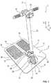
- the electromotive stand-up vehicle 2 shownis suitable and set up for transporting people, in particular on an extensive site or an extensive building complex, such as an airport or a workshop.
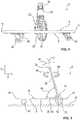
- the standing vehicle 2here has a large-area standing platform 4 with an upper side 6 and an opposite underside 8 ( Fig. 2 ) on.
- the standing platform 4which is roughly rectangular in this exemplary embodiment, is roughly parallel and flat to a base 10 ( Fig. 5 ) arranged.
- the underside 8 of the standing platform 4faces the subsurface 10 here.
- the standing platform 4has two longitudinal sides or side edges 12 and two transverse sides 14 and 16 oriented perpendicular thereto.
- the transverse sides 14, 16here have a reduced length compared to the longitudinal sides 12.
- the front transverse side 14 of the standing vehicle 2is also referred to below as the front or front edge 14.
- the transverse side 16 arranged opposite to thisis correspondingly also referred to as the rear side or rear edge 16.
- the abscissa axis Xis oriented parallel to a longitudinal direction of the vehicle, i.e. parallel to the longitudinal sides, and runs from the rear edge 16 to the front edge 14.
- the ordinate axis Ywhich is perpendicular to this, extends in the transverse direction of the vehicle and is oriented parallel to the transverse sides 14 and 16.
- the application axis Zis oriented perpendicular to the standing platform 4.
- the standing platform 4has a central axis M running parallel to the longitudinal sides 12 as an axis of symmetry. In the area of the front edge 14, a pass-through opening 18, which is completely closed on the circumference, is made in the standing platform 4. The approximately circular lead-through opening 18 is arranged on the central axis M and introduced into the standing platform 4 as an approximately hole-like recess.
- a front wheel 20 of the standing vehicle 2is arranged within the through opening 18.
- the front wheel 20is seated in the feed-through opening 18 in such a way that the Front wheel 20 protrudes at least partially from both the top 6 and the bottom 8 of the standing platform 4.
- the front wheel 20 of the standing vehicle 2is therefore not arranged free-standing on the standing platform 4, but rather embedded in the standing platform 4 itself. Through the through opening 18, the central front wheel 20 is protected by the surrounding standing plate 4, so that the forces that occur in particular do not act on the front wheel 20 in the event of a collision with an obstacle. This improves the stability of a user in the event of an impact, so that particularly safe operation of the standing vehicle 2 is ensured.
- the front wheel 20is mechanically coupled to a handlebar (steering column) 22.
- the handlebar 22has a spring-loaded or damped wheel fork 23, by means of which the front wheel 20 is rotatably mounted.
- the handlebar 22is provided with a handlebar 24 at a (rod) end opposite the front wheel 20.
- the handlebar 22is fastened to the upper side 6 of the standing platform 4 by means of a holder 26.
- the handlebar rod 22is rotatably supported by means of the bracket 26, so that by pivoting the handlebar 24 about an axis of rotation D formed by the handlebar rod 22, the front wheel 20 is also pivoted or guided by a corresponding pivoting or steering angle.
- the front wheel 20is driven or drivable by means of an electric drive or electric motor 28.
- the drive motor 28is designed as a wheel hub motor and as such is at least partially integrated into the front wheel 20 of the standing vehicle 2.
- a vehicle battery(not shown) in the form of an accumulator is integrated in the handlebar 22.
- the handlebar 24has a Rotary handle 30 for controlling and setting the engine power (torque, speed) and thus the vehicle speed.
- the handlebar 22 and thus the front wheel 20 as well as the handlebar 24are held pivotably with respect to the standing platform 4 by means of the holder 26.
- the holder 26here has a fastening plate 32 which is rigidly fastened to the standing platform 4 and has a holding arm 34 which is pivotable with respect to this and which surrounds or surrounds the handlebar 22 in a form-fitting manner.
- the holding arm 34can be released by means of a foot pedal 36 in the position shown in FIG Fig. 1 illustrated upright position of the handlebar 22 can be locked.
- the foot pedal 36When the foot pedal 36 is actuated, the lock is released, as a result of which the holding arm 34 can be pivoted or tilted relative to the fastening plate 32 such that the handlebar 22 can be positioned essentially flat along the central axis M on the upper side 6 of the standing platform 4.
- transport and / or storage of the standing vehicle 2 with a particularly compact installation spaceis possible.
- the upper side 6also referred to below as the standing surface, has two rectangular floor mats 38.
- a userpreferably places one of his feet on each of the floor mats 38.
- the floor mats 38are made of a rubber material and have a diamond-like (standing) profile to improve the user's standing security.
- the standing platform 4has two rear wheels 40 on the underside 8.
- the rear wheels 40have - as in particular in the representations of Fig. 4 and the Fig. 5 can be seen - here, compared to the front wheel 20, a reduced wheel diameter.
- the rear wheels 40are opposite the front wheel 20 along the abscissa axis X towards the rear edge 16 positioned offset on the underside 8.
- the rear wheels 40are also arranged offset laterally to the central axis M along the ordinate axis Y.
- the front wheel 20is designed, for example, with a pneumatic tire, the rear wheels 40 being designed in particular as hard rubber wheels.
- the front wheel 20 and the rear wheels 40form the corners of an isosceles triangle, the central axis M forming the axis of symmetry of the triangle.
- the thigh sides of the trianglethat is, the connecting line between the front wheel 20 and the respective rear wheel 40, each form a tilting axis K1, K2 about which the standing vehicle 2 can tip over.
- the standing vehicle 2has two support elements 42 designed as support wheels.
- the essentially freely pivotable support wheels 42stand up from the underside 8 of the standing platform 4 and are arranged laterally flanking the front wheel 20.
- the support wheels 42are in particular arranged laterally outside the respective tilting line K1 and K2.
- the support wheels 42are arranged radially outside of the tilting lines K1 and K2 with respect to the central axis M, so that the standing platform 4 is reliably supported laterally when it is tilted to the side.
- the front wheel 20 and the two rear wheels 40carry the standing platform 4 and are essentially in physical contact with the ground 10 at all times when the standing vehicle 2 is in operation.
- the support wheels 42have a lower axial axis than the front wheel 20 and the rear wheels 40 Height at the bottom 10. With others In other words, the support wheels 42 essentially do not touch the ground 10. If a certain degree of lateral inclination occurs in relation to the abscissa axis X or the central axis M of the standing platform 4, as is possible, for example, when the standing vehicle 2 is cornering, the support wheel 42 touches the inclined side of the standing platform, i.e. the side of the curve facing longitudinal side 12, the base 10. As a result, the standing platform is laterally supported and reliably protected against tipping over along the tilting lines K1 or K2.
- the pivotability or tiltability of the handlebar 22 or the holding arm 34 about a pivot axis of the holder 26 oriented parallel to the ordinate axis Yis shown schematically by means of a double arrow 44.
- the handlebar 22is approximately parallel to the application axis Z in the upright position and has an acute angle of inclination 46, ie an angle less than 90 °, with respect to the standing platform 4.
- FIG Fig. 5The pivotability about the axis of rotation D implemented by the handlebar 22 is shown in FIG Fig. 5 shown by means of two curved arrows 48.
- the arrows 48are also referred to below as the pivot angle or steering angle.
- the front wheel 20can be pivoted around the axis of rotation D around 360 °.
- the handlebar 22is fastened to the holding arm 34 in such a way that a full-angle rotation of the handlebar 22 and thus of the front wheel 20 is possible.
- This means that an essentially unlimited steering angle 48can be implemented for the front wheel 20 with the handlebar 24, so that the standing vehicle 2 is particularly manoeuvrable.
- the standing vehicle 2 described aboveis particularly suitable and set up for carrying out a method according to the invention.
- the procedure described belowis also different Standing vehicles are transferable and are regarded as an independent invention.
- the steering angle 48 of the front wheel 20 about the axis of rotation D, that is to say about the handlebar 22,is detected.
- rotation angle sensorsare integrated into the handlebar 22, for example.
- the torque and / or the speed of the drive motor 28, that is to say the motor powerare set for controlling the vehicle speed as a function of the detected steering angle 48.
- the torque and vehicle speedare limited as a function of the steering angle.
- the engine power and thereby the vehicle speedare reduced successively or in stages.
- the methodautomatically controls and / or regulates to a low engine torque in the course of reversing, in which the front wheel 20 is pivoted through 180 °. This counteracts excessive starting or accelerating, which improves user comfort and user safety.
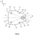
- the schematic and simplified top view of the Fig. 6shows an alternative embodiment of the standing vehicle 2.
- the standing platform 4has an approximately hexagonal cross-sectional shape in the illustrated XY plane.
- the front edge 14here has a shortened side length compared to the rear edge 16.
- the front edge 14ends here in two inclined edges 50 with respect to the central axis M or the abscissa axis X, which run from the front edge 14 to the respective side edge 12.
- the side edges 12run from the rear edge 16 to approximately level with a vehicle center, which is arranged centrally between the front edge 14 and the rear edge 16 along the central axis M, and merge there into the respective inclined edges 50.
- the standing vehicle 2in this embodiment a narrower, in cross-section approximately trapezoidal vehicle front.
- the support wheels or support elements 42are arranged offset along the central axis M towards the rear wheels 40 behind the front wheel 20.
- the support elements 42are further offset laterally from the central axis M and are arranged outside the respective tilting line K1, K2.
- This arrangement of the support elements 42 behind the front wheel 20advantageously simplifies the use of the standing vehicle 2 in the area of steps and thresholds, since when the step or threshold is driven over, the front wheel 20 is first brought up to it.
Landscapes
- Engineering & Computer Science (AREA)
- Mechanical Engineering (AREA)
- Chemical & Material Sciences (AREA)
- Combustion & Propulsion (AREA)
- Transportation (AREA)
- General Engineering & Computer Science (AREA)
- Motorcycle And Bicycle Frame (AREA)
- Automatic Cycles, And Cycles In General (AREA)
- Handcart (AREA)
Description
Translated fromGermanDie Erfindung betrifft ein elektromotorisch angetriebenes Stehfahrzeug für einen Personentransport mit einem elektrischen Antriebsmotor und mit einer Stehplattform. Die Erfindung betrifft weiterhin ein Verfahren zum Betrieb eines derartigen Stehfahrzeugs.The invention relates to an electric motor-driven standing vehicle for transporting people with an electric drive motor and with a standing platform. The invention also relates to a method for operating such a standing vehicle.
Stehfahrzeuge der eingangsgenannten Art sind vergleichsweise einfache Transportmittel, welche gleichzeitig mit Hindernissen und Menschenansammlungen verträglich sind. Derartige Stehfahrzeuge werden insbesondere auf ebenen, befestigten Flächen zur Fortbewegung oder zum Transport von Personen genutzt, und weisen in der Regel zwei oder drei Räder auf. Aufgrund der einfachen Handhabung und flexiblen Einsatzmöglichkeiten sowie dem vergleichsweise geringen Platzbedarf werden derartige Stehfahrzeuge häufig zum Personentransport in weitläufigen Geländen oder Gebäudekomplexen, wie beispielsweise einer Werkshalle oder einem Flughafen, zur Reduzierung von Gehzeiten eingesetzt.Standing vehicles of the type mentioned are comparatively simple means of transport, which are also compatible with obstacles and crowds of people. Such standing vehicles are used in particular on flat, paved surfaces for moving or transporting people, and usually have two or three wheels. Due to the simple handling and flexible application possibilities as well as the comparatively small space requirement, such standing vehicles are often used for the transport of people in extensive areas or building complexes, such as a factory hall or an airport, to reduce walking times.
Bei derartigen Stehfahrzeugen steht ein Benutzer während der Fahrt in der Regel aufrecht auf einer Standfläche einer parallel zu einem Untergrund orientierten Stehplattform. Die Stehplattform ist hierbei in der Regel flach angeordnet. Dies bedeutet, dass die Stehplattform lediglich einen geringen Abstand zum Untergrund aufweist. Dadurch weist das Stehfahrzeug im Betrieb aufgrund des aufrecht stehenden Benutzers einen vergleichsweise hohen Schwerpunkt auf, welcher in der Regel oberhalb der Stehplattform angeordnet ist. Somit besteht im Betrieb eine gewisse Kipp- und somit Unfallgefahr.In such standing vehicles, a user usually stands upright during the journey on a standing surface of a standing platform oriented parallel to a ground. The standing platform is usually arranged flat. This means that the standing platform is only a short distance from the ground. As a result, the standing vehicle has a comparatively high center of gravity during operation due to the upright user, which is usually arranged above the standing platform. This means that there is a certain risk of tipping over and an accident during operation.
Aus der
Aus der
Die
In der
Aus der
In der
Die
Der Erfindung liegt die Aufgabe zugrunde, ein besonders betriebssicheres und für Personen- und Lastentransport geeignetes elektromotorisches Stehfahrzeug anzugeben. Insbesondere soll ein besonders kippsicheres und betriebssicheres Stehfahrzeug angegeben werden, welches insbesondere für den Einsatz in einem weitläufigen Gebäudekomplex oder einem Gelände zur Reduzierung von Gehzeiten geeignet ist. Der Erfindung liegt weiterhin die Aufgabe zugrunde, ein geeignetes Verfahren zum Betrieb eines derartigen Stehfahrzeugs anzugeben.The invention is based on the object of specifying an electromotive standing vehicle that is particularly reliable and suitable for transporting people and loads. In particular, a particularly stable and safe standing vehicle is to be specified, which is particularly suitable for use in a spacious building complex or an area to reduce walking times. The invention is also based on the object of specifying a suitable method for operating such a standing vehicle.
Hinsichtlich des Stehfahrzeugs wird die Aufgabe mit den Merkmalen des Anspruchs 1 und hinsichtlich des Verfahrens mit den Merkmalen des Anspruchs 13 erfindungsgemäß gelöst. Vorteilhafte Ausgestaltungen und Weiterbildungen sind Gegenstand der jeweiligen Unteransprüche.With regard to the standing vehicle, the object is achieved according to the invention with the features of claim 1 and with regard to the method with the features of claim 13. Advantageous refinements and developments are the subject of the respective subclaims.
Das erfindungsgemäße elektromotorisch angetriebene Stehfahrzeug ist für einen Personentransport, insbesondere in einem weitläufigen Gebäudekomplex oder einem weitläufigen Gelände, geeignet und eingerichtet.The electric motor-driven standing vehicle according to the invention is suitable and set up for transporting people, in particular in an extensive building complex or an extensive area.
Das Stehfahrzeug weist einen elektrischen Antriebsmotor und eine Stehplattform auf. Die Stehplattform ist etwa parallel zu einem Untergrund angeordnet und weist eine zum Untergrund orientierte Unterseite sowie eine dieser gegenüberliegend angeordneten Oberseite auf. Die Oberseite ist hierbei zweckmäßigerweise als eine Standfläche für einen Benutzer ausgebildet. Die Standfläche weist beispielsweise Mittel zur verbesserten Standsicherheit, wie beispielsweise ein mattenartiges Gummiprofil oder dergleichen auf.The standing vehicle has an electric drive motor and a standing platform. The standing platform is arranged approximately parallel to a base and has an underside oriented to the base and an upper side arranged opposite it. The upper side is expediently designed as a standing surface for a user. The standing surface has, for example, means for improved stability, such as a mat-like rubber profile or the like.
Entlang einer Mittelachse der Stehplattform ist ein lenkbares Vorderrad angeordnet. Das Vorderrad ist mit einer Lenkerstange (Lenksäule) mit einem Lenker gekoppelt, und mittels dieser um eine durch die Lenkerstange gebildeten Drehachse verschwenkbar. Zur Kopplung der Lenkerstange mit dem Vorderrad weist die Lenkerstange geeigneterweise eine Radgabel auf, welche vorzugsweise mit einer Dämpfung oder Federung zur Verbesserung des Bodenkontakts und des Benutzerkomforts versehen ist.A steerable front wheel is arranged along a central axis of the standing platform. The front wheel is coupled to a handlebar by means of a handlebar (steering column) and can be pivoted by means of this about an axis of rotation formed by the handlebar. For coupling the handlebar to the front wheel, the handlebar suitably has a wheel fork, which is preferably provided with damping or suspension to improve ground contact and user comfort.
Zum Vorderrad beabstandet sind zwei Hinterräder an der Stehplattform angeordnet, welche jeweils seitlich zur Mittelachse versetzt sind. Das Vorderrad und die Hinterräder bilden hierbei geeigneterweise die Ecken eines gleichschenkeligen Dreiecks, wobei die Mittelachse die Symmetrieachse bildet.At a distance from the front wheel, two rear wheels are arranged on the standing platform, which are each offset laterally to the central axis. The front wheel and the rear wheels here suitably form the corners of an isosceles triangle, the central axis forming the axis of symmetry.
In die Stehplattform ist eine umfangsseitig vollständig geschlossene, Durchführöffnung eingebracht. Die Durchführöffnung ist hierbei beispielsweise als eine kreisrunde, lochartige Aussparung in die Stehplattform eingebracht. Im Betrieb des Stehfahrzeugs sitzt das Vorderrad in der Durchführöffnung ein.A feed-through opening that is completely closed on the circumference is made in the standing platform. The lead-through opening is here made, for example, as a circular, hole-like recess in the standing platform. In operation of the standing vehicle the front wheel sits in the opening.
Das Vorderrad ist beidseitig von jeweils mindestens einem Stützelement flankiert. Das oder jedes Stützelement steht hierbei der Unterseite der Stehplattform etwa senkrecht empor.The front wheel is flanked on both sides by at least one support element. The or each support element here stands approximately perpendicularly up on the underside of the standing platform.
Im Gegensatz zum Stand der Technik ist das Vorderrad beziehungsweise die Lenkerstange nicht freistehend an der Stehplattform angeordnet, sondern insbesondere in diese zumindest teilweise eingelassen. Durch die Durchgangsöffnung ist das zentrale Vorderrad beziehungsweise die Lenkerstange von der umgebenden Stehplatte geschützt, sodass bei einem Anprall an einem Hindernis die auftretenden Kräfte nicht auf das Vorderrad und/oder die Lenkerstange einwirken. Mit anderen Worten wirken die Kräfte bei einem Anprall an einem Hindernis insbesondere auf eine Vorderkante der Stehplattform. Dadurch wird die Standsicherheit eines Benutzers bei einem Anprall verbessert, sodass ein besonders sicherer Betrieb des Stehfahrzeugs gewährleistet ist.In contrast to the prior art, the front wheel or the handlebar is not arranged free-standing on the standing platform, but in particular is at least partially embedded in it. Through the through opening, the central front wheel or the handlebar is protected from the surrounding standing plate, so that in the event of a collision with an obstacle, the forces that occur do not act on the front wheel and / or the handlebar. In other words, in the event of a collision with an obstacle, the forces act in particular on a front edge of the standing platform. This improves the stability of a user in the event of an impact, so that particularly safe operation of the standing vehicle is ensured.
Das Vorderrad und die beiden Hinterräder tragen die Stehplattform und befinden sich im Betrieb des Stehfahrzeugs im Wesentlichen zu jedem Zeitpunkt der Fahrt in einem Berührungskontakt mit dem Untergrund. Die Stützelemente weisen zweckmäßigerweise eine im Vergleich zu den Vorder- und Hinterrädern geringere axiale Höhe an der Unterseite auf. Mit anderen Worten berühren die Stützelemente bei einer aufrechten Fahrt auf einem ebenen Untergrund diesen nicht. Dies bedeutet, dass die Stützelemente im Wesentlichen in einem lichten Abstand zum Untergrund angeordnet sind. Tritt ein gewisser Grad an seitlicher Neigung der Stehplattform auf, wie es beispielsweise bei einer Kurvenfahrt möglich ist, berührt das Stützelement an der geneigten Stehplattformseite, also an der der Kurve zugewandten Längsseite, den Untergrund. Dadurch wird die Stehplattform seitlich abgestützt. Somit wird mittels der Stützelemente die Gefahr eines seitlichen (Um-)Kippens im Wesentlichen vollständig behoben oder zumindest wesentlich reduziert. Dadurch weist das Stehfahrzeug im Vergleich zum Stand der Technik eine verbesserte Kippsicherheit oder Kippstabilität auf.The front wheel and the two rear wheels carry the standing platform and, when the standing vehicle is in operation, are essentially in physical contact with the ground at all times during the journey. The support elements expediently have a lower axial height on the underside compared to the front and rear wheels. In other words, when driving upright on a level surface, the support elements do not touch the latter. This means that the support elements are arranged essentially at a clear distance from the ground. If a certain degree of lateral inclination of the standing platform occurs, as is possible, for example, when cornering, the support element touches the ground on the inclined standing platform side, that is to say on the long side facing the curve. This supports the standing platform at the side. Thus, by means of the support elements, the danger a lateral (overturning) tipping essentially completely eliminated or at least significantly reduced. As a result, the standing vehicle has an improved tipping safety or tipping stability compared to the prior art.
Dadurch ist ein besonders geeignetes elektromotorisches Stehfahrzeug realisiert. Insbesondere ist somit ein gewichtsarmes, flexibles Stehfahrzeug für den Personentransport realisiert, welches eine verringerte Unfallgefahr und somit eine erhöhte Arbeitssicherheit aufweist. Das Stehfahrzeug ermöglicht somit eine verbesserte Logistik und eine betriebssichere Reduzierung von Gehzeiten bei weitläufigen Geländen oder Gebäudekomplexen, wie beispielsweise Werkshallen und Werksgeländen sowie Flughäfen.As a result, a particularly suitable electromotive standing vehicle is realized. In particular, a lightweight, flexible standing vehicle for passenger transport is thus implemented, which has a reduced risk of accidents and thus increased occupational safety. The standing vehicle thus enables improved logistics and an operationally reliable reduction in walking times on extensive grounds or building complexes, such as factory halls and factory premises as well as airports.
Durch die Stützelemente ist eine im Vergleich zum Stand der Technik verbreiterte oder großflächigere Stehplattform ermöglicht. Die somit vergrößerte Stehplattform ermöglicht neben einer komfortablen Standfläche für den Benutzer eine zusätzliche Standfläche für einen weiteren Benutzer und/oder eine Stand- oder Abstellfläche für einen stabilen und betriebssicheren Transport von Gegenständen, wie beispielsweise Waren, Taschen und sonstigem Gepäck. Dadurch wird die Flexibilität des Stehfahrzeugs vorteilhaft erhöht.The support elements enable a standing platform that is wider or larger than that of the prior art. The standing platform thus enlarged enables, in addition to a comfortable standing area for the user, an additional standing area for another user and / or a standing or storage area for stable and operationally reliable transport of objects such as goods, bags and other luggage. This advantageously increases the flexibility of the standing vehicle.
Im Nachfolgenden sind Angaben hinsichtlich der Raumrichtungen insbesondere bezüglich eines Koordinatensystems des Stehfahrzeugs (Fahrzeugkoordinatensystem) angegeben.In the following, information is given with regard to the spatial directions, in particular with regard to a coordinate system of the standing vehicle (vehicle coordinate system).
Die Abszissenachse (X-Achse) ist parallel zu einer Fahrzeuglängsrichtung entlang der Mittelachse von den Hinterrädern zu dem Vorderrad orientiert. Die hierzu senkrechte Ordinatenachse (Y-Achse) erstreckt sich in Fahrzeugquerrichtung und ist parallel zur Verbindungslinie der Hinterräder orientiert. Die im Wesentlichen horizontal orientierte Stehplattform ist hierbei in der durch die Abszissen- und Ordinatenachse aufgespannten Ebene (XY-Ebene) angeordnet. Die Applikatenachse (Z-Achse) ist hierbei senkrecht zur Stehplattform orientiert. Im Betrieb des Stehfahrzeugs ist die Lenkerstange insbesondere etwa parallel zur Applikatenachse orientiert.The abscissa axis (X axis) is oriented parallel to a vehicle longitudinal direction along the central axis from the rear wheels to the front wheel. The ordinate axis (Y-axis) perpendicular to this extends in the transverse direction of the vehicle and is oriented parallel to the connecting line of the rear wheels. The essentially horizontally oriented standing platform is here arranged in the plane spanned by the abscissa and ordinate axis (XY plane). The application axis (Z-axis) is oriented perpendicular to the standing platform. When the standing vehicle is in operation, the handlebar is in particular oriented approximately parallel to the application axis.
Die dem Vorderrad zugewandte Querseite der Stehplattform ist nachfolgend insbesondere als Vorderseite oder Vorderkante bezeichnet, wobei die gegenüberliegend angeordnete und den Hinterrädern zugewandte Querseite der Stehplattform entsprechend als Hinterseite oder Hinterkante bezeichnet ist. Die Längsseiten der Stehplattform sind nachfolgend auch als Seitenkanten bezeichnet.The transverse side of the standing platform facing the front wheel is referred to below in particular as the front side or front edge, the opposite side of the standing platform facing the rear wheels being correspondingly referred to as the rear side or rear edge. The long sides of the standing platform are also referred to below as side edges.
In einer vorteilhaften Ausführung ist das oder jedes Stützelement jeweils seitlich außerhalb einer zwischen dem Vorderrad und dem jeweiligen Hinterrad verlaufenden Kipplinie an der Unterseite positioniert. Die Kipplinie entspricht hierbei einer Kippachse, um welche das Stehfahrzeug bei einer seitlichen Neigung kippen würde. Die Stützelemente sind bezogen auf die Mittelachse radial außerhalb der beiden Kipplinien angeordnet, sodass die Stehplattform und somit das Stehfahrzeug bei einer seitlichen Neigung zuverlässig seitlich abgestützt wird. Dadurch ist eine besonders hohe Kippsicherheit des Stehfahrzeugs erreicht.In an advantageous embodiment, the or each support element is positioned laterally outside a tilting line running between the front wheel and the respective rear wheel on the underside. The tilting line corresponds to a tilting axis about which the standing vehicle would tilt in the event of a lateral inclination. The support elements are arranged radially outside of the two tilting lines in relation to the central axis, so that the standing platform and thus the standing vehicle are reliably supported laterally in the event of a lateral inclination. This achieves a particularly high level of security against tipping over for the standing vehicle.
In einer geeigneten Ausführungsform sind die Stützelemente hierbei im Bereich des zentralen Vorderrads beziehungsweise im vorderen Bereich der Stehplattform angeordnet. Durch die beabstandeten Hinterräder im hinteren Bereich der Stehplattform und die vorderseitig beabstandet angeordneten Stützelemente neben dem Vorderrad ist ein besonders hoher und zuverlässiger Kippschutz des Stehfahrzeugs realisiert.In a suitable embodiment, the support elements are arranged in the area of the central front wheel or in the front area of the standing platform. The spaced-apart rear wheels in the rear area of the standing platform and the support elements, which are spaced apart on the front side next to the front wheel, provide a particularly high and reliable tilt protection of the standing vehicle.
Die Stützelemente sind als Stützräder ausgebildet. Die Stützräder sind hierbei vorzugsweise frei schwenkbar am vorderen Ende der Stehplattform angeordnet. Dadurch sind besonders geeignete und zweckmäßige Stützelemente realisiert, welche besonders flexibel auf einem jeweiligen Untergrund abstützen können.The support elements are designed as support wheels. The support wheels are preferably arranged in such a way that they can pivot freely at the front end of the standing platform. This makes them particularly suitable and expedient Realized support elements, which can support particularly flexibly on a respective substrate.
In einer möglichen Weiterbildung sind die Stützelemente entlang der Mittelachse zu den Hinterrädern hin versetzt hinter dem Vorderrad angeordnet. Dadurch wird der Einsatz des Stehfahrzeugs im Bereich von Stufen und Schwellen vorteilhaft vereinfacht, da somit bei einem Überfahren der Stufe oder der Schwelle zuerst das Vorderrad an diese herangeführt wird. Gleichzeitig ist weiterhin ein hoher Kippschutz gewährleistet, sodass ein besonders einfaches und sicheres Überfahren von Schwellen und Stufen möglich ist.In a possible development, the support elements are arranged behind the front wheel offset along the central axis towards the rear wheels. This advantageously simplifies the use of the standing vehicle in the area of steps and thresholds, since when the step or threshold is driven over, the front wheel is first brought up to it. At the same time, a high level of anti-tip protection is still guaranteed, so that it is particularly easy and safe to drive over thresholds and steps.
In einer zweckmäßigen Ausgestaltung ist das Vorderrad mittels des Antriebsmotors angetrieben. Dadurch ist ein besonders zweckmäßiger Antrieb des Stehfahrzeugs realisiert. Hierbei ist es beispielsweise denkbar, dass der Lenker mit einem Drehgriff zur einfachen Steuerung der Motorleistung und somit der Fahrzeuggeschwindigkeit versehen ist. Somit wird keine weitere Kupplung oder Gangschaltung benötigt.In an expedient embodiment, the front wheel is driven by means of the drive motor. This realizes a particularly expedient drive for the standing vehicle. Here it is conceivable, for example, that the handlebar is provided with a twist grip for simple control of the engine output and thus the vehicle speed. This means that no further clutch or gear shift is required.
In einer vorteilhaften Ausführung ist der Antriebsmotor als ein Radnabenmotor des Vorderrads ausgebildet. Mit anderen Worten ist der Elektro- oder Antriebsmotor direkt in dem Vorderrad des Stehfahrzeugs eingebaut oder integriert. Dadurch ist ein besonders zweckmäßiger und bauraumkompakter Antriebsmotor realisiert.In an advantageous embodiment, the drive motor is designed as a wheel hub motor for the front wheel. In other words, the electric or drive motor is installed or integrated directly into the front wheel of the standing vehicle. As a result, a particularly expedient and compact drive motor is realized.
In einer besonders bevorzugten Ausgestaltung ist das innerhalb der Durchgangsöffnung angeordnete Vorderrad mittels des Lenkers um 360° verschwenkbar. Mit anderen Worten ist durch den Lenker und die Lenkerstange ein im Wesentlichen unbegrenzter Lenkwinkel für das Vorderrad realisiert. Dadurch wird einerseits eine größtmögliche Wendigkeit des Stehfahrzeugs gewährleistet. Andererseits ist es somit insbesondere möglich, dass das Stehfahrzeug auch ohne Schaltung rückwärts bewegt werden kann, also die Fahrt- oder Bewegungsrichtung umgedreht wird, indem der Lenker - und somit das Vorderrad - um 180° verschwenkt wird. Somit ist ein besonders geeignetes Stehfahrzeug realisiert.In a particularly preferred embodiment, the front wheel arranged within the through opening can be pivoted through 360 ° by means of the handlebar. In other words, a substantially unlimited steering angle for the front wheel is implemented by the handlebar and the handlebar. On the one hand, this ensures the greatest possible maneuverability of the standing vehicle. On the other hand, it is thus possible in particular for the standing vehicle to be moved backwards even without a gearshift can, i.e. the direction of travel or movement is reversed by pivoting the handlebar - and thus the front wheel - by 180 °. A particularly suitable standing vehicle is thus implemented.
In einer zweckmäßigen Weiterbildung ist eine Fahrzeugbatterie zur Energieversorgung des Antriebsmotors in die Lenkerstange integriert. Die beispielsweise als Akkumulator ausgeführte Fahrzeugbatterie ist somit besonders platzsparend am Stehfahrzeug angeordnet, sodass beispielsweise zusätzlicher Bauraum im Bereich der Stehplattform bewirkt wird. Die Integrierung der Fahrzeugbatterie in die Lenkerstange ist hierbei insbesondere bei einer Weiterbildungsform mit einem als Radnabenmotor ausgeführten Antriebsmotor des Vorderrads vorteilhaft, da somit eine besonders einfache und materialsparende Kabelführung realisiert ist.In an expedient development, a vehicle battery for supplying energy to the drive motor is integrated in the handlebar. The vehicle battery, for example designed as an accumulator, is thus arranged in a particularly space-saving manner on the standing vehicle, so that additional installation space is created in the area of the standing platform, for example. The integration of the vehicle battery in the handlebar is particularly advantageous in a further development with a drive motor of the front wheel designed as a wheel hub motor, since a particularly simple and material-saving cable routing is implemented.
In einer alternativen Weiterbildungsform ist die Fahrzeugbatterie beispielsweise in der Stehplattform integriert.In an alternative form of development, the vehicle battery is integrated in the standing platform, for example.
In einer geeigneten Ausbildung ist die Lenkerstange verschwenkbar gegenüber der Stehplattform. Mit anderen Worten ist die Lenkerstange klappbar an der Stehplattform befestigt, sodass bei Bedarf das Stehfahrzeug bauraumkompakt zusammengeklappt werden kann. Hierzu wird die Lenkerstange um eine Schwenkachse verschwenkt, welche im Wesentlichen parallel zu der Ordinatenachse des Stehfahrzeugs orientiert ist. Dadurch sind ein besonders bauraumkompakter Transport und/oder eine bauraumkompakte Lagerung des Stehfahrzeugs möglich. In einer geeigneten Ausbildungsform sind somit insbesondere die Lenkerstange und der Antriebsmotor gemeinsam verschwenkbar.In a suitable embodiment, the handlebar can be pivoted relative to the standing platform. In other words, the handlebar is foldably attached to the standing platform, so that, if necessary, the standing vehicle can be folded up in a compact manner. For this purpose, the handlebar is pivoted about a pivot axis which is oriented essentially parallel to the ordinate axis of the standing vehicle. As a result, transport and / or storage of the standing vehicle with a particularly compact installation space is possible. In a suitable embodiment, the handlebar and the drive motor in particular can be pivoted together.
Ein zusätzlicher oder weiterer Aspekt der Erfindung betrifft ein Verfahren zum Betrieb eines elektromotorischen Stehfahrzeugs.An additional or further aspect of the invention relates to a method for operating an electromotive standing vehicle.
Verfahrensgemäß wird ein Verschwenkwinkel des Vorderrads um die Drehachse, insbesondere um die Lenkerstange, erfasst. Mit anderen Worten wird ein Lenkwinkel des Stehfahrzeugs erfasst. Hierzu sind beispielsweise Drehwinkelsensoren in die Lenkerstange integriert.According to the method, a pivot angle of the front wheel about the axis of rotation, in particular about the handlebar, is detected. In other words, a steering angle of the standing vehicle is detected. For this purpose, for example, rotation angle sensors are integrated into the handlebar.
Verfahrensgemäß werden ein Drehmoment und/oder die Drehzahl des Antriebsmotors, also die Motorleistung, zur Steuerung der Fahrzeuggeschwindigkeit in Abhängigkeit des erfassten Verschwenkwinkels eingestellt.According to the method, a torque and / or the speed of the drive motor, that is to say the motor power, are set for controlling the vehicle speed as a function of the detected pivoting angle.
Durch das erfindungsgemäße Verfahren wird somit eine verschwenk- oder lenkwinkelabhängige Begrenzung des Drehmoments und der Fahrzeuggeschwindigkeit realisiert. Bei einem zunehmend größeren Lenkwinkel wird somit die Motorleistung und dadurch die Fahrzeuggeschwindigkeit sukzessive oder stufenweise reduziert, sodass eine Unfallgefahr aufgrund einer fehlerhaften Benutzung vorteilhaft und auf einfache Art und Weise vermieden wird. Dadurch wird das Stehfahrzeug beispielsweise bei einer engen Kurvenfahrt - und entsprechend großem Lenkwinkel - selbsttätig oder automatisch abgebremst, sodass eine Kipp- oder Unfallgefahr zuverlässig reduziert wird.The method according to the invention thus realizes a limitation of the torque and the vehicle speed as a function of the pivoting or steering angle. With an increasingly larger steering angle, the engine power and thereby the vehicle speed are reduced successively or in stages, so that the risk of an accident due to incorrect use is advantageously and easily avoided. As a result, the standing vehicle is automatically or automatically braked when cornering tightly - and with a correspondingly large steering angle - so that the risk of tipping over or an accident is reliably reduced.
Das Verfahren ist hierbei insbesondere für ein vorstehend beschriebenes Stehfahrzeug mit einem 360°-verschwenkbaren Vorderrad geeignet. Durch das Verfahren wird im Zuge eines Rückwärtsfahrens, bei welchem das Vorderrad insbesondere um 180° verschwenkt ist, automatisch auf ein niedriges Motordrehmoment gesteuert und/oder geregelt. Dadurch wird einem ungewünschten zu schnellen Anfahren oder Beschleunigen entgegengewirkt, wodurch der Benutzerkomfort sowie die Benutzersicherheit verbessert werden.The method is particularly suitable for a standing vehicle described above with a 360 ° pivotable front wheel. The method automatically controls and / or regulates to a low engine torque in the course of reversing, in which the front wheel is pivoted in particular by 180 °. This counteracts an undesirable excessive acceleration or acceleration, which improves user comfort and user safety.
Vorteilhafterweise weist das Stehfahrzeug hierbei einen Controller, also ein Steuergerät, auf, welcher/s zur Durchführung des vorstehend beschriebenen Verfahrens geeignet und eingerichtet ist.The standing vehicle advantageously has a controller, that is to say a control device, which is suitable and set up to carry out the method described above.
Der Controller ist hierbei allgemein programm- und/oder schaltungstechnisch zur Durchführung des vorstehend beschriebenen erfindungsgemäßen Verfahrens eingerichtet. Der Controller ist somit konkret dazu eingerichtet, mittels eines Sensors den Verschwenk- oder Lenkwinkel des Stehfahrzeugs zu erfassen, und anhand des erfassten Winkels das Motordrehmoment und/oder die Motordrehzahl des Antriebsmotors einzustellen.The controller is generally set up in terms of programming and / or circuitry to carry out the method according to the invention described above. The controller is thus specifically set up to detect the pivoting or steering angle of the standing vehicle by means of a sensor and to set the engine torque and / or the engine speed of the drive motor on the basis of the detected angle.
In bevorzugter Ausgestaltung ist der Controller zumindest im Kern durch einen Microcontroller mit einem Prozessor und mit einem Datenspeicher gebildet, in dem die Funktionalität zur Durchführung des erfindungsgemäßen Verfahrens in Form einer Betriebssoftware (Firmware) programmtechnisch implementiert ist, sodass das Verfahren - gegebenenfalls in Interaktion mit einem Kraftfahrzeugnutzer - bei Ausführung der Betriebssoftware in dem Microcontroller automatisch durchgeführt wird.In a preferred embodiment, the controller is at least essentially formed by a microcontroller with a processor and with a data memory, in which the functionality for performing the method according to the invention is implemented in the form of operating software (firmware) so that the method - possibly in interaction with a Motor vehicle user - is carried out automatically when the operating software is executed in the microcontroller.
Der Controller kann im Rahmen der Erfindung alternativ aber auch durch ein nicht programmierbares elektronisches Bauteil, z.B. einen anwendungsspezifischen Schaltkreis (ASIC), gebildet sein, in dem die Funktionalität zur Durchführung des erfindungsgemäßen Verfahrens mit schaltungstechnischen Mitteln implementiert ist.Within the scope of the invention, however, the controller can alternatively also be formed by a non-programmable electronic component, e.g. an application-specific circuit (ASIC), in which the functionality for carrying out the method according to the invention is implemented using circuitry.
In einer möglichen Ausführungsform ist es beispielsweise denkbar, dass der Controller Teil einer den Elektro- oder Antriebsmotor steuernden und/oder regelnden Motorelektronik ist.In one possible embodiment, it is conceivable, for example, that the controller is part of an electronic engine that controls and / or regulates the electric or drive motor.
In einer denkbaren Weiterbildungsform weist der Controller beispielsweise eine Schnittstelle zur insbesondere drahtlosen signaltechnischen Kopplung mit einem Smart Device, wie beispielsweise einem Smartphone oder einem Tabletcomputer, auf. Insbesondere ist hierbei ein Positionssensor, wie beispielsweise ein GPS (Global Positioning System) oder ein WLAN basierter Sensor vorgesehen, welcher die Position des Stehfahrzeugs auf einem Gelände oder innerhalb eines Gebäudekomplexes erfasst.In a conceivable further development, the controller has, for example, an interface for, in particular, wireless signal-technical coupling with a smart device, such as a smartphone or a tablet computer. In particular, a position sensor such as a GPS (Global Positioning System) or a WLAN-based sensor is provided, which detects the position of the standing vehicle on a site or within a building complex.
Hierbei ist es beispielsweise denkbar, dass innerhalb des Geländes oder Gebäudekomplexes unterschiedliche Bereiche oder Zonen bestimmt werden, denen ein jeweiliger maximaler Geschwindigkeitswert zugeordnet ist. Diese jeweiligen Geschwindigkeitswerte sind hierbei beispielsweise in einem Speicher des Controllers hinterlegt, wobei das maximale Drehmoment, und somit die maximale Fahrzeuggeschwindigkeit, mittels des Positionssensors in Abhängigkeit des Bereichs oder der Zone geregelt wird, in dem sich das Stehfahrzeug aktuell befindet. Mit anderen Worten kann ein Benutzer in einer solchen (Geschwindigkeits-)Zone lediglich mit einer vorgegeben Maximal- oder Höchstgeschwindigkeit fahren. Dadurch ist es beispielsweise möglich, in Bereich von Kreuzungen, unübersichtlichen Stellen oder Ladezonen eine automatische Geschwindigkeitsreduzierung des Stehfahrzeugs zu bewirken. Beispielsweise wird hierbei die maximale Fahrzeuggeschwindigkeit von 20 km/h auf 6 km/h reduziert. Durch diese Weiterbildungsform mit Geschwindigkeitszonen wird die Unfallgefahr wesentlich reduziert und somit eine ungewünschte Geschwindigkeitsüberschreitung des Benutzers vermieden.Here it is conceivable, for example, that different areas or zones are determined within the site or building complex, to which a respective maximum speed value is assigned. These respective speed values are stored in a memory of the controller, for example, the maximum torque, and thus the maximum vehicle speed, being regulated by means of the position sensor as a function of the area or zone in which the standing vehicle is currently located. In other words, a user in such a (speed) zone can only drive at a predetermined maximum or maximum speed. This makes it possible, for example, to automatically reduce the speed of the standing vehicle in the area of intersections, blind spots or loading zones. For example, the maximum vehicle speed is reduced from 20 km / h to 6 km / h. This form of further training with speed zones significantly reduces the risk of accidents and thus prevents the user from exceeding the speed undesirably.
In einer ebenso denkbaren Weiterbildungsform weist das Stehfahrzeug zusätzlich oder alternativ Umgebungssensoren, wie beispielsweise optische Kameras oder Näherungssensoren, zur Erfassung der Fahrzeugumgebung auf. Die Umgebungssensoren sind hierbei beispielsweise derart mit dem Controller gekoppelt, dass dieser die Fahrzeuggeschwindigkeit und/oder die Bewegungs- beziehungsweise Lenkrichtung in Abhängigkeit der Sensorsignale steuert. Dadurch ist es beispielsweise denkbar, dass das Stehfahrzeug mit Fahrtunterstützungssystemen, zum Beispiel mit einem Spurhaltesystem oder dergleichen, ausgestattet ist. Insbesondere ist das Stehfahrzeug für ein selbsttätiges oder automatisches Fahren auf dem Gelände oder in dem Gebäudekomplex geeignet und eingerichtet. Durch ein solches autonom bewegbares Stehfahrzeug ist es beispielsweise möglich, dass das Stehfahrzeug selbstständig zu häufig genutzten Orten, wie beispielsweise einer Ladestation zur Aufladung des elektrischen Energiespeichers, oder einem Werkseingang, fährt. Dadurch wird der Benutzerkomfort weiter verbessert.In an equally conceivable further development, the standing vehicle additionally or alternatively has environmental sensors, such as optical cameras or proximity sensors, for detecting the vehicle surroundings. The environmental sensors are for example coupled to the controller in such a way that the controller controls the vehicle speed and / or the direction of movement or steering as a function of the sensor signals. As a result, it is conceivable, for example, that the standing vehicle is equipped with driving support systems, for example with a lane keeping system or the like. In particular is the standing vehicle is suitable and set up for independent or automatic driving on the site or in the building complex. Such an autonomously movable standing vehicle makes it possible, for example, for the standing vehicle to drive independently to frequently used locations, such as a charging station for charging the electrical energy store, or a factory entrance. This further improves user comfort.
Nachfolgend sind Ausführungsbeispiele der Erfindung anhand einer Zeichnung näher erläutert. Darin zeigen:
- Fig. 1
- in perspektivischer Darstellung ein elektromotorisches Stehfahrzeug,
- Fig. 2
- in perspektivischer Darstellung das Stehfahrzeug mit Blick auf eine (Fahrzeug-)Unterseite,
- Fig. 3
- in schematischer Draufsicht die Unterseite des Stehfahrzeugs,
- Fig. 4
- in perspektivischer Darstellung das Stehfahrzeug mit Blick auf eine Vorderseite,
- Fig. 5
- das Stehfahrzeug in schematischer Seitendarstellung, und
- Fig. 6
- in schematischer Draufsicht die Unterseite des Stehfahrzeugs in einer alternativen Ausführungsform.
- Fig. 1
- a perspective view of an electric motorized standing vehicle,
- Fig. 2
- a perspective view of the standing vehicle with a view of a (vehicle) underside,
- Fig. 3
- a schematic top view of the underside of the standing vehicle,
- Fig. 4
- in a perspective view of the standing vehicle with a view of a front side,
- Fig. 5
- the standing vehicle in a schematic side view, and
- Fig. 6
- in a schematic plan view the underside of the standing vehicle in an alternative embodiment.
Einander entsprechende Teile und Größen sind in allen Figuren stets mit den gleichen Bezugszeichen versehen.Corresponding parts and sizes are always provided with the same reference symbols in all figures.
Das in der
Die in diesem Ausführungsbeispiel etwa rechteckige Stehplattform 4 ist etwa parallel und flach zu einem Untergrund 10 (
Im Nachfolgenden sind Angaben hinsichtlich der Raumrichtungen insbesondere in einem Koordinatensystem des Stehfahrzeugs (Fahrzeugkoordinatensystem) angegeben.In the following, information is given with regard to the spatial directions, in particular in a coordinate system of the standing vehicle (vehicle coordinate system).
Die Abszissenachse X ist parallel zu einer Fahrzeuglängsrichtung, also parallel zu den Längsseiten orientiert und verläuft von der Hinterkante 16 zur Vorderkante 14. Die hierzu senkrechte Ordinatenachse Y erstreckt sich in Fahrzeugquerrichtung und ist parallel zu den Querseiten 14 und 16 orientiert. Die Applikatenachse Z ist hierbei senkrecht zur Stehplattform 4 orientiert.The abscissa axis X is oriented parallel to a longitudinal direction of the vehicle, i.e. parallel to the longitudinal sides, and runs from the
Die Stehplattform 4 weist eine parallel zu den Längsseiten 12 verlaufende Mittelachse M als Symmetrieachse auf. Im Bereich der Vorderkante 14 ist eine umfangsseitig vollständig geschlossene Durchführöffnung 18 in die Stehplattform 4 eingebracht. Die etwa kreisrunde Durchführöffnung 18 ist auf der Mittelachse M angeordnet und als eine etwa lochartige Aussparung in die Stehplattform 4 eingebracht.The standing
In dem Ausführungsbeispiel der
Das Vorderrad 20 des Stehfahrzeugs 2 ist somit nicht freistehend an der Stehplattform 4 angeordnet, sondern in die Stehplattform 4 selbst eingelassen. Durch die Durchgangsöffnung 18 ist das zentrale Vorderrad 20 durch die umgebende Stehplatte 4 geschützt, sodass bei einem Anprall an einem Hindernis die auftretenden Kräfte insbesondere nicht auf das Vorderrad 20 einwirken. Dadurch wird die Standsicherheit eines Benutzers bei einem Anprall verbessert, sodass ein besonders sicherer Betrieb des Stehfahrzeugs 2 gewährleistet ist.The
Das Vorderrad 20 ist mechanisch mit einer Lenkerstange (Lenksäule) 22 gekoppelt. Hierzu weist die Lenkerstange 22 eine gefederte oder gedämpfte Radgabel 23 auf, mittels welcher das Vorderrad 20 drehbar eingefasst ist. Die Lenkerstange 22 ist hierbei an einem dem Vorderrad 20 gegenüberliegenden (Stangen-)Ende mit einem Lenker 24 versehen. Im Bereich der Radgabel 23, also an einem dem Vorderrad 20 zugewandten (Stangen-)Ende, ist die Lenkerstange 22 mittels einer Halterung 26 an der Oberseite 6 der Stehplattform 4 befestigt. Die Lenkerstange 22 ist hierbei mittels der Halterung 26 drehbar gelagert, sodass durch ein Verschwenken des Lenkers 24 um eine durch die Lenkerstange 22 gebildete Drehachse D, das Vorderrad 20 um einen entsprechenden Verschwenk- oder Lenkwinkel mit verschwenkt oder geführt wird.The
Das Vorderrad 20 ist mittels eines elektrischen Antriebs- oder Elektromotors 28 angetrieben oder antreibbar. Der Antriebsmotor 28 ist hierbei als ein Radnabenmotor ausgeführt, und als solcher zumindest teilweise in das Vorderrad 20 des Stehfahrzeugs 2 integriert. In dem Ausführungsbeispiel der
Die Lenkerstange 22 und somit das Vorderrad 20 sowie der Lenker 24 sind mittels der Halterung 26 verschwenkbar gegenüber der Stehplattform 4 gehalten. Die Halterung 26 weist hierbei eine starr an der Stehplattform 4 befestigte Befestigungsplatte 32 mit einem gegenüber dieser verschwenkbaren Haltearm 34 auf, welcher die Lenkerstange 22 formschlüssig umgreift oder einfasst.The
Der Haltearm 34 ist mittels eines Fußpedals 36 lösbar in der in
Im Bereich der Hinterkante 16 weist die nachfolgend auch als Standfläche bezeichnete Oberseite 6 zwei rechteckige Fußmatten 38 auf. Im Betrieb platziert ein Benutzer hierbei vorzugsweise jeweils einen seiner Füße auf jeweils einer der Fußmatten 38. Die Fußmatten 38 sind aus einem Gummimaterial hergestellt und weisen ein rautenartiges (Stand-)Profil zur Verbesserung der Standsicherheit des Benutzers auf.In the area of the
Wie in den Darstellungen der
In dem dargestellten Ausführungsbeispiel ist das Vorderrad 20 beispielsweise mit einem pneumatischen Reifen ausgeführt, wobei die Hinterräder 40 insbesondere als Hartgummi-Räder ausgebildet sind.In the exemplary embodiment shown, the
Wie insbesondere in der
Zur Verbesserung der Kippsicherheit und zur Reduzierung der Unfallgefahr weist das Stehfahrzeug 2 zwei als Stützräder ausgeführte Stützelemente 42 auf. Die im Wesentlichen frei schwenkbaren Stützräder 42 stehen hierbei der Unterseite 8 der Stehplattform 4 empor und sind seitlich flankierend zum Vorderrad 20 angeordnet. Wie insbesondere in der schematischen und vereinfachten Darstellung der
Das Vorderrad 20 und die beiden Hinterräder 40 tragen die Stehplattform 4 und befinden sich im Betrieb des Stehfahrzeugs 2 im Wesentlichen zu jedem Zeitpunkt in einem Berührungskontakt mit dem Untergrund 10. Die Stützräder 42 weisen eine im Vergleich zu dem Vorderrad 20 und den Hinterrädern 40 geringere axiale Höhe an der Unterseite 10 auf. Mit anderen Worten berühren die Stützräder 42 den Untergrund 10 im Wesentlichen nicht. Tritt ein gewisser Grad an seitlicher Neigung, bezogen auf die Abszissenachse X beziehungsweise auf die Mittelachse M, der Stehplattform 4 auf, wie es beispielsweise bei einer Kurvenfahrt des Stehfahrzeugs 2 möglich ist, berührt das Stützrad 42 an der geneigten Stehplattformseite, also an der der Kurve zugewandten Längsseite 12, den Untergrund 10. Dadurch wird die Stehplattform seitlich abgestützt und vor einem Umkippen entlang der Kipplinien K1 beziehungsweise K2 zuverlässig geschützt.The
In der schematischen und vereinfachten Seitendarstellung der
Die Verschwenkbarkeit um die durch die Lenkerstange 22 realisierte Drehachse D ist in der
Das vorstehend beschriebene Stehfahrzeug 2 ist insbesondere zur Durchführung eines erfindungsgemäßen Verfahrens geeignet und eingerichtet. Das nachfolgend beschriebene Verfahren ist jedoch auch auf andersartige Stehfahrzeuge übertragbar und wird als eigenständige Erfindung angesehen.The standing
Verfahrensgemäß wird hierbei der Lenkwinkel 48 des Vorderrads 20 um die Drehachse D, also um die Lenkerstange 22, erfasst. Hierzu sind beispielsweise Drehwinkelsensoren in die Lenkerstange 22 integriert. Verfahrensgemäß werden das Drehmoment und/oder die Drehzahl des Antriebsmotors 28, also die Motorleistung, zur Steuerung der Fahrzeuggeschwindigkeit in Abhängigkeit des erfassten Lenkwinkels 48 eingestellt. Dadurch ist eine lenkwinkelabhängige Begrenzung des Drehmoments und der Fahrzeuggeschwindigkeit realisiert. Bei einem zunehmend größeren Lenkwinkel 48 wird somit die Motorleistung und dadurch die Fahrzeuggeschwindigkeit sukzessive oder stufenweise reduziert.According to the method, the
Durch das Verfahren wird im Zuge eines Rückwärtsfahrens, bei welchem das Vorderrad 20 um 180° verschwenkt ist, automatisch auf ein niedriges Motordrehmoment gesteuert und/oder geregelt. Dadurch wird einem zu schnellen Anfahren oder Beschleunigen entgegengewirkt, wodurch der Benutzerkomfort sowie die Benutzersicherheit verbessert werden.The method automatically controls and / or regulates to a low engine torque in the course of reversing, in which the
Die schematische und vereinfachte Draufsicht der
In diesem Ausführungsbeispiel sind die Stützräder oder Stützelemente 42 entlang der Mittelachse M zu den Hinterrädern 40 hin versetzt hinter dem Vorderrad 20 angeordnet. Die Stützelemente 42 sind hierbei weiterhin seitlich von der Mittelachse M versetzt und außerhalb der jeweiligen Kipplinie K1, K2 angeordnet. Durch diese Anordnung der Stützelemente 42 hinter dem Vorderrad 20 wird der Einsatz des Stehfahrzeugs 2 im Bereich von Stufen und Schwellen vorteilhaft vereinfacht, da somit bei einem Überfahren der Stufe oder der Schwelle zuerst das Vorderrad 20 an diese herangeführt wird.In this exemplary embodiment, the support wheels or support
Die Erfindung ist nicht auf das vorstehend beschriebene Ausführungsbeispiel beschränkt. Vielmehr können auch andere Varianten der Erfindung von dem Fachmann hieraus abgeleitet werden, ohne den Gegenstand der Erfindung zu verlassen. Insbesondere sind ferner alle im Zusammenhang mit dem Ausführungsbeispiel beschriebenen Einzelmerkmale auch auf andere Weise miteinander kombinierbar, ohne den Gegenstand der Erfindung zu verlassen, soweit diese Kombinationen dem Schutzumfang der nachfolgenden Ansprüche entsprechen.The invention is not restricted to the exemplary embodiment described above. Rather, other variants of the invention can also be derived therefrom by the person skilled in the art without departing from the subject matter of the invention. In particular, all of the individual features described in connection with the exemplary embodiment can also be combined with one another in other ways without departing from the subject matter of the invention, provided that these combinations correspond to the scope of protection of the following claims.
- 22
- StehfahrzeugStanding vehicle
- 44th
- StehplattformStanding platform
- 66th
- Oberseite/StandflächeTop side / standing area
- 88th
- Unterseitebottom
- 1010
- UntergrundUnderground
- 1212th
- Längsseite/SeitenkanteLong side / side edge
- 1414th
- Querseite/Vorderkante/VorderseiteShort side / leading edge / front side
- 1616
- Querseite/Hinterkante/HinterseiteTransverse side / trailing edge / rear side
- 1818th
- DurchführöffnungFeed-through opening
- 2020th
- VorderradFront wheel
- 2222nd
- LenkerstangeHandlebar
- 2323
- RadgabelWheel fork
- 2424
- LenkerHandlebars
- 2626th
- Halterungbracket
- 2828
- AntriebsmotorDrive motor
- 3030th
- DrehgriffTwist grip
- 3232
- BefestigungsplatteMounting plate
- 3434
- HaltearmHolding arm
- 3636
- FußpedalFoot pedal
- 3838
- FußmatteDoormat
- 4040
- HinterradRear wheel
- 4242
- Stützelement/StützradSupport element / support wheel
- 4444
- DoppelpfeilDouble arrow
- 4646
- NeigungswinkelTilt angle
- 4848
- Pfeil/Verschwenkwinkel/LenkwinkelArrow / swivel angle / steering angle
- 5050
- SchrägkanteBeveled edge
- MM.
- MittelachseCentral axis
- DD.
- DrehachseAxis of rotation
- XX
- AbszissenachseAbscissa axis
- YY
- OrdinatenachseOrdinate axis
- ZZ
- ApplikatenachseApplication axis
- K1, K2K1, K2
- KippachseTilt axis
Claims (13)
- Standing vehicle (2) which is driven by electric motor for personal transport, having an electric drive motor (28) and a plate-shaped standing platform (4) with a front wheel (20), which is arranged along a centre axis (M) of the standing platform (4), with a handlebar rod (22), which is coupled to the said front wheel (20), with a handlebar (24) for pivoting the front wheel (20) about a rotational axis (D) which is formed by way of the handlebar rod (22), and with two rear wheels (40) which are spaced apart from the front wheel (20) and are arranged in each case offset laterally with respect to the centre axis (M),- the standing platform (4) having an upper side (6) as standing area and a lower side (8) which is arranged opposite the said upper side (6) and faces an underlying surface (10),- a passage opening (18) which is closed completely on the circumferential side being made in the standing platform (4), in which the front wheel (20) is seated,- the front wheel (20) being flanked on both sides by in each case at least one supporting element (42) which rises up from the lower side (8) of the standing platform (4),- the supporting elements (42) being configured as supporting wheels,characterized in that
the supporting elements (42) and the rear wheels (40) are arranged on the lower side (8) of the standing platform (4) . - Standing vehicle (2) according to Claim 1,
characterized
in that the supporting elements (42) are positioned on the lower side (8) in each case laterally outside a tilting line (K1, K2) which runs between the front wheel (20) and the respective rear wheel (40). - Standing vehicle (2) according to either of Claims 1 and 2,
characterized
in that the supporting elements (42) are arranged behind the front wheel (20) in a manner which is offset along the centre axis (M) towards the rear wheels (40). - Standing vehicle (2) according to one of Claims 1 to 3,
characterized
in that the front wheel (20) is driven by means of the drive motor (28). - Standing vehicle (2) according to Claim 4,
characterized
in that the drive motor (28) is configured as a wheel hub motor of the front wheel (20). - Standing vehicle (2) according to one of Claims 1 to 5,
characterized
in that the front wheel (20) which is arranged within the through opening (18) can be pivoted by 360° by means of the handlebar (24). - Standing vehicle (2) according to one of Claims 1 to 6,
characterized
in that a vehicle battery for the power supply of the drive motor (28) is integrated into the handlebar rod (22) . - Standing vehicle (2) according to one of Claims 1 to 7,
characterized
in that the handlebar rod (22) can be pivoted with respect to the standing plate (4). - Standing vehicle (2) according to one of Claims 1 to 8,
characterized
in that the supporting elements (42) can be pivoted freely. - Standing vehicle (2) according to one of Claims 1 to 9,
characterized
in that the wheel diameter of the rear wheels (40) is smaller than the wheel diameter of the front wheel (20). - Standing vehicle (2) according to one of Claims 1 to 10,
characterized
in that the front wheel (20) which is seated in the passage opening (18) rises up at least partially from the upper side (6) and from the lower side (8) of the standing platform (4). - Standing vehicle (2) according to one of Claims 1 to 11,
characterized-in that a rotary angle sensor for the detection of a pivoting angle (48) of the front wheel (20) is integrated into the handlebar rod (22), and-in that a controller is provided which sets a torque of the drive motor (28) for controlling the vehicle speed in a manner which is dependent on the detected pivoting angle (48). - Method for operating an electric-motor standing vehicle (2) according to Claim 12,- a pivoting angle (48) of the front wheel (20) about a rotational axis (D) being detected, and- a torque and/or the rotational speed of a drive motor (28) being set for controlling the vehicle speed in a manner which is dependent on the detected pivoting angle (48),characterized
in that, in the case of reverse driving, in the case of which the front wheel is pivoted by 180°, a control and/or regulation operation is automatically carried out to a low torque of the drive motor (28).
Applications Claiming Priority (3)
| Application Number | Priority Date | Filing Date | Title |
|---|---|---|---|
| DE202017006790.0UDE202017006790U1 (en) | 2017-10-18 | 2017-10-18 | Electric motor driven stand-by vehicle for a passenger transport |
| DE102017218568.6ADE102017218568A1 (en) | 2017-10-18 | 2017-10-18 | Electric motor driven stand-by vehicle for passenger transport and method for operating a standing vehicle |
| PCT/EP2018/070794WO2019076505A1 (en) | 2017-10-18 | 2018-07-31 | ELECTRIC MOTORIZED STEERING VEHICLE FOR PASSENGER TRANSPORT AND METHOD |
Publications (2)
| Publication Number | Publication Date |
|---|---|
| EP3490878A1 EP3490878A1 (en) | 2019-06-05 |
| EP3490878B1true EP3490878B1 (en) | 2021-06-09 |
Family
ID=63113521
Family Applications (1)
| Application Number | Title | Priority Date | Filing Date |
|---|---|---|---|
| EP18750395.8AActiveEP3490878B1 (en) | 2017-10-18 | 2018-07-31 | Electric driven standing vehicle for personal transport and method |
Country Status (6)
| Country | Link |
|---|---|
| US (1) | US10696344B2 (en) |
| EP (1) | EP3490878B1 (en) |
| CN (1) | CN109677535A (en) |
| DE (1) | DE202017006790U1 (en) |
| ES (1) | ES2881316T3 (en) |
| WO (1) | WO2019076505A1 (en) |
Families Citing this family (6)
| Publication number | Priority date | Publication date | Assignee | Title |
|---|---|---|---|---|
| GB2590370B (en)* | 2019-12-10 | 2024-03-20 | D Fly Group Ltd | Motorised scooter |
| GB2596206B (en)* | 2020-04-30 | 2024-06-05 | Esus Mobility Sl | Electric scooter |
| DE102020213186B4 (en) | 2020-10-19 | 2024-11-14 | Volkswagen Aktiengesellschaft | Method and device for controlling an electrically powered means of transport |
| CN112172971A (en)* | 2020-10-30 | 2021-01-05 | 浙江欧凯车业有限公司 | A stable scooter |
| CN112498549B (en)* | 2020-12-16 | 2025-03-14 | 深圳市喜德盛自行车股份有限公司 | Intelligent tricycle and method for realizing turning and automatic driving turning thereof |
| USD934956S1 (en) | 2021-05-23 | 2021-11-02 | Raymond Rhamey | Folding electric personal utility scooter |
Family Cites Families (23)
| Publication number | Priority date | Publication date | Assignee | Title |
|---|---|---|---|---|
| GB477411A (en)* | 1936-06-29 | 1937-12-29 | Lister & Co Ltd R A | Improvements in vehicles |
| GB704317A (en)* | 1952-09-23 | 1954-02-17 | Yale & Towne Mfg Co | Improvements in or relating to a motorized lift truck |
| US3289780A (en) | 1965-03-03 | 1966-12-06 | Kysor Industrial Corp | Three-wheeled vehicle driven by electric motor |
| US3416625A (en)* | 1965-10-15 | 1968-12-17 | Narutani Shigeru | Bumper actuated safety means for electric motor driven car |
| US3566985A (en)* | 1968-05-07 | 1971-03-02 | James T Triplett | Electric vehicle |
| GB2219559A (en)* | 1988-06-08 | 1989-12-13 | John Franklin Morse | Stabilizer wheels on a three-wheeled wheelchair |
| CN2135383Y (en)* | 1992-09-03 | 1993-06-09 | 河南省商丘市第一塑料厂 | Luxury scooter for children |
| US6390216B1 (en) | 1995-04-10 | 2002-05-21 | Honda Giken Kogyo Kabushiki Kaisha | Motorized cart |
| US6095267A (en)* | 1997-10-27 | 2000-08-01 | Goodman; Paul F. | Personal transportation apparatus |
| US6347681B1 (en) | 1999-08-27 | 2002-02-19 | Patmont Motor Werks | Electrically integrated scooter with dual suspension and stowage mechanism |
| US6491122B2 (en) | 2000-05-08 | 2002-12-10 | Pride Mobility Products Corporation | Variable-speed control for vehicle |
| TW566366U (en) | 2002-09-27 | 2003-12-11 | Wus Tech Co Ltd | Labor-saving portable battery equipment for power-driven walking assisted scooter |
| GB2406315B (en) | 2003-09-27 | 2008-04-16 | Rupert John Armstrong Evans | Improvements to light personal transport |
| US7044249B2 (en) | 2003-12-30 | 2006-05-16 | Ju-Yu Fan | Connecting structure of front and rear frame parts of a cart for people to ride on |
| US20070063502A1 (en)* | 2005-08-29 | 2007-03-22 | Greig Mark E | Steering ratio mechanism for a maneuverable motorized personally operated vehicle |
| WO2007027502A2 (en) | 2005-08-29 | 2007-03-08 | Sunrise Medical Hhg Inc. | Maneuverable motorized personally operated vehicle |
| CN102050182A (en)* | 2009-11-05 | 2011-05-11 | 刘岗 | Micro foldable and contractible electric vehicle |
| GB2491136B (en)* | 2011-05-24 | 2014-12-10 | David Loomes | Battery powered trike |
| JPWO2013190653A1 (en)* | 2012-06-20 | 2016-02-08 | トヨタ自動車株式会社 | Vehicle control device |
| US8876125B1 (en)* | 2013-04-12 | 2014-11-04 | Shu-Chen Chan | Frame apparatus for lightweight rollator |
| US9592876B2 (en) | 2013-12-18 | 2017-03-14 | Bravo Sports | Three-wheeled electric scooter |
| CN106828736A (en)* | 2015-12-05 | 2017-06-13 | 重庆龙之火文化传播有限公司 | A kind of electronic book carrier, book conveyor in library |
| CN109562011A (en)* | 2016-08-15 | 2019-04-02 | 福特全球技术公司 | The mobile external member of individual |
- 2017
- 2017-10-18DEDE202017006790.0Upatent/DE202017006790U1/enactiveActive
- 2018
- 2018-07-31EPEP18750395.8Apatent/EP3490878B1/enactiveActive
- 2018-07-31ESES18750395Tpatent/ES2881316T3/enactiveActive
- 2018-07-31WOPCT/EP2018/070794patent/WO2019076505A1/ennot_activeCeased
- 2018-10-18CNCN201811211683.XApatent/CN109677535A/enactivePending
- 2019
- 2019-03-11USUS16/298,908patent/US10696344B2/enactiveActive
Non-Patent Citations (1)
| Title |
|---|
| None* |
Also Published As
| Publication number | Publication date |
|---|---|
| WO2019076505A1 (en) | 2019-04-25 |
| US20190202518A1 (en) | 2019-07-04 |
| DE202017006790U1 (en) | 2018-05-29 |
| CN109677535A (en) | 2019-04-26 |
| EP3490878A1 (en) | 2019-06-05 |
| US10696344B2 (en) | 2020-06-30 |
| ES2881316T3 (en) | 2021-11-29 |
Similar Documents
| Publication | Publication Date | Title |
|---|---|---|
| EP3490878B1 (en) | Electric driven standing vehicle for personal transport and method | |
| DE69722977T2 (en) | Drive system for a passenger elevator with vertical mast | |
| DE102018130050A1 (en) | DRIVE DEVICE FOR A ROLLING STATION FOR ELECTRICALLY DRIVEN DRIVING | |
| DE102016221270B4 (en) | Mobile transport device, vehicle and method for moving a mobile transport device | |
| EP3737605B1 (en) | Pushable and ridable inclinable, multitrack vehicle | |
| DE102018221172B4 (en) | Parking robot for a motor vehicle and method for operating such a parking robot | |
| DE112014004677T5 (en) | Schiebewagen | |
| EP4013647B1 (en) | Vehicle for transporting cargo | |
| DE102012103931A1 (en) | Pedestrian-controlled stacker | |
| EP1786663B1 (en) | Vehicle for disabled individuals | |
| DE69223632T2 (en) | DEVICE FOR CHANGING THE DIRECTION OF A MOTOR VEHICLE | |
| DE102019212232B4 (en) | Transport device for a parking system for positioning a motor vehicle and method for operating a parking system | |
| DE102013006692B4 (en) | Universal autonomous chassis for transporting functional and load bearing devices | |
| EP2518008B1 (en) | Industrial truck with a driver's seat | |
| DE4440202A1 (en) | Mobile machine for washing and drying of floor coverings | |
| DE20317246U1 (en) | Two-wheeled trolley has battery-operated drive motors in wheels switched on by incline sensor in dependence on change in incline of trolley frame relative to first starting position | |
| DE102019126096A1 (en) | vehicle | |
| EP2644232A1 (en) | Golf cart with intuitive controls and novel wheels | |
| DE102013000724B4 (en) | All-terrain wheelchair | |
| DE102017218568A1 (en) | Electric motor driven stand-by vehicle for passenger transport and method for operating a standing vehicle | |
| DE102019128852B3 (en) | People lifting and fall protection vehicle | |
| DE102008014641B4 (en) | tractor | |
| DE102011010909A1 (en) | Two-or three wheeled sideways inclinable vehicle, particularly motor vehicle, has leg support, which is movably attached against vehicle frame, where supporting stand is guided towards ground by movement of leg support | |
| DE102019126097A1 (en) | vehicle | |
| DE20114733U1 (en) | Device for coupling a roller unit to a wheelchair vehicle for the purpose of pushing |
Legal Events
| Date | Code | Title | Description |
|---|---|---|---|
| STAA | Information on the status of an ep patent application or granted ep patent | Free format text:STATUS: UNKNOWN | |
| STAA | Information on the status of an ep patent application or granted ep patent | Free format text:STATUS: THE INTERNATIONAL PUBLICATION HAS BEEN MADE | |
| PUAI | Public reference made under article 153(3) epc to a published international application that has entered the european phase | Free format text:ORIGINAL CODE: 0009012 | |
| STAA | Information on the status of an ep patent application or granted ep patent | Free format text:STATUS: REQUEST FOR EXAMINATION WAS MADE | |
| 17P | Request for examination filed | Effective date:20181109 | |
| AK | Designated contracting states | Kind code of ref document:A1 Designated state(s):AL AT BE BG CH CY CZ DE DK EE ES FI FR GB GR HR HU IE IS IT LI LT LU LV MC MK MT NL NO PL PT RO RS SE SI SK SM TR | |
| AX | Request for extension of the european patent | Extension state:BA ME | |
| STAA | Information on the status of an ep patent application or granted ep patent | Free format text:STATUS: EXAMINATION IS IN PROGRESS | |
| 17Q | First examination report despatched | Effective date:20200828 | |
| DAV | Request for validation of the european patent (deleted) | ||
| DAX | Request for extension of the european patent (deleted) | ||
| REG | Reference to a national code | Ref country code:DE Ref legal event code:R079 Ref document number:502018005674 Country of ref document:DE Free format text:PREVIOUS MAIN CLASS: B62K0003000000 Ipc:B62J0043100000 | |
| GRAP | Despatch of communication of intention to grant a patent | Free format text:ORIGINAL CODE: EPIDOSNIGR1 | |
| STAA | Information on the status of an ep patent application or granted ep patent | Free format text:STATUS: GRANT OF PATENT IS INTENDED | |
| RIC1 | Information provided on ipc code assigned before grant | Ipc:B62H 1/12 20060101ALI20210217BHEP Ipc:B62J 43/10 20200101AFI20210217BHEP Ipc:B62K 5/007 20130101ALN20210217BHEP Ipc:B62K 3/00 20060101ALI20210217BHEP Ipc:B62K 7/04 20060101ALI20210217BHEP | |
| INTG | Intention to grant announced | Effective date:20210305 | |
| GRAS | Grant fee paid | Free format text:ORIGINAL CODE: EPIDOSNIGR3 | |
| GRAA | (expected) grant | Free format text:ORIGINAL CODE: 0009210 | |
| STAA | Information on the status of an ep patent application or granted ep patent | Free format text:STATUS: THE PATENT HAS BEEN GRANTED | |
| AK | Designated contracting states | Kind code of ref document:B1 Designated state(s):AL AT BE BG CH CY CZ DE DK EE ES FI FR GB GR HR HU IE IS IT LI LT LU LV MC MK MT NL NO PL PT RO RS SE SI SK SM TR | |
| REG | Reference to a national code | Ref country code:GB Ref legal event code:FG4D Free format text:NOT ENGLISH | |
| REG | Reference to a national code | Ref country code:CH Ref legal event code:EP Ref country code:AT Ref legal event code:REF Ref document number:1400269 Country of ref document:AT Kind code of ref document:T Effective date:20210615 | |
| REG | Reference to a national code | Ref country code:DE Ref legal event code:R096 Ref document number:502018005674 Country of ref document:DE | |
| REG | Reference to a national code | Ref country code:IE Ref legal event code:FG4D Free format text:LANGUAGE OF EP DOCUMENT: GERMAN | |
| REG | Reference to a national code | Ref country code:LT Ref legal event code:MG9D | |
| PG25 | Lapsed in a contracting state [announced via postgrant information from national office to epo] | Ref country code:FI Free format text:LAPSE BECAUSE OF FAILURE TO SUBMIT A TRANSLATION OF THE DESCRIPTION OR TO PAY THE FEE WITHIN THE PRESCRIBED TIME-LIMIT Effective date:20210609 Ref country code:HR Free format text:LAPSE BECAUSE OF FAILURE TO SUBMIT A TRANSLATION OF THE DESCRIPTION OR TO PAY THE FEE WITHIN THE PRESCRIBED TIME-LIMIT Effective date:20210609 Ref country code:LT Free format text:LAPSE BECAUSE OF FAILURE TO SUBMIT A TRANSLATION OF THE DESCRIPTION OR TO PAY THE FEE WITHIN THE PRESCRIBED TIME-LIMIT Effective date:20210609 Ref country code:BG Free format text:LAPSE BECAUSE OF FAILURE TO SUBMIT A TRANSLATION OF THE DESCRIPTION OR TO PAY THE FEE WITHIN THE PRESCRIBED TIME-LIMIT Effective date:20210909 | |
| REG | Reference to a national code | Ref country code:NL Ref legal event code:MP Effective date:20210609 | |
| REG | Reference to a national code | Ref country code:ES Ref legal event code:FG2A Ref document number:2881316 Country of ref document:ES Kind code of ref document:T3 Effective date:20211129 | |
| PG25 | Lapsed in a contracting state [announced via postgrant information from national office to epo] | Ref country code:RS Free format text:LAPSE BECAUSE OF FAILURE TO SUBMIT A TRANSLATION OF THE DESCRIPTION OR TO PAY THE FEE WITHIN THE PRESCRIBED TIME-LIMIT Effective date:20210609 Ref country code:SE Free format text:LAPSE BECAUSE OF FAILURE TO SUBMIT A TRANSLATION OF THE DESCRIPTION OR TO PAY THE FEE WITHIN THE PRESCRIBED TIME-LIMIT Effective date:20210609 Ref country code:NO Free format text:LAPSE BECAUSE OF FAILURE TO SUBMIT A TRANSLATION OF THE DESCRIPTION OR TO PAY THE FEE WITHIN THE PRESCRIBED TIME-LIMIT Effective date:20210909 Ref country code:LV Free format text:LAPSE BECAUSE OF FAILURE TO SUBMIT A TRANSLATION OF THE DESCRIPTION OR TO PAY THE FEE WITHIN THE PRESCRIBED TIME-LIMIT Effective date:20210609 Ref country code:GR Free format text:LAPSE BECAUSE OF FAILURE TO SUBMIT A TRANSLATION OF THE DESCRIPTION OR TO PAY THE FEE WITHIN THE PRESCRIBED TIME-LIMIT Effective date:20210910 | |
| PG25 | Lapsed in a contracting state [announced via postgrant information from national office to epo] | Ref country code:SM Free format text:LAPSE BECAUSE OF FAILURE TO SUBMIT A TRANSLATION OF THE DESCRIPTION OR TO PAY THE FEE WITHIN THE PRESCRIBED TIME-LIMIT Effective date:20210609 Ref country code:NL Free format text:LAPSE BECAUSE OF FAILURE TO SUBMIT A TRANSLATION OF THE DESCRIPTION OR TO PAY THE FEE WITHIN THE PRESCRIBED TIME-LIMIT Effective date:20210609 Ref country code:PT Free format text:LAPSE BECAUSE OF FAILURE TO SUBMIT A TRANSLATION OF THE DESCRIPTION OR TO PAY THE FEE WITHIN THE PRESCRIBED TIME-LIMIT Effective date:20211011 Ref country code:RO Free format text:LAPSE BECAUSE OF FAILURE TO SUBMIT A TRANSLATION OF THE DESCRIPTION OR TO PAY THE FEE WITHIN THE PRESCRIBED TIME-LIMIT Effective date:20210609 Ref country code:CZ Free format text:LAPSE BECAUSE OF FAILURE TO SUBMIT A TRANSLATION OF THE DESCRIPTION OR TO PAY THE FEE WITHIN THE PRESCRIBED TIME-LIMIT Effective date:20210609 Ref country code:SK Free format text:LAPSE BECAUSE OF FAILURE TO SUBMIT A TRANSLATION OF THE DESCRIPTION OR TO PAY THE FEE WITHIN THE PRESCRIBED TIME-LIMIT Effective date:20210609 Ref country code:EE Free format text:LAPSE BECAUSE OF FAILURE TO SUBMIT A TRANSLATION OF THE DESCRIPTION OR TO PAY THE FEE WITHIN THE PRESCRIBED TIME-LIMIT Effective date:20210609 | |
| PG25 | Lapsed in a contracting state [announced via postgrant information from national office to epo] | Ref country code:PL Free format text:LAPSE BECAUSE OF FAILURE TO SUBMIT A TRANSLATION OF THE DESCRIPTION OR TO PAY THE FEE WITHIN THE PRESCRIBED TIME-LIMIT Effective date:20210609 | |
| REG | Reference to a national code | Ref country code:DE Ref legal event code:R097 Ref document number:502018005674 Country of ref document:DE | |
| PG25 | Lapsed in a contracting state [announced via postgrant information from national office to epo] | Ref country code:MC Free format text:LAPSE BECAUSE OF FAILURE TO SUBMIT A TRANSLATION OF THE DESCRIPTION OR TO PAY THE FEE WITHIN THE PRESCRIBED TIME-LIMIT Effective date:20210609 | |
| REG | Reference to a national code | Ref country code:BE Ref legal event code:MM Effective date:20210731 | |
| PLBE | No opposition filed within time limit | Free format text:ORIGINAL CODE: 0009261 | |
| STAA | Information on the status of an ep patent application or granted ep patent | Free format text:STATUS: NO OPPOSITION FILED WITHIN TIME LIMIT | |
| PG25 | Lapsed in a contracting state [announced via postgrant information from national office to epo] | Ref country code:DK Free format text:LAPSE BECAUSE OF FAILURE TO SUBMIT A TRANSLATION OF THE DESCRIPTION OR TO PAY THE FEE WITHIN THE PRESCRIBED TIME-LIMIT Effective date:20210609 | |
| 26N | No opposition filed | Effective date:20220310 | |
| PG25 | Lapsed in a contracting state [announced via postgrant information from national office to epo] | Ref country code:LU Free format text:LAPSE BECAUSE OF NON-PAYMENT OF DUE FEES Effective date:20210731 Ref country code:AL Free format text:LAPSE BECAUSE OF FAILURE TO SUBMIT A TRANSLATION OF THE DESCRIPTION OR TO PAY THE FEE WITHIN THE PRESCRIBED TIME-LIMIT Effective date:20210609 | |
| PG25 | Lapsed in a contracting state [announced via postgrant information from national office to epo] | Ref country code:IE Free format text:LAPSE BECAUSE OF NON-PAYMENT OF DUE FEES Effective date:20210731 Ref country code:BE Free format text:LAPSE BECAUSE OF NON-PAYMENT OF DUE FEES Effective date:20210731 | |
| P01 | Opt-out of the competence of the unified patent court (upc) registered | Effective date:20230502 | |
| PG25 | Lapsed in a contracting state [announced via postgrant information from national office to epo] | Ref country code:CY Free format text:LAPSE BECAUSE OF FAILURE TO SUBMIT A TRANSLATION OF THE DESCRIPTION OR TO PAY THE FEE WITHIN THE PRESCRIBED TIME-LIMIT Effective date:20210609 | |
| PG25 | Lapsed in a contracting state [announced via postgrant information from national office to epo] | Ref country code:HU Free format text:LAPSE BECAUSE OF FAILURE TO SUBMIT A TRANSLATION OF THE DESCRIPTION OR TO PAY THE FEE WITHIN THE PRESCRIBED TIME-LIMIT; INVALID AB INITIO Effective date:20180731 | |
| PG25 | Lapsed in a contracting state [announced via postgrant information from national office to epo] | Ref country code:MK Free format text:LAPSE BECAUSE OF FAILURE TO SUBMIT A TRANSLATION OF THE DESCRIPTION OR TO PAY THE FEE WITHIN THE PRESCRIBED TIME-LIMIT Effective date:20210609 | |
| REG | Reference to a national code | Ref country code:AT Ref legal event code:MM01 Ref document number:1400269 Country of ref document:AT Kind code of ref document:T Effective date:20230731 | |
| PG25 | Lapsed in a contracting state [announced via postgrant information from national office to epo] | Ref country code:MT Free format text:LAPSE BECAUSE OF FAILURE TO SUBMIT A TRANSLATION OF THE DESCRIPTION OR TO PAY THE FEE WITHIN THE PRESCRIBED TIME-LIMIT Effective date:20210609 | |
| PGFP | Annual fee paid to national office [announced via postgrant information from national office to epo] | Ref country code:DE Payment date:20240704 Year of fee payment:7 | |
| PGFP | Annual fee paid to national office [announced via postgrant information from national office to epo] | Ref country code:GB Payment date:20240723 Year of fee payment:7 | |
| PGFP | Annual fee paid to national office [announced via postgrant information from national office to epo] | Ref country code:FR Payment date:20240717 Year of fee payment:7 | |
| PGFP | Annual fee paid to national office [announced via postgrant information from national office to epo] | Ref country code:CH Payment date:20240801 Year of fee payment:7 | |
| PG25 | Lapsed in a contracting state [announced via postgrant information from national office to epo] | Ref country code:AT Free format text:LAPSE BECAUSE OF NON-PAYMENT OF DUE FEES Effective date:20230731 | |
| PG25 | Lapsed in a contracting state [announced via postgrant information from national office to epo] | Ref country code:AT Free format text:LAPSE BECAUSE OF NON-PAYMENT OF DUE FEES Effective date:20230731 | |
| PGFP | Annual fee paid to national office [announced via postgrant information from national office to epo] | Ref country code:IT Payment date:20240731 Year of fee payment:7 | |
| PGFP | Annual fee paid to national office [announced via postgrant information from national office to epo] | Ref country code:ES Payment date:20250819 Year of fee payment:8 |