EP3490666B1 - Interventional medical systems and associated tethering assemblies - Google Patents
Interventional medical systems and associated tethering assembliesDownload PDFInfo
- Publication number
- EP3490666B1 EP3490666B1EP17751530.1AEP17751530AEP3490666B1EP 3490666 B1EP3490666 B1EP 3490666B1EP 17751530 AEP17751530 AEP 17751530AEP 3490666 B1EP3490666 B1EP 3490666B1
- Authority
- EP
- European Patent Office
- Prior art keywords
- proximal end
- delivery catheter
- grip
- medical device
- implantable medical
- Prior art date
- Legal status (The legal status is an assumption and is not a legal conclusion. Google has not performed a legal analysis and makes no representation as to the accuracy of the status listed.)
- Active
Links
Images


Classifications
- A—HUMAN NECESSITIES
- A61—MEDICAL OR VETERINARY SCIENCE; HYGIENE
- A61N—ELECTROTHERAPY; MAGNETOTHERAPY; RADIATION THERAPY; ULTRASOUND THERAPY
- A61N1/00—Electrotherapy; Circuits therefor
- A61N1/02—Details
- A61N1/04—Electrodes
- A61N1/05—Electrodes for implantation or insertion into the body, e.g. heart electrode
- A61N1/056—Transvascular endocardial electrode systems
- A61N1/057—Anchoring means; Means for fixing the head inside the heart
- A61N1/0573—Anchoring means; Means for fixing the head inside the heart chacterised by means penetrating the heart tissue, e.g. helix needle or hook
- A—HUMAN NECESSITIES
- A61—MEDICAL OR VETERINARY SCIENCE; HYGIENE
- A61B—DIAGNOSIS; SURGERY; IDENTIFICATION
- A61B17/00—Surgical instruments, devices or methods
- A61B17/04—Surgical instruments, devices or methods for suturing wounds; Holders or packages for needles or suture materials
- A61B17/0401—Suture anchors, buttons or pledgets, i.e. means for attaching sutures to bone, cartilage or soft tissue; Instruments for applying or removing suture anchors
- A—HUMAN NECESSITIES
- A61—MEDICAL OR VETERINARY SCIENCE; HYGIENE
- A61B—DIAGNOSIS; SURGERY; IDENTIFICATION
- A61B17/00—Surgical instruments, devices or methods
- A61B17/34—Trocars; Puncturing needles
- A61B17/3468—Trocars; Puncturing needles for implanting or removing devices, e.g. prostheses, implants, seeds, wires
- A—HUMAN NECESSITIES
- A61—MEDICAL OR VETERINARY SCIENCE; HYGIENE
- A61N—ELECTROTHERAPY; MAGNETOTHERAPY; RADIATION THERAPY; ULTRASOUND THERAPY
- A61N1/00—Electrotherapy; Circuits therefor
- A61N1/18—Applying electric currents by contact electrodes
- A61N1/32—Applying electric currents by contact electrodes alternating or intermittent currents
- A61N1/36—Applying electric currents by contact electrodes alternating or intermittent currents for stimulation
- A61N1/362—Heart stimulators
- A—HUMAN NECESSITIES
- A61—MEDICAL OR VETERINARY SCIENCE; HYGIENE
- A61N—ELECTROTHERAPY; MAGNETOTHERAPY; RADIATION THERAPY; ULTRASOUND THERAPY
- A61N1/00—Electrotherapy; Circuits therefor
- A61N1/18—Applying electric currents by contact electrodes
- A61N1/32—Applying electric currents by contact electrodes alternating or intermittent currents
- A61N1/36—Applying electric currents by contact electrodes alternating or intermittent currents for stimulation
- A61N1/372—Arrangements in connection with the implantation of stimulators
- A61N1/37205—Microstimulators, e.g. implantable through a cannula
- A—HUMAN NECESSITIES
- A61—MEDICAL OR VETERINARY SCIENCE; HYGIENE
- A61N—ELECTROTHERAPY; MAGNETOTHERAPY; RADIATION THERAPY; ULTRASOUND THERAPY
- A61N1/00—Electrotherapy; Circuits therefor
- A61N1/18—Applying electric currents by contact electrodes
- A61N1/32—Applying electric currents by contact electrodes alternating or intermittent currents
- A61N1/36—Applying electric currents by contact electrodes alternating or intermittent currents for stimulation
- A61N1/372—Arrangements in connection with the implantation of stimulators
- A61N1/375—Constructional arrangements, e.g. casings
- A61N1/3756—Casings with electrodes thereon, e.g. leadless stimulators
- A—HUMAN NECESSITIES
- A61—MEDICAL OR VETERINARY SCIENCE; HYGIENE
- A61B—DIAGNOSIS; SURGERY; IDENTIFICATION
- A61B17/00—Surgical instruments, devices or methods
- A61B17/04—Surgical instruments, devices or methods for suturing wounds; Holders or packages for needles or suture materials
- A61B17/0401—Suture anchors, buttons or pledgets, i.e. means for attaching sutures to bone, cartilage or soft tissue; Instruments for applying or removing suture anchors
- A61B2017/0427—Suture anchors, buttons or pledgets, i.e. means for attaching sutures to bone, cartilage or soft tissue; Instruments for applying or removing suture anchors having anchoring barbs or pins extending outwardly from the anchor body
- A61B2017/0429—Suture anchors, buttons or pledgets, i.e. means for attaching sutures to bone, cartilage or soft tissue; Instruments for applying or removing suture anchors having anchoring barbs or pins extending outwardly from the anchor body the barbs being expanded by a mechanical mechanism which also locks them in the expanded state
- A—HUMAN NECESSITIES
- A61—MEDICAL OR VETERINARY SCIENCE; HYGIENE
- A61B—DIAGNOSIS; SURGERY; IDENTIFICATION
- A61B17/00—Surgical instruments, devices or methods
- A61B17/04—Surgical instruments, devices or methods for suturing wounds; Holders or packages for needles or suture materials
- A61B17/0401—Suture anchors, buttons or pledgets, i.e. means for attaching sutures to bone, cartilage or soft tissue; Instruments for applying or removing suture anchors
- A61B2017/0464—Suture anchors, buttons or pledgets, i.e. means for attaching sutures to bone, cartilage or soft tissue; Instruments for applying or removing suture anchors for soft tissue
Definitions
- the present disclosurepertains to interventional medical systems, and more particularly to associated tethering assemblies and methods.
- the traditional implantable cardiac pacemakerincludes a pulse generator device to which one or more flexible elongate lead wires are coupled.
- the deviceis typically implanted in a subcutaneous pocket, remote from the heart, and each of the one or more lead wires extends therefrom to a corresponding electrode, coupled thereto and positioned at a pacing site, either endocardial or epicardial.
- Mechanical complications and/or MRI compatibility issueswhich are sometimes associated with elongate lead wires and well known to those skilled in the art, have motivated the development of implantable cardiac pacing devices that are wholly contained within a relatively compact package for implant in close proximity to the pacing site, for example, within the right ventricle RV of the heart.
- US 2013/053921 A1relates to holding members for implantable cardiac stimulation devices.
- a delivery catheter for deploying a medical device of the systemhas a tethering assembly that includes a tether line, a grip member, and a release member, wherein the tether line extends through a longitudinal lumen of a base of the release member and is coupled to a base of the grip member, and the release member has legs extending though apertures formed through the base of the grip member.
- the devicemay be tethered to the catheter such that a proximal end of the device is held within a cavity of the tethering assembly grip member, which is defined by a plurality of elastic fingers of the grip member that extend distally from the grip member base; and the device may be deployed from the catheter by moving the legs of the tethering assembly release member within the grip member cavity to push the proximal end of the device out from the grip member cavity.
- the tethering assembly tether lineextends within an elongate tubular member of the delivery catheter, and the tubular member is configured so that a distal end thereof can abut the tethering assembly release member to provide a backup force when increased tension in the tether line pulls the tethering assembly grip member proximally relative to the release member to push the device out from the cavity by moving the legs of the release member within the grip member cavity.
- a handle assembly of the delivery catheterwhich is coupled to the tubular member, may include a locking member for securing the tethering assembly tether line, wherein the locking member may be moveable relative to the tubular member to vary the tension in the tether line, when the tether line is locked therein.
- a device 100includes a hermetically sealed housing 105, preferably formed from a biocompatible and biostable metal such as titanium, contains an electronic controller and associated power source (not shown), to which at least one electrode 111 is coupled, for example, by a hermetic feedthrough assembly (not shown) like those known to those skilled in the art.
- Housing 105may be overlaid with an insulative layer, for example, medical grade polyurethane, parylene, or silicone, and a portion of the insulation layer may be removed to form another electrode 112, for example, which provides bipolar pacing and sensing in conjunction with electrode 111.
- FIG. 1shows device 100 having been deployed by an operator out from a distal opening 203 of a delivery catheter 200, which the operator has maneuvered up through the inferior vena cava IVC and across the right atrium RA into the right ventricle RV.
- the deployed device 100is shown fixed at an implant site by a fixation member 115 thereof, but still secured to catheter 200 by a tether 280 that extends out from distal opening 203 of catheter 200.
- Securing device 100 to catheter 200 with tether 280is typically accomplished by looping tether 280 through an attachment feature 121 of device 100 and threading first and second lengths 281, 282 of tether 280 through one or more lumens of catheter 200 such that opposing ends thereof protrude out from a proximal opening 201 of catheter 200.
- the operatorcan grasp the ends of lengths 281, 282 and tug on tether 280, for example, to test the fixation of device 100 at the implant site, and/or to apply a greater force to tether 280 to remove device 100 from the implant site for repositioning at a more suitable site, if necessary.
- the operatorcan un-tether device 100 from catheter 200 by releasing, for example, the end of tether length 281, and then pulling on the end of the other tether length 282, thereby withdrawing an entirety of length 282 proximally through delivery catheter 200 so that the other length 281 is pulled distally and through device tether attachment feature 121, out from engagement therewith.
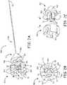
- FIGS. 2A-Bare a perspective view and an end view of a tethering assembly 500, according to some embodiments, for example, that may be part of a delivery catheter 345 in a system described below in conjunction with FIGS. 3A-C .
- FIGS. 2A-Billustrates tethering assembly 500 including a tether line 580, a grip member 540, and a release member 520, wherein tether line 580 has a distal end 584 that is coupled to a base 546 of grip member 540, and tether line 580 extends proximally from distal end 584 through a longitudinal lumen 525 of release member 520, which is better seen in FIG. 2C.
- FIG. 1illustrates tethering assembly 500 including a tether line 580, a grip member 540, and a release member 520, wherein tether line 580 has a distal end 584 that is coupled to a base 546 of grip member 540, and tether line
- grip member 540including a plurality of elastic fingers 544 extending distally from grip member base 546 and being spaced apart from one another around a plurality of apertures 543 that are formed through base 546.
- FIGS. 2A-Beach of a plurality of legs 523 of release member 520 are shown extending from a base 526 of release member 520 and through a corresponding aperture 543 of grip member 540.
- grip member fingers 544define a cavity 504 of grip member 540, which is sized to hold a proximal end of an implantable medical device, for example, as described below in conjunction with FIG. 3B .
- FIG. 2Cis an exploded perspective view of grip member 540 and release member 520.
- FIG. 2Cillustrates grip and release members 540, 520 positioned for assembly together, per arrow A, wherein a distal end 53 of each leg 523 includes a barb-like projection 513 that has a tapered leading edge, to allow passage of each distal end 53 through the corresponding aperture 543 in the distal direction, per arrow A.
- a trailing shoulder of each barb-like projection 513secures release member 520 to grip member 540 by abutting grip member base 546, for example, as shown in FIGS. 2B and 3C .
- each release member leg 523is in sliding engagement within the corresponding grip member aperture 543 to move, per arrow S, from a first position (shown) to a second position within cavity 504.
- first positionshown
- second positionwithin cavity 504.
- grip member 540 and release member 520are each molded from a relatively rigid medical grade plastic, examples of which include, without limitation, nylon, PEEK, ABS, and polyurethane; and tether line 580 is formed from a polyester fiber, which may have a fluoropolymer coating, in some embodiments.
- a knot in tether line distal end 584, or a bead-like member attached to distal end 584,may help to secure tether line 580 to grip member 540.
- FIG. 3Ais a plan view of an interventional medical system that includes an implantable medical device 700 and the aforementioned delivery catheter 345 for deploying device 700, according to some embodiments.
- device 700includes an electronic controller and associated power source (not shown) contained in hermetically sealed housing 105, wherein electrode 111, being mounted to housing 105 at a distal end 702 of device 700, is electrically coupled to the controller, for example, by any suitable type of hermetically sealed feedthrough assembly known to those skilled in the art.
- a portion of the insulation layer overlaying housing 105 of device 700may be removed to form another electrode 112, for example, to provide bipolar pacing and sensing in conjunction with electrode 111.
- FIG. 1is a plan view of an interventional medical system that includes an implantable medical device 700 and the aforementioned delivery catheter 345 for deploying device 700, according to some embodiments.
- device 700includes an electronic controller and associated power source (not shown) contained in hermetically sealed housing 105, wherein electrode 111, being mounted to housing 105
- FIG. 3Aillustrates catheter 345 including tethering assembly 500 and an elongate tubular member 420, which has a lumen 402 ( FIGS. 3C , 4A-B ) within which tether line 580 of assembly 500 extends so that grip and release members 540, 520 of tethering assembly 500 are located distal to a distal end 422 of tubular member 420.
- Tubular member 420may be formed, for example, by extrusion, from any suitable medical grade polymer such as polyether block amide.
- a proximal end (not shown) of tubular member 420is coupled to a handle assembly 310 of catheter 345, and a proximal end 581 of tether line 580 extends proximally out from handle assembly 310.
- FIG. 3Afurther illustrates catheter 345 including an outer shaft 320, which is slideably engaged around tubular member 420 and tethering assembly 500, and is coupled to a control member 311 of handle assembly 310, which is operable to move outer shaft 320 relative to tubular member 420 and tethering assembly 500.
- outer shaft 320 of catheter 345may be constructed in a similar fashion to a deployment tube of a tool described in co-pending and commonly assigned U.S. Patent Application US 2015/0094668 , Serial No. 14/039,937 (Atty. Docket No. C00005393.USU1).
- FIG. 3Ashows outer shaft 320 in a retracted position with grip and release members 540, 520 of tethering assembly 500 exposed for insertion of a proximal end 701 of device 700 into grip member cavity 504 ( FIG. 2A ).
- a proximal end 701 of device 700includes a knob-like member 721, which an operator can insert into grip member cavity 504 by pushing member 721 against inward tapering distal-facing surfaces 54 of grip member fingers 544 ( FIGS. 2A-B ) to elastically deform fingers 544, per arrows f, of FIG. 2A .
- device proximal end 701can be held by grip member fingers 544 within cavity 504 so that proximal-facing surfaces 45 of grip member fingers 544 abut knob-like member 721, as shown in FIGS. 3B-C .
- the cut-away cross-section of FIG. 3Cillustrates the aforementioned first position of tethering assembly release member legs 523, at which knob-like member 721 of device proximal end 701 and distal ends 53 of legs 523 both fit within grip member cavity 504.
- Proximal facing surfaces 45 of grip member fingers 544are oriented to provide a sufficient holding force that keeps device 700 tethered to catheter 345, until the operator takes steps to release/deploy device 700, for example, as described below. (In addition to the orientation of surfaces 45, a thickness of each finger 544 factors into the holding force.)
- Fixation member 115may be cut from Nitinol tubing, according to methods known in the art, and fixation member 115 may be mounted to device housing 105 in a manner similar to that described for a fixation component in co-pending and commonly assigned United States Patent Application 2012/0172690 .
- the super-elastic nature of Nitinolallows the fingers of fixation member 115 to elastically deform between the relaxed and extended conditions.
- FIG. 4Ais a schematic pertaining to methods for deploying an implantable medical device, for example, device 700 from delivery catheter 345, according to some embodiments.
- FIG. 4Aillustrates fixation member 115 of device 700 engaged with tissue at an implant site, for example, within a patient's right ventricle RV ( FIG. 1 ).
- the operatorPrior to retracting outer shaft 320 relative to the tethered device 700 and tubular member 420, to engage fixation member 115, the operator has advanced catheter 345, for example, in the patient's venous system, and maneuvered outer shaft distal-most portion 322 into proximity with the implant site.
- the operatorcan test the fixation of engaged device fixation member 115, by applying a tug force to grip member 540, through tether line 580.
- tether line proximal end 581is shown extending out from a reversible locking member 886 of handle assembly 310.
- locking member 886is unlocked to allow the operator to tug, per arrow T, on tether line proximal end 581.
- locking member 886is in the form of a stopcock-type valve, known to those skilled in the art, which includes a controller 86 for alternately opening and constricting a lumen of locking member 886 through which tether line 580 passes.
- Grip member fingers 544are configured, as described above, to hold device proximal end 701 in grip member cavity 504, until device proximal end 701 is pushed out from grip member cavity 504 by moving release member legs 523 within cavity 504 to the second position (shown in FIG. 4B ).
- release member 520is not impinged upon by any force to move legs 523 relative to grip member 540 when the operator applies the tug force to test the fixation of engaged device fixation member 115.
- FIG. 4Bis a cross-section view through a portion of the system, when the operator, satisfied with the implant of device 700, has taken steps to move release member 520 to the second position, thereby releasing/deploying device 700.
- FIG. 4Billustrates catheter tubular member 420 having been advanced relative to tethering assembly 500, so that tubular member distal end 422 abuts release member base 526. According to the illustrated embodiment, the abutting distal end 422 provides a back-up force for the operator to increase a tension in tether line 580 and pull grip member 540 proximally relative to release member 520, thereby moving release member legs 523 to the second position.
- FIG. 4Bfurther illustrates release member base 526 having a tapered proximal end that can wedge within a distal opening of tubular member lumen 402 when distal end 422 provides the back-up force, according to some embodiments.
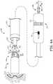
- FIG. 5Ais a cross-section view through a portion of catheter handle assembly 310, according to some embodiments.
- FIG. 5Aillustrates the aforementioned reversible locking member 886 being coupled to an elongate threaded shaft 885, which extends within a shell of handle assembly 310, and has a lumen 805 in fluid communication with the lumen of locking member 886, through which tether line 580 extends.
- FIG. 5Afurther illustrates a thumbwheel type control member 312 of handle assembly 310 engaged with threaded shaft 885 to longitudinally move locking member 886 relative to tubular member 420.
- FIG. 5Bis a schematic representation of a portion of a handle assembly that may be employed by some alternate embodiments of catheter 345.
- Handle assembly embodimentsmay be constructed from injection molded, relatively hard, medical grade plastic parts, according to methods known in the art.
Landscapes
- Health & Medical Sciences (AREA)
- Life Sciences & Earth Sciences (AREA)
- Animal Behavior & Ethology (AREA)
- General Health & Medical Sciences (AREA)
- Nuclear Medicine, Radiotherapy & Molecular Imaging (AREA)
- Engineering & Computer Science (AREA)
- Biomedical Technology (AREA)
- Veterinary Medicine (AREA)
- Public Health (AREA)
- Radiology & Medical Imaging (AREA)
- Heart & Thoracic Surgery (AREA)
- Cardiology (AREA)
- Surgery (AREA)
- Molecular Biology (AREA)
- Medical Informatics (AREA)
- Rheumatology (AREA)
- Vascular Medicine (AREA)
- Pathology (AREA)
- Surgical Instruments (AREA)
- Media Introduction/Drainage Providing Device (AREA)
- Electrotherapy Devices (AREA)
Description
- The present disclosure pertains to interventional medical systems, and more particularly to associated tethering assemblies and methods.
- The traditional implantable cardiac pacemaker includes a pulse generator device to which one or more flexible elongate lead wires are coupled. The device is typically implanted in a subcutaneous pocket, remote from the heart, and each of the one or more lead wires extends therefrom to a corresponding electrode, coupled thereto and positioned at a pacing site, either endocardial or epicardial. Mechanical complications and/or MRI compatibility issues, which are sometimes associated with elongate lead wires and well known to those skilled in the art, have motivated the development of implantable cardiac pacing devices that are wholly contained within a relatively compact package for implant in close proximity to the pacing site, for example, within the right ventricle RV of the heart.
US 2013/053921 A1 relates to holding members for implantable cardiac stimulation devices. - The present disclosure pertains to improved apparatus and methods related to the tethering of implantable medical devices. According to some embodiments, in an interventional medical system, a delivery catheter for deploying a medical device of the system has a tethering assembly that includes a tether line, a grip member, and a release member, wherein the tether line extends through a longitudinal lumen of a base of the release member and is coupled to a base of the grip member, and the release member has legs extending though apertures formed through the base of the grip member. The device may be tethered to the catheter such that a proximal end of the device is held within a cavity of the tethering assembly grip member, which is defined by a plurality of elastic fingers of the grip member that extend distally from the grip member base; and the device may be deployed from the catheter by moving the legs of the tethering assembly release member within the grip member cavity to push the proximal end of the device out from the grip member cavity.
- According to some embodiments and methods, the tethering assembly tether line extends within an elongate tubular member of the delivery catheter, and the tubular member is configured so that a distal end thereof can abut the tethering assembly release member to provide a backup force when increased tension in the tether line pulls the tethering assembly grip member proximally relative to the release member to push the device out from the cavity by moving the legs of the release member within the grip member cavity. A handle assembly of the delivery catheter, which is coupled to the tubular member, may include a locking member for securing the tethering assembly tether line, wherein the locking member may be moveable relative to the tubular member to vary the tension in the tether line, when the tether line is locked therein.
- The following drawings are illustrative of particular embodiments of the present invention and therefore do not limit the scope of the invention. The drawings are not to scale (unless so stated) and are intended for use in conjunction with the explanations in the following detailed description. Embodiments will hereinafter be described in conjunction with the appended drawings wherein like numerals denote like elements, and:
FIG. 1 is a schematic showing an exemplary implant of a relatively compact medical device, via an exemplary delivery catheter;FIG. 2A is a perspective view of a tethering assembly for a delivery catheter, according to some embodiments;FIG. 2B is an end view of the tethering assembly, according to some embodiments;FIG. 2C is an exploded perspective view of a portion of the tethering assembly, according to some embodiments;FIG. 3A is a plan view of an interventional medical system, according to some embodiments;FIG. 3B is a perspective view of a portion of the system, according to some embodiments;FIG. 3C is a plan view of the portion of the system, with a cut-away cross-section through a delivery catheter of the system, according to some embodiments;FIG. 4A is a schematic pertaining to methods for deploying an implantable medical device from the delivery catheter of the system, according to some embodiments;FIG. 4B is a cross-section view through a portion of the system when a release member of a tethering assembly of the delivery catheter has been moved to a second position, according to some embodiments and methods;FIG. 5A is a cross-section view through a portion of a handle assembly of the system delivery catheter, according to some embodiments; andFIG. 5B is a schematic representation of a portion of a handle assembly, which may be employed by some alternate embodiments of the delivery catheter.- The following detailed description is exemplary in nature and is not intended to limit the scope, applicability, or configuration of the invention in any way. Rather, the following description provides practical examples, and those skilled in the art will recognize that some of the examples may have suitable alternatives.
- With reference to
FIG. 1 , adevice 100 includes a hermetically sealedhousing 105, preferably formed from a biocompatible and biostable metal such as titanium, contains an electronic controller and associated power source (not shown), to which at least oneelectrode 111 is coupled, for example, by a hermetic feedthrough assembly (not shown) like those known to those skilled in the art.Housing 105 may be overlaid with an insulative layer, for example, medical grade polyurethane, parylene, or silicone, and a portion of the insulation layer may be removed to formanother electrode 112, for example, which provides bipolar pacing and sensing in conjunction withelectrode 111. FIG. 1 showsdevice 100 having been deployed by an operator out from adistal opening 203 of adelivery catheter 200, which the operator has maneuvered up through the inferior vena cava IVC and across the right atrium RA into the right ventricle RV. The deployeddevice 100 is shown fixed at an implant site by afixation member 115 thereof, but still secured tocatheter 200 by atether 280 that extends out fromdistal opening 203 ofcatheter 200.- Securing
device 100 tocatheter 200 withtether 280 is typically accomplished by loopingtether 280 through anattachment feature 121 ofdevice 100 and threading first andsecond lengths tether 280 through one or more lumens ofcatheter 200 such that opposing ends thereof protrude out from aproximal opening 201 ofcatheter 200. After deployingdevice 100, the operator can grasp the ends oflengths tether 280, for example, to test the fixation ofdevice 100 at the implant site, and/or to apply a greater force to tether 280 to removedevice 100 from the implant site for repositioning at a more suitable site, if necessary. If satisfied with the implant ofdevice 100, the operator can un-tetherdevice 100 fromcatheter 200 by releasing, for example, the end oftether length 281, and then pulling on the end of theother tether length 282, thereby withdrawing an entirety oflength 282 proximally throughdelivery catheter 200 so that theother length 281 is pulled distally and through device tether attachment feature 121, out from engagement therewith. FIGS. 2A-B are a perspective view and an end view of atethering assembly 500, according to some embodiments, for example, that may be part of adelivery catheter 345 in a system described below in conjunction withFIGS. 3A-C .FIGS. 2A-B illustratestethering assembly 500 including atether line 580, agrip member 540, and arelease member 520, whereintether line 580 has adistal end 584 that is coupled to abase 546 ofgrip member 540, andtether line 580 extends proximally fromdistal end 584 through alongitudinal lumen 525 ofrelease member 520, which is better seen inFIG. 2C. FIG. 2A further illustratesgrip member 540 including a plurality ofelastic fingers 544 extending distally fromgrip member base 546 and being spaced apart from one another around a plurality ofapertures 543 that are formed throughbase 546. InFIGS. 2A-B , each of a plurality oflegs 523 ofrelease member 520 are shown extending from abase 526 ofrelease member 520 and through acorresponding aperture 543 ofgrip member 540. According to the illustrated embodiment,grip member fingers 544 define acavity 504 ofgrip member 540, which is sized to hold a proximal end of an implantable medical device, for example, as described below in conjunction withFIG. 3B .FIG. 2C is an exploded perspective view ofgrip member 540 and releasemember 520.FIG. 2C illustrates grip and releasemembers distal end 53 of eachleg 523 includes a barb-like projection 513 that has a tapered leading edge, to allow passage of eachdistal end 53 through thecorresponding aperture 543 in the distal direction, per arrow A. According to the illustrated embodiment, oncedistal end 53 of eachrelease member leg 523 passes through the correspondinggrip member aperture 543, a trailing shoulder of each barb-like projection 513 securesrelease member 520 togrip member 540 by abuttinggrip member base 546, for example, as shown inFIGS. 2B and3C . According to the illustrated embodiment, eachrelease member leg 523 is in sliding engagement within the correspondinggrip member aperture 543 to move, per arrow S, from a first position (shown) to a second position withincavity 504. Whenrelease member legs 523 are in the first position, the aforementioned proximal end of the medical device anddistal ends 53 oflegs 523 fit withingrip member cavity 504.- According to an exemplary embodiment,
grip member 540 andrelease member 520 are each molded from a relatively rigid medical grade plastic, examples of which include, without limitation, nylon, PEEK, ABS, and polyurethane; andtether line 580 is formed from a polyester fiber, which may have a fluoropolymer coating, in some embodiments. A knot in tether linedistal end 584, or a bead-like member attached todistal end 584, may help to securetether line 580 togrip member 540. FIG. 3A is a plan view of an interventional medical system that includes an implantablemedical device 700 and theaforementioned delivery catheter 345 for deployingdevice 700, according to some embodiments. Likedevice 100, described above in conjunction withFIG. 1 ,device 700 includes an electronic controller and associated power source (not shown) contained in hermetically sealedhousing 105, whereinelectrode 111, being mounted tohousing 105 at adistal end 702 ofdevice 700, is electrically coupled to the controller, for example, by any suitable type of hermetically sealed feedthrough assembly known to those skilled in the art. Also likedevice 100, a portion of the insulationlayer overlaying housing 105 ofdevice 700 may be removed to form anotherelectrode 112, for example, to provide bipolar pacing and sensing in conjunction withelectrode 111.FIG. 3A illustratescatheter 345 includingtethering assembly 500 and an elongatetubular member 420, which has a lumen 402 (FIGS. 3C ,4A-B ) within whichtether line 580 ofassembly 500 extends so that grip andrelease members tethering assembly 500 are located distal to adistal end 422 oftubular member 420.Tubular member 420 may be formed, for example, by extrusion, from any suitable medical grade polymer such as polyether block amide. According to the illustrated embodiment, a proximal end (not shown) oftubular member 420 is coupled to ahandle assembly 310 ofcatheter 345, and aproximal end 581 oftether line 580 extends proximally out fromhandle assembly 310.FIG. 3A further illustratescatheter 345 including anouter shaft 320, which is slideably engaged aroundtubular member 420 andtethering assembly 500, and is coupled to acontrol member 311 ofhandle assembly 310, which is operable to moveouter shaft 320 relative totubular member 420 andtethering assembly 500. According to an exemplary embodiment,outer shaft 320 ofcatheter 345 may be constructed in a similar fashion to a deployment tube of a tool described in co-pending and commonly assigned U.S. Patent ApplicationUS 2015/0094668 , Serial No.14/039,937 FIG. 3A showsouter shaft 320 in a retracted position with grip andrelease members tethering assembly 500 exposed for insertion of aproximal end 701 ofdevice 700 into grip member cavity 504 (FIG. 2A ). According to the illustrated embodiment, aproximal end 701 ofdevice 700 includes a knob-like member 721, which an operator can insert intogrip member cavity 504 by pushingmember 721 against inward tapering distal-facingsurfaces 54 of grip member fingers 544 (FIGS. 2A-B ) to elastically deformfingers 544, per arrows f, ofFIG. 2A . Thus, deviceproximal end 701 can be held bygrip member fingers 544 withincavity 504 so that proximal-facingsurfaces 45 ofgrip member fingers 544 abut knob-like member 721, as shown inFIGS. 3B-C . The cut-away cross-section ofFIG. 3C illustrates the aforementioned first position of tethering assemblyrelease member legs 523, at which knob-like member 721 of deviceproximal end 701 anddistal ends 53 oflegs 523 both fit withingrip member cavity 504. Proximal facing surfaces 45 ofgrip member fingers 544 are oriented to provide a sufficient holding force that keepsdevice 700 tethered tocatheter 345, until the operator takes steps to release/deploydevice 700, for example, as described below. (In addition to the orientation ofsurfaces 45, a thickness of eachfinger 544 factors into the holding force.)- With further reference to
FIG. 3B , when deviceproximal end 701 is held bygrip member fingers 544, the operator can complete the loading ofdevice 700 intocatheter 345 by movingouter shaft 320, per arrow C, for example, via control member 311 (FIG. 3A ), so that adistal-most portion 322 ofshaft 320 containsdevice 700, for example, as shown inFIG. 3C . According to the illustrated embodiment, when the operator advancesouter shaft 320 over device 700 a plurality of elastic fixation fingers offixation member 115 are moved from a relaxed condition (FIG. 3A ) to an extended condition (FIG. 3C ).Fixation member 115 may be cut from Nitinol tubing, according to methods known in the art, andfixation member 115 may be mounted todevice housing 105 in a manner similar to that described for a fixation component in co-pending and commonly assigned United States Patent Application2012/0172690 . The super-elastic nature of Nitinol allows the fingers offixation member 115 to elastically deform between the relaxed and extended conditions. FIG. 4A is a schematic pertaining to methods for deploying an implantable medical device, for example,device 700 fromdelivery catheter 345, according to some embodiments.FIG. 4A illustratesfixation member 115 ofdevice 700 engaged with tissue at an implant site, for example, within a patient's right ventricle RV (FIG. 1 ). Prior to retractingouter shaft 320 relative to thetethered device 700 andtubular member 420, to engagefixation member 115, the operator has advancedcatheter 345, for example, in the patient's venous system, and maneuvered outer shaftdistal-most portion 322 into proximity with the implant site. According to some methods, the operator can test the fixation of engageddevice fixation member 115, by applying a tug force togrip member 540, throughtether line 580. InFIG. 4A , tether lineproximal end 581 is shown extending out from areversible locking member 886 ofhandle assembly 310. InFIG. 4A locking member 886 is unlocked to allow the operator to tug, per arrow T, on tether lineproximal end 581. According to an exemplary embodiment, lockingmember 886 is in the form of a stopcock-type valve, known to those skilled in the art, which includes acontroller 86 for alternately opening and constricting a lumen of lockingmember 886 through whichtether line 580 passes.Grip member fingers 544 are configured, as described above, to hold deviceproximal end 701 ingrip member cavity 504, until deviceproximal end 701 is pushed out fromgrip member cavity 504 by movingrelease member legs 523 withincavity 504 to the second position (shown inFIG. 4B ). InFIG. 4A ,release member 520 is not impinged upon by any force to movelegs 523 relative togrip member 540 when the operator applies the tug force to test the fixation of engageddevice fixation member 115.FIG. 4B is a cross-section view through a portion of the system, when the operator, satisfied with the implant ofdevice 700, has taken steps to moverelease member 520 to the second position, thereby releasing/deployingdevice 700.FIG. 4B illustratescatheter tubular member 420 having been advanced relative totethering assembly 500, so that tubular memberdistal end 422 abutsrelease member base 526. According to the illustrated embodiment, the abuttingdistal end 422 provides a back-up force for the operator to increase a tension intether line 580 and pullgrip member 540 proximally relative to releasemember 520, thereby movingrelease member legs 523 to the second position.FIG. 4B further illustratesrelease member base 526 having a tapered proximal end that can wedge within a distal opening oftubular member lumen 402 whendistal end 422 provides the back-up force, according to some embodiments.FIG. 5A is a cross-section view through a portion ofcatheter handle assembly 310, according to some embodiments.FIG. 5A illustrates the aforementioned reversible lockingmember 886 being coupled to an elongate threadedshaft 885, which extends within a shell ofhandle assembly 310, and has a lumen 805 in fluid communication with the lumen of lockingmember 886, through whichtether line 580 extends.FIG. 5A further illustrates a thumbwheeltype control member 312 ofhandle assembly 310 engaged with threadedshaft 885 to longitudinallymove locking member 886 relative totubular member 420. According to the illustrated embodiment, whentether line 580 is locked in lockingmember 886, for example, by rotatingcontroller 86 of lockingmember 886, per arrow Y, and tubular memberdistal end 422 abuts release member base 526 (FIG. 4B ), the operator can increase the tension intether line 580 in a relatively steady and controlled fashion by rotatingcontrol member 312, per arrow R, to move lockingmember 886 proximally, per arrow P, and thereby release/deploydevice 700 as described above.FIG. 5B is a schematic representation of a portion of a handle assembly that may be employed by some alternate embodiments ofcatheter 345.FIG. 5B illustrates the handle assembly including acam action lever 912 engaged with lockingmember 886 to longitudinallymove locking member 886, relative totubular member 420, per arrow P, whenlever 912 is lifted, per arrow L. Handle assembly embodiments may be constructed from injection molded, relatively hard, medical grade plastic parts, according to methods known in the art.- In the foregoing detailed description, the invention has been described with reference to specific embodiments. However, it may be appreciated that various modifications and changes can be made without departing from the scope of the invention as set forth in the appended claims.
Claims (10)
- A delivery catheter for deploying an implantable medical device at an implant site, and the delivery catheter (345) comprising:an elongate tubular member (420) extending from a proximal end to a distal end (422), the elongate tubular member including a lumen (402) that extends from a proximal opening at the proximal end to a distal opening at the distal end; anda tethering assembly (500) comprising:a tether line (580);a grip member (540) located distal to the distal end of the elongate tubular member and configured to be coupled to the tether line, the grip member comprising a grip member base (546), a plurality of apertures (543) formed through the grip member base, and a plurality of elastic fingers (544) extending distally from the grip member base and being spaced apart from one another around the plurality of apertures, the plurality of elastic fingers defining a cavity (504) and being configured to hold a proximal end of the implantable medical device within the cavity, and each elastic finger of the plurality of elastic fingers being deformable to allow insertion and withdrawal of the proximal end of the implantable medical device;a release member (520) comprising a release member base, a longitudinal lumen extending through the release member base (526) and configured to allow the tether line to pass through the release member, and a plurality of legs (523) extending distally from the release member base, each leg of the plurality of legs extending through and being in sliding engagement with a corresponding aperture of the plurality of apertures of the grip member base and having a distal end configured to secure the release member to the grip member, the release member being movable from a first position in which the proximal end of the implantable medical device fits within the cavity of the grip member and a second position in which the plurality of legs extend into the cavity of the grip member such that the proximal end of the implantable medical device does not fit therein.
- The delivery catheter of claim 1, wherein the elongate tubular member is configured to abut the release member base to provide a backup force when the tension is increased in the tether line.
- The delivery catheter of claim 2, wherein the release member base includes a tapered proximal end sized to wedge within the distal opening of the tubular member.
- The delivery catheter of any of claims 1-3, wherein the distal end of each release member leg of the plurality of legs comprises a barb-like projection (513).
- The delivery catheter of any of claims 1-4, wherein the delivery catheter further comprises a handle assembly (310) coupled to the proximal end of the tubular member, the handle assembly including a reversible locking member (886) through which a proximal end of the tether line extends, the locking member being longitudinally moveable relative to the tubular member to vary the tension on the tether line when the proximal end of the tether line is locked in the locking member and the distal end of the tubular member abuts the release member base.
- The delivery catheter of claim 5, wherein the handle assembly further includes an elongate threaded shaft (885) coupled to the locking member, the shaft having a lumen (805) through which the tether line extends in proximity to the locking member, and a thumbwheel type control member (312) engaged with the threaded shaft to longitudinally move the locking member relative to the tubular member.
- The delivery catheter of claim 5, wherein the handle assembly further includes a cam action lever (912) engaged with the locking member to longitudinally move the locking member relative to the tubular member.
- The delivery catheter of claim 1, further comprising an outer shaft (320) slideably engaged around the tubular member, the outer shaft including a distal-most portion (322) sized to contain the implantable medical device therein when the proximal end of the implantable medical device is held in the cavity by the grip member fingers.
- The delivery catheter of claim 1, wherein the implantable medical device comprises an electronic controller and an associated power source, a hermetically sealed housing (105) containing the controller and power source, an electrode (111) electrically coupled to the controller and mounted to the housing, and a fixation member (115) mounted to a distal end of the housing.
- The delivery catheter of claim 9, wherein the proximal end of the implantable medical device comprises a knob-like member (721) coupled to a proximal end of the housing thereof.
Applications Claiming Priority (2)
| Application Number | Priority Date | Filing Date | Title |
|---|---|---|---|
| US15/223,585US10238864B2 (en) | 2016-07-29 | 2016-07-29 | Interventional medical systems and associated tethering assemblies and methods |
| PCT/US2017/044305WO2018022961A1 (en) | 2016-07-29 | 2017-07-28 | Interventional medical systems and associated tethering assemblies and methods |
Publications (2)
| Publication Number | Publication Date |
|---|---|
| EP3490666A1 EP3490666A1 (en) | 2019-06-05 |
| EP3490666B1true EP3490666B1 (en) | 2020-02-12 |
Family
ID=59582024
Family Applications (1)
| Application Number | Title | Priority Date | Filing Date |
|---|---|---|---|
| EP17751530.1AActiveEP3490666B1 (en) | 2016-07-29 | 2017-07-28 | Interventional medical systems and associated tethering assemblies |
Country Status (4)
| Country | Link |
|---|---|
| US (1) | US10238864B2 (en) |
| EP (1) | EP3490666B1 (en) |
| CN (1) | CN109475744B (en) |
| WO (1) | WO2018022961A1 (en) |
Families Citing this family (22)
| Publication number | Priority date | Publication date | Assignee | Title |
|---|---|---|---|---|
| US10575872B2 (en) | 2016-10-14 | 2020-03-03 | Pacesetter, Inc. | Catheter-based system for delivery and retrieval of a leadless pacemaker |
| US11376039B2 (en) | 2017-03-30 | 2022-07-05 | Medtronic, Inc. | Interventional medical systems and associated assemblies |
| WO2018236958A1 (en)* | 2017-06-22 | 2018-12-27 | St. Jude Medical, Cardiology Division, Inc. | ADMINISTRATION DEVICE WITH ATTACHMENT FOR IMPLANTABLE MEDICAL DEVICE |
| CN112020376B (en) | 2018-03-09 | 2024-06-25 | 先导者股份有限公司 | Leadless pacemaker with attachment features |
| US10874850B2 (en) | 2018-09-28 | 2020-12-29 | Medtronic, Inc. | Impedance-based verification for delivery of implantable medical devices |
| FR3087344B1 (en)* | 2018-10-17 | 2021-04-23 | Cairdac | COUPLING SYSTEM BETWEEN AN AUTONOMOUS HEART CAPSULE AND ITS IMPLEMENTATION TOOL |
| USD894396S1 (en) | 2019-03-08 | 2020-08-25 | Pacesetter, Inc. | Leadless biostimulator attachment feature |
| EP3946556B1 (en) | 2019-03-29 | 2024-06-19 | Cardiac Pacemakers, Inc. | Systems for treating cardiac arrhythmias |
| CN113660977B (en) | 2019-03-29 | 2024-12-17 | 心脏起搏器股份公司 | Systems and methods for treating cardiac arrhythmias |
| US11331475B2 (en)* | 2019-05-07 | 2022-05-17 | Medtronic, Inc. | Tether assemblies for medical device delivery systems |
| US12151100B2 (en)* | 2019-05-07 | 2024-11-26 | Medtronic, Inc. | Tether assemblies for medical device delivery systems |
| US11938279B2 (en)* | 2019-08-15 | 2024-03-26 | Medtronic, Inc. | Valve clamp for device delivery catheter handle |
| WO2021050685A1 (en) | 2019-09-11 | 2021-03-18 | Cardiac Pacemakers, Inc. | Tools and systems for implanting and/or retrieving a leadless cardiac pacing device with helix fixation |
| US11510697B2 (en) | 2019-09-11 | 2022-11-29 | Cardiac Pacemakers, Inc. | Tools and systems for implanting and/or retrieving a leadless cardiac pacing device with helix fixation |
| CN114641264B (en)* | 2019-10-31 | 2025-07-15 | 杭州启明医疗器械股份有限公司 | Interventional device delivery system that is easy to operate with one hand |
| CN111012549B (en)* | 2019-12-27 | 2022-05-20 | 先健科技(深圳)有限公司 | Force measuring device |
| EP4438098A3 (en)* | 2020-06-10 | 2024-12-18 | Edwards Lifesciences Corporation | Release mechanism for a delivery apparatus for an implantable medical device |
| KR102501306B1 (en)* | 2020-09-16 | 2023-02-21 | 전남대학교 산학협력단 | Multi leadless pacemaker and surgical device |
| US20220339014A1 (en)* | 2021-04-23 | 2022-10-27 | DeepIn Technologies, LLC | Mechanical detachment system with a hold-release structure for deployment of endovascular devices |
| US12329411B2 (en)* | 2021-07-14 | 2025-06-17 | Medtronic, Inc. | Tether assemblies for medical device retrieval systems |
| WO2024236438A1 (en)* | 2023-05-17 | 2024-11-21 | Medtronic, Inc. | Retainer for a medical device delivery system |
| WO2025093977A1 (en)* | 2023-10-31 | 2025-05-08 | Medtronic, Inc. | Tether assemblies for medical device delivery systems |
Family Cites Families (26)
| Publication number | Priority date | Publication date | Assignee | Title |
|---|---|---|---|---|
| US5350397A (en) | 1992-11-13 | 1994-09-27 | Target Therapeutics, Inc. | Axially detachable embolic coil assembly |
| US6277125B1 (en) | 1998-10-05 | 2001-08-21 | Cordis Neurovascular, Inc. | Embolic coil deployment system with retaining jaws |
| CA2643221A1 (en) | 2002-03-15 | 2003-09-25 | Nmt Medical, Inc. | Coupling system useful in placement of implants |
| US7473266B2 (en) | 2003-03-14 | 2009-01-06 | Nmt Medical, Inc. | Collet-based delivery system |
| US20050267555A1 (en) | 2004-05-28 | 2005-12-01 | Marnfeldt Goran N | Engagement tool for implantable medical devices |
| US7650186B2 (en) | 2004-10-20 | 2010-01-19 | Boston Scientific Scimed, Inc. | Leadless cardiac stimulation systems |
| US8676349B2 (en) | 2006-09-15 | 2014-03-18 | Cardiac Pacemakers, Inc. | Mechanism for releasably engaging an implantable medical device for implantation |
| CA2713341C (en)* | 2008-02-05 | 2016-09-27 | Cvdevices, Llc | Steering engagement catheter devices, systems, and methods |
| JP5153892B2 (en)* | 2008-02-07 | 2013-02-27 | カーディアック ペースメイカーズ, インコーポレイテッド | Wireless tissue electrical stimulation |
| US8231271B2 (en) | 2009-04-09 | 2012-07-31 | Welch Allyn, Inc. | IR thermometry probe cover |
| US8777932B2 (en) | 2010-04-29 | 2014-07-15 | Medtronic, Inc. | Catheter connectors and systems, and methods of using same |
| US8615310B2 (en) | 2010-12-13 | 2013-12-24 | Pacesetter, Inc. | Delivery catheter systems and methods |
| US9775982B2 (en) | 2010-12-29 | 2017-10-03 | Medtronic, Inc. | Implantable medical device fixation |
| US10112045B2 (en) | 2010-12-29 | 2018-10-30 | Medtronic, Inc. | Implantable medical device fixation |
| US8758365B2 (en)* | 2011-08-03 | 2014-06-24 | Medtronic, Inc. | Implant system including guiding accessory and methods of use |
| US8504156B2 (en) | 2011-08-26 | 2013-08-06 | Medtronic, Inc. | Holding members for implantable cardiac stimulation devices |
| US8945146B2 (en)* | 2011-10-24 | 2015-02-03 | Medtronic, Inc. | Delivery system assemblies and associated methods for implantable medical devices |
| US9339197B2 (en) | 2012-03-26 | 2016-05-17 | Medtronic, Inc. | Intravascular implantable medical device introduction |
| US9717421B2 (en) | 2012-03-26 | 2017-08-01 | Medtronic, Inc. | Implantable medical device delivery catheter with tether |
| US9220906B2 (en)* | 2012-03-26 | 2015-12-29 | Medtronic, Inc. | Tethered implantable medical device deployment |
| US9480850B2 (en) | 2013-08-16 | 2016-11-01 | Cardiac Pacemakers, Inc. | Leadless cardiac pacemaker and retrieval device |
| US9492674B2 (en) | 2013-08-16 | 2016-11-15 | Cardiac Pacemakers, Inc. | Leadless cardiac pacemaker with delivery and/or retrieval features |
| JP6182675B2 (en) | 2013-08-16 | 2017-08-16 | カーディアック ペースメイカーズ, インコーポレイテッド | Leadless cardiac pacemaker and collection device |
| US9526522B2 (en) | 2013-09-27 | 2016-12-27 | Medtronic, Inc. | Interventional medical systems, tools, and assemblies |
| US9539423B2 (en) | 2014-07-17 | 2017-01-10 | Medtronic, Inc. | Interventional medical systems, tools, and methods of use |
| US10478620B2 (en)* | 2014-08-26 | 2019-11-19 | Medtronic, Inc. | Interventional medical systems, devices, and methods of use |
- 2016
- 2016-07-29USUS15/223,585patent/US10238864B2/enactiveActive
- 2017
- 2017-07-28EPEP17751530.1Apatent/EP3490666B1/enactiveActive
- 2017-07-28CNCN201780044478.6Apatent/CN109475744B/enactiveActive
- 2017-07-28WOPCT/US2017/044305patent/WO2018022961A1/ennot_activeCeased
Non-Patent Citations (1)
| Title |
|---|
| None* |
Also Published As
| Publication number | Publication date |
|---|---|
| US20180028805A1 (en) | 2018-02-01 |
| WO2018022961A1 (en) | 2018-02-01 |
| EP3490666A1 (en) | 2019-06-05 |
| CN109475744A (en) | 2019-03-15 |
| US10238864B2 (en) | 2019-03-26 |
| CN109475744B (en) | 2023-05-26 |
Similar Documents
| Publication | Publication Date | Title |
|---|---|---|
| EP3490666B1 (en) | Interventional medical systems and associated tethering assemblies | |
| EP3285865B1 (en) | Interventional medical systems and associated tethering assemblies and methods | |
| US10052127B2 (en) | Catheters for deploying implantable medical devices, and associated tethering assemblies and methods | |
| US12172004B2 (en) | Compact implantable medical device and delivery device | |
| EP3405252B1 (en) | Interventional medical systems | |
| EP3474946B1 (en) | Delivery systems for implantable medical devices, and associated tethering assemblies | |
| US11207530B2 (en) | Relatively compact implantable medical devices and associated methods for loading the devices into a delivery catheter | |
| US9468773B1 (en) | Interventional medical systems and implantable medical devices including tethering features, and associated methods | |
| US20150273212A1 (en) | Interventional medical systems, tools, and associated methods | |
| US20090198251A1 (en) | Lead delivery, fixation and extraction devices and methods for use with intravascular implantable medical devices |
Legal Events
| Date | Code | Title | Description |
|---|---|---|---|
| STAA | Information on the status of an ep patent application or granted ep patent | Free format text:STATUS: UNKNOWN | |
| STAA | Information on the status of an ep patent application or granted ep patent | Free format text:STATUS: THE INTERNATIONAL PUBLICATION HAS BEEN MADE | |
| PUAI | Public reference made under article 153(3) epc to a published international application that has entered the european phase | Free format text:ORIGINAL CODE: 0009012 | |
| STAA | Information on the status of an ep patent application or granted ep patent | Free format text:STATUS: REQUEST FOR EXAMINATION WAS MADE | |
| 17P | Request for examination filed | Effective date:20190221 | |
| AK | Designated contracting states | Kind code of ref document:A1 Designated state(s):AL AT BE BG CH CY CZ DE DK EE ES FI FR GB GR HR HU IE IS IT LI LT LU LV MC MK MT NL NO PL PT RO RS SE SI SK SM TR | |
| AX | Request for extension of the european patent | Extension state:BA ME | |
| DAV | Request for validation of the european patent (deleted) | ||
| DAX | Request for extension of the european patent (deleted) | ||
| GRAP | Despatch of communication of intention to grant a patent | Free format text:ORIGINAL CODE: EPIDOSNIGR1 | |
| STAA | Information on the status of an ep patent application or granted ep patent | Free format text:STATUS: GRANT OF PATENT IS INTENDED | |
| RIC1 | Information provided on ipc code assigned before grant | Ipc:A61N 1/375 20060101AFI20191030BHEP Ipc:A61N 1/372 20060101ALI20191030BHEP Ipc:A61B 17/34 20060101ALI20191030BHEP | |
| INTG | Intention to grant announced | Effective date:20191125 | |
| RIN1 | Information on inventor provided before grant (corrected) | Inventor name:GRUBAC, VLADIMIR Inventor name:ANDERSON, THOMAS A. | |
| GRAS | Grant fee paid | Free format text:ORIGINAL CODE: EPIDOSNIGR3 | |
| GRAA | (expected) grant | Free format text:ORIGINAL CODE: 0009210 | |
| STAA | Information on the status of an ep patent application or granted ep patent | Free format text:STATUS: THE PATENT HAS BEEN GRANTED | |
| AK | Designated contracting states | Kind code of ref document:B1 Designated state(s):AL AT BE BG CH CY CZ DE DK EE ES FI FR GB GR HR HU IE IS IT LI LT LU LV MC MK MT NL NO PL PT RO RS SE SI SK SM TR | |
| REG | Reference to a national code | Ref country code:GB Ref legal event code:FG4D | |
| REG | Reference to a national code | Ref country code:CH Ref legal event code:EP | |
| REG | Reference to a national code | Ref country code:AT Ref legal event code:REF Ref document number:1231297 Country of ref document:AT Kind code of ref document:T Effective date:20200215 | |
| REG | Reference to a national code | Ref country code:IE Ref legal event code:FG4D | |
| REG | Reference to a national code | Ref country code:DE Ref legal event code:R096 Ref document number:602017011745 Country of ref document:DE | |
| PG25 | Lapsed in a contracting state [announced via postgrant information from national office to epo] | Ref country code:RS Free format text:LAPSE BECAUSE OF FAILURE TO SUBMIT A TRANSLATION OF THE DESCRIPTION OR TO PAY THE FEE WITHIN THE PRESCRIBED TIME-LIMIT Effective date:20200212 Ref country code:NO Free format text:LAPSE BECAUSE OF FAILURE TO SUBMIT A TRANSLATION OF THE DESCRIPTION OR TO PAY THE FEE WITHIN THE PRESCRIBED TIME-LIMIT Effective date:20200512 Ref country code:FI Free format text:LAPSE BECAUSE OF FAILURE TO SUBMIT A TRANSLATION OF THE DESCRIPTION OR TO PAY THE FEE WITHIN THE PRESCRIBED TIME-LIMIT Effective date:20200212 | |
| REG | Reference to a national code | Ref country code:LT Ref legal event code:MG4D | |
| REG | Reference to a national code | Ref country code:NL Ref legal event code:MP Effective date:20200212 | |
| PG25 | Lapsed in a contracting state [announced via postgrant information from national office to epo] | Ref country code:HR Free format text:LAPSE BECAUSE OF FAILURE TO SUBMIT A TRANSLATION OF THE DESCRIPTION OR TO PAY THE FEE WITHIN THE PRESCRIBED TIME-LIMIT Effective date:20200212 Ref country code:IS Free format text:LAPSE BECAUSE OF FAILURE TO SUBMIT A TRANSLATION OF THE DESCRIPTION OR TO PAY THE FEE WITHIN THE PRESCRIBED TIME-LIMIT Effective date:20200612 Ref country code:SE Free format text:LAPSE BECAUSE OF FAILURE TO SUBMIT A TRANSLATION OF THE DESCRIPTION OR TO PAY THE FEE WITHIN THE PRESCRIBED TIME-LIMIT Effective date:20200212 Ref country code:LV Free format text:LAPSE BECAUSE OF FAILURE TO SUBMIT A TRANSLATION OF THE DESCRIPTION OR TO PAY THE FEE WITHIN THE PRESCRIBED TIME-LIMIT Effective date:20200212 Ref country code:GR Free format text:LAPSE BECAUSE OF FAILURE TO SUBMIT A TRANSLATION OF THE DESCRIPTION OR TO PAY THE FEE WITHIN THE PRESCRIBED TIME-LIMIT Effective date:20200513 Ref country code:BG Free format text:LAPSE BECAUSE OF FAILURE TO SUBMIT A TRANSLATION OF THE DESCRIPTION OR TO PAY THE FEE WITHIN THE PRESCRIBED TIME-LIMIT Effective date:20200512 | |
| PG25 | Lapsed in a contracting state [announced via postgrant information from national office to epo] | Ref country code:NL Free format text:LAPSE BECAUSE OF FAILURE TO SUBMIT A TRANSLATION OF THE DESCRIPTION OR TO PAY THE FEE WITHIN THE PRESCRIBED TIME-LIMIT Effective date:20200212 | |
| PG25 | Lapsed in a contracting state [announced via postgrant information from national office to epo] | Ref country code:SM Free format text:LAPSE BECAUSE OF FAILURE TO SUBMIT A TRANSLATION OF THE DESCRIPTION OR TO PAY THE FEE WITHIN THE PRESCRIBED TIME-LIMIT Effective date:20200212 Ref country code:EE Free format text:LAPSE BECAUSE OF FAILURE TO SUBMIT A TRANSLATION OF THE DESCRIPTION OR TO PAY THE FEE WITHIN THE PRESCRIBED TIME-LIMIT Effective date:20200212 Ref country code:SK Free format text:LAPSE BECAUSE OF FAILURE TO SUBMIT A TRANSLATION OF THE DESCRIPTION OR TO PAY THE FEE WITHIN THE PRESCRIBED TIME-LIMIT Effective date:20200212 Ref country code:RO Free format text:LAPSE BECAUSE OF FAILURE TO SUBMIT A TRANSLATION OF THE DESCRIPTION OR TO PAY THE FEE WITHIN THE PRESCRIBED TIME-LIMIT Effective date:20200212 Ref country code:CZ Free format text:LAPSE BECAUSE OF FAILURE TO SUBMIT A TRANSLATION OF THE DESCRIPTION OR TO PAY THE FEE WITHIN THE PRESCRIBED TIME-LIMIT Effective date:20200212 Ref country code:LT Free format text:LAPSE BECAUSE OF FAILURE TO SUBMIT A TRANSLATION OF THE DESCRIPTION OR TO PAY THE FEE WITHIN THE PRESCRIBED TIME-LIMIT Effective date:20200212 Ref country code:ES Free format text:LAPSE BECAUSE OF FAILURE TO SUBMIT A TRANSLATION OF THE DESCRIPTION OR TO PAY THE FEE WITHIN THE PRESCRIBED TIME-LIMIT Effective date:20200212 Ref country code:PT Free format text:LAPSE BECAUSE OF FAILURE TO SUBMIT A TRANSLATION OF THE DESCRIPTION OR TO PAY THE FEE WITHIN THE PRESCRIBED TIME-LIMIT Effective date:20200705 Ref country code:DK Free format text:LAPSE BECAUSE OF FAILURE TO SUBMIT A TRANSLATION OF THE DESCRIPTION OR TO PAY THE FEE WITHIN THE PRESCRIBED TIME-LIMIT Effective date:20200212 | |
| REG | Reference to a national code | Ref country code:DE Ref legal event code:R097 Ref document number:602017011745 Country of ref document:DE | |
| REG | Reference to a national code | Ref country code:AT Ref legal event code:MK05 Ref document number:1231297 Country of ref document:AT Kind code of ref document:T Effective date:20200212 | |
| PLBE | No opposition filed within time limit | Free format text:ORIGINAL CODE: 0009261 | |
| STAA | Information on the status of an ep patent application or granted ep patent | Free format text:STATUS: NO OPPOSITION FILED WITHIN TIME LIMIT | |
| 26N | No opposition filed | Effective date:20201113 | |
| PG25 | Lapsed in a contracting state [announced via postgrant information from national office to epo] | Ref country code:AT Free format text:LAPSE BECAUSE OF FAILURE TO SUBMIT A TRANSLATION OF THE DESCRIPTION OR TO PAY THE FEE WITHIN THE PRESCRIBED TIME-LIMIT Effective date:20200212 Ref country code:IT Free format text:LAPSE BECAUSE OF FAILURE TO SUBMIT A TRANSLATION OF THE DESCRIPTION OR TO PAY THE FEE WITHIN THE PRESCRIBED TIME-LIMIT Effective date:20200212 | |
| PG25 | Lapsed in a contracting state [announced via postgrant information from national office to epo] | Ref country code:PL Free format text:LAPSE BECAUSE OF FAILURE TO SUBMIT A TRANSLATION OF THE DESCRIPTION OR TO PAY THE FEE WITHIN THE PRESCRIBED TIME-LIMIT Effective date:20200212 Ref country code:MC Free format text:LAPSE BECAUSE OF FAILURE TO SUBMIT A TRANSLATION OF THE DESCRIPTION OR TO PAY THE FEE WITHIN THE PRESCRIBED TIME-LIMIT Effective date:20200212 | |
| REG | Reference to a national code | Ref country code:CH Ref legal event code:PL | |
| REG | Reference to a national code | Ref country code:BE Ref legal event code:MM Effective date:20200731 | |
| PG25 | Lapsed in a contracting state [announced via postgrant information from national office to epo] | Ref country code:CH Free format text:LAPSE BECAUSE OF NON-PAYMENT OF DUE FEES Effective date:20200731 Ref country code:LI Free format text:LAPSE BECAUSE OF NON-PAYMENT OF DUE FEES Effective date:20200731 Ref country code:LU Free format text:LAPSE BECAUSE OF NON-PAYMENT OF DUE FEES Effective date:20200728 | |
| PG25 | Lapsed in a contracting state [announced via postgrant information from national office to epo] | Ref country code:BE Free format text:LAPSE BECAUSE OF NON-PAYMENT OF DUE FEES Effective date:20200731 | |
| PG25 | Lapsed in a contracting state [announced via postgrant information from national office to epo] | Ref country code:IE Free format text:LAPSE BECAUSE OF NON-PAYMENT OF DUE FEES Effective date:20200728 | |
| GBPC | Gb: european patent ceased through non-payment of renewal fee | Effective date:20210728 | |
| PG25 | Lapsed in a contracting state [announced via postgrant information from national office to epo] | Ref country code:GB Free format text:LAPSE BECAUSE OF NON-PAYMENT OF DUE FEES Effective date:20210728 | |
| PG25 | Lapsed in a contracting state [announced via postgrant information from national office to epo] | Ref country code:TR Free format text:LAPSE BECAUSE OF FAILURE TO SUBMIT A TRANSLATION OF THE DESCRIPTION OR TO PAY THE FEE WITHIN THE PRESCRIBED TIME-LIMIT Effective date:20200212 Ref country code:MT Free format text:LAPSE BECAUSE OF FAILURE TO SUBMIT A TRANSLATION OF THE DESCRIPTION OR TO PAY THE FEE WITHIN THE PRESCRIBED TIME-LIMIT Effective date:20200212 Ref country code:CY Free format text:LAPSE BECAUSE OF FAILURE TO SUBMIT A TRANSLATION OF THE DESCRIPTION OR TO PAY THE FEE WITHIN THE PRESCRIBED TIME-LIMIT Effective date:20200212 | |
| PG25 | Lapsed in a contracting state [announced via postgrant information from national office to epo] | Ref country code:MK Free format text:LAPSE BECAUSE OF FAILURE TO SUBMIT A TRANSLATION OF THE DESCRIPTION OR TO PAY THE FEE WITHIN THE PRESCRIBED TIME-LIMIT Effective date:20200212 Ref country code:AL Free format text:LAPSE BECAUSE OF FAILURE TO SUBMIT A TRANSLATION OF THE DESCRIPTION OR TO PAY THE FEE WITHIN THE PRESCRIBED TIME-LIMIT Effective date:20200212 | |
| PG25 | Lapsed in a contracting state [announced via postgrant information from national office to epo] | Ref country code:SI Free format text:LAPSE BECAUSE OF FAILURE TO SUBMIT A TRANSLATION OF THE DESCRIPTION OR TO PAY THE FEE WITHIN THE PRESCRIBED TIME-LIMIT Effective date:20200212 | |
| PGFP | Annual fee paid to national office [announced via postgrant information from national office to epo] | Ref country code:DE Payment date:20240619 Year of fee payment:8 | |
| PGFP | Annual fee paid to national office [announced via postgrant information from national office to epo] | Ref country code:FR Payment date:20250620 Year of fee payment:9 |