EP3488804B1 - Pressing instrument to be used in bone surgery - Google Patents
Pressing instrument to be used in bone surgeryDownload PDFInfo
- Publication number
- EP3488804B1 EP3488804B1EP17834142.6AEP17834142AEP3488804B1EP 3488804 B1EP3488804 B1EP 3488804B1EP 17834142 AEP17834142 AEP 17834142AEP 3488804 B1EP3488804 B1EP 3488804B1
- Authority
- EP
- European Patent Office
- Prior art keywords
- bone
- pressing
- tibia
- screw hole
- support portion
- Prior art date
- Legal status (The legal status is an assumption and is not a legal conclusion. Google has not performed a legal analysis and makes no representation as to the accuracy of the status listed.)
- Active
Links
Images


Classifications
- A—HUMAN NECESSITIES
- A61—MEDICAL OR VETERINARY SCIENCE; HYGIENE
- A61B—DIAGNOSIS; SURGERY; IDENTIFICATION
- A61B17/00—Surgical instruments, devices or methods
- A61B17/56—Surgical instruments or methods for treatment of bones or joints; Devices specially adapted therefor
- A61B17/58—Surgical instruments or methods for treatment of bones or joints; Devices specially adapted therefor for osteosynthesis, e.g. bone plates, screws or setting implements
- A61B17/68—Internal fixation devices, including fasteners and spinal fixators, even if a part thereof projects from the skin
- A61B17/80—Cortical plates, i.e. bone plates; Instruments for holding or positioning cortical plates, or for compressing bones attached to cortical plates
- A61B17/8004—Cortical plates, i.e. bone plates; Instruments for holding or positioning cortical plates, or for compressing bones attached to cortical plates with means for distracting or compressing the bone or bones
- A61B17/8019—Cortical plates, i.e. bone plates; Instruments for holding or positioning cortical plates, or for compressing bones attached to cortical plates with means for distracting or compressing the bone or bones where the means are a separate tool rather than being part of the plate
- A—HUMAN NECESSITIES
- A61—MEDICAL OR VETERINARY SCIENCE; HYGIENE
- A61B—DIAGNOSIS; SURGERY; IDENTIFICATION
- A61B17/00—Surgical instruments, devices or methods
- A61B17/56—Surgical instruments or methods for treatment of bones or joints; Devices specially adapted therefor
- A61B17/58—Surgical instruments or methods for treatment of bones or joints; Devices specially adapted therefor for osteosynthesis, e.g. bone plates, screws or setting implements
- A61B17/68—Internal fixation devices, including fasteners and spinal fixators, even if a part thereof projects from the skin
- A61B17/80—Cortical plates, i.e. bone plates; Instruments for holding or positioning cortical plates, or for compressing bones attached to cortical plates
- A61B17/8004—Cortical plates, i.e. bone plates; Instruments for holding or positioning cortical plates, or for compressing bones attached to cortical plates with means for distracting or compressing the bone or bones
- A—HUMAN NECESSITIES
- A61—MEDICAL OR VETERINARY SCIENCE; HYGIENE
- A61B—DIAGNOSIS; SURGERY; IDENTIFICATION
- A61B17/00—Surgical instruments, devices or methods
- A61B17/56—Surgical instruments or methods for treatment of bones or joints; Devices specially adapted therefor
- A61B17/58—Surgical instruments or methods for treatment of bones or joints; Devices specially adapted therefor for osteosynthesis, e.g. bone plates, screws or setting implements
- A61B17/68—Internal fixation devices, including fasteners and spinal fixators, even if a part thereof projects from the skin
- A61B17/80—Cortical plates, i.e. bone plates; Instruments for holding or positioning cortical plates, or for compressing bones attached to cortical plates
- A61B17/808—Instruments for holding or positioning bone plates, or for adjusting screw-to-plate locking mechanisms
- A—HUMAN NECESSITIES
- A61—MEDICAL OR VETERINARY SCIENCE; HYGIENE
- A61B—DIAGNOSIS; SURGERY; IDENTIFICATION
- A61B17/00—Surgical instruments, devices or methods
- A61B17/56—Surgical instruments or methods for treatment of bones or joints; Devices specially adapted therefor
- A61B17/58—Surgical instruments or methods for treatment of bones or joints; Devices specially adapted therefor for osteosynthesis, e.g. bone plates, screws or setting implements
- A61B17/68—Internal fixation devices, including fasteners and spinal fixators, even if a part thereof projects from the skin
- A61B17/80—Cortical plates, i.e. bone plates; Instruments for holding or positioning cortical plates, or for compressing bones attached to cortical plates
- A61B17/809—Cortical plates, i.e. bone plates; Instruments for holding or positioning cortical plates, or for compressing bones attached to cortical plates with bone-penetrating elements, e.g. blades or prongs
- A—HUMAN NECESSITIES
- A61—MEDICAL OR VETERINARY SCIENCE; HYGIENE
- A61B—DIAGNOSIS; SURGERY; IDENTIFICATION
- A61B17/00—Surgical instruments, devices or methods
- A61B17/56—Surgical instruments or methods for treatment of bones or joints; Devices specially adapted therefor
- A61B17/58—Surgical instruments or methods for treatment of bones or joints; Devices specially adapted therefor for osteosynthesis, e.g. bone plates, screws or setting implements
- A61B17/68—Internal fixation devices, including fasteners and spinal fixators, even if a part thereof projects from the skin
- A61B17/80—Cortical plates, i.e. bone plates; Instruments for holding or positioning cortical plates, or for compressing bones attached to cortical plates
- A61B17/8095—Wedge osteotomy devices
- A—HUMAN NECESSITIES
- A61—MEDICAL OR VETERINARY SCIENCE; HYGIENE
- A61B—DIAGNOSIS; SURGERY; IDENTIFICATION
- A61B17/00—Surgical instruments, devices or methods
- A61B17/56—Surgical instruments or methods for treatment of bones or joints; Devices specially adapted therefor
- A61B17/58—Surgical instruments or methods for treatment of bones or joints; Devices specially adapted therefor for osteosynthesis, e.g. bone plates, screws or setting implements
- A61B17/68—Internal fixation devices, including fasteners and spinal fixators, even if a part thereof projects from the skin
- A61B17/84—Fasteners therefor or fasteners being internal fixation devices
- A61B17/86—Pins or screws or threaded wires; nuts therefor
- A61B17/8685—Pins or screws or threaded wires; nuts therefor comprising multiple separate parts
- A—HUMAN NECESSITIES
- A61—MEDICAL OR VETERINARY SCIENCE; HYGIENE
- A61B—DIAGNOSIS; SURGERY; IDENTIFICATION
- A61B17/00—Surgical instruments, devices or methods
- A61B17/56—Surgical instruments or methods for treatment of bones or joints; Devices specially adapted therefor
- A61B17/58—Surgical instruments or methods for treatment of bones or joints; Devices specially adapted therefor for osteosynthesis, e.g. bone plates, screws or setting implements
- A61B17/68—Internal fixation devices, including fasteners and spinal fixators, even if a part thereof projects from the skin
- A61B17/80—Cortical plates, i.e. bone plates; Instruments for holding or positioning cortical plates, or for compressing bones attached to cortical plates
- A61B17/8033—Cortical plates, i.e. bone plates; Instruments for holding or positioning cortical plates, or for compressing bones attached to cortical plates having indirect contact with screw heads, or having contact with screw heads maintained with the aid of additional components, e.g. nuts, wedges or head covers
Definitions
- the present inventionrelates to a pressing tool for bone surgery.
- Osteotomyhas been applied to knee osteoarthritis, for example, when the articular cartilage of the patella or the femur is damaged.
- the boneis fixed by using a bone joining member, such as a plate, until the bone is healed (for example, refer to PTL 1).
- US 2011/0106183 A1refers to a system that comprises a bone forceps including two elongates arms pivotally coupled to one another at a joint.
- the jointincludes a bore extending through each of the arms with a clamping screw pivotally received therein.
- the clamping screwalso secures an extension member to the arms.
- the extension memberis an elongated element having a proximal end coupled to the arms and including a first section extending from the proximal end substantially parallel to the portions of the arms proximal of the joint to a second section extending away from the first section at an angle selected so that, when the arms are in a desired position gripping a fractured portion of a bone, the second section extends approximately parallel to a surface of the bone.
- a first bore extending through the first sectionis sized to receive a threaded shaft of the clamping screw therethrough.
- the second sectionincludes a second bore extending therethrough configured to receive a set screw having an increased diameter head and a threaded shaft.
- a distal end of the threaded shaftis connected to a plate shoe via a ball joint.
- US 9,370,386 B2refers to an aiming device comprising a substantially cylindrical hooked arm, a longitudinal section and a hooked section with a pointed tip.
- a handle over the armincludes a through-hole configured to slidably receive the arm therethrough and a tightening mechanism to lock the position of the handle relative to the arm.
- a free end of the handlecomprises a substantially cylindrical pin having approximately a same diameter as screw holes of a bone plate.
- US 2,583,896 Arefers to a bone clamp including a pair of elongated body members pivotally joined in crossed relation intermediate their ends by a pivot bolt.
- the body membersextend forwardly from said pivot to form respectively spaced apart jaw members.
- Formed in an inner surface of each of said jawsis a groove.
- Carried in each of said groovesis a clamping member.
- An inner surface of an upper jaw member among the jaw membersis recessed at a location to provide a space between the upper jaw member and a bone immediately adjacent a clamp bar.
- a set screwis threaded through the upper jaw member, and is adapted to contact a plate at its inner end to hold said plate firmly in position against the bone.
- JP 4 493618 B2refers to a bone holding tool that has a main body which extends in a shape of a long measure, a hook section which is prepared at a leading edge of the main body and is engaged with a bone, and a support part which is prepared at the leading edge of the main body, extends towards an inner peripheral face side of the hook section, and supports a reinforcement implement in the case of fixation of reinforcement implement.
- CN 103 735 306 Adiscloses a pressing guide including a main support portion including a nut and a guide cylinder inserted through the nut.
- the guide cylinderhas a through hole and a smooth and blunt cylinder tip.
- the present inventionhas been made under the circumstances described above, and an object thereof is to provide a pressing tool for bone surgery, with which a compression force can be applied in both the bone radial direction and longitudinal axis direction so that close contact can be achieved between the bone and the bone joining member and between the osteotomy surfaces of the bone.
- the present inventionprovides the following solution.
- the projection portionmay be positioned on an extended line of an axis line along which the pressing member is movable.
- the projection portionmay be at a position offset from an extended line of an axis line along which the pressing member is movable, in a direction intersecting the extended line.
- a moment in a direction opposite to the offset direction of the projection portion intersecting the longitudinal direction of the pressing membercan be applied to the bone joining member, and thus the bone joining member can be moved not only in a direction toward the bone but also in a direction opposite to the offset direction of the projection portion.
- a distance between an extended line of an axis line along which the pressing member is movable and a middle portion of the hook membermay be 15 mm or more and 35 mm or less.
- the size of the hook memberbecomes suitable for a large bone, such as the femur or the tibia.
- the projection portionmay have one or more pyramid-shaped projections having pointed ends.
- the pointed ends of the projectionsbite into the hard cortical bone covering the surface of the bone, and the projection portion can be easily fixed thereby.
- the hook memberhas a slit that allows an interior of the screw hole and an exterior of the support portion to communicate with each other in a radial direction of the screw hole and that extends in a direction along a center axis of the screw hole, wherein a guide pin is inserted into the screw hole in the radial direction.
- the hook membercan be easily installed relative to the guide pin preliminarily inserted into the bone.
- the pressing toolmay further include a plug having a receiving portion having a concave receiving surface that supports the pressing surface, and a connecting portion that can connect the receiving portion to a bone joining member that is to be fixed to the surface of the bone.
- the position of the pressing surface relative to the bone joining membercan be stabilized by fitting the pressing surface to the receiving surface of the receiving portion of the plug connected to the bone joining member, and a pressing force can more efficiently be applied from the pressing surface to the bone joining member.
- the plugmay have a through hole that opens substantially at the center of the receiving surface and allows a guide pin to pass therethrough.
- the guide pin inserted into the bonepasses through the bone joining member, the plug, and the pressing member, and thus, the positions of the bone joining member, the plug, and the pressing member relative to the bone can be stabilized.
- the diameter of the through hole of the plugis preferably 2 mm or more.
- the receiving surface of the receiving portionmay have a solid angle of 4 steradians or more.
- the surface of the head portion opposite from the shaft portioncan be more stably supported by the receiving surface, and a pressing force can be reliably applied from the pressing member to the bone joining member.
- the solid angle of the receiving surfaceis more preferably 2 ⁇ steradians or more so that no less than half of the outer surface of the head portion can be supported by the receiving surface.
- the present inventionaffords advantageous effects in that compression force can be applied in both the bone radial direction and longitudinal axis direction so that close contact can be achieved between the bone and the bone joining member and between the osteotomy surfaces of the bone.
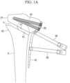
- the pressing tool 1 for bone surgeryis used in a closed wedge high tibial osteotomy (CWHTO) which involves removing a bone block from the lateral side of the tibia X, closing the bone block excision site Y to correct deformation of the tibia X, and fixing the tibia X with a bone plate (bone joining member) 10.
- CWHTOclosed wedge high tibial osteotomy
- FIGs. 1A to 1Dan example of a hybrid HTO which combines the closed wedge method and an open wedge method that involves forming an incision in the medial surface of the tibia X and expanding the incision is illustrated.
- the bone plate 10is a long strip-shaped member placed on a side surface of the tibia X so as to extend in a direction along the longitudinal axis of the tibia X.
- a plurality of screw holes 10a into which screws 20 for fixing the bone plate 10 to the tibia X are to be insertedare formed in the bone plate 10 so as to be spaced from one another in the longitudinal direction.
- Reference sign 30denotes a drill sleeve.
- the pressing tool 1 for bone surgery of this embodimentis equipped with a hook member 2 that engages with a side surface of the tibia X, and a pressing screw (pressing member) 3 that presses the bone plate 10 toward the side surface of the tibia X so as to apply a compression force to the tibia X and the bone plate 10.
- the hook member 2 and the pressing screw 3are formed of a high-strength metal such as titanium or stainless steel.
- the hook member 2includes a curved portion 4 that is curved to form a shape resembling a hook and that can engage with the side surface of the tibia X; a support portion 5 disposed at a first end of the curved portion 4 to support the pressing screw 3; and a projection portion 6 disposed at a second end of the curved portion 4 and capable of being fixed to the side surface of the tibia X.
- the curved portion 4is formed of a long columnar member and is curved to form a shape resembling a hook so as to cover half around the side surface of the tibia X from the lateral side to the medial side of the tibia X.
- the support portion 5is disposed on the lateral side of the tibia X
- the projection portion 6is disposed on the medial side of the tibia X.
- the support portion 5has a cylindrical shape having a columnar screw hole 5a that penetrates through in the longitudinal direction and has thread grooves formed in the inner surface.
- the screw hole 5aextends along a line that connects the first end and the second end of the curved portion 4, and the projection portion 6 is positioned on the extended line of a center axis (axis line) A of the screw hole 5a.
- the distance D between a middle portion between the first end and the second end of the curved portion 4 and the extended line of the center axis A of the screw hole 5ais preferably 15 mm or more and 35 mm or less so that when the curved portion 4 engages with a thick bone, such as the tibia X or the femur, the pressing screw 3 is positioned so as to be suitable for compressing the lateral surface of the bone.
- the projection portion 6projects from the second end of the curved portion 4 toward the support portion 5. As illustrated in Fig. 3 , a V-shaped groove is formed at the center of the tip of the projection portion 6, and, thus, the tip of the projection portion 6 has two pyramid-shaped projections 6a each having a pointed end 6b. The pointed ends 6b of the projections 6a are caused to bite into the side surface of the tibia X so that the projection portion 6 can be fixed relative to the tibia X.
- the number of projections 6a formed at the tip of the projection portion 6is not limited to 2 and may be 1 or 3 or more.
- one relatively large projection 6amay be provided, or as illustrated in Fig. 5 , three or more circularly arranged projections 6a may be provided.
- the pressing screw 3has a straight, columnar shaft portion 3a and a substantially spherical head portion 3b disposed at one end of the shaft portion 3a.
- the surface of the head portion 3b opposite to the shaft portion 3ais a pressing surface 3c that applies a pressing force to the bone plate 10 when fitted into a screw hole 10a in the bone plate 10. This surface is formed as a convex and substantially spherical surface.
- the shaft portion 3ais a male thread with a screw thread formed in the side surface so that the shaft portion 3a can be fastened to the screw hole 5a in the support portion 5, and is fastened to the screw hole 5a so that the pressing surface 3c of the head portion 3b faces the projection portion 6.
- the pressing screw 3moves along the center axis (axis line) of the screw hole 5a in the longitudinal direction, and the head portion 3b moves along the extended line of the center axis A of the screw hole 5a in a direction toward or away from the projection portion 6.
- the curved portion 4 of the hook member 2is allowed to engage with the side surface of the tibia X, and the projection portion 6 is fixed to the medial surface of the tibia X by allowing the pointed ends 6b of the projections 6a to bite into the medial surface of the tibia X.
- the support portion 5 supporting the pressing screw 3is placed so that the bone plate 10 is sandwiched between the lateral surface of the tibia X and the support portion 5.
- the guide pin 40is inserted into the tibia X, the guide pin 40 is inserted into the support portion 5 through the slit 2a, and thus the hook member 2 can be easily installed with respect to the tibia X and the bone plate 10.
- the slit 2amay be formed so that the guide pin 40 is inserted into and removed from the screw hole 5a via the curved portion 4.
- the slit 2amay be formed throughout the entire length from the tip of the projection portion 6 to the screw hole 5a so as to halve the curved portion 4 and the projection portion 6.
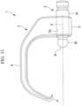
- the plug 7is equipped with a connecting portion 7a formed of a male thread that can be fastened to the screw hole 10a in the bone plate 10, and a receiving portion 7b that is disposed at one end of the connecting portion 7a and receives the head portion 3b.
- the receiving portion 7bOn the opposite side of the connecting portion 7a, the receiving portion 7b has a receiving surface 7c which is a concave and substantially spherical surface complementary to the substantially spherical pressing surface 3c of the head portion 3b and which supports the pressing surface 3c.
- the compression forcecan be efficiently transmitted to the bone plate 10 from the pressing surface 3c of the head portion 3b via the receiving surface 7c by fitting the head portion 3b to the receiving surface 7c of the plug 7, the connecting portion 7a of which is attached to the screw hole 10a in the bone plate 10.
- the solid angle of the receiving surface 7cis preferably 4 steradians or more and more preferably 2 ⁇ steradians or more. In this manner, the pressing surface 3c of the head portion 3b can be stably supported by the receiving surface 7c, and when the head portion 3b is rotated within the receiving surface 7c to adjust the direction of the compression force, displacement of the head portion 3b from the receiving surface 7c can be prevented.
- the shape of the receiving surface 7cis not limited to the concave spherical surface, and may be any other shape externally tangential to the pressing surface 3c of the head portion 3b, for example, a polygonal shape.
- a through hole 7d through which a guide pin 40 can passmay be formed in the plug 7.
- the through hole 7dpenetrates through the plug 7 along the center axis of the connecting portion 7a and opens at the center of the receiving surface 7c.
- the diameter of the through hole 7dis preferably 2 mm or more as with the diameter of the through hole 3d of the pressing screw 3.
- the projection portion 6is positioned on the extended line of the center axis A of the screw hole 5a; alternatively, as illustrated in Fig. 11 , the position of the projection portion 6 may be offset from the extended line of the center axis A of the screw hole 5a in a direction intersecting the extended line.
- a moment in a direction opposite to the offset direction of the projection portion 6 intersecting the center axis A of the screw hole 5aacts on the bone plate 10. Due to this moment, the bone plate 10 can also be moved in the bone plate 10 width direction with respect to the tibia X to adjust the position of the bone plate 10.
- a tool 50that converts a rocking motion of a grip 50a that occurs when the user grasps the grip 50a, into a motion in the longitudinal direction of the shaft portion 31a may be used.
- the structureis preferably configured so that the following relationship is established between the force Fi the user applies to the grip 50a and the force Fo acting on the pressing member 31.
- FoFi ⁇ ⁇ ⁇ ⁇ 1
- the tool 50is preferably configured to amplify the force Fi applied to the grip 50a and transmit the amplified force to the pressing member 31.
- a mechanism that prevents return motion of the grip 50amay be provided to prevent unintended return motion of the grip 50a in the opposite direction. In this manner, it becomes possible to continuously and stably apply the compression force to the tibia X and the bone plate 10.
Landscapes
- Health & Medical Sciences (AREA)
- Orthopedic Medicine & Surgery (AREA)
- Surgery (AREA)
- Life Sciences & Earth Sciences (AREA)
- Heart & Thoracic Surgery (AREA)
- Nuclear Medicine, Radiotherapy & Molecular Imaging (AREA)
- Engineering & Computer Science (AREA)
- Biomedical Technology (AREA)
- Neurology (AREA)
- Medical Informatics (AREA)
- Molecular Biology (AREA)
- Animal Behavior & Ethology (AREA)
- General Health & Medical Sciences (AREA)
- Public Health (AREA)
- Veterinary Medicine (AREA)
- Surgical Instruments (AREA)
- Prostheses (AREA)
Description
- The present invention relates to a pressing tool for bone surgery.
- Osteotomy has been applied to knee osteoarthritis, for example, when the articular cartilage of the patella or the femur is damaged. In osteotomy, after an incision is made in a bone and malalignment of the bone is corrected, the bone is fixed by using a bone joining member, such as a plate, until the bone is healed (for example, refer to PTL 1).
US 2011/0106183 A1 refers to a system that comprises a bone forceps including two elongates arms pivotally coupled to one another at a joint. The joint includes a bore extending through each of the arms with a clamping screw pivotally received therein. The clamping screw also secures an extension member to the arms. The extension member is an elongated element having a proximal end coupled to the arms and including a first section extending from the proximal end substantially parallel to the portions of the arms proximal of the joint to a second section extending away from the first section at an angle selected so that, when the arms are in a desired position gripping a fractured portion of a bone, the second section extends approximately parallel to a surface of the bone. A first bore extending through the first section is sized to receive a threaded shaft of the clamping screw therethrough. The second section includes a second bore extending therethrough configured to receive a set screw having an increased diameter head and a threaded shaft. A distal end of the threaded shaft is connected to a plate shoe via a ball joint.US 9,370,386 B2 US 2,583,896 A refers to a bone clamp including a pair of elongated body members pivotally joined in crossed relation intermediate their ends by a pivot bolt. The body members extend forwardly from said pivot to form respectively spaced apart jaw members. Formed in an inner surface of each of said jaws is a groove. Carried in each of said grooves is a clamping member. An inner surface of an upper jaw member among the jaw members is recessed at a location to provide a space between the upper jaw member and a bone immediately adjacent a clamp bar. A set screw is threaded through the upper jaw member, and is adapted to contact a plate at its inner end to hold said plate firmly in position against the bone.JP 4 493618 B2 CN 103 735 306 A discloses a pressing guide including a main support portion including a nut and a guide cylinder inserted through the nut. The guide cylinder has a through hole and a smooth and blunt cylinder tip.CN 203 970 526 U discloses an orthopedic positioner capable of adjusting an positioning point. The device includes a sliding rod and a U-shape support at the end of the sliding rod for facilitating the adjustment of the positioning point.- PTL 1 discloses a bone retainer that can retain both the bone and the bone joining member while the bone joining member is aligned with respect to the bone. According to this bone retainer, screws for fixing the bone joining member to the bone can be driven into the bone via through holes formed in a support portion that supports the bone joining member while the bone and the bone joining member are retained; thus, the task of fixing the bone joining member to the bone can be easily carried out.
- {PTL 1}
Japanese Patent Publication No. 4493618 - When fixing the bone joining member to the bone, the bone must be corrected so that the osteotomy surfaces formed at the incision are in close contact with each other, and to do so, a compression force in the longitudinal axis direction of the bone, which is the direction in which the osteotomy surfaces are drawn toward each other, must be applied to the bone from both sides of the osteotomy surfaces. However, although the bone retainer described in PTL 1 is capable of applying a compression force to the bone and the bone joining member in the bone radial direction to bring the bone and the bone joining member into close contact with each other, the bone retainer cannot apply a force to the bone in the longitudinal axis direction and has a problem in that it is difficult to correct the bone so that the osteotomy surfaces are in close contact with each other.
- The present invention has been made under the circumstances described above, and an object thereof is to provide a pressing tool for bone surgery, with which a compression force can be applied in both the bone radial direction and longitudinal axis direction so that close contact can be achieved between the bone and the bone joining member and between the osteotomy surfaces of the bone.
- In order to achieve the object described above, the present invention provides the following solution.
- The present invention provides a pressing tool as defined in claim 1. Preferred embodiments are defined by the dependent claims. Associated methods are also described herein to aid understanding of the invention, but these do not form part of the claimed invention.
- In one aspect, a pressing tool for bone surgery may comprise: a pressurizing member formed substantially columnar shape having, at one end, a pressing surface formed of a convex and substantially spherical surface; and a hook member formed to have a hook shape that is to be engaged with a surface of a bone, the hook member having a support portion at a first end, the support portion supporting the pressing member so that the pressing surface is directed toward a second end, and a projection portion at the second end, the projection portion projecting toward the support portion and being to be bited into the surface of the bone, wherein the support portion supports the pressing member so that the pressing member is movable in a longitudinal direction toward the projection portion.
- According to the aforementioned aspect, after a bone joining member is placed on a surface of the bone in which an incision is made so as to bridge the incision, the hook member engages with the surface of the bone in such a manner that the bone and the bone joining member are sandwiched in the bone radial direction between the projection portion and the support portion at two ends of the hook member, and the projection portion is allowed to bite into the surface of the bone to fix the projection portion to the surface of the bone. The pressing member supported by the support portion is moved toward the projection portion in such a manner that the pressing surface presses the bone joining member toward the bone. As a result, a compression force in the bone radial direction is applied to the bone and the bone joining member sandwiched between the projection portion and the pressing member, and thus the bone and the bone joining member can make close contact with each other.
- In this case, the direction in which the compression force is applied to the bone and the bone joining member is coincident with the direction in which the pressing member moves. Thus, when the hook member engages with the surface of the bone so that the longitudinal direction of the pressing member is inclined relative to the longitudinal axis direction of the bone, a compression force in both the bone radial direction and longitudinal axis direction is applied, and close contact can be achieved between the bone and the bone joining member and between the osteotomy surfaces of the bone.
- Furthermore, in a state in which the hook member is engaged with the bone so that the pressing member is inclined with respect to the longitudinal axis direction of the bone, a large compression force can be stably applied to the bone and the bone joining member between the projection portion and the pressing member by fixing the projection portion at the second end of the hook member to the surface of the bone. In addition, since the pressing surface contacting the bone joining member is substantially spherical, the orientation of the hook member can be easily changed by rotating the pressing surface at the same position relative to the bone joining member and by shifting the projection portion in the longitudinal axis direction of the bone.
- In the aspect described above, the pressing member has a male thread and a head portion that is disposed at one end of the male thread and has the pressing surface, and the support portion has a screw hole to be fastened to the male thread.
- In this manner, since the rotation of the male thread inside the screw hole is converted into movement of the shaft portion in the longitudinal direction, it is easy to finely adjust the amount of the movement of the male thread to control the compression force applied to the bone and the bone joining member.
- In the aspect described above, the projection portion may be positioned on an extended line of an axis line along which the pressing member is movable.
- In this manner, only a pressing force in the longitudinal direction of the pressing member can be applied to the bone joining member.
- In the aspect described above, the projection portion may be at a position offset from an extended line of an axis line along which the pressing member is movable, in a direction intersecting the extended line.
- In this manner, in addition to the pressing force in the longitudinal direction of the pressing member, a moment in a direction opposite to the offset direction of the projection portion intersecting the longitudinal direction of the pressing member can be applied to the bone joining member, and thus the bone joining member can be moved not only in a direction toward the bone but also in a direction opposite to the offset direction of the projection portion.
- In the aspect described above, a distance between an extended line of an axis line along which the pressing member is movable and a middle portion of the hook member may be 15 mm or more and 35 mm or less.
- In this manner, the size of the hook member becomes suitable for a large bone, such as the femur or the tibia.
- In the aspect described above, the projection portion may have one or more pyramid-shaped projections having pointed ends.
- In this manner, the pointed ends of the projections bite into the hard cortical bone covering the surface of the bone, and the projection portion can be easily fixed thereby.
- In the aspect described above, the hook member has a slit that allows an interior of the screw hole and an exterior of the support portion to communicate with each other in a radial direction of the screw hole and that extends in a direction along a center axis of the screw hole, wherein a guide pin is inserted into the screw hole in the radial direction.
- In this manner, the hook member can be easily installed relative to the guide pin preliminarily inserted into the bone.
- In the aspect described above, the pressing tool may further include a plug having a receiving portion having a concave receiving surface that supports the pressing surface, and a connecting portion that can connect the receiving portion to a bone joining member that is to be fixed to the surface of the bone.
- In this manner, compared to the case in which the pressing surface is directly pressed against the bone joining member, the position of the pressing surface relative to the bone joining member can be stabilized by fitting the pressing surface to the receiving surface of the receiving portion of the plug connected to the bone joining member, and a pressing force can more efficiently be applied from the pressing surface to the bone joining member.
- In the aspect described above, the plug may have a through hole that opens substantially at the center of the receiving surface and allows a guide pin to pass therethrough.
- In this manner, the guide pin inserted into the bone passes through the bone joining member, the plug, and the pressing member, and thus, the positions of the bone joining member, the plug, and the pressing member relative to the bone can be stabilized. Considering the diameter of the guide pin typically used in osteotomy, the diameter of the through hole of the plug is preferably 2 mm or more.
- In the aspect described above, the receiving surface of the receiving portion may have a solid angle of 4 steradians or more.
- In this manner, the surface of the head portion opposite from the shaft portion can be more stably supported by the receiving surface, and a pressing force can be reliably applied from the pressing member to the bone joining member. The solid angle of the receiving surface is more preferably 2π steradians or more so that no less than half of the outer surface of the head portion can be supported by the receiving surface.
- The present invention affords advantageous effects in that compression force can be applied in both the bone radial direction and longitudinal axis direction so that close contact can be achieved between the bone and the bone joining member and between the osteotomy surfaces of the bone.
- {
Fig. 1A }Fig. 1A is a diagram illustrating a high tibial osteotomy that uses a pressing tool for bone surgery according to one embodiment of the present invention. - {
Fig. 1B }Fig. 1B is a diagram illustrating the tibia illustrated inFig. 1A as viewed from the bone plate side. - {
Fig. 1C }Fig. 1C is a diagram illustrating the high tibial osteotomy that uses the pressing tool for bone surgery according to one embodiment of the present invention. - {
Fig. 1D }Fig. 1D is a diagram illustrating the high tibial osteotomy that uses the pressing tool for bone surgery according to one embodiment of the present invention. - {
Fig. 2 }Fig. 2 is a side view illustrating the overall structure of the pressing tool for bone surgery according to one embodiment of the present invention. - {
Fig. 3 }Fig. 3 is a perspective view of a projection portion of a hook member of the pressing tool for bone surgery illustrated inFig. 2 . - {
Fig. 4 }Fig. 4 is a perspective view of a modification of the projection portion of the hook member. - {
Fig. 5 }Fig. 5 is a perspective view of another modification of the projection portion of the hook member. - {
Fig. 6 }Fig. 6 is a diagram illustrating a method for changing the direction of the compression force applied to the tibia and the bone plate by using the pressing tool for bone surgery illustrated inFig. 2 . - {
Fig. 7 }Fig. 7 is a diagram illustrating a method for using the modification of the pressing tool for bone surgery illustrated inFig. 2 in combination with a guide pin. - {
Fig. 8 }Fig. 8 is a perspective view of a modification of a hook member having a slit. - {
Fig. 9 }Fig. 9 is a perspective view of another modification of the hook member having a slit. - {
Fig. 10 }Fig. 10 is a side view of a plug installed in a modification of the pressing tool for bone surgery illustrated inFig. 2 . - {
Fig. 11 }Fig. 11 is a side view of another modification of the hook member. - {
Fig. 12 }Fig. 12 is a diagram illustrating a modification of a pressing member and a pressing means. - In the description below, a pressing tool 1 for bone surgery according to one embodiment of the present invention is described with reference to the drawings.
- As illustrated in
Figs. 1A to 1D , the pressing tool 1 for bone surgery according to this embodiment is used in a closed wedge high tibial osteotomy (CWHTO) which involves removing a bone block from the lateral side of the tibia X, closing the bone block excision site Y to correct deformation of the tibia X, and fixing the tibia X with a bone plate (bone joining member) 10. InFigs. 1A to 1D , an example of a hybrid HTO which combines the closed wedge method and an open wedge method that involves forming an incision in the medial surface of the tibia X and expanding the incision is illustrated. - As illustrated in
Fig. 1B , thebone plate 10 is a long strip-shaped member placed on a side surface of the tibia X so as to extend in a direction along the longitudinal axis of the tibia X. A plurality ofscrew holes 10a into which screws 20 for fixing thebone plate 10 to the tibia X are to be inserted are formed in thebone plate 10 so as to be spaced from one another in the longitudinal direction.Reference sign 30 denotes a drill sleeve. - As illustrated in
Fig. 2 , the pressing tool 1 for bone surgery of this embodiment is equipped with ahook member 2 that engages with a side surface of the tibia X, and a pressing screw (pressing member) 3 that presses thebone plate 10 toward the side surface of the tibia X so as to apply a compression force to the tibia X and thebone plate 10. Thehook member 2 and thepressing screw 3 are formed of a high-strength metal such as titanium or stainless steel. - The
hook member 2 includes acurved portion 4 that is curved to form a shape resembling a hook and that can engage with the side surface of the tibia X; asupport portion 5 disposed at a first end of thecurved portion 4 to support thepressing screw 3; and aprojection portion 6 disposed at a second end of thecurved portion 4 and capable of being fixed to the side surface of the tibia X. - The
curved portion 4 is formed of a long columnar member and is curved to form a shape resembling a hook so as to cover half around the side surface of the tibia X from the lateral side to the medial side of the tibia X. In a state in which thecurved portion 4 is allowed to engage with the side surface of the tibia X along the circumferential direction, thesupport portion 5 is disposed on the lateral side of the tibia X, and theprojection portion 6 is disposed on the medial side of the tibia X. - The
support portion 5 has a cylindrical shape having acolumnar screw hole 5a that penetrates through in the longitudinal direction and has thread grooves formed in the inner surface. Thescrew hole 5a extends along a line that connects the first end and the second end of thecurved portion 4, and theprojection portion 6 is positioned on the extended line of a center axis (axis line) A of thescrew hole 5a. The distance D between a middle portion between the first end and the second end of thecurved portion 4 and the extended line of the center axis A of thescrew hole 5a is preferably 15 mm or more and 35 mm or less so that when thecurved portion 4 engages with a thick bone, such as the tibia X or the femur, thepressing screw 3 is positioned so as to be suitable for compressing the lateral surface of the bone. - The
projection portion 6 projects from the second end of thecurved portion 4 toward thesupport portion 5. As illustrated inFig. 3 , a V-shaped groove is formed at the center of the tip of theprojection portion 6, and, thus, the tip of theprojection portion 6 has two pyramid-shapedprojections 6a each having apointed end 6b. The pointed ends 6b of theprojections 6a are caused to bite into the side surface of the tibia X so that theprojection portion 6 can be fixed relative to the tibia X. - The number of
projections 6a formed at the tip of theprojection portion 6 is not limited to 2 and may be 1 or 3 or more. For example, as illustrated inFig. 4 , one relativelylarge projection 6a may be provided, or as illustrated inFig. 5 , three or more circularly arrangedprojections 6a may be provided. - The
pressing screw 3 has a straight,columnar shaft portion 3a and a substantiallyspherical head portion 3b disposed at one end of theshaft portion 3a. The surface of thehead portion 3b opposite to theshaft portion 3a is apressing surface 3c that applies a pressing force to thebone plate 10 when fitted into ascrew hole 10a in thebone plate 10. This surface is formed as a convex and substantially spherical surface. - The
shaft portion 3a is a male thread with a screw thread formed in the side surface so that theshaft portion 3a can be fastened to thescrew hole 5a in thesupport portion 5, and is fastened to thescrew hole 5a so that thepressing surface 3c of thehead portion 3b faces theprojection portion 6. As theshaft portion 3a rotates about the center axis thereof, thepressing screw 3 moves along the center axis (axis line) of thescrew hole 5a in the longitudinal direction, and thehead portion 3b moves along the extended line of the center axis A of thescrew hole 5a in a direction toward or away from theprojection portion 6. - Next, the effects of the pressing tool 1 for bone surgery having the aforementioned structure are described.
- In order to treat knee osteoarthritis by the hybrid HTO technique using the pressing tool 1 for bone surgery of this embodiment, two incisions are formed from the upper lateral surface in the tibia X toward the medial side in directions oblique with respect to the longitudinal axis of the tibia X, and a bone block between two incisions is excised with a particular tool. Next, as illustrated in
Figs. 1A and1B , thebone plate 10 is placed on the lateral surface of the tibia X so as to bridge the bone block excision site Y, and an upper end portion of thebone plate 10 is fixed with thescrews 20 to the tibia X at a position higher than the excision site Y. - Next, as illustrated in
Fig. 1C , thecurved portion 4 of thehook member 2 is allowed to engage with the side surface of the tibia X, and theprojection portion 6 is fixed to the medial surface of the tibia X by allowing the pointed ends 6b of theprojections 6a to bite into the medial surface of the tibia X. In addition, thesupport portion 5 supporting thepressing screw 3 is placed so that thebone plate 10 is sandwiched between the lateral surface of the tibia X and thesupport portion 5. - Next, the
pressing surface 3c of thehead portion 3b is fitted into thescrew hole 10a located on the lower side of the excision site Y, and theshaft portion 3a is rotated to advance thepressing screw 3 toward thebone plate 10. As a result, the distance between thehead portion 3b and theprojection portion 6 is shortened, and the tibia X and thebone plate 10 sandwiched between thehead portion 3b and theprojection portion 6 are compressed by thehead portion 3b and theprojection portion 6 and move close to each other. At this stage, since theprojection portion 6 is located on the extended line of the center axis A of thescrew hole 5a in which thepressing screw 3 moves, only a compression force working in the center axis A direction of thescrew hole 5a, which is the direction in which thepressing screw 3 moves, is applied to the tibia X and thebone plate 10, and the tibia X and thebone plate 10 move only in the center axis A direction. - As illustrated in
Fig. 1D , after theshaft portion 3a has been rotated until thebone plate 10 is in close contact with the lateral surface of the tibia X, thescrews 20 are inserted into the rest of thescrew holes 10a in thebone plate 10 to fix thebone plate 10 to the tibia X. - In this case, when aligning the tibia X and the
bone plate 10, as illustrated inFig. 1D , two portions, X1 and X2, of the tibia X respectively located on the higher side and the lower side of the excision site Y of the tibia X must be aligned so that the two osteotomy surfaces Y1 and Y2 at the excision site Y of the tibia X come into close contact with each other. In other words, a compression force in the longitudinal axis direction must be applied to the tibia X so that the higher portion X1 and the lower portion X2 are drawn toward each other. - According to this embodiment, as described above, the direction of the compression force applied to the tibia X and the
bone plate 10 is coincident with the center axis A direction of thescrew hole 5a; thus, as illustrated inFig. 6 , the direction of the compression force can be easily controlled to a desired direction by adjusting the inclination angle of the center axis A of thescrew hole 5a with respect to the longitudinal axis of the tibia X. - In other words, by placing the
hook member 2 so that the center axis A of thescrew hole 5a is inclined with respect to the longitudinal axis of the tibia X, a compression force in a direction oblique to the longitudinal axis of the tibia X is applied to the tibia X and thebone plate 10 so that a compression force in the tibia X radial direction that draws the tibia X and thebone plate 10 close to each other can be generated, and, at the same time, a compression force in the longitudinal axis direction, which is the direction in which the higher portion X1 and the lower portion X2 of the tibia X are drawn toward each other, can be generated. Increasing the inclination angle of the center axis A of thescrew hole 5a with respect to the longitudinal axis of the tibia X increases the compression force in the longitudinal axis direction. As such, there is an advantage in that, by applying a compression force in both the direction in which the tibia X and thebone plate 10 are drawn close to each other and the direction in which the osteotomy surfaces Y1 and Y2 are drawn close to each other, the relative position between the three parts, i.e., the higher portion X1 and the lower portion X2 of the tibia X and thebone plate 10, can be adjusted so as to eliminate the gap between the osteotomy surfaces Y1 and Y2. - Moreover, the direction of the compression force can be changed merely by temporarily detaching the pointed ends 6b biting into the tibia X from the tibia X, then shifting the position of the
projection portion 6 in the tibia X longitudinal axis direction, and then allowing the pointed ends 6b to again bite into the tibia X. During this process, since thepressing surface 3c of thehead portion 3b is spherical, the position of theprojection portion 6 can be easily shifted by using thehead portion 3b as the supporting point and by rotating thehead portion 3b in thescrew hole 10a. As such, there is an advantage in that the direction of the compression force applied to the tibia X and thebone plate 10 can be easily changed. - Also, there is an advantage in that if alignment of the higher portion X1 and the lower portion X2 of the tibia X and the
bone plate 10 was not successfully carried out in the first attempt, the compressing operation can be easily repeated by rotating theshaft portion 3a in the opposite direction to retract thepressing screw 3 to the side opposite from thebone plate 10. - In this embodiment, as illustrated in
Fig. 7 , a throughhole 3d through which aguide pin 40 can pass may be formed in thepressing screw 3 so as to pass therethrough along the center axis of theshaft portion 3a so that the pressing tool 1 for bone surgery can be used in combination with theguide pin 40 of thescrew 20. Considering the diameter of theguide pin 40 typically used in HTO, the diameter of the throughhole 3d is preferably 2 mm or more. - In this manner, since the
pressing screw 3 is guided along theguide pin 40 inserted into the throughhole 3d, the position and the orientation of thepressing screw 3 with respect to the tibia X and thebone plate 10 can be stabilized. - Furthermore, as illustrated in
Fig. 8 , aslit 2a for inserting and removing theguide pin 40 into and from inside thesupport portion 5 in the radial direction is formed in thehook member 2. Theslit 2a extends from the outer circumferential surface to the inner circumferential surface of thesupport portion 5 so that the interior of thescrew hole 5a communicates with the exterior of thesupport portion 5, and is formed throughout the entire length in the longitudinal direction. - According to the
hook member 2 having thisslit 2a, after theguide pin 40 is inserted into the tibia X, theguide pin 40 is inserted into thesupport portion 5 through theslit 2a, and thus thehook member 2 can be easily installed with respect to the tibia X and thebone plate 10. - As illustrated in
Fig. 9 , theslit 2a may be formed so that theguide pin 40 is inserted into and removed from thescrew hole 5a via thecurved portion 4. In other words, theslit 2a may be formed throughout the entire length from the tip of theprojection portion 6 to thescrew hole 5a so as to halve thecurved portion 4 and theprojection portion 6. - In this embodiment, the
head portion 3b of thepressing screw 3 is directly fitted into thescrew hole 10a of thebone plate 10; alternatively, as illustrated inFig. 7 , aplug 7 that can be attached to thescrew hole 10a and supports thehead portion 3b may be further provided. - As illustrated in
Fig. 10 , theplug 7 is equipped with a connectingportion 7a formed of a male thread that can be fastened to thescrew hole 10a in thebone plate 10, and a receivingportion 7b that is disposed at one end of the connectingportion 7a and receives thehead portion 3b. On the opposite side of the connectingportion 7a, the receivingportion 7b has a receivingsurface 7c which is a concave and substantially spherical surface complementary to the substantially sphericalpressing surface 3c of thehead portion 3b and which supports thepressing surface 3c. - The compression force can be efficiently transmitted to the
bone plate 10 from thepressing surface 3c of thehead portion 3b via the receivingsurface 7c by fitting thehead portion 3b to the receivingsurface 7c of theplug 7, the connectingportion 7a of which is attached to thescrew hole 10a in thebone plate 10. - The solid angle of the receiving
surface 7c is preferably 4 steradians or more and more preferably 2π steradians or more. In this manner, thepressing surface 3c of thehead portion 3b can be stably supported by the receivingsurface 7c, and when thehead portion 3b is rotated within the receivingsurface 7c to adjust the direction of the compression force, displacement of thehead portion 3b from the receivingsurface 7c can be prevented. - The shape of the receiving
surface 7c is not limited to the concave spherical surface, and may be any other shape externally tangential to thepressing surface 3c of thehead portion 3b, for example, a polygonal shape. - To enable use of the
plug 7 in combination with theguide pin 40, a throughhole 7d through which aguide pin 40 can pass may be formed in theplug 7. The throughhole 7d penetrates through theplug 7 along the center axis of the connectingportion 7a and opens at the center of the receivingsurface 7c. The diameter of the throughhole 7d is preferably 2 mm or more as with the diameter of the throughhole 3d of thepressing screw 3. - In this manner, the
screw hole 10a and theguide pin 40 passing through the throughholes bone plate 10, theplug 7, and thepressing screw 3 relative to the tibia X. - In this embodiment, the
projection portion 6 is positioned on the extended line of the center axis A of thescrew hole 5a; alternatively, as illustrated inFig. 11 , the position of theprojection portion 6 may be offset from the extended line of the center axis A of thescrew hole 5a in a direction intersecting the extended line. - In this case, a moment in a direction opposite to the offset direction of the
projection portion 6 intersecting the center axis A of thescrew hole 5a acts on thebone plate 10. Due to this moment, thebone plate 10 can also be moved in thebone plate 10 width direction with respect to the tibia X to adjust the position of thebone plate 10. - In this embodiment, physical power of the user is used as the driving force for advancing and retracting the
pressing screw 3; alternatively, thepressing screw 3 may be moved by using oil pressure or water pressure, or by using an electric motor. - Moreover, in this embodiment, the
pressing screw 3 is used as the pressing member for pushing thebone plate 10 and generating a compression force; alternatively, a different pressing member may be used. For example, as illustrated inFig. 12 , a pressingmember 31 may be equipped with ashaft portion 31a having a smooth side surface instead of themale thread 3a. In this case, asupport portion 51 may have, instead of thescrew hole 5a, aguide hole 51a which has a smooth inner surface and into which theshaft portion 31a of the pressing member fits so as to be movable in the longitudinal direction. Theshaft portion 31a may be driven by using a tool that converts a particular motion of the user into a motion in the longitudinal direction of theshaft portion 31a. - For example, as illustrated in
Fig. 12 , atool 50 that converts a rocking motion of agrip 50a that occurs when the user grasps thegrip 50a, into a motion in the longitudinal direction of theshaft portion 31a may be used. The structure is preferably configured so that the following relationship is established between the force Fi the user applies to thegrip 50a and the force Fo acting on the pressingmember 31.
- In other words, the
tool 50 is preferably configured to amplify the force Fi applied to thegrip 50a and transmit the amplified force to the pressingmember 31. - A mechanism that prevents return motion of the
grip 50a may be provided to prevent unintended return motion of thegrip 50a in the opposite direction. In this manner, it becomes possible to continuously and stably apply the compression force to the tibia X and thebone plate 10. - 1 pressing tool for bone surgery
- 2 hook member
- 2a slit
- 3 pressing screw (pressing member)
- 3a shaft portion
- 3b head portion
- 3c pressing surface
- 3d through hole
- 4 curved portion
- 5 support portion
- 5a screw hole
- 6 projection portion
- 6a projection
- 6b pointed end
- 7 plug
- 7a connecting portion
- 7b receiving portion
- 7c receiving surface
- 7d through hole
- 10 bone plate (bone joining member)
- 10a screw hole
- 20 screw
- 30 drill sleeve
- 40 guide pin
- A center line (axis line) of screw hole
- X tibia
- X1 higher portion
- X2 lower portion
- Y bone block removed portion
- Y1, Y2 osteotomy surface

Claims (8)
- A pressing tool (1) for bone surgery, comprising:a pressing member (3) formed in a columnar shape shaft along a longitudinal axis having, at one end, a pressing surface (3c) formed of a convex and spherical surface and a male thread extending from the pressing surface (3c) in a longitudinal direction; anda hook member (2) that has a curved portion (4) being curved to form a hook shape configured to cover half around a side surface of a bone and to engage with the side surface of the bone, the hook member having a cylindrical support portion (5) provided at a first end of the curved portion (4) configured to support the pressing member (3) so that the pressing surface (3c) is directed toward a second end of the curved portion (4), the hook member having a projection portion (6) at the second end, the projection portion (6) projecting toward the support portion (5) and being configured to bite into the side surface of the bone,wherein the support portion (5) has a screw hole (5a) extending in the longitudinal direction and supports the pressing member (3) in state of the pressing member (3) is movable in the longitudinal direction toward the projection portion (6) by the male thread being fastened to the screw hole (5a),wherein the support portion (5) has a slit (2a) that extends from an outer circumferential surface to an inner circumferential surface of the support portion (5) so that an interior of the screw hole (5a) communicates with an exterior of the support portion (5) in a radial direction of the screw hole (5a), the slit (2a) being formed throughout an entire length of the support portion (5) in the longitudinal direction, andwherein a guide pin (40) is inserted into the support portion (5) in the radial direction through the slit (2a).
- The pressing tool for bone surgery according to Claim 1, wherein the projection portion (6) is positioned on an extended line of an axis line (A) along which the pressing member (3) is movable.
- The pressing tool for bone surgery according to Claim 1, wherein the projection portion (6) is at a position offset from an extended line of an axis line (A), along which the pressing member (3) is movable, in a direction intersecting the extended line.
- The pressing tool for bone surgery according to any one of Claims 1 to 3, wherein a distance (D) between an extended line of an axis line (A) along which the pressing member (3) is movable and a middle portion of the hook member (2) is 15 mm or more and 35 mm or less.
- The pressing tool for bone surgery according to any one of Claims 1 to 4, wherein the projection portion (6) has one or more pyramid-shaped projections (6a) having pointed ends (6b).
- The pressing tool for bone surgery according to any one of Claims 1 to 5, further comprising a plug (7) having a receiving portion (7b) having a concave receiving surface (7c) that supports the pressing surface (3c), and a connecting portion (7a) that can connect the receiving portion (7b) to a bone joining member (10) that is to be fixed to the side surface of the bone.
- The pressing tool for bone surgery according to Claim 6, wherein the plug (7) has a through hole (7d) that opens at the center of the receiving surface (7c) and allows a guide pin (40) to pass therethrough.
- The pressing tool for bone surgery according to Claim 6 or 7, wherein the receiving surface (7c) of the receiving portion (7b) has a solid angle of 4 steradians or more.
Applications Claiming Priority (2)
| Application Number | Priority Date | Filing Date | Title |
|---|---|---|---|
| US201662366153P | 2016-07-25 | 2016-07-25 | |
| PCT/JP2017/026224WO2018021134A1 (en) | 2016-07-25 | 2017-07-20 | Pressing instrument to be used in bone surgery |
Publications (3)
| Publication Number | Publication Date |
|---|---|
| EP3488804A1 EP3488804A1 (en) | 2019-05-29 |
| EP3488804A4 EP3488804A4 (en) | 2020-04-08 |
| EP3488804B1true EP3488804B1 (en) | 2024-11-20 |
Family
ID=61016190
Family Applications (1)
| Application Number | Title | Priority Date | Filing Date |
|---|---|---|---|
| EP17834142.6AActiveEP3488804B1 (en) | 2016-07-25 | 2017-07-20 | Pressing instrument to be used in bone surgery |
Country Status (8)
| Country | Link |
|---|---|
| US (1) | US11076899B2 (en) |
| EP (1) | EP3488804B1 (en) |
| JP (1) | JP6936799B2 (en) |
| KR (1) | KR102263943B1 (en) |
| CN (1) | CN109475376B (en) |
| PH (1) | PH12019500164A1 (en) |
| SG (1) | SG11201900308PA (en) |
| WO (1) | WO2018021134A1 (en) |
Families Citing this family (2)
| Publication number | Priority date | Publication date | Assignee | Title |
|---|---|---|---|---|
| CA3078902A1 (en)* | 2017-11-30 | 2019-06-06 | DePuy Synthes Products, Inc. | Bone fracture fixation clamp with bone remodeling adaptability |
| CN113453634A (en)* | 2019-02-20 | 2021-09-28 | 史密夫和内修有限公司 | Systems and methods for high tibial osteotomy |
Citations (2)
| Publication number | Priority date | Publication date | Assignee | Title |
|---|---|---|---|---|
| CN103735306A (en)* | 2014-01-04 | 2014-04-23 | 邓宇 | Frame-type pressurizing multipurpose guider |
| CN203970526U (en)* | 2013-12-20 | 2014-12-03 | 山东省立医院 | A kind of orthopaedics localizer of scalable anchor point |
Family Cites Families (15)
| Publication number | Priority date | Publication date | Assignee | Title |
|---|---|---|---|---|
| US2583896A (en)* | 1949-09-06 | 1952-01-29 | Siebrandt Inc | Bone clamp |
| WO1999045856A1 (en) | 1998-03-13 | 1999-09-16 | Macey Theodore I | Method and apparatus for clamping |
| US6679888B2 (en) | 2001-05-29 | 2004-01-20 | Synthes | Femur lever |
| US7776076B2 (en) | 2004-05-11 | 2010-08-17 | Synthes Usa, Llc | Bone plate |
| US7951176B2 (en) | 2003-05-30 | 2011-05-31 | Synthes Usa, Llc | Bone plate |
| JP4493618B2 (en) | 2006-03-23 | 2010-06-30 | ノアスメディカル株式会社 | Bone retainer |
| CN101103936A (en)* | 2006-07-12 | 2008-01-16 | 张长青 | Clamper for bone fixing plate |
| DE202008000914U1 (en)* | 2008-01-22 | 2008-03-20 | Stryker Trauma Gmbh | Kirschner wire clamp |
| EP2323568A1 (en)* | 2008-07-29 | 2011-05-25 | Synthes GmbH | Plate holding bone forceps and method of use |
| JP2013512042A (en) | 2009-11-27 | 2013-04-11 | シンセス ゲゼルシャフト ミット ベシュレンクテル ハフツング | Planar fixation concept for distal radius fractures |
| WO2013191819A1 (en) | 2012-06-20 | 2013-12-27 | DePuy Synthes Products, LLC | Soft tissue bone reduction forceps |
| US9610084B2 (en)* | 2012-09-12 | 2017-04-04 | Peter Michael Sutherland Walker | Method and apparatus for hip replacements |
| AU2013228016A1 (en) | 2012-09-12 | 2014-03-27 | Peter Michael Sutherland Walker | Improved method and apparatus for hip replacements |
| US20150313640A1 (en)* | 2014-04-30 | 2015-11-05 | Andres Eduardo O'DALY | Surgical instrument with movable guide and sleeve |
| US10299806B2 (en)* | 2016-03-21 | 2019-05-28 | Alexander D. Kim | Bone clamp |
- 2017
- 2017-07-20JPJP2018529821Apatent/JP6936799B2/enactiveActive
- 2017-07-20CNCN201780045650.XApatent/CN109475376B/enactiveActive
- 2017-07-20KRKR1020197001480Apatent/KR102263943B1/enactiveActive
- 2017-07-20WOPCT/JP2017/026224patent/WO2018021134A1/ennot_activeCeased
- 2017-07-20EPEP17834142.6Apatent/EP3488804B1/enactiveActive
- 2017-07-20SGSG11201900308PApatent/SG11201900308PA/enunknown
- 2019
- 2019-01-23USUS16/254,669patent/US11076899B2/enactiveActive
- 2019-01-23PHPH12019500164Apatent/PH12019500164A1/enunknown
Patent Citations (2)
| Publication number | Priority date | Publication date | Assignee | Title |
|---|---|---|---|---|
| CN203970526U (en)* | 2013-12-20 | 2014-12-03 | 山东省立医院 | A kind of orthopaedics localizer of scalable anchor point |
| CN103735306A (en)* | 2014-01-04 | 2014-04-23 | 邓宇 | Frame-type pressurizing multipurpose guider |
Also Published As
| Publication number | Publication date |
|---|---|
| WO2018021134A1 (en) | 2018-02-01 |
| JP6936799B2 (en) | 2021-09-22 |
| EP3488804A1 (en) | 2019-05-29 |
| KR20190020051A (en) | 2019-02-27 |
| KR102263943B1 (en) | 2021-06-11 |
| PH12019500164A1 (en) | 2019-10-28 |
| EP3488804A4 (en) | 2020-04-08 |
| US20190175235A1 (en) | 2019-06-13 |
| CN109475376A (en) | 2019-03-15 |
| US11076899B2 (en) | 2021-08-03 |
| CN109475376B (en) | 2022-03-22 |
| JPWO2018021134A1 (en) | 2019-05-09 |
| SG11201900308PA (en) | 2019-02-27 |
Similar Documents
| Publication | Publication Date | Title |
|---|---|---|
| US11806008B2 (en) | Devices for generating and applying compression within a body | |
| US11452555B2 (en) | Bone fracture fixation clamp | |
| KR101602326B1 (en) | Plate holding bone forceps and method of use | |
| CN107028650B (en) | Fracture fixing clamp | |
| US8685037B1 (en) | Bone reduction and plate clamp assembly | |
| CN106413575B (en) | Staple for creating and applying compression in vivo | |
| EP2689737B1 (en) | Surgical reduction clamp | |
| US8579950B1 (en) | Bone reduction and plate clamp assembly | |
| CN100542496C (en) | Compressor-retractor | |
| CN111493994B (en) | Bone reduction clamp and plate holding clamp | |
| CN104510520B (en) | reduction forceps | |
| EP3488804B1 (en) | Pressing instrument to be used in bone surgery | |
| US6921404B2 (en) | Universal device and method for supporting bones and surgery tools in orthopaedic surgery | |
| US12295625B2 (en) | Apparatus and methods for joining bones |
Legal Events
| Date | Code | Title | Description |
|---|---|---|---|
| STAA | Information on the status of an ep patent application or granted ep patent | Free format text:STATUS: THE INTERNATIONAL PUBLICATION HAS BEEN MADE | |
| PUAI | Public reference made under article 153(3) epc to a published international application that has entered the european phase | Free format text:ORIGINAL CODE: 0009012 | |
| STAA | Information on the status of an ep patent application or granted ep patent | Free format text:STATUS: REQUEST FOR EXAMINATION WAS MADE | |
| 17P | Request for examination filed | Effective date:20190221 | |
| AK | Designated contracting states | Kind code of ref document:A1 Designated state(s):AL AT BE BG CH CY CZ DE DK EE ES FI FR GB GR HR HU IE IS IT LI LT LU LV MC MK MT NL NO PL PT RO RS SE SI SK SM TR | |
| AX | Request for extension of the european patent | Extension state:BA ME | |
| DAV | Request for validation of the european patent (deleted) | ||
| DAX | Request for extension of the european patent (deleted) | ||
| A4 | Supplementary search report drawn up and despatched | Effective date:20200305 | |
| RIC1 | Information provided on ipc code assigned before grant | Ipc:A61B 17/90 20060101AFI20200228BHEP Ipc:A61B 17/80 20060101ALI20200228BHEP | |
| STAA | Information on the status of an ep patent application or granted ep patent | Free format text:STATUS: EXAMINATION IS IN PROGRESS | |
| 17Q | First examination report despatched | Effective date:20230118 | |
| P01 | Opt-out of the competence of the unified patent court (upc) registered | Effective date:20230528 | |
| GRAP | Despatch of communication of intention to grant a patent | Free format text:ORIGINAL CODE: EPIDOSNIGR1 | |
| STAA | Information on the status of an ep patent application or granted ep patent | Free format text:STATUS: GRANT OF PATENT IS INTENDED | |
| INTG | Intention to grant announced | Effective date:20240624 | |
| GRAS | Grant fee paid | Free format text:ORIGINAL CODE: EPIDOSNIGR3 | |
| GRAA | (expected) grant | Free format text:ORIGINAL CODE: 0009210 | |
| STAA | Information on the status of an ep patent application or granted ep patent | Free format text:STATUS: THE PATENT HAS BEEN GRANTED | |
| AK | Designated contracting states | Kind code of ref document:B1 Designated state(s):AL AT BE BG CH CY CZ DE DK EE ES FI FR GB GR HR HU IE IS IT LI LT LU LV MC MK MT NL NO PL PT RO RS SE SI SK SM TR | |
| REG | Reference to a national code | Ref country code:GB Ref legal event code:FG4D | |
| REG | Reference to a national code | Ref country code:CH Ref legal event code:EP | |
| REG | Reference to a national code | Ref country code:DE Ref legal event code:R096 Ref document number:602017086281 Country of ref document:DE | |
| REG | Reference to a national code | Ref country code:IE Ref legal event code:FG4D | |
| REG | Reference to a national code | Ref country code:LT Ref legal event code:MG9D | |
| REG | Reference to a national code | Ref country code:NL Ref legal event code:MP Effective date:20241120 | |
| PG25 | Lapsed in a contracting state [announced via postgrant information from national office to epo] | Ref country code:HR Free format text:LAPSE BECAUSE OF FAILURE TO SUBMIT A TRANSLATION OF THE DESCRIPTION OR TO PAY THE FEE WITHIN THE PRESCRIBED TIME-LIMIT Effective date:20241120 Ref country code:PT Free format text:LAPSE BECAUSE OF FAILURE TO SUBMIT A TRANSLATION OF THE DESCRIPTION OR TO PAY THE FEE WITHIN THE PRESCRIBED TIME-LIMIT Effective date:20250320 Ref country code:IS Free format text:LAPSE BECAUSE OF FAILURE TO SUBMIT A TRANSLATION OF THE DESCRIPTION OR TO PAY THE FEE WITHIN THE PRESCRIBED TIME-LIMIT Effective date:20250320 | |
| PG25 | Lapsed in a contracting state [announced via postgrant information from national office to epo] | Ref country code:FI Free format text:LAPSE BECAUSE OF FAILURE TO SUBMIT A TRANSLATION OF THE DESCRIPTION OR TO PAY THE FEE WITHIN THE PRESCRIBED TIME-LIMIT Effective date:20241120 Ref country code:NL Free format text:LAPSE BECAUSE OF FAILURE TO SUBMIT A TRANSLATION OF THE DESCRIPTION OR TO PAY THE FEE WITHIN THE PRESCRIBED TIME-LIMIT Effective date:20241120 | |
| REG | Reference to a national code | Ref country code:AT Ref legal event code:MK05 Ref document number:1742865 Country of ref document:AT Kind code of ref document:T Effective date:20241120 | |
| PG25 | Lapsed in a contracting state [announced via postgrant information from national office to epo] | Ref country code:BG Free format text:LAPSE BECAUSE OF FAILURE TO SUBMIT A TRANSLATION OF THE DESCRIPTION OR TO PAY THE FEE WITHIN THE PRESCRIBED TIME-LIMIT Effective date:20241120 | |
| PG25 | Lapsed in a contracting state [announced via postgrant information from national office to epo] | Ref country code:ES Free format text:LAPSE BECAUSE OF FAILURE TO SUBMIT A TRANSLATION OF THE DESCRIPTION OR TO PAY THE FEE WITHIN THE PRESCRIBED TIME-LIMIT Effective date:20241120 | |
| PG25 | Lapsed in a contracting state [announced via postgrant information from national office to epo] | Ref country code:NO Free format text:LAPSE BECAUSE OF FAILURE TO SUBMIT A TRANSLATION OF THE DESCRIPTION OR TO PAY THE FEE WITHIN THE PRESCRIBED TIME-LIMIT Effective date:20250220 | |
| PG25 | Lapsed in a contracting state [announced via postgrant information from national office to epo] | Ref country code:AT Free format text:LAPSE BECAUSE OF FAILURE TO SUBMIT A TRANSLATION OF THE DESCRIPTION OR TO PAY THE FEE WITHIN THE PRESCRIBED TIME-LIMIT Effective date:20241120 Ref country code:LV Free format text:LAPSE BECAUSE OF FAILURE TO SUBMIT A TRANSLATION OF THE DESCRIPTION OR TO PAY THE FEE WITHIN THE PRESCRIBED TIME-LIMIT Effective date:20241120 Ref country code:GR Free format text:LAPSE BECAUSE OF FAILURE TO SUBMIT A TRANSLATION OF THE DESCRIPTION OR TO PAY THE FEE WITHIN THE PRESCRIBED TIME-LIMIT Effective date:20250221 | |
| PG25 | Lapsed in a contracting state [announced via postgrant information from national office to epo] | Ref country code:PL Free format text:LAPSE BECAUSE OF FAILURE TO SUBMIT A TRANSLATION OF THE DESCRIPTION OR TO PAY THE FEE WITHIN THE PRESCRIBED TIME-LIMIT Effective date:20241120 | |
| PG25 | Lapsed in a contracting state [announced via postgrant information from national office to epo] | Ref country code:RS Free format text:LAPSE BECAUSE OF FAILURE TO SUBMIT A TRANSLATION OF THE DESCRIPTION OR TO PAY THE FEE WITHIN THE PRESCRIBED TIME-LIMIT Effective date:20250220 | |
| PG25 | Lapsed in a contracting state [announced via postgrant information from national office to epo] | Ref country code:SM Free format text:LAPSE BECAUSE OF FAILURE TO SUBMIT A TRANSLATION OF THE DESCRIPTION OR TO PAY THE FEE WITHIN THE PRESCRIBED TIME-LIMIT Effective date:20241120 | |
| PG25 | Lapsed in a contracting state [announced via postgrant information from national office to epo] | Ref country code:DK Free format text:LAPSE BECAUSE OF FAILURE TO SUBMIT A TRANSLATION OF THE DESCRIPTION OR TO PAY THE FEE WITHIN THE PRESCRIBED TIME-LIMIT Effective date:20241120 | |
| PG25 | Lapsed in a contracting state [announced via postgrant information from national office to epo] | Ref country code:EE Free format text:LAPSE BECAUSE OF FAILURE TO SUBMIT A TRANSLATION OF THE DESCRIPTION OR TO PAY THE FEE WITHIN THE PRESCRIBED TIME-LIMIT Effective date:20241120 | |
| PG25 | Lapsed in a contracting state [announced via postgrant information from national office to epo] | Ref country code:RO Free format text:LAPSE BECAUSE OF FAILURE TO SUBMIT A TRANSLATION OF THE DESCRIPTION OR TO PAY THE FEE WITHIN THE PRESCRIBED TIME-LIMIT Effective date:20241120 | |
| PG25 | Lapsed in a contracting state [announced via postgrant information from national office to epo] | Ref country code:SK Free format text:LAPSE BECAUSE OF FAILURE TO SUBMIT A TRANSLATION OF THE DESCRIPTION OR TO PAY THE FEE WITHIN THE PRESCRIBED TIME-LIMIT Effective date:20241120 | |
| PG25 | Lapsed in a contracting state [announced via postgrant information from national office to epo] | Ref country code:CZ Free format text:LAPSE BECAUSE OF FAILURE TO SUBMIT A TRANSLATION OF THE DESCRIPTION OR TO PAY THE FEE WITHIN THE PRESCRIBED TIME-LIMIT Effective date:20241120 | |
| PG25 | Lapsed in a contracting state [announced via postgrant information from national office to epo] | Ref country code:IT Free format text:LAPSE BECAUSE OF FAILURE TO SUBMIT A TRANSLATION OF THE DESCRIPTION OR TO PAY THE FEE WITHIN THE PRESCRIBED TIME-LIMIT Effective date:20241120 | |
| REG | Reference to a national code | Ref country code:DE Ref legal event code:R097 Ref document number:602017086281 Country of ref document:DE | |
| PG25 | Lapsed in a contracting state [announced via postgrant information from national office to epo] | Ref country code:SE Free format text:LAPSE BECAUSE OF FAILURE TO SUBMIT A TRANSLATION OF THE DESCRIPTION OR TO PAY THE FEE WITHIN THE PRESCRIBED TIME-LIMIT Effective date:20241120 | |
| PLBE | No opposition filed within time limit | Free format text:ORIGINAL CODE: 0009261 | |
| STAA | Information on the status of an ep patent application or granted ep patent | Free format text:STATUS: NO OPPOSITION FILED WITHIN TIME LIMIT |