EP3487579B1 - System for utilizing an atrial contraction timing fiducial in a leadless cardiac pacemaker system - Google Patents
System for utilizing an atrial contraction timing fiducial in a leadless cardiac pacemaker systemDownload PDFInfo
- Publication number
- EP3487579B1 EP3487579B1EP17733704.5AEP17733704AEP3487579B1EP 3487579 B1EP3487579 B1EP 3487579B1EP 17733704 AEP17733704 AEP 17733704AEP 3487579 B1EP3487579 B1EP 3487579B1
- Authority
- EP
- European Patent Office
- Prior art keywords
- electrode
- lcp
- heart
- controller
- cases
- Prior art date
- Legal status (The legal status is an assumption and is not a legal conclusion. Google has not performed a legal analysis and makes no representation as to the accuracy of the status listed.)
- Active
Links
Images


Classifications
- A—HUMAN NECESSITIES
- A61—MEDICAL OR VETERINARY SCIENCE; HYGIENE
- A61N—ELECTROTHERAPY; MAGNETOTHERAPY; RADIATION THERAPY; ULTRASOUND THERAPY
- A61N1/00—Electrotherapy; Circuits therefor
- A61N1/18—Applying electric currents by contact electrodes
- A61N1/32—Applying electric currents by contact electrodes alternating or intermittent currents
- A61N1/36—Applying electric currents by contact electrodes alternating or intermittent currents for stimulation
- A61N1/362—Heart stimulators
- A61N1/365—Heart stimulators controlled by a physiological parameter, e.g. heart potential
- A61N1/36585—Heart stimulators controlled by a physiological parameter, e.g. heart potential controlled by two or more physical parameters
- A—HUMAN NECESSITIES
- A61—MEDICAL OR VETERINARY SCIENCE; HYGIENE
- A61N—ELECTROTHERAPY; MAGNETOTHERAPY; RADIATION THERAPY; ULTRASOUND THERAPY
- A61N1/00—Electrotherapy; Circuits therefor
- A61N1/18—Applying electric currents by contact electrodes
- A61N1/32—Applying electric currents by contact electrodes alternating or intermittent currents
- A61N1/36—Applying electric currents by contact electrodes alternating or intermittent currents for stimulation
- A61N1/372—Arrangements in connection with the implantation of stimulators
- A61N1/37211—Means for communicating with stimulators
- A61N1/37252—Details of algorithms or data aspects of communication system, e.g. handshaking, transmitting specific data or segmenting data
- A61N1/37288—Communication to several implantable medical devices within one patient
- A—HUMAN NECESSITIES
- A61—MEDICAL OR VETERINARY SCIENCE; HYGIENE
- A61N—ELECTROTHERAPY; MAGNETOTHERAPY; RADIATION THERAPY; ULTRASOUND THERAPY
- A61N1/00—Electrotherapy; Circuits therefor
- A61N1/18—Applying electric currents by contact electrodes
- A61N1/32—Applying electric currents by contact electrodes alternating or intermittent currents
- A61N1/36—Applying electric currents by contact electrodes alternating or intermittent currents for stimulation
- A61N1/372—Arrangements in connection with the implantation of stimulators
- A61N1/37205—Microstimulators, e.g. implantable through a cannula
- A—HUMAN NECESSITIES
- A61—MEDICAL OR VETERINARY SCIENCE; HYGIENE
- A61N—ELECTROTHERAPY; MAGNETOTHERAPY; RADIATION THERAPY; ULTRASOUND THERAPY
- A61N1/00—Electrotherapy; Circuits therefor
- A61N1/18—Applying electric currents by contact electrodes
- A61N1/32—Applying electric currents by contact electrodes alternating or intermittent currents
- A61N1/36—Applying electric currents by contact electrodes alternating or intermittent currents for stimulation
- A61N1/372—Arrangements in connection with the implantation of stimulators
- A61N1/375—Constructional arrangements, e.g. casings
- A61N1/3756—Casings with electrodes thereon, e.g. leadless stimulators
- A—HUMAN NECESSITIES
- A61—MEDICAL OR VETERINARY SCIENCE; HYGIENE
- A61N—ELECTROTHERAPY; MAGNETOTHERAPY; RADIATION THERAPY; ULTRASOUND THERAPY
- A61N1/00—Electrotherapy; Circuits therefor
- A61N1/18—Applying electric currents by contact electrodes
- A61N1/32—Applying electric currents by contact electrodes alternating or intermittent currents
- A61N1/38—Applying electric currents by contact electrodes alternating or intermittent currents for producing shock effects
- A61N1/39—Heart defibrillators
- A61N1/3925—Monitoring; Protecting
- A—HUMAN NECESSITIES
- A61—MEDICAL OR VETERINARY SCIENCE; HYGIENE
- A61N—ELECTROTHERAPY; MAGNETOTHERAPY; RADIATION THERAPY; ULTRASOUND THERAPY
- A61N1/00—Electrotherapy; Circuits therefor
- A61N1/18—Applying electric currents by contact electrodes
- A61N1/32—Applying electric currents by contact electrodes alternating or intermittent currents
- A61N1/38—Applying electric currents by contact electrodes alternating or intermittent currents for producing shock effects
- A61N1/39—Heart defibrillators
- A61N1/3956—Implantable devices for applying electric shocks to the heart, e.g. for cardioversion
- A61N1/3962—Implantable devices for applying electric shocks to the heart, e.g. for cardioversion in combination with another heart therapy
- A—HUMAN NECESSITIES
- A61—MEDICAL OR VETERINARY SCIENCE; HYGIENE
- A61N—ELECTROTHERAPY; MAGNETOTHERAPY; RADIATION THERAPY; ULTRASOUND THERAPY
- A61N1/00—Electrotherapy; Circuits therefor
- A61N1/18—Applying electric currents by contact electrodes
- A61N1/32—Applying electric currents by contact electrodes alternating or intermittent currents
- A61N1/38—Applying electric currents by contact electrodes alternating or intermittent currents for producing shock effects
- A61N1/39—Heart defibrillators
- A61N1/3987—Heart defibrillators characterised by the timing or triggering of the shock
- A—HUMAN NECESSITIES
- A61—MEDICAL OR VETERINARY SCIENCE; HYGIENE
- A61B—DIAGNOSIS; SURGERY; IDENTIFICATION
- A61B7/00—Instruments for auscultation
- A61B7/02—Stethoscopes
- A61B7/04—Electric stethoscopes
- A—HUMAN NECESSITIES
- A61—MEDICAL OR VETERINARY SCIENCE; HYGIENE
- A61N—ELECTROTHERAPY; MAGNETOTHERAPY; RADIATION THERAPY; ULTRASOUND THERAPY
- A61N1/00—Electrotherapy; Circuits therefor
- A61N1/18—Applying electric currents by contact electrodes
- A61N1/32—Applying electric currents by contact electrodes alternating or intermittent currents
- A61N1/36—Applying electric currents by contact electrodes alternating or intermittent currents for stimulation
- A61N1/362—Heart stimulators
- A61N1/365—Heart stimulators controlled by a physiological parameter, e.g. heart potential
- A61N1/36514—Heart stimulators controlled by a physiological parameter, e.g. heart potential controlled by a physiological quantity other than heart potential, e.g. blood pressure
- A61N1/36564—Heart stimulators controlled by a physiological parameter, e.g. heart potential controlled by a physiological quantity other than heart potential, e.g. blood pressure controlled by blood pressure
- A—HUMAN NECESSITIES
- A61—MEDICAL OR VETERINARY SCIENCE; HYGIENE
- A61N—ELECTROTHERAPY; MAGNETOTHERAPY; RADIATION THERAPY; ULTRASOUND THERAPY
- A61N1/00—Electrotherapy; Circuits therefor
- A61N1/18—Applying electric currents by contact electrodes
- A61N1/32—Applying electric currents by contact electrodes alternating or intermittent currents
- A61N1/36—Applying electric currents by contact electrodes alternating or intermittent currents for stimulation
- A61N1/362—Heart stimulators
- A61N1/365—Heart stimulators controlled by a physiological parameter, e.g. heart potential
- A61N1/36514—Heart stimulators controlled by a physiological parameter, e.g. heart potential controlled by a physiological quantity other than heart potential, e.g. blood pressure
- A61N1/36578—Heart stimulators controlled by a physiological parameter, e.g. heart potential controlled by a physiological quantity other than heart potential, e.g. blood pressure controlled by mechanical motion of the heart wall, e.g. measured by an accelerometer or microphone
Definitions
- the present disclosuregenerally relates to implantable medical devices, and more particularly, to systems that use a leadless cardiac pacemaker for monitoring, pacing and/or defibrillating a patient's heart.
- Implantable medical devicesare commonly used today to monitor a patient and/or deliver therapy to a patient.
- pacing devicesare used to treat patients suffering from various heart conditions that may result in a reduced ability of the heart to deliver sufficient amounts of blood to a patient's body. Such heart conditions may lead to slow, rapid, irregular, and/or inefficient heart contractions.
- various medical devicese.g., pacemakers, defibrillators, etc.
- Such devicesmay monitor and in some cases provide electrical stimulation (e.g. pacing, defibrillation, etc.) to the heart to help the heart operate in a more normal, efficient and/or safe manner.
- LCPsimplantable leadless pacemakers
- US 2016/0023000US 2016/0129262
- US 2016/0067490US 2016/0067486
- US 2015/0224315US 2015/0224320
- US 2014/0121719US 2014/0121720 .
- a leadless cardiac pacemakeris configured to sense cardiac activity and to pace a patient's heart and is disposable within a ventricle of the patient's heart.
- the LCPincludes a housing, a first electrode that is secured relative to the housing and a second electrode that is secured relative to the housing and is spaced from the first electrode.
- a controlleris disposed within the housing and is operably coupled to the first electrode and the second electrode such that the controller is capable of receiving, via the first electrode and the second electrode, electrical cardiac signals of the heart.
- a pressure sensormay be disposed relative to the housing and may be operably coupled to the controller, the controller configured to receive signals from the pressure sensor.
- An accelerometermay be disposed relative to the housing and may be operably coupled to the controller, the controller configured to receive signals from the accelerometer.
- the controllermay be configured to determine an atrial contraction timing fiducial based at least in part upon a signal received from the pressure sensor,and one or more of a signal received from the accelerometer representing a heart sound and/or endocardial acceleration, and an electrical cardiac signal received via the first electrode and the second electrode and then to generate and deliver a ventricle pacing pulse using the atrial contraction timing fiducial.
- the controllermay be configured to determine the atrial contraction timing fiducial based at least in part upon a signal received from the pressure sensor and a signal received from the accelerometer.
- the controllermay be configured to determine the atrial contraction timing fiducial based at least in part upon a signal received from the pressure sensor and an electrical cardiac signal received via the first electrode and the second electrode.
- the controllermay be configured to determine the atrial contraction timing fiducial based at least in part upon a sensed A-wave in the signal received from the pressure sensor and a sensed signal associated with an S4 heart sound in the signal received from the accelerometer.
- the signal received from the pressure sensormay include a change in ventricle pressure relative to time (dP/dt).
- the signal received from the pressure sensormay include an A-wave.
- the signal received from the pressure sensormay include a pulse pressure.
- the signal received from the accelerometermay include a heart sound signal or an endocardial acceleration signal.
- the electrical cardiac signal received via the first electrode and the second electrodemay include at least a portion of an electrocardiogram (ECG).
- ECGelectrocardiogram
- the electrical cardiac signal received via the first electrode and the second electrodemay include a P-wave.
- the electrical cardiac signal received via the first electrode and the second electrodemay include a QRS complex, from which a QRS width can be determined.
- the electrical cardiac signal received via the first electrode and the second electrodemay include two consecutive R waves, from which an R-wave to R-wave interval can be determined.
- references in the specification to "an embodiment”, “some embodiments”, “other embodiments”, etc.,indicate that the embodiment described may include a particular feature, structure, or characteristic, but every embodiment may not necessarily include the particular feature, structure, or characteristic. Moreover, such phrases are not necessarily referring to the same embodiment. Further, when a particular feature, structure, or characteristic is described in connection with an embodiment, it is contemplated that the feature, structure, or characteristic may be applied to other embodiments whether or not explicitly described unless clearly stated to the contrary.
- a normal, healthy heartinduces contraction by conducting intrinsically generated electrical signals throughout the heart. These intrinsic signals cause the muscle cells or tissue of the heart to contract in a coordinated manner. These contractions forces blood out of and into the heart, providing circulation of the blood throughout the rest of the body.
- Many patientssuffer from cardiac conditions that affect the efficient operation of their hearts. For example, some hearts develop diseased tissue that no longer generate or efficiently conduct intrinsic electrical signals. In some examples, diseased cardiac tissue may conduct electrical signals at differing rates, thereby causing an unsynchronized and inefficient contraction of the heart. In other examples, a heart may generate intrinsic signals at such a low rate that the heart rate becomes dangerously low. In still other examples, a heart may generate electrical signals at an unusually high rate, even resulting in cardiac fibrillation. Implantable medical device are often used to treat such conditions by delivering one or more types of electrical stimulation therapy to the patient's heart.
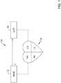
- FIG. 1is a schematic diagram showing an illustrative system 10 that may be used to sense and/or pace a heart H.
- the system 10may also be configured to be able to shock the heart H.
- the heart Hincludes a right atrium RA and a right ventricle RV.
- the heart Halso includes a left atrium LA and a left ventricle LV.
- the illustrative system 10includes an SICD (subcutaneous implantable cardioverter defibrillator) 12. While not shown in this Figure, in some cases the SICD 12 may include a lead that may be configured to be placed subcutaneously relative to a patient's sternum and outside of the patient's heart.
- SICDsubcutaneous implantable cardioverter defibrillator
- the leadmay extend around or through the sternum and may be fixed adjacent an inner surface of the sternum and outside of the patient's heart.
- the SICD 12may be configured to sense electrical activity generated by the heart H as well as provide electrical energy to the heart H in order to shock the heart H from an undesired heart rhythm to a desired heart rhythm.
- the system 10may include an LCP 14 that may be configured to sense and/or pace the heart H. While a single LCP 14 is illustrated, it will be appreciated that two or more LCPs 14 may be implanted in or on the heart H.
- the LCP 14may be implanted into any chamber of the heart, such as the right atrium RA, the left atrium LA, the right ventricle RV and the left ventricle LV. When more than one LCP is provided, each LCP may be implanted in a different chamber. In some cases, multiple LCP's may be implanted within a single chamber of the heart H.
- the SICD 12 and the LCP 14may be implanted at the same time. In some instances, depending on the cardiac deficiencies of a particular patient, the SICD 12 may be implanted first, and one or more LCPs 14 may be implanted at a later date if/when the patient's heart decompensates and it becomes necessary to pace the heart H. In some cases, it is contemplated that one or more LCPs 14 may be implanted first, in order to sense and pace the heart H. When a need for possible defibrillation becomes evident, the SICD 12 may subsequently be implanted. Regardless of implantation order or sequence, it will be appreciated that the SICD 12 and the LCP 14 may communicate with each other using any desired communications protocol, such as conducted communication through the patient's body.
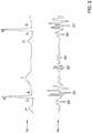
- the heart His controlled via electrical signals that pass through the cardiac tissue and that can be detected by implanted devices such as but not limited to the SICD 12 and/or the LCP 14 of Figure 1 .
- Figure 2includes a portion of an electrocardiogram (ECG) 16 along with a heart sounds trace 18.
- ECGelectrocardiogram
- a heartbeatincludes a P-wave that indicates atrial depolarization.
- a QRS complexincluding a Q-wave, an R-wave and an S-wave, represents ventricular depolarization.
- a T-waveindicates repolarization of the ventricles.
- the ECG 16may be detected by implanted devices such as but not limited to the SICD 12 and/or the LCP 14 of Figure 1 .
- a number of heart soundsmay also be detectable while the heart H beats. It will be appreciated that the heart sounds may be considered as on example of mechanical indications of the heart beating.
- Other illustrative mechanical indicationsmay include, for example, endocardial acceleration or movement of a heart wall detected by an accelerometer in the LCP, acceleration or movement of a heart wall detected by an accelerometer in the SICD, a pressure, pressure change, or pressure change rate in a chamber of the heart H detected by a pressure sensor of the LCP, acoustic signals caused by heart movements detected by an acoustic sensor (e.g. accelerometer, microphone, etc.) and/or any other suitable indication of a heart chamber beating.
- an acoustic sensore.g. accelerometer, microphone, etc.
- An electrical signaltypically instructs a portion of the heart H to contract, and then there is a corresponding mechanical indication.
- the heart soundsare a result of cardiac muscle contracting or relaxing in response to an electrical signal
- the electrical signalindicated by the ECG 16
- the corresponding mechanical indicationindicated in the example shown by the heart sounds trace 18.
- the P-wave of the ECG 16is an electrical signal triggering an atrial contraction.
- the S4 heart soundis the mechanical signal caused by the atrial contraction.
- a window following the P-wavecan be defined and searched in order to find and/or isolate the corresponding S4 heart sound.
- detection of both signalsmay be an indication of an increased confidence level in a detected atrial contraction.
- detection of either signalmay be sufficient to identify an atrial contraction.
- the identity of an atrial contractionmay be used to identify an atrial contraction timing fiducial (e.g. a timing marker of the atrial contraction).
- the relationship of certain electrical signals and/or mechanical indicationsmay be used to predict the timing of other electrical signals and/or mechanical indications within the same heartbeat.
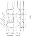
- the timing of certain electrical signals and/or mechanical indications corresponding to a particular heartbeatmay be used to predict the timing of other electrical signals and/or mechanical indications within a subsequent heartbeat. It will be appreciated that as the heart H undergoes a cardiac cycle, the blood pressures and blood volumes within the heart H will vary over time. Figure 3 illustrates how these parameters match up with the electrical signals and corresponding mechanical indications.
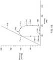
- Figure 3is a graph showing example pressures and volumes within a heart over time. More specifically, Figure 3 shows an illustrative example of the aortic pressure, left ventricular pressure, left atrial pressure, left ventricular volume, an electrocardiogram (ECG or egram), and heart sounds of the heart H over two consecutive heart beats.
- a cardiac cyclemay begin with diastole, and the mitral valve opens. The ventricular pressure falls below the atrial pressure, resulting in the ventricular filling with blood. During ventricular filling, the aortic pressure slowly decreases as shown. During systole, the ventricle contracts. When ventricular pressure exceeds the atrial pressure, the mitral valve closes, generating the S1 heart sound.
- an isovolumetric contraction phaseoccurs where the ventricle pressure rapidly increases but the ventricle volume does not significantly change.
- the aortic valveopens and the ejection phase begins where blood is ejected from the left ventricle into the aorta.
- the ejection phasecontinues until the ventricular pressure falls below the aortic pressure, at which point the aortic valve closes, generating the S2 heart sound.
- the isovolumetric relaxation phasebegins and ventricular pressure falls rapidly until it is exceeded by the atrial pressure, at which point the mitral valve opens and the cycle repeats.
- Cardiac pressure curves for the pulmonary artery, the right atrium, and the right ventricle, and the cardiac volume curve for the right ventricle,may be similar to those illustrated in Figure 3 . In many cases, the cardiac pressure in the right ventricle is lower than the cardiac pressure in the left ventricle.
- FIG. 4is a schematic diagram of an illustrative LCP 14.
- the LCP 14may be considered as being configured to sense cardiac activity and to pace a patient's heart H.
- the LCP 14may be disposable within a ventricle of the heart H, such as the right ventricle RV or the left ventricle LV.
- the LCP 14may be considered as including a housing 20, a first electrode 22 that is secured relative to the housing 20 and exposed to an environment outside the housing 20 (e.g. blood, tissue, etc.), and a second electrode 24 that is secured relative to the housing 20 and exposed to the environment outside of the housing 20 (e.g. blood, tissue, etc.).
- the second electrode 24may be spaced from the first electrode 22.
- the first electrode 22may be disposed at or near a first end 26 of the housing 20 and the second electrode 24 may be disposed at or near a second end 28 of the housing 20, although this is not required in all cases.
- the LCP 14may further include a controller 30 that is disposed within the housing 20 and that is operably coupled to the first electrode 22 via a first electrical connection 32 and the second electrode 24 via a second electrical connection 34.
- the controller 30may be capable of receiving, via the first electrode 22 and the second electrode 24, electrical signals that include an electrical indication of an atrial (or other) contraction (e.g. a P-wave of an ECG 16, see Figure 2 ).
- the controller 30may receive electrical signals (e.g. conducted communication signals) that include an indication of atrial (or other) contractions from a remote device such as the SICD 12 ( Figure 1 ).
- the controller 30may also be configured to determine an atrial contraction timing fiducial based at least in part upon a sensed indication of atrial contraction in a first heartbeat and/or a sensed indication of ventricular contraction in the first heartbeat, an immediately preceding heartbeat and/or an immediately succeeding heartbeat. In some cases, the controller 30 may be configured to generate and deliver a ventricle pacing pulse using the atrial contraction timing fiducial (e.g. after an A-V delay).
- the LCP 14may include an accelerometer 36 that is disposed within the housing 20 and that is operably coupled to the controller 30 via electrical connections 38. In some cases, as discussed further with respect to subsequent Figures, the LCP 14 may include an optional pressure sensor. In some cases, the controller 30 may be configured to detect, via a signal from the accelerometer 36, a mechanical indication of atrial (or other) contraction. In some cases, the mechanical indication of atrial contraction may include but is not limited to an S4 heart sound. While the LCP 14 is shown as including an accelerometer, it will be appreciated that other sensors may be able to provide a signal representing a mechanical indication of atrial (or other) contraction. For example, in some cases the LCP 14 may include a microphone.
- the LCP 14may include a sonomicrometer, a cardiomechanical sensor that includes, for example, embedded piezoelectric material, or other piezeoelectric sensors.
- the LCPmay include a pressure sensor for sensing an indication of atrial contraction.
- signals that provide an indication of atrial contractionmay include one or more of an S3 heart sound signal, an S4 heart sound signal, an A-wave signal and/or a P-wave signal.
- signals that provide an indication of ventricular contractionmay include one or more of a pulse pressure signal, a dP/dt signal, an R-wave to R-wave interval, a QRS complex width, and/or a ventricle pressure-volume loop parameter. These are just some examples.
- FIG. 5is a schematic diagram of an illustrative LCP 44.
- the LCP 44may be considered as being configured to sense cardiac activity and to pace a patient's heart H.
- the LCP 44may be disposable within a ventricle of the heart H, such as the right ventricle RV or the left ventricle LV.
- the LCP 44may be considered as including a housing 20, a first electrode 22 that is secured relative to the housing 20 and exposed to an environment outside the housing 20 (e.g. blood, tissue, etc.), and a second electrode 24 that is secured relative to the housing 20 and exposed to the environment outside of the housing 20 (e.g. blood, tissue, etc.).
- the second electrode 24may be spaced from the first electrode 22.
- the first electrode 22may be disposed at or near a first end 26 of the housing 20 and the second electrode 24 may be disposed at or near a second end 28 of the housing 20, although this is not required in all cases.
- the LCP 14may further include a controller 30 that is disposed within the housing 20 and that is operably coupled to the first electrode 22 via a first electrical connection 32 and the second electrode 24 via a second electrical connection 34.
- the controller 30may be capable of receiving, via the first electrode 22 and the second electrode 24, electrical signals that include an electrical indication of an atrial (or other) contraction (e.g. a P-wave of an ECG 16, see Figure 2 ).
- electrical signalsthat include an electrical indication of an atrial (or other) contraction (e.g. a P-wave of an ECG 16, see Figure 2 ).
- detecting a far-field P-wave via the electrodes 22 and 24 of an LCP implanted in the ventriclemay have a relatively low signal-to-noise ratio. Detecting the P-wave using the SICD lead may have a higher signal to noise ratio.
- the controller 30may receive electrical signals (e.g. conducted communication signals) that include an indication of atrial (or other) contractions from a remote device such as the SICD
- the LCP 44may include an accelerometer 36 that is disposed within the housing 20 and that is operably coupled to the controller 30 via electrical connections 38. In some cases, the LCP 44 may also include a pressure sensor 40 that is disposed within the housing 20 and that is operably coupled to the controller 30 via electrical connections 42. In some instances, a pressure sensor signal may be responsive to an atrial contraction of the patient's heart. Likewise an accelerometer signal may be responsive to an atrial contraction of the patient's heart.
- the pressure signalmay be used to determine a number of parameters.
- the pressure signalmay be used to determine or detect an A-wave (atrial kick).
- the pressure signalmay be used to determine or detect a pressure pulse or pressure vibrations associated with S4, which may, for example, be in the 25-30Hz range.
- the S4 heart soundmay be easier to detect using the pressure signal than the accelerometer signal, particularly since the ventricle pressure is not changing substantially at this time (ventricle is filling).
- the pressure signalmay be used to determine a change in ventricle pressure relative to time (dP/dt).
- the controller 30may be configured to detect, via a signal from the accelerometer 36, one or more signals indicating an atrial (or other) contraction.
- the signal received from the accelerometer 36may include a heart sound signal (e.g. S4) or an endocardial acceleration signal.
- the LCP 14is shown as including an accelerometer 36 and a pressure sensor 40, it will be appreciated that other sensors may also be able to provide a signal representing a mechanical indication of atrial (or other) contraction.
- the LCP 14may include a microphone.
- the LCP 44may include a sonomicrometer, a cardiomechanical sensor that includes, for example, embedded piezoelectric material, or other piezeoelectric sensors. These are just examples.
- the controller 30may also be configured determine an atrial contraction timing fiducial based at least in part upon two or more of a signal received from the pressure sensor 40, a signal received from the accelerometer 36 (e.g. representing a heart sound and/or endocardial acceleration), and an electrical cardiac signal received via the first electrode 22 and the second electrode 24.
- the electrical cardiac signal received via the first electrode 22 and the second electrode 24may include at least a portion of an electrocardiogram (ECG).
- ECGelectrocardiogram
- the electrical cardiac signal received via the first electrode 22 and the second electrode 24may include a P-wave.
- the electrical cardiac signal received via the first electrode 22 and the second electrode 24may include a QRS complex, from which a QRS width can be determined.
- the electrical cardiac signal received via the first electrode 22 and the second electrode 24may include two consecutive R waves, from which an R-wave to R-wave interval can be determined.
- the electrical cardiac signalmay include a conducted or other communicated electrical signal from another device (e.g. SICD device) that includes an indication of an atrial or other contraction of the heart H.
- the controller 30may be configured to generate and deliver a ventricle pacing pulse using the atrial contraction timing fiducial.
- the controller 30may be configured to determine the atrial contraction timing fiducial based at least in part upon a signal received from the pressure sensor 40 and a signal received from the accelerometer 36. In some instances, the controller 30 may be configured to determine the atrial contraction timing fiducial based at least in part upon a signal received from the pressure sensor 40 and an electrical cardiac signal received via the first electrode 22 and the second electrode 24. In some cases, the controller 30 may be configured to determine the atrial contraction timing fiducial based at least in part upon a sensed A-wave in the signal received from the pressure sensor 40 and a sensed signal associated with an S4 heart sound in the signal received from the accelerometer 36.
- the controller 30may be configured to determine a pace time for delivering a ventricle pacing pulse to the ventricle of the patient's heart H, and the controller 30 may determine the pace time based at least in part on a pressure signal received from the pressure sensor 40.
- the controllermay be configured to determine the pace time based at least in part on the received pressure signal and the received accelerometer signal.
- the controller 30may be configured to determine the pace time based at least in part on a heart sound or endocardial acceleration represented in the received pressure signal and/or in the received accelerometer signal.
- the controller 30may be configured to determine the pace time based at least in part on the received pressure signal and the received electrical cardiac signal. In some instances, the controller 30 may be configured to determine the pace time based at least in part on the received pressure signal, the received accelerometer signal and the received electrical cardiac signal. In some cases, the controller 30 may be configured to determine the pace time based at least in part on a diastolic pressure represented in the received pressure signal. In some cases, the controller 30 may be configured to determine the pace time based at least in part on an A-wave represented in the received pressure signal. In some instances, the controller 30 may be configured to determine the pace time based at least in part on a systolic pressure represented in the received pressure signal.
- the controller 30may be configured to determine the pace time based at least in part on a dP/dt parameter (e.g. pace at a time to maximize dP/dt in the ventricle) during systole represented in the received pressure signal. In some cases, the controller 30 may be configured to determine the pace time based at least in part on when the received pressure signal crossing a predetermined threshold during systole.
- a dP/dt parametere.g. pace at a time to maximize dP/dt in the ventricle
- the controller 30may be configured to determine the pace time based at least in part on an A-V delay relative to a previously determined atrial contraction timing fiducial, and the controller 30 may adjust the A-V delay based at least in part on one or more of the received pressure signal, the received accelerometer signal and the received electrical cardiac signal during the current, previous and/or subsequent cardiac cycles.
- the controller 30may be configured to determine a ventricle pace time for delivering a ventricle pacing pulse to the ventricle of the patient's heart H. For example, in some cases, the controller 30 may determine the ventricle pace time based at least in part on an indication of an atrial contraction event of the patient's heart H and an indication of a current posture of the patient. It will be appreciated that cardiac demand, or the blood pumping needs of the patient, may vary depending on whether the patient is laying down, sitting, standing, etc.
- an indication of an atrial contraction eventmay be based primarily or exclusively on the received accelerometer signal if the indication of the posture of the patient is reclined, and may be based primarily or exclusively on the received pressure signal if the indication of the posture of the patient is upright.
- the signal-to-noise ratiomay be greater for the accelerometer signal when the patient is at rest (e.g. reclined) and the signal-to-noise ratio may be greater for the pressure signal when the patient is active (e.g. upright).
- the controller 30may be configured to determine the indication of the posture of the patient based at least in part on the accelerometer signal.
- the controller 30may be configured to determine the ventricle pace time based at least in part on an LV pressure parameter indicated in the pressure sensor signal when the indication of the posture of the patient is upright.
- the controller 30may, conversely, be configured to determine the ventricle pace time based at least in part on a heart sound indicated in the pressure sensor signal and/or in the accelerometer signal when the indication of the posture of the patient is reclined.
- the controller 30may be configured to determine the ventricle pace time to achieve lower passive ventricular filling when the indication of the posture of the patient is upright and to determine the ventricle pace time to achieve higher passive ventricular filling when the indication of the posture of the patient is reclined (e.g.
- Thismay operate the heart in a manner that reduces stretch stress on the heart while still meeting the current metabolic demands of the patient during times when the metabolic demand is relative low (e.g. reclined), and to operate the heart in a manner that maximizes pumping capacity when the metabolic demand is higher (e.g. upright). This may help reduce the rate at which a patient's heart decompensates by allowing the heart to "rest" more during times of low metabolic demand.
- metabolic demandmay be estimated based on any number of other parameters including, for example, heart rate, respiration of the patient, activity level of the patient, posture, blood gas, blood analytes (e.g. lactate or norepinephrine), cardiac conduction velocities (e.g. PR interval or QT interval) and/or sleep state.
- heart raterespiration of the patient
- activity level of the patientposture
- blood gasblood analytes (e.g. lactate or norepinephrine)
- cardiac conduction velocitiese.g. PR interval or QT interval
- sleep statee.g. PR interval or QT interval
- FIG. 6is a schematic diagram of an illustrative LCP 54.
- the LCP 54may be considered as being configured to sense cardiac activity and to pace a patient's heart H.
- the LCP 54may be disposable within a ventricle of the heart H, such as the right ventricle RV or the left ventricle LV.
- the LCP 54may be considered as including a housing 20, a first electrode 22 that is secured relative to the housing 20 and exposed to an environment outside the housing 20 (e.g. blood, tissue, etc.), and a second electrode 24 that is secured relative to the housing 20 and exposed to the environment outside of the housing 20 (e.g. blood, tissue, etc.).
- the second electrode 24may be spaced from the first electrode 22.
- the first electrode 22may be disposed at or near a first end 26 of the housing 20 and the second electrode 24 may be disposed at or near a second end 28 of the housing 20, although this is not required in all cases.
- the LCP 54may further include a controller 30 that is disposed within the housing 20 and that is operably coupled to the first electrode 22 via a first electrical connection 32 and the second electrode 24 via a second electrical connection 34.
- the controller 30may be capable of receiving, via the first electrode 22 and the second electrode 24, electrical signals representative of cardiac activity.
- the controller 30may receive signals that include an electrical indication of an atrial (or other) contraction (e.g. a P-wave of an ECG 16, see Figure 2 ).
- the controller 30may receive electrical signals (e.g. conducted communication signals) that include an indication of atrial (or other) contractions from a remote device such as the SICD 12 ( Figure 1 ).
- the LCP 54may include a memory 56 that is operably coupled to the controller 30 via electrical connections 58.
- the memory 56may be configured to store information pertaining to a previously determined atrial contraction timing fiducial, as well as other information.
- the LCP 54may include an accelerometer 36 that is disposed within the housing 20 and that is operably coupled to the controller 30 via electrical connections 38. In some cases, the LCP 54 may further include a pressure sensor 40 that is disposed within the housing 20 and that is operably coupled to the controller 30 via electrical connections 42.
- the controller 30may, for example, be configured to receive an accelerometer signal from the accelerometer 36 and/or a pressure sensor signal from the pressure sensor 40. In some instances, for example, the controller 30 may be configured to determine an A-V delay relative to a previously determined atrial contraction timing fiducial based at least in part on a pressure signal from the pressure sensor 40. In some cases, the controller 30 may be configured to adjust the A-V delay based at least in part on the accelerometer signal. In some cases, the controller 30 may be configured to generate a ventricle pacing pulse after the adjusted A-V delay following the previously determined atrial contraction timing fiducial.
- the pressure signal received by the controller 30may include a pulse pressure, and the controller 30 may be configured to adjust the A-V delay relative to the previously determined atrial contraction timing fiducial based at least in part on the pulse pressure.
- the pressure signal received by the controller 30includes a rate of change in pressure over time (dP/dt) and the controller 30 may be configured to adjust the A-V delay relative to the previously determined atrial contraction timing fiducial based at least in part on the dP/dt.
- the A-V delaymay be adjusted to maximize the dP/dt sensed in the ventricle.
- the A-V delaymay be adjusted to minimize the negative dP/dt sensed in the ventricle in diastole.
- the A-V delaymay be adjusted to achieve a minimum ventricle pressure pulse width (e.g. width between maximum dP/dt and maximum negative dP/dt).
- heart sounds in conjunction with the LV pressure waveformmay be used to separate out various timing components of the heart H such as ejection time, isovolumetric contraction time, isovolumetric relation time, etc.
- the pressure signal received by the controller 30may include an A-wave signal
- the controller 30may be configured to progressively reduce the A-V delay until the A-wave signal is not detected, and then progressively increase the A-V delay until the A-wave signal is again just detected and an onset of LV pressure rise is right on top of the A-wave, at which point the A-V delay may be considered to be optimal.
- the controller 30may be configured to adjust the A-V delay in response to an LV volume related impedance signal received or measured via the first electrode 22 and the second electrode 24, and the controller 30 may adjust the A-V delay relative to the previously determined atrial contraction timing fiducial in order to increase an LV ejection fraction that is estimated using the LV volume related impedance signal.
- the controller 30may be configured to adjust the A-V delay in response to an electrical cardiac signal received via the first electrode 22 and the second electrode 24 including a QRS complex, from which a QRS width can be determined, and the controller 30 may be configured to adjust the A-V delay relative to the previously determined atrial contraction timing fiducial in order to minimize the QRS width.
- the controller 30may be configured to adjust the A-V delay in response to a received signal indicative of mitral regurgitation from the pressure sensor 40 and/or the accelerometer 36, and the controller 30 may be configured to adjust the A-V delay relative to the previously determined atrial contraction timing fiducial in order to minimize detected mitral regurgitation.
- FIG. 7is a schematic diagram of an illustrative LCP 64.
- the LCP 64may be considered as being configured to sense cardiac activity and to pace a patient's heart H.
- the LCP 64may be disposable within a ventricle of the heart H, such as the right ventricle RV or the left ventricle LV.
- the LCP 64may be considered as including a housing 20, a first electrode 22 that is secured relative to the housing 20 and exposed to an environment outside the housing 20 (e.g. blood, tissue, etc.), and a second electrode 24 that is secured relative to the housing 20 and exposed to the environment outside of the housing 20 (e.g. blood, tissue, etc.).
- the second electrode 24may be spaced from the first electrode 22.
- the first electrode 22may be disposed at or near a first end 26 of the housing 20 and the second electrode 24 may be disposed at or near a second end 28 of the housing 20, although this is not required in all cases.
- the LCP 64may further include a controller 30 that is disposed within the housing 20 and that is operably coupled to the first electrode 22 via a first electrical connection 32 and the second electrode 24 via a second electrical connection 34.
- the controller 30may be capable of receiving, via the first electrode 22 and the second electrode 24, electrical signals representative of cardiac activity.
- the controller 30may receive signals that include an electrical indication of an atrial (or other) contraction (e.g. a P-wave of an ECG 16, see Figure 2 ).
- the controller 30may receive electrical signals (e.g. conducted communication signals) that include an indication of atrial (or other) contractions from a remote device such as the SICD 12 ( Figure 1 ).
- the LCP 64may include a first sensor 66 and a second sensor 68.
- the first sensor 66may be disposed within the housing 20 and may be operably coupled to the controller 30 via electrical connections 70.
- the second sensor 68may be disposed within the housing 20 and may be operably coupled to the controller 30 via electrical connections 72.
- the first sensor 66may include an accelerometer.
- the second sensor 68may include a pressure sensor.
- the first sensor 66may provide a first sensor signal to the controller 30, where the first sensor signal is responsive to an atrial contraction of the patient' heart.
- the second sensor 68may provide a second sensor signal to the controller 30, where the second sensor signal is responsive to an atrial contraction of the patient's heart.
- a signal from the first sensor 66may be weighted with a first weight and a signal from the second sensor 68 may be weighted with a second weight.
- the first weight applied to the first signal and/or the second weight applied to the second signalmay be based at least in part on a confidence level in the corresponding signals.
- the weightsmay be based at least in part on the Signal-To-Noise ratio (SNR) of the corresponding signals.
- the controller 30may, for example, preferentially rely more on the first signal from the first sensor 66 and less on the second signal from the second sensor 68. In some instances, the controller 30 may preferentially rely more on the second signal from the second sensor 68 and less on the first signal from the first sensor 66.
- the controller 30may be configured to determine a ventricle pace time for delivering a ventricle pacing pulse to the ventricle of the patient's heart. In some cases, the controller 30 may determine the ventricle pace time based at least in part on an indication of an atrial contraction event of the patient's heart, and in some cases an indication of metabolic demand on the patient's heart.
- the indication of an atrial contraction eventmay be based primarily or exclusively on the received first signal if the indication of metabolic demand is below a metabolic demand threshold and may be based primarily or exclusively on the received second signal if the indication of metabolic demand is above the metabolic demand threshold. In some cases, the indication of metabolic demand may be based at least in part upon the received first sensor signal.
- the indication of metabolic demandmay be based at least in part upon the received second sensor signal. In some instances, the indication of metabolic demand may be based at least in part upon the received electrical cardiac signal.
- the controller 30may be configured to generate a ventricle pacing pulse at the ventricle pace time.
- either the first sensor 66 or the second sensor 68may be an accelerometer, and the controller 30 may be configured to determine a posture of the patient based at least in part on an accelerometer signal from the accelerometer, and may determine an indication of metabolic demand based at least in part on the determined posture.
- either the first sensor 66 or the second sensor 68may be an accelerometer, and the controller 30 may be configured to determine an activity level of the patient based at least in part on an accelerometer signal from the accelerometer, and to determine the indication of metabolic demand based at least in part on the determined activity level.
- the first sensor 66 and the second sensor 68may include an accelerometer and a pressure sensor, and the controller 30 may be configured to attempt to detect an A-wave via a pressure signal from the pressure sensor.
- the controller 30may also determine a ventricle pace time based at least in part on: (1) the A-wave when the A-wave is detected; and (2) one or more of a received pressure signal from the pressure sensor and/or a received accelerometer signal from the accelerometer other than the A-wave when the A-wave is not detected.
- the controller 30may be configured to determine a ventricle pace time based at least in part on an LV pressure parameter indicated in a pressure signal of the pressure sensor when the indication of metabolic demand is above the metabolic demand threshold and to determine the ventricle pace time based at least in part on a heart sound indicated in the pressure signal of the pressure sensor and/or in an accelerometer signal of the accelerometer when the indication of metabolic demand is below the metabolic demand threshold.
- the controller 30may be configured to detect an S2 heart sound via the pressure sensor and/or the accelerometer and detect an A-wave via the pressure sensor. In some cases, the controller 30 may be configured to determine a ventricle pace time to achieve a smaller S2 to A-wave interval when the indication of metabolic demand exceeds a relaxation threshold and to achieve a larger S2 to A-wave interval when the indication of metabolic demand does not exceed the relaxation threshold. In some cases, the controller 30 may be configured to detect an S2 heart sound via the pressure sensor and/or the accelerometer and to detect an S1 heart sound via the pressure sensor and/or the accelerometer.
- the controller 30may be configured to determine a ventricle pace time to achieve a smaller S2 to S1 interval when the indication of metabolic demand exceeds a relaxation threshold and to determine the ventricle pace time to achieve a larger S2 to S1 interval when the indication of metabolic demand does not exceed the relaxation threshold.
- the relaxation thresholdis set to correspond to when the patient is in a relaxation (versus active) state.
- either the first sensor 66 or the second sensor 68may include a pressure sensor, and the controller 30 may be configured to determine a ventricle pace time to achieve a higher change rate in LV pressure over time (dP/dt) when the indication of metabolic demand is above a relaxation threshold, and to determine a ventricle pace time to achieve a lower change rate in LV pressure over time (dP/dt) when the indication of metabolic demand is below the relaxation threshold.
- the controller 30may be configured to determine a ventricle pace time to achieve lower passive ventricular filling when the indication of metabolic demand is above a relaxation threshold, and to determine a ventricle pace time to achieve higher passive ventricular filling when the indication of metabolic demand is below a relaxation threshold.
- the above-referenced relaxation thresholdmay not be a single threshold.
- the relaxation thresholdmay include hysteresis, where a different relaxation threshold is applied depending on whether the patient is transitioning from a relaxed state to an active state, or from an active state to a relaxed state.
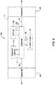
- FIG 8depicts another illustrative leadless cardiac pacemaker (LCP) that may be implanted into a patient and may operate to deliver appropriate therapy to the heart, such as to deliver anti-tachycardia pacing (ATP) therapy, cardiac resynchronization therapy (CRT), bradycardia therapy, and/or the like.
- the LCP 100may be a compact device with all components housed within the or directly on a housing 120.
- the LCP 100may be considered as being an example of one or more of the LCP 14 ( Figures 1 and 3 ), the LCP 44 ( Figure 5 ), the LCP 54 ( Figure 6 ) and/or the LCP 64 ( Figure 7 ).
- the LCP 100may include a communication module 102, a pulse generator module 104, an electrical sensing module 106, a mechanical sensing module 108, a processing module 110, a battery 112, and an electrode arrangement 114.
- the LCP 100may include more or less modules, depending on the application.
- the communication module 102may be configured to communicate with devices such as sensors, other medical devices such as an SICD, and/or the like, that are located externally to the LCP 100. Such devices may be located either external or internal to the patient's body. Irrespective of the location, external devices (i.e. external to the LCP 100 but not necessarily external to the patient's body) can communicate with the LCP 100 via communication module 102 to accomplish one or more desired functions. For example, the LCP 100 may communicate information, such as sensed electrical signals, data, instructions, messages, R-wave detection markers, etc., to an external medical device through the communication module 102.
- informationsuch as sensed electrical signals, data, instructions, messages, R-wave detection markers, etc.
- the external medical devicemay use the communicated signals, data, instructions, messages, R-wave detection markers, etc., to perform various functions, such as determining occurrences of arrhythmias, delivering electrical stimulation therapy, storing received data, and/or performing any other suitable function.
- the LCP 100may additionally receive information such as signals, data, instructions and/or messages from the external medical device through the communication module 102, and the LCP 100 may use the received signals, data, instructions and/or messages to perform various functions, such as determining occurrences of arrhythmias, delivering electrical stimulation therapy, storing received data, and/or performing any other suitable function.
- the communication module 102may be configured to use one or more methods for communicating with external devices. For example, the communication module 102 may communicate via radiofrequency (RF) signals, inductive coupling, optical signals, acoustic signals, conducted communication signals, and/or any other signals suitable for communication.
- RFradiofrequency
- the pulse generator module 104may be electrically connected to the electrodes 114.
- the LCP 100may additionally include electrodes 114'.
- the pulse generator 104may also be electrically connected to the electrodes 114'.
- the pulse generator module 104may be configured to generate electrical stimulation signals.
- the pulse generator module 104may generate and deliver electrical stimulation signals by using energy stored in the battery 112 within the LCP 100 and deliver the generated electrical stimulation signals via the electrodes 114 and/or 114'.
- the pulse generator 104may include one or more capacitors, and the pulse generator 104 may charge the one or more capacitors by drawing energy from the battery 112.
- the pulse generator 104may then use the energy of the one or more capacitors to deliver the generated electrical stimulation signals via the electrodes 114 and/or 114'.
- the pulse generator 104 of the LCP 100may include switching circuitry to selectively connect one or more of the electrodes 114 and/or 114' to the pulse generator 104 in order to select which of the electrodes 114/114' (and/or other electrodes) the pulse generator 104 delivers the electrical stimulation therapy.
- the pulse generator module 104may generate and deliver electrical stimulation signals with particular features or in particular sequences in order to provide one or multiple of a number of different stimulation therapies.
- the pulse generator module 104may be configured to generate electrical stimulation signals to provide electrical stimulation therapy to combat bradycardia, tachycardia, cardiac synchronization, bradycardia arrhythmias, tachycardia arrhythmias, fibrillation arrhythmias, cardiac synchronization arrhythmias and/or to produce any other suitable electrical stimulation therapy.
- Some more common electrical stimulation therapiesinclude anti-tachycardia pacing (ATP) therapy, cardiac resynchronization therapy (CRT), and cardioversion/defibrillation therapy.
- the LCP 100may not include a pulse generator 104.
- the LCP 100may be a diagnostic only device.
- the LCP 100may not deliver electrical stimulation therapy to a patient. Rather, the LCP 100 may collect data about cardiac electrical activity and/or physiological parameters of the patient and communicate such data and/or determinations to one or more other medical devices via the communication module 102.
- the LCP 100may include an electrical sensing module 106, and in some cases, a mechanical sensing module 108.
- the electrical sensing module 106may be configured to sense the cardiac electrical activity of the heart.
- the electrical sensing module 106may be connected to the electrodes 114/114', and the electrical sensing module 106 may be configured to receive cardiac electrical signals conducted through the electrodes 114/114'.
- the cardiac electrical signalsmay represent local information from the chamber in which the LCP 100 is implanted. For instance, if the LCP 100 is implanted within a ventricle of the heart (e.g. RV, LV), cardiac electrical signals sensed by the LCP 100 through the electrodes 114/114' may represent ventricular cardiac electrical signals.
- the LCP 100may be configured to detect cardiac electrical signals from other chambers (e.g. far field), such as the P-wave from the atrium.
- the mechanical sensing module 108may include one or more sensors, such as an accelerometer, a pressure sensor, a heart sound sensor, a blood-oxygen sensor, a chemical sensor, a temperature sensor, a flow sensor and/or any other suitable sensors that are configured to measure one or more mechanical/chemical parameters of the patient. Both the electrical sensing module 106 and the mechanical sensing module 108 may be connected to a processing module 110, which may provide signals representative of the sensed mechanical parameters. Although described with respect to Figure 8 as separate sensing modules, in some cases, the electrical sensing module 206 and the mechanical sensing module 208 may be combined into a single sensing module, as desired.
- the electrodes 114/114'can be secured relative to the housing 120 but exposed to the tissue and/or blood surrounding the LCP 100.
- the electrodes 114may be generally disposed on either end of the LCP 100 and may be in electrical communication with one or more of the modules 102, 104, 106, 108, and 110.
- the electrodes 114/114'may be supported by the housing 120, although in some examples, the electrodes 114/114' may be connected to the housing 120 through short connecting wires such that the electrodes 114/114' are not directly secured relative to the housing 120.
- the electrodes 114'may in some cases be disposed on the sides of the LCP 100, which may increase the number of electrodes by which the LCP 100 may sense cardiac electrical activity, deliver electrical stimulation and/or communicate with an external medical device.
- the electrodes 114/114'can be made up of one or more biocompatible conductive materials such as various metals or alloys that are known to be safe for implantation within a human body.
- the electrodes 114/114' connected to the LCP 100may have an insulative portion that electrically isolates the electrodes 114/114' from adjacent electrodes, the housing 120, and/or other parts of the LCP 100.
- one or more of the electrodes 114/114'may be provided on a tail (not shown) that extends away from the housing 120.
- the processing module 110can be configured to control the operation of the LCP 100.
- the processing module 110may be configured to receive electrical signals from the electrical sensing module 106 and/or the mechanical sensing module 108. Based on the received signals, the processing module 110 may determine, for example, abnormalities in the operation of the heart H. Based on any determined abnormalities, the processing module 110 may control the pulse generator module 104 to generate and deliver electrical stimulation in accordance with one or more therapies to treat the determined abnormalities.
- the processing module 110may further receive information from the communication module 102. In some examples, the processing module 110 may use such received information to help determine whether an abnormality is occurring, determine a type of abnormality, and/or to take particular action in response to the information.
- the processing module 110may additionally control the communication module 102 to send/receive information to/from other devices.
- the processing module 110may include a pre-programmed chip, such as a very-large-scale integration (VLSI) chip and/or an application specific integrated circuit (ASIC).
- the chipmay be pre-programmed with control logic in order to control the operation of the LCP 100.
- the processing module 110may use less power than other programmable circuits (e.g. general purpose programmable microprocessors) while still being able to maintain basic functionality, thereby potentially increasing the battery life of the LCP 100.
- the processing module 110may include a programmable microprocessor.
- Such a programmable microprocessormay allow a user to modify the control logic of the LCP 100 even after implantation, thereby allowing for greater flexibility of the LCP 100 than when using a pre-programmed ASIC.
- the processing module 110may further include a memory, and the processing module 110 may store information on and read information from the memory.
- the LCP 100may include a separate memory (not shown) that is in communication with the processing module 110, such that the processing module 110 may read and write information to and from the separate memory.
- the battery 112may provide power to the LCP 100 for its operations.
- the battery 112may be a non-rechargeable lithium-based battery.
- a non-rechargeable batterymay be made from other suitable materials, as desired.
- the LCP 100is an implantable device, access to the LCP 100 may be limited after implantation. Accordingly, it is desirable to have sufficient battery capacity to deliver therapy over a period of treatment such as days, weeks, months, years or even decades.
- the battery 112may a rechargeable battery, which may help increase the useable lifespan of the LCP 100.
- the battery 110may be some other type of power source, as desired.
- the LCP 100may include one or more anchors 116.
- the anchor 116may include any one of a number of fixation or anchoring mechanisms.
- the anchor 116may include one or more pins, staples, threads, screws, helix, tines, and/or the like.
- the anchor 116may include threads on its external surface that may run along at least a partial length of the anchor 116. The threads may provide friction between the cardiac tissue and the anchor to help fix the anchor 116 within the cardiac tissue.
- the anchor 116may include other structures such as barbs, spikes, or the like to facilitate engagement with the surrounding cardiac tissue.
- Figure 9depicts an example of another medical device (MD) 200, which may be used in conjunction with the LCP 100 ( Figure 8 ) in order to detect and/or treat cardiac abnormalities.
- the MD 200may be considered as an example of the SICD 12 ( Figure 1 ).
- the MD 200may include a communication module 202, a pulse generator module 204, an electrical sensing module 206, a mechanical sensing module 208, a processing module 210, and a battery 218. Each of these modules may be similar to the modules 102, 104, 106, 108, and 110 of LCP 100.
- the battery 218may be similar to the battery 112 of the LCP 100.
- the MD 200may have a larger volume within the housing 220.
- the MD 200may include a larger battery and/or a larger processing module 210 capable of handling more complex operations than the processing module 110 of the LCP 100.
- the MD 200may be another leadless device such as shown in Figure 8
- the MD 200may include leads such as leads 212.
- the leads 212may include electrical wires that conduct electrical signals between the electrodes 214 and one or more modules located within the housing 220. In some cases, the leads 212 may be connected to and extend away from the housing 220 of the MD 200. In some examples, the leads 212 are implanted on, within, or adjacent to a heart of a patient.
- the leads 212may contain one or more electrodes 214 positioned at various locations on the leads 212, and in some cases at various distances from the housing 220. Some leads 212 may only include a single electrode 214, while other leads 212 may include multiple electrodes 214.
- the electrodes 214are positioned on the leads 212 such that when the leads 212 are implanted within the patient, one or more of the electrodes 214 are positioned to perform a desired function.
- the one or more of the electrodes 214may be in contact with the patient's cardiac tissue.
- the one or more of the electrodes 214may be positioned subcutaneously and outside of the patient's heart.
- the electrodes 214may conduct intrinsically generated electrical signals to the leads 212, e.g. signals representative of intrinsic cardiac electrical activity.
- the leads 212may, in turn, conduct the received electrical signals to one or more of the modules 202, 204, 206, and 208 of the MD 200.
- the MD 200may generate electrical stimulation signals, and the leads 212 may conduct the generated electrical stimulation signals to the electrodes 214.
- the electrodes 214may then conduct the electrical signals and delivery the signals to the patient's heart (either directly or indirectly).
- the mechanical sensing module 208may contain or be electrically connected to one or more sensors, such as accelerometers, acoustic sensors, blood pressure sensors, heart sound sensors, blood-oxygen sensors, and/or other sensors which are configured to measure one or more mechanical/chemical parameters of the heart and/or patient.
- sensorssuch as accelerometers, acoustic sensors, blood pressure sensors, heart sound sensors, blood-oxygen sensors, and/or other sensors which are configured to measure one or more mechanical/chemical parameters of the heart and/or patient.
- one or more of the sensorsmay be located on the leads 212, but this is not required.
- one or more of the sensorsmay be located in the housing 220.
- the MD 200may be an implantable medical device.
- the housing 220 of the MD 200may be implanted in, for example, a transthoracic region of the patient.
- the housing 220may generally include any of a number of known materials that are safe for implantation in a human body and may, when implanted, hermetically seal the various components of the MD 200 from fluids and tissues of the patient's body.
- the MD 200may be an implantable cardiac pacemaker (ICP).
- the MD 200may have one or more leads, for example the leads 212, which are implanted on or within the patient's heart.
- the one or more leads 212may include one or more electrodes 214 that are in contact with cardiac tissue and/or blood of the patient's heart.
- the MD 200may be configured to sense intrinsically generated cardiac electrical signals and determine, for example, one or more cardiac arrhythmias based on analysis of the sensed signals.
- the MD 200may be configured to deliver CRT, ATP therapy, bradycardia therapy, and/or other therapy types via the leads 212 implanted within the heart.
- the MD 200may additionally be configured provide defibrillation therapy.
- the MD 200may be an implantable cardioverter-defibrillator (ICD).
- the MD 200may include one or more leads implanted within a patient's heart.
- the MD 200may also be configured to sense cardiac electrical signals, determine occurrences of tachyarrhythmias based on the sensed signals, and may be configured to deliver defibrillation therapy in response to determining an occurrence of a tachyarrhythmia.
- the MD 200may be a subcutaneous implantable cardioverter-defibrillator (S-ICD).
- S-ICDsubcutaneous implantable cardioverter-defibrillator
- one of the leads 212may be a subcutaneously implanted lead.
- the MD 200may include only a single lead which is implanted subcutaneously, but this is not required.
- the lead(s)may have one or more electrodes that are placed subcutaneously and outside of the chest cavity.
- the lead(s)may have one or more electrodes that are placed inside of the chest cavity, such as just interior of the sternum.
- the MD 200may not be an implantable medical device. Rather, the MD 200 may be a device external to the patient's body, and may include skin-electrodes that are placed on a patient's body. In such examples, the MD 200 may be able to sense surface electrical signals (e.g. cardiac electrical signals that are generated by the heart or electrical signals generated by a device implanted within a patient's body and conducted through the body to the skin). In such examples, the MD 200 may be configured to deliver various types of electrical stimulation therapy, including, for example, defibrillation therapy.
- surface electrical signalse.g. cardiac electrical signals that are generated by the heart or electrical signals generated by a device implanted within a patient's body and conducted through the body to the skin.
- the MD 200may be configured to deliver various types of electrical stimulation therapy, including, for example, defibrillation therapy.
- Figure 10illustrates an example of a medical device system and a communication pathway through which multiple medical devices 302, 304, 306, and/or 310 may communicate.
- the medical device system 300may include LCPs 302 and 304, external medical device 306, and other sensors/devices 310.
- the external device 306may be any of the devices described previously with respect to the MD 200.
- Other sensors/devices 310may also be any of the devices described previously with respect to the MD 200.
- other sensors/devices 310may include a sensor, such as an accelerometer, an acoustic sensor, a blood pressure sensor, or the like.
- other sensors/devices 310may include an external programmer device that may be used to program one or more devices of the system 300.
- the LCPs 302 and/or 304may sense intrinsic cardiac electrical signals and may communicate such signals to one or more other devices 302/304, 306, and 310 of the system 300 via communication pathway 308.
- one or more of the devices 302/304may receive such signals and, based on the received signals, determine an occurrence of an arrhythmia.
- the device or devices 302/304may communicate such determinations to one or more other devices 306 and 310 of the system 300.
- one or more of the devices 302/304, 306, and 310 of the system 300may take action based on the communicated determination of an arrhythmia, such as by delivering a suitable electrical stimulation to the heart of the patient.
- the communication pathway 308may communicate using RF signals, inductive coupling, optical signals, acoustic signals, or any other signals suitable for communication. Additionally, in at least some examples, device communication pathway 308 may include multiple signal types. For instance, other sensors/device 310 may communicate with the external device 306 using a first signal type (e.g. RF communication) but communicate with the LCPs 302/304 using a second signal type (e.g. conducted communication). Further, in some examples, communication between devices may be limited.
- a first signal typee.g. RF communication
- a second signal typee.g. conducted communication
- the LCPs 302/304may communicate with the external device 306 only through other sensors/devices 310, where the LCPs 302/304 send signals to other sensors/devices 310, and other sensors/devices 310 relay the received signals to the external device 306.
- the communication pathway 308may include conducted communication.
- devices of the system 300may have components that allow for such conducted communication.
- the devices of system 300may be configured to transmit conducted communication signals (e.g. current and/or voltage pulses) into the patient's body via one or more electrodes of a transmitting device, and may receive the conducted communication signals (e.g. pulses) via one or more electrodes of a receiving device.
- the patient's bodymay "conduct" the conducted communication signals (e.g. pulses) from the one or more electrodes of the transmitting device to the electrodes of the receiving device in the system 300.
- the delivered conducted communication signals(e.g. pulses) may differ from pacing or other therapy signals.
- the devices of the system 300may deliver electrical communication pulses at an amplitude /pulse width that is sub-threshold to the heart.
- the amplitude/pulse width of the delivered electrical communication pulsesmay be above the capture threshold of the heart, but may be delivered during a blanking period of the heart and/or may be incorporated in or modulated onto a pacing pulse, if desired.
- Delivered electrical communication pulsesmay be modulated in any suitable manner to encode communicated information.
- the communication pulsesmay be pulse width modulated or amplitude modulated.
- the time between pulsesmay be modulated to encode desired information.
- conducted communication pulsesmay be voltage pulses, current pulses, biphasic voltage pulses, biphasic current pulses, or any other suitable electrical pulse as desired.
- FIG 11shows an illustrative medical device systems.
- an LCP 402is shown fixed to the interior of the left ventricle of the heart 410, and a pulse generator 406 is shown coupled to a lead 412 having one or more electrodes 408a-408c.
- the pulse generator 406may be part of a subcutaneous implantable cardioverter-defibrillator (S-ICD), and the one or more electrodes 408a-408c may be positioned subcutaneously.
- the one or more electrodes 408a-408cmay be placed inside of the chest cavity but outside of the heart, such as just interior of the sternum.
- the LCP 402may communicate with the subcutaneous implantable cardioverter-defibrillator (S-ICD).
- the lead 412may include an accelerometer 414 that may, for example, be configured to sense vibrations that may be indicative of heart sounds.
- the LCP 402may be in the right ventricle, right atrium, left ventricle or left atrium of the heart, as desired. In some cases, more than one LCP 402 may be implanted. For example, one LCP may be implanted in the right ventricle and another may be implanted in the right atrium. In another example, one LCP may be implanted in the right ventricle and another may be implanted in the left ventricle. In yet another example, one LCP may be implanted in each of the chambers of the heart.
- an LCPWhen an LCP is placed in, for example, the left ventricle, and no LCP is placed in the left atrium, techniques of the present disclosure may be used to help determine an atrial contraction timing fiducial for the left atrium. This atrial contraction timing fiducial may then be used to determine a proper time to pace the left ventricle via the LCP, such as an AV delay after the atrial contraction timing fiducial.
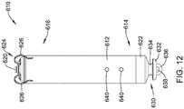
- FIG 12is a side view of an illustrative implantable leadless cardiac pacemaker (LCP) 610.
- the LCP 610may be similar in form and function to the LCP 100 described above.
- the LCP 610may include any of the modules and/or structural features described above with respect to the LCP 100 described above.
- the LCP 610may include a shell or housing 612 having a proximal end 614 and a distal end 616.
- the illustrative LCP 610includes a first electrode 620 secured relative to the housing 612 and positioned adjacent to the distal end 616 of the housing 612 and a second electrode 622 secured relative to the housing 612 and positioned adjacent to the proximal end 614 of the housing 612.
- the housing 612may include a conductive material and may be insulated along a portion of its length. A section along the proximal end 614 may be free of insulation so as to define the second electrode 622.
- the electrodes 620, 622may be sensing and/or pacing electrodes to provide electro-therapy and/or sensing capabilities.
- the first electrode 620may be capable of being positioned against or may otherwise contact the cardiac tissue of the heart while the second electrode 622 may be spaced away from the first electrode 620.
- the first and/or second electrodes 620, 622may be exposed to the environment outside the housing 612 (e.g. to blood and/or tissue).
- the LCP 610may include a pulse generator (e.g., electrical circuitry) and a power source (e.g., a battery) within the housing 612 to provide electrical signals to the electrodes 620, 622 to control the pacing/sensing electrodes 620, 622. While not explicitly shown, the LCP 610 may also include, a communications module, an electrical sensing module, a mechanical sensing module, and/or a processing module, and the associated circuitry, similar in form and function to the modules 102, 106, 108, 110 described above. The various modules and electrical circuitry may be disposed within the housing 612. Electrical communication between the pulse generator and the electrodes 620, 622 may provide electrical stimulation to heart tissue and/or sense a physiological condition.
- a pulse generatore.g., electrical circuitry
- a power sourcee.g., a battery
- the LCP 610includes a fixation mechanism 624 proximate the distal end 616 of the housing 612.
- the fixation mechanism 624is configured to attach the LCP 610 to a wall of the heart H, or otherwise anchor the LCP 610 to the anatomy of the patient.
- the fixation mechanism 624may include one or more, or a plurality of hooks or tines 626 anchored into the cardiac tissue of the heart H to attach the LCP 610 to a tissue wall.
- the fixation mechanism 624may include one or more, or a plurality of passive tines, configured to entangle with trabeculae within the chamber of the heart H and/or a helical fixation anchor configured to be screwed into a tissue wall to anchor the LCP 610 to the heart H.
- the LCP 610may further include a docking member 630 proximate the proximal end 614 of the housing 612.
- the docking member 630may be configured to facilitate delivery and/or retrieval of the LCP 610.
- the docking member 630may extend from the proximal end 614 of the housing 612 along a longitudinal axis of the housing 612.
- the docking member 630may include a head portion 632 and a neck portion 634 extending between the housing 612 and the head portion 632.
- the head portion 632may be an enlarged portion relative to the neck portion 634.
- the head portion 632may have a radial dimension from the longitudinal axis of the LCP 610 that is greater than a radial dimension of the neck portion 634 from the longitudinal axis of the LCP 610.
- the docking member 630may further include a tether retention structure 636 extending from or recessed within the head portion 632.
- the tether retention structure 636may define an opening 638 configured to receive a tether or other anchoring mechanism therethrough. While the retention structure 636 is shown as having a generally "U-shaped" configuration, the retention structure 636 may take any shape that provides an enclosed perimeter surrounding the opening 638 such that a tether may be securably and releasably passed (e.g.
- the docking member 630may be configured to facilitate delivery of the LCP 610 to the intracardiac site and/or retrieval of the LCP 610 from the intracardiac site. While this describes one example docking member 630, it is contemplated that the docking member 630, when provided, can have any suitable configuration.
- the LCP 610may include one or more pressure sensors 640 coupled to or formed within the housing 612 such that the pressure sensor(s) is exposed to the environment outside the housing 612 to measure blood pressure within the heart. For example, if the LCP 610 is placed in the left ventricle, the pressure sensor(s) 640 may measure the pressure within the left ventricle. If the LCP 610 is placed in another portion of the heart (such as one of the atriums or the right ventricle), the pressures sensor(s) may measure the pressure within that portion of the heart.
- the pressure sensor(s) 640may include a MEMS device, such as a MEMS device with a pressure diaphragm and piezoresistors on the diaphragm, a piezoelectric sensor, a capacitor-Micro-machined Ultrasonic Transducer (cMUT), a condenser, a micro-monometer, or any other suitable sensor adapted for measuring cardiac pressure.
- the pressures sensor(s) 640may be part of a mechanical sensing module described herein. It is contemplated that the pressure measurements obtained from the pressures sensor(s) 640 may be used to generate a pressure curve over cardiac cycles. The pressure readings may be taken in combination with impedance measurements (e.g.
- the impedancemay be a surrogate for chamber volume, and thus the pressure-impedance loop may be representative for a pressure-volume loop for the heart H.
- the LCP 610may be configured to measure impedance between the electrodes 620, 622. More generally, the impedance may be measured between other electrode pairs, such as the additional electrodes 114' described above. In some cases, the impedance may be measure between two spaced LCP's, such as two LCP's implanted within the same chamber (e.g. LV) of the heart H, or two LCP's implanted in different chambers of the heart H (e.g. RV and LV). The processing module of the LCP 610 and/or external support devices may derive a measure of cardiac volume from intracardiac impedance measurements made between the electrodes 620, 622 (or other electrodes).
- the processing module of the LCP 610 and/or external support devicesmay derive a measure of cardiac volume from intracardiac impedance measurements made between the electrodes 620, 622 (or other electrodes).
- the impedance measurementmay vary during a cardiac cycle as the volume of blood (and thus the volume of the chamber) surrounding the LCP changes.
- the measure of cardiac volumemay be a relative measure, rather than an actual measure.
- the intracardiac impedancemay be correlated to an actual measure of cardiac volume via a calibration process, sometimes performed during implantation of the LCP(s). During the calibration process, the actual cardiac volume may be determined using fluoroscopy or the like, and the measured impedance may be correlated to the actual cardiac volume.
- the LCP 610may be provided with energy delivery circuitry operatively coupled to the first electrode 620 and the second electrode 622 for causing a current to flow between the first electrode 620 and the second electrode 622 in order to determine the impedance between the two electrodes 620, 622 (or other electrode pair). It is contemplated that the energy delivery circuitry may also be configured to deliver pacing pulses via the first and/or second electrodes 620, 622.
- the LCP 610may further include detection circuitry operatively coupled to the first electrode 620 and the second electrode 622 for detecting an electrical signal received between the first electrode 620 and the second electrode 622. In some instances, the detection circuitry may be configured to detect cardiac signals received between the first electrode 620 and the second electrode 622.
- the detection circuitrymay measure a resulting voltage between the first electrode 620 and the second electrode 622 (or between a third and fourth electrode separate from the first electrode 620 and the second electrode 622) to determine the impedance.
- the detection circuitrymay measure a resulting current between the first electrode 620 and the second electrode 622 (or between a third and fourth electrode separate from the first electrode 620 and the second electrode 622) to determine the impedance.
- the impedancemay be measured between electrodes on different devices and/or in different heart chambers. For example, impedance may be measured between a first electrode in the left ventricle and a second electrode in the right ventricle. In another example, impedance may be measured between a first electrode of a first LCP in the left ventricle and a second LCP in the left ventricle. In yet another example, impedance may be measured from an injected current.
- a medical devicesuch as, but not limited to an SICD such as the SICD 12 of Figure 1 , may inject a known current into the heart and the LCP implanted in the heart H may measure a voltage resulting from the injected current to determine the impedance.
- FIG 13illustrates a method of representing pressure and volume parameters of the heart in a pressure-volume (PV) loop.
- PV loopscan be used to determine performance characteristics of the heart H.
- An illustrative PV loop 700shows a normal PV characteristics for the left ventricle of the heart.
- the PV loop 700moves in a counter-clockwise direction.
- the mitral valveopens at 704 and ventricular filling occurs along 702.
- Ventricular filling 702ends at the point 706 with closure of the mitral valve.
- the closure of the mitral valvecauses the S1 heart sound at 706.
- the point 706represents the end diastolic volume (EDV) or the volume of blood in the heart at the end of its dilatation phase.
- the ventriclecontracts at 706.
- EDVend diastolic volume
- an isovolumetric contraction phaseoccurs along 708 where the ventricle pressure rapidly increases but the ventricle volume does not significantly change.
- the ejection phase 712lasts from point 710 until the aortic valve closes at the point 714.
- the closure of the aortic valve at point 714generates the S2 heart sound, and also marks the end systolic volume (ESV), or the volume of blood in the heart at the end of its contraction phase.
- ESVend systolic volume
- the isovolumetric relaxation phase 716begins at the point 714 and continues until the mitral valve opens at point 704 and the cardiac cycle repeats.
- the PV loop 700can be approximated if the points 704, 706, 710, and 714 (the four "corners" of the PV loop) are known, for example.
- the contractility indexrepresents the capacity of the muscle to become shorter in response to a suitable stimulus.
- a measure of the contractility indexcan be estimated by calculating the slope of the end systolic pressure-volume line (shown as 718).
- a measure of the stroke workcan be estimated by the area of the PV loop 700.
- a measure of the stroke volumecan be estimated by the EDV minus the ESV, and represents the amount of blood ejected from the heart with each heartbeat.
- a measure of the ejection fraction(the proportion of the volume of blood in the ventricles at the end of diastole that is ejected during systole) can be estimated by the stroke volume divided by the EDV.
- Figure 14is a flow diagram showing an illustrative method 800 of generating a ventricular pulse using an LCP that is disposed with the left ventricle LV.
- a first signal indicating an atrial contraction of a patient's heartmay be sensed.
- a second different signal related to the atrial contraction of the patient's heartmay also be sensed as indicated at block 804.
- the first signal and/or the second signalmay be generated via a pressure sensor within the LCP.
- the second signal related to the atrial contraction of the patient's heartmay include an indication of a ventricular contraction of the patient's heart following the atrial contraction of the patient's heart.
- the controllermay, as indicated at block 806, determine an atrial contraction timing fiducial based at least in part on the sensed first signal indicating the atrial contraction of the patient's heart and the sensed second signal related to the atrial contraction of the patient's heart.
- a ventricle pacing pulsemay be generated and delivered using the atrial contraction timing fiducial, as indicated at block 808.
- FIG. 15is a flow diagram showing another illustrative method 810 of generating and delivering a ventricular pulse using an LCP that is disposed with the left ventricle LV.
- a signal representative of cardiac performancemay be sensed.
- a timing fiducialmay be determined for a cardiac cycle, as indicated at block 814.
- a pacing timemay be adjusted relative to the timing fiducial based at least in part on the sensed signal representative of cardiac performance as indicated at block 816.
- a ventricle pacing pulsemay be generated and delivered at the pacing time in the cardiac cycle.
- the method 810may include sensing for the signal representative of cardiac performance to determine if the cardiac performance improved using the adjusted pacing time, as indicated at block 820.
- Figure 16is a flow diagram showing an illustrative method 822 of determining a ventricular pace time using an LCP that is disposed with the left ventricle LV.
- an indication of metabolic demandmay be determined or received.
- a determinationis made as to whether the indication of metabolic demand exceeds a threshold. If yes, control passes to block 828 and a ventricle pace time may be determined to achieve lower passive ventricular filling. If not, control passes to block 830 and the ventricle pace time may be determined to achieve higher passive ventricular filling.
- a measure of the passive ventricular fillingis based, at least in part on, a pressure signal from a pressure sensor within the LCP.
Landscapes
- Health & Medical Sciences (AREA)
- Life Sciences & Earth Sciences (AREA)
- Animal Behavior & Ethology (AREA)
- Nuclear Medicine, Radiotherapy & Molecular Imaging (AREA)
- Radiology & Medical Imaging (AREA)
- Biomedical Technology (AREA)
- Engineering & Computer Science (AREA)
- General Health & Medical Sciences (AREA)
- Public Health (AREA)
- Veterinary Medicine (AREA)
- Cardiology (AREA)
- Heart & Thoracic Surgery (AREA)
- Biophysics (AREA)
- Physiology (AREA)
- Electrotherapy Devices (AREA)
Description
- The present disclosure generally relates to implantable medical devices, and more particularly, to systems that use a leadless cardiac pacemaker for monitoring, pacing and/or defibrillating a patient's heart.
- Implantable medical devices are commonly used today to monitor a patient and/or deliver therapy to a patient. For example and in some instances, pacing devices are used to treat patients suffering from various heart conditions that may result in a reduced ability of the heart to deliver sufficient amounts of blood to a patient's body. Such heart conditions may lead to slow, rapid, irregular, and/or inefficient heart contractions. To help alleviate some of these conditions, various medical devices (e.g., pacemakers, defibrillators, etc.) can be implanted in a patient's body. Such devices may monitor and in some cases provide electrical stimulation (e.g. pacing, defibrillation, etc.) to the heart to help the heart operate in a more normal, efficient and/or safe manner. In some cases, it is beneficial to sense and/or pace two or more chambers of the heart, such as to provide cardiac resynchronization therapy (CRT). Various implantable leadless pacemakers (LCPs) are known from, for example,
US 2016/0023000 ,US 2016/0129262 ,US 2016/0067490 ,US 2016/0067486 ,US 2015/0224315 ,US 2015/0224320 ,US 2014/0121719 andUS 2014/0121720 . - This disclosure generally relates to implantable medical devices, and more particularly, to systems that use a leadless cardiac pacemaker for monitoring, pacing and/or defibrillating a patient's heart. In an example of the disclosure, a leadless cardiac pacemaker (LCP) is configured to sense cardiac activity and to pace a patient's heart and is disposable within a ventricle of the patient's heart. The LCP includes a housing, a first electrode that is secured relative to the housing and a second electrode that is secured relative to the housing and is spaced from the first electrode. A controller is disposed within the housing and is operably coupled to the first electrode and the second electrode such that the controller is capable of receiving, via the first electrode and the second electrode, electrical cardiac signals of the heart. A pressure sensor may be disposed relative to the housing and may be operably coupled to the controller, the controller configured to receive signals from the pressure sensor. An accelerometer may be disposed relative to the housing and may be operably coupled to the controller, the controller configured to receive signals from the accelerometer. The controller may be configured to determine an atrial contraction timing fiducial based at least in part upon a signal received from the pressure sensor,and one or more of a signal received from the accelerometer representing a heart sound and/or endocardial acceleration, and an electrical cardiac signal received via the first electrode and the second electrode and then to generate and deliver a ventricle pacing pulse using the atrial contraction timing fiducial.
- Alternatively or additionally to any of the embodiments above, the controller may be configured to determine the atrial contraction timing fiducial based at least in part upon a signal received from the pressure sensor and a signal received from the accelerometer.
- Alternatively or additionally to any of the embodiments above, the controller may be configured to determine the atrial contraction timing fiducial based at least in part upon a signal received from the pressure sensor and an electrical cardiac signal received via the first electrode and the second electrode.
- Alternatively or additionally to any of the embodiments above, the controller may be configured to determine the atrial contraction timing fiducial based at least in part upon a sensed A-wave in the signal received from the pressure sensor and a sensed signal associated with an S4 heart sound in the signal received from the accelerometer.
- Alternatively or additionally to any of the embodiments above, the signal received from the pressure sensor may include a change in ventricle pressure relative to time (dP/dt).
- Alternatively or additionally to any of the embodiments above, the signal received from the pressure sensor may include an A-wave.
- Alternatively or additionally to any of the embodiments above, the signal received from the pressure sensor may include a pulse pressure.
- Alternatively or additionally to any of the embodiments above, the signal received from the accelerometer may include a heart sound signal or an endocardial acceleration signal.
- Alternatively or additionally to any of the embodiments above, the electrical cardiac signal received via the first electrode and the second electrode may include at least a portion of an electrocardiogram (ECG).
- Alternatively or additionally to any of the embodiments above, the electrical cardiac signal received via the first electrode and the second electrode may include a P-wave.
- Alternatively or additionally to any of the embodiments above, the electrical cardiac signal received via the first electrode and the second electrode may include a QRS complex, from which a QRS width can be determined.
- Alternatively or additionally to any of the embodiments above, the electrical cardiac signal received via the first electrode and the second electrode may include two consecutive R waves, from which an R-wave to R-wave interval can be determined.
- The above summary is not intended to describe each embodiment or every implementation of the present disclosure. Advantages and attainments, together with a more complete understanding of the disclosure, will become apparent and appreciated by referring to the following description and claims taken in conjunction with the accompanying drawings.
- The disclosure may be more completely understood in consideration of the following description of various illustrative embodiments in connection with the accompanying drawings, in which:
Figure 1 is a highly schematic diagram of an illustrative system in accordance with an example of the disclosure;Figure 2 is a graphical representation of an electrocardiogram (ECG) showing a temporal relationship between electrical signals of the heart and mechanical indications of contraction of the heart;Figure 3 is a graph showing example pressures and volumes within the heart over time;Figure 4 is a schematic block diagram of an illustrative leadless cardiac pacemaker (LCP) useable in the system ofFigure 1 ;Figure 5 is a schematic block diagram of an illustrative leadless cardiac pacemaker (LCP) useable in the system ofFigure 1 ;Figure 6 is a schematic block diagram of an illustrative leadless cardiac pacemaker (LCP) useable in the system ofFigure 1 ;Figure 7 is a schematic block diagram of an illustrative leadless cardiac pacemaker (LCP) useable in the system ofFigure 1 ;Figure 8 is a schematic block diagram of an illustrative LCP in accordance with an example of the disclosure;Figure 9 is a schematic block diagram of another illustrative medical device that may be used in conjunction with the LCP ofFigure 8 ;Figure 10 is a schematic diagram of an exemplary medical system that includes multiple LCPs and/or other devices in communication with one another;Figure 11 is a schematic diagram of a system including an LCP and another medical device, in accordance with an example of the disclosure;Figure 12 is a side view of an illustrative implantable leadless cardiac device;Figure 13 is an illustrative pressure-volume loop for a ventricle of a human heart;Figure 14 is a flow diagram of an illustrative method for generating a ventricle pacing pulse;Figure 15 is a flow diagram of an illustrative method for generating a ventricle pacing pulse; andFigure 16 is a flow diagram of an illustrative method for determining a ventricle pace time.- While the disclosure is amenable to various modifications and alternative forms, specifics thereof have been shown by way of example in the drawings and will be described in detail. It should be understood, however, that the intention is not to limit aspects of the disclosure to the particular illustrative embodiments described. On the contrary, the intention is to cover all modifications, equivalents, and alternatives falling within the scope of the disclosure.
- The invention is defined in
claim 1. Further aspects and preferred embodiments are defined in the appended claims. Aspects, embodiments and examples of the present disclosure which do not fall under the scope of the appended claims do not form part of the invention and are merely provided for illustrative purposes. Furthermore, the methods presented in the present description are provided for illustrative purposes only and do not form part of the present invention. The following description should be read with reference to the drawings in which similar elements in different drawings are numbered the same. The description and the drawings, which are not necessarily to scale, depict illustrative embodiments and are not intended to limit the scope of the disclosure. - All numbers are herein assumed to be modified by the term "about", unless the content clearly dictates otherwise. The recitation of numerical ranges by endpoints includes all numbers subsumed within that range (e.g., 1 to 5 includes 1, 1.5, 2, 2.75, 3, 3.80, 4, and 5).
- As used in this specification and the appended claims, the singular forms "a", "an", and "the" include the plural referents unless the content clearly dictates otherwise. As used in this specification and the appended claims, the term "or" is generally employed in its sense including "and/or" unless the content clearly dictates otherwise.
- It is noted that references in the specification to "an embodiment", "some embodiments", "other embodiments", etc., indicate that the embodiment described may include a particular feature, structure, or characteristic, but every embodiment may not necessarily include the particular feature, structure, or characteristic. Moreover, such phrases are not necessarily referring to the same embodiment. Further, when a particular feature, structure, or characteristic is described in connection with an embodiment, it is contemplated that the feature, structure, or characteristic may be applied to other embodiments whether or not explicitly described unless clearly stated to the contrary.
- A normal, healthy heart induces contraction by conducting intrinsically generated electrical signals throughout the heart. These intrinsic signals cause the muscle cells or tissue of the heart to contract in a coordinated manner. These contractions forces blood out of and into the heart, providing circulation of the blood throughout the rest of the body. Many patients suffer from cardiac conditions that affect the efficient operation of their hearts. For example, some hearts develop diseased tissue that no longer generate or efficiently conduct intrinsic electrical signals. In some examples, diseased cardiac tissue may conduct electrical signals at differing rates, thereby causing an unsynchronized and inefficient contraction of the heart. In other examples, a heart may generate intrinsic signals at such a low rate that the heart rate becomes dangerously low. In still other examples, a heart may generate electrical signals at an unusually high rate, even resulting in cardiac fibrillation. Implantable medical device are often used to treat such conditions by delivering one or more types of electrical stimulation therapy to the patient's heart.
Figure 1 is a schematic diagram showing anillustrative system 10 that may be used to sense and/or pace a heart H. In some cases, thesystem 10 may also be configured to be able to shock the heart H. The heart H includes a right atrium RA and a right ventricle RV. The heart H also includes a left atrium LA and a left ventricle LV. In some cases, theillustrative system 10 includes an SICD (subcutaneous implantable cardioverter defibrillator) 12. While not shown in this Figure, in some cases theSICD 12 may include a lead that may be configured to be placed subcutaneously relative to a patient's sternum and outside of the patient's heart. In some cases, the lead may extend around or through the sternum and may be fixed adjacent an inner surface of the sternum and outside of the patient's heart. TheSICD 12 may be configured to sense electrical activity generated by the heart H as well as provide electrical energy to the heart H in order to shock the heart H from an undesired heart rhythm to a desired heart rhythm.- In some cases, the
system 10 may include anLCP 14 that may be configured to sense and/or pace the heart H. While asingle LCP 14 is illustrated, it will be appreciated that two or more LCPs 14 may be implanted in or on the heart H. TheLCP 14 may be implanted into any chamber of the heart, such as the right atrium RA, the left atrium LA, the right ventricle RV and the left ventricle LV. When more than one LCP is provided, each LCP may be implanted in a different chamber. In some cases, multiple LCP's may be implanted within a single chamber of the heart H. - In some cases, the
SICD 12 and theLCP 14 may be implanted at the same time. In some instances, depending on the cardiac deficiencies of a particular patient, theSICD 12 may be implanted first, and one or more LCPs 14 may be implanted at a later date if/when the patient's heart decompensates and it becomes necessary to pace the heart H. In some cases, it is contemplated that one or more LCPs 14 may be implanted first, in order to sense and pace the heart H. When a need for possible defibrillation becomes evident, theSICD 12 may subsequently be implanted. Regardless of implantation order or sequence, it will be appreciated that theSICD 12 and theLCP 14 may communicate with each other using any desired communications protocol, such as conducted communication through the patient's body. - With reference to
Figure 2 , it will be appreciated that the heart H is controlled via electrical signals that pass through the cardiac tissue and that can be detected by implanted devices such as but not limited to theSICD 12 and/or theLCP 14 ofFigure 1 .Figure 2 includes a portion of an electrocardiogram (ECG) 16 along with a heart soundstrace 18. As can be seen in theECG 16, a heartbeat includes a P-wave that indicates atrial depolarization. A QRS complex, including a Q-wave, an R-wave and an S-wave, represents ventricular depolarization. A T-wave indicates repolarization of the ventricles. It will be appreciated that theECG 16 may be detected by implanted devices such as but not limited to theSICD 12 and/or theLCP 14 ofFigure 1 . - A number of heart sounds may also be detectable while the heart H beats. It will be appreciated that the heart sounds may be considered as on example of mechanical indications of the heart beating. Other illustrative mechanical indications may include, for example, endocardial acceleration or movement of a heart wall detected by an accelerometer in the LCP, acceleration or movement of a heart wall detected by an accelerometer in the SICD, a pressure, pressure change, or pressure change rate in a chamber of the heart H detected by a pressure sensor of the LCP, acoustic signals caused by heart movements detected by an acoustic sensor (e.g. accelerometer, microphone, etc.) and/or any other suitable indication of a heart chamber beating.
- An electrical signal typically instructs a portion of the heart H to contract, and then there is a corresponding mechanical indication. In some cases, there may be a first heart sound that is denoted S1 and that is produced by vibrations generated by closure of the mitral and tricuspid valves during a ventricle contraction, a second heart sound that is denoted S2 and that is produced by closure of the aortic and pulmonary valves, a third heart sound that is denoted S3 and that is an early diastolic sound caused by the rapid entry of blood from the right atrium RA into the right ventricle RV and from the left atrium LA into the left ventricle LV, and a fourth heart sound that is denoted S4 and that is a late diastolic sound corresponding to late ventricular filling during an active atrial contraction.
- Because the heart sounds are a result of cardiac muscle contracting or relaxing in response to an electrical signal, it will be appreciated that there is a delay between the electrical signal, indicated by the
ECG 16, and the corresponding mechanical indication, indicated in the example shown by the heart soundstrace 18. For example, the P-wave of theECG 16 is an electrical signal triggering an atrial contraction. The S4 heart sound is the mechanical signal caused by the atrial contraction. In some cases, it may be possible to use this relationship between the P-wave and the S4 heart sound. For example, if one of these signals may be detected, the relationship can be used as a timing mechanism to help search for the other. For example, if the P-wave can be detected, a window following the P-wave can be defined and searched in order to find and/or isolate the corresponding S4 heart sound. In some cases, detection of both signals may be an indication of an increased confidence level in a detected atrial contraction. In some cases, detection of either signal may be sufficient to identify an atrial contraction. The identity of an atrial contraction may be used to identify an atrial contraction timing fiducial (e.g. a timing marker of the atrial contraction). - In some cases, the relationship of certain electrical signals and/or mechanical indications may be used to predict the timing of other electrical signals and/or mechanical indications within the same heartbeat. Alternatively, or in addition, the timing of certain electrical signals and/or mechanical indications corresponding to a particular heartbeat may be used to predict the timing of other electrical signals and/or mechanical indications within a subsequent heartbeat. It will be appreciated that as the heart H undergoes a cardiac cycle, the blood pressures and blood volumes within the heart H will vary over time.
Figure 3 illustrates how these parameters match up with the electrical signals and corresponding mechanical indications. Figure 3 is a graph showing example pressures and volumes within a heart over time. More specifically,Figure 3 shows an illustrative example of the aortic pressure, left ventricular pressure, left atrial pressure, left ventricular volume, an electrocardiogram (ECG or egram), and heart sounds of the heart H over two consecutive heart beats. A cardiac cycle may begin with diastole, and the mitral valve opens. The ventricular pressure falls below the atrial pressure, resulting in the ventricular filling with blood. During ventricular filling, the aortic pressure slowly decreases as shown. During systole, the ventricle contracts. When ventricular pressure exceeds the atrial pressure, the mitral valve closes, generating the S1 heart sound. Before the aortic valve opens, an isovolumetric contraction phase occurs where the ventricle pressure rapidly increases but the ventricle volume does not significantly change. Once the ventricular pressure equals the aortic pressure, the aortic valve opens and the ejection phase begins where blood is ejected from the left ventricle into the aorta. The ejection phase continues until the ventricular pressure falls below the aortic pressure, at which point the aortic valve closes, generating the S2 heart sound. At this point, the isovolumetric relaxation phase begins and ventricular pressure falls rapidly until it is exceeded by the atrial pressure, at which point the mitral valve opens and the cycle repeats. Cardiac pressure curves for the pulmonary artery, the right atrium, and the right ventricle, and the cardiac volume curve for the right ventricle, may be similar to those illustrated inFigure 3 . In many cases, the cardiac pressure in the right ventricle is lower than the cardiac pressure in the left ventricle.Figure 4 is a schematic diagram of anillustrative LCP 14. In some cases, as indicated, theLCP 14 may be considered as being configured to sense cardiac activity and to pace a patient's heart H. In some cases, theLCP 14 may be disposable within a ventricle of the heart H, such as the right ventricle RV or the left ventricle LV. TheLCP 14 may be considered as including ahousing 20, afirst electrode 22 that is secured relative to thehousing 20 and exposed to an environment outside the housing 20 (e.g. blood, tissue, etc.), and asecond electrode 24 that is secured relative to thehousing 20 and exposed to the environment outside of the housing 20 (e.g. blood, tissue, etc.). Thesecond electrode 24 may be spaced from thefirst electrode 22. In some cases, as illustrated, thefirst electrode 22 may be disposed at or near afirst end 26 of thehousing 20 and thesecond electrode 24 may be disposed at or near asecond end 28 of thehousing 20, although this is not required in all cases.- The
LCP 14 may further include acontroller 30 that is disposed within thehousing 20 and that is operably coupled to thefirst electrode 22 via a firstelectrical connection 32 and thesecond electrode 24 via a secondelectrical connection 34. In some cases, thecontroller 30 may be capable of receiving, via thefirst electrode 22 and thesecond electrode 24, electrical signals that include an electrical indication of an atrial (or other) contraction (e.g. a P-wave of anECG 16, seeFigure 2 ). In some cases, thecontroller 30 may receive electrical signals (e.g. conducted communication signals) that include an indication of atrial (or other) contractions from a remote device such as the SICD 12 (Figure 1 ). In some cases, thecontroller 30 may also be configured to determine an atrial contraction timing fiducial based at least in part upon a sensed indication of atrial contraction in a first heartbeat and/or a sensed indication of ventricular contraction in the first heartbeat, an immediately preceding heartbeat and/or an immediately succeeding heartbeat. In some cases, thecontroller 30 may be configured to generate and deliver a ventricle pacing pulse using the atrial contraction timing fiducial (e.g. after an A-V delay). - In some cases, the
LCP 14 may include anaccelerometer 36 that is disposed within thehousing 20 and that is operably coupled to thecontroller 30 viaelectrical connections 38. In some cases, as discussed further with respect to subsequent Figures, theLCP 14 may include an optional pressure sensor. In some cases, thecontroller 30 may be configured to detect, via a signal from theaccelerometer 36, a mechanical indication of atrial (or other) contraction. In some cases, the mechanical indication of atrial contraction may include but is not limited to an S4 heart sound. While theLCP 14 is shown as including an accelerometer, it will be appreciated that other sensors may be able to provide a signal representing a mechanical indication of atrial (or other) contraction. For example, in some cases theLCP 14 may include a microphone. In some cases, theLCP 14 may include a sonomicrometer, a cardiomechanical sensor that includes, for example, embedded piezoelectric material, or other piezeoelectric sensors. In some cases, the LCP may include a pressure sensor for sensing an indication of atrial contraction. These are just examples. - In some cases, signals that provide an indication of atrial contraction may include one or more of an S3 heart sound signal, an S4 heart sound signal, an A-wave signal and/or a P-wave signal. In some cases, signals that provide an indication of ventricular contraction may include one or more of a pulse pressure signal, a dP/dt signal, an R-wave to R-wave interval, a QRS complex width, and/or a ventricle pressure-volume loop parameter. These are just some examples.
Figure 5 is a schematic diagram of anillustrative LCP 44. In some cases, as indicated, theLCP 44 may be considered as being configured to sense cardiac activity and to pace a patient's heart H. In some cases, theLCP 44 may be disposable within a ventricle of the heart H, such as the right ventricle RV or the left ventricle LV. TheLCP 44 may be considered as including ahousing 20, afirst electrode 22 that is secured relative to thehousing 20 and exposed to an environment outside the housing 20 (e.g. blood, tissue, etc.), and asecond electrode 24 that is secured relative to thehousing 20 and exposed to the environment outside of the housing 20 (e.g. blood, tissue, etc.). Thesecond electrode 24 may be spaced from thefirst electrode 22. In some cases, as illustrated, thefirst electrode 22 may be disposed at or near afirst end 26 of thehousing 20 and thesecond electrode 24 may be disposed at or near asecond end 28 of thehousing 20, although this is not required in all cases.- The
LCP 14 may further include acontroller 30 that is disposed within thehousing 20 and that is operably coupled to thefirst electrode 22 via a firstelectrical connection 32 and thesecond electrode 24 via a secondelectrical connection 34. In some cases, thecontroller 30 may be capable of receiving, via thefirst electrode 22 and thesecond electrode 24, electrical signals that include an electrical indication of an atrial (or other) contraction (e.g. a P-wave of anECG 16, seeFigure 2 ). In some cases, detecting a far-field P-wave via theelectrodes controller 30 may receive electrical signals (e.g. conducted communication signals) that include an indication of atrial (or other) contractions from a remote device such as the SICD 12 (Figure 1 ). - In some cases, the
LCP 44 may include anaccelerometer 36 that is disposed within thehousing 20 and that is operably coupled to thecontroller 30 viaelectrical connections 38. In some cases, theLCP 44 may also include apressure sensor 40 that is disposed within thehousing 20 and that is operably coupled to thecontroller 30 viaelectrical connections 42. In some instances, a pressure sensor signal may be responsive to an atrial contraction of the patient's heart. Likewise an accelerometer signal may be responsive to an atrial contraction of the patient's heart. - In some cases, the pressure signal may be used to determine a number of parameters. For example, the pressure signal may be used to determine or detect an A-wave (atrial kick). In another example, the pressure signal may be used to determine or detect a pressure pulse or pressure vibrations associated with S4, which may, for example, be in the 25-30Hz range. In some cases, the S4 heart sound may be easier to detect using the pressure signal than the accelerometer signal, particularly since the ventricle pressure is not changing substantially at this time (ventricle is filling). In another example, the pressure signal may be used to determine a change in ventricle pressure relative to time (dP/dt).
- In some cases, the
controller 30 may be configured to detect, via a signal from theaccelerometer 36, one or more signals indicating an atrial (or other) contraction. In some cases, the signal received from theaccelerometer 36 may include a heart sound signal (e.g. S4) or an endocardial acceleration signal. While theLCP 14 is shown as including anaccelerometer 36 and apressure sensor 40, it will be appreciated that other sensors may also be able to provide a signal representing a mechanical indication of atrial (or other) contraction. For example, in some cases theLCP 14 may include a microphone. In some cases, theLCP 44 may include a sonomicrometer, a cardiomechanical sensor that includes, for example, embedded piezoelectric material, or other piezeoelectric sensors. These are just examples. - In some cases, the
controller 30 may also be configured determine an atrial contraction timing fiducial based at least in part upon two or more of a signal received from thepressure sensor 40, a signal received from the accelerometer 36 (e.g. representing a heart sound and/or endocardial acceleration), and an electrical cardiac signal received via thefirst electrode 22 and thesecond electrode 24. In some cases, the electrical cardiac signal received via thefirst electrode 22 and thesecond electrode 24 may include at least a portion of an electrocardiogram (ECG). In some cases, the electrical cardiac signal received via thefirst electrode 22 and thesecond electrode 24 may include a P-wave. In some instances, the electrical cardiac signal received via thefirst electrode 22 and thesecond electrode 24 may include a QRS complex, from which a QRS width can be determined. In some cases, the electrical cardiac signal received via thefirst electrode 22 and thesecond electrode 24 may include two consecutive R waves, from which an R-wave to R-wave interval can be determined. In some cases, the electrical cardiac signal may include a conducted or other communicated electrical signal from another device (e.g. SICD device) that includes an indication of an atrial or other contraction of the heart H. In some cases, thecontroller 30 may be configured to generate and deliver a ventricle pacing pulse using the atrial contraction timing fiducial. - In some cases, the
controller 30 may be configured to determine the atrial contraction timing fiducial based at least in part upon a signal received from thepressure sensor 40 and a signal received from theaccelerometer 36. In some instances, thecontroller 30 may be configured to determine the atrial contraction timing fiducial based at least in part upon a signal received from thepressure sensor 40 and an electrical cardiac signal received via thefirst electrode 22 and thesecond electrode 24. In some cases, thecontroller 30 may be configured to determine the atrial contraction timing fiducial based at least in part upon a sensed A-wave in the signal received from thepressure sensor 40 and a sensed signal associated with an S4 heart sound in the signal received from theaccelerometer 36. - In some instances, the
controller 30 may be configured to determine a pace time for delivering a ventricle pacing pulse to the ventricle of the patient's heart H, and thecontroller 30 may determine the pace time based at least in part on a pressure signal received from thepressure sensor 40. For example, in some cases, the controller may be configured to determine the pace time based at least in part on the received pressure signal and the received accelerometer signal. As another example, in some cases, thecontroller 30 may be configured to determine the pace time based at least in part on a heart sound or endocardial acceleration represented in the received pressure signal and/or in the received accelerometer signal. - In some cases, the
controller 30 may be configured to determine the pace time based at least in part on the received pressure signal and the received electrical cardiac signal. In some instances, thecontroller 30 may be configured to determine the pace time based at least in part on the received pressure signal, the received accelerometer signal and the received electrical cardiac signal. In some cases, thecontroller 30 may be configured to determine the pace time based at least in part on a diastolic pressure represented in the received pressure signal. In some cases, thecontroller 30 may be configured to determine the pace time based at least in part on an A-wave represented in the received pressure signal. In some instances, thecontroller 30 may be configured to determine the pace time based at least in part on a systolic pressure represented in the received pressure signal. In some cases, thecontroller 30 may be configured to determine the pace time based at least in part on a dP/dt parameter (e.g. pace at a time to maximize dP/dt in the ventricle) during systole represented in the received pressure signal. In some cases, thecontroller 30 may be configured to determine the pace time based at least in part on when the received pressure signal crossing a predetermined threshold during systole. In some instances, thecontroller 30 may be configured to determine the pace time based at least in part on an A-V delay relative to a previously determined atrial contraction timing fiducial, and thecontroller 30 may adjust the A-V delay based at least in part on one or more of the received pressure signal, the received accelerometer signal and the received electrical cardiac signal during the current, previous and/or subsequent cardiac cycles. - In some instances, the
controller 30 may be configured to determine a ventricle pace time for delivering a ventricle pacing pulse to the ventricle of the patient's heart H. For example, in some cases, thecontroller 30 may determine the ventricle pace time based at least in part on an indication of an atrial contraction event of the patient's heart H and an indication of a current posture of the patient. It will be appreciated that cardiac demand, or the blood pumping needs of the patient, may vary depending on whether the patient is laying down, sitting, standing, etc. In some cases, for example, an indication of an atrial contraction event may be based primarily or exclusively on the received accelerometer signal if the indication of the posture of the patient is reclined, and may be based primarily or exclusively on the received pressure signal if the indication of the posture of the patient is upright. The signal-to-noise ratio may be greater for the accelerometer signal when the patient is at rest (e.g. reclined) and the signal-to-noise ratio may be greater for the pressure signal when the patient is active (e.g. upright). In some cases, thecontroller 30 may be configured to determine the indication of the posture of the patient based at least in part on the accelerometer signal. - In some instances, the
controller 30 may be configured to determine the ventricle pace time based at least in part on an LV pressure parameter indicated in the pressure sensor signal when the indication of the posture of the patient is upright. Thecontroller 30 may, conversely, be configured to determine the ventricle pace time based at least in part on a heart sound indicated in the pressure sensor signal and/or in the accelerometer signal when the indication of the posture of the patient is reclined. In some cases, thecontroller 30 may be configured to determine the ventricle pace time to achieve lower passive ventricular filling when the indication of the posture of the patient is upright and to determine the ventricle pace time to achieve higher passive ventricular filling when the indication of the posture of the patient is reclined (e.g. maximize diastolic interval, increase S2 to A-wave rise interval, lower heart rate, etc.). This may operate the heart in a manner that reduces stretch stress on the heart while still meeting the current metabolic demands of the patient during times when the metabolic demand is relative low (e.g. reclined), and to operate the heart in a manner that maximizes pumping capacity when the metabolic demand is higher (e.g. upright). This may help reduce the rate at which a patient's heart decompensates by allowing the heart to "rest" more during times of low metabolic demand. While posture may be used as an indicator for metabolic demand, it is contemplated that metabolic demand may be estimated based on any number of other parameters including, for example, heart rate, respiration of the patient, activity level of the patient, posture, blood gas, blood analytes (e.g. lactate or norepinephrine), cardiac conduction velocities (e.g. PR interval or QT interval) and/or sleep state. Figure 6 is a schematic diagram of anillustrative LCP 54. In some cases, as indicated, theLCP 54 may be considered as being configured to sense cardiac activity and to pace a patient's heart H. In some cases, theLCP 54 may be disposable within a ventricle of the heart H, such as the right ventricle RV or the left ventricle LV. TheLCP 54 may be considered as including ahousing 20, afirst electrode 22 that is secured relative to thehousing 20 and exposed to an environment outside the housing 20 (e.g. blood, tissue, etc.), and asecond electrode 24 that is secured relative to thehousing 20 and exposed to the environment outside of the housing 20 (e.g. blood, tissue, etc.). Thesecond electrode 24 may be spaced from thefirst electrode 22. In some cases, as illustrated, thefirst electrode 22 may be disposed at or near afirst end 26 of thehousing 20 and thesecond electrode 24 may be disposed at or near asecond end 28 of thehousing 20, although this is not required in all cases.- The
LCP 54 may further include acontroller 30 that is disposed within thehousing 20 and that is operably coupled to thefirst electrode 22 via a firstelectrical connection 32 and thesecond electrode 24 via a secondelectrical connection 34. In some cases, thecontroller 30 may be capable of receiving, via thefirst electrode 22 and thesecond electrode 24, electrical signals representative of cardiac activity. In some cases, thecontroller 30 may receive signals that include an electrical indication of an atrial (or other) contraction (e.g. a P-wave of anECG 16, seeFigure 2 ). In some cases, thecontroller 30 may receive electrical signals (e.g. conducted communication signals) that include an indication of atrial (or other) contractions from a remote device such as the SICD 12 (Figure 1 ). - In some cases, the
LCP 54 may include amemory 56 that is operably coupled to thecontroller 30 viaelectrical connections 58. In some cases, for example, thememory 56 may be configured to store information pertaining to a previously determined atrial contraction timing fiducial, as well as other information. - In some cases, the
LCP 54 may include anaccelerometer 36 that is disposed within thehousing 20 and that is operably coupled to thecontroller 30 viaelectrical connections 38. In some cases, theLCP 54 may further include apressure sensor 40 that is disposed within thehousing 20 and that is operably coupled to thecontroller 30 viaelectrical connections 42. Thecontroller 30 may, for example, be configured to receive an accelerometer signal from theaccelerometer 36 and/or a pressure sensor signal from thepressure sensor 40. In some instances, for example, thecontroller 30 may be configured to determine an A-V delay relative to a previously determined atrial contraction timing fiducial based at least in part on a pressure signal from thepressure sensor 40. In some cases, thecontroller 30 may be configured to adjust the A-V delay based at least in part on the accelerometer signal. In some cases, thecontroller 30 may be configured to generate a ventricle pacing pulse after the adjusted A-V delay following the previously determined atrial contraction timing fiducial. - In some instances, the pressure signal received by the
controller 30 may include a pulse pressure, and thecontroller 30 may be configured to adjust the A-V delay relative to the previously determined atrial contraction timing fiducial based at least in part on the pulse pressure. In some cases, the pressure signal received by thecontroller 30 includes a rate of change in pressure over time (dP/dt) and thecontroller 30 may be configured to adjust the A-V delay relative to the previously determined atrial contraction timing fiducial based at least in part on the dP/dt. In some cases, the A-V delay may be adjusted to maximize the dP/dt sensed in the ventricle. In some cases, the A-V delay may be adjusted to minimize the negative dP/dt sensed in the ventricle in diastole. In some cases, the A-V delay may be adjusted to achieve a minimum ventricle pressure pulse width (e.g. width between maximum dP/dt and maximum negative dP/dt). In some cases, heart sounds in conjunction with the LV pressure waveform may be used to separate out various timing components of the heart H such as ejection time, isovolumetric contraction time, isovolumetric relation time, etc.) - In some instances, the pressure signal received by the
controller 30 may include an A-wave signal, and thecontroller 30 may be configured to progressively reduce the A-V delay until the A-wave signal is not detected, and then progressively increase the A-V delay until the A-wave signal is again just detected and an onset of LV pressure rise is right on top of the A-wave, at which point the A-V delay may be considered to be optimal. In some cases, thecontroller 30 may be configured to adjust the A-V delay in response to an LV volume related impedance signal received or measured via thefirst electrode 22 and thesecond electrode 24, and thecontroller 30 may adjust the A-V delay relative to the previously determined atrial contraction timing fiducial in order to increase an LV ejection fraction that is estimated using the LV volume related impedance signal. - In some cases, the
controller 30 may be configured to adjust the A-V delay in response to an electrical cardiac signal received via thefirst electrode 22 and thesecond electrode 24 including a QRS complex, from which a QRS width can be determined, and thecontroller 30 may be configured to adjust the A-V delay relative to the previously determined atrial contraction timing fiducial in order to minimize the QRS width. In some instances, thecontroller 30 may be configured to adjust the A-V delay in response to a received signal indicative of mitral regurgitation from thepressure sensor 40 and/or theaccelerometer 36, and thecontroller 30 may be configured to adjust the A-V delay relative to the previously determined atrial contraction timing fiducial in order to minimize detected mitral regurgitation. Figure 7 is a schematic diagram of anillustrative LCP 64. In some cases, as indicated, theLCP 64 may be considered as being configured to sense cardiac activity and to pace a patient's heart H. In some cases, theLCP 64 may be disposable within a ventricle of the heart H, such as the right ventricle RV or the left ventricle LV. TheLCP 64 may be considered as including ahousing 20, afirst electrode 22 that is secured relative to thehousing 20 and exposed to an environment outside the housing 20 (e.g. blood, tissue, etc.), and asecond electrode 24 that is secured relative to thehousing 20 and exposed to the environment outside of the housing 20 (e.g. blood, tissue, etc.). Thesecond electrode 24 may be spaced from thefirst electrode 22. In some cases, as illustrated, thefirst electrode 22 may be disposed at or near afirst end 26 of thehousing 20 and thesecond electrode 24 may be disposed at or near asecond end 28 of thehousing 20, although this is not required in all cases.- The
LCP 64 may further include acontroller 30 that is disposed within thehousing 20 and that is operably coupled to thefirst electrode 22 via a firstelectrical connection 32 and thesecond electrode 24 via a secondelectrical connection 34. In some cases, thecontroller 30 may be capable of receiving, via thefirst electrode 22 and thesecond electrode 24, electrical signals representative of cardiac activity. In some cases, thecontroller 30 may receive signals that include an electrical indication of an atrial (or other) contraction (e.g. a P-wave of anECG 16, seeFigure 2 ). In some cases, thecontroller 30 may receive electrical signals (e.g. conducted communication signals) that include an indication of atrial (or other) contractions from a remote device such as the SICD 12 (Figure 1 ). - In some cases, the
LCP 64 may include afirst sensor 66 and asecond sensor 68. Thefirst sensor 66 may be disposed within thehousing 20 and may be operably coupled to thecontroller 30 viaelectrical connections 70. Thesecond sensor 68 may be disposed within thehousing 20 and may be operably coupled to thecontroller 30 viaelectrical connections 72. In some cases, thefirst sensor 66 may include an accelerometer. In some instances, thesecond sensor 68 may include a pressure sensor. In some cases, thefirst sensor 66 may provide a first sensor signal to thecontroller 30, where the first sensor signal is responsive to an atrial contraction of the patient' heart. In some cases, thesecond sensor 68 may provide a second sensor signal to thecontroller 30, where the second sensor signal is responsive to an atrial contraction of the patient's heart. - In some cases, a signal from the
first sensor 66 may be weighted with a first weight and a signal from thesecond sensor 68 may be weighted with a second weight. In some cases, for example, the first weight applied to the first signal and/or the second weight applied to the second signal may be based at least in part on a confidence level in the corresponding signals. In some cases, the weights may be based at least in part on the Signal-To-Noise ratio (SNR) of the corresponding signals. In some cases, thecontroller 30 may, for example, preferentially rely more on the first signal from thefirst sensor 66 and less on the second signal from thesecond sensor 68. In some instances, thecontroller 30 may preferentially rely more on the second signal from thesecond sensor 68 and less on the first signal from thefirst sensor 66. - In some cases, the
controller 30 may be configured to determine a ventricle pace time for delivering a ventricle pacing pulse to the ventricle of the patient's heart. In some cases, thecontroller 30 may determine the ventricle pace time based at least in part on an indication of an atrial contraction event of the patient's heart, and in some cases an indication of metabolic demand on the patient's heart. The indication of an atrial contraction event may be based primarily or exclusively on the received first signal if the indication of metabolic demand is below a metabolic demand threshold and may be based primarily or exclusively on the received second signal if the indication of metabolic demand is above the metabolic demand threshold. In some cases, the indication of metabolic demand may be based at least in part upon the received first sensor signal. In some cases, the indication of metabolic demand may be based at least in part upon the received second sensor signal. In some instances, the indication of metabolic demand may be based at least in part upon the received electrical cardiac signal. Thecontroller 30 may be configured to generate a ventricle pacing pulse at the ventricle pace time. - In an example, either the
first sensor 66 or thesecond sensor 68 may be an accelerometer, and thecontroller 30 may be configured to determine a posture of the patient based at least in part on an accelerometer signal from the accelerometer, and may determine an indication of metabolic demand based at least in part on the determined posture. In another example, either thefirst sensor 66 or thesecond sensor 68 may be an accelerometer, and thecontroller 30 may be configured to determine an activity level of the patient based at least in part on an accelerometer signal from the accelerometer, and to determine the indication of metabolic demand based at least in part on the determined activity level. - In another example, the
first sensor 66 and thesecond sensor 68 may include an accelerometer and a pressure sensor, and thecontroller 30 may be configured to attempt to detect an A-wave via a pressure signal from the pressure sensor. Thecontroller 30 may also determine a ventricle pace time based at least in part on: (1) the A-wave when the A-wave is detected; and (2) one or more of a received pressure signal from the pressure sensor and/or a received accelerometer signal from the accelerometer other than the A-wave when the A-wave is not detected. In another example of thefirst sensor 66 and thesecond sensor 68 including an accelerometer and a pressure sensor, thecontroller 30 may be configured to determine a ventricle pace time based at least in part on an LV pressure parameter indicated in a pressure signal of the pressure sensor when the indication of metabolic demand is above the metabolic demand threshold and to determine the ventricle pace time based at least in part on a heart sound indicated in the pressure signal of the pressure sensor and/or in an accelerometer signal of the accelerometer when the indication of metabolic demand is below the metabolic demand threshold. - In another example of the
first sensor 66 and thesecond sensor 68 including an accelerometer and a pressure sensor, thecontroller 30 may be configured to detect an S2 heart sound via the pressure sensor and/or the accelerometer and detect an A-wave via the pressure sensor. In some cases, thecontroller 30 may be configured to determine a ventricle pace time to achieve a smaller S2 to A-wave interval when the indication of metabolic demand exceeds a relaxation threshold and to achieve a larger S2 to A-wave interval when the indication of metabolic demand does not exceed the relaxation threshold. In some cases, thecontroller 30 may be configured to detect an S2 heart sound via the pressure sensor and/or the accelerometer and to detect an S1 heart sound via the pressure sensor and/or the accelerometer. In some instances, thecontroller 30 may be configured to determine a ventricle pace time to achieve a smaller S2 to S1 interval when the indication of metabolic demand exceeds a relaxation threshold and to determine the ventricle pace time to achieve a larger S2 to S1 interval when the indication of metabolic demand does not exceed the relaxation threshold. The relaxation threshold is set to correspond to when the patient is in a relaxation (versus active) state. - In some cases, either the
first sensor 66 or thesecond sensor 68 may include a pressure sensor, and thecontroller 30 may be configured to determine a ventricle pace time to achieve a higher change rate in LV pressure over time (dP/dt) when the indication of metabolic demand is above a relaxation threshold, and to determine a ventricle pace time to achieve a lower change rate in LV pressure over time (dP/dt) when the indication of metabolic demand is below the relaxation threshold. In yet another example, thecontroller 30 may be configured to determine a ventricle pace time to achieve lower passive ventricular filling when the indication of metabolic demand is above a relaxation threshold, and to determine a ventricle pace time to achieve higher passive ventricular filling when the indication of metabolic demand is below a relaxation threshold. - It is contemplated that the above-referenced relaxation threshold may not be a single threshold. For example, in some cases, the relaxation threshold may include hysteresis, where a different relaxation threshold is applied depending on whether the patient is transitioning from a relaxed state to an active state, or from an active state to a relaxed state.
Figure 8 depicts another illustrative leadless cardiac pacemaker (LCP) that may be implanted into a patient and may operate to deliver appropriate therapy to the heart, such as to deliver anti-tachycardia pacing (ATP) therapy, cardiac resynchronization therapy (CRT), bradycardia therapy, and/or the like. As can be seen inFigure 8 , theLCP 100 may be a compact device with all components housed within the or directly on ahousing 120. In some cases, theLCP 100 may be considered as being an example of one or more of the LCP 14 (Figures 1 and3 ), the LCP 44 (Figure 5 ), the LCP 54 (Figure 6 ) and/or the LCP 64 (Figure 7 ). In the example shown inFigure 8 , theLCP 100 may include acommunication module 102, apulse generator module 104, anelectrical sensing module 106, amechanical sensing module 108, aprocessing module 110, abattery 112, and anelectrode arrangement 114. TheLCP 100 may include more or less modules, depending on the application.- The
communication module 102 may be configured to communicate with devices such as sensors, other medical devices such as an SICD, and/or the like, that are located externally to theLCP 100. Such devices may be located either external or internal to the patient's body. Irrespective of the location, external devices (i.e. external to theLCP 100 but not necessarily external to the patient's body) can communicate with theLCP 100 viacommunication module 102 to accomplish one or more desired functions. For example, theLCP 100 may communicate information, such as sensed electrical signals, data, instructions, messages, R-wave detection markers, etc., to an external medical device through thecommunication module 102. The external medical device may use the communicated signals, data, instructions, messages, R-wave detection markers, etc., to perform various functions, such as determining occurrences of arrhythmias, delivering electrical stimulation therapy, storing received data, and/or performing any other suitable function. TheLCP 100 may additionally receive information such as signals, data, instructions and/or messages from the external medical device through thecommunication module 102, and theLCP 100 may use the received signals, data, instructions and/or messages to perform various functions, such as determining occurrences of arrhythmias, delivering electrical stimulation therapy, storing received data, and/or performing any other suitable function. Thecommunication module 102 may be configured to use one or more methods for communicating with external devices. For example, thecommunication module 102 may communicate via radiofrequency (RF) signals, inductive coupling, optical signals, acoustic signals, conducted communication signals, and/or any other signals suitable for communication. - In the example shown in
Figure 8 , thepulse generator module 104 may be electrically connected to theelectrodes 114. In some examples, theLCP 100 may additionally include electrodes 114'. In such examples, thepulse generator 104 may also be electrically connected to the electrodes 114'. Thepulse generator module 104 may be configured to generate electrical stimulation signals. For example, thepulse generator module 104 may generate and deliver electrical stimulation signals by using energy stored in thebattery 112 within theLCP 100 and deliver the generated electrical stimulation signals via theelectrodes 114 and/or 114'. Alternatively, or additionally, thepulse generator 104 may include one or more capacitors, and thepulse generator 104 may charge the one or more capacitors by drawing energy from thebattery 112. Thepulse generator 104 may then use the energy of the one or more capacitors to deliver the generated electrical stimulation signals via theelectrodes 114 and/or 114'. In at least some examples, thepulse generator 104 of theLCP 100 may include switching circuitry to selectively connect one or more of theelectrodes 114 and/or 114' to thepulse generator 104 in order to select which of theelectrodes 114/114' (and/or other electrodes) thepulse generator 104 delivers the electrical stimulation therapy. Thepulse generator module 104 may generate and deliver electrical stimulation signals with particular features or in particular sequences in order to provide one or multiple of a number of different stimulation therapies. For example, thepulse generator module 104 may be configured to generate electrical stimulation signals to provide electrical stimulation therapy to combat bradycardia, tachycardia, cardiac synchronization, bradycardia arrhythmias, tachycardia arrhythmias, fibrillation arrhythmias, cardiac synchronization arrhythmias and/or to produce any other suitable electrical stimulation therapy. Some more common electrical stimulation therapies include anti-tachycardia pacing (ATP) therapy, cardiac resynchronization therapy (CRT), and cardioversion/defibrillation therapy. - In some examples, the
LCP 100 may not include apulse generator 104. For example, theLCP 100 may be a diagnostic only device. In such examples, theLCP 100 may not deliver electrical stimulation therapy to a patient. Rather, theLCP 100 may collect data about cardiac electrical activity and/or physiological parameters of the patient and communicate such data and/or determinations to one or more other medical devices via thecommunication module 102. - In some examples, the
LCP 100 may include anelectrical sensing module 106, and in some cases, amechanical sensing module 108. Theelectrical sensing module 106 may be configured to sense the cardiac electrical activity of the heart. For example, theelectrical sensing module 106 may be connected to theelectrodes 114/114', and theelectrical sensing module 106 may be configured to receive cardiac electrical signals conducted through theelectrodes 114/114'. The cardiac electrical signals may represent local information from the chamber in which theLCP 100 is implanted. For instance, if theLCP 100 is implanted within a ventricle of the heart (e.g. RV, LV), cardiac electrical signals sensed by theLCP 100 through theelectrodes 114/114' may represent ventricular cardiac electrical signals. In some cases, theLCP 100 may be configured to detect cardiac electrical signals from other chambers (e.g. far field), such as the P-wave from the atrium. - The
mechanical sensing module 108 may include one or more sensors, such as an accelerometer, a pressure sensor, a heart sound sensor, a blood-oxygen sensor, a chemical sensor, a temperature sensor, a flow sensor and/or any other suitable sensors that are configured to measure one or more mechanical/chemical parameters of the patient. Both theelectrical sensing module 106 and themechanical sensing module 108 may be connected to aprocessing module 110, which may provide signals representative of the sensed mechanical parameters. Although described with respect toFigure 8 as separate sensing modules, in some cases, theelectrical sensing module 206 and themechanical sensing module 208 may be combined into a single sensing module, as desired. - The
electrodes 114/114' can be secured relative to thehousing 120 but exposed to the tissue and/or blood surrounding theLCP 100. In some cases, theelectrodes 114 may be generally disposed on either end of theLCP 100 and may be in electrical communication with one or more of themodules electrodes 114/114' may be supported by thehousing 120, although in some examples, theelectrodes 114/114' may be connected to thehousing 120 through short connecting wires such that theelectrodes 114/114' are not directly secured relative to thehousing 120. In examples where theLCP 100 includes one or more electrodes 114', the electrodes 114' may in some cases be disposed on the sides of theLCP 100, which may increase the number of electrodes by which theLCP 100 may sense cardiac electrical activity, deliver electrical stimulation and/or communicate with an external medical device. Theelectrodes 114/114' can be made up of one or more biocompatible conductive materials such as various metals or alloys that are known to be safe for implantation within a human body. In some instances, theelectrodes 114/114' connected to theLCP 100 may have an insulative portion that electrically isolates theelectrodes 114/114' from adjacent electrodes, thehousing 120, and/or other parts of theLCP 100. In some cases, one or more of theelectrodes 114/114' may be provided on a tail (not shown) that extends away from thehousing 120. - The
processing module 110 can be configured to control the operation of theLCP 100. For example, theprocessing module 110 may be configured to receive electrical signals from theelectrical sensing module 106 and/or themechanical sensing module 108. Based on the received signals, theprocessing module 110 may determine, for example, abnormalities in the operation of the heart H. Based on any determined abnormalities, theprocessing module 110 may control thepulse generator module 104 to generate and deliver electrical stimulation in accordance with one or more therapies to treat the determined abnormalities. Theprocessing module 110 may further receive information from thecommunication module 102. In some examples, theprocessing module 110 may use such received information to help determine whether an abnormality is occurring, determine a type of abnormality, and/or to take particular action in response to the information. Theprocessing module 110 may additionally control thecommunication module 102 to send/receive information to/from other devices. - In some examples, the
processing module 110 may include a pre-programmed chip, such as a very-large-scale integration (VLSI) chip and/or an application specific integrated circuit (ASIC). In such embodiments, the chip may be pre-programmed with control logic in order to control the operation of theLCP 100. By using a pre-programmed chip, theprocessing module 110 may use less power than other programmable circuits (e.g. general purpose programmable microprocessors) while still being able to maintain basic functionality, thereby potentially increasing the battery life of theLCP 100. In other examples, theprocessing module 110 may include a programmable microprocessor. Such a programmable microprocessor may allow a user to modify the control logic of theLCP 100 even after implantation, thereby allowing for greater flexibility of theLCP 100 than when using a pre-programmed ASIC. In some examples, theprocessing module 110 may further include a memory, and theprocessing module 110 may store information on and read information from the memory. In other examples, theLCP 100 may include a separate memory (not shown) that is in communication with theprocessing module 110, such that theprocessing module 110 may read and write information to and from the separate memory. - The
battery 112 may provide power to theLCP 100 for its operations. In some examples, thebattery 112 may be a non-rechargeable lithium-based battery. In other examples, a non-rechargeable battery may be made from other suitable materials, as desired. Because theLCP 100 is an implantable device, access to theLCP 100 may be limited after implantation. Accordingly, it is desirable to have sufficient battery capacity to deliver therapy over a period of treatment such as days, weeks, months, years or even decades. In some instances, thebattery 112 may a rechargeable battery, which may help increase the useable lifespan of theLCP 100. In still other examples, thebattery 110 may be some other type of power source, as desired. - To implant the
LCP 100 inside a patient's body, an operator (e.g., a physician, clinician, etc.), may fix theLCP 100 to the cardiac tissue of the patient's heart. To facilitate fixation, theLCP 100 may include one or more anchors 116. Theanchor 116 may include any one of a number of fixation or anchoring mechanisms. For example, theanchor 116 may include one or more pins, staples, threads, screws, helix, tines, and/or the like. In some examples, although not shown, theanchor 116 may include threads on its external surface that may run along at least a partial length of theanchor 116. The threads may provide friction between the cardiac tissue and the anchor to help fix theanchor 116 within the cardiac tissue. In other examples, theanchor 116 may include other structures such as barbs, spikes, or the like to facilitate engagement with the surrounding cardiac tissue. Figure 9 depicts an example of another medical device (MD) 200, which may be used in conjunction with the LCP 100 (Figure 8 ) in order to detect and/or treat cardiac abnormalities. In some cases, theMD 200 may be considered as an example of the SICD 12 (Figure 1 ). In the example shown, theMD 200 may include acommunication module 202, apulse generator module 204, anelectrical sensing module 206, amechanical sensing module 208, aprocessing module 210, and abattery 218. Each of these modules may be similar to themodules LCP 100. Additionally, thebattery 218 may be similar to thebattery 112 of theLCP 100. In some examples, however, theMD 200 may have a larger volume within thehousing 220. In such examples, theMD 200 may include a larger battery and/or alarger processing module 210 capable of handling more complex operations than theprocessing module 110 of theLCP 100.- While it is contemplated that the
MD 200 may be another leadless device such as shown inFigure 8 , in some instances theMD 200 may include leads such as leads 212. The leads 212 may include electrical wires that conduct electrical signals between theelectrodes 214 and one or more modules located within thehousing 220. In some cases, theleads 212 may be connected to and extend away from thehousing 220 of theMD 200. In some examples, theleads 212 are implanted on, within, or adjacent to a heart of a patient. The leads 212 may contain one ormore electrodes 214 positioned at various locations on theleads 212, and in some cases at various distances from thehousing 220. Some leads 212 may only include asingle electrode 214, while other leads 212 may includemultiple electrodes 214. Generally, theelectrodes 214 are positioned on theleads 212 such that when theleads 212 are implanted within the patient, one or more of theelectrodes 214 are positioned to perform a desired function. In some cases, the one or more of theelectrodes 214 may be in contact with the patient's cardiac tissue. In some cases, the one or more of theelectrodes 214 may be positioned subcutaneously and outside of the patient's heart. In some cases, theelectrodes 214 may conduct intrinsically generated electrical signals to theleads 212, e.g. signals representative of intrinsic cardiac electrical activity. The leads 212 may, in turn, conduct the received electrical signals to one or more of themodules MD 200. In some cases, theMD 200 may generate electrical stimulation signals, and theleads 212 may conduct the generated electrical stimulation signals to theelectrodes 214. Theelectrodes 214 may then conduct the electrical signals and delivery the signals to the patient's heart (either directly or indirectly). - The
mechanical sensing module 208, as with themechanical sensing module 108, may contain or be electrically connected to one or more sensors, such as accelerometers, acoustic sensors, blood pressure sensors, heart sound sensors, blood-oxygen sensors, and/or other sensors which are configured to measure one or more mechanical/chemical parameters of the heart and/or patient. In some examples, one or more of the sensors may be located on theleads 212, but this is not required. In some examples, one or more of the sensors may be located in thehousing 220. - While not required, in some examples, the
MD 200 may be an implantable medical device. In such examples, thehousing 220 of theMD 200 may be implanted in, for example, a transthoracic region of the patient. Thehousing 220 may generally include any of a number of known materials that are safe for implantation in a human body and may, when implanted, hermetically seal the various components of theMD 200 from fluids and tissues of the patient's body. - In some cases, the
MD 200 may be an implantable cardiac pacemaker (ICP). In this example, theMD 200 may have one or more leads, for example theleads 212, which are implanted on or within the patient's heart. The one or more leads 212 may include one ormore electrodes 214 that are in contact with cardiac tissue and/or blood of the patient's heart. TheMD 200 may be configured to sense intrinsically generated cardiac electrical signals and determine, for example, one or more cardiac arrhythmias based on analysis of the sensed signals. TheMD 200 may be configured to deliver CRT, ATP therapy, bradycardia therapy, and/or other therapy types via theleads 212 implanted within the heart. In some examples, theMD 200 may additionally be configured provide defibrillation therapy. - In some instances, the
MD 200 may be an implantable cardioverter-defibrillator (ICD). In such examples, theMD 200 may include one or more leads implanted within a patient's heart. TheMD 200 may also be configured to sense cardiac electrical signals, determine occurrences of tachyarrhythmias based on the sensed signals, and may be configured to deliver defibrillation therapy in response to determining an occurrence of a tachyarrhythmia. In other examples, theMD 200 may be a subcutaneous implantable cardioverter-defibrillator (S-ICD). In examples where theMD 200 is an S-ICD, one of theleads 212 may be a subcutaneously implanted lead. In at least some examples where theMD 200 is an S-ICD, theMD 200 may include only a single lead which is implanted subcutaneously, but this is not required. In some instances, the lead(s) may have one or more electrodes that are placed subcutaneously and outside of the chest cavity. In other examples, the lead(s) may have one or more electrodes that are placed inside of the chest cavity, such as just interior of the sternum. - In some examples, the
MD 200 may not be an implantable medical device. Rather, theMD 200 may be a device external to the patient's body, and may include skin-electrodes that are placed on a patient's body. In such examples, theMD 200 may be able to sense surface electrical signals (e.g. cardiac electrical signals that are generated by the heart or electrical signals generated by a device implanted within a patient's body and conducted through the body to the skin). In such examples, theMD 200 may be configured to deliver various types of electrical stimulation therapy, including, for example, defibrillation therapy. Figure 10 illustrates an example of a medical device system and a communication pathway through which multiplemedical devices medical device system 300 may includeLCPs medical device 306, and other sensors/devices 310. Theexternal device 306 may be any of the devices described previously with respect to theMD 200. Other sensors/devices 310 may also be any of the devices described previously with respect to theMD 200. In some instances, other sensors/devices 310 may include a sensor, such as an accelerometer, an acoustic sensor, a blood pressure sensor, or the like. In some cases, other sensors/devices 310 may include an external programmer device that may be used to program one or more devices of thesystem 300.- Various devices of the
system 300 may communicate viacommunication pathway 308. For example, theLCPs 302 and/or 304 may sense intrinsic cardiac electrical signals and may communicate such signals to one or moreother devices 302/304, 306, and 310 of thesystem 300 viacommunication pathway 308. In one example, one or more of thedevices 302/304 may receive such signals and, based on the received signals, determine an occurrence of an arrhythmia. In some cases, the device ordevices 302/304 may communicate such determinations to one or moreother devices system 300. In some cases, one or more of thedevices 302/304, 306, and 310 of thesystem 300 may take action based on the communicated determination of an arrhythmia, such as by delivering a suitable electrical stimulation to the heart of the patient. It is contemplated that thecommunication pathway 308 may communicate using RF signals, inductive coupling, optical signals, acoustic signals, or any other signals suitable for communication. Additionally, in at least some examples,device communication pathway 308 may include multiple signal types. For instance, other sensors/device 310 may communicate with theexternal device 306 using a first signal type (e.g. RF communication) but communicate with theLCPs 302/304 using a second signal type (e.g. conducted communication). Further, in some examples, communication between devices may be limited. For instance, as described above, in some examples, theLCPs 302/304 may communicate with theexternal device 306 only through other sensors/devices 310, where theLCPs 302/304 send signals to other sensors/devices 310, and other sensors/devices 310 relay the received signals to theexternal device 306. - In some cases, the
communication pathway 308 may include conducted communication. Accordingly, devices of thesystem 300 may have components that allow for such conducted communication. For instance, the devices ofsystem 300 may be configured to transmit conducted communication signals (e.g. current and/or voltage pulses) into the patient's body via one or more electrodes of a transmitting device, and may receive the conducted communication signals (e.g. pulses) via one or more electrodes of a receiving device. The patient's body may "conduct" the conducted communication signals (e.g. pulses) from the one or more electrodes of the transmitting device to the electrodes of the receiving device in thesystem 300. In such examples, the delivered conducted communication signals (e.g. pulses) may differ from pacing or other therapy signals. For example, the devices of thesystem 300 may deliver electrical communication pulses at an amplitude /pulse width that is sub-threshold to the heart. Although, in some cases, the amplitude/pulse width of the delivered electrical communication pulses may be above the capture threshold of the heart, but may be delivered during a blanking period of the heart and/or may be incorporated in or modulated onto a pacing pulse, if desired. - Delivered electrical communication pulses may be modulated in any suitable manner to encode communicated information. In some cases, the communication pulses may be pulse width modulated or amplitude modulated. Alternatively, or in addition, the time between pulses may be modulated to encode desired information. In some cases, conducted communication pulses may be voltage pulses, current pulses, biphasic voltage pulses, biphasic current pulses, or any other suitable electrical pulse as desired.
Figure 11 shows an illustrative medical device systems. InFigure 11 , anLCP 402 is shown fixed to the interior of the left ventricle of theheart 410, and apulse generator 406 is shown coupled to a lead 412 having one ormore electrodes 408a-408c. In some cases, thepulse generator 406 may be part of a subcutaneous implantable cardioverter-defibrillator (S-ICD), and the one ormore electrodes 408a-408c may be positioned subcutaneously. In some cases, the one ormore electrodes 408a-408c may be placed inside of the chest cavity but outside of the heart, such as just interior of the sternum.- In some cases, the
LCP 402 may communicate with the subcutaneous implantable cardioverter-defibrillator (S-ICD). In some cases, thelead 412 may include anaccelerometer 414 that may, for example, be configured to sense vibrations that may be indicative of heart sounds. - In some cases, the
LCP 402 may be in the right ventricle, right atrium, left ventricle or left atrium of the heart, as desired. In some cases, more than oneLCP 402 may be implanted. For example, one LCP may be implanted in the right ventricle and another may be implanted in the right atrium. In another example, one LCP may be implanted in the right ventricle and another may be implanted in the left ventricle. In yet another example, one LCP may be implanted in each of the chambers of the heart. - When an LCP is placed in, for example, the left ventricle, and no LCP is placed in the left atrium, techniques of the present disclosure may be used to help determine an atrial contraction timing fiducial for the left atrium. This atrial contraction timing fiducial may then be used to determine a proper time to pace the left ventricle via the LCP, such as an AV delay after the atrial contraction timing fiducial.
Figure 12 is a side view of an illustrative implantable leadless cardiac pacemaker (LCP) 610. TheLCP 610 may be similar in form and function to theLCP 100 described above. TheLCP 610 may include any of the modules and/or structural features described above with respect to theLCP 100 described above. TheLCP 610 may include a shell orhousing 612 having aproximal end 614 and adistal end 616. Theillustrative LCP 610 includes a first electrode 620 secured relative to thehousing 612 and positioned adjacent to thedistal end 616 of thehousing 612 and asecond electrode 622 secured relative to thehousing 612 and positioned adjacent to theproximal end 614 of thehousing 612. In some cases, thehousing 612 may include a conductive material and may be insulated along a portion of its length. A section along theproximal end 614 may be free of insulation so as to define thesecond electrode 622. Theelectrodes 620, 622 may be sensing and/or pacing electrodes to provide electro-therapy and/or sensing capabilities. The first electrode 620 may be capable of being positioned against or may otherwise contact the cardiac tissue of the heart while thesecond electrode 622 may be spaced away from the first electrode 620. The first and/orsecond electrodes 620, 622 may be exposed to the environment outside the housing 612 (e.g. to blood and/or tissue).- In some cases, the
LCP 610 may include a pulse generator (e.g., electrical circuitry) and a power source (e.g., a battery) within thehousing 612 to provide electrical signals to theelectrodes 620, 622 to control the pacing/sensing electrodes 620, 622. While not explicitly shown, theLCP 610 may also include, a communications module, an electrical sensing module, a mechanical sensing module, and/or a processing module, and the associated circuitry, similar in form and function to themodules housing 612. Electrical communication between the pulse generator and theelectrodes 620, 622 may provide electrical stimulation to heart tissue and/or sense a physiological condition. - In the example shown, the
LCP 610 includes a fixation mechanism 624 proximate thedistal end 616 of thehousing 612. The fixation mechanism 624 is configured to attach theLCP 610 to a wall of the heart H, or otherwise anchor theLCP 610 to the anatomy of the patient. In some instances, the fixation mechanism 624 may include one or more, or a plurality of hooks ortines 626 anchored into the cardiac tissue of the heart H to attach theLCP 610 to a tissue wall. In other instances, the fixation mechanism 624 may include one or more, or a plurality of passive tines, configured to entangle with trabeculae within the chamber of the heart H and/or a helical fixation anchor configured to be screwed into a tissue wall to anchor theLCP 610 to the heart H. These are just examples. - The
LCP 610 may further include adocking member 630 proximate theproximal end 614 of thehousing 612. Thedocking member 630 may be configured to facilitate delivery and/or retrieval of theLCP 610. For example, thedocking member 630 may extend from theproximal end 614 of thehousing 612 along a longitudinal axis of thehousing 612. Thedocking member 630 may include ahead portion 632 and aneck portion 634 extending between thehousing 612 and thehead portion 632. Thehead portion 632 may be an enlarged portion relative to theneck portion 634. For example, thehead portion 632 may have a radial dimension from the longitudinal axis of theLCP 610 that is greater than a radial dimension of theneck portion 634 from the longitudinal axis of theLCP 610. In some cases, thedocking member 630 may further include atether retention structure 636 extending from or recessed within thehead portion 632. Thetether retention structure 636 may define anopening 638 configured to receive a tether or other anchoring mechanism therethrough. While theretention structure 636 is shown as having a generally "U-shaped" configuration, theretention structure 636 may take any shape that provides an enclosed perimeter surrounding theopening 638 such that a tether may be securably and releasably passed (e.g. looped) through theopening 638. In some cases, theretention structure 636 may extend though thehead portion 632, along theneck portion 634, and to or into theproximal end 614 of thehousing 612. Thedocking member 630 may be configured to facilitate delivery of theLCP 610 to the intracardiac site and/or retrieval of theLCP 610 from the intracardiac site. While this describes oneexample docking member 630, it is contemplated that thedocking member 630, when provided, can have any suitable configuration. - It is contemplated that the
LCP 610 may include one ormore pressure sensors 640 coupled to or formed within thehousing 612 such that the pressure sensor(s) is exposed to the environment outside thehousing 612 to measure blood pressure within the heart. For example, if theLCP 610 is placed in the left ventricle, the pressure sensor(s) 640 may measure the pressure within the left ventricle. If theLCP 610 is placed in another portion of the heart (such as one of the atriums or the right ventricle), the pressures sensor(s) may measure the pressure within that portion of the heart. The pressure sensor(s) 640 may include a MEMS device, such as a MEMS device with a pressure diaphragm and piezoresistors on the diaphragm, a piezoelectric sensor, a capacitor-Micro-machined Ultrasonic Transducer (cMUT), a condenser, a micro-monometer, or any other suitable sensor adapted for measuring cardiac pressure. The pressures sensor(s) 640 may be part of a mechanical sensing module described herein. It is contemplated that the pressure measurements obtained from the pressures sensor(s) 640 may be used to generate a pressure curve over cardiac cycles. The pressure readings may be taken in combination with impedance measurements (e.g. the impedance between electrodes 620 and 622) to generate a pressure-impedance loop for one or more cardiac cycles as will be described in more detail below. The impedance may be a surrogate for chamber volume, and thus the pressure-impedance loop may be representative for a pressure-volume loop for the heart H. - In some embodiments, the
LCP 610 may be configured to measure impedance between theelectrodes 620, 622. More generally, the impedance may be measured between other electrode pairs, such as the additional electrodes 114' described above. In some cases, the impedance may be measure between two spaced LCP's, such as two LCP's implanted within the same chamber (e.g. LV) of the heart H, or two LCP's implanted in different chambers of the heart H (e.g. RV and LV). The processing module of theLCP 610 and/or external support devices may derive a measure of cardiac volume from intracardiac impedance measurements made between the electrodes 620, 622 (or other electrodes). Primarily due to the difference in the resistivity of blood and the resistivity of the cardiac tissue of the heart H, the impedance measurement may vary during a cardiac cycle as the volume of blood (and thus the volume of the chamber) surrounding the LCP changes. In some cases, the measure of cardiac volume may be a relative measure, rather than an actual measure. In some cases, the intracardiac impedance may be correlated to an actual measure of cardiac volume via a calibration process, sometimes performed during implantation of the LCP(s). During the calibration process, the actual cardiac volume may be determined using fluoroscopy or the like, and the measured impedance may be correlated to the actual cardiac volume. - In some cases, the
LCP 610 may be provided with energy delivery circuitry operatively coupled to the first electrode 620 and thesecond electrode 622 for causing a current to flow between the first electrode 620 and thesecond electrode 622 in order to determine the impedance between the two electrodes 620, 622 (or other electrode pair). It is contemplated that the energy delivery circuitry may also be configured to deliver pacing pulses via the first and/orsecond electrodes 620, 622. TheLCP 610 may further include detection circuitry operatively coupled to the first electrode 620 and thesecond electrode 622 for detecting an electrical signal received between the first electrode 620 and thesecond electrode 622. In some instances, the detection circuitry may be configured to detect cardiac signals received between the first electrode 620 and thesecond electrode 622. - When the energy delivery circuitry delivers a current between the first electrode 620 and the
second electrode 622, the detection circuitry may measure a resulting voltage between the first electrode 620 and the second electrode 622 (or between a third and fourth electrode separate from the first electrode 620 and the second electrode 622) to determine the impedance. When the energy delivery circuitry delivers a voltage between the first electrode 620 and thesecond electrode 622, the detection circuitry may measure a resulting current between the first electrode 620 and the second electrode 622 (or between a third and fourth electrode separate from the first electrode 620 and the second electrode 622) to determine the impedance. - In some instances, the impedance may be measured between electrodes on different devices and/or in different heart chambers. For example, impedance may be measured between a first electrode in the left ventricle and a second electrode in the right ventricle. In another example, impedance may be measured between a first electrode of a first LCP in the left ventricle and a second LCP in the left ventricle. In yet another example, impedance may be measured from an injected current. For example, a medical device (such as, but not limited to an SICD such as the
SICD 12 ofFigure 1 ), may inject a known current into the heart and the LCP implanted in the heart H may measure a voltage resulting from the injected current to determine the impedance. These are just some examples. Figure 13 illustrates a method of representing pressure and volume parameters of the heart in a pressure-volume (PV) loop. PV loops can be used to determine performance characteristics of the heart H. Anillustrative PV loop 700 shows a normal PV characteristics for the left ventricle of the heart. ThePV loop 700 moves in a counter-clockwise direction. The mitral valve opens at 704 and ventricular filling occurs along 702. Ventricular filling 702 ends at thepoint 706 with closure of the mitral valve. The closure of the mitral valve causes the S1 heart sound at 706. Thepoint 706 represents the end diastolic volume (EDV) or the volume of blood in the heart at the end of its dilatation phase. The ventricle contracts at 706. Before the aortic valve opens at 710, an isovolumetric contraction phase occurs along 708 where the ventricle pressure rapidly increases but the ventricle volume does not significantly change. Theejection phase 712 lasts frompoint 710 until the aortic valve closes at thepoint 714. The closure of the aortic valve atpoint 714 generates the S2 heart sound, and also marks the end systolic volume (ESV), or the volume of blood in the heart at the end of its contraction phase. Theisovolumetric relaxation phase 716 begins at thepoint 714 and continues until the mitral valve opens atpoint 704 and the cardiac cycle repeats. In some cases, thePV loop 700 can be approximated if thepoints - The contractility index represents the capacity of the muscle to become shorter in response to a suitable stimulus. A measure of the contractility index can be estimated by calculating the slope of the end systolic pressure-volume line (shown as 718). A measure of the stroke work can be estimated by the area of the
PV loop 700. A measure of the stroke volume can be estimated by the EDV minus the ESV, and represents the amount of blood ejected from the heart with each heartbeat. A measure of the ejection fraction (the proportion of the volume of blood in the ventricles at the end of diastole that is ejected during systole) can be estimated by the stroke volume divided by the EDV. These are only illustrative, and it is contemplated that other parameters may also be extracted or derived from thePV loop 700. Figure 14 is a flow diagram showing anillustrative method 800 of generating a ventricular pulse using an LCP that is disposed with the left ventricle LV. In some cases, as indicated atblock 802, a first signal indicating an atrial contraction of a patient's heart may be sensed. A second different signal related to the atrial contraction of the patient's heart may also be sensed as indicated atblock 804. In some instances, the first signal and/or the second signal may be generated via a pressure sensor within the LCP. In some cases, the second signal related to the atrial contraction of the patient's heart may include an indication of a ventricular contraction of the patient's heart following the atrial contraction of the patient's heart. The controller may, as indicated atblock 806, determine an atrial contraction timing fiducial based at least in part on the sensed first signal indicating the atrial contraction of the patient's heart and the sensed second signal related to the atrial contraction of the patient's heart. A ventricle pacing pulse may be generated and delivered using the atrial contraction timing fiducial, as indicated atblock 808.Figure 15 is a flow diagram showing anotherillustrative method 810 of generating and delivering a ventricular pulse using an LCP that is disposed with the left ventricle LV. As generally indicated atblock 812, a signal representative of cardiac performance may be sensed. A timing fiducial may be determined for a cardiac cycle, as indicated atblock 814. A pacing time may be adjusted relative to the timing fiducial based at least in part on the sensed signal representative of cardiac performance as indicated atblock 816. As indicated atblock 818, a ventricle pacing pulse may be generated and delivered at the pacing time in the cardiac cycle. Following the ventricle pacing pulse, themethod 810 may include sensing for the signal representative of cardiac performance to determine if the cardiac performance improved using the adjusted pacing time, as indicated atblock 820.Figure 16 is a flow diagram showing anillustrative method 822 of determining a ventricular pace time using an LCP that is disposed with the left ventricle LV. As seen atblock 824, an indication of metabolic demand may be determined or received. Atdecision block 826, a determination is made as to whether the indication of metabolic demand exceeds a threshold. If yes, control passes to block 828 and a ventricle pace time may be determined to achieve lower passive ventricular filling. If not, control passes to block 830 and the ventricle pace time may be determined to achieve higher passive ventricular filling. In some cases, a measure of the passive ventricular filling is based, at least in part on, a pressure signal from a pressure sensor within the LCP.- Those skilled in the art will recognize that the present disclosure may be manifested in a variety of forms other than the specific examples described and contemplated herein. For instance, as described herein, various examples include one or more modules described as performing various functions. However, other examples may include additional modules that split the described functions up over more modules than that described herein. Additionally, other examples may consolidate the described functions into fewer modules. Accordingly, departure in form and detail may be made without departing from the scope of the present disclosure as described in the appended claims.
Claims (10)
- A leadless cardiac pacemaker (LCP) configured to sense cardiac activity and to pace a patient's heart, the LCP (44) disposable within a ventricle of the patient's heart, the LCP (44) comprising:a housing (20);a first electrode (22) secured relative to the housing (20);a second electrode (24) secured relative to the housing (20), the second electrode (24) spaced from the first electrode (22);a controller (30) disposed within the housing (20) and operably coupled to the first electrode (22) and the second electrode (24) such that the controller (30) is capable of receiving, via the first electrode (22) and the second electrode (24), electrical cardiac signals of the heart;a pressure sensor (40) disposed relative to the housing (20) and operably coupled to the controller (30), the controller (30) configured to receive signals from the pressure sensor (40);an accelerometer (36) disposed relative to the housing (20) and operably coupled to the controller (30), the controller (30) configured to receive signals from the accelerometer (36);the controller (30) configured to determine an atrial contraction timing fiducial based at least in part upon a signal received from the pressure sensor (40) and one or more of a signal received from the accelerometer (36) representing a heart sound and/or endocardial acceleration, and an electrical cardiac signal received via the first electrode (22) and the second electrode (24); andthe controller (30) configured to generate and deliver a ventricle pacing pulse using the atrial contraction timing fiducial.
- The LCP (44) of claim 1, wherein the controller (30) is configured to determine the atrial contraction timing fiducial based at least in part upon a signal received from the pressure sensor (40) and a signal received from the accelerometer (36).
- The LCP (44) of claim 1, wherein the controller (30) is configured to determine the atrial contraction timing fiducial based at least in part upon a signal received from the pressure sensor (40) and an electrical cardiac signal received via the first electrode (22) and the second electrode (24).
- The LCP (44) of claim 1, wherein the controller (30) is configured to determine the atrial contraction timing fiducial based at least in part upon a sensed A-wave in the signal received from the pressure sensor (40) and a sensed signal associated with an S4 heart sound in the signal received from the accelerometer (36).
- The LCP (44) of any one of claims 1 to 4, wherein the signal received from the pressure sensor (40) comprises:a change in ventricle pressure relative to time (dP/dt); and/oran A-wave; and/ora pulse pressure.
- The LCP (44) of any one of claims 1 to 5, wherein the signal received from the accelerometer (36) comprises a heart sound signal or an endocardial acceleration signal.
- The LCP (44) of any one of claims 1 to 6, wherein the electrical cardiac signal received via the first electrode (22) and the second electrode (24) comprises at least a portion of an electrocardiogram (ECG).
- The LCP (44) of claim 7, wherein the electrical cardiac signal received via the first electrode (22) and the second electrode (24) comprises a P-wave.
- The LCP (44) of claim 7, wherein the electrical cardiac signal received via the first electrode (22) and the second electrode (24) comprises a QRS complex, from which a QRS width can be determined.
- The LCP (44) of claim 7, wherein the electrical cardiac signal received via the first electrode (22) and the second electrode (24) comprises two consecutive R waves, from which an R-wave to R-wave interval can be determined.
Applications Claiming Priority (2)
| Application Number | Priority Date | Filing Date | Title |
|---|---|---|---|
| US201662364624P | 2016-07-20 | 2016-07-20 | |
| PCT/US2017/037961WO2018017226A1 (en) | 2016-07-20 | 2017-06-16 | System for utilizing an atrial contraction timing fiducial in a leadless cardiac pacemaker system |
Publications (2)
| Publication Number | Publication Date |
|---|---|
| EP3487579A1 EP3487579A1 (en) | 2019-05-29 |
| EP3487579B1true EP3487579B1 (en) | 2020-11-25 |
Family
ID=59227943
Family Applications (1)
| Application Number | Title | Priority Date | Filing Date |
|---|---|---|---|
| EP17733704.5AActiveEP3487579B1 (en) | 2016-07-20 | 2017-06-16 | System for utilizing an atrial contraction timing fiducial in a leadless cardiac pacemaker system |
Country Status (4)
| Country | Link |
|---|---|
| US (1) | US10688304B2 (en) |
| EP (1) | EP3487579B1 (en) |
| CN (1) | CN109475743B (en) |
| WO (1) | WO2018017226A1 (en) |
Families Citing this family (43)
| Publication number | Priority date | Publication date | Assignee | Title |
|---|---|---|---|---|
| EP3474945B1 (en) | 2016-06-27 | 2022-12-28 | Cardiac Pacemakers, Inc. | Cardiac therapy system using subcutaneously sensed p-waves for resynchronization pacing management |
| WO2018009392A1 (en) | 2016-07-07 | 2018-01-11 | Cardiac Pacemakers, Inc. | Leadless pacemaker using pressure measurements for pacing capture verification |
| EP3503970B1 (en) | 2016-08-24 | 2023-01-04 | Cardiac Pacemakers, Inc. | Cardiac resynchronization using fusion promotion for timing management |
| EP3503799B1 (en) | 2016-08-24 | 2021-06-30 | Cardiac Pacemakers, Inc. | Integrated multi-device cardiac resynchronization therapy using p-wave to pace timing |
| US10758737B2 (en) | 2016-09-21 | 2020-09-01 | Cardiac Pacemakers, Inc. | Using sensor data from an intracardially implanted medical device to influence operation of an extracardially implantable cardioverter |
| EP3532161B1 (en) | 2016-10-27 | 2023-08-30 | Cardiac Pacemakers, Inc. | Implantable medical device with pressure sensor |
| WO2018081275A1 (en) | 2016-10-27 | 2018-05-03 | Cardiac Pacemakers, Inc. | Multi-device cardiac resynchronization therapy with timing enhancements |
| WO2018093605A1 (en) | 2016-11-21 | 2018-05-24 | Cardiac Pacemakers, Inc. | Leadless cardiac pacemaker providing cardiac resynchronization therapy |
| US11207532B2 (en) | 2017-01-04 | 2021-12-28 | Cardiac Pacemakers, Inc. | Dynamic sensing updates using postural input in a multiple device cardiac rhythm management system |
| CN111032148B (en) | 2017-08-18 | 2024-04-02 | 心脏起搏器股份公司 | Implantable medical device with pressure sensor |
| CN111417433B (en) | 2017-12-01 | 2024-04-30 | 心脏起搏器股份公司 | Method and system for detecting atrial contraction timing reference during ventricular filling from a ventricularly implanted leadless cardiac pacemaker |
| WO2019108482A1 (en)* | 2017-12-01 | 2019-06-06 | Cardiac Pacemakers, Inc. | Methods and systems for detecting atrial contraction timing fiducials and determining a cardiac interval from a ventricularly implanted leadless cardiac pacemaker |
| WO2019108830A1 (en) | 2017-12-01 | 2019-06-06 | Cardiac Pacemakers, Inc. | Leadless cardiac pacemaker with reversionary behavior |
| WO2019136148A1 (en) | 2018-01-04 | 2019-07-11 | Cardiac Pacemakers, Inc. | Dual chamber pacing without beat-to-beat communication |
| CN111886046B (en) | 2018-03-23 | 2025-05-27 | 美敦力公司 | AV-synchronized VFA cardiac therapy |
| JP2021518192A (en) | 2018-03-23 | 2021-08-02 | メドトロニック,インコーポレイテッド | VfA cardiac resynchronization therapy |
| EP3768160B1 (en) | 2018-03-23 | 2023-06-07 | Medtronic, Inc. | Vfa cardiac therapy for tachycardia |
| US11406314B2 (en) | 2018-09-24 | 2022-08-09 | Sotera Wireless, Inc. | Method and system for monitoring a patient for atrial fibrillation and/or asystole |
| US11235161B2 (en) | 2018-09-26 | 2022-02-01 | Medtronic, Inc. | Capture in ventricle-from-atrium cardiac therapy |
| US11951313B2 (en) | 2018-11-17 | 2024-04-09 | Medtronic, Inc. | VFA delivery systems and methods |
| EP3669936A1 (en)* | 2018-12-20 | 2020-06-24 | Sorin CRM SAS | Implantable medical device for defibrillation of the heart based on the detection of mechanical vibrations |
| US12296177B2 (en) | 2018-12-21 | 2025-05-13 | Medtronic, Inc. | Delivery systems and methods for left ventricular pacing |
| US11679265B2 (en) | 2019-02-14 | 2023-06-20 | Medtronic, Inc. | Lead-in-lead systems and methods for cardiac therapy |
| US11697025B2 (en) | 2019-03-29 | 2023-07-11 | Medtronic, Inc. | Cardiac conduction system capture |
| US11213676B2 (en) | 2019-04-01 | 2022-01-04 | Medtronic, Inc. | Delivery systems for VfA cardiac therapy |
| US11712188B2 (en) | 2019-05-07 | 2023-08-01 | Medtronic, Inc. | Posterior left bundle branch engagement |
| EP3769813B1 (en) | 2019-07-26 | 2023-03-08 | BIOTRONIK SE & Co. KG | Leadless cardiac pacemaker device configured to provide intra-cardiac pacing |
| CN112439126A (en)* | 2019-08-12 | 2021-03-05 | 弋翔众惠(北京)医疗科技有限公司 | Implantable cardioverter defibrillator |
| US11305127B2 (en) | 2019-08-26 | 2022-04-19 | Medtronic Inc. | VfA delivery and implant region detection |
| EP3789081B1 (en) | 2019-09-04 | 2023-08-23 | BIOTRONIK SE & Co. KG | Leadless cardiac pacemaker device configured to provide intra-cardiac pacing |
| EP3838335B1 (en) | 2019-12-17 | 2023-03-29 | BIOTRONIK SE & Co. KG | Leadless cardiac pacemaker device configured to provide intra-cardiac pacing |
| US20230091855A1 (en) | 2020-01-13 | 2023-03-23 | Biotronik Se & Co. Kg | Leadless Cardiac Pacemaker Device Configured to Provide Intra-Cardiac Pacing |
| US11813466B2 (en) | 2020-01-27 | 2023-11-14 | Medtronic, Inc. | Atrioventricular nodal stimulation |
| US11911168B2 (en) | 2020-04-03 | 2024-02-27 | Medtronic, Inc. | Cardiac conduction system therapy benefit determination |
| US11813464B2 (en) | 2020-07-31 | 2023-11-14 | Medtronic, Inc. | Cardiac conduction system evaluation |
| KR102501306B1 (en) | 2020-09-16 | 2023-02-21 | 전남대학교 산학협력단 | Multi leadless pacemaker and surgical device |
| JP2024505783A (en) | 2021-02-04 | 2024-02-08 | バイオトロニック エスエー アンド カンパニー カーゲー | an implantable medical device configured to provide intracardiac functionality; |
| WO2022171510A1 (en) | 2021-02-11 | 2022-08-18 | Biotronik Se & Co. Kg | An implantable medical device configured to provide an intra-cardiac function |
| EP4294506B1 (en) | 2021-02-17 | 2025-09-10 | BIOTRONIK SE & Co. KG | An implantable medical device configured to provide an intracardiac function |
| WO2022233634A1 (en) | 2021-05-05 | 2022-11-10 | Biotronik Se & Co. Kg | An implantable medical device configured to provide an intracardiac function |
| EP4337305B1 (en) | 2021-05-12 | 2025-07-30 | BIOTRONIK SE & Co. KG | An implantable medical device configured to provide an intracardiac function |
| EP4088662B1 (en)* | 2021-05-13 | 2024-08-07 | Pacesetter, Inc. | Method and system for monitoring heart function based on heart sound center of mass |
| US12357235B2 (en) | 2021-05-13 | 2025-07-15 | Pacesetter, Inc. | Method and system for monitoring heart function based on heart sound center of mass |
Family Cites Families (864)
| Publication number | Priority date | Publication date | Assignee | Title |
|---|---|---|---|---|
| US3835864A (en) | 1970-09-21 | 1974-09-17 | Rasor Ass Inc | Intra-cardiac stimulator |
| US3943936A (en) | 1970-09-21 | 1976-03-16 | Rasor Associates, Inc. | Self powered pacers and stimulators |
| USRE30366E (en) | 1970-09-21 | 1980-08-12 | Rasor Associates, Inc. | Organ stimulator |
| US4151513A (en) | 1975-03-06 | 1979-04-24 | Medtronic, Inc. | Apparatus for sensing and transmitting a pacemaker's stimulating pulse |
| US4256115A (en) | 1976-12-20 | 1981-03-17 | American Technology, Inc. | Leadless cardiac pacer |
| US4157720A (en) | 1977-09-16 | 1979-06-12 | Greatbatch W | Cardiac pacemaker |
| DE2805681C2 (en) | 1978-02-10 | 1979-11-22 | Siemens Ag, 1000 Berlin Und 8000 Muenchen | Circuit arrangement for suppressing interference signals in a useful signal |
| US4142530A (en) | 1978-03-06 | 1979-03-06 | Vitatron Medical B. V. | Epicardial lead |
| US4476868A (en) | 1978-11-06 | 1984-10-16 | Medtronic, Inc. | Body stimulator output circuit |
| US4250884A (en) | 1978-11-06 | 1981-02-17 | Medtronic, Inc. | Apparatus for and method of programming the minimum energy threshold for pacing pulses to be applied to a patient's heart |
| US4263919A (en) | 1979-10-12 | 1981-04-28 | Levin Kenneth M | Heartbeat detection and artifact discrimination method and apparatus |
| US4440173A (en) | 1979-11-08 | 1984-04-03 | Medtronic | Programmable body stimulation system |
| US4310000A (en) | 1980-01-23 | 1982-01-12 | Medtronic, Inc. | Implantable pulse generator having separate passive sensing reference electrode |
| US4312354A (en) | 1980-02-04 | 1982-01-26 | Arco Medical Products Company | Pacemaker with circuit for pulse width modulating stimulus pulses in accordance with programmed parameter control states |
| US4365639A (en) | 1980-02-07 | 1982-12-28 | Applied Cardiac Electrophysiology | Catheter, cardiac pacemaker and method of pacing |
| US4357946A (en) | 1980-03-24 | 1982-11-09 | Medtronic, Inc. | Epicardial pacing lead with stylet controlled helical fixation screw |
| US4323081A (en) | 1980-06-30 | 1982-04-06 | Medtronic, Inc. | Pacing lead |
| US4556063A (en) | 1980-10-07 | 1985-12-03 | Medtronic, Inc. | Telemetry system for a medical device |
| US4630611A (en) | 1981-02-02 | 1986-12-23 | Medtronic, Inc. | Orthogonally-sensing lead |
| US4522208A (en) | 1981-04-16 | 1985-06-11 | Cardiofrance Compagnie Francaise D'electrocardiologie | Method for determining parameter values of an implanted programmable pacemaker |
| US4754753A (en) | 1981-05-12 | 1988-07-05 | Medtronic, Inc. | System for sensing electrical depolarization wave signals and their direction |
| US4793353A (en) | 1981-06-30 | 1988-12-27 | Borkan William N | Non-invasive multiprogrammable tissue stimulator and method |
| PL133646B1 (en) | 1981-10-22 | 1985-06-29 | Os Bad Rozwojowy Tech Medyc | Non-invasive method of measuring activation of hearth stimuli conducting system between successive stimulations |
| US4562841A (en) | 1982-08-05 | 1986-01-07 | Cardiac Pacemakers, Inc. | Programmable multi-mode cardiac pacemaker |
| US4593955A (en) | 1983-06-14 | 1986-06-10 | Robert Bosch Gmbh | Yaw-compensated vehicle anti-skid system |
| US4537200A (en) | 1983-07-07 | 1985-08-27 | The Board Of Trustees Of The Leland Stanford Junior University | ECG enhancement by adaptive cancellation of electrosurgical interference |
| US4635639A (en) | 1985-01-08 | 1987-01-13 | Physio-Control Corporation | Modular physiological instrument |
| US4712554A (en) | 1985-04-08 | 1987-12-15 | Baylor College Of Medicine | Electronic system to distinguish between sinus and nonsinus atrial depolarizations which do not stimulate ventricular depolarizations in response to nonsinus atrial depolarizations |
| US4729376A (en) | 1985-05-28 | 1988-03-08 | Cordis Corporation | Cardiac pacer and method providing means for periodically determining capture threshold and adjusting pulse output level accordingly |
| US4674508A (en) | 1985-05-28 | 1987-06-23 | Cordis Corporation | Low-power consumption cardiac pacer based on automatic verification of evoked contractions |
| EP0236562B2 (en) | 1985-12-11 | 2006-06-07 | Telectronics N.V. | Apparatus for cardiac pacing with detection of cardiac evoked potentials |
| US4759366A (en) | 1986-03-19 | 1988-07-26 | Telectronics N.V. | Rate responsive pacing using the ventricular gradient |
| US4776338A (en) | 1986-06-16 | 1988-10-11 | Siemens Aktiengesellschaft | Cardiac pacer for pacing a human heart and pacing method |
| IT1214738B (en) | 1986-11-11 | 1990-01-18 | Sbm Soc Brevetti Medicina | IMPROVEMENT IN CARDIAC STIMULATION SYSTEMS VIA PACEMAKER |
| US4887609A (en) | 1987-05-13 | 1989-12-19 | The Methodist Hospital System | Apparatus and method for filtering electrocardiograph signals |
| US4787389A (en) | 1987-07-16 | 1988-11-29 | Tnc Medical Devices Pte. Ltd. | Using an implantable antitachycardia defibrillator circuit |
| US4819662A (en) | 1987-10-26 | 1989-04-11 | Cardiac Pacemakers, Inc. | Cardiac electrode with drug delivery capabilities |
| US4886064A (en) | 1987-11-25 | 1989-12-12 | Siemens Aktiengesellschaft | Body activity controlled heart pacer |
| US4905706A (en)* | 1988-04-20 | 1990-03-06 | Nippon Colin Co., Ltd. | Method an apparatus for detection of heart disease |
| US5078134A (en) | 1988-04-25 | 1992-01-07 | Lifecor, Inc. | Portable device for sensing cardiac function and automatically delivering electrical therapy |
| DE3831809A1 (en) | 1988-09-19 | 1990-03-22 | Funke Hermann | DEVICE DETERMINED AT LEAST PARTLY IN THE LIVING BODY |
| US4928688A (en) | 1989-01-23 | 1990-05-29 | Mieczyslaw Mirowski | Method and apparatus for treating hemodynamic disfunction |
| US5040534A (en) | 1989-01-25 | 1991-08-20 | Siemens-Pacesetter, Inc. | Microprocessor controlled rate-responsive pacemaker having automatic rate response threshold adjustment |
| US4989602A (en) | 1989-04-12 | 1991-02-05 | Siemens-Pacesetter, Inc. | Programmable automatic implantable cardioverter/defibrillator and pacemaker system |
| US4987897A (en) | 1989-09-18 | 1991-01-29 | Medtronic, Inc. | Body bus medical device communication system |
| US4967746A (en) | 1989-10-23 | 1990-11-06 | Intermedics, Inc. | Dual chamber pacemaker with adjustable blanking and V-A extension |
| JPH0659319B2 (en) | 1989-11-17 | 1994-08-10 | 三洋電機株式会社 | Wireless low frequency therapy device |
| US5111812A (en) | 1990-01-23 | 1992-05-12 | Cardiac Pacemakers, Inc. | Defilbrillation electrode having smooth current distribution |
| US5058581A (en) | 1990-02-20 | 1991-10-22 | Siemens-Pacesetter, Inc. | Telemetry apparatus and method for implantable tissue stimulator |
| US5036849A (en) | 1990-04-04 | 1991-08-06 | Cardiac Pacemakers, Inc. | Variable rate cardiac pacer |
| US5284136A (en) | 1990-04-04 | 1994-02-08 | Cardiac Pacemakers, Inc. | Dual indifferent electrode pacemaker |
| US5133353A (en) | 1990-04-25 | 1992-07-28 | Cardiac Pacemakers, Inc. | Implantable intravenous cardiac stimulation system with pulse generator housing serving as optional additional electrode |
| US5203348A (en) | 1990-06-06 | 1993-04-20 | Cardiac Pacemakers, Inc. | Subcutaneous defibrillation electrodes |
| US5241961A (en) | 1990-07-13 | 1993-09-07 | Cook Pacemaker Corporation | Synchronous telemetry receiver and receiving method for an implantable medical device |
| US5113869A (en) | 1990-08-21 | 1992-05-19 | Telectronics Pacing Systems, Inc. | Implantable ambulatory electrocardiogram monitor |
| US5144950A (en) | 1990-08-30 | 1992-09-08 | Vitatron Medical B.V. | Rate controlled pacemaker system using ar interval for rate control |
| US5127401A (en) | 1990-11-09 | 1992-07-07 | Medtronic, Inc. | Method of and apparatus for multi-vector pacing artifact detection |
| US5117824A (en) | 1990-11-14 | 1992-06-02 | Medtronic, Inc. | Apparatus for monitoring electrical physiologic signals |
| US5170784A (en) | 1990-11-27 | 1992-12-15 | Ceon Ramon | Leadless magnetic cardiac pacemaker |
| US5179945A (en) | 1991-01-17 | 1993-01-19 | Cardiac Pacemakers, Inc. | Defibrillation/cardioversion system with multiple evaluation of heart condition prior to shock delivery |
| JPH05172154A (en) | 1991-03-15 | 1993-07-09 | Yoshinori Miyake | Shaft material connecting mechanism having excellent workability and flexibility |
| WO1992017240A1 (en) | 1991-04-05 | 1992-10-15 | Medtronic, Inc. | Subcutaneous multi-electrode sensing system |
| US5383915A (en) | 1991-04-10 | 1995-01-24 | Angeion Corporation | Wireless programmer/repeater system for an implanted medical device |
| US6044300A (en) | 1991-05-17 | 2000-03-28 | Gray; Noel Desmond | Heart pacemaker |
| US6144879A (en) | 1991-05-17 | 2000-11-07 | Gray; Noel Desmond | Heart pacemaker |
| US5954757A (en) | 1991-05-17 | 1999-09-21 | Gray; Noel Desmond | Heart pacemaker |
| WO1994008657A1 (en) | 1992-10-20 | 1994-04-28 | Noel Desmond Gray | A heart pacemaker |
| US5243977A (en) | 1991-06-26 | 1993-09-14 | Trabucco Hector O | Pacemaker |
| US5259387A (en) | 1991-09-09 | 1993-11-09 | Quinton Instrument Company | ECG muscle artifact filter system |
| US5269326A (en) | 1991-10-24 | 1993-12-14 | Georgetown University | Method for transvenously accessing the pericardial space via the right auricle for medical procedures |
| US5312439A (en) | 1991-12-12 | 1994-05-17 | Loeb Gerald E | Implantable device having an electrolytic storage electrode |
| US5193540A (en) | 1991-12-18 | 1993-03-16 | Alfred E. Mann Foundation For Scientific Research | Structure and method of manufacture of an implantable microstimulator |
| US5193539A (en) | 1991-12-18 | 1993-03-16 | Alfred E. Mann Foundation For Scientific Research | Implantable microstimulator |
| US5313953A (en) | 1992-01-14 | 1994-05-24 | Incontrol, Inc. | Implantable cardiac patient monitor |
| US5411525A (en) | 1992-01-30 | 1995-05-02 | Cardiac Pacemakers, Inc. | Dual capacitor biphasic defibrillator waveform generator employing selective connection of capacitors for each phase |
| EP0553864B1 (en) | 1992-01-30 | 1999-10-27 | Cardiac Pacemakers, Inc. | Defibrillator waveform generator for generating waveform of long duration |
| US5301677A (en) | 1992-02-06 | 1994-04-12 | Cardiac Pacemakers, Inc. | Arrhythmia detector using delta modulated turning point morphology of the ECG wave |
| US5305760A (en) | 1992-02-07 | 1994-04-26 | Interflo Medical Inc. | Method for rejecting electrical interference from physiological measurements |
| JPH05245215A (en) | 1992-03-03 | 1993-09-24 | Terumo Corp | Heart pace maker |
| US5370667A (en) | 1992-04-03 | 1994-12-06 | Intermedics, Inc. | Device and method for automatically adjusting tachycardia recognition criteria based on detected parameter |
| US5342404A (en) | 1992-04-03 | 1994-08-30 | Intermedics, Inc. | Implantable medical interventional device |
| US5300107A (en) | 1992-10-22 | 1994-04-05 | Medtronic, Inc. | Universal tined myocardial pacing lead |
| US5334222A (en) | 1992-11-03 | 1994-08-02 | Cardiac Pacemakers, Inc. | Cardiac stimulating apparatus and method for heart failure therapy |
| US5342408A (en) | 1993-01-07 | 1994-08-30 | Incontrol, Inc. | Telemetry system for an implantable cardiac device |
| US5318597A (en) | 1993-03-15 | 1994-06-07 | Cardiac Pacemakers, Inc. | Rate adaptive cardiac rhythm management device control algorithm using trans-thoracic ventilation |
| US5404877A (en) | 1993-06-04 | 1995-04-11 | Telectronics Pacing Systems, Inc. | Leadless implantable sensor assembly and a cardiac emergency warning alarm |
| US5350411A (en) | 1993-06-28 | 1994-09-27 | Medtronic, Inc. | Pacemaker telemetry system |
| US5468254A (en) | 1993-07-26 | 1995-11-21 | Cardiac Pacemakers, Inc. | Method and apparatus for defibrillation using a multiphasic truncated exponential waveform |
| US5372606A (en) | 1993-10-07 | 1994-12-13 | Cardiac Pacemakers, Inc. | Method and apparatus for generating adaptive n-phasic defibrillation waveforms |
| US5376106A (en) | 1993-10-18 | 1994-12-27 | Cardiac Pacemakers, Inc. | Multi-sensor blending in a rate responsive cardiac pacemaker |
| US5456691A (en) | 1993-11-12 | 1995-10-10 | Pacesetter, Inc. | Programming system having multiple program modules |
| US5411031A (en) | 1993-11-24 | 1995-05-02 | Incontrol, Inc. | Implantable cardiac patient monitor |
| US6077236A (en) | 1994-06-07 | 2000-06-20 | Cunningham; David | Apparatus for monitoring cardiac contractility |
| US5466246A (en) | 1994-07-29 | 1995-11-14 | Pacesetter, Inc. | Telemetry receiver for implantable device, incorporating digital signal processing |
| US5522866A (en) | 1994-11-01 | 1996-06-04 | Intermedics, Inc. | Method and apparatus for improving the resolution of pulse position modulated communications between an implantable medical device and an external medical device |
| US5540727A (en) | 1994-11-15 | 1996-07-30 | Cardiac Pacemakers, Inc. | Method and apparatus to automatically optimize the pacing mode and pacing cycle parameters of a dual chamber pacemaker |
| US5545186A (en) | 1995-03-30 | 1996-08-13 | Medtronic, Inc. | Prioritized rule based method and apparatus for diagnosis and treatment of arrhythmias |
| EP0824799B1 (en) | 1995-05-08 | 2002-08-21 | Massachusetts Institute Of Technology | System for non-contact sensing and signalling using human body as signal transmission medium |
| US5827216A (en) | 1995-06-07 | 1998-10-27 | Cormedics Corp. | Method and apparatus for accessing the pericardial space |
| US6083248A (en) | 1995-06-23 | 2000-07-04 | Medtronic, Inc. | World wide patient location and data telemetry system for implantable medical devices |
| US5752976A (en) | 1995-06-23 | 1998-05-19 | Medtronic, Inc. | World wide patient location and data telemetry system for implantable medical devices |
| US5842977A (en) | 1995-07-24 | 1998-12-01 | The Johns Hopkins University | Multi-channel pill with integrated optical interface |
| US5759199A (en) | 1995-08-02 | 1998-06-02 | Pacesetter, Inc. | System and method for ambulatory monitoring and programming of an implantable medical device |
| US5620466A (en) | 1995-08-14 | 1997-04-15 | Cardiac Pacemakers, Inc. | Digital AGC using separate gain control and threshold templating |
| US5662688A (en) | 1995-08-14 | 1997-09-02 | Cardiac Pacemakers, Inc. | Slow gain control |
| US5706823A (en) | 1995-08-18 | 1998-01-13 | Quinton Instrument Company | Electrophysiology filtering system |
| US5709215A (en) | 1995-09-06 | 1998-01-20 | Angeion Corporation | R-wave detection method for implantable cardioverter defibrillators |
| US5720770A (en) | 1995-10-06 | 1998-02-24 | Pacesetter, Inc. | Cardiac stimulation system with enhanced communication and control capability |
| AU708422B2 (en) | 1995-10-19 | 1999-08-05 | Cochlear Pty. Limited | Embedded data link and protocol |
| US6076016A (en) | 1995-10-19 | 2000-06-13 | Feierbach; Gary F. | Galvanic transdermal conduction communication system and method |
| US5774501A (en) | 1995-10-24 | 1998-06-30 | Halpern, Deceased; Peter H. | High speed multilevel symbol telemetry system for cardiac pacemakers |
| US5571146A (en) | 1995-10-31 | 1996-11-05 | Pacesetter, Inc. | Technique for welding dissimilar metals |
| US5649968A (en) | 1995-11-14 | 1997-07-22 | Intermedics, Inc. | Accelerometer-based rate-adaptive cardiac pacing with second generation signal processing |
| US5836987A (en) | 1995-11-15 | 1998-11-17 | Cardiac Pacemakers, Inc. | Apparatus and method for optimizing cardiac performance by determining the optimal timing interval from an accelerometer signal |
| US5591214A (en) | 1995-11-20 | 1997-01-07 | Telectronics Pacing Systems, Inc. | Pacemaker with automatic blanking period function |
| AU710236B2 (en) | 1996-01-08 | 1999-09-16 | Biosense, Inc. | Cardiac electro-mechanics |
| US5683432A (en) | 1996-01-11 | 1997-11-04 | Medtronic, Inc. | Adaptive, performance-optimizing communication system for communicating with an implanted medical device |
| US5935078A (en) | 1996-01-30 | 1999-08-10 | Telecom Medical, Inc. | Transdermal communication system and method |
| US5728154A (en) | 1996-02-29 | 1998-03-17 | Minnesota Mining And Manfacturing Company | Communication method for implantable medical device |
| FR2746565B1 (en) | 1996-03-22 | 1998-05-22 | Ela Medical Sa | DEVICE FOR RECEIVING SIGNALS FROM AN IMPLANTED ACTIVE MEDICAL APPARATUS |
| US6016445A (en) | 1996-04-16 | 2000-01-18 | Cardiotronics | Method and apparatus for electrode and transthoracic impedance estimation |
| US5899928A (en) | 1996-05-14 | 1999-05-04 | Pacesetter, Inc. | Descriptive transtelephonic pacing intervals for use by an emplantable pacemaker |
| DE69718523T2 (en) | 1996-05-14 | 2003-11-20 | Medtronic, Inc. | Priority device for cardiac arrhythmia diagnosis and treatment |
| FR2749175B1 (en) | 1996-06-04 | 1998-08-14 | Ela Medical Sa | DEVICE FOR FILTERING SIGNALS TRANSMITTED BY A MEDICAL DEVICE, IN PARTICULAR AN IMPLANTED ACTIVE MEDICAL DEVICE |
| US5683426A (en) | 1996-08-29 | 1997-11-04 | Pacesetter, Inc. | Apparatus and method for detecting the progression of AV nodal block and atrial capture |
| US5792205A (en) | 1996-10-21 | 1998-08-11 | Intermedics, Inc. | Cardiac pacemaker with bidirectional communication |
| DE19646746C2 (en) | 1996-11-01 | 2003-09-18 | Nanotron Technologies Gmbh | Transmission method for wireless communication with an implanted medical device |
| US5792202A (en) | 1996-12-05 | 1998-08-11 | Medtronic, Inc. | System and method for rate encoding of pacing intervals for external transmission of data |
| US5792195A (en) | 1996-12-16 | 1998-08-11 | Cardiac Pacemakers, Inc. | Acceleration sensed safe upper rate envelope for calculating the hemodynamic upper rate limit for a rate adaptive cardiac rhythm management device |
| US8183998B2 (en) | 1996-12-16 | 2012-05-22 | Ip Holdings, Inc. | System for seamless and secure networking of implantable medical devices, electronic patch devices and wearable devices |
| US5814089A (en) | 1996-12-18 | 1998-09-29 | Medtronic, Inc. | Leadless multisite implantable stimulus and diagnostic system |
| US5999857A (en) | 1996-12-18 | 1999-12-07 | Medtronic, Inc. | Implantable device telemetry system and method |
| US6208894B1 (en) | 1997-02-26 | 2001-03-27 | Alfred E. Mann Foundation For Scientific Research And Advanced Bionics | System of implantable devices for monitoring and/or affecting body parameters |
| US6164284A (en) | 1997-02-26 | 2000-12-26 | Schulman; Joseph H. | System of implantable devices for monitoring and/or affecting body parameters |
| EP1702648B1 (en) | 1997-03-27 | 2015-03-18 | The Alfred E Mann Foundation for Scientific Research | System of implantable devices for monitoring and/or affecting body parameters |
| US6029085A (en) | 1997-04-09 | 2000-02-22 | Survivalink Corporation | Charging and safety control for automated external defibrillator and method |
| US5752977A (en) | 1997-04-15 | 1998-05-19 | Medtronic, Inc. | Efficient high data rate telemetry format for implanted medical device |
| US5983127A (en) | 1997-05-21 | 1999-11-09 | Quinton Instruments Company | ECG noise detection system |
| US5897586A (en) | 1997-08-15 | 1999-04-27 | Regents Of The University Of Minnesota | Implantable defibrillator lead |
| US5792203A (en) | 1997-08-18 | 1998-08-11 | Sulzer Intermedics Inc. | Universal programmable cardiac stimulation device |
| US5899876A (en) | 1997-08-27 | 1999-05-04 | Becton, Dickinson And Company | Multiple site drug delivery system |
| US5999848A (en) | 1997-09-12 | 1999-12-07 | Alfred E. Mann Foundation | Daisy chainable sensors and stimulators for implantation in living tissue |
| US5991660A (en) | 1997-09-18 | 1999-11-23 | The Regents Of The University Of Michigan | Cardiac pacing methods |
| US5836985A (en) | 1997-09-18 | 1998-11-17 | The Regents Of The University Of Michigan | Method for treating abnormal arial or ventricular activity |
| US6409674B1 (en) | 1998-09-24 | 2002-06-25 | Data Sciences International, Inc. | Implantable sensor with wireless communication |
| US20060064135A1 (en) | 1997-10-14 | 2006-03-23 | Transoma Medical, Inc. | Implantable pressure sensor with pacing capability |
| US5941906A (en) | 1997-10-15 | 1999-08-24 | Medtronic, Inc. | Implantable, modular tissue stimulator |
| US5991661A (en) | 1997-10-17 | 1999-11-23 | Pacesetter, Inc. | System and method for measuring cardiac activity |
| DE19747172C2 (en) | 1997-10-24 | 2000-04-13 | Pulsion Verwaltungs Gmbh & Co | Device for determining a pericardial effusion |
| US6211799B1 (en) | 1997-11-06 | 2001-04-03 | Massachusetts Institute Of Technology | Method and apparatus for transbody transmission of power and information |
| US5919214A (en) | 1997-11-12 | 1999-07-06 | Pacesetter, Inc. | Two-sided telemetry in implantable cardiac therapy devices |
| SE9800126D0 (en) | 1998-01-20 | 1998-01-20 | Pacesetter Ab | Implantable medical device |
| US5944744A (en) | 1998-02-06 | 1999-08-31 | Sulzer Intermedics Inc. | Implantable cardiac stimulator with automatic electrogram profiling |
| US5978713A (en) | 1998-02-06 | 1999-11-02 | Intermedics Inc. | Implantable device with digital waveform telemetry |
| US5873894A (en) | 1998-02-17 | 1999-02-23 | Sulzer Intermedics Inc. | Diagnostic test protocol in an implantable medical device |
| US6141592A (en) | 1998-03-06 | 2000-10-31 | Intermedics Inc. | Data transmission using a varying electric field |
| US6144880A (en) | 1998-05-08 | 2000-11-07 | Cardiac Pacemakers, Inc. | Cardiac pacing using adjustable atrio-ventricular delays |
| US6307751B1 (en) | 1998-06-01 | 2001-10-23 | Wearlogic, Inc. | Flexible circuit assembly |
| US6026320A (en) | 1998-06-08 | 2000-02-15 | Cardiac Pacemakers, Inc. | Heart rate variability as an indicator of exercise capacity |
| US6704602B2 (en) | 1998-07-02 | 2004-03-09 | Medtronic, Inc. | Implanted medical device/external medical instrument communication utilizing surface electrodes |
| US6141588A (en) | 1998-07-24 | 2000-10-31 | Intermedics Inc. | Cardiac simulation system having multiple stimulators for anti-arrhythmia therapy |
| US6055454A (en) | 1998-07-27 | 2000-04-25 | Cardiac Pacemakers, Inc. | Cardiac pacemaker with automatic response optimization of a physiologic sensor based on a second sensor |
| US6434428B1 (en) | 1998-07-29 | 2002-08-13 | Pacesetter, Inc. | System and method for optimizing far-field R-wave sensing by switching electrode polarity during atrial capture verification |
| US7548787B2 (en) | 2005-08-03 | 2009-06-16 | Kamilo Feher | Medical diagnostic and communication system |
| US6256534B1 (en) | 1998-08-11 | 2001-07-03 | Angeion Corporation | Implantable defibrillator with countershock synchronized to P-wave |
| US6240316B1 (en) | 1998-08-14 | 2001-05-29 | Advanced Bionics Corporation | Implantable microstimulation system for treatment of sleep apnea |
| US6141584A (en) | 1998-09-30 | 2000-10-31 | Agilent Technologies, Inc. | Defibrillator with wireless communications |
| US6044298A (en) | 1998-10-13 | 2000-03-28 | Cardiac Pacemakers, Inc. | Optimization of pacing parameters based on measurement of integrated acoustic noise |
| US6073050A (en) | 1998-11-10 | 2000-06-06 | Advanced Bionics Corporation | Efficient integrated RF telemetry transmitter for use with implantable device |
| US6361780B1 (en) | 1998-11-12 | 2002-03-26 | Cardiac Pacemakers, Inc. | Microporous drug delivery system |
| US6266558B1 (en) | 1998-12-01 | 2001-07-24 | Neurometrix, Inc. | Apparatus and method for nerve conduction measurements with automatic setting of stimulus intensity |
| US6507755B1 (en) | 1998-12-01 | 2003-01-14 | Neurometrix, Inc. | Apparatus and method for stimulating human tissue |
| US6201993B1 (en) | 1998-12-09 | 2001-03-13 | Medtronic, Inc. | Medical device telemetry receiver having improved noise discrimination |
| US6115636A (en) | 1998-12-22 | 2000-09-05 | Medtronic, Inc. | Telemetry for implantable devices using the body as an antenna |
| US6266554B1 (en) | 1999-02-12 | 2001-07-24 | Cardiac Pacemakers, Inc. | System and method for classifying cardiac complexes |
| US6297943B1 (en) | 1999-03-19 | 2001-10-02 | Pacesetter, Inc. | Capacitor with thermosealed polymeric case for implantable medical device |
| US6128526A (en) | 1999-03-29 | 2000-10-03 | Medtronic, Inc. | Method for ischemia detection and apparatus for using same |
| US6167310A (en) | 1999-03-31 | 2000-12-26 | Medtronic, Inc. | Downlink telemetry system and method for implantable medical device |
| US6295473B1 (en) | 1999-04-16 | 2001-09-25 | Medtronic, Inc. | Digital delay line receiver for use with an implantable medical device |
| US6240317B1 (en) | 1999-04-30 | 2001-05-29 | Medtronic, Inc. | Telemetry system for implantable medical devices |
| US6351669B1 (en) | 1999-05-21 | 2002-02-26 | Cardiac Pacemakers, Inc. | Cardiac rhythm management system promoting atrial pacing |
| US6285907B1 (en) | 1999-05-21 | 2001-09-04 | Cardiac Pacemakers, Inc. | System providing ventricular pacing and biventricular coordination |
| US6266567B1 (en) | 1999-06-01 | 2001-07-24 | Ball Semiconductor, Inc. | Implantable epicardial electrode |
| US6270457B1 (en) | 1999-06-03 | 2001-08-07 | Cardiac Intelligence Corp. | System and method for automated collection and analysis of regularly retrieved patient information for remote patient care |
| US6312378B1 (en) | 1999-06-03 | 2001-11-06 | Cardiac Intelligence Corporation | System and method for automated collection and analysis of patient information retrieved from an implantable medical device for remote patient care |
| DE19930241A1 (en) | 1999-06-25 | 2000-12-28 | Biotronik Mess & Therapieg | Procedure for data transmission in implant monitoring |
| DE19930262A1 (en) | 1999-06-25 | 2000-12-28 | Biotronik Mess & Therapieg | Electromedical implant, especially pacemaker, has telemetry device transmitter containing oscillator with first transistor and resonator, buffer stage, antenna driver with second transistor |
| DE19930256A1 (en) | 1999-06-25 | 2000-12-28 | Biotronik Mess & Therapieg | Near and far field telemetry implant |
| US7181505B2 (en) | 1999-07-07 | 2007-02-20 | Medtronic, Inc. | System and method for remote programming of an implantable medical device |
| US6804558B2 (en) | 1999-07-07 | 2004-10-12 | Medtronic, Inc. | System and method of communicating between an implantable medical device and a remote computer system or health care provider |
| US6298271B1 (en) | 1999-07-19 | 2001-10-02 | Medtronic, Inc. | Medical system having improved telemetry |
| US6221011B1 (en) | 1999-07-26 | 2001-04-24 | Cardiac Intelligence Corporation | System and method for determining a reference baseline of individual patient status for use in an automated collection and analysis patient care system |
| US7288096B2 (en) | 2003-01-17 | 2007-10-30 | Origin Medsystems, Inc. | Apparatus for placement of cardiac defibrillator and pacer |
| US20030187461A1 (en) | 1999-08-10 | 2003-10-02 | Chin Albert K. | Releasable guide and method for endoscopic cardiac lead placement |
| US20030187460A1 (en) | 1999-08-10 | 2003-10-02 | Chin Albert K. | Methods and apparatus for endoscopic cardiac surgery |
| US7526342B2 (en) | 1999-08-10 | 2009-04-28 | Maquet Cardiovascular Llc | Apparatus for endoscopic cardiac mapping and lead placement |
| NO311746B1 (en) | 1999-08-27 | 2002-01-21 | Laerdal Medical As | System for reducing signal interference in ECG caused by cardiac lung rescue |
| US6272377B1 (en) | 1999-10-01 | 2001-08-07 | Cardiac Pacemakers, Inc. | Cardiac rhythm management system with arrhythmia prediction and prevention |
| US6273856B1 (en) | 1999-10-19 | 2001-08-14 | Cardiac Pacemakers, Inc. | Apparatus and methods for METS measurement by accelerometer and minute ventilation sensors |
| US6628985B2 (en) | 2000-12-18 | 2003-09-30 | Cardiac Pacemakers, Inc. | Data logging system for implantable medical device |
| US6993385B1 (en) | 1999-10-25 | 2006-01-31 | Impulse Dynamics N.V. | Cardiac contractility modulation device having anti-arrhythmic capabilities and a method of operating thereof |
| US6442433B1 (en) | 1999-10-26 | 2002-08-27 | Medtronic, Inc. | Apparatus and method for remote troubleshooting, maintenance and upgrade of implantable device systems |
| US6408208B1 (en) | 1999-10-28 | 2002-06-18 | Cardiac Pacemakers, Inc. | Fully automatic and physiologic rate-adaptive pacing |
| US6613062B1 (en) | 1999-10-29 | 2003-09-02 | Medtronic, Inc. | Method and apparatus for providing intra-pericardial access |
| US7758521B2 (en) | 1999-10-29 | 2010-07-20 | Medtronic, Inc. | Methods and systems for accessing the pericardial space |
| US6459929B1 (en) | 1999-11-04 | 2002-10-01 | Cardiac Pacemakers, Inc. | Implantable cardiac rhythm management device for assessing status of CHF patients |
| US6368284B1 (en) | 1999-11-16 | 2002-04-09 | Cardiac Intelligence Corporation | Automated collection and analysis patient care system and method for diagnosing and monitoring myocardial ischemia and outcomes thereof |
| US6440066B1 (en) | 1999-11-16 | 2002-08-27 | Cardiac Intelligence Corporation | Automated collection and analysis patient care system and method for ordering and prioritizing multiple health disorders to identify an index disorder |
| US6398728B1 (en) | 1999-11-16 | 2002-06-04 | Cardiac Intelligence Corporation | Automated collection and analysis patient care system and method for diagnosing and monitoring respiratory insufficiency and outcomes thereof |
| US6336903B1 (en) | 1999-11-16 | 2002-01-08 | Cardiac Intelligence Corp. | Automated collection and analysis patient care system and method for diagnosing and monitoring congestive heart failure and outcomes thereof |
| US6442426B1 (en) | 1999-12-01 | 2002-08-27 | Pacesetter, Inc. | Implantable ventricular cadioverter-defibrillator employing atrial pacing for preventing a trial fibrillation form ventricular cardioversion and defibrillation shocks |
| US7060031B2 (en) | 1999-12-17 | 2006-06-13 | Medtronic, Inc. | Method and apparatus for remotely programming implantable medical devices |
| US6497655B1 (en) | 1999-12-17 | 2002-12-24 | Medtronic, Inc. | Virtual remote monitor, alert, diagnostics and programming for implantable medical device systems |
| CA2401777A1 (en) | 1999-12-21 | 2001-06-28 | Bozidar Ferek-Petric | System for dynamic remote networking with implantable medical devices |
| US6442432B2 (en) | 1999-12-21 | 2002-08-27 | Medtronic, Inc. | Instrumentation and software for remote monitoring and programming of implantable medical devices (IMDs) |
| US6480745B2 (en) | 1999-12-24 | 2002-11-12 | Medtronic, Inc. | Information network interrogation of an implanted device |
| US6471645B1 (en) | 1999-12-30 | 2002-10-29 | Medtronic, Inc. | Communications system for an implantable device and a drug dispenser |
| US8002700B2 (en) | 1999-12-30 | 2011-08-23 | Medtronic, Inc. | Communications system for an implantable medical device and a delivery device |
| US7483743B2 (en) | 2000-01-11 | 2009-01-27 | Cedars-Sinai Medical Center | System for detecting, diagnosing, and treating cardiovascular disease |
| US6577899B2 (en) | 2000-01-21 | 2003-06-10 | Medtronic Minimed, Inc. | Microprocessor controlled ambulatory medical apparatus with hand held communication device |
| US6400990B1 (en) | 2000-02-18 | 2002-06-04 | Pacesetter, Inc. | Patient activated telemetry control unit using bidirectional asymmetric dual-mode telemetry link to communicate with an implanted device |
| US6922592B2 (en) | 2000-04-04 | 2005-07-26 | Medtronic, Inc. | Implantable medical device controlled by a non-invasive physiological data measurement device |
| US6371922B1 (en) | 2000-04-07 | 2002-04-16 | Cardiac Pacemakers, Inc. | Method for measuring baroreflex sensitivity and therapy optimization in heart failure patients |
| US6400986B1 (en) | 2000-04-10 | 2002-06-04 | Cardiac Pacemakers, Inc. | Adaptive anti-tachycardia therapy apparatus and method |
| US6441747B1 (en) | 2000-04-18 | 2002-08-27 | Motorola, Inc. | Wireless system protocol for telemetry monitoring |
| US6561975B1 (en) | 2000-04-19 | 2003-05-13 | Medtronic, Inc. | Method and apparatus for communicating with medical device systems |
| US20050102003A1 (en) | 2000-05-03 | 2005-05-12 | Grabek James R. | Perficardial pacing lead placement device and method |
| US7206423B1 (en) | 2000-05-10 | 2007-04-17 | Board Of Trustees Of University Of Illinois | Intrabody communication for a hearing aid |
| US20080243217A1 (en) | 2000-05-30 | 2008-10-02 | Michael Peter Wildon | Cardiac stimulation apparatus |
| US7289852B2 (en) | 2000-06-16 | 2007-10-30 | Medtronic. Inc. | Implantable medical device configured for diagnostic emulation through serial communication |
| US6738670B1 (en) | 2000-06-19 | 2004-05-18 | Medtronic, Inc. | Implantable medical device telemetry processor |
| US6424865B1 (en) | 2000-07-13 | 2002-07-23 | Cardiac Pacemakers, Inc. | Ventricular conduction delay trending system and method |
| US20040167558A1 (en) | 2000-07-26 | 2004-08-26 | Igo Stephen R. | Method and apparatus for accessing the pericardial space |
| US6526311B2 (en) | 2000-08-11 | 2003-02-25 | Medtronic, Inc. | System and method for sensing and detecting far-field R-wave |
| US6519495B1 (en) | 2000-08-15 | 2003-02-11 | Cardiac Pacemakers, Inc. | Rate-adaptive therapy with sensor cross-checking |
| US6539253B2 (en) | 2000-08-26 | 2003-03-25 | Medtronic, Inc. | Implantable medical device incorporating integrated circuit notch filters |
| US6690959B2 (en) | 2000-09-01 | 2004-02-10 | Medtronic, Inc. | Skin-mounted electrodes with nano spikes |
| US6823214B1 (en) | 2000-09-08 | 2004-11-23 | Cardiac Pacemakers, Inc. | Self-calibrating rate-adaptive pacemaker |
| US20020035377A1 (en) | 2000-09-18 | 2002-03-21 | Cameron Health, Inc. | Subcutaneous electrode for transthoracic conduction with insertion tool |
| US20020035379A1 (en) | 2000-09-18 | 2002-03-21 | Bardy Gust H. | Subcutaneous electrode for transthoracic conduction with improved installation characteristics |
| US7069080B2 (en) | 2000-09-18 | 2006-06-27 | Cameron Health, Inc. | Active housing and subcutaneous electrode cardioversion/defibrillating system |
| US6721597B1 (en) | 2000-09-18 | 2004-04-13 | Cameron Health, Inc. | Subcutaneous only implantable cardioverter defibrillator and optional pacer |
| US7076296B2 (en) | 2000-09-18 | 2006-07-11 | Cameron Health, Inc. | Method of supplying energy to subcutaneous cardioverter-defibrillator and pacer |
| US6647292B1 (en) | 2000-09-18 | 2003-11-11 | Cameron Health | Unitary subcutaneous only implantable cardioverter-defibrillator and optional pacer |
| US6952610B2 (en) | 2000-09-18 | 2005-10-04 | Cameron Health, Inc. | Current waveforms for anti-tachycardia pacing for a subcutaneous implantable cardioverter- defibrillator |
| US7194309B2 (en) | 2000-09-18 | 2007-03-20 | Cameron Health, Inc. | Packaging technology for non-transvenous cardioverter/defibrillator devices |
| US6856835B2 (en) | 2000-09-18 | 2005-02-15 | Cameron Health, Inc. | Biphasic waveform for anti-tachycardia pacing for a subcutaneous implantable cardioverter-defibrillator |
| US7065407B2 (en) | 2000-09-18 | 2006-06-20 | Cameron Health, Inc. | Duckbill-shaped implantable cardioverter-defibrillator canister and method of use |
| US20020095184A1 (en) | 2000-09-18 | 2002-07-18 | Bardy Gust H. | Monophasic waveform for anti-tachycardia pacing for a subcutaneous implantable cardioverter-defibrillator |
| US7043299B2 (en) | 2000-09-18 | 2006-05-09 | Cameron Health, Inc. | Subcutaneous implantable cardioverter-defibrillator employing a telescoping lead |
| US7039465B2 (en) | 2000-09-18 | 2006-05-02 | Cameron Health, Inc. | Ceramics and/or other material insulated shell for active and non-active S-ICD can |
| US6778860B2 (en) | 2001-11-05 | 2004-08-17 | Cameron Health, Inc. | Switched capacitor defibrillation circuit |
| US20020035381A1 (en) | 2000-09-18 | 2002-03-21 | Cameron Health, Inc. | Subcutaneous electrode with improved contact shape for transthoracic conduction |
| US6988003B2 (en) | 2000-09-18 | 2006-01-17 | Cameron Health, Inc. | Implantable cardioverter-defibrillator having two spaced apart shocking electrodes on housing |
| US6950705B2 (en) | 2000-09-18 | 2005-09-27 | Cameron Health, Inc. | Canister designs for implantable cardioverter-defibrillators |
| US6754528B2 (en) | 2001-11-21 | 2004-06-22 | Cameraon Health, Inc. | Apparatus and method of arrhythmia detection in a subcutaneous implantable cardioverter/defibrillator |
| US7120495B2 (en) | 2000-09-18 | 2006-10-10 | Cameron Health, Inc. | Flexible subcutaneous implantable cardioverter-defibrillator |
| US6788974B2 (en) | 2000-09-18 | 2004-09-07 | Cameron Health, Inc. | Radian curve shaped implantable cardioverter-defibrillator canister |
| US7090682B2 (en) | 2000-09-18 | 2006-08-15 | Cameron Health, Inc. | Method and apparatus for extraction of a subcutaneous electrode |
| US6866044B2 (en) | 2000-09-18 | 2005-03-15 | Cameron Health, Inc. | Method of insertion and implantation of implantable cardioverter-defibrillator canisters |
| US20020035378A1 (en) | 2000-09-18 | 2002-03-21 | Cameron Health, Inc. | Subcutaneous electrode for transthoracic conduction with highly maneuverable insertion tool |
| US6937907B2 (en) | 2000-09-18 | 2005-08-30 | Cameron Health, Inc. | Subcutaneous electrode for transthoracic conduction with low-profile installation appendage and method of doing same |
| US6443891B1 (en) | 2000-09-20 | 2002-09-03 | Medtronic, Inc. | Telemetry modulation protocol system for medical devices |
| US6498951B1 (en) | 2000-10-13 | 2002-12-24 | Medtronic, Inc. | Implantable medical device employing integral housing for a formable flat battery |
| US7024248B2 (en) | 2000-10-16 | 2006-04-04 | Remon Medical Technologies Ltd | Systems and methods for communicating with implantable devices |
| US6522915B1 (en) | 2000-10-26 | 2003-02-18 | Medtronic, Inc. | Surround shroud connector and electrode housings for a subcutaneous electrode array and leadless ECGS |
| US20030004549A1 (en) | 2000-10-26 | 2003-01-02 | Medtronic, Inc. | Method and apparatus to minimize the effects of a cardiac insult |
| US6512940B1 (en) | 2000-10-31 | 2003-01-28 | Medtronic, Inc. | Subcutaneous spiral electrode for sensing electrical signals of the heart |
| US6904315B2 (en) | 2000-12-14 | 2005-06-07 | Medtronic, Inc. | Atrial aware VVI: a method for atrial synchronous ventricular (VDD/R) pacing using the subcutaneous electrode array and a standard pacing lead |
| US6689117B2 (en) | 2000-12-18 | 2004-02-10 | Cardiac Pacemakers, Inc. | Drug delivery system for implantable medical device |
| US6574506B2 (en) | 2000-12-26 | 2003-06-03 | Cardiac Pacemakers, Inc. | System and method for timing synchronized pacing |
| US6438421B1 (en) | 2000-12-26 | 2002-08-20 | Cardiac Pacemakers, Inc. | Mode transition timing for synchronized pacing |
| US6512952B2 (en) | 2000-12-26 | 2003-01-28 | Cardiac Pacemakers, Inc. | Method and apparatus for maintaining synchronized pacing |
| US6553258B2 (en) | 2000-12-26 | 2003-04-22 | Cardiac Pacemakers, Inc. | System and method for managing refractory periods in a cardiac rhythm management device with biventricular sensing |
| US6584352B2 (en) | 2000-12-27 | 2003-06-24 | Medtronic, Inc. | Leadless fully automatic pacemaker follow-up |
| US6556871B2 (en) | 2001-01-04 | 2003-04-29 | Cardiac Pacemakers, Inc. | System and method for receiving telemetry data from an implantable medical device |
| US6786898B2 (en) | 2003-01-15 | 2004-09-07 | Medtronic, Inc. | Methods and tools for accessing an anatomic space |
| US7146225B2 (en) | 2002-10-30 | 2006-12-05 | Medtronic, Inc. | Methods and apparatus for accessing and stabilizing an area of the heart |
| US6445953B1 (en) | 2001-01-16 | 2002-09-03 | Kenergy, Inc. | Wireless cardiac pacing system with vascular electrode-stents |
| US6749566B2 (en) | 2001-02-14 | 2004-06-15 | Draeger Medical Systems, Inc. | Patient monitoring area network |
| EP1381408A4 (en) | 2001-02-22 | 2007-06-13 | Insulet Corp | Modular infusion device and method |
| US6990375B2 (en) | 2001-03-02 | 2006-01-24 | Cardiac Pacemakers, Inc. | Adjustment of the breakpoint of the rate response curve based on minute ventilation values |
| US6694189B2 (en) | 2001-03-07 | 2004-02-17 | Medtronic, Inc. | Rate adaptive pacemaker system with dual sensing component and method of using same |
| US6597951B2 (en) | 2001-03-16 | 2003-07-22 | Cardiac Pacemakers, Inc. | Automatic selection from multiple cardiac optimization protocols |
| US6584350B2 (en) | 2001-04-06 | 2003-06-24 | Cardiac Pacemakers, Inc. | Apparatus and method for R-wave detection with dual dynamic sensitivities |
| US6622046B2 (en) | 2001-05-07 | 2003-09-16 | Medtronic, Inc. | Subcutaneous sensing feedthrough/electrode assembly |
| US7305266B1 (en) | 2001-05-14 | 2007-12-04 | Pacesetter, Inc. | Cardiac stimulation devices and methods for measuring impedances associated with the heart |
| KR100606307B1 (en) | 2001-05-23 | 2006-07-28 | 안태영 | Contactless power train for human implant |
| CA2449468A1 (en) | 2001-06-04 | 2002-12-12 | Albert Einstein Healthcare Network | Cardiac stimulating apparatus having a blood clot filter and atrial pacer |
| US20030009204A1 (en) | 2001-07-06 | 2003-01-09 | Amundson Mark D. | Adapative telemetry system and method for an implantable medical device |
| AU2002354933A1 (en) | 2001-07-16 | 2003-03-03 | Alto Development Corporation | Clip and method for epicardial placement of temporary heart pacing electrodes |
| US6746797B2 (en) | 2001-07-31 | 2004-06-08 | Delphi Technologies, Inc. | Battery pack having flexible circuit connector |
| US6648823B2 (en) | 2001-07-31 | 2003-11-18 | Medtronic, Inc. | Method and system of follow-up support for a medical device |
| US6721602B2 (en) | 2001-08-21 | 2004-04-13 | Medtronic, Inc. | Implantable medical device assembly and manufacturing method |
| US6937899B2 (en) | 2001-08-30 | 2005-08-30 | Medtronic, Inc. | Ischemia detection |
| US6718212B2 (en) | 2001-10-12 | 2004-04-06 | Medtronic, Inc. | Implantable medical electrical lead with light-activated adhesive fixation |
| US7260436B2 (en) | 2001-10-16 | 2007-08-21 | Case Western Reserve University | Implantable networked neural system |
| US6763269B2 (en) | 2001-11-02 | 2004-07-13 | Pacesetter, Inc. | Frequency agile telemetry system for implantable medical device |
| US20040230283A1 (en) | 2001-11-29 | 2004-11-18 | Medtronic, Inc. | Trans-septal pacing method and apparatus |
| US6810287B2 (en) | 2001-12-03 | 2004-10-26 | Cardiac Pacemakers, Inc. | Implantable cardiac disease management device with trigger-stored polysomnogram and phonocardiogram |
| US6978176B2 (en) | 2001-12-08 | 2005-12-20 | Lattouf Omar M | Treatment for patient with congestive heart failure |
| DE10162508A1 (en) | 2001-12-19 | 2003-07-03 | Biotronik Mess & Therapieg | Epicardial lead, insertion catheter for such and electrode implantation set |
| US6993393B2 (en) | 2001-12-19 | 2006-01-31 | Cardiac Pacemakers, Inc. | Telemetry duty cycle management system for an implantable medical device |
| US6909916B2 (en) | 2001-12-20 | 2005-06-21 | Cardiac Pacemakers, Inc. | Cardiac rhythm management system with arrhythmia classification and electrode selection |
| US6963778B2 (en) | 2002-01-17 | 2005-11-08 | Cardiac Pacemakers, Inc. | Maximum pacing rate limiter implemented using the evoked response-T-wave interval |
| US7211884B1 (en) | 2002-01-28 | 2007-05-01 | Pacesetter, Inc. | Implantable medical device construction using a flexible substrate |
| US8364278B2 (en) | 2002-01-29 | 2013-01-29 | Boston Scientific Neuromodulation Corporation | Lead assembly for implantable microstimulator |
| US6968226B2 (en) | 2002-01-30 | 2005-11-22 | Medtronic, Inc. | Method and system for terminating an atrial arrhythmia |
| US6985773B2 (en) | 2002-02-07 | 2006-01-10 | Cardiac Pacemakers, Inc. | Methods and apparatuses for implantable medical device telemetry power management |
| US8321036B2 (en) | 2002-02-15 | 2012-11-27 | Data Sciences International, Inc. | Cardiac rhythm management device |
| US20090088813A1 (en)* | 2004-03-12 | 2009-04-02 | Brockway Brian P | Cardiac Rhythm Management Device |
| US7236821B2 (en) | 2002-02-19 | 2007-06-26 | Cardiac Pacemakers, Inc. | Chronically-implanted device for sensing and therapy |
| US6957107B2 (en) | 2002-03-13 | 2005-10-18 | Cardionet, Inc. | Method and apparatus for monitoring and communicating with an implanted medical device |
| US7270669B1 (en) | 2002-03-14 | 2007-09-18 | Medtronic, Inc. | Epicardial lead placement for bi-ventricular pacing using thoracoscopic approach |
| US7191015B2 (en) | 2002-04-11 | 2007-03-13 | Medtronic Vascular, Inc. | Devices and methods for transluminal or transthoracic interstitial electrode placement |
| US6777623B2 (en) | 2002-04-17 | 2004-08-17 | M. Daniel Ballard | System and method of tracking surgical sponges |
| US6892094B2 (en) | 2002-04-30 | 2005-05-10 | Medtronic, Inc. | Combined anti-tachycardia pacing (ATP) and high voltage therapy for treating ventricular arrhythmias |
| US7610104B2 (en) | 2002-05-10 | 2009-10-27 | Cerebral Vascular Applications, Inc. | Methods and apparatus for lead placement on a surface of the heart |
| US6931282B2 (en) | 2002-05-23 | 2005-08-16 | Cardiac Pacemakers, Inc. | Method to create pacemaker timing cycles |
| US6847844B2 (en) | 2002-06-06 | 2005-01-25 | University Of Pittsburgh Of The Commonwealth System Of Higher Education | Method of data communication with implanted device and associated apparatus |
| US7292890B2 (en) | 2002-06-20 | 2007-11-06 | Advanced Bionics Corporation | Vagus nerve stimulation via unidirectional propagation of action potentials |
| US6934585B1 (en) | 2002-06-21 | 2005-08-23 | Pacesetter, Inc. | System and method for far-field R-wave detection |
| US20040147973A1 (en) | 2002-06-27 | 2004-07-29 | Hauser Robert G. | Intra cardiac pacer and method |
| US7142912B2 (en) | 2002-07-12 | 2006-11-28 | Cardiac Pacemakers, Inc. | Method and apparatus for assessing and treating atrial fibrillation risk |
| TWI231109B (en) | 2002-07-18 | 2005-04-11 | Ntt Docomo Inc | Electric field communication system, electric field communication device and electrode allocation method |
| WO2004011081A1 (en) | 2002-07-25 | 2004-02-05 | Oscor Inc. | Epicardial screw-in lead |
| AU2002323811A1 (en) | 2002-08-05 | 2004-02-23 | Japan As Represented By President Of National Cardiovascular Center | Subminiature integrated heart pace maker and dispersed heart pacing system |
| US7801596B2 (en) | 2002-09-20 | 2010-09-21 | Angel Medical Systems, Inc. | Physician's programmer for implantable devices having cardiac diagnostic and patient alerting capabilities |
| US7139613B2 (en) | 2002-09-25 | 2006-11-21 | Medtronic, Inc. | Implantable medical device communication system with pulsed power biasing |
| US7013178B2 (en) | 2002-09-25 | 2006-03-14 | Medtronic, Inc. | Implantable medical device communication system |
| US7209790B2 (en) | 2002-09-30 | 2007-04-24 | Medtronic, Inc. | Multi-mode programmer for medical device communication |
| US8249710B2 (en) | 2002-10-07 | 2012-08-21 | Medtronic, Inc. | Complex connector in component footprint of implantable medical device |
| US7027871B2 (en) | 2002-10-31 | 2006-04-11 | Medtronic, Inc. | Aggregation of data from external data sources within an implantable medical device |
| US20040102830A1 (en) | 2002-11-22 | 2004-05-27 | Williams Terrell M. | System for coupling an implanatable medical device to an epicardial site |
| US7333853B2 (en) | 2002-11-26 | 2008-02-19 | Cardiac Pacemakers, Inc. | Implantable medical device having a controlled diagnostic function |
| US7242982B2 (en) | 2002-12-09 | 2007-07-10 | Medtronic, Inc. | Overmold for a modular implantable medical device |
| US20040133242A1 (en) | 2003-01-02 | 2004-07-08 | Chapman Fred W. | Medical device communication |
| US7512448B2 (en) | 2003-01-10 | 2009-03-31 | Phonak Ag | Electrode placement for wireless intrabody communication between components of a hearing system |
| US7200439B2 (en) | 2003-01-24 | 2007-04-03 | Proteus Biomedical, Inc. | Method and apparatus for enhancing cardiac pacing |
| KR100873683B1 (en) | 2003-01-25 | 2008-12-12 | 한국과학기술연구원 | Human Body Communication Method, Human Body Communication System and Capsule Endoscope |
| US7149581B2 (en) | 2003-01-31 | 2006-12-12 | Medtronic, Inc. | Patient monitoring device with multi-antenna receiver |
| US7162307B2 (en) | 2003-02-11 | 2007-01-09 | Medtronic, Inc. | Channel occupancy in multi-channel medical device communication |
| US6885889B2 (en) | 2003-02-28 | 2005-04-26 | Medtronic, Inc. | Method and apparatus for optimizing cardiac resynchronization therapy based on left ventricular acceleration |
| US7610088B2 (en) | 2003-02-28 | 2009-10-27 | Medtronic, Inc. | Method and apparatus for assessing left ventricular function and optimizing cardiac pacing intervals based on left ventricular wall motion |
| US7269460B2 (en) | 2003-02-28 | 2007-09-11 | Medtronic, Inc. | Method and apparatus for evaluating and optimizing ventricular synchronization |
| US20040176830A1 (en) | 2003-03-06 | 2004-09-09 | Fang H. Kenith | Epicardial electrode |
| US20040220626A1 (en) | 2003-04-11 | 2004-11-04 | Wagner Darrell Orvin | Distributed subcutaneous defibrillation system |
| US7302294B2 (en) | 2003-04-11 | 2007-11-27 | Cardiac Pacemakers, Inc. | Subcutaneous cardiac sensing and stimulation system employing blood sensor |
| US7130684B2 (en) | 2003-04-30 | 2006-10-31 | Medtronic, Inc. | Method and apparatus for improving ventricular status using the force interval relationship |
| US7536224B2 (en) | 2003-04-30 | 2009-05-19 | Medtronic, Inc. | Method for elimination of ventricular pro-arrhythmic effect caused by atrial therapy |
| CA2777958C (en) | 2003-05-06 | 2015-01-20 | Enpath Medical, Inc. | Rotatable lead introducer |
| US7130681B2 (en) | 2003-05-09 | 2006-10-31 | Medtronic, Inc. | Use of accelerometer signal to augment ventricular arrhythmia detection |
| DE10323016A1 (en) | 2003-05-15 | 2004-12-02 | Biotronik Meß- und Therapiegeräte GmbH & Co. Ingenieurbüro Berlin | Epicardium electrode |
| US8239045B2 (en) | 2003-06-04 | 2012-08-07 | Synecor Llc | Device and method for retaining a medical device within a vessel |
| US7082336B2 (en) | 2003-06-04 | 2006-07-25 | Synecor, Llc | Implantable intravascular device for defibrillation and/or pacing |
| US7617007B2 (en) | 2003-06-04 | 2009-11-10 | Synecor Llc | Method and apparatus for retaining medical implants within body vessels |
| CA2527909A1 (en) | 2003-06-04 | 2005-01-06 | Synecor Llc | Intravascular electrophysiological system and methods |
| US8214043B2 (en) | 2006-08-29 | 2012-07-03 | Matos Jeffrey A | Control of a defibrillator and/or pacemaker |
| US8565882B2 (en) | 2006-08-29 | 2013-10-22 | Jeffrey A. Matos | Control of a defibrillator and/or pacemaker |
| EP1488735B1 (en) | 2003-06-17 | 2007-06-13 | Raymond Moser | Instrumented retrievable implantable device |
| US7006864B2 (en) | 2003-06-17 | 2006-02-28 | Ebr Systems, Inc. | Methods and systems for vibrational treatment of cardiac arrhythmias |
| US7133718B2 (en) | 2003-06-19 | 2006-11-07 | Medtronic, Inc. | Method and apparatus for temporarily varying a parameter in an implantable medical device |
| US7591265B2 (en) | 2003-09-18 | 2009-09-22 | Cardiac Pacemakers, Inc. | Coordinated use of respiratory and cardiac therapies for sleep disordered breathing |
| US7184830B2 (en) | 2003-08-18 | 2007-02-27 | Ebr Systems, Inc. | Methods and systems for treating arrhythmias using a combination of vibrational and electrical energy |
| US7289853B1 (en) | 2003-08-28 | 2007-10-30 | David Campbell | High frequency wireless pacemaker |
| US20050070962A1 (en) | 2003-09-30 | 2005-03-31 | Ebr Systems, Inc. | Methods and systems for treating heart failure with vibrational energy |
| US7280872B1 (en) | 2003-10-16 | 2007-10-09 | Transoma Medical, Inc. | Wireless communication with implantable medical device |
| US7765003B2 (en) | 2003-10-31 | 2010-07-27 | Sunshine Heart Pty Ltd | Synchronization control system |
| US7003350B2 (en) | 2003-11-03 | 2006-02-21 | Kenergy, Inc. | Intravenous cardiac pacing system with wireless power supply |
| US7050849B2 (en) | 2003-11-06 | 2006-05-23 | Ebr Systems, Inc. | Vibrational therapy device used for resynchronization pacing in a treatment for heart failure |
| US7158839B2 (en) | 2003-11-07 | 2007-01-02 | Paracor Medical, Inc. | Cardiac harness for treating heart disease |
| US7155295B2 (en) | 2003-11-07 | 2006-12-26 | Paracor Medical, Inc. | Cardiac harness for treating congestive heart failure and for defibrillating and/or pacing/sensing |
| EP1701766A2 (en) | 2003-12-12 | 2006-09-20 | Synecor, LLC | Implantable medical device having pre-implant exoskeleton |
| EP1711222A4 (en) | 2003-12-19 | 2011-02-09 | Savacor Inc | Digital electrode for cardiac rhythm management |
| US7212871B1 (en) | 2003-12-24 | 2007-05-01 | Pacesetter, Inc. | Epicardial and myocardial leads for implanting in the heart by thoracotomy or port access surgeries with detachable electrode tip |
| US20050149138A1 (en) | 2003-12-24 | 2005-07-07 | Xiaoyi Min | System and method for determining optimal pacing sites based on myocardial activation times |
| US7336994B2 (en) | 2004-01-16 | 2008-02-26 | Medtronic, Inc. | Control of atrial defibrillation therapy based on hemodynamic sensor feedback |
| WO2005070494A1 (en) | 2004-01-22 | 2005-08-04 | Rehabtronics Inc. | Method of routing electrical current to bodily tissues via implanted passive conductors |
| US7186214B2 (en) | 2004-02-12 | 2007-03-06 | Medtronic, Inc. | Instruments and methods for accessing an anatomic space |
| US20050203410A1 (en) | 2004-02-27 | 2005-09-15 | Ep Medsystems, Inc. | Methods and systems for ultrasound imaging of the heart from the pericardium |
| JP2005245215A (en) | 2004-03-01 | 2005-09-15 | Fu Sheng Industrial Co Ltd | Method for producing reel seat for fishing rod |
| US7406105B2 (en) | 2004-03-03 | 2008-07-29 | Alfred E. Mann Foundation For Scientific Research | System and method for sharing a common communication channel between multiple systems of implantable medical devices |
| US7738963B2 (en) | 2004-03-04 | 2010-06-15 | Advanced Neuromodulation Systems, Inc. | System and method for programming an implantable pulse generator |
| US7366572B2 (en) | 2004-03-16 | 2008-04-29 | Medtronic, Inc. | Controlling therapy based on sleep quality |
| US7881798B2 (en) | 2004-03-16 | 2011-02-01 | Medtronic Inc. | Controlling therapy based on sleep quality |
| WO2005107863A2 (en) | 2004-05-04 | 2005-11-17 | University Of Rochester | Implantable bio-electro-physiologic interface matrix |
| EP1744809A4 (en) | 2004-05-04 | 2008-05-07 | Univ Rochester | WIRELESS IMPLANTABLE INTRAVASCULAR ELECTROPHYSIOLOGICAL DEVICE FOR DETECTION AND NEUROLOGIC / CARDIOVASCULAR STIMULATION |
| EP1753506A4 (en) | 2004-05-04 | 2008-06-11 | Univ Rochester | LINE-FREE IMPLANTABLE CARDIOVERED DEFRIBRILLATOR |
| DE102004023190B3 (en) | 2004-05-11 | 2005-10-20 | Ppa Technologies Ag | Device for epicardial support and / or transfer of cardiac activity |
| US20060106442A1 (en) | 2004-05-19 | 2006-05-18 | The Board Of Trustees Of The Leland Stanford Junior University | Devices and methods for treating cardiac pathologies |
| US9082268B2 (en) | 2004-05-28 | 2015-07-14 | Therasolve Nv | Communication unit for a person's skin |
| US7289855B2 (en) | 2004-06-09 | 2007-10-30 | Medtronic, Inc. | Implantable medical device package antenna |
| US7765001B2 (en) | 2005-08-31 | 2010-07-27 | Ebr Systems, Inc. | Methods and systems for heart failure prevention and treatments using ultrasound and leadless implantable devices |
| US7610092B2 (en) | 2004-12-21 | 2009-10-27 | Ebr Systems, Inc. | Leadless tissue stimulation systems and methods |
| US7457669B2 (en) | 2004-06-17 | 2008-11-25 | Cardiac Pacemakers, Inc. | On-demand retransmission of data with an implantable medical device |
| US7519430B2 (en) | 2004-06-17 | 2009-04-14 | Cardiac Pacemakers, Inc. | Dynamic telemetry encoding for an implantable medical device |
| US7630767B1 (en) | 2004-07-14 | 2009-12-08 | Pacesetter, Inc. | System and method for communicating information using encoded pacing pulses within an implantable medical system |
| US7743151B2 (en) | 2004-08-05 | 2010-06-22 | Cardiac Pacemakers, Inc. | System and method for providing digital data communications over a wireless intra-body network |
| US7539541B2 (en) | 2004-08-09 | 2009-05-26 | Cardiac Pacemakers, Inc. | Automatic power control for a radio frequency transceiver of an implantable device |
| US7406349B2 (en) | 2004-08-09 | 2008-07-29 | Cardiac Pacemakers, Inc. | Dynamic telemetry link selection for an implantable device |
| US20060042830A1 (en) | 2004-08-25 | 2006-03-02 | The Regents Of The University Of California | Flexible multi-level cable |
| US7236829B1 (en) | 2004-08-30 | 2007-06-26 | Pacesetter, Inc. | Implantable leadless cardiac device with flexible flaps for sensing |
| US7515969B2 (en) | 2004-08-31 | 2009-04-07 | Cardiac Pacemakers, Inc. | Sensor guided epicardial lead |
| WO2006029090A2 (en) | 2004-09-02 | 2006-03-16 | Proteus Biomedical, Inc. | Methods and apparatus for tissue activation and monitoring |
| US7386342B1 (en) | 2004-09-08 | 2008-06-10 | Pacesetter, Inc. | Subcutaneous cardiac stimulation device providing anti-tachycardia pacing therapy and method |
| US7277755B1 (en) | 2004-09-08 | 2007-10-02 | Pacesetter, Inc. | Subcutaneous cardiac stimulation device providing anti-tachycardia pacing therapy and method |
| US7493174B2 (en) | 2004-09-23 | 2009-02-17 | Medtronic, Inc. | Implantable medical lead |
| US7200437B1 (en) | 2004-10-13 | 2007-04-03 | Pacesetter, Inc. | Tissue contact for satellite cardiac pacemaker |
| EP1812104B1 (en) | 2004-10-20 | 2012-11-21 | Boston Scientific Limited | Leadless cardiac stimulation systems |
| US7532933B2 (en) | 2004-10-20 | 2009-05-12 | Boston Scientific Scimed, Inc. | Leadless cardiac stimulation systems |
| US7650186B2 (en) | 2004-10-20 | 2010-01-19 | Boston Scientific Scimed, Inc. | Leadless cardiac stimulation systems |
| US8489189B2 (en) | 2004-10-29 | 2013-07-16 | Medtronic, Inc. | Expandable fixation mechanism |
| US8262578B1 (en) | 2004-11-24 | 2012-09-11 | Pacesetter, Inc. | System and method for detecting physiologic states based on intracardiac electrogram signals while distinguishing cardiac rhythm types |
| US7433739B1 (en) | 2004-11-30 | 2008-10-07 | Pacesetter, Inc. | Passive fixation mechanism for epicardial sensing and stimulation lead placed through pericardial access |
| US7410497B2 (en) | 2004-12-14 | 2008-08-12 | Boston Scientific Scimed, Inc. | Stimulation of cell growth at implant surfaces |
| US8818504B2 (en) | 2004-12-16 | 2014-08-26 | Cardiac Pacemakers Inc | Leadless cardiac stimulation device employing distributed logic |
| US7384403B2 (en) | 2004-12-17 | 2008-06-10 | Depuy Products, Inc. | Wireless communication system for transmitting information from a medical device |
| US8112148B2 (en) | 2004-12-17 | 2012-02-07 | Medtronic, Inc. | System and method for monitoring cardiac signal activity in patients with nervous system disorders |
| JP5153343B2 (en) | 2004-12-21 | 2013-02-27 | イービーアール システムズ, インコーポレイテッド | Implantable transducer device |
| US7558631B2 (en) | 2004-12-21 | 2009-07-07 | Ebr Systems, Inc. | Leadless tissue stimulation systems and methods |
| US8001975B2 (en) | 2004-12-29 | 2011-08-23 | Depuy Products, Inc. | Medical device communications network |
| US7496410B2 (en) | 2005-01-10 | 2009-02-24 | Cardiac Pacemakers, Inc. | Spring fixation mechanism for epicardial leads |
| US7289847B1 (en) | 2005-01-18 | 2007-10-30 | Pacesetter, Inc. | Implantable cardiac device and method of treating atrial fibrillation |
| US7226440B2 (en) | 2005-01-31 | 2007-06-05 | G & L Consulting, Llc | Method and device for accessing a pericardial space |
| US20060178586A1 (en) | 2005-02-07 | 2006-08-10 | Dobak John D Iii | Devices and methods for accelerometer-based characterization of cardiac function and identification of LV target pacing zones |
| US20060206151A1 (en) | 2005-02-16 | 2006-09-14 | Fei Lu | Heart rhythm management system |
| US7310556B2 (en) | 2005-03-24 | 2007-12-18 | Kenergy, Inc. | Implantable medical stimulation apparatus with intra-conductor capacitive energy storage |
| EP1871470A4 (en) | 2005-03-31 | 2011-06-01 | Proteus Biomedical Inc | Automated optimization of multi-electrode pacing for cardiac resynchronization |
| US7321798B2 (en) | 2005-03-31 | 2008-01-22 | Medtronic, Inc. | Trans-septal/trans-myocardial ventricular pacing lead |
| US7634313B1 (en) | 2005-04-11 | 2009-12-15 | Pacesetter, Inc. | Failsafe satellite pacemaker system |
| US7565195B1 (en) | 2005-04-11 | 2009-07-21 | Pacesetter, Inc. | Failsafe satellite pacemaker system |
| US20060235289A1 (en) | 2005-04-19 | 2006-10-19 | Willem Wesselink | Pacemaker lead with motion sensor |
| DE102005020071A1 (en) | 2005-04-22 | 2006-10-26 | Biotronik Crm Patent Ag | Pacemaker |
| US7640057B2 (en) | 2005-04-25 | 2009-12-29 | Cardiac Pacemakers, Inc. | Methods of providing neural markers for sensed autonomic nervous system activity |
| US7991467B2 (en) | 2005-04-26 | 2011-08-02 | Medtronic, Inc. | Remotely enabled pacemaker and implantable subcutaneous cardioverter/defibrillator system |
| US20060247672A1 (en) | 2005-04-27 | 2006-11-02 | Vidlund Robert M | Devices and methods for pericardial access |
| US7664553B2 (en) | 2005-04-27 | 2010-02-16 | Cardiac Pacemakers, Inc. | System and method for enabling communications with implantable medical devices |
| US8730031B2 (en) | 2005-04-28 | 2014-05-20 | Proteus Digital Health, Inc. | Communication system using an implantable device |
| US7881786B2 (en) | 2005-04-29 | 2011-02-01 | Medtronic, Inc. | Suppression of high rate pacing for reducing myocardial ischemic irritability |
| US20060259088A1 (en) | 2005-05-13 | 2006-11-16 | Pastore Joseph M | Method and apparatus for delivering pacing pulses using a coronary stent |
| US8391990B2 (en) | 2005-05-18 | 2013-03-05 | Cardiac Pacemakers, Inc. | Modular antitachyarrhythmia therapy system |
| US7272448B1 (en) | 2005-05-24 | 2007-09-18 | Pacesetter, Inc. | Medical lead for placement in the pericardial sac |
| US8095123B2 (en) | 2005-06-13 | 2012-01-10 | Roche Diagnostics International Ag | Wireless communication system |
| US20090299447A1 (en) | 2005-07-01 | 2009-12-03 | Marc Jensen | Deployable epicardial electrode and sensor array |
| KR100738074B1 (en) | 2005-07-16 | 2007-07-10 | 삼성전자주식회사 | Health care device and method |
| US8634908B2 (en) | 2005-08-01 | 2014-01-21 | Ebr Systems, Inc. | Efficiently delivering acoustic stimulation energy to tissue |
| US7844348B2 (en) | 2005-08-09 | 2010-11-30 | Greatbatch Ltd. | Fiber optic assisted medical lead |
| US7615012B2 (en)* | 2005-08-26 | 2009-11-10 | Cardiac Pacemakers, Inc. | Broadband acoustic sensor for an implantable medical device |
| US7801620B2 (en) | 2005-08-29 | 2010-09-21 | Cardiac Pacemakers, Inc. | RF telemetry link quality assessment system and method |
| US8027727B2 (en) | 2005-08-29 | 2011-09-27 | Cardiac Pacemakers, Inc. | Pacemaker RF telemetry repeater and method |
| US8547248B2 (en) | 2005-09-01 | 2013-10-01 | Proteus Digital Health, Inc. | Implantable zero-wire communications system |
| US7890181B2 (en) | 2005-09-12 | 2011-02-15 | Medtronic, Inc. | System and method for unscheduled wireless communication with a medical device |
| US7702392B2 (en) | 2005-09-12 | 2010-04-20 | Ebr Systems, Inc. | Methods and apparatus for determining cardiac stimulation sites using hemodynamic data |
| US8380320B2 (en) | 2005-09-12 | 2013-02-19 | Medtronic, Inc. | Implantable medical device communication system with macro and micro sampling intervals |
| US8065018B2 (en) | 2005-09-12 | 2011-11-22 | Medtronic, Inc. | System and method for unscheduled wireless communication with a medical device |
| EP1948296B2 (en) | 2005-10-14 | 2017-10-11 | Pacesetter, Inc. | Leadless cardiac pacemaker and system |
| US9168383B2 (en) | 2005-10-14 | 2015-10-27 | Pacesetter, Inc. | Leadless cardiac pacemaker with conducted communication |
| KR100723307B1 (en) | 2005-10-25 | 2007-05-30 | 한국전자통신연구원 | Communication device |
| US8160704B2 (en) | 2005-11-02 | 2012-04-17 | Cardiac Pacemakers, Inc. | System and method for enabling relayed communications by implantable medical devices |
| US8233985B2 (en) | 2005-11-04 | 2012-07-31 | Kenergy, Inc. | MRI compatible implanted electronic medical device with power and data communication capability |
| US7761164B2 (en) | 2005-11-30 | 2010-07-20 | Medtronic, Inc. | Communication system for medical devices |
| EP1957147B1 (en) | 2005-12-09 | 2010-12-29 | Boston Scientific Scimed, Inc. | Cardiac stimulation system |
| EP1968698B1 (en) | 2005-12-12 | 2016-11-23 | Peters, Tor | Intra cardiac device |
| US7844331B2 (en) | 2005-12-20 | 2010-11-30 | Cardiac Pacemakers, Inc. | Method and apparatus for controlling anti-tachyarrhythmia pacing using hemodynamic sensor |
| US20080004663A1 (en) | 2005-12-22 | 2008-01-03 | Medtronic Emergency Response Systems, Inc. | Defibrillator with implantable medical device detection |
| US7826897B2 (en) | 2005-12-22 | 2010-11-02 | Cardiac Pacemakers, Inc. | Cardiac pacemaker with pacing rate monitoring |
| JP2009521276A (en) | 2005-12-22 | 2009-06-04 | プロテウス バイオメディカル インコーポレイテッド | Implantable integrated circuit |
| US8050774B2 (en) | 2005-12-22 | 2011-11-01 | Boston Scientific Scimed, Inc. | Electrode apparatus, systems and methods |
| WO2007073435A1 (en) | 2005-12-22 | 2007-06-28 | Mayo Foundation For Medical Education And Research | Helical electrodes for intramyocardial pacing and sensing |
| US8102789B2 (en) | 2005-12-29 | 2012-01-24 | Medtronic, Inc. | System and method for synchronous wireless communication with a medical device |
| US20070156190A1 (en) | 2005-12-30 | 2007-07-05 | Can Cinbis | Subcutaneous ICD with motion artifact noise suppression |
| US8301254B2 (en) | 2006-01-09 | 2012-10-30 | Greatbatch Ltd. | Cross-band communications in an implantable device |
| US8078278B2 (en) | 2006-01-10 | 2011-12-13 | Remon Medical Technologies Ltd. | Body attachable unit in wireless communication with implantable devices |
| EP1971399A1 (en) | 2006-01-13 | 2008-09-24 | Universität Duisburg-Essen | Stimulation system, in particular a cardiac pacemaker |
| US8050759B2 (en) | 2006-01-31 | 2011-11-01 | Medtronic, Inc. | Subcutaneous ICD with separate cardiac rhythm sensor |
| US7509167B2 (en) | 2006-02-16 | 2009-03-24 | Cardiac Pacemakers, Inc. | MRI detector for implantable medical device |
| US8630710B2 (en) | 2006-03-01 | 2014-01-14 | The Board Of Trustees Of The Leland Stanford Junior University | Implanted cardiac device for defibrillation |
| US7496409B2 (en) | 2006-03-29 | 2009-02-24 | Medtronic, Inc. | Implantable medical device system and method with signal quality monitoring and response |
| US7894894B2 (en) | 2006-03-29 | 2011-02-22 | Medtronic, Inc. | Method and apparatus for detecting arrhythmias in a subcutaneous medical device |
| US7991471B2 (en) | 2006-03-29 | 2011-08-02 | Medtronic, Inc. | Method and apparatus for detecting arrhythmias in a subcutaneous medical device |
| US7780606B2 (en)* | 2006-03-29 | 2010-08-24 | Cardiac Pacemakers, Inc. | Hemodynamic stability assessment based on heart sounds |
| US7941214B2 (en) | 2006-03-29 | 2011-05-10 | Medtronic, Inc. | Method and apparatus for detecting arrhythmias in a subcutaneous medical device |
| US7742812B2 (en) | 2006-03-29 | 2010-06-22 | Medtronic, Inc. | Method and apparatus for detecting arrhythmias in a medical device |
| EP1839566A1 (en) | 2006-03-29 | 2007-10-03 | F. Hoffmann-La Roche AG | Method and assembly for the observation of a medical instrument. |
| US7742816B2 (en) | 2006-03-31 | 2010-06-22 | Medtronic, Inc. | Multichannel communication for implantable medical device applications |
| US8095205B2 (en) | 2006-03-31 | 2012-01-10 | Medtronic, Inc. | Method and apparatus for verifying a determined cardiac event in a medical device based on detected variation in hemodynamic status |
| US7937161B2 (en) | 2006-03-31 | 2011-05-03 | Boston Scientific Scimed, Inc. | Cardiac stimulation electrodes, delivery devices, and implantation configurations |
| US7899555B2 (en) | 2006-04-11 | 2011-03-01 | Pacesetter, Inc. | Intrapericardial lead |
| DE102006018851A1 (en) | 2006-04-22 | 2007-10-25 | Biotronik Crm Patent Ag | Active medical device implant with at least two diagnostic and / or therapeutic functions |
| US8244379B2 (en) | 2006-04-26 | 2012-08-14 | Medtronic, Inc. | Pericardium fixation concepts of epicardium pacing leads and tools |
| US7729783B2 (en) | 2006-04-26 | 2010-06-01 | Medtronic, Inc. | Apparatus and methods for vacuum- and mechanically-assisted fixation of medical electrical leads |
| FR2901146A1 (en) | 2006-05-18 | 2007-11-23 | Ela Medical Soc Par Actions Si | ACTIVE IMPLANTABLE MEDICAL DEVICE FOR CARDIAC STIMULATION, RESYNCHRONIZATION, CARDIOVERSION AND / OR DEFIBRILLATION, COMPRISING MEANS FOR DETECTING VENTRICULAR NOISE ARTEFACTS |
| US20070276444A1 (en) | 2006-05-24 | 2007-11-29 | Daniel Gelbart | Self-powered leadless pacemaker |
| WO2007142562A1 (en) | 2006-06-09 | 2007-12-13 | St Jude Medical Ab | Methods in a medical telemetry system |
| US7565196B2 (en) | 2006-06-15 | 2009-07-21 | Medtronic, Inc. | System and method for promoting intrinsic conduction through atrial timing |
| US20070293904A1 (en) | 2006-06-20 | 2007-12-20 | Daniel Gelbart | Self-powered resonant leadless pacemaker |
| US7751881B2 (en) | 2006-06-20 | 2010-07-06 | Ebr Systems, Inc. | Acoustically-powered wireless defibrillator |
| US7894904B2 (en) | 2006-06-20 | 2011-02-22 | Ebr Systems, Inc. | Systems and methods for implantable leadless brain stimulation |
| US7899541B2 (en) | 2006-06-20 | 2011-03-01 | Ebr Systems, Inc. | Systems and methods for implantable leadless gastrointestinal tissue stimulation |
| US7894910B2 (en) | 2006-06-20 | 2011-02-22 | Ebr Systems, Inc. | Systems and methods for implantable leadless cochlear stimulation |
| US8078283B2 (en) | 2006-06-20 | 2011-12-13 | Ebr Systems, Inc. | Systems and methods for implantable leadless bone stimulation |
| US7899542B2 (en) | 2006-06-20 | 2011-03-01 | Ebr Systems, Inc. | Systems and methods for implantable leadless spine stimulation |
| US7894907B2 (en) | 2006-06-20 | 2011-02-22 | Ebr Systems, Inc. | Systems and methods for implantable leadless nerve stimulation |
| US20100217367A1 (en) | 2006-06-23 | 2010-08-26 | Amir Belson | Transesophageal implantation of cardiac electrodes and delivery of cardiac therapies |
| US7949404B2 (en) | 2006-06-26 | 2011-05-24 | Medtronic, Inc. | Communications network for distributed sensing and therapy in biomedical applications |
| US8682411B2 (en) | 2007-01-22 | 2014-03-25 | Cvdevices, Llc | Devices, systems and methods for epicardial cardiac monitoring system |
| US7877142B2 (en) | 2006-07-05 | 2011-01-25 | Micardia Corporation | Methods and systems for cardiac remodeling via resynchronization |
| US7840281B2 (en) | 2006-07-21 | 2010-11-23 | Boston Scientific Scimed, Inc. | Delivery of cardiac stimulation devices |
| US8290600B2 (en) | 2006-07-21 | 2012-10-16 | Boston Scientific Scimed, Inc. | Electrical stimulation of body tissue using interconnected electrode assemblies |
| US8315708B2 (en) | 2006-08-31 | 2012-11-20 | Biotronik Crm Patent Ag | Patient device for bidirectional data communication with an implant |
| US8036757B2 (en) | 2006-09-10 | 2011-10-11 | Seth Worley | Pacing lead and method for pacing in the pericardial space |
| US8644934B2 (en) | 2006-09-13 | 2014-02-04 | Boston Scientific Scimed Inc. | Cardiac stimulation using leadless electrode assemblies |
| US8209013B2 (en) | 2006-09-14 | 2012-06-26 | Cardiac Pacemakers, Inc. | Therapeutic electrical stimulation that avoids undesirable activation |
| US7925343B1 (en) | 2006-10-06 | 2011-04-12 | Pacesetter, Inc. | Subcutaneous implantable cardiac device system with low defibrillation thresholds and improved sensing |
| FR2906996B1 (en) | 2006-10-13 | 2009-03-20 | Didier Chatel | DEVICE FOR THE IMPLANTATION OF A THERAPY OR DIAGNOSTIC APPARATUS IN OR ON A MAMMALIAN INTERNAL ORGAN |
| US20080294229A1 (en) | 2006-10-17 | 2008-11-27 | Friedman Paul A | Helical Electrodes for Intramyocardial Pacing and Sensing |
| US7899537B1 (en) | 2006-10-27 | 2011-03-01 | Pacesetter, Inc. | Pericardial cardioverter defibrillator |
| US7894915B1 (en) | 2006-10-27 | 2011-02-22 | Pacesetter, Inc. | Implantable medical device |
| WO2008058265A2 (en) | 2006-11-08 | 2008-05-15 | Emerge Medsystems Llc | Transmuscular left ventricular cardiac stimulation leads and related systems and methods |
| US7797059B1 (en) | 2006-11-15 | 2010-09-14 | Pacesetter, Inc. | System and method for lead implantation in a pericardial space |
| EP2083914A4 (en) | 2006-11-16 | 2014-10-08 | St Jude Medical | METHOD AND MEDICAL SYSTEM FOR DETERMINING A BINDING QUALITY OF A COMMUNICATION LINK IN SUCH A MEDICAL SYSTEM |
| US7835277B2 (en) | 2006-12-05 | 2010-11-16 | Samsung Electronics Co., Ltd. | Method and apparatus for managing a buffer in a communication system |
| US8406879B2 (en) | 2006-12-20 | 2013-03-26 | Cardiac Pacemakers, Inc. | Rate adaptive cardiac pacing systems and methods |
| US7613512B2 (en) | 2006-12-22 | 2009-11-03 | Medtronic, Inc. | Gradually synchronized simultaneous atrial and ventricular pacing for cardiac rhythm discrimination |
| US7792588B2 (en) | 2007-01-26 | 2010-09-07 | Medtronic, Inc. | Radio frequency transponder based implantable medical system |
| US7920928B1 (en) | 2007-01-31 | 2011-04-05 | Pacesetter, Inc. | Passive fixation for epicardial lead |
| WO2008094080A1 (en) | 2007-01-31 | 2008-08-07 | St Jude Medical Ab | Method for segmentation in a medical telemetry system |
| US8523771B2 (en) | 2007-02-12 | 2013-09-03 | Cardiac Pacemakers, Inc. | Cardiovascular pressure annotations and logbook |
| US7946997B2 (en) | 2007-02-16 | 2011-05-24 | Radi Medical Systems Ab | Measurement system to measure a physiological condition in a body |
| WO2008101409A1 (en) | 2007-02-16 | 2008-08-28 | Sun Medical-Scientific (Shanghai) Co., Ltd. | Non-electrode-lead ultra-thin micro multifunctional heart rate adjusting device |
| US9179852B2 (en)* | 2007-03-12 | 2015-11-10 | Medtronic, Inc. | Heart monitoring systems, apparatus and methods adapted to detect myocardial ischemia |
| US8046079B2 (en) | 2007-03-13 | 2011-10-25 | Cardiac Pacemakers, Inc. | Implantable medical device telemetry with hop-on-error frequency hopping |
| US8150521B2 (en) | 2007-03-15 | 2012-04-03 | Cvrx, Inc. | Methods and devices for controlling battery life in an implantable pulse generator |
| US9381366B2 (en) | 2007-03-16 | 2016-07-05 | Medtronic, Inc. | Methods and apparatus for improved IPG rate response using subcutaneous electrodes directly coupled to an implantable medical device (IMD) |
| US8738131B2 (en) | 2007-03-20 | 2014-05-27 | Medtronic, Inc. | Mechanical ventricular pacing capture detection for a post extrasystolic potentiation (PESP) pacing therapy using at least one lead-based accelerometer |
| US8060212B1 (en) | 2007-04-17 | 2011-11-15 | Pacesetter, Inc. | External medical device configurations for communicating with implantable medical devices |
| US7742822B2 (en) | 2007-04-24 | 2010-06-22 | Medtronic, Inc. | Channel selection and mapping for medical device communication |
| JP5174891B2 (en) | 2007-04-27 | 2013-04-03 | シーヴィ デヴァイシズ,エルエルシー | Devices, systems, and methods for accessing the epicardial surface of the heart |
| US8000788B2 (en) | 2007-04-27 | 2011-08-16 | Medtronic, Inc. | Implantable medical device for treating neurological conditions including ECG sensing |
| US7787942B2 (en) | 2007-04-30 | 2010-08-31 | Medtronic, Inc. | Mechanical ventricular pacing non-capture detection for a refractory period stimulation (RPS) pacing therapy using at least one lead-based accelerometer |
| US8095206B2 (en) | 2007-05-01 | 2012-01-10 | Medtronic, Inc. | Method and apparatus for detecting arrhythmias in a medical device |
| US7774049B2 (en) | 2007-05-01 | 2010-08-10 | Medtronic, Inc. | Method and apparatus for determining oversensing in a medical device |
| US7937135B2 (en) | 2007-05-01 | 2011-05-03 | Medtronic, Inc. | Method and apparatus for adjusting a sensing parameter |
| US7894885B2 (en) | 2007-05-02 | 2011-02-22 | Biosense Webster, Inc. | Coherent signal rejection in ECG |
| US7930022B2 (en) | 2007-05-07 | 2011-04-19 | Cardiac Pacemakers, Inc. | System and method to determine hemodynamic tolerability |
| US7901360B1 (en) | 2007-05-17 | 2011-03-08 | Pacesetter, Inc. | Implantable sensor for measuring physiologic information |
| US8103359B2 (en) | 2007-05-17 | 2012-01-24 | Cardiac Pacemakers, Inc. | Systems and methods for fixating transvenously implanted medical devices |
| US8718773B2 (en) | 2007-05-23 | 2014-05-06 | Ebr Systems, Inc. | Optimizing energy transmission in a leadless tissue stimulation system |
| US7881810B1 (en) | 2007-05-24 | 2011-02-01 | Pacesetter, Inc. | Cardiac access methods and apparatus |
| US8934984B2 (en) | 2007-05-31 | 2015-01-13 | Cochlear Limited | Behind-the-ear (BTE) prosthetic device with antenna |
| WO2008156981A2 (en) | 2007-06-14 | 2008-12-24 | Cardiac Pacemakers, Inc. | Multi-element acoustic recharging system |
| WO2009006531A1 (en) | 2007-07-03 | 2009-01-08 | Ebr Systems, Inc. | Minimization of tissue stimulation energy using a microstimulator |
| US8340750B2 (en) | 2007-07-19 | 2012-12-25 | Medtronic, Inc. | Mechanical function marker channel for cardiac monitoring and therapy control |
| DE102007033993A1 (en) | 2007-07-19 | 2009-01-22 | Biotronik Crm Patent Ag | Arrangement and method for the remote programming of a programmable personal device |
| US20090025459A1 (en) | 2007-07-23 | 2009-01-29 | Cardiac Pacemakers, Inc. | Implantable viscosity monitoring device and method therefor |
| US7682316B2 (en) | 2007-07-23 | 2010-03-23 | Medtronic, Inc. | Implantable heart sound sensor with noise cancellation |
| US8041424B2 (en) | 2007-07-31 | 2011-10-18 | Medtronic, Inc. | Cardiac resynchronization therapy for patients with right bundle branch block |
| DE102007037948A1 (en) | 2007-08-11 | 2009-02-12 | Biotronik Crm Patent Ag | Method for the safe reprogramming of clinically relevant parameters in the context of the remote programming of an electronic implant |
| US7894914B2 (en) | 2007-08-28 | 2011-02-22 | Cardiac Pacemakers, Inc. | Medical device electrodes including nanostructures |
| US8055345B2 (en) | 2007-08-31 | 2011-11-08 | Proteus Biomedical, Inc. | Self-referencing communication in implantable devices |
| DE102007043090A1 (en) | 2007-09-10 | 2009-03-12 | Biotronik Crm Patent Ag | Remote programmable personal device and arrangement and method for remote programming of a personal device |
| JP2010540037A (en) | 2007-09-20 | 2010-12-24 | ナノスティム インコーポレイテッド | Leadless cardiac pacemaker with secondary fixation capability |
| US8019419B1 (en) | 2007-09-25 | 2011-09-13 | Dorin Panescu | Methods and apparatus for leadless, battery-less, wireless stimulation of tissue |
| US20090082827A1 (en) | 2007-09-26 | 2009-03-26 | Cardiac Pacemakers, Inc. | Hinged anchors for wireless pacing electrodes |
| US7877136B1 (en) | 2007-09-28 | 2011-01-25 | Boston Scientific Neuromodulation Corporation | Enhancement of neural signal transmission through damaged neural tissue via hyperpolarizing electrical stimulation current |
| US8352038B2 (en) | 2007-10-01 | 2013-01-08 | Medtronic, Inc. | Medical device function configuration post-manufacturing |
| DE102007051756A1 (en) | 2007-10-30 | 2009-05-07 | Biotronik Crm Patent Ag | Device for determining a follow-up appointment for the supply of an implantable medical device |
| US20100241185A1 (en) | 2007-11-09 | 2010-09-23 | University Of Virginia Patent Foundation | Steerable epicardial pacing catheter system placed via the subxiphoid process |
| US8229556B2 (en) | 2007-11-21 | 2012-07-24 | Cardiac Pacemakers, Inc. | Tachycardia hemodynamics detection based on cardiac mechanical sensor signal regularity |
| KR101586193B1 (en) | 2007-11-27 | 2016-01-18 | 프로테우스 디지털 헬스, 인코포레이티드 | Transbody communication systems employing communication channels |
| US7979136B2 (en) | 2007-12-07 | 2011-07-12 | Roche Diagnostics Operation, Inc | Method and system for multi-device communication |
| US8509910B2 (en) | 2007-12-14 | 2013-08-13 | Cardiac Pacemakers, Inc. | Telemetry during safety mode operation |
| US7953493B2 (en) | 2007-12-27 | 2011-05-31 | Ebr Systems, Inc. | Optimizing size of implantable medical devices by isolating the power source |
| US20090171414A1 (en) | 2007-12-30 | 2009-07-02 | Cardiac Pacemakers, Inc. | Interrogation of stored data in implantable devices |
| US7974702B1 (en) | 2008-01-10 | 2011-07-05 | Pacesetter, Inc. | Communication device, communication system and communication method for an implantable medical device |
| US8165694B2 (en) | 2008-01-29 | 2012-04-24 | Boston Scientific Neuromodulation Corporation | Thermal management of implantable medical devices |
| JP5153892B2 (en) | 2008-02-07 | 2013-02-27 | カーディアック ペースメイカーズ, インコーポレイテッド | Wireless tissue electrical stimulation |
| WO2009102613A2 (en) | 2008-02-11 | 2009-08-20 | Cardiac Pacemakers, Inc. | Methods of monitoring hemodynamic status for ryhthm discrimination within the heart |
| US8649866B2 (en) | 2008-02-14 | 2014-02-11 | Cardiac Pacemakers, Inc. | Method and apparatus for phrenic stimulation detection |
| WO2009108705A1 (en) | 2008-02-25 | 2009-09-03 | Autonomic Technologies, Inc. | Devices, methods, and systems for harvesting energy in the body |
| ES2605653T3 (en) | 2008-03-07 | 2017-03-15 | Cameron Health, Inc. | Devices to accurately classify cardiac activity |
| WO2009113069A1 (en) | 2008-03-12 | 2009-09-17 | Navotek Medical Ltd. | Combination mri and radiotherapy systems and methods of use |
| CN101530649B (en) | 2008-03-13 | 2014-04-16 | 深圳迈瑞生物医疗电子股份有限公司 | Defibrillator and defibrillation electrode with unified electrode interfaces |
| US7941218B2 (en) | 2008-03-13 | 2011-05-10 | Medtronic, Inc. | Apparatus and methods of optimizing atrioventricular pacing delay intervals |
| TWI368188B (en) | 2008-03-18 | 2012-07-11 | Univ Nat Taiwan | Intra-body biomedical communication system (ibc) and the method use of |
| EP2452721B1 (en) | 2008-03-25 | 2013-11-13 | EBR Systems, Inc. | Method of manufacturing implantable wireless acoustic stimulators with high energy conversion efficiency |
| WO2009120636A1 (en) | 2008-03-25 | 2009-10-01 | Ebr Systems, Inc. | Temporary electrode connection for wireless pacing systems |
| US8364276B2 (en) | 2008-03-25 | 2013-01-29 | Ebr Systems, Inc. | Operation and estimation of output voltage of wireless stimulators |
| US8588926B2 (en) | 2008-03-25 | 2013-11-19 | Ebr Systems, Inc. | Implantable wireless accoustic stimulators with high energy conversion efficiencies |
| US8473056B2 (en) | 2008-04-25 | 2013-06-25 | Medtronic, Inc. | Assembly method for implantable medical device |
| US20090275998A1 (en) | 2008-04-30 | 2009-11-05 | Medtronic, Inc. | Extra-cardiac implantable device with fusion pacing capability |
| US20090275999A1 (en) | 2008-04-30 | 2009-11-05 | Burnes John E | Extra-cardiac implantable device with fusion pacing capability |
| US8103346B2 (en) | 2008-05-22 | 2012-01-24 | Cardiac Pacemakers, Inc. | Regulatory compliant transmission of medical data employing a patient implantable medical device and a generic network access device |
| US20100043462A1 (en) | 2008-06-10 | 2010-02-25 | Oxicool, Inc. | Air Conditioning System |
| US20100016911A1 (en) | 2008-07-16 | 2010-01-21 | Ebr Systems, Inc. | Local Lead To Improve Energy Efficiency In Implantable Wireless Acoustic Stimulators |
| DE102008040502A1 (en) | 2008-07-17 | 2010-01-21 | Biotronik Crm Patent Ag | Medical implant with at least two data communication channels |
| US8554333B2 (en) | 2008-07-24 | 2013-10-08 | Pacesetter, Inc. | Adaptable communication sensitivity for an implantable medical device |
| JP2010029564A (en) | 2008-07-30 | 2010-02-12 | Olympus Corp | Defibrillation electrode, defibrillator and endoscope |
| US20100030061A1 (en) | 2008-07-31 | 2010-02-04 | Canfield Monte R | Navigation system for cardiac therapies using gating |
| US9089254B2 (en) | 2008-08-28 | 2015-07-28 | Biosense Webster, Inc. | Synchronization of medical devices via digital interface |
| US20100114209A1 (en) | 2008-10-31 | 2010-05-06 | Medtronic, Inc. | Communication between implantable medical devices |
| US8532777B2 (en) | 2008-10-31 | 2013-09-10 | Medtronic, Inc. | Implantable cardioverter defibrillator capacitor assembly with flex circuit |
| US20100125281A1 (en) | 2008-11-17 | 2010-05-20 | Northwestern University | Cardiac pacing lead and delivery sheath |
| WO2010065465A2 (en) | 2008-12-02 | 2010-06-10 | Proteus Biomedical, Inc. | Analyzer compatible communication protocol |
| US8285387B2 (en) | 2008-12-12 | 2012-10-09 | Microchips, Inc. | Wireless communication with a medical implant |
| TWI503101B (en) | 2008-12-15 | 2015-10-11 | Proteus Digital Health Inc | Body-associated receiver and method |
| US8457761B2 (en) | 2009-01-14 | 2013-06-04 | Cardiac Pacemakers, Inc. | System and method for promoting diuresis and natriuresis by the application of electric fields to the kidney |
| US8527068B2 (en) | 2009-02-02 | 2013-09-03 | Nanostim, Inc. | Leadless cardiac pacemaker with secondary fixation capability |
| US8571678B2 (en) | 2009-02-03 | 2013-10-29 | Medtronic, Inc. | Adaptation of modulation parameters for communications between an implantable medical device and an external instrument |
| US8290598B2 (en) | 2009-02-11 | 2012-10-16 | Cardiac Pacemakers, Inc. | Method and apparatus for intra-body ultrasound communication |
| US20100234906A1 (en) | 2009-03-16 | 2010-09-16 | Pacesetter, Inc. | System and method for controlling rate-adaptive pacing based on a cardiac force-frequency relation detected by an implantable medical device |
| US8805528B2 (en) | 2009-03-31 | 2014-08-12 | Medtronic, Inc. | Channel assessment and selection for wireless communication between medical devices |
| US8706230B2 (en) | 2009-04-23 | 2014-04-22 | Impulse Dynamics Nv | Implantable lead connector |
| US8541131B2 (en) | 2009-05-29 | 2013-09-24 | Medtronic, Inc. | Elongate battery for implantable medical device |
| US8359098B2 (en) | 2009-05-29 | 2013-01-22 | Medtronic, Inc. | Implantable medical device with exposed generator |
| WO2010144578A2 (en) | 2009-06-09 | 2010-12-16 | Setpoint Medical Corporation | Nerve cuff with pocket for leadless stimulator |
| US9072890B2 (en) | 2009-09-03 | 2015-07-07 | Mayo Foundation For Medical Education And Research | Pacing, sensing or defibrillator leads for implantation into the myocardium |
| US20110077708A1 (en) | 2009-09-28 | 2011-03-31 | Alan Ostroff | MRI Compatible Leadless Cardiac Pacemaker |
| US8417340B2 (en) | 2009-10-13 | 2013-04-09 | Empire Technology Development Llc | Implant with antenna array |
| US8744555B2 (en) | 2009-10-27 | 2014-06-03 | Cameron Health, Inc. | Adaptive waveform appraisal in an implantable cardiac system |
| WO2011053196A1 (en) | 2009-10-27 | 2011-05-05 | St. Jude Medical Ab | Implantable medical device power saving communication |
| US8700153B2 (en) | 2009-12-08 | 2014-04-15 | St. Jude Medical Ab | Cardiac stimulating device |
| JP5519804B2 (en) | 2009-12-17 | 2014-06-11 | カーディアック ペースメイカーズ, インコーポレイテッド | Pacemaker with automatic adaptation of pacing heart rate based on inputs from activity sensor and minute ventilation sensor |
| US20110152970A1 (en) | 2009-12-23 | 2011-06-23 | Medtronic Minimed, Inc. | Location-based ranking and switching of wireless channels in a body area network of medical devices |
| EP2515996B1 (en) | 2009-12-23 | 2019-09-18 | Setpoint Medical Corporation | Neural stimulation devices and systems for treatment of chronic inflammation |
| US8945090B2 (en) | 2009-12-29 | 2015-02-03 | Cardiac Pacemakers, Inc. | Implantable radiopaque marking |
| US8983619B2 (en) | 2009-12-30 | 2015-03-17 | Medtronic, Inc. | Testing communication during implantation |
| US20110160787A1 (en) | 2009-12-30 | 2011-06-30 | Medtronic, Inc. | Optimization of av delay using ventricular pressure signal |
| US8391992B2 (en) | 2009-12-30 | 2013-03-05 | Cardiac Pacemakers, Inc. | Implantable medical device switching power supply including multiple modes |
| US20110160565A1 (en) | 2009-12-31 | 2011-06-30 | Stubbs Scott R | Detecting proximity to mri scanner |
| EP2527917A4 (en) | 2010-01-19 | 2014-05-21 | Univ Kyushu Nat Univ Corp | BISTABLE ELEMENT |
| US9186519B2 (en) | 2010-01-28 | 2015-11-17 | Medtronic, Inc. | Wireless communication with an implantable medical device |
| US8433409B2 (en) | 2010-01-29 | 2013-04-30 | Medtronic, Inc. | Implantable medical device battery |
| US8352028B2 (en) | 2010-03-26 | 2013-01-08 | Medtronic, Inc. | Intravascular medical device |
| US8565879B2 (en) | 2010-03-30 | 2013-10-22 | Cardiac Pacemakers, Inc. | Method and apparatus for pacing safety margin |
| CN106570307B (en) | 2010-04-09 | 2020-01-07 | 卓尔医学产品公司 | System and method for streaming patient information from a defibrillator |
| US8532790B2 (en) | 2010-04-13 | 2013-09-10 | Medtronic, Inc. | Slidable fixation device for securing a medical implant |
| US8478431B2 (en) | 2010-04-13 | 2013-07-02 | Medtronic, Inc. | Slidable fixation device for securing a medical implant |
| EP2564417B1 (en) | 2010-04-28 | 2022-04-27 | Medtronic, Inc. | Hermetic wafer-to-wafer bonding with electrical interconnection |
| US20110270339A1 (en) | 2010-04-30 | 2011-11-03 | Medtronic Vascular, Inc. | Two-Stage Delivery Systems and Methods for Fixing a Leadless Implant to Tissue |
| US20110270340A1 (en) | 2010-04-30 | 2011-11-03 | Medtronic Vascular,Inc. | Two-Stage Delivery Systems and Methods for Fixing a Leadless Implant to Tissue |
| US20110276102A1 (en) | 2010-05-05 | 2011-11-10 | Cohen Todd J | Redundant pacing system with leaded and leadless pacing |
| US8525340B2 (en) | 2010-06-11 | 2013-09-03 | Premitec, Inc. | Flexible electronic devices and related methods |
| EP2394695B1 (en) | 2010-06-14 | 2012-09-26 | Sorin CRM SAS | Standalone intracardiac capsule and implantation accessory |
| US9610450B2 (en) | 2010-07-30 | 2017-04-04 | Medtronics, Inc. | Antenna for an implantable medical device |
| US9669226B2 (en) | 2010-09-07 | 2017-06-06 | Empi, Inc. | Methods and systems for reducing interference in stimulation treatment |
| US20120065500A1 (en) | 2010-09-15 | 2012-03-15 | Medtronic, Inc. | Radiopaque embedded into desiccant for implantable medical device |
| US8903473B2 (en) | 2010-09-15 | 2014-12-02 | Medtronic, Inc. | Radiopaque markers for implantable medical devices |
| EP2433675B1 (en) | 2010-09-24 | 2013-01-09 | Sorin CRM SAS | Active implantable medical device including a means for wireless communication via electric pulses conducted by the interstitial tissue of the body |
| US8543205B2 (en) | 2010-10-12 | 2013-09-24 | Nanostim, Inc. | Temperature sensor for a leadless cardiac pacemaker |
| US9060692B2 (en) | 2010-10-12 | 2015-06-23 | Pacesetter, Inc. | Temperature sensor for a leadless cardiac pacemaker |
| EP2627406A1 (en) | 2010-10-13 | 2013-08-21 | Nanostim, Inc. | Leadless cardiac pacemaker with anti-unscrewing feature |
| US20120095539A1 (en) | 2010-10-13 | 2012-04-19 | Alexander Khairkhahan | Delivery Catheter Systems and Methods |
| EP2441491B1 (en) | 2010-10-18 | 2013-01-09 | Sorin CRM SAS | Standalone active medical implant, with a circuit for awakening the input on receiving pulses transmitted via the interstitial tissue of the body |
| US20120095521A1 (en) | 2010-10-19 | 2012-04-19 | Medtronic, Inc. | Detection of heart rhythm using an accelerometer |
| US8666505B2 (en) | 2010-10-26 | 2014-03-04 | Medtronic, Inc. | Wafer-scale package including power source |
| US9504820B2 (en) | 2010-10-29 | 2016-11-29 | Medtronic, Inc. | System and method for implantation of an implantable medical device |
| US10713936B2 (en) | 2010-10-29 | 2020-07-14 | Cochlear Limited | Pairing or associating electronic devices |
| US8825170B2 (en) | 2010-10-29 | 2014-09-02 | Medtronic, Inc. | Low-power system clock calibration based on a high-accuracy reference clock |
| US20120109148A1 (en) | 2010-10-29 | 2012-05-03 | Medtronic, Inc. | System and method for retrieval of an implantable medical device |
| US8676319B2 (en) | 2010-10-29 | 2014-03-18 | Medtronic, Inc. | Implantable medical device with compressible fixation member |
| AU2011335129B2 (en) | 2010-11-29 | 2016-04-28 | Stryker European Operations Limited | An external defibrillator |
| US20120303082A1 (en) | 2010-12-02 | 2012-11-29 | Yanting Dong | Adjusting Cardiac Pacing Response Sensing Intervals |
| US8615310B2 (en) | 2010-12-13 | 2013-12-24 | Pacesetter, Inc. | Delivery catheter systems and methods |
| EP2651502B1 (en) | 2010-12-13 | 2016-11-09 | Pacesetter, Inc. | Pacemaker retrieval systems |
| WO2012088118A1 (en) | 2010-12-20 | 2012-06-28 | Nanostim, Inc. | Leadless pacemaker with radial fixation mechanism |
| US10112045B2 (en) | 2010-12-29 | 2018-10-30 | Medtronic, Inc. | Implantable medical device fixation |
| US9775982B2 (en) | 2010-12-29 | 2017-10-03 | Medtronic, Inc. | Implantable medical device fixation |
| US20160228715A9 (en) | 2010-12-29 | 2016-08-11 | Medtronic, Inc. | Implantable medical device fixation |
| US20120172891A1 (en) | 2010-12-29 | 2012-07-05 | Medtronic, Inc. | Implantable medical device fixation testing |
| US8386051B2 (en) | 2010-12-30 | 2013-02-26 | Medtronic, Inc. | Disabling an implantable medical device |
| US8452396B2 (en) | 2010-12-30 | 2013-05-28 | Medtronic, Inc. | Synchronization of electrical stimulation therapy to treat cardiac arrhythmias |
| US8412352B2 (en) | 2011-01-28 | 2013-04-02 | Medtronic, Inc. | Communication dipole for implantable medical device |
| US8639335B2 (en) | 2011-01-28 | 2014-01-28 | Medtronic, Inc. | Disabling an implanted medical device with another medical device |
| US8515559B2 (en) | 2011-01-28 | 2013-08-20 | Medtronic, Inc. | Communication dipole for implantable medical device |
| EP2486953B1 (en) | 2011-02-09 | 2016-06-01 | Sorin CRM SAS | Method for quantifying the desynchronisation between the clocks of two active HBC implants |
| US8983615B2 (en) | 2011-02-21 | 2015-03-17 | Boston Scientific Neuromodulation Corporation | System for communication with implantable medical devices using a bridge device |
| US10010716B2 (en) | 2011-04-28 | 2018-07-03 | Medtronic, Inc. | Implantable medical device with automatic sensing threshold adjustment in noisy environment |
| US9314205B2 (en) | 2011-04-28 | 2016-04-19 | Medtronic, Inc. | Measurement of cardiac cycle length and pressure metrics from pulmonary arterial pressure |
| US8827913B2 (en) | 2011-05-03 | 2014-09-09 | Medtronic, Inc. | Verification of pressure metrics |
| EP2520333B1 (en) | 2011-05-04 | 2014-09-03 | Sorin CRM SAS | Energy recovery device for autonomous intracorporeal capsule |
| US9339657B2 (en) | 2011-05-05 | 2016-05-17 | Medtronic, Inc. | Selectively enabling a passive recharge cycle for an implantable cardiac stimulation device |
| WO2012154599A2 (en) | 2011-05-06 | 2012-11-15 | Ndsu Research Foundation | Intelligent self-organizing electrode stimulation delivery system |
| US20120290021A1 (en) | 2011-05-10 | 2012-11-15 | Medtronic, Inc. | Battery feedthrough for an implantable medical device |
| US9592398B2 (en) | 2011-05-12 | 2017-03-14 | Medtronic, Inc. | Leadless implantable medical device with osmotic pump |
| US20120289815A1 (en) | 2011-05-13 | 2012-11-15 | Broncus Technologies, Inc. | Methods and devices for diagnosing, monitoring, or treating medical conditions through an opening through an airway wall |
| US8709034B2 (en) | 2011-05-13 | 2014-04-29 | Broncus Medical Inc. | Methods and devices for diagnosing, monitoring, or treating medical conditions through an opening through an airway wall |
| US8617082B2 (en)* | 2011-05-19 | 2013-12-31 | Medtronic, Inc. | Heart sounds-based pacing optimization |
| EP2529787B9 (en) | 2011-05-31 | 2014-04-16 | St. Jude Medical AB | System for stimulating a heart of a patient |
| US9849291B2 (en) | 2011-06-09 | 2017-12-26 | Cameron Health, Inc. | Antitachycardia pacing pulse from a subcutaneous defibrillator |
| EP2537555B1 (en) | 2011-06-24 | 2013-05-01 | Sorin CRM SAS | Leadless autonomous intracardiac implant with disengageable attachment element |
| US20130012151A1 (en) | 2011-07-05 | 2013-01-10 | Hankins Mark S | Defibrillator with integrated telecommunications |
| US8989873B2 (en) | 2011-07-20 | 2015-03-24 | Medtronic, Inc. | Intravascular medical device with advancable electrode |
| US8478407B2 (en) | 2011-07-28 | 2013-07-02 | Medtronic, Inc. | Methods for promoting intrinsic activation in single chamber implantable cardiac pacing systems |
| US8626294B2 (en) | 2011-07-29 | 2014-01-07 | Medtronic, Inc. | Methods for setting cardiac pacing parameters in relatively high efficiency pacing systems |
| US8758365B2 (en) | 2011-08-03 | 2014-06-24 | Medtronic, Inc. | Implant system including guiding accessory and methods of use |
| US8504156B2 (en) | 2011-08-26 | 2013-08-06 | Medtronic, Inc. | Holding members for implantable cardiac stimulation devices |
| EP2564897A1 (en) | 2011-08-31 | 2013-03-06 | St. Jude Medical AB | System for determining pacing settings |
| US8954160B2 (en) | 2011-09-02 | 2015-02-10 | Medtronic, Inc. | Detection of extracardiac stimulation by a cardiac rhythm management device |
| US9248300B2 (en) | 2011-09-09 | 2016-02-02 | Medtronic, Inc. | Controlling wireless communication in an implanted cardiac device |
| US8945145B2 (en) | 2011-09-22 | 2015-02-03 | Medtronic, Inc. | Delivery system assemblies for implantable medical devices |
| US9101281B2 (en) | 2011-09-27 | 2015-08-11 | Medtronic, Inc. | IMD stability monitor |
| US8939905B2 (en) | 2011-09-30 | 2015-01-27 | Medtronic, Inc. | Antenna structures for implantable medical devices |
| US20130085550A1 (en) | 2011-09-30 | 2013-04-04 | Greatbatch, Ltd. | Medical implant range extension bridge apparatus and method |
| US9668668B2 (en) | 2011-09-30 | 2017-06-06 | Medtronic, Inc. | Electrogram summary |
| US8945146B2 (en) | 2011-10-24 | 2015-02-03 | Medtronic, Inc. | Delivery system assemblies and associated methods for implantable medical devices |
| US20130110008A1 (en) | 2011-10-28 | 2013-05-02 | Medtronic, Inc. | Communication between external devices and implantable medical devices |
| US9017341B2 (en) | 2011-10-31 | 2015-04-28 | Pacesetter, Inc. | Multi-piece dual-chamber leadless intra-cardiac medical device and method of implanting same |
| US8781605B2 (en) | 2011-10-31 | 2014-07-15 | Pacesetter, Inc. | Unitary dual-chamber leadless intra-cardiac medical device and method of implanting same |
| US8634912B2 (en) | 2011-11-04 | 2014-01-21 | Pacesetter, Inc. | Dual-chamber leadless intra-cardiac medical device with intra-cardiac extension |
| US20130123872A1 (en) | 2011-11-03 | 2013-05-16 | Pacesetter, Inc. | Leadless implantable medical device with dual chamber sensing functionality |
| US8700181B2 (en) | 2011-11-03 | 2014-04-15 | Pacesetter, Inc. | Single-chamber leadless intra-cardiac medical device with dual-chamber functionality and shaped stabilization intra-cardiac extension |
| US8798740B2 (en) | 2011-11-03 | 2014-08-05 | Pacesetter, Inc. | Single chamber leadless intra-cardiac medical device with dual-chamber functionality |
| US8996109B2 (en)* | 2012-01-17 | 2015-03-31 | Pacesetter, Inc. | Leadless intra-cardiac medical device with dual chamber sensing through electrical and/or mechanical sensing |
| US9265436B2 (en) | 2011-11-04 | 2016-02-23 | Pacesetter, Inc. | Leadless intra-cardiac medical device with built-in telemetry system |
| US9511236B2 (en) | 2011-11-04 | 2016-12-06 | Pacesetter, Inc. | Leadless cardiac pacemaker with integral battery and redundant welds |
| US20130138006A1 (en) | 2011-11-04 | 2013-05-30 | Pacesetter, Inc. | Single chamber leadless intra-cardiac medical device having dual chamber sensing with signal discrimination |
| US8721587B2 (en) | 2011-11-17 | 2014-05-13 | Medtronic, Inc. | Delivery system assemblies and associated methods for implantable medical devices |
| US9216293B2 (en) | 2011-11-17 | 2015-12-22 | Medtronic, Inc. | Delivery system assemblies for implantable medical devices |
| WO2013078235A1 (en) | 2011-11-23 | 2013-05-30 | Broncus Medical Inc | Methods and devices for diagnosing, monitoring, or treating medical conditions through an opening through an airway wall |
| WO2013080038A2 (en) | 2011-11-28 | 2013-06-06 | Sirius Implantable Systems Ltd. | Implantable medical device communications |
| EP2599523B1 (en) | 2011-11-30 | 2016-02-10 | St. Jude Medical AB | Activity-responsive pacing |
| EP2602001A1 (en) | 2011-12-08 | 2013-06-12 | BIOTRONIK SE & Co. KG | Medical implant and medical arrangement |
| WO2013090118A2 (en) | 2011-12-12 | 2013-06-20 | Cardiac Pacemakers, Inc. | Heart rate variability and heart rate variation |
| WO2013098644A2 (en) | 2011-12-30 | 2013-07-04 | Sirius Implantable Systems Ltd. | Implantable medical device housing and anchoring |
| US10173069B2 (en) | 2012-01-26 | 2019-01-08 | Medtronic, Inc. | Medical device fixation |
| US20130196703A1 (en) | 2012-02-01 | 2013-08-01 | Medtronic, Inc. | System and communication hub for a plurality of medical devices and method therefore |
| EP2639845B1 (en) | 2012-03-12 | 2014-11-19 | Sorin CRM SAS | Autonomous intracorporeal capsule with piezoelectric energy recovery |
| FR2987747A1 (en) | 2012-03-12 | 2013-09-13 | Sorin Crm Sas | INTRACORPORAL INDEPENDENT CAPSULE WITH DOUBLE RECOVERY OF ENERGY |
| US9833625B2 (en) | 2012-03-26 | 2017-12-05 | Medtronic, Inc. | Implantable medical device delivery with inner and outer sheaths |
| US9220906B2 (en) | 2012-03-26 | 2015-12-29 | Medtronic, Inc. | Tethered implantable medical device deployment |
| US9717421B2 (en) | 2012-03-26 | 2017-08-01 | Medtronic, Inc. | Implantable medical device delivery catheter with tether |
| US10485435B2 (en) | 2012-03-26 | 2019-11-26 | Medtronic, Inc. | Pass-through implantable medical device delivery catheter with removeable distal tip |
| US9339197B2 (en) | 2012-03-26 | 2016-05-17 | Medtronic, Inc. | Intravascular implantable medical device introduction |
| US9854982B2 (en) | 2012-03-26 | 2018-01-02 | Medtronic, Inc. | Implantable medical device deployment within a vessel |
| US20130253342A1 (en) | 2012-03-26 | 2013-09-26 | Medtronic, Inc. | Pass-through implantable medical device delivery catheter |
| US9084545B2 (en) | 2012-05-03 | 2015-07-21 | Physio-Control, Inc. | Filter mechanism for removing ECG artifact from mechanical chest compressions |
| EP2662113B1 (en) | 2012-05-08 | 2016-08-31 | BIOTRONIK SE & Co. KG | Leadless heart stimulation and/or monitoring device |
| WO2013184787A1 (en) | 2012-06-05 | 2013-12-12 | Nanostim, Inc. | Leadless pacemaker with multiple electrodes |
| US9008777B2 (en) | 2012-06-21 | 2015-04-14 | Pacesetter, Inc. | Leadless intra-cardiac medical device with reduced number of feed-thrus |
| WO2014022661A1 (en) | 2012-08-01 | 2014-02-06 | Nanostim, Inc. | Biostimulator circuit with flying cell |
| WO2014031752A1 (en) | 2012-08-21 | 2014-02-27 | Nanostim, Inc. | X-ray identification for active implantable medical device |
| US9351648B2 (en) | 2012-08-24 | 2016-05-31 | Medtronic, Inc. | Implantable medical device electrode assembly |
| WO2014052985A1 (en) | 2012-09-28 | 2014-04-03 | Pare Mike | Systems. devices, and methods for selectively locating implantable devices |
| US20140100627A1 (en) | 2012-10-08 | 2014-04-10 | Pacesetter, Inc. | Leadless intra-cardiac medical device with integrated l-c resonant circuit pressure sensor |
| US9675806B2 (en) | 2012-10-09 | 2017-06-13 | Medtronic, Inc. | Cardiac pacing during medical procedures |
| US20140107723A1 (en) | 2012-10-16 | 2014-04-17 | Pacesetter, Inc. | Single-chamber leadless intra-cardiac medical device with dual-chamber functionality |
| US8923963B2 (en) | 2012-10-31 | 2014-12-30 | Medtronic, Inc. | Leadless pacemaker system |
| US9808633B2 (en) | 2012-10-31 | 2017-11-07 | Medtronic, Inc. | Leadless pacemaker system |
| US9238145B2 (en) | 2012-11-27 | 2016-01-19 | Biotronik Se & Co. Kg | Leadless implantable device delivery apparatus |
| US9308365B2 (en) | 2012-11-27 | 2016-04-12 | Biotronik Se & Co. Kg | Detachable electrode and anchor |
| CN202933393U (en) | 2012-11-30 | 2013-05-15 | 苏州景昱医疗器械有限公司 | Implantable medical equipment and system with wireless communication antenna |
| US8670842B1 (en) | 2012-12-14 | 2014-03-11 | Pacesetter, Inc. | Intra-cardiac implantable medical device |
| US20140169162A1 (en) | 2012-12-17 | 2014-06-19 | St. Jude Medical Ab | Method and system to manage real-time and non-real-time data transmission over a shared link with an imd |
| US8634919B1 (en) | 2012-12-20 | 2014-01-21 | Pacesetter, Inc. | Intracardiac implantable medical device for biatrial and/or left heart pacing and method of implanting same |
| US8805505B1 (en) | 2013-01-25 | 2014-08-12 | Medtronic, Inc. | Using telemetry downlink for real time clock calibration |
| US8744572B1 (en) | 2013-01-31 | 2014-06-03 | Medronic, Inc. | Systems and methods for leadless pacing and shock therapy |
| US9370663B2 (en) | 2013-02-07 | 2016-06-21 | Biotronik SE & Co., KG | Implantable medical device, medical system and method for data communication |
| US9381365B2 (en) | 2013-02-07 | 2016-07-05 | Biotronik Se & Co. Kg | Implantable medical device, medical system and method for data communication |
| EP2769750B1 (en) | 2013-02-25 | 2020-01-22 | Sorin CRM SAS | System for leadless pacing of the heart |
| US9168372B2 (en) | 2013-03-07 | 2015-10-27 | Pacesetter, Inc. | Temporary leadless implantable medical device with indwelling retrieval mechanism |
| JP2016513496A (en) | 2013-03-07 | 2016-05-16 | ゾール メディカル コーポレイションZOLL Medical Corporation | Reduced defibrillation pad contact detection |
| US20140257444A1 (en) | 2013-03-08 | 2014-09-11 | Medtronic, Inc. | Radiopaque markers for implantable medical leads |
| US20140255298A1 (en) | 2013-03-08 | 2014-09-11 | Medtronic, Inc. | Radiopaque markers for implantable medical leads |
| US9694172B2 (en) | 2013-03-12 | 2017-07-04 | Cardiac Pacemakers, Inc. | Implantable medical devices with separate fixation mechanism |
| US9384551B2 (en) | 2013-04-08 | 2016-07-05 | Amazon Technologies, Inc. | Automatic rectification of stereo imaging cameras |
| US9358387B2 (en) | 2013-04-09 | 2016-06-07 | Biotronik Se & Co Kg | Leadless pacemaker |
| US9592399B2 (en) | 2013-06-20 | 2017-03-14 | Cardiac Pacemakers, Inc. | Deployable multi-electrode leadless electrostimulator |
| US9687659B2 (en) | 2013-06-25 | 2017-06-27 | Biotronik Se & Co. Kg | Conductive intra-body communication for implantable medical devices |
| US9333342B2 (en) | 2013-07-22 | 2016-05-10 | Cardiac Pacemakers, Inc. | System and methods for chronic fixation of medical devices |
| US9155882B2 (en) | 2013-07-31 | 2015-10-13 | Medtronic, Inc. | Implantable medical devices including tine fixation component having hook segment |
| US9492674B2 (en) | 2013-08-16 | 2016-11-15 | Cardiac Pacemakers, Inc. | Leadless cardiac pacemaker with delivery and/or retrieval features |
| US20150051614A1 (en) | 2013-08-16 | 2015-02-19 | Cardiac Pacemakers, Inc. | Leadless cardiac pacing devices |
| JP6151452B2 (en) | 2013-08-16 | 2017-06-21 | カーディアック ペースメイカーズ, インコーポレイテッド | Delivery device and method for a leadless heart device |
| US9393427B2 (en) | 2013-08-16 | 2016-07-19 | Cardiac Pacemakers, Inc. | Leadless cardiac pacemaker with delivery and/or retrieval features |
| JP6182675B2 (en) | 2013-08-16 | 2017-08-16 | カーディアック ペースメイカーズ, インコーポレイテッド | Leadless cardiac pacemaker and collection device |
| BR112016003148B1 (en) | 2013-08-16 | 2021-01-12 | Cardiac Pacemakers, Inc. | non-shunt cardiac pacing devices |
| US9480850B2 (en) | 2013-08-16 | 2016-11-01 | Cardiac Pacemakers, Inc. | Leadless cardiac pacemaker and retrieval device |
| US10842993B2 (en) | 2013-08-16 | 2020-11-24 | Cardiac Pacemakers, Inc. | Leadless cardiac pacing devices |
| US10722723B2 (en) | 2013-08-16 | 2020-07-28 | Cardiac Pacemakers, Inc. | Delivery devices and methods for leadless cardiac devices |
| WO2015026495A1 (en) | 2013-08-20 | 2015-02-26 | Cardiac Pacemakers, Inc. | Fixation mechanism assembly and method for implantable devices |
| US9433368B2 (en) | 2013-08-23 | 2016-09-06 | Cardiac Pacemakers, Inc. | Leadless pacemaker with tripolar electrode |
| CN105492069B (en) | 2013-08-23 | 2018-01-26 | 心脏起搏器股份公司 | With improved conductive electrical communication without lead pacemaker |
| US20150088155A1 (en) | 2013-09-23 | 2015-03-26 | Cardiac Pacemakers, Inc. | Mechanical configurations for a multi-site leadless pacemaker |
| US9526522B2 (en) | 2013-09-27 | 2016-12-27 | Medtronic, Inc. | Interventional medical systems, tools, and assemblies |
| EP2857065B1 (en) | 2013-10-01 | 2016-05-04 | Sorin CRM SAS | Autonomous intracorporeal capsule having energy recovery with frequency conversion |
| EP2674194A3 (en) | 2013-10-08 | 2014-01-08 | BIOTRONIK SE & Co. KG | Implantable cardioverter-defibrillator with means for delivering a pulse train or a shock |
| US8831747B1 (en) | 2013-11-19 | 2014-09-09 | Pacesetter, Inc. | Leadless neurostimulation device and method including the same |
| US9789319B2 (en) | 2013-11-21 | 2017-10-17 | Medtronic, Inc. | Systems and methods for leadless cardiac resynchronization therapy |
| US9616238B2 (en) | 2013-12-05 | 2017-04-11 | Medtronic, Inc. | Method and apparatus for determining longevity |
| US9713717B2 (en) | 2013-12-09 | 2017-07-25 | Boston Scientific Neuromodulation Corporation | Implantable stimulator device having components embedded in a circuit board |
| US9782594B2 (en) | 2013-12-20 | 2017-10-10 | Cardiac Pacemakers, Inc. | Leadless pacemaker with end-of-life protection |
| US10512424B2 (en) | 2013-12-23 | 2019-12-24 | Medtronic, Inc. | Method and apparatus for selecting activity response vector |
| WO2015106011A2 (en) | 2014-01-10 | 2015-07-16 | Cardiac Pacemakers, Inc. | Communication of therapy activity of a first implantable medical device to another implantable medical device |
| AU2015204693B2 (en) | 2014-01-10 | 2017-03-23 | Cardiac Pacemakers, Inc. | Methods and systems for improved communication between medical devices |
| US10449361B2 (en) | 2014-01-10 | 2019-10-22 | Cardiac Pacemakers, Inc. | Systems and methods for treating cardiac arrhythmias |
| WO2015106015A1 (en) | 2014-01-10 | 2015-07-16 | Cardiac Pacemakers, Inc. | Systems and methods for detecting cardiac arrhythmias |
| US9814887B2 (en) | 2014-02-06 | 2017-11-14 | Medtronic, Inc. | Selection of optimal accelerometer sensing axis for rate response in leadless pacemaker |
| US9381369B2 (en) | 2014-02-06 | 2016-07-05 | Cardiac Pacemakers, Inc. | Battery for use with medical devices |
| WO2015120464A1 (en) | 2014-02-10 | 2015-08-13 | Cardiac Pacemakers, Inc. | Multi-chamber leadless pacemaker system with inter-device communication |
| JP6363216B2 (en)* | 2014-02-10 | 2018-07-25 | カーディアック ペースメイカーズ, インコーポレイテッド | Multi-chamber leadless maker system for inter-device communication |
| AU2015218223B2 (en) | 2014-02-17 | 2019-05-16 | Children's National Medical Center | Delivery tool and method for devices in the pericardial space |
| US9452292B2 (en) | 2014-02-24 | 2016-09-27 | Medtronic, Inc. | Method and apparatus for detecting loss of capture |
| US9308376B2 (en) | 2014-02-24 | 2016-04-12 | Medtronic, Inc. | Method and apparatus for detecting loss of capture |
| US20150265841A1 (en) | 2014-03-20 | 2015-09-24 | Pacesetter, Inc. | Leadless spinal cord stimulation system and method including same |
| US9861815B2 (en) | 2014-04-01 | 2018-01-09 | Medtronic, Inc. | Interventional medical systems, tools, and subassemblies |
| US9283382B2 (en) | 2014-04-01 | 2016-03-15 | Medtronic, Inc. | Interventional medical systems, tools, and associated methods |
| US9808640B2 (en) | 2014-04-10 | 2017-11-07 | Medtronic, Inc. | Method and apparatus for discriminating tachycardia events in a medical device using two sensing vectors |
| US9782601B2 (en) | 2014-04-15 | 2017-10-10 | Cardiac Pacemakers, Inc. | Pacing device with autonomous anti-tachycardia pacing |
| US9352165B2 (en) | 2014-04-17 | 2016-05-31 | Medtronic, Inc. | Method and apparatus for verifying discriminating of tachycardia events in a medical device having dual sensing vectors |
| US10278601B2 (en) | 2014-04-24 | 2019-05-07 | Medtronic, Inc. | Method and apparatus for selecting a sensing vector configuration in a medical device |
| US9956422B2 (en) | 2014-04-24 | 2018-05-01 | Medtronic, Inc. | Therapy delivery methods and circuits for an implantable medical device |
| US10252067B2 (en) | 2014-04-24 | 2019-04-09 | Medtronic, Inc. | Method and apparatus for adjusting a blanking period during transitioning between operating states in a medical device |
| US9795312B2 (en) | 2014-04-24 | 2017-10-24 | Medtronic, Inc. | Method and apparatus for adjusting a blanking period for selecting a sensing vector configuration in a medical device |
| US10625087B2 (en) | 2014-04-24 | 2020-04-21 | Medtronic, Inc. | Therapy delivery methods and circuits for an implantable medical device |
| US10244957B2 (en) | 2014-04-24 | 2019-04-02 | Medtronic, Inc. | Method and apparatus for selecting a sensing vector configuration in a medical device |
| US20150306375A1 (en) | 2014-04-25 | 2015-10-29 | Medtronic, Inc. | Implantable extravascular electrical stimulation lead having improved sensing and pacing capability |
| US10154794B2 (en) | 2014-04-25 | 2018-12-18 | Medtronic, Inc. | Implantable cardioverter-defibrillator (ICD) tachyarrhythmia detection modifications responsive to detected pacing |
| US10226197B2 (en) | 2014-04-25 | 2019-03-12 | Medtronic, Inc. | Pace pulse detector for an implantable medical device |
| US10448855B2 (en) | 2014-04-25 | 2019-10-22 | Medtronic, Inc. | Implantable medical device (IMD) sensing modifications responsive to detected pacing pulses |
| US9981121B2 (en) | 2014-04-28 | 2018-05-29 | Medtronic, Inc. | Implantable medical devices, systems and components thereof |
| US9492671B2 (en) | 2014-05-06 | 2016-11-15 | Medtronic, Inc. | Acoustically triggered therapy delivery |
| US9833624B2 (en) | 2014-05-15 | 2017-12-05 | Pacesetter, Inc. | System and method for rate modulated cardiac therapy utilizing a temperature senor |
| FR3022790A1 (en) | 2014-06-25 | 2016-01-01 | Sorin Crm Sas | IMPLANTABLE FASTENING CAPSULE, IN PARTICULAR AN AUTONOMOUS CARDIAC STIMULATION CAPSULE |
| US10463866B2 (en)* | 2014-07-11 | 2019-11-05 | Cardiac Pacemakers, Inc. | Systems and methods for treating cardiac arrhythmias |
| US10390720B2 (en) | 2014-07-17 | 2019-08-27 | Medtronic, Inc. | Leadless pacing system including sensing extension |
| US9168380B1 (en) | 2014-07-24 | 2015-10-27 | Medtronic, Inc. | System and method for triggered pacing |
| US9399140B2 (en) | 2014-07-25 | 2016-07-26 | Medtronic, Inc. | Atrial contraction detection by a ventricular leadless pacing device for atrio-synchronous ventricular pacing |
| US9808631B2 (en) | 2014-08-06 | 2017-11-07 | Cardiac Pacemakers, Inc. | Communication between a plurality of medical devices using time delays between communication pulses to distinguish between symbols |
| US9427589B2 (en)* | 2014-08-22 | 2016-08-30 | Cardiac Pacemakers, Inc. | Leadless cardiac pacemaker having a sensor with a lower power mode |
| CN107073275B (en) | 2014-08-28 | 2020-09-01 | 心脏起搏器股份公司 | Medical device with triggered blanking period |
| US9636505B2 (en)* | 2014-11-24 | 2017-05-02 | AtaCor Medical, Inc. | Cardiac pacing sensing and control |
| US9694186B2 (en) | 2014-09-08 | 2017-07-04 | Medtronic, Inc. | Dual chamber timing for leadless pacemakers using infrequent atrial signals and ventricular contractions |
| US9393424B2 (en) | 2014-09-08 | 2016-07-19 | Medtronic, Inc. | System and method for dual-chamber pacing |
| US9889303B2 (en)* | 2014-09-08 | 2018-02-13 | Medtronic, Inc. | Far-field R-wave detection to control atrial pace timing in a dual-chamber leadless pacemaker |
| US9566012B2 (en) | 2014-10-27 | 2017-02-14 | Medtronic, Inc. | Method and apparatus for selection and use of virtual sensing vectors |
| US9457193B2 (en) | 2014-11-03 | 2016-10-04 | Paceseter, Inc. | Dual chamber leadless pacemaker programmer and method |
| US9561382B2 (en) | 2014-11-03 | 2017-02-07 | Pacesetter, Inc. | System and method for low power communication between implantable devices |
| US9522280B2 (en) | 2014-11-03 | 2016-12-20 | Pacesetter, Inc. | Leadless dual-chamber pacing system and method |
| US9492668B2 (en) | 2014-11-11 | 2016-11-15 | Medtronic, Inc. | Mode switching by a ventricular leadless pacing device |
| US9623234B2 (en) | 2014-11-11 | 2017-04-18 | Medtronic, Inc. | Leadless pacing device implantation |
| US9492669B2 (en) | 2014-11-11 | 2016-11-15 | Medtronic, Inc. | Mode switching by a ventricular leadless pacing device |
| US9289612B1 (en) | 2014-12-11 | 2016-03-22 | Medtronic Inc. | Coordination of ventricular pacing in a leadless pacing system |
| US9216285B1 (en) | 2014-12-18 | 2015-12-22 | Pacesetter, Inc. | Leadless implantable medical device having removable and fixed components |
| US9522276B2 (en) | 2015-01-22 | 2016-12-20 | Medtronic, Inc. | Accelerometer integrity alert |
| US9636511B2 (en) | 2015-01-23 | 2017-05-02 | Medtronic, Inc. | Tissue conduction communication (TCC) transmission |
| US9278229B1 (en) | 2015-01-23 | 2016-03-08 | Medtronic, Inc. | Anti-tachyarrhythmia shock detection |
| US9808632B2 (en) | 2015-01-23 | 2017-11-07 | Medtronic, Inc. | Implantable medical device with dual-use communication module |
| EP3056157B1 (en) | 2015-01-23 | 2018-03-14 | BIOTRONIK SE & Co. KG | A medical implant with a proximal rigid fastener for interaction with a coupling element of a catheter |
| US9468392B2 (en) | 2015-02-06 | 2016-10-18 | Medtronic, Inc. | Determining paced cardiac depolarization waveform morphological templates |
| US9789317B2 (en) | 2015-02-26 | 2017-10-17 | Medtronic, Inc. | Pacing crosstalk detection |
| US9533163B2 (en) | 2015-02-27 | 2017-01-03 | Pacesetter, Inc. | Systems and methods for implantable medical device communication |
| US9855435B2 (en) | 2015-04-08 | 2018-01-02 | Pacesetter, Inc. | Systems and methods for leadless pacemaker electronics assemblies |
| US9687654B2 (en) | 2015-04-23 | 2017-06-27 | Medtronic, Inc. | System and method for dual-chamber pacing |
| US9526891B2 (en) | 2015-04-24 | 2016-12-27 | Medtronic, Inc. | Intracardiac medical device |
| US9427594B1 (en) | 2015-05-26 | 2016-08-30 | Pacesetter, Inc. | Method and system for tracking events of interest between leadless and subcutaneous implantable cardioverter devices |
| US10004906B2 (en) | 2015-07-16 | 2018-06-26 | Medtronic, Inc. | Confirming sensed atrial events for pacing during resynchronization therapy in a cardiac medical device and medical device system |
| US9808637B2 (en) | 2015-08-11 | 2017-11-07 | Medtronic, Inc. | Ventricular tachycardia detection algorithm using only cardiac event intervals |
| US9855430B2 (en) | 2015-10-29 | 2018-01-02 | Medtronic, Inc. | Far-field P-wave sensing in near real-time for timing delivery of pacng therapy in a cardiac medical device and medical device system |
| US10960216B2 (en) | 2016-03-31 | 2021-03-30 | Cardiac Pacemakers, Inc. | Extraction devices configued to extract chronically implanted medical devices |
| EP3436142B1 (en) | 2016-03-31 | 2025-04-30 | Cardiac Pacemakers, Inc. | Implantable medical device with rechargeable battery |
| JP6692920B2 (en) | 2016-03-31 | 2020-05-13 | カーディアック ペースメイカーズ, インコーポレイテッド | Implantable medical device configured for deployment within a patient's heart chamber and implantable medical device configured for deployment within a patient's body |
| US10286221B2 (en) | 2016-04-29 | 2019-05-14 | Medtronic, Inc. | Operation of an extracardiovascular implantable cardioverter defibrillator (ICD) during implantation of another medical device |
| EP3260166B1 (en)* | 2016-06-24 | 2021-02-24 | BIOTRONIK SE & Co. KG | Implantable leadless pacemaker with atrial-ventricular synchronized pacing |
- 2017
- 2017-06-16EPEP17733704.5Apatent/EP3487579B1/enactiveActive
- 2017-06-16CNCN201780045229.9Apatent/CN109475743B/enactiveActive
- 2017-06-16USUS15/625,655patent/US10688304B2/enactiveActive
- 2017-06-16WOPCT/US2017/037961patent/WO2018017226A1/ennot_activeCeased
Non-Patent Citations (1)
| Title |
|---|
| None* |
Also Published As
| Publication number | Publication date |
|---|---|
| US10688304B2 (en) | 2020-06-23 |
| CN109475743B (en) | 2022-09-02 |
| WO2018017226A1 (en) | 2018-01-25 |
| EP3487579A1 (en) | 2019-05-29 |
| US20180021581A1 (en) | 2018-01-25 |
| CN109475743A (en) | 2019-03-15 |
Similar Documents
| Publication | Publication Date | Title |
|---|---|---|
| EP3487579B1 (en) | System for utilizing an atrial contraction timing fiducial in a leadless cardiac pacemaker system | |
| US11147965B2 (en) | Method and system for determining pace timing in a leadless cardiac pacemaker system | |
| US10874860B2 (en) | Method and system for determining a cardiac cycle pace time in accordance with metabolic demand in a leadless cardiac pacemaker system | |
| US11207527B2 (en) | Method and system for determining an atrial contraction timing fiducial in a leadless cardiac pacemaker system | |
| US10758737B2 (en) | Using sensor data from an intracardially implanted medical device to influence operation of an extracardially implantable cardioverter | |
| US10478629B2 (en) | Leadless cardiac pacemaker for generating cardiac pressure volume loop | |
| US10918858B2 (en) | Cardiac volume sensing via an implantable medical device in support of cardiac resynchronization therapy | |
| EP3717060B1 (en) | Leadless cardiac pacemaker with reversionary behavior | |
| US11071870B2 (en) | Methods and systems for detecting atrial contraction timing fiducials and determining a cardiac interval from a ventricularly implanted leadless cardiac pacemaker | |
| EP3717064B1 (en) | Methods and systems for detecting atrial contraction timing fiducials during ventricular filling from a ventricularly implanted leadless cardiac pacemaker | |
| US11305125B2 (en) | Implantable medical device with gyroscope | |
| EP3735293B1 (en) | Dual chamber pacing without beat-to-beat communication | |
| EP3717059B1 (en) | Systems for detecting atrial contraction timing fiducials within a search window from a ventricularly implanted leadless cardiac pacemaker | |
| US10434314B2 (en) | Use of a separate device in managing the pace pulse energy of a cardiac pacemaker |
Legal Events
| Date | Code | Title | Description |
|---|---|---|---|
| STAA | Information on the status of an ep patent application or granted ep patent | Free format text:STATUS: UNKNOWN | |
| STAA | Information on the status of an ep patent application or granted ep patent | Free format text:STATUS: THE INTERNATIONAL PUBLICATION HAS BEEN MADE | |
| PUAI | Public reference made under article 153(3) epc to a published international application that has entered the european phase | Free format text:ORIGINAL CODE: 0009012 | |
| STAA | Information on the status of an ep patent application or granted ep patent | Free format text:STATUS: REQUEST FOR EXAMINATION WAS MADE | |
| 17P | Request for examination filed | Effective date:20190214 | |
| AK | Designated contracting states | Kind code of ref document:A1 Designated state(s):AL AT BE BG CH CY CZ DE DK EE ES FI FR GB GR HR HU IE IS IT LI LT LU LV MC MK MT NL NO PL PT RO RS SE SI SK SM TR | |
| AX | Request for extension of the european patent | Extension state:BA ME | |
| DAV | Request for validation of the european patent (deleted) | ||
| DAX | Request for extension of the european patent (deleted) | ||
| GRAP | Despatch of communication of intention to grant a patent | Free format text:ORIGINAL CODE: EPIDOSNIGR1 | |
| STAA | Information on the status of an ep patent application or granted ep patent | Free format text:STATUS: GRANT OF PATENT IS INTENDED | |
| INTG | Intention to grant announced | Effective date:20200622 | |
| GRAS | Grant fee paid | Free format text:ORIGINAL CODE: EPIDOSNIGR3 | |
| GRAA | (expected) grant | Free format text:ORIGINAL CODE: 0009210 | |
| STAA | Information on the status of an ep patent application or granted ep patent | Free format text:STATUS: THE PATENT HAS BEEN GRANTED | |
| AK | Designated contracting states | Kind code of ref document:B1 Designated state(s):AL AT BE BG CH CY CZ DE DK EE ES FI FR GB GR HR HU IE IS IT LI LT LU LV MC MK MT NL NO PL PT RO RS SE SI SK SM TR | |
| REG | Reference to a national code | Ref country code:GB Ref legal event code:FG4D | |
| REG | Reference to a national code | Ref country code:CH Ref legal event code:EP | |
| REG | Reference to a national code | Ref country code:DE Ref legal event code:R096 Ref document number:602017028271 Country of ref document:DE | |
| REG | Reference to a national code | Ref country code:AT Ref legal event code:REF Ref document number:1337602 Country of ref document:AT Kind code of ref document:T Effective date:20201215 | |
| REG | Reference to a national code | Ref country code:IE Ref legal event code:FG4D | |
| REG | Reference to a national code | Ref country code:AT Ref legal event code:MK05 Ref document number:1337602 Country of ref document:AT Kind code of ref document:T Effective date:20201125 | |
| REG | Reference to a national code | Ref country code:NL Ref legal event code:MP Effective date:20201125 | |
| PG25 | Lapsed in a contracting state [announced via postgrant information from national office to epo] | Ref country code:GR Free format text:LAPSE BECAUSE OF FAILURE TO SUBMIT A TRANSLATION OF THE DESCRIPTION OR TO PAY THE FEE WITHIN THE PRESCRIBED TIME-LIMIT Effective date:20210226 Ref country code:FI Free format text:LAPSE BECAUSE OF FAILURE TO SUBMIT A TRANSLATION OF THE DESCRIPTION OR TO PAY THE FEE WITHIN THE PRESCRIBED TIME-LIMIT Effective date:20201125 Ref country code:PT Free format text:LAPSE BECAUSE OF FAILURE TO SUBMIT A TRANSLATION OF THE DESCRIPTION OR TO PAY THE FEE WITHIN THE PRESCRIBED TIME-LIMIT Effective date:20210325 Ref country code:RS Free format text:LAPSE BECAUSE OF FAILURE TO SUBMIT A TRANSLATION OF THE DESCRIPTION OR TO PAY THE FEE WITHIN THE PRESCRIBED TIME-LIMIT Effective date:20201125 Ref country code:NO Free format text:LAPSE BECAUSE OF FAILURE TO SUBMIT A TRANSLATION OF THE DESCRIPTION OR TO PAY THE FEE WITHIN THE PRESCRIBED TIME-LIMIT Effective date:20210225 | |
| PG25 | Lapsed in a contracting state [announced via postgrant information from national office to epo] | Ref country code:AT Free format text:LAPSE BECAUSE OF FAILURE TO SUBMIT A TRANSLATION OF THE DESCRIPTION OR TO PAY THE FEE WITHIN THE PRESCRIBED TIME-LIMIT Effective date:20201125 Ref country code:SE Free format text:LAPSE BECAUSE OF FAILURE TO SUBMIT A TRANSLATION OF THE DESCRIPTION OR TO PAY THE FEE WITHIN THE PRESCRIBED TIME-LIMIT Effective date:20201125 Ref country code:IS Free format text:LAPSE BECAUSE OF FAILURE TO SUBMIT A TRANSLATION OF THE DESCRIPTION OR TO PAY THE FEE WITHIN THE PRESCRIBED TIME-LIMIT Effective date:20210325 Ref country code:PL Free format text:LAPSE BECAUSE OF FAILURE TO SUBMIT A TRANSLATION OF THE DESCRIPTION OR TO PAY THE FEE WITHIN THE PRESCRIBED TIME-LIMIT Effective date:20201125 Ref country code:LV Free format text:LAPSE BECAUSE OF FAILURE TO SUBMIT A TRANSLATION OF THE DESCRIPTION OR TO PAY THE FEE WITHIN THE PRESCRIBED TIME-LIMIT Effective date:20201125 Ref country code:BG Free format text:LAPSE BECAUSE OF FAILURE TO SUBMIT A TRANSLATION OF THE DESCRIPTION OR TO PAY THE FEE WITHIN THE PRESCRIBED TIME-LIMIT Effective date:20210225 | |
| REG | Reference to a national code | Ref country code:LT Ref legal event code:MG9D | |
| PG25 | Lapsed in a contracting state [announced via postgrant information from national office to epo] | Ref country code:HR Free format text:LAPSE BECAUSE OF FAILURE TO SUBMIT A TRANSLATION OF THE DESCRIPTION OR TO PAY THE FEE WITHIN THE PRESCRIBED TIME-LIMIT Effective date:20201125 | |
| PG25 | Lapsed in a contracting state [announced via postgrant information from national office to epo] | Ref country code:EE Free format text:LAPSE BECAUSE OF FAILURE TO SUBMIT A TRANSLATION OF THE DESCRIPTION OR TO PAY THE FEE WITHIN THE PRESCRIBED TIME-LIMIT Effective date:20201125 Ref country code:CZ Free format text:LAPSE BECAUSE OF FAILURE TO SUBMIT A TRANSLATION OF THE DESCRIPTION OR TO PAY THE FEE WITHIN THE PRESCRIBED TIME-LIMIT Effective date:20201125 Ref country code:LT Free format text:LAPSE BECAUSE OF FAILURE TO SUBMIT A TRANSLATION OF THE DESCRIPTION OR TO PAY THE FEE WITHIN THE PRESCRIBED TIME-LIMIT Effective date:20201125 Ref country code:SM Free format text:LAPSE BECAUSE OF FAILURE TO SUBMIT A TRANSLATION OF THE DESCRIPTION OR TO PAY THE FEE WITHIN THE PRESCRIBED TIME-LIMIT Effective date:20201125 Ref country code:SK Free format text:LAPSE BECAUSE OF FAILURE TO SUBMIT A TRANSLATION OF THE DESCRIPTION OR TO PAY THE FEE WITHIN THE PRESCRIBED TIME-LIMIT Effective date:20201125 Ref country code:RO Free format text:LAPSE BECAUSE OF FAILURE TO SUBMIT A TRANSLATION OF THE DESCRIPTION OR TO PAY THE FEE WITHIN THE PRESCRIBED TIME-LIMIT Effective date:20201125 | |
| REG | Reference to a national code | Ref country code:DE Ref legal event code:R097 Ref document number:602017028271 Country of ref document:DE | |
| PG25 | Lapsed in a contracting state [announced via postgrant information from national office to epo] | Ref country code:DK Free format text:LAPSE BECAUSE OF FAILURE TO SUBMIT A TRANSLATION OF THE DESCRIPTION OR TO PAY THE FEE WITHIN THE PRESCRIBED TIME-LIMIT Effective date:20201125 | |
| PLBE | No opposition filed within time limit | Free format text:ORIGINAL CODE: 0009261 | |
| STAA | Information on the status of an ep patent application or granted ep patent | Free format text:STATUS: NO OPPOSITION FILED WITHIN TIME LIMIT | |
| PG25 | Lapsed in a contracting state [announced via postgrant information from national office to epo] | Ref country code:AL Free format text:LAPSE BECAUSE OF FAILURE TO SUBMIT A TRANSLATION OF THE DESCRIPTION OR TO PAY THE FEE WITHIN THE PRESCRIBED TIME-LIMIT Effective date:20201125 Ref country code:NL Free format text:LAPSE BECAUSE OF FAILURE TO SUBMIT A TRANSLATION OF THE DESCRIPTION OR TO PAY THE FEE WITHIN THE PRESCRIBED TIME-LIMIT Effective date:20201125 | |
| 26N | No opposition filed | Effective date:20210826 | |
| PG25 | Lapsed in a contracting state [announced via postgrant information from national office to epo] | Ref country code:SI Free format text:LAPSE BECAUSE OF FAILURE TO SUBMIT A TRANSLATION OF THE DESCRIPTION OR TO PAY THE FEE WITHIN THE PRESCRIBED TIME-LIMIT Effective date:20201125 | |
| PG25 | Lapsed in a contracting state [announced via postgrant information from national office to epo] | Ref country code:ES Free format text:LAPSE BECAUSE OF FAILURE TO SUBMIT A TRANSLATION OF THE DESCRIPTION OR TO PAY THE FEE WITHIN THE PRESCRIBED TIME-LIMIT Effective date:20201125 Ref country code:MC Free format text:LAPSE BECAUSE OF FAILURE TO SUBMIT A TRANSLATION OF THE DESCRIPTION OR TO PAY THE FEE WITHIN THE PRESCRIBED TIME-LIMIT Effective date:20201125 | |
| REG | Reference to a national code | Ref country code:CH Ref legal event code:PL | |
| GBPC | Gb: european patent ceased through non-payment of renewal fee | Effective date:20210616 | |
| REG | Reference to a national code | Ref country code:BE Ref legal event code:MM Effective date:20210630 | |
| PG25 | Lapsed in a contracting state [announced via postgrant information from national office to epo] | Ref country code:LU Free format text:LAPSE BECAUSE OF NON-PAYMENT OF DUE FEES Effective date:20210616 | |
| PG25 | Lapsed in a contracting state [announced via postgrant information from national office to epo] | Ref country code:LI Free format text:LAPSE BECAUSE OF NON-PAYMENT OF DUE FEES Effective date:20210630 Ref country code:IE Free format text:LAPSE BECAUSE OF NON-PAYMENT OF DUE FEES Effective date:20210616 Ref country code:GB Free format text:LAPSE BECAUSE OF NON-PAYMENT OF DUE FEES Effective date:20210616 Ref country code:CH Free format text:LAPSE BECAUSE OF NON-PAYMENT OF DUE FEES Effective date:20210630 | |
| PG25 | Lapsed in a contracting state [announced via postgrant information from national office to epo] | Ref country code:IS Free format text:LAPSE BECAUSE OF FAILURE TO SUBMIT A TRANSLATION OF THE DESCRIPTION OR TO PAY THE FEE WITHIN THE PRESCRIBED TIME-LIMIT Effective date:20210325 Ref country code:FR Free format text:LAPSE BECAUSE OF NON-PAYMENT OF DUE FEES Effective date:20210630 | |
| PG25 | Lapsed in a contracting state [announced via postgrant information from national office to epo] | Ref country code:BE Free format text:LAPSE BECAUSE OF NON-PAYMENT OF DUE FEES Effective date:20210630 | |
| PG25 | Lapsed in a contracting state [announced via postgrant information from national office to epo] | Ref country code:CY Free format text:LAPSE BECAUSE OF FAILURE TO SUBMIT A TRANSLATION OF THE DESCRIPTION OR TO PAY THE FEE WITHIN THE PRESCRIBED TIME-LIMIT Effective date:20201125 | |
| PG25 | Lapsed in a contracting state [announced via postgrant information from national office to epo] | Ref country code:HU Free format text:LAPSE BECAUSE OF FAILURE TO SUBMIT A TRANSLATION OF THE DESCRIPTION OR TO PAY THE FEE WITHIN THE PRESCRIBED TIME-LIMIT; INVALID AB INITIO Effective date:20170616 | |
| PG25 | Lapsed in a contracting state [announced via postgrant information from national office to epo] | Ref country code:MK Free format text:LAPSE BECAUSE OF FAILURE TO SUBMIT A TRANSLATION OF THE DESCRIPTION OR TO PAY THE FEE WITHIN THE PRESCRIBED TIME-LIMIT Effective date:20201125 | |
| PG25 | Lapsed in a contracting state [announced via postgrant information from national office to epo] | Ref country code:MT Free format text:LAPSE BECAUSE OF FAILURE TO SUBMIT A TRANSLATION OF THE DESCRIPTION OR TO PAY THE FEE WITHIN THE PRESCRIBED TIME-LIMIT Effective date:20201125 | |
| PGFP | Annual fee paid to national office [announced via postgrant information from national office to epo] | Ref country code:DE Payment date:20250520 Year of fee payment:9 | |
| PGFP | Annual fee paid to national office [announced via postgrant information from national office to epo] | Ref country code:IT Payment date:20250520 Year of fee payment:9 |