EP3487414B1 - Rapid pulse electrohydraulic (eh) shockwave generator apparatus with improved electrode lifetime - Google Patents
Rapid pulse electrohydraulic (eh) shockwave generator apparatus with improved electrode lifetimeDownload PDFInfo
- Publication number
- EP3487414B1 EP3487414B1EP17831599.0AEP17831599AEP3487414B1EP 3487414 B1EP3487414 B1EP 3487414B1EP 17831599 AEP17831599 AEP 17831599AEP 3487414 B1EP3487414 B1EP 3487414B1
- Authority
- EP
- European Patent Office
- Prior art keywords
- capacitors
- circuit board
- stackable
- stackable circuit
- electrode
- Prior art date
- Legal status (The legal status is an assumption and is not a legal conclusion. Google has not performed a legal analysis and makes no representation as to the accuracy of the status listed.)
- Active
Links
Images


Classifications
- A—HUMAN NECESSITIES
- A61—MEDICAL OR VETERINARY SCIENCE; HYGIENE
- A61B—DIAGNOSIS; SURGERY; IDENTIFICATION
- A61B17/00—Surgical instruments, devices or methods
- A61B17/22—Implements for squeezing-off ulcers or the like on inner organs of the body; Implements for scraping-out cavities of body organs, e.g. bones; for invasive removal or destruction of calculus using mechanical vibrations; for removing obstructions in blood vessels, not otherwise provided for
- A61B17/225—Implements for squeezing-off ulcers or the like on inner organs of the body; Implements for scraping-out cavities of body organs, e.g. bones; for invasive removal or destruction of calculus using mechanical vibrations; for removing obstructions in blood vessels, not otherwise provided for for extracorporeal shock wave lithotripsy [ESWL], e.g. by using ultrasonic waves
- A—HUMAN NECESSITIES
- A61—MEDICAL OR VETERINARY SCIENCE; HYGIENE
- A61N—ELECTROTHERAPY; MAGNETOTHERAPY; RADIATION THERAPY; ULTRASOUND THERAPY
- A61N7/00—Ultrasound therapy
- A—HUMAN NECESSITIES
- A61—MEDICAL OR VETERINARY SCIENCE; HYGIENE
- A61B—DIAGNOSIS; SURGERY; IDENTIFICATION
- A61B17/00—Surgical instruments, devices or methods
- A61B17/22—Implements for squeezing-off ulcers or the like on inner organs of the body; Implements for scraping-out cavities of body organs, e.g. bones; for invasive removal or destruction of calculus using mechanical vibrations; for removing obstructions in blood vessels, not otherwise provided for
- A61B17/22004—Implements for squeezing-off ulcers or the like on inner organs of the body; Implements for scraping-out cavities of body organs, e.g. bones; for invasive removal or destruction of calculus using mechanical vibrations; for removing obstructions in blood vessels, not otherwise provided for using mechanical vibrations, e.g. ultrasonic shock waves
- A61B17/22012—Implements for squeezing-off ulcers or the like on inner organs of the body; Implements for scraping-out cavities of body organs, e.g. bones; for invasive removal or destruction of calculus using mechanical vibrations; for removing obstructions in blood vessels, not otherwise provided for using mechanical vibrations, e.g. ultrasonic shock waves in direct contact with, or very close to, the obstruction or concrement
- A61B17/22022—Implements for squeezing-off ulcers or the like on inner organs of the body; Implements for scraping-out cavities of body organs, e.g. bones; for invasive removal or destruction of calculus using mechanical vibrations; for removing obstructions in blood vessels, not otherwise provided for using mechanical vibrations, e.g. ultrasonic shock waves in direct contact with, or very close to, the obstruction or concrement using electric discharge
- G—PHYSICS
- G10—MUSICAL INSTRUMENTS; ACOUSTICS
- G10K—SOUND-PRODUCING DEVICES; METHODS OR DEVICES FOR PROTECTING AGAINST, OR FOR DAMPING, NOISE OR OTHER ACOUSTIC WAVES IN GENERAL; ACOUSTICS NOT OTHERWISE PROVIDED FOR
- G10K15/00—Acoustics not otherwise provided for
- G10K15/04—Sound-producing devices
- G10K15/06—Sound-producing devices using electric discharge
- A—HUMAN NECESSITIES
- A61—MEDICAL OR VETERINARY SCIENCE; HYGIENE
- A61B—DIAGNOSIS; SURGERY; IDENTIFICATION
- A61B17/00—Surgical instruments, devices or methods
- A61B17/22—Implements for squeezing-off ulcers or the like on inner organs of the body; Implements for scraping-out cavities of body organs, e.g. bones; for invasive removal or destruction of calculus using mechanical vibrations; for removing obstructions in blood vessels, not otherwise provided for
- A61B17/22004—Implements for squeezing-off ulcers or the like on inner organs of the body; Implements for scraping-out cavities of body organs, e.g. bones; for invasive removal or destruction of calculus using mechanical vibrations; for removing obstructions in blood vessels, not otherwise provided for using mechanical vibrations, e.g. ultrasonic shock waves
- A61B17/22012—Implements for squeezing-off ulcers or the like on inner organs of the body; Implements for scraping-out cavities of body organs, e.g. bones; for invasive removal or destruction of calculus using mechanical vibrations; for removing obstructions in blood vessels, not otherwise provided for using mechanical vibrations, e.g. ultrasonic shock waves in direct contact with, or very close to, the obstruction or concrement
- A61B2017/22025—Implements for squeezing-off ulcers or the like on inner organs of the body; Implements for scraping-out cavities of body organs, e.g. bones; for invasive removal or destruction of calculus using mechanical vibrations; for removing obstructions in blood vessels, not otherwise provided for using mechanical vibrations, e.g. ultrasonic shock waves in direct contact with, or very close to, the obstruction or concrement applying a shock wave
- A—HUMAN NECESSITIES
- A61—MEDICAL OR VETERINARY SCIENCE; HYGIENE
- A61B—DIAGNOSIS; SURGERY; IDENTIFICATION
- A61B17/00—Surgical instruments, devices or methods
- A61B17/22—Implements for squeezing-off ulcers or the like on inner organs of the body; Implements for scraping-out cavities of body organs, e.g. bones; for invasive removal or destruction of calculus using mechanical vibrations; for removing obstructions in blood vessels, not otherwise provided for
- A61B17/22004—Implements for squeezing-off ulcers or the like on inner organs of the body; Implements for scraping-out cavities of body organs, e.g. bones; for invasive removal or destruction of calculus using mechanical vibrations; for removing obstructions in blood vessels, not otherwise provided for using mechanical vibrations, e.g. ultrasonic shock waves
- A61B2017/22027—Features of transducers
- A—HUMAN NECESSITIES
- A61—MEDICAL OR VETERINARY SCIENCE; HYGIENE
- A61H—PHYSICAL THERAPY APPARATUS, e.g. DEVICES FOR LOCATING OR STIMULATING REFLEX POINTS IN THE BODY; ARTIFICIAL RESPIRATION; MASSAGE; BATHING DEVICES FOR SPECIAL THERAPEUTIC OR HYGIENIC PURPOSES OR SPECIFIC PARTS OF THE BODY
- A61H23/00—Percussion or vibration massage, e.g. using supersonic vibration; Suction-vibration massage; Massage with moving diaphragms
- A61H23/008—Percussion or vibration massage, e.g. using supersonic vibration; Suction-vibration massage; Massage with moving diaphragms using shock waves
Definitions
- the present inventionrelates generally to therapeutic uses for shock waves or shockwaves. More particularly, but not by way of limitation, the present invention relates to an apparatus for generating therapeutic shock waves or shockwaves (shock waves with therapeutic uses) with improved electrode lifetime.
- shock waveor “shockwave” is generally used to refer to an acoustic phenomenon (e.g., resulting from an explosion or lightning) that creates a sudden and intense change in pressure. These intense pressure changes can produce strong waves of energy that can travel through elastic media such as air, water, human soft tissue, or certain solid substances such as bone, and/or can induce an inelastic response in such elastic media.
- Methods for creating shock waves for therapeutic usesinclude: (1) electrohydraulic, or spark gap (EH); (2) electromagnetic, or EMSE; and (3) piezoelectric. Each is based upon its own unique physical principles.
- US Patent Application 13/574,228(a national-stage application of PCT/US2011/021692 , which published as WO 2011/091020 A1 ), by one of the present inventors, discloses a device for producing shock waves at a high pulse rate using a transducer. That device includes an acoustic-wave generator configured to emit acoustic waves having at least one frequency between 1 MHz and 1000 MHz; a shockwave housing coupled to the acoustic-wave generator; and a shockwave medium disposed in the shockwave housing; where the apparatus is configured such that if the acoustic-wave generator emits acoustic waves then at least some portion of the acoustic waves will travel through the shockwave medium and form shock waves.
- That devicecan be actuated to form shock waves configured to cause particles within a patient to rupture one or more cells of the patient, and the shock waves can be directed to cells of a patient such that the shock waves cause particles to rupture one or more of the cells.
- This acoustic-transducer devicecan produce high powered shockwaves at high frequencies or pulse rates.
- US Patent Application 13/798712discloses apparatuses and methods for electrohydraulic generation of shockwaves at a rate of 10 Hz and 5 MHz comprising: a housing defining a chamber and a shockwave outlet; a liquid disposed in the chamber; a plurality of electrodes (e.g., in a spark head or module) configured to be disposed in the chamber to define one or more spark gaps; and a pulse-generation system configured to apply voltage pulses to the electrodes at a rate of between 10 Hz and 5 MHz.
- EH systemscan include an electrohydraulic (EH) wave generator.
- EH systemscan generally deliver similar levels of energy as other methods, but may be configured to deliver that energy over a broader area, and therefore deliver a greater amount of shock wave energy to targeted tissue over a shorter period of time.
- EH systemsgenerally incorporate an electrode (i.e., a spark plug) to initiate a shock wave.
- an electrodei.e., a spark plug
- high energy shock wavesare generated when electricity is applied to an electrode immersed in treated water contained in an enclosure. When the electrical charge is fired, a small amount of water is vaporized at the tip of the electrode and the rapid, nearly instantaneous, expansion of the vaporized water creates a shock wave that propagates outward through the liquid water.
- the wateris contained in an ellipsoid enclosure.
- the shock wavemay ricochet from the sides of the ellipsoid enclosure and converge at a focal point that coincides with the location of the area to be treated.
- U.S. Patent No 7,189,209(the '209 Patent) describes a method of treating pathological conditions associated with bone and musculoskeletal environments and soft tissues by applying acoustic shock waves.
- the '209 Patentdescribes that shockwaves induce localized trauma and cellular apoptosis therein, including micro-fractures, as well as to induce osteoblastic responses such as cellular recruitment, stimulate formation of molecular bone, cartilage, tendon, fascia, and soft tissue morphogens and growth factors, and to induce vascular neoangiogenesis.
- the '209 Patentclaims several specific implementations of its method.
- the '209 Patentclaims a method of treating a diabetic foot ulcer or a pressure sore, comprising: locating a site or suspected site of the diabetic foot ulcer or pressure sore in a human patient; generating acoustic shock waves; focusing the acoustic shock waves throughout the located site; and applying more than 500 to about 2500 acoustic shock waves per treatment to the located site to induce micro-injury and increased vascularization thereby inducing or accelerating healing.
- the '209 Patentdiscloses a frequency range of approximately 0.5-4 Hz, and application of about 300 to 2500 or about 500 to 8,000 acoustic shock waves per treatment site, which can result in a treatment duration for each treatment site and/or a "total time per treatment" for all sites that is inconveniently large.
- the '209 Patentdiscloses total times per treatment for different examples ranging from 20 minutes to 3 hours.
- U.S. Patent 5,529,572includes another example of the use of electro-hydraulically generated shockwaves to produce therapeutic effect on tissues.
- the '572 Patentdescribes a method of increasing the density and strength of bone (to treat osteoporosis), comprising subjecting said bone to substantially planar, collimated compressional shock waves having a substantially constant intensity as a function of distance from a shock wave source, and wherein said collimated shock waves are applied to the bone at an intensity of 50-500 atmospheres.
- the '572 Patentdescribes the application of unfocussed shock waves to produce dynamic repetitive loading of the bone to increase mean bone density, and thereby strengthen bone against fracture.
- the unfocussed shock wavespreferably are applied over a relatively large surface of the bone to be treated, for example to cover an area of from 10 to 150 cm 2 .
- the intensity of the shock wavesmay be from 50-500 atmospheres.
- Each shock waveis of duration of a few microseconds, as in a conventional lithotripter, and is preferably applied at a frequency of 1-10 shock waves per second for a period of 5-30 minutes in each treatment. The number of treatments depends on the particular patient.”
- U.S. Patent Application No. 10/415, 293(the ⁇ 293 Application), which is also published as US 2004/0006288 , discloses another embodiment of the use of EH-generated shockwaves to provide a therapeutic effect on tissues.
- the ⁇ 293 Applicationdiscloses a device, system, and method for the generation of therapeutic acoustic shock waves for at least partially separating a deposit from a vascular structure.
- the ⁇ 293 Applicationdescribes that the device can produce shockwaves at a pulse rate of about 50 to about 500 pulses per minute (i.e., 0.83 to 8.33 Hz) with a number of pulses per treatment site (in terms of per length of vascular unit being treated) from about 100 to about 5,000 per 1 cm 2 .
- Soft tissuesmay transition from elastic to viscous behavior for pulse rates (PRs) between 1 Hz and 10 Hz.
- PRspulse rates
- TTPTlarge total times per treatment
- EH shockwave systemsgenerally deliver PRs of less than 10 Hz and require large total times per treatment (TTPT) (e.g., TTPT periods of minutes or even hours for even a single treatment site).
- TTPTtotal times per treatment
- the cost of treatmentoften increases with the time needed to administer a treatment (e.g., due to the labor, facilities and other resource costs allocated to the administration of the treatment).
- the duration of providing treatment to the patientbecomes unbearable for the patient receiving, and healthcare staff providing, the treatment.
- WO 91/10227 A1discloses an electrical discharge device comprising an electrical discharge circuit for a liquid discharge medium between at least two electrodes immersed in the liquid medium.
- a current sourceis connected to the electrodes through at least one discharge capacitor.
- the devicecomprises a means for reducing discharge circuit inductance.
- US 3 364 708 Adiscloses a method of generating explosive simulating shock waves.
- WO 2015/176001 A1discloses radiofrequency pulse amplifier systems that incorporate an energy array comprising multiple capacitors connected in parallel.
- a spark discharge meancomprises an energy source, at least one capacitor, and at least one switching element.
- US 5 509 200 Adiscloses techniques for fabricating fine pitch pattern multilayer printed circuit boards.
- this disclosureincludes embodiments of apparatuses for electrohydraulic generation of rapid acoustic pulses that have improved electrode lifetime.
- an apparatus as recited in the independent claimis provided.
- the dependent claimsdefine embodiments.
- this improved electrode lifetimeis achieved by utilizing a two stage pulse discharge approach to shock wave generation.
- the pulse-generation systemin the first stage, is configured to simultaneously apply voltage pulses to the plurality of electrodes in the electrode chamber such that portions of the liquid contained therein are vaporized to provide an inter-electrode conductive path; and, to apply voltage pulses to a plurality of capacitors located adjacent to said electrodes to charge said plurality of capacitors.
- the charged plurality of capacitorsdischarge to the electrodes to generate a short inter-electrode arc, through the established inter-electrode conductive path, resulting in an acoustic shock wave.
- the short inter-electrode arcminimizes electrode erosion leading to improved electrode lifetime.
- the improved lifetime of the electrodesis the result of the fast discharge of the capacitors located adjacent to the electrodes within the chamber.
- the pulse-generation systemis configured to simultaneously apply voltage pulses to the plurality of electrodes in the electrode chamber such that portions of the liquid are vaporized to provide an inter-electrode conductive path; and, to apply voltage pulses to the plurality of capacitors located adjacent to said electrodes to charge said plurality of capacitors.
- the plurality of capacitorscomprises at least 10 planar capacitors in parallel wherein each capacitor has a capacitance of no greater than 100 nanofarad.
- the plurality of planar capacitorsis placed on a plurality of stacked circuit boards adjacent to the electrodes and wherein the plurality of planar capacitors is placed on opposing sides of each stackable circuit board in a low-inductance pattern. Locating these capacitors adjacent to the electrodes enables the arc to discharge completely and quickly. Once the capacitors are discharged, the inter-electrode arc ends, which minimizes electrode erosion.
- Some embodiments of the present apparatusescomprise: a housing defining a chamber and a shockwave outlet; a liquid disposed in the chamber; a plurality of electrodes configured to be disposed in the chamber to define one or more spark gaps; a plurality of capacitors carried by the housing and in electrical communication with the plurality of electrodes; and a pulse-generation system configured to be coupled to the plurality of electrodes such that: (i) the housing is movable relative to the pulse-generation system, and (ii) the pulse-generation system is in electrical communication with the plurality of electrodes and the plurality of capacitors; where the pulse-generation system is configured to apply voltage pulses simultaneously to: the plurality of electrodes (e.g., to begin to vaporize and ionize portions of the liquid to provide at least one inter-electrode conductive path between the plurality of electrodes, and the plurality of capacitors to charge the plurality of capacitors); and where the plurality of capacitors are configured to, upon
- the pulse-generation systemis configured to provide an inter-electrode conductive path by applying voltage to charge the plurality of capacitors during the period that the pulse generation system applies voltage to the plurality of electrodes.
- Some embodiments of the present apparatusescomprise: a housing defining a chamber and a shockwave outlet, the chamber being configured to be filled with a liquid; a plurality of electrodes configured to be disposed in the chamber to define one or more spark gaps; a plurality of capacitors carried by the housing and in electrical communication with the plurality of electrodes; and a pulse-generation system configured to be coupled to the plurality of electrodes such that: (i) the housing is movable relative to the pulse-generation system, and (ii) the pulse-generation system is in electrical communication with the plurality of electrodes and the plurality of capacitors; where the pulse-generation system is configured to apply voltage pulses simultaneously to: the plurality of electrodes (e.g., to begin to vaporize and ionize portions of the liquid to provide at least one inter-electrode conductive path between the plurality of electrodes), and the plurality of capacitors to charge the plurality of capacitors; where the plurality of capacitors are configured to
- Some embodiments of the present apparatusescomprise: a housing defining a chamber and a shockwave outlet, the chamber being configured to be filled with a liquid; a plurality of electrodes configured to be disposed in the chamber to define one or more spark gaps; a plurality of capacitors carried by the housing and in electrical communication with the plurality of electrodes; and where the plurality of electrodes is configured to be coupled to a pulse-generation system such that: (i) the housing is movable relative to the pulse-generation system, and (ii) the pulse-generation system is in electrical communication with the plurality of electrodes and the plurality of capacitors such that the plurality of electrodes and the plurality of capacitors can simultaneously receive voltage pulses from the pulse-generation system; and where the plurality of capacitors are configured to, upon reaching a threshold charge, discharge to the plurality of electrodes.
- each of the plurality of capacitorsis planar. In some embodiments, the plurality of capacitors are arranged in a circuit having an overall inductance of between 2 nH and 200 nH. In some embodiments, the plurality of capacitors comprises between 2 and 20 sets of capacitors with the sets of capacitors connected in parallel. In some embodiments, each set of capacitors comprises fewer than 50 capacitors. In some embodiments, each set of capacitors comprises 10 or more capacitors in series.
- each capacitorhas a capacitance of no greater than 100 nanofarad.
- the plurality of capacitorsis coupled to a plurality of stackable circuit boards. In some embodiments, the plurality of capacitors are arranged in a plurality of circular patterns. In some embodiments, the plurality of stackable circuit boards comprises a first stackable circuit board, and a second stackable circuit board coupled to the first stackable circuit board. In some embodiments, a first portion of the plurality of capacitors is coupled to the first stackable circuit board, and a second portion of the plurality of capacitors is coupled to the second stackable circuit board.
- the first portion of the plurality of capacitorsis disposed on a first side of a first stackable circuit board, and the second portion of the plurality of capacitors is disposed on a second side of a second stackable circuit board, and the second side of the second circuit board is opposite the first side of the first stackable circuit board.
- the first stackable circuit board and the second stackable circuit boardare circular.
- a first portion of the plurality of capacitorsis coupled to the first stackable circuit board and a second portion of the plurality of capacitors is coupled to the second stackable circuit board.
- the first portion of the plurality of capacitorsis coupled to the first stackable circuit board in a circular pattern; and the second portion of the plurality of capacitors is coupled to the second stackable circuit board in a circular pattern.
- each set of capacitorscomprises 10 or more capacitors in series.
- the first stackable circuit boardfurther comprises an outer edge and a center
- the second stackable circuit boardfurther comprises an outer edge and a center; and the first portion of the plurality of capacitors is configured to cause current to flow from the outer edge of the first stackable circuit board towards the center of the first stackable circuit board, and the second portion of the plurality of capacitors is configured to cause current to flow from the outer edge of the second stackable circuit board towards the center of the second stackable circuit board.
- the first stackable circuit boardis electrically coupled to the second stackable circuit board by connectors disposed along the outer edges of the stackable circuit boards.
- the plurality of stackable circuit boardseach have a thickness of between 0.5 mm to 5 mm (0.02 inches to 0.2 inches).
- the plurality of capacitorseach have length of between 2 mm and 4 mm, and a width of between 1 mm and 3 mm.
- the plurality of capacitorscomprises at least 100 capacitors.
- Some embodiments of the present capacitor-array apparatuscomprise: one or more circuit boards; and a plurality of capacitors coupled to the one or more circuit boards; where a first portion of the capacitors is arranged in a first pattern defined by a plurality of capacitor sets, a second portion of the plurality of capacitors is arranged in a second pattern defined by a plurality of capacitor sets, each capacitor set comprises two or more of the capacitors connected in series; the capacitor sets defining the first pattern are connected in parallel, and the capacitor sets defining the second pattern are connected in parallel; and where the one or more circuit boards are configured to be coupled to an electrode such that the electrode is in electrical communication with the capacitors and is fixed in at least two degrees of freedom relative to the one or more circuit boards.
- the plurality of capacitorsare planar. In some embodiments, the plurality of capacitors are arranged in a circuit having an overall inductance of between 2 nH and 200 nH. In some embodiments, the plurality of capacitors comprises between 2 and 20 sets of capacitors with the sets of capacitors connected in parallel. In some embodiments, each set of capacitors comprises fewer than 50 capacitors.
- each set of capacitorscomprises 10 or more capacitors in series.
- each capacitorhas a capacitance of no greater than 100 nanofarads.
- the one or more circuit boardscomprises a plurality of stackable circuit boards.
- the first and second patternsare circular.
- the plurality of stackable circuit boardscomprises a first stackable circuit board, and a second stackable circuit board coupled to the first stackable circuit board.
- the first portion of the capacitorsis coupled to the first stackable circuit board, and the second portion of the capacitors is coupled to the second stackable circuit board.
- the first portion of the capacitorsis disposed on a first side of a first stackable circuit board, and the second portion of the plurality of capacitors is disposed on a second side of a second stackable circuit board, and the second side of the second circuit board is opposite the first side of the first stackable circuit board.
- the first portion of the plurality of capacitorsis coupled to the first stackable circuit board in a circular pattern; and the second portion of the plurality of capacitors is coupled to the second stackable circuit board in a circular pattern.
- each set of capacitorsfurther comprises 10 or more capacitors connected in parallel.
- the first stackable circuit boardfurther comprises an outer edge and a center
- the second stackable circuit boardfurther comprises an outer edge and a center
- the first portion of the plurality of capacitorsis configured to cause current to flow from the outer edge of the first stackable circuit board towards the center of the first stackable circuit board
- the second portion of the plurality of capacitorsis configured to cause current to flow from the outer edge of the second stackable circuit board towards the center of the second stackable circuit board.
- the first stackable circuit boardis electrically coupled to the second stackable circuit board by connectors disposed along the outer edges of the stackable circuit boards.
- the plurality of stackable circuit boardseach have a thickness of between 0.5 mm to 5 mm (0.02 inches to 0.2 inches).
- the plurality of capacitorseach have length of between 2 mm and 4 mm, and a width of between 1 mm and 3 mm.
- the plurality of capacitorscomprises at least 100 capacitors.
- Some embodiments of the present unclaimed methodscomprising: applying voltage pulses to a plurality of electrodes in a chamber defined by a housing and filled with liquid such that portions of the liquid begin to vaporize and ionize to provide an inter-electrode conductive path; applying voltage to a plurality of capacitors carried by the housing and in electrical communication with the plurality of electrodes to charge the plurality of capacitors; and upon the plurality of capacitors reaching a threshold charge, discharging the plurality of capacitors to the electrodes to generate an inter-electrode arc along the established inter-electrode conductive path and thereby generate of at least one acoustic shock wave.
- the voltage pulses applied to the plurality of electrodesis between 500 V and 10,000 volts (V). In some embodiments, the voltage pulses applied to the plurality of capacitors is between 500 V and 10,000 V.
- Coupledis defined as connected, although not necessarily directly, and not necessarily mechanically; two items that are “coupled” may be unitary with each other.
- the terms “a” and “an”are defined as one or more unless this disclosure explicitly requires otherwise.
- the term “substantially”is defined as largely but not necessarily wholly what is specified (and includes what is specified; e.g., substantially 90 degrees includes 90 degrees and substantially parallel includes parallel), as understood by a person of ordinary skill in the art.
- the terms “substantially,” “approximately,” and “about”may be substituted with “within [a percentage] of” what is specified, where the percentage includes .1, 1, 5, and 10 percent.
- the term “adjacent”is generally defined located in the same discrete chamber, housing, or module.
- a structuree.g., a component of an apparatus
- a structurethat is configured in a certain way is configured in at least that way, but it can also be configured in other ways than those specifically described.
- any embodiment of any of the present systems, apparatuses, and methodscan consist of or consist essentially of - rather than comprise/include/contain/have - any of the described steps, elements, and/or features.
- the term "consisting of” or “consisting essentially of”can be substituted for any of the open-ended linking verbs recited above, in order to change the scope of a given claim from what it would otherwise be using the open-ended linking verb.
- Certain embodiments of the present systems and apparatusesare configured to generate high-frequency shock waves while having an improved electrode lifetime.
- the generated EH shock wavescan be used in medical and/or aesthetic therapeutic applications (e.g., when directed at and/or delivered to target tissue of a patient). Examples of medical and/or aesthetic therapeutic applications in which the present systems can be used are disclosed in: (1) U.S. Patent Application No. 13/574,228 , published as US 2013/0046207 ; (2) U.S. Patent Application No. 13/547,995 , published as, published as US 2013/0018287 ; and (3) U.S. Patent Application No. 13/798,710 , published as US 2014/0257144 .
- the apparatus for electrohydraulic generation of shockwavescomprises: a housing defining a chamber and a shockwave outlet; a liquid disposed in the chamber; a plurality of electrodes (e.g., in the spark head or module) configured to be disposed in the chamber to define one or more spark gaps; and a pulse generation system configured to apply voltage pulses to the electrodes at a rate of between 10 Hz and 5 MHz.
- the rate of voltage pulsesmay be at rates of 25 Hz, 50 Hz, 75 Hz, 100 Hz, 150 Hz, 200 Hz, 250 Hz, 300 Hz, 400 Hz, 500 Hz, 600 Hz, 700 Hz, 800 Hz, 900 Hz, 1 KHz, 5 KHz, 10 KHz, 25 KHz, 50 KHz, 100 KHz, 200 KHz, 300 KHz, 400 KHz, 500 KHz, 600 KHz, 700 KHz, 800 KHz, 900 KHz, 1 MHz, 2 MHz, 3 MHz, and 4 MHz.
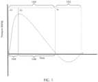
- FIG. 1depicts a typical pulse discharge from prior art electrohydraulic systems which produce a broad frequency spectrum acoustic wave (typically in the range of 16 Hz to 30 MHz) consisting of a large compressive pulse wave 100, followed by a small tensile wave 102.
- the compressive pulse wave 100consists of two parts: a fast rise acoustic front 104 (also referred to as a shock wave front) followed by a long compressive acoustic tail 106.
- the fast acoustic front 104occurs on a time scale of nanoseconds whereas the long compressive acoustic tail 106 occurs on a time scale of microseconds.
- Such prior art electrohydraulic systemscreate a pulse discharge event between two electrodes that takes place in four stages: (1) inter-electrode saline heating and initial vaporization; (2) vapor ionization; (3) inter-electrode arc formation; and (4) intense arc.
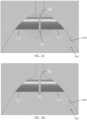
- FIG. 2Adepicts Stage 1 of the prior art pulse discharge event: inter-electrode saline heating and initial vaporization.
- a chamber 200is filled with saline 202.
- a pulse-generation systemapplies voltage directly to the electrodes 204, 206 to produce an inter-electrode conductive path 208.
- current 210is conducted through the bulk amount of saline 202 from one electrode 204 to another 206. This results in the saline 202 being heated resulting in portions of the saline 202 being vaporized at initial bubble nucleation sites located on the surface tips of the electrodes 204, 206.
- the electrode currentrises as the temperature of the saline increases. At this stage there is no electrode damage during the saline heating and initial vaporization.
- the currentis approximately evenly distributed across the surface tips of the electrodes 204, 206 and the temperature of the saline is low (up to approximately 100° C) while overall impedance is high (approximately 50 S2 for 1% saline).
- FIG. 2Bdepicts Stage 2 of the prior art pulse discharge event: inter-electrode vapor ionization, which overlaps with Stage 1 as depicted in FIG. 2A .
- current 210is still being primarily conducted through the bulk amount of saline 202 from one electrode 204 to another 206.
- Saline 202continues to vaporize and expand from the initial bubble nucleation sites. Once the saline 202 vaporizes and its density is low enough, the increased free paths of the electrons allow them to acquire the energy sufficient for collisional ionization, and avalanche plasma discharges 212 are formed.
- negligible damage to the electrodeoccurs during this stage. Ion bombardment can cause electrode material removal through sputtering, but rates are extremely low when compared to Stages 3 and 4 of the pulse discharge event. Overall impedance is high (approximately 50 S2 for 1% saline).
- FIG. 2Cdepicts Stage 3 of the prior art pulse discharge event: inter-electrode arc formation.
- the discharge through the saline vapor plasma layercauses cathode and anode spots to form on the surfaces of the electrodes. These tiny, intense jets of electrode material and electrons supply the conductive material necessary to form a full arc 214.
- the jets emanating from the cathode and anode spotsbegin to connect and transition to the intense arc of Stage 4.
- the net current across the electrodes 204, 206begins to spike as the initial arc 214 causes rapid and complete saline vaporization and arc spread. Overall impedance begins to drop from approximately 50 S2 to 0.1 ⁇ .
- FIG. 2Ddepicts Stage 4 of the prior art pulse discharge event: inter-electrode intense arc.
- the intense arc mode 216is very bright and appears to cover the anode and cathode, and fill the electrode gap 218. Another and cathode spots are present and are continuously ejecting electrode material into the gap 218 which supplies the feeder material for the low-impedance arc.
- the intense arc mode 216 produced by prior art pulse-generation systemsis characterized by sever erosion at the anode and cathode [1].
- the arc voltageis low and the current is high, due to the low overall impedance (approximately 0.1 S2).
- Anode erosionis typically more severe than cathode erosion because the anode spots tend to be fewer and more intense, while the cathode spots are mot numerous and distributed [1].
- Certain embodiments of the present apparatuses and unclaimed methodsare configured to electrohydraulically generate shockwaves while providing improved electrode lifetime. Certain embodiments achieve improved electrode lifetime by utilizing a two stage pulse discharge approach to shockwave generation.
- the pulse-generation systemin the first stage, is configured to simultaneously: (1) apply voltage pulses to a plurality of electrodes in an electrode chamber such that a portion of a liquid contained within the chamber are vaporized to provide an inter-electrode conductive path; and (2) apply voltage pulses to charge a plurality of capacitors located adjacent to the plurality of electrodes.
- the charged plurality of capacitorsdischarge to generate short inter-electrode arc through the established inter-electrode conductive path resulting in an acoustic shockwave.
- a shorter inter-electrode arccan minimize electrode erosion, and thereby lead to improved electrode lifetime.
- electrohydraulic shockwave generationhigh capacitance may be required to obtain the required peak pulse current with the desired waveform at the electrodes.
- large capacitorsmay be disposed close to the electrodes may be able to provide the high voltage pulse to the electrodes necessary to produce a short inter-electrode arc.
- the use of repeated large voltage and current phase discharges required to generate pulse shockwavesmay cause damage to large capacitors, which may in turn lead to shockwave generator failure.
- the capacitor damage sustained in these prior art systemsis theorized to be secondary to the piezoelectric effect of the capacitor plates leading to mechanical failure. This problem can limit the ability to produce a commercially viable rapid pulse shockwave generator that has an electrode lifetime of acceptable length.
- a plurality of small capacitors in parallel, arranged (e.g., in a low-inductance pattern) adjacent to the electrodes (e.g., in or on a handheld housing in which the electrodes are disposed)can be used to produce a short inter-electrode arc.
- a plurality of small capacitors in parallel, arranged in a low-inductance pattern adjacent to electrodesis able to provide the repeated and rapid large voltage and current pulse discharges required to generate rapid pulse shockwaves without damage to the capacitors.
- the piezoelectric effect on the materials for each small capacitoris limited when used within the plurality of small capacitors in parallel to generate rapid pulse shockwaves. As a result, in such embodiments, catastrophic capacitor mechanical failure is avoided, thereby improving the commercially viability of rapid pulse shockwave generators.
- a plurality of small capacitors in parallelmay be placed in a plurality of stacked circuit boards so as to condense the area required for the capacitors. Additionally, placing the plurality of small capacitors on opposing sides of each stackable circuit board results not only in further reduction of surface area required for the capacitors, but also a reduction of the inductance caused by the use of the plurality of capacitors.
- FIG. 3depicts a representative schematic of one embodiment of the disclosed electrohydraulic apparatus.
- a pulse-generation system 300is coupled to a head 302 by a cable 304.
- the head 302includes a plurality of electrodes 306 configured to define one or more spark gap 308, and a plurality of capacitors 310 (e.g., with the electrodes and capacitors carried by a housing).
- the capacitorsmay, for example, be configured in a low-inductance pattern.
- the housing or body of the head 302defines a housing within which the plurality of electrodes 306 is disposed (e.g., with a portion of each electrode extending into the chamber), and the plurality of capacitors 310 is carried by the housing (and/or may be disposed in a chamber 312 ).
- the chamber 312is configured to be filled with a liquid.
- pulse-generation system 300comprises a high voltage power supply 314, a capacitor 316, a primary switch 318, a current probe 320, a resistor 322, an inductor 324, and a voltage probe 326.
- the high voltage power supply 314may for example, be configured to supply 3000 volts (V).
- the pulse-generation system 300is configured to apply voltage pulses to the plurality of electrodes 306 such that portion of the liquid disposed in the chamber 312 are vaporized to provide an inter-electrode conductive path.
- the pulse-generation system 300is also configured to (e.g., simultaneously) apply voltage to the plurality of capacitors 310 within the chamber. Once charged, the plurality of capacitors 310 can discharge within the established inter-electrode conductive path to produce a short inter-electrode discharge arc. This discharge arc then results in the formation of a shockwave.
- FIG. 4Adepicts a bottom-up view of one embodiment of a stackable circuit board 400 having a plurality of capacitors 310 coupled to the bottom side 406 of the stackable circuit board 400.
- the stackable circuit board 400is circular, having an outer edge 402 and an center aperture 404. Surrounding the center aperture 404, the stackable circuit board 400 has a plurality of additional apertures 410 and a plurality of pins 412.
- fourteen (14) pins 412are coupled to the stackable circuit board 400.
- Other embodimentsmay include 5, 6, 7, 8, 9, 10, 11, 12, 13, 15, 16, 17, 18, 19, 20 or more pins 412 surrounding the center aperture 404.
- Pins 412may, for example, be pogo pins or other connectors configured to establish, at least temporarily, an electrical connection between multiple circuit boards.
- the stackable circuit board 400has a plurality of board-to-board connectors 414 running around its outer edge 402. Connectors 414 may be arranged in single row as shown, or in two rows, and facilitate electrically coupling the stackable circuit board 400 with additional circuit boards. Connectors 414 may, for example, be configured to operate across a range of temperatures between -55° C and 125° C.
- capacitors 310are coupled to stackable circuit boards 400 in a low inductance pattern.
- a low inductance pattern of capacitorsmay comprise a plurality of sets of capacitors, each set of capacitor comprising of a plurality of individual capacitors. In the low inductance pattern, the sets of capacitors are arranged such that each set is in parallel with each other set.
- each set of capacitorsis coupled to the stackable circuit board 400 such that one capacitor is coupled to the board 400 near the center aperture 404 and a plurality of additional capacitors are coupled to the board 400 such that they are in electrical communication with one another and extend radially away from the center aperture 404 towards the outer edge 402.
- This portion of capacitors from the setis further configured such that they are in electrical communication with an additional portion of capacitors situated on the opposing side of the board (or another board, as shown in FIGS. 6A-6D ) .
- This additional portion of capacitorsis similarly configured such that they extend in series from the edge of the board 402 towards the center aperture 404.
- the overall configuration of capacitorsis such that multiple sets of capacitors, each with a portion of the overall plurality of capacitors, extend from the center aperture 404 outward to the center edge 402, continue to the opposite side of the board (or to another board), then extend from the edge of the board 402 back towards the center aperture 404.
- Capacitors 310when so configured, may cause current to flow from the outer edge 402 of the stackable circuit board 400 towards the center aperture 404 or from the center aperture 404 of the stackable circuit board 400 towards the outer edge 402.
- Such a configurationhas been shown to result in reduced inductance across the entire capacitor array.
- certain sets of the capacitorsare configured to cause current to flow radially inward, and others of the sets of capacitors are configured to cause current to flow radially outward, resulting in "counter flows" of current that tend to cancel out or otherwise (e.g., via destructive interference), inductance during use.
- portions of the capacitorsare coupled to each of a plurality of stackable circuit boards, which may include 2, 3, 4, 5, or more individual boards.
- a stackable circuit board 400may be circular in shape, and may have a carve out 416 extending inward from outer edge 402 toward the center aperture.
- each capacitormay have a maximum capacitance of 95 nF, 90 nF, 85 nF, 80 nF, 75 nF, 70 nF, 65 nF, 60 nF, 55 nF, or 50 nF.
- the capacitorseach have a length of between 2 mm and 4 mm, and a width of between 1 mm and 3 mm.
- plurality of capacitorsmay be arranged in between 2 and 20 sets of capacitors, with the sets connected in parallel (e.g., and the capacitors within each set connected in series).
- the plurality of capacitorsmay comprise 2, 5, 10, or 15 sets of capacitors.
- each set of capacitorscomprises fewer than 50 capacitors, but may alternatively comprise 5, 10, 15, 20, 25, 30, 35, 40, or 45 capacitors per set.
- the plurality of capacitorscomprises at least 100 capacitors.
- the plurality of capacitorsare arranged in a circuit having an overall inductance of between 2 nH and 200 nH.
- FIGS. 5A-5Edepict perspective, cross-sectional, top, and side views of one embodiment of the present assemblies of stackable circuit boards including a capacitor array for use in shockwave pulse generating apparatuses.
- FIG. 5Adepicts a perspective view of one embodiment of the present stackable circuit board assemblies;
- FIG. 5Bdepicts another perspective view of the assembly;
- FIG. 5Cdepicts a side cross-sectional view of the assembly;
- FIG. 5Ddepicts a top view of the assembly;
- FIG. 5Edepicts a side view of the assembly.
- circuit board 400is coupled to the second stackable circuit board 500 via connectors 414 such that capacitors 310 of circuit board 400 are electrically connected to second stackable circuit board 500 via the connectors (414).
- Circuit board 400is also mechanically coupled to circuit board 500 via a central hub assembly 502. According to this embodiment, Circuit board 500 provides the low-inductance return path from the central pin to the outermost row of capacitors 310.
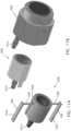
- FIGS. 6A-6Ddepict perspective, cross-sectional, and exploded perspective views of another embodiment of the present capacitor array for use in the rapid therapeutic shockwave generation apparatuses and unclaimed methods.
- FIG. 6Adepicts a perspective view of the capacitor array
- FIG. 6Bdepicts a second perspective view of the capacitor array
- FIG. 6Cdepicts a cross-sectional view of the capacitor array
- FIG. 6Ddepicts an exploded view of the capacitor array.
- the plurality of capacitors 310is placed on a first stacked circuit board 400 and a second stacked circuit board 500, adjacent to a plurality of electrodes wherein the plurality of small capacitors 310 is placed on opposing sides of each stackable circuit board 400, 500 in a low-inductance pattern.
- the circuit boards 400, 500are both electrically coupled to each other via board-to-board connectors 414 and mechanically coupled to each other via a central mechanical assembly 502.
- locating the plurality of capacitors 310 near the electrodesenables the arc to be discharged completely and quickly. Once the capacitors 310 within the chamber head (as illustrated by the embodiment depicted in FIG. 3 ) are discharged, the inter-electrode arc ends, minimizing electrode erosion.
- the improved lifetime of the electrodesis the result of the discharge of the plurality of capacitors 310 near the electrodes. Locating the plurality of capacitors 310 near the electrodes in a low inductance pattern provides the capacitor/electrode setup with an overall low inductance. As a result, the plurality of capacitors 310 within the chamber is able to be discharge completely and quickly.
- the central mechanical assembly 502comprises a contact ring 600, a ring adapter 602, a spacer 604, a replacement pin socket 606, a center pin 608, and a plurality of nuts 610.
- the ring adapter 602may have a plurality of teeth 612 that are configured to be inserted into apertures in the second stackable circuit board 500 such that the teeth 612 prevent the second stackable circuit board 500 from rotating independent from the ring adapter 602.
- the capacitorsmay be configured to cause current to flow from the center of the second stackable circuit board 500 towards its outer edge, through the board-to-board connectors 414 to the outer edge of the first stackable circuit board 400 and from there to the center of the first stackable circuit board 400.
- Each stackable circuit board 400, 500may have a thickness of between 0.5 mm to 5 mm (0.02 inches to 0.2 inches).
- the boards 400, 500may have thicknesses of between 0.76 and 3.18 mm (0.03 and 0.125 inches), or between 1 and 2.54 mm (0.04 and 0.1 inches).
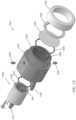
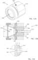
- FIGS. 7A-7Cdepict cross-sectional and side views of one embodiment of the disclosed capacitor array coupled shockwave generation chamber.
- the capacitor array 700is coupled to plurality of electrodes comprising a proximal electrode 702 and a distal electrode 704.
- both the proximal electrode 702 and the distal electrode 704are disposed in a chamber 706, which is configured to be filled with liquid.
- the chamber 706is configured to be filled with saline.
- the chamber 706is filled with saline.
- the electrodes 702, 704are configured to have a short gap between them defining the discharge location 708.
- the capacitor array 700along with the coupled electrodes 702, 704 and chamber 706, is configured to perform the two stage discharge approach to shockwave generation.
- the pulse-generation systemis configured to simultaneously: (1) apply voltage pulses to a plurality of electrodes 702, 704 in an electrode chamber 706 such that a portion of a liquid contained within the chamber 706 is vaporized to provide an inter-electrode conductive path in the discharge location 708; and (2) apply voltage pulses to charge a plurality of capacitors located adjacent to the plurality of electrodes 702, 704 in the capacitor array 700.
- the charged plurality of capacitorsdischarge to generate short inter-electrode arc through the established inter-electrode conductive path in the discharge location 708 resulting in an acoustic shockwave.
- using a two stage pulse discharge approach to generating shock wavesresults in a short inter-electrode arc times that minimizes electrode erosion, leading to improved electrode lifetime.
- Electrohydraulic systems that use a single stage pulse discharge approachsuffer from long discharge arc times, and therefore significant electrode erosion. This significant electrode erosion leads to an electrohydraulic shockwave apparatus with short electrode lifetime, increasing the time and expenses necessary for maintenance.
- FIGS. 8A and 8Bdepict photos comparing an electrode used by a prior art system compared to an electrode implementing the disclosed system.
- FIG. 8Adepicts one embodiment of an electrode run with a prior art pulsed power supply using the single stage approach.
- FIG. 8Bdepicts an electrode run with one embodiment of the two-stage pulsed generation system disclosed herein.
- the electrode run using the prior art pulsed power supplyFIG. 8A
- the electrode run using the prior art pulsed power supplyFIG. 8A
- the electrode run using the prior art pulsed power supplyFIG. 8A
- the electrode run using the prior art pulsed power supplyshowed significant erosion after less than 100 pulses. Large cratering indicates bulk electrode melt due to extended severe arc duration resulting from the single stage prior art system.
- the electrode run with the two-stage pulse generation systemFIG.
- the electrode implementing the two-stage systemhad a wear rate reduction of 15X when compared to that of implementing the prior art system.
- the electrodes depicted in FIG. 8A coupled to a prior art pulse-generation systemexhibited a wear rate of approximately 0.095 mm (3,750 micro-inches) per minute
- the electrodes depicted in FIG. 8B coupled to one of the present, inventive two-stage pulse-generation approachesexhibited a wear rate of only 0.006 mm (250 micro-inches) per minute.
- apparatuses and unclaimed method for electrohydraulic generation of shockwaves using the two-stage approach disclosed hereingenerate acoustic waves that are "compressed" when compared to those waves generated by prior art systems.
- FIG. 9depicts a graph illustrating the pressure over time of an acoustic wave generated by both the prior art system 900 as well as an acoustic wave generated by the proposed two-stage approach 902.
- the acoustic wave generated by the two-stage approachhas a faster rise acoustic front 904 than that of the prior art approach.
- the long acoustic tail 906is significantly compressed as a result of the fast capacitor discharge time into an already established inter-electrode conductive path.
- the two-stage approachputs more energy into the acoustical pulse and less total energy into the arc when compared to the prior art approach. Less total energy into the arc directly leads to improved electrode life.
- the compressed acoustic waves depicted in FIG. 9are less painful and damaging when applied to tissue.
- the typical pulse discharge from prior art electrohydraulic systemsproduce a broad frequency spectrum acoustic wave, typically in the range of 16 Hz to 30 MHz.
- the long compressive tail 906 of the acoustic waveis composed of the lower frequency spectrum of the acoustic wave. These low frequency components, at the acoustic pressures that are typically used, are the main source of large cavitation bubbles. These large cavitation bubbles, when generated in tissue, result in pain and tissue damage. Due to the short capacitor discharge and the resulting fast arc, the long compressive tail 906 of the acoustic wave is compressed. As a result, large cavitation bubbles secondary to a long tail are minimized.
- probe 1000comprises: a housing 1002 defining a chamber 1004 and a shockwave outlet 1006; a liquid disposed in chamber 1004; a plurality of electrodes 306 (e.g. in spark head or module 1008 ) configured to be disposed in the chamber to define one or more spark gaps; and is configured to be coupled to a pulse generation system (300) configured to apply voltage pulses to the electrodes at a rate of between 10 Hz and 5 MHz.
- a pulse generation system300
- spark head 1008includes a sidewall or body 1010 and a plurality of electrodes 306 that defined a spark gap.
- probe 1000is configured to permit liquid to be circulated through chamber 1004 via liquid connectors or ports 1012 and 1014, one of which is coupled to the spark head 1008 and the other of which is coupled to housing 1002, as shown.
- housing 1002is configured to receive spark head 1008, as shown, such that housing 1002 and housing 1010 cooperate to define chamber 1004 (e.g., such that spark head 1008 and housing 1002 include a complementary parabolic surfaces that cooperate to define the chamber).
- housing 1002 and spark head 1008includes a channel 1016 (e.g., along a central longitudinal axis of spark head 1008 ) extending between liquid connector 1012 and chamber 1004 and aligned with the spark gap been electrodes 306 such that circulating water will flow in close proximity and/or through the spark gap.
- housing 1002includes a channel 1018 extending between liquid connector 1014 and chamber 1004.
- housing 1010includes a groove 1020 configured to receive a resilient gasket or O-ring 1022 to seal the interface between spark head 1008 and housing 1002, and housing 1002 includes a groove 1024 configured to receive a resilient gasket or O-ring 1026 to seal the interface between housing 1002 and cap member 1028 when cap member 1028 is secured to housing 1002 by ring 1030 and restraining collar 1032.
- electrodes 306each includes a flat bar potion 1034 and a perpendicular cylindrical portion 1036 (e.g., comprising tungsten for durability) in electrical communication (e.g., unitary with) bar portion 1034 such that cylindrical portion 1036 can extend through a corresponding opening 1038 in spark head 1008 into chamber 1004, as shown.
- part of the sides of cylindrical portion 1036can be covered with an electrically insulative and/or resilient material (e.g., shrink wrap) such as, for example, to seal the interface between portion 1036 and housing 1010.
- housing 1010also includes longitudinal grooves 1038 configured to receive bar portions 1034 of electrodes 306.
- housing 1002also includes set screws 1040 positioned to align with cylindrical portions 1036 of electrodes 306 when spark head 1008 is disposed in housing 1000, such that set screws 1040 can be tightened to press cylindrical portions 1036 inward to adjust the spark gap between the cylindrical portions of electrodes 306.
- spark head 1008is permanently adhered to housing 1002; however, in other embodiments, spark head 1008 may be removable from housing 1002 such as, for example, to permit replacement of electrodes 306 individually or as part of a new or replacement spark head 1008.
Landscapes
- Health & Medical Sciences (AREA)
- Life Sciences & Earth Sciences (AREA)
- Surgery (AREA)
- Engineering & Computer Science (AREA)
- Animal Behavior & Ethology (AREA)
- General Health & Medical Sciences (AREA)
- Public Health (AREA)
- Veterinary Medicine (AREA)
- Biomedical Technology (AREA)
- Nuclear Medicine, Radiotherapy & Molecular Imaging (AREA)
- Molecular Biology (AREA)
- Vascular Medicine (AREA)
- Orthopedic Medicine & Surgery (AREA)
- Heart & Thoracic Surgery (AREA)
- Medical Informatics (AREA)
- Mechanical Engineering (AREA)
- Radiology & Medical Imaging (AREA)
- Physics & Mathematics (AREA)
- Acoustics & Sound (AREA)
- Multimedia (AREA)
- Epidemiology (AREA)
- Pain & Pain Management (AREA)
- Physical Education & Sports Medicine (AREA)
- Rehabilitation Therapy (AREA)
- Surgical Instruments (AREA)
- Electrotherapy Devices (AREA)
Description
- This application claims the benefit of
U.S. Provisional application No. 62/365,099 filed July 21, 2016 - The present invention relates generally to therapeutic uses for shock waves or shockwaves. More particularly, but not by way of limitation, the present invention relates to an apparatus for generating therapeutic shock waves or shockwaves (shock waves with therapeutic uses) with improved electrode lifetime.
- Acoustic Shockwaves have been used for certain therapies for a number of years. "Shock wave" or "shockwave" is generally used to refer to an acoustic phenomenon (e.g., resulting from an explosion or lightning) that creates a sudden and intense change in pressure. These intense pressure changes can produce strong waves of energy that can travel through elastic media such as air, water, human soft tissue, or certain solid substances such as bone, and/or can induce an inelastic response in such elastic media. Methods for creating shock waves for therapeutic uses include: (1) electrohydraulic, or spark gap (EH); (2) electromagnetic, or EMSE; and (3) piezoelectric. Each is based upon its own unique physical principles.
US Patent Application 13/574,228 (a national-stage application ofPCT/US2011/021692 , which published asWO 2011/091020 A1 ), by one of the present inventors, discloses a device for producing shock waves at a high pulse rate using a transducer. That device includes an acoustic-wave generator configured to emit acoustic waves having at least one frequency between 1 MHz and 1000 MHz; a shockwave housing coupled to the acoustic-wave generator; and a shockwave medium disposed in the shockwave housing; where the apparatus is configured such that if the acoustic-wave generator emits acoustic waves then at least some portion of the acoustic waves will travel through the shockwave medium and form shock waves. That device can be actuated to form shock waves configured to cause particles within a patient to rupture one or more cells of the patient, and the shock waves can be directed to cells of a patient such that the shock waves cause particles to rupture one or more of the cells. This acoustic-transducer device can produce high powered shockwaves at high frequencies or pulse rates.- Additionally,
US Patent Application 13/798712 , also by the present inventors, discloses apparatuses and methods for electrohydraulic generation of shockwaves at a rate of 10 Hz and 5 MHz comprising: a housing defining a chamber and a shockwave outlet; a liquid disposed in the chamber; a plurality of electrodes (e.g., in a spark head or module) configured to be disposed in the chamber to define one or more spark gaps; and a pulse-generation system configured to apply voltage pulses to the electrodes at a rate of between 10 Hz and 5 MHz. - Other systems for producing shockwaves can include an electrohydraulic (EH) wave generator. EH systems can generally deliver similar levels of energy as other methods, but may be configured to deliver that energy over a broader area, and therefore deliver a greater amount of shock wave energy to targeted tissue over a shorter period of time. EH systems generally incorporate an electrode (i.e., a spark plug) to initiate a shock wave. In EH systems, high energy shock waves are generated when electricity is applied to an electrode immersed in treated water contained in an enclosure. When the electrical charge is fired, a small amount of water is vaporized at the tip of the electrode and the rapid, nearly instantaneous, expansion of the vaporized water creates a shock wave that propagates outward through the liquid water. In some embodiments, the water is contained in an ellipsoid enclosure. In these embodiments, the shock wave may ricochet from the sides of the ellipsoid enclosure and converge at a focal point that coincides with the location of the area to be treated.
- For example,
U.S. Patent No 7,189,209 (the '209 Patent) describes a method of treating pathological conditions associated with bone and musculoskeletal environments and soft tissues by applying acoustic shock waves. The '209 Patent describes that shockwaves induce localized trauma and cellular apoptosis therein, including micro-fractures, as well as to induce osteoblastic responses such as cellular recruitment, stimulate formation of molecular bone, cartilage, tendon, fascia, and soft tissue morphogens and growth factors, and to induce vascular neoangiogenesis. The '209 Patent claims several specific implementations of its method. For instance, the '209 Patent claims a method of treating a diabetic foot ulcer or a pressure sore, comprising: locating a site or suspected site of the diabetic foot ulcer or pressure sore in a human patient; generating acoustic shock waves; focusing the acoustic shock waves throughout the located site; and applying more than 500 to about 2500 acoustic shock waves per treatment to the located site to induce micro-injury and increased vascularization thereby inducing or accelerating healing. The '209 Patent discloses a frequency range of approximately 0.5-4 Hz, and application of about 300 to 2500 or about 500 to 8,000 acoustic shock waves per treatment site, which can result in a treatment duration for each treatment site and/or a "total time per treatment" for all sites that is inconveniently large. For example, the '209 Patent discloses total times per treatment for different examples ranging from 20 minutes to 3 hours. U.S. Patent 5,529,572 (the `572 Patent) includes another example of the use of electro-hydraulically generated shockwaves to produce therapeutic effect on tissues. The '572 Patent describes a method of increasing the density and strength of bone (to treat osteoporosis), comprising subjecting said bone to substantially planar, collimated compressional shock waves having a substantially constant intensity as a function of distance from a shock wave source, and wherein said collimated shock waves are applied to the bone at an intensity of 50-500 atmospheres. The '572 Patent describes the application of unfocussed shock waves to produce dynamic repetitive loading of the bone to increase mean bone density, and thereby strengthen bone against fracture. As described in the `572 Patent, "the unfocussed shock waves preferably are applied over a relatively large surface of the bone to be treated, for example to cover an area of from 10 to 150 cm2. The intensity of the shock waves may be from 50-500 atmospheres. Each shock wave is of duration of a few microseconds, as in a conventional lithotripter, and is preferably applied at a frequency of 1-10 shock waves per second for a period of 5-30 minutes in each treatment. The number of treatments depends on the particular patient."U.S. Patent Application No. 10/415, 293 (the `293 Application), which is also published asUS 2004/0006288 , discloses another embodiment of the use of EH-generated shockwaves to provide a therapeutic effect on tissues. The `293 Application discloses a device, system, and method for the generation of therapeutic acoustic shock waves for at least partially separating a deposit from a vascular structure. The `293 Application describes that the device can produce shockwaves at a pulse rate of about 50 to about 500 pulses per minute (i.e., 0.83 to 8.33 Hz) with a number of pulses per treatment site (in terms of per length of vascular unit being treated) from about 100 to about 5,000 per 1 cm2.- Prior art literature has indicated that faster pulse rates using EH systems to provide shockwaves can lead to tissue damage. For example, in one study (Delius, Jordan, & et al, 1988) [2], the effect of shock waves on normal canine kidneys was examined in groups of dogs whose kidneys were exposed to 3000 shockwaves. The groups differed only in the rate of shockwave administration which was 100 Hz and 1 Hz, respectively. Autopsy was performed 24 to 30 hours later. Macroscopically and histologically, significantly more hemorrhages occurred in kidney parenchyma if shockwaves were administered at a rate of 100 Hz (vs 1 Hz). The results showed that kidney damage is dependent on the rate of shockwave administration.
- In another study (Madbouly & et al, 2005) [7], slow shockwave lithotripsy rate (SWL) was associated with a significantly higher success rate at a lower number of total shockwaves compared to the fast shockwave lithotripsy rate. In this paper, the authors discussed how human studies have also shown a decrease in the incidence of SWL induced renal injury or need for anesthesia when slower rates of test SWL were used.
- In yet another study (Gillitzer & et al, 2009) [5], slowing the delivery rate from 60 to 30 shockwaves per minute also provides a dramatic protective effect on the integrity of real vasculature in a porcine model. These findings support potential strategies of reduced pulse rate frequency to improve safety and efficacy in extracorporeal shockwave lithotripsy.
- Soft tissues may transition from elastic to viscous behavior for pulse rates (PRs) between 1 Hz and 10 Hz. As a result, potential damage to tissue from shockwaves at PRs between 1 Hz and 10 Hz is unpredictable when typical lithotripsy power levels are used. Perhaps as a result, the prior art teaches slower PRs and large total times per treatment (TTPT). For example, currently known EH shockwave systems generally deliver PRs of less than 10 Hz and require large total times per treatment (TTPT) (e.g., TTPT periods of minutes or even hours for even a single treatment site). When, as may be typical, a treatment requires repositioning of a device at multiple treatment sites, the TTPT becomes large and potentially impractical for many patients and treatment needs.
- While long treatment times may be acceptable for extracorporeal Shockwave lithotripsy, the use of Shockwaves to provide non-lithotripsy therapeutic effects on tissue in the medical setting is less than optimal if not impractical. For example, the cost of treatment often increases with the time needed to administer a treatment (e.g., due to the labor, facilities and other resource costs allocated to the administration of the treatment). Furthermore, in addition to costs, at some point the duration of providing treatment to the patient becomes unbearable for the patient receiving, and healthcare staff providing, the treatment.
WO 91/10227 A1 US 3 364 708 A discloses a method of generating explosive simulating shock waves.WO 2015/176001 A1 discloses radiofrequency pulse amplifier systems that incorporate an energy array comprising multiple capacitors connected in parallel.DE 10 2007 046 902 A1 discloses a pulse generator for a shock wave therapy apparatus. A spark discharge mean comprises an energy source, at least one capacitor, and at least one switching element.US 5 509 200 A discloses techniques for fabricating fine pitch pattern multilayer printed circuit boards.- This disclosure includes embodiments of apparatuses for electrohydraulic generation of rapid acoustic pulses that have improved electrode lifetime. According to the invention, an apparatus as recited in the independent claim is provided. The dependent claims define embodiments. In certain embodiments, this improved electrode lifetime is achieved by utilizing a two stage pulse discharge approach to shock wave generation. According to these embodiments, in the first stage, the pulse-generation system is configured to simultaneously apply voltage pulses to the plurality of electrodes in the electrode chamber such that portions of the liquid contained therein are vaporized to provide an inter-electrode conductive path; and, to apply voltage pulses to a plurality of capacitors located adjacent to said electrodes to charge said plurality of capacitors. In the second stage, the charged plurality of capacitors discharge to the electrodes to generate a short inter-electrode arc, through the established inter-electrode conductive path, resulting in an acoustic shock wave. The short inter-electrode arc minimizes electrode erosion leading to improved electrode lifetime.
- The improved lifetime of the electrodes is the result of the fast discharge of the capacitors located adjacent to the electrodes within the chamber. The pulse-generation system is configured to simultaneously apply voltage pulses to the plurality of electrodes in the electrode chamber such that portions of the liquid are vaporized to provide an inter-electrode conductive path; and, to apply voltage pulses to the plurality of capacitors located adjacent to said electrodes to charge said plurality of capacitors. In one embodiment, the plurality of capacitors comprises at least 10 planar capacitors in parallel wherein each capacitor has a capacitance of no greater than 100 nanofarad. In one embodiment, the plurality of planar capacitors is placed on a plurality of stacked circuit boards adjacent to the electrodes and wherein the plurality of planar capacitors is placed on opposing sides of each stackable circuit board in a low-inductance pattern. Locating these capacitors adjacent to the electrodes enables the arc to discharge completely and quickly. Once the capacitors are discharged, the inter-electrode arc ends, which minimizes electrode erosion.
- Some embodiments of the present apparatuses (e.g., for generating therapeutic shock waves) comprise: a housing defining a chamber and a shockwave outlet; a liquid disposed in the chamber; a plurality of electrodes configured to be disposed in the chamber to define one or more spark gaps; a plurality of capacitors carried by the housing and in electrical communication with the plurality of electrodes; and a pulse-generation system configured to be coupled to the plurality of electrodes such that: (i) the housing is movable relative to the pulse-generation system, and (ii) the pulse-generation system is in electrical communication with the plurality of electrodes and the plurality of capacitors; where the pulse-generation system is configured to apply voltage pulses simultaneously to: the plurality of electrodes (e.g., to begin to vaporize and ionize portions of the liquid to provide at least one inter-electrode conductive path between the plurality of electrodes, and the plurality of capacitors to charge the plurality of capacitors); and where the plurality of capacitors are configured to, upon reaching a threshold charge, discharge to the plurality of electrodes to generate one or more arcs along the one or more inter-electrode conductive paths to vaporize additional portions of the liquid and generate one or more acoustic shock waves.
- In some embodiments of the present apparatuses, the pulse-generation system is configured to provide an inter-electrode conductive path by applying voltage to charge the plurality of capacitors during the period that the pulse generation system applies voltage to the plurality of electrodes.
- Some embodiments of the present apparatuses (e.g., for generating therapeutic shock waves) comprise: a housing defining a chamber and a shockwave outlet, the chamber being configured to be filled with a liquid; a plurality of electrodes configured to be disposed in the chamber to define one or more spark gaps; a plurality of capacitors carried by the housing and in electrical communication with the plurality of electrodes; and a pulse-generation system configured to be coupled to the plurality of electrodes such that: (i) the housing is movable relative to the pulse-generation system, and (ii) the pulse-generation system is in electrical communication with the plurality of electrodes and the plurality of capacitors; where the pulse-generation system is configured to apply voltage pulses simultaneously to: the plurality of electrodes (e.g., to begin to vaporize and ionize portions of the liquid to provide at least one inter-electrode conductive path between the plurality of electrodes), and the plurality of capacitors to charge the plurality of capacitors; where the plurality of capacitors are configured to, upon reaching a threshold charge, discharge to the plurality of electrodes to generate one or more arcs along the one or more inter-electrode conductive paths to vaporize additional portions of the liquid and generate one or more acoustic shock waves.
- Some embodiments of the present apparatuses (e.g., for generating therapeutic shock waves) comprise: a housing defining a chamber and a shockwave outlet, the chamber being configured to be filled with a liquid; a plurality of electrodes configured to be disposed in the chamber to define one or more spark gaps; a plurality of capacitors carried by the housing and in electrical communication with the plurality of electrodes; and where the plurality of electrodes is configured to be coupled to a pulse-generation system such that: (i) the housing is movable relative to the pulse-generation system, and (ii) the pulse-generation system is in electrical communication with the plurality of electrodes and the plurality of capacitors such that the plurality of electrodes and the plurality of capacitors can simultaneously receive voltage pulses from the pulse-generation system; and where the plurality of capacitors are configured to, upon reaching a threshold charge, discharge to the plurality of electrodes.
- In some embodiments of the present apparatuses, each of the plurality of capacitors is planar. In some embodiments, the plurality of capacitors are arranged in a circuit having an overall inductance of between 2 nH and 200 nH. In some embodiments, the plurality of capacitors comprises between 2 and 20 sets of capacitors with the sets of capacitors connected in parallel. In some embodiments, each set of capacitors comprises fewer than 50 capacitors. In some embodiments, each set of capacitors comprises 10 or more capacitors in series.
- In some embodiments of the present apparatuses, each capacitor has a capacitance of no greater than 100 nanofarad.
- In some embodiments of the present apparatuses, the plurality of capacitors is coupled to a plurality of stackable circuit boards. In some embodiments, the plurality of capacitors are arranged in a plurality of circular patterns. In some embodiments, the plurality of stackable circuit boards comprises a first stackable circuit board, and a second stackable circuit board coupled to the first stackable circuit board. In some embodiments, a first portion of the plurality of capacitors is coupled to the first stackable circuit board, and a second portion of the plurality of capacitors is coupled to the second stackable circuit board. In some embodiments, the first portion of the plurality of capacitors is disposed on a first side of a first stackable circuit board, and the second portion of the plurality of capacitors is disposed on a second side of a second stackable circuit board, and the second side of the second circuit board is opposite the first side of the first stackable circuit board. In some embodiments, the first stackable circuit board and the second stackable circuit board are circular. In some embodiments, a first portion of the plurality of capacitors is coupled to the first stackable circuit board and a second portion of the plurality of capacitors is coupled to the second stackable circuit board. In some embodiments, the first portion of the plurality of capacitors is coupled to the first stackable circuit board in a circular pattern; and the second portion of the plurality of capacitors is coupled to the second stackable circuit board in a circular pattern. In some embodiments, each set of capacitors comprises 10 or more capacitors in series. In some embodiments, the first stackable circuit board further comprises an outer edge and a center, the second stackable circuit board further comprises an outer edge and a center; and the first portion of the plurality of capacitors is configured to cause current to flow from the outer edge of the first stackable circuit board towards the center of the first stackable circuit board, and the second portion of the plurality of capacitors is configured to cause current to flow from the outer edge of the second stackable circuit board towards the center of the second stackable circuit board. In some embodiments, the first stackable circuit board is electrically coupled to the second stackable circuit board by connectors disposed along the outer edges of the stackable circuit boards. In some embodiments, the plurality of stackable circuit boards each have a thickness of between 0.5 mm to 5 mm (0.02 inches to 0.2 inches).
- In some embodiments of the present apparatuses, the plurality of capacitors each have length of between 2 mm and 4 mm, and a width of between 1 mm and 3 mm.
- In some embodiments of the present apparatuses, the plurality of capacitors comprises at least 100 capacitors.
- Some embodiments of the present capacitor-array apparatus (e.g., for use in generating therapeutic shock waves) comprise: one or more circuit boards; and a plurality of capacitors coupled to the one or more circuit boards; where a first portion of the capacitors is arranged in a first pattern defined by a plurality of capacitor sets, a second portion of the plurality of capacitors is arranged in a second pattern defined by a plurality of capacitor sets, each capacitor set comprises two or more of the capacitors connected in series; the capacitor sets defining the first pattern are connected in parallel, and the capacitor sets defining the second pattern are connected in parallel; and where the one or more circuit boards are configured to be coupled to an electrode such that the electrode is in electrical communication with the capacitors and is fixed in at least two degrees of freedom relative to the one or more circuit boards.
- In some embodiments of the present capacitor-array apparatuses, the plurality of capacitors are planar. In some embodiments, the plurality of capacitors are arranged in a circuit having an overall inductance of between 2 nH and 200 nH. In some embodiments, the plurality of capacitors comprises between 2 and 20 sets of capacitors with the sets of capacitors connected in parallel. In some embodiments, each set of capacitors comprises fewer than 50 capacitors.
- In some embodiments of the present capacitor-array apparatuses, each set of capacitors comprises 10 or more capacitors in series.
- In some embodiments of the present capacitor-array apparatuses, each capacitor has a capacitance of no greater than 100 nanofarads.
- In some embodiments of the present capacitor-array apparatuses, the one or more circuit boards comprises a plurality of stackable circuit boards. In some embodiments, the first and second patterns are circular. In some embodiments, the plurality of stackable circuit boards comprises a first stackable circuit board, and a second stackable circuit board coupled to the first stackable circuit board. In some embodiments, the first portion of the capacitors is coupled to the first stackable circuit board, and the second portion of the capacitors is coupled to the second stackable circuit board. In some embodiments, the first portion of the capacitors is disposed on a first side of a first stackable circuit board, and the second portion of the plurality of capacitors is disposed on a second side of a second stackable circuit board, and the second side of the second circuit board is opposite the first side of the first stackable circuit board. In some embodiments of the present capacitor-array apparatuses, the first portion of the plurality of capacitors is coupled to the first stackable circuit board in a circular pattern; and the second portion of the plurality of capacitors is coupled to the second stackable circuit board in a circular pattern. In some embodiments, each set of capacitors further comprises 10 or more capacitors connected in parallel. In some embodiments, the first stackable circuit board further comprises an outer edge and a center, the second stackable circuit board further comprises an outer edge and a center; and the first portion of the plurality of capacitors is configured to cause current to flow from the outer edge of the first stackable circuit board towards the center of the first stackable circuit board, and the second portion of the plurality of capacitors is configured to cause current to flow from the outer edge of the second stackable circuit board towards the center of the second stackable circuit board. In some embodiments, the first stackable circuit board is electrically coupled to the second stackable circuit board by connectors disposed along the outer edges of the stackable circuit boards. In some embodiments, the plurality of stackable circuit boards each have a thickness of between 0.5 mm to 5 mm (0.02 inches to 0.2 inches).
- In some embodiments of the present capacitor-array apparatuses, the plurality of capacitors each have length of between 2 mm and 4 mm, and a width of between 1 mm and 3 mm.
- In some embodiments of the present capacitor-array apparatuses, the plurality of capacitors comprises at least 100 capacitors.
- Some embodiments of the present unclaimed methods (e.g., of producing a compressed acoustic wave using an apparatus for generating therapeutic shock waves), comprising: applying voltage pulses to a plurality of electrodes in a chamber defined by a housing and filled with liquid such that portions of the liquid begin to vaporize and ionize to provide an inter-electrode conductive path; applying voltage to a plurality of capacitors carried by the housing and in electrical communication with the plurality of electrodes to charge the plurality of capacitors; and upon the plurality of capacitors reaching a threshold charge, discharging the plurality of capacitors to the electrodes to generate an inter-electrode arc along the established inter-electrode conductive path and thereby generate of at least one acoustic shock wave. In some embodiments, the voltage pulses applied to the plurality of electrodes is between 500 V and 10,000 volts (V). In some embodiments, the voltage pulses applied to the plurality of capacitors is between 500 V and 10,000 V.
- The term "coupled" is defined as connected, although not necessarily directly, and not necessarily mechanically; two items that are "coupled" may be unitary with each other. The terms "a" and "an" are defined as one or more unless this disclosure explicitly requires otherwise. The term "substantially" is defined as largely but not necessarily wholly what is specified (and includes what is specified; e.g., substantially 90 degrees includes 90 degrees and substantially parallel includes parallel), as understood by a person of ordinary skill in the art. In any disclosed embodiment, the terms "substantially," "approximately," and "about" may be substituted with "within [a percentage] of" what is specified, where the percentage includes .1, 1, 5, and 10 percent. In the disclosed embodiment, the term "adjacent" is generally defined located in the same discrete chamber, housing, or module.
- The terms "comprise" (and any form of comprise, such as "comprises" and "comprising"), "have" (and any form of have, such as "has" and "having"), "include" (and any form of include, such as "includes" and "including") and "contain" (and any form of contain, such as "contains" and "containing") are open-ended linking verbs. As a result, a system or apparatus that "comprises," "has," "includes" or "contains" one or more elements possesses those one or more elements, but is not limited to possessing only those elements. Likewise, a method that "comprises," "has," "includes" or "contains" one or more steps possesses those one or more steps, but is not limited to possessing only those one or more steps.
- Further, a structure (e.g., a component of an apparatus) that is configured in a certain way is configured in at least that way, but it can also be configured in other ways than those specifically described.
- Any embodiment of any of the present systems, apparatuses, and methods can consist of or consist essentially of - rather than comprise/include/contain/have - any of the described steps, elements, and/or features. Thus, in any of the claims, the term "consisting of" or "consisting essentially of" can be substituted for any of the open-ended linking verbs recited above, in order to change the scope of a given claim from what it would otherwise be using the open-ended linking verb.
- Details associated with the embodiments described above and others are presented below.
- The invention is defined by appended independent claim 1 and preferred embodiments by the appended dependent claims.
- The following drawings illustrate by way of example and not limitation. For the sake of brevity and clarity, every feature of a given structure is not always labeled in every figure in which that structure appears. Identical reference numbers do not necessarily indicate an identical structure. Rather, the same reference number may be used to indicate a similar feature or a feature with similar functionality, as may non-identical reference numbers. The figures are drawn to scale (unless otherwise noted), meaning the sizes of the depicted elements are accurate relative to each other for at least the embodiment depicted in the figures.
FIG. 1 is a graph illustrating an acoustic wave from prior art electrohydraulic systems.FIG. 2A depicts stage 1 of a pulse generation system: inter-electrode saline heating and initial vaporization.FIG. 2B depicts stage 2 of a pulse generation system: inter-electrode vapor ionization.FIG. 2C depicts stage 3 of a pulse generation system: inter-electrode arc formation.FIG. 2D depicts stage 4 of a pulse generation system: inter-electrode intense arc.FIG. 3 depicts a schematic diagram of one embodiment of an electrohydraulic shock wave generation system for use in or with some embodiments of the present systems.FIG. 4A-4E depict various views of one embodiment of a stackable circuit board comprising a plurality of capacitors.FIGS. 5A-5E depict various views of a second embodiment of a capacitor array affixed to a pair of coupled stackable circuit boards.FIGS. 6A-6D depict various views of a capacitor array affixed to a pair of coupled stackable circuit boards and coupling components.FIGS. 7A-7C depict various views of a capacitor array affixed to a pair of stackable circuit boards coupled to a pair of electrodes in a shock wave generation chamber.FIGS. 8A and8B depict the reduced electrode wear resulting from the use of one embodiment of the present apparatus when compared to prior art systems.FIG. 9 depicts a graph illustrating a comparison of compressed acoustic wave from an embodiment of the present apparatus and an acoustic wave from a prior art apparatus.FIG. 10 depicts an exploded perspective view of a further prototyped embodiment of the present probes having a spark head or module.FIGS. 11A and11B depict parts of the assembly of the probe ofFIG. 10 .FIGS. 12A and12B depict perspective and side cross-sectional views, respectively of the probe ofFIG. 10 .FIG. 12C depicts an enlarged side cross-sectional view of a spark gap of the probe ofFIG. 10 .- Certain embodiments of the present systems and apparatuses are configured to generate high-frequency shock waves while having an improved electrode lifetime. In some embodiments, the generated EH shock waves can be used in medical and/or aesthetic therapeutic applications (e.g., when directed at and/or delivered to target tissue of a patient). Examples of medical and/or aesthetic therapeutic applications in which the present systems can be used are disclosed in: (1)
U.S. Patent Application No. 13/574,228 , published asUS 2013/0046207 ; (2)U.S. Patent Application No. 13/547,995 , published as, published asUS 2013/0018287 ; and (3)U.S. Patent Application No. 13/798,710 , published asUS 2014/0257144 . - In one embodiment, the apparatus for electrohydraulic generation of shockwaves comprises: a housing defining a chamber and a shockwave outlet; a liquid disposed in the chamber; a plurality of electrodes (e.g., in the spark head or module) configured to be disposed in the chamber to define one or more spark gaps; and a pulse generation system configured to apply voltage pulses to the electrodes at a rate of between 10 Hz and 5 MHz. The rate of voltage pulses may be at rates of 25 Hz, 50 Hz, 75 Hz, 100 Hz, 150 Hz, 200 Hz, 250 Hz, 300 Hz, 400 Hz, 500 Hz, 600 Hz, 700 Hz, 800 Hz, 900 Hz, 1 KHz, 5 KHz, 10 KHz, 25 KHz, 50 KHz, 100 KHz, 200 KHz, 300 KHz, 400 KHz, 500 KHz, 600 KHz, 700 KHz, 800 KHz, 900 KHz, 1 MHz, 2 MHz, 3 MHz, and 4 MHz.
- Referring now to the drawings,
FIG. 1 depicts a typical pulse discharge from prior art electrohydraulic systems which produce a broad frequency spectrum acoustic wave (typically in the range of 16 Hz to 30 MHz) consisting of a largecompressive pulse wave 100, followed by a smalltensile wave 102. Thecompressive pulse wave 100 consists of two parts: a fast rise acoustic front104 (also referred to as a shock wave front) followed by a long compressiveacoustic tail 106. The fastacoustic front 104 occurs on a time scale of nanoseconds whereas the long compressiveacoustic tail 106 occurs on a time scale of microseconds. - Such prior art electrohydraulic systems create a pulse discharge event between two electrodes that takes place in four stages: (1) inter-electrode saline heating and initial vaporization; (2) vapor ionization; (3) inter-electrode arc formation; and (4) intense arc.
FIG. 2A depicts Stage 1 of the prior art pulse discharge event: inter-electrode saline heating and initial vaporization. During this stage of the pulse, achamber 200 is filled withsaline 202. Next, a pulse-generation system applies voltage directly to theelectrodes saline 202 from oneelectrode 204 to another206. This results in thesaline 202 being heated resulting in portions of thesaline 202 being vaporized at initial bubble nucleation sites located on the surface tips of theelectrodes electrodes FIG. 2B depicts Stage 2 of the prior art pulse discharge event: inter-electrode vapor ionization, which overlaps with Stage 1 as depicted inFIG. 2A . During this stage of the pulse, current210 is still being primarily conducted through the bulk amount ofsaline 202 from oneelectrode 204 to another206.Saline 202 continues to vaporize and expand from the initial bubble nucleation sites. Once thesaline 202 vaporizes and its density is low enough, the increased free paths of the electrons allow them to acquire the energy sufficient for collisional ionization, and avalanche plasma discharges212 are formed. As with Stage 1, negligible damage to the electrode occurs during this stage. Ion bombardment can cause electrode material removal through sputtering, but rates are extremely low when compared to Stages 3 and 4 of the pulse discharge event. Overall impedance is high (approximately 50 S2 for 1% saline).FIG. 2C depicts Stage 3 of the prior art pulse discharge event: inter-electrode arc formation. During this stage of the pulse, multiple events happen almost simultaneously. The discharge through the saline vapor plasma layer causes cathode and anode spots to form on the surfaces of the electrodes. These tiny, intense jets of electrode material and electrons supply the conductive material necessary to form afull arc 214. The jets emanating from the cathode and anode spots begin to connect and transition to the intense arc of Stage 4. The net current across theelectrodes initial arc 214 causes rapid and complete saline vaporization and arc spread. Overall impedance begins to drop from approximately 50 S2 to 0.1 Ω.FIG. 2D depicts Stage 4 of the prior art pulse discharge event: inter-electrode intense arc., Theintense arc mode 216 is very bright and appears to cover the anode and cathode, and fill theelectrode gap 218. Another and cathode spots are present and are continuously ejecting electrode material into thegap 218 which supplies the feeder material for the low-impedance arc. Theintense arc mode 216 produced by prior art pulse-generation systems is characterized by sever erosion at the anode and cathode [1]. The arc voltage is low and the current is high, due to the low overall impedance (approximately 0.1 S2). Anode erosion is typically more severe than cathode erosion because the anode spots tend to be fewer and more intense, while the cathode spots are mot numerous and distributed [1].- The severe erosion of the
electrodes electrodes - Certain embodiments of the present apparatuses and unclaimed methods are configured to electrohydraulically generate shockwaves while providing improved electrode lifetime. Certain embodiments achieve improved electrode lifetime by utilizing a two stage pulse discharge approach to shockwave generation. In some embodiments, in the first stage, the pulse-generation system is configured to simultaneously: (1) apply voltage pulses to a plurality of electrodes in an electrode chamber such that a portion of a liquid contained within the chamber are vaporized to provide an inter-electrode conductive path; and (2) apply voltage pulses to charge a plurality of capacitors located adjacent to the plurality of electrodes. In such embodiments, in the second stage, the charged plurality of capacitors discharge to generate short inter-electrode arc through the established inter-electrode conductive path resulting in an acoustic shockwave. A shorter inter-electrode arc can minimize electrode erosion, and thereby lead to improved electrode lifetime.
- In electrohydraulic shockwave generation, high capacitance may be required to obtain the required peak pulse current with the desired waveform at the electrodes. In some of the present embodiments, large capacitors may be disposed close to the electrodes may be able to provide the high voltage pulse to the electrodes necessary to produce a short inter-electrode arc. However, the use of repeated large voltage and current phase discharges required to generate pulse shockwaves may cause damage to large capacitors, which may in turn lead to shockwave generator failure. The capacitor damage sustained in these prior art systems is theorized to be secondary to the piezoelectric effect of the capacitor plates leading to mechanical failure. This problem can limit the ability to produce a commercially viable rapid pulse shockwave generator that has an electrode lifetime of acceptable length.
- In some of the present embodiments, a plurality of small capacitors in parallel, arranged (e.g., in a low-inductance pattern) adjacent to the electrodes (e.g., in or on a handheld housing in which the electrodes are disposed) can be used to produce a short inter-electrode arc. In this embodiment, a plurality of small capacitors in parallel, arranged in a low-inductance pattern adjacent to electrodes is able to provide the repeated and rapid large voltage and current pulse discharges required to generate rapid pulse shockwaves without damage to the capacitors. The piezoelectric effect on the materials for each small capacitor is limited when used within the plurality of small capacitors in parallel to generate rapid pulse shockwaves. As a result, in such embodiments, catastrophic capacitor mechanical failure is avoided, thereby improving the commercially viability of rapid pulse shockwave generators.
- In some of the present embodiments, a plurality of small capacitors in parallel may be placed in a plurality of stacked circuit boards so as to condense the area required for the capacitors. Additionally, placing the plurality of small capacitors on opposing sides of each stackable circuit board results not only in further reduction of surface area required for the capacitors, but also a reduction of the inductance caused by the use of the plurality of capacitors.
FIG. 3 depicts a representative schematic of one embodiment of the disclosed electrohydraulic apparatus. In the embodiment shown, a pulse-generation system 300 is coupled to ahead 302 by acable 304. Thehead 302 includes a plurality ofelectrodes 306 configured to define one ormore spark gap 308, and a plurality of capacitors310 (e.g., with the electrodes and capacitors carried by a housing). As described below, the capacitors may, for example, be configured in a low-inductance pattern. In some such embodiments, the housing or body of thehead 302 defines a housing within which the plurality ofelectrodes 306 is disposed (e.g., with a portion of each electrode extending into the chamber), and the plurality ofcapacitors 310 is carried by the housing (and/or may be disposed in a chamber312). Thechamber 312 is configured to be filled with a liquid. In the embodiment shown, pulse-generation system 300 comprises a highvoltage power supply 314, acapacitor 316, aprimary switch 318, acurrent probe 320, aresistor 322, aninductor 324, and avoltage probe 326. The highvoltage power supply 314 may for example, be configured to supply 3000 volts (V). The pulse-generation system 300 is configured to apply voltage pulses to the plurality ofelectrodes 306 such that portion of the liquid disposed in thechamber 312 are vaporized to provide an inter-electrode conductive path. The pulse-generation system 300 is also configured to (e.g., simultaneously) apply voltage to the plurality ofcapacitors 310 within the chamber. Once charged, the plurality ofcapacitors 310 can discharge within the established inter-electrode conductive path to produce a short inter-electrode discharge arc. This discharge arc then results in the formation of a shockwave.- In some embodiments, such as the one shown in
FIGS. 4A-4E , at least a portion of the plurality ofcapacitors 310 is coupled to astackable circuit board 400 in a circular, low inductance pattern on both thetop side 408 and thebottom side 406 of thestackable circuit board 400.FIG. 4A depicts a bottom-up view of one embodiment of astackable circuit board 400 having a plurality ofcapacitors 310 coupled to thebottom side 406 of thestackable circuit board 400. In the embodiment shown, thestackable circuit board 400 is circular, having anouter edge 402 and ancenter aperture 404. Surrounding thecenter aperture 404, thestackable circuit board 400 has a plurality ofadditional apertures 410 and a plurality ofpins 412. In this embodiment, fourteen (14) pins412 are coupled to thestackable circuit board 400. Other embodiments may include 5, 6, 7, 8, 9, 10, 11, 12, 13, 15, 16, 17, 18, 19, 20 ormore pins 412 surrounding thecenter aperture 404.Pins 412 may, for example, be pogo pins or other connectors configured to establish, at least temporarily, an electrical connection between multiple circuit boards. Additionally, in the embodiment shown, thestackable circuit board 400 has a plurality of board-to-board connectors 414 running around itsouter edge 402.Connectors 414 may be arranged in single row as shown, or in two rows, and facilitate electrically coupling thestackable circuit board 400 with additional circuit boards.Connectors 414 may, for example, be configured to operate across a range of temperatures between -55° C and 125° C. - In the embodiment shown,
capacitors 310 are coupled tostackable circuit boards 400 in a low inductance pattern. As shown, a low inductance pattern of capacitors may comprise a plurality of sets of capacitors, each set of capacitor comprising of a plurality of individual capacitors. In the low inductance pattern, the sets of capacitors are arranged such that each set is in parallel with each other set. According to one embodiment, as shown inFIGS. 4A-4E , each set of capacitors is coupled to thestackable circuit board 400 such that one capacitor is coupled to theboard 400 near thecenter aperture 404 and a plurality of additional capacitors are coupled to theboard 400 such that they are in electrical communication with one another and extend radially away from thecenter aperture 404 towards theouter edge 402. This portion of capacitors from the set is further configured such that they are in electrical communication with an additional portion of capacitors situated on the opposing side of the board (or another board, as shown inFIGS. 6A-6D ). This additional portion of capacitors is similarly configured such that they extend in series from the edge of theboard 402 towards thecenter aperture 404. According to the embodiment described, the overall configuration of capacitors is such that multiple sets of capacitors, each with a portion of the overall plurality of capacitors, extend from thecenter aperture 404 outward to thecenter edge 402, continue to the opposite side of the board (or to another board), then extend from the edge of theboard 402 back towards thecenter aperture 404.Capacitors 310, when so configured, may cause current to flow from theouter edge 402 of thestackable circuit board 400 towards thecenter aperture 404 or from thecenter aperture 404 of thestackable circuit board 400 towards theouter edge 402. Such a configuration has been shown to result in reduced inductance across the entire capacitor array. For example, in some such embodiments, certain sets of the capacitors are configured to cause current to flow radially inward, and others of the sets of capacitors are configured to cause current to flow radially outward, resulting in "counter flows" of current that tend to cancel out or otherwise (e.g., via destructive interference), inductance during use. In some embodiments, portions of the capacitors are coupled to each of a plurality of stackable circuit boards, which may include 2, 3, 4, 5, or more individual boards. Portions of the plurality of capacitors may be coupled to either side-or both sides-of any of the stackable circuit boards. As shown, astackable circuit board 400 may be circular in shape, and may have a carve out416 extending inward fromouter edge 402 toward the center aperture. - In one embodiment, at least ten (10) planar capacitors in parallel, each having a capacitance of no greater than 100 nanoFarads (nF), are able to provide the repeated large voltage pulse discharges required to generate rapid pulse shockwaves without damage to the capacitors. In other embodiments, a minimum of 15, 20, 25, 30, 35, 40 45, or 50 planar capacitors may be used in parallel. Additionally, according to other embodiments, each capacitor may have a maximum capacitance of 95 nF, 90 nF, 85 nF, 80 nF, 75 nF, 70 nF, 65 nF, 60 nF, 55 nF, or 50 nF. In one embodiment, the capacitors each have a length of between 2 mm and 4 mm, and a width of between 1 mm and 3 mm.
- In embodiments in which the capacitors are arranged in sets of capacitors, plurality of capacitors may be arranged in between 2 and 20 sets of capacitors, with the sets connected in parallel (e.g., and the capacitors within each set connected in series). Alternatively, the plurality of capacitors may comprise 2, 5, 10, or 15 sets of capacitors. In some embodiments, each set of capacitors comprises fewer than 50 capacitors, but may alternatively comprise 5, 10, 15, 20, 25, 30, 35, 40, or 45 capacitors per set. In some embodiments, the plurality of capacitors comprises at least 100 capacitors. In some embodiments, the plurality of capacitors are arranged in a circuit having an overall inductance of between 2 nH and 200 nH.
FIGS. 5A-5E depict perspective, cross-sectional, top, and side views of one embodiment of the present assemblies of stackable circuit boards including a capacitor array for use in shockwave pulse generating apparatuses.FIG. 5A depicts a perspective view of one embodiment of the present stackable circuit board assemblies;FIG. 5B depicts another perspective view of the assembly;FIG. 5C depicts a side cross-sectional view of the assembly;FIG. 5D depicts a top view of the assembly; andFIG. 5E depicts a side view of the assembly. As shown, in this assembly,circuit board 400 is coupled to the secondstackable circuit board 500 viaconnectors 414 such thatcapacitors 310 ofcircuit board 400 are electrically connected to secondstackable circuit board 500 via the connectors(414).Circuit board 400 is also mechanically coupled tocircuit board 500 via acentral hub assembly 502. According to this embodiment,Circuit board 500 provides the low-inductance return path from the central pin to the outermost row ofcapacitors 310.FIGS. 6A-6D depict perspective, cross-sectional, and exploded perspective views of another embodiment of the present capacitor array for use in the rapid therapeutic shockwave generation apparatuses and unclaimed methods.FIG. 6A depicts a perspective view of the capacitor array;FIG. 6B depicts a second perspective view of the capacitor array;FIG. 6C depicts a cross-sectional view of the capacitor array; andFIG. 6D depicts an exploded view of the capacitor array. In this embodiment, the plurality ofcapacitors 310 is placed on a firststacked circuit board 400 and a secondstacked circuit board 500, adjacent to a plurality of electrodes wherein the plurality ofsmall capacitors 310 is placed on opposing sides of eachstackable circuit board circuit boards board connectors 414 and mechanically coupled to each other via a centralmechanical assembly 502.- In the embodiment shown, locating the plurality of
capacitors 310 near the electrodes enables the arc to be discharged completely and quickly. Once thecapacitors 310 within the chamber head (as illustrated by the embodiment depicted inFIG. 3 ) are discharged, the inter-electrode arc ends, minimizing electrode erosion. - In some embodiments, the improved lifetime of the electrodes is the result of the discharge of the plurality of
capacitors 310 near the electrodes. Locating the plurality ofcapacitors 310 near the electrodes in a low inductance pattern provides the capacitor/electrode setup with an overall low inductance. As a result, the plurality ofcapacitors 310 within the chamber is able to be discharge completely and quickly. - As shown, the central
mechanical assembly 502 comprises acontact ring 600, aring adapter 602, aspacer 604, areplacement pin socket 606, acenter pin 608, and a plurality of nuts610. Thering adapter 602 may have a plurality of teeth612 that are configured to be inserted into apertures in the secondstackable circuit board 500 such that the teeth612 prevent the secondstackable circuit board 500 from rotating independent from thering adapter 602. - In the embodiment shown, the capacitors may be configured to cause current to flow from the center of the second
stackable circuit board 500 towards its outer edge, through the board-to-board connectors 414 to the outer edge of the firststackable circuit board 400 and from there to the center of the firststackable circuit board 400. Eachstackable circuit board boards FIGS. 7A-7C depict cross-sectional and side views of one embodiment of the disclosed capacitor array coupled shockwave generation chamber. According to the embodiment as shown inFIG. 7A , thecapacitor array 700 is coupled to plurality of electrodes comprising aproximal electrode 702 and adistal electrode 704. In this embodiment, both theproximal electrode 702 and thedistal electrode 704 are disposed in achamber 706, which is configured to be filled with liquid. In at least one embodiment, thechamber 706 is configured to be filled with saline. In yet another embodiment, thechamber 706 is filled with saline. Theelectrodes discharge location 708. Thecapacitor array 700, along with the coupledelectrodes chamber 706, is configured to perform the two stage discharge approach to shockwave generation. In the first stage, the pulse-generation system is configured to simultaneously: (1) apply voltage pulses to a plurality ofelectrodes electrode chamber 706 such that a portion of a liquid contained within thechamber 706 is vaporized to provide an inter-electrode conductive path in thedischarge location 708; and (2) apply voltage pulses to charge a plurality of capacitors located adjacent to the plurality ofelectrodes capacitor array 700. According to this embodiment, in the second stage, the charged plurality of capacitors discharge to generate short inter-electrode arc through the established inter-electrode conductive path in thedischarge location 708 resulting in an acoustic shockwave.- In some embodiments, using a two stage pulse discharge approach to generating shock waves results in a short inter-electrode arc times that minimizes electrode erosion, leading to improved electrode lifetime. Electrohydraulic systems that use a single stage pulse discharge approach (for example, where the pulse generation system applies voltage pulses directly to the electrodes to sequentially form the inter-electrode conductive path, and then generate the inter-electrode arc) suffer from long discharge arc times, and therefore significant electrode erosion. This significant electrode erosion leads to an electrohydraulic shockwave apparatus with short electrode lifetime, increasing the time and expenses necessary for maintenance.
- For example,
FIGS. 8A and8B depict photos comparing an electrode used by a prior art system compared to an electrode implementing the disclosed system.FIG. 8A depicts one embodiment of an electrode run with a prior art pulsed power supply using the single stage approach. In contrast,FIG. 8B depicts an electrode run with one embodiment of the two-stage pulsed generation system disclosed herein. As can be seen by comparingFIGS. 8A and8B , the electrode run using the prior art pulsed power supply(FIG. 8A ) showed significant erosion after less than 100 pulses. Large cratering indicates bulk electrode melt due to extended severe arc duration resulting from the single stage prior art system. Contrary to the electrode implementing the prior art system, the electrode run with the two-stage pulse generation system(FIG. 8B ) demonstrated only minimal erosion after 6,200 pulses. The electrode implementing the two-stage system had a wear rate reduction of 15X when compared to that of implementing the prior art system. For example, at equivalent pulse rates, the electrodes depicted inFIG. 8A coupled to a prior art pulse-generation system exhibited a wear rate of approximately 0.095 mm (3,750 micro-inches) per minute, whereas the electrodes depicted inFIG. 8B coupled to one of the present, inventive two-stage pulse-generation approaches (including a pulse-generation system, and a housing-carried capacitor array), exhibited a wear rate of only 0.006 mm (250 micro-inches) per minute. - Additionally, according to one embodiment, apparatuses and unclaimed method for electrohydraulic generation of shockwaves using the two-stage approach disclosed herein generate acoustic waves that are "compressed" when compared to those waves generated by prior art systems.
FIG. 9 depicts a graph illustrating the pressure over time of an acoustic wave generated by both the prior art system900 as well as an acoustic wave generated by the proposed two-stage approach 902. As can be seen fromFIG. 9 , in comparison to the prior art system, the acoustic wave generated by the two-stage approach has a faster riseacoustic front 904 than that of the prior art approach. More importantly, the longacoustic tail 906 is significantly compressed as a result of the fast capacitor discharge time into an already established inter-electrode conductive path. Finally, the two-stage approach puts more energy into the acoustical pulse and less total energy into the arc when compared to the prior art approach. Less total energy into the arc directly leads to improved electrode life. - Furthermore, the compressed acoustic waves depicted in
FIG. 9 are less painful and damaging when applied to tissue. The typical pulse discharge from prior art electrohydraulic systems produce a broad frequency spectrum acoustic wave, typically in the range of 16 Hz to 30 MHz. The longcompressive tail 906 of the acoustic wave is composed of the lower frequency spectrum of the acoustic wave. These low frequency components, at the acoustic pressures that are typically used, are the main source of large cavitation bubbles. These large cavitation bubbles, when generated in tissue, result in pain and tissue damage. Due to the short capacitor discharge and the resulting fast arc, the longcompressive tail 906 of the acoustic wave is compressed. As a result, large cavitation bubbles secondary to a long tail are minimized. - In one embodiment, the present shockwave generating systems and apparatuses incorporate the probes depicted in
FIGS. 10-12C . In this embodiment,probe 1000 comprises: ahousing 1002 defining achamber 1004 and ashockwave outlet 1006; a liquid disposed inchamber 1004; a plurality of electrodes306 (e.g. in spark head or module1008) configured to be disposed in the chamber to define one or more spark gaps; and is configured to be coupled to a pulse generation system(300) configured to apply voltage pulses to the electrodes at a rate of between 10 Hz and 5 MHz. - In the embodiment shown,
spark head 1008 includes a sidewall orbody 1010 and a plurality ofelectrodes 306 that defined a spark gap. In this embodiment,probe 1000 is configured to permit liquid to be circulated throughchamber 1004 via liquid connectors orports spark head 1008 and the other of which is coupled tohousing 1002, as shown. In this embodiment,housing 1002 is configured to receivespark head 1008, as shown, such thathousing 1002 andhousing 1010 cooperate to define chamber1004 (e.g., such thatspark head 1008 andhousing 1002 include a complementary parabolic surfaces that cooperate to define the chamber). In this embodiment,housing 1002 and sparkhead 1008 includes a channel1016 (e.g., along a central longitudinal axis of spark head1008) extending betweenliquid connector 1012 andchamber 1004 and aligned with the spark gap beenelectrodes 306 such that circulating water will flow in close proximity and/or through the spark gap. In the embodiment shown,housing 1002 includes achannel 1018 extending betweenliquid connector 1014 andchamber 1004. In this embodiment,housing 1010 includes agroove 1020 configured to receive a resilient gasket or O-ring 1022 to seal the interface betweenspark head 1008 andhousing 1002, andhousing 1002 includes agroove 1024 configured to receive a resilient gasket or O-ring 1026 to seal the interface betweenhousing 1002 andcap member 1028 whencap member 1028 is secured tohousing 1002 byring 1030 and restrainingcollar 1032. - In the embodiment shown,
electrodes 306 each includes aflat bar potion 1034 and a perpendicular cylindrical portion1036 (e.g., comprising tungsten for durability) in electrical communication (e.g., unitary with)bar portion 1034 such thatcylindrical portion 1036 can extend through acorresponding opening 1038 inspark head 1008 intochamber 1004, as shown. In some embodiments, part of the sides ofcylindrical portion 1036 can be covered with an electrically insulative and/or resilient material (e.g., shrink wrap) such as, for example, to seal the interface betweenportion 1036 andhousing 1010. In this embodiment,housing 1010 also includeslongitudinal grooves 1038 configured to receivebar portions 1034 ofelectrodes 306. In the embodiment shown,housing 1002 also includes setscrews 1040 positioned to align withcylindrical portions 1036 ofelectrodes 306 whenspark head 1008 is disposed inhousing 1000, such thatset screws 1040 can be tightened to presscylindrical portions 1036 inward to adjust the spark gap between the cylindrical portions ofelectrodes 306. In some embodiments,spark head 1008 is permanently adhered tohousing 1002; however, in other embodiments,spark head 1008 may be removable fromhousing 1002 such as, for example, to permit replacement ofelectrodes 306 individually or as part of a new orreplacement spark head 1008. - The above specification and examples provide a description of the structure and use of exemplary embodiments. Although certain embodiments have been described above with a certain degree of particularity, or with reference to one or more individual embodiments, those skilled in the art could make numerous alterations to the disclosed embodiments without departing from the scope of this invention. As such, the various illustrative embodiments of the present devices are not intended to be limited to the particular forms disclosed. Rather, they include all modifications and alternatives within the scope of the claims, and embodiments other than the one shown may include some or all of the features of the depicted embodiment. For example, components may be combined as a unitary structure. Further, where appropriate, aspects of any of the described examples may be combined with aspects of any of the other described examples to form further examples with comparable or different properties and addressing the same or different problems. Similarly, the benefits and advantages described above may relate to one embodiment or may relate to several embodiments.
- The claims are not intended to include, and should not be interpreted to include, means-plus- or step-plus-function limitations, unless such a limitation is explicitly recited in a given claim using the phrase(s) "means for" or "step for," respectively.
- The following references, to the extent that they provide exemplary procedural or other details supplementary to those set forth herein, are provided.
- [1]Raymond L. Boxman, Philip J. Martin, David Sanders (1995). Handbook of Vacuum Arc Science and Technology: Fundamentals and Applications, Park Ridge, NJ: Noyes Publications, pp. 316-319
- [2]V. Ya. Ushakov, et al. (2007). Impulse Breakdown of Liquids, New York, NY: Springer
- [3] Schmitz C, et al. Treatment of chronic plantar fasciopathy with extracorporeal shock waves (review). Journal of Orthopaedic Surgery and Research 2013 8:31
- [4]
U.S. Patent No. 8,672,721 entitled "High power discharge fuel igniter" by L. Camilli - [5]
U.S. Patent No. 5,245,988 entitled "Preparing a circuit for the production of shockwaves" by W. Einars, et al. - [6]
U.S. Patent No. 4,005,314 entitled "Short pulse generator" by M. Zinn - [7]
German Patent No. DE 3150430 C1 entitled "Circuit for generating an underwater discharge" by G. Heine, et al. - [8]
U.S. Patent No. 3,604,641 entitled "Apparatus for hydraulic crushing" by B.R. Donoghue, et al.
Claims (15)
- A capacitor-array apparatus for use in generating therapeutic shock waves, comprising:one or more circuit boards (400, 500), each circuit board of the one or more circuit boards having a first side and a second side; anda plurality of capacitors (310) coupled to the one or more circuit boards;where a first portion of the capacitors is arranged in a first pattern defined by a first plurality of capacitor sets, a second portion of the plurality of capacitors is arranged in a second pattern defined by a second plurality of capacitor sets, each capacitor set of the first and second plurality of capacitor sets comprises two or more capacitors connected in series;where the capacitor sets of the first plurality of capacitor sets defining the first pattern are connected in parallel, and the capacitor sets of the second plurality of capacitor sets defining the second pattern are connected in parallel; andwhere the throne or more circuit boards (400, 500) are configured to be coupled to an electrode such that the electrode is in electrical communication with the capacitors (310);characterized in that
at least one of the one or more circuit boards (400, 500) is interposed between one of the capacitor sets of the first portion of the capacitors and one of the capacitors sets of the second portion of the capacitors. - The apparatus of claim 1, where the one or more circuit boards comprises a plurality of stackable circuit boards.
- The apparatus of claim 2, where the plurality of stackable circuit boards comprises a first stackable circuit board, and a second stackable circuit board coupled to the first stackable circuit board.
- The apparatus of claim 3, where the first portion of the capacitors is coupled to the first stackable circuit board, and the second portion of the capacitors is coupled to the second stackable circuit board.
- The apparatus of claim 3, where the first portion of the capacitors is disposed on the first side of the first stackable circuit board, and the second portion of the plurality of capacitors is disposed on the second side of the first stackable circuit board, and the second side of the first stackable circuit board is opposite the first side of the first stackable circuit board.
- The apparatus of claim 4 or claim 5, where:the plurality of capacitor sets defined by the first portion of the plurality of capacitors are arranged in a circular pattern; andthe plurality of capacitor sets defined by the second portion of the plurality of capacitors are arranged in a circular pattern.
- The apparatus of any of claims 3-6, where the first stackable circuit board further comprises an outer edge and a center, the second stackable circuit board further comprises an outer edge and a center; and the first portion of the plurality of capacitors is configured to cause current to flow from the outer edge of the first stackable circuit board towards the center of the first stackable circuit board, and the second portion of the plurality of capacitors is configured to cause current to flow from the outer edge of the second stackable circuit board towards the center of the second stackable circuit board.
- The apparatus of any of claims 3-6, where the first stackable circuit board is electrically coupled to the second stackable circuit board by connectors disposed along the outer edges of the stackable circuit boards.
- The apparatus of any of claims 2-8, where:the plurality of stackable circuit boards each have a thickness of between 0.5 mm (0.02 inches) and 5.1 mm (0.2 inches); andthe plurality of capacitors each have length of between 2 mm and 4 mm, and a width of between 1 mm and 3 mm.
- The apparatus of any of claims 3-8, where the first portion of the capacitors do not contact one of the first or the second stackable circuit boards.
- The apparatus of any of claims 1-10, where the plurality of capacitors are arranged in a circuit having an overall inductance of between 2 nH and 200 nH and where the electrode is fixed in at least two degrees of freedom relative to the one or more circuit boards.
- The apparatus of any of claims 1-11, where the plurality of capacitors comprises between 2 and 20 sets of capacitors with the sets of capacitors connected in parallel.
- The apparatus of any of claims 1-12, where each set of capacitors comprises:10 or more capacitors in series; or10 or more capacitors connected in parallel.
- The apparatus of any of claims 1-13, where each capacitor has a capacitance of no greater than 100 nanofarads.
- The apparatus of any of claims 1-14, where the plurality of capacitors comprises at least 100 capacitors.
Priority Applications (1)
| Application Number | Priority Date | Filing Date | Title |
|---|---|---|---|
| EP20153807.1AEP3677200A1 (en) | 2016-07-21 | 2017-07-14 | Rapid pulse electrohydraulic (eh) shockwave generator apparatus with improved electrode lifetime |
Applications Claiming Priority (2)
| Application Number | Priority Date | Filing Date | Title |
|---|---|---|---|
| US201662365099P | 2016-07-21 | 2016-07-21 | |
| PCT/US2017/042122WO2018017414A2 (en) | 2016-07-21 | 2017-07-14 | Rapid pulse electrohydraulic (eh) shockwave generator apparatus with improved electrode lifetime |
Related Child Applications (2)
| Application Number | Title | Priority Date | Filing Date |
|---|---|---|---|
| EP20153807.1ADivision-IntoEP3677200A1 (en) | 2016-07-21 | 2017-07-14 | Rapid pulse electrohydraulic (eh) shockwave generator apparatus with improved electrode lifetime |
| EP20153807.1ADivisionEP3677200A1 (en) | 2016-07-21 | 2017-07-14 | Rapid pulse electrohydraulic (eh) shockwave generator apparatus with improved electrode lifetime |
Publications (4)
| Publication Number | Publication Date |
|---|---|
| EP3487414A2 EP3487414A2 (en) | 2019-05-29 |
| EP3487414A4 EP3487414A4 (en) | 2020-03-25 |
| EP3487414B1true EP3487414B1 (en) | 2024-03-27 |
| EP3487414B8 EP3487414B8 (en) | 2024-05-01 |
Family
ID=60996069
Family Applications (2)
| Application Number | Title | Priority Date | Filing Date |
|---|---|---|---|
| EP20153807.1APendingEP3677200A1 (en) | 2016-07-21 | 2017-07-14 | Rapid pulse electrohydraulic (eh) shockwave generator apparatus with improved electrode lifetime |
| EP17831599.0AActiveEP3487414B8 (en) | 2016-07-21 | 2017-07-14 | Rapid pulse electrohydraulic (eh) shockwave generator apparatus with improved electrode lifetime |
Family Applications Before (1)
| Application Number | Title | Priority Date | Filing Date |
|---|---|---|---|
| EP20153807.1APendingEP3677200A1 (en) | 2016-07-21 | 2017-07-14 | Rapid pulse electrohydraulic (eh) shockwave generator apparatus with improved electrode lifetime |
Country Status (12)
| Country | Link |
|---|---|
| US (2) | US11857212B2 (en) |
| EP (2) | EP3677200A1 (en) |
| JP (4) | JP7008344B2 (en) |
| KR (4) | KR102483829B1 (en) |
| CN (2) | CN117357205A (en) |
| AR (1) | AR109134A1 (en) |
| BR (1) | BR112019001154B1 (en) |
| CA (1) | CA3031532A1 (en) |
| ES (1) | ES2978724T3 (en) |
| MX (2) | MX2019000916A (en) |
| TW (4) | TW202448390A (en) |
| WO (1) | WO2018017414A2 (en) |
Families Citing this family (9)
| Publication number | Priority date | Publication date | Assignee | Title |
|---|---|---|---|---|
| US12220380B2 (en) | 2015-09-30 | 2025-02-11 | Btl Medical Solutions A.S. | Methods and devices for tissue treatment using mechanical stimulation and electromagnetic field |
| US11484724B2 (en) | 2015-09-30 | 2022-11-01 | Btl Medical Solutions A.S. | Methods and devices for tissue treatment using mechanical stimulation and electromagnetic field |
| US12133674B2 (en)* | 2019-03-21 | 2024-11-05 | Pulse Biosciences, Inc. | Tattoo removal |
| US12097162B2 (en) | 2019-04-03 | 2024-09-24 | Soliton, Inc. | Systems, devices, and methods of treating tissue and cellulite by non-invasive acoustic subcision |
| CN111888671B (en)* | 2020-08-06 | 2021-05-04 | 上海交通大学 | An ultrasonic transducer coupling device for human transcranial ultrasonic stimulation |
| US12329435B2 (en)* | 2021-06-02 | 2025-06-17 | Candela Corporation | Treatment apparatus |
| EP4342394A1 (en)* | 2022-09-23 | 2024-03-27 | MTS Medical UG | Apparatus and system for treating alzheimer's disease |
| CN119235414A (en)* | 2024-09-30 | 2025-01-03 | 睿伏医疗科技(北京)有限公司 | Shock wave generating method and shock wave system |
| CN119496383B (en)* | 2024-10-12 | 2025-06-27 | 睿伏医疗科技(北京)有限公司 | Shock wave power supply and charging and discharging method |
Family Cites Families (250)
| Publication number | Priority date | Publication date | Assignee | Title |
|---|---|---|---|---|
| US3364708A (en) | 1956-01-12 | 1968-01-23 | Rohr Corp | Electrical discharge method of and apparatus for generating shock waves in water |
| US3234429A (en)* | 1963-11-13 | 1966-02-08 | Gen Electric | Electrical circuit for electrohydraulic systems |
| US3475646A (en)* | 1967-04-10 | 1969-10-28 | Everett Chapman | Spark gap light source for impact photoelasticity |
| GB1289121A (en) | 1969-02-10 | 1972-09-13 | ||
| US3613069A (en) | 1969-09-22 | 1971-10-12 | Gen Dynamics Corp | Sonar system |
| US3735764A (en) | 1970-11-23 | 1973-05-29 | O Balev | Instrument for crushing stones in urinary bladder |
| US3769963A (en) | 1972-03-31 | 1973-11-06 | L Goldman | Instrument for performing laser micro-surgery and diagnostic transillumination of living human tissue |
| CH574734A5 (en) | 1973-10-12 | 1976-04-30 | Dornier System Gmbh | |
| US3983749A (en)* | 1974-11-06 | 1976-10-05 | Nasa | Annular arc accelerator shock tube |
| US4005314A (en) | 1975-07-11 | 1977-01-25 | The United States Of America As Represented By The Secretary Of The Army | Short pulse generator |
| US4142521A (en) | 1976-12-23 | 1979-03-06 | Hoffmann-La Roche Inc. | Electrostatic soft tissue wound repair enhancement |
| DE2832312C2 (en) | 1978-07-22 | 1979-11-15 | Dornier System Gmbh, 7990 Friedrichshafen | Reattachment of a detached retina of the eye |
| US4311147A (en) | 1979-05-26 | 1982-01-19 | Richard Wolf Gmbh | Apparatus for contact-free disintegration of kidney stones or other calculi |
| DE3150430C1 (en) | 1981-12-19 | 1983-07-28 | Dornier System Gmbh, 7990 Friedrichshafen | Circuit for generating an underwater discharge |
| DE3319871A1 (en) | 1983-06-01 | 1984-12-06 | Richard Wolf Gmbh, 7134 Knittlingen | PIEZOELECTRIC CONVERTER FOR DESTROYING CONCRETE IN THE BODY |
| IL76285A0 (en) | 1984-09-17 | 1986-01-31 | Xintec Corp | Laser revascularization device and method of operation therefor |
| US5071422A (en) | 1985-04-24 | 1991-12-10 | Candela Laser Corporation | Use of lasers to break down objects |
| JPS61293447A (en) | 1985-06-21 | 1986-12-24 | オリンパス光学工業株式会社 | Apparatus for crushing stone by impact wave |
| DE3605277A1 (en) | 1986-02-19 | 1987-08-20 | Siemens Ag | CONNECTING BODY FOR A SHOCK WAVE THERAPY DEVICE |
| US4813402A (en) | 1986-02-19 | 1989-03-21 | Siemens Aktiengesellschaft | Coupling member for a shock wave therapy device |
| EP0243650B1 (en) | 1986-04-01 | 1990-06-06 | Siemens Aktiengesellschaft | Shockwave generator with an improved focus zone |
| JPS6323775A (en)* | 1986-07-16 | 1988-02-01 | シ−メンス、アクチエンゲゼルシヤフト | Shock wave generator |
| EP0254104B1 (en) | 1986-07-16 | 1990-10-03 | Siemens Aktiengesellschaft | Shock-wave generator for producing an acoustic shock-wave pulse |
| CS261485B1 (en) | 1986-10-29 | 1989-02-10 | Jiri Mudr Rndr Benes | Device for clinic out-of-body lithotripsy of gall stones |
| US4715376A (en) | 1986-11-07 | 1987-12-29 | Trutek Research, Inc. | Isolation of gas in hydraulic spark gap shock wave generator |
| EP0326620A1 (en) | 1987-12-28 | 1989-08-09 | Northgate Research, Inc. a corporation of the state of Illinois | Isolation of gas in hydraulic spark gap shock wave generator |
| EP0322473A1 (en) | 1987-12-28 | 1989-07-05 | Northgate Research, Inc. a corporation of the state of Illinois | Degassification of water in hydraulic spark gap shock wave generator |
| DE3702120A1 (en) | 1987-01-24 | 1988-08-04 | Dornier Medizintechnik | PAIN-FREE CRUSHING |
| US5204820A (en) | 1987-03-11 | 1993-04-20 | Eastman Kodak Company | Method of producing an optically effective arrangement in particular for application with a vehicular headlight |
| DE3710371A1 (en) | 1987-03-28 | 1988-10-13 | Dornier Medizintechnik | DESTRUCTION OF DISEASED TISSUE CELLS |
| BG46024A1 (en) | 1987-05-19 | 1989-10-16 | Min Na Narodnata Otbrana | Method and device for treatment of bone patology |
| FR2620294B1 (en) | 1987-09-07 | 1990-01-19 | Technomed Int Sa | PIEZOELECTRIC DEVICE WITH REDUCED NEGATIVE WAVES, AND USE THEREOF FOR EXTRA-BODY LITHOTRITIS OR FOR THE DESTRUCTION OF SPECIAL TISSUES |
| US4905671A (en) | 1988-01-11 | 1990-03-06 | Dornier Medizintechnik Gmbh | Inducement of bone growth by acoustic shock waves |
| DE3804993C1 (en) | 1988-02-18 | 1989-08-10 | Dornier Medizintechnik Gmbh, 8034 Germering, De | |
| US4896673A (en) | 1988-07-15 | 1990-01-30 | Medstone International, Inc. | Method and apparatus for stone localization using ultrasound imaging |
| EP0355177A1 (en) | 1988-08-17 | 1990-02-28 | Siemens Aktiengesellschaft | Apparatus for the contactless desintegration of concrements in a living thing body |
| DE3904049C1 (en) | 1989-02-10 | 1990-06-28 | Storz Medical Ag, Kreuzlingen, Ch | |
| SE465600B (en) | 1989-03-21 | 1991-10-07 | Hans Wiksell | TRIGGING DEVICE FOR TRANSMISSION OF SHOCKWAGEN |
| SE465552B (en)* | 1989-03-21 | 1991-09-30 | Hans Wiksell | DEVICE FOR SUBDIVISION OF CONCRETE IN THE BODY OF A PATIENT |
| FR2671239B1 (en) | 1990-12-26 | 1994-09-30 | Technomed Int Sa | METHOD AND DEVICE INTERPOSING AN ELECTRICALLY CONDUCTIVE LIQUID BETWEEN ELECTRODES AND SHOCK WAVE APPARATUS INCLUDING APPLICATION. |
| US5251614A (en) | 1989-06-30 | 1993-10-12 | Technomed International | Method and device interposing an electrically conductive liquid between electrodes and shockwave apparatus for method and device |
| US5149406A (en) | 1989-08-03 | 1992-09-22 | Hughes Aircraft Company | Electrical field quenching of optical breakdown |
| JPH0377548A (en) | 1989-08-21 | 1991-04-03 | Toshiba Corp | shock wave therapy device |
| DE3932967A1 (en) | 1989-10-03 | 1991-04-11 | Wolf Gmbh Richard | ULTRASONIC SHOCK WAVE CONVERTER |
| DE3937904C2 (en)* | 1989-11-15 | 1994-05-11 | Dornier Medizintechnik | Improvement of the ignition behavior on an underwater spark gap |
| FR2656744A1 (en)* | 1990-01-04 | 1991-07-05 | Technomed Int Sa | ELECTRIC DISCHARGE DEVICE FORMING SPLITTER OR "SPARK GAP" WITH REDUCED INDUCTANCE AND SHOCK WAVE GENERATING APPARATUS INCLUDING APPLICATION. |
| US5709676A (en) | 1990-02-14 | 1998-01-20 | Alt; Eckhard | Synergistic treatment of stenosed blood vessels using shock waves and dissolving medication |
| DE4016054A1 (en) | 1990-05-18 | 1991-11-21 | Dornier Medizintechnik | SPARK RANGE FOR LITHOTRIPSY |
| DE4034533C1 (en) | 1990-10-30 | 1992-01-30 | Siemens Ag, 8000 Muenchen, De | |
| DE4037160A1 (en) | 1990-11-22 | 1992-05-27 | Dornier Medizintechnik | ACOUSTIC FOCUSING DEVICE |
| DE4110102A1 (en) | 1991-03-27 | 1992-10-01 | Siemens Ag | ELECTROMAGNETIC PRESSURE PULSE SOURCE |
| DE4118610A1 (en) | 1991-06-06 | 1992-12-10 | Siemens Ag | Coupling device for introducing acoustic waves into the body of a living being |
| DE4119524C2 (en) | 1991-06-13 | 1998-08-20 | Siemens Ag | Device for the treatment of bone disorders by means of acoustic waves |
| DE4130761A1 (en) | 1991-09-16 | 1993-03-18 | Siemens Ag | DEVICE FOR TREATING A LIVING BEING WITH ACOUSTIC WAVES |
| US5423803A (en) | 1991-10-29 | 1995-06-13 | Thermotrex Corporation | Skin surface peeling process using laser |
| US5529572A (en) | 1992-01-24 | 1996-06-25 | Medispec Ltd. | Method and apparatus particularly useful for treating osteoporosis |
| US5304207A (en) | 1992-02-05 | 1994-04-19 | Merrill Stromer | Electrostimulator with light emitting device |
| DE4213586C2 (en) | 1992-04-24 | 1995-01-19 | Siemens Ag | Therapy device for treatment with focused acoustic waves |
| WO1993022976A1 (en) | 1992-05-12 | 1993-11-25 | Delmenico Peter F | Method and apparatus to establish target coordinates for lithotripsy |
| JPH0673654A (en) | 1992-08-27 | 1994-03-15 | Unitika Ltd | Polyamide ultrafine fiber non-woven fabric and its production |
| EP0590177B1 (en) | 1992-09-28 | 1996-12-18 | Hmt High Medical Technologies Entwicklungs- Und Vertriebs Ag | Shock-wave generating apparatus for non-invasive destruction of concrements in living bodies |
| DE4241161C2 (en) | 1992-12-07 | 1995-04-13 | Siemens Ag | Acoustic therapy facility |
| US5393296A (en) | 1992-12-09 | 1995-02-28 | Siemens Aktiengesellschaft | Method for the medical treatment of pathologic bone |
| US5360447A (en) | 1993-02-03 | 1994-11-01 | Coherent, Inc. | Laser assisted hair transplant method |
| DE69431741T2 (en) | 1993-03-12 | 2003-09-11 | Kabushiki Kaisha Toshiba, Kawasaki | Device for medical treatment with ultrasound |
| US5304170A (en) | 1993-03-12 | 1994-04-19 | Green Howard A | Method of laser-induced tissue necrosis in carotenoid-containing skin structures |
| GB9407893D0 (en) | 1994-04-21 | 1994-06-15 | British Nuclear Fuels Plc | Radiation coupling arrangements |
| US5743862A (en) | 1994-09-19 | 1998-04-28 | Kabushiki Kaisha Toshiba | Ultrasonic medical treatment apparatus |
| JPH08140984A (en) | 1994-09-19 | 1996-06-04 | Toshiba Corp | Ultrasonic therapy equipment |
| US6113560A (en) | 1994-09-21 | 2000-09-05 | Hmt High Medical Techologies | Method and device for generating shock waves for medical therapy, particularly for electro-hydraulic lithotripsy |
| US5595178A (en) | 1994-10-02 | 1997-01-21 | Hmt High Medical Technologies Gmbh | System, method and apparatus for treatment of degenerative bone |
| US5509200A (en)* | 1994-11-21 | 1996-04-23 | International Business Machines Corporation | Method of making laminar stackable circuit board structure |
| US5733278A (en) | 1994-11-30 | 1998-03-31 | Laser Industries Limited | Method and apparatus for hair transplantation using a scanning continuous-working CO2 laser |
| JPH08194079A (en) | 1995-01-13 | 1996-07-30 | Toshiba Tungaloy Co Ltd | Heat generating apparatus utilizing reaction phenomenon of alloy containing deuterium in dynamic ultrasonic field |
| JPH08222472A (en) | 1995-02-10 | 1996-08-30 | Matsushita Electric Ind Co Ltd | Multilayer ceramic electronic components |
| US5984881A (en) | 1995-03-31 | 1999-11-16 | Kabushiki Kaisha Toshiba | Ultrasound therapeutic apparatus using a therapeutic ultrasonic wave source and an ultrasonic probe |
| JPH09103434A (en) | 1995-03-31 | 1997-04-22 | Toshiba Corp | Ultrasound therapy equipment |
| FR2733062B1 (en) | 1995-04-13 | 1997-06-27 | Thomson Multimedia Sa | PROJECTION SYSTEM COMPRISING A REFLECTOR AND A FREE SURFACE FIELD LENS |
| US5675495A (en) | 1995-05-18 | 1997-10-07 | Hella K.G. Hueck & Co. | Process for the design of free form reflectors which accounts for manufacturing tolerances |
| RU2121812C1 (en) | 1995-06-14 | 1998-11-20 | Панин Михаил Георгиевич | Device for forming acoustic waves for lithotriptor |
| GB2303552A (en) | 1995-07-24 | 1997-02-26 | Gar Investment Corp | Ultrasound apparatus for non invasive cellulite reduction |
| US5618275A (en) | 1995-10-27 | 1997-04-08 | Sonex International Corporation | Ultrasonic method and apparatus for cosmetic and dermatological applications |
| US7189209B1 (en) | 1996-03-29 | 2007-03-13 | Sanuwave, Inc. | Method for using acoustic shock waves in the treatment of a diabetic foot ulcer or a pressure sore |
| US6096029A (en) | 1997-02-24 | 2000-08-01 | Laser Skin Toner, Inc. | Laser method for subsurface cutaneous treatment |
| US6123679A (en) | 1996-08-29 | 2000-09-26 | Lafaut; Jean-Pierre | Method for extracorporeal shock wave lithotripsy by applying an acoustic shock wave followed by a limited oscillating acoustic pressure wave train |
| US5676159A (en) | 1996-11-05 | 1997-10-14 | Janin Group | Ultrasound cover |
| US5827204A (en) | 1996-11-26 | 1998-10-27 | Grandia; Willem | Medical noninvasive operations using focused modulated high power ultrasound |
| GB9626512D0 (en) | 1996-12-20 | 1997-02-05 | Gyrus Medical Ltd | An improved electrosurgical generator and system |
| JPH10192289A (en) | 1997-01-13 | 1998-07-28 | Olympus Optical Co Ltd | Apparatus for ultrasonic therapy |
| US6390995B1 (en) | 1997-02-12 | 2002-05-21 | Healthtronics Surgical Services, Inc. | Method for using acoustic shock waves in the treatment of medical conditions |
| US6058932A (en) | 1997-04-21 | 2000-05-09 | Hughes; Arthur R. | Acoustic transceiver respiratory therapy apparatus |
| DE19718511C5 (en) | 1997-05-02 | 2010-10-21 | Sanuwave, Inc., | Device for the application of acoustic shock waves |
| DE19718512C1 (en) | 1997-05-02 | 1998-06-25 | Hmt Ag | Production of shock waves for medical applications using spark discharge in water |
| DE19718513C5 (en) | 1997-05-02 | 2010-06-02 | Sanuwave, Inc., | Device for generating acoustic shock waves, in particular for medical use |
| JPH10328192A (en) | 1997-05-30 | 1998-12-15 | Suzuki Motor Corp | Discharging electrode for impulse wave therapy instrument |
| DE19733838C2 (en) | 1997-08-04 | 2001-06-13 | Hmt Ag | Device for treatment with acoustic shock waves |
| RU2151559C1 (en) | 1997-08-05 | 2000-06-27 | Акционерное общество закрытого типа Научно-производственный медицинский центр "РУМЕЛИТ" | Device for stimulating tissue metabolism with shock wave impulses |
| US6312379B1 (en) | 1997-08-15 | 2001-11-06 | Acuson Corporation | Ultrasonic harmonic imaging system and method using waveform pre-distortion |
| DE19740824A1 (en) | 1997-09-17 | 1999-03-18 | Laser & Med Tech Gmbh | Channel production device for heart muscle tissue |
| EP0911804B1 (en) | 1997-10-24 | 2007-05-09 | MTS Europe GmbH | Method for the automatic adjustment of the distance between the electrodes of a spark gap in electrohydraulic shock wave generators |
| US6325769B1 (en) | 1998-12-29 | 2001-12-04 | Collapeutics, Llc | Method and apparatus for therapeutic treatment of skin |
| US20060184071A1 (en) | 1997-12-29 | 2006-08-17 | Julia Therapeutics, Llc | Treatment of skin with acoustic energy |
| US6113559A (en) | 1997-12-29 | 2000-09-05 | Klopotek; Peter J. | Method and apparatus for therapeutic treatment of skin with ultrasound |
| DE19800416C2 (en) | 1998-01-08 | 2002-09-19 | Storz Karl Gmbh & Co Kg | Device for the treatment of body tissue, in particular soft tissue close to the surface, by means of ultrasound |
| EP1060728B9 (en) | 1998-02-05 | 2010-02-24 | Miwa Science Laboratory Inc. | Ultrasonic wave irradiation apparatus and non-therapeutic method of treatment |
| US6039694A (en) | 1998-06-25 | 2000-03-21 | Sonotech, Inc. | Coupling sheath for ultrasound transducers |
| US7276063B2 (en) | 1998-08-11 | 2007-10-02 | Arthrocare Corporation | Instrument for electrosurgical tissue treatment |
| US6013122A (en) | 1998-08-18 | 2000-01-11 | Option Technologies, Inc. | Tattoo inks |
| US6948843B2 (en) | 1998-10-28 | 2005-09-27 | Covaris, Inc. | Method and apparatus for acoustically controlling liquid solutions in microfluidic devices |
| US7687039B2 (en) | 1998-10-28 | 2010-03-30 | Covaris, Inc. | Methods and systems for modulating acoustic energy delivery |
| EP1875960A3 (en) | 1998-10-28 | 2008-01-30 | Covaris, Inc. | Controlling sonic treatment |
| WO2000030592A1 (en) | 1998-11-20 | 2000-06-02 | The General Hospital Corporation | Permanent, removable tissue markings |
| US6755821B1 (en) | 1998-12-08 | 2004-06-29 | Cardiocavitational Systems, Inc. | System and method for stimulation and/or enhancement of myocardial angiogenesis |
| US6309355B1 (en) | 1998-12-22 | 2001-10-30 | The Regents Of The University Of Michigan | Method and assembly for performing ultrasound surgery using cavitation |
| US6350245B1 (en) | 1998-12-22 | 2002-02-26 | William W. Cimino | Transdermal ultrasonic device and method |
| IL128404A0 (en) | 1999-02-07 | 2000-01-31 | Spector Avner | Device for transmission of shock waves on to large surfaces of human tissue |
| US6491685B2 (en) | 1999-03-04 | 2002-12-10 | The Regents Of The University Of California | Laser and acoustic lens for lithotripsy |
| KR100803810B1 (en) | 1999-05-21 | 2008-02-14 | 엑조겐 인코포레이티드 | Apparatus for treating tissues ultrasonically and electromagnetically |
| US6210329B1 (en) | 1999-08-09 | 2001-04-03 | Docsystems, Inc. | Apparatus for organizing, transporting, and facilitating the use of obstetrical and other medical devices and supplies |
| FR2799111B1 (en) | 1999-10-01 | 2002-06-28 | Internova Int Innovation | LITHOTRITING APPARATUS |
| US20040181219A1 (en) | 2000-02-08 | 2004-09-16 | Gyrus Medical Limited | Electrosurgical instrument and an electrosugery system including such an instrument |
| US6515842B1 (en)* | 2000-03-30 | 2003-02-04 | Avx Corporation | Multiple array and method of making a multiple array |
| IT1316597B1 (en) | 2000-08-02 | 2003-04-24 | Actis S R L | OPTOACOUSTIC ULTRASONIC GENERATOR FROM LASER ENERGY POWERED THROUGH OPTICAL FIBER. |
| US6368929B1 (en) | 2000-08-17 | 2002-04-09 | Motorola, Inc. | Method of manufacturing a semiconductor component and semiconductor component thereof |
| NZ525826A (en) | 2000-10-13 | 2006-06-30 | Norwood Immunology Ltd | Diagnostic indicator of thymic function |
| US6487447B1 (en) | 2000-10-17 | 2002-11-26 | Ultra-Sonic Technologies, L.L.C. | Method and apparatus for in-vivo transdermal and/or intradermal delivery of drugs by sonoporation |
| AU2002214220A1 (en) | 2000-10-29 | 2002-05-06 | Medispec Ltd. | Pressure-pulse therapy device for treatment of deposits |
| DE10100974B4 (en) | 2001-01-11 | 2004-07-08 | Hmt High Medical Technologies Ag | Device for generating shock waves |
| DE10112461C2 (en) | 2001-03-15 | 2003-12-24 | Hmt Ag | Device for generating electrical discharges in an aqueous medium |
| US20020173777A1 (en) | 2001-03-30 | 2002-11-21 | Sand Bruce J. | Treatment of collagen |
| US7520875B2 (en) | 2001-04-06 | 2009-04-21 | Mattioli Engineering Ltd. | Method and apparatus for skin absorption enhancement and transdermal drug delivery |
| WO2002087692A1 (en) | 2001-04-26 | 2002-11-07 | The Procter & Gamble Company | A method and apparatus for the treatment of cosmetic skin conditioins |
| DE10125936A1 (en) | 2001-05-23 | 2003-01-02 | Hmt Ag | Medical device |
| DE10130639A1 (en) | 2001-06-26 | 2003-01-30 | Hmt Ag | Method and device for generating shock waves for medical applications |
| YU60904A (en) | 2002-01-14 | 2006-05-25 | Diana J. Parsons | Method and process for producing youthful-appearing, small-pored, and smooth skin |
| US6942663B2 (en) | 2002-03-12 | 2005-09-13 | Board Of Regents, The University Of Texas System | Laser treatment of cutaneous vascular lesions |
| AU2003232433A1 (en) | 2002-05-30 | 2003-12-19 | University Of Washington | Solid hydrogel coupling for ultrasound imaging and therapy |
| US20090062644A1 (en) | 2002-06-07 | 2009-03-05 | Mcmorrow Gerald | System and method for ultrasound harmonic imaging |
| DE10234533A1 (en) | 2002-07-30 | 2004-02-12 | Richard Wolf Gmbh | Ultrasound thermal therapy method, e.g. for ultrasound surgery, wherein multi-frequency ultrasound signals are matched to the tissue properties to optimize the non-linear properties of the ultrasound in targeted tissue heating |
| US7250047B2 (en) | 2002-08-16 | 2007-07-31 | Lumenis Ltd. | System and method for treating tissue |
| US8257282B2 (en) | 2004-02-19 | 2012-09-04 | General Patent, Llc | Pressure pulse/shock wave apparatus for generating waves having plane, nearly plane, convergent off target or divergent characteristics |
| US7470240B2 (en) | 2004-10-22 | 2008-12-30 | General Patent, Llc | Pressure pulse/shock wave therapy methods and an apparatus for conducting the therapeutic methods |
| US7867178B2 (en) | 2003-02-26 | 2011-01-11 | Sanuwave, Inc. | Apparatus for generating shock waves with piezoelectric fibers integrated in a composite |
| RU2389471C2 (en) | 2003-03-13 | 2010-05-20 | Альфатек Медикал Системз Лтд. | Ultrasonic cellulitis treatment |
| US7559904B2 (en) | 2003-07-17 | 2009-07-14 | Moshe Ein-Gal | Shockwave generating system |
| EP1520536A1 (en) | 2003-10-01 | 2005-04-06 | HMT High Medical Technologies AG | Device for the application of acoustic shockwaves |
| US7281778B2 (en)* | 2004-03-15 | 2007-10-16 | Fujifilm Dimatix, Inc. | High frequency droplet ejection device and method |
| US7507213B2 (en) | 2004-03-16 | 2009-03-24 | General Patent Llc | Pressure pulse/shock wave therapy methods for organs |
| US20060036168A1 (en) | 2004-07-22 | 2006-02-16 | Shen-Min Liang | Electrohydraulic shock wave-generating system with automatic gap adjustment |
| US7824348B2 (en) | 2004-09-16 | 2010-11-02 | Guided Therapy Systems, L.L.C. | System and method for variable depth ultrasound treatment |
| US8750983B2 (en) | 2004-09-20 | 2014-06-10 | P Tech, Llc | Therapeutic system |
| JP2008516635A (en) | 2004-10-19 | 2008-05-22 | ザ ガバメント オブ ザ ユナイテッド ステイツ オブ アメリカ, アズ リプレゼンティッド バイ ザ セクレタリー, デパートメント オブ ヘルス アンド ヒューマン サービシーズ, ナショナル イ | Methods and compositions for protecting cells from ultrasound-mediated cytolysis |
| US7537572B2 (en) | 2004-10-22 | 2009-05-26 | General Patent, Llc | Treatment or pre-treatment for radiation/chemical exposure |
| US20060094988A1 (en) | 2004-10-28 | 2006-05-04 | Tosaya Carol A | Ultrasonic apparatus and method for treating obesity or fat-deposits or for delivering cosmetic or other bodily therapy |
| CN101146574A (en) | 2005-02-06 | 2008-03-19 | 超形态公司 | Non-thermal acoustic tissue modification |
| US8679101B2 (en) | 2005-03-04 | 2014-03-25 | The Invention Science Fund I, Llc | Method and system for temporary hair removal |
| US7857775B2 (en) | 2005-03-15 | 2010-12-28 | Syneron Medical Ltd. | Method for soft tissue treatment |
| US20070038060A1 (en) | 2005-06-09 | 2007-02-15 | Cerwin Stephen A | Identifying and treating bodily tissues using electromagnetically induced, time-reversed, acoustic signals |
| US8162859B2 (en) | 2005-06-09 | 2012-04-24 | General Patent , LLC | Shock wave treatment device and method of use |
| JP4686269B2 (en) | 2005-06-22 | 2011-05-25 | 株式会社日立メディコ | Ultrasonic therapy device |
| US7405510B2 (en) | 2005-07-20 | 2008-07-29 | Ust, Inc. | Thermally enhanced piezoelectric element |
| DE102005037043C5 (en) | 2005-08-05 | 2017-12-14 | Dornier Medtech Systems Gmbh | Shock wave therapy device with image acquisition |
| US20070065420A1 (en) | 2005-08-23 | 2007-03-22 | Johnson Lanny L | Ultrasound Therapy Resulting in Bone Marrow Rejuvenation |
| TWI292341B (en) | 2005-08-30 | 2008-01-11 | Univ Nat Sun Yat Sen | An atomizer with mems-based spray device |
| US7967763B2 (en) | 2005-09-07 | 2011-06-28 | Cabochon Aesthetics, Inc. | Method for treating subcutaneous tissues |
| US8057408B2 (en) | 2005-09-22 | 2011-11-15 | The Regents Of The University Of Michigan | Pulsed cavitational ultrasound therapy |
| WO2007044840A2 (en) | 2005-10-10 | 2007-04-19 | Reliant Technologies, Inc. | Laser-induced transepidermal elimination of content by fractional photothermolysis |
| US8357095B2 (en) | 2005-10-20 | 2013-01-22 | The General Hospital Corporation | Non-invasive treatment of fascia |
| US7815571B2 (en) | 2006-04-20 | 2010-10-19 | Gynesonics, Inc. | Rigid delivery systems having inclined ultrasound and needle |
| WO2007099460A2 (en) | 2006-01-17 | 2007-09-07 | Endymion Medical Ltd. | Electrosurgical methods and devices employing phase-controlled radiofrequency energy |
| US7695443B2 (en) | 2006-01-18 | 2010-04-13 | Tissue Regeneration Technologies, Llc | Device for generating shock waves |
| US20070239082A1 (en) | 2006-01-27 | 2007-10-11 | General Patent, Llc | Shock Wave Treatment Device |
| EP2001388A2 (en) | 2006-02-02 | 2008-12-17 | Releaf Medical Ltd. | Shock-wave generating device, such as for the treatment of calcific aortic stenosis |
| CN100462984C (en) | 2006-03-17 | 2009-02-18 | 清华大学 | Design system and method for free-form surface reflector |
| JP4931910B2 (en) | 2006-03-24 | 2012-05-16 | 株式会社日立メディコ | Ultrasonic imaging device |
| US20080183200A1 (en) | 2006-06-07 | 2008-07-31 | Bacoustics Llc | Method of selective and contained ultrasound debridement |
| ITVR20060113A1 (en) | 2006-06-07 | 2008-01-07 | Giglio Antonio Del | DEVICE FOR THE TREATMENT OF ADIPOSE SUBCUTANEOUS FABRIC BY NON-FOICALIZED AND OPPOSED SHOCKWAVES |
| US20080009774A1 (en) | 2006-06-15 | 2008-01-10 | Capelli Christopher C | Methods of diminishing permanent tissue markings and related apparatus |
| EP2965782B1 (en) | 2006-06-19 | 2017-08-09 | Highland Instruments, Inc. | Apparatus for stimulation of biological tissue |
| PL2043545T3 (en) | 2006-07-13 | 2016-04-29 | Reliant Tech Llc | Apparatus for adjustable fractional optical dermatological treatment |
| US8049399B2 (en) | 2006-07-21 | 2011-11-01 | Enerpulse, Inc. | High power discharge fuel ignitor |
| US8700176B2 (en) | 2006-07-27 | 2014-04-15 | Pollogen Ltd. | Apparatus and method for non-invasive treatment of skin tissue |
| CN101028525B (en) | 2006-09-01 | 2010-12-08 | 上海美恩生物技术有限公司 | Use of tumor cell nuclear monoclonal antibody as a synergist in physical therapy of solid tumors |
| US20080208179A1 (en) | 2006-10-26 | 2008-08-28 | Reliant Technologies, Inc. | Methods of increasing skin permeability by treatment with electromagnetic radiation |
| US20080107744A1 (en) | 2006-11-06 | 2008-05-08 | Jack Fa-De Chu | Injectable hollow tissue filler |
| US7896822B2 (en) | 2006-11-30 | 2011-03-01 | Scoseria Jose P | Multiple lithotripter electrode |
| WO2008074005A1 (en) | 2006-12-13 | 2008-06-19 | Palomar Medical Technologies, Inc. | Cosmetic and biomedical applications of ultrasonic energy and methods of generation thereof |
| US8102734B2 (en) | 2007-02-08 | 2012-01-24 | St. Jude Medical, Atrial Fibrillation Division, Inc. | High intensity focused ultrasound transducer with acoustic lens |
| US20080195003A1 (en) | 2007-02-08 | 2008-08-14 | Sliwa John W | High intensity focused ultrasound transducer with acoustic lens |
| US10182833B2 (en) | 2007-01-08 | 2019-01-22 | Ekos Corporation | Power parameters for ultrasonic catheter |
| EP2111251B1 (en) | 2007-01-19 | 2018-09-12 | Joseph Neev | Devices for generation of subsurface micro-disruptions for biomedical applications |
| DE102007018841B4 (en) | 2007-04-20 | 2017-07-20 | MTS Medical UG (haftungsbeschränkt) | Device for generating shock waves, method for determining the state of consumption of the electrodes in a device for generating shock waves and method for generating shock waves by means of an underwater spark discharge |
| US20080262483A1 (en) | 2007-04-17 | 2008-10-23 | University Of Pittsburgh-Of The Commonwealth System Of Higher Education | Method for removing permanent tissue markings |
| CN100530868C (en)* | 2007-04-29 | 2009-08-19 | 四川中光防雷科技有限责任公司 | High efficient laminated graphic discharge gap device |
| JP2010526589A (en) | 2007-05-07 | 2010-08-05 | ガイデッド セラピー システムズ, エル.エル.シー. | Method and system for modulating a mediant using acoustic energy |
| DE102007046902A1 (en)* | 2007-09-28 | 2009-04-09 | Hochschule Konstanz Technik, Wirtschaft Und Gestaltung | Impulse generator for shock-wave therapy device, has capacitors charged by charging units comprising switch such that charging voltages developed at capacitors are partially compensated based on polarity of capacitors by series connection |
| RU2366469C2 (en) | 2007-10-02 | 2009-09-10 | Константин Станиславович Авраменко | Tattoo or scar removal technique |
| WO2009048571A1 (en) | 2007-10-12 | 2009-04-16 | Light Prescriptions Innovators, Llc | Free-form reflector array transforming a collimated beam into prescribed illumination |
| US20100274161A1 (en) | 2007-10-15 | 2010-10-28 | Slender Medical, Ltd. | Implosion techniques for ultrasound |
| US20140194783A9 (en) | 2008-03-07 | 2014-07-10 | Stephen Feldman | System and method for tattoo removal |
| US8900166B2 (en) | 2008-04-14 | 2014-12-02 | Avner Spector | Automatic adjustable voltage to stabilize pressure for shockwave medical therapy device |
| US20090275832A1 (en) | 2008-05-02 | 2009-11-05 | Daniel Gelbart | Lithotripsy system with automatic 3D tracking |
| EP2279028A2 (en) | 2008-05-07 | 2011-02-02 | Sanuwave, Inc. | Medical treatment system including an ancillary medical treatment apparatus with an associated data storage medium |
| US20100049098A1 (en) | 2008-08-20 | 2010-02-25 | Avi Shalgi | Automatic acoustic treatment device |
| US8323220B2 (en) | 2008-09-19 | 2012-12-04 | Eilaz Babaev | Spider vein treatment apparatus |
| US20100087899A1 (en) | 2008-10-03 | 2010-04-08 | Danny Erez | Skin treatment using variable rf |
| US20110313235A1 (en) | 2009-01-29 | 2011-12-22 | Peter Gleim | Apparatus for modulating perfusion in the microcirculation of the blood |
| US20100204617A1 (en) | 2009-02-12 | 2010-08-12 | Shmuel Ben-Ezra | Ultrasonic probe with acoustic output sensing |
| IT1397099B1 (en) | 2009-04-24 | 2012-12-28 | Longo | BIOLOGICAL FABRIC ASPIRATOR FOR IMPACT WAVE PROBES |
| DK3117784T3 (en) | 2009-07-08 | 2019-04-08 | Sanuwave Inc | USE OF INTRACORPORAL PRESSURE SHOCK WAVES IN MEDICINE |
| US8343420B2 (en) | 2009-09-17 | 2013-01-01 | Sanuwave, Inc. | Methods and devices for cleaning and sterilization with shock waves |
| GB0916635D0 (en) | 2009-09-22 | 2009-11-04 | Isis Innovation | Ultrasound systems |
| US8728809B2 (en) | 2009-10-08 | 2014-05-20 | Sanuwave, Inc. | Use of pressure waves for stimulation, proliferation, differentiation and post-implantation viability of stem cells |
| WO2011055317A1 (en) | 2009-11-09 | 2011-05-12 | Koninklijke Philips Electronics N.V. | Ultrasonic hifu transducer with non - magnetic conductive vias |
| BR112012015723A2 (en) | 2009-12-23 | 2016-05-17 | Promoitalia Group S P A | ultrasound device to treat cellulite and localized adiposity |
| AU2011207601B2 (en) | 2010-01-19 | 2014-10-02 | The Board Of Regents Of The University Of Texas System | Apparatuses and systems for generating high-frequency shockwaves, and methods of use |
| WO2011096003A1 (en) | 2010-02-04 | 2011-08-11 | El.En. S.P.A. | Device and method for the treatment of the epidermis |
| CN102247661A (en) | 2010-05-17 | 2011-11-23 | 高春平 | Complex frequency focused ultrasound non-invasive fat dissolving method and device |
| US10576304B2 (en) | 2010-06-29 | 2020-03-03 | Sunnybrook Research Institute | Thermal therapy apparatus and method using focused ultrasonic sound fields |
| DE202011110932U1 (en) | 2010-08-27 | 2017-06-02 | Sienna Biopharmaceuticals, Inc. | Use of a topical pharmaceutical composition as a medicament for the treatment of acne |
| US20120167174A1 (en) | 2010-12-27 | 2012-06-28 | Microsoft Corporation | Trusted email sender indicators |
| IT1403871B1 (en) | 2011-02-11 | 2013-11-08 | El En Spa | "DEVICE AND METHOD OF SKIN LASER TREATMENT" |
| US9757558B2 (en)* | 2011-03-01 | 2017-09-12 | Greatbatch Ltd. | RF filter for an active medical device (AMD) for handling high RF power induced in an associated implanted lead from an external RF field |
| US9038640B2 (en) | 2011-03-31 | 2015-05-26 | Viora Ltd. | System and method for fractional treatment of skin |
| US8684970B1 (en) | 2011-04-30 | 2014-04-01 | Medical Shockwaves Inc. | Stereotactic shockwave surgery and drug delivery apparatus |
| AU2012258902A1 (en) | 2011-05-20 | 2014-01-16 | Doheny Eye Institute | Ocular ultrasound probe |
| US20120310232A1 (en) | 2011-06-06 | 2012-12-06 | Danny Erez | System and method for treating a tissue using multiple energy types |
| AR087170A1 (en) | 2011-07-15 | 2014-02-26 | Univ Texas | APPARATUS FOR GENERATING THERAPEUTIC SHOCK WAVES AND ITS APPLICATIONS |
| US20150126913A1 (en) | 2012-04-16 | 2015-05-07 | Koninklijke Philips N.V. | Method and system for skin treatment |
| US9198825B2 (en) | 2012-06-22 | 2015-12-01 | Sanuwave, Inc. | Increase electrode life in devices used for extracorporeal shockwave therapy (ESWT) |
| US9642673B2 (en) | 2012-06-27 | 2017-05-09 | Shockwave Medical, Inc. | Shock wave balloon catheter with multiple shock wave sources |
| US9333000B2 (en) | 2012-09-13 | 2016-05-10 | Shockwave Medical, Inc. | Shockwave catheter system with energy control |
| US9173642B2 (en) | 2013-02-12 | 2015-11-03 | St. Jude Medical, Atrial Fibrillation Division, Inc. | Elongate medical device handle autolock |
| US10835767B2 (en) | 2013-03-08 | 2020-11-17 | Board Of Regents, The University Of Texas System | Rapid pulse electrohydraulic (EH) shockwave generator apparatus and methods for medical and cosmetic treatments |
| US9254170B2 (en) | 2013-03-13 | 2016-02-09 | Ethicon Endo-Surgery, Inc. | Electrosurgical device with disposable shaft having modular subassembly |
| US9545523B2 (en) | 2013-03-14 | 2017-01-17 | Zeltiq Aesthetics, Inc. | Multi-modality treatment systems, methods and apparatus for altering subcutaneous lipid-rich tissue |
| US20140276693A1 (en) | 2013-03-15 | 2014-09-18 | Palomar Medical Technologies, Llc | Treatment of tissue |
| WO2014191263A1 (en) | 2013-05-30 | 2014-12-04 | Koninklijke Philips N.V. | Non-invasive device for rejuvenation of skin tissue using treatment pressure below ambient pressure |
| US10610693B2 (en)* | 2013-07-11 | 2020-04-07 | Newpace Ltd. | Battery and electronics integration in a flexible implantable medical device |
| EP3020080B1 (en)* | 2013-07-11 | 2019-08-07 | Newpace Ltd. | Battery and electronics integration in an implantable medical device |
| CN103536339B (en)* | 2013-11-01 | 2015-11-25 | 杜锡鑫 | Extra chock wave lithotriptor and the charge-discharge circuit for extra chock wave lithotriptor |
| WO2015071099A1 (en) | 2013-11-12 | 2015-05-21 | Koninklijke Philips N.V. | A skin treatment device for multiphoton ionization-based skin treatment |
| WO2015176001A1 (en) | 2014-05-15 | 2015-11-19 | Maxwell Adam D | Pulse amplifier for driving ultrasound transducers |
| FI126623B (en)* | 2014-05-30 | 2017-03-15 | Pulseon Oy | Biometric monitor strap |
| WO2016183307A1 (en) | 2015-05-12 | 2016-11-17 | Soliton, Inc. | Methods of treating cellulite and subcutaneous adipose tissue |
| EP3432985A4 (en) | 2016-03-23 | 2019-11-20 | Soliton, Inc. | SYSTEM AND METHOD FOR PULSED ACOUSTIC WAVE SKIN CLEANING |
| JP6784505B2 (en)* | 2016-04-14 | 2020-11-11 | 太陽誘電株式会社 | Capacitor mounting structure |
| CA3048886A1 (en) | 2016-12-31 | 2018-07-05 | Sanuwave, Inc. | Acoustic pressure shock waves used for personalized medical treatment of tissue conditions |
| KR102583380B1 (en) | 2017-01-17 | 2023-10-04 | 솔리톤, 인코포레이티드 | Fast pulse electrohydraulic (EH) shock wave generator device with improved acoustic wavefront |
| KR101886863B1 (en) | 2017-07-26 | 2018-08-08 | (주)클래시스 | Move type skin treatment apparatus |
- 2017
- 2017-07-11TWTW113106879Apatent/TW202448390A/enunknown
- 2017-07-11TWTW110133484Apatent/TWI793754B/enactive
- 2017-07-11TWTW106123181Apatent/TWI742110B/enactive
- 2017-07-11TWTW112101281Apatent/TWI838078B/enactive
- 2017-07-14EPEP20153807.1Apatent/EP3677200A1/enactivePending
- 2017-07-14WOPCT/US2017/042122patent/WO2018017414A2/ennot_activeCeased
- 2017-07-14EPEP17831599.0Apatent/EP3487414B8/enactiveActive
- 2017-07-14CNCN202311482456.1Apatent/CN117357205A/enactivePending
- 2017-07-14JPJP2019503275Apatent/JP7008344B2/enactiveActive
- 2017-07-14USUS16/319,509patent/US11857212B2/enactiveActive
- 2017-07-14CNCN201780056472.0Apatent/CN109715079B/enactiveActive
- 2017-07-14MXMX2019000916Apatent/MX2019000916A/enunknown
- 2017-07-14BRBR112019001154-4Apatent/BR112019001154B1/enactiveIP Right Grant
- 2017-07-14KRKR1020197005043Apatent/KR102483829B1/enactiveActive
- 2017-07-14ESES17831599Tpatent/ES2978724T3/enactiveActive
- 2017-07-14CACA3031532Apatent/CA3031532A1/enactivePending
- 2017-07-14KRKR1020247043429Apatent/KR20250009557A/enactivePending
- 2017-07-14KRKR1020247022043Apatent/KR20240112938A/ennot_activeAbandoned
- 2017-07-14KRKR1020227046122Apatent/KR20230006056A/enactivePending
- 2017-07-21ARARP170102063Apatent/AR109134A1/enactiveIP Right Grant
- 2019
- 2019-01-21MXMX2023011572Apatent/MX2023011572A/enunknown
- 2021
- 2021-11-12JPJP2021184610Apatent/JP7457684B2/enactiveActive
- 2023
- 2023-11-08USUS18/505,105patent/US20240099734A1/ennot_activeAbandoned
- 2023-12-11JPJP2023208441Apatent/JP2024015338A/ennot_activeCeased
- 2025
- 2025-02-25JPJP2025027545Apatent/JP2025081606A/enactivePending
Also Published As
Similar Documents
| Publication | Publication Date | Title |
|---|---|---|
| US20240099734A1 (en) | Rapid pulse electrohydraulic (eh) shockwave generator apparatus with improved electrode lifetime | |
| AU2020201293B2 (en) | Rapid pulse electrohydraulic shockwave generator | |
| US20140257323A1 (en) | Unfocused electrohydraulic lithotripter | |
| HK40033591A (en) | Rapid pulse electrohydraulic (eh) shockwave generator apparatus with improved electrode lifetime | |
| US20120022374A1 (en) | Pulse wave generator | |
| HK40007277A (en) | Rapid pulse electrohydraulic (eh) shockwave generator apparatus with improved electrode lifetime |
Legal Events
| Date | Code | Title | Description |
|---|---|---|---|
| STAA | Information on the status of an ep patent application or granted ep patent | Free format text:STATUS: THE INTERNATIONAL PUBLICATION HAS BEEN MADE | |
| PUAI | Public reference made under article 153(3) epc to a published international application that has entered the european phase | Free format text:ORIGINAL CODE: 0009012 | |
| STAA | Information on the status of an ep patent application or granted ep patent | Free format text:STATUS: REQUEST FOR EXAMINATION WAS MADE | |
| 17P | Request for examination filed | Effective date:20190221 | |
| AK | Designated contracting states | Kind code of ref document:A2 Designated state(s):AL AT BE BG CH CY CZ DE DK EE ES FI FR GB GR HR HU IE IS IT LI LT LU LV MC MK MT NL NO PL PT RO RS SE SI SK SM TR | |
| AX | Request for extension of the european patent | Extension state:BA ME | |
| DAV | Request for validation of the european patent (deleted) | ||
| DAX | Request for extension of the european patent (deleted) | ||
| A4 | Supplementary search report drawn up and despatched | Effective date:20200226 | |
| RIC1 | Information provided on ipc code assigned before grant | Ipc:A61B 17/00 20060101AFI20200220BHEP Ipc:G10K 15/06 20060101ALI20200220BHEP Ipc:A61H 23/00 20060101ALI20200220BHEP Ipc:A61N 7/00 20060101ALI20200220BHEP Ipc:A61B 17/225 20060101ALI20200220BHEP Ipc:A61B 17/22 20060101ALI20200220BHEP | |
| P01 | Opt-out of the competence of the unified patent court (upc) registered | Effective date:20230331 | |
| GRAP | Despatch of communication of intention to grant a patent | Free format text:ORIGINAL CODE: EPIDOSNIGR1 | |
| STAA | Information on the status of an ep patent application or granted ep patent | Free format text:STATUS: GRANT OF PATENT IS INTENDED | |
| INTG | Intention to grant announced | Effective date:20231016 | |
| GRAS | Grant fee paid | Free format text:ORIGINAL CODE: EPIDOSNIGR3 | |
| GRAA | (expected) grant | Free format text:ORIGINAL CODE: 0009210 | |
| STAA | Information on the status of an ep patent application or granted ep patent | Free format text:STATUS: THE PATENT HAS BEEN GRANTED | |
| AK | Designated contracting states | Kind code of ref document:B1 Designated state(s):AL AT BE BG CH CY CZ DE DK EE ES FI FR GB GR HR HU IE IS IT LI LT LU LV MC MK MT NL NO PL PT RO RS SE SI SK SM TR | |
| REG | Reference to a national code | Ref country code:DE Ref legal event code:R081 Ref document number:602017080434 Country of ref document:DE Owner name:SOLITON, INC., NORTH CHICAGO, US Free format text:FORMER OWNER: SOLITON, INC., HOUSTON, TX, US Ref country code:GB Ref legal event code:FG4D | |
| REG | Reference to a national code | Ref country code:CH Ref legal event code:EP | |
| REG | Reference to a national code | Ref country code:CH Ref legal event code:PK Free format text:BERICHTIGUNG B8 | |
| RAP4 | Party data changed (patent owner data changed or rights of a patent transferred) | Owner name:SOLITON, INC. | |
| REG | Reference to a national code | Ref country code:DE Ref legal event code:R096 Ref document number:602017080434 Country of ref document:DE | |
| REG | Reference to a national code | Ref country code:IE Ref legal event code:FG4D | |
| PG25 | Lapsed in a contracting state [announced via postgrant information from national office to epo] | Ref country code:LT Free format text:LAPSE BECAUSE OF FAILURE TO SUBMIT A TRANSLATION OF THE DESCRIPTION OR TO PAY THE FEE WITHIN THE PRESCRIBED TIME-LIMIT Effective date:20240327 | |
| REG | Reference to a national code | Ref country code:LT Ref legal event code:MG9D | |
| PG25 | Lapsed in a contracting state [announced via postgrant information from national office to epo] | Ref country code:GR Free format text:LAPSE BECAUSE OF FAILURE TO SUBMIT A TRANSLATION OF THE DESCRIPTION OR TO PAY THE FEE WITHIN THE PRESCRIBED TIME-LIMIT Effective date:20240628 | |
| PG25 | Lapsed in a contracting state [announced via postgrant information from national office to epo] | Ref country code:HR Free format text:LAPSE BECAUSE OF FAILURE TO SUBMIT A TRANSLATION OF THE DESCRIPTION OR TO PAY THE FEE WITHIN THE PRESCRIBED TIME-LIMIT Effective date:20240327 Ref country code:RS Free format text:LAPSE BECAUSE OF FAILURE TO SUBMIT A TRANSLATION OF THE DESCRIPTION OR TO PAY THE FEE WITHIN THE PRESCRIBED TIME-LIMIT Effective date:20240627 | |
| PG25 | Lapsed in a contracting state [announced via postgrant information from national office to epo] | Ref country code:RS Free format text:LAPSE BECAUSE OF FAILURE TO SUBMIT A TRANSLATION OF THE DESCRIPTION OR TO PAY THE FEE WITHIN THE PRESCRIBED TIME-LIMIT Effective date:20240627 Ref country code:NO Free format text:LAPSE BECAUSE OF FAILURE TO SUBMIT A TRANSLATION OF THE DESCRIPTION OR TO PAY THE FEE WITHIN THE PRESCRIBED TIME-LIMIT Effective date:20240627 Ref country code:LT Free format text:LAPSE BECAUSE OF FAILURE TO SUBMIT A TRANSLATION OF THE DESCRIPTION OR TO PAY THE FEE WITHIN THE PRESCRIBED TIME-LIMIT Effective date:20240327 Ref country code:HR Free format text:LAPSE BECAUSE OF FAILURE TO SUBMIT A TRANSLATION OF THE DESCRIPTION OR TO PAY THE FEE WITHIN THE PRESCRIBED TIME-LIMIT Effective date:20240327 Ref country code:GR Free format text:LAPSE BECAUSE OF FAILURE TO SUBMIT A TRANSLATION OF THE DESCRIPTION OR TO PAY THE FEE WITHIN THE PRESCRIBED TIME-LIMIT Effective date:20240628 Ref country code:FI Free format text:LAPSE BECAUSE OF FAILURE TO SUBMIT A TRANSLATION OF THE DESCRIPTION OR TO PAY THE FEE WITHIN THE PRESCRIBED TIME-LIMIT Effective date:20240327 Ref country code:BG Free format text:LAPSE BECAUSE OF FAILURE TO SUBMIT A TRANSLATION OF THE DESCRIPTION OR TO PAY THE FEE WITHIN THE PRESCRIBED TIME-LIMIT Effective date:20240327 | |
| REG | Reference to a national code | Ref country code:NL Ref legal event code:MP Effective date:20240327 | |
| PG25 | Lapsed in a contracting state [announced via postgrant information from national office to epo] | Ref country code:SE Free format text:LAPSE BECAUSE OF FAILURE TO SUBMIT A TRANSLATION OF THE DESCRIPTION OR TO PAY THE FEE WITHIN THE PRESCRIBED TIME-LIMIT Effective date:20240327 Ref country code:LV Free format text:LAPSE BECAUSE OF FAILURE TO SUBMIT A TRANSLATION OF THE DESCRIPTION OR TO PAY THE FEE WITHIN THE PRESCRIBED TIME-LIMIT Effective date:20240327 | |
| PG25 | Lapsed in a contracting state [announced via postgrant information from national office to epo] | Ref country code:NL Free format text:LAPSE BECAUSE OF FAILURE TO SUBMIT A TRANSLATION OF THE DESCRIPTION OR TO PAY THE FEE WITHIN THE PRESCRIBED TIME-LIMIT Effective date:20240327 | |
| REG | Reference to a national code | Ref country code:AT Ref legal event code:MK05 Ref document number:1669148 Country of ref document:AT Kind code of ref document:T Effective date:20240327 | |
| REG | Reference to a national code | Ref country code:ES Ref legal event code:FG2A Ref document number:2978724 Country of ref document:ES Kind code of ref document:T3 Effective date:20240918 | |
| PG25 | Lapsed in a contracting state [announced via postgrant information from national office to epo] | Ref country code:NL Free format text:LAPSE BECAUSE OF FAILURE TO SUBMIT A TRANSLATION OF THE DESCRIPTION OR TO PAY THE FEE WITHIN THE PRESCRIBED TIME-LIMIT Effective date:20240327 | |
| PG25 | Lapsed in a contracting state [announced via postgrant information from national office to epo] | Ref country code:IS Free format text:LAPSE BECAUSE OF FAILURE TO SUBMIT A TRANSLATION OF THE DESCRIPTION OR TO PAY THE FEE WITHIN THE PRESCRIBED TIME-LIMIT Effective date:20240727 | |
| PGFP | Annual fee paid to national office [announced via postgrant information from national office to epo] | Ref country code:DE Payment date:20240613 Year of fee payment:8 | |
| PG25 | Lapsed in a contracting state [announced via postgrant information from national office to epo] | Ref country code:PT Free format text:LAPSE BECAUSE OF FAILURE TO SUBMIT A TRANSLATION OF THE DESCRIPTION OR TO PAY THE FEE WITHIN THE PRESCRIBED TIME-LIMIT Effective date:20240729 Ref country code:SM Free format text:LAPSE BECAUSE OF FAILURE TO SUBMIT A TRANSLATION OF THE DESCRIPTION OR TO PAY THE FEE WITHIN THE PRESCRIBED TIME-LIMIT Effective date:20240327 | |
| PG25 | Lapsed in a contracting state [announced via postgrant information from national office to epo] | Ref country code:EE Free format text:LAPSE BECAUSE OF FAILURE TO SUBMIT A TRANSLATION OF THE DESCRIPTION OR TO PAY THE FEE WITHIN THE PRESCRIBED TIME-LIMIT Effective date:20240327 Ref country code:CZ Free format text:LAPSE BECAUSE OF FAILURE TO SUBMIT A TRANSLATION OF THE DESCRIPTION OR TO PAY THE FEE WITHIN THE PRESCRIBED TIME-LIMIT Effective date:20240327 | |
| PG25 | Lapsed in a contracting state [announced via postgrant information from national office to epo] | Ref country code:AT Free format text:LAPSE BECAUSE OF FAILURE TO SUBMIT A TRANSLATION OF THE DESCRIPTION OR TO PAY THE FEE WITHIN THE PRESCRIBED TIME-LIMIT Effective date:20240327 | |
| PG25 | Lapsed in a contracting state [announced via postgrant information from national office to epo] | Ref country code:PL Free format text:LAPSE BECAUSE OF FAILURE TO SUBMIT A TRANSLATION OF THE DESCRIPTION OR TO PAY THE FEE WITHIN THE PRESCRIBED TIME-LIMIT Effective date:20240327 | |
| PG25 | Lapsed in a contracting state [announced via postgrant information from national office to epo] | Ref country code:SK Free format text:LAPSE BECAUSE OF FAILURE TO SUBMIT A TRANSLATION OF THE DESCRIPTION OR TO PAY THE FEE WITHIN THE PRESCRIBED TIME-LIMIT Effective date:20240327 | |
| PG25 | Lapsed in a contracting state [announced via postgrant information from national office to epo] | Ref country code:SM Free format text:LAPSE BECAUSE OF FAILURE TO SUBMIT A TRANSLATION OF THE DESCRIPTION OR TO PAY THE FEE WITHIN THE PRESCRIBED TIME-LIMIT Effective date:20240327 Ref country code:SK Free format text:LAPSE BECAUSE OF FAILURE TO SUBMIT A TRANSLATION OF THE DESCRIPTION OR TO PAY THE FEE WITHIN THE PRESCRIBED TIME-LIMIT Effective date:20240327 Ref country code:RO Free format text:LAPSE BECAUSE OF FAILURE TO SUBMIT A TRANSLATION OF THE DESCRIPTION OR TO PAY THE FEE WITHIN THE PRESCRIBED TIME-LIMIT Effective date:20240327 Ref country code:PT Free format text:LAPSE BECAUSE OF FAILURE TO SUBMIT A TRANSLATION OF THE DESCRIPTION OR TO PAY THE FEE WITHIN THE PRESCRIBED TIME-LIMIT Effective date:20240729 Ref country code:PL Free format text:LAPSE BECAUSE OF FAILURE TO SUBMIT A TRANSLATION OF THE DESCRIPTION OR TO PAY THE FEE WITHIN THE PRESCRIBED TIME-LIMIT Effective date:20240327 Ref country code:IS Free format text:LAPSE BECAUSE OF FAILURE TO SUBMIT A TRANSLATION OF THE DESCRIPTION OR TO PAY THE FEE WITHIN THE PRESCRIBED TIME-LIMIT Effective date:20240727 Ref country code:EE Free format text:LAPSE BECAUSE OF FAILURE TO SUBMIT A TRANSLATION OF THE DESCRIPTION OR TO PAY THE FEE WITHIN THE PRESCRIBED TIME-LIMIT Effective date:20240327 Ref country code:CZ Free format text:LAPSE BECAUSE OF FAILURE TO SUBMIT A TRANSLATION OF THE DESCRIPTION OR TO PAY THE FEE WITHIN THE PRESCRIBED TIME-LIMIT Effective date:20240327 Ref country code:AT Free format text:LAPSE BECAUSE OF FAILURE TO SUBMIT A TRANSLATION OF THE DESCRIPTION OR TO PAY THE FEE WITHIN THE PRESCRIBED TIME-LIMIT Effective date:20240327 | |
| PGFP | Annual fee paid to national office [announced via postgrant information from national office to epo] | Ref country code:IT Payment date:20240710 Year of fee payment:8 | |
| REG | Reference to a national code | Ref country code:DE Ref legal event code:R097 Ref document number:602017080434 Country of ref document:DE | |
| PG25 | Lapsed in a contracting state [announced via postgrant information from national office to epo] | Ref country code:DK Free format text:LAPSE BECAUSE OF FAILURE TO SUBMIT A TRANSLATION OF THE DESCRIPTION OR TO PAY THE FEE WITHIN THE PRESCRIBED TIME-LIMIT Effective date:20240327 | |
| PG25 | Lapsed in a contracting state [announced via postgrant information from national office to epo] | Ref country code:DK Free format text:LAPSE BECAUSE OF FAILURE TO SUBMIT A TRANSLATION OF THE DESCRIPTION OR TO PAY THE FEE WITHIN THE PRESCRIBED TIME-LIMIT Effective date:20240327 | |
| PG25 | Lapsed in a contracting state [announced via postgrant information from national office to epo] | Ref country code:MC Free format text:LAPSE BECAUSE OF FAILURE TO SUBMIT A TRANSLATION OF THE DESCRIPTION OR TO PAY THE FEE WITHIN THE PRESCRIBED TIME-LIMIT Effective date:20240327 | |
| PLBE | No opposition filed within time limit | Free format text:ORIGINAL CODE: 0009261 | |
| STAA | Information on the status of an ep patent application or granted ep patent | Free format text:STATUS: NO OPPOSITION FILED WITHIN TIME LIMIT | |
| REG | Reference to a national code | Ref country code:CH Ref legal event code:PL | |
| 26N | No opposition filed | Effective date:20250103 | |
| PG25 | Lapsed in a contracting state [announced via postgrant information from national office to epo] | Ref country code:LU Free format text:LAPSE BECAUSE OF NON-PAYMENT OF DUE FEES Effective date:20240714 | |
| GBPC | Gb: european patent ceased through non-payment of renewal fee | Effective date:20240714 | |
| PG25 | Lapsed in a contracting state [announced via postgrant information from national office to epo] | Ref country code:LU Free format text:LAPSE BECAUSE OF NON-PAYMENT OF DUE FEES Effective date:20240714 | |
| PG25 | Lapsed in a contracting state [announced via postgrant information from national office to epo] | Ref country code:SI Free format text:LAPSE BECAUSE OF FAILURE TO SUBMIT A TRANSLATION OF THE DESCRIPTION OR TO PAY THE FEE WITHIN THE PRESCRIBED TIME-LIMIT Effective date:20240327 Ref country code:CH Free format text:LAPSE BECAUSE OF NON-PAYMENT OF DUE FEES Effective date:20240731 Ref country code:BE Free format text:LAPSE BECAUSE OF NON-PAYMENT OF DUE FEES Effective date:20240731 | |
| PG25 | Lapsed in a contracting state [announced via postgrant information from national office to epo] | Ref country code:GB Free format text:LAPSE BECAUSE OF NON-PAYMENT OF DUE FEES Effective date:20240714 | |
| REG | Reference to a national code | Ref country code:BE Ref legal event code:MM Effective date:20240731 | |
| PGFP | Annual fee paid to national office [announced via postgrant information from national office to epo] | Ref country code:FR Payment date:20250612 Year of fee payment:9 | |
| PG25 | Lapsed in a contracting state [announced via postgrant information from national office to epo] | Ref country code:IE Free format text:LAPSE BECAUSE OF NON-PAYMENT OF DUE FEES Effective date:20240714 | |
| PGFP | Annual fee paid to national office [announced via postgrant information from national office to epo] | Ref country code:ES Payment date:20250814 Year of fee payment:9 |