EP3486612B1 - Method for generating a trajectory - Google Patents
Method for generating a trajectoryDownload PDFInfo
- Publication number
- EP3486612B1 EP3486612B1EP17202490.3AEP17202490AEP3486612B1EP 3486612 B1EP3486612 B1EP 3486612B1EP 17202490 AEP17202490 AEP 17202490AEP 3486612 B1EP3486612 B1EP 3486612B1
- Authority
- EP
- European Patent Office
- Prior art keywords
- trajectory
- spline
- varying
- constraint
- time
- Prior art date
- Legal status (The legal status is an assumption and is not a legal conclusion. Google has not performed a legal analysis and makes no representation as to the accuracy of the status listed.)
- Active
Links
- 238000000034methodMethods0.000titleclaimsdescription26
- 238000005457optimizationMethods0.000claimsdescription30
- 238000006073displacement reactionMethods0.000claimsdescription15
- 230000001133accelerationEffects0.000claimsdescription12
- 230000036461convulsionEffects0.000claimsdescription11
- 238000012545processingMethods0.000claimsdescription8
- 238000004590computer programMethods0.000claimsdescription3
- 238000013500data storageMethods0.000claimsdescription2
- 230000001771impaired effectEffects0.000claimsdescription2
- 238000005070samplingMethods0.000claimsdescription2
- 230000008901benefitEffects0.000description5
- 238000004422calculation algorithmMethods0.000description5
- 238000013459approachMethods0.000description4
- 238000010586diagramMethods0.000description4
- 230000008569processEffects0.000description4
- 238000004364calculation methodMethods0.000description3
- 230000006870functionEffects0.000description3
- 238000007796conventional methodMethods0.000description2
- 230000009467reductionEffects0.000description2
- 230000008859changeEffects0.000description1
- 230000003247decreasing effectEffects0.000description1
- 230000001419dependent effectEffects0.000description1
- 230000001627detrimental effectEffects0.000description1
- 230000006872improvementEffects0.000description1
- 238000007620mathematical functionMethods0.000description1
- 238000005259measurementMethods0.000description1
- 238000011160researchMethods0.000description1
- 230000036962time dependentEffects0.000description1
Images

Classifications
- G—PHYSICS
- G01—MEASURING; TESTING
- G01C—MEASURING DISTANCES, LEVELS OR BEARINGS; SURVEYING; NAVIGATION; GYROSCOPIC INSTRUMENTS; PHOTOGRAMMETRY OR VIDEOGRAMMETRY
- G01C21/00—Navigation; Navigational instruments not provided for in groups G01C1/00 - G01C19/00
- G01C21/20—Instruments for performing navigational calculations
- G—PHYSICS
- G01—MEASURING; TESTING
- G01C—MEASURING DISTANCES, LEVELS OR BEARINGS; SURVEYING; NAVIGATION; GYROSCOPIC INSTRUMENTS; PHOTOGRAMMETRY OR VIDEOGRAMMETRY
- G01C21/00—Navigation; Navigational instruments not provided for in groups G01C1/00 - G01C19/00
- G01C21/26—Navigation; Navigational instruments not provided for in groups G01C1/00 - G01C19/00 specially adapted for navigation in a road network
- G01C21/34—Route searching; Route guidance
- G01C21/3407—Route searching; Route guidance specially adapted for specific applications
Definitions
- the present inventionrelates to a method for generating a trajectory from a starting point to a target point based on at least one predetermined constraint, which the trajectory is required to satisfy. Furthermore, the invention relates to a processing unit and a control unit for a displacement device configured to carry out the method according to the invention. The invention relates to the technical field of displacement devices and of generating trajectories by means of a control unit for moving the displacement device and/or a transport system, in particular of planar displacement systems.
- Displacement devicestypically use trajectory generation algorithms to provide trajectories for moving objects or parts of the displacement device from the starting point to a target point.
- the productivity of the transport systemcan be increased by decreasing the time of the transportations.
- a path for a trajectory being considered as optimaldoes not necessarily have to result in a time-optimal trajectory. Instead, a different path or trajectory requiring a longer travel time and/or distance may be preferred due to a limited amount of acceleration and/or jerk occurring in the displacement system as compared to a trajectory offering shorter travelling time.
- a time-optimal solutiondifferent paths and/or trajectories have to be compared to retrieve the optimal solution.
- Some implementationsare known in prior art, which are capable of calculating such trajectories, as disclosed for instance in M. Zucker, N. Ratli, A. D. Dragan, M. Pivtoraiko, M. Klingen-smith, C. M. Dellin, J. A. Bagnell and S. S.
- Srinivasa“ Chomp: Covariant Hamiltonian optimization for motion planning," The International Journal of Robotics Research, 2013 ; X. Lu, Y. Zhao, C. Wang and M. Tomizuka: “Trajectory planning for robot manipulators considering kinematic constraints using probabilistic roadmap approach,” Journal of Dynamic Systems, Measurement, and Control, no. 130, 2017 ; and in documents US20160207658A ; US20170179806A ; and US9685849B2 .
- trajectory generation algorithmsdemand a high computational effort and, thus, require a large computing power and/or a long computation time. This makes their implementation typically difficult, slow and/or expensive.
- Bill Casselmann"From Bezier to Bernstein", Feature Column from the American Mathematical Society , discloses the usage of Bezier curves in computer graphics.
- BOEHM ET AL"ON DE CASTELJAUS ALGORITHM", COMPUTER AIDED GEOMETRIC DESIGN , discloses the optimization of a design curve by varying the angle of the tangent of the spline.
- the inventionrelates to a method for generating a trajectory from a starting point to a target point according to claim 1.
- the inventionin another aspect relates to a processing unit configured to carry out a method according to the invention, and to a control unit for a displacement device comprising such a processing unit.
- the inventionin another aspect relates to a displacement device comprising a control unit according to the invention.
- the displacement deviceis preferably configured as a transport system, most preferably as a planar motion system.
- a trajectoryis to be understood as a path along which for instance a movement is to be carried out, for example by a displacement device and/or a tool.
- the waypointsmay at least partially define the initial trajectory.
- the at least one constraintmay be predetermined and may define one or more requirements, which the trajectory has to fulfil, to allow a movement along the trajectory satisfying predetermined requirements.
- an initial velocity and/or an initial acceleration and/or an initial jerkmay be predetermined and/or given. Determining the at least one constraint may include retrieving the at least one constraint, for instance from a user input and/or from a data storage.
- the at least one constraintcomprises a maximum velocity and/or a maximum acceleration and/or a maximum jerk allowed when traveling along the trajectory.
- the at least one constraintmay also comprise information about possible obstacles which need to be considered when generating the trajectory.
- the trajectorysatisfies all requirements set out by the constraint, and in particular satisfies the maximum velocity and/or the maximum acceleration and/or the maximum jerk and prevents a collision with all obstacles defined by the at least one constraint.
- a splineis a mathematical function or curve, which is built-up from one or more polynomial functions.
- a splinecan comprise several spline segments, wherein according to the present invention preferably each waypoint and/or each traveling time interval is associated with one spline defined by a polynomial function segment and wherein all these spline segments together form a spline.
- a spline of n-th ordercomprises only spline segments, which are defined of a polynomial of maximum n-th order.
- requirementsmay be defined, in particular at the contact points at which adjacent spline segments are meeting each other, according to which the spline shall be continuously differentiable at least (n-1) times.
- a spline segmentis defined by a coordinate, which is according to the present invention the at least one coordinate of the waypoint, a spline parameter and the distance between adjacent waypoints.
- the coordinate of the splinei.e. the waypoint
- the waypointis preferably defined by a pair of coordinates in two-dimensional space, for instance by an x-coordinate and a y-coordinate, which allows generating a two-dimensional trajectory in the two-dimensional space.
- the waypointmay be defined by a triple of coordinates, such as an x-, a y- and a z-coordinate.
- the whole splineis defined by the concatenation of the individual spline segments.
- the trajectoryis then formed by sampling the splines to obtain several sample points and by interpolating the several sample points to achieve a continuous trajectory.
- Optimizing the trajectory to a time-optimal trajectorymeans that the spline parameters of the splines forming the trajectory are varied and the trajectory is compared to the previous trajectory. If the variation of the trajectory results in an improved trajectory, i.e. a more time-optimal trajectory and/or a trajectory being better suited with regard to the constraint, the varied trajectory is taken over and possibly further optimized.
- the inventionprovides the advantage that the computational effort for generating and/or optimizing the trajectory can be reduced, because the number of variables that needs to be optimized and/or varied is greatly reduced when compared to conventional algorithms.
- the inventionmerely requires varying and/or optimizing the spline parameters, recalculating the splines on the basis of the varied spline parameters and rebuilding the trajectory on the basis of the varied splines. Therefore, the number of variables to be varied is greatly limited and, thus, the computational effort for the optimization of the trajectory is significantly reduced.
- the inventionprovides the advantage, that the generation of the trajectory can be carried out on machines having moderate computational power and/or that the generation of the trajectory can be carried in a short amount of time, thus, speeding up the generation process.
- the inventionmay allow a large number of trajectory generations to be carried out in parallel by one control unit or machine.
- the inventionstill allows constraints, in particular higher order constraints, such as a maximum velocity and/or a maximum acceleration and/or a maximum jerk, to be considered and by this to achieve a smooth trajectory minimizing the mechanical strain to the displacement system.
- the splineis a quintic Bezier spline.
- Thisprovides the advantage that a particularly smooth trajectory can be created with limited computational effort.
- Thisprovides further the advantage that convex hull properties (CHP) can be used to increase the efficiency when checking for collisions of the trajectory with obstacles.
- An initial velocity and/or acceleration and/or jerkmay be specified by using a quintic Bezier spline.
- the at least one constraintcomprises a maximum velocity and/or a maximum acceleration and/or a maximum jerk occurring when traveling along the trajectory and/or the at least one constraint comprises alternatively or additionally a position of at least one obstacle
- the methodpreferably in step c) and/or step d), comprises checking for a collision of the initial path and/or the trajectory with the position of the at least one obstacle. This allows an optimization or generation of the tra jectory ensuring that when traveling along the trajectory, collisions with obstacles defined by the constraints are avoided.
- varying the spline parametersincludes varying at least one of the splines in its position and/or in an angle of a tangent, wherein the tangent defines a direction in which the spline extends at the position of respective waypoint.
- varying the spline parametersincludes a stepwise variation of the spline parameters in an iterative manner. This allows a facilitated implementation into a computer program and a step wise optimization of the trajectory. More preferably, a step size of the stepwise variation of the tangent is increased if the preceding variation improved the trajectory and/or wherein a step direction is reversed and the step size is reduced if the preceding variation impaired the trajectory. This allows a stepwise approach and/or a convergence to the time-optimal trajectory.
- the optimizing of the trajectory to a time-optimal trajectoryis performed by a RPROP optimization heuristic.
- the RPROP optimization heuristicsallow a good efficiency and are simple in their implementation and use.
- a different gradient free optimization approachmay be used, such like a Neader-Mead approach.
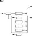
- Figure 1shows in an exemplary flow diagram a procedure of a method for generating a trajectory according to a preferred embodiment.
- at least one constraintis provided for generation of a set of initial waypoints (step 104) and also for the subsequent optimization of the trajectory (106).
- the at least one constraintfor instance comprises one or more obstacles, i.e. information about the at least one obstacle, such as their coordinates in a space, in which the trajectory shall be generated.
- the constraintmay optionally also comprise a maximum velocity and/or a maximum acceleration and/or a maximum jerk.
- the at least one constraintis required to be satisfied by the generated and/or optimized trajectory. That the at least one constraint is determined means for example that the predetermined constraint/s may be sent to the respective calculation module carrying out steps 104 and/or 106 or be retrieved by the respective calculation module.
- the generation of a set of initial waypoints in step 104serves the purpose of generating an initial geometric path from the predetermined starting point to the predetermined target point and may be carried out by a geometric path planner module.
- the trajectoryis optimized in step 106.
- the initial geometric pathi.e. the set of initial waypoints (step 108)
- a splineis generated by extending through the set of initial waypoints (step 110). Between each two of these waypoints, one spline extends, such that the splines are connected at the waypoints. This may occur for instance by means of a path generation module, wherein the spline may be generated for example as a quintic Bezier spline.
- the splineis sampled and a set of sample points is defined, which are located on the spline and preferably are spaced apart at a smaller distance than the distance between two adjacent waypoints. Afterwards, the sample points are interpolated to retrieve a trajectory continuously extending from the starting point to the target point (step 112). Afterwards, in step 114 the spline parameters are varied, preferably according to a resilient backpropagation (RPROP) optimization heuristics and a new iteration is started, including again the steps 110, 112 and 114, i.e. generating new splines based on the varied spline parameters, fitting a time-optimal trajectory, comparing it to the previous trajectory and eventually varying again the spline parameters.
- RPROPresilient backpropagation
- the trajectorycan be optimized by varying only three parameters.
- each initial waypoint calculated by the geometric path planner in step 104has three optimization parameters, which is the x-coordinate, the y-coordinate and the tangent of the spline at the coordinate of the respective sample points. Therefore, the calculation effort is greatly reduced as compared to conventional methods requiring a variation or optimization of a much larger number of variables. Shifting the position or coordinates of the sample points, possibly leads to an increase or a reduction of the path length. However, longer paths not necessarily need to be detrimental, since a longer path length might lead to a smoother path which possibly can be travelled with a higher speed while still satisfying certain constraints regarding a maximum acceleration and/or jerk.
- the methodmay use RPROP optimization heuristics, which are conventionally known in prior art, according to which each criteria is initially changed by a predetermined step size. For instance, if an improvement is observed due to a previous change or variation, the step size is increased for example by a factor of 1,2, if the result is worse, the optimization or variation direction is reversed and the step size is set for example to 0,5.
- the step sizeis the size of a variation step when varying the position of the sample points. This can be repeated until either the execution time is exceeded or the minimum step size is reached for each sample point.
- FIG. 2schematically shows a hardware- and software layout 200 of a control unit or a processing unit according a preferred embodiment.
- the layout 200shows a software module 202, which may be operated on a control unit for controlling a connected physical system 204, such as a displacement device or a transportation system comprising a mover 206.
- a connected physical system 204such as a displacement device or a transportation system comprising a mover 206.
- the software module 202includes a system controller 208, which determines and/or provides the start position and/or the target position and/or the at least one constraint, such as positions of obstacles and/or a maximum velocity and/or a maximum acceleration and/or a maximum jerk.
- the system controllerprovides the start position and/or the target position and/or the at least one constraint to the geometric path planner 210 for generating a set of initial waypoints and also to the trajectory optimization module 212 as an input for the optimization of a trajectory satisfying the at least one constraint based on the set of waypoints provided by the geometric path planner 210.
- the trajectoryis output as splines to a set point generator 214a within a motion controller system 214, which in turn controls the movement of the mover 206.
- an exemplary program codeis shown, which may carry out an optimization of the trajectory to a time-optimal trajectory.
- the algorithmis adjusted to finding the optimal path parameters ⁇ *, wherein ⁇ * denotes a vector of optimized coordinates of the sample points.
- the initial path parameteris denoted as ⁇ ini , the initial step size as ⁇ ini , the minimal step size ⁇ min , the maximum number of iterations N max and the at least one constraint as a vector C, which comprise at least a list of obstacles, such as their coordinates.
- the parameter hdenotes the vector of traveling times between the respective, adjacent waypoints and T the total traveling time along the whole trajectory.
- the lowered indices "ini”stand for “initial”, which means that this parameter is initially generated before the iterative optimization or provided as an input
- "mod”stands for "modified” parameters, which are varied or changed by the program code in the course of optimization
- the lowered index "i”denotes a single component of a vector-sized parameter, such as its component relating to one specific waypoint out of the vector of waypoints.
- the superscript index "*"denotes the (so far) optimized respective parameter.
- N Sdepicts the number of sample points, wherein N W depicts the number of waypoints.
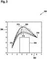
- Figure 3exemplarily shows in diagram 300 several different trajectories in a two-dimensional space, which are calculated by a method according to a preferred embodiment.
- the axis 302exemplarily illustrates an x-axis 302 and the axis 304 a y-axis.
- the object 306represents an obstacle, whose coordinates may be provided as a constraint, wherein the constraint might be that the trajectory may not collide with the obstacle or 306.
- the optimizationstarts with the initial trajectory 308 defined by the initial waypoints and a spline generated extending through the waypoints 316, wherein also the starting point 312 and the target point 314 are considered as waypoints 316.
- this initial trajectory 308is far from optimum, since it demands a long traveling path and in addition comprises a curve with a rather small radius of curvature, demanding a small velocity in order to limit the maximum acceleration in the curve.
- the time-optimized trajectory 310indicates the final, optimized trajectory after the optimization process, which appears more advantageous than the initial trajectory 308, since it demands a shorter traveling distance and exhibits a larger radius of curvature allowing higher velocities.
- the other trajectoriesrepresent (preliminary) trajectories, which have been calculated or generated during the optimization process, but have been discarded after a better suitable trajectory has been found. All trajectories extend from the starting point 312 to the target point 314.
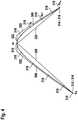
- Figure 4schematically depicts an exemplary time-optimized trajectory together with the initial waypoints 316 and several defined sample points 318.
- the starting point 312 and the target point 314are also used and/or defined as waypoints 316.
- an additional waypoint 316is generated between the starting point 312 and the target point 314, wherein the additional waypoint is denoted as w i .
- the calculated travelling times of the respective trajectoriesare calculated to be integer multiple of a predetermined control rate T s , which may represent a minimum time interval of temporally quantized system.
- T sa predetermined control rate
- the traveling time along the initial trajectory 308is calculated to be 606 times the control rate.
- the time-optimized trajectory 310requires a traveling time of only 512 times the control rate and, thus, can be travelled about 16% faster than the initial trajectory 308.
- the lines 320indicate a simple form of an initial suggestion for a trajectory connecting the waypoints 316.
- the initial trajectory 308is generated as splines based on the waypoints 316 and connected at the waypoints 312. This spline is then sampled to retrieve the sample points 318, which are then interpolated to form a trajectory. Subsequently, the trajectory 308 may be optimized by varying the spline parameters to achieve a time-optimized trajectory 310.
- the number of sample points 318may be larger than the number of waypoints 316.
- the time-optimized trajectory 310 and other trajectories emerging during the optimization processdo not necessarily extend through the (initial) waypoints 312, except the starting point 312 and the target point 314.
- the dashed linesindicate the tangents of the trajectory or spline at the waypoints 316.
Landscapes
- Engineering & Computer Science (AREA)
- Radar, Positioning & Navigation (AREA)
- Remote Sensing (AREA)
- Automation & Control Theory (AREA)
- Physics & Mathematics (AREA)
- General Physics & Mathematics (AREA)
- Manipulator (AREA)
Description
- The present invention relates to a method for generating a trajectory from a starting point to a target point based on at least one predetermined constraint, which the trajectory is required to satisfy. Furthermore, the invention relates to a processing unit and a control unit for a displacement device configured to carry out the method according to the invention. The invention relates to the technical field of displacement devices and of generating trajectories by means of a control unit for moving the displacement device and/or a transport system, in particular of planar displacement systems.
- Displacement devices typically use trajectory generation algorithms to provide trajectories for moving objects or parts of the displacement device from the starting point to a target point.
- The productivity of the transport system can be increased by decreasing the time of the transportations. However, a path for a trajectory being considered as optimal does not necessarily have to result in a time-optimal trajectory. Instead, a different path or trajectory requiring a longer travel time and/or distance may be preferred due to a limited amount of acceleration and/or jerk occurring in the displacement system as compared to a trajectory offering shorter travelling time. Regularly, in order to obtain such a time-optimal solution, different paths and/or trajectories have to be compared to retrieve the optimal solution.
- Some implementations are known in prior art, which are capable of calculating such trajectories, as disclosed for instance in M. Zucker, N. Ratli, A. D. Dragan, M. Pivtoraiko, M. Klingen-smith, C. M. Dellin, J. A. Bagnell and S. S.
- Srinivasa: "Chomp: Covariant Hamiltonian optimization for motion planning," The International Journal of Robotics Research, 2013;X. Lu, Y. Zhao, C. Wang and M. Tomizuka: "Trajectory planning for robot manipulators considering kinematic constraints using probabilistic roadmap approach," Journal of Dynamic Systems, Measurement, and Control, no. 130, 2017; and in documents
US20160207658A ;US20170179806A ; andUS9685849B2 - However, these trajectory generation algorithms demand a high computational effort and, thus, require a large computing power and/or a long computation time. This makes their implementation typically difficult, slow and/or expensive.
- Therefore, it is the objective technical problem of the invention to provide a method for generating a trajectory requiring less computational effort and by this to facilitate its implementation and/or to reduce the hardware requirements.
- ALESSANDRO GASPARETTO ET AL: "Trajectory Planning Robotics", MATHEMATICS IN COMPUTER SCIENCE; SP BIRKHA USER VERLAG BASEL, BASEL, discloses a method for trajectory planning by inputting a geometric path, kinematic and dynamic constraints and outputting a trajectory of joints, by specifying the path using a limited number of via-points and giving the solution by spline interpolation, expressing the trajectories by means of cubic splines.
- Bill Casselmann: "From Bezier to Bernstein", Feature Column from the American Mathematical Society, discloses the usage of Bezier curves in computer graphics.
- BOEHM ET AL: "ON DE CASTELJAUS ALGORITHM", COMPUTER AIDED GEOMETRIC DESIGN, discloses the optimization of a design curve by varying the angle of the tangent of the spline.
- Christian Igel and Michael Husken: "Improving the Rprop Learning Algorithm"; Proceedings of the Second ICSC International Symposium on Neural Computation, discloses that an optimization algorithm uses an RPROP heuristic.
- According to the invention, a method, a processing unit, a control unit, a displacement device, a computer program and a machine readable data storage medium having the features of the respective independent claim are disclosed. Preferred embodiments are subject-matter of the dependent claims and the following description.
- In one aspect the invention relates to a method for generating a trajectory from a starting point to a target point according to
claim 1. - In another aspect the invention relates to a processing unit configured to carry out a method according to the invention, and to a control unit for a displacement device comprising such a processing unit.
- In another aspect the invention relates to a displacement device comprising a control unit according to the invention. The displacement device is preferably configured as a transport system, most preferably as a planar motion system.
- A trajectory is to be understood as a path along which for instance a movement is to be carried out, for example by a displacement device and/or a tool. The waypoints may at least partially define the initial trajectory. The at least one constraint may be predetermined and may define one or more requirements, which the trajectory has to fulfil, to allow a movement along the trajectory satisfying predetermined requirements. Optionally, an initial velocity and/or an initial acceleration and/or an initial jerk may be predetermined and/or given. Determining the at least one constraint may include retrieving the at least one constraint, for instance from a user input and/or from a data storage. Preferably, the at least one constraint comprises a maximum velocity and/or a maximum acceleration and/or a maximum jerk allowed when traveling along the trajectory. Preferably, the at least one constraint may also comprise information about possible obstacles which need to be considered when generating the trajectory. Most preferably, the trajectory satisfies all requirements set out by the constraint, and in particular satisfies the maximum velocity and/or the maximum acceleration and/or the maximum jerk and prevents a collision with all obstacles defined by the at least one constraint.
- A spline is a mathematical function or curve, which is built-up from one or more polynomial functions. In particular a spline can comprise several spline segments, wherein according to the present invention preferably each waypoint and/or each traveling time interval is associated with one spline defined by a polynomial function segment and wherein all these spline segments together form a spline. A spline of n-th order comprises only spline segments, which are defined of a polynomial of maximum n-th order. Furthermore, requirements may be defined, in particular at the contact points at which adjacent spline segments are meeting each other, according to which the spline shall be continuously differentiable at least (n-1) times. In particular, a spline segment is defined by a coordinate, which is according to the present invention the at least one coordinate of the waypoint, a spline parameter and the distance between adjacent waypoints. In particular, the coordinate of the spline, i.e. the waypoint, is preferably defined by a pair of coordinates in two-dimensional space, for instance by an x-coordinate and a y-coordinate, which allows generating a two-dimensional trajectory in the two-dimensional space. For generating a spline and/or trajectory in a three-dimensional space, the waypoint may be defined by a triple of coordinates, such as an x-, a y- and a z-coordinate. The whole spline is defined by the concatenation of the individual spline segments.
- The trajectory is then formed by sampling the splines to obtain several sample points and by interpolating the several sample points to achieve a continuous trajectory.
- Optimizing the trajectory to a time-optimal trajectory means that the spline parameters of the splines forming the trajectory are varied and the trajectory is compared to the previous trajectory. If the variation of the trajectory results in an improved trajectory, i.e. a more time-optimal trajectory and/or a trajectory being better suited with regard to the constraint, the varied trajectory is taken over and possibly further optimized.
- The invention provides the advantage that the computational effort for generating and/or optimizing the trajectory can be reduced, because the number of variables that needs to be optimized and/or varied is greatly reduced when compared to conventional algorithms. Instead of conventional methods, the invention merely requires varying and/or optimizing the spline parameters, recalculating the splines on the basis of the varied spline parameters and rebuilding the trajectory on the basis of the varied splines. Therefore, the number of variables to be varied is greatly limited and, thus, the computational effort for the optimization of the trajectory is significantly reduced.
- Consequently, the invention provides the advantage, that the generation of the trajectory can be carried out on machines having moderate computational power and/or that the generation of the trajectory can be carried in a short amount of time, thus, speeding up the generation process. Alternatively or additionally, the invention may allow a large number of trajectory generations to be carried out in parallel by one control unit or machine.
- Furthermore, albeit the reduction in computational effort, the invention still allows constraints, in particular higher order constraints, such as a maximum velocity and/or a maximum acceleration and/or a maximum jerk, to be considered and by this to achieve a smooth trajectory minimizing the mechanical strain to the displacement system.
- Preferably, the spline is a quintic Bezier spline. This provides the advantage that a particularly smooth trajectory can be created with limited computational effort. This provides further the advantage that convex hull properties (CHP) can be used to increase the efficiency when checking for collisions of the trajectory with obstacles. An initial velocity and/or acceleration and/or jerk may be specified by using a quintic Bezier spline.
- According to the invention, the at least one constraint comprises a maximum velocity and/or a maximum acceleration and/or a maximum jerk occurring when traveling along the trajectory and/or the at least one constraint comprises alternatively or additionally a position of at least one obstacle, wherein the method, preferably in step c) and/or step d), comprises checking for a collision of the initial path and/or the trajectory with the position of the at least one obstacle. This allows an optimization or generation of the tra jectory ensuring that when traveling along the trajectory, collisions with obstacles defined by the constraints are avoided.
- According to the invention, varying the spline parameters includes varying at least one of the splines in its position and/or in an angle of a tangent, wherein the tangent defines a direction in which the spline extends at the position of respective waypoint. This allows a facilitated variation and/or optimization of the spline and, thus, of the trajectory with little computational effort. In particular, such an optimization of the trajectory requires only few variables to be modified or varied.
- According to the invention, varying the spline parameters includes a stepwise variation of the spline parameters in an iterative manner. This allows a facilitated implementation into a computer program and a step wise optimization of the trajectory. More preferably, a step size of the stepwise variation of the tangent is increased if the preceding variation improved the trajectory and/or wherein a step direction is reversed and the step size is reduced if the preceding variation impaired the trajectory. This allows a stepwise approach and/or a convergence to the time-optimal trajectory.
- Preferably, the optimizing of the trajectory to a time-optimal trajectory is performed by a RPROP optimization heuristic. The RPROP optimization heuristics allow a good efficiency and are simple in their implementation and use. Alternatively, a different gradient free optimization approach may be used, such like a Neader-Mead approach.
- Further advantages and embodiments of the invention will become apparent from the description and the appended figures.
- It should be noted that the previously mentioned features and the features to be further described in the following are usable not only in the respectively indicated combination, but also in further combinations or taken alone, without departing from the scope of the present invention, as defined by the appended claims.
- In the drawings:
Figure 1 shows in a flow diagram an exemplary procedure of a method for generating a trajectory according to a preferred embodiment.Figure 2 schematically shows a hardware- and software layout of a control unit or a processing unit according a preferred embodimentFigure 3 exemplarily shows in diagram several different trajectories.Figure 4 schematically depicts an exemplary time-optimized trajectory together with the initial waypoints and several defined sample points.Figure 1 shows in an exemplary flow diagram a procedure of a method for generating a trajectory according to a preferred embodiment. Instep 102, at least one constraint is provided for generation of a set of initial waypoints (step 104) and also for the subsequent optimization of the trajectory (106). The at least one constraint for instance comprises one or more obstacles, i.e. information about the at least one obstacle, such as their coordinates in a space, in which the trajectory shall be generated. Furthermore, the constraint may optionally also comprise a maximum velocity and/or a maximum acceleration and/or a maximum jerk. The at least one constraint is required to be satisfied by the generated and/or optimized trajectory. That the at least one constraint is determined means for example that the predetermined constraint/s may be sent to the respective calculation module carrying outsteps 104 and/or 106 or be retrieved by the respective calculation module.- The generation of a set of initial waypoints in
step 104 serves the purpose of generating an initial geometric path from the predetermined starting point to the predetermined target point and may be carried out by a geometric path planner module. - On the basis of the set of initial waypoints, which is handed over to a trajectory optimization module, the trajectory is optimized in
step 106. Having retrieved the initial geometric path, i.e. the set of initial waypoints (step 108), a spline is generated by extending through the set of initial waypoints (step 110). Between each two of these waypoints, one spline extends, such that the splines are connected at the waypoints. This may occur for instance by means of a path generation module, wherein the spline may be generated for example as a quintic Bezier spline. The spline is sampled and a set of sample points is defined, which are located on the spline and preferably are spaced apart at a smaller distance than the distance between two adjacent waypoints. Afterwards, the sample points are interpolated to retrieve a trajectory continuously extending from the starting point to the target point (step 112). Afterwards, instep 114 the spline parameters are varied, preferably according to a resilient backpropagation (RPROP) optimization heuristics and a new iteration is started, including again thesteps step 116. - According to this preferred embodiment using a quintic Bezier spline, the trajectory can be optimized by varying only three parameters. In other words, each initial waypoint calculated by the geometric path planner in
step 104 has three optimization parameters, which is the x-coordinate, the y-coordinate and the tangent of the spline at the coordinate of the respective sample points. Therefore, the calculation effort is greatly reduced as compared to conventional methods requiring a variation or optimization of a much larger number of variables. Shifting the position or coordinates of the sample points, possibly leads to an increase or a reduction of the path length. However, longer paths not necessarily need to be detrimental, since a longer path length might lead to a smoother path which possibly can be travelled with a higher speed while still satisfying certain constraints regarding a maximum acceleration and/or jerk. - In a preferred embodiment, the method may use RPROP optimization heuristics, which are conventionally known in prior art, according to which each criteria is initially changed by a predetermined step size. For instance, if an improvement is observed due to a previous change or variation, the step size is increased for example by a factor of 1,2, if the result is worse, the optimization or variation direction is reversed and the step size is set for example to 0,5. The step size is the size of a variation step when varying the position of the sample points. This can be repeated until either the execution time is exceeded or the minimum step size is reached for each sample point.
- Although good results can be achieved by means of RPROP optimization heuristics, also other optimization algorithms or systems may be used instead.
Figure 2 schematically shows a hardware- andsoftware layout 200 of a control unit or a processing unit according a preferred embodiment. Thelayout 200 shows asoftware module 202, which may be operated on a control unit for controlling a connectedphysical system 204, such as a displacement device or a transportation system comprising amover 206.- The
software module 202 includes asystem controller 208, which determines and/or provides the start position and/or the target position and/or the at least one constraint, such as positions of obstacles and/or a maximum velocity and/or a maximum acceleration and/or a maximum jerk. The system controller provides the start position and/or the target position and/or the at least one constraint to thegeometric path planner 210 for generating a set of initial waypoints and also to thetrajectory optimization module 212 as an input for the optimization of a trajectory satisfying the at least one constraint based on the set of waypoints provided by thegeometric path planner 210. - After completing the optimization of the trajectory, the trajectory is output as splines to a
set point generator 214a within amotion controller system 214, which in turn controls the movement of themover 206. - In the following, an exemplary program code is shown, which may carry out an optimization of the trajectory to a time-optimal trajectory. The algorithm is adjusted to finding the optimal path parametersΘ*, whereinΘ* denotes a vector of optimized coordinates of the sample points.
- The initial path parameter is denoted asΘini, the initial step size asΔΘini, the minimal step sizeΔΘmin, the maximum number of iterations Nmax and the at least one constraint as a vectorC, which comprise at least a list of obstacles, such as their coordinates.
- After finding the optimal trajectory, the optimized path parameter Θ* and the optimal trajectoryq*(t), which is a vector


- NS depicts the number of sample points, whereinNW depicts the number of waypoints.
Figure 3 exemplarily shows in diagram 300 several different trajectories in a two-dimensional space, which are calculated by a method according to a preferred embodiment. Theaxis 302 exemplarily illustrates anx-axis 302 and the axis 304 a y-axis. Theobject 306 represents an obstacle, whose coordinates may be provided as a constraint, wherein the constraint might be that the trajectory may not collide with the obstacle or 306.- The optimization starts with the
initial trajectory 308 defined by the initial waypoints and a spline generated extending through thewaypoints 316, wherein also thestarting point 312 and thetarget point 314 are considered aswaypoints 316. As can be seen, thisinitial trajectory 308 is far from optimum, since it demands a long traveling path and in addition comprises a curve with a rather small radius of curvature, demanding a small velocity in order to limit the maximum acceleration in the curve. The time-optimizedtrajectory 310 indicates the final, optimized trajectory after the optimization process, which appears more advantageous than theinitial trajectory 308, since it demands a shorter traveling distance and exhibits a larger radius of curvature allowing higher velocities. The other trajectories represent (preliminary) trajectories, which have been calculated or generated during the optimization process, but have been discarded after a better suitable trajectory has been found. All trajectories extend from thestarting point 312 to thetarget point 314. Figure 4 schematically depicts an exemplary time-optimized trajectory together with theinitial waypoints 316 and several defined sample points 318. Thestarting point 312 and thetarget point 314 are also used and/or defined aswaypoints 316. Furthermore, anadditional waypoint 316 is generated between thestarting point 312 and thetarget point 314, wherein the additional waypoint is denoted aswi.- The calculated travelling times of the respective trajectories are calculated to be integer multiple of a predetermined control rate Ts, which may represent a minimum time interval of temporally quantized system. The traveling time along the
initial trajectory 308 is calculated to be 606 times the control rate. In contrast, the time-optimizedtrajectory 310 requires a traveling time of only 512 times the control rate and, thus, can be travelled about 16% faster than theinitial trajectory 308. Thelines 320 indicate a simple form of an initial suggestion for a trajectory connecting thewaypoints 316. - The
initial trajectory 308 is generated as splines based on thewaypoints 316 and connected at thewaypoints 312. This spline is then sampled to retrieve thesample points 318, which are then interpolated to form a trajectory. Subsequently, thetrajectory 308 may be optimized by varying the spline parameters to achieve a time-optimizedtrajectory 310. The number ofsample points 318 may be larger than the number ofwaypoints 316. The time-optimizedtrajectory 310 and other trajectories emerging during the optimization process do not necessarily extend through the (initial)waypoints 312, except thestarting point 312 and thetarget point 314. - The dashed lines indicate the tangents of the trajectory or spline at the
waypoints 316.


Claims (10)
- Computer-implemented method for generating a trajectory (308) from a starting point (312) to a target point (314), the method comprising the steps:a) Determining at least one constraint, which the trajectory (308) is required to satisfy, wherein the at least one constraint comprises a maximum velocity and/or a maximum acceleration and/or a maximum jerk occurring when traveling along the trajectory, and/or wherein the at least one constraint comprises a position of at least one obstacle (306);b) Generating a set of initial waypoints (316) from the starting point (312) to the target point (314);c) Generating several splines based on associated spline parameters, wherein each of the splines extends between two adjacent waypoints (316) of the initial waypoints (316);d) Sampling the splines to generate sample points (318) and interpolating the sample points (318) to form a trajectory;e) Optimizing the trajectory (308) to a time-optimal trajectory (310), which satisfies the at least one constraint, by varying the spline parameters and comparing the required traveling time along the trajectory (310) after varying the spline parameters to the required traveling time before varying the spline parameters,characterized in that varying the spline parameters includes varying an angle of a tangent, wherein the tangent defines a direction in which the spline extends at the respective waypoint (316), wherein varying the splines includes a stepwise variation of the angle of the tangent of the respective splines in an iterative manner, wherein a step size of the stepwise variation is increased, if the preceding variation improved the trajectory and/or wherein a step direction is reversed and the step size is reduced, if the preceding variation impaired the trajectory.
- Method according to claim 1, wherein the spline is a quintic Bezier spline.
- Method according to any one of the preceding claims, wherein the at least one constraint comprises a position of at least one obstacle (306) and wherein the method, in step c) and/or step d), comprises checking for a collision of the trajectory (310) with the position of the at least one obstacle.
- Method according to any one of the preceding claims, wherein the optimization of the trajectory to a time-optimal trajectory (310) is ended if the step size reaches or falls below a predetermined threshold step size and/or if a predetermined planning time elapsed.
- Method according to any one of the preceding claims, wherein the optimizing of the trajectory (308) to a time-optimal trajectory (310) is performed by a resilient backpropagation (RPROP) optimization heuristic.
- Processing unit configured to carry out a method according to any one of the preceding claims.
- Control unit for a displacement device, comprising a processing unit according to claim 6.
- Displacement device comprising a control unit according to claim 7.
- Computer program configured to cause a processing unit carrying out a method according to any one of the claims 1 to 5.
- Machine readable data storage medium having a computer program according to claim 9 stored thereon.
Priority Applications (1)
| Application Number | Priority Date | Filing Date | Title |
|---|---|---|---|
| EP17202490.3AEP3486612B1 (en) | 2017-11-20 | 2017-11-20 | Method for generating a trajectory |
Applications Claiming Priority (1)
| Application Number | Priority Date | Filing Date | Title |
|---|---|---|---|
| EP17202490.3AEP3486612B1 (en) | 2017-11-20 | 2017-11-20 | Method for generating a trajectory |
Publications (2)
| Publication Number | Publication Date |
|---|---|
| EP3486612A1 EP3486612A1 (en) | 2019-05-22 |
| EP3486612B1true EP3486612B1 (en) | 2020-07-01 |
Family
ID=60421606
Family Applications (1)
| Application Number | Title | Priority Date | Filing Date |
|---|---|---|---|
| EP17202490.3AActiveEP3486612B1 (en) | 2017-11-20 | 2017-11-20 | Method for generating a trajectory |
Country Status (1)
| Country | Link |
|---|---|
| EP (1) | EP3486612B1 (en) |
Families Citing this family (14)
| Publication number | Priority date | Publication date | Assignee | Title |
|---|---|---|---|---|
| EP3449214B1 (en) | 2016-06-10 | 2021-12-15 | Duke University | Motion planning for autonomous vehicles and reconfigurable motion planning processors |
| WO2019139815A1 (en) | 2018-01-12 | 2019-07-18 | Duke University | Apparatus, method and article to facilitate motion planning of an autonomous vehicle in an environment having dynamic objects |
| TWI822729B (en) | 2018-02-06 | 2023-11-21 | 美商即時機器人股份有限公司 | Method and apparatus for motion planning of a robot storing a discretized environment on one or more processors and improved operation of same |
| EP3769174B1 (en) | 2018-03-21 | 2022-07-06 | Realtime Robotics, Inc. | Motion planning of a robot for various environments and tasks and improved operation of same |
| WO2020040979A1 (en) | 2018-08-23 | 2020-02-27 | Realtime Robotics, Inc. | Collision detection useful in motion planning for robotics |
| US12204336B2 (en) | 2018-12-04 | 2025-01-21 | Duke University | Apparatus, method and article to facilitate motion planning in an environment having dynamic objects |
| CN113905855B (en) | 2019-04-17 | 2023-08-25 | 实时机器人有限公司 | Motion planning graph generation user interface, system, method and rules |
| EP3993963B1 (en)* | 2019-08-23 | 2025-07-16 | Realtime Robotics, Inc. | Motion planning for robots to optimize velocity while maintaining limits on acceleration and jerk |
| TWI887329B (en) | 2020-01-22 | 2025-06-21 | 美商即時機器人股份有限公司 | Method and system for configuration of robots in multi-robot operational environment |
| CN115297999A (en) | 2020-03-18 | 2022-11-04 | 实时机器人有限公司 | A digital representation of the robot operating environment useful in the motion planning of robots |
| FR3117207B1 (en)* | 2020-12-04 | 2022-12-09 | Thales Sa | Path calculation method and device for a mobile platform |
| CN116678430B (en)* | 2023-05-23 | 2024-03-19 | 北京爱好科技有限公司 | Driving track determining method and device, electronic equipment and readable storage medium |
| CN117553801B (en)* | 2024-01-08 | 2024-07-26 | 深圳市普渡科技有限公司 | Topological path map generation method, device, robot and storage medium |
| CN119779268A (en)* | 2024-12-24 | 2025-04-08 | 中国航空工业集团公司西安飞行自动控制研究所 | A method and device for extracting vector trajectory information from an elevation terrain scanning area |
Family Cites Families (3)
| Publication number | Priority date | Publication date | Assignee | Title |
|---|---|---|---|---|
| EP4033645A1 (en) | 2011-10-27 | 2022-07-27 | The University of British Columbia | Displacement devices and methods for fabrication, use and control of same |
| WO2015184553A1 (en) | 2014-06-07 | 2015-12-10 | The University Of British Columbia | Methods and systems for controllably moving multiple moveable stages in a displacement device |
| ES2637746T3 (en) | 2015-01-19 | 2017-10-16 | Cama1 S.P.A. | A packing machine with a magnetic impeller conveyor |
- 2017
- 2017-11-20EPEP17202490.3Apatent/EP3486612B1/enactiveActive
Non-Patent Citations (1)
| Title |
|---|
| None* |
Also Published As
| Publication number | Publication date |
|---|---|
| EP3486612A1 (en) | 2019-05-22 |
Similar Documents
| Publication | Publication Date | Title |
|---|---|---|
| EP3486612B1 (en) | Method for generating a trajectory | |
| EP3623759B1 (en) | A computer-implemented method and a system for defining a path for a vehicle within an environment with obstacles | |
| EP4180894B1 (en) | Method and device for planning obstacle avoidance path for traveling device | |
| Zhang et al. | Optimal vehicle path planning using quadratic optimization for baidu apollo open platform | |
| EP3993963B1 (en) | Motion planning for robots to optimize velocity while maintaining limits on acceleration and jerk | |
| JP3593850B2 (en) | Tool point sequence generation method | |
| CN111830979B (en) | Track optimization method and device | |
| CN101493687B (en) | NURBS curve self-adaptive subsection interpolation method for real-time forward-looking full acceleration and deceleration control | |
| Magid et al. | Spline-based robot navigation | |
| EP3885867A1 (en) | Method and system for controlling autonomous or semi-autonomous vehicle | |
| Heiden et al. | Gradient-informed path smoothing for wheeled mobile robots | |
| CN105710881A (en) | Continuous trajectory planning transition method for robot tail end | |
| CN104933228A (en) | Unmanned ground vehicle real-time track planning method based on speed impediment | |
| JP2003241836A (en) | Method and apparatus for controlling self-propelled moving object | |
| KR101056600B1 (en) | Industrial Product Design Method Using Closoid Curve and Numerical Control Method and Apparatus Using Industrial Product Designed by Two Design Method | |
| EP3685968B1 (en) | Robot motion planning in manufacturing | |
| JP4518033B2 (en) | Route creation method, moving body, and moving body control system | |
| KR102552719B1 (en) | Method and apparatus for automatically generating drive route | |
| Yu et al. | Hierarchical framework integrating rapidly-exploring random tree with deep reinforcement learning for autonomous vehicle | |
| Leu et al. | Long-horizon motion planning via sampling and segmented trajectory optimization | |
| Zhong et al. | Efficiency-optimized path planning algorithm for car-like mobile robots in bilateral constraint corridor environments | |
| Hsu et al. | Design of smooth path based on the conversion between η 3 spline and Bezier curve | |
| Wu et al. | Time‐Optimal Trajectory Planning along Parametric Polynomial Lane‐Change Curves with Bounded Velocity and Acceleration: Simulations for a Unicycle Based on Numerical Integration | |
| CN118617407A (en) | A robot arm trajectory blending control method and device | |
| Brembeck et al. | Real-time capable path planning for energy management systems in future vehicle architectures |
Legal Events
| Date | Code | Title | Description |
|---|---|---|---|
| PUAI | Public reference made under article 153(3) epc to a published international application that has entered the european phase | Free format text:ORIGINAL CODE: 0009012 | |
| STAA | Information on the status of an ep patent application or granted ep patent | Free format text:STATUS: THE APPLICATION HAS BEEN PUBLISHED | |
| AK | Designated contracting states | Kind code of ref document:A1 Designated state(s):AL AT BE BG CH CY CZ DE DK EE ES FI FR GB GR HR HU IE IS IT LI LT LU LV MC MK MT NL NO PL PT RO RS SE SI SK SM TR | |
| AX | Request for extension of the european patent | Extension state:BA ME | |
| STAA | Information on the status of an ep patent application or granted ep patent | Free format text:STATUS: REQUEST FOR EXAMINATION WAS MADE | |
| 17P | Request for examination filed | Effective date:20191122 | |
| RBV | Designated contracting states (corrected) | Designated state(s):AL AT BE BG CH CY CZ DE DK EE ES FI FR GB GR HR HU IE IS IT LI LT LU LV MC MK MT NL NO PL PT RO RS SE SI SK SM TR | |
| RIC1 | Information provided on ipc code assigned before grant | Ipc:G01C 21/20 20060101AFI20191205BHEP | |
| GRAP | Despatch of communication of intention to grant a patent | Free format text:ORIGINAL CODE: EPIDOSNIGR1 | |
| STAA | Information on the status of an ep patent application or granted ep patent | Free format text:STATUS: GRANT OF PATENT IS INTENDED | |
| RIC1 | Information provided on ipc code assigned before grant | Ipc:G01C 21/20 20060101AFI20200319BHEP Ipc:G01C 21/34 20060101ALI20200319BHEP | |
| RAP1 | Party data changed (applicant data changed or rights of an application transferred) | Owner name:ROBERT BOSCH GMBH | |
| INTG | Intention to grant announced | Effective date:20200416 | |
| GRAS | Grant fee paid | Free format text:ORIGINAL CODE: EPIDOSNIGR3 | |
| GRAA | (expected) grant | Free format text:ORIGINAL CODE: 0009210 | |
| STAA | Information on the status of an ep patent application or granted ep patent | Free format text:STATUS: THE PATENT HAS BEEN GRANTED | |
| AK | Designated contracting states | Kind code of ref document:B1 Designated state(s):AL AT BE BG CH CY CZ DE DK EE ES FI FR GB GR HR HU IE IS IT LI LT LU LV MC MK MT NL NO PL PT RO RS SE SI SK SM TR | |
| REG | Reference to a national code | Ref country code:CH Ref legal event code:EP Ref country code:AT Ref legal event code:REF Ref document number:1286582 Country of ref document:AT Kind code of ref document:T Effective date:20200715 | |
| REG | Reference to a national code | Ref country code:IE Ref legal event code:FG4D | |
| REG | Reference to a national code | Ref country code:DE Ref legal event code:R096 Ref document number:602017018947 Country of ref document:DE | |
| REG | Reference to a national code | Ref country code:LT Ref legal event code:MG4D | |
| PG25 | Lapsed in a contracting state [announced via postgrant information from national office to epo] | Ref country code:BG Free format text:LAPSE BECAUSE OF FAILURE TO SUBMIT A TRANSLATION OF THE DESCRIPTION OR TO PAY THE FEE WITHIN THE PRESCRIBED TIME-LIMIT Effective date:20201001 | |
| REG | Reference to a national code | Ref country code:NL Ref legal event code:MP Effective date:20200701 | |
| REG | Reference to a national code | Ref country code:AT Ref legal event code:MK05 Ref document number:1286582 Country of ref document:AT Kind code of ref document:T Effective date:20200701 | |
| PG25 | Lapsed in a contracting state [announced via postgrant information from national office to epo] | Ref country code:ES Free format text:LAPSE BECAUSE OF FAILURE TO SUBMIT A TRANSLATION OF THE DESCRIPTION OR TO PAY THE FEE WITHIN THE PRESCRIBED TIME-LIMIT Effective date:20200701 Ref country code:CZ Free format text:LAPSE BECAUSE OF FAILURE TO SUBMIT A TRANSLATION OF THE DESCRIPTION OR TO PAY THE FEE WITHIN THE PRESCRIBED TIME-LIMIT Effective date:20200701 Ref country code:PT Free format text:LAPSE BECAUSE OF FAILURE TO SUBMIT A TRANSLATION OF THE DESCRIPTION OR TO PAY THE FEE WITHIN THE PRESCRIBED TIME-LIMIT Effective date:20201102 Ref country code:LT Free format text:LAPSE BECAUSE OF FAILURE TO SUBMIT A TRANSLATION OF THE DESCRIPTION OR TO PAY THE FEE WITHIN THE PRESCRIBED TIME-LIMIT Effective date:20200701 Ref country code:HR Free format text:LAPSE BECAUSE OF FAILURE TO SUBMIT A TRANSLATION OF THE DESCRIPTION OR TO PAY THE FEE WITHIN THE PRESCRIBED TIME-LIMIT Effective date:20200701 Ref country code:AT Free format text:LAPSE BECAUSE OF FAILURE TO SUBMIT A TRANSLATION OF THE DESCRIPTION OR TO PAY THE FEE WITHIN THE PRESCRIBED TIME-LIMIT Effective date:20200701 Ref country code:GR Free format text:LAPSE BECAUSE OF FAILURE TO SUBMIT A TRANSLATION OF THE DESCRIPTION OR TO PAY THE FEE WITHIN THE PRESCRIBED TIME-LIMIT Effective date:20201002 Ref country code:NO Free format text:LAPSE BECAUSE OF FAILURE TO SUBMIT A TRANSLATION OF THE DESCRIPTION OR TO PAY THE FEE WITHIN THE PRESCRIBED TIME-LIMIT Effective date:20201001 Ref country code:FI Free format text:LAPSE BECAUSE OF FAILURE TO SUBMIT A TRANSLATION OF THE DESCRIPTION OR TO PAY THE FEE WITHIN THE PRESCRIBED TIME-LIMIT Effective date:20200701 Ref country code:SE Free format text:LAPSE BECAUSE OF FAILURE TO SUBMIT A TRANSLATION OF THE DESCRIPTION OR TO PAY THE FEE WITHIN THE PRESCRIBED TIME-LIMIT Effective date:20200701 | |
| PG25 | Lapsed in a contracting state [announced via postgrant information from national office to epo] | Ref country code:RS Free format text:LAPSE BECAUSE OF FAILURE TO SUBMIT A TRANSLATION OF THE DESCRIPTION OR TO PAY THE FEE WITHIN THE PRESCRIBED TIME-LIMIT Effective date:20200701 Ref country code:PL Free format text:LAPSE BECAUSE OF FAILURE TO SUBMIT A TRANSLATION OF THE DESCRIPTION OR TO PAY THE FEE WITHIN THE PRESCRIBED TIME-LIMIT Effective date:20200701 Ref country code:LV Free format text:LAPSE BECAUSE OF FAILURE TO SUBMIT A TRANSLATION OF THE DESCRIPTION OR TO PAY THE FEE WITHIN THE PRESCRIBED TIME-LIMIT Effective date:20200701 Ref country code:IS Free format text:LAPSE BECAUSE OF FAILURE TO SUBMIT A TRANSLATION OF THE DESCRIPTION OR TO PAY THE FEE WITHIN THE PRESCRIBED TIME-LIMIT Effective date:20201101 | |
| PG25 | Lapsed in a contracting state [announced via postgrant information from national office to epo] | Ref country code:NL Free format text:LAPSE BECAUSE OF FAILURE TO SUBMIT A TRANSLATION OF THE DESCRIPTION OR TO PAY THE FEE WITHIN THE PRESCRIBED TIME-LIMIT Effective date:20200701 | |
| REG | Reference to a national code | Ref country code:DE Ref legal event code:R097 Ref document number:602017018947 Country of ref document:DE | |
| PG25 | Lapsed in a contracting state [announced via postgrant information from national office to epo] | Ref country code:EE Free format text:LAPSE BECAUSE OF FAILURE TO SUBMIT A TRANSLATION OF THE DESCRIPTION OR TO PAY THE FEE WITHIN THE PRESCRIBED TIME-LIMIT Effective date:20200701 Ref country code:IT Free format text:LAPSE BECAUSE OF FAILURE TO SUBMIT A TRANSLATION OF THE DESCRIPTION OR TO PAY THE FEE WITHIN THE PRESCRIBED TIME-LIMIT Effective date:20200701 Ref country code:SM Free format text:LAPSE BECAUSE OF FAILURE TO SUBMIT A TRANSLATION OF THE DESCRIPTION OR TO PAY THE FEE WITHIN THE PRESCRIBED TIME-LIMIT Effective date:20200701 Ref country code:RO Free format text:LAPSE BECAUSE OF FAILURE TO SUBMIT A TRANSLATION OF THE DESCRIPTION OR TO PAY THE FEE WITHIN THE PRESCRIBED TIME-LIMIT Effective date:20200701 Ref country code:DK Free format text:LAPSE BECAUSE OF FAILURE TO SUBMIT A TRANSLATION OF THE DESCRIPTION OR TO PAY THE FEE WITHIN THE PRESCRIBED TIME-LIMIT Effective date:20200701 | |
| PLBE | No opposition filed within time limit | Free format text:ORIGINAL CODE: 0009261 | |
| STAA | Information on the status of an ep patent application or granted ep patent | Free format text:STATUS: NO OPPOSITION FILED WITHIN TIME LIMIT | |
| PG25 | Lapsed in a contracting state [announced via postgrant information from national office to epo] | Ref country code:AL Free format text:LAPSE BECAUSE OF FAILURE TO SUBMIT A TRANSLATION OF THE DESCRIPTION OR TO PAY THE FEE WITHIN THE PRESCRIBED TIME-LIMIT Effective date:20200701 | |
| 26N | No opposition filed | Effective date:20210406 | |
| PG25 | Lapsed in a contracting state [announced via postgrant information from national office to epo] | Ref country code:MC Free format text:LAPSE BECAUSE OF FAILURE TO SUBMIT A TRANSLATION OF THE DESCRIPTION OR TO PAY THE FEE WITHIN THE PRESCRIBED TIME-LIMIT Effective date:20200701 Ref country code:SK Free format text:LAPSE BECAUSE OF FAILURE TO SUBMIT A TRANSLATION OF THE DESCRIPTION OR TO PAY THE FEE WITHIN THE PRESCRIBED TIME-LIMIT Effective date:20200701 | |
| REG | Reference to a national code | Ref country code:CH Ref legal event code:PL | |
| PG25 | Lapsed in a contracting state [announced via postgrant information from national office to epo] | Ref country code:LU Free format text:LAPSE BECAUSE OF NON-PAYMENT OF DUE FEES Effective date:20201120 | |
| REG | Reference to a national code | Ref country code:BE Ref legal event code:MM Effective date:20201130 | |
| PG25 | Lapsed in a contracting state [announced via postgrant information from national office to epo] | Ref country code:SI Free format text:LAPSE BECAUSE OF FAILURE TO SUBMIT A TRANSLATION OF THE DESCRIPTION OR TO PAY THE FEE WITHIN THE PRESCRIBED TIME-LIMIT Effective date:20200701 Ref country code:LI Free format text:LAPSE BECAUSE OF NON-PAYMENT OF DUE FEES Effective date:20201130 Ref country code:CH Free format text:LAPSE BECAUSE OF NON-PAYMENT OF DUE FEES Effective date:20201130 | |
| PG25 | Lapsed in a contracting state [announced via postgrant information from national office to epo] | Ref country code:IE Free format text:LAPSE BECAUSE OF NON-PAYMENT OF DUE FEES Effective date:20201120 Ref country code:FR Free format text:LAPSE BECAUSE OF NON-PAYMENT OF DUE FEES Effective date:20201130 | |
| PG25 | Lapsed in a contracting state [announced via postgrant information from national office to epo] | Ref country code:TR Free format text:LAPSE BECAUSE OF FAILURE TO SUBMIT A TRANSLATION OF THE DESCRIPTION OR TO PAY THE FEE WITHIN THE PRESCRIBED TIME-LIMIT Effective date:20200701 Ref country code:MT Free format text:LAPSE BECAUSE OF FAILURE TO SUBMIT A TRANSLATION OF THE DESCRIPTION OR TO PAY THE FEE WITHIN THE PRESCRIBED TIME-LIMIT Effective date:20200701 Ref country code:CY Free format text:LAPSE BECAUSE OF FAILURE TO SUBMIT A TRANSLATION OF THE DESCRIPTION OR TO PAY THE FEE WITHIN THE PRESCRIBED TIME-LIMIT Effective date:20200701 | |
| PG25 | Lapsed in a contracting state [announced via postgrant information from national office to epo] | Ref country code:MK Free format text:LAPSE BECAUSE OF FAILURE TO SUBMIT A TRANSLATION OF THE DESCRIPTION OR TO PAY THE FEE WITHIN THE PRESCRIBED TIME-LIMIT Effective date:20200701 | |
| GBPC | Gb: european patent ceased through non-payment of renewal fee | Effective date:20211120 | |
| PG25 | Lapsed in a contracting state [announced via postgrant information from national office to epo] | Ref country code:BE Free format text:LAPSE BECAUSE OF NON-PAYMENT OF DUE FEES Effective date:20201130 | |
| PG25 | Lapsed in a contracting state [announced via postgrant information from national office to epo] | Ref country code:GB Free format text:LAPSE BECAUSE OF NON-PAYMENT OF DUE FEES Effective date:20211120 | |
| PGFP | Annual fee paid to national office [announced via postgrant information from national office to epo] | Ref country code:DE Payment date:20250122 Year of fee payment:8 |