EP3485820A1 - Magnetic wound closure device - Google Patents
Magnetic wound closure deviceDownload PDFInfo
- Publication number
- EP3485820A1 EP3485820A1EP18213883.4AEP18213883AEP3485820A1EP 3485820 A1EP3485820 A1EP 3485820A1EP 18213883 AEP18213883 AEP 18213883AEP 3485820 A1EP3485820 A1EP 3485820A1
- Authority
- EP
- European Patent Office
- Prior art keywords
- magnet
- inner edge
- magnets
- removable sheet
- closure device
- Prior art date
- Legal status (The legal status is an assumption and is not a legal conclusion. Google has not performed a legal analysis and makes no representation as to the accuracy of the status listed.)
- Granted
Links
- 230000005291magnetic effectEffects0.000titleclaimsdescription46
- 238000005192partitionMethods0.000claimsabstractdescription37
- 239000012790adhesive layerSubstances0.000claimsdescription15
- 229920000642polymerPolymers0.000claimsdescription11
- 229910001172neodymium magnetInorganic materials0.000claimsdescription5
- 230000001681protective effectEffects0.000claimsdescription4
- 208000027418Wounds and injuryDiseases0.000description121
- 206010052428WoundDiseases0.000description120
- 238000000034methodMethods0.000description24
- 239000000853adhesiveSubstances0.000description17
- 230000001070adhesive effectEffects0.000description17
- 239000010410layerSubstances0.000description11
- 230000029663wound healingEffects0.000description11
- 239000000696magnetic materialSubstances0.000description7
- 239000000463materialSubstances0.000description7
- UQSXHKLRYXJYBZ-UHFFFAOYSA-NIron oxideChemical compound[Fe]=OUQSXHKLRYXJYBZ-UHFFFAOYSA-N0.000description6
- 239000003292glueSubstances0.000description6
- 208000014674injuryDiseases0.000description6
- 210000001519tissueAnatomy0.000description6
- 230000035876healingEffects0.000description5
- 239000006247magnetic powderSubstances0.000description5
- 229920001651CyanoacrylatePolymers0.000description4
- MWCLLHOVUTZFKS-UHFFFAOYSA-NMethyl cyanoacrylateChemical compoundCOC(=O)C(=C)C#NMWCLLHOVUTZFKS-UHFFFAOYSA-N0.000description4
- 230000000295complement effectEffects0.000description4
- 239000004014plasticizerSubstances0.000description4
- -1polyethylenePolymers0.000description4
- 239000000843powderSubstances0.000description4
- 230000035752proliferative phaseEffects0.000description4
- 230000008733traumaEffects0.000description4
- 239000004709Chlorinated polyethyleneSubstances0.000description3
- XEEYBQQBJWHFJM-UHFFFAOYSA-NIronChemical compound[Fe]XEEYBQQBJWHFJM-UHFFFAOYSA-N0.000description3
- SZVJSHCCFOBDDC-UHFFFAOYSA-Niron(II,III) oxideInorganic materialsO=[Fe]O[Fe]O[Fe]=OSZVJSHCCFOBDDC-UHFFFAOYSA-N0.000description3
- 239000000203mixtureSubstances0.000description3
- 229920003023plasticPolymers0.000description3
- 239000004033plasticSubstances0.000description3
- 229910052761rare earth metalInorganic materials0.000description3
- 230000037390scarringEffects0.000description3
- 208000034693LacerationDiseases0.000description2
- 239000004698PolyethyleneSubstances0.000description2
- BJQHLKABXJIVAM-UHFFFAOYSA-Nbis(2-ethylhexyl) phthalateChemical compoundCCCCC(CC)COC(=O)C1=CC=CC=C1C(=O)OCC(CC)CCCCBJQHLKABXJIVAM-UHFFFAOYSA-N0.000description2
- 239000003795chemical substances by applicationSubstances0.000description2
- 230000006378damageEffects0.000description2
- DOIRQSBPFJWKBE-UHFFFAOYSA-Ndibutyl phthalateChemical compoundCCCCOC(=O)C1=CC=CC=C1C(=O)OCCCCDOIRQSBPFJWKBE-UHFFFAOYSA-N0.000description2
- 229920001971elastomerPolymers0.000description2
- 230000023597hemostasisEffects0.000description2
- 230000002757inflammatory effectEffects0.000description2
- 238000004519manufacturing processMethods0.000description2
- 244000052769pathogenSpecies0.000description2
- 229920000573polyethylenePolymers0.000description2
- 229920001296polysiloxanePolymers0.000description2
- 150000002910rare earth metalsChemical class0.000description2
- 238000007634remodelingMethods0.000description2
- 231100000331toxicToxicity0.000description2
- 230000002588toxic effectEffects0.000description2
- 230000010388wound contractionEffects0.000description2
- SIXWIUJQBBANGK-UHFFFAOYSA-N4-(4-fluorophenyl)-1h-pyrazol-5-amineChemical compoundN1N=CC(C=2C=CC(F)=CC=2)=C1NSIXWIUJQBBANGK-UHFFFAOYSA-N0.000description1
- 229910000521B alloyInorganic materials0.000description1
- 208000035143Bacterial infectionDiseases0.000description1
- ZOXJGFHDIHLPTG-UHFFFAOYSA-NBoronChemical compound[B]ZOXJGFHDIHLPTG-UHFFFAOYSA-N0.000description1
- 206010053567CoagulopathiesDiseases0.000description1
- 102000008186CollagenHuman genes0.000description1
- 108010035532CollagenProteins0.000description1
- 239000004821Contact adhesiveSubstances0.000description1
- 229910052692DysprosiumInorganic materials0.000description1
- 239000004593EpoxySubstances0.000description1
- 229910000640Fe alloyInorganic materials0.000description1
- 206010020751HypersensitivityDiseases0.000description1
- 229910000583Nd alloyInorganic materials0.000description1
- 239000004677NylonSubstances0.000description1
- 239000004743PolypropyleneSubstances0.000description1
- 239000004793PolystyreneSubstances0.000description1
- 239000004820Pressure-sensitive adhesiveSubstances0.000description1
- 208000031074ReinjuryDiseases0.000description1
- 241000405217Viola <butterfly>Species0.000description1
- 238000005299abrasionMethods0.000description1
- 239000002250absorbentSubstances0.000description1
- 230000002745absorbentEffects0.000description1
- NIXOWILDQLNWCW-UHFFFAOYSA-Nacrylic acid groupChemical groupC(C=C)(=O)ONIXOWILDQLNWCW-UHFFFAOYSA-N0.000description1
- 208000030961allergic reactionDiseases0.000description1
- 230000003444anaesthetic effectEffects0.000description1
- 210000003484anatomyAnatomy0.000description1
- 208000022362bacterial infectious diseaseDiseases0.000description1
- 230000003851biochemical processEffects0.000description1
- 239000003181biological factorSubstances0.000description1
- 230000015572biosynthetic processEffects0.000description1
- 230000000740bleeding effectEffects0.000description1
- 210000004204blood vesselAnatomy0.000description1
- 229910052796boronInorganic materials0.000description1
- 239000006227byproductSubstances0.000description1
- 210000004027cellAnatomy0.000description1
- 230000035602clottingEffects0.000description1
- 229920001436collagenPolymers0.000description1
- 230000008602contractionEffects0.000description1
- 230000003111delayed effectEffects0.000description1
- 230000000694effectsEffects0.000description1
- 239000000806elastomerSubstances0.000description1
- 210000002919epithelial cellAnatomy0.000description1
- 125000003700epoxy groupChemical group0.000description1
- 150000002148estersChemical class0.000description1
- 239000003302ferromagnetic materialSubstances0.000description1
- 239000000835fiberSubstances0.000description1
- 239000012530fluidSubstances0.000description1
- 230000009477glass transitionEffects0.000description1
- 239000008187granular materialSubstances0.000description1
- 230000037313granulation tissue formationEffects0.000description1
- 208000015181infectious diseaseDiseases0.000description1
- 239000007924injectionSubstances0.000description1
- 238000002347injectionMethods0.000description1
- 238000007689inspectionMethods0.000description1
- 238000009413insulationMethods0.000description1
- 229910052742ironInorganic materials0.000description1
- 239000004816latexSubstances0.000description1
- 229920000126latexPolymers0.000description1
- 238000002690local anesthesiaMethods0.000description1
- 210000000651myofibroblastAnatomy0.000description1
- 229920005615natural polymerPolymers0.000description1
- QEFYFXOXNSNQGX-UHFFFAOYSA-Nneodymium atomChemical compound[Nd]QEFYFXOXNSNQGX-UHFFFAOYSA-N0.000description1
- 150000002825nitrilesChemical class0.000description1
- 231100000252nontoxicToxicity0.000description1
- 230000003000nontoxic effectEffects0.000description1
- 229920001778nylonPolymers0.000description1
- AJCDFVKYMIUXCR-UHFFFAOYSA-Noxobarium;oxo(oxoferriooxy)ironChemical compound[Ba]=O.O=[Fe]O[Fe]=O.O=[Fe]O[Fe]=O.O=[Fe]O[Fe]=O.O=[Fe]O[Fe]=O.O=[Fe]O[Fe]=O.O=[Fe]O[Fe]=OAJCDFVKYMIUXCR-UHFFFAOYSA-N0.000description1
- 239000002245particleSubstances0.000description1
- 230000035515penetrationEffects0.000description1
- 229920001084poly(chloroprene)Polymers0.000description1
- 229920002037poly(vinyl butyral) polymerPolymers0.000description1
- 229920002239polyacrylonitrilePolymers0.000description1
- 229920000647polyepoxidePolymers0.000description1
- 229920000728polyesterPolymers0.000description1
- 229920000098polyolefinPolymers0.000description1
- 229920001155polypropylenePolymers0.000description1
- 229920002223polystyrenePolymers0.000description1
- 239000004814polyurethaneSubstances0.000description1
- 229920002635polyurethanePolymers0.000description1
- 239000004800polyvinyl chlorideSubstances0.000description1
- 229920000915polyvinyl chloridePolymers0.000description1
- 239000012254powdered materialSubstances0.000description1
- 229920005989resinPolymers0.000description1
- 239000011347resinSubstances0.000description1
- 239000007787solidSubstances0.000description1
- 235000012424soybean oilNutrition0.000description1
- 239000003549soybean oilSubstances0.000description1
- 229910052712strontiumInorganic materials0.000description1
- CIOAGBVUUVVLOB-UHFFFAOYSA-Nstrontium atomChemical compound[Sr]CIOAGBVUUVVLOB-UHFFFAOYSA-N0.000description1
- 229920001059synthetic polymerPolymers0.000description1
- 229920001169thermoplasticPolymers0.000description1
- 239000004416thermosoftening plasticSubstances0.000description1
- 229920002554vinyl polymerPolymers0.000description1
- 229910000859α-FeInorganic materials0.000description1
Images


Classifications
- A—HUMAN NECESSITIES
- A61—MEDICAL OR VETERINARY SCIENCE; HYGIENE
- A61B—DIAGNOSIS; SURGERY; IDENTIFICATION
- A61B17/00—Surgical instruments, devices or methods
- A61B17/08—Wound clamps or clips, i.e. not or only partly penetrating the tissue ; Devices for bringing together the edges of a wound
- A—HUMAN NECESSITIES
- A61—MEDICAL OR VETERINARY SCIENCE; HYGIENE
- A61B—DIAGNOSIS; SURGERY; IDENTIFICATION
- A61B17/00—Surgical instruments, devices or methods
- A61B17/08—Wound clamps or clips, i.e. not or only partly penetrating the tissue ; Devices for bringing together the edges of a wound
- A61B17/085—Wound clamps or clips, i.e. not or only partly penetrating the tissue ; Devices for bringing together the edges of a wound with adhesive layer
- A—HUMAN NECESSITIES
- A61—MEDICAL OR VETERINARY SCIENCE; HYGIENE
- A61B—DIAGNOSIS; SURGERY; IDENTIFICATION
- A61B17/00—Surgical instruments, devices or methods
- A61B2017/00831—Material properties
- A61B2017/00876—Material properties magnetic
- A—HUMAN NECESSITIES
- A61—MEDICAL OR VETERINARY SCIENCE; HYGIENE
- A61B—DIAGNOSIS; SURGERY; IDENTIFICATION
- A61B17/00—Surgical instruments, devices or methods
- A61B17/08—Wound clamps or clips, i.e. not or only partly penetrating the tissue ; Devices for bringing together the edges of a wound
- A61B2017/081—Tissue approximator
Definitions
- the present inventionrelates generally to a device useful for wound healing, and more particularly to a magnetic device that draws wound edges in proximity to each other.
- the traditional method to reapproximate wound edgesis by sutures, where a practitioner stitches a threading material to connect opposing sides of a wound.
- Sutures and suturing techniquesare well known in the prior art, such as described by Klallman in U.S. Patent No. 8,267,959 .
- Other devices and methods to reapproximate wound edgesinclude hooking devices, such as the hook closure device disclosed by Bargon in U.S. Patent Application No. 13/266,825 , where a band placed over a wound has a multiplicity of hook elements that engage a mesh on the opposing side of a wound.
- U.S. Patent Application No. 10/512,964 to Wheatley and U.S. Patent No. 9,402,605 to Violaare two applications that have described tissue-joining devices comprising interconnecting components where the magnetic components are attracted to each other and draw tissue together using magnets attached to a patient's skin.
- Flexible magnetic deviceshave improved the ability to place magnets on wounds where either the wound itself is non-linear or where the wound is located on a curved surface.
- United States Patent No. 9,486,217 to Moustafadiscloses the use of flexible magnets to reapproximate wound edges that are non-linear or on a curved surface.
- compositions and methods to reapproximate wound edgesinclude the use of medical adhesives, such as cyanoacrylate glues that provide for very tight, high-strength closure of wounds without the need for the physical closure accomplished with sutures.
- cyanoacrylate based glueshave been associated with the formation of toxic byproducts, and even non-toxic versions are generally only useful for smaller, shallow lacerations in low-tension areas. These adhesives can be very unforgiving if the practitioner needs to remove the glue.
- Another disadvantage of using glues for wound closureis that leakage of glues can cause serious ramifications, especially if the adhesives are toxic and the wounds are near sensitive anatomical structures, such as the eye. Still another disadvantage is that adhesives can trap pathogens and other particles within the wound.
- Suturespose the risk of injury to the patient caused by the needle as well as to health care professions.
- the process of suturingalso can take a substantial amount of time depending on the size of the wound.
- staplesfor wound closure is more rapid than suturing, however, unlike sutures, which may be absorbed by the body, staples usually have to be removed by a special tool.
- Sutures and staplesalso require applying local anesthesia, which could be dangerous to the patient, especially in the event of an allergic reaction.
- the sutures or staplesneed to be cut or removed, and both sutures and staples can lead to scarring.
- the present inventionrelates to a wound closure device and methods of reapproximating wound edges, which lead to improved wound healing. It is an object of the present invention to provide a magnetic wound closure device, such that when two magnets are attached to skin on opposites sides of a wound, the magnets attract each other, thereby pulling together the edges of the wound. Before the magnets reapproximate the wound edges, the magnets are separated by a partition on a peelable removable sheet so that the practitioner can place the device on the patient in a precise location before the magnets are drawn together. Once the removable sheet is removed from the magnet, the magnets draw in toward each other and pull in the skin edges around the wound.
- the magnetic wound closure devicehas a first magnet and a second magnet.
- the first magnet and second magnetare characterized as elongated magnets each having a top surface, a bottom surface, an inner edge, and an outer edge.
- the inner edge of the first magnet and the inner edge of the second magnetare opposite polarities of each other.
- the devicealso includes a removable sheet having an elongated partition member.
- the removable sheetis designed to indirectly connect the first magnet to the second magnet by adhering to the top surface of the first magnet and top surface of the second magnet.
- the removable sheethas a top surface and a bottom surface. The bottom surface of the removable sheet is removably affixed to the top surfaces of the two magnets.
- the elongated partition memberextends from the bottom surface of the removable sheet and is designed to be positioned between the inner edges of the two magnets to separate them.
- the elongated partition memberthereby prevents the inner edge of the magnets from directly contacting each other when the wound closure device is being placed along the edges of a wound.
- the magnetsare magnetically drawn to each other, causing the inner edges of each magnet to move together, thereby reapproximating wound edges.
- Another embodiment of the inventionis where the bottom surfaces of the magnets have an adhesive layer to affix the magnets to the skin of a patient.
- the adhesive layermay be covered be an adhesive covering before being removed and placed on a patient.
- the removable sheetmay be peelable and also have an adhesive layer on its bottom surface for affixing the removable sheet to the first and second magnet.
- the magnetsinclude a protective covering, such as a polymer enclosure.
- the bottom surface of the removable sheetis sized and shaped substantially the same as the top surfaces of the magnets when the magnets are aligned together along their respective inner surfaces.
- the elongated partition memberis positioned substantially along the middle of the longitudinal axis of the removable sheet.
- the wound closure devicein another embodiment, includes a first magnet and a second magnet.
- the magnetsare elongated magnets, each having a top surface, a bottom surface, and inner edge and an outer edge.
- the inner edge of the first magnethas an opposite polarity to the inner edge of the second magnet.
- each inner edgehas a plurality of notches and protrusions.
- the notches on each inner edgeare complementary shaped to protrusions on the opposing magnet, so that when the inner edges of each magnet are aligned with each other, the complementary notches and protrusions reduce the possibility of movement of the magnets along their respective inner edges.
- the inner edgesmove toward each other, thereby drawing the skin under the magnets to each other and reapproximating wound edges.
- the plurality of notches and protrusionsare serrations, and the serrations can be V-shaped serrations.
- wound closure device having notched inner edgesmay be combined with the removable sheet having an elongated partition member to aid in placement of the device on the patient.
- Another object of the inventionto provide a method of reapproximating wound edges.
- the stepsinvolve: adhering the first magnet and the second magnet substantially near edges of a wound of a patient, and removing the removable sheet that has the elongated partition member separating the first and second magnet.
- the inner edge of the first wound closure device and the inner edge of the second wound closure deviceattract each and reapproximate wound edges.
- the magnetic wound closure deviceis made of a first magnet and a second magnet.
- the first magnethas a first flexible enclosure and the second magnet has a second flexible enclosure.
- Each enclosureis filled with a powdered magnetic material.
- the magnetic powder within the enclosuresallow the magnets to maintain either a linear or non-linear shape even after they are placed on the patient.
- the place of the first and the second magnet on opposing edges of a non-linear woundallow the magnets to attract each other along a non-linear inner edge of the first magnet and a non-linear edge of the second magnet, thereby reapproximating wound edges of a non-linear wound.
- relative termssuch as “lower” or “bottom,” and “upper” or “top,” and “inner” or “outer,” may be used herein to describe one element's relationship to another element as illustrated in the Figures. It will be understood that relative terms are intended to encompass different orientations of the device in addition to the orientation depicted in the Figures.
- Exemplary embodiments of the present inventionare described herein with reference to idealized embodiments of the present invention. As such, variations from the shapes of the illustrations as a result, for example, of manufacturing techniques and/or tolerances, are to be expected. Thus, embodiments of the present invention should not be construed as limited to the particular shapes of regions illustrated herein but are to include deviations in shapes that result, for example, from manufacturing.
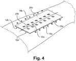
- FIGs. 1-4depict one embodiment of a wound closure device 10 and how the device 10 is used on a patient.
- the wound closure device 10includes a first magnet 12a and a second magnet 12b.
- the magnets 12a, 12bare flexible elongated strips capable of flexing along the longitudinal axis, such as shown in Fig. 3 .
- Each magnethas a top surface 24a, 24b, a bottom surface 14a, 14b, an outer edge 18a, 18b, and an inner edge 20a, 20b.
- the inner edges 20a, 20bhave opposite magnetic polarity. For example, if the inner edge 20a of the first magnet 12a is north, then the inner edge of 20b of the second magnet 12b is south, and vice versa.
- the removable sheet 26Attached to the magnets 12a, 12b is a removable sheet 26 having a top surface 27 and bottom surface 22.
- the removable sheet 26can be made of any flexible material, including polymers, polyvinyls, elastomers, thermoplastics, polyolefins, polyesters, or the like.
- the removable sheetindirectly connects the first magnet 12a to the second magnet 12b by adhering the top surfaces 24a, 24b of the first and second magnets 12a, 12b to the bottom surface 22 of the removable sheet 26.
- the bottom surface 22 of the removable sheet 20is removably affixed to the top surfaces 24a, 24b of the magnets 12a, 12b.
- the partition member 28may be made of the same material as the removable sheet 26 and may be integral with the sheet 26 or attached to the sheet 26.
- the elongated partition member 28runs substantially down the longitudinal axis of the removable sheet 20 and is designed to be positioned between and separate the two magnets 12a, 12b along their inner edges 20a, 20b. By having the partition member 28 between the inner edges 20a, 20b, the partition member 28 prevents the inner edge 20a of the first magnet 12a from directly contacting the inner edge 20b of the second magnet 12b.
- This configurationallows the practitioner to maneuver the device around the wound 13 when the magnets are not yet connected directly to each other so that the first magnet 12a can be positioned on one side of the wound 13 and the second magnet 12b can be positioned on the opposing side of wound 13, with the wound 13 positioned between the two magnets 12a, 12b.
- the elongated partition member 28may have a variety of structures and in on embodiment is an elongated tab having a width of less than 2 cm, a depth of less than 2 cm. The wider the partition member 28 is, then the larger the wound 13 that can be fit between the magnets 12a, 12b. However, if the partition member 28 is too wide, the magnets will be two far apart to attract each other once the partition member 28 is removed. If the partition member 28 is too thin, then the magnets 12a, 12b would be placed directly on top of the wound and not on adjacent skin.
- the depth of the partition member 28is substantially the same as the depth of each magnet 12a, 12b, so that the bottom of the partition member 28 is flush with the bottom surfaces of each magnet 12a, 12b when the removable sheet 26 and magnets 12a, 12b are connected together.
- the width and depth of the elongated partition member 28is less than 1 cm.
- the practitionerremoves the removable sheet 26, as shown in Fig. 3 , by peeling the removable sheet 20 off of the magnets 12a, 12b.
- the magnetsare still spaced apart from each other because the partition member 28 is still positioned between the magnets 12a, 12b.
- the inner edges 20a, 20b of the magnets 12a, 12bare drawn together, thereby reapproximating wound edges by pulling the skin underneath the magnets 12a, 12b together.
- the bottom surfaces of the magnets 14a, 14bmay have an adhesive layer.
- the adhesive layercan be covered with a peelable cover (not shown) designed to be removed before affixing the magnets 12a, 12b to the skin.
- the removable sheet 26may also have an adhesive layer, or the top surfaces of the magnets 24a, 24b may have an adhesive layer to affix the removable sheet 26 to the magnets 20a, 20b.
- the adhesive layeris a weak adhesive layer, which keeps the sheet 26 affixed to the magnets, but allows the sheet 26 to be easily peeled away from the magnets once the device 10 is placed on the patient.
- a practitionercould apply an adhesive directly on the patient's skin around a wound, and thereafter place the device on the skin adhesive.
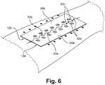
- the inner edge of the first magnet 12ais characterized has having a first plurality of notches 30a and the inner edge of the second magnet 12b is characterized as having a second plurality of notches 30b.
- the notches 30a, 30bcan be any size or shape, but are complementary shaped so that the protrusions 32a formed by the notches 30a on the first magnet 12a fit within the notches 30b of the second magnet 12b, and vice versa.
- the magnets 12a, 12bare spaced apart, as shown in Fig. 5 .
- the magnets 12a, 12battract each other so that the notches 30a, 30b interlock with the protrusions 32a, 32b on the opposing magnet, as shown in Fig. 6 .
- the notchesare V-shaped, but other shapes can be imagined without detracting from the spirit of the invention, such as square shaped, rectangular shaped, circular shaped, irregularly shaped, or any other shape where a complementary protrusion can fit within the notch of an opposing magnet.
- the notches 30a, 30bare advantageous because they prevent slippage and movement along the longitudinal axis of the inner edges due to the flanking effect of the arms of the notches and protrusions.
- Wound edge alignmentis a desirable feature of wound closure because if the wound's edges are not perfectly aligned, the resulting healed wound may have a "dog ear" deformity, which would require surgical correction.
- the anti-slippage feature created by the notches and protrusions along the inner edges of the magnetprevents the skin from sliding underneath the magnets.
- Protrusions and notchescan vary in size. In one embodiment, a protrusion tip is approximately 4 mm in height. In one embodiment, the length from protrusion tip to the adjacent protrusion tip is approximately 8 mm.
- the length of the magnetis approximately 8 cm. In one embodiment, the thickness of the magnet is approximately 1 mm and the width of each magnet, from the tip of a protrusion to the outer edge 18a, 18b, is approximately 2 cm. Differences in dimensions of notches and protrusions can be well tolerated such as notches and protrusions that are at least half or at least double the notch and protrusion disclosed above.
- each magnet 12a, 12b of device 10can be of any length, but preferable between 3 cm and 10 cm in length, and 2 cm and 6 cm in width.
- the height of each magnet 12a, 12bis between 0.5 mm and 5 mm, and approximately 1 mm in height.
- each magnet 12a, 12bis between 5 cm and 20 cm in length, between 1 cm and 6 cm in width, and between 0.5 mm and 10 mm in height. In another embodiment, the dimension of each magnet 12a, 12b is approximately 4 cm in length, 2 cm in width, and 1 mm in height.
- the magnetshave a protective covering or are enclosed within a housing, such as a polymer enclosure.
- a housingsuch as a polymer enclosure.
- Enclosures for magnets in wound healing deviceshave been disclosed in other wound healing devices, as well as additional layers within the enclosure to aid in healing, such as: insulation layers, absorbent layers, polymer layers, holes that allow for drainage of fluids, adhesive layers, and removable covers, which are described and illustrated in Fig. 1 and Fig. 2 of U.S. Patent No. 9,486,217 to Moustafa , which is fully incorporated herein by reference in its entirety.
- the enclosuremay be made of any one of number of polymers, but in a preferred embodiment is a silicone enclosure.
- Other materials for an enclosuremay be made from natural or synthetic polymers including rubber, neoprene, polyvinyl chloride, polyvinyl butyral, polystyrene, polyethylene, polypropylene, nylon, polyacrylonitrile.
- the magnets 12a, 12bmay be made from a number of materials, such as ferromagnetic materials, or rare-earth elements, such as magnets made from alloys of neodymium, iron and boron.
- ferromagnetic materialssuch as ferromagnetic materials
- rare-earth elementssuch as magnets made from alloys of neodymium, iron and boron.
- the advantage of rare-earth magnets, such as neodymium magnetsis that their crystalline structures have very high magnetic anisotropy and can retain high magnetic moments in the solid state.
- the magnetis a flexible magnet that is rolled or extruded in a magnetic film, and then cut to size into a magnetic sheet or strip.
- the magnetcomprises NdFeB magnetic powder, chlorinated polyethylene (CPE), and an annexing agent such as soybean oil.
- the magnet in the deviceis comprised of approximately 90.5% NdFeB powder, 8.5% CPE, and 1% annexing agent.
- NdFeB powdermay be comprised of approximately 31.0-31.8% PrNd, approximately 64-66.5% Fe, approximately 1.00-1.03% B, approximately 1.5-1.8% Dy, approximately 0.5-0.8% Co, approximately 0-0.25% Nb, and approximately 0.0-0.2% Al. Deviations from the percentages above that also allow for a strong but flexible magnet are allowed and known by persons having ordinary skill in the art.
- the adhesive used in the embodimentsmay be made from any one of a number of adhesive compositions, including: reusable adhesives, pressure sensitive adhesives, contact adhesives, resins, epoxies, polyurethane, cyanoacrylate (CA), polymers, acrylic-based adhesives that cure under ultraviolet (UV) light, silicone based adhesives, and polyolefinic polymers.
- a removable cover that protects the adhesive from the environment before usemay be a peel-off tape. The practitioner removes the adhesive cover before placing the device 10 on the patient's skin.
- plasticizersare commonly known and used in the art, and may include phthalate ester plasticizers commonly used in medical devices such as: dicarboxylic/triboxylic ester-based plasticizers, including Bis (2-ethylhexyl) phthalate, Di-n-butyl phthalate, or Diisooctyl phthalate.
- the inventionis advantageous for emergency situations when medical personnel are overloaded, or even in non-emergency situations for use with young children who would be more apprehensive regarding traditional wound closure devices and methods.
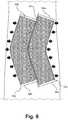
- Fig. 7 and Fig. 8illustrate another embodiment of the invention, where the magnets 12a, 12b placed on opposite edges of a wound 13 are not magnetic strips but instead or are comprised of magnetic powdered material 34a, 34b within a flexible enclosure 36a, 36b.
- the flexible enclosures 36a, 36bcan be made of any thin, flexible material, such as plastic, polyethylene, latex, nitrile, or the like, and allow the magnets 12a, 12b to be easily positioned on a patient to match the shape of the wound.
- the powder 34a, 34ballows the magnets 12a, 12b to maintain either a linear shape or non-linear shape after placement on a patient.
- the magnets 12a, 12bare in a non-linear shape.
- Other types of flexible enclosures for magnetic powdermay be envisioned without detracting from the spirit of the invention.
- the flexible enclosures 36a, 36bare hollow cylindrical tubular structures, but the shapes and sizes of the flexible enclosures 36a, 36b may vary without departing from the spirit of the invention.
- Examples of magnetic powder 34a, 34a that can fill the enclosures 36a, 36bcan be, but are not limited to: iron oxide, barium ferrite, strontium ferrite, magnetite, Iron (II,III) oxide, neodymium powder, rare earth magnet powder, or any other permanent magnet that can be powderized and placed within the flexible enclosures 36a, 36b.
- Fig. 7depicts the magnets 12a, 12b around the edges a non-linear wound before the magnets have attracted each other to reapproximate wound edges. Since the magnets 12a, 12b are comprised of magnetic powder 34a, 34b, the magnets 12a, 12b can be easily bent or curved and maintain their shapes.
- Fig. 7depicts the magnets 12a, 12b around the edges a non-linear wound before the magnets have attracted each other to reapproximate wound edges. Since the magnets 12a, 12b are comprised of magnetic powder 34a, 34b, the magnets 12a, 12b can be easily bent
- FIG. 8depicts the magnets 12a, 12b of Fig. 7 after the inner edges 38a, 38b of the magnets 12a, 12b have attracted to each other, thereby reapproximating wound edges.
- the inner edges 38a, 38b of the magnets 12a, 12b in Fig. 7 and 8are shown as non-linear inner edges 38a, 38, but can also be shaped to be straight linear inner edges to approximate linear wounds as well.
- the magnets illustrated in Figs. 7 and 8may have the same additional layers of adhesives, covers, and flexible sheets as described in the previous embodiments.
Landscapes
- Health & Medical Sciences (AREA)
- Life Sciences & Earth Sciences (AREA)
- Surgery (AREA)
- Heart & Thoracic Surgery (AREA)
- Engineering & Computer Science (AREA)
- Biomedical Technology (AREA)
- Nuclear Medicine, Radiotherapy & Molecular Imaging (AREA)
- Medical Informatics (AREA)
- Molecular Biology (AREA)
- Animal Behavior & Ethology (AREA)
- General Health & Medical Sciences (AREA)
- Public Health (AREA)
- Veterinary Medicine (AREA)
- Magnetic Treatment Devices (AREA)
Abstract
Description
- The present invention relates generally to a device useful for wound healing, and more particularly to a magnetic device that draws wound edges in proximity to each other.
- Wounds usually occur when there is trauma to the skin and underlying tissue. Types of trauma include lacerations, abrasions, incisions, punctures, and penetrations. After trauma, the wound begins to heal in a complex series of biochemical processes occurring in several wound-healing phases. The phases of healing are often categorized into a hemostasis phase, an inflammatory phase, a proliferative phase and a remodeling phase. In hemostasis, active bleeding is controlled by clotting. In the inflammatory phase, pathogens are removed by the body away from the wounded area, and biological factors are released (which later cause the division of cells involved in the proliferative phase). In the proliferative phase, new blood vessels are formed and wound contraction occurs. Also in the proliferative phase, epithelial cells cover the wound, providing an area of growth for new tissue. During contraction, the wound is made smaller by myofibroblasts attaching to the wound edges, and finally, during the remodeling phase, collagen fibers are realigned along tension lines formed during the earlier phases of healing.
- Not only is the process of wound healing complex, it is also fragile because many factors can lead to a disruption of proper wound healing, including re-injury of the tissue, bacterial infection, and physical stress on the damaged tissue. A variety of devices and methods have been used to aid in the wound healing process. These devices and methods are generally divided into one of three types: primary intention, secondary intention, and tertiary intention. The primary intention devices and methods bring the edges of the wounds together, so that the edges are reapproximated. Reapproximation helps to minimize scarring, and increases the speed at which wound contraction and healing occur. Examples of primary intention devices and methods include the use sutures, staples, tape, glue, and hooks. Primary intention techniques to heal wounds are the most common techniques used by practitioners.
- While not as commonly used, secondary intention devices and methods include first allowing the wound to first granulate without closing the wound. The wound is packed and drained, often daily, to remove debris and encourage granulation tissue formation. Still less common are tertiary intension devices and methods, which delay the closure of the wound even longer, so that the practitioner can close the wound at a later time. Tissue grafting is an example of a tertiary method for wound healing.
- Wound edge reapproximation is key to wound healing. If the edges of the wound are not immediately reapproximated soon after injury, healing may be delayed. This delay in healing may leads to scarring and infection. While in some circumstances a delay is advantageous, practitioners generally want to close an open wound as soon as possible.
- The traditional method to reapproximate wound edges is by sutures, where a practitioner stitches a threading material to connect opposing sides of a wound. Sutures and suturing techniques are well known in the prior art, such as described by
Fällman in U.S. Patent No. 8,267,959 . Other devices and methods to reapproximate wound edges include hooking devices, such as the hook closure device disclosed byBargon in U.S. Patent Application No. 13/266,825 , where a band placed over a wound has a multiplicity of hook elements that engage a mesh on the opposing side of a wound. - The use of adhesive strips is another method to aid in wound closure. In
U.S. Patent No. 4,825,866 to Pierce , adhesive strips are placed on opposite sides of a wound and drawn together to reapproximate the wound edges. Stapling and clipping the edges of wound are other techniques to reapproximate wound edges, as described byZadno in U.S. Patent No. 7,556,632 . - The use of magnets to reapproximate wound edges also has been previously described.
U.S. Patent Application No. 10/512,964 to Wheatley andU.S. Patent No. 9,402,605 to Viola 9,486,217 to Moustafa - Other compositions and methods to reapproximate wound edges include the use of medical adhesives, such as cyanoacrylate glues that provide for very tight, high-strength closure of wounds without the need for the physical closure accomplished with sutures. However, cyanoacrylate based glues have been associated with the formation of toxic byproducts, and even non-toxic versions are generally only useful for smaller, shallow lacerations in low-tension areas. These adhesives can be very unforgiving if the practitioner needs to remove the glue. Another disadvantage of using glues for wound closure is that leakage of glues can cause serious ramifications, especially if the adhesives are toxic and the wounds are near sensitive anatomical structures, such as the eye. Still another disadvantage is that adhesives can trap pathogens and other particles within the wound.
- Each type of wound closure device and technique has advantages and disadvantages. Sutures pose the risk of injury to the patient caused by the needle as well as to health care professions. The process of suturing also can take a substantial amount of time depending on the size of the wound. Using staples for wound closure is more rapid than suturing, however, unlike sutures, which may be absorbed by the body, staples usually have to be removed by a special tool. Sutures and staples also require applying local anesthesia, which could be dangerous to the patient, especially in the event of an allergic reaction. Furthermore, if the practitioner needs to enter the wound area, the sutures or staples need to be cut or removed, and both sutures and staples can lead to scarring.
- Complex wound closure devices that reduce some of these disadvantages have many individual parts, are difficult to apply, or are expensive. Accordingly, it would be advantageous to make available a novel wound closure device that reduces these stated disadvantages and there remains a need for quick and easy to use devices and methods to reapproximate wound edges.
- The present invention relates to a wound closure device and methods of reapproximating wound edges, which lead to improved wound healing. It is an object of the present invention to provide a magnetic wound closure device, such that when two magnets are attached to skin on opposites sides of a wound, the magnets attract each other, thereby pulling together the edges of the wound. Before the magnets reapproximate the wound edges, the magnets are separated by a partition on a peelable removable sheet so that the practitioner can place the device on the patient in a precise location before the magnets are drawn together. Once the removable sheet is removed from the magnet, the magnets draw in toward each other and pull in the skin edges around the wound. There are several advantages to the described invention, including: 1) placement of the device on a patient is faster than using staples or sutures, 2) no need to wait for an anesthetic, 3) less trauma, 4) no painful injections are needed, 5) inspection of the wound is simple because the device is easily removable, and 6) the device can be easily manufactured in a variety of sizes and shapes that accommodate various wound sizes.
- The magnetic wound closure device has a first magnet and a second magnet. The first magnet and second magnet are characterized as elongated magnets each having a top surface, a bottom surface, an inner edge, and an outer edge. The inner edge of the first magnet and the inner edge of the second magnet are opposite polarities of each other. The device also includes a removable sheet having an elongated partition member. The removable sheet is designed to indirectly connect the first magnet to the second magnet by adhering to the top surface of the first magnet and top surface of the second magnet. The removable sheet has a top surface and a bottom surface. The bottom surface of the removable sheet is removably affixed to the top surfaces of the two magnets. The elongated partition member extends from the bottom surface of the removable sheet and is designed to be positioned between the inner edges of the two magnets to separate them. The elongated partition member thereby prevents the inner edge of the magnets from directly contacting each other when the wound closure device is being placed along the edges of a wound. When the removable sheet and elongated partition member are removed from the magnets, the magnets are magnetically drawn to each other, causing the inner edges of each magnet to move together, thereby reapproximating wound edges.
- Another embodiment of the invention is where the bottom surfaces of the magnets have an adhesive layer to affix the magnets to the skin of a patient. The adhesive layer may be covered be an adhesive covering before being removed and placed on a patient. The removable sheet may be peelable and also have an adhesive layer on its bottom surface for affixing the removable sheet to the first and second magnet.
- Another embodiment of the invention is where the magnets include a protective covering, such as a polymer enclosure.
- In a further embodiment of the invention, the bottom surface of the removable sheet is sized and shaped substantially the same as the top surfaces of the magnets when the magnets are aligned together along their respective inner surfaces. The elongated partition member is positioned substantially along the middle of the longitudinal axis of the removable sheet.
- In another embodiment of the invention, the wound closure device includes a first magnet and a second magnet. The magnets are elongated magnets, each having a top surface, a bottom surface, and inner edge and an outer edge. The inner edge of the first magnet has an opposite polarity to the inner edge of the second magnet. To prevent the inner edges of the magnets from shifting along the longitudinal axis, each inner edge has a plurality of notches and protrusions. The notches on each inner edge are complementary shaped to protrusions on the opposing magnet, so that when the inner edges of each magnet are aligned with each other, the complementary notches and protrusions reduce the possibility of movement of the magnets along their respective inner edges. When the magnets are in proximity to each other, the inner edges move toward each other, thereby drawing the skin under the magnets to each other and reapproximating wound edges.
- In another embodiment, the plurality of notches and protrusions are serrations, and the serrations can be V-shaped serrations.
- In still another embodiment, the wound closure device having notched inner edges may be combined with the removable sheet having an elongated partition member to aid in placement of the device on the patient.
- Another object of the invention to provide a method of reapproximating wound edges. The steps involve: adhering the first magnet and the second magnet substantially near edges of a wound of a patient, and removing the removable sheet that has the elongated partition member separating the first and second magnet. The inner edge of the first wound closure device and the inner edge of the second wound closure device attract each and reapproximate wound edges.
- In another embodiment of the invention, the magnetic wound closure device is made of a first magnet and a second magnet. The first magnet has a first flexible enclosure and the second magnet has a second flexible enclosure. Each enclosure is filled with a powdered magnetic material. The magnetic powder within the enclosures allow the magnets to maintain either a linear or non-linear shape even after they are placed on the patient. The place of the first and the second magnet on opposing edges of a non-linear wound allow the magnets to attract each other along a non-linear inner edge of the first magnet and a non-linear edge of the second magnet, thereby reapproximating wound edges of a non-linear wound.
- These and other features and advantages of the present invention will become appreciated, as the same becomes better understood with reference to the specification, claims and drawings herein:
FIG. 1 is a bottom perspective view of an embodiment of a wound closure device.FIG. 2 is a top perspective exemplary view of the embodiment ofFig. 1 placed on an arm.FIG. 3 a top perspective exemplary view of the embodiment ofFig. 1 as the removable layer is being peeled off and magnets still separated.FIG. 4 is a top perspective exemplary view of the embodiment ofFig. 1 after the removable layer has been completely removed and the inner edges of the magnets have reapproximated the wound edges.FIG. 5 is a perspective view of a wound closure device having notched and protruding inner edges along two separated magnets.FIG. 6 is a perspective view of the wound closure device ofFig. 5 where the inner edges along the two magnets have been magnetically attracted to each other and connected.FIG. 7 is a top exemplary view of an embodiment where the wound closure device is made of two flexible tubes of powdered magnet material to easily curve around non-linear wound edges before the magnets attract together.FIG. 8 is a top exemplary view ofFIG. 7 after the magnets have attracted together to close the wound.- The invention now will be described more fully hereinafter with reference to the accompanying drawings, in which embodiments of the invention are shown. This invention may, however, be embodied in many different forms and should not be construed as limited to the embodiments set forth herein. Rather, these embodiments are provided so that this disclosure will be thorough and complete, and will fully convey the scope of the invention to those skilled in the art.
- It will be understood that when an element is referred to as being "on" another element, it can be directly on the other element or intervening elements may be present there between. As used herein, the term "and/or" includes any and all combinations of one or more of the associated listed items.
- It will be understood that, although the terms first, second, third etc. may be used herein to describe various elements, components, regions, layers and/or sections, these elements, components, regions, layers and/or sections should not be limited by these terms. These terms are only used to distinguish one element, component, region, layer or section from another element, component, region, layer or section.
- As used herein, the singular forms "a," "an," and "the," are intended to include the plural forms as well, unless the context clearly indicates otherwise. It will be further understood that the terms "comprises" and/or "comprising," "includes" and/or "including," and "have" and/or "having," when used in this specification, specify the presence of stated features, regions, integers, steps, operations, elements, and/or components, but do not preclude the presence or addition of one or more other features, regions, integers, steps, operations, elements, components, and/or groups thereof.
- Furthermore, relative terms, such as "lower" or "bottom," and "upper" or "top," and "inner" or "outer," may be used herein to describe one element's relationship to another element as illustrated in the Figures. It will be understood that relative terms are intended to encompass different orientations of the device in addition to the orientation depicted in the Figures.
- Unless otherwise defined, all terms used herein have the same meaning as commonly understood by one of ordinary skill in the art to which this invention belongs. It will be further understood that terms, such as those defined in commonly used dictionaries, should be interpreted as having a meaning that is consistent with their meaning in the context of the relevant art and the present disclosure, and will not be interpreted in an idealized or overly formal sense unless expressly so defined herein.
- Exemplary embodiments of the present invention are described herein with reference to idealized embodiments of the present invention. As such, variations from the shapes of the illustrations as a result, for example, of manufacturing techniques and/or tolerances, are to be expected. Thus, embodiments of the present invention should not be construed as limited to the particular shapes of regions illustrated herein but are to include deviations in shapes that result, for example, from manufacturing.
- A wound closure device is provided for closing wounds without sutures.
FIGs. 1-4 depict one embodiment of awound closure device 10 and how thedevice 10 is used on a patient. Thewound closure device 10 includes afirst magnet 12a and asecond magnet 12b. Themagnets Fig. 3 . Each magnet has atop surface bottom surface outer edge inner edge inner edges inner edge 20a of thefirst magnet 12a is north, then the inner edge of20b of thesecond magnet 12b is south, and vice versa. - Attached to the
magnets removable sheet 26 having atop surface 27 andbottom surface 22. Theremovable sheet 26 can be made of any flexible material, including polymers, polyvinyls, elastomers, thermoplastics, polyolefins, polyesters, or the like. The removable sheet indirectly connects thefirst magnet 12a to thesecond magnet 12b by adhering thetop surfaces second magnets bottom surface 22 of theremovable sheet 26. Thebottom surface 22 of the removable sheet20 is removably affixed to thetop surfaces magnets - Extending from the
bottom surface 22 of theremovable sheet 26 is anelongated partition member 28. Thepartition member 28 may be made of the same material as theremovable sheet 26 and may be integral with thesheet 26 or attached to thesheet 26. Theelongated partition member 28 runs substantially down the longitudinal axis of the removable sheet20 and is designed to be positioned between and separate the twomagnets inner edges partition member 28 between theinner edges partition member 28 prevents theinner edge 20a of thefirst magnet 12a from directly contacting theinner edge 20b of thesecond magnet 12b. This configuration allows the practitioner to maneuver the device around thewound 13 when the magnets are not yet connected directly to each other so that thefirst magnet 12a can be positioned on one side of thewound 13 and thesecond magnet 12b can be positioned on the opposing side ofwound 13, with thewound 13 positioned between the twomagnets - The
elongated partition member 28 may have a variety of structures and in on embodiment is an elongated tab having a width of less than 2 cm, a depth of less than 2 cm. The wider thepartition member 28 is, then the larger thewound 13 that can be fit between themagnets partition member 28 is too wide, the magnets will be two far apart to attract each other once thepartition member 28 is removed. If thepartition member 28 is too thin, then themagnets partition member 28 is substantially the same as the depth of eachmagnet partition member 28 is flush with the bottom surfaces of eachmagnet removable sheet 26 andmagnets elongated partition member 28 is less than 1 cm. - Once the
device 10 is placed over thewound 13, as shown inFig. 2 , the practitioner removes theremovable sheet 26, as shown inFig. 3 , by peeling the removable sheet20 off of themagnets Fig. 3 , the magnets are still spaced apart from each other because thepartition member 28 is still positioned between themagnets partition member 28 are peeled away from themagnets inner edges magnets magnets - To aid in adhering the magnets to the skin, the bottom surfaces of the
magnets magnets removable sheet 26 may also have an adhesive layer, or the top surfaces of themagnets removable sheet 26 to themagnets sheet 26 affixed to the magnets, but allows thesheet 26 to be easily peeled away from the magnets once thedevice 10 is placed on the patient. In an alternative manner to apply the device to the patient's skin, instead of an adhesive layer on the magnet, a practitioner could apply an adhesive directly on the patient's skin around a wound, and thereafter place the device on the skin adhesive. - Turning to
Fig. 5 andFig. 6 , in another embodiment of thedevice 10, the inner edge of thefirst magnet 12a is characterized has having a first plurality ofnotches 30a and the inner edge of thesecond magnet 12b is characterized as having a second plurality ofnotches 30b. Thenotches protrusions 32a formed by thenotches 30a on thefirst magnet 12a fit within thenotches 30b of thesecond magnet 12b, and vice versa. When thedevice 10 is placed on opposite sides of thewound 13, themagnets Fig. 5 . After placement on opposite sides of a wound, themagnets notches protrusions Fig. 6 . As shown inFig. 5 andFig. 6 , the notches are V-shaped, but other shapes can be imagined without detracting from the spirit of the invention, such as square shaped, rectangular shaped, circular shaped, irregularly shaped, or any other shape where a complementary protrusion can fit within the notch of an opposing magnet. - The
notches outer edge - The dimensions of each
magnet device 10 can be of any length, but preferable between 3 cm and 10 cm in length, and 2 cm and 6 cm in width. Preferably, the height of eachmagnet - In another embodiment, each
magnet magnet - Preferably, the magnets have a protective covering or are enclosed within a housing, such as a polymer enclosure. Enclosures for magnets in wound healing devices have been disclosed in other wound healing devices, as well as additional layers within the enclosure to aid in healing, such as: insulation layers, absorbent layers, polymer layers, holes that allow for drainage of fluids, adhesive layers, and removable covers, which are described and illustrated in
Fig. 1 andFig. 2 ofU.S. Patent No. 9,486,217 to Moustafa - The enclosure may be made of any one of number of polymers, but in a preferred embodiment is a silicone enclosure. Other materials for an enclosure may be made from natural or synthetic polymers including rubber, neoprene, polyvinyl chloride, polyvinyl butyral, polystyrene, polyethylene, polypropylene, nylon, polyacrylonitrile.
- The
magnets - In a preferred embodiment, the magnet is a flexible magnet that is rolled or extruded in a magnetic film, and then cut to size into a magnetic sheet or strip. In one magnet useful for wound closure, the magnet comprises NdFeB magnetic powder, chlorinated polyethylene (CPE), and an annexing agent such as soybean oil.
- In another embodiment, the magnet in the device is comprised of approximately 90.5% NdFeB powder, 8.5% CPE, and 1% annexing agent. In yet another embodiment, NdFeB powder may be comprised of approximately 31.0-31.8% PrNd, approximately 64-66.5% Fe, approximately 1.00-1.03% B, approximately 1.5-1.8% Dy, approximately 0.5-0.8% Co, approximately 0-0.25% Nb, and approximately 0.0-0.2% Al. Deviations from the percentages above that also allow for a strong but flexible magnet are allowed and known by persons having ordinary skill in the art.
- The adhesive used in the embodiments may be made from any one of a number of adhesive compositions, including: reusable adhesives, pressure sensitive adhesives, contact adhesives, resins, epoxies, polyurethane, cyanoacrylate (CA), polymers, acrylic-based adhesives that cure under ultraviolet (UV) light, silicone based adhesives, and polyolefinic polymers. A removable cover that protects the adhesive from the environment before use may be a peel-off tape. The practitioner removes the adhesive cover before placing the
device 10 on the patient's skin. - The inclusion of plasticizers within the polymer composition of the enclosure lowers the glass transition temperature (Tg) of the polymer, therefore allowing
device 10 to flex when themagnets - Since no sutures or staples are used when applying the
device 10, the invention is advantageous for emergency situations when medical personnel are overloaded, or even in non-emergency situations for use with young children who would be more apprehensive regarding traditional wound closure devices and methods. Fig. 7 andFig. 8 illustrate another embodiment of the invention, where themagnets wound 13 are not magnetic strips but instead or are comprised of magneticpowdered material flexible enclosure flexible enclosures magnets powder magnets Fig. 7 andFig. 8 , themagnets flexible enclosures flexible enclosures - Examples of
magnetic powder enclosures flexible enclosures Fig. 7 depicts themagnets magnets magnetic powder magnets Fig. 8 depicts themagnets Fig. 7 after theinner edges magnets inner edges magnets Fig. 7 and8 are shown as non-linearinner edges 38a, 38, but can also be shaped to be straight linear inner edges to approximate linear wounds as well. - The magnets illustrated in
Figs. 7 and8 may have the same additional layers of adhesives, covers, and flexible sheets as described in the previous embodiments. - The preceding embodiments may be considered based on the following feature analysis:
- A 1st magnetic
wound closure device 10 comprising:- a
first magnet 12a and asecond magnet 12b, thefirst magnet 12a characterized as having a firstflexible enclosure second magnet 12b having a secondflexible enclosure - wherein the first and the second enclosures each enclose a powdered magnetic material, the powdered magnetic material permits the
first magnet 12a and thesecond magnet 12b to maintain a linear or non-linear shape; and, - wherein the first enclosure and the second enclosures are each elongated hollow tubular members;
- whereby placement of the
first magnet 12a and thesecond magnet 12b on opposing edges of anon-linear wound 13 allow the first and the second magnets to attract each other along a non-linearinner edge first magnet 12a and a non-linearinner edge second magnet 12b, thereby reapproximating wound 13 edges of anon-linear wound 13.
- a
- A 2nd magnetic
wound closure device 10 according to the 1st magneticwound closure device 10, wherein the powdered magnetic material is an iron oxide and the firstflexible enclosure flexible enclosure - A 3rd magnetic
wound closure device 10 according to the 1st magneticwound closure device 10, wherein the length of the first enclosure and the second enclosure is between 3 cm and 10 cm, and the width of the first enclosure and the second enclosure is between 2 cm and 6 cm. - A 4th magnetic
wound closure device 10 according to the 1st magneticwound closure device 10, wherein the lengths of the first enclosure and the second enclosure are each between 5 cm and 20 cm, and the widths of the first enclosure and the second enclosure are each between 1 cm and 6 cm. - A 5th magnetic
wound closure device 10 according to the 2nd magneticwound closure device 10, wherein the length of the first enclosure and the second enclosure is between 3 cm and 10 cm, and the width of the first enclosure and the second enclosure is between 2 cm and 6 cm. - A 6th magnetic
wound closure device 10 according to the 2nd magneticwound closure device 10, wherein the lengths of the first enclosure and the second enclosure are each between 5 cm and 20 cm, and the widths of the first enclosure and the second enclosure are each between 1 cm and 6 cm. - A 7th magnetic
wound closure device 10 comprising:- a
first magnet 12a and asecond magnet 12b, thefirst magnet 12a characterized as having a firstflexible enclosure second magnet 12b having a secondflexible enclosure - wherein the first and the second enclosures each enclose a powdered magnetic material, the powdered magnetic material permits the
first magnet 12a and thesecond magnet 12b to maintain a linear or non-linear shape; and, - wherein the first enclosure and the second enclosures are each elongated hollow tubular members;
- wherein the powdered magnetic material is an iron oxide and the first
flexible enclosure flexible enclosure - wherein the length of the first enclosure and the second enclosure is between 3 cm and 10 cm, and the width of the first enclosure and the second enclosure is between 2 cm and 6 cm;
- whereby placement of the
first magnet 12a and thesecond magnet 12b on opposing edges of anon-linear wound 13 allow the first and the second magnets to attract each other along a non-linearinner edge first magnet 12a and a non-linearinner edge second magnet 12b, thereby reapproximating wound 13 edges of anon-linear wound 13.
- a
Claims (15)
- A magnetic wound closure device (10) comprising:i) a first magnet (12a) and a second magnet (12b), the first magnet (12a) and the second magnet (12b) characterized as elongated magnets each having a top surface (24a, 24b, 27), a bottom surface (14a, 14b, 22), an inner edge (20a, 20b), and an outer edge (18a, 18b), wherein the inner edge (20a, 20b) of the first magnet (12a) has an opposite polarity to the inner edge (20a, 20b) of the second magnet (12b);ii) a removable sheet (26, 20) having an elongated partition member (28), the removable sheet (26, 20) designed to position the first magnet (12a) relative to the second magnet (12b) by adhering to the top surface (24a, 24b, 27) of the first magnet (12a) and the top surface (24a, 24b, 27) of the second magnet (12b),wherein the removable sheet (26, 20) is characterized as having a top surface (24a, 24b, 27) and a bottom surface (14a, 14b, 22), wherein the bottom surface (14a, 14b, 22) of the removable sheet (26, 20) is removably affixed to the top surface (24a, 24b, 27) of the first magnet (12a) and the top surface (24a, 24b, 27) of the second magnet (12b);
wherein the elongated partition member (28) extends from the bottom surface (14a, 14b, 22) of the removable sheet (26, 20) and is designed to be positioned between, and separate, the inner edge (20a, 20b) of the first magnet (12a) and the inner edge (20a, 20b) of the second magnet (12b), thereby preventing the inner edge (20a, 20b) of the first magnet (12a) from directly contacting the inner edge (20a, 20b) of the second magnet (12b) when the magnetic wound closure device (10) is being placed along edges of a wound (13); and,
wherein the elongated partition member (28) is an elongated tab having a width of less than 2 cm, a depth of less than 2 cm, and wherein the first magnet (12a) and the second magnet (12b) have a depth of less than 2 cm;
whereby the distance between the inner surface of the first magnet (12a) and the inner surface of the second magnet (12b) is less than 2 cm when the elongated tab is positioned between the inner surface of the first magnet (12a) and the inner surface of the second magnet (12b); and
whereby when the removable sheet (26, 20) and the elongated partition member (28) are removed from the first and the second magnets, the first and second magnets are magnetically drawn to each other, causing the inner edge (20a, 20b) of the first magnet (12a) to move toward the inner edge (20a, 20b) of the second magnet (12b), thereby reapproximating wound (13) edges by pulling skin underneath the first magnet (12a) and the second magnet (12b) together. - The magnetic wound closure device (10) of claim 1, wherein the bottom surfaces of the first magnet (12a) and the second magnet (12b) each have an adhesive layer for affixing the first magnet (12a) and the second magnet (12b) to skin of a patient; and,
wherein the adhesive layer is protected by a removable adhesive layer cover designed to be removed before affixing the first magnet (12a) and the second magnet (12b) to skin of a patient. - The magnetic wound closure device 10 of claim 1 or 2, wherein the removable sheet (26, 20) is a peelable sheet having an adhesive layer on the bottom surface (14a, 14b, 22) of the removable sheet (26, 20) for affixing the removable sheet (26, 20) to the first magnet (12a) and the second magnet (12b).
- The magnetic wound closure device (10) of one of the preceding claims, wherein the first magnet (12a) and the second magnet (12b) are flexible magnets capable of flexing in a longitudinal direction; and,
wherein the removable sheet (26, 20) is capable of flexing in a longitudinal direction. - The magnetic wound closure device of one of the preceding claims, wherein the first magnet (12a) and the second magnet (12b) are each enclosed within a protective covering.
- The magnetic wound closure device of claim 5, wherein the protective covering is a polymer enclosure.
- The magnetic wound closure device of one of the preceding claims, wherein the elongated tab having a width of less than 1 cm, a depth of less than 1 cm, and wherein the first magnet (12a) and the second magnet (12b) each have a depth of less than 1 cm.
- The magnetic wound closure device of one of the preceding claims, wherein the bottom surface (14a, 14b, 22) of the removable sheet (26, 20) is sized and shaped substantially the same as the top surfaces of the first and second magnets when the first and second magnets are oriented together along their respective inner surfaces; and,
wherein the elongated partition member (28) is positioned substantially along the middle of the longitudinal axis of the removable sheet (26, 20). - The magnetic wound closure device of one of the preceding claims, wherein the first and second magnets are characterized as neodymium magnets.
- The magnetic wound closure device of one of the preceding claims, wherein each of the first and second magnets have dimensions in the range of between 5 cm and 20 cm in length and 1 cm and 6 cm in width.
- A magnetic wound closure device comprising:a first magnet (12a) and a second magnet (12b), the first magnet (12a) and the second magnet (12b) are characterized as elongated magnets each having a top surface (24a, 24b, 27), a bottom surface (14a, 14b, 22), an inner edge (20a, 20b), and an outer edge (18a, 18b);a removable sheet (26, 20) having an elongated partition member (28), the removable sheet (26, 20) designed to position the first magnet (12a) relative to the second magnet (12b) by adhering to the top surface (24a, 24b, 27) of the first magnet (12a) and the top surface (24a, 24b, 27) of the second magnet (12b),wherein the removable sheet (26, 20) is characterized as having a top surface (24a, 24b, 27) and a bottom surface (14a, 14b, 22), wherein the bottom surface (14a, 14b, 22) of the removable sheet (26, 20) is removably affixed to the top surface (24a, 24b, 27) of the first magnet (12a) and the top surface (24a, 24b, 27) of the second magnet (12b);wherein the elongated partition member (28) extends from the bottom surface (14a, 14b, 22) of the removable sheet (26, 20) and is designed to be positioned between, and separate, the inner edge (20a, 20b) of the first magnet (12a) and the inner edge (20a, 20b) of the second magnet (12b), thereby preventing the inner edge (20a, 20b) of the first magnet (12a) from directly contacting the inner edge (20a, 20b) of the second magnet (12b) when the magnetic wound closure device is being placed along edges of a wound (13); and,wherein the elongated partition member (28) is an elongated tab having a width of less than 2 cm, a depth of less than 2 cm, and wherein the first magnet (12a) and the second magnet (12b) have a depth of less than 2 cm;whereby the distance between the inner surface of the first magnet (12a) and the inner surface of the second magnet (12b) is less than 2 cm when the elongated tab is positioned between the inner surface of the first magnet (12a) and the inner surface of the second magnet (12b); and,wherein the inner edge (20a, 20b) of the first magnet (12a) has an opposite polarity to the inner edge (20a, 20b) of the second magnet (12b); and,wherein the inner edge (20a, 20b) of the first magnet (12a) is characterized as having a first plurality of notches (30a, 30b) and a first plurality of protrusions (32a, 32b), and the inner edge (20a, 20b) of the second magnet (12b) is characterized as having a second plurality of notches (30a, 30b) and a second plurality of protrusions (32a, 32b) and is complimentarily shaped to the inner edge (20a, 20b) of the first magnet (12a);whereby when the first plurality of notches (30a, 30b) of the first magnet (12a) are aligned with the second plurality of protrusions (32a, 32b) on the second magnet (12b), the first and the second magnets interlock with each other and prevent longitudinal slippage along the inner edges (38a, 38b, 38) of the first magnet (12a) and the second magnet (12b); andwhereby the first and the second magnets are magnetically drawn to each other, causing the inner edge (20a, 20b) of the first magnet (12a) to move toward the inner edge (20a, 20b) of the second magnet (12b), thereby reapproximating wound edges when the magnetic wound closure device is placed along wound edges of a patient.
- The magnetic wound closure device of claim 11, wherein the first plurality of notches (30a, 30b) and the first plurality of protrusions (32a, 32b) are characterized as serrations.
- The magnetic wound closure device of claim 11 or 12, wherein the first and second plurality of notches (30a, 30b) and first and second plurality of protrusions (32a, 32b) are V-shaped.
- The magnetic wound closure device (10) of one of claims 11 to 13, further comprising:the removable sheet (26, 20) designed to indirectly connect the first magnet (12a) to the second magnet (12b) by adhering to the top surface (24a, 24b, 27) of the first magnet (12a) and the top surface (24a, 24b, 27) of the second magnet (12b),wherein the removable sheet (26, 20) is characterized as having a top surface (24a, 24b, 27) and a bottom surface (14a, 14b), wherein the bottom surface (14a, 14b) of the removable sheet (26, 20) is removably affixed to the top surface (24a, 24b, 27) of the first magnet (12a) and the top surface (24a, 24b, 27) of the second magnet (12b); and,wherein the elongated partition member (28) extends from the bottom surface (14a, 14b) of the removable sheet (26, 20) and is designed to separate the inner edge (20a, 20b) of the first magnet (12a) from the inner edge (20a, 20b) of the second magnet (12b), thereby preventing the inner edge (20a, 20b) of the first magnet (12a) from directly contacting the inner edge (20a, 20b) of the second magnet (12b) when the magnetic wound closure device (10) is being placed along edges of a wound (13);whereby when the removable sheet (26, 20) and elongated partition member (28) are removed from the first and second magnets, the first and the second magnets are magnetically drawn to each other, causing the inner edge (20a, 20b) of the first magnet (12a) to move toward the inner edge (20a, 20b) of the second magnet (12b), thereby reapproximating wound edges.
- The magnetic wound closure device (10) of one of claims 11 to 14, further comprising:a removable sheet (26, 20) having an elongated partition member (28), the removable sheet (26, 20) designed to indirectly connect the first magnet (12a) to the second magnet (12b) by adhering to the top surface (24a, 24b, 27) of the first magnet (12a) and the top surface (24a, 24b, 27) of the second magnet (12b),wherein the removable sheet (26, 20) is characterized as having a top surface (24a, 24b, 27) and a bottom surface (14a, 14b), wherein the bottom surface (14a, 14b) of the removable sheet (26, 20) is removably affixed to the top surface (24a, 24b, 27) of the first magnet (12a) and the top surface (24a, 24b, 27) of the second magnet (12b); and,wherein the elongated partition member (28) extends from the bottom surface (14a, 14b) of the removable sheet (26, 20) and is designed to be positioned between, and separate, the inner edge (20a, 20b) of the first magnet (12a) and the inner edge (20a, 20b) of the second magnet (12b), thereby preventing the inner edge (20a, 20b) of the first magnet (12a) from directly contacting the inner edge (20a, 20b) of the second magnet (12b) when the magnetic wound closure device (10) is being placed along edges of a wound (13);whereby when the removable sheet (26, 20) and elongated partition member (28) are removed from the first and second magnets, the first and second magnets are magnetically drawn to each other, causing the inner edge (20a, 20b) of the first magnet (12a) to move toward the inner edge (20a, 20b) of the second magnet (12b), thereby reapproximating wound edges.
Applications Claiming Priority (3)
| Application Number | Priority Date | Filing Date | Title |
|---|---|---|---|
| US15/381,444US9693776B1 (en) | 2016-12-16 | 2016-12-16 | Magnetic wound closure device and method of use |
| US15/625,703US10729439B2 (en) | 2016-12-16 | 2017-06-16 | Magnetic wound closure device and method of use |
| EP17204427.3AEP3335643A1 (en) | 2016-12-16 | 2017-11-29 | Magnetic wound closure device |
Related Parent Applications (1)
| Application Number | Title | Priority Date | Filing Date |
|---|---|---|---|
| EP17204427.3ADivisionEP3335643A1 (en) | 2016-12-16 | 2017-11-29 | Magnetic wound closure device |
Publications (2)
| Publication Number | Publication Date |
|---|---|
| EP3485820A1true EP3485820A1 (en) | 2019-05-22 |
| EP3485820B1 EP3485820B1 (en) | 2020-12-30 |
Family
ID=60569643
Family Applications (2)
| Application Number | Title | Priority Date | Filing Date |
|---|---|---|---|
| EP17204427.3AWithdrawnEP3335643A1 (en) | 2016-12-16 | 2017-11-29 | Magnetic wound closure device |
| EP18213883.4AActiveEP3485820B1 (en) | 2016-12-16 | 2017-11-29 | Magnetic wound closure device |
Family Applications Before (1)
| Application Number | Title | Priority Date | Filing Date |
|---|---|---|---|
| EP17204427.3AWithdrawnEP3335643A1 (en) | 2016-12-16 | 2017-11-29 | Magnetic wound closure device |
Country Status (4)
| Country | Link |
|---|---|
| US (1) | US10729439B2 (en) |
| EP (2) | EP3335643A1 (en) |
| CN (1) | CN108201456B (en) |
| ES (1) | ES2863953T3 (en) |
Families Citing this family (6)
| Publication number | Priority date | Publication date | Assignee | Title |
|---|---|---|---|---|
| CN109394286A (en)* | 2018-12-07 | 2019-03-01 | 中国人民解放军陆军军医大学第附属医院 | Special-shaped surgical wound stitching devices based on 3D printing technique and preparation method thereof |
| CN113795641A (en)* | 2019-01-18 | 2021-12-14 | 宝山控股有限责任公司 | System and method for producing magnetic receptive and magnetic layers for surface covering systems |
| EP4044932A4 (en)* | 2019-10-15 | 2024-02-21 | The Regents of the University of California | SURGICAL CLOSURE DEVICE WITH BIOLOGICAL ZIPPER |
| CN111904599A (en)* | 2020-09-18 | 2020-11-10 | 象山县第一人民医院医疗健康集团 | Mechanical arm for thoracoscope |
| US11399833B2 (en)* | 2020-10-19 | 2022-08-02 | Covidien Lp | Anvil buttress attachment for surgical stapling apparatus |
| WO2022192862A1 (en)* | 2021-03-08 | 2022-09-15 | Ann & Robert H. Lurie Children's Hospital of Chicago | Method and system for medical device securement, wound closure, and wound/incision dressings |
Citations (5)
| Publication number | Priority date | Publication date | Assignee | Title |
|---|---|---|---|---|
| WO2006110420A2 (en)* | 2005-04-12 | 2006-10-19 | Wilk Patent, Llc | Device utilizing magnetic elements useful in medical treatment method |
| US20070060951A1 (en)* | 2005-09-15 | 2007-03-15 | Shannon Francis L | Atrial tissue fixation device |
| US20140214078A1 (en)* | 2013-01-28 | 2014-07-31 | Moustafa Moustafa | Magnetic Wound Closure Assembly and Method of Use |
| US20150088195A1 (en)* | 2013-09-23 | 2015-03-26 | Moustafa Moustafa | Magnetic Wound Closure Device and Method of Use |
| WO2016091833A1 (en)* | 2014-12-08 | 2016-06-16 | Continental Structures Bvba | Medical dressing for achieving an invisible or less visible scar and method of use |
Family Cites Families (21)
| Publication number | Priority date | Publication date | Assignee | Title |
|---|---|---|---|---|
| US3102314A (en) | 1959-10-01 | 1963-09-03 | Sterling W Alderfer | Fastener for adjacent surfaces |
| GB1068747A (en)* | 1964-12-09 | 1967-05-10 | Johnson & Johnson | Surgical dressings |
| DE2447681A1 (en)* | 1974-10-07 | 1976-04-15 | Magnet Service Gmbh | Permanent magnet closure for surgical incision - wounds are closed without stitching and directional tissue growth occurs |
| SU1447356A1 (en)* | 1987-05-11 | 1988-12-30 | Я. Г. Жуковский, В. С. Прокопчук и Г. Г. Фишер | Arrangement for closing colostoma |
| US4945049A (en)* | 1987-08-18 | 1990-07-31 | Research Development Corporation | Method for preparing magnetic powder |
| US4825866A (en) | 1987-08-27 | 1989-05-02 | Robert Pierce | Wound closure device |
| US5423736A (en) | 1992-04-02 | 1995-06-13 | New Dimensions In Medicine, Inc. | Wound dressing with dehydrated hydrogel gauze |
| US5478308A (en) | 1992-04-02 | 1995-12-26 | New Dimensions In Medicine, Inc. | Wound packing and package therefor |
| US5411730A (en)* | 1993-07-20 | 1995-05-02 | Research Corporation Technologies, Inc. | Magnetic microparticles |
| FR2760627A1 (en)* | 1997-03-14 | 1998-09-18 | Jean Pierre Pozzi | Suturing system for human tissue sections or similar |
| ITMI981150A1 (en)* | 1998-05-22 | 1999-11-22 | Sama S P A | MAGNETIC CLOSURE DEVICE FOR LEATHER GOODS AND SIMILAR CLOTHING |
| US6730014B2 (en) | 2001-01-05 | 2004-05-04 | Peter J. Wilk | Medical treatment method and device utilizing magnetic particles |
| EP1553877A4 (en) | 2002-05-06 | 2007-04-04 | Univ Drexel | TISSUE BONDING DEVICES CAPABLE OF DELIVERING BIOACTIVE AGENTS AND METHODS OF USE THEREOF |
| US8267959B2 (en) | 2003-12-19 | 2012-09-18 | Radi Medical Systems Ab | Technique for securing a suture |
| US7556632B2 (en) | 2004-07-09 | 2009-07-07 | Reza Zadno | Device and method for repairing tissue |
| US8157839B2 (en) | 2004-08-31 | 2012-04-17 | Wadsworth Medical Technologies, Inc. | Systems and methods for closing a tissue opening |
| US8680360B2 (en) | 2006-09-26 | 2014-03-25 | Smith & Nephew Inc. | Lattice dressing |
| DE102009020763A1 (en) | 2008-05-15 | 2009-11-19 | Aesculap Aktiengesellschaft | wound closure |
| US9402605B2 (en) | 2009-04-16 | 2016-08-02 | Covidien Lp | Magnetically retained incision closure devices and methods of incision closure using same |
| US20150272558A1 (en)* | 2014-03-25 | 2015-10-01 | Boston Scientific Scimed, Inc. | Devices, methods and kits for tissue approximation |
| CN203953717U (en)* | 2014-05-05 | 2014-11-26 | 兰州大学 | A kind of adjustable magnetic Skin stretching device |
- 2017
- 2017-06-16USUS15/625,703patent/US10729439B2/enactiveActive
- 2017-11-29EPEP17204427.3Apatent/EP3335643A1/ennot_activeWithdrawn
- 2017-11-29EPEP18213883.4Apatent/EP3485820B1/enactiveActive
- 2017-11-29ESES18213883Tpatent/ES2863953T3/enactiveActive
- 2017-12-04CNCN201711260881.0Apatent/CN108201456B/enactiveActive
Patent Citations (5)
| Publication number | Priority date | Publication date | Assignee | Title |
|---|---|---|---|---|
| WO2006110420A2 (en)* | 2005-04-12 | 2006-10-19 | Wilk Patent, Llc | Device utilizing magnetic elements useful in medical treatment method |
| US20070060951A1 (en)* | 2005-09-15 | 2007-03-15 | Shannon Francis L | Atrial tissue fixation device |
| US20140214078A1 (en)* | 2013-01-28 | 2014-07-31 | Moustafa Moustafa | Magnetic Wound Closure Assembly and Method of Use |
| US20150088195A1 (en)* | 2013-09-23 | 2015-03-26 | Moustafa Moustafa | Magnetic Wound Closure Device and Method of Use |
| WO2016091833A1 (en)* | 2014-12-08 | 2016-06-16 | Continental Structures Bvba | Medical dressing for achieving an invisible or less visible scar and method of use |
Also Published As
| Publication number | Publication date |
|---|---|
| US20180168653A1 (en) | 2018-06-21 |
| ES2863953T3 (en) | 2021-10-13 |
| EP3485820B1 (en) | 2020-12-30 |
| CN108201456A (en) | 2018-06-26 |
| CN108201456B (en) | 2019-06-28 |
| EP3335643A1 (en) | 2018-06-20 |
| US10729439B2 (en) | 2020-08-04 |
Similar Documents
| Publication | Publication Date | Title |
|---|---|---|
| EP3485820B1 (en) | Magnetic wound closure device | |
| US9486217B2 (en) | Magnetic wound closure device and method of use | |
| US9693776B1 (en) | Magnetic wound closure device and method of use | |
| US20140214078A1 (en) | Magnetic Wound Closure Assembly and Method of Use | |
| US8945062B2 (en) | Barrier system to reduce the rates of line-related infections | |
| US8105353B2 (en) | Wound closure kit and method of using the same | |
| EP3119360B1 (en) | Wound management system and methods of using | |
| US20130092178A1 (en) | Surgical wound closure device | |
| AU2019204693A1 (en) | Surgical incision and closure apparatus | |
| EP3574848A1 (en) | Surgical incision and closure apparatus | |
| NZ519239A (en) | Bandage for wound or incision closure | |
| WO2014116281A1 (en) | Atraumatic wound care and closure system | |
| AU2005279860A2 (en) | Systems and methods for closing a tissue opening | |
| EP4368158A2 (en) | Wound closure system | |
| EP2768450B1 (en) | Closure device for closing opened blood vessels | |
| JP2012152552A (en) | Catheter mounting device | |
| KR20220021197A (en) | Medical suturing device | |
| EP1675521B1 (en) | Surgical wound closure device | |
| EP3695819A1 (en) | Devices for wound closure | |
| KR200451650Y1 (en) | Surgical drape | |
| DE2447681A1 (en) | Permanent magnet closure for surgical incision - wounds are closed without stitching and directional tissue growth occurs | |
| KR102195143B1 (en) | Medical band | |
| US20240398626A1 (en) | Wound closure system, kits and method | |
| GB2290969A (en) | Wound Closure | |
| EP3866739A1 (en) | Protective dressing |
Legal Events
| Date | Code | Title | Description |
|---|---|---|---|
| PUAI | Public reference made under article 153(3) epc to a published international application that has entered the european phase | Free format text:ORIGINAL CODE: 0009012 | |
| STAA | Information on the status of an ep patent application or granted ep patent | Free format text:STATUS: THE APPLICATION HAS BEEN PUBLISHED | |
| AC | Divisional application: reference to earlier application | Ref document number:3335643 Country of ref document:EP Kind code of ref document:P | |
| AK | Designated contracting states | Kind code of ref document:A1 Designated state(s):AL AT BE BG CH CY CZ DE DK EE ES FI FR GB GR HR HU IE IS IT LI LT LU LV MC MK MT NL NO PL PT RO RS SE SI SK SM TR | |
| AX | Request for extension of the european patent | Extension state:BA ME | |
| STAA | Information on the status of an ep patent application or granted ep patent | Free format text:STATUS: REQUEST FOR EXAMINATION WAS MADE | |
| 17P | Request for examination filed | Effective date:20191120 | |
| RBV | Designated contracting states (corrected) | Designated state(s):AL AT BE BG CH CY CZ DE DK EE ES FI FR GB GR HR HU IE IS IT LI LT LU LV MC MK MT NL NO PL PT RO RS SE SI SK SM TR | |
| STAA | Information on the status of an ep patent application or granted ep patent | Free format text:STATUS: EXAMINATION IS IN PROGRESS | |
| 17Q | First examination report despatched | Effective date:20200131 | |
| GRAP | Despatch of communication of intention to grant a patent | Free format text:ORIGINAL CODE: EPIDOSNIGR1 | |
| STAA | Information on the status of an ep patent application or granted ep patent | Free format text:STATUS: GRANT OF PATENT IS INTENDED | |
| RIC1 | Information provided on ipc code assigned before grant | Ipc:A61B 17/08 20060101AFI20200512BHEP Ipc:A61B 17/00 20060101ALN20200512BHEP | |
| INTG | Intention to grant announced | Effective date:20200608 | |
| GRAS | Grant fee paid | Free format text:ORIGINAL CODE: EPIDOSNIGR3 | |
| GRAJ | Information related to disapproval of communication of intention to grant by the applicant or resumption of examination proceedings by the epo deleted | Free format text:ORIGINAL CODE: EPIDOSDIGR1 | |
| GRAL | Information related to payment of fee for publishing/printing deleted | Free format text:ORIGINAL CODE: EPIDOSDIGR3 | |
| STAA | Information on the status of an ep patent application or granted ep patent | Free format text:STATUS: EXAMINATION IS IN PROGRESS | |
| GRAR | Information related to intention to grant a patent recorded | Free format text:ORIGINAL CODE: EPIDOSNIGR71 | |
| STAA | Information on the status of an ep patent application or granted ep patent | Free format text:STATUS: GRANT OF PATENT IS INTENDED | |
| INTC | Intention to grant announced (deleted) | ||
| RIC1 | Information provided on ipc code assigned before grant | Ipc:A61B 17/00 20060101ALN20201014BHEP Ipc:A61B 17/08 20060101AFI20201014BHEP | |
| GRAA | (expected) grant | Free format text:ORIGINAL CODE: 0009210 | |
| STAA | Information on the status of an ep patent application or granted ep patent | Free format text:STATUS: THE PATENT HAS BEEN GRANTED | |
| INTG | Intention to grant announced | Effective date:20201028 | |
| AC | Divisional application: reference to earlier application | Ref document number:3335643 Country of ref document:EP Kind code of ref document:P | |
| AK | Designated contracting states | Kind code of ref document:B1 Designated state(s):AL AT BE BG CH CY CZ DE DK EE ES FI FR GB GR HR HU IE IS IT LI LT LU LV MC MK MT NL NO PL PT RO RS SE SI SK SM TR | |
| REG | Reference to a national code | Ref country code:GB Ref legal event code:FG4D | |
| REG | Reference to a national code | Ref country code:AT Ref legal event code:REF Ref document number:1349132 Country of ref document:AT Kind code of ref document:T Effective date:20210115 | |
| REG | Reference to a national code | Ref country code:DE Ref legal event code:R096 Ref document number:602017030743 Country of ref document:DE | |
| REG | Reference to a national code | Ref country code:IE Ref legal event code:FG4D | |
| PG25 | Lapsed in a contracting state [announced via postgrant information from national office to epo] | Ref country code:RS Free format text:LAPSE BECAUSE OF FAILURE TO SUBMIT A TRANSLATION OF THE DESCRIPTION OR TO PAY THE FEE WITHIN THE PRESCRIBED TIME-LIMIT Effective date:20201230 Ref country code:FI Free format text:LAPSE BECAUSE OF FAILURE TO SUBMIT A TRANSLATION OF THE DESCRIPTION OR TO PAY THE FEE WITHIN THE PRESCRIBED TIME-LIMIT Effective date:20201230 Ref country code:GR Free format text:LAPSE BECAUSE OF FAILURE TO SUBMIT A TRANSLATION OF THE DESCRIPTION OR TO PAY THE FEE WITHIN THE PRESCRIBED TIME-LIMIT Effective date:20210331 Ref country code:NO Free format text:LAPSE BECAUSE OF FAILURE TO SUBMIT A TRANSLATION OF THE DESCRIPTION OR TO PAY THE FEE WITHIN THE PRESCRIBED TIME-LIMIT Effective date:20210330 | |
| REG | Reference to a national code | Ref country code:AT Ref legal event code:MK05 Ref document number:1349132 Country of ref document:AT Kind code of ref document:T Effective date:20201230 | |
| PG25 | Lapsed in a contracting state [announced via postgrant information from national office to epo] | Ref country code:SE Free format text:LAPSE BECAUSE OF FAILURE TO SUBMIT A TRANSLATION OF THE DESCRIPTION OR TO PAY THE FEE WITHIN THE PRESCRIBED TIME-LIMIT Effective date:20201230 Ref country code:LV Free format text:LAPSE BECAUSE OF FAILURE TO SUBMIT A TRANSLATION OF THE DESCRIPTION OR TO PAY THE FEE WITHIN THE PRESCRIBED TIME-LIMIT Effective date:20201230 Ref country code:BG Free format text:LAPSE BECAUSE OF FAILURE TO SUBMIT A TRANSLATION OF THE DESCRIPTION OR TO PAY THE FEE WITHIN THE PRESCRIBED TIME-LIMIT Effective date:20210330 | |
| REG | Reference to a national code | Ref country code:NL Ref legal event code:MP Effective date:20201230 | |
| PG25 | Lapsed in a contracting state [announced via postgrant information from national office to epo] | Ref country code:HR Free format text:LAPSE BECAUSE OF FAILURE TO SUBMIT A TRANSLATION OF THE DESCRIPTION OR TO PAY THE FEE WITHIN THE PRESCRIBED TIME-LIMIT Effective date:20201230 | |
| REG | Reference to a national code | Ref country code:LT Ref legal event code:MG9D | |
| PG25 | Lapsed in a contracting state [announced via postgrant information from national office to epo] | Ref country code:SK Free format text:LAPSE BECAUSE OF FAILURE TO SUBMIT A TRANSLATION OF THE DESCRIPTION OR TO PAY THE FEE WITHIN THE PRESCRIBED TIME-LIMIT Effective date:20201230 Ref country code:CZ Free format text:LAPSE BECAUSE OF FAILURE TO SUBMIT A TRANSLATION OF THE DESCRIPTION OR TO PAY THE FEE WITHIN THE PRESCRIBED TIME-LIMIT Effective date:20201230 Ref country code:EE Free format text:LAPSE BECAUSE OF FAILURE TO SUBMIT A TRANSLATION OF THE DESCRIPTION OR TO PAY THE FEE WITHIN THE PRESCRIBED TIME-LIMIT Effective date:20201230 Ref country code:LT Free format text:LAPSE BECAUSE OF FAILURE TO SUBMIT A TRANSLATION OF THE DESCRIPTION OR TO PAY THE FEE WITHIN THE PRESCRIBED TIME-LIMIT Effective date:20201230 Ref country code:RO Free format text:LAPSE BECAUSE OF FAILURE TO SUBMIT A TRANSLATION OF THE DESCRIPTION OR TO PAY THE FEE WITHIN THE PRESCRIBED TIME-LIMIT Effective date:20201230 Ref country code:PT Free format text:LAPSE BECAUSE OF FAILURE TO SUBMIT A TRANSLATION OF THE DESCRIPTION OR TO PAY THE FEE WITHIN THE PRESCRIBED TIME-LIMIT Effective date:20210430 | |
| PG25 | Lapsed in a contracting state [announced via postgrant information from national office to epo] | Ref country code:AT Free format text:LAPSE BECAUSE OF FAILURE TO SUBMIT A TRANSLATION OF THE DESCRIPTION OR TO PAY THE FEE WITHIN THE PRESCRIBED TIME-LIMIT Effective date:20201230 Ref country code:PL Free format text:LAPSE BECAUSE OF FAILURE TO SUBMIT A TRANSLATION OF THE DESCRIPTION OR TO PAY THE FEE WITHIN THE PRESCRIBED TIME-LIMIT Effective date:20201230 | |
| PG25 | Lapsed in a contracting state [announced via postgrant information from national office to epo] | Ref country code:IS Free format text:LAPSE BECAUSE OF FAILURE TO SUBMIT A TRANSLATION OF THE DESCRIPTION OR TO PAY THE FEE WITHIN THE PRESCRIBED TIME-LIMIT Effective date:20210430 | |
| REG | Reference to a national code | Ref country code:DE Ref legal event code:R097 Ref document number:602017030743 Country of ref document:DE | |
| REG | Reference to a national code | Ref country code:ES Ref legal event code:FG2A Ref document number:2863953 Country of ref document:ES Kind code of ref document:T3 Effective date:20211013 | |
| PG25 | Lapsed in a contracting state [announced via postgrant information from national office to epo] | Ref country code:AL Free format text:LAPSE BECAUSE OF FAILURE TO SUBMIT A TRANSLATION OF THE DESCRIPTION OR TO PAY THE FEE WITHIN THE PRESCRIBED TIME-LIMIT Effective date:20201230 | |
| PLBE | No opposition filed within time limit | Free format text:ORIGINAL CODE: 0009261 | |
| STAA | Information on the status of an ep patent application or granted ep patent | Free format text:STATUS: NO OPPOSITION FILED WITHIN TIME LIMIT | |
| PG25 | Lapsed in a contracting state [announced via postgrant information from national office to epo] | Ref country code:DK Free format text:LAPSE BECAUSE OF FAILURE TO SUBMIT A TRANSLATION OF THE DESCRIPTION OR TO PAY THE FEE WITHIN THE PRESCRIBED TIME-LIMIT Effective date:20201230 | |
| 26N | No opposition filed | Effective date:20211001 | |
| PG25 | Lapsed in a contracting state [announced via postgrant information from national office to epo] | Ref country code:SI Free format text:LAPSE BECAUSE OF FAILURE TO SUBMIT A TRANSLATION OF THE DESCRIPTION OR TO PAY THE FEE WITHIN THE PRESCRIBED TIME-LIMIT Effective date:20201230 | |
| PG25 | Lapsed in a contracting state [announced via postgrant information from national office to epo] | Ref country code:IS Free format text:LAPSE BECAUSE OF FAILURE TO SUBMIT A TRANSLATION OF THE DESCRIPTION OR TO PAY THE FEE WITHIN THE PRESCRIBED TIME-LIMIT Effective date:20210430 | |
| PG25 | Lapsed in a contracting state [announced via postgrant information from national office to epo] | Ref country code:MC Free format text:LAPSE BECAUSE OF FAILURE TO SUBMIT A TRANSLATION OF THE DESCRIPTION OR TO PAY THE FEE WITHIN THE PRESCRIBED TIME-LIMIT Effective date:20201230 | |
| REG | Reference to a national code | Ref country code:CH Ref legal event code:PL | |
| PG25 | Lapsed in a contracting state [announced via postgrant information from national office to epo] | Ref country code:LU Free format text:LAPSE BECAUSE OF NON-PAYMENT OF DUE FEES Effective date:20211129 Ref country code:BE Free format text:LAPSE BECAUSE OF NON-PAYMENT OF DUE FEES Effective date:20211130 | |
| REG | Reference to a national code | Ref country code:BE Ref legal event code:MM Effective date:20211130 | |
| PG25 | Lapsed in a contracting state [announced via postgrant information from national office to epo] | Ref country code:LI Free format text:LAPSE BECAUSE OF NON-PAYMENT OF DUE FEES Effective date:20211130 Ref country code:CH Free format text:LAPSE BECAUSE OF NON-PAYMENT OF DUE FEES Effective date:20211130 | |
| PG25 | Lapsed in a contracting state [announced via postgrant information from national office to epo] | Ref country code:IE Free format text:LAPSE BECAUSE OF NON-PAYMENT OF DUE FEES Effective date:20211129 | |
| PG25 | Lapsed in a contracting state [announced via postgrant information from national office to epo] | Ref country code:NL Free format text:LAPSE BECAUSE OF NON-PAYMENT OF DUE FEES Effective date:20201230 Ref country code:CY Free format text:LAPSE BECAUSE OF FAILURE TO SUBMIT A TRANSLATION OF THE DESCRIPTION OR TO PAY THE FEE WITHIN THE PRESCRIBED TIME-LIMIT Effective date:20201230 | |
| PG25 | Lapsed in a contracting state [announced via postgrant information from national office to epo] | Ref country code:SM Free format text:LAPSE BECAUSE OF FAILURE TO SUBMIT A TRANSLATION OF THE DESCRIPTION OR TO PAY THE FEE WITHIN THE PRESCRIBED TIME-LIMIT Effective date:20201230 Ref country code:HU Free format text:LAPSE BECAUSE OF FAILURE TO SUBMIT A TRANSLATION OF THE DESCRIPTION OR TO PAY THE FEE WITHIN THE PRESCRIBED TIME-LIMIT; INVALID AB INITIO Effective date:20171129 | |
| PG25 | Lapsed in a contracting state [announced via postgrant information from national office to epo] | Ref country code:MK Free format text:LAPSE BECAUSE OF FAILURE TO SUBMIT A TRANSLATION OF THE DESCRIPTION OR TO PAY THE FEE WITHIN THE PRESCRIBED TIME-LIMIT Effective date:20201230 | |
| PG25 | Lapsed in a contracting state [announced via postgrant information from national office to epo] | Ref country code:TR Free format text:LAPSE BECAUSE OF FAILURE TO SUBMIT A TRANSLATION OF THE DESCRIPTION OR TO PAY THE FEE WITHIN THE PRESCRIBED TIME-LIMIT Effective date:20201230 | |
| PG25 | Lapsed in a contracting state [announced via postgrant information from national office to epo] | Ref country code:MT Free format text:LAPSE BECAUSE OF FAILURE TO SUBMIT A TRANSLATION OF THE DESCRIPTION OR TO PAY THE FEE WITHIN THE PRESCRIBED TIME-LIMIT Effective date:20201230 | |
| PGFP | Annual fee paid to national office [announced via postgrant information from national office to epo] | Ref country code:DE Payment date:20241118 Year of fee payment:8 | |
| PGFP | Annual fee paid to national office [announced via postgrant information from national office to epo] | Ref country code:GB Payment date:20241118 Year of fee payment:8 | |
| PGFP | Annual fee paid to national office [announced via postgrant information from national office to epo] | Ref country code:FR Payment date:20241118 Year of fee payment:8 | |
| PGFP | Annual fee paid to national office [announced via postgrant information from national office to epo] | Ref country code:IT Payment date:20241119 Year of fee payment:8 Ref country code:ES Payment date:20241213 Year of fee payment:8 |