EP3484397B1 - Multi-cable medical instrument - Google Patents
Multi-cable medical instrumentDownload PDFInfo
- Publication number
- EP3484397B1 EP3484397B1EP17828154.9AEP17828154AEP3484397B1EP 3484397 B1EP3484397 B1EP 3484397B1EP 17828154 AEP17828154 AEP 17828154AEP 3484397 B1EP3484397 B1EP 3484397B1
- Authority
- EP
- European Patent Office
- Prior art keywords
- cables
- pulleys
- cable
- input
- piece
- Prior art date
- Legal status (The legal status is an assumption and is not a legal conclusion. Google has not performed a legal analysis and makes no representation as to the accuracy of the status listed.)
- Active
Links
Images


Classifications
- A—HUMAN NECESSITIES
- A61—MEDICAL OR VETERINARY SCIENCE; HYGIENE
- A61B—DIAGNOSIS; SURGERY; IDENTIFICATION
- A61B34/00—Computer-aided surgery; Manipulators or robots specially adapted for use in surgery
- A—HUMAN NECESSITIES
- A61—MEDICAL OR VETERINARY SCIENCE; HYGIENE
- A61B—DIAGNOSIS; SURGERY; IDENTIFICATION
- A61B34/00—Computer-aided surgery; Manipulators or robots specially adapted for use in surgery
- A61B34/30—Surgical robots
- A—HUMAN NECESSITIES
- A61—MEDICAL OR VETERINARY SCIENCE; HYGIENE
- A61B—DIAGNOSIS; SURGERY; IDENTIFICATION
- A61B34/00—Computer-aided surgery; Manipulators or robots specially adapted for use in surgery
- A61B34/70—Manipulators specially adapted for use in surgery
- A61B34/71—Manipulators operated by drive cable mechanisms
- A—HUMAN NECESSITIES
- A61—MEDICAL OR VETERINARY SCIENCE; HYGIENE
- A61B—DIAGNOSIS; SURGERY; IDENTIFICATION
- A61B17/00—Surgical instruments, devices or methods
- A61B17/28—Surgical forceps
- A61B17/29—Forceps for use in minimally invasive surgery
- A—HUMAN NECESSITIES
- A61—MEDICAL OR VETERINARY SCIENCE; HYGIENE
- A61B—DIAGNOSIS; SURGERY; IDENTIFICATION
- A61B17/00—Surgical instruments, devices or methods
- A61B2017/00477—Coupling
- A—HUMAN NECESSITIES
- A61—MEDICAL OR VETERINARY SCIENCE; HYGIENE
- A61B—DIAGNOSIS; SURGERY; IDENTIFICATION
- A61B17/00—Surgical instruments, devices or methods
- A61B17/28—Surgical forceps
- A61B17/29—Forceps for use in minimally invasive surgery
- A61B2017/2901—Details of shaft
- A61B2017/2902—Details of shaft characterized by features of the actuating rod
- A61B2017/2903—Details of shaft characterized by features of the actuating rod transferring rotary motion
- A—HUMAN NECESSITIES
- A61—MEDICAL OR VETERINARY SCIENCE; HYGIENE
- A61B—DIAGNOSIS; SURGERY; IDENTIFICATION
- A61B17/00—Surgical instruments, devices or methods
- A61B17/28—Surgical forceps
- A61B17/29—Forceps for use in minimally invasive surgery
- A61B2017/2926—Details of heads or jaws
- A61B2017/2927—Details of heads or jaws the angular position of the head being adjustable with respect to the shaft
- A61B2017/2929—Details of heads or jaws the angular position of the head being adjustable with respect to the shaft with a head rotatable about the longitudinal axis of the shaft
- A—HUMAN NECESSITIES
- A61—MEDICAL OR VETERINARY SCIENCE; HYGIENE
- A61B—DIAGNOSIS; SURGERY; IDENTIFICATION
- A61B34/00—Computer-aided surgery; Manipulators or robots specially adapted for use in surgery
- A61B34/70—Manipulators specially adapted for use in surgery
- A61B34/71—Manipulators operated by drive cable mechanisms
- A61B2034/715—Cable tensioning mechanisms for removing slack
- A—HUMAN NECESSITIES
- A61—MEDICAL OR VETERINARY SCIENCE; HYGIENE
- A61B—DIAGNOSIS; SURGERY; IDENTIFICATION
- A61B90/00—Instruments, implements or accessories specially adapted for surgery or diagnosis and not covered by any of the groups A61B1/00 - A61B50/00, e.g. for luxation treatment or for protecting wound edges
- A61B90/36—Image-producing devices or illumination devices not otherwise provided for
- A61B90/37—Surgical systems with images on a monitor during operation
- A61B2090/371—Surgical systems with images on a monitor during operation with simultaneous use of two cameras
Definitions
- Robotically controlled instrumentssuch as employed for minimally invasive medical procedures often employ a tool or end effector or other manipulation element at the distal end of an extended instrument shaft.
- the terms "robot” or “robotically” and the likeinclude teleoperation or telerobotic aspects.
- the instrument shaft and the distal toolgenerally have small diameters, often less than a centimeter, to minimize the size of incisions or natural lumens needed for insertion of the instrument.
- the distal toolsare often remotely operated or actuated via thin drive members (e.g., tendons or rods) that extend between the distal tool and a transmission, sometimes referred to as the backend mechanism of the instrument.
- the backend mechanism of a replaceable instrumentis generally configured to removably couple to actuators (e.g., a motor pack) in a docking port of a robot.
- the robotcan then control the actuators and apply force through the backend mechanism to the drive members and through the drive members to the distal tool of the instrument.
- Medical instrumentsthat have many degrees of freedom of movement typically require many drive members, and backend mechanisms that accommodate the transition from the layout of a docking port of a robot to the layout of the drive members in the instrument shaft can be complex and difficult to assemble.
- Reference D1discloses surgical assemblies and related methods that provide for decoupling of instrument shaft roll and end effector actuation.
- the surgical assemblyincludes a base, an instrument shaft rotationally mounted to the base, an end effector supported at a distal end of the instrument shaft and including an actuation mechanism driven by a rotational motion, a drive shaft rotationally coupled with the actuation mechanism and configured to provide the rotational motion to the actuation mechanism, and a differential rotationally coupled to the drive shaft and receiving a first input motion and a second input motion.
- the differentialcombines the first and second input motions to generate an output motion that rotates the drive shaft.
- the first input motionis rotationally coupleable to an actuation source.
- the second input motionis coupled to rotation of the instrument shaft relative to the base.
- Reference D2( US 2010/011900 A1 ) describes a medical instrument guiding two sets of cables respectively through a first and a second set of pulleys into an instrument shaft to deflect a wrist mechanism.
- a medical instrumentmay provide efficient routing of actuation cables and relatively simple assembly process for complex medical instruments.
- a medical instrumentincluding a chassis, input spindles mounted in the chassis, upper and lower cables wound around the input spindles, and an instrument shaft extending from the chassis and including a mechanical structure providing multiple degrees of freedom of motion.
- the upper and lower cablesmay connect to the mechanical structure so that rotations of the input spindles actuate respective degrees of freedom.
- Lower pulleysmay be mounted at a first level to receive the lower cables from the input spindles and to redirect the lower cables toward the instrument shaft.
- Upper pulleysmay be mounted at a second level to receive the upper cables from the input spindles and redirect the upper cables through the first level and toward the instrument shaft.
- the methodmay include: mounting lower pulleys on a first piece of a chassis of the medical instrument; feeding lower cables from an instrument shaft of the medical instrument over the lower pulleys; attaching a second piece of the chassis to the first piece so that at least portions of the lower cables are between the lower pulleys and the second piece; mounting upper pulleys in positions such that the second piece is between the upper pulleys and the lower pulleys; and feeding upper cables from the instrument shaft over the upper pulleys.
- Yet another specific implementationis a medical instrument including input spindles, lower cables respectively wound around the input spindles, upper cables respectively wound around the input spindles, and an instrument shaft extending from a chassis in which the input spindles are mounted.
- a mechanical structure on the instrument shafthas multiple degrees of freedom of motion, and the upper and lower cables connect to the structure such that rotations the input spindles respectively actuate the degrees of freedom.
- the lower or upper cablesmay extend between the input spindles and the instrument shaft without crossing, and paths of the other upper or lower cables cross between the input spindles and the instrument shaft.
- the crossing in one set of cablesmay allow the upper cable and the lower cable that wrap around the same input spindle to be more efficiently directed toward locations on opposite sides of a central axis of the instrument shaft, which may improve mechanical efficiency of actuation of the mechanical structure.
- a backend mechanism of a robotically controlled medical instrumentroutes cables from multiple input spindles to an instrument shaft of the instrument and employs a routing that allows simple assembly using few components.
- Cables and associated pulleys in an instrumentmay be particularly grouped by level or height relative to the instrument shaft, and lower cables may be fit on pulleys mounted in a lower chassis piece before a next, higher chassis piece and pulleys for upper cables are attached to the lower chassis piece.
- a two-level systemis particularly effective in a self-antagonistic system in which each input spindle has a pair of two associated cables that are wrapped around the input spindle in opposite directions and at different heights so that one cable pays in in one direction and the other cable pays out in an opposite direction as the spindle rotates.
- the cable routingleaves space for other components of the backend of a medical instrument, for example, to allow control or actuation of instrument shaft roll, grip drive, electrical connectors, and latching mechanisms that attach the backend mechanism to a robot.
- the cable routingcan also position cables paired in opposition in the instrument shaft, so that the paired cables can efficiently actuate opposite directions of motion of a degree of freedom of the instrument.
- Fig. 1shows an example of a medical system 100 using replaceable medical instruments 110.
- System 100which may, for example, be a da Vinci ® Surgical System commercialized by Intuitive Surgical, Inc., may particularly employ multiple surgical instruments 110, each of which is removably mounted in a docking port 120 on a manipulator arm 130 of a robot 140.
- a sterile barrier(not shown) including a drape and adaptors for instruments 110 may be between instruments 110 and robot 140, so that robot 140, including manipulator arms 130 and docking ports 120, is outside a sterile environment for a patient. Accordingly, robot 140 may not need to be sterilized between medical procedures.
- instruments 110which may be used in the sterile environment and may contact the patient, are compact and removable so that instruments 110 may be sterilized or replaced between medical procedures performed using system 100.
- Instruments 110may vary in structure and purpose but may still be interchangeable, so that instruments 110 mounted in docking ports 120 of robot 140 can be selected for a particular medical procedure or changed during a medical procedure to provide the clinical functions needed.
- Each instrument 110generally includes an end effector or distal tool 112, an instrument shaft 114, and a backend mechanism 116.
- Distal tools 112may have different designs to implement many different functions.
- distal tools 112 for different instruments 110may have many different shapes or sizes and may include forceps, graspers, scalpels, scissors, cautery tools, or needle drivers to name a few possibilities, and instruments 110 having different distal tools 112 may be mounted on different arms 130 of robot 140 and may work cooperatively in the same work site.
- An endoscopic camerafor example, a stereoscopic camera, can also be mounted on an arm to provide visual information, particularly images, of the work site in which distal tools 112 of instruments 110 may be operating.
- Docking ports 120may include actuators, such as drive motors, that provide mechanical power for actuation of mechanical structures in instruments 110, drive couplings that connect the actuators to inputs of instruments 110, and systems for establishing and maintaining a sterile barrier between instruments 110 and the rest of medical system 100. Docking ports 120 may additionally include an electrical interface to provide power to instruments 110 or for communication with instruments 110, for example, to identify the type of instrument 110 in a docking port 120, to access parameters of instruments 110, or to receive information from sensors in instruments 110. For example, the electrical interface may convey to robot 140 measurements such as measurements of the position, orientation, or pose of distal tool 112 and instrument shaft 114 of an instrument 110.
- actuatorssuch as drive motors, that provide mechanical power for actuation of mechanical structures in instruments 110, drive couplings that connect the actuators to inputs of instruments 110, and systems for establishing and maintaining a sterile barrier between instruments 110 and the rest of medical system 100. Docking ports 120 may additionally include an electrical interface to provide power to instruments 110 or for communication with instruments 110
- a computer systemwhich may be connected to or part of robot 140 and connected to a user interface device (not shown), may receive the measurements from instrument 110 and receive user commands from a surgeon or other medical personnel and may execute software that controls arms 130 and drive motors in docking ports 120 as needed to operate instruments 110 according to the user commands.
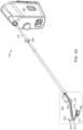
- Figs. 2A and 2Billustrate an example implementation of a medical instrument 110.
- Fig. 2Aparticularly shows a perspective view of an implementation having a tool 112 at the distal end of instrument shaft 114 and shows instrument shaft 114 extending from backend mechanism 116.
- distal tool 112 and instrument shaft 114have six degrees of freedom of movement relative to backend mechanism 116.
- the six degrees of freedomcorrespond to: pitch and yaw rotations of a distal portion of tool 112 about two respective perpendicular axes 201 and 202 associated with a first joint mechanism 211 (also called “first joint 211”); pitch and yaw rotations or movement of jaws 213 relative to two respective perpendicular axes 203 and 204 associated with a second joint mechanism 212 (also called “second joint 212"; the joints 211,212 are sometimes referred to as “wrists”); opening or closing movement 205 of jaws 213 for "grip” actuation; and "roll” rotations of instrument shaft 114 about its central length axis 206.
- Other instrumentsmay have more, fewer, or different degrees of freedom of movement.
- Backend mechanism 116 as shown in Fig. 2Bhas six input spindles 221 to 226 with engagement features that are shaped and positioned to engage actuators, e.g., drive motors, in a docking port of a robot.
- actuatorse.g., drive motors
- each input spindle 221 to 226may be coupled for actuation of a different degree of freedom of movement of the instrument, so that the robot can identify and use the correct actuator or actuators to rotate the spindle or spindles that exercise desired degrees of freedom of motion.
- the assignment input spindles 221 to 226 to corresponding degrees of freedommust be known to the robot but can be otherwise defined by an arbitrary standard or convention.
- input spindle 226may couple to a roll mechanism that connects to a proximal end of instrument shaft 114 for rotation of instrument shaft 114 about its length axis 206 when input spindle 226 rotates.
- Input spindles 221 to 225may couple to drive members (not shown) such as cables or rods extending though instrument shaft 114 to distal tool 112, so that the actuators in the robot can rotate input spindles 221 to 225 to control a distal mechanism including joints 211 and 212 and jaws 213. More specifically, in an exemplary implementation, rotation of input spindle 221 may control rotation or actuation of a distal portion of tool 112 about an axis 201.
- Rotation of input spindle 222may control rotation about an axis 202.
- Rotation of input spindle 223may control rotation about an axis 203 for yaw actuation of jaws 213, and rotation of input spindle 224 may control rotation about an axis 204 for pitch actuation of jaws 213.
- rotations of input spindles 221 to 226may correspond to motion that is different from or more complex than simple rotations of structures about axes.
- input spindle 225may be coupled to jaws 213 through a push-pull rod for actuation of gripping with jaws 213.
- the mechanism in tool 112may couple a proximal portion of joint 212 to a distal portion of joint 211 for parallelogram motion, while the distal portion of joint 212 may move independently.
- Fig. 3shows selected elements within an implementation of the backend mechanism 116 of Figs. 2A and 2B and particularly illustrates a routing in backend mechanism 116 of cables that run through instrument shaft 114 and connect to joints 211 and 212.
- the term "cable"is used herein in a broad sense to include any tendon-like structure.
- a length of cable in a medical instrumentmay include sections of different materials or different characteristics.
- a cablemay include, for example, a stranded section where flexibility in the cable is desired (e.g., where the cable winds around a spindle, capstan, or pulley) and may include a more rigid section (e.g., a tube or rod) to limit stretching where less bending of the cable is needed.
- Fig. 3shows selected elements within an implementation of the backend mechanism 116 of Figs. 2A and 2B and particularly illustrates a routing in backend mechanism 116 of cables that run through instrument shaft 114 and connect to joints 211 and 212.
- Input spindles 221, 222, 223, and 224are for actuation of degrees of freedom associated with respective axes 201, 202, 203, and 204, and each input spindles 221, 222, 223, and 224 includes a pair of capstans around which a pair of actuation cables are wrapped.
- an upper capstan 231A and a lower capstan 231Bmay be fixed on an axle of input spindle 221 so that both capstans 231A and 231B rotate with rotation of input spindle 221.
- the terms upper and lowerare used here to distinguish levels and may only apply literally when instrument shaft 114 points in a generally downward direction, as illustrated in Fig.
- a cable 241Awraps in one direction (e.g., clockwise or counterclockwise) around capstan 231A, and a cable 241B wraps in the opposite direction (e.g., counterclockwise or clockwise) around capstan 231B.
- Cable 241Aextends from upper capstan 231A to an upper pulley 251 that directs cable 241A toward instrument shaft 114.
- cable 241Bextends from lower capstan 231B to a lower pulley 261 that directs cable 241B toward instrument shaft 114.
- Cables 241A and 241Bextend from respective pulleys 251 and 261 through a guide 280, into instrument shaft 114, and through instrument shaft 114 to connect to actuated joint mechanism 211, so that pulling cable 241A or 242B rotates a distal portion of mechanism 211 (and distal portions of tool 112) about axis 201.
- the positions of pulleys 251 and 261 and the shape of guide 280may position cables 241A and 241B on opposite sides of the center or length axis 206 of instrument shaft 114, which may allow cable 241A to efficiently drive motion of mechanism 211 in one direction or sense about axis 201 and also allow cable 241B to efficiently drive motion of mechanism 211 in an opposite direction or sense about axis 201.
- Each input spindle 222, 223, or 224similarly includes an axle through a pair of capstans 232A and 232B, 233A and 233B, or 234A and 234B around which a pair of cables 242A and 242B, 243A and 243B, or 244A and 244B wrap in opposite directions, and cables 242A, 242B, 243A, 243B, 244A, and 244B pass over respective pulleys 252, 262, 253, 263, 254, and 264 and run through guide 280 and instrument shaft 114.
- cables 242A and 242Bconnect to joint mechanism 211
- cables 243A, 243B, 244A, and 244Bconnect to joint mechanism 212.
- Each pair of cables 242A and 242B, 243A and 243B, and 244A and 244B as described aboveincludes one cable wound in one direction (e.g., clockwise) about an input spindle 221, 222, 223, or 224 and another cable wound in the other direction (e.g., counterclockwise) around the input spindle 221, 222, 223, or 224, so that rotation of an input spindle 221, 222, 223, or 224 pulls in one cable while paying out another cable.
- one directione.g., clockwise
- another cable wound in the other directione.g., counterclockwise
- instrument 110may employ self-antagonistic actuation in which each pair of cables 241A and 241B, 242A and 242B, 243A and 243B, or 244A and 244B controls a corresponding degree of freedom of movement, e.g., rotations about axes 201, 202, 203, or 204, of the instrument.
- Non-antagonistic cable actuationmay be used in some embodiments (e.g., one cable per spindle).
- mechanisms 211 and 212are wrists or joints that each provide two degrees of freedom of movement. Many other mechanisms can provide one or more degrees of freedom of movement and may be connected so that one or more pairs of cables can respectively actuate the one or more degrees of freedom.
- An actuated mechanismmay, for example, include a mechanical linkage with a link that is rotatable about a pivot, and a pair of cables may be connected to rotate the link in opposite directions relative to the pivot.
- actuated mechanismsmay be any structure, e.g., a linkage, a slide, or a flexure, capable of being moved/actuated in opposite directions. For each pair of cables, pulling one cable may drive actuation of the corresponding degree of freedom in one direction or sense, and pulling the other cable in the pair may drive actuation of the corresponding degree of freedom in an opposite direction or sense.
- Routing of cables 241A, 242A, 243A, and 244Aemploys upper pulleys 251, 252, 253, and 254 to receive cables 241A, 242A, 243A, and 244A from upper capstans 231A, 232A, 233A, and 234A and employs lower pulleys 261, 262, 263, and 264 to receive cables 241B, 242B, 243B, and 244B from respective lower capstans 231B, 232B, 233B, and 234B.
- Upper pulleys 251, 252, 253, and 254may all be positioned at about the same common height, while lower pulleys 261, 262, 263, and 264 may all be positioned at about another common height that differs from the common height of upper pulleys 251, 252, 253, and 254. This allows the pulleys to be captured in stacked blocks or chassis pieces as described further below.
- upper pulleys 251, 252, 253, and 254 and lower pulleys 261, 262, 263, and 264may also be simplified by pairing pulleys to independently spin on shared axles. Using pulleys that share an axle may allow faster assembly, because multiple pulleys can be added to a structure by attaching a single axle.
- input spindles 221, 222, 223 and 224are arranged in a rectangular array, e.g., in rows and columns, and paths of cables from input spindles in the same row to locations over instrument shaft 114 are roughly parallel.
- pulleys 251 and 253, which guide cables 241A and 243A running at the same height and substantially the same direction from input spindles 221 and 223,can be mounted on a common axle 271.
- upper pulleys 252 and 254, which guide cables 242A and 244A that emerge from input spindles 222 and 224 with substantially the same height and directioncan be mounted on a shared axle 272.
- Lower pulleys 262 and 264, which guide cables 242B and 244B that emerge from input spindles 222 and 224 with substantially the same height and direction,can be mounted on another shared axle (not visible in Fig. 3 ), and lower pulleys 261 and 263, which guide cables 241B and 243B that emerge from input spindles 222 and 224 with substantially the same path and direction can be mounted on yet another shared axle 274.
- Pulley axles 271 to 274may also be angled according to exit directions of the cables from the input spindles 221 to 224 and relative to the central axis 206 of instrument shaft 114.
- axle 271may be turned about a first axis (e.g., an axis parallel to the axles of input spindles 221 to 224) to minimize the fleet angles at pulleys 251 and 253 of cables 241A and 243A from input spindles 221 and 223.
- Axle 271may be turned about a second axis (e.g., an axis approximately parallel to the portion of cables 241A and 243A between pulleys 251 and 253 and capstans 231A and 233A) so that the portion of cables 241A and 243A between pulleys 251 and 253 and guide 280 converge toward guide 280 and instrument shaft 114.
- the angling of axles 271 to 274may reduce the average fleet angle for entry and exit of the cables from the upper and lower pulleys and thereby reduce friction and wear.
- Axles 271 to 274may further be positioned relative to input spindles 221 to 224 and instrument shaft 114 to minimize wrap angles across sliding surfaces on the pulleys.
- the positions of the pulleysmay be further refined according to the desired cable paths exiting guide 280. In particular, redirection of any cable passing through guide 280 should only cause rubbing on the resilient surface (e.g., a metal portion) of guide 280 and not a softer surface (e.g., a plastic portion) of guide 280.
- the wrap angle across guide 280should also be small so that the friction and sawing action any cable against guide 280 is small.
- the cable pathshould further be relatively direct so that length of stranded cable does not negatively affect the overall stiffness of the drive train between the corresponding input spindle and the actuated mechanism.
- the stranded sections of cablestend to stretch more than the rigid hypotube sections used in some embodiments.
- the separations between input spindles 221 to 224may be considerably larger than the diameter of instrument shaft 114 into which the cables need to be directed. Accordingly, the paths of the cables need to converge between input spindles 221 to 225 and instrument shaft 114. The cables also should not rub against each other or against any other structures in backend mechanism 116.
- cables 241A, 241B, 242A, 242B, 243A, 243B, 244A, and 244B around the input spindles in the illustrated implementationare chosen so that cables at one level (e.g., lower cables 241B, 242B, 243B and 244B) emerge from inside the array of input spindles 221 to 224, and cables at other levels(e.g., upper cables 241A, 242A, 243A and 244A) emerge from an outer edge of the array of input spindles.
- cables at one levele.g., lower cables 241B, 242B, 243B and 244B
- cables at other levelse.g., upper cables 241A, 242A, 243A and 244A
- Lower cables 241B, 242B, 243B and 244Bwhich emerge from inside an area of the input spindle array, can directly converge at a relatively small angles toward instrument shaft 114 without interfering with each other or rubbing against other structures, such as input spindles 223 or 224.
- Upper cables 241A, 242A, 243A and 244Awhich emerge from the outer edge of input spindles 221 to 224, have crossing paths, which increases the angle of convergence.
- upper cables 241A and 243Awhich emerge from input spindles 221 and 223, cross over upper cables 242A and 244A, which emerge from input spindles 222 and 224.
- upper pulleys 251 and 253, which are within the same level group as upper pulleys 252 and 254, although having a generally common heightmay be staggered in height (e.g., so that cables 241A and 243A can cross over cables 242A and 244A without rubbing).
- the larger angle of convergence provided by the crossing patternallows cables 241A and 242A to pass from outer edges of input spindles 221 and 222 through the gap between input spindles 223 and 224.
- the crossing patternalso allows pulleys 251 and 253, which receive cables 241A and 243A, to be farther from pulleys 252 and 254, which receive cables 242A and 244A, than pulleys 261 and 263 are from pulleys 262 and 264.
- the wider spacing of upper pulleys 251 to 254allows routing cables 241A to 244A toward instrument shaft 114 without interference from lower pulleys 261 to 264 or cables 241B to 244B.
- Crossing one level of cables in this fashionalso allows positioning of cables that wrap about the same input spindle and that are therefore paired for actuation of the same degree of freedom in opposition in instrument shaft 114, which may permit efficient connection of the pair of cables to an actuated mechanism.
- the cable routing in the implementation of Fig. 3may provide several advantages.
- the difference in the horizontal separation of upper pulleys 251 to 254 from the horizontal separation of lower pulleys 261 to 264may allow upper pulleys 251 to 254 to be vertically positioned closer to lower pulleys 261 to 264, e.g., at a vertical separation that is less than the diameter of pulleys 251 to 254 and 261 to 264.
- upper pulleys 251 to 254 and lower pulleys 261 to 264may be at the same distance from the closest input spindles 223 and 224.
- a crossing cable patternmay further reduce the space needed to accommodate the required splay.
- the cable routingcan position pulleys so that the cables do not rub on each other or on neighboring input spindles and do not require additional intermediary idler pulleys.
- Fig. 4shows a cross-sectional view of internal structure in an example implementation of a backend mechanism 116.
- backend mechanism 116may include a chassis 500 with a central support structure 410 that extends between rows of input spindles 221, 222, 223, and 224.
- the routing of cables 241A to 244A or 241B to 244Ballows use of central support structure 410 to strengthen chassis 500 without interfering with cables 241A to 244A or 241B to 244B.
- the cable routingalso causes cables 241A to 244A or 241B to 244B to converge sufficiently to pass between input spindles 225 and 226, through an opening in a linkage 420 for actuation of jaws 213, and through an opening in a linkage 430 used for actuation of rotation about instrument shaft axis 206.
- This configuration with support structure 410 in the center of backend mechanism 116opens up access to input spindles 221, 222, 223, and 224 from around the perimeter of chassis 500, for example, to attach and wrap cables 241A to 244A or 241B to 244B on capstans 231A to 234A and 231B to 234B and to tighten capstan clamping screws during assembly of backend mechanism 116.
- Fig. 5shows an expanded view of some of the components in an implementation of a medical instrument with a multi-piece chassis 500 for a backend mechanism 116.
- Chassis 500includes pieces 510, 520, 530, 540, 550 and 560 that may be snapped together during an assembly process.
- a proximal end of instrument shaft 114may be inserted in a bearing system in chassis piece 510, at which point cables, e.g., cables 241A to 244A and 241B to 244B, which are attached to the distal tool of the instrument extend from instrument shaft 114.
- chassis piece 520may be attached to chassis piece 510 so that guide 280 is captured between chassis pieces 510 and 520. All or portions of grip or roll gears or mechanisms that couple to input spindles 225 or 226 may also be assembled on chassis pieces 510 and 520 before chassis pieces 510 and 520 are snapped together and may be held in place by chassis pieces 510 and 520.
- An upper portion of chassis piece 520further includes central support structure 410, which is described above and includes features 524 shaped to hold lower capstans 231B to 234B which will be mounted on input spindles 221 to 224.
- Chassis pieces 530 and 520are separate to allow for the assembly of linkage 420 that couples to input spindle 525 and is employed for grip actuation in the exemplary implementation.
- Chassis piece 530has an upper portion shaped to hold axles 273 and 274 for lower pulleys that guide the actuation cables and redirect the actuation cables toward the instrument shaft. As shown in Fig. 6A , lower pulleys 263 and 261 on axle 273 may be mounted in slots formed in chassis piece 530. Similarly, lower pulleys 262 and 264 on axle 274 are mounted in another set of slots in chassis piece 530.
- Lower cables 241B, 242B, 243B, and 244Bwhich extend from instrument shaft 114, may be seated in grooves on respective lower pulleys 261, 262, 263, and 264 and threaded through openings in chassis piece 530 so that proximal ends of lower cables 241B, 242B, 243B, and 244B are near features 524 where input spindles 221 to 224 will reside.
- Chassis piece 530 and 540may be shaped to provide a close fit between chassis piece 540 and pulleys 261 to 264 so that cables 241B, 242B, 243B, and 244B are not easily derailed.
- Upper pulleys 251 and 253 on axle 272 and upper pulleys 252 and 254 on axle 271may be mounted in slots created by the combination of chassis pieces 530 and 540. The slot into which axle 271 fits may be at slightly different level from the slot into which axle 272 fits so that the upper cables can cross as described above.
- Upper cables 241A, 242A, 243A, and 244Amay be seated on respective upper pulleys 251, 252, 253, and 254 and threaded through openings in chassis 500 so that proximal ends of upper cables 241A, 242A, 243A, and 244A are also near features 524.
- a chassis piece 550connects to chassis pieces 530 and 540 as shown in Fig. 6C and may be shaped to provide a close fit to upper pulleys 251 to 254 so that upper cables 241A, 242A, 243A, and 244A are not easily derailed.
- 6Dparticularly shows a cross-sectional view illustrating how chassis piece 550 when mounted on pieces 530 and 540 may be close fit to pulley 251 so that a gap 545 between chassis piece 550 and pulley 251 is narrower than the thickness of cable 241A on pulley 251.
- cable 241Afits into the grove in pulley 251 and cannot slip through gap 545.
- a chassis piece 560snaps onto or otherwise connects to one or more of chassis pieces 520, 530, and 550.
- the top of chassis piece 560is shaped to fit a docking port of a robot and includes features 564 that are shaped and located to hold the engagement features of input spindles 221 to 224 of the instrument.
- chassis 500may capture input spindles 221 to 224 between features 564 on chassis piece 560 and features 524 on chassis piece 520.
- Each input spindlemay include an axle and a pair of capstans, e.g., upper capstans 231A to 234A and lower capstans 231B to 234B, which are initially free to rotate relative to each other.
- the loose proximal ends of the actuation cables near features 524may be attached to the corresponding one of capstans 231A to 234A or 231B to 234B.
- Each capstancan then be independently rotated to wind the attached cable in the desired direction and to take up slack and provide a desired pre-tension in the attached cable.
- the capstanscan be clamped or locked in place on the axle of the input spindle, e.g., by tightening a clamping screw.
- Other structuressuch as release levers comprising structure 440 of Fig. 4 may wrap around the outside of the actuation structure and cables and may be installed after assembly of the input spindles and routing of cables.
- Co-filed U.S. Pat. App. No. 62/362,454(filed Jul. 14, 2016 ), entitled “INSTRUMENT RELEASE”, describes structures such as release levers comprising structure 440 in more detail.
- the instrument assembly and cable routing process illustrated by Figs. 5 and 6A to 6Dmay be relatively simple when compared to the complexity of the instrument.
- achieving the desired cable routingdoes not require simultaneous threading of cables through and around a complex sequence of structures from which the cables may slip. Instead, assembly can proceed in a series of simple steps with the cables being in a secure configuration after each step.
- the shape of the chassisprovides good access to input spindles for cable connections.
Landscapes
- Health & Medical Sciences (AREA)
- Surgery (AREA)
- Engineering & Computer Science (AREA)
- Life Sciences & Earth Sciences (AREA)
- Medical Informatics (AREA)
- Robotics (AREA)
- Biomedical Technology (AREA)
- Heart & Thoracic Surgery (AREA)
- Nuclear Medicine, Radiotherapy & Molecular Imaging (AREA)
- Molecular Biology (AREA)
- Animal Behavior & Ethology (AREA)
- General Health & Medical Sciences (AREA)
- Public Health (AREA)
- Veterinary Medicine (AREA)
- Manipulator (AREA)
- Flexible Shafts (AREA)
Description
- Robotically controlled instruments such as employed for minimally invasive medical procedures often employ a tool or end effector or other manipulation element at the distal end of an extended instrument shaft. (As used herein, the terms "robot" or "robotically" and the like include teleoperation or telerobotic aspects.) The instrument shaft and the distal tool generally have small diameters, often less than a centimeter, to minimize the size of incisions or natural lumens needed for insertion of the instrument. Accordingly, the distal tools are often remotely operated or actuated via thin drive members (e.g., tendons or rods) that extend between the distal tool and a transmission, sometimes referred to as the backend mechanism of the instrument. The backend mechanism of a replaceable instrument is generally configured to removably couple to actuators (e.g., a motor pack) in a docking port of a robot. The robot can then control the actuators and apply force through the backend mechanism to the drive members and through the drive members to the distal tool of the instrument.
- Medical instruments that have many degrees of freedom of movement typically require many drive members, and backend mechanisms that accommodate the transition from the layout of a docking port of a robot to the layout of the drive members in the instrument shaft can be complex and difficult to assemble.
- Reference D1 (
EP 2640301 B1 ) discloses surgical assemblies and related methods that provide for decoupling of instrument shaft roll and end effector actuation. The surgical assembly includes a base, an instrument shaft rotationally mounted to the base, an end effector supported at a distal end of the instrument shaft and including an actuation mechanism driven by a rotational motion, a drive shaft rotationally coupled with the actuation mechanism and configured to provide the rotational motion to the actuation mechanism, and a differential rotationally coupled to the drive shaft and receiving a first input motion and a second input motion. The differential combines the first and second input motions to generate an output motion that rotates the drive shaft. The first input motion is rotationally coupleable to an actuation source. The second input motion is coupled to rotation of the instrument shaft relative to the base. - Reference D2 (
US 2010/011900 A1 ) describes a medical instrument guiding two sets of cables respectively through a first and a second set of pulleys into an instrument shaft to deflect a wrist mechanism. - The invention is defined by the appended independent claims 1 and 7. Further embodiments of the invention are illustrated in the dependent claims.
- In accordance with an aspect of the disclosure, a medical instrument may provide efficient routing of actuation cables and relatively simple assembly process for complex medical instruments.
- One specific implementation provides a medical instrument including a chassis, input spindles mounted in the chassis, upper and lower cables wound around the input spindles, and an instrument shaft extending from the chassis and including a mechanical structure providing multiple degrees of freedom of motion. The upper and lower cables may connect to the mechanical structure so that rotations of the input spindles actuate respective degrees of freedom. Lower pulleys may be mounted at a first level to receive the lower cables from the input spindles and to redirect the lower cables toward the instrument shaft. Upper pulleys may be mounted at a second level to receive the upper cables from the input spindles and redirect the upper cables through the first level and toward the instrument shaft.
- Another specific implementation is a method for assembling a medical instrument. The method may include: mounting lower pulleys on a first piece of a chassis of the medical instrument; feeding lower cables from an instrument shaft of the medical instrument over the lower pulleys; attaching a second piece of the chassis to the first piece so that at least portions of the lower cables are between the lower pulleys and the second piece; mounting upper pulleys in positions such that the second piece is between the upper pulleys and the lower pulleys; and feeding upper cables from the instrument shaft over the upper pulleys.
- Yet another specific implementation is a medical instrument including input spindles, lower cables respectively wound around the input spindles, upper cables respectively wound around the input spindles, and an instrument shaft extending from a chassis in which the input spindles are mounted. A mechanical structure on the instrument shaft has multiple degrees of freedom of motion, and the upper and lower cables connect to the structure such that rotations the input spindles respectively actuate the degrees of freedom. The lower or upper cables may extend between the input spindles and the instrument shaft without crossing, and paths of the other upper or lower cables cross between the input spindles and the instrument shaft. The crossing in one set of cables may allow the upper cable and the lower cable that wrap around the same input spindle to be more efficiently directed toward locations on opposite sides of a central axis of the instrument shaft, which may improve mechanical efficiency of actuation of the mechanical structure.
Fig. 1 shows an implementation of a medical system employing removable instruments.Figs. 2A and2B show side and top views of an example implementation of a medical instrument.Fig. 3 shows cable routing in an example implementation of a backend mechanism of a medical instrument.Fig. 4 is a cross-sectional view illustrating a routing of cables relative to a chassis and other structures in an example implementation of a backend mechanism of a medical instrument.Fig. 5 is an expanded view of an implementation of a medical instrument including a backend mechanism with a multi-piece chassis.Figs. 6A, 6B, and 6C illustrate a pulley structure created during an assembly process for a backend mechanism that routes cables between an instrument shaft of a medical instrument and a set of input spindles around which the cables wrap.Fig. 6D shows a cross-section of a portion of an example implementation of a backend mechanism and illustrates how pieces of a chassis may be fit close to a pulley to prevent cable derailment.- The drawings illustrate examples for the purpose of explanation and are not of the invention itself. Use of the same reference symbols in different figures indicates similar or identical items.
- A backend mechanism of a robotically controlled medical instrument routes cables from multiple input spindles to an instrument shaft of the instrument and employs a routing that allows simple assembly using few components. Cables and associated pulleys in an instrument may be particularly grouped by level or height relative to the instrument shaft, and lower cables may be fit on pulleys mounted in a lower chassis piece before a next, higher chassis piece and pulleys for upper cables are attached to the lower chassis piece. A two-level system is particularly effective in a self-antagonistic system in which each input spindle has a pair of two associated cables that are wrapped around the input spindle in opposite directions and at different heights so that one cable pays in in one direction and the other cable pays out in an opposite direction as the spindle rotates. The cable routing leaves space for other components of the backend of a medical instrument, for example, to allow control or actuation of instrument shaft roll, grip drive, electrical connectors, and latching mechanisms that attach the backend mechanism to a robot. The cable routing can also position cables paired in opposition in the instrument shaft, so that the paired cables can efficiently actuate opposite directions of motion of a degree of freedom of the instrument.
Fig. 1 shows an example of amedical system 100 using replaceablemedical instruments 110.System 100, which may, for example, be a da Vinci® Surgical System commercialized by Intuitive Surgical, Inc., may particularly employ multiplesurgical instruments 110, each of which is removably mounted in adocking port 120 on amanipulator arm 130 of arobot 140. A sterile barrier (not shown) including a drape and adaptors forinstruments 110 may be betweeninstruments 110 androbot 140, so thatrobot 140, includingmanipulator arms 130 anddocking ports 120, is outside a sterile environment for a patient. Accordingly,robot 140 may not need to be sterilized between medical procedures. In contrast,instruments 110, which may be used in the sterile environment and may contact the patient, are compact and removable so thatinstruments 110 may be sterilized or replaced between medical procedures performed usingsystem 100.Instruments 110 may vary in structure and purpose but may still be interchangeable, so thatinstruments 110 mounted indocking ports 120 ofrobot 140 can be selected for a particular medical procedure or changed during a medical procedure to provide the clinical functions needed. Eachinstrument 110 generally includes an end effector ordistal tool 112, aninstrument shaft 114, and abackend mechanism 116.Distal tools 112 may have different designs to implement many different functions. For example,distal tools 112 fordifferent instruments 110 may have many different shapes or sizes and may include forceps, graspers, scalpels, scissors, cautery tools, or needle drivers to name a few possibilities, andinstruments 110 having differentdistal tools 112 may be mounted ondifferent arms 130 ofrobot 140 and may work cooperatively in the same work site. An endoscopic camera, for example, a stereoscopic camera, can also be mounted on an arm to provide visual information, particularly images, of the work site in whichdistal tools 112 ofinstruments 110 may be operating.Docking ports 120 may include actuators, such as drive motors, that provide mechanical power for actuation of mechanical structures ininstruments 110, drive couplings that connect the actuators to inputs ofinstruments 110, and systems for establishing and maintaining a sterile barrier betweeninstruments 110 and the rest ofmedical system 100.Docking ports 120 may additionally include an electrical interface to provide power toinstruments 110 or for communication withinstruments 110, for example, to identify the type ofinstrument 110 in adocking port 120, to access parameters ofinstruments 110, or to receive information from sensors ininstruments 110. For example, the electrical interface may convey to robot 140 measurements such as measurements of the position, orientation, or pose ofdistal tool 112 andinstrument shaft 114 of aninstrument 110. A computer system, which may be connected to or part ofrobot 140 and connected to a user interface device (not shown), may receive the measurements frominstrument 110 and receive user commands from a surgeon or other medical personnel and may execute software that controlsarms 130 and drive motors indocking ports 120 as needed to operateinstruments 110 according to the user commands.Figs. 2A and2B illustrate an example implementation of amedical instrument 110.Fig. 2A particularly shows a perspective view of an implementation having atool 112 at the distal end ofinstrument shaft 114 and showsinstrument shaft 114 extending frombackend mechanism 116. In the illustrated implementation,distal tool 112 andinstrument shaft 114 have six degrees of freedom of movement relative tobackend mechanism 116. In particular, the six degrees of freedom correspond to: pitch and yaw rotations of a distal portion oftool 112 about two respectiveperpendicular axes jaws 213 relative to two respectiveperpendicular axes closing movement 205 ofjaws 213 for "grip" actuation; and "roll" rotations ofinstrument shaft 114 about itscentral length axis 206. Other instruments may have more, fewer, or different degrees of freedom of movement.Backend mechanism 116 as shown inFig. 2B has sixinput spindles 221 to 226 with engagement features that are shaped and positioned to engage actuators, e.g., drive motors, in a docking port of a robot. In general, eachinput spindle 221 to 226 may be coupled for actuation of a different degree of freedom of movement of the instrument, so that the robot can identify and use the correct actuator or actuators to rotate the spindle or spindles that exercise desired degrees of freedom of motion. Theassignment input spindles 221 to 226 to corresponding degrees of freedom must be known to the robot but can be otherwise defined by an arbitrary standard or convention. In an exemplary implementation,input spindle 226 may couple to a roll mechanism that connects to a proximal end ofinstrument shaft 114 for rotation ofinstrument shaft 114 about itslength axis 206 wheninput spindle 226 rotates.Input spindles 221 to 225 may couple to drive members (not shown) such as cables or rods extending thoughinstrument shaft 114 todistal tool 112, so that the actuators in the robot can rotateinput spindles 221 to 225 to control a distalmechanism including joints jaws 213. More specifically, in an exemplary implementation, rotation ofinput spindle 221 may control rotation or actuation of a distal portion oftool 112 about anaxis 201. Rotation ofinput spindle 222 may control rotation about anaxis 202. Rotation ofinput spindle 223 may control rotation about anaxis 203 for yaw actuation ofjaws 213, and rotation ofinput spindle 224 may control rotation about anaxis 204 for pitch actuation ofjaws 213. In some implementations, rotations ofinput spindles 221 to 226 may correspond to motion that is different from or more complex than simple rotations of structures about axes. For example,input spindle 225 may be coupled tojaws 213 through a push-pull rod for actuation of gripping withjaws 213. Also, in a particular implementation, the mechanism intool 112 may couple a proximal portion of joint 212 to a distal portion of joint 211 for parallelogram motion, while the distal portion of joint 212 may move independently.Fig. 3 shows selected elements within an implementation of thebackend mechanism 116 ofFigs. 2A and2B and particularly illustrates a routing inbackend mechanism 116 of cables that run throughinstrument shaft 114 and connect tojoints Fig. 3 does not show elements ofbackend mechanisms 116 that may be used for actuation of degrees of freedom associated with rotation ofinstrument shaft 114 or for opening and closing ofjaws 213. Co-filedU.S. Pat. App. No. 62/362,340 (filed Jul. 14, 2016 U.S. Pat. App. No. 62/362,365 (filed Jul. 14, 2016 Input spindles respective axes Fig. 3 , anupper capstan 231A and alower capstan 231B may be fixed on an axle ofinput spindle 221 so that bothcapstans input spindle 221. (The termsupper andlower are used here to distinguish levels and may only apply literally wheninstrument shaft 114 points in a generally downward direction, as illustrated inFig. 3 .) Acable 241A wraps in one direction (e.g., clockwise or counterclockwise) aroundcapstan 231A, and acable 241B wraps in the opposite direction (e.g., counterclockwise or clockwise) aroundcapstan 231B.Cable 241A extends fromupper capstan 231A to anupper pulley 251 that directscable 241A towardinstrument shaft 114. Similarly,cable 241B extends fromlower capstan 231B to alower pulley 261 that directscable 241B towardinstrument shaft 114.Cables respective pulleys guide 280, intoinstrument shaft 114, and throughinstrument shaft 114 to connect to actuatedjoint mechanism 211, so that pullingcable axis 201. The positions ofpulleys guide 280 may positioncables length axis 206 ofinstrument shaft 114, which may allowcable 241A to efficiently drive motion ofmechanism 211 in one direction or sense aboutaxis 201 and also allowcable 241B to efficiently drive motion ofmechanism 211 in an opposite direction or sense aboutaxis 201.- Each
input spindle capstans cables cables respective pulleys guide 280 andinstrument shaft 114. In an exemplary implementation,cables joint mechanism 211, andcables joint mechanism 212. - Each pair of
cables input spindle input spindle input spindle instrument 110 may employ self-antagonistic actuation in which each pair ofcables axes - In the illustrated system,
mechanisms - Routing of
cables upper pulleys cables upper capstans lower pulleys cables lower capstans Upper pulleys lower pulleys upper pulleys - The arrangement of
upper pulleys lower pulleys Fig. 3 ,input spindles instrument shaft 114 are roughly parallel. Accordingly, pulleys 251 and 253, which guidecables input spindles common axle 271. Similarly,upper pulleys cables input spindles axle 272.Lower pulleys cables input spindles Fig. 3 ), andlower pulleys cables input spindles axle 274. - Pulley axles 271 to 274 may also be angled according to exit directions of the cables from the
input spindles 221 to 224 and relative to thecentral axis 206 ofinstrument shaft 114. For example,axle 271 may be turned about a first axis (e.g., an axis parallel to the axles ofinput spindles 221 to 224) to minimize the fleet angles atpulleys 251 and 253 ofcables input spindles Axle 271 may be turned about a second axis (e.g., an axis approximately parallel to the portion ofcables pulleys 251 and 253 andcapstans cables pulleys 251 and 253 and guide 280 converge towardguide 280 andinstrument shaft 114. The angling ofaxles 271 to 274 may reduce the average fleet angle for entry and exit of the cables from the upper and lower pulleys and thereby reduce friction and wear. Axles 271 to 274 may further be positioned relative to inputspindles 221 to 224 andinstrument shaft 114 to minimize wrap angles across sliding surfaces on the pulleys. The positions of the pulleys may be further refined according to the desired cablepaths exiting guide 280. In particular, redirection of any cable passing throughguide 280 should only cause rubbing on the resilient surface (e.g., a metal portion) ofguide 280 and not a softer surface (e.g., a plastic portion) ofguide 280. The wrap angle acrossguide 280 should also be small so that the friction and sawing action any cable againstguide 280 is small. The cable path should further be relatively direct so that length of stranded cable does not negatively affect the overall stiffness of the drive train between the corresponding input spindle and the actuated mechanism. In general, the stranded sections of cables tend to stretch more than the rigid hypotube sections used in some embodiments.- The separations between
input spindles 221 to 224 may be considerably larger than the diameter ofinstrument shaft 114 into which the cables need to be directed. Accordingly, the paths of the cables need to converge betweeninput spindles 221 to 225 andinstrument shaft 114. The cables also should not rub against each other or against any other structures inbackend mechanism 116. To avoid cable interference, the winding directions ofcables lower cables input spindles 221 to 224, and cables at other levels(e.g.,upper cables Lower cables instrument shaft 114 without interfering with each other or rubbing against other structures, such asinput spindles Upper cables input spindles 221 to 224, have crossing paths, which increases the angle of convergence. In particular,upper cables input spindles upper cables input spindles upper pulleys 251 and 253, which are within the same level group asupper pulleys cables cables cables input spindles input spindles pulleys 251 and 253, which receivecables pulleys cables pulleys pulleys upper pulleys 251 to 254 allowsrouting cables 241A to 244A towardinstrument shaft 114 without interference fromlower pulleys 261 to 264 orcables 241B to 244B. Crossing one level of cables in this fashion also allows positioning of cables that wrap about the same input spindle and that are therefore paired for actuation of the same degree of freedom in opposition ininstrument shaft 114, which may permit efficient connection of the pair of cables to an actuated mechanism. - The cable routing in the implementation of
Fig. 3 may provide several advantages. In particular, the difference in the horizontal separation ofupper pulleys 251 to 254 from the horizontal separation oflower pulleys 261 to 264, may allowupper pulleys 251 to 254 to be vertically positioned closer tolower pulleys 261 to 264, e.g., at a vertical separation that is less than the diameter ofpulleys 251 to 254 and 261 to 264. Also,upper pulleys 251 to 254 andlower pulleys 261 to 264 may be at the same distance from theclosest input spindles Fig. 4 shows a cross-sectional view of internal structure in an example implementation of abackend mechanism 116. As illustrated,backend mechanism 116 may include achassis 500 with acentral support structure 410 that extends between rows ofinput spindles cables 241A to 244A or 241B to 244B allows use ofcentral support structure 410 to strengthenchassis 500 without interfering withcables 241A to 244A or 241B to 244B. The cable routing also causescables 241A to 244A or 241B to 244B to converge sufficiently to pass betweeninput spindles linkage 420 for actuation ofjaws 213, and through an opening in alinkage 430 used for actuation of rotation aboutinstrument shaft axis 206. This configuration withsupport structure 410 in the center ofbackend mechanism 116 opens up access toinput spindles chassis 500, for example, to attach and wrapcables 241A to 244A or 241B to 244B oncapstans 231A to 234A and 231B to 234B and to tighten capstan clamping screws during assembly ofbackend mechanism 116. Onceinput spindles chassis 500 andcapstans 231A to 234A and 231B to 234B are wrapped and clamped, the space aroundinput spindles structure 440, for latching backend mechanism to a docking port on a robot.Fig. 5 shows an expanded view of some of the components in an implementation of a medical instrument with amulti-piece chassis 500 for abackend mechanism 116.Chassis 500 includespieces instrument shaft 114 may be inserted in a bearing system inchassis piece 510, at which point cables, e.g.,cables 241A to 244A and 241B to 244B, which are attached to the distal tool of the instrument extend frominstrument shaft 114. The cables may then be fed through desired locations inguide 280, andchassis piece 520 may be attached tochassis piece 510 so thatguide 280 is captured betweenchassis pieces spindles chassis pieces chassis pieces chassis pieces chassis piece 520 further includescentral support structure 410, which is described above and includesfeatures 524 shaped to holdlower capstans 231B to 234B which will be mounted oninput spindles 221 to 224.- The assembly process can then connect
chassis piece 530 tochassis piece 520.Chassis pieces linkage 420 that couples to input spindle 525 and is employed for grip actuation in the exemplary implementation. Chassis piece 530 has an upper portion shaped to holdaxles Fig. 6A ,lower pulleys axle 273 may be mounted in slots formed inchassis piece 530. Similarly,lower pulleys axle 274 are mounted in another set of slots inchassis piece 530.Lower cables instrument shaft 114, may be seated in grooves on respectivelower pulleys chassis piece 530 so that proximal ends oflower cables features 524 whereinput spindles 221 to 224 will reside.- The assembly process can next connect a
chassis piece 540 tochassis piece 530 as shown inFig. 6B .Chassis piece chassis piece 540 andpulleys 261 to 264 so thatcables Upper pulleys 251 and 253 onaxle 272 andupper pulleys axle 271 may be mounted in slots created by the combination ofchassis pieces axle 271 fits may be at slightly different level from the slot into whichaxle 272 fits so that the upper cables can cross as described above.Upper cables upper pulleys chassis 500 so that proximal ends ofupper cables chassis piece 550 connects tochassis pieces Fig. 6C and may be shaped to provide a close fit toupper pulleys 251 to 254 so thatupper cables Fig. 6D particularly shows a cross-sectional view illustrating howchassis piece 550 when mounted onpieces pulley 251 so that agap 545 betweenchassis piece 550 andpulley 251 is narrower than the thickness ofcable 241A onpulley 251. As a result,cable 241A fits into the grove inpulley 251 and cannot slip throughgap 545. - Returning to
Fig. 5 , achassis piece 560 snaps onto or otherwise connects to one or more ofchassis pieces chassis piece 560 is shaped to fit a docking port of a robot and includesfeatures 564 that are shaped and located to hold the engagement features ofinput spindles 221 to 224 of the instrument. Whenchassis piece 560 attaches to theassembly including pieces chassis 500 may captureinput spindles 221 to 224 betweenfeatures 564 onchassis piece 560 and features 524 onchassis piece 520. Each input spindle may include an axle and a pair of capstans, e.g.,upper capstans 231A to 234A andlower capstans 231B to 234B, which are initially free to rotate relative to each other. The loose proximal ends of the actuation cables nearfeatures 524 may be attached to the corresponding one ofcapstans 231A to 234A or 231B to 234B. Each capstan can then be independently rotated to wind the attached cable in the desired direction and to take up slack and provide a desired pre-tension in the attached cable. Once both cables wrapped around an input spindle have the desired cable tensioning, the capstans can be clamped or locked in place on the axle of the input spindle, e.g., by tightening a clamping screw. Other structures such as releaselevers comprising structure 440 ofFig. 4 may wrap around the outside of the actuation structure and cables and may be installed after assembly of the input spindles and routing of cables. Co-filedU.S. Pat. App. No. 62/362,454 (filed Jul. 14, 2016 levers comprising structure 440 in more detail. - The instrument assembly and cable routing process illustrated by
Figs. 5 and6A to 6D may be relatively simple when compared to the complexity of the instrument. In particular, achieving the desired cable routing does not require simultaneous threading of cables through and around a complex sequence of structures from which the cables may slip. Instead, assembly can proceed in a series of simple steps with the cables being in a secure configuration after each step. Further, the shape of the chassis provides good access to input spindles for cable connections. - Although particular implementations have been disclosed, these implementations are only examples and should not be taken as limitations. Various adaptations and combinations of features of the implementations disclosed are within the scope of the following claims.
Claims (11)
- A medical instrument (110) comprising:a plurality of input spindles (221, 222, 223, 224);a plurality of first cables (241B, 242B, 243B, 244B);a plurality of second cables (241A, 242A, 243A, 244A), one of each cable of the first and second plurality of cables (241A, 242A, 243A, 244A, 241B, 242B, 243B, 244B) being wrapped around a corresponding input spindle of the plurality of input spindles (221, 222, 223, 224);a chassis (500) in which the plurality of input spindles (221, 222, 223, 224) is mounted;an instrument shaft (114) comprising a first end and a second end, the instrument shaft extending from the chassis at the first end;a mechanical structure (112) coupled to the second end of the instrument shaft (114), the mechanical structure (112) having a plurality of degrees of freedom of motion, the plurality of first cables and the second cables (241A, 242A, 243A, 244A, 241B, 242B, 243B, 244B) being connected to the mechanical structure (112) such that rotations the plurality of input spindles (221, 222, 223, 224) actuate the plurality of degrees of freedom;a plurality of first pulleys (261, 262, 263, 264) mounted at a first level on the chassis, the plurality of first pulleys (261, 262, 263, 264) receiving the plurality of first cables (241B, 242B, 243B, 244B) from the plurality of input spindles (221, 222, 223, 224) and redirecting the plurality of first cables (241B, 242B, 243B, 244B) into and through the instrument shaft (114); anda plurality of second pulleys (251, 252, 253, 254) mounted at a second level on the chassis different from the first level, the plurality of second pulleys (251, 252, 253, 254) receiving the plurality of second cables (241A, 242A, 243A, 244A) from the plurality of input spindles (221, 222, 223, 224) and redirecting the plurality of second cables (241A, 242A, 243A, 244A) through the first level and into and through the instrument shaft (114).
- The medical instrument (110) of claim 1, wherein the chassis comprises:a first piece (530) on which the plurality of first pulleys (261, 262, 263, 264) is mounted; anda second piece (540) mounted over the first piece (540) so that the plurality of first pulleys (261, 262, 263, 264) is located between the first piece (540) and the second piece (540), the second piece (540) being between the plurality of first pulleys (261, 262, 263, 264) and the plurality of second pulleys (251, 252, 253, 254).
- The medical instrument (110) of claims 1 or 2, wherein:the plurality of first cables (241B, 242B, 243B, 244B) extends between the plurality of input spindles (221, 222, 223, 224) and the plurality of first pulleys (261, 262, 263, 264) without crossing; anda first set of the plurality of second cables crosses a second set of the plurality of second cables between the plurality of input spindles and the plurality of second pulleys.
- The medical instrument (110) of claim 3, wherein:the plurality of input spindles (221, 222, 223, 224) is arranged in an array;each first cable of the plurality of first cables (241B, 242B, 243B, 244B) is wrapped about the corresponding input spindle (221, 222, 223, 224) in a direction such that a path of the first cable from the corresponding input spindle to the plurality of first pulleys (261, 262, 263, 264) emerges within the array; andeach second cable of the plurality of second cables (241A, 242A, 243A, 244A) is wrapped about the corresponding input spindle (221, 222, 223, 224) in a direction such that a path of the second cable from the corresponding input spindle to the plurality of second pulleys (251, 252, 253, 254) emerges from a perimeter of the array.
- The medical instrument (110) of claims 1 or 2, wherein:
for each corresponding input spindle of the plurality of input spindles (221, 222, 223, 224), the first cable wraps around the corresponding input spindle in a first direction, and the second cable wraps around the corresponding input spindle in a second direction opposite the first direction. - The medical instrument of claim 1, wherein:the plurality of second pulleys (251, 252, 253, 254) comprises a first upper pulley (251) and a second upper pulley (252);the first upper pulley (251) is rotatable about a first pulley axis (271);the second upper pulley (252) is rotatable about a second pulley axis (272); andthe first pulley axis (271) and the second pulley axis (272) axis are mounted at an angle relative to one another to reduce the average fleet angle for entry and exit of the cables from the first upper pulley (251) and the second upper pulley (252).
- A method for assembling a medical instrument (110) comprising:mounting a plurality of first pulleys (261, 262, 263, 264) on a first piece (530) of a chassis (500) of the medical instrument (110);feeding a plurality of first cables (241B, 242B, 243B, 244B) through an instrument shaft (114) of the medical instrument (110) over the plurality of first pulleys (261, 262, 263, 264);attaching a second piece (540) of the chassis (500) to the first piece (530) so that at least a portion of the plurality of first cables (241B, 242B, 243B, 244B) is between the plurality of first pulleys (261, 262, 263, 264) and the second piece (540);mounting a plurality of second pulleys (251, 252, 253, 254) on the chassis (500) in positions such that the second piece (540) is between the plurality of second pulleys (251, 252, 253, 254) and the plurality of first pulleys (261, 262, 263, 264); andfeeding a plurality of second cables (241A, 242A, 243A, 244A) through the instrument shaft (114) over the plurality of second pulleys (251, 252, 253, 254).
- The method of claim 7, wherein:
gaps between the second piece (540) and the plurality of first pulleys (261, 262, 263, 264) are narrower than a width of the plurality of first cables (241B, 242B, 243B, 244B). - The method of claims 7 or 8, further comprising:
attaching a third piece (550) of the chassis (500) to the first and second pieces (530, 540) so that at least a portion of the plurality of second cables (241A, 242A, 243A, 244A) is between the plurality of second pulleys (251, 252, 253, 254) and the third piece (550). - The method of claims of 7-9, further comprising:winding a first cable of the plurality of first cables (241B, 242B, 243B, 244B) around a lower portion of an input spindle; andwinding a second cable of the plurality of second cables (241A, 242A, 243A, 244A) around an upper portion of the input spindle, wherein the second cable and the first cable wrap around the input spindle in opposite directions.
- The method of claim 10, wherein winding the first cable (241B, 242B, 243B, 244B) around the input spindle (221, 222, 223, 224) comprises:winding the first cable (241B, 242B, 243B, 244B) on a first capstan (231B, 232B, 233B, 234B) until the first cable has a desired tension, andaffixing the first capstan (231B, 232B, 233B, 234B) on the input spindle (221, 222, 223, 224).
Priority Applications (1)
| Application Number | Priority Date | Filing Date | Title |
|---|---|---|---|
| EP24185507.1AEP4413942A3 (en) | 2016-07-14 | 2017-06-22 | Multi-cable medical instrument |
Applications Claiming Priority (2)
| Application Number | Priority Date | Filing Date | Title |
|---|---|---|---|
| US201662362431P | 2016-07-14 | 2016-07-14 | |
| PCT/US2017/038674WO2018013313A1 (en) | 2016-07-14 | 2017-06-22 | Multi-cable medical instrument |
Related Child Applications (1)
| Application Number | Title | Priority Date | Filing Date |
|---|---|---|---|
| EP24185507.1ADivisionEP4413942A3 (en) | 2016-07-14 | 2017-06-22 | Multi-cable medical instrument |
Publications (3)
| Publication Number | Publication Date |
|---|---|
| EP3484397A1 EP3484397A1 (en) | 2019-05-22 |
| EP3484397A4 EP3484397A4 (en) | 2020-07-22 |
| EP3484397B1true EP3484397B1 (en) | 2024-07-24 |
Family
ID=60953285
Family Applications (2)
| Application Number | Title | Priority Date | Filing Date |
|---|---|---|---|
| EP17828154.9AActiveEP3484397B1 (en) | 2016-07-14 | 2017-06-22 | Multi-cable medical instrument |
| EP24185507.1APendingEP4413942A3 (en) | 2016-07-14 | 2017-06-22 | Multi-cable medical instrument |
Family Applications After (1)
| Application Number | Title | Priority Date | Filing Date |
|---|---|---|---|
| EP24185507.1APendingEP4413942A3 (en) | 2016-07-14 | 2017-06-22 | Multi-cable medical instrument |
Country Status (5)
| Country | Link |
|---|---|
| US (3) | US11207145B2 (en) |
| EP (2) | EP3484397B1 (en) |
| KR (2) | KR102543919B1 (en) |
| CN (3) | CN119908844A (en) |
| WO (1) | WO2018013313A1 (en) |
Families Citing this family (27)
| Publication number | Priority date | Publication date | Assignee | Title |
|---|---|---|---|---|
| US10076348B2 (en) | 2013-08-15 | 2018-09-18 | Intuitive Surgical Operations, Inc. | Rotary input for lever actuation |
| US10550918B2 (en) | 2013-08-15 | 2020-02-04 | Intuitive Surgical Operations, Inc. | Lever actuated gimbal plate |
| WO2018013316A1 (en) | 2016-07-14 | 2018-01-18 | Intuitive Surgical Operations, Inc. | Geared roll drive for medical instrument |
| CN109414300B (en) | 2016-07-14 | 2021-11-09 | 直观外科手术操作公司 | Instrument flushing system |
| WO2018013298A1 (en) | 2016-07-14 | 2018-01-18 | Intuitive Surgical Operations, Inc. | Geared grip actuation for medical instruments |
| EP3484397B1 (en) | 2016-07-14 | 2024-07-24 | Intuitive Surgical Operations, Inc. | Multi-cable medical instrument |
| EP4501265A3 (en)* | 2016-10-14 | 2025-04-30 | Intuitive Surgical Operations, Inc. | Systems for applying preload to surgical instruments and related procedures |
| WO2018094191A1 (en) | 2016-11-21 | 2018-05-24 | Intuitive Surgical Operations, Inc. | Cable length conserving medical instrument |
| US10357321B2 (en) | 2017-02-24 | 2019-07-23 | Intuitive Surgical Operations, Inc. | Splayed cable guide for a medical instrument |
| US11076926B2 (en) | 2017-03-21 | 2021-08-03 | Intuitive Surgical Operations, Inc. | Manual release for medical device drive system |
| JP6811676B2 (en)* | 2017-05-01 | 2021-01-13 | 株式会社メディカロイド | Drive member, drive mechanism, and manufacturing method of drive mechanism |
| US11497567B2 (en)* | 2018-02-08 | 2022-11-15 | Intuitive Surgical Operations, Inc. | Jointed control platform |
| US11118661B2 (en) | 2018-02-12 | 2021-09-14 | Intuitive Surgical Operations, Inc. | Instrument transmission converting roll to linear actuation |
| CA3095098A1 (en) | 2018-04-06 | 2019-10-10 | Omega Ophthalmics Llc | Prosthetic capsular devices, systems, and methods |
| WO2019222058A1 (en)* | 2018-05-15 | 2019-11-21 | Intuitive Surgical Operations, Inc. | Backend mechanism of a catheter control system |
| US12048504B2 (en) | 2018-11-15 | 2024-07-30 | Intuitive Surgical Operations, Inc. | Cable drive limited slip capstan and shaft |
| WO2020102776A1 (en) | 2018-11-15 | 2020-05-22 | Intuitive Surgical Operations, Inc. | Surgical instrument with sensor aligned cable guide |
| JP6954937B2 (en) | 2019-01-25 | 2021-10-27 | 株式会社メディカロイド | Surgical instruments |
| US11484372B2 (en)* | 2019-02-15 | 2022-11-01 | Covidien Lp | Articulation mechanisms for surgical instruments such as for use in robotic surgical systems |
| CN113811257B (en) | 2019-06-13 | 2025-09-30 | 直观外科手术操作公司 | Medical tool with length conservation mechanism for actuating a tension band |
| CN115697236A (en)* | 2020-05-04 | 2023-02-03 | 直观外科手术操作公司 | Medical devices with a single input for driving multiple cables |
| CN112754666B (en)* | 2020-12-19 | 2025-07-15 | 深圳市精锋医疗科技股份有限公司 | Surgical instruments, operating equipment and surgical robots |
| CN112842526B (en)* | 2020-12-31 | 2022-06-03 | 杭州康基医疗器械有限公司 | Be applied to difference compensation mechanism of manipulator |
| IT202100024554A1 (en)* | 2021-09-24 | 2023-03-24 | Medical Microinstruments Inc | Transmission system of a surgical instrument for robotic surgery |
| US20240277435A1 (en)* | 2023-02-16 | 2024-08-22 | Cilag Gmbh International | Asymmetric drive input layout with equivalent cable compliance |
| CN116061211B (en)* | 2023-02-16 | 2024-09-24 | 知脉(上海)机器人有限公司 | Driving device and surgical robot |
| CN116570328B (en)* | 2023-07-04 | 2025-09-12 | 山东威高手术机器人有限公司 | Surgical instrument box and surgical instrument cable laying method |
Family Cites Families (176)
| Publication number | Priority date | Publication date | Assignee | Title |
|---|---|---|---|---|
| US793510A (en) | 1905-03-27 | 1905-06-27 | Stuart W Cramer | Machine for dyeing, &c. |
| US2091317A (en) | 1934-10-13 | 1937-08-31 | Myron F Hill | Gear tooth curve |
| US2186181A (en) | 1937-02-18 | 1940-01-09 | Steinlein Gustav | Bowden device bundle |
| US3618420A (en) | 1970-01-07 | 1971-11-09 | Casco Products Corp | Mechanical remote control apparatus |
| JPS5815081B2 (en)* | 1974-08-28 | 1983-03-24 | 株式会社クボタ | Work equipment lifting device during braking |
| US4084594A (en) | 1976-10-08 | 1978-04-18 | American Hospital Supply Corporation | Surgical instrument and handle assembly therefor |
| US4341144A (en) | 1981-01-29 | 1982-07-27 | Milne Paul A | Bridge structure for stringed instruments |
| EP0261525B1 (en) | 1986-09-24 | 1990-04-18 | Siemens Aktiengesellschaft | Actuating device, especially for window regulators of motor vehicles |
| US4903536A (en) | 1988-04-21 | 1990-02-27 | Massachusetts Institute Of Technology | Compact cable transmission with cable differential |
| US5207691A (en) | 1991-11-01 | 1993-05-04 | Medical Scientific, Inc. | Electrosurgical clip applicator |
| US5352235A (en) | 1992-03-16 | 1994-10-04 | Tibor Koros | Laparoscopic grasper and cutter |
| JPH06114000A (en) | 1992-09-30 | 1994-04-26 | Olympus Optical Co Ltd | Medical manipulator |
| DE4307539B4 (en) | 1993-03-10 | 2005-08-25 | Karl Storz Gmbh & Co. Kg | Medical forceps |
| US5876325A (en) | 1993-11-02 | 1999-03-02 | Olympus Optical Co., Ltd. | Surgical manipulation system |
| US5814038A (en) | 1995-06-07 | 1998-09-29 | Sri International | Surgical manipulator for a telerobotic system |
| US5855583A (en) | 1996-02-20 | 1999-01-05 | Computer Motion, Inc. | Method and apparatus for performing minimally invasive cardiac procedures |
| US5807377A (en) | 1996-05-20 | 1998-09-15 | Intuitive Surgical, Inc. | Force-reflecting surgical instrument and positioning mechanism for performing minimally invasive surgery with enhanced dexterity and sensitivity |
| US5792135A (en)* | 1996-05-20 | 1998-08-11 | Intuitive Surgical, Inc. | Articulated surgical instrument for performing minimally invasive surgery with enhanced dexterity and sensitivity |
| US7666191B2 (en) | 1996-12-12 | 2010-02-23 | Intuitive Surgical, Inc. | Robotic surgical system with sterile surgical adaptor |
| US6331181B1 (en) | 1998-12-08 | 2001-12-18 | Intuitive Surgical, Inc. | Surgical robotic tools, data architecture, and use |
| US8206406B2 (en) | 1996-12-12 | 2012-06-26 | Intuitive Surgical Operations, Inc. | Disposable sterile surgical adaptor |
| JP3578375B2 (en) | 1997-03-17 | 2004-10-20 | 技術研究組合医療福祉機器研究所 | Robot arm drive and robot hand |
| EP2362286B1 (en) | 1997-09-19 | 2015-09-02 | Massachusetts Institute Of Technology | Robotic apparatus |
| US20020095175A1 (en) | 1998-02-24 | 2002-07-18 | Brock David L. | Flexible instrument |
| US20080125794A1 (en)* | 1998-02-24 | 2008-05-29 | Hansen Medical, Inc. | Surgical instrument |
| US6949106B2 (en) | 1998-02-24 | 2005-09-27 | Endovia Medical, Inc. | Surgical instrument |
| US7090683B2 (en) | 1998-02-24 | 2006-08-15 | Hansen Medical, Inc. | Flexible instrument |
| JP4542710B2 (en) | 1998-11-23 | 2010-09-15 | マイクロデクステラティー・システムズ・インコーポレーテッド | Surgical manipulator |
| US6394998B1 (en) | 1999-01-22 | 2002-05-28 | Intuitive Surgical, Inc. | Surgical tools for use in minimally invasive telesurgical applications |
| JP2002200091A (en) | 2000-12-27 | 2002-07-16 | Mizuho Co Ltd | Loosening correction mechanism for drive wire in operative instrument operation |
| US20030135204A1 (en) | 2001-02-15 | 2003-07-17 | Endo Via Medical, Inc. | Robotically controlled medical instrument with a flexible section |
| US6994708B2 (en) | 2001-04-19 | 2006-02-07 | Intuitive Surgical | Robotic tool with monopolar electro-surgical scissors |
| US8398634B2 (en) | 2002-04-18 | 2013-03-19 | Intuitive Surgical Operations, Inc. | Wristed robotic surgical tool for pluggable end-effectors |
| US6817974B2 (en) | 2001-06-29 | 2004-11-16 | Intuitive Surgical, Inc. | Surgical tool having positively positionable tendon-actuated multi-disk wrist joint |
| US7056123B2 (en)* | 2001-07-16 | 2006-06-06 | Immersion Corporation | Interface apparatus with cable-driven force feedback and grounded actuators |
| US6676684B1 (en)* | 2001-09-04 | 2004-01-13 | Intuitive Surgical, Inc. | Roll-pitch-roll-yaw surgical tool |
| US7331967B2 (en) | 2002-09-09 | 2008-02-19 | Hansen Medical, Inc. | Surgical instrument coupling mechanism |
| US8118732B2 (en) | 2003-04-01 | 2012-02-21 | Boston Scientific Scimed, Inc. | Force feedback control system for video endoscope |
| US9002518B2 (en) | 2003-06-30 | 2015-04-07 | Intuitive Surgical Operations, Inc. | Maximum torque driving of robotic surgical tools in robotic surgical systems |
| ITPI20030107A1 (en) | 2003-11-14 | 2005-05-15 | Massimo Bergamasco | DEVICE FOR PERFORMING OPERATIONS |
| US8052636B2 (en) | 2004-03-05 | 2011-11-08 | Hansen Medical, Inc. | Robotic catheter system and methods |
| JP2005288590A (en) | 2004-03-31 | 2005-10-20 | Hiroshi Kinoshita | Multi-joint manipulator |
| US9072535B2 (en) | 2011-05-27 | 2015-07-07 | Ethicon Endo-Surgery, Inc. | Surgical stapling instruments with rotatable staple deployment arrangements |
| US10646292B2 (en) | 2004-09-30 | 2020-05-12 | Intuitive Surgical Operations, Inc. | Electro-mechanical strap stack in robotic arms |
| US20060217742A1 (en) | 2005-03-28 | 2006-09-28 | Messerly Jeffrey D | Mechanical coupling method |
| US7963288B2 (en)* | 2005-05-03 | 2011-06-21 | Hansen Medical, Inc. | Robotic catheter system |
| JP2009500086A (en) | 2005-07-01 | 2009-01-08 | ハンセン メディカル,インク. | Robotic guide catheter system |
| US10314583B2 (en) | 2005-07-26 | 2019-06-11 | Ethicon Llc | Electrically self-powered surgical instrument with manual release |
| US8800838B2 (en) | 2005-08-31 | 2014-08-12 | Ethicon Endo-Surgery, Inc. | Robotically-controlled cable-based surgical end effectors |
| JP2009513308A (en) | 2005-10-31 | 2009-04-02 | ウィルソン−クック・メディカル・インコーポレーテッド | Steerable catheter device and method for articulating the catheter device |
| KR101337278B1 (en) | 2005-12-20 | 2013-12-09 | 인튜어티브 서지컬 인코포레이티드 | Instrument interface of a robotic surgical system |
| US8182470B2 (en) | 2005-12-20 | 2012-05-22 | Intuitive Surgical Operations, Inc. | Telescoping insertion axis of a robotic surgical system |
| US9962066B2 (en) | 2005-12-30 | 2018-05-08 | Intuitive Surgical Operations, Inc. | Methods and apparatus to shape flexible entry guides for minimally invasive surgery |
| US20120292367A1 (en) | 2006-01-31 | 2012-11-22 | Ethicon Endo-Surgery, Inc. | Robotically-controlled end effector |
| EP1815950A1 (en) | 2006-02-03 | 2007-08-08 | The European Atomic Energy Community (EURATOM), represented by the European Commission | Robotic surgical system for performing minimally invasive medical procedures |
| ES2291112B1 (en) | 2006-03-03 | 2008-12-16 | Corporacion Sanitaria Parc Tauli | SURGICAL INSTRUMENT FOR ENDOSCOPIC SURGERY. |
| US8236010B2 (en) | 2006-03-23 | 2012-08-07 | Ethicon Endo-Surgery, Inc. | Surgical fastener and cutter with mimicking end effector |
| US20070232858A1 (en) | 2006-03-31 | 2007-10-04 | Boston Scientific Scimed, Inc. | Steering system tension control devices |
| US8808166B2 (en) | 2006-06-06 | 2014-08-19 | Olympus Corporation | Endoscope |
| US8597280B2 (en) | 2006-06-13 | 2013-12-03 | Intuitive Surgical Operations, Inc. | Surgical instrument actuator |
| KR101477133B1 (en) | 2006-06-13 | 2014-12-29 | 인튜어티브 서지컬 인코포레이티드 | Minimally invasive surgical system |
| US8151661B2 (en) | 2006-06-30 | 2012-04-10 | Intuituve Surgical Operations, Inc. | Compact capstan |
| CN101528146B (en) | 2006-07-13 | 2011-06-29 | 博维医药公司 | Surgical sealing and cutting apparatus |
| US7582055B2 (en) | 2006-08-09 | 2009-09-01 | Olympus Medical Systems Corp. | Endoscope system |
| US7736254B2 (en) | 2006-10-12 | 2010-06-15 | Intuitive Surgical Operations, Inc. | Compact cable tension tender device |
| US8157793B2 (en) | 2006-10-25 | 2012-04-17 | Terumo Kabushiki Kaisha | Manipulator for medical use |
| US7935130B2 (en) | 2006-11-16 | 2011-05-03 | Intuitive Surgical Operations, Inc. | Two-piece end-effectors for robotic surgical tools |
| US9456877B2 (en) | 2006-12-01 | 2016-10-04 | Boston Scientific Scimed, Inc. | Direct drive instruments and methods of use |
| KR100778387B1 (en) | 2006-12-26 | 2007-11-28 | 한국과학기술원 | Laparoscopic Surgery Robot with Multiple Degrees of Freedom and Its Force Measuring Method |
| US8684253B2 (en) | 2007-01-10 | 2014-04-01 | Ethicon Endo-Surgery, Inc. | Surgical instrument with wireless communication between a control unit of a robotic system and remote sensor |
| US9096033B2 (en) | 2007-06-13 | 2015-08-04 | Intuitive Surgical Operations, Inc. | Surgical system instrument sterile adapter |
| US8444631B2 (en) | 2007-06-14 | 2013-05-21 | Macdonald Dettwiler & Associates Inc | Surgical manipulator |
| US9050120B2 (en) | 2007-09-30 | 2015-06-09 | Intuitive Surgical Operations, Inc. | Apparatus and method of user interface with alternate tool mode for robotic surgical tools |
| US20090198272A1 (en) | 2008-02-06 | 2009-08-06 | Lawrence Kerver | Method and apparatus for articulating the wrist of a laparoscopic grasping instrument |
| US8573465B2 (en) | 2008-02-14 | 2013-11-05 | Ethicon Endo-Surgery, Inc. | Robotically-controlled surgical end effector system with rotary actuated closure systems |
| KR100975047B1 (en) | 2008-02-15 | 2010-08-11 | (주)미래컴퍼니 | Coupling Structure of Surgical Instruments |
| US9869339B2 (en) | 2008-04-11 | 2018-01-16 | Flexdex, Inc. | End-effector jaw closure transmission systems for remote access tools |
| ES2658968T3 (en) | 2008-06-05 | 2018-03-13 | Carnegie Mellon University | Extendable articulated probe device |
| WO2009151205A1 (en) | 2008-06-11 | 2009-12-17 | (주)미래컴퍼니 | Instrument of surgical robot arm |
| US9204923B2 (en) | 2008-07-16 | 2015-12-08 | Intuitive Surgical Operations, Inc. | Medical instrument electronically energized using drive cables |
| US8771270B2 (en) | 2008-07-16 | 2014-07-08 | Intuitive Surgical Operations, Inc. | Bipolar cautery instrument |
| US8821480B2 (en) | 2008-07-16 | 2014-09-02 | Intuitive Surgical Operations, Inc. | Four-cable wrist with solid surface cable channels |
| US9186221B2 (en)* | 2008-07-16 | 2015-11-17 | Intuitive Surgical Operations Inc. | Backend mechanism for four-cable wrist |
| US8834353B2 (en) | 2008-09-02 | 2014-09-16 | Olympus Medical Systems Corp. | Medical manipulator, treatment system, and treatment method |
| US9386983B2 (en) | 2008-09-23 | 2016-07-12 | Ethicon Endo-Surgery, Llc | Robotically-controlled motorized surgical instrument |
| US9259274B2 (en) | 2008-09-30 | 2016-02-16 | Intuitive Surgical Operations, Inc. | Passive preload and capstan drive for surgical instruments |
| US8720448B2 (en) | 2008-11-07 | 2014-05-13 | Hansen Medical, Inc. | Sterile interface apparatus |
| CN102256555B (en)* | 2008-12-23 | 2015-09-09 | 马科外科公司 | End effector with release actuator |
| US8602031B2 (en) | 2009-01-12 | 2013-12-10 | Hansen Medical, Inc. | Modular interfaces and drive actuation through barrier |
| US8523900B2 (en)* | 2009-02-03 | 2013-09-03 | Terumo Kabushiki Kaisha | Medical manipulator |
| DE102010040667A1 (en) | 2009-09-11 | 2011-03-31 | Günter Bissinger Medizintechnik GmbH | Instrument for endoscopic surgery |
| US8545515B2 (en) | 2009-09-23 | 2013-10-01 | Intuitive Surgical Operations, Inc. | Curved cannula surgical system |
| KR20200064161A (en)* | 2009-11-13 | 2020-06-05 | 인튜어티브 서지컬 오퍼레이션즈 인코포레이티드 | Curved cannula surgical system |
| EP2498710B1 (en) | 2009-11-13 | 2018-05-16 | Intuitive Surgical Operations, Inc. | Motor interface for parallel drive shafts within an independently rotating member |
| CN102100569A (en)* | 2009-12-16 | 2011-06-22 | 余姚市柳叶刀医疗器械科技有限公司 | Flexible minimally invasive apparatus |
| JP5875973B2 (en) | 2010-03-15 | 2016-03-02 | カール シュトルツ ゲゼルシャフト ミット ベシュレンクテル ハフツング ウント コンパニー コマンディートゲゼルシャフト | Medical manipulator |
| CN102770060B (en) | 2010-03-17 | 2015-03-25 | 奥林巴斯医疗株式会社 | Endoscope system |
| US8603077B2 (en) | 2010-05-14 | 2013-12-10 | Intuitive Surgical Operations, Inc. | Force transmission for robotic surgical instrument |
| EP3155978B1 (en) | 2010-06-11 | 2022-04-13 | Cilag GmbH International | Suture delivery tools for endoscopic and robot-assisted surgery |
| CN101893060B (en) | 2010-08-10 | 2012-01-04 | 中国人民解放军国防科学技术大学 | Self-adaptation clearance-dispelling gear transmission mechanism based on compliant structure |
| US9101379B2 (en) | 2010-11-12 | 2015-08-11 | Intuitive Surgical Operations, Inc. | Tension control in actuation of multi-joint medical instruments |
| EP2640301B1 (en) | 2010-11-15 | 2016-03-30 | Intuitive Surgical Operations, Inc. | Decoupling instrument shaft roll and end effector actuation in a surgical instrument |
| US9259277B2 (en) | 2011-05-13 | 2016-02-16 | Intuitive Surgical Operations, Inc. | Instrument actuation interface |
| US11207064B2 (en) | 2011-05-27 | 2021-12-28 | Cilag Gmbh International | Automated end effector component reloading system for use with a robotic system |
| US10098703B2 (en) | 2011-08-16 | 2018-10-16 | Intuitive Surgical Operations, Inc. | Surgical instrument with commonly actuated robotic and manual features |
| EP2807989B1 (en) | 2011-11-23 | 2020-09-30 | Livsmed Inc. | Surgical instrument |
| US9131987B2 (en) | 2011-12-02 | 2015-09-15 | Ethicon Endo-Surgery, Inc. | Elbow assembly for surgical devices |
| WO2013108776A1 (en) | 2012-01-16 | 2013-07-25 | オリンパスメディカルシステムズ株式会社 | Insertion device |
| JP5729319B2 (en)* | 2012-02-01 | 2015-06-03 | 株式会社安川電機 | robot |
| WO2013116869A1 (en) | 2012-02-02 | 2013-08-08 | Transenterix, Inc. | Mechanized multi-instrument surgical system |
| JP6305064B2 (en) | 2012-02-06 | 2018-04-04 | 株式会社ハイレックスコーポレーション | Control cable device |
| WO2013119545A1 (en) | 2012-02-10 | 2013-08-15 | Ethicon-Endo Surgery, Inc. | Robotically controlled surgical instrument |
| DE102012207707A1 (en) | 2012-05-09 | 2013-11-28 | Deutsches Zentrum für Luft- und Raumfahrt e.V. | Minimally invasive instrument for robotic surgery |
| US9408606B2 (en) | 2012-06-28 | 2016-08-09 | Ethicon Endo-Surgery, Llc | Robotically powered surgical device with manually-actuatable reversing system |
| US9028494B2 (en) | 2012-06-28 | 2015-05-12 | Ethicon Endo-Surgery, Inc. | Interchangeable end effector coupling arrangement |
| US20140005718A1 (en)* | 2012-06-28 | 2014-01-02 | Ethicon Endo-Surgery, Inc. | Multi-functional powered surgical device with external dissection features |
| US9125662B2 (en) | 2012-06-28 | 2015-09-08 | Ethicon Endo-Surgery, Inc. | Multi-axis articulating and rotating surgical tools |
| US10201365B2 (en) | 2012-10-22 | 2019-02-12 | Ethicon Llc | Surgeon feedback sensing and display methods |
| US9095367B2 (en) | 2012-10-22 | 2015-08-04 | Ethicon Endo-Surgery, Inc. | Flexible harmonic waveguides/blades for surgical instruments |
| CN104755041B (en) | 2012-11-02 | 2018-11-13 | 直观外科手术操作公司 | Self-antagonistic drive for medical instruments |
| US9839481B2 (en) | 2013-03-07 | 2017-12-12 | Intuitive Surgical Operations, Inc. | Hybrid manual and robotic interventional instruments and methods of use |
| EP2967623B1 (en) | 2013-03-14 | 2021-07-21 | SRI International | Compact robotic wrist |
| US9839439B2 (en) | 2013-08-15 | 2017-12-12 | Intuitive Surgical Operations, Inc. | Rotary input lever gimbal |
| US10550918B2 (en) | 2013-08-15 | 2020-02-04 | Intuitive Surgical Operations, Inc. | Lever actuated gimbal plate |
| CN108784838B (en) | 2013-08-15 | 2021-06-08 | 直观外科手术操作公司 | Instrument sterile adapter drive interface |
| EP3597135B1 (en) | 2013-08-15 | 2021-12-15 | Intuitive Surgical Operations, Inc. | Variable instrument preload mechanism controller |
| JP5797353B2 (en) | 2013-08-29 | 2015-10-21 | オリンパス株式会社 | Grasping treatment device and grasping unit |
| US9572616B2 (en) | 2013-09-04 | 2017-02-21 | Bradshaw Medical, Inc. | Continuous ratchet medical instrument drive |
| US9955966B2 (en) | 2013-09-17 | 2018-05-01 | Covidien Lp | Adapter direct drive with manual retraction, lockout, and connection mechanisms for improper use prevention |
| EP3060157B1 (en) | 2013-10-24 | 2019-12-11 | Auris Health, Inc. | System for robotic-assisted endolumenal surgery |
| CZ304972B6 (en) | 2013-12-12 | 2015-02-18 | Ing. Petr Gross S.R.O. | Laparoscopic radio frequency surgical instrument, particularly for liver resections |
| JP6210900B2 (en) | 2014-02-07 | 2017-10-11 | オリンパス株式会社 | Traction balance adjustment mechanism, manipulator and manipulator system |
| KR102395425B1 (en) | 2014-03-17 | 2022-05-09 | 인튜어티브 서지컬 오퍼레이션즈 인코포레이티드 | Alignment and engagement for teleoperated actuated surgical instruments |
| EP3119263A4 (en) | 2014-03-19 | 2018-06-27 | Endomaster Pte Ltd | Master slave flexible robotic endoscopy system |
| CN104116547B (en)* | 2014-07-25 | 2016-04-06 | 上海交通大学 | The little inertia operating theater instruments of low friction for micro-wound operation robot |
| KR102652836B1 (en) | 2014-08-12 | 2024-04-01 | 인튜어티브 서지컬 오퍼레이션즈 인코포레이티드 | Detecting uncontrolled movement |
| EP3179953B1 (en) | 2014-08-15 | 2020-03-04 | Intuitive Surgical Operations, Inc. | Force transmission mechanism for surgical instrument |
| JP6819290B2 (en) | 2014-09-19 | 2021-01-27 | ソニー株式会社 | Lens barrel of medical observation device and medical observation device |
| US10166065B2 (en) | 2014-12-03 | 2019-01-01 | Ethicon Llc | Devices and methods for clamping and cutting tissue |
| WO2016136301A1 (en) | 2015-02-25 | 2016-09-01 | オリンパス株式会社 | Manipulator and manipulator system |
| EP3282952B1 (en) | 2015-04-03 | 2019-12-25 | The Regents Of The University Of Michigan | Tension management apparatus for cable-driven transmission |
| CN104799891A (en) | 2015-04-08 | 2015-07-29 | 天津大学 | Instrument for robot-assisted micro-invasive surgery |
| WO2016172299A1 (en) | 2015-04-22 | 2016-10-27 | Intuitive Surgical Operations, Inc. | Tension regulator for actuation elements, and related remotely actuated instruments, systems, and methods |
| GB201508807D0 (en) | 2015-05-22 | 2015-07-01 | Cambridge Medical Robotics Ltd | Surgical instrument driving mechanism |
| US9918779B2 (en) | 2015-05-22 | 2018-03-20 | Covidien Lp | Surgical instruments and methods for performing tonsillectomy, adenoidectomy, and other surgical procedures |
| EP3307197B1 (en) | 2015-06-10 | 2024-06-26 | Intuitive Surgical Operations, Inc. | System for patient-side instrument control |
| US10201381B2 (en) | 2015-06-11 | 2019-02-12 | Conmed Corporation | Hand instruments with shaped shafts for use in laparoscopic surgery |
| CN105058406A (en)* | 2015-08-18 | 2015-11-18 | 广东电网有限责任公司惠州供电局 | High-altitude sundry removing fixture |
| ITUB20155057A1 (en) | 2015-10-16 | 2017-04-16 | Medical Microinstruments S R L | Robotic surgery set |
| GB201521812D0 (en) | 2015-12-10 | 2016-01-27 | Cambridge Medical Robotics Ltd | Driving a surgical instrument articulation |
| GB201521810D0 (en) | 2015-12-10 | 2016-01-27 | Cambridge Medical Robotics Ltd | Supporting body of a surgical instrument articulation |
| US11051840B2 (en) | 2016-01-15 | 2021-07-06 | Ethicon Llc | Modular battery powered handheld surgical instrument with reusable asymmetric handle housing |
| WO2017156070A1 (en) | 2016-03-09 | 2017-09-14 | Intuitive Surgical Operations, Inc. | Force transmission mechanism for surgical instrument, and related devices, systems, and methods |
| CN109414300B (en) | 2016-07-14 | 2021-11-09 | 直观外科手术操作公司 | Instrument flushing system |
| EP3484397B1 (en) | 2016-07-14 | 2024-07-24 | Intuitive Surgical Operations, Inc. | Multi-cable medical instrument |
| KR20230096148A (en) | 2016-08-31 | 2023-06-29 | 아우리스 헬스, 인코포레이티드 | Length conservative surgical instrument |
| US11020138B2 (en) | 2016-09-09 | 2021-06-01 | Intuitive Surgical Operations, Inc. | Push-pull surgical instrument end effector actuation using flexible tension member |
| EP4501265A3 (en) | 2016-10-14 | 2025-04-30 | Intuitive Surgical Operations, Inc. | Systems for applying preload to surgical instruments and related procedures |
| GB2554915B (en) | 2016-10-14 | 2022-03-02 | Cmr Surgical Ltd | Driving arrangement for articulating a surgical instrument |
| WO2018094191A1 (en) | 2016-11-21 | 2018-05-24 | Intuitive Surgical Operations, Inc. | Cable length conserving medical instrument |
| US10357321B2 (en) | 2017-02-24 | 2019-07-23 | Intuitive Surgical Operations, Inc. | Splayed cable guide for a medical instrument |
| US11076926B2 (en) | 2017-03-21 | 2021-08-03 | Intuitive Surgical Operations, Inc. | Manual release for medical device drive system |
| US11446104B2 (en) | 2017-10-26 | 2022-09-20 | Cilag Gmbh International | Manual release assembly for robotic surgical tool |
| CN111770736A (en) | 2017-12-11 | 2020-10-13 | 奥瑞斯健康公司 | Systems and methods for instrument-based insertion architectures |
| US11497567B2 (en) | 2018-02-08 | 2022-11-15 | Intuitive Surgical Operations, Inc. | Jointed control platform |
| EP3578125B1 (en) | 2018-06-08 | 2024-05-08 | Erbe Elektromedizin GmbH | Laparoscopic forceps instrument |
| CN113164184B (en) | 2018-08-24 | 2024-06-14 | 奥瑞斯健康公司 | Medical instrument capable of being controlled manually and robotically |
| US12048504B2 (en) | 2018-11-15 | 2024-07-30 | Intuitive Surgical Operations, Inc. | Cable drive limited slip capstan and shaft |
| WO2020102776A1 (en) | 2018-11-15 | 2020-05-22 | Intuitive Surgical Operations, Inc. | Surgical instrument with sensor aligned cable guide |
| CN109505951A (en) | 2018-11-30 | 2019-03-22 | 吴永德 | A kind of gas-fee gare driving mechanism |
| CN113811257B (en) | 2019-06-13 | 2025-09-30 | 直观外科手术操作公司 | Medical tool with length conservation mechanism for actuating a tension band |
| CN117179909A (en) | 2020-02-09 | 2023-12-08 | 深圳市精锋医疗科技股份有限公司 | Operation arm and surgical robot |
| CN115426966A (en) | 2020-02-13 | 2022-12-02 | 直观外科手术操作公司 | Apparatus and method for coupling a cable to a medical device |
| WO2023022913A1 (en) | 2021-08-17 | 2023-02-23 | Intuitive Surgical Operations, Inc. | Surgical instrument cable control and routing structures |
| US20250000598A1 (en) | 2021-10-01 | 2025-01-02 | Intuitive Surgical Operations, Inc. | Mechanism for manually activated tool adjustment |
| WO2023177554A1 (en) | 2022-03-15 | 2023-09-21 | Intuitive Surgical Operations, Inc. | Manual jaw grip release detection |
- 2017
- 2017-06-22EPEP17828154.9Apatent/EP3484397B1/enactiveActive
- 2017-06-22KRKR1020227016510Apatent/KR102543919B1/enactiveActive
- 2017-06-22USUS16/317,235patent/US11207145B2/enactiveActive
- 2017-06-22EPEP24185507.1Apatent/EP4413942A3/enactivePending
- 2017-06-22CNCN202510013881.9Apatent/CN119908844A/enactivePending
- 2017-06-22KRKR1020197004347Apatent/KR102400881B1/enactiveActive
- 2017-06-22CNCN202210249259.4Apatent/CN114587609B/enactiveActive
- 2017-06-22WOPCT/US2017/038674patent/WO2018013313A1/ennot_activeCeased
- 2017-06-22CNCN201780054873.2Apatent/CN109688960B/enactiveActive
- 2021
- 2021-11-18USUS17/529,967patent/US11950873B2/enactiveActive
- 2024
- 2024-02-29USUS18/591,811patent/US12310691B2/enactiveActive
Also Published As
| Publication number | Publication date |
|---|---|
| KR102543919B1 (en) | 2023-06-16 |
| WO2018013313A1 (en) | 2018-01-18 |
| CN119908844A (en) | 2025-05-02 |
| US11950873B2 (en) | 2024-04-09 |
| KR102400881B1 (en) | 2022-05-24 |
| US12310691B2 (en) | 2025-05-27 |
| CN114587609A (en) | 2022-06-07 |
| KR20190018757A (en) | 2019-02-25 |
| EP4413942A2 (en) | 2024-08-14 |
| US20220071727A1 (en) | 2022-03-10 |
| CN109688960A (en) | 2019-04-26 |
| US11207145B2 (en) | 2021-12-28 |
| US20240315792A1 (en) | 2024-09-26 |
| CN114587609B (en) | 2025-01-28 |
| KR20220070334A (en) | 2022-05-30 |
| EP3484397A4 (en) | 2020-07-22 |
| EP4413942A3 (en) | 2024-10-30 |
| CN109688960B (en) | 2022-04-01 |
| US20190307522A1 (en) | 2019-10-10 |
| EP3484397A1 (en) | 2019-05-22 |
Similar Documents
| Publication | Publication Date | Title |
|---|---|---|
| US11950873B2 (en) | Multi-cable medical instrument | |
| US12329472B2 (en) | Cable length conserving medical instrument | |
| US6676684B1 (en) | Roll-pitch-roll-yaw surgical tool | |
| US9173643B2 (en) | Pitch-roll-yaw surgical tool | |
| US8578810B2 (en) | Jointed link structures exhibiting preferential bending, and related methods | |
| EP2914197B1 (en) | Self-antagonistic drive for medical instruments | |
| US11173001B2 (en) | Surgical end effectors and pulley assemblies thereof | |
| EP3104792B1 (en) | Surgical end effectors and pulley assemblies thereof | |
| US20240382279A1 (en) | Surgical instrument cable control and routing structures | |
| JP6404537B1 (en) | Medical treatment tool | |
| KR101482746B1 (en) | Cable actuation mechanism for pulleyless joints | |
| JP7230132B2 (en) | Symmetrically Arranged Articulations of Surgical Instruments | |
| CN112754667A (en) | Surgical instrument, slave operation device, and surgical robot | |
| CN112754545A (en) | Tensioning mechanism, surgical instrument, slave operation device and surgical robot | |
| KR20100099817A (en) | Surgical instrument | |
| CN112741695A (en) | Surgical instrument, slave operation device, and surgical robot | |
| CN112754666A (en) | Surgical instrument, slave operation device, and surgical robot | |
| CN215349433U (en) | Surgical instrument, slave operation device, and surgical robot | |
| CN117915846A (en) | End tools for surgical instruments |
Legal Events
| Date | Code | Title | Description |
|---|---|---|---|
| STAA | Information on the status of an ep patent application or granted ep patent | Free format text:STATUS: THE INTERNATIONAL PUBLICATION HAS BEEN MADE | |
| PUAI | Public reference made under article 153(3) epc to a published international application that has entered the european phase | Free format text:ORIGINAL CODE: 0009012 | |
| STAA | Information on the status of an ep patent application or granted ep patent | Free format text:STATUS: REQUEST FOR EXAMINATION WAS MADE | |
| 17P | Request for examination filed | Effective date:20190114 | |
| AK | Designated contracting states | Kind code of ref document:A1 Designated state(s):AL AT BE BG CH CY CZ DE DK EE ES FI FR GB GR HR HU IE IS IT LI LT LU LV MC MK MT NL NO PL PT RO RS SE SI SK SM TR | |
| AX | Request for extension of the european patent | Extension state:BA ME | |
| DAV | Request for validation of the european patent (deleted) | ||
| DAX | Request for extension of the european patent (deleted) | ||
| RIC1 | Information provided on ipc code assigned before grant | Ipc:A61B 34/00 20160101AFI20200129BHEP Ipc:A61B 34/30 20160101ALI20200129BHEP | |
| A4 | Supplementary search report drawn up and despatched | Effective date:20200624 | |
| RIC1 | Information provided on ipc code assigned before grant | Ipc:A61B 34/00 20160101AFI20200618BHEP Ipc:A61B 34/30 20160101ALI20200618BHEP | |
| RIN1 | Information on inventor provided before grant (corrected) | Inventor name:LAMBRECHT, BRAM GILBERT ANTOON Inventor name:ANDERSON, S. CHRISTOPHER Inventor name:JOHNSON, LADD T. | |
| P01 | Opt-out of the competence of the unified patent court (upc) registered | Effective date:20230510 | |
| GRAP | Despatch of communication of intention to grant a patent | Free format text:ORIGINAL CODE: EPIDOSNIGR1 | |
| STAA | Information on the status of an ep patent application or granted ep patent | Free format text:STATUS: GRANT OF PATENT IS INTENDED | |
| INTG | Intention to grant announced | Effective date:20240216 | |
| GRAS | Grant fee paid | Free format text:ORIGINAL CODE: EPIDOSNIGR3 | |
| GRAA | (expected) grant | Free format text:ORIGINAL CODE: 0009210 | |
| STAA | Information on the status of an ep patent application or granted ep patent | Free format text:STATUS: THE PATENT HAS BEEN GRANTED | |
| AK | Designated contracting states | Kind code of ref document:B1 Designated state(s):AL AT BE BG CH CY CZ DE DK EE ES FI FR GB GR HR HU IE IS IT LI LT LU LV MC MK MT NL NO PL PT RO RS SE SI SK SM TR | |
| REG | Reference to a national code | Ref country code:GB Ref legal event code:FG4D | |
| REG | Reference to a national code | Ref country code:CH Ref legal event code:EP | |
| REG | Reference to a national code | Ref country code:IE Ref legal event code:FG4D Ref country code:DE Ref legal event code:R096 Ref document number:602017083564 Country of ref document:DE | |
| REG | Reference to a national code | Ref country code:LT Ref legal event code:MG9D | |
| REG | Reference to a national code | Ref country code:NL Ref legal event code:MP Effective date:20240724 | |
| PG25 | Lapsed in a contracting state [announced via postgrant information from national office to epo] | Ref country code:PT Free format text:LAPSE BECAUSE OF FAILURE TO SUBMIT A TRANSLATION OF THE DESCRIPTION OR TO PAY THE FEE WITHIN THE PRESCRIBED TIME-LIMIT Effective date:20241125 | |
| REG | Reference to a national code | Ref country code:AT Ref legal event code:MK05 Ref document number:1705570 Country of ref document:AT Kind code of ref document:T Effective date:20240724 | |
| PG25 | Lapsed in a contracting state [announced via postgrant information from national office to epo] | Ref country code:NL Free format text:LAPSE BECAUSE OF FAILURE TO SUBMIT A TRANSLATION OF THE DESCRIPTION OR TO PAY THE FEE WITHIN THE PRESCRIBED TIME-LIMIT Effective date:20240724 | |
| PG25 | Lapsed in a contracting state [announced via postgrant information from national office to epo] | Ref country code:PT Free format text:LAPSE BECAUSE OF FAILURE TO SUBMIT A TRANSLATION OF THE DESCRIPTION OR TO PAY THE FEE WITHIN THE PRESCRIBED TIME-LIMIT Effective date:20241125 Ref country code:NL Free format text:LAPSE BECAUSE OF FAILURE TO SUBMIT A TRANSLATION OF THE DESCRIPTION OR TO PAY THE FEE WITHIN THE PRESCRIBED TIME-LIMIT Effective date:20240724 | |
| PG25 | Lapsed in a contracting state [announced via postgrant information from national office to epo] | Ref country code:NO Free format text:LAPSE BECAUSE OF FAILURE TO SUBMIT A TRANSLATION OF THE DESCRIPTION OR TO PAY THE FEE WITHIN THE PRESCRIBED TIME-LIMIT Effective date:20241024 | |
| PG25 | Lapsed in a contracting state [announced via postgrant information from national office to epo] | Ref country code:FI Free format text:LAPSE BECAUSE OF FAILURE TO SUBMIT A TRANSLATION OF THE DESCRIPTION OR TO PAY THE FEE WITHIN THE PRESCRIBED TIME-LIMIT Effective date:20240724 Ref country code:GR Free format text:LAPSE BECAUSE OF FAILURE TO SUBMIT A TRANSLATION OF THE DESCRIPTION OR TO PAY THE FEE WITHIN THE PRESCRIBED TIME-LIMIT Effective date:20241025 Ref country code:PL Free format text:LAPSE BECAUSE OF FAILURE TO SUBMIT A TRANSLATION OF THE DESCRIPTION OR TO PAY THE FEE WITHIN THE PRESCRIBED TIME-LIMIT Effective date:20240724 | |
| PG25 | Lapsed in a contracting state [announced via postgrant information from national office to epo] | Ref country code:BG Free format text:LAPSE BECAUSE OF FAILURE TO SUBMIT A TRANSLATION OF THE DESCRIPTION OR TO PAY THE FEE WITHIN THE PRESCRIBED TIME-LIMIT Effective date:20240724 | |
| PG25 | Lapsed in a contracting state [announced via postgrant information from national office to epo] | Ref country code:LV Free format text:LAPSE BECAUSE OF FAILURE TO SUBMIT A TRANSLATION OF THE DESCRIPTION OR TO PAY THE FEE WITHIN THE PRESCRIBED TIME-LIMIT Effective date:20240724 | |
| PG25 | Lapsed in a contracting state [announced via postgrant information from national office to epo] | Ref country code:IS Free format text:LAPSE BECAUSE OF FAILURE TO SUBMIT A TRANSLATION OF THE DESCRIPTION OR TO PAY THE FEE WITHIN THE PRESCRIBED TIME-LIMIT Effective date:20241124 Ref country code:AT Free format text:LAPSE BECAUSE OF FAILURE TO SUBMIT A TRANSLATION OF THE DESCRIPTION OR TO PAY THE FEE WITHIN THE PRESCRIBED TIME-LIMIT Effective date:20240724 | |
| PG25 | Lapsed in a contracting state [announced via postgrant information from national office to epo] | Ref country code:HR Free format text:LAPSE BECAUSE OF FAILURE TO SUBMIT A TRANSLATION OF THE DESCRIPTION OR TO PAY THE FEE WITHIN THE PRESCRIBED TIME-LIMIT Effective date:20240724 | |
| PG25 | Lapsed in a contracting state [announced via postgrant information from national office to epo] | Ref country code:RS Free format text:LAPSE BECAUSE OF FAILURE TO SUBMIT A TRANSLATION OF THE DESCRIPTION OR TO PAY THE FEE WITHIN THE PRESCRIBED TIME-LIMIT Effective date:20241024 Ref country code:ES Free format text:LAPSE BECAUSE OF FAILURE TO SUBMIT A TRANSLATION OF THE DESCRIPTION OR TO PAY THE FEE WITHIN THE PRESCRIBED TIME-LIMIT Effective date:20240724 | |
| PG25 | Lapsed in a contracting state [announced via postgrant information from national office to epo] | Ref country code:RS Free format text:LAPSE BECAUSE OF FAILURE TO SUBMIT A TRANSLATION OF THE DESCRIPTION OR TO PAY THE FEE WITHIN THE PRESCRIBED TIME-LIMIT Effective date:20241024 Ref country code:PL Free format text:LAPSE BECAUSE OF FAILURE TO SUBMIT A TRANSLATION OF THE DESCRIPTION OR TO PAY THE FEE WITHIN THE PRESCRIBED TIME-LIMIT Effective date:20240724 Ref country code:NO Free format text:LAPSE BECAUSE OF FAILURE TO SUBMIT A TRANSLATION OF THE DESCRIPTION OR TO PAY THE FEE WITHIN THE PRESCRIBED TIME-LIMIT Effective date:20241024 Ref country code:LV Free format text:LAPSE BECAUSE OF FAILURE TO SUBMIT A TRANSLATION OF THE DESCRIPTION OR TO PAY THE FEE WITHIN THE PRESCRIBED TIME-LIMIT Effective date:20240724 Ref country code:IS Free format text:LAPSE BECAUSE OF FAILURE TO SUBMIT A TRANSLATION OF THE DESCRIPTION OR TO PAY THE FEE WITHIN THE PRESCRIBED TIME-LIMIT Effective date:20241124 Ref country code:HR Free format text:LAPSE BECAUSE OF FAILURE TO SUBMIT A TRANSLATION OF THE DESCRIPTION OR TO PAY THE FEE WITHIN THE PRESCRIBED TIME-LIMIT Effective date:20240724 Ref country code:GR Free format text:LAPSE BECAUSE OF FAILURE TO SUBMIT A TRANSLATION OF THE DESCRIPTION OR TO PAY THE FEE WITHIN THE PRESCRIBED TIME-LIMIT Effective date:20241025 Ref country code:FI Free format text:LAPSE BECAUSE OF FAILURE TO SUBMIT A TRANSLATION OF THE DESCRIPTION OR TO PAY THE FEE WITHIN THE PRESCRIBED TIME-LIMIT Effective date:20240724 Ref country code:ES Free format text:LAPSE BECAUSE OF FAILURE TO SUBMIT A TRANSLATION OF THE DESCRIPTION OR TO PAY THE FEE WITHIN THE PRESCRIBED TIME-LIMIT Effective date:20240724 Ref country code:BG Free format text:LAPSE BECAUSE OF FAILURE TO SUBMIT A TRANSLATION OF THE DESCRIPTION OR TO PAY THE FEE WITHIN THE PRESCRIBED TIME-LIMIT Effective date:20240724 Ref country code:AT Free format text:LAPSE BECAUSE OF FAILURE TO SUBMIT A TRANSLATION OF THE DESCRIPTION OR TO PAY THE FEE WITHIN THE PRESCRIBED TIME-LIMIT Effective date:20240724 | |
| PG25 | Lapsed in a contracting state [announced via postgrant information from national office to epo] | Ref country code:SM Free format text:LAPSE BECAUSE OF FAILURE TO SUBMIT A TRANSLATION OF THE DESCRIPTION OR TO PAY THE FEE WITHIN THE PRESCRIBED TIME-LIMIT Effective date:20240724 Ref country code:RO Free format text:LAPSE BECAUSE OF FAILURE TO SUBMIT A TRANSLATION OF THE DESCRIPTION OR TO PAY THE FEE WITHIN THE PRESCRIBED TIME-LIMIT Effective date:20240724 Ref country code:DK Free format text:LAPSE BECAUSE OF FAILURE TO SUBMIT A TRANSLATION OF THE DESCRIPTION OR TO PAY THE FEE WITHIN THE PRESCRIBED TIME-LIMIT Effective date:20240724 | |
| PG25 | Lapsed in a contracting state [announced via postgrant information from national office to epo] | Ref country code:EE Free format text:LAPSE BECAUSE OF FAILURE TO SUBMIT A TRANSLATION OF THE DESCRIPTION OR TO PAY THE FEE WITHIN THE PRESCRIBED TIME-LIMIT Effective date:20240724 | |
| PG25 | Lapsed in a contracting state [announced via postgrant information from national office to epo] | Ref country code:CZ Free format text:LAPSE BECAUSE OF FAILURE TO SUBMIT A TRANSLATION OF THE DESCRIPTION OR TO PAY THE FEE WITHIN THE PRESCRIBED TIME-LIMIT Effective date:20240724 | |
| REG | Reference to a national code | Ref country code:DE Ref legal event code:R097 Ref document number:602017083564 Country of ref document:DE | |
| PG25 | Lapsed in a contracting state [announced via postgrant information from national office to epo] | Ref country code:SK Free format text:LAPSE BECAUSE OF FAILURE TO SUBMIT A TRANSLATION OF THE DESCRIPTION OR TO PAY THE FEE WITHIN THE PRESCRIBED TIME-LIMIT Effective date:20240724 Ref country code:IT Free format text:LAPSE BECAUSE OF FAILURE TO SUBMIT A TRANSLATION OF THE DESCRIPTION OR TO PAY THE FEE WITHIN THE PRESCRIBED TIME-LIMIT Effective date:20240724 | |
| PLBE | No opposition filed within time limit | Free format text:ORIGINAL CODE: 0009261 | |
| STAA | Information on the status of an ep patent application or granted ep patent | Free format text:STATUS: NO OPPOSITION FILED WITHIN TIME LIMIT | |
| 26N | No opposition filed | Effective date:20250425 | |
| PGFP | Annual fee paid to national office [announced via postgrant information from national office to epo] | Ref country code:DE Payment date:20250626 Year of fee payment:9 | |
| PG25 | Lapsed in a contracting state [announced via postgrant information from national office to epo] | Ref country code:SE Free format text:LAPSE BECAUSE OF FAILURE TO SUBMIT A TRANSLATION OF THE DESCRIPTION OR TO PAY THE FEE WITHIN THE PRESCRIBED TIME-LIMIT Effective date:20240724 |