EP3484196B1 - Method and apparatus for registering wireless device in wireless communication system - Google Patents
Method and apparatus for registering wireless device in wireless communication systemDownload PDFInfo
- Publication number
- EP3484196B1 EP3484196B1EP18214378.4AEP18214378AEP3484196B1EP 3484196 B1EP3484196 B1EP 3484196B1EP 18214378 AEP18214378 AEP 18214378AEP 3484196 B1EP3484196 B1EP 3484196B1
- Authority
- EP
- European Patent Office
- Prior art keywords
- electronic device
- wireless device
- terminal
- information
- connection
- Prior art date
- Legal status (The legal status is an assumption and is not a legal conclusion. Google has not performed a legal analysis and makes no representation as to the accuracy of the status listed.)
- Active
Links
Images


Classifications
- H—ELECTRICITY
- H04—ELECTRIC COMMUNICATION TECHNIQUE
- H04W—WIRELESS COMMUNICATION NETWORKS
- H04W60/00—Affiliation to network, e.g. registration; Terminating affiliation with the network, e.g. de-registration
- H—ELECTRICITY
- H04—ELECTRIC COMMUNICATION TECHNIQUE
- H04W—WIRELESS COMMUNICATION NETWORKS
- H04W8/00—Network data management
- H04W8/005—Discovery of network devices, e.g. terminals
- H—ELECTRICITY
- H04—ELECTRIC COMMUNICATION TECHNIQUE
- H04W—WIRELESS COMMUNICATION NETWORKS
- H04W60/00—Affiliation to network, e.g. registration; Terminating affiliation with the network, e.g. de-registration
- H04W60/04—Affiliation to network, e.g. registration; Terminating affiliation with the network, e.g. de-registration using triggered events
- G—PHYSICS
- G06—COMPUTING OR CALCULATING; COUNTING
- G06V—IMAGE OR VIDEO RECOGNITION OR UNDERSTANDING
- G06V30/00—Character recognition; Recognising digital ink; Document-oriented image-based pattern recognition
- G06V30/10—Character recognition
- G06V30/22—Character recognition characterised by the type of writing
- G06V30/224—Character recognition characterised by the type of writing of printed characters having additional code marks or containing code marks
- H—ELECTRICITY
- H04—ELECTRIC COMMUNICATION TECHNIQUE
- H04W—WIRELESS COMMUNICATION NETWORKS
- H04W48/00—Access restriction; Network selection; Access point selection
- H04W48/08—Access restriction or access information delivery, e.g. discovery data delivery
- H—ELECTRICITY
- H04—ELECTRIC COMMUNICATION TECHNIQUE
- H04W—WIRELESS COMMUNICATION NETWORKS
- H04W76/00—Connection management
- H—ELECTRICITY
- H04—ELECTRIC COMMUNICATION TECHNIQUE
- H04W—WIRELESS COMMUNICATION NETWORKS
- H04W12/00—Security arrangements; Authentication; Protecting privacy or anonymity
- H04W12/60—Context-dependent security
- H04W12/69—Identity-dependent
- H04W12/77—Graphical identity
- H—ELECTRICITY
- H04—ELECTRIC COMMUNICATION TECHNIQUE
- H04W—WIRELESS COMMUNICATION NETWORKS
- H04W48/00—Access restriction; Network selection; Access point selection
- H04W48/08—Access restriction or access information delivery, e.g. discovery data delivery
- H04W48/14—Access restriction or access information delivery, e.g. discovery data delivery using user query or user detection
Definitions
- the present disclosurerelates to a method and apparatus for registering a wireless device in a wireless communication system.
- the pairingmay be performed by an application installation process and a device registration/authentication process according to the related art.
- the application installation processrepresents a process in which a user searches for and downloads an application for pairing, which is deployed by an operator, or downloads and installs a pairing application, which is provided from a separate provider.
- the device registration/authentication processmay include a process of recognizing a wireless device for pairing, with minimized power, registering the wireless device by receiving a personal identification number (PIN) code, blocking the registration of other wireless devices during pairing, and performing encrypted communication through the exchange of authentication keys.
- PINpersonal identification number
- a wireless device used for registering devicesmay perform registration for adjacent wireless devices in order to minimize transmit power. Therefore, the device registration-purpose wireless device should move to the place adjacent to the wireless device that the device registration-purpose wireless device will register, or a wireless device subject to the registration procedure should move to the place adjacent to the device registration-purpose wireless device. In this way, for pairing between two wireless devices, the two wireless devices should be placed adjacent to each other by the user. Therefore, the existing device registration method may be limited to the user-dependent method because the user's active involvement is required.
- a communication environment for communication between the two wireless devicesmay be provided, and a PIN code may be used for encrypted communication.
- the device registration-purpose wireless devicemay provide a PIN code that is randomly generated, or provided from an associated system, to a relevant wireless device, and determine the wireless device to which a PIN code corresponding to the provided PIN code is applied, as a wireless device that the device registration-purpose wireless device will register, thereby performing the registration procedure.
- the device registration-purpose wireless devicemay block any devices from involvement in the registration during the registration procedure by ignoring all the other adjacent devices for a period of a preset time.
- two wireless devicesmay exchange keys needed for authentication using separate wired communication (e.g., universal asynchronous receiver/transmitter (UART) communication or the like) and closed wireless communication (e.g., infrared data association (IrDA) communication or the like), and then, perform a registration procedure through an authentication process.
- the two wireless devicesmay perform the registration procedure through encrypted security communication, using Peer-to-Peer (P2P) communication of near field communication (NFC).
- P2PPeer-to-Peer
- US 2005/0139680 A1discloses systems, methods and applications for establishing a short-range communication link between digital devices for the purpose of transferring data between the devices.
- US 2011/289229 A1relates to the configuration of electronic devices to connect to wireless networks, especially when those electronic devices have limited user interfaces and/or no display screen.
- pairing schemeeven though pairing is normally performed, another wireless device adjacent to the device registration-purpose wireless device is likely to be registered, instead of the wireless device that the user desires to register.
- the pairing schememay undergo complicated pairing settings, because application installation and device registration should be separately performed, instead of being performed as one process, and identifiers (IDs) and passwords for multiple items are required.
- an aspect of the present disclosureis to provide a method and apparatus for registering a wireless device in a wireless communication system.
- Another aspect of the present disclosureis to provide a wireless device registration method and apparatus for reducing a registration time and simplifying a registration procedure for a wireless device.
- Another aspect of the present disclosureis to provide a method and apparatus for allowing a desired wireless device to be securely registered without involvement of another wireless device.
- a method by a first electronic device for facilitating a connection of a second electronic device to an access point in a wireless communication systemcomprises obtaining a quick response, QR, code on the second electronic device, the QR code being obtained by using a camera of the first electronic device and identifying connection information for establishing a connection with the second electronic device based on the obtained QR code, the connection information including identification information of the second electronic device.
- the methodfurther comprises establishing the connection with the second electronic device based on the identified connection information and transmitting access information of the access point to the second electronic device over the established connection with the second electronic device.
- the access information of the access pointis used for the second electronic device to connect to the access point.
- the methodfurther comprises detecting that the second electronic device is connected to the access point and registering the second electronic device, in the wireless communication system, based at least on detecting that the second electronic device is connected to the access point.
- a systemcomprising a first electronic device configured to perform one of the above method and a second electronic device.
- the second electronic deviceis configured to receive the access information of the access point from the first electronic device and to establish a connection with the access point based on the received access information of the access point.
- a method for registering a wireless device by a terminal in a wireless communication systemincludes obtaining connection information for the wireless device by scanning a recognition code of the wireless device in a first mode, transitioning to a second mode based on the connection information and receiving a connection request from the wireless device, performing a connection operation to the wireless device to transmit network access information to the wireless device, and transitioning to the first mode, and registering the wireless device upon detecting connection of the wireless device to a network in the first mode.
- a method for registering a wireless device by a terminal in a wireless communication systemincludes obtaining connection information for the wireless device by scanning a recognition code of the wireless device, detecting an intermediate node connecting with a communication network between the terminal and the wireless device, based on the connection information, transmitting information for connection to the wireless device to the intermediate node, the information being included in the connection information, and registering the wireless device upon receiving information indicating connection to the wireless device, from the intermediate node.
- a terminal for registering a wireless device in a wireless communication systemincludes a wireless unit, a recognition code scanner configured to obtain connection information for the wireless device by scanning a recognition code of the wireless device in a first mode, and a controller configured to transition to a second mode based on the connection information, to control the wireless unit to receive a connection request from the wireless device, to perform a connection operation to the wireless device to transmit network access information to the wireless device, to transition to the first mode, and to register the wireless device upon detecting connection of the wireless device to a network in the first mode.
- a terminal for registering a wireless device in a wireless communication systemincludes a wireless unit, a recognition code scanner configured to obtain connection information for the wireless device by scanning a recognition code of the wireless device, and a controller configured to detect an intermediate node connecting with a communication network between the terminal and the wireless device, based on the connection information, to control the wireless unit to transmit information for connection to the wireless device to the intermediate node, the information being included in the connection information, and to register the wireless device upon receiving information indicating connection to the wireless device, from the intermediate node.
- An aspect of the present disclosureprovides a method and apparatus for registering a wireless device in a wireless communication system.
- the present disclosureprovides the following four possible embodiments depending on the type of the wireless communication used by a wireless device and a terminal.
- a terminal performing wireless fidelity (Wi-Fi) communicationmay register a wireless device performing Wi-Fi communication based on a tethering mode.
- a terminal performing Wi-Fi communicationmay register a wireless device performing Wi-Fi communication by performing peer-to-peer (P2P) communication with the wireless device.
- P2Ppeer-to-peer
- a terminal performing Wi-Fi communicationmay register a wireless device performing Zigbee communication.
- a terminal performing Wi-Fi communicationmay register a wireless device performing Z-wave communication.
- the wireless device proposed in the first to fourth embodiments of the present disclosuremay include home appliances capable of wireless communication, such as washing machines, refrigerators, televisions and the like.
- the terminal proposed in the first to fourth embodiments of the present disclosuremay include cellular phones, tablet personal computers (PCs) and the like, all of which are capable of wireless communication.
- the wireless device and the terminalmay not be limited to the above devices, and may include any other devices.
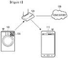
- FIG. 1illustrates a wireless communication system according to a first embodiment of the present disclosure.
- the wireless communication systemmay be configured in the form of a home network, which includes a wireless device 100, a terminal 110, an access point (AP) 120, a home server 130, and may include other similar and/or suitable devices.
- a home networkwhich includes a wireless device 100, a terminal 110, an access point (AP) 120, a home server 130, and may include other similar and/or suitable devices.
- APaccess point
- the wireless device 100may perform Wi-Fi communication, and include a recognition code including device information and the like.
- the recognition codemay be a 2-dimensional (2D) recognition code.
- the recognition code 105may correspond to, for example, a quick response (QR) code 105 and the like, and for convenience of description, the recognition code will be referred to herein as a QR code 105.
- QRquick response
- the QR code 105may include connectivity type information indicating the wireless communication type such as Wi-Fi and the like, information about the operation mode that the terminal 110 should enter in a registration process, a Wi-Fi medium access control (MAC) address, a service set identifier (SSID) and a password, which are used for tethering a connection, uniform resource identifier (URI) information for download of an application, and the like.
- connectivity type informationindicating the wireless communication type such as Wi-Fi and the like, information about the operation mode that the terminal 110 should enter in a registration process, a Wi-Fi medium access control (MAC) address, a service set identifier (SSID) and a password, which are used for tethering a connection, uniform resource identifier (URI) information for download of an application, and the like.
- MACmedium access control
- SSIDservice set identifier
- URIuniform resource identifier
- the terminal 110may obtain information included in the QR code 105 by scanning the QR code 105.
- the terminal 110may enter the tethering mode based on the information obtained from the QR code 105, making it possible to perform a registration procedure for the wireless device 100.
- the AP 120may be connected to the home server 130 and perform communication with the external network. For example, if the terminal 110 transmits URI information, the AP 120 may deliver an application corresponding to the URI to the terminal 110.
- the home server 130may be connected to the external network and the AP 120, and manage information about a variety of devices in the home network.
- FIG. 2to describe a process of registering a wireless device in the wireless communication system illustrated in FIG. 1 .
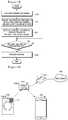
- FIG. 2is a signaling diagram illustrating a process of registering a wireless device in a wireless communication system according to the first embodiment of the present disclosure.
- the terminal 110may obtain information about connectivity type, operation mode, Wi-Fi MAC address, SSID, password, application URI and the like by scanning the QR code 105 included in the wireless device 100.
- the terminal 110may download and install an application using the URI information.
- the applicationmay correspond to an application used for searching for and registering of the wireless device 100, and the terminal 110 may download the application through the AP 120.
- the terminal 110may execute the application and determine the connectivity type and operation mode included in the QR code 105.
- the terminal 110may enter the tethering mode based on the SSID and password, if it is determined that the connectivity type corresponds to Wi-Fi and the operation mode is a station (STA)/AP mode (in which a terminal (or a station) operates as an AP, and a wireless device operates as a terminal for the AP, thereby performing a registration mode).
- the terminal 110may start operating as an AP.
- the wireless device 100may recognize the terminal 110 that operates as an AP.
- the wireless device 100may recognize the terminal 110 as an AP that has the same SSID and password as the SSID and password included in the QR code, through a periodic AP scan process.
- the wireless device 100may recognize the terminal 110 by determining that the terminal 110 is adjacent to the wireless device 100, by means of a proximity sensor or the like.
- the wireless device 100may transmit a connection request message to the terminal 110 in operation 208.
- the wireless device 100may transmit the connection request message immediately after recognizing the terminal 110
- the wireless device 100may transmit the connection request message by receiving a separate input from a user after informing the user of its recognition of the terminal 110 using a display, a voice sign or the like.
- the terminal 110may perform a Wi-Fi connection operation to the wireless device 100 in operation 210.
- the terminal 110may be connected not only to the wireless device 100 but also to a plurality of wireless devices, since the terminal 110 operates as an AP. Therefore, the terminal 110 should detect the wireless device 100 that the terminal 110 desires to register, among the plurality of wireless devices connected to the terminal 110. To this end, in operation 212, the terminal 110 may detect the wireless device 100 among the plurality of wireless devices connected to the terminal 110, based on the Wi-Fi MAC address.
- the terminal 110may broadcast a request signal for discovery of a wireless device to the plurality of wireless devices using a simple service discovery protocol (SSDP)/multicast domain name system (mDNS) or another discovery protocol, and then receive a response signal thereto.
- the terminal 110may detect, as the wireless device 100, the wireless device that has transmitted a response signal including the same Wi-Fi MAC address as the Wi-Fi MAC address that the terminal 110 knows.
- the terminal 110may encrypt AP access information including the information needed for an access to the AP 120, and transmit the encrypted AP access information to the wireless device 100 in operation 214.
- the terminal 110may terminate the tethering mode. Although the terminal 110 may terminate the tethering mode immediately after transmitting the AP access information, the terminal 110 may terminate the tethering mode after receiving a signal indicating the reception of the access information of the AP 120, from the wireless device 100.
- the terminal 110may access again the AP 120 in operation 218.
- the wireless device 100may access the AP 120 based on the AP access information received from the terminal 110.
- the wireless device 100may transmit its own information to the AP 120.
- the AP 120may transmit the information about the wireless device 100 to the home server 130 so that the information about the wireless device 100 may be registered in the home network.
- the terminal 110may detect wireless devices connected to the home network, using the SSDP/mDNS or another discovery protocol. The terminal 110 may allow the user to select at least one of the detected wireless devices by displaying information about the detected wireless devices on the screen. If the user selects the wireless device 100, the terminal 110 may transmit a pairing request to the wireless device 100 and receive a response signal thereto. In operation 222, upon detecting the connection to the wireless device 100, the terminal 110 may perform registration for the wireless device 100.
- FIGS. 3 and 4describe operations of the terminal 110 and the wireless device 100 according to the first embodiment of the present disclosure, respectively.
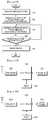
- FIG. 3is a flowchart illustrating an operation of a terminal according to the first embodiment of the present disclosure.
- the terminal 110may obtain device information (e.g., connectivity type, operation mode, Wi-Fi MAC address, SSID, password, application URI and the like) by scanning the QR code 105 of the wireless device 100.
- the terminal 110may download and install an application using the URI
- the terminal 110may execute the application, and if the connectivity type corresponds to Wi-Fi and the operation mode is the STA/AP mode, the terminal 110 may enter the tethering mode using the SSID and password. In operation 306, upon receiving a connection request from the wireless device 100 while the terminal 110 operates as an AP in the tethering mode, the terminal 110 may perform a connection operation to the wireless device 100. In operation 308, the terminal 110 may determine whether the connected wireless device is a relevant wireless device (e.g., the wireless device 100) based on the Wi-Fi MAC address, because the terminal 110 may be connected not only to the wireless device 100 but also to another wireless device.
- a relevant wireless devicee.g., the wireless device 100
- the terminal 110may encrypt AP access information and transmit the encrypted AP access information to the wireless device 100 in operation 312. In operation 314, the terminal 110 may terminate the tethering mode and access the AP 120.
- the terminal 110may detect wireless devices connected to the home network using the SSDP/mDNS or another discovery protocol.
- the terminal 110may allow the user to select at least one of the detected wireless devices by displaying information about the detected wireless devices on the screen.
- the terminal 110may transmit a pairing request to the wireless device 100, and receive a response signal thereto. In operation 316, the terminal 110 may determine its connection to the wireless device 100 and register the wireless device 100.
- FIG. 4is a flowchart illustrating an operation of a wireless device according to the first embodiment of the present disclosure.
- the wireless device 100may detect the terminal 110 operating as an AP, based on the SSID and password included in the QR code 105.
- the wireless device 100may detect the terminal 110 as an AP that has the same SSID and password as the SSID and password included in the QR code 105, through a periodic AP scan process.
- the wireless device 100may detect or discover the terminal 110 by determining whether the specific terminal is the terminal 110 based on the SSID and password included in the QR code 105.
- the wireless device 100may transmit a connection request message to the detected terminal 110 and perform a connection operation.
- the wireless device 100may transmit the Wi-Fi MAC address included in the QR code 105 using a response signal, allowing the terminal 110 to detect the wireless device 100.
- the wireless device 100may access the AP 120 based on the received AP access information in operation 406.
- the wireless device 100may transmit its own information to the AP 120 so that the wireless device 100 may be registered in the home network.
- the wireless device 100may pair with the terminal 110 in operation 408.
- a terminal performing Wi-Fi communicationregisters a wireless device performing Wi-Fi communication by performing P2P communication with the wireless device.
- FIG. 5illustrates a wireless communication system according to a second embodiment of the present disclosure.
- the wireless communication systemmay be configured in the form of a home network, which includes a wireless device 500, a terminal 510, an AP 520, a home server 530, and may include other similar and/or suitable devices.
- the wireless device 500may perform Wi-Fi communication, and include a recognition code including device information and the like.
- the recognition codemay be a 2D recognition code.
- the recognition codemay correspond to, for example, a QR code 505 and the like, and for convenience of description, the recognition code will be referred to herein as a QR code 505.
- the QR code 505may include connectivity type information indicating the wireless communication type such as Wi-Fi and the like, information about the operation mode that the terminal 510 should enter in a registration process, a Wi-Fi MAC address, a P2P personal identification number (PIN) code used to perform P2P communication, URI information for download of an application, and the like.
- the above informationmay be encrypted and then stored in the QR code 505, and the URI information may be recorded in accordance with the QR standard.
- the terminal 510may obtain information included in the QR code 505 by scanning the QR code 505.
- the terminal 510may perform a registration procedure for the wireless device 500 by performing P2P communication with the wireless device 500 based on the information obtained from the QR code 505.
- the AP 520may be connected to the home server 530 and perform communication with the external network. For example, if the terminal 510 transmits URI information, the AP 520 may deliver an application corresponding to the URI to the terminal 510.
- the home server 530may be connected to the external network and the AP 520, and manage information about a variety of devices in the home network.
- FIG. 6to describe a process of registering a wireless device in the wireless communication system illustrated in FIG. 5 .
- FIG. 6is a signaling diagram illustrating a process of registering a wireless device in a wireless communication system according to the second embodiment of the present disclosure.
- the terminal 510may obtain information about connectivity type, operation mode, Wi-Fi MAC address, P2P PIN code, application URI and the like by scanning the QR code 505 included in the wireless device 500.
- the terminal 510may download and install an application using the URI information.
- the applicationmay correspond to an application used for searching for and registering of the wireless device 500, and the terminal 510 may download the application through the AP 520.
- the terminal 510may execute the application and determine the connectivity type and operation mode included in the QR code 505.
- the terminal 510may enter a Wi-Fi P2P mode by turning on a Wi-Fi interface, if it is determined that the connectivity type corresponds to Wi-Fi and the operation mode is the P2P mode (in which a terminal performs a registration procedure by performing P2P communication with a wireless device).
- the terminal 510may detect at least one wireless device for P2P communication, and perform a P2P connection operation based on the P2P PIN code in operation 606.
- the terminal 510may broadcast a request signal for discovery of a wireless device, and then receive a response signal thereto.
- the terminal 510may detect the wireless device that has transmitted the response signal, as a wireless device for P2P communication in operation 608.
- the terminal 510may detect, as a wireless device for P2P communication, the wireless device that has transmitted the same P2P PIN code as the obtained P2P PIN code, among the wireless devices that have transmitted the response signal, and perform a connection operation to the wireless device for P2P communication.
- the P2P PIN codemay be transmitted together with the response signal, or transmitted in a separate signal from the at least one wireless device.
- the terminal 510may determine whether the connected wireless device is the wireless device 500, based on the Wi-Fi MAC address. In other words, the terminal 510 may determine, as the wireless device 500, the wireless device that has the same Wi-Fi MAC address as the Wi-Fi MAC address that the terminal 510 knows.
- the terminal 510may encrypt AP access information for the AP 520 and transmit the encrypted AP access information to the wireless device 500 in operation 610.
- the terminal 510may terminate the Wi-Fi P2P mode and turn off the Wi-Fi interface.
- the terminal 510may terminate the P2P mode after receiving a signal indicating the reception of the AP access information from the wireless device 500.
- the terminal 510may access again the AP 520 in operation 614.
- the wireless device 500may access the AP 520 based on the AP access information received from the terminal 510.
- the wireless device 500may transmit its own information to the AP 520.
- the AP 520may transmit the information about the wireless device 500 to the home server 530 so that the information about the wireless device 500 may be registered in the home network.
- the terminal 510may detect wireless devices connected to the home network, using the SSDP/mDNS or another discovery protocol. The terminal 510 may allow the user to select at least one of the detected wireless devices by displaying information about the detected wireless devices on the screen. If the user selects the wireless device 500, the terminal 510 may transmit a pairing request to the wireless device 500 and receive a response signal thereto. In operation 618, upon detecting the connection to the wireless device 500, the terminal 510 may perform registration for the wireless device 500.
- FIGS. 7 and 8describe operations of the terminal 510 and the wireless device 500 according to the second embodiment of the present disclosure, respectively.
- FIG. 7is a flowchart illustrating an operation of a terminal according to the second embodiment of the present disclosure.
- the terminal 510may obtain device information (e.g., connectivity type, operation mode, Wi-Fi MAC address, P2P PIN code, application URI and the like) by scanning the QR code 505 of the wireless device 500.
- the terminal 510may download and install an application using the URI.
- the terminal 510may execute the application, and enter the Wi-Fi P2P mode and detect a wireless device for P2P communication, if the connectivity type corresponds to Wi-Fi and the operation mode is the P2P mode. In operation 706, the terminal 510 may perform a P2P connection operation to the detected wireless device based on the P2P PIN code.
- the terminal 510may determine whether the detected wireless device is the relevant wireless device 500, based on the Wi-Fi MAC address. If it is determined in operation 710 that the detected wireless device is the relevant wireless device 500, the terminal 510 may encrypt AP access information and transmit the encrypted AP access information to the wireless device 500 in operation 712. In operation 714, the terminal 510 may terminate the Wi-Fi P2P mode and access the AP 520.
- the terminal 510may detect wireless devices connected to the home network, using the SSDP/mDNS or another discovery protocol.
- the terminal 510may allow the user to select at least one of the detected wireless devices by displaying information about the detected wireless devices on the screen.
- the terminal 510may transmit a pairing request to the wireless device 500 and receive a response signal thereto. In operation 716, upon detecting the connection to the wireless device 500, the terminal 510 may perform registration for the wireless device 500.
- FIG. 8is a flowchart illustrating an operation of a wireless device according to the second embodiment of the present disclosure.
- the wireless device 500may perform a P2P connection operation to the terminal 510 based on the P2P PIN code and Wi-Fi MAC address included in the QR code 505.
- the wireless device 500may receive AP access information from the terminal 510 in operation 802, and access the AP 520 based on the received AP access information in operation 804. Thereafter, upon receiving a pairing request by the terminal 510, the wireless device 500 may pair with the terminal 510 in operation 806.
- a terminal performing Wi-Fi communicationregisters a wireless device performing Zigbee communication.
- FIG. 9illustrates a wireless communication system according to a third embodiment of the present disclosure.
- the wireless communication systemmay be configured in the form of a home network, which includes a wireless device 900, a Zigbee IP bridge 910, a terminal 920, an AP 930, a home server 940, and may include other similar and/or suitable devices.
- the wireless device 900may perform Zigbee communication, and include a recognition code including device information and the like.
- the recognition codemay be a 2D recognition code.
- the recognition codemay correspond to, for example, a QR code 905 and the like, and for convenience of description, the recognition code will be referred to herein as a QR code 905.
- the QR code 905may include connectivity type information indicating the wireless communication type such as Zigbee and the like, a Zigbee MAC address, a security key (e.g., an install key and the like; hereinafter the security key will be referred to as an install key), URI information for download of an application, and the like.
- connectivity type informationindicating the wireless communication type such as Zigbee and the like, a Zigbee MAC address, a security key (e.g., an install key and the like; hereinafter the security key will be referred to as an install key), URI information for download of an application, and the like.
- the above informationmay be encrypted and then stored in the QR code 905, and the URI information may be recorded in accordance with the QR standard.
- the terminal 920may obtain information included in the QR code 905 by scanning the QR code 905.
- the terminal 920may perform a registration procedure for the wireless device 900 through the Zigbee IP bridge 910 based on the information obtained from the QR code 905.
- the Zigbee IP bridge 910is a device for connecting the Wi-Fi communication network to the Zigbee communication network.
- the AP 930may be connected to the home server 940 and perform communication with the external network.
- the home server 940may be connected to the external network, and manage information about a variety of devices in the home network.
- FIG. 10is a signaling diagram illustrating a process of registering a wireless device in a wireless communication system according to the third embodiment of the present disclosure.
- the terminal 920may obtain information about connectivity type, Zigbee MAC address, install key, application URI and the like by scanning the QR code 950 included in the wireless device 900.
- the terminal 920may download and install an application using the URI information.
- the applicationmay correspond to an application used for searching for and registering of the wireless device 900, and the terminal 920 may download the application through the AP 930.
- the terminal 920may execute the application and determine the connectivity type included in the QR code 905. In operation 1004, the terminal 920 may search for the Zigbee IP bridge 910 if the connectivity type is determined to be Zigbee. An operation of searching for the Zigbee IP bridge 910 may be performed through a service discovery scheme that uses the SSDP or another discovery protocol.
- the terminal 920may transmit the Zigbee MAC address and the install key to the Zigbee IP bridge 910 in operation 1006.
- the Zigbee IP bridge 910may store information about a wireless device corresponding to the Zigbee MAC address and hash information of the install key. For example, the Zigbee IP bridge 910 may register the hash information in a Zigbee communication modem of the Zigbee IP bridge 910.
- the wireless device 900may transmit a registration request message including information about the wireless device 900 to the Zigbee IP bridge 910 in operation 1012.
- the Zigbee IP bridge 910may approve registration for the terminal 920 based on the stored information and transmit a registration approval message to the wireless device 900.
- the wireless device 900may recognize the terminal 920 using short-range wireless communication such as a proximity sensor, near field communication (NFC) and the like.
- the Zigbee IP bridge 910may transmit the pairing completion results indicating its connection to the wireless device 900, to the terminal 920 via the Wi-Fi interface.
- the Zigbee IP bridge 910may transmit the registration completion results including information about the wireless device 900 to the home server 940 in order to register the wireless device 900 in the home network.
- FIGS. 11 to 13describe operations of the terminal 920, the Zigbee IP bridge 910 and the wireless device 900 according to the third embodiment of the present disclosure, respectively.
- FIG. 11is a flowchart illustrating an operation of a terminal according to the third embodiment of the present disclosure.
- the terminal 920may obtain device information (e.g., connectivity type, Zigbee MAC address, install key, and application URI) by scanning the QR code 905.
- the terminal 920may download and install an application using the URI.
- the terminal 920may execute the application, and search for the Zigbee IP bridge 910 if the connectivity type corresponds to Zigbee. Upon detecting the Zigbee IP bridge 910, the terminal 920 may transmit the Zigbee MAC address and install key information to the detected Zigbee IP bridge 910 in operation 1106.
- the terminal 920may register the wireless device 900 and terminate the registration procedure.
- FIG. 12is a flowchart illustrating an operation of a Zigbee IP bridge according to the third embodiment of the present disclosure.
- the Zigbee IP bridge 910may receive a Zigbee MAC address and an install key from the terminal 920. In operation 1202, the Zigbee IP bridge 910 may store hash information of the install key together with the information about a wireless device corresponding to the Zigbee MAC address.
- the Zigbee IP bridge 910may determine whether a registration request is received from the wireless device 900. Upon receiving the registration request in operation 1206, the Zigbee IP bridge 910 may determine whether to approve registration of the wireless device 900 based on the stored information, in operation 1208.
- the Zigbee IP bridge 910may transmit a registration approval message to the wireless device 900 in operation 1212. In operation 1214, the Zigbee IP bridge 910 may transmit the pairing completion results to the terminal 920, or transmit the registration completion results to the home server 940.
- FIG. 13is a flowchart illustrating an operation of a wireless device according to the third embodiment of the present disclosure.
- the wireless device 900may transmit a registration request message to the Zigbee IP bridge 910 using a Zigbee MAC address and an install key included in the QR code 905 in operation 1302. In operation 1304, the wireless device 900 may determine whether a registration approval message is received from the Zigbee IP bridge 910. Upon receiving the registration approval message in operation 1306, the wireless device 900 may perform pairing with the terminal 920 in operation 1308.
- a terminal performing Wi-Fi communicationregisters a wireless device performing Z-wave communication.
- FIG. 14illustrates a wireless communication system according to a fourth embodiment of the present disclosure.
- the wireless communication systemmay be configured in the form of a home network, which includes a wireless device 1400, a Z-wave IP bridge 1410, a terminal 1420, an AP 1430, a home server 1440, and may include other similar and/or suitable devices.
- the wireless device 1400may perform Z-wave communication, and include a recognition code including device information and the like.
- the recognition codemay be a 2D recognition code.
- the recognition codemay correspond to, for example, a QR code 1405 and the like, and for convenience of description, the recognition code will be referred to herein as a QR code 1405.
- the QR code 1405may include connectivity type information indicating the wireless communication type such as Z-wave and the like, a Z-wave Secure Remote Password (SRP), URI information for download of an application, and the like.
- the above informationmay be encrypted and then stored in the QR code 1405, and the URI information may be recorded in accordance with the QR standard.
- the terminal 1420may obtain information included in the QR code 1405 by scanning the QR code 1405.
- the terminal 1420may perform a registration procedure for the wireless device 1400 through the Z-wave IP bridge 1410 based on the information obtained from the QR code 1405.
- the Z-wave IP bridge 1410is a device for connecting the Wi-Fi communication network to the Z-wave communication network.
- the AP 1430may be connected to the home server 1440 and perform communication with the external network.
- the home server 1440may be connected to the external network, and manage information about a variety of devices in the home network.
- FIG. 15is a signaling diagram illustrating a process of registering a wireless device in a wireless communication system according to the fourth embodiment of the present disclosure.
- the terminal 1420may obtain information about connectivity type, Z-wave SRP, application URI and the like by scanning the QR code 1450 included in the wireless device 1400.
- the terminal 1420may download and install an application using the URI information.
- the applicationmay correspond to an application used for searching for and registering of the wireless device 1400, and the terminal 1420 may download the application through the AP 1430.
- the terminal 1420may execute the application.
- the terminal 1420may search for the Z-wave IP bridge 1410 if the connectivity type included in the QR code 1405 corresponds to Z-wave.
- An operation of searching for the Z-wave IP bridge 1410may be performed through a service discovery scheme that uses the SSDP or another discovery protocol.
- the terminal 1420may transmit the Z-wave SRP to the Z-wave IP bridge 1410 in operation 1506.
- the Z-wave IP bridge 1410may store the Z-wave SRP.
- the wireless device 1400may transmit a registration request to the Z-wave IP bridge 1410 in operation 1512.
- the Z-wave IP bridge 1410may approve registration for the terminal 1420 based on the stored Z-wave SRP information.
- the wireless device 1400may recognize the terminal 1420 using short-range wireless communication such as a proximity sensor, NFC and the like.
- the Z-wave IP bridge 1410may transmit the pairing completion results indicating its connection to the wireless device 1400, to the terminal 1420 via the Wi-Fi interface.
- the Z-wave IP bridge 1410may transmit the registration completion results including information about the wireless device 1400 to the home server 1440 in order to register the wireless device 1400 in the home network.
- FIGS. 16 to 18describe operations of the terminal 1420, the Z-wave IP bridge 1410 and the wireless device 1400 according to the fourth embodiment of the present disclosure, respectively.
- FIG. 16is a flowchart illustrating an operation of a terminal according to the fourth embodiment of the present disclosure.
- the terminal 1420may obtain device information (e.g., connectivity type, Z-wave SRP, and application URI) by scanning the QR code 1405.
- the terminal 1420may download and install an application using the URI
- the terminal 1420may execute the application and search for the Z-wave IP bridge 1410 if the connectivity type corresponds to Z-wave. Upon detecting the Z-wave IP bridge 1410, the terminal 1420 may transmit the Z-wave SRP to the detected Z-wave IP bridge 1410 in operation 1606.
- the terminal 1420may register the wireless device 1400 and terminate the registration procedure.
- FIG. 17is a flowchart illustrating an operation of a Z-wave IP bridge according to the fourth embodiment of the present disclosure.
- the Z-wave IP bridge 1410may receive a Z-wave SRP from the terminal 1420 and store the Z-wave SRP in operation 1700.
- the Z-wave IP bridge 1410may determine in operation 1702 whether a registration request is received from the wireless device 1400. Upon receiving the registration request in operation 1704, the Z-wave IP bridge 1410 may determine in operation 1706 whether to approve registration of the wireless device 1400 based on the stored Z-wave SRP information.
- the Z-wave IP bridge 1410may transmit a registration approval message to the wireless device 1400 in operation 1710. In operation 1712, the Z-wave IP bridge 1410 may transmit the pairing completion results to the terminal 1420, or transmit the registration completion results to the home server 1440.
- FIG. 18is a flowchart illustrating an operation of a wireless device according to the fourth embodiment of the present disclosure.
- the wireless device 1400may transmit a registration request message to the Z-wave IP bridge 1410 using a Z-wave SRP included in the QR code 1405 in operation 1802.
- the wireless device 1400may determine in operation 1804 whether a registration approval message is received from the Z-wave IP bridge 1410.
- the wireless device 1400may perform pairing with the terminal 1420 in operation 1808.
- FIG. 19is a block diagram of a wireless device according to an embodiment of the present disclosure.
- the wireless devicemay include a wireless unit 1900, a memory 1902, a sensor unit 1904, a controller 1906, and may include other similar and/or suitable devices.
- the wireless unit 1900is a component for wireless communication of the wireless device.
- the wireless unit 1900may include at least one of a Wi-Fi interface for Wi-Fi communication, a Zigbee interface for Zigbee communication, and a Z-wave interface for Z-wave communication.
- the memory 1902may store a variety of information and data that are generated during an operation of the wireless device.
- the sensor unit 1904may determine whether a specific device such as a terminal and the like is adjacent to the wireless device, and output the determination results.
- the sensor unit 1904may be configured in various types such as an infrared sensor, a motion sensor and the like.
- the controller 1906may control the overall operation of the wireless device by controlling the wireless unit 1900, the memory 1902 and the sensor unit 1904.
- the controller 1906may control the above components such that the operation of the wireless device may be performed according to the first to fourth embodiments of the present disclosure.
- FIG. 20is a block diagram of a terminal according to an embodiment of the present disclosure.
- the terminalmay include a wireless unit 2000, a memory 2002, a QR code scanner 2004, a controller 2006, and may include other similar and/or suitable devices.
- the wireless unit 1900is a component for wireless communication of the terminal.
- the wireless unit 2000may include a Wi-Fi interface for Wi-Fi communication, and an interface for Long Term Evolution (LTE) communication.
- LTELong Term Evolution
- the memory 2002may store a variety of information and data that are generated during an operation of the terminal.
- the memory 2002may store the information included in the QR code that is scanned from the wireless device.
- the QR code scanner 2004,which is a component for scanning a QR code included in the wireless device, may include, for example, a camera and the like.
- the controller 2006may control the overall operation of the terminal by controlling the wireless unit 2000, the memory 2002 and the QR code scanner 2004.
- the controller 2006may control the above components such that the operation of the terminal may be performed according to the first to fourth embodiments of the present disclosure.
- the method and apparatus according to embodiments of the present disclosuremay be implemented in the form of hardware, software or a combination thereof.
- the softwaremay be stored in a volatile or nonvolatile storage device (e.g., an erasable/re-writable read-only memory (ROM) or the like), a memory (e.g., a random access memory (RAM), a memory chip, a memory integrated circuit (IC) or the like), or an optically or magnetically recordable machine (e.g., computer)-readable storage medium (e.g., compact disk (CD), digital versatile disk (DVD), magnetic disk, magnetic tape or the like).
- a volatile or nonvolatile storage devicee.g., an erasable/re-writable read-only memory (ROM) or the like
- a memorye.g., a random access memory (RAM), a memory chip, a memory integrated circuit (IC) or the like
- an optically or magnetically recordable machinee.g., computer-readable storage
- the method according to embodiments of the present disclosuremay be implemented by a computer or a portable terminal, which includes a controller and a memory.
- the memoryis an example of the machine-readable storage medium suitable to store a program or programs including instructions for implementing embodiments of the present disclosure.
- the present disclosuremay include a program including codes for implementing the method and apparatus as defined by the appended claims, and also include a non-transitory machine (e.g., computer or the like)-readable storage medium storing the program.
- the programmay be electronically carried on any media such as communication signals that are transmitted through wired/wireless connections.
- the informatione.g., Wi-Fi MAC address, and SSID and password for tethering connection in the case of Wi-Fi; Zigbee MAC address and install key in the case of Zigbee; and SRP key and URI for download of an application in the case of Z-wave
- the QR codemounted on a wireless device, thereby to omit the input procedure which was conventionally performed by the user, making it possible to perform the fast and easy device registration procedure.
- a security schemesuch as an elliptic curve cryptography (ECC) scheme or the like
- ECCelliptic curve cryptography
- the security key included in the QR codemay be transmitted to the Zigbee bridge that is connected to the Zigbee wireless device, so the security key input procedure may be omitted.
- the device registration proceduremay be automatically performed, so the user may conveniently pair the relevant devices.
- each wireless devicemay be directly connected to the terminal since an individual SSID is used for each wireless device, making it possible to prevent other wireless devices except for the wireless device from being registered.
- the usermay perform pairing between wireless devices though intuitive user experience (UX).
- UXintuitive user experience
- the waiting timemay increase in the registration procedure, and the SSID may be exposed to other users due to the use of the fixed SSID.
- the exposuremay be prevented, improving the security, and the registration time may be reduced and the registration procedure may be simplified.
Landscapes
- Engineering & Computer Science (AREA)
- Computer Networks & Wireless Communication (AREA)
- Signal Processing (AREA)
- Databases & Information Systems (AREA)
- Computer Security & Cryptography (AREA)
- Computer Vision & Pattern Recognition (AREA)
- Physics & Mathematics (AREA)
- General Physics & Mathematics (AREA)
- Multimedia (AREA)
- Theoretical Computer Science (AREA)
- Mobile Radio Communication Systems (AREA)
Description
- The present disclosure relates to a method and apparatus for registering a wireless device in a wireless communication system.
- In recent years, due to the increase in use of wireless communication, there is an increasing demand for connecting new wireless communication devices to the communication network. In addition, there is a need for temporary connection between wireless devices based on wireless communication technology, and in this case, pairing should be performed between the wireless devices.
- In a related-art wireless communication system, the pairing may be performed by an application installation process and a device registration/authentication process according to the related art. The application installation process represents a process in which a user searches for and downloads an application for pairing, which is deployed by an operator, or downloads and installs a pairing application, which is provided from a separate provider.
- The device registration/authentication process may include a process of recognizing a wireless device for pairing, with minimized power, registering the wireless device by receiving a personal identification number (PIN) code, blocking the registration of other wireless devices during pairing, and performing encrypted communication through the exchange of authentication keys. The device registration/authentication process will be described in detail below.
- A wireless device used for registering devices (hereinafter referred to as a 'device registration-purpose wireless device') may perform registration for adjacent wireless devices in order to minimize transmit power. Therefore, the device registration-purpose wireless device should move to the place adjacent to the wireless device that the device registration-purpose wireless device will register, or a wireless device subject to the registration procedure should move to the place adjacent to the device registration-purpose wireless device. In this way, for pairing between two wireless devices, the two wireless devices should be placed adjacent to each other by the user. Therefore, the existing device registration method may be limited to the user-dependent method because the user's active involvement is required.
- If the two wireless devices exist in the adjacent places, a communication environment for communication between the two wireless devices may be provided, and a PIN code may be used for encrypted communication. The device registration-purpose wireless device may provide a PIN code that is randomly generated, or provided from an associated system, to a relevant wireless device, and determine the wireless device to which a PIN code corresponding to the provided PIN code is applied, as a wireless device that the device registration-purpose wireless device will register, thereby performing the registration procedure.
- When performing the registration procedure, the device registration-purpose wireless device may block any devices from involvement in the registration during the registration procedure by ignoring all the other adjacent devices for a period of a preset time.
- For security, two wireless devices, which are not open before pairing, may exchange keys needed for authentication using separate wired communication (e.g., universal asynchronous receiver/transmitter (UART) communication or the like) and closed wireless communication (e.g., infrared data association (IrDA) communication or the like), and then, perform a registration procedure through an authentication process. The two wireless devices may perform the registration procedure through encrypted security communication, using Peer-to-Peer (P2P) communication of near field communication (NFC).
- The above information is presented as background information only to assist with an understanding of the present disclosure. No determination has been made, and no assertion is made, as to whether any of the above might be applicable as prior art with regard to the present disclosure.
US 2005/0139680 A1 discloses systems, methods and applications for establishing a short-range communication link between digital devices for the purpose of transferring data between the devices.US 2011/289229 A1 relates to the configuration of electronic devices to connect to wireless networks, especially when those electronic devices have limited user interfaces and/or no display screen.- In this pairing scheme, even though pairing is normally performed, another wireless device adjacent to the device registration-purpose wireless device is likely to be registered, instead of the wireless device that the user desires to register. In addition, the pairing scheme may undergo complicated pairing settings, because application installation and device registration should be separately performed, instead of being performed as one process, and identifiers (IDs) and passwords for multiple items are required.
- Aspects of the present disclosure are to address at least the above-mentioned problems and/or disadvantages and to provide at least the advantages described below. Accordingly, an aspect of the present disclosure is to provide a method and apparatus for registering a wireless device in a wireless communication system.
- Another aspect of the present disclosure is to provide a wireless device registration method and apparatus for reducing a registration time and simplifying a registration procedure for a wireless device.
- Another aspect of the present disclosure is to provide a method and apparatus for allowing a desired wireless device to be securely registered without involvement of another wireless device.
- In accordance with an aspect of the present disclosure, a method by a first electronic device for facilitating a connection of a second electronic device to an access point in a wireless communication system is provided. The method comprises obtaining a quick response, QR, code on the second electronic device, the QR code being obtained by using a camera of the first electronic device and identifying connection information for establishing a connection with the second electronic device based on the obtained QR code, the connection information including identification information of the second electronic device. The method further comprises establishing the connection with the second electronic device based on the identified connection information and transmitting access information of the access point to the second electronic device over the established connection with the second electronic device. The access information of the access point is used for the second electronic device to connect to the access point. The method further comprises detecting that the second electronic device is connected to the access point and registering the second electronic device, in the wireless communication system, based at least on detecting that the second electronic device is connected to the access point.
- In accordance with an aspect of the present disclosure, a system comprising a first electronic device configured to perform one of the above method and a second electronic device is provided. The second electronic device is configured to receive the access information of the access point from the first electronic device and to establish a connection with the access point based on the received access information of the access point.
- In accordance with an aspect of the present disclosure, which is not part of the present invention, a method for registering a wireless device by a terminal in a wireless communication system is provided. The method includes obtaining connection information for the wireless device by scanning a recognition code of the wireless device in a first mode, transitioning to a second mode based on the connection information and receiving a connection request from the wireless device, performing a connection operation to the wireless device to transmit network access information to the wireless device, and transitioning to the first mode, and registering the wireless device upon detecting connection of the wireless device to a network in the first mode.
- In accordance with another aspect of the present disclosure, which is not part of the present invention, a method for registering a wireless device by a terminal in a wireless communication system is provided. The method includes obtaining connection information for the wireless device by scanning a recognition code of the wireless device, detecting an intermediate node connecting with a communication network between the terminal and the wireless device, based on the connection information, transmitting information for connection to the wireless device to the intermediate node, the information being included in the connection information, and registering the wireless device upon receiving information indicating connection to the wireless device, from the intermediate node.
- In accordance with further another aspect of the present disclosure, which is not part of the present invention, a terminal for registering a wireless device in a wireless communication system is provided. The terminal includes a wireless unit, a recognition code scanner configured to obtain connection information for the wireless device by scanning a recognition code of the wireless device in a first mode, and a controller configured to transition to a second mode based on the connection information, to control the wireless unit to receive a connection request from the wireless device, to perform a connection operation to the wireless device to transmit network access information to the wireless device, to transition to the first mode, and to register the wireless device upon detecting connection of the wireless device to a network in the first mode.
- In accordance with yet another aspect of the present disclosure, which is not part of the present invention, a terminal for registering a wireless device in a wireless communication system is provided. The terminal includes a wireless unit, a recognition code scanner configured to obtain connection information for the wireless device by scanning a recognition code of the wireless device, and a controller configured to detect an intermediate node connecting with a communication network between the terminal and the wireless device, based on the connection information, to control the wireless unit to transmit information for connection to the wireless device to the intermediate node, the information being included in the connection information, and to register the wireless device upon receiving information indicating connection to the wireless device, from the intermediate node.
- Other aspects, advantages, and salient features of the disclosure will become apparent to those skilled in the art from the following detailed description, which, taken in conjunction with the annexed drawings, discloses various embodiments of the present disclosure.
- The above and other aspects, features, and advantages of certain y embodiments of the present disclosure will be more apparent from the following description taken in conjunction with the accompanying drawings, in which:
FIG. 1 illustrates a wireless communication system according to a first embodiment of the present disclosure;FIG. 2 is a signaling diagram illustrating a process of registering a wireless device in a wireless communication system according to the first embodiment of the present disclosure;FIG. 3 is a flowchart illustrating an operation of a terminal according to the first embodiment of the present disclosure;FIG. 4 is a flowchart illustrating an operation of a wireless device according to the first embodiment of the present disclosure;FIG. 5 illustrates a wireless communication system according to a second embodiment of the present disclosure;FIG. 6 is a signaling diagram illustrating a process of registering a wireless device in a wireless communication system according to the second embodiment of the present disclosure;FIG. 7 is a flowchart illustrating an operation of a terminal according to the second embodiment of the present disclosure;FIG. 8 is a flowchart illustrating an operation of a wireless device according to the second embodiment of the present disclosure;FIG. 9 illustrates a wireless communication system according to a third embodiment of the present disclosure;FIG. 10 is a signaling diagram illustrating a process of registering a wireless device in a wireless communication system according to the third embodiment of the present disclosure;FIG. 11 is a flowchart illustrating an operation of a terminal according to the third embodiment of the present disclosure;FIG. 12 is a flowchart illustrating an operation of a Zigbee internet protocol (IP) bridge according to the third embodiment of the present disclosure;FIG. 13 is a flowchart illustrating an operation of a wireless device according to the third embodiment of the present disclosure;FIG. 14 illustrates a wireless communication system according to a fourth embodiment of the present disclosure;FIG. 15 is a signaling diagram illustrating a process of registering a wireless device in a wireless communication system according to the fourth embodiment of the present disclosure;FIG. 16 is a flowchart illustrating an operation of a terminal according to the fourth embodiment of the present disclosure;FIG. 17 is a flowchart illustrating an operation of a Z-wave IP bridge according to the fourth embodiment of the present disclosure;FIG. 18 is a flowchart illustrating an operation of a wireless device according to the fourth embodiment of the present disclosure;FIG. 19 is a block diagram of a wireless device according to an embodiment of the present disclosure; andFIG. 20 is a block diagram of a terminal according to an embodiment of the present disclosure.- Throughout the drawings, like reference numerals will be understood to refer to like parts, components, and structures.
- The following description with reference to the accompanying drawings is provided to assist in a comprehensive understanding of various embodiments of the present disclosure as defined by the claims. It includes various specific details to assist in that understanding but these are to be regarded as merely exemplary. Accordingly, those of ordinary skilled in the art will recognize that various changes and modifications of the various embodiments described herein can be made. In addition, descriptions of well-known functions and constructions may be omitted for clarity and conciseness.
- The terms and words used in the following description are not limited to the bibliographical meanings, but, are merely used by the inventor to enable a clear and consistent understanding of the present disclosure. Accordingly, it should be apparent to those skilled in the art that the following description of various embodiments of the present disclosure is provided for illustration purpose only and not for the purpose of limiting the present disclosure as defined by the appended claims.
- It is to be understood that the singular forms "a," "an," and "the" include plural referents unless the context clearly dictates otherwise. Thus, for example, reference to "a component surface" includes reference to one or more of such surfaces..
- An aspect of the present disclosure provides a method and apparatus for registering a wireless device in a wireless communication system. The present disclosure provides the following four possible embodiments depending on the type of the wireless communication used by a wireless device and a terminal. In a first embodiment of the present disclosure, a terminal performing wireless fidelity (Wi-Fi) communication may register a wireless device performing Wi-Fi communication based on a tethering mode. In a second embodiment of the present disclosure, a terminal performing Wi-Fi communication may register a wireless device performing Wi-Fi communication by performing peer-to-peer (P2P) communication with the wireless device. In a third embodiment of the present disclosure, a terminal performing Wi-Fi communication may register a wireless device performing Zigbee communication. In a fourth embodiment of the present disclosure, a terminal performing Wi-Fi communication may register a wireless device performing Z-wave communication.
- The wireless device proposed in the first to fourth embodiments of the present disclosure may include home appliances capable of wireless communication, such as washing machines, refrigerators, televisions and the like. The terminal proposed in the first to fourth embodiments of the present disclosure may include cellular phones, tablet personal computers (PCs) and the like, all of which are capable of wireless communication. However, the wireless device and the terminal may not be limited to the above devices, and may include any other devices.
- Each of the four embodiments of the present disclosure will now be detailed in detail.
FIG. 1 illustrates a wireless communication system according to a first embodiment of the present disclosure.- Referring to
FIG. 1 , the wireless communication system according to the first embodiment of the present disclosure may be configured in the form of a home network, which includes awireless device 100, a terminal 110, an access point (AP) 120, ahome server 130, and may include other similar and/or suitable devices. - The
wireless device 100 may perform Wi-Fi communication, and include a recognition code including device information and the like. The recognition code may be a 2-dimensional (2D) recognition code. Therecognition code 105 may correspond to, for example, a quick response (QR)code 105 and the like, and for convenience of description, the recognition code will be referred to herein as aQR code 105. - In the first embodiment of the present disclosure, the
QR code 105 may include connectivity type information indicating the wireless communication type such as Wi-Fi and the like, information about the operation mode that the terminal 110 should enter in a registration process, a Wi-Fi medium access control (MAC) address, a service set identifier (SSID) and a password, which are used for tethering a connection, uniform resource identifier (URI) information for download of an application, and the like. The above information may be encrypted and then stored in theQR code 105, and the URI information may be recorded in accordance with the QR standard. - The terminal 110, a device capable of performing Wi-Fi communication, may obtain information included in the
QR code 105 by scanning theQR code 105. The terminal 110 may enter the tethering mode based on the information obtained from theQR code 105, making it possible to perform a registration procedure for thewireless device 100. - The
AP 120 may be connected to thehome server 130 and perform communication with the external network. For example, if the terminal 110 transmits URI information, theAP 120 may deliver an application corresponding to the URI to the terminal 110. - The
home server 130 may be connected to the external network and theAP 120, and manage information about a variety of devices in the home network. - Reference will now be made to
FIG. 2 , to describe a process of registering a wireless device in the wireless communication system illustrated inFIG. 1 . FIG. 2 is a signaling diagram illustrating a process of registering a wireless device in a wireless communication system according to the first embodiment of the present disclosure.- Referring to
FIG. 2 , inoperation 200, the terminal 110 may obtain information about connectivity type, operation mode, Wi-Fi MAC address, SSID, password, application URI and the like by scanning theQR code 105 included in thewireless device 100. Inoperation 202, the terminal 110 may download and install an application using the URI information. The application may correspond to an application used for searching for and registering of thewireless device 100, and the terminal 110 may download the application through theAP 120. - The terminal 110 may execute the application and determine the connectivity type and operation mode included in the
QR code 105. Inoperation 204, the terminal 110 may enter the tethering mode based on the SSID and password, if it is determined that the connectivity type corresponds to Wi-Fi and the operation mode is a station (STA)/AP mode (in which a terminal (or a station) operates as an AP, and a wireless device operates as a terminal for the AP, thereby performing a registration mode). The terminal 110 may start operating as an AP. - In
operation 206, thewireless device 100 may recognize the terminal 110 that operates as an AP. For example, thewireless device 100 may recognize the terminal 110 as an AP that has the same SSID and password as the SSID and password included in the QR code, through a periodic AP scan process. Thewireless device 100 may recognize the terminal 110 by determining that the terminal 110 is adjacent to thewireless device 100, by means of a proximity sensor or the like. - Upon recognizing the terminal 110, the
wireless device 100 may transmit a connection request message to the terminal 110 inoperation 208. Herein, although thewireless device 100 may transmit the connection request message immediately after recognizing the terminal 110, thewireless device 100 may transmit the connection request message by receiving a separate input from a user after informing the user of its recognition of the terminal 110 using a display, a voice sign or the like. - Upon receiving the connection request message, the terminal 110 may perform a Wi-Fi connection operation to the
wireless device 100 inoperation 210. The terminal 110 may be connected not only to thewireless device 100 but also to a plurality of wireless devices, since the terminal 110 operates as an AP. Therefore, the terminal 110 should detect thewireless device 100 that the terminal 110 desires to register, among the plurality of wireless devices connected to the terminal 110. To this end, inoperation 212, the terminal 110 may detect thewireless device 100 among the plurality of wireless devices connected to the terminal 110, based on the Wi-Fi MAC address. - For example, the terminal 110 may broadcast a request signal for discovery of a wireless device to the plurality of wireless devices using a simple service discovery protocol (SSDP)/multicast domain name system (mDNS) or another discovery protocol, and then receive a response signal thereto. The terminal 110 may detect, as the
wireless device 100, the wireless device that has transmitted a response signal including the same Wi-Fi MAC address as the Wi-Fi MAC address that the terminal 110 knows. - Upon detecting the
wireless device 100, the terminal 110 may encrypt AP access information including the information needed for an access to theAP 120, and transmit the encrypted AP access information to thewireless device 100 inoperation 214. Inoperation 216, the terminal 110 may terminate the tethering mode. Although the terminal 110 may terminate the tethering mode immediately after transmitting the AP access information, the terminal 110 may terminate the tethering mode after receiving a signal indicating the reception of the access information of theAP 120, from thewireless device 100. - After terminating the tethering mode, the terminal 110 may access again the
AP 120 inoperation 218. Inoperation 220, thewireless device 100 may access theAP 120 based on the AP access information received from the terminal 110. Thewireless device 100 may transmit its own information to theAP 120. Then, theAP 120 may transmit the information about thewireless device 100 to thehome server 130 so that the information about thewireless device 100 may be registered in the home network. - The terminal 110 may detect wireless devices connected to the home network, using the SSDP/mDNS or another discovery protocol. The terminal 110 may allow the user to select at least one of the detected wireless devices by displaying information about the detected wireless devices on the screen. If the user selects the
wireless device 100, the terminal 110 may transmit a pairing request to thewireless device 100 and receive a response signal thereto. Inoperation 222, upon detecting the connection to thewireless device 100, the terminal 110 may perform registration for thewireless device 100. - Next, reference will be made to
FIGS. 3 and4 , to describe operations of the terminal 110 and thewireless device 100 according to the first embodiment of the present disclosure, respectively. FIG. 3 is a flowchart illustrating an operation of a terminal according to the first embodiment of the present disclosure.- Referring to
FIG. 3 , inoperation 300, the terminal 110 may obtain device information (e.g., connectivity type, operation mode, Wi-Fi MAC address, SSID, password, application URI and the like) by scanning theQR code 105 of thewireless device 100. Inoperation 302, the terminal 110 may download and install an application using the URI - In
operation 304, the terminal 110 may execute the application, and if the connectivity type corresponds to Wi-Fi and the operation mode is the STA/AP mode, the terminal 110 may enter the tethering mode using the SSID and password. Inoperation 306, upon receiving a connection request from thewireless device 100 while the terminal 110 operates as an AP in the tethering mode, the terminal 110 may perform a connection operation to thewireless device 100. Inoperation 308, the terminal 110 may determine whether the connected wireless device is a relevant wireless device (e.g., the wireless device 100) based on the Wi-Fi MAC address, because the terminal 110 may be connected not only to thewireless device 100 but also to another wireless device. - If it is determined in
operation 310 that theconnected wireless device 100 is the relevant wireless device, the terminal 110 may encrypt AP access information and transmit the encrypted AP access information to thewireless device 100 inoperation 312. Inoperation 314, the terminal 110 may terminate the tethering mode and access theAP 120. - The terminal 110 may detect wireless devices connected to the home network using the SSDP/mDNS or another discovery protocol. The terminal 110 may allow the user to select at least one of the detected wireless devices by displaying information about the detected wireless devices on the screen.
- If the user selects the
wireless device 100, the terminal 110 may transmit a pairing request to thewireless device 100, and receive a response signal thereto. Inoperation 316, the terminal 110 may determine its connection to thewireless device 100 and register thewireless device 100. FIG. 4 is a flowchart illustrating an operation of a wireless device according to the first embodiment of the present disclosure.- Referring to
FIG. 4 , inoperation 400, thewireless device 100 may detect the terminal 110 operating as an AP, based on the SSID and password included in theQR code 105. Thewireless device 100 may detect the terminal 110 as an AP that has the same SSID and password as the SSID and password included in theQR code 105, through a periodic AP scan process. After determining that a specific terminal is adjacent to thewireless device 100 by means of a proximity sensor or the like, thewireless device 100 may detect or discover the terminal 110 by determining whether the specific terminal is the terminal 110 based on the SSID and password included in theQR code 105. - In
operation 402, thewireless device 100 may transmit a connection request message to the detectedterminal 110 and perform a connection operation. Upon receiving a request signal for discovery from the terminal 110, thewireless device 100 may transmit the Wi-Fi MAC address included in theQR code 105 using a response signal, allowing the terminal 110 to detect thewireless device 100. - After performing the above process, upon receiving AP access information from the terminal 110 in
operation 404, thewireless device 100 may access theAP 120 based on the received AP access information inoperation 406. Thewireless device 100 may transmit its own information to theAP 120 so that thewireless device 100 may be registered in the home network. Upon receiving a pairing request by the terminal 110, thewireless device 100 may pair with the terminal 110 inoperation 408. - Next, a description will be made of the second embodiment of the present disclosure, in which a terminal performing Wi-Fi communication registers a wireless device performing Wi-Fi communication by performing P2P communication with the wireless device.
FIG. 5 illustrates a wireless communication system according to a second embodiment of the present disclosure.- Referring to
FIG. 5 , the wireless communication system according to the second embodiment of the present disclosure may be configured in the form of a home network, which includes awireless device 500, a terminal 510, anAP 520, ahome server 530, and may include other similar and/or suitable devices. - The
wireless device 500 may perform Wi-Fi communication, and include a recognition code including device information and the like. The recognition code may be a 2D recognition code. The recognition code may correspond to, for example, aQR code 505 and the like, and for convenience of description, the recognition code will be referred to herein as aQR code 505. - In the second embodiment of the present disclosure, the
QR code 505 may include connectivity type information indicating the wireless communication type such as Wi-Fi and the like, information about the operation mode that the terminal 510 should enter in a registration process, a Wi-Fi MAC address, a P2P personal identification number (PIN) code used to perform P2P communication, URI information for download of an application, and the like. The above information may be encrypted and then stored in theQR code 505, and the URI information may be recorded in accordance with the QR standard. - The terminal 510, a device capable of performing Wi-Fi communication, may obtain information included in the
QR code 505 by scanning theQR code 505. The terminal 510 may perform a registration procedure for thewireless device 500 by performing P2P communication with thewireless device 500 based on the information obtained from theQR code 505. - The
AP 520 may be connected to thehome server 530 and perform communication with the external network. For example, if the terminal 510 transmits URI information, theAP 520 may deliver an application corresponding to the URI to the terminal 510. - The
home server 530 may be connected to the external network and theAP 520, and manage information about a variety of devices in the home network. - Reference will now be made to
FIG. 6 , to describe a process of registering a wireless device in the wireless communication system illustrated inFIG. 5 . FIG. 6 is a signaling diagram illustrating a process of registering a wireless device in a wireless communication system according to the second embodiment of the present disclosure.- Referring to
FIG. 6 , inoperation 600, the terminal 510 may obtain information about connectivity type, operation mode, Wi-Fi MAC address, P2P PIN code, application URI and the like by scanning theQR code 505 included in thewireless device 500. Inoperation 602, the terminal 510 may download and install an application using the URI information. The application may correspond to an application used for searching for and registering of thewireless device 500, and the terminal 510 may download the application through theAP 520. - The terminal 510 may execute the application and determine the connectivity type and operation mode included in the
QR code 505. Inoperation 604, the terminal 510 may enter a Wi-Fi P2P mode by turning on a Wi-Fi interface, if it is determined that the connectivity type corresponds to Wi-Fi and the operation mode is the P2P mode (in which a terminal performs a registration procedure by performing P2P communication with a wireless device). The terminal 510 may detect at least one wireless device for P2P communication, and perform a P2P connection operation based on the P2P PIN code inoperation 606. - Specifically, the terminal 510 may broadcast a request signal for discovery of a wireless device, and then receive a response signal thereto. The terminal 510 may detect the wireless device that has transmitted the response signal, as a wireless device for P2P communication in
operation 608. The terminal 510 may detect, as a wireless device for P2P communication, the wireless device that has transmitted the same P2P PIN code as the obtained P2P PIN code, among the wireless devices that have transmitted the response signal, and perform a connection operation to the wireless device for P2P communication. The P2P PIN code may be transmitted together with the response signal, or transmitted in a separate signal from the at least one wireless device. Here, the terminal 510 may determine whether the connected wireless device is thewireless device 500, based on the Wi-Fi MAC address. In other words, the terminal 510 may determine, as thewireless device 500, the wireless device that has the same Wi-Fi MAC address as the Wi-Fi MAC address that the terminal 510 knows. - If the connected wireless device is determined to be the
wireless device 500, the terminal 510 may encrypt AP access information for theAP 520 and transmit the encrypted AP access information to thewireless device 500 inoperation 610. Inoperation 612, the terminal 510 may terminate the Wi-Fi P2P mode and turn off the Wi-Fi interface. Although not illustrated inFIG. 6 , the terminal 510 may terminate the P2P mode after receiving a signal indicating the reception of the AP access information from thewireless device 500. - After the termination of the P2P mode, the terminal 510 may access again the
AP 520 inoperation 614. Inoperation 616, thewireless device 500 may access theAP 520 based on the AP access information received from the terminal 510. Thewireless device 500 may transmit its own information to theAP 520. Then, theAP 520 may transmit the information about thewireless device 500 to thehome server 530 so that the information about thewireless device 500 may be registered in the home network. - The terminal 510 may detect wireless devices connected to the home network, using the SSDP/mDNS or another discovery protocol. The terminal 510 may allow the user to select at least one of the detected wireless devices by displaying information about the detected wireless devices on the screen. If the user selects the
wireless device 500, the terminal 510 may transmit a pairing request to thewireless device 500 and receive a response signal thereto. In operation 618, upon detecting the connection to thewireless device 500, the terminal 510 may perform registration for thewireless device 500. - Next, reference will be made to
FIGS. 7 and8 , to describe operations of the terminal 510 and thewireless device 500 according to the second embodiment of the present disclosure, respectively. FIG. 7 is a flowchart illustrating an operation of a terminal according to the second embodiment of the present disclosure.- Referring to
FIG. 7 , inoperation 700, the terminal 510 may obtain device information (e.g., connectivity type, operation mode, Wi-Fi MAC address, P2P PIN code, application URI and the like) by scanning theQR code 505 of thewireless device 500. Inoperation 702, the terminal 510 may download and install an application using the URI. - In
operation 704, the terminal 510 may execute the application, and enter the Wi-Fi P2P mode and detect a wireless device for P2P communication, if the connectivity type corresponds to Wi-Fi and the operation mode is the P2P mode. Inoperation 706, the terminal 510 may perform a P2P connection operation to the detected wireless device based on the P2P PIN code. - In
operation 708, the terminal 510 may determine whether the detected wireless device is therelevant wireless device 500, based on the Wi-Fi MAC address. If it is determined inoperation 710 that the detected wireless device is therelevant wireless device 500, the terminal 510 may encrypt AP access information and transmit the encrypted AP access information to thewireless device 500 inoperation 712. Inoperation 714, the terminal 510 may terminate the Wi-Fi P2P mode and access theAP 520. - The terminal 510 may detect wireless devices connected to the home network, using the SSDP/mDNS or another discovery protocol. The terminal 510 may allow the user to select at least one of the detected wireless devices by displaying information about the detected wireless devices on the screen.
- If the user selects the
wireless device 500, the terminal 510 may transmit a pairing request to thewireless device 500 and receive a response signal thereto. Inoperation 716, upon detecting the connection to thewireless device 500, the terminal 510 may perform registration for thewireless device 500. FIG. 8 is a flowchart illustrating an operation of a wireless device according to the second embodiment of the present disclosure.- Referring to
FIG. 8 , inoperation 800, thewireless device 500 may perform a P2P connection operation to the terminal 510 based on the P2P PIN code and Wi-Fi MAC address included in theQR code 505. Thewireless device 500 may receive AP access information from the terminal 510 inoperation 802, and access theAP 520 based on the received AP access information inoperation 804. Thereafter, upon receiving a pairing request by the terminal 510, thewireless device 500 may pair with the terminal 510 inoperation 806. - Next, a description will be made of the third embodiment of the present disclosure, in which a terminal performing Wi-Fi communication registers a wireless device performing Zigbee communication.
FIG. 9 illustrates a wireless communication system according to a third embodiment of the present disclosure.- Referring to
FIG. 9 , the wireless communication system according to the third embodiment of the present disclosure may be configured in the form of a home network, which includes awireless device 900, aZigbee IP bridge 910, a terminal 920, anAP 930, ahome server 940, and may include other similar and/or suitable devices. - The
wireless device 900 may perform Zigbee communication, and include a recognition code including device information and the like. The recognition code may be a 2D recognition code. The recognition code may correspond to, for example, aQR code 905 and the like, and for convenience of description, the recognition code will be referred to herein as aQR code 905. - In the third embodiment of the present disclosure, the
QR code 905 may include connectivity type information indicating the wireless communication type such as Zigbee and the like, a Zigbee MAC address, a security key (e.g., an install key and the like; hereinafter the security key will be referred to as an install key), URI information for download of an application, and the like. The above information may be encrypted and then stored in theQR code 905, and the URI information may be recorded in accordance with the QR standard. - The terminal 920, a device capable of performing Wi-Fi communication, may obtain information included in the
QR code 905 by scanning theQR code 905. The terminal 920 may perform a registration procedure for thewireless device 900 through theZigbee IP bridge 910 based on the information obtained from theQR code 905. - The
Zigbee IP bridge 910 is a device for connecting the Wi-Fi communication network to the Zigbee communication network. TheAP 930 may be connected to thehome server 940 and perform communication with the external network. Thehome server 940 may be connected to the external network, and manage information about a variety of devices in the home network. FIG. 10 is a signaling diagram illustrating a process of registering a wireless device in a wireless communication system according to the third embodiment of the present disclosure.- Referring to
FIG. 10 , inoperation 1000, the terminal 920 may obtain information about connectivity type, Zigbee MAC address, install key, application URI and the like by scanning the QR code 950 included in thewireless device 900. Inoperation 1002, the terminal 920 may download and install an application using the URI information. The application may correspond to an application used for searching for and registering of thewireless device 900, and the terminal 920 may download the application through theAP 930. - The terminal 920 may execute the application and determine the connectivity type included in the
QR code 905. Inoperation 1004, the terminal 920 may search for theZigbee IP bridge 910 if the connectivity type is determined to be Zigbee. An operation of searching for theZigbee IP bridge 910 may be performed through a service discovery scheme that uses the SSDP or another discovery protocol. - Upon detecting the
Zigbee IP bridge 910, the terminal 920 may transmit the Zigbee MAC address and the install key to theZigbee IP bridge 910 inoperation 1006. Inoperation 1008, theZigbee IP bridge 910 may store information about a wireless device corresponding to the Zigbee MAC address and hash information of the install key. For example, theZigbee IP bridge 910 may register the hash information in a Zigbee communication modem of theZigbee IP bridge 910. - Upon recognizing the terminal 920 in
operation 1010, thewireless device 900 may transmit a registration request message including information about thewireless device 900 to theZigbee IP bridge 910 inoperation 1012. Inoperation 1014, theZigbee IP bridge 910 may approve registration for the terminal 920 based on the stored information and transmit a registration approval message to thewireless device 900. Thewireless device 900 may recognize the terminal 920 using short-range wireless communication such as a proximity sensor, near field communication (NFC) and the like. - In
operation 1016, theZigbee IP bridge 910 may transmit the pairing completion results indicating its connection to thewireless device 900, to the terminal 920 via the Wi-Fi interface. Inoperation 1018, theZigbee IP bridge 910 may transmit the registration completion results including information about thewireless device 900 to thehome server 940 in order to register thewireless device 900 in the home network. - Next, reference will be made to
FIGS. 11 to 13 , to describe operations of the terminal 920, theZigbee IP bridge 910 and thewireless device 900 according to the third embodiment of the present disclosure, respectively. FIG. 11 is a flowchart illustrating an operation of a terminal according to the third embodiment of the present disclosure.- Referring to
FIG. 11 , inoperation 1100, the terminal 920 may obtain device information (e.g., connectivity type, Zigbee MAC address, install key, and application URI) by scanning theQR code 905. Inoperation 1102, the terminal 920 may download and install an application using the URI. - In
operation 1104, the terminal 920 may execute the application, and search for theZigbee IP bridge 910 if the connectivity type corresponds to Zigbee. Upon detecting theZigbee IP bridge 910, the terminal 920 may transmit the Zigbee MAC address and install key information to the detectedZigbee IP bridge 910 inoperation 1106. - In
operation 1108, upon receiving pairing completion information from theZigbee IP bridge 910, the terminal 920 may register thewireless device 900 and terminate the registration procedure. FIG. 12 is a flowchart illustrating an operation of a Zigbee IP bridge according to the third embodiment of the present disclosure.- Referring to
FIG. 12 , inoperation 1200, theZigbee IP bridge 910 may receive a Zigbee MAC address and an install key from the terminal 920. Inoperation 1202, theZigbee IP bridge 910 may store hash information of the install key together with the information about a wireless device corresponding to the Zigbee MAC address. - In
operation 1204, theZigbee IP bridge 910 may determine whether a registration request is received from thewireless device 900. Upon receiving the registration request inoperation 1206, theZigbee IP bridge 910 may determine whether to approve registration of thewireless device 900 based on the stored information, inoperation 1208. - If the
Zigbee IP bridge 910 determines to approve registration of thewireless device 900 inoperation 1210, theZigbee IP bridge 910 may transmit a registration approval message to thewireless device 900 inoperation 1212. In operation 1214, theZigbee IP bridge 910 may transmit the pairing completion results to the terminal 920, or transmit the registration completion results to thehome server 940. FIG. 13 is a flowchart illustrating an operation of a wireless device according to the third embodiment of the present disclosure.- Referring to
FIG. 13 , upon recognizing the terminal 920 for pairing inoperation 1300, thewireless device 900 may transmit a registration request message to theZigbee IP bridge 910 using a Zigbee MAC address and an install key included in theQR code 905 inoperation 1302. Inoperation 1304, thewireless device 900 may determine whether a registration approval message is received from theZigbee IP bridge 910. Upon receiving the registration approval message inoperation 1306, thewireless device 900 may perform pairing with the terminal 920 inoperation 1308. - Next, a description will be made of the fourth embodiment of the present disclosure, in which a terminal performing Wi-Fi communication registers a wireless device performing Z-wave communication.
FIG. 14 illustrates a wireless communication system according to a fourth embodiment of the present disclosure.- Referring to
FIG. 14 , the wireless communication system according to the fourth embodiment of the present disclosure may be configured in the form of a home network, which includes awireless device 1400, a Z-wave IP bridge 1410, a terminal 1420, anAP 1430, ahome server 1440, and may include other similar and/or suitable devices. - The
wireless device 1400 may perform Z-wave communication, and include a recognition code including device information and the like. The recognition code may be a 2D recognition code. The recognition code may correspond to, for example, aQR code 1405 and the like, and for convenience of description, the recognition code will be referred to herein as aQR code 1405. - In the fourth embodiment of the present disclosure, the
QR code 1405 may include connectivity type information indicating the wireless communication type such as Z-wave and the like, a Z-wave Secure Remote Password (SRP), URI information for download of an application, and the like. The above information may be encrypted and then stored in theQR code 1405, and the URI information may be recorded in accordance with the QR standard. - The terminal 1420, a device capable of performing Wi-Fi communication, may obtain information included in the
QR code 1405 by scanning theQR code 1405. The terminal 1420 may perform a registration procedure for thewireless device 1400 through the Z-wave IP bridge 1410 based on the information obtained from theQR code 1405. - The Z-
wave IP bridge 1410 is a device for connecting the Wi-Fi communication network to the Z-wave communication network. TheAP 1430 may be connected to thehome server 1440 and perform communication with the external network. Thehome server 1440 may be connected to the external network, and manage information about a variety of devices in the home network. FIG. 15 is a signaling diagram illustrating a process of registering a wireless device in a wireless communication system according to the fourth embodiment of the present disclosure.- Referring to
FIG. 15 , inoperation 1500, the terminal 1420 may obtain information about connectivity type, Z-wave SRP, application URI and the like by scanning the QR code 1450 included in thewireless device 1400. Inoperation 1502, the terminal 1420 may download and install an application using the URI information. The application may correspond to an application used for searching for and registering of thewireless device 1400, and the terminal 1420 may download the application through theAP 1430. - The terminal 1420 may execute the application. In
operation 1504, the terminal 1420 may search for the Z-wave IP bridge 1410 if the connectivity type included in theQR code 1405 corresponds to Z-wave. An operation of searching for the Z-wave IP bridge 1410 may be performed through a service discovery scheme that uses the SSDP or another discovery protocol. - Upon detecting the Z-
wave IP bridge 1410, the terminal 1420 may transmit the Z-wave SRP to the Z-wave IP bridge 1410 inoperation 1506. Inoperation 1508, the Z-wave IP bridge 1410 may store the Z-wave SRP. - Upon recognizing the terminal 1420 in
operation 1510, thewireless device 1400 may transmit a registration request to the Z-wave IP bridge 1410 inoperation 1512. Inoperation 1514, the Z-wave IP bridge 1410 may approve registration for the terminal 1420 based on the stored Z-wave SRP information. Thewireless device 1400 may recognize the terminal 1420 using short-range wireless communication such as a proximity sensor, NFC and the like. - In
operation 1516, the Z-wave IP bridge 1410 may transmit the pairing completion results indicating its connection to thewireless device 1400, to the terminal 1420 via the Wi-Fi interface. Inoperation 1518, the Z-wave IP bridge 1410 may transmit the registration completion results including information about thewireless device 1400 to thehome server 1440 in order to register thewireless device 1400 in the home network. - Next, reference will be made to
FIGS. 16 to 18 , to describe operations of the terminal 1420, the Z-wave IP bridge 1410 and thewireless device 1400 according to the fourth embodiment of the present disclosure, respectively. FIG. 16 is a flowchart illustrating an operation of a terminal according to the fourth embodiment of the present disclosure.- Referring to
FIG. 16 , inoperation 1600, the terminal 1420 may obtain device information (e.g., connectivity type, Z-wave SRP, and application URI) by scanning theQR code 1405. Inoperation 1602, the terminal 1420 may download and install an application using the URI - In
operation 1604, the terminal 1420 may execute the application and search for the Z-wave IP bridge 1410 if the connectivity type corresponds to Z-wave. Upon detecting the Z-wave IP bridge 1410, the terminal 1420 may transmit the Z-wave SRP to the detected Z-wave IP bridge 1410 inoperation 1606. - In
operation 1608, upon receiving pairing completion information from the Z-wave IP bridge 1410, the terminal 1420 may register thewireless device 1400 and terminate the registration procedure. FIG. 17 is a flowchart illustrating an operation of a Z-wave IP bridge according to the fourth embodiment of the present disclosure.- Referring to
FIG. 17 , the Z-wave IP bridge 1410 may receive a Z-wave SRP from the terminal 1420 and store the Z-wave SRP inoperation 1700. - The Z-
wave IP bridge 1410 may determine inoperation 1702 whether a registration request is received from thewireless device 1400. Upon receiving the registration request inoperation 1704, the Z-wave IP bridge 1410 may determine inoperation 1706 whether to approve registration of thewireless device 1400 based on the stored Z-wave SRP information. - If the Z-
wave IP bridge 1410 determines to approve registration of thewireless device 1400 inoperation 1708, the Z-wave IP bridge 1410 may transmit a registration approval message to thewireless device 1400 inoperation 1710. Inoperation 1712, the Z-wave IP bridge 1410 may transmit the pairing completion results to the terminal 1420, or transmit the registration completion results to thehome server 1440. FIG. 18 is a flowchart illustrating an operation of a wireless device according to the fourth embodiment of the present disclosure.- Referring to
FIG. 18 , upon recognizing the terminal 1420 for pairing in operation 1800, thewireless device 1400 may transmit a registration request message to the Z-wave IP bridge 1410 using a Z-wave SRP included in theQR code 1405 inoperation 1802. Thewireless device 1400 may determine inoperation 1804 whether a registration approval message is received from the Z-wave IP bridge 1410. Upon receiving the registration approval message inoperation 1806, thewireless device 1400 may perform pairing with the terminal 1420 inoperation 1808. FIG. 19 is a block diagram of a wireless device according to an embodiment of the present disclosure.- Referring to
FIG. 19 , the wireless device may include awireless unit 1900, amemory 1902, asensor unit 1904, acontroller 1906, and may include other similar and/or suitable devices. - The
wireless unit 1900 is a component for wireless communication of the wireless device. Thewireless unit 1900 may include at least one of a Wi-Fi interface for Wi-Fi communication, a Zigbee interface for Zigbee communication, and a Z-wave interface for Z-wave communication. - The
memory 1902 may store a variety of information and data that are generated during an operation of the wireless device. - The
sensor unit 1904 may determine whether a specific device such as a terminal and the like is adjacent to the wireless device, and output the determination results. For example, thesensor unit 1904 may be configured in various types such as an infrared sensor, a motion sensor and the like. - The
controller 1906 may control the overall operation of the wireless device by controlling thewireless unit 1900, thememory 1902 and thesensor unit 1904. In particular, thecontroller 1906 may control the above components such that the operation of the wireless device may be performed according to the first to fourth embodiments of the present disclosure. FIG. 20 is a block diagram of a terminal according to an embodiment of the present disclosure.- Referring to
FIG. 20 , the terminal may include awireless unit 2000, amemory 2002, aQR code scanner 2004, acontroller 2006, and may include other similar and/or suitable devices. - The
wireless unit 1900 is a component for wireless communication of the terminal. Thewireless unit 2000 may include a Wi-Fi interface for Wi-Fi communication, and an interface for Long Term Evolution (LTE) communication. - The
memory 2002 may store a variety of information and data that are generated during an operation of the terminal. In particular, thememory 2002 may store the information included in the QR code that is scanned from the wireless device. - The
QR code scanner 2004, which is a component for scanning a QR code included in the wireless device, may include, for example, a camera and the like. - The
controller 2006 may control the overall operation of the terminal by controlling thewireless unit 2000, thememory 2002 and theQR code scanner 2004. In particular, thecontroller 2006 may control the above components such that the operation of the terminal may be performed according to the first to fourth embodiments of the present disclosure. - It can be appreciated that the method and apparatus according to embodiments of the present disclosure may be implemented in the form of hardware, software or a combination thereof. The software may be stored in a volatile or nonvolatile storage device (e.g., an erasable/re-writable read-only memory (ROM) or the like), a memory (e.g., a random access memory (RAM), a memory chip, a memory integrated circuit (IC) or the like), or an optically or magnetically recordable machine (e.g., computer)-readable storage medium (e.g., compact disk (CD), digital versatile disk (DVD), magnetic disk, magnetic tape or the like). The method according to embodiments of the present disclosure may be implemented by a computer or a portable terminal, which includes a controller and a memory. It can be noted that the memory is an example of the machine-readable storage medium suitable to store a program or programs including instructions for implementing embodiments of the present disclosure.
- Therefore, the present disclosure may include a program including codes for implementing the method and apparatus as defined by the appended claims, and also include a non-transitory machine (e.g., computer or the like)-readable storage medium storing the program. In addition, the program may be electronically carried on any media such as communication signals that are transmitted through wired/wireless connections.
- As is apparent from the foregoing description, according to embodiments of the present disclosure, the information (e.g., Wi-Fi MAC address, and SSID and password for tethering connection in the case of Wi-Fi; Zigbee MAC address and install key in the case of Zigbee; and SRP key and URI for download of an application in the case of Z-wave) needed for the registration procedure may be stored in the QR code mounted on a wireless device, thereby to omit the input procedure which was conventionally performed by the user, making it possible to perform the fast and easy device registration procedure.
- In the case of a Zigbee wireless device, if a security scheme such as an elliptic curve cryptography (ECC) scheme or the like is used, a security key input procedure for an install key or the like is required. However, in accordance with an embodiment of the present disclosure, the security key included in the QR code may be transmitted to the Zigbee bridge that is connected to the Zigbee wireless device, so the security key input procedure may be omitted.
- In an embodiment of the present disclosure, if the user scans the QR code of the wireless device to be registered, the device registration procedure may be automatically performed, so the user may conveniently pair the relevant devices. Further, in an embodiment of the present disclosure, each wireless device may be directly connected to the terminal since an individual SSID is used for each wireless device, making it possible to prevent other wireless devices except for the wireless device from being registered.
- Moreover, if wireless communication such as Wi-Fi, Zigbee, Z-wave and the like is used, the user may perform pairing between wireless devices though intuitive user experience (UX). In addition, if switching is temporarily made from the STA mode to the AP mode during wireless device registration, the waiting time may increase in the registration procedure, and the SSID may be exposed to other users due to the use of the fixed SSID. However, in an embodiment of the present disclosure, the exposure may be prevented, improving the security, and the registration time may be reduced and the registration procedure may be simplified.
- While the present disclosure has been shown and described with reference to various embodiments thereof, it will be understood by those skilled in the art that various changes in form and details may be made therein without departing from the scope of the appended claims.
Claims (14)
wherein the establishing of the connection with the second electronic device (100, 500) further comprises:
Priority Applications (1)
| Application Number | Priority Date | Filing Date | Title |
|---|---|---|---|
| EP21192680.3AEP3934294B1 (en) | 2013-06-12 | 2014-06-10 | Method and electronic device for enabling connection establishment in a wireless communication system |
Applications Claiming Priority (3)
| Application Number | Priority Date | Filing Date | Title |
|---|---|---|---|
| KR1020130067003AKR102060547B1 (en) | 2013-06-12 | 2013-06-12 | Method and apparatus for registering wireless device in wireless communication system |
| PCT/KR2014/005070WO2014200240A1 (en) | 2013-06-12 | 2014-06-10 | Method and apparatus for registering wireless device in wireless communication system |
| EP14811196.6AEP3008957A4 (en) | 2013-06-12 | 2014-06-10 | Method and apparatus for registering wireless device in wireless communication system |
Related Parent Applications (1)
| Application Number | Title | Priority Date | Filing Date |
|---|---|---|---|
| EP14811196.6ADivisionEP3008957A4 (en) | 2013-06-12 | 2014-06-10 | Method and apparatus for registering wireless device in wireless communication system |
Related Child Applications (1)
| Application Number | Title | Priority Date | Filing Date |
|---|---|---|---|
| EP21192680.3ADivisionEP3934294B1 (en) | 2013-06-12 | 2014-06-10 | Method and electronic device for enabling connection establishment in a wireless communication system |
Publications (2)
| Publication Number | Publication Date |
|---|---|
| EP3484196A1 EP3484196A1 (en) | 2019-05-15 |
| EP3484196B1true EP3484196B1 (en) | 2021-08-25 |
Family
ID=52019142
Family Applications (3)
| Application Number | Title | Priority Date | Filing Date |
|---|---|---|---|
| EP18214378.4AActiveEP3484196B1 (en) | 2013-06-12 | 2014-06-10 | Method and apparatus for registering wireless device in wireless communication system |
| EP21192680.3AActiveEP3934294B1 (en) | 2013-06-12 | 2014-06-10 | Method and electronic device for enabling connection establishment in a wireless communication system |
| EP14811196.6AWithdrawnEP3008957A4 (en) | 2013-06-12 | 2014-06-10 | Method and apparatus for registering wireless device in wireless communication system |
Family Applications After (2)
| Application Number | Title | Priority Date | Filing Date |
|---|---|---|---|
| EP21192680.3AActiveEP3934294B1 (en) | 2013-06-12 | 2014-06-10 | Method and electronic device for enabling connection establishment in a wireless communication system |
| EP14811196.6AWithdrawnEP3008957A4 (en) | 2013-06-12 | 2014-06-10 | Method and apparatus for registering wireless device in wireless communication system |
Country Status (5)
| Country | Link |
|---|---|
| US (5) | US10278152B2 (en) |
| EP (3) | EP3484196B1 (en) |
| KR (1) | KR102060547B1 (en) |
| CN (2) | CN110505616A (en) |
| WO (1) | WO2014200240A1 (en) |
Families Citing this family (74)
| Publication number | Priority date | Publication date | Assignee | Title |
|---|---|---|---|---|
| US9198023B2 (en)* | 2013-01-24 | 2015-11-24 | Electronics And Telecommunications Research Institute | Method and apparatus for initially configuring wireless devices by using wireless gateway in internet environment |
| US9787498B2 (en)* | 2013-04-16 | 2017-10-10 | Throughtek Co., Ltd. | System and method of identifying networked device for establishing a P2P connection |
| KR20150061367A (en)* | 2013-11-27 | 2015-06-04 | 삼성전기주식회사 | Bridge device controlling system, bridge device and controll method thereof |
| US9918351B2 (en) | 2014-04-01 | 2018-03-13 | Belkin International Inc. | Setup of multiple IOT networks devices |
| US9451462B2 (en)* | 2014-08-10 | 2016-09-20 | Belkin International Inc. | Setup of multiple IoT network devices |
| US10360362B2 (en)* | 2014-04-30 | 2019-07-23 | Qualcomm Incorporated | Apparatuses and methods for fast onboarding an internet-enabled device |
| CN104378758B (en)* | 2014-05-12 | 2016-08-17 | 腾讯科技(深圳)有限公司 | Access point method of attachment, terminal and server |
| US9872240B2 (en) | 2014-08-19 | 2018-01-16 | Belkin International Inc. | Network device source entity triggered device configuration setup |
| US20160087949A1 (en)* | 2014-09-24 | 2016-03-24 | Intel Corporation | Establishing secure digital relationship using symbology |
| CN105848086B (en)* | 2015-01-29 | 2019-08-16 | 宏达国际电子股份有限公司 | Internet of things system and control method |
| JP6472259B2 (en)* | 2015-02-10 | 2019-02-20 | キヤノン株式会社 | COMMUNICATION DEVICE, COMMUNICATION DEVICE CONTROL METHOD, PROGRAM |
| CN106162818A (en)* | 2015-04-09 | 2016-11-23 | 厦门众联世纪科技有限公司 | The method unlocking WIFI hot spot |
| JP6953310B2 (en)* | 2015-04-29 | 2021-10-27 | リ,ソル ミンソ | Systems and methods for programming, controlling and monitoring wireless networks |
| CN105722073A (en)* | 2015-09-10 | 2016-06-29 | 哈尔滨安天科技股份有限公司 | Terminal self-service networking method and system based on two-dimensional codes |
| KR102118934B1 (en) | 2015-10-30 | 2020-06-04 | 텔레폰악티에볼라겟엘엠에릭슨(펍) | Establish a shared secret between the first communication device and at least one second communication device |
| CN105392133A (en)* | 2015-11-26 | 2016-03-09 | 北京奇虎科技有限公司 | Method and system for wireless function device to automatically access to wireless access point |
| US20180278473A1 (en)* | 2015-12-07 | 2018-09-27 | Motorola Solutions, Inc | Method and apparatus for establishing a secure wireless connection for a provisioning of configuration information |
| US10631040B2 (en)* | 2015-12-14 | 2020-04-21 | Afero, Inc. | System and method for internet of things (IoT) video camera implementations |
| CN106937359B (en)* | 2015-12-29 | 2021-07-06 | 西安中兴新软件有限责任公司 | Information processing method, server and hotspot device |
| CN105682183B (en)* | 2016-01-14 | 2017-06-16 | 美的集团股份有限公司 | The method and apparatus that control home appliance networks |
| CN105722012B (en)* | 2016-02-02 | 2020-08-11 | 腾讯科技(深圳)有限公司 | Method for connecting communication equipment, terminal equipment and server system |
| US9769302B2 (en) | 2016-02-17 | 2017-09-19 | Cognex Corporation | System and method for connecting mobile devices with machine vision systems |
| JP6746336B2 (en)* | 2016-03-24 | 2020-08-26 | キヤノン株式会社 | COMMUNICATION DEVICE, COMMUNICATION DEVICE CONTROL METHOD, AND PROGRAM |
| WO2017172813A1 (en)* | 2016-03-29 | 2017-10-05 | Tata Communications (America) Inc. | Mobile roaming and authentication |
| US10291603B2 (en)* | 2016-04-07 | 2019-05-14 | Verizon Patent And Licensing Inc. | Registering a smart device with a registration device using a multicast protocol |
| WO2018004589A1 (en)* | 2016-06-30 | 2018-01-04 | Intel IP Corporation | Apparatus, system and method of internet connectivity via a relay station |
| JP6746427B2 (en)* | 2016-08-10 | 2020-08-26 | キヤノン株式会社 | Communication device, communication method, and program |
| EP3513620A4 (en)* | 2016-09-13 | 2020-05-13 | InterDigital CE Patent Holdings | METHOD AND APPARATUS FOR CONTROLLING NETWORK SENSORS |
| CN107105476A (en)* | 2017-03-31 | 2017-08-29 | 欧普照明股份有限公司 | Method of network entry and device, smart machine |
| JP6580090B2 (en)* | 2017-06-30 | 2019-09-25 | キヤノン株式会社 | COMMUNICATION METHOD, COMMUNICATION DEVICE, AND PROGRAM |
| CN107493575A (en)* | 2017-07-29 | 2017-12-19 | 深圳云博智联科技有限公司 | ZIGEBEE network-building methods and its system based on Quick Response Code |
| US10536859B2 (en) | 2017-08-15 | 2020-01-14 | Charter Communications Operating, Llc | Methods and apparatus for dynamic control and utilization of quasi-licensed wireless spectrum |
| US11240854B2 (en) | 2017-08-22 | 2022-02-01 | AI Incorporated | Methods and systems for pairing mobile robotic device docking stations with a wireless router and cloud service |
| KR102566786B1 (en)* | 2017-09-28 | 2023-08-14 | 주식회사 경동원 | Home network deivce and network connection method for home network deivce |
| US10340976B2 (en) | 2017-10-16 | 2019-07-02 | Charter Communications Operating, Llc | Methods and apparatus for coordinated utilization of quasi-licensed wireless spectrum |
| KR20190077762A (en) | 2017-12-26 | 2019-07-04 | 린나이코리아 주식회사 | How to register a boiler temperature controller with Wi-Fi function |
| CN109996260B (en)* | 2018-01-02 | 2021-01-15 | 中国移动通信有限公司研究院 | Configuration system, client device, embedded device configuration method and storage medium |
| JP7024559B2 (en) | 2018-03-30 | 2022-02-24 | ブラザー工業株式会社 | Computer programs for terminal devices, terminal devices, communication devices, and computer programs for communication devices |
| JP7155581B2 (en) | 2018-03-30 | 2022-10-19 | ブラザー工業株式会社 | Communication device and computer program for the communication device |
| US11432284B2 (en) | 2018-05-22 | 2022-08-30 | Charter Communications Operating, Llc | Methods and apparatus for intra-cell and inter-frequency mobility optimization and mitigation of session disruption in a quasi-licensed wireless system |
| DE102018211372A1 (en)* | 2018-07-10 | 2020-01-16 | BSH Hausgeräte GmbH | Connect a home appliance to a network |
| CN109120736B (en)* | 2018-08-09 | 2021-11-02 | 连云港伍江数码科技有限公司 | Equipment marking method, device, system, computer equipment and storage medium |
| US10375743B1 (en)* | 2018-10-16 | 2019-08-06 | Republic Wireless, Inc. | Voice channel management in a communication system |
| KR102679837B1 (en)* | 2018-12-31 | 2024-07-01 | 엘지전자 주식회사 | A method for connecting to a network and an apparatus for connecting to a network |
| US10980025B2 (en) | 2019-01-31 | 2021-04-13 | Charter Communications Operating, Llc | Methods and apparatus for frequency transition management in a quasi-licensed wireless system |
| CN109714742A (en)* | 2019-02-19 | 2019-05-03 | 深圳市和盈互联科技有限公司 | A kind of Internet of Things Wi-Fi module network self-adapting switching method |
| CN109982298A (en)* | 2019-02-19 | 2019-07-05 | 深圳市和盈互联科技有限公司 | It is a kind of that network method is matched based on Internet of Things Wi-Fi module |
| US11129171B2 (en) | 2019-02-27 | 2021-09-21 | Charter Communications Operating, Llc | Methods and apparatus for wireless signal maximization and management in a quasi-licensed wireless system |
| US11438771B2 (en) | 2019-07-11 | 2022-09-06 | Charter Communications Operating, Llc | Apparatus and methods for heterogeneous coverage and use cases in a quasi-licensed wireless system |
| US11182222B2 (en) | 2019-07-26 | 2021-11-23 | Charter Communications Operating, Llc | Methods and apparatus for multi-processor device software development and operation |
| US11528748B2 (en) | 2019-09-11 | 2022-12-13 | Charter Communications Operating, Llc | Apparatus and methods for multicarrier unlicensed heterogeneous channel access |
| US11368552B2 (en) | 2019-09-17 | 2022-06-21 | Charter Communications Operating, Llc | Methods and apparatus for supporting platform and application development and operation |
| WO2021054967A1 (en)* | 2019-09-20 | 2021-03-25 | Hewlett-Packard Development Company L.P. | Printing apparatus facilitating secure communications |
| KR102177078B1 (en)* | 2019-10-01 | 2020-11-10 | (주)바이오니아 | Electric device with pairing function between mobile device easily and pairing method thereof |
| US11317296B2 (en) | 2019-10-02 | 2022-04-26 | Charter Communications Operating, Llc | Apparatus and methods for interference handling and switching operating frequencies for devices being supported by a wireless access node |
| US11026205B2 (en)* | 2019-10-23 | 2021-06-01 | Charter Communications Operating, Llc | Methods and apparatus for device registration in a quasi-licensed wireless system |
| US11197071B2 (en)* | 2019-10-24 | 2021-12-07 | Sling Media Pvt Ltd | Methods and systems for automated media device communications configuration |
| US11581911B2 (en) | 2019-10-28 | 2023-02-14 | Charter Communications Operating, Llc | Apparatus and methods for phase noise mitigation in wireless systems |
| US11457485B2 (en) | 2019-11-06 | 2022-09-27 | Charter Communications Operating, Llc | Methods and apparatus for enhancing coverage in quasi-licensed wireless systems |
| CN110995552B (en)* | 2019-11-28 | 2022-03-01 | 广东美的制冷设备有限公司 | Distribution network terminal, distribution network method of household appliance and computer readable storage medium |
| US11363466B2 (en) | 2020-01-22 | 2022-06-14 | Charter Communications Operating, Llc | Methods and apparatus for antenna optimization in a quasi-licensed wireless system |
| CN115334496A (en)* | 2020-02-21 | 2022-11-11 | 华为技术有限公司 | A method, electronic device and system for network discovery and distribution |
| US12089240B2 (en) | 2020-07-06 | 2024-09-10 | Charter Communications Operating, Llc | Methods and apparatus for access node selection and link optimization in quasi-licensed wireless systems |
| CN111866996B (en)* | 2020-07-24 | 2022-04-08 | 深圳创维数字技术有限公司 | Intelligent device network distribution method, device and storage medium |
| US12413946B2 (en)* | 2020-08-27 | 2025-09-09 | Zebra Technologies Corporation | Methods and systems for establishing a bi-directional communication link between a host device and a barcode reader |
| US11564104B2 (en) | 2020-11-25 | 2023-01-24 | Charter Communications Operating, Llc | Apparatus and methods for spectrum scheduling in heterogeneous wireless networks |
| US11877344B2 (en) | 2020-12-14 | 2024-01-16 | Charter Communications Operating, Llc | Apparatus and methods for wireless coverage enhancement using technology detection |
| KR20220152683A (en)* | 2021-05-10 | 2022-11-17 | 삼성전자주식회사 | Electronic device, system and operation method of thereof |
| US12144018B2 (en) | 2021-07-21 | 2024-11-12 | Charter Communications Operating, Llc | Dynamic configuration of devices using encumbered shared spectrum |
| US20230345241A1 (en)* | 2022-04-25 | 2023-10-26 | Apple Inc. | Brokered service discovery and connection management |
| US12170891B2 (en)* | 2022-05-02 | 2024-12-17 | Dell Products, L.P. | Systems and methods for providing connectivity between information handling systems and human interface devices in shared workspaces |
| JP2023183241A (en)* | 2022-06-15 | 2023-12-27 | キヤノン株式会社 | Program, information processing device, control method, communication device, and communication system |
| KR102535124B1 (en)* | 2022-08-04 | 2023-05-26 | (주)이씨스 | Bluetooth device cloning system and method for recognizing a plurality of Bluetooth devices as one device |
| CN116887228A (en)* | 2022-10-31 | 2023-10-13 | 深圳以内创新科技有限公司 | Equipment distribution network method, storage medium, base station, cleaning equipment and cleaning system |
Citations (1)
| Publication number | Priority date | Publication date | Assignee | Title |
|---|---|---|---|---|
| US20110289229A1 (en)* | 2010-05-05 | 2011-11-24 | BridgeCo Inc. | Methods and systems for wi-fi setup and configuration |
Family Cites Families (33)
| Publication number | Priority date | Publication date | Assignee | Title |
|---|---|---|---|---|
| US7124953B2 (en) | 2003-12-29 | 2006-10-24 | Nokia Corporation | Visual encoding of a content address to facilitate data transfer in digital devices |
| JP2006227764A (en) | 2005-02-16 | 2006-08-31 | Nisscom Corp | Recycle household electric appliance management sticker and system using the same |
| JP2006261938A (en) | 2005-03-16 | 2006-09-28 | Sony Corp | Communications system, communications apparatus and method, recording medium, and program |
| US7734292B2 (en) | 2005-12-07 | 2010-06-08 | Electronics And Telecommunications Research Institute | Terminal supporting peer-to-peer communication, and communication and billing methods based on the same |
| KR101283063B1 (en) | 2006-05-11 | 2013-07-05 | 엘지이노텍 주식회사 | Network system and formation method of network |
| CN101855861A (en) | 2007-11-16 | 2010-10-06 | 富士通天株式会社 | Authentication method, authentication system, vehicle-mounted device, and authentication device |
| KR100933417B1 (en) | 2007-12-20 | 2009-12-22 | (주) 엘지텔레콤 | Text message communication method with a short-range wireless communication device of a mobile communication terminal |
| US9294705B2 (en) | 2008-06-27 | 2016-03-22 | Universal Electronics Inc. | System and method for ubiquitous appliance control |
| US20110156879A1 (en) | 2009-06-26 | 2011-06-30 | Yosuke Matsushita | Communication device |
| US20110150266A1 (en) | 2009-12-22 | 2011-06-23 | Dirk Hohndel | Automated security control using encoded security information |
| CN201725238U (en)* | 2010-01-06 | 2011-01-26 | 深圳市华信时代通讯设备有限公司 | Multi-functional vehicle-mounted portable computer |
| KR101746223B1 (en) | 2010-10-05 | 2017-06-12 | 육상조 | The adapter with the sensing function and standby power breaker system using it. |
| EP2662819A2 (en) | 2011-01-04 | 2013-11-13 | AQ Co., Ltd | System for providing advertisement information |
| KR101993239B1 (en) | 2011-02-07 | 2019-06-26 | 삼성전자주식회사 | Method and apparatus for managing user device and contents using QR code |
| KR20120090494A (en) | 2011-02-08 | 2012-08-17 | 엘지전자 주식회사 | Mobile terminal and power control method for mobile terminal |
| US20120203695A1 (en) | 2011-02-09 | 2012-08-09 | American Express Travel Related Services Company, Inc. | Systems and methods for facilitating secure transactions |
| JP2014513903A (en) | 2011-05-18 | 2014-06-05 | ▲華▼▲為▼▲終▼端有限公司 | Networking method, server device, and client device |
| KR101810121B1 (en)* | 2011-05-27 | 2017-12-18 | 애플 인크. | Apparatus and method for performing random access in wireless communication system |
| US10681021B2 (en) | 2011-06-01 | 2020-06-09 | Qualcomm Incorporated | Selective admission into a network sharing session |
| KR101276861B1 (en) | 2011-07-27 | 2013-06-18 | 엘지전자 주식회사 | Appliance and online system including the same |
| US20130046695A1 (en) | 2011-08-19 | 2013-02-21 | General Electric Company | Systems and Methods for Energy Management Between a Utility Provider and a Consumer |
| KR101819510B1 (en) | 2011-08-22 | 2018-01-17 | 엘지전자 주식회사 | laundry machine and online system including the same |
| KR101893147B1 (en) | 2011-08-22 | 2018-08-30 | 엘지전자 주식회사 | Appratus and method for recognizing electronic device |
| US8831568B2 (en)* | 2011-09-27 | 2014-09-09 | Qualcomm Incorporated | Automatic configuration of a wireless device |
| KR101813020B1 (en) | 2011-10-31 | 2017-12-29 | 삼성전자주식회사 | Apparatus and method for configurating access in wireless network |
| KR20130060556A (en)* | 2011-11-30 | 2013-06-10 | 삼성전자주식회사 | Device and method for connecting device in wireless terminal |
| CN202679540U (en)* | 2011-12-27 | 2013-01-16 | Tcl集团股份有限公司 | Television, mobile equipment terminal and system for automatically prompting WIFI network entrance/withdrawal of mobile equipment |
| US9143402B2 (en)* | 2012-02-24 | 2015-09-22 | Qualcomm Incorporated | Sensor based configuration and control of network devices |
| US8818276B2 (en) | 2012-05-16 | 2014-08-26 | Nokia Corporation | Method, apparatus, and computer program product for controlling network access to guest apparatus based on presence of hosting apparatus |
| CN202721770U (en)* | 2012-06-06 | 2013-02-06 | 青岛海尔电子有限公司 | A TV wireless control system |
| US9100942B2 (en)* | 2013-03-14 | 2015-08-04 | Qualcomm Incorporated | WiFi Direct connection using machine-readable labels |
| US20140304381A1 (en)* | 2013-04-05 | 2014-10-09 | Nokia Corporation | Method and apparatus for communicating with smart objects |
| US20140362991A1 (en) | 2013-06-10 | 2014-12-11 | Whirlpool Corporation | Method of connecting an appliance to a wifi network |
- 2013
- 2013-06-12KRKR1020130067003Apatent/KR102060547B1/enactiveActive
- 2014
- 2014-06-09USUS14/299,416patent/US10278152B2/enactiveActive
- 2014-06-10CNCN201910856797.8Apatent/CN110505616A/enactivePending
- 2014-06-10EPEP18214378.4Apatent/EP3484196B1/enactiveActive
- 2014-06-10CNCN201480033394.9Apatent/CN105453671B/enactiveActive
- 2014-06-10EPEP21192680.3Apatent/EP3934294B1/enactiveActive
- 2014-06-10EPEP14811196.6Apatent/EP3008957A4/ennot_activeWithdrawn
- 2014-06-10WOPCT/KR2014/005070patent/WO2014200240A1/ennot_activeCeased
- 2019
- 2019-03-28USUS16/368,031patent/US11510167B2/enactiveActive
- 2019-09-06USUS16/562,812patent/US11546872B2/enactiveActive
- 2022
- 2022-12-02USUS18/073,991patent/US11889453B2/enactiveActive
- 2024
- 2024-01-16USUS18/413,697patent/US12267799B2/enactiveActive
Patent Citations (1)
| Publication number | Priority date | Publication date | Assignee | Title |
|---|---|---|---|---|
| US20110289229A1 (en)* | 2010-05-05 | 2011-11-24 | BridgeCo Inc. | Methods and systems for wi-fi setup and configuration |
Also Published As
| Publication number | Publication date |
|---|---|
| US20190230613A1 (en) | 2019-07-25 |
| US10278152B2 (en) | 2019-04-30 |
| US11889453B2 (en) | 2024-01-30 |
| KR20140144880A (en) | 2014-12-22 |
| CN110505616A (en) | 2019-11-26 |
| EP3934294A1 (en) | 2022-01-05 |
| US20240155531A1 (en) | 2024-05-09 |
| CN105453671A (en) | 2016-03-30 |
| US11546872B2 (en) | 2023-01-03 |
| US11510167B2 (en) | 2022-11-22 |
| US12267799B2 (en) | 2025-04-01 |
| US20230099038A1 (en) | 2023-03-30 |
| EP3484196A1 (en) | 2019-05-15 |
| KR102060547B1 (en) | 2020-02-20 |
| EP3008957A1 (en) | 2016-04-20 |
| US20140369232A1 (en) | 2014-12-18 |
| EP3008957A4 (en) | 2017-05-24 |
| WO2014200240A1 (en) | 2014-12-18 |
| CN105453671B (en) | 2019-12-10 |
| US20190394744A1 (en) | 2019-12-26 |
| EP3934294B1 (en) | 2025-10-08 |
Similar Documents
| Publication | Publication Date | Title |
|---|---|---|
| US12267799B2 (en) | Method and apparatus for registering wireless device in wireless communication system | |
| CN107483715B (en) | Method and system for communication between terminal and equipment, terminal and storage medium | |
| US9596603B2 (en) | Distributed bulk onboarding process | |
| US10154526B2 (en) | Network setup for limited user interface devices | |
| US9509515B2 (en) | Method and apparatus for registering devices capable of device-to-device communication in server | |
| US10425980B2 (en) | Method and apparatus for connecting to access point in portable terminal | |
| US8582471B2 (en) | Wireless ad-hoc network configuration method and apparatus | |
| KR102214940B1 (en) | Method and apparatus for registering wireless device in wireless communication system | |
| JP6254747B2 (en) | Information providing method, apparatus, program, and recording medium | |
| CN102801800B (en) | Method and system for performing resource sharing processing among plurality of wireless terminals | |
| CN103944870B (en) | Communicator and its control method | |
| CN105636166A (en) | Method and apparatus for discovery between devices | |
| CN112188488A (en) | Network distribution method, device and system | |
| CN108476462A (en) | The communication means of electronic equipment, the communication means of electronic equipment and mobile terminal | |
| US9137103B2 (en) | Configuring devices in a secured network | |
| US20150289194A1 (en) | Communication apparatus, control method for the same, communication system, and non-transitory computer-readable storage medium | |
| WO2016078267A1 (en) | Terminal realization method and device, and terminal and storage medium | |
| KR102390887B1 (en) | Method and apparatus for registering wireless device in wireless communication system | |
| US20120198083A1 (en) | Client device and method for finding and binding to a home connection | |
| KR102045944B1 (en) | Method and apparatus for wi-fi connecting using wi-fi protected setup in a portable terminal | |
| JP2018182572A (en) | Portable terminal, communication system, communication method and program | |
| KR20190129796A (en) | Method and apparatus for wi-fi connecting using wi-fi protected setup in a portable terminal | |
| JP2016208160A (en) | Information processing apparatus, connection processing method, and program |
Legal Events
| Date | Code | Title | Description |
|---|---|---|---|
| PUAI | Public reference made under article 153(3) epc to a published international application that has entered the european phase | Free format text:ORIGINAL CODE: 0009012 | |
| STAA | Information on the status of an ep patent application or granted ep patent | Free format text:STATUS: THE APPLICATION HAS BEEN PUBLISHED | |
| AC | Divisional application: reference to earlier application | Ref document number:3008957 Country of ref document:EP Kind code of ref document:P | |
| AK | Designated contracting states | Kind code of ref document:A1 Designated state(s):AL AT BE BG CH CY CZ DE DK EE ES FI FR GB GR HR HU IE IS IT LI LT LU LV MC MK MT NL NO PL PT RO RS SE SI SK SM TR | |
| STAA | Information on the status of an ep patent application or granted ep patent | Free format text:STATUS: REQUEST FOR EXAMINATION WAS MADE | |
| STAA | Information on the status of an ep patent application or granted ep patent | Free format text:STATUS: EXAMINATION IS IN PROGRESS | |
| 17P | Request for examination filed | Effective date:20190911 | |
| RBV | Designated contracting states (corrected) | Designated state(s):AL AT BE BG CH CY CZ DE DK EE ES FI FR GB GR HR HU IE IS IT LI LT LU LV MC MK MT NL NO PL PT RO RS SE SI SK SM TR | |
| 17Q | First examination report despatched | Effective date:20191007 | |
| GRAP | Despatch of communication of intention to grant a patent | Free format text:ORIGINAL CODE: EPIDOSNIGR1 | |
| STAA | Information on the status of an ep patent application or granted ep patent | Free format text:STATUS: GRANT OF PATENT IS INTENDED | |
| RIC1 | Information provided on ipc code assigned before grant | Ipc:H04W 48/14 20090101ALN20210304BHEP Ipc:H04W 48/08 20090101ALN20210304BHEP Ipc:H04W 12/00 20210101ALN20210304BHEP Ipc:H04W 8/00 20090101AFI20210304BHEP | |
| INTG | Intention to grant announced | Effective date:20210318 | |
| GRAS | Grant fee paid | Free format text:ORIGINAL CODE: EPIDOSNIGR3 | |
| GRAA | (expected) grant | Free format text:ORIGINAL CODE: 0009210 | |
| STAA | Information on the status of an ep patent application or granted ep patent | Free format text:STATUS: THE PATENT HAS BEEN GRANTED | |
| AC | Divisional application: reference to earlier application | Ref document number:3008957 Country of ref document:EP Kind code of ref document:P | |
| AK | Designated contracting states | Kind code of ref document:B1 Designated state(s):AL AT BE BG CH CY CZ DE DK EE ES FI FR GB GR HR HU IE IS IT LI LT LU LV MC MK MT NL NO PL PT RO RS SE SI SK SM TR | |
| REG | Reference to a national code | Ref country code:CH Ref legal event code:EP | |
| REG | Reference to a national code | Ref country code:IE Ref legal event code:FG4D Ref country code:AT Ref legal event code:REF Ref document number:1425078 Country of ref document:AT Kind code of ref document:T Effective date:20210915 | |
| REG | Reference to a national code | Ref country code:DE Ref legal event code:R096 Ref document number:602014079778 Country of ref document:DE | |
| REG | Reference to a national code | Ref country code:LT Ref legal event code:MG9D | |
| REG | Reference to a national code | Ref country code:NL Ref legal event code:MP Effective date:20210825 | |
| REG | Reference to a national code | Ref country code:AT Ref legal event code:MK05 Ref document number:1425078 Country of ref document:AT Kind code of ref document:T Effective date:20210825 | |
| PG25 | Lapsed in a contracting state [announced via postgrant information from national office to epo] | Ref country code:RS Free format text:LAPSE BECAUSE OF FAILURE TO SUBMIT A TRANSLATION OF THE DESCRIPTION OR TO PAY THE FEE WITHIN THE PRESCRIBED TIME-LIMIT Effective date:20210825 Ref country code:SE Free format text:LAPSE BECAUSE OF FAILURE TO SUBMIT A TRANSLATION OF THE DESCRIPTION OR TO PAY THE FEE WITHIN THE PRESCRIBED TIME-LIMIT Effective date:20210825 Ref country code:HR Free format text:LAPSE BECAUSE OF FAILURE TO SUBMIT A TRANSLATION OF THE DESCRIPTION OR TO PAY THE FEE WITHIN THE PRESCRIBED TIME-LIMIT Effective date:20210825 Ref country code:ES Free format text:LAPSE BECAUSE OF FAILURE TO SUBMIT A TRANSLATION OF THE DESCRIPTION OR TO PAY THE FEE WITHIN THE PRESCRIBED TIME-LIMIT Effective date:20210825 Ref country code:FI Free format text:LAPSE BECAUSE OF FAILURE TO SUBMIT A TRANSLATION OF THE DESCRIPTION OR TO PAY THE FEE WITHIN THE PRESCRIBED TIME-LIMIT Effective date:20210825 Ref country code:BG Free format text:LAPSE BECAUSE OF FAILURE TO SUBMIT A TRANSLATION OF THE DESCRIPTION OR TO PAY THE FEE WITHIN THE PRESCRIBED TIME-LIMIT Effective date:20211125 Ref country code:AT Free format text:LAPSE BECAUSE OF FAILURE TO SUBMIT A TRANSLATION OF THE DESCRIPTION OR TO PAY THE FEE WITHIN THE PRESCRIBED TIME-LIMIT Effective date:20210825 Ref country code:LT Free format text:LAPSE BECAUSE OF FAILURE TO SUBMIT A TRANSLATION OF THE DESCRIPTION OR TO PAY THE FEE WITHIN THE PRESCRIBED TIME-LIMIT Effective date:20210825 Ref country code:NO Free format text:LAPSE BECAUSE OF FAILURE TO SUBMIT A TRANSLATION OF THE DESCRIPTION OR TO PAY THE FEE WITHIN THE PRESCRIBED TIME-LIMIT Effective date:20211125 Ref country code:PT Free format text:LAPSE BECAUSE OF FAILURE TO SUBMIT A TRANSLATION OF THE DESCRIPTION OR TO PAY THE FEE WITHIN THE PRESCRIBED TIME-LIMIT Effective date:20211227 | |
| PG25 | Lapsed in a contracting state [announced via postgrant information from national office to epo] | Ref country code:PL Free format text:LAPSE BECAUSE OF FAILURE TO SUBMIT A TRANSLATION OF THE DESCRIPTION OR TO PAY THE FEE WITHIN THE PRESCRIBED TIME-LIMIT Effective date:20210825 Ref country code:LV Free format text:LAPSE BECAUSE OF FAILURE TO SUBMIT A TRANSLATION OF THE DESCRIPTION OR TO PAY THE FEE WITHIN THE PRESCRIBED TIME-LIMIT Effective date:20210825 Ref country code:GR Free format text:LAPSE BECAUSE OF FAILURE TO SUBMIT A TRANSLATION OF THE DESCRIPTION OR TO PAY THE FEE WITHIN THE PRESCRIBED TIME-LIMIT Effective date:20211126 | |
| PG25 | Lapsed in a contracting state [announced via postgrant information from national office to epo] | Ref country code:NL Free format text:LAPSE BECAUSE OF FAILURE TO SUBMIT A TRANSLATION OF THE DESCRIPTION OR TO PAY THE FEE WITHIN THE PRESCRIBED TIME-LIMIT Effective date:20210825 | |
| PG25 | Lapsed in a contracting state [announced via postgrant information from national office to epo] | Ref country code:DK Free format text:LAPSE BECAUSE OF FAILURE TO SUBMIT A TRANSLATION OF THE DESCRIPTION OR TO PAY THE FEE WITHIN THE PRESCRIBED TIME-LIMIT Effective date:20210825 | |
| REG | Reference to a national code | Ref country code:DE Ref legal event code:R097 Ref document number:602014079778 Country of ref document:DE | |
| PG25 | Lapsed in a contracting state [announced via postgrant information from national office to epo] | Ref country code:SM Free format text:LAPSE BECAUSE OF FAILURE TO SUBMIT A TRANSLATION OF THE DESCRIPTION OR TO PAY THE FEE WITHIN THE PRESCRIBED TIME-LIMIT Effective date:20210825 Ref country code:SK Free format text:LAPSE BECAUSE OF FAILURE TO SUBMIT A TRANSLATION OF THE DESCRIPTION OR TO PAY THE FEE WITHIN THE PRESCRIBED TIME-LIMIT Effective date:20210825 Ref country code:RO Free format text:LAPSE BECAUSE OF FAILURE TO SUBMIT A TRANSLATION OF THE DESCRIPTION OR TO PAY THE FEE WITHIN THE PRESCRIBED TIME-LIMIT Effective date:20210825 Ref country code:EE Free format text:LAPSE BECAUSE OF FAILURE TO SUBMIT A TRANSLATION OF THE DESCRIPTION OR TO PAY THE FEE WITHIN THE PRESCRIBED TIME-LIMIT Effective date:20210825 Ref country code:CZ Free format text:LAPSE BECAUSE OF FAILURE TO SUBMIT A TRANSLATION OF THE DESCRIPTION OR TO PAY THE FEE WITHIN THE PRESCRIBED TIME-LIMIT Effective date:20210825 Ref country code:AL Free format text:LAPSE BECAUSE OF FAILURE TO SUBMIT A TRANSLATION OF THE DESCRIPTION OR TO PAY THE FEE WITHIN THE PRESCRIBED TIME-LIMIT Effective date:20210825 | |
| PLBE | No opposition filed within time limit | Free format text:ORIGINAL CODE: 0009261 | |
| STAA | Information on the status of an ep patent application or granted ep patent | Free format text:STATUS: NO OPPOSITION FILED WITHIN TIME LIMIT | |
| PG25 | Lapsed in a contracting state [announced via postgrant information from national office to epo] | Ref country code:IT Free format text:LAPSE BECAUSE OF FAILURE TO SUBMIT A TRANSLATION OF THE DESCRIPTION OR TO PAY THE FEE WITHIN THE PRESCRIBED TIME-LIMIT Effective date:20210825 | |
| 26N | No opposition filed | Effective date:20220527 | |
| PG25 | Lapsed in a contracting state [announced via postgrant information from national office to epo] | Ref country code:SI Free format text:LAPSE BECAUSE OF FAILURE TO SUBMIT A TRANSLATION OF THE DESCRIPTION OR TO PAY THE FEE WITHIN THE PRESCRIBED TIME-LIMIT Effective date:20210825 | |
| PG25 | Lapsed in a contracting state [announced via postgrant information from national office to epo] | Ref country code:MC Free format text:LAPSE BECAUSE OF FAILURE TO SUBMIT A TRANSLATION OF THE DESCRIPTION OR TO PAY THE FEE WITHIN THE PRESCRIBED TIME-LIMIT Effective date:20210825 | |
| REG | Reference to a national code | Ref country code:CH Ref legal event code:PL | |
| REG | Reference to a national code | Ref country code:BE Ref legal event code:MM Effective date:20220630 | |
| PG25 | Lapsed in a contracting state [announced via postgrant information from national office to epo] | Ref country code:LU Free format text:LAPSE BECAUSE OF NON-PAYMENT OF DUE FEES Effective date:20220610 Ref country code:LI Free format text:LAPSE BECAUSE OF NON-PAYMENT OF DUE FEES Effective date:20220630 Ref country code:IE Free format text:LAPSE BECAUSE OF NON-PAYMENT OF DUE FEES Effective date:20220610 Ref country code:FR Free format text:LAPSE BECAUSE OF NON-PAYMENT OF DUE FEES Effective date:20220630 Ref country code:CH Free format text:LAPSE BECAUSE OF NON-PAYMENT OF DUE FEES Effective date:20220630 | |
| PG25 | Lapsed in a contracting state [announced via postgrant information from national office to epo] | Ref country code:BE Free format text:LAPSE BECAUSE OF NON-PAYMENT OF DUE FEES Effective date:20220630 | |
| PG25 | Lapsed in a contracting state [announced via postgrant information from national office to epo] | Ref country code:HU Free format text:LAPSE BECAUSE OF FAILURE TO SUBMIT A TRANSLATION OF THE DESCRIPTION OR TO PAY THE FEE WITHIN THE PRESCRIBED TIME-LIMIT; INVALID AB INITIO Effective date:20140610 | |
| PG25 | Lapsed in a contracting state [announced via postgrant information from national office to epo] | Ref country code:MK Free format text:LAPSE BECAUSE OF FAILURE TO SUBMIT A TRANSLATION OF THE DESCRIPTION OR TO PAY THE FEE WITHIN THE PRESCRIBED TIME-LIMIT Effective date:20210825 Ref country code:CY Free format text:LAPSE BECAUSE OF FAILURE TO SUBMIT A TRANSLATION OF THE DESCRIPTION OR TO PAY THE FEE WITHIN THE PRESCRIBED TIME-LIMIT Effective date:20210825 | |
| PG25 | Lapsed in a contracting state [announced via postgrant information from national office to epo] | Ref country code:MT Free format text:LAPSE BECAUSE OF FAILURE TO SUBMIT A TRANSLATION OF THE DESCRIPTION OR TO PAY THE FEE WITHIN THE PRESCRIBED TIME-LIMIT Effective date:20210825 | |
| PGFP | Annual fee paid to national office [announced via postgrant information from national office to epo] | Ref country code:DE Payment date:20250520 Year of fee payment:12 | |
| PGFP | Annual fee paid to national office [announced via postgrant information from national office to epo] | Ref country code:GB Payment date:20250520 Year of fee payment:12 |