EP3483547B1 - Cooling apparatus for cooling a fluid by means of surface water - Google Patents
Cooling apparatus for cooling a fluid by means of surface waterDownload PDFInfo
- Publication number
- EP3483547B1 EP3483547B1EP18207188.6AEP18207188AEP3483547B1EP 3483547 B1EP3483547 B1EP 3483547B1EP 18207188 AEP18207188 AEP 18207188AEP 3483547 B1EP3483547 B1EP 3483547B1
- Authority
- EP
- European Patent Office
- Prior art keywords
- cooling apparatus
- tubes
- light source
- tube
- light
- Prior art date
- Legal status (The legal status is an assumption and is not a legal conclusion. Google has not performed a legal analysis and makes no representation as to the accuracy of the status listed.)
- Active
Links
Images


Classifications
- F—MECHANICAL ENGINEERING; LIGHTING; HEATING; WEAPONS; BLASTING
- F28—HEAT EXCHANGE IN GENERAL
- F28F—DETAILS OF HEAT-EXCHANGE AND HEAT-TRANSFER APPARATUS, OF GENERAL APPLICATION
- F28F19/00—Preventing the formation of deposits or corrosion, e.g. by using filters or scrapers
- B—PERFORMING OPERATIONS; TRANSPORTING
- B08—CLEANING
- B08B—CLEANING IN GENERAL; PREVENTION OF FOULING IN GENERAL
- B08B17/00—Methods preventing fouling
- B08B17/02—Preventing deposition of fouling or of dust
- B—PERFORMING OPERATIONS; TRANSPORTING
- B08—CLEANING
- B08B—CLEANING IN GENERAL; PREVENTION OF FOULING IN GENERAL
- B08B7/00—Cleaning by methods not provided for in a single other subclass or a single group in this subclass
- B08B7/0035—Cleaning by methods not provided for in a single other subclass or a single group in this subclass by radiant energy, e.g. UV, laser, light beam or the like
- B08B7/0057—Cleaning by methods not provided for in a single other subclass or a single group in this subclass by radiant energy, e.g. UV, laser, light beam or the like by ultraviolet radiation
- B—PERFORMING OPERATIONS; TRANSPORTING
- B08—CLEANING
- B08B—CLEANING IN GENERAL; PREVENTION OF FOULING IN GENERAL
- B08B9/00—Cleaning hollow articles by methods or apparatus specially adapted thereto
- B08B9/02—Cleaning pipes or tubes or systems of pipes or tubes
- B08B9/023—Cleaning the external surfaces
- B—PERFORMING OPERATIONS; TRANSPORTING
- B63—SHIPS OR OTHER WATERBORNE VESSELS; RELATED EQUIPMENT
- B63J—AUXILIARIES ON VESSELS
- B63J2/00—Arrangements of ventilation, heating, cooling, or air-conditioning
- B—PERFORMING OPERATIONS; TRANSPORTING
- B63—SHIPS OR OTHER WATERBORNE VESSELS; RELATED EQUIPMENT
- B63J—AUXILIARIES ON VESSELS
- B63J2/00—Arrangements of ventilation, heating, cooling, or air-conditioning
- B63J2/12—Heating; Cooling
- F—MECHANICAL ENGINEERING; LIGHTING; HEATING; WEAPONS; BLASTING
- F01—MACHINES OR ENGINES IN GENERAL; ENGINE PLANTS IN GENERAL; STEAM ENGINES
- F01P—COOLING OF MACHINES OR ENGINES IN GENERAL; COOLING OF INTERNAL-COMBUSTION ENGINES
- F01P3/00—Liquid cooling
- F01P3/20—Cooling circuits not specific to a single part of engine or machine
- F01P3/207—Cooling circuits not specific to a single part of engine or machine liquid-to-liquid heat-exchanging relative to marine vessels
- F—MECHANICAL ENGINEERING; LIGHTING; HEATING; WEAPONS; BLASTING
- F28—HEAT EXCHANGE IN GENERAL
- F28D—HEAT-EXCHANGE APPARATUS, NOT PROVIDED FOR IN ANOTHER SUBCLASS, IN WHICH THE HEAT-EXCHANGE MEDIA DO NOT COME INTO DIRECT CONTACT
- F28D1/00—Heat-exchange apparatus having stationary conduit assemblies for one heat-exchange medium only, the media being in contact with different sides of the conduit wall, in which the other heat-exchange medium is a large body of fluid, e.g. domestic or motor car radiators
- F28D1/02—Heat-exchange apparatus having stationary conduit assemblies for one heat-exchange medium only, the media being in contact with different sides of the conduit wall, in which the other heat-exchange medium is a large body of fluid, e.g. domestic or motor car radiators with heat-exchange conduits immersed in the body of fluid
- F28D1/0206—Heat exchangers immersed in a large body of liquid
- F28D1/022—Heat exchangers immersed in a large body of liquid for immersion in a natural body of water, e.g. marine radiators
- F—MECHANICAL ENGINEERING; LIGHTING; HEATING; WEAPONS; BLASTING
- F28—HEAT EXCHANGE IN GENERAL
- F28D—HEAT-EXCHANGE APPARATUS, NOT PROVIDED FOR IN ANOTHER SUBCLASS, IN WHICH THE HEAT-EXCHANGE MEDIA DO NOT COME INTO DIRECT CONTACT
- F28D1/00—Heat-exchange apparatus having stationary conduit assemblies for one heat-exchange medium only, the media being in contact with different sides of the conduit wall, in which the other heat-exchange medium is a large body of fluid, e.g. domestic or motor car radiators
- F28D1/02—Heat-exchange apparatus having stationary conduit assemblies for one heat-exchange medium only, the media being in contact with different sides of the conduit wall, in which the other heat-exchange medium is a large body of fluid, e.g. domestic or motor car radiators with heat-exchange conduits immersed in the body of fluid
- F28D1/04—Heat-exchange apparatus having stationary conduit assemblies for one heat-exchange medium only, the media being in contact with different sides of the conduit wall, in which the other heat-exchange medium is a large body of fluid, e.g. domestic or motor car radiators with heat-exchange conduits immersed in the body of fluid with tubular conduits
- F28D1/047—Heat-exchange apparatus having stationary conduit assemblies for one heat-exchange medium only, the media being in contact with different sides of the conduit wall, in which the other heat-exchange medium is a large body of fluid, e.g. domestic or motor car radiators with heat-exchange conduits immersed in the body of fluid with tubular conduits the conduits being bent, e.g. in a serpentine or zig-zag
- F28D1/0475—Heat-exchange apparatus having stationary conduit assemblies for one heat-exchange medium only, the media being in contact with different sides of the conduit wall, in which the other heat-exchange medium is a large body of fluid, e.g. domestic or motor car radiators with heat-exchange conduits immersed in the body of fluid with tubular conduits the conduits being bent, e.g. in a serpentine or zig-zag the conduits having a single U-bend
- F—MECHANICAL ENGINEERING; LIGHTING; HEATING; WEAPONS; BLASTING
- F28—HEAT EXCHANGE IN GENERAL
- F28D—HEAT-EXCHANGE APPARATUS, NOT PROVIDED FOR IN ANOTHER SUBCLASS, IN WHICH THE HEAT-EXCHANGE MEDIA DO NOT COME INTO DIRECT CONTACT
- F28D7/00—Heat-exchange apparatus having stationary tubular conduit assemblies for both heat-exchange media, the media being in contact with different sides of a conduit wall
- F28D7/06—Heat-exchange apparatus having stationary tubular conduit assemblies for both heat-exchange media, the media being in contact with different sides of a conduit wall the conduits having a single U-bend
- F—MECHANICAL ENGINEERING; LIGHTING; HEATING; WEAPONS; BLASTING
- F28—HEAT EXCHANGE IN GENERAL
- F28F—DETAILS OF HEAT-EXCHANGE AND HEAT-TRANSFER APPARATUS, OF GENERAL APPLICATION
- F28F1/00—Tubular elements; Assemblies of tubular elements
- F28F1/10—Tubular elements and assemblies thereof with means for increasing heat-transfer area, e.g. with fins, with projections, with recesses
- F28F1/12—Tubular elements and assemblies thereof with means for increasing heat-transfer area, e.g. with fins, with projections, with recesses the means being only outside the tubular element
- F28F1/24—Tubular elements and assemblies thereof with means for increasing heat-transfer area, e.g. with fins, with projections, with recesses the means being only outside the tubular element and extending transversely
- F28F1/32—Tubular elements and assemblies thereof with means for increasing heat-transfer area, e.g. with fins, with projections, with recesses the means being only outside the tubular element and extending transversely the means having portions engaging further tubular elements
- F28F1/325—Fins with openings
- F—MECHANICAL ENGINEERING; LIGHTING; HEATING; WEAPONS; BLASTING
- F28—HEAT EXCHANGE IN GENERAL
- F28F—DETAILS OF HEAT-EXCHANGE AND HEAT-TRANSFER APPARATUS, OF GENERAL APPLICATION
- F28F19/00—Preventing the formation of deposits or corrosion, e.g. by using filters or scrapers
- F28F19/02—Preventing the formation of deposits or corrosion, e.g. by using filters or scrapers by using coatings, e.g. vitreous or enamel coatings
- F28F19/04—Preventing the formation of deposits or corrosion, e.g. by using filters or scrapers by using coatings, e.g. vitreous or enamel coatings of rubber; of plastics material; of varnish
- F—MECHANICAL ENGINEERING; LIGHTING; HEATING; WEAPONS; BLASTING
- F28—HEAT EXCHANGE IN GENERAL
- F28F—DETAILS OF HEAT-EXCHANGE AND HEAT-TRANSFER APPARATUS, OF GENERAL APPLICATION
- F28F9/00—Casings; Header boxes; Auxiliary supports for elements; Auxiliary members within casings
- F28F9/22—Arrangements for directing heat-exchange media into successive compartments, e.g. arrangements of guide plates
- F—MECHANICAL ENGINEERING; LIGHTING; HEATING; WEAPONS; BLASTING
- F28—HEAT EXCHANGE IN GENERAL
- F28G—CLEANING OF INTERNAL OR EXTERNAL SURFACES OF HEAT-EXCHANGE OR HEAT-TRANSFER CONDUITS, e.g. WATER TUBES OR BOILERS
- F28G13/00—Appliances or processes not covered by groups F28G1/00 - F28G11/00; Combinations of appliances or processes covered by groups F28G1/00 - F28G11/00
- F—MECHANICAL ENGINEERING; LIGHTING; HEATING; WEAPONS; BLASTING
- F01—MACHINES OR ENGINES IN GENERAL; ENGINE PLANTS IN GENERAL; STEAM ENGINES
- F01P—COOLING OF MACHINES OR ENGINES IN GENERAL; COOLING OF INTERNAL-COMBUSTION ENGINES
- F01P11/00—Component parts, details, or accessories not provided for in, or of interest apart from, groups F01P1/00 - F01P9/00
- F01P11/06—Cleaning; Combating corrosion
- F01P2011/063—Cleaning
- F—MECHANICAL ENGINEERING; LIGHTING; HEATING; WEAPONS; BLASTING
- F01—MACHINES OR ENGINES IN GENERAL; ENGINE PLANTS IN GENERAL; STEAM ENGINES
- F01P—COOLING OF MACHINES OR ENGINES IN GENERAL; COOLING OF INTERNAL-COMBUSTION ENGINES
- F01P2050/00—Applications
- F01P2050/02—Marine engines
- F01P2050/06—Marine engines using liquid-to-liquid heat exchangers
- F—MECHANICAL ENGINEERING; LIGHTING; HEATING; WEAPONS; BLASTING
- F28—HEAT EXCHANGE IN GENERAL
- F28D—HEAT-EXCHANGE APPARATUS, NOT PROVIDED FOR IN ANOTHER SUBCLASS, IN WHICH THE HEAT-EXCHANGE MEDIA DO NOT COME INTO DIRECT CONTACT
- F28D21/00—Heat-exchange apparatus not covered by any of the groups F28D1/00 - F28D20/00
- F28D2021/0019—Other heat exchangers for particular applications; Heat exchange systems not otherwise provided for
- F28D2021/008—Other heat exchangers for particular applications; Heat exchange systems not otherwise provided for for vehicles
- F28D2021/0091—Radiators
- F28D2021/0092—Radiators with particular location on vehicle, e.g. under floor or on roof
- F—MECHANICAL ENGINEERING; LIGHTING; HEATING; WEAPONS; BLASTING
- F28—HEAT EXCHANGE IN GENERAL
- F28F—DETAILS OF HEAT-EXCHANGE AND HEAT-TRANSFER APPARATUS, OF GENERAL APPLICATION
- F28F2215/00—Fins
- F28F2215/06—Hollow fins; fins with internal circuits
- F—MECHANICAL ENGINEERING; LIGHTING; HEATING; WEAPONS; BLASTING
- F28—HEAT EXCHANGE IN GENERAL
- F28F—DETAILS OF HEAT-EXCHANGE AND HEAT-TRANSFER APPARATUS, OF GENERAL APPLICATION
- F28F2245/00—Coatings; Surface treatments
- F28F2245/06—Coatings; Surface treatments having particular radiating, reflecting or absorbing features, e.g. for improving heat transfer by radiation
- F—MECHANICAL ENGINEERING; LIGHTING; HEATING; WEAPONS; BLASTING
- F28—HEAT EXCHANGE IN GENERAL
- F28F—DETAILS OF HEAT-EXCHANGE AND HEAT-TRANSFER APPARATUS, OF GENERAL APPLICATION
- F28F2265/00—Safety or protection arrangements; Arrangements for preventing malfunction
- F28F2265/18—Safety or protection arrangements; Arrangements for preventing malfunction for removing contaminants, e.g. for degassing
- F—MECHANICAL ENGINEERING; LIGHTING; HEATING; WEAPONS; BLASTING
- F28—HEAT EXCHANGE IN GENERAL
- F28F—DETAILS OF HEAT-EXCHANGE AND HEAT-TRANSFER APPARATUS, OF GENERAL APPLICATION
- F28F2265/00—Safety or protection arrangements; Arrangements for preventing malfunction
- F28F2265/20—Safety or protection arrangements; Arrangements for preventing malfunction for preventing development of microorganisms
Definitions
- the present disclosurerelates to a cooling apparatus, according to claim 1, which is adapted for the prevention of fouling, commonly referred to as anti-fouling.
- the disclosurespecifically relates to anti-fouling of sea box coolers.
- Bio-fouling or biological foulingis the accumulation of microorganisms, plants, algae, and/or animals on surfaces.
- the variety among bio-fouling organismsis highly diverse and extends far beyond attachment of barnacles and seaweeds. According to some estimates, over 1800 species comprising over 4000 organisms are responsible for bio-fouling.
- Bio-foulingis divided into microfouling which includes biofilm formation and bacterial adhesion, and macrofouling which is the attachment of larger organisms. Due to the distinct chemistry and biology that determine what prevents them from settling, organisms are also classified as hard or soft fouling types.
- Calcareous (hard) fouling organismsinclude barnacles, encrusting bryozoans, mollusks, polychaete and other tube worms, and zebra mussels.
- non-calcareous (soft) fouling organismsare seaweed, hydroids, algae and biofilm "slime”. Together, these organisms form a fouling community.
- bio-foulingcreates substantial problems. Machinery stops working, water inlets get clogged, and heat exchangers suffer from reduced performance.
- topic of anti-foulingi.e. the process of removing or preventing bio-fouling from forming
- bio-dispersantscan be used to control bio-fouling.
- organismsare killed or repelled with coatings using biocides, thermal treatments or pulses of energy.
- Nontoxic mechanical strategies that prevent organisms from attachinginclude choosing a material or coating with a slippery surface, or creation of nanoscale surface topologies similar to the skin of sharks and dolphins which only offer poor anchor points.
- Antifouling arrangements for cooling units that cool the engine fluid of a ship via seawaterare known in the art.
- DE102008029464relates to a sea box cooler comprising an antifouling system by means of regularly repeatable overheating. Hot water is separately supplied to the heat exchanger tubes so as to minimize the fouling propagation on the tubes.
- US2014196745relates to a system that includes a UV light source and an optical medium coupled to receive UV light from the UV light source.
- the optical mediumis configured to emit UV light proximate to a surface from which biofouling is to be removed once the biofouling has adhered to the protected surface.
- the systemfurthermore includes a cleaning mechanism proximate to the protected surface and operable to remove biological material from the protected surface.
- the systemcomprises a degradable layer disposed over and mechanically coupled to the protected surface, wherein selected portions of the degradable layer are removable in response to UV light.
- EP 2 485 003discloses a cooling apparatus according to the preamble of claim 1.
- Bio-fouling of box coolerscauses severe problems.
- the main issueis a reduced capacity for heat transfer as the thick layers of bio-fouling are effective heat insulators.
- the ship engineshave to run at a much lower speed, slowing down the ship itself, or even come to a complete halt, due to over-heating.
- the environment, temperature of the water, and purpose of the systemall play a role here.
- the environment of a box cooleris ideally suited for bio-fouling: the fluid to be cooled heats up to a medium temperature and the constant flow of water brings in nutrients and new organisms.
- Prior art systemsmay be inefficient in their use, require regular maintenance and in most cases result in ion discharge to the sea water with possible hazardous effects.
- UVultra-violet light
- the cooling apparatus for the cooling of a ship's machineryis suitable to be placed in a box that is defined by the hull of the ship and partition plates. Entry and exit openings are provided on the hull so that sea water can freely enter the box volume, flow over the cooling apparatus and exit via natural flow and/or under the influence of motion of the ship.
- the cooling apparatuscomprises a bundle of tubes through which a fluid to be cooled can be conducted and at least one light source for generating an anti-fouling light, arranged by the tubes so as to emit anti-fouling light over the tubes' exterior surface.
- the anti-fouling light emitted by the light sourceis in the UV or blue wavelength range from about 220nm to about 420nm, preferably about 260nm. Suitable anti-fouling levels are reached by UV or blue light from about 220nm to about 420nm, in particular at wavelengths shorter than about 300nm, e.g. from about 240nm to about 280nm which corresponds to what is known as UV-C.
- Anti-fouling light intensity in the range of 5-10 mW/m 2 (milliwatts per square meter)can be used. Obviously higher doses of antifouling light would also achieve the same if not better results.
- the light sourcemay be a lamp having a tubular structure in an embodiment of the cooling apparatus.
- the light sourcesas they are rather big the light from a single source is generated over a large area. Accordingly it is possible to achieve the desired level of anti-fouling with a limited number of light sources which render the solution rather cost effective.
- a very efficient source for generating UVCis the low-pressure mercury discharge lamp, where on average 35% of input watts is converted to UVC watts.
- the radiationis generated almost exclusively at 254 nm viz. at 85% of the maximum germicidal effect.
- Low pressure tubular flourescent ultraviolet (TUV) lampsare known which have an envelope of special glass that filters out ozone-forming radiation.
- a second type of UV sourceis the medium pressure mercury lamp, here the higher pressure excites more energy levels producing more spectral lines and a continuum (recombined radiation). It should be noted that the quartz envelope transmits below 240 nm so ozone can be formed from air. Advantages of medium pressure sources are:
- DBDDielectric Barrier Discharge lamps. These lamps can provide very powerful UV light at various wavelengths and at high electrical-to-optical power efficiencies.
- LEDscan generally be included in relatively smaller packages and consume less power than other types of light sources. LEDs can be manufactured to emit (UV) light of various desired wavelengths and their operating parameters, most notably the output power, can be controlled to a high degree.
- UVultraviolet
- the light sourcesare arranged substantially perpendicular to the orientation of the tubes. Accordingly it is provided that the anti-fouling light generated by the lamp to be scattered over various pipes. Hence the risk of a single pipe which is closer to the light source receiving and absorbing a big percentage of the light and the other pipes remaining in the shade of this first pipe is avoided.
- the light sourcesare arranged in parallel to each other.
- similar distribution of light over the entire cooling apparatusis achieved and any missed spots on the pipes are avoided and thus the anti-fouling efficiency is increased.
- the light sourceextends along the full width of the cooling apparatus.
- the cooling apparatuscomprises a bundle of tubes wherein the tubes are U-shaped and at least one light source is arranged at the inner side center of the semicircular tube portion.
- At least one light sourceis arranged to emit light towards the inner side of the tube bundle and at least one light source is arranged to emit light towards the outer side of the tube bundle. This configuration facilitates anti-fouling of both on the inner and the outer sides of the tubes.
- the tube bundlecomprises tube layers arranged in parallel along its width such that each tube layer comprises a plurality of hairpin type tubes having two straight tube portions and one semicircular portion so as to form a U-shaped tube and wherein the tubes are disposed with U-shaped tube portions concentrically arranged and straight tube portions arranged in parallel, so that the innermost U-shaped tube portions are of relatively small radius and the outermost U-shaped tube portions are of relatively large radius, with the remaining intermediate U-shaped tube portions are of progressively graduated radius of curvature disposed therebetween.
- At least one light sourceis arranged at the inner side center of the innermost semicircular tube portion. Accordingly anti-fouling light is more efficiently scattered on the inner side of the rounding bottom of the U.
- the tube bundleconforms to a rectangular prism shape with a half cylinder shape connected to the rectangular prism portion at the bottom end and at least one of the light sources is arranged to lie on or in parallel to the axis line of the said cylinder.
- the tube bundleconforms with an elongated cylindrical shape with a hemispherical shape connected to the cylindrical portion at the bottom end and at least one of the light sources is arranged to lie on or in parallel to the axis line of the said cylinder.
- the cooling apparatuscomprises a plurality of transverse lamellas on the tube bundle disposed in longitudinally spaced relation with each other and having the straight tube portions extending therethrough, thereby to maintain the tubes in fixed spaced relationship with each other throughout their lengths.
- the lamellasare in contact with the tubes, the lamellas may contribute to heat transfer from the tubes so that a similar amount of heat transfer can be achieved with fewer tubes and thus the amount of shadow cast by tubes among other tubes is minimized thereby increasing the antifouling efficiency.
- the lamellasmay be of any suitable shape and may be shaped like plates, for example.
- the lamellasmay be provided with two types of apertures, namely one type of aperture for allowing the tubes to pass through and another type of aperture for realizing that a flow of cooling medium such as water along the tubes is hindered only to a minimum extent by the presence of the lamellas.
- the lamellasmay be hollow so as to be capable of communicating with the tubes and transporting the fluid to be cooled in order to achieve an even larger contribution of the lamellas to the heat transfer.
- each of the lamellasmay be formed as an integral whole with a number of sections of tube portions extending through the lamellas. This option may be advantageous in view of the manufacturing process of the cooling apparatus, as according to this option, putting the lamellas in place with respect to the tubes requires nothing more than stacking the lamellas and interconnecting the sections of the tube portions.
- the cooling apparatuscomprises a plurality of longitudinal lamellas on the tube bundle extending in between two tube portions or between a tube portion and a light source. Accordingly similar to the embodiment above enhanced heat transfer and antifouling properties are achieved.
- the light sourceis positioned at the center, the tubes are positioned in a cylindrical configuration around the light source and the lamellas are extending from each straight tube portion towards the central light source.
- the cooling apparatusis actually a circular style heat exchanger and the light source is arranged in center of the heat exchanger such that it would lie in parallel with the straight tube portions.
- the light sourcesare arranged such that there exists at least one light source in between each tube. Accordingly the risk of the tubes casting a shade over each other is mitigated and a desired level of anti-fouling is achieved.
- the tubes and/or the lamellasare at least partially coated with a light reflective coating.
- the light reflective coatingis adapted to cause the antifouling light to reflect in a diffuse way so that light is distributed more effectively over the tubes.
- the light sourceis placed in a sleeve to protect the light source from outside effects.
- the cooling apparatuscomprises a tube plate on which the tubes are mounted, and connected to the tube plate a fluid header comprising one inlet stub and one outlet stub for the entry and the exit of the fluid to and from the tubes respectively.
- a fluid headercomprising one inlet stub and one outlet stub for the entry and the exit of the fluid to and from the tubes respectively.
- one end of the sleeveis attached to the fluid header. Accordingly when installed in a final usage location the light source will be accessible from the outside as well as the inlet stub and the outlet stub, without a need for demounting the cooling apparatus from the installed position.
- the cooling apparatusis arranged for avoiding shadows over substantially the entire submerged portion of the exterior of the tube, so that this portion is protected from fouling.
- the shadowsare avoided by positioning the light source with respect to the tubes.
- the shadowsmay be avoided by positioning the light source substantially perpendicular to the orientation of the tubes and/or when the tubes are U-shaped by the light source being arranged at the inner side center of the rounding bottom of the tubes.
- shadowsmay also be avoided by decreasing damping of the light, for example by increasing reflection of the light.
- the inventionfurthermore relates to a cooling apparatus as mentioned in the foregoing, in a situation prior to installation of the at least one light source, i.e. a cooling apparatus comprising a bundle of tubes for containing and transporting fluid in their interior, the exterior of the tubes being in operation at least partially submerged in water so as to cool the tube to thereby also cool the fluid, a tube plate on which the tubes are mounted and to which the tubes are connected, a fluid header comprising an inlet stub and an outlet stub for the entry and the exit of the fluid to and from the tubes respectively, the apparatus being adapted to receive at least one light source for producing light that hinders fouling by casting anti-fouling light over the tubes' exterior, preferably the adaptation comprising a sleeve for accommodating the light source, the sleeve being attached to the fluid header so as to allow the light source to be arranged therein to be accessible from the outside.
- a cooling apparatuscomprising a bundle of tubes for containing and transporting fluid in their interior, the exterior of
- the inventionalso provides a ship comprising a cooling apparatus as described above.
- the inner surfaces of the box in which the cooling apparatus is placedmay be at least partially coated with a light reflective coating.
- the anti-fouling lightcan be made to reflect in a diffuse way so that light is distributed more effectively over the tubes.
- the light sourcemay be associated with an inner surface of the box in any suitable manner, particularly be part of or connected to or attached to the inner surface of the box.
- substantiallyherein, such as in “substantially parallel” or in “substantially perpendicular”, will be understood by the person skilled in the art.
- the term “substantially”may also include embodiments with “entirely”, “completely”, “all”, etc. Hence, in embodiments the adjective substantially may also be removed.
- the term “substantially”may also relate to 90% or higher, such as 95% or higher, especially 99% or higher, even more especially 99.5% or higher, including 100%.
- the term “comprise”includes also embodiments wherein the term “comprises” means “consists of'.
- the term “comprising”may in an embodiment refer to “consisting of” but may in another embodiment also refer to "containing at least the defined species and optionally one or more other species”.
- the inventionfurther applies to a device comprising one or more of the characterizing features described in the description and/or shown in the attached drawings.
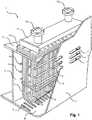
- Fig. 1shows as a basic embodiment, a schematic view of a cooling apparatus 1 for the cooling of a ship's engine, placed in a box defined by the hull 3 of the ship and partition plates 4, 5 such that entry and exit openings 6, 7 are provided on the hull 3 so that sea water can freely enter the box volume, flow over the cooling apparatus 1 and exit via natural flow, comprising a bundle of tubes 8 through which a fluid to be cooled can be conducted, at least one light source 9 for generating an anti-fouling light, arranged by the tubes 8 so as to emit the anti-fouling light on the tubes 8. Hot fluid enters the tubes 8 from above and conducted all the way and exits once again, now cooled from the top side.
- the light sources 9are arranged substantially perpendicular to the orientation of the tubes 8.
- Figs. 3 and 4show alternative embodiments of the cooling apparatus 1 wherein at least one light source 9 is interposed between at least two tube portions 18, 28, 38, 118, 228, 338 so that the light from the light source 9 is casted towards both tube portions 18, 28, 38, 118, 228, 338. Further the light sources 9 are arranged in parallel to each other.
- Fig. 3shows the embodiment where light sources 9 are arranged to emit light towards the inner side of the tube bundle and at least one light source 9 is arranged to emit light towards the outer side of the tube bundle.
- the cooling apparatuscomprises a tube bundle comprising tube layers arranged in parallel along its width.
- Each tube layercomprises a plurality of hairpin type tubes 8 comprising two straight tube portions 18, 28 and one semicircular tube portion 38.
- the tubes 8are disposed with their semicircular portions 38 concentrically arranged and their straight portions 18, 28 arranged in parallel, so that the innermost semicircular tube portions 38 are of relatively small radius and the outermost semicircular tube portions 38 are of relatively large radius, with the remaining intermediate semicircular tube portions 38 are of progressively graduated radius of curvature disposed therebetween.
- the tube bundleconforms with a rectangular prism shape with a half cylinder shape connected to the rectangular prism portion at the bottom end, as shown in Fig. 1 .
- the cooling apparatus 1is further provided with at least one lamella 16 that is at least partly in contact with the tubes 8 so as to increase the heat transfer.
- the lamella 16it is preferred for the lamella 16 to be positioned so as to direct the light from the light source 9 towards the sides of the tube portions 18, 28, 38, 118, 228, 338 which otherwise remain in the shadow.
- the cooling apparatus 1is provided with a plurality of vertical plate-shaped lamellas 16.
- Lamellas 16are positioned such that multiple tubes 8 are arranged in between two lamellas 16 and the light source 9 is positioned on either side of the lamellas 16 in a direction perpendicular to both the tubes 8 and the lamellas 16.
- the tube bundleconforms with an elongated cylindrical shape with a hemispherical shape connected to the cylindrical portion 38 at the bottom end. Accordingly more tubes 8 are provided in the central layers and the layers above and below the central layers have a gradually decreasing number of tubes 8, as shown in Fig. 2 . Accordingly, the outermost U-shaped tube portions 38 jointly define a generally hemispherical shape.
- the tube bundleis provided with a plurality of transverse plate-shaped lamellas 16 disposed in longitudinally spaced relation with each other and having the straight tube portions 18, 28, 118, 228 extending therethrough as shown in Fig. 2 and Fig. 6 , thereby to maintain the tubes 8 in fixed spaced relationship with each other throughout their lengths.
- the lamellas 16are provided with apertures for the straight tube portions 18, 28, 118, 228 to pass therethrough.
- the cooling apparatus 1 as shown in Fig. 2comprises a tube plate 10 on which the tubes 8 are mounted and a fluid header 11 connected to the tube plate 10 which comprises at least one inlet stub 12 and one outlet stub 13 for the entry and the exit of the fluid to and from the tubes 8 respectively.
- the cooling apparatus 1further comprises a sleeve 14 within which the light source 9 is placed so as to protect the light source 9 from outside effects.
- One end of the sleeve 14is attached to the fluid header 11 so as to provide ease of access for serviceability purposes.
- the light source 9will be accessible from the outside as well as the inlet stub 12 and the outlet stub 13, without a need for demounting the cooling apparatus 1 from the installed position.
- Figs. 8 and 9relate to an embodiment of the cooling apparatus 1 in which one centrally positioned light source 9 is used, extending in a vertical direction down from the fluid header 11, inside a protective sleeve 14.
- the cooling apparatus 1is furthermore equipped with a plurality of transverse plate-shaped lamellas 16 disposed in longitudinally spaced relation with each other and having the straight tube portions 18, 28 extending therethrough.
- the lamellas 16have various functions. In the first place the lamellas 16 serve to maintain the tubes 8 in fixed spaced relationship with each other throughout their lengths. To that end the lamellas 16 are provided with apertures for the straight tube portions 18, 28 to pass therethrough.
- the lamellas 16serve for enhancing heat transfer from the tubes 8 to the sea water.
- the lamellas 16are at least partly in contact with the tubes 8.
- both the tubes 8 and the lamellas 16comprise material having excellent thermal conductivity.
- the lamellas 16are positioned so as to direct the light from the light source 9 towards the tube portions 18, 28, which is especially the case when the lamellas 16 are at least partially coated with an antifouling light reflective coating.
- the tubes 8may be at least partially coated with such a coating as well.
- adjacent transverse lamellas 16 of the cooling apparatus 1 as shown in Figs. 8 and 9are arranged at a relatively short distance with respect to each other.
- the lamellas 16are not only provided with apertures for allowing the tubes 8 and the sleeve 14 containing the light source 9 to pass therethrough, but also with apertures 17 for allowing the sea water to pass therethrough.
- the tubes 8, the light source 9 and the lamellas 16are positioned relative to each other in such a way as to have minimal shadow effects in the cooling apparatus 1, which means that light from the light source 9 is capable of reaching almost every surface.
- the lightmay hit the lamellas 16 under a sharp angle, but it is still ensured that some of the light reaches the outer corners of the lamellas 16, i.e. the area of the lamellas 16 near the tubes 8.
- the lamellas 16are also kept free from bio-fouling under the influence of the light source 9.
- the assembly of the light source 9 and the protective sleeve 14extends through the fluid header 11.
- the protective sleeve 14has a circular periphery.
- a portion of the protective sleeve 14 as present in the fluid header 11may be incorporated in an internal construction 111 of the fluid header 11 which serves for separating the relatively hot fluid to be supplied to the tubes 8 from the relatively cool fluid discharged from the tubes 8.
- such a construction 111may have a cylinder-shaped portion 112 for constituting the portion of the protective sleeve 14, as can be seen in Fig. 8 in which the fluid header 11 is shown with an open side for the sake of illustration.
- the sleeve 14When it is necessary to remove the light source 9 from the cooling apparatus 1, it is possible to do so by removing a central cap 20 from the fluid header 11 and then pulling out the light source 9 in an upward vertical direction, wherein there is no need for taking the cooling apparatus 1 further apart, which is an important advantage of the arrangement of the sleeve 14 for accommodating the light source 9 according to which the sleeve 14 is vertically oriented while extending both through the fluid header 11 and between the various tubes 8. Also, putting the light source 9 back in place after having been removed is a process which can easily be performed.
- the sleeve 14it is also possible for the sleeve 14 to be removably arranged in the cooling apparatus 1. In such a case, it is advantageous if the cylinder-shaped portion 112 of the internal construction 111 of the fluid header 11 is arranged so as to encompass the portion of the sleeve 14 as present inside the fluid header 11.
- the lamellas 16may have apertures for allowing the tubes 8 to pass therethrough, as mentioned in the foregoing, but as an alternative, it is possible for the lamellas 16 to be formed as an integral whole with sections of the straight tube portions 18, 28 extending through the lamellas 16, which whole will hereinafter be referred to as lamella element.
- the tubes 8are realized by connecting a number of lamella elements to a portion of the tubes 8 extending down from the fluid header 11, wherein a first lamella element is attached to the portion of the tubes 8 as mentioned, a second lamella element is attached to the first lamella element, a third lamella element is attached to the second lamella element, etc.
- a U-shaped portion 38 of the tubes 8is attached to the last lamella element of the thus obtained stack of lamella elements in order to complete the tubes 8.
- lamella elements as mentionedare applied, a segmented appearance of the tubes 8 is obtained.
- the application of the lamella elementsmay contribute to facilitation of the manufacturing process of the cooling apparatus 1.
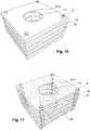
- Figs. 10, 11 and 12serve to illustrate the fact that as an alternative, hollow lamellas 16 may be used in the cooling apparatus 1.
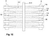
- the interior space 116 of the hollow lamellas 16is in direct communication with the tubes 8.
- the fluid to be cooledis not only transported through the tubes 8, but also through the lamellas 16.
- very effective transfer of heat to the sea wateris obtained, which allows for a design of the cooling apparatus 1 with a decreased number of tubes 8, for example, which may be beneficial to the anti-fouling effect of the light source 9 due to the fact that less obstacles are present in the path followed by the light that shines from the light source 9 during operation thereof.
- the hollow lamellas 16are provided with a central aperture 117 for allowing the assembly of the light source 9 and the sleeve 14 to pass therethrough.
- Fig. 10shows a perspective view of a number of hollow lamellas 16, portions of tubes 8 as present in the area of the cooling apparatus 1 where the lamellas 16 are located, and a portion of the assembly of the light source 9 and the sleeve 14.
- Fig. 11shows a similar view, with a section at one side for illustrating the fact that the interior space 116 of the lamellas 16 is open to the tubes 8. Also, structural lines which are hidden from sight in the representation of Fig. 10 are indicated by means of dotted lines in the representation of Fig. 11 .
- Fig. 12shows a sectional view of the lamellas 16, and furthermore shows the portions of tubes 8 and the portion of the assembly of the light source 9 and the sleeve 14 as shown in Figs.
- the hollow lamellas 16it is practical for the hollow lamellas 16 to be formed as an integral whole with sections of the straight tube portions 18, 28 extending through the lamellas 16 so that a portion of the cooling apparatus 1 having the lamellas 16 can be assembled by stacking lamella elements 115 comprising a combination of a lamella 16 and sections of the straight tube portions 18, 28 and interconnecting those lamella elements 115.
- Fig. 5shows another embodiment of the cooling apparatus 1.
- the cooling apparatus 1comprises longitudinal lamellas 16 extending in between two tube portions 18, 28, 118, 228 or between a tube portion 18, 28, 118, 228 and a light source 9 so as to enhance the heat transfer and/or the antifouling effect of the light source 9.
- the light source 9is positioned at the center, the tubes 8 are positioned in a cylindrical configuration around the light source 9 and the lamellas 16 are extending from each tube portion 18, 28, 118, 228 towards the central light source 9 as shown in Fig. 5 .
Landscapes
- Engineering & Computer Science (AREA)
- Mechanical Engineering (AREA)
- Physics & Mathematics (AREA)
- General Engineering & Computer Science (AREA)
- Thermal Sciences (AREA)
- Ocean & Marine Engineering (AREA)
- Combustion & Propulsion (AREA)
- Chemical & Material Sciences (AREA)
- Optics & Photonics (AREA)
- Geometry (AREA)
- Heat-Exchange Devices With Radiators And Conduit Assemblies (AREA)
- Arrangement Of Elements, Cooling, Sealing, Or The Like Of Lighting Devices (AREA)
- Physical Water Treatments (AREA)
Description
- The present disclosure relates to a cooling apparatus, according to
claim 1, which is adapted for the prevention of fouling, commonly referred to as anti-fouling. The disclosure specifically relates to anti-fouling of sea box coolers. - Bio-fouling or biological fouling is the accumulation of microorganisms, plants, algae, and/or animals on surfaces. The variety among bio-fouling organisms is highly diverse and extends far beyond attachment of barnacles and seaweeds. According to some estimates, over 1800 species comprising over 4000 organisms are responsible for bio-fouling. Bio-fouling is divided into microfouling which includes biofilm formation and bacterial adhesion, and macrofouling which is the attachment of larger organisms. Due to the distinct chemistry and biology that determine what prevents them from settling, organisms are also classified as hard or soft fouling types. Calcareous (hard) fouling organisms include barnacles, encrusting bryozoans, mollusks, polychaete and other tube worms, and zebra mussels. Examples of non-calcareous (soft) fouling organisms are seaweed, hydroids, algae and biofilm "slime". Together, these organisms form a fouling community.
- In several circumstances bio-fouling creates substantial problems. Machinery stops working, water inlets get clogged, and heat exchangers suffer from reduced performance. Hence the topic of anti-fouling, i.e. the process of removing or preventing bio-fouling from forming, is well known. In industrial processes, bio-dispersants can be used to control bio-fouling. In less controlled environments, organisms are killed or repelled with coatings using biocides, thermal treatments or pulses of energy. Nontoxic mechanical strategies that prevent organisms from attaching include choosing a material or coating with a slippery surface, or creation of nanoscale surface topologies similar to the skin of sharks and dolphins which only offer poor anchor points.
- Antifouling arrangements for cooling units that cool the engine fluid of a ship via seawater are known in the art.
DE102008029464 relates to a sea box cooler comprising an antifouling system by means of regularly repeatable overheating. Hot water is separately supplied to the heat exchanger tubes so as to minimize the fouling propagation on the tubes. US2014196745 relates to a system that includes a UV light source and an optical medium coupled to receive UV light from the UV light source. The optical medium is configured to emit UV light proximate to a surface from which biofouling is to be removed once the biofouling has adhered to the protected surface. The system furthermore includes a cleaning mechanism proximate to the protected surface and operable to remove biological material from the protected surface. Additionally or alternatively, the system comprises a degradable layer disposed over and mechanically coupled to the protected surface, wherein selected portions of the degradable layer are removable in response to UV light.EP 2 485 003 discloses a cooling apparatus according to the preamble ofclaim 1.- Bio-fouling of box coolers causes severe problems. The main issue is a reduced capacity for heat transfer as the thick layers of bio-fouling are effective heat insulators. As a result, the ship engines have to run at a much lower speed, slowing down the ship itself, or even come to a complete halt, due to over-heating.
- There are numerous organisms that contribute to bio-fouling. This includes very small organisms like bacteria and algae, but also very large ones such as crustaceans. The environment, temperature of the water, and purpose of the system all play a role here. The environment of a box cooler is ideally suited for bio-fouling: the fluid to be cooled heats up to a medium temperature and the constant flow of water brings in nutrients and new organisms.
- Accordingly methods and apparatus are necessary for anti-fouling. Prior art systems, however, may be inefficient in their use, require regular maintenance and in most cases result in ion discharge to the sea water with possible hazardous effects.
- Hence, it is an aspect of the invention to provide a cooling apparatus for the cooling of a ship's machinery with an alternative anti-fouling system according to the appended independent claims. The dependent claims define advantageous embodiments.
- Herewith an approach is presented based on optical methods, in particular using ultra-violet light (UV). It appears that most micro-organisms are killed, rendered inactive or unable to reproduce with 'sufficient' UV light. This effect is mainly governed by the total dose of UV light. A typical dose to kill 90% of a certain micro-organism is 10 mW-hours per square meter.
- The cooling apparatus for the cooling of a ship's machinery is suitable to be placed in a box that is defined by the hull of the ship and partition plates. Entry and exit openings are provided on the hull so that sea water can freely enter the box volume, flow over the cooling apparatus and exit via natural flow and/or under the influence of motion of the ship. The cooling apparatus comprises a bundle of tubes through which a fluid to be cooled can be conducted and at least one light source for generating an anti-fouling light, arranged by the tubes so as to emit anti-fouling light over the tubes' exterior surface.
- In an embodiment of the cooling apparatus the anti-fouling light emitted by the light source is in the UV or blue wavelength range from about 220nm to about 420nm, preferably about 260nm. Suitable anti-fouling levels are reached by UV or blue light from about 220nm to about 420nm, in particular at wavelengths shorter than about 300nm, e.g. from about 240nm to about 280nm which corresponds to what is known as UV-C. Anti-fouling light intensity in the range of 5-10 mW/m2 (milliwatts per square meter) can be used. Obviously higher doses of antifouling light would also achieve the same if not better results.
- The light source may be a lamp having a tubular structure in an embodiment of the cooling apparatus. For these light sources as they are rather big the light from a single source is generated over a large area. Accordingly it is possible to achieve the desired level of anti-fouling with a limited number of light sources which render the solution rather cost effective.
- A very efficient source for generating UVC is the low-pressure mercury discharge lamp, where on average 35% of input watts is converted to UVC watts. The radiation is generated almost exclusively at 254 nm viz. at 85% of the maximum germicidal effect. Low pressure tubular flourescent ultraviolet (TUV) lamps are known which have an envelope of special glass that filters out ozone-forming radiation.
- For various germicidal TUV lamps the electrical and mechanical properties are identical to their lighting equivalents for visible light. This allows them to be operated in the same way i.e. using an electronic or magnetic ballast/starter circuit. As with all low pressure lamps, there is a relationship between lamp operating temperature and output. For example, in low pressure lamps the resonance line at 254 nm is strongest at a certain mercury vapour pressure in the discharge tube. This pressure is determined by the operating temperature and optimises at a tube wall temperature of 40°C, corresponding with an ambient temperature of about 25°C. It should also be recognised that lamp output is affected by air currents (forced or natural) across the lamp, the so called chill factor. The reader should note that, for some lamps, increasing the air flow and/or decreasing the temperature can increase the germicidal output. This is met in high output (HO) lamps viz. lamps with higher wattage than normal for their linear dimension.
- A second type of UV source is the medium pressure mercury lamp, here the higher pressure excites more energy levels producing more spectral lines and a continuum (recombined radiation). It should be noted that the quartz envelope transmits below 240 nm so ozone can be formed from air. Advantages of medium pressure sources are:
- high power density;
- high power, resulting in fewer lamps than low pressure types being used in the same application; and
- less sensitivity to environment temperature.
- Further, Dielectric Barrier Discharge (DBD) lamps can be used. These lamps can provide very powerful UV light at various wavelengths and at high electrical-to-optical power efficiencies.
- The germicidal doses needed can also easily be achieved with existing low cost, lower power UV LEDs. LEDs can generally be included in relatively smaller packages and consume less power than other types of light sources. LEDs can be manufactured to emit (UV) light of various desired wavelengths and their operating parameters, most notably the output power, can be controlled to a high degree.
- In a particular embodiment of the cooling apparatus, the light sources are arranged substantially perpendicular to the orientation of the tubes. Accordingly it is provided that the anti-fouling light generated by the lamp to be scattered over various pipes. Hence the risk of a single pipe which is closer to the light source receiving and absorbing a big percentage of the light and the other pipes remaining in the shade of this first pipe is avoided.
- In a further particular embodiment of the cooling apparatus, the light sources are arranged in parallel to each other. Thus similar distribution of light over the entire cooling apparatus is achieved and any missed spots on the pipes are avoided and thus the anti-fouling efficiency is increased.
- In a further particular embodiment of the cooling apparatus the light source extends along the full width of the cooling apparatus. Thus the scattering of the emitted anti-fouling light to all the pipes are assured.
- In an embodiment of the present invention the cooling apparatus comprises a bundle of tubes wherein the tubes are U-shaped and at least one light source is arranged at the inner side center of the semicircular tube portion.
- In an embodiment of the present invention at least one light source is arranged to emit light towards the inner side of the tube bundle and at least one light source is arranged to emit light towards the outer side of the tube bundle. This configuration facilitates anti-fouling of both on the inner and the outer sides of the tubes.
- In a further embodiment of the present invention the tube bundle comprises tube layers arranged in parallel along its width such that each tube layer comprises a plurality of hairpin type tubes having two straight tube portions and one semicircular portion so as to form a U-shaped tube and wherein the tubes are disposed with U-shaped tube portions concentrically arranged and straight tube portions arranged in parallel, so that the innermost U-shaped tube portions are of relatively small radius and the outermost U-shaped tube portions are of relatively large radius, with the remaining intermediate U-shaped tube portions are of progressively graduated radius of curvature disposed therebetween.
- In a further aspect of the embodiment described above at least one light source is arranged at the inner side center of the innermost semicircular tube portion. Accordingly anti-fouling light is more efficiently scattered on the inner side of the rounding bottom of the U.
- In an embodiment of the present invention the tube bundle conforms to a rectangular prism shape with a half cylinder shape connected to the rectangular prism portion at the bottom end and at least one of the light sources is arranged to lie on or in parallel to the axis line of the said cylinder.
- In an embodiment of the present invention the tube bundle conforms with an elongated cylindrical shape with a hemispherical shape connected to the cylindrical portion at the bottom end and at least one of the light sources is arranged to lie on or in parallel to the axis line of the said cylinder.
- In an embodiment of the present invention at least one light source is arranged in-between each tube. In an embodiment the cooling apparatus comprises a plurality of transverse lamellas on the tube bundle disposed in longitudinally spaced relation with each other and having the straight tube portions extending therethrough, thereby to maintain the tubes in fixed spaced relationship with each other throughout their lengths. According to the invention, the lamellas are in contact with the tubes, the lamellas may contribute to heat transfer from the tubes so that a similar amount of heat transfer can be achieved with fewer tubes and thus the amount of shadow cast by tubes among other tubes is minimized thereby increasing the antifouling efficiency. The lamellas may be of any suitable shape and may be shaped like plates, for example. It is furthermore possible for the lamellas to be provided with two types of apertures, namely one type of aperture for allowing the tubes to pass through and another type of aperture for realizing that a flow of cooling medium such as water along the tubes is hindered only to a minimum extent by the presence of the lamellas. According to another option, the lamellas may be hollow so as to be capable of communicating with the tubes and transporting the fluid to be cooled in order to achieve an even larger contribution of the lamellas to the heat transfer. According to yet another option, each of the lamellas may be formed as an integral whole with a number of sections of tube portions extending through the lamellas. This option may be advantageous in view of the manufacturing process of the cooling apparatus, as according to this option, putting the lamellas in place with respect to the tubes requires nothing more than stacking the lamellas and interconnecting the sections of the tube portions.
- In an embodiment the cooling apparatus comprises a plurality of longitudinal lamellas on the tube bundle extending in between two tube portions or between a tube portion and a light source. Accordingly similar to the embodiment above enhanced heat transfer and antifouling properties are achieved.
- In further variation of the above embodiment the light source is positioned at the center, the tubes are positioned in a cylindrical configuration around the light source and the lamellas are extending from each straight tube portion towards the central light source. In this embodiment the cooling apparatus is actually a circular style heat exchanger and the light source is arranged in center of the heat exchanger such that it would lie in parallel with the straight tube portions.
- In an embodiment of the cooling apparatus the light sources are arranged such that there exists at least one light source in between each tube. Accordingly the risk of the tubes casting a shade over each other is mitigated and a desired level of anti-fouling is achieved.
- In an embodiment of the cooling apparatus the tubes and/or the lamellas are at least partially coated with a light reflective coating. Advantageously, the light reflective coating is adapted to cause the antifouling light to reflect in a diffuse way so that light is distributed more effectively over the tubes.
- In an embodiment of the cooling apparatus the light source is placed in a sleeve to protect the light source from outside effects.
- In an embodiment of the cooling apparatus the cooling apparatus comprises a tube plate on which the tubes are mounted, and connected to the tube plate a fluid header comprising one inlet stub and one outlet stub for the entry and the exit of the fluid to and from the tubes respectively. In a version of this embodiment one end of the sleeve is attached to the fluid header. Accordingly when installed in a final usage location the light source will be accessible from the outside as well as the inlet stub and the outlet stub, without a need for demounting the cooling apparatus from the installed position.
- In an embodiment of the cooling apparatus the cooling apparatus is arranged for avoiding shadows over substantially the entire submerged portion of the exterior of the tube, so that this portion is protected from fouling.
- In a version of the above-mentioned embodiment the shadows are avoided by positioning the light source with respect to the tubes. The shadows may be avoided by positioning the light source substantially perpendicular to the orientation of the tubes and/or when the tubes are U-shaped by the light source being arranged at the inner side center of the rounding bottom of the tubes. Alternatively shadows may also be avoided by decreasing damping of the light, for example by increasing reflection of the light.
- The invention furthermore relates to a cooling apparatus as mentioned in the foregoing, in a situation prior to installation of the at least one light source, i.e. a cooling apparatus comprising a bundle of tubes for containing and transporting fluid in their interior, the exterior of the tubes being in operation at least partially submerged in water so as to cool the tube to thereby also cool the fluid, a tube plate on which the tubes are mounted and to which the tubes are connected, a fluid header comprising an inlet stub and an outlet stub for the entry and the exit of the fluid to and from the tubes respectively, the apparatus being adapted to receive at least one light source for producing light that hinders fouling by casting anti-fouling light over the tubes' exterior, preferably the adaptation comprising a sleeve for accommodating the light source, the sleeve being attached to the fluid header so as to allow the light source to be arranged therein to be accessible from the outside.
- The invention also provides a ship comprising a cooling apparatus as described above. In such an embodiment the inner surfaces of the box in which the cooling apparatus is placed may be at least partially coated with a light reflective coating. Similarly to the embodiment above as a result of this particular embodiment the anti-fouling light can be made to reflect in a diffuse way so that light is distributed more effectively over the tubes. Furthermore in such an embodiment the light source may be associated with an inner surface of the box in any suitable manner, particularly be part of or connected to or attached to the inner surface of the box.
- The term "substantially" herein, such as in "substantially parallel" or in "substantially perpendicular", will be understood by the person skilled in the art. The term "substantially" may also include embodiments with "entirely", "completely", "all", etc. Hence, in embodiments the adjective substantially may also be removed. Where applicable, the term "substantially" may also relate to 90% or higher, such as 95% or higher, especially 99% or higher, even more especially 99.5% or higher, including 100%. The term "comprise" includes also embodiments wherein the term "comprises" means "consists of'. The term "comprising" may in an embodiment refer to "consisting of" but may in another embodiment also refer to "containing at least the defined species and optionally one or more other species".
- It is to be understood that the terms so used are interchangeable under appropriate circumstances and that the embodiments of the invention described herein are capable of operation in other sequences than described or illustrated herein.
- It should be noted that the above-mentioned embodiments illustrate rather than limit the invention, and that those skilled in the art will be able to design many alternative embodiments without departing from the scope of the appended claims. In the claims, any reference signs placed between parentheses shall not be construed as limiting the claim. The article "a" or "an" preceding an element does not exclude the presence of a plurality of such elements. The mere fact that certain measures are recited in mutually different dependent claims does not indicate that a combination of these measures cannot be used to advantage.
- The invention further applies to a device comprising one or more of the characterizing features described in the description and/or shown in the attached drawings.
- The various aspects discussed in this patent can be combined in order to provide additional advantages. Furthermore, some of the features can form the basis for one or more divisional applications.
- Embodiments of the invention will now be described, by way of example only, with reference to the accompanying schematic drawings in which corresponding reference symbols indicate corresponding parts, and in which:
Fig. 1 is a schematic representation of an embodiment of the cooling apparatus;Fig. 2 is a schematic representation of another embodiment of the cooling apparatus;Fig. 3 is a schematic vertical cross section view of an embodiment of the cooling apparatus;Fig. 4 is a schematic vertical cross section view of another embodiment of the cooling apparatus;Fig. 5 is a schematic horizontal cross section view of yet another embodiment of the cooling apparatus;Fig. 6 is a schematic horizontal cross section view of the embodiment of the cooling apparatus as shown inFig. 2 ;Fig. 7 is a schematic horizontal cross section view of an alternative embodiment of the cooling apparatus as described herein;Figs. 8 and 9 are schematic representations of yet another alternative embodiment of the cooling apparatus as described herein;Figs. 10 and 11 are schematic representations of a portion of a further embodiment of the cooling apparatus as described herein; andFig. 12 is a schematic vertical cross section view of the portion of the embodiment of the cooling apparatus as shown inFigs. 10 and 11 .- The drawings are not necessarily on scale.
- While the disclosure has been illustrated and described in detail in the drawings and foregoing description, such illustration and description are to be considered illustrative or exemplary and not restrictive; the disclosure is not limited to the disclosed embodiments. It is further noted that the drawings are schematic, not necessarily to scale and that details that are not required for understanding the present invention may have been omitted. The terms "inner", "outer", "along", "longitudinal", "bottom" and the like relate to the embodiments as oriented in the drawings, unless otherwise specified. Further, elements that are at least substantially identical or that perform an at least substantially identical function are denoted by the same numeral.
Fig. 1 shows as a basic embodiment, a schematic view of acooling apparatus 1 for the cooling of a ship's engine, placed in a box defined by thehull 3 of the ship andpartition plates exit openings hull 3 so that sea water can freely enter the box volume, flow over thecooling apparatus 1 and exit via natural flow, comprising a bundle oftubes 8 through which a fluid to be cooled can be conducted, at least onelight source 9 for generating an anti-fouling light, arranged by thetubes 8 so as to emit the anti-fouling light on thetubes 8. Hot fluid enters thetubes 8 from above and conducted all the way and exits once again, now cooled from the top side. Meanwhile sea water enters the box from theentry openings 6, flows over thetubes 8 and receives heat from thetubes 8 and thus the fluid conducted within. Taking the heat from thetubes 8 sea water warms up and rises. The sea water then exits the box from theexit openings 7 which are located at a higher point on thehull 3. During this cooling process any bio organisms existing in the sea water tend to attach to thetubes 8 which are warm and provide a suitable environment for the organisms to live in, the phenomena known as fouling. To avoid such attachment at least onelight source 9 is arranged by thetubes 8. Thelight source 9 emits the anti-fouling light on the outer surface of thetubes 8. Accordingly fouling formation is avoided. As illustrated inFig. 1 one or more tubular lamps can be used as alight source 9 to realize the aim of the invention.- As shown in
Fig. 1 in an embodiment of the invention thelight sources 9 are arranged substantially perpendicular to the orientation of thetubes 8. Figs. 3 and 4 show alternative embodiments of thecooling apparatus 1 wherein at least onelight source 9 is interposed between at least twotube portions light source 9 is casted towards bothtube portions light sources 9 are arranged in parallel to each other.Fig. 3 shows the embodiment wherelight sources 9 are arranged to emit light towards the inner side of the tube bundle and at least onelight source 9 is arranged to emit light towards the outer side of the tube bundle.- In an embodiment the cooling apparatus comprises a tube bundle comprising tube layers arranged in parallel along its width. Each tube layer comprises a plurality of
hairpin type tubes 8 comprising twostraight tube portions semicircular tube portion 38. Thetubes 8 are disposed with theirsemicircular portions 38 concentrically arranged and theirstraight portions semicircular tube portions 38 are of relatively small radius and the outermostsemicircular tube portions 38 are of relatively large radius, with the remaining intermediatesemicircular tube portions 38 are of progressively graduated radius of curvature disposed therebetween. - In one variation of the above embodiment the tube bundle conforms with a rectangular prism shape with a half cylinder shape connected to the rectangular prism portion at the bottom end, as shown in
Fig. 1 . - In an embodiment the
cooling apparatus 1 is further provided with at least onelamella 16 that is at least partly in contact with thetubes 8 so as to increase the heat transfer. In appropriate cases, especially cases in which a plurality oftubes 8 are present in a tube layer, it is preferred for thelamella 16 to be positioned so as to direct the light from thelight source 9 towards the sides of thetube portions - In a version of the above embodiment as shown in
Fig. 7 , thecooling apparatus 1 is provided with a plurality of vertical plate-shapedlamellas 16.Lamellas 16 are positioned such thatmultiple tubes 8 are arranged in between two lamellas 16 and thelight source 9 is positioned on either side of the lamellas 16 in a direction perpendicular to both thetubes 8 and thelamellas 16. - In another variation of the above embodiment the tube bundle conforms with an elongated cylindrical shape with a hemispherical shape connected to the
cylindrical portion 38 at the bottom end. Accordinglymore tubes 8 are provided in the central layers and the layers above and below the central layers have a gradually decreasing number oftubes 8, as shown inFig. 2 . Accordingly, the outermostU-shaped tube portions 38 jointly define a generally hemispherical shape. - In an embodiment the tube bundle is provided with a plurality of transverse plate-shaped
lamellas 16 disposed in longitudinally spaced relation with each other and having thestraight tube portions Fig. 2 andFig. 6 , thereby to maintain thetubes 8 in fixed spaced relationship with each other throughout their lengths. Thelamellas 16 are provided with apertures for thestraight tube portions - In an embodiment the
cooling apparatus 1 as shown inFig. 2 comprises atube plate 10 on which thetubes 8 are mounted and afluid header 11 connected to thetube plate 10 which comprises at least oneinlet stub 12 and oneoutlet stub 13 for the entry and the exit of the fluid to and from thetubes 8 respectively. In this embodiment thecooling apparatus 1 further comprises asleeve 14 within which thelight source 9 is placed so as to protect thelight source 9 from outside effects. One end of thesleeve 14 is attached to thefluid header 11 so as to provide ease of access for serviceability purposes. In particular, when installed in a final usage location thelight source 9 will be accessible from the outside as well as theinlet stub 12 and theoutlet stub 13, without a need for demounting thecooling apparatus 1 from the installed position. Figs. 8 and 9 relate to an embodiment of thecooling apparatus 1 in which one centrally positionedlight source 9 is used, extending in a vertical direction down from thefluid header 11, inside aprotective sleeve 14. In this embodiment thecooling apparatus 1 is furthermore equipped with a plurality of transverse plate-shapedlamellas 16 disposed in longitudinally spaced relation with each other and having thestraight tube portions lamellas 16 have various functions. In the first place thelamellas 16 serve to maintain thetubes 8 in fixed spaced relationship with each other throughout their lengths. To that end thelamellas 16 are provided with apertures for thestraight tube portions lamellas 16 serve for enhancing heat transfer from thetubes 8 to the sea water. To that end thelamellas 16 are at least partly in contact with thetubes 8. Preferably both thetubes 8 and thelamellas 16 comprise material having excellent thermal conductivity. In the third place thelamellas 16 are positioned so as to direct the light from thelight source 9 towards thetube portions lamellas 16 are at least partially coated with an antifouling light reflective coating. Thetubes 8 may be at least partially coated with such a coating as well.- In comparison with the
transverse lamellas 16 as shown inFig. 2 , adjacenttransverse lamellas 16 of thecooling apparatus 1 as shown inFigs. 8 and 9 are arranged at a relatively short distance with respect to each other. In order for the flow of sea water through thecooling apparatus 1 not to be hindered too much, thelamellas 16 are not only provided with apertures for allowing thetubes 8 and thesleeve 14 containing thelight source 9 to pass therethrough, but also withapertures 17 for allowing the sea water to pass therethrough. - In the configuration of the
cooling apparatus 1 as shown inFigs. 8 and 9 , thetubes 8, thelight source 9 and thelamellas 16 are positioned relative to each other in such a way as to have minimal shadow effects in thecooling apparatus 1, which means that light from thelight source 9 is capable of reaching almost every surface. The light may hit thelamellas 16 under a sharp angle, but it is still ensured that some of the light reaches the outer corners of thelamellas 16, i.e. the area of thelamellas 16 near thetubes 8. Hence, thelamellas 16 are also kept free from bio-fouling under the influence of thelight source 9. - The assembly of the
light source 9 and theprotective sleeve 14 extends through thefluid header 11. In the shown example theprotective sleeve 14 has a circular periphery. A portion of theprotective sleeve 14 as present in thefluid header 11 may be incorporated in aninternal construction 111 of thefluid header 11 which serves for separating the relatively hot fluid to be supplied to thetubes 8 from the relatively cool fluid discharged from thetubes 8. In particular, such aconstruction 111 may have a cylinder-shapedportion 112 for constituting the portion of theprotective sleeve 14, as can be seen inFig. 8 in which thefluid header 11 is shown with an open side for the sake of illustration. When it is necessary to remove thelight source 9 from thecooling apparatus 1, it is possible to do so by removing acentral cap 20 from thefluid header 11 and then pulling out thelight source 9 in an upward vertical direction, wherein there is no need for taking thecooling apparatus 1 further apart, which is an important advantage of the arrangement of thesleeve 14 for accommodating thelight source 9 according to which thesleeve 14 is vertically oriented while extending both through thefluid header 11 and between thevarious tubes 8. Also, putting thelight source 9 back in place after having been removed is a process which can easily be performed. Within the framework of the invention, it is also possible for thesleeve 14 to be removably arranged in thecooling apparatus 1. In such a case, it is advantageous if the cylinder-shapedportion 112 of theinternal construction 111 of thefluid header 11 is arranged so as to encompass the portion of thesleeve 14 as present inside thefluid header 11. - It is noted that the
lamellas 16 may have apertures for allowing thetubes 8 to pass therethrough, as mentioned in the foregoing, but as an alternative, it is possible for the lamellas 16 to be formed as an integral whole with sections of thestraight tube portions lamellas 16, which whole will hereinafter be referred to as lamella element. In that case, during assembly of thecooling apparatus 1, thetubes 8 are realized by connecting a number of lamella elements to a portion of thetubes 8 extending down from thefluid header 11, wherein a first lamella element is attached to the portion of thetubes 8 as mentioned, a second lamella element is attached to the first lamella element, a third lamella element is attached to the second lamella element, etc. AU-shaped portion 38 of thetubes 8 is attached to the last lamella element of the thus obtained stack of lamella elements in order to complete thetubes 8. Hence, when lamella elements as mentioned are applied, a segmented appearance of thetubes 8 is obtained. The application of the lamella elements may contribute to facilitation of the manufacturing process of thecooling apparatus 1. Figs. 10, 11 and12 serve to illustrate the fact that as an alternative,hollow lamellas 16 may be used in thecooling apparatus 1. In that case, theinterior space 116 of thehollow lamellas 16 is in direct communication with thetubes 8. Thus, during operation of thecooling apparatus 1, the fluid to be cooled is not only transported through thetubes 8, but also through thelamellas 16. In that way, very effective transfer of heat to the sea water is obtained, which allows for a design of thecooling apparatus 1 with a decreased number oftubes 8, for example, which may be beneficial to the anti-fouling effect of thelight source 9 due to the fact that less obstacles are present in the path followed by the light that shines from thelight source 9 during operation thereof. For the sake of completeness, it is noted that thehollow lamellas 16 are provided with acentral aperture 117 for allowing the assembly of thelight source 9 and thesleeve 14 to pass therethrough.Fig. 10 shows a perspective view of a number ofhollow lamellas 16, portions oftubes 8 as present in the area of thecooling apparatus 1 where thelamellas 16 are located, and a portion of the assembly of thelight source 9 and thesleeve 14.Fig. 11 shows a similar view, with a section at one side for illustrating the fact that theinterior space 116 of thelamellas 16 is open to thetubes 8. Also, structural lines which are hidden from sight in the representation ofFig. 10 are indicated by means of dotted lines in the representation ofFig. 11 .Fig. 12 shows a sectional view of thelamellas 16, and furthermore shows the portions oftubes 8 and the portion of the assembly of thelight source 9 and thesleeve 14 as shown inFigs. 10 and 11 . It is practical for thehollow lamellas 16 to be formed as an integral whole with sections of thestraight tube portions lamellas 16 so that a portion of thecooling apparatus 1 having thelamellas 16 can be assembled by stackinglamella elements 115 comprising a combination of alamella 16 and sections of thestraight tube portions lamella elements 115.Fig. 5 shows another embodiment of thecooling apparatus 1. In this embodiment thecooling apparatus 1 compriseslongitudinal lamellas 16 extending in between twotube portions tube portion light source 9 so as to enhance the heat transfer and/or the antifouling effect of thelight source 9.- In a preferred version of this embodiment the
light source 9 is positioned at the center, thetubes 8 are positioned in a cylindrical configuration around thelight source 9 and thelamellas 16 are extending from eachtube portion light source 9 as shown inFig. 5 . - Elements and aspects discussed for or in relation with a particular embodiment may be suitably combined with elements and aspects of other embodiments, unless explicitly stated otherwise. The invention has been described with reference to the preferred embodiments. Modifications and alterations may occur to others upon reading and understanding the preceding detailed description. It is intended that the invention be construed as including all such modifications and alterations insofar as they come within the scope of the appended claims or the equivalents thereof. As fouling may also happen in rivers or lakes or any other area where the cooling apparatus is in contact with water, the invention is generally applicable to cooling by means of water.
Claims (26)
- A cooling apparatus (1) for cooling a fluid by means of surface water, the cooling apparatus comprising:- at least one tube (8) for containing and transporting the fluid in its interior, the exterior of the tube (8) being in operation at least partially submerged in the surface water so as to cool the tube (8) to thereby also cool the fluid,
characterized in that- the cooling apparatus is adapted to receive at least one light source (9) for producing light that hinders fouling,wherein, the at least one light source (9) is dimensioned and positioned with respect to the tube (8) so as to cast anti-fouling light over the tubes' (8) exterior, wherein the cooling apparatus further comprises:- at least one lamella (16) that is at least partly in contact with the tubes (8), wherein optionally the lamella (16) is hollow, the interior space (116) of the lamella (16) being in direct communication with the tubes (8), and wherein optionally the lamella (16) is formed as an integral whole with a number of sections of tube portions (18, 28, 118, 228). - A cooling apparatus (1) according to Claim 1, wherein at least one light source (9) is interposed between at least two tube portions (18, 28, 38, 118, 228, 338) so that the light from the light source (9) is casted towards both tube portions (18, 28, 38, 118, 228, 338).
- A cooling apparatus (1) according to any preceeding Claim, wherein the light source (9) is a tubular lamp.
- A cooling apparatus (1) according to any preceding Claim, wherein at least one light source (9) is arranged substantially perpendicular to the orientation of the tubes (8).
- A cooling apparatus (1) according to any preceeding Claim, wherein the light sources (9) are arranged substantially in parallel to each other.
- A cooling apparatus (1) according to any preceeding Claim, wherein the light source extends along the full width of the cooling apparatus.
- A cooling apparatus (1) according to any preceding Claim, comprising a bundle of tubes wherein at least one light source (9) is arranged to emit light towards the inner side of the tube bundle and at least one light source (9) is arranged to emit light towards the outer side of the tube bundle.
- A cooling apparatus (1) according to any preceding Claim, wherein the tubes (8) are U-shaped and at least one light source (119) is arranged at the inner side center of the semicircular tube portion (38).
- A cooling apparatus (1) according to Claims 7 or 8, wherein a tube bundle comprises tube layers arranged in parallel along its width such that each tube layer comprises a plurality of hairpin type tubes (8) having two straight tube portions (18, 28) and one semicircular portion (38) so as to form a U-shaped tube (8) and wherein the tubes (8) are disposed with U-shaped tube portions (38) concentrically arranged and straight tube portions (18, 28) arranged in parallel, so that the innermost U-shaped tube portions (38) are of relatively small radius and the outermost U-shaped tube portions (38) are of relatively large radius, with the remaining intermediate U-shaped tube portions (38) are of progressively graduated radius of curvature disposed there-between wherein at least one light source (119) is arranged at the inner side center of the innermost semicircular tube portion (38).
- A cooling apparatus (1) according to any one of Claims 7 to 9, wherein the tube bundle conforms with a rectangular prism shape with a half cylinder shape connected to the rectangular prism portion at the bottom end and at least one of the light sources (9) is arranged to lie on or in parallel to the axis line of the said cylinder.
- A cooling apparatus (1) according to any one of Claims 7 to 9, wherein the tube bundle conforms to an elongated cylindrical shape with a hemispherical shape connected to the cylindrical portion at the bottom end and at least one of the light sources (9) is arranged to lie on or in parallel to the axis line of the said cylinder.
- A cooling apparatus (1) according to Claim 1, wherein the light source (9) and the at least one lamella (16) are positioned relative to each other to have light from the light source hit the at least one lamella (16) under a sharp angle.
- A cooling apparatus (1) according to any preceding Claim, comprising a plurality of transverse lamellas on a tube bundle disposed in longitudinally spaced relation with each other and having the straight tube portions extending therethrough.
- A cooling apparatus (1) according to Claim 13, wherein the lamellas are shaped like plates.
- A cooling apparatus (1) according to any of the preceding Claims, wherein the cooling apparatus comprises a sleeve to protect the light source from outside effects.
- A cooling apparatus (1) according to Claim 15, wherein one sleeve is centrally positioned.
- A cooling apparatus (1) according to any preceding Claim, comprising a tube plate on which the tubes are mounted, and connected to the tube plate a fluid header comprising one inlet stub and one outlet stub for the entry and the exit of the fluid to and from the tubes respectively.
- A cooling apparatus (1) according to any preceding Claim, wherein the tubes (8) and/or the lamellas (16) are at least partially coated with an antifouling light reflective coating.
- A cooling apparatus (1) according to any preceding Claim, wherein the cooling apparatus is arranged for avoiding shadows over substantially the entire submerged portion of the exterior of the tube, so that this portion is protected from fouling.
- A cooling apparatus (1) according to Claim 19, wherein the shadows are avoided by positioning the light source with respect to the tubes.
- A cooling apparatus (1) according to Claim 20, wherein the light source is to be positioned substantially perpendicular to the orientation of the tubes and/or when the tubes are U-shaped by the light source being arranged at the inner side center of the rounding bottom of the tubes.
- A cooling apparatus (1) according to Claim 20, wherein shadows are avoided by decreasing damping of the light.
- A cooling apparatus (1) according to Claim 22, wherein damping is decreased by increasing reflection of the light.
- A ship comprising a cooling apparatus (1) according to any preceding Claim for cooling of the ship's machinery.
- A ship according to Claim 24, wherein the cooling apparatus (1) is placed in a box, defined by the hull (3) of the ship and partition plates (4, 5) such that entry and exit openings (6, 7) are provided on the hull (3) so that sea water can freely enter the box volume, flow over the cooling apparatus (1) and exit via natural flow and wherein the inner surfaces of the box in which the cooling apparatus (1) is placed are at least partially coated with an antifouling light reflective coating.
- A ship comprising a cooling apparatus (1) according to any of Claims 1-23, wherein the cooling apparatus (1) is placed in a box, defined by the hull (3) of the ship and partition plates (4, 5) such that entry and exit openings (6, 7) are provided on the hull (3) so that sea water can enter the box volume, flow over the cooling apparatus (1) and exit the box, and wherein the light source (9) is part of or connected to or attached to an inner surface of the box.
Applications Claiming Priority (4)
| Application Number | Priority Date | Filing Date | Title |
|---|---|---|---|
| EP14197744 | 2014-12-12 | ||
| EP15177631 | 2015-07-21 | ||
| PCT/EP2015/078612WO2016091732A1 (en) | 2014-12-12 | 2015-12-04 | Cooling apparatus for cooling a fluid by means of surface water |
| EP15804786.0AEP3230675B1 (en) | 2014-12-12 | 2015-12-04 | Cooling apparatus for cooling a fluid by means of surface water |
Related Parent Applications (2)
| Application Number | Title | Priority Date | Filing Date |
|---|---|---|---|
| EP15804786.0ADivisionEP3230675B1 (en) | 2014-12-12 | 2015-12-04 | Cooling apparatus for cooling a fluid by means of surface water |
| EP15804786.0ADivision-IntoEP3230675B1 (en) | 2014-12-12 | 2015-12-04 | Cooling apparatus for cooling a fluid by means of surface water |
Publications (2)
| Publication Number | Publication Date |
|---|---|
| EP3483547A1 EP3483547A1 (en) | 2019-05-15 |
| EP3483547B1true EP3483547B1 (en) | 2020-08-12 |
Family
ID=54782719
Family Applications (2)
| Application Number | Title | Priority Date | Filing Date |
|---|---|---|---|
| EP18207188.6AActiveEP3483547B1 (en) | 2014-12-12 | 2015-12-04 | Cooling apparatus for cooling a fluid by means of surface water |
| EP15804786.0AActiveEP3230675B1 (en) | 2014-12-12 | 2015-12-04 | Cooling apparatus for cooling a fluid by means of surface water |
Family Applications After (1)
| Application Number | Title | Priority Date | Filing Date |
|---|---|---|---|
| EP15804786.0AActiveEP3230675B1 (en) | 2014-12-12 | 2015-12-04 | Cooling apparatus for cooling a fluid by means of surface water |
Country Status (8)
| Country | Link |
|---|---|
| US (3) | US10228199B2 (en) |
| EP (2) | EP3483547B1 (en) |
| JP (2) | JP6927878B2 (en) |
| KR (1) | KR102531768B1 (en) |
| CN (2) | CN107003094B (en) |
| BR (1) | BR112017012095B1 (en) |
| RU (2) | RU2758176C2 (en) |
| WO (1) | WO2016091732A1 (en) |
Families Citing this family (10)
| Publication number | Priority date | Publication date | Assignee | Title |
|---|---|---|---|---|
| CN107003094B (en) | 2014-12-12 | 2021-07-30 | 皇家飞利浦有限公司 | Cooling device for cooling fluid by means of surface water |
| KR102538941B1 (en)* | 2014-12-12 | 2023-06-01 | 코닌클리케 필립스 엔.브이. | Cooling apparatus for cooling a fluid by means of surface water |
| CN106370031A (en)* | 2016-10-31 | 2017-02-01 | 济南丰源塑料有限公司 | Plastic heat exchanger |
| CN106895721B (en)* | 2017-04-17 | 2023-08-01 | 广西玉柴机器股份有限公司 | Marine heat exchange assembly structure |
| KR102337341B1 (en) | 2017-07-28 | 2021-12-09 | 현대모비스 주식회사 | Curved display device for automotive and manufacturing method thereof |
| CN108020098A (en)* | 2017-12-13 | 2018-05-11 | 广新海事重工股份有限公司 | Green energy-conserving heat exchanger of boats and ships |
| CN108502123A (en)* | 2018-04-18 | 2018-09-07 | 天津艾孚森科技发展有限公司 | A method of removing hull bottom marine fouling organism |
| CN110864570B (en)* | 2019-11-26 | 2021-07-02 | 南通旭日船用机械有限公司 | Seawater corrosion resistant titanium pipe outboard cooler |
| JP7647334B2 (en)* | 2021-05-28 | 2025-03-18 | 中国電力株式会社 | Marine Life Control Device |
| NL2036722B1 (en)* | 2023-12-29 | 2025-07-15 | Corrosion & Water Control Shared Services B V | Heat exchanger configured to be mounted in the sea box of a vessel |
Family Cites Families (39)
| Publication number | Priority date | Publication date | Assignee | Title |
|---|---|---|---|---|
| US3624326A (en) | 1969-04-04 | 1971-11-30 | Westinghouse Electric Corp | Compressed-gas circuit breaker with readily removable terminal bushing means |
| JPS588811B2 (en)* | 1979-04-10 | 1983-02-17 | マルイ工業株式会社 | Method for suppressing and removing green algae growth |
| JPS60159596A (en) | 1984-01-30 | 1985-08-21 | Agency Of Ind Science & Technol | Prevention of stain by living organism |
| JPS61130843A (en)* | 1984-11-30 | 1986-06-18 | Mitsubishi Heavy Ind Ltd | Leak test for heat exchanger |
| JPS63162091A (en)* | 1986-12-24 | 1988-07-05 | Hitachi Ltd | Device for preventing sticking of aquatic living matter |
| JPS6419489A (en) | 1987-07-15 | 1989-01-23 | Hitachi Ltd | Handwritten character input device |
| JP2685824B2 (en)* | 1988-08-08 | 1997-12-03 | 東京電力株式会社 | Aquatic organism adhesion prevention device |
| JP3201792B2 (en)* | 1991-07-23 | 2001-08-27 | 東光電気株式会社 | Method for preventing adhesion of marine organisms in LNG evaporator |
| US5322569A (en)* | 1991-10-08 | 1994-06-21 | General Dynamics Corporation | Ultraviolet marine anti-biofouling systems |
| JPH0978552A (en)* | 1995-09-11 | 1997-03-25 | Bridgestone Corp | Offshore structure |
| JPH1019489A (en)* | 1996-06-28 | 1998-01-23 | Mitsubishi Heavy Ind Ltd | Heat transfer pipe support structure for pipe type heat-exchanger |
| JPH10103896A (en)* | 1996-09-30 | 1998-04-24 | Tokyo Electric Power Co Inc:The | Open rack type vaporizer sprinkler |
| WO1998056872A1 (en)* | 1997-06-10 | 1998-12-17 | Exxon Chemical Patents Inc. | Pyrolysis furnace with an internally finned u-shaped radiant coil |
| DE19960037A1 (en)* | 1999-06-17 | 2001-06-21 | Scharf Eva Maria | Method and device for preventing fouling in sea boxes and sea water systems on ships, offshore platforms, etc. |
| NL1013224C2 (en) | 1999-10-06 | 2001-04-09 | Bloksma B V | Box cooler. |
| US7077190B2 (en)* | 2001-07-10 | 2006-07-18 | Denso Corporation | Exhaust gas heat exchanger |
| JP4228385B2 (en)* | 2002-02-12 | 2009-02-25 | 三菱自動車工業株式会社 | Oil cooler built-in speed reducer |
| JP2005533632A (en)* | 2002-05-13 | 2005-11-10 | グリーンフューエル テクノロジーズ コーポレイション | Photobioreactor and process for biomass production and mitigation of pollutants in fuel gas |
| US20060266042A1 (en)* | 2005-05-27 | 2006-11-30 | Levine Michael R | Submerged condenser for steam power plant |
| CN1611870A (en)* | 2003-10-30 | 2005-05-04 | 乐金电子(天津)电器有限公司 | Photocatalyst-coated condensator capable of preventing dust from being adhesion |
| JP2006010208A (en)* | 2004-06-25 | 2006-01-12 | Kantoo:Kk | Heat exchanger also serving for sterilization |
| JP5137379B2 (en)* | 2005-11-14 | 2013-02-06 | インターナショナル・ビジネス・マシーンズ・コーポレーション | Collision cooler |
| DE102008006464A1 (en) | 2007-07-20 | 2009-01-22 | Koenig & Bauer Aktiengesellschaft | Revolving pre-gripper for sheet guiding from feed table to transfer drum has at least one revolving sheet holding system accommodated in right-hand guide track and in left-hand guide track, wherein guide tracks form closed curved line |
| CL2008001565A1 (en) | 2008-05-29 | 2008-08-29 | Ochoa Disselkoen Jose Alberto | SUBMERSIBLE FLOATING DEVICE, FOR BIOLOGICAL CLEANING OF NETWORKS USED IN THE CROP OF FISH THAT ALLOWS TO DESTROY THE MICROORGANISMS OF WATER, CONFORMED BY SUPPORTING MEANS, A FILTER MEDIA AND A DISINFECTION MEDIA |
| DE102008029464B4 (en) | 2008-06-20 | 2013-02-07 | Gunter Höffer | Sea chest coolers on ships and offshore platforms with integrated anti-fouling system to kill barnacles, shells and other fouling organisms by means of regularly repeatable overheating |
| IT1391775B1 (en)* | 2008-11-17 | 2012-01-27 | Ilpea Ind Spa | COOLING CIRCUIT |
| SE534513C2 (en)* | 2009-12-21 | 2011-09-13 | Wallenius Water Ab | Plate heat exchangers including UV-generating devices |
| DE102010052446A1 (en) | 2010-11-24 | 2012-02-16 | Wolfgang Schuster | Device for preventing creation of e.g. seawater-related deposits during relative movement between seawater and e.g. sea water inlets in ships, has UV lamp i.e. UV-C lamp, including tubular structure with certain range of length |
| NL2006151C2 (en)* | 2011-02-07 | 2012-08-08 | Gea Bloksma B V | HEAT EXCHANGER IN WHICH ACOUSTIC WAVES ARE USED AGAINST FROGTH OF ORGANISMS. |
| US8445864B2 (en)* | 2011-08-26 | 2013-05-21 | Raytheon Company | Method and apparatus for anti-biofouling of a protected surface in liquid environments |
| RU2508931C2 (en)* | 2011-10-20 | 2014-03-10 | Станислав Григорьевич Амеличкин | Unit of thin-layer settling with built-in recovery system |
| US20130098590A1 (en)* | 2011-10-21 | 2013-04-25 | Mikutay Corporation | Heat Exchanger with heat exchange chambers and plate members utilizing respective medium directing members and method of making same |
| JP2014061483A (en)* | 2012-09-21 | 2014-04-10 | Chiyoda Kohan Co Ltd | Intermediate pressure outer irradiation type ultraviolet lamp and microorganism inactivation device for ballast water |
| US9474435B2 (en)* | 2013-01-14 | 2016-10-25 | Bsh Home Appliances Corporation | Dispenser optimization for easier closing |
| US9776219B2 (en) | 2013-01-17 | 2017-10-03 | Raytheon Company | Method and apparatus for removing biofouling from a protected surface in a liquid environment |
| BR112015028954B1 (en)* | 2013-05-22 | 2023-12-12 | Koninklijke Philips N.V | Method for antifouling a protected surface, lighting module for antifouling a protected surface, and system for antifouling a protected surface |
| EP3230678B1 (en)* | 2014-12-12 | 2018-10-03 | Koninklijke Philips N.V. | Cooling apparatus for cooling a fluid by means of surface water |
| CN107003094B (en)* | 2014-12-12 | 2021-07-30 | 皇家飞利浦有限公司 | Cooling device for cooling fluid by means of surface water |
| KR102538941B1 (en)* | 2014-12-12 | 2023-06-01 | 코닌클리케 필립스 엔.브이. | Cooling apparatus for cooling a fluid by means of surface water |
- 2015
- 2015-12-04CNCN201580067703.9Apatent/CN107003094B/enactiveActive
- 2015-12-04RURU2019122313Apatent/RU2758176C2/enactive
- 2015-12-04CNCN202110510857.8Apatent/CN113203241B/enactiveActive
- 2015-12-04EPEP18207188.6Apatent/EP3483547B1/enactiveActive
- 2015-12-04KRKR1020177019182Apatent/KR102531768B1/enactiveActive
- 2015-12-04WOPCT/EP2015/078612patent/WO2016091732A1/enactiveApplication Filing
- 2015-12-04USUS15/534,770patent/US10228199B2/enactiveActive
- 2015-12-04BRBR112017012095-0Apatent/BR112017012095B1/enactiveIP Right Grant
- 2015-12-04EPEP15804786.0Apatent/EP3230675B1/enactiveActive
- 2015-12-04RURU2017124227Apatent/RU2695234C2/enactive
- 2015-12-04JPJP2017530285Apatent/JP6927878B2/enactiveActive
- 2018
- 2018-11-20USUS16/196,725patent/US10928143B2/enactiveActive
- 2021
- 2021-01-26USUS17/158,047patent/US11480399B2/enactiveActive
- 2021-03-19JPJP2021045375Apatent/JP7564032B2/enactiveActive
Non-Patent Citations (1)
| Title |
|---|
| None* |
Also Published As
| Publication number | Publication date |
|---|---|
| CN107003094B (en) | 2021-07-30 |
| US20170343305A1 (en) | 2017-11-30 |
| EP3230675A1 (en) | 2017-10-18 |
| RU2758176C2 (en) | 2021-10-26 |
| BR112017012095A2 (en) | 2018-01-16 |
| KR20170095946A (en) | 2017-08-23 |
| CN113203241B (en) | 2023-01-13 |
| US10928143B2 (en) | 2021-02-23 |
| JP6927878B2 (en) | 2021-09-01 |
| RU2017124227A (en) | 2019-01-15 |
| US20210148658A1 (en) | 2021-05-20 |
| JP2017538622A (en) | 2017-12-28 |
| RU2695234C2 (en) | 2019-07-22 |
| JP2021120614A (en) | 2021-08-19 |
| CN113203241A (en) | 2021-08-03 |
| US11480399B2 (en) | 2022-10-25 |
| EP3230675B1 (en) | 2019-04-10 |
| RU2019122313A3 (en) | 2021-04-12 |
| EP3483547A1 (en) | 2019-05-15 |
| RU2017124227A3 (en) | 2019-05-21 |
| WO2016091732A1 (en) | 2016-06-16 |
| US10228199B2 (en) | 2019-03-12 |
| KR102531768B1 (en) | 2023-05-12 |
| RU2019122313A (en) | 2019-10-02 |
| US20190086165A1 (en) | 2019-03-21 |
| CN107003094A (en) | 2017-08-01 |
| JP7564032B2 (en) | 2024-10-08 |
| BR112017012095B1 (en) | 2021-06-15 |
Similar Documents
| Publication | Publication Date | Title |
|---|---|---|
| US11480399B2 (en) | Cooling apparatus for cooling a fluid by means of surface water | |
| US10330389B2 (en) | Cooling apparatus for cooling a fluid by means of surface water | |
| EP3230676B1 (en) | Cooling apparatus for cooling a fluid by means of surface water | |
| US11471921B2 (en) | Cooling apparatus for cooling a fluid by means of surface water |
Legal Events
| Date | Code | Title | Description |
|---|---|---|---|
| PUAI | Public reference made under article 153(3) epc to a published international application that has entered the european phase | Free format text:ORIGINAL CODE: 0009012 | |
| STAA | Information on the status of an ep patent application or granted ep patent | Free format text:STATUS: THE APPLICATION HAS BEEN PUBLISHED | |
| AC | Divisional application: reference to earlier application | Ref document number:3230675 Country of ref document:EP Kind code of ref document:P | |
| AK | Designated contracting states | Kind code of ref document:A1 Designated state(s):AL AT BE BG CH CY CZ DE DK EE ES FI FR GB GR HR HU IE IS IT LI LT LU LV MC MK MT NL NO PL PT RO RS SE SI SK SM TR | |
| STAA | Information on the status of an ep patent application or granted ep patent | Free format text:STATUS: REQUEST FOR EXAMINATION WAS MADE | |
| 17P | Request for examination filed | Effective date:20191115 | |
| RBV | Designated contracting states (corrected) | Designated state(s):AL AT BE BG CH CY CZ DE DK EE ES FI FR GB GR HR HU IE IS IT LI LT LU LV MC MK MT NL NO PL PT RO RS SE SI SK SM TR | |
| RIC1 | Information provided on ipc code assigned before grant | Ipc:F28F 19/04 20060101ALI20191204BHEP Ipc:F01P 3/20 20060101ALI20191204BHEP Ipc:B08B 7/00 20060101ALI20191204BHEP Ipc:F28D 1/02 20060101ALI20191204BHEP Ipc:F28D 1/047 20060101ALI20191204BHEP Ipc:F28F 19/00 20060101AFI20191204BHEP | |
| GRAP | Despatch of communication of intention to grant a patent | Free format text:ORIGINAL CODE: EPIDOSNIGR1 | |
| STAA | Information on the status of an ep patent application or granted ep patent | Free format text:STATUS: GRANT OF PATENT IS INTENDED | |
| RAP1 | Party data changed (applicant data changed or rights of an application transferred) | Owner name:KONINKLIJKE PHILIPS N.V. | |
| INTG | Intention to grant announced | Effective date:20200313 | |
| GRAS | Grant fee paid | Free format text:ORIGINAL CODE: EPIDOSNIGR3 | |
| GRAA | (expected) grant | Free format text:ORIGINAL CODE: 0009210 | |
| STAA | Information on the status of an ep patent application or granted ep patent | Free format text:STATUS: THE PATENT HAS BEEN GRANTED | |
| AC | Divisional application: reference to earlier application | Ref document number:3230675 Country of ref document:EP Kind code of ref document:P | |
| AK | Designated contracting states | Kind code of ref document:B1 Designated state(s):AL AT BE BG CH CY CZ DE DK EE ES FI FR GB GR HR HU IE IS IT LI LT LU LV MC MK MT NL NO PL PT RO RS SE SI SK SM TR | |
| REG | Reference to a national code | Ref country code:CH Ref legal event code:EP | |
| REG | Reference to a national code | Ref country code:IE Ref legal event code:FG4D | |
| REG | Reference to a national code | Ref country code:DE Ref legal event code:R096 Ref document number:602015057570 Country of ref document:DE | |
| REG | Reference to a national code | Ref country code:AT Ref legal event code:REF Ref document number:1301974 Country of ref document:AT Kind code of ref document:T Effective date:20200915 | |
| REG | Reference to a national code | Ref country code:NL Ref legal event code:FP | |
| REG | Reference to a national code | Ref country code:LT Ref legal event code:MG4D | |
| REG | Reference to a national code | Ref country code:NO Ref legal event code:T2 Effective date:20200812 | |
| PG25 | Lapsed in a contracting state [announced via postgrant information from national office to epo] | Ref country code:SE Free format text:LAPSE BECAUSE OF FAILURE TO SUBMIT A TRANSLATION OF THE DESCRIPTION OR TO PAY THE FEE WITHIN THE PRESCRIBED TIME-LIMIT Effective date:20200812 Ref country code:GR Free format text:LAPSE BECAUSE OF FAILURE TO SUBMIT A TRANSLATION OF THE DESCRIPTION OR TO PAY THE FEE WITHIN THE PRESCRIBED TIME-LIMIT Effective date:20201113 Ref country code:HR Free format text:LAPSE BECAUSE OF FAILURE TO SUBMIT A TRANSLATION OF THE DESCRIPTION OR TO PAY THE FEE WITHIN THE PRESCRIBED TIME-LIMIT Effective date:20200812 Ref country code:FI Free format text:LAPSE BECAUSE OF FAILURE TO SUBMIT A TRANSLATION OF THE DESCRIPTION OR TO PAY THE FEE WITHIN THE PRESCRIBED TIME-LIMIT Effective date:20200812 Ref country code:LT Free format text:LAPSE BECAUSE OF FAILURE TO SUBMIT A TRANSLATION OF THE DESCRIPTION OR TO PAY THE FEE WITHIN THE PRESCRIBED TIME-LIMIT Effective date:20200812 Ref country code:BG Free format text:LAPSE BECAUSE OF FAILURE TO SUBMIT A TRANSLATION OF THE DESCRIPTION OR TO PAY THE FEE WITHIN THE PRESCRIBED TIME-LIMIT Effective date:20201112 | |
| REG | Reference to a national code | Ref country code:AT Ref legal event code:MK05 Ref document number:1301974 Country of ref document:AT Kind code of ref document:T Effective date:20200812 | |
| PG25 | Lapsed in a contracting state [announced via postgrant information from national office to epo] | Ref country code:LV Free format text:LAPSE BECAUSE OF FAILURE TO SUBMIT A TRANSLATION OF THE DESCRIPTION OR TO PAY THE FEE WITHIN THE PRESCRIBED TIME-LIMIT Effective date:20200812 Ref country code:PL Free format text:LAPSE BECAUSE OF FAILURE TO SUBMIT A TRANSLATION OF THE DESCRIPTION OR TO PAY THE FEE WITHIN THE PRESCRIBED TIME-LIMIT Effective date:20200812 Ref country code:RS Free format text:LAPSE BECAUSE OF FAILURE TO SUBMIT A TRANSLATION OF THE DESCRIPTION OR TO PAY THE FEE WITHIN THE PRESCRIBED TIME-LIMIT Effective date:20200812 Ref country code:IS Free format text:LAPSE BECAUSE OF FAILURE TO SUBMIT A TRANSLATION OF THE DESCRIPTION OR TO PAY THE FEE WITHIN THE PRESCRIBED TIME-LIMIT Effective date:20201212 | |
| PG25 | Lapsed in a contracting state [announced via postgrant information from national office to epo] | Ref country code:EE Free format text:LAPSE BECAUSE OF FAILURE TO SUBMIT A TRANSLATION OF THE DESCRIPTION OR TO PAY THE FEE WITHIN THE PRESCRIBED TIME-LIMIT Effective date:20200812 Ref country code:RO Free format text:LAPSE BECAUSE OF FAILURE TO SUBMIT A TRANSLATION OF THE DESCRIPTION OR TO PAY THE FEE WITHIN THE PRESCRIBED TIME-LIMIT Effective date:20200812 Ref country code:CZ Free format text:LAPSE BECAUSE OF FAILURE TO SUBMIT A TRANSLATION OF THE DESCRIPTION OR TO PAY THE FEE WITHIN THE PRESCRIBED TIME-LIMIT Effective date:20200812 Ref country code:DK Free format text:LAPSE BECAUSE OF FAILURE TO SUBMIT A TRANSLATION OF THE DESCRIPTION OR TO PAY THE FEE WITHIN THE PRESCRIBED TIME-LIMIT Effective date:20200812 Ref country code:SM Free format text:LAPSE BECAUSE OF FAILURE TO SUBMIT A TRANSLATION OF THE DESCRIPTION OR TO PAY THE FEE WITHIN THE PRESCRIBED TIME-LIMIT Effective date:20200812 | |
| REG | Reference to a national code | Ref country code:DE Ref legal event code:R097 Ref document number:602015057570 Country of ref document:DE | |
| PG25 | Lapsed in a contracting state [announced via postgrant information from national office to epo] | Ref country code:AL Free format text:LAPSE BECAUSE OF FAILURE TO SUBMIT A TRANSLATION OF THE DESCRIPTION OR TO PAY THE FEE WITHIN THE PRESCRIBED TIME-LIMIT Effective date:20200812 Ref country code:AT Free format text:LAPSE BECAUSE OF FAILURE TO SUBMIT A TRANSLATION OF THE DESCRIPTION OR TO PAY THE FEE WITHIN THE PRESCRIBED TIME-LIMIT Effective date:20200812 Ref country code:ES Free format text:LAPSE BECAUSE OF FAILURE TO SUBMIT A TRANSLATION OF THE DESCRIPTION OR TO PAY THE FEE WITHIN THE PRESCRIBED TIME-LIMIT Effective date:20200812 | |
| PLBE | No opposition filed within time limit | Free format text:ORIGINAL CODE: 0009261 | |
| STAA | Information on the status of an ep patent application or granted ep patent | Free format text:STATUS: NO OPPOSITION FILED WITHIN TIME LIMIT | |
| PG25 | Lapsed in a contracting state [announced via postgrant information from national office to epo] | Ref country code:SK Free format text:LAPSE BECAUSE OF FAILURE TO SUBMIT A TRANSLATION OF THE DESCRIPTION OR TO PAY THE FEE WITHIN THE PRESCRIBED TIME-LIMIT Effective date:20200812 | |
| 26N | No opposition filed | Effective date:20210514 | |
| REG | Reference to a national code | Ref country code:CH Ref legal event code:PL | |
| PG25 | Lapsed in a contracting state [announced via postgrant information from national office to epo] | Ref country code:MC Free format text:LAPSE BECAUSE OF FAILURE TO SUBMIT A TRANSLATION OF THE DESCRIPTION OR TO PAY THE FEE WITHIN THE PRESCRIBED TIME-LIMIT Effective date:20200812 Ref country code:SI Free format text:LAPSE BECAUSE OF FAILURE TO SUBMIT A TRANSLATION OF THE DESCRIPTION OR TO PAY THE FEE WITHIN THE PRESCRIBED TIME-LIMIT Effective date:20200812 | |
| PG25 | Lapsed in a contracting state [announced via postgrant information from national office to epo] | Ref country code:LU Free format text:LAPSE BECAUSE OF NON-PAYMENT OF DUE FEES Effective date:20201204 Ref country code:IE Free format text:LAPSE BECAUSE OF NON-PAYMENT OF DUE FEES Effective date:20201204 | |
| PG25 | Lapsed in a contracting state [announced via postgrant information from national office to epo] | Ref country code:LI Free format text:LAPSE BECAUSE OF NON-PAYMENT OF DUE FEES Effective date:20201231 Ref country code:CH Free format text:LAPSE BECAUSE OF NON-PAYMENT OF DUE FEES Effective date:20201231 | |
| PG25 | Lapsed in a contracting state [announced via postgrant information from national office to epo] | Ref country code:MT Free format text:LAPSE BECAUSE OF FAILURE TO SUBMIT A TRANSLATION OF THE DESCRIPTION OR TO PAY THE FEE WITHIN THE PRESCRIBED TIME-LIMIT Effective date:20200812 Ref country code:CY Free format text:LAPSE BECAUSE OF FAILURE TO SUBMIT A TRANSLATION OF THE DESCRIPTION OR TO PAY THE FEE WITHIN THE PRESCRIBED TIME-LIMIT Effective date:20200812 | |
| PG25 | Lapsed in a contracting state [announced via postgrant information from national office to epo] | Ref country code:MK Free format text:LAPSE BECAUSE OF FAILURE TO SUBMIT A TRANSLATION OF THE DESCRIPTION OR TO PAY THE FEE WITHIN THE PRESCRIBED TIME-LIMIT Effective date:20200812 | |
| PG25 | Lapsed in a contracting state [announced via postgrant information from national office to epo] | Ref country code:PT Free format text:LAPSE BECAUSE OF FAILURE TO SUBMIT A TRANSLATION OF THE DESCRIPTION OR TO PAY THE FEE WITHIN THE PRESCRIBED TIME-LIMIT Effective date:20200812 | |
| PGFP | Annual fee paid to national office [announced via postgrant information from national office to epo] | Ref country code:NO Payment date:20241219 Year of fee payment:10 | |
| PGFP | Annual fee paid to national office [announced via postgrant information from national office to epo] | Ref country code:NL Payment date:20241224 Year of fee payment:10 Ref country code:BE Payment date:20241224 Year of fee payment:10 | |
| PGFP | Annual fee paid to national office [announced via postgrant information from national office to epo] | Ref country code:GB Payment date:20241217 Year of fee payment:10 | |
| PGFP | Annual fee paid to national office [announced via postgrant information from national office to epo] | Ref country code:FR Payment date:20241227 Year of fee payment:10 | |
| PGFP | Annual fee paid to national office [announced via postgrant information from national office to epo] | Ref country code:IT Payment date:20241220 Year of fee payment:10 | |
| PGFP | Annual fee paid to national office [announced via postgrant information from national office to epo] | Ref country code:TR Payment date:20241121 Year of fee payment:10 | |
| PGFP | Annual fee paid to national office [announced via postgrant information from national office to epo] | Ref country code:DE Payment date:20241227 Year of fee payment:10 |