EP3483111A1 - Telescopic system comprising end equipment activated by an actuator - Google Patents
Telescopic system comprising end equipment activated by an actuatorDownload PDFInfo
- Publication number
- EP3483111A1 EP3483111A1EP18205077.3AEP18205077AEP3483111A1EP 3483111 A1EP3483111 A1EP 3483111A1EP 18205077 AEP18205077 AEP 18205077AEP 3483111 A1EP3483111 A1EP 3483111A1
- Authority
- EP
- European Patent Office
- Prior art keywords
- tubes
- extension
- cylinder
- telescopic
- slide arm
- Prior art date
- Legal status (The legal status is an assumption and is not a legal conclusion. Google has not performed a legal analysis and makes no representation as to the accuracy of the status listed.)
- Granted
Links
Images


Classifications
- B—PERFORMING OPERATIONS; TRANSPORTING
- B66—HOISTING; LIFTING; HAULING
- B66C—CRANES; LOAD-ENGAGING ELEMENTS OR DEVICES FOR CRANES, CAPSTANS, WINCHES, OR TACKLES
- B66C23/00—Cranes comprising essentially a beam, boom, or triangular structure acting as a cantilever and mounted for translatory of swinging movements in vertical or horizontal planes or a combination of such movements, e.g. jib-cranes, derricks, tower cranes
- B66C23/62—Constructional features or details
- B66C23/64—Jibs
- B66C23/70—Jibs constructed of sections adapted to be assembled to form jibs or various lengths
- B66C23/701—Jibs constructed of sections adapted to be assembled to form jibs or various lengths telescopic
- B66C23/705—Jibs constructed of sections adapted to be assembled to form jibs or various lengths telescopic telescoped by hydraulic jacks
- B—PERFORMING OPERATIONS; TRANSPORTING
- B60—VEHICLES IN GENERAL
- B60P—VEHICLES ADAPTED FOR LOAD TRANSPORTATION OR TO TRANSPORT, TO CARRY, OR TO COMPRISE SPECIAL LOADS OR OBJECTS
- B60P1/00—Vehicles predominantly for transporting loads and modified to facilitate loading, consolidating the load, or unloading
- B60P1/54—Vehicles predominantly for transporting loads and modified to facilitate loading, consolidating the load, or unloading using cranes for self-loading or self-unloading
- B60P1/5404—Vehicles predominantly for transporting loads and modified to facilitate loading, consolidating the load, or unloading using cranes for self-loading or self-unloading with a fixed base
- B60P1/5423—Vehicles predominantly for transporting loads and modified to facilitate loading, consolidating the load, or unloading using cranes for self-loading or self-unloading with a fixed base attached to the loading platform or similar
- B60P1/5428—Vehicles predominantly for transporting loads and modified to facilitate loading, consolidating the load, or unloading using cranes for self-loading or self-unloading with a fixed base attached to the loading platform or similar and having the first pivot on a horizontal axis
- B—PERFORMING OPERATIONS; TRANSPORTING
- B66—HOISTING; LIFTING; HAULING
- B66C—CRANES; LOAD-ENGAGING ELEMENTS OR DEVICES FOR CRANES, CAPSTANS, WINCHES, OR TACKLES
- B66C13/00—Other constructional features or details
- B66C13/12—Arrangements of means for transmitting pneumatic, hydraulic, or electric power to movable parts of devices
- F—MECHANICAL ENGINEERING; LIGHTING; HEATING; WEAPONS; BLASTING
- F15—FLUID-PRESSURE ACTUATORS; HYDRAULICS OR PNEUMATICS IN GENERAL
- F15B—SYSTEMS ACTING BY MEANS OF FLUIDS IN GENERAL; FLUID-PRESSURE ACTUATORS, e.g. SERVOMOTORS; DETAILS OF FLUID-PRESSURE SYSTEMS, NOT OTHERWISE PROVIDED FOR
- F15B15/00—Fluid-actuated devices for displacing a member from one position to another; Gearing associated therewith
- F15B15/08—Characterised by the construction of the motor unit
- F15B15/14—Characterised by the construction of the motor unit of the straight-cylinder type
- F15B15/149—Fluid interconnections, e.g. fluid connectors, passages
- F—MECHANICAL ENGINEERING; LIGHTING; HEATING; WEAPONS; BLASTING
- F15—FLUID-PRESSURE ACTUATORS; HYDRAULICS OR PNEUMATICS IN GENERAL
- F15B—SYSTEMS ACTING BY MEANS OF FLUIDS IN GENERAL; FLUID-PRESSURE ACTUATORS, e.g. SERVOMOTORS; DETAILS OF FLUID-PRESSURE SYSTEMS, NOT OTHERWISE PROVIDED FOR
- F15B2211/00—Circuits for servomotor systems
- F15B2211/70—Output members, e.g. hydraulic motors or cylinders or control therefor
- F15B2211/71—Multiple output members, e.g. multiple hydraulic motors or cylinders
Definitions
- the present inventionrelates to the field of supply of hydraulic cylinders.
- the element 110is situated on the side of a support frame, for example a vehicle or machine, and the element 120 is capable of displacement with respect to this support frame under the actuation of an extension cylinder 130.
- the sealed connection between the tubes 162, 165 and 172, 175may be ensured by any suitable means, preferably by means of O-rings or the like disposed between the outer surface of the small diameter tubes 165, 175 and the inner surface of the tubes 162, 172 large diameter.
Landscapes
- Engineering & Computer Science (AREA)
- Mechanical Engineering (AREA)
- Transportation (AREA)
- Physics & Mathematics (AREA)
- Fluid Mechanics (AREA)
- General Engineering & Computer Science (AREA)
- Actuator (AREA)
- Fluid-Pressure Circuits (AREA)
- Vehicle Body Suspensions (AREA)
- Lighting Device Outwards From Vehicle And Optical Signal (AREA)
- Seats For Vehicles (AREA)
Abstract
Translated fromFrenchDescription
Translated fromFrenchLa présente invention concerne le domaine des vérins hydrauliques.The present invention relates to the field of hydraulic cylinders.
Plus précisément la présente invention concerne le domaine de l'alimentation des vérins hydrauliques.More specifically, the present invention relates to the field of supply of hydraulic cylinders.
Plus précisément encore la présente invention concerne le domaine des engins ou véhicules, notamment les engins mobiles, comprenant un bras à glissière, c'est-à-dire susceptible d'expansion télescopique, portant à son extrémité un équipement actionné par au moins un vérin hydraulique embarqué.More specifically, the present invention relates to the field of vehicles or vehicles, including mobile machines, comprising a slide arm, that is to say capable of telescopic expansion, carrying at its end an equipment actuated by at least one jack embedded hydraulics.
A titre d'exemple non limitatif, comme illustré sur la
Il est bien entendu nécessaire de disposer de moyens d'alimentation hydraulique du vérin d'actionnement de l'équipement porté à l'extrémité du bras télescopique 20.It is of course necessary to have hydraulic supply means of the actuating cylinder of the equipment carried at the end of the
Le problème posé pour cette alimentation vient du fait que les distances entre le bâti 30 de l'engin qui porte le bras à glissière 20 et l'extrémité du bras à glissière 20 qui porte l'équipement 10 est par définition variable selon la position d'extension du bras à glissière 20.The problem posed for this supply comes from the fact that the distances between the
La solution la plus courante pour assurer l'alimentation du vérin actionnant l'équipement 10 est à ce jour constituée de flexibles qui s'enroulent dans des chaînes d'alimentation cheminant le long du bras télescopique à glissière 20.The most common solution for supplying the jack actuating the
Il a également été proposé, comme décrit par exemple dans les documents
Typiquement, comme décrit dans les documents précités, une partie de l'alimentation du vérin embarqué actionnant l'équipement est opérée par l'intermédiaire de la tige creuse de piston du vérin d'extension du bras à glissière.Typically, as described in the aforementioned documents, part of the power supply of the on-board actuator operating the equipment is operated via the hollow piston rod of the extension cylinder of the slide arm.
Ces dernières propositions d'alimentation par l'intermédiaire du vérin d'extension s'avèrent cependant complexes et posent notamment des difficultés pour la maintenance.These latest proposals for supply via the extension cylinder are however complex and pose particular difficulties for maintenance.
La présente invention a pour but de perfectionner l'état de la technique.The present invention aims to improve the state of the art.
Ce but est atteint selon l'invention, grâce à un système comprenant un bras à glissière comprenant deux éléments susceptibles d'extension télescopique, un vérin d'extension adapté pour assurer sur commande l'extension et la rétractation du bras à glissière, un équipement placé à l'extrémité du bras à glissière, un vérin hydraulique embarqué associé à l'équipement et colocalisé avec l'équipement à l'extrémité du bras à glissière, caractérisé par le fait qu'il comprend au moins deux tubes télescopiques disposés en parallèle des deux éléments du bras à glissière, en liaison respective étanche quelle que soit la position relative longitudinale des tubes, et adaptés pour suivre les courses d'extension et rétractation respectivement du vérin d'extension, raccordés d'une part au vérin embarqué et d'autre part à des moyens d'alimentation en fluide, pour assurer la commande en extension/rétractation du vérin embarqué, ainsi que des moyens assurant l'évacuation automatique du fluide contenu dans les tubes télescopiques d'alimentation lorsque le vérin d'extension du bras à glissière est commandé en rétractation et/ou extension et des moyens qui n'autorisent l'alimentation du vérin hydraulique embarqué que lorsque le vérin d'extension est immobile.This object is achieved according to the invention, thanks to a system comprising a slide arm comprising two elements capable of telescopic extension, an extension cylinder adapted to provide on command the extension and retraction of the slide arm, an equipment placed at the end of the slide arm, an on-board hydraulic cylinder associated with the equipment and collocated with the equipment at the end of the slide arm, characterized in that it comprises at least two telescopic tubes arranged in parallel of the two elements of the slide arm, in respective tight connection regardless of the longitudinal relative position of the tubes, and adapted to follow the extension strokes and retraction respectively of the extension cylinder, connected on the one hand to the onboard jack and d secondly to fluid supply means, to ensure control in extension / retraction of the on-board jack, and means assured the automatic removal of the fluid contained in the telescopic supply tubes when the extension cylinder of the slide arm is controlled in retraction and / or extension and means that allow the supply of the onboard hydraulic cylinder only when the extension cylinder is stationary.
L'homme de l'art comprendra que le système conforme à la présente invention conduit à un système simple, fiable et facile de maintenance notamment parce qu'il autorise un accès aisé aux tubes d'alimentation du vérin embarqué.Those skilled in the art will understand that the system according to the present invention leads to a simple, reliable and easy maintenance system in particular because it allows easy access to the supply tubes of the onboard jack.
Selon une autre caractéristique avantageuse de l'invention, le système comprend deux paires de tubes télescopiques en liaison respective étanche, disposés en parallèle du vérin d'extension et raccordées respectivement aux deux chambres du vérin embarqué de part et d'autre du piston pour assurer respectivement l'extension et la rétractation du vérin embarqué.According to another advantageous characteristic of the invention, the system comprises two pairs of telescopic tubes in respective tight connection, arranged in parallel with the extension jack and connected respectively to the two chambers of the on-board jack. on both sides of the piston to respectively extend and retract the onboard jack.
Selon une autre caractéristique avantageuse de l'invention, il est prévu des joints d'étanchéité de type joint torique entre chaque paire de tubes d'alimentation associés.According to another advantageous characteristic of the invention, O-ring seals are provided between each pair of associated supply tubes.
Selon une autre caractéristique avantageuse de l'invention, chacun des tubes d'alimentation est un tube rectiligne.According to another advantageous characteristic of the invention, each of the supply tubes is a straight tube.
Selon une autre caractéristique avantageuse de l'invention, les moyens assurant l'évacuation automatique du fluide contenu dans les tubes télescopiques comprennent un distributeur à centre ouvert.According to another advantageous characteristic of the invention, the means ensuring the automatic evacuation of the fluid contained in the telescopic tubes comprise an open-center distributor.
D'autres caractéristiques, buts et avantages de l'invention, apparaîtront à la lecture de la description détaillée qui va suivre, et en regard des dessins annexés, donnés à titre d'exemples non limitatifs et sur lesquels :
- la
figure 1 précédemment décrite représente schématiquement un engin conforme à l'état de la technique, - la
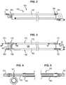
figure 2 représente une vue latérale d'un vérin de bras à glissière conforme à la présente invention équipé d'une paire de tubes télescopiques d'alimentation conforme à l'invention, - la
figure 3 représente une seconde vue latérale du même vérin de bras à glissière conforme à l'invention selon une vue orthogonale à celle de lafigure 2 montrant deux paires de tubes télescopiques d'alimentation, - les
figures 4 et 5 représentent des vues partielles en coupe longitudinale des deux extrémités du même vérin de bras à glissière conforme à l'invention selon les plans de coupe référencés respectivement IV-IV et V-V sur lafigure 3 , - les
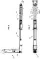
figures 6 et 7 représentent deux vues orthogonales entre elles d'un bras de levage télescopique comprenant une potence articulée en extrémité faisant application du concept de bras à glissière conforme à l'invention, - la
figure 8 illustre schématiquement un circuit hydraulique d'alimentation d'un bras à glissière conforme à la présente invention, et - les
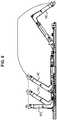
figures 9 à 12 illustrent différentes positions d'un bras à glissière conforme à l'invention, plus précisément lafigure 9 illustre différentes positions de la potence articulée, lafigure 10 représente une vue du bras en position rétractée, potence verticale, lafigure 11 représente une vue du bras télescopique étendue, potence verticale et lafigure 12 représente une vue du bras télescopique étendu, potence inclinée.
- the
figure 1 previously described schematically represents a machine according to the state of the art, - the
figure 2 represents a side view of a slide arm jack according to the present invention equipped with a pair of telescopic supply tubes according to the invention, - the
figure 3 represents a second side view of the same slide arm jack according to the invention in a view orthogonal to that of thefigure 2 showing two pairs of telescopic power tubes, - the
Figures 4 and 5 are partial views in longitudinal section of the two ends of the same slide arm jack according to the invention according to the sectional planes respectively referenced IV-IV and VV on thefigure 3 , - the
Figures 6 and 7 represent two orthogonal views between them of a telescopic lifting arm comprising an end articulated stem employing the concept of a slide arm according to the invention, - the
figure 8 schematically illustrates a hydraulic supply circuit of a slide arm according to the present invention, and - the
Figures 9 to 12 illustrate different positions of a slide arm according to the invention, more specifically thefigure 9 illustrates different positions of the articulated stem, thefigure 10 represents a view of the arm in retracted position, vertical stem, thefigure 11 represents a view of the extended telescopic arm, vertical stem and thefigure 12 represents a view of the extended telescopic arm, inclined stem.
On a représenté sur les
Par convention, l'élément 110 est situé du côté d'un châssis support, par exemple un véhicule ou engin, et l'élément 120 est susceptible de déplacement par rapport à ce châssis support sous l'actionnement d'un vérin d'extension 130.By convention, the
Le cylindre et la tige de piston du vérin d'extension 130 sont fixés respectivement sur les éléments 110, 120 du bras à glissière.The cylinder and the piston rod of the
De façon connue en soit, l'extension du vérin 130 conduit à l'extension du bras à glissière 100 et respectivement la rétractation du vérin 130 conduit à la rétractation du bras à glissière 100.In a manner known in itself, the extension of the
Comme indiqué précédemment, dans le cadre de l'invention, l'élément mobile 120 du bras à glissière 100 porte à son extrémité un équipement 140, par exemple une potence articulée comme illustré sur les
Dans le cadre de l'invention, comme indiqué précédemment, il est prévu au moins une paire 160 de tubes télescopiques 162, 165 de diamètres différents, engagés l'un dans l'autre et en liaison respective étanche quelle que soit la position relative longitudinale des tubes 162, 165. On entend par liaison étanche que le tube 165 de petit diamètre étant engagé dans le tube 162 de grand diamètre, il existe une étanchéité hydraulique entre les deux tubes 162 et 165 quelle que soit la position relative des deux tubes 162 et 165.In the context of the invention, as indicated above, there is provided at least one
Plus précisément encore, selon l'invention, il est prévu de préférence deux paires 160, 170 de tubes télescopiques 162, 165 et 172, 175 respectant la liaison respective étanche quelle que soit la position relative longitudinale des tubes.More precisely still, according to the invention, two
Selon le mode de réalisation représenté sur les figures annexées, les tubes 162, 172 sont de grand diamètre tandis que les tubes 165 et 175 sont de diamètre plus petit et sont engagés respectivement dans les tubes 162, 172.According to the embodiment shown in the accompanying figures, the
La liaison étanche entre les tubes 162, 165 et respectivement 172, 175 peut être assurée par tout moyen approprié, de préférence grâce à des joints toriques ou équivalents disposés entre la surface externe des tubes de petit diamètre 165, 175 et la surface interne des tubes 162, 172 de grand diamètre.The sealed connection between the
De tels joints toriques sont schématisés sous la référence 180 sur la
Bien entendu, ces joints 180 peuvent faire l'objet de nombreuses variantes de réalisation selon la pression de fluide mise en jeu.Of course, these
Il peut s'agir de joints à lèvres, de joints en X ou de toute autre disposition connue de l'homme de l'art et appropriée.It may be lip seals, X-joints or any other provision known to those skilled in the art and appropriate.
Les deux paires 160, 170 de tubes 162, 165 et 172, 175 sont disposées parallèlement à l'axe longitudinal du vérin d'extension 130 et par conséquent également parallèlement à la direction d'élongation des éléments 110, 120 du bras à glissière et sont fixés respectivement sur le cylindre et sur la tige de piston du vérin d'extension 130.The two
La fixation des tubes 162, 172 sur le cylindre du vérin d'extension 130 et la fixation des tubes 165, 175 sur la tige de piston du vérin d'extension 130, sont assurées par tout moyen approprié, par exemple par l'intermédiaire de platines 166, 167 dimensionnées pour reprendre les efforts.Fixing the
Les extrémités amonts 161, 171 des tubes 162, 172 sont reliées à des moyens d'alimentation qui seront décrits par la suite en regard de la
Les extrémités avals 163, 173 des tubes avals 165, 175 sont elles reliées aux chambres 152, 154 respectives du vérin embarqué 150.The downstream ends 163, 173 of the
La longueur cumulée des deux tubes 162, 165 et respectivement 172, 175 doit être au moins égale à la longueur maximale en extension du bras à glissière 100. La longueur de superposition des deux tubes 162, 165 et respectivement 172, 175 doit être au moins égale à la course du bras à glissière 100 entre ses positions respectivement rétractée et étendue.The cumulative length of the two
Les tubes 162, 165 et 172, 175 sont dimensionnés afin de résister à la pression d'alimentation et à éviter tout risque de flambage.The
On va maintenant décrire le circuit d'alimentation illustré sur la
Sur cette figure, on aperçoit un réservoir d'huile 200 et une pompe 210 qui pompe de l'huile dans le réservoir 200.In this figure, there is an
Un distributeur 220, par exemple quatre voies, trois positions, permet de diriger sélectivement l'huile débitée par la pompe 210 vers le vérin d'extension 130.A
Plus précisément, une entrée 221 du distributeur 220 est reliée par l'intermédiaire d'un clapet anti-retour 230 à la sortie de la pompe 210.More specifically, an
Une seconde entrée 222 du distributeur 220 est reliée à un conduit de retour 232 qui débouche dans le réservoir 200 par l'intermédiaire d'un filtre 234.A
Les deux sorties 223, 224 du distributeur 220 sont reliées respectivement aux chambres 132, 134 disposées respectivement de part et d'autre du piston 131 du vérin d'extension 130.The two
En position de repos illustrée sur la
Dans une première position de travail, le distributeur 220 assure la liaison de l'entrée 221 sur la sortie 223 et la liaison de l'entrée 222 sur la sortie 224 provoquant l'alimentation de la chambre 132 et par conséquent l'extension du vérin 130.In a first working position, the
Inversement dans la deuxième position de travail, le distributeur 220 assure l'alimentation croisée de la sortie 224 par l'entrée 221 et de la sortie 223 par l'entrée 222 assurant ainsi l'alimentation de la chambre opposée 134 du vérin 130 et par conséquent sa rétractation.Conversely, in the second working position, the
On aperçoit en outre sur la
Le distributeur 240 est typiquement du type quatre voies, trois positions.The
En position de repos illustré sur la
Les deux sorties 243, 244 reliées par ailleurs aux extrémités amont 161, 171 des tubes d'alimentation 162, 172 sont reliées au réservoir 200.The two
Dans une première position de travail, le distributeur 240 assure la liaison de la première entrée 241 avec la première sortie 243 et la liaison de la deuxième entrée 242 avec la deuxième sortie 244 pour assurer l'alimentation de la chambre de rétractation 154 du vérin 150.In a first working position, the
Inversement, dans la seconde position de travail, le distributeur 240 assure la liaison croisée de l'entrée 241 avec la sortie 244 et de l'entrée 242 avec la sortie 243.Conversely, in the second working position, the
Dans cette deuxième position de travail, la deuxième chambre 152 est alimentée en huile sous pression pour assurer l'extension du vérin actionnant l'équipement 140.In this second working position, the
La première entrée 241 est reliée à la sortie de la pompe 210 par l'intermédiaire d'un clapet anti-retour 236.The
La deuxième entrée 242 du distributeur 240 est reliée au réservoir 200 par l'intermédiaire du filtre 234.The
On notera que de préférence, le circuit d'alimentation comprend également des moyens permettant de moduler le débit fourni par la pompe 210 au vérin 150 afin de définir deux vitesses d'actionnement.It will be noted that, preferably, the supply circuit also comprises means making it possible to modulate the flow rate supplied by the
De tels moyens peuvent être formés par exemple par une restriction 238 placée entre la sortie de la pompe 210 et le clapet anti-retour 236 pour définir un faible débit d'huile et par conséquent une faible vitesse d'actionnement du vérin 250 et un distributeur 239 formant clapet tout ou rien placé en parallèle de la restriction 238.Such means may be formed for example by a
En position ouverte du clapet 239, la restriction 238 est court-circuitée et un débit fort peut être adressé au vérin 250.In the open position of the
En position fermée du clapet 239, le fluide dirigé vers le vérin 150 passe par la restriction 238.In the closed position of the
Lorsque le bras à glissière 100 bouge sous la commande du vérin d'extension 130, plus précisément l'élément 120 est déplacé par rapport à l'élément 110, le système d'alimentation constitué par les paires 160, 170 de tubes 162, 165 et 172, 175 suit le mouvement.When the
Le distributeur 240 est placé automatiquement en position médiane en centre ouvert lorsque le vérin d'extension 130 est commandé en extension/rétractation. Ainsi la position centre ouvert du distributeur 240 permet d'éviter tout risque d'éclatement des tubes 162, 165 et 172, 175.The
De préférence, le circuit d'alimentation est contrôlé de sorte que le mouvement du vérin alimenté 150 n'est autorisé que lorsque le vérin d'extension 130 est immobile.Preferably, the supply circuit is controlled so that the movement of the
Le système conforme à l'invention est compact et peut être intégré facilement sur le bras à glissière 100.The system according to the invention is compact and can be easily integrated on the
Les
Claims (10)
Translated fromFrenchApplications Claiming Priority (1)
| Application Number | Priority Date | Filing Date | Title |
|---|---|---|---|
| FR1760582AFR3073584B1 (en) | 2017-11-10 | 2017-11-10 | TELESCOPIC SYSTEM COMPRISING AT THE END A JACK ACTUATED EQUIPMENT |
Publications (2)
| Publication Number | Publication Date |
|---|---|
| EP3483111A1true EP3483111A1 (en) | 2019-05-15 |
| EP3483111B1 EP3483111B1 (en) | 2022-11-30 |
Family
ID=61003181
Family Applications (1)
| Application Number | Title | Priority Date | Filing Date |
|---|---|---|---|
| EP18205077.3AActiveEP3483111B1 (en) | 2017-11-10 | 2018-11-08 | Telescopic system comprising end equipment activated by an actuator |
Country Status (5)
| Country | Link |
|---|---|
| EP (1) | EP3483111B1 (en) |
| ES (1) | ES2935485T3 (en) |
| FI (1) | FI3483111T3 (en) |
| FR (1) | FR3073584B1 (en) |
| PL (1) | PL3483111T3 (en) |
Cited By (2)
| Publication number | Priority date | Publication date | Assignee | Title |
|---|---|---|---|---|
| US20220341323A1 (en)* | 2019-08-26 | 2022-10-27 | Epiroc Rock Drills Aktiebolag | A mining machine and a method for rock excavation |
| IT202200018219A1 (en)* | 2022-09-07 | 2024-03-07 | Oleodinamica Panni S R L | DEVICE FOR POWERING AND MOVING A HYDRAULIC TOOL, SYSTEM AND VEHICLE |
Citations (4)
| Publication number | Priority date | Publication date | Assignee | Title |
|---|---|---|---|---|
| NL9301464A (en)* | 1993-08-24 | 1995-03-16 | Ruiter Verenigde Bedrijven B V | Telescopic arm |
| US5769251A (en)* | 1993-11-08 | 1998-06-23 | Komatsu Ltd. | Controlling operations of a reach tower crane |
| EP2520530A1 (en)* | 2011-05-06 | 2012-11-07 | B.O.B. Sistemi Idraulici S.p.A. | Telescopic arm for a crane moving an attachment member |
| EP2568084A1 (en)* | 2011-09-07 | 2013-03-13 | EPSILON Kran GmbH. | Telescopic crane arm |
- 2017
- 2017-11-10FRFR1760582Apatent/FR3073584B1/ennot_activeExpired - Fee Related
- 2018
- 2018-11-08ESES18205077Tpatent/ES2935485T3/enactiveActive
- 2018-11-08PLPL18205077.3Tpatent/PL3483111T3/enunknown
- 2018-11-08EPEP18205077.3Apatent/EP3483111B1/enactiveActive
- 2018-11-08FIFIEP18205077.3Tpatent/FI3483111T3/enactive
Patent Citations (4)
| Publication number | Priority date | Publication date | Assignee | Title |
|---|---|---|---|---|
| NL9301464A (en)* | 1993-08-24 | 1995-03-16 | Ruiter Verenigde Bedrijven B V | Telescopic arm |
| US5769251A (en)* | 1993-11-08 | 1998-06-23 | Komatsu Ltd. | Controlling operations of a reach tower crane |
| EP2520530A1 (en)* | 2011-05-06 | 2012-11-07 | B.O.B. Sistemi Idraulici S.p.A. | Telescopic arm for a crane moving an attachment member |
| EP2568084A1 (en)* | 2011-09-07 | 2013-03-13 | EPSILON Kran GmbH. | Telescopic crane arm |
Cited By (2)
| Publication number | Priority date | Publication date | Assignee | Title |
|---|---|---|---|---|
| US20220341323A1 (en)* | 2019-08-26 | 2022-10-27 | Epiroc Rock Drills Aktiebolag | A mining machine and a method for rock excavation |
| IT202200018219A1 (en)* | 2022-09-07 | 2024-03-07 | Oleodinamica Panni S R L | DEVICE FOR POWERING AND MOVING A HYDRAULIC TOOL, SYSTEM AND VEHICLE |
Also Published As
| Publication number | Publication date |
|---|---|
| FR3073584A1 (en) | 2019-05-17 |
| EP3483111B1 (en) | 2022-11-30 |
| PL3483111T3 (en) | 2023-03-13 |
| ES2935485T3 (en) | 2023-03-07 |
| FR3073584B1 (en) | 2020-07-03 |
| FI3483111T3 (en) | 2023-02-28 |
Similar Documents
| Publication | Publication Date | Title |
|---|---|---|
| EP3483111B1 (en) | Telescopic system comprising end equipment activated by an actuator | |
| FR2501127A1 (en) | BEARING SYSTEM STRUCTURE FOR CONSTRUCTION EQUIPMENT | |
| EP0624225A1 (en) | Multi-arm stabilizer for a drilling or boring device. | |
| EP3221193B1 (en) | Method of supplying a hydraulic motor for a drive wheel with hydraulic fluid, associated cylinder-type suspension system and vehicle equipped therewith | |
| FR2537184A1 (en) | HYDRAULIC PROCESS AND CIRCUIT FOR SAVING ENERGY WHEN OPERATING A MANEUVERING CYLINDER ON A HYDRAULIC EXCAVATOR | |
| EP0370865B1 (en) | Landing gear orientation device | |
| FR2735813A1 (en) | ASSEMBLY FOR AN ADVANCE TELESCOPIC MEMBER FOR A ROCK DRILLING MACHINE | |
| FR3096097B1 (en) | Hydraulic cylinder equipped with an end-of-stroke slowing device | |
| FR2616489A1 (en) | MULTIPLE CYLINDER WITH AT LEAST THREE SLIDING ELEMENTS AND TELESCOPIC ARROW BY APPLYING | |
| FR2670716A1 (en) | Safety device mounted on an active anti-roll hydraulic cylinder | |
| FR2634817A1 (en) | DEVICE FOR CONTROLLING HYDRAULIC ACTUATING MEANS IN A ROCK DRILLING ARROW AND AN ANALOGUE ARRAY STRUCTURE | |
| EP0776426B1 (en) | Hydraulic control device for a double acting cylinder | |
| FR2549437A1 (en) | Hydraulic two-stage steering for vehicle | |
| EP1679282B1 (en) | Crane with balanced jib and auxiliary jib which can be maintained vertical | |
| US3680713A (en) | Fluid power device | |
| EP4178903B1 (en) | Load-handling vehicle | |
| FR2938401A1 (en) | AGRICULTURAL MACHINE INTENDED TO BE REPORTED ON A TRACTOR AND COMPRISING A LIFTING JACK AND A DELINTATING JACK OF A WORKING UNIT | |
| EP2872784B1 (en) | Device for controlling the movement of a hydraulic cylinder, particularly for hydraulic machines | |
| FR2731729A1 (en) | Hydraulic control circuit for loading arms on tractors | |
| FR2916411A1 (en) | BIDIRECTIONAL GUIDE SYSTEM WITH LATERAL DEBATMENT LIMITATION, FOR A ROAD AXIAL GUIDED BY A GROUND RAIL. | |
| FR2698930A1 (en) | Hydraulically operated brake control for tractor or tracked vehicles - includes two concentrically disposed jacks whose bodies define variable volume pressure chamber between them, with body of internal jack forming piston of external jack | |
| CA3183467A1 (en) | Landing gear locking device | |
| FR2591158A1 (en) | Method for supplying hydraulic fluid to a user device, installation for the purpose of implementing this method and equipment provided with this installation | |
| EP0823370A1 (en) | Actuating device for the locking cylinder of a suspension arm of a vehicle | |
| FR2614370A1 (en) | Machine raising the pressure of a pressurised gas without the supply of outside energy |
Legal Events
| Date | Code | Title | Description |
|---|---|---|---|
| PUAI | Public reference made under article 153(3) epc to a published international application that has entered the european phase | Free format text:ORIGINAL CODE: 0009012 | |
| STAA | Information on the status of an ep patent application or granted ep patent | Free format text:STATUS: REQUEST FOR EXAMINATION WAS MADE | |
| 17P | Request for examination filed | Effective date:20181108 | |
| AK | Designated contracting states | Kind code of ref document:A1 Designated state(s):AL AT BE BG CH CY CZ DE DK EE ES FI FR GB GR HR HU IE IS IT LI LT LU LV MC MK MT NL NO PL PT RO RS SE SI SK SM TR | |
| AX | Request for extension of the european patent | Extension state:BA ME | |
| GRAP | Despatch of communication of intention to grant a patent | Free format text:ORIGINAL CODE: EPIDOSNIGR1 | |
| STAA | Information on the status of an ep patent application or granted ep patent | Free format text:STATUS: GRANT OF PATENT IS INTENDED | |
| RIC1 | Information provided on ipc code assigned before grant | Ipc:B60P 1/54 20060101ALI20220601BHEP Ipc:B66C 13/12 20060101ALI20220601BHEP Ipc:F15B 15/14 20060101ALI20220601BHEP Ipc:B66C 23/70 20060101AFI20220601BHEP | |
| INTG | Intention to grant announced | Effective date:20220627 | |
| GRAS | Grant fee paid | Free format text:ORIGINAL CODE: EPIDOSNIGR3 | |
| GRAA | (expected) grant | Free format text:ORIGINAL CODE: 0009210 | |
| STAA | Information on the status of an ep patent application or granted ep patent | Free format text:STATUS: THE PATENT HAS BEEN GRANTED | |
| AK | Designated contracting states | Kind code of ref document:B1 Designated state(s):AL AT BE BG CH CY CZ DE DK EE ES FI FR GB GR HR HU IE IS IT LI LT LU LV MC MK MT NL NO PL PT RO RS SE SI SK SM TR | |
| REG | Reference to a national code | Ref country code:CH Ref legal event code:EP Ref country code:GB Ref legal event code:FG4D Free format text:NOT ENGLISH | |
| REG | Reference to a national code | Ref country code:AT Ref legal event code:REF Ref document number:1534561 Country of ref document:AT Kind code of ref document:T Effective date:20221215 | |
| REG | Reference to a national code | Ref country code:IE Ref legal event code:FG4D Free format text:LANGUAGE OF EP DOCUMENT: FRENCH | |
| REG | Reference to a national code | Ref country code:DE Ref legal event code:R096 Ref document number:602018043590 Country of ref document:DE | |
| REG | Reference to a national code | Ref country code:NL Ref legal event code:FP | |
| REG | Reference to a national code | Ref country code:SE Ref legal event code:TRGR | |
| REG | Reference to a national code | Ref country code:ES Ref legal event code:FG2A Ref document number:2935485 Country of ref document:ES Kind code of ref document:T3 Effective date:20230307 | |
| REG | Reference to a national code | Ref country code:LT Ref legal event code:MG9D | |
| PG25 | Lapsed in a contracting state [announced via postgrant information from national office to epo] | Ref country code:PT Free format text:LAPSE BECAUSE OF FAILURE TO SUBMIT A TRANSLATION OF THE DESCRIPTION OR TO PAY THE FEE WITHIN THE PRESCRIBED TIME-LIMIT Effective date:20230331 Ref country code:NO Free format text:LAPSE BECAUSE OF FAILURE TO SUBMIT A TRANSLATION OF THE DESCRIPTION OR TO PAY THE FEE WITHIN THE PRESCRIBED TIME-LIMIT Effective date:20230228 Ref country code:LT Free format text:LAPSE BECAUSE OF FAILURE TO SUBMIT A TRANSLATION OF THE DESCRIPTION OR TO PAY THE FEE WITHIN THE PRESCRIBED TIME-LIMIT Effective date:20221130 | |
| PG25 | Lapsed in a contracting state [announced via postgrant information from national office to epo] | Ref country code:RS Free format text:LAPSE BECAUSE OF FAILURE TO SUBMIT A TRANSLATION OF THE DESCRIPTION OR TO PAY THE FEE WITHIN THE PRESCRIBED TIME-LIMIT Effective date:20221130 Ref country code:LV Free format text:LAPSE BECAUSE OF FAILURE TO SUBMIT A TRANSLATION OF THE DESCRIPTION OR TO PAY THE FEE WITHIN THE PRESCRIBED TIME-LIMIT Effective date:20221130 Ref country code:IS Free format text:LAPSE BECAUSE OF FAILURE TO SUBMIT A TRANSLATION OF THE DESCRIPTION OR TO PAY THE FEE WITHIN THE PRESCRIBED TIME-LIMIT Effective date:20230330 Ref country code:HR Free format text:LAPSE BECAUSE OF FAILURE TO SUBMIT A TRANSLATION OF THE DESCRIPTION OR TO PAY THE FEE WITHIN THE PRESCRIBED TIME-LIMIT Effective date:20221130 Ref country code:GR Free format text:LAPSE BECAUSE OF FAILURE TO SUBMIT A TRANSLATION OF THE DESCRIPTION OR TO PAY THE FEE WITHIN THE PRESCRIBED TIME-LIMIT Effective date:20230301 | |
| PG25 | Lapsed in a contracting state [announced via postgrant information from national office to epo] | Ref country code:SM Free format text:LAPSE BECAUSE OF FAILURE TO SUBMIT A TRANSLATION OF THE DESCRIPTION OR TO PAY THE FEE WITHIN THE PRESCRIBED TIME-LIMIT Effective date:20221130 Ref country code:RO Free format text:LAPSE BECAUSE OF FAILURE TO SUBMIT A TRANSLATION OF THE DESCRIPTION OR TO PAY THE FEE WITHIN THE PRESCRIBED TIME-LIMIT Effective date:20221130 Ref country code:EE Free format text:LAPSE BECAUSE OF FAILURE TO SUBMIT A TRANSLATION OF THE DESCRIPTION OR TO PAY THE FEE WITHIN THE PRESCRIBED TIME-LIMIT Effective date:20221130 Ref country code:DK Free format text:LAPSE BECAUSE OF FAILURE TO SUBMIT A TRANSLATION OF THE DESCRIPTION OR TO PAY THE FEE WITHIN THE PRESCRIBED TIME-LIMIT Effective date:20221130 | |
| PG25 | Lapsed in a contracting state [announced via postgrant information from national office to epo] | Ref country code:SK Free format text:LAPSE BECAUSE OF FAILURE TO SUBMIT A TRANSLATION OF THE DESCRIPTION OR TO PAY THE FEE WITHIN THE PRESCRIBED TIME-LIMIT Effective date:20221130 Ref country code:AL Free format text:LAPSE BECAUSE OF FAILURE TO SUBMIT A TRANSLATION OF THE DESCRIPTION OR TO PAY THE FEE WITHIN THE PRESCRIBED TIME-LIMIT Effective date:20221130 | |
| REG | Reference to a national code | Ref country code:DE Ref legal event code:R097 Ref document number:602018043590 Country of ref document:DE | |
| PLBE | No opposition filed within time limit | Free format text:ORIGINAL CODE: 0009261 | |
| STAA | Information on the status of an ep patent application or granted ep patent | Free format text:STATUS: NO OPPOSITION FILED WITHIN TIME LIMIT | |
| 26N | No opposition filed | Effective date:20230831 | |
| PG25 | Lapsed in a contracting state [announced via postgrant information from national office to epo] | Ref country code:SI Free format text:LAPSE BECAUSE OF FAILURE TO SUBMIT A TRANSLATION OF THE DESCRIPTION OR TO PAY THE FEE WITHIN THE PRESCRIBED TIME-LIMIT Effective date:20221130 | |
| REG | Reference to a national code | Ref country code:AT Ref legal event code:UEP Ref document number:1534561 Country of ref document:AT Kind code of ref document:T Effective date:20221130 | |
| PG25 | Lapsed in a contracting state [announced via postgrant information from national office to epo] | Ref country code:MC Free format text:LAPSE BECAUSE OF FAILURE TO SUBMIT A TRANSLATION OF THE DESCRIPTION OR TO PAY THE FEE WITHIN THE PRESCRIBED TIME-LIMIT Effective date:20221130 | |
| PG25 | Lapsed in a contracting state [announced via postgrant information from national office to epo] | Ref country code:LU Free format text:LAPSE BECAUSE OF NON-PAYMENT OF DUE FEES Effective date:20231108 | |
| GBPC | Gb: european patent ceased through non-payment of renewal fee | Effective date:20231108 | |
| PG25 | Lapsed in a contracting state [announced via postgrant information from national office to epo] | Ref country code:MC Free format text:LAPSE BECAUSE OF FAILURE TO SUBMIT A TRANSLATION OF THE DESCRIPTION OR TO PAY THE FEE WITHIN THE PRESCRIBED TIME-LIMIT Effective date:20221130 Ref country code:LU Free format text:LAPSE BECAUSE OF NON-PAYMENT OF DUE FEES Effective date:20231108 | |
| REG | Reference to a national code | Ref country code:IE Ref legal event code:MM4A | |
| PG25 | Lapsed in a contracting state [announced via postgrant information from national office to epo] | Ref country code:IE Free format text:LAPSE BECAUSE OF NON-PAYMENT OF DUE FEES Effective date:20231108 | |
| PG25 | Lapsed in a contracting state [announced via postgrant information from national office to epo] | Ref country code:GB Free format text:LAPSE BECAUSE OF NON-PAYMENT OF DUE FEES Effective date:20231108 | |
| PG25 | Lapsed in a contracting state [announced via postgrant information from national office to epo] | Ref country code:IE Free format text:LAPSE BECAUSE OF NON-PAYMENT OF DUE FEES Effective date:20231108 Ref country code:GB Free format text:LAPSE BECAUSE OF NON-PAYMENT OF DUE FEES Effective date:20231108 | |
| PG25 | Lapsed in a contracting state [announced via postgrant information from national office to epo] | Ref country code:BG Free format text:LAPSE BECAUSE OF FAILURE TO SUBMIT A TRANSLATION OF THE DESCRIPTION OR TO PAY THE FEE WITHIN THE PRESCRIBED TIME-LIMIT Effective date:20221130 | |
| PGFP | Annual fee paid to national office [announced via postgrant information from national office to epo] | Ref country code:NL Payment date:20241029 Year of fee payment:7 | |
| PG25 | Lapsed in a contracting state [announced via postgrant information from national office to epo] | Ref country code:BG Free format text:LAPSE BECAUSE OF FAILURE TO SUBMIT A TRANSLATION OF THE DESCRIPTION OR TO PAY THE FEE WITHIN THE PRESCRIBED TIME-LIMIT Effective date:20221130 | |
| PGFP | Annual fee paid to national office [announced via postgrant information from national office to epo] | Ref country code:DE Payment date:20241108 Year of fee payment:7 | |
| PGFP | Annual fee paid to national office [announced via postgrant information from national office to epo] | Ref country code:BE Payment date:20241113 Year of fee payment:7 Ref country code:PL Payment date:20241021 Year of fee payment:7 Ref country code:FI Payment date:20241023 Year of fee payment:7 | |
| PGFP | Annual fee paid to national office [announced via postgrant information from national office to epo] | Ref country code:FR Payment date:20241011 Year of fee payment:7 Ref country code:AT Payment date:20241023 Year of fee payment:7 | |
| PGFP | Annual fee paid to national office [announced via postgrant information from national office to epo] | Ref country code:CZ Payment date:20241104 Year of fee payment:7 | |
| PGFP | Annual fee paid to national office [announced via postgrant information from national office to epo] | Ref country code:IT Payment date:20241108 Year of fee payment:7 Ref country code:ES Payment date:20241209 Year of fee payment:7 | |
| PGFP | Annual fee paid to national office [announced via postgrant information from national office to epo] | Ref country code:SE Payment date:20241125 Year of fee payment:7 | |
| PGFP | Annual fee paid to national office [announced via postgrant information from national office to epo] | Ref country code:CH Payment date:20241201 Year of fee payment:7 | |
| PG25 | Lapsed in a contracting state [announced via postgrant information from national office to epo] | Ref country code:CY Free format text:LAPSE BECAUSE OF FAILURE TO SUBMIT A TRANSLATION OF THE DESCRIPTION OR TO PAY THE FEE WITHIN THE PRESCRIBED TIME-LIMIT; INVALID AB INITIO Effective date:20181108 | |
| PG25 | Lapsed in a contracting state [announced via postgrant information from national office to epo] | Ref country code:HU Free format text:LAPSE BECAUSE OF FAILURE TO SUBMIT A TRANSLATION OF THE DESCRIPTION OR TO PAY THE FEE WITHIN THE PRESCRIBED TIME-LIMIT; INVALID AB INITIO Effective date:20181108 |