EP3482243B1 - Polarity changeable connector - Google Patents
Polarity changeable connectorDownload PDFInfo
- Publication number
- EP3482243B1 EP3482243B1EP17824733.4AEP17824733AEP3482243B1EP 3482243 B1EP3482243 B1EP 3482243B1EP 17824733 AEP17824733 AEP 17824733AEP 3482243 B1EP3482243 B1EP 3482243B1
- Authority
- EP
- European Patent Office
- Prior art keywords
- inner housing
- key
- connector
- optical fiber
- housing
- Prior art date
- Legal status (The legal status is an assumption and is not a legal conclusion. Google has not performed a legal analysis and makes no representation as to the accuracy of the status listed.)
- Active
Links
Images


Classifications
- G—PHYSICS
- G02—OPTICS
- G02B—OPTICAL ELEMENTS, SYSTEMS OR APPARATUS
- G02B6/00—Light guides; Structural details of arrangements comprising light guides and other optical elements, e.g. couplings
- G02B6/24—Coupling light guides
- G02B6/36—Mechanical coupling means
- G02B6/38—Mechanical coupling means having fibre to fibre mating means
- G02B6/3807—Dismountable connectors, i.e. comprising plugs
- G02B6/381—Dismountable connectors, i.e. comprising plugs of the ferrule type, e.g. fibre ends embedded in ferrules, connecting a pair of fibres
- G02B6/3826—Dismountable connectors, i.e. comprising plugs of the ferrule type, e.g. fibre ends embedded in ferrules, connecting a pair of fibres characterised by form or shape
- G02B6/3831—Dismountable connectors, i.e. comprising plugs of the ferrule type, e.g. fibre ends embedded in ferrules, connecting a pair of fibres characterised by form or shape comprising a keying element on the plug or adapter, e.g. to forbid wrong connection
- G—PHYSICS
- G02—OPTICS
- G02B—OPTICAL ELEMENTS, SYSTEMS OR APPARATUS
- G02B6/00—Light guides; Structural details of arrangements comprising light guides and other optical elements, e.g. couplings
- G02B6/24—Coupling light guides
- G02B6/36—Mechanical coupling means
- G02B6/38—Mechanical coupling means having fibre to fibre mating means
- G02B6/3807—Dismountable connectors, i.e. comprising plugs
- G—PHYSICS
- G02—OPTICS
- G02B—OPTICAL ELEMENTS, SYSTEMS OR APPARATUS
- G02B6/00—Light guides; Structural details of arrangements comprising light guides and other optical elements, e.g. couplings
- G—PHYSICS
- G02—OPTICS
- G02B—OPTICAL ELEMENTS, SYSTEMS OR APPARATUS
- G02B6/00—Light guides; Structural details of arrangements comprising light guides and other optical elements, e.g. couplings
- G02B6/24—Coupling light guides
- G02B6/36—Mechanical coupling means
- G02B6/38—Mechanical coupling means having fibre to fibre mating means
- G02B6/3807—Dismountable connectors, i.e. comprising plugs
- G02B6/381—Dismountable connectors, i.e. comprising plugs of the ferrule type, e.g. fibre ends embedded in ferrules, connecting a pair of fibres
- G02B6/3812—Dismountable connectors, i.e. comprising plugs of the ferrule type, e.g. fibre ends embedded in ferrules, connecting a pair of fibres having polarisation-maintaining light guides
- G—PHYSICS
- G02—OPTICS
- G02B—OPTICAL ELEMENTS, SYSTEMS OR APPARATUS
- G02B6/00—Light guides; Structural details of arrangements comprising light guides and other optical elements, e.g. couplings
- G02B6/24—Coupling light guides
- G02B6/36—Mechanical coupling means
- G02B6/38—Mechanical coupling means having fibre to fibre mating means
- G02B6/3807—Dismountable connectors, i.e. comprising plugs
- G02B6/381—Dismountable connectors, i.e. comprising plugs of the ferrule type, e.g. fibre ends embedded in ferrules, connecting a pair of fibres
- G02B6/3825—Dismountable connectors, i.e. comprising plugs of the ferrule type, e.g. fibre ends embedded in ferrules, connecting a pair of fibres with an intermediate part, e.g. adapter, receptacle, linking two plugs
- G—PHYSICS
- G02—OPTICS
- G02B—OPTICAL ELEMENTS, SYSTEMS OR APPARATUS
- G02B6/00—Light guides; Structural details of arrangements comprising light guides and other optical elements, e.g. couplings
- G02B6/24—Coupling light guides
- G02B6/36—Mechanical coupling means
- G02B6/38—Mechanical coupling means having fibre to fibre mating means
- G02B6/3807—Dismountable connectors, i.e. comprising plugs
- G02B6/3869—Mounting ferrules to connector body, i.e. plugs
- G02B6/387—Connector plugs comprising two complementary members, e.g. shells, caps, covers, locked together
- G—PHYSICS
- G02—OPTICS
- G02B—OPTICAL ELEMENTS, SYSTEMS OR APPARATUS
- G02B6/00—Light guides; Structural details of arrangements comprising light guides and other optical elements, e.g. couplings
- G02B6/24—Coupling light guides
- G02B6/36—Mechanical coupling means
- G02B6/38—Mechanical coupling means having fibre to fibre mating means
- G02B6/3807—Dismountable connectors, i.e. comprising plugs
- G02B6/3869—Mounting ferrules to connector body, i.e. plugs
- G02B6/3871—Ferrule rotatable with respect to plug body, e.g. for setting rotational position ; Fixation of ferrules after rotation
- G—PHYSICS
- G02—OPTICS
- G02B—OPTICAL ELEMENTS, SYSTEMS OR APPARATUS
- G02B6/00—Light guides; Structural details of arrangements comprising light guides and other optical elements, e.g. couplings
- G02B6/24—Coupling light guides
- G02B6/36—Mechanical coupling means
- G02B6/38—Mechanical coupling means having fibre to fibre mating means
- G02B6/3807—Dismountable connectors, i.e. comprising plugs
- G02B6/3873—Connectors using guide surfaces for aligning ferrule ends, e.g. tubes, sleeves, V-grooves, rods, pins, balls
- G02B6/3885—Multicore or multichannel optical connectors, i.e. one single ferrule containing more than one fibre, e.g. ribbon type
- G—PHYSICS
- G02—OPTICS
- G02B—OPTICAL ELEMENTS, SYSTEMS OR APPARATUS
- G02B6/00—Light guides; Structural details of arrangements comprising light guides and other optical elements, e.g. couplings
- G02B6/24—Coupling light guides
- G02B6/36—Mechanical coupling means
- G02B6/38—Mechanical coupling means having fibre to fibre mating means
- G02B6/3807—Dismountable connectors, i.e. comprising plugs
- G02B6/389—Dismountable connectors, i.e. comprising plugs characterised by the method of fastening connecting plugs and sockets, e.g. screw- or nut-lock, snap-in, bayonet type
- G02B6/3893—Push-pull type, e.g. snap-in, push-on
Definitions
- optical fibersare extremely small. For example, even with protective coatings, optical fibers may be only about 250 microns in diameter (only about 4 times the diameter of a human hair). As such, hundreds of fibers can be installed in cables that will take up relatively little space. For connections between cables, however, the fibers are terminated with connectors. Multiple fibers may be arranged within a single connector.
- multi-fiber connectorssuch as those using multi-fiber push-on/pull-off (MPO) technology may contain and connect 12 or 24 fibers.
- Connectorssuch as MPO type connectors, generally include a housing portion that contains a ferrule that terminates the ends of the fibers. Ferrules are generally used to retain the ends of the optical fibers for connecting the optical fibers.
- MPO type connectorsgenerally include a housing portion that contains a ferrule that terminates the ends of the fibers. Ferrules are generally used to retain the ends of the optical fibers for connecting the optical fibers.
- MTMechanismically Transferable
- MPO connectorsare joined together to connect the optical transmission path of one fiber optic cable to another fiber optic cable or device, and the connection may be made by inserting the MPO connectors in an MPO adapter.
- An adaptergenerally includes a housing, or portion of a housing, having at least one port which is configured to receive and hold a connector to facilitate the optical connection of the connector ferrule with the ferrule of another connector or other device.
- Adaptersmay be used to facilitate connections contained within a chassis.
- chassisas used herein broadly refers to a containment structure for housing electrical components or switching components.
- polaritymaintains proper continuity between transmitters and receivers.
- the connector and adapterIn order to make sure that connectors are mated correctly with an adapter, the connector and adapter typically include fixed keying features that permit the connector to be mated with the adapter in generally only one mating configuration. While this has the advantage of preventing a connection that has the wrong polarity, it also can make it difficult to change the polarity of the connection on site.
- optical fiber connectoraccording to claim 1 or 2.
- Preferred embodiments of the inventionare disclosed in the dependent claims.
- an optical fiber connectorcomprises a ferrule, and an inner housing disposed around at least a portion of the ferrule, the housing comprising a first end for being inserted into an optical fiber adapter, and a second end disposed opposite the first end.
- the connectorfurther comprises at least one key configured to move along the inner housing so as to change a polarity of said optical fiber connector with respect to the adapter.
- the connectorfurther comprises an outer housing disposed around at least a portion of the inner housing and configured to slide in a longitudinal direction towards the second end so as to expose at least a portion of said at least one key, wherein the outer housing includes a flexible portion configured to lock to the second end of the inner housing so as to retain the outer housing in a pulled position at the second end of the inner housing.
- the flexible portionmay be configured to engage a mating portion at the second end of the inner housing.
- the flexible portionmay comprise an opening and the mating portion may comprise a protruding portion configured to engage the opening when the flexible portion is pushed towards the second end.
- the openingmay have a circular shape.
- the connectorcomprises at least one biasing member for biasing the outer housing towards the first end of the inner housing.
- the connectormay be an MPO connector.
- the flexible portionmay comprise a flat surface.
- the at least one keymay include a surface having a draft angle.
- the inner housingmay include a corresponding surface having a corresponding draft angle and configured to retain the at least one key.
- the draft anglemay be about three degrees.
- a housing of the connectormay be configured to include a removable key that may be positioned at alternate locations on the housing.
- the keymay be moved from one location to another.
- changing the polarityrequires a user to slide back and hold back an outer housing of the connector, push a key in or pull it out on one side of the housing, and do the reverse, that is pull the key out or push it in on the opposite side of the housing.
- this processideally requires "three hands,” and may be facilitated in various embodiments disclosed herein, by providing a lockable outer housing of the connector, so as to allow a user to use both hands to move the key.
- Various embodimentsprovide multi-fiber, fiber optic connectors, such as an MPO connector, having an outer housing configured to be pulled back from the main body or inner housing, then squeezed to lock it, so that the outer housing will not push back to its original position. This allows users to change the position of the key without having to hold back the outer housing, thereby reducing the complexity of the operation needed to change the connector's polarity.
- the keymay be configured such that it does not slide out of the connector easily.
- the keymay be configured to include a surface having a draft angle instead of a flat surface.
- the main body or inner housing of the connectormay include a corresponding surface having a draft angle and configured to engage the key.
- the draft anglemay be about 3 degrees. The draft angle prevents the key from easily coming out or slipping out of the connector.
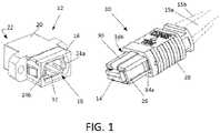
- Adapters 12may be configured to be mounted on a chassis panel, and may include mounting flanges 26a, 26b to mount the adapter via screws, for example.
- a connector 10may include an inner housing 26 that may surround the ferrule 14.
- ferrule 14is of the female type - a pairing connector may have a male-type ferrule with two guide pins that fit into the receiving holes of the female ferrule.
- a connector 10may also include an outer housing 28 that may be slidably disposed about the inner housing 26 adjacent the second end of the connector 10.
- the inner housingmay include an alignment key 30 that is configured to fit within keying slot 32 of the adapter. For example, in the embodiment depicted, one of the connector 10 or adapter 12 will need to be rotated about its axis 180° to align the key 30 with the slot 32.
- Inner housing 26may slide into port 18 until tabs 24a, 24b engage into slots 34a, 34b of the inner housing.
- the outer housing 28may be moved towards the second end to allow the tabs 24a, 24b to engage into slots 34a, 34b, and to retain the tabs in the slots, the outer housing may be slid back towards the first end and over the tabs.
- the outer housing 28may be biased towards the first end via springs or alternative types of biasing devices.
- the key position of the key 30 of connector 10bwould need to be changed to the opposite surface for reversed alignment in an adapter 12, fiber No. 1 of the connector 10a may mate with fiber No. 12 of connector 10b , and similarly, fiber No. 12 of the connector 10a may mate with fiber No. 1 of the connector 10b.
- the key 30 of the connector 10acould be changed, or in a further embodiment, a different type of adapter may be used, wherein the slots 32 may be aligned on the same internal surface within the adapter 12.
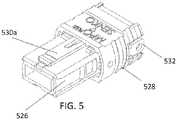
- FIG. 5is perspective view of an optical fiber connector having a lockable outer housing 528 according to aspects of the present disclosure.
- the lockable housing 528is configured to slide over the inner housing 526. Moving the outer housing 528 backwards towards a rear portion of the inner housing 526, and locking it in the rearward position allows a user to easily change the polarity of the connector by using both hands to manipulate the keys 530a and 530b.
- the outer housing 528includes a flexible portion 532 configured to engage a mating portion of the inner housing 526 so as to lock the outer housing in the rearward position.
- the flexible portion 532may be curved. In other embodiments, the flexible portion 532 may be flat so as to bend more easily. In some embodiments, the protruding portion 536 may be shaped cylindrically or as a dome, such that it does not have sharp corners. The flexible portion 532 may have a corresponding opening that is circularly shaped.
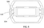
- FIG. 9is a detailed view of the lockable outer housing and inner housing portions of the optical fiber connector of FIG. 5 .
- the flexible portion 532 of the outer housing 528is shown to be coupled to the mating portion 534 of the inner housing 526 via the protruding portion 536.
- FIG. 10is a cross-sectional view of a key 1000 positioned against a portion of the inner housing 1002.
- the keyincludes a surface 1004 having a draft angle, and is positioned against a corresponding inner housing surface 1006 having a draft angle.
- the draft anglemay be about 3 degrees.
- the key 1000may be included in various embodiments disclosed herein, with the advantage that the draft angle prevents the key from easily coming out or slipping out of the connector.
- compositions, methods, and devicesare described in terms of “comprising” various components or steps (interpreted as meaning “including, but not limited to”), the compositions, methods, and devices can also “consist essentially of” or “consist of” the various components and steps, and such terminology should be interpreted as defining essentially closed-member groups.
Landscapes
- Physics & Mathematics (AREA)
- General Physics & Mathematics (AREA)
- Optics & Photonics (AREA)
- Mechanical Coupling Of Light Guides (AREA)
Description
- Demand for bandwidth by enterprises and individual consumers continues to experience exponential growth. To meet this demand efficiently and economically, data centers have to achieve ultra-high density cabling with low loss budgets. Fiber optics have become the standard cabling medium used by data centers to meet the growing needs for data volume and transmission speeds.
- Individual optical fibers are extremely small. For example, even with protective coatings, optical fibers may be only about 250 microns in diameter (only about 4 times the diameter of a human hair). As such, hundreds of fibers can be installed in cables that will take up relatively little space. For connections between cables, however, the fibers are terminated with connectors. Multiple fibers may be arranged within a single connector. For example, multi-fiber connectors such as those using multi-fiber push-on/pull-off (MPO) technology may contain and connect 12 or 24 fibers. Connectors, such as MPO type connectors, generally include a housing portion that contains a ferrule that terminates the ends of the fibers. Ferrules are generally used to retain the ends of the optical fibers for connecting the optical fibers. One type of optical ferrule that may be used with MPO type connectors is an MT (Mechanically Transferable) ferrule.
- Typically, MPO connectors are joined together to connect the optical transmission path of one fiber optic cable to another fiber optic cable or device, and the connection may be made by inserting the MPO connectors in an MPO adapter. An adapter generally includes a housing, or portion of a housing, having at least one port which is configured to receive and hold a connector to facilitate the optical connection of the connector ferrule with the ferrule of another connector or other device. Adapters may be used to facilitate connections contained within a chassis. The term "chassis" as used herein broadly refers to a containment structure for housing electrical components or switching components.
- As a result of the use of pre-terminated fiber assemblies, the issue of maintaining polarity in parallel fiber-optic links is becoming increasingly important. Described simply, polarity maintains proper continuity between transmitters and receivers. In order to make sure that connectors are mated correctly with an adapter, the connector and adapter typically include fixed keying features that permit the connector to be mated with the adapter in generally only one mating configuration. While this has the advantage of preventing a connection that has the wrong polarity, it also can make it difficult to change the polarity of the connection on site.
US 2012/099822 A1 discloses an optical fiber connector in accordance with the preamble of claim 1 having a polarity key connected to the outer housing hindering changing the polarity of the connector on site. Therefore, there remains a need for multi-fiber, fiber optic connectors that have the flexibility of easily changing the polarity of the connector on site.- The object of the invention is achieved by an optical fiber connector according to claim 1 or 2. Preferred embodiments of the invention are disclosed in the dependent claims.
- In one embodiment, an optical fiber connector comprises a ferrule, and an inner housing disposed around at least a portion of the ferrule, the housing comprising a first end for being inserted into an optical fiber adapter, and a second end disposed opposite the first end. The connector further comprises at least one key configured to move along the inner housing so as to change a polarity of said optical fiber connector with respect to the adapter. The connector further comprises an outer housing disposed around at least a portion of the inner housing and configured to slide in a longitudinal direction towards the second end so as to expose at least a portion of said at least one key, wherein the outer housing includes a flexible portion configured to lock to the second end of the inner housing so as to retain the outer housing in a pulled position at the second end of the inner housing.
- In some embodiments, the flexible portion may be configured to engage a mating portion at the second end of the inner housing. In some embodiments, the flexible portion may comprise an opening and the mating portion may comprise a protruding portion configured to engage the opening when the flexible portion is pushed towards the second end. In some embodiments, the opening may have a circular shape. In some embodiments, the connector comprises at least one biasing member for biasing the outer housing towards the first end of the inner housing. In various embodiments, the connector may be an MPO connector. In some embodiments, the flexible portion may comprise a flat surface.
- In some embodiments, the at least one key may include a surface having a draft angle. The inner housing may include a corresponding surface having a corresponding draft angle and configured to retain the at least one key. In one embodiment, the draft angle may be about three degrees.
FIG. 1 depicts perspective views of a polarity changeable MPO connector and adapter;FIGS. 2A and 2B depict mating/polarity configurations of MPO connectors;FIGS. 3A and 3B are representative top and bottom perspective views of a fiber optic connector housing with a detachable key for changing the polarity of the connector;FIG. 4 is a side view of an optical fiber connector having two keys for changing the polarity of the connector;FIG. 5 is perspective view of an optical fiber connector having a lockable outer housing according to aspects of the present disclosure;FIG. 6 is a rear perspective view of the optical fiber connector ofFIG. 5 ;FIG. 7 is a side view of the optical fiber connector ofFIG. 5 ;FIG. 8 is a detailed side view of the flexible portion of the outer housing of the optical fiber connector ofFIG. 5 ;FIG. 9 is a detailed view of the lockable outer housing and inner housing portions of the optical fiber connector ofFIG. 5 ; andFIG. 10 is a cross-sectional view of a key having a draft angle according to aspects of the present disclosure.- So that the polarity of a multi-fiber, fiber optic connector, such as an MPO connector, may be changed, a housing of the connector may be configured to include a removable key that may be positioned at alternate locations on the housing. To change the polarity, the key may be moved from one location to another. In some embodiments, changing the polarity requires a user to slide back and hold back an outer housing of the connector, push a key in or pull it out on one side of the housing, and do the reverse, that is pull the key out or push it in on the opposite side of the housing. However, this process ideally requires "three hands," and may be facilitated in various embodiments disclosed herein, by providing a lockable outer housing of the connector, so as to allow a user to use both hands to move the key.
- Various embodiments provide multi-fiber, fiber optic connectors, such as an MPO connector, having an outer housing configured to be pulled back from the main body or inner housing, then squeezed to lock it, so that the outer housing will not push back to its original position. This allows users to change the position of the key without having to hold back the outer housing, thereby reducing the complexity of the operation needed to change the connector's polarity.
- In various embodiments, the key may be configured such that it does not slide out of the connector easily. For example, the key may be configured to include a surface having a draft angle instead of a flat surface. Further, the main body or inner housing of the connector may include a corresponding surface having a draft angle and configured to engage the key. In one embodiment, the draft angle may be about 3 degrees. The draft angle prevents the key from easily coming out or slipping out of the connector.
- Embodiments disclosed herein provide several advantages, including for example an easy to use polarity change function. If a key is incorrectly aligned with a connector, usually the connector will be rendered unusable. However, the polarity change function allows the connector, such as an MPO connector, to be usable, by easily switching the polarity of the connector. Further, embodiments are configured to prevent the key from easily slipping out of the connector.
- As used herein, the term "optical fiber" is intended to apply to all types of single mode and multi-mode light waveguides, including one or more bare optical fibers, coated optical fibers, loose-tube optical fibers, tight-buffered optical fibers, ribbonized optical fibers, bend performance optical fibers, bend insensitive optical fibers, nanostructured optical fibers or any other expedient for transmitting light signals. A multi-fiber optic cable includes a plurality of the optical fibers. Such cables have a variety of names depending on their particular usage, and may be considered as "trunk cables" or "trunks" when connected to fiber optic modules used to form connections to jumper cables using a select polarity.
- For connection of cables together or with other fiber optic devices, the terminal ends of a cable may include a connector. A connector may include a housing structure configured to interact with and connect with an adapter. An adapter, in a simple form, may include two aligned ports for aligning fiber optic connectors therein to align and connect optical fibers end-to-end. As described herein, the connectors and adapters may be considered multi-fiber connectors and multi-fiber adapters.
- While the following description is directed towards MPO adapters and MPO connectors with MT optical ferrules, the embodiments described may be applicable to other adapters, connectors and ferrule types as well. An embodiment of an MPO connector10 and
adapter 12 is generally represented inFIG. 1 . A first end of the connector10 may include a ferrule14 that may be a multi-fiber ferrule as shown. In addition, the connector10 may have attached thereto, afiber optic cable 15a and cable boot15b (shown only schematically) that may extend from a second end of the connector. - An
adapter 12 may include afirst end 16 having a first plug-inport 18 for receiving the ferrule end of an optical fiber connector10 therein, and may include asecond end 16 having an additional plug-in port22 (not visible) for receiving an additional MPO optical fiber connector, or other type of fiber optic device therein. - For retention of an MPO connector10 within each of the
ports resilient tabs 24a, 24b configured to be displaceable outwardly for insertion and removal of a connector10 into or out of theports Adapters 12 may be configured to be mounted on a chassis panel, and may include mounting flanges26a, 26b to mount the adapter via screws, for example. - A connector10 may include an
inner housing 26 that may surround the ferrule14. In the embodiment depicted, ferrule14 is of the female type - a pairing connector may have a male-type ferrule with two guide pins that fit into the receiving holes of the female ferrule. A connector10 may also include anouter housing 28 that may be slidably disposed about theinner housing 26 adjacent the second end of the connector10. To provide for a predetermined alignment of the fiber optic cables within theadapter 12, the inner housing may include analignment key 30 that is configured to fit within keyingslot 32 of the adapter. For example, in the embodiment depicted, one of the connector10 oradapter 12 will need to be rotated about its axis 180° to align the key30 with theslot 32.Inner housing 26 may slide intoport 18 untiltabs 24a, 24b engage intoslots 34a, 34b of the inner housing. Theouter housing 28 may be moved towards the second end to allow thetabs 24a, 24b to engage intoslots 34a, 34b, and to retain the tabs in the slots, the outer housing may be slid back towards the first end and over the tabs. Theouter housing 28 may be biased towards the first end via springs or alternative types of biasing devices. FIGS. 2A and 2B represent the two different modes of connection alignment to provide for the two different modes of polarity.FIG. 2A may be indicated as representing what may be termed a 'normal' polarity wherein fiber No. 1 of the connector10a may mate with fiber No. 1 of connector10b, and similarly, fiber No. 12 of the connector10a may mate with fiber No. 12 of the connector10b. For this type of alignment, the key30 may be disposed adjacent side A of the ferrule, and the adapter may be keyed accordingly, with the slots32 (FIG. 1 ) in correspondingly opposed surfaces within theadapter 12. To reverse the polarity of the connection between connectors10a, 10b, as shown inFIG. 2B , the key position of the key30 of connector10b would need to be changed to the opposite surface for reversed alignment in anadapter 12, fiber No. 1 of the connector10a may mate with fiber No. 12 of connector10b, and similarly, fiber No. 12 of the connector10a may mate with fiber No. 1 of the connector10b. Alternatively, the key30 of the connector10a could be changed, or in a further embodiment, a different type of adapter may be used, wherein theslots 32 may be aligned on the same internal surface within theadapter 12.- Since an
adapter 12 may already be permanently mounted on a surface, and may have a cable plugged into a back side thereof, an embodiment wherein the location of key30 may be changed would provide for a quick, onsite polarity change. An embodiment of a connector110 having a detachable key130 is represented inFIG. 3 . For clarity, the ferrule and any cable and cabling components are omitted. The connector includes an inner housing126 and an outer housing128. The inner housing has a top side wall 126a and a bottom side wall126b that may be disposed opposite one another, or rotationally, 180° from one another about a central longitudinal axis140. The designations top and bottom are used for reference only as per the orientation shown, and could alternatively be interchanged. In an embodiment, each of the side walls126a and126b may be similar, or essentially the same, and each side wall includes a corresponding slot132a and132b that is configured for receiving the key130. At least a portion of the key130 is configured to be removably insertable into either of the slots132a and132b. The key130 may be configured in conjunction with the walls126a and126b to be removably attached with either the top wall126a or the bottom wall126b. In an embodiment, when key130 is disposed with the top wall126a, the connector110 may be configured to define a first keyed configuration for insertion of the first end of the connector into an adapter in only a first orientation to define a first polarity with respect to the adapter. Alternatively, when key130 is disposed with the bottom wall126b, the connector110 may be configured to define a second keyed configuration for insertion of the first end into the adapter in only a second orientation to define a second polarity with respect to the adapter. As discussed previously, the second polarity may be considered to be opposite to the first polarity. - In some embodiments, two movable keys are used for switching the polarity configuration between a multi-fiber fiber optic connector and a corresponding adapter configured for receiving the connector, as shown for example in
FIG. 4 . The connector includes a connector housing comprising a first end for being inserted into the adapter, a second end disposed opposite the first end, and at least first and second movably displaceable keys displaceable along the housing between a first position adjacent the first end and a second position disposed towards the second end. One of the first and second keys is in its first position and the other of the first and second keys is in its second position to provide a first polarity for the fiber optic connector. The outer housing is positioned around the inner housing, in a default position that is biased towards the first end of the inner housing. The outer housing is configured to be pulled back so as to slide back in a longitudinal direction along the inner housing, allowing slidingly displacing the first key from its corresponding first or second position to the other of the first and second positions, and slidingly displacing the second key from its corresponding first or second position to the other of the first and second positions, to provide a second opposite polarity for the fiber optic connector. The keys are configured to be movable when the outer housing128 is first displaced towards the back end of the inner housing126. FIG. 4 shows a side view of an embodiment wherein thedisplaceable keys outer housing 428 and inner housing426. The connector may be configured with a first polarity with key430a in a forward 'active' position and key430b in a hidden 'inactive' position. To change the polarity, theouter housing 428 may be displaced rearwardly on the inner housing426. After displacing theouter housing 428, keys430 will be partially exposed. Key430a may be slid rearwardly out of its 'active' position into its 'inactive' position and, placing both keys in their 'inactive' position. Key430b may then be slid forwardly out of its 'inactive' hidden position into its 'active' position, and theouter housing 428 may be released to return to its forward position.- While the above-described sequence represents one mode of switching the polarities, the sequence of movements may be altered. For example, key430b may be moved forwardly prior to moving key430a rearwardly.
- In the embodiments described above, the polarity change function may be facilitated by configuring the connector such that the outer housing may be lockable in the pulled back position.
FIG. 5 is perspective view of an optical fiber connector having a lockableouter housing 528 according to aspects of the present disclosure. Thelockable housing 528 is configured to slide over theinner housing 526. Moving theouter housing 528 backwards towards a rear portion of theinner housing 526, and locking it in the rearward position allows a user to easily change the polarity of the connector by using both hands to manipulate thekeys outer housing 528 includes aflexible portion 532 configured to engage a mating portion of theinner housing 526 so as to lock the outer housing in the rearward position. FIG. 6 is a rear perspective view of the optical fiber connector ofFIG. 5 , further showing amating portion 534 of theinner housing 526, having a protrudingportion 536 configured to engage with an opening of theflexible portion 532 of theouter housing 528. As theouter housing 528 is pulled rearwards, theflexible portion 532 may be squeezed so as to couple to themating portion 534 of the inner housing, thereby locking the outer housing in the rearward position.- In some embodiments, the
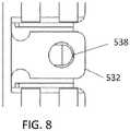
flexible portion 532 may be curved. In other embodiments, theflexible portion 532 may be flat so as to bend more easily. In some embodiments, the protrudingportion 536 may be shaped cylindrically or as a dome, such that it does not have sharp corners. Theflexible portion 532 may have a corresponding opening that is circularly shaped. FIG. 7 is a side view of the optical fiber connector ofFIG. 5 , further showing the first key530a and the second key530b disposed at opposite sides of theinner housing 526.FIG. 8 is a detailed side view of theflexible portion 532 of theouter housing 528 of the optical fiber connector ofFIG. 5 , further showing a circularly shapedopening 538. Theopening 538 is configured to receive the protrudingportion 536 of themating portion 534 of theinner housing 526 as shown inFIG. 6 .FIG. 9 is a detailed view of the lockable outer housing and inner housing portions of the optical fiber connector ofFIG. 5 . Theflexible portion 532 of theouter housing 528 is shown to be coupled to themating portion 534 of theinner housing 526 via the protrudingportion 536.FIG. 10 is a cross-sectional view of a key 1000 positioned against a portion of theinner housing 1002. The key includes asurface 1004 having a draft angle, and is positioned against a correspondinginner housing surface 1006 having a draft angle. In one embodiment, the draft angle may be about 3 degrees. The key 1000 may be included in various embodiments disclosed herein, with the advantage that the draft angle prevents the key from easily coming out or slipping out of the connector.- In the various embodiments disclosed herein, the keys and housing components, may be formed of rigid polymers or metals, for example. In general, any type of substantially rigid material may be used. The material should have a rigidity sufficient to retain the necessary engagement between the key and the housing so that the key remains in place except when a force is applied to remove the key.
- Various parts, components or configurations described with respect to any one embodiment above may also be adapted to any others of the embodiments provided.
- This disclosure is not limited to the particular systems, devices and methods described, as these may vary. The terminology used in the description is for the purpose of describing the particular versions or embodiments only.
- In the above detailed description, reference is made to the accompanying drawings, which form a part hereof. In the drawings, similar symbols typically identify similar components, unless context dictates otherwise. The illustrative embodiments described in the detailed description, drawings, and claims are not meant to be limiting. Other embodiments may be used, and other changes may be made, without departing from the scope of the claims. It will be readily understood that the aspects of the present disclosure, as generally described herein, and illustrated in the figures, can be arranged, substituted, combined, separated, and designed in a wide variety of different configurations, all of which are explicitly contemplated herein.
- The present disclosure is not to be limited in terms of the particular embodiments described in this application, which are intended as illustrations of various aspects. Many modifications and variations can be made without departing from the scope of the claims, as will be apparent to those skilled in the art. Functionally equivalent apparatuses within the scope of the disclosure, in addition to those enumerated herein, will be apparent to those skilled in the art from the foregoing descriptions. Such modifications and variations are intended to fall within the scope of the appended claims. The present disclosure is to be limited only by the terms of the appended claims. It is also to be understood that the terminology used herein is for the purpose of describing particular embodiments only, and is not intended to be limiting.
- As used in this document, the singular forms "a," "an," and "the" include plural references unless the context clearly dictates otherwise. Unless defined otherwise, all technical and scientific terms used herein have the same meanings as commonly understood by one of ordinary skill in the art. Nothing in this disclosure is to be construed as an admission that the embodiments described in this disclosure are not entitled to antedate such disclosure by virtue of prior invention. As used in this document, the term "comprising" means "including, but not limited to."
- While various compositions, methods, and devices are described in terms of "comprising" various components or steps (interpreted as meaning "including, but not limited to"), the compositions, methods, and devices can also "consist essentially of" or "consist of" the various components and steps, and such terminology should be interpreted as defining essentially closed-member groups.
- With respect to the use of substantially any plural and/or singular terms herein, those having skill in the art can translate from the plural to the singular and/or from the singular to the plural as is appropriate to the context and/or application. The various singular/plural permutations may be expressly set forth herein for sake of clarity.
- It will be understood by those within the art that, in general, terms used herein, and especially in the appended claims are generally intended as "open" terms (e.g., the term "including" should be interpreted as "including but not limited to," the term "having" should be interpreted as "having at least," the term "includes" should be interpreted as "includes but is not limited to," etc.). It will be further understood by those within the art that if a specific number of an introduced claim recitation is intended, such an intent will be explicitly recited in the claim, and in the absence of such recitation no such intent is present. For example, as an aid to understanding, the following appended claims may contain usage of the introductory phrases "at least one" and "one or more" to introduce claim recitations. However, the use of such phrases should not be construed to imply that the introduction of a claim recitation by the indefinite articles "a" or "an" limits any particular claim containing such introduced claim recitation to embodiments containing only one such recitation, even when the same claim includes the introductory phrases "one or more" or "at least one" and indefinite articles such as "a" or "an" (e.g., "a" and/or "an" should be interpreted to mean "at least one" or "one or more"); the same holds true for the use of definite articles used to introduce claim recitations. In addition, even if a specific number of an introduced claim recitation is explicitly recited, those skilled in the art will recognize that such recitation should be interpreted to mean at least the recited number (e.g., the bare recitation of "two recitations," without other modifiers, means at least two recitations, or two or more recitations). Furthermore, in those instances where a convention analogous to "at least one of A, B, and C, etc." is used, in general such a construction is intended in the sense one having skill in the art would understand the convention (e.g., " a system having at least one of A, B, and C" would include but not be limited to systems that have A alone, B alone, C alone, A and B together, A and C together, B and C together, and/or A, B, and C together, etc.). In those instances where a convention analogous to "at least one of A, B, or C, etc." is used, in general such a construction is intended in the sense one having skill in the art would understand the convention (e.g., " a system having at least one of A, B, or C" would include but not be limited to systems that have A alone, B alone, C alone, A and B together, A and C together, B and C together, and/or A, B, and C together, etc.). It will be further understood by those within the art that virtually any disjunctive word and/or phrase presenting two or more alternative terms, whether in the description, claims, or drawings, should be understood to contemplate the possibilities of including one of the terms, either of the terms, or both terms. For example, the phrase "A or B" will be understood to include the possibilities of "A" or "B" or "A and B."
- Various of the above-disclosed and other features and functions, or alternatives thereof, may be combined into many other different systems or applications.
Claims (11)
- Optical fiber connector (10, 10a, 10b; 110) comprising:a ferrule (14);an inner housing (26; 126; 426; 526; 1002) disposed around at least a portion of the ferrule (14), the inner housing (26; 126; 426; 526; 1002) comprising a first end (16) for being inserted into an optical fiber adapter (12), and a second end disposed opposite the first end (16);at least one key (30; 130; 430a, 430b; 530a, 530b; 1000); andan outer housing (28; 128; 428; 528) disposed around at least a portion of the inner housing (26; 126; 426; 526; 1002), wherein the outer housing (28; 128; 428; 528) includes a flexible portion (532) configured to lock to the second end of the inner housing (26; 126; 426; 526; 1002) so as to retain the outer housing (28; 128; 428; 528) in a pulled position at the second end of the inner housing (26; 126; 426; 526; 1002),characterized in that the at least one key (30; 130; 430a, 430b; 530a, 530b; 1000) is configured to move along the inner housing (26; 126; 426; 526; 1002) so as to change a polarity of said optical fiber connector with respect to the adapter (12),the outer housing (28; 128; 428; 528) is configured to slide in a longitudinal direction towards the second end of the inner housing (26; 126; 426; 526; 1002) so as to expose at least a portion of said at least one key (30; 130; 430a, 430b; 530a, 530b; 1000),the at least one key (30; 130; 430a, 430b; 530a, 530b; 1000) comprises a detachable key (130),the inner housing (26; 126; 426; 526; 1002) has a top side wall (126a) and a bottom side wall (126b), each side wall including a corresponding slot (132a, 132b) configured for receiving the at least one key (30; 130; 430a, 430b; 530a, 530b; 1000), andat least a portion of the at least one key (30; 130; 430a, 430b; 530a, 530b; 1000) is configured to be removably insertable into either of the slots (132a, 132b).
- Optical fiber connector (10, 10a, 10b; 110) comprising:a ferrule (14);an inner housing (26; 126; 426; 526; 1002) disposed around at least a portion of the ferrule (14), the inner housing (26; 126; 426; 526; 1002) comprising a first end (16) for being inserted into an optical fiber adapter (12), and a second end disposed opposite the first end (16);at least one key (30; 130; 430a, 430b; 530a, 530b; 1000); andan outer housing (28; 128; 428; 528) disposed around at least a portion of the inner housing (26; 126; 426; 526; 1002), wherein the outer housing (28; 128; 428; 528) includes a flexible portion (532) configured to lock to the second end of the inner housing (26; 126; 426; 526; 1002) so as to retain the outer housing (28; 128; 428; 528) in a pulled position at the second end of the inner housing (26; 126; 426; 526; 1002),characterized in that the at least one key (30; 130; 430a, 430b; 530a, 530b; 1000) is configured to move along the inner housing (26; 126; 426; 526; 1002) so as to change a polarity of said optical fiber connector with respect to the adapter (12),the outer housing (28; 128; 428; 528) is configured to slide in a longitudinal direction towards the second end of the inner housing (26; 126; 426; 526; 1002) so as to expose at least a portion of said at least one key (30; 130; 430a, 430b; 530a, 530b; 1000),the at least one key (30; 130; 430a, 430b; 530a, 530b; 1000) comprises at least first and second movably displaceable keys (430a, 430b) displaceable along the inner housing (26; 126; 426; 526; 1002) between a first position adjacent the first end (16) and a second position disposed towards the second end, wherein one of the first and second movably displaceable keys (430a, 430b) is in its first position and the other of the first and second movably displaceable keys (430a, 430b) is in its second position to provide a first polarity for the fiber optic connector (10, 10a, 10b; 110), wherein the outer housing (28; 128; 428; 528) is positionable around the inner housing (26; 126; 426; 526; 1002), in a default position that is biased towards the first end (16) of the inner housing (26; 126; 426; 526; 1002), wherein the outer housing (28; 128; 428; 528) is configurable to be pulled back so as to slide back in a longitudinal direction along the inner housing (26; 126; 426; 526; 1002), allowing slidingly displacing the first movably displaceable key (430a) from its corresponding first or second position to the other of the first and second positions, and slidingly displacing the second movably displaceable key (430b) from its corresponding first or second position to the other of the first and second positions, to provide a second opposite polarity for the fiber optic connector (10, 10a, 10b; 110), wherein the first and second movably displaceable keys (430a, 430b) are configured to be movable when the outer housing (28; 128; 428; 528) is first displaced towards the back end of the inner housing (26; 126; 426; 526; 1002), wherein the first and second movably displaceable keys (430a, 430b) are displaceable relative to the outer housing (28; 128; 428; 528) and the inner housing (26; 126; 426; 526; 1002), wherein, to change the polarity, the outer housing (28; 128; 428; 528) is displaceable rearwardly on the inner housing (26; 126; 426; 526; 1002).
- Optical fiber connector (10, 10a, 10b; 110) according to any of the preceding claims, wherein the flexible portion (532) is configured to engage a mating portion (534) at the second end of the inner housing (26; 126; 426; 526; 1002).
- Optical fiber connector (10, 10a, 10b; 110) according to claim 3, wherein the flexible portion (532) comprises an opening (538) and the mating portion (534) comprises a protruding portion (536) configured to engage the opening (538) when the flexible portion (532) is pushed towards the second end.
- Optical fiber connector (10, 10a, 10b; 110) according to claim 4, wherein the opening (538) has a circular shape.
- Optical fiber connector (10, 10a, 10b; 110) according to any of the preceding claims, wherein the connector comprises at least one biasing member for biasing the outer housing (28; 128; 428; 528) towards the first end (16) of the inner housing (26; 126; 426; 526; 1002).
- Optical fiber connector (10, 10a, 10b; 110) according to any of the preceding claims, wherein said connector (10, 10a, 10b; 110) is an MPO connector.
- Optical fiber connector (10, 10a, 10b; 110) according to any of the preceding claims, wherein the flexible portion (532) comprises a flat surface.
- Optical fiber connector (10, 10a, 10b; 110) according to any of the preceding claims, wherein the at least one key (1000) includes a surface (1004) having a draft angle.
- Optical fiber connector (10, 10a, 10b; 110) according to claim 9, wherein the inner housing (26; 126; 426; 526; 1002) includes a corresponding surface (1006) having a corresponding draft angle and configured to retain the at least one key (1000).
- Optical fiber connector (10, 10a, 10b; 110) according to claim 10, wherein the draft angle is about three degrees.
Applications Claiming Priority (2)
| Application Number | Priority Date | Filing Date | Title |
|---|---|---|---|
| US15/205,773US9939589B2 (en) | 2016-07-08 | 2016-07-08 | Polarity changeable connector |
| PCT/US2017/040178WO2018009426A1 (en) | 2016-07-08 | 2017-06-30 | Polarity changeable connector |
Publications (3)
| Publication Number | Publication Date |
|---|---|
| EP3482243A1 EP3482243A1 (en) | 2019-05-15 |
| EP3482243A4 EP3482243A4 (en) | 2020-01-22 |
| EP3482243B1true EP3482243B1 (en) | 2022-05-04 |
Family
ID=60892768
Family Applications (1)
| Application Number | Title | Priority Date | Filing Date |
|---|---|---|---|
| EP17824733.4AActiveEP3482243B1 (en) | 2016-07-08 | 2017-06-30 | Polarity changeable connector |
Country Status (4)
| Country | Link |
|---|---|
| US (4) | US9939589B2 (en) |
| EP (1) | EP3482243B1 (en) |
| CN (3) | CN113253395B (en) |
| WO (1) | WO2018009426A1 (en) |
Families Citing this family (26)
| Publication number | Priority date | Publication date | Assignee | Title |
|---|---|---|---|---|
| US10712507B2 (en)* | 2015-12-19 | 2020-07-14 | US Conec, Ltd | Field changeable fiber optic connector polarity keying |
| US10921529B2 (en)* | 2016-11-13 | 2021-02-16 | USConec, Ltd | Long push pull sleeve indicating orientation |
| US10228521B2 (en) | 2016-12-05 | 2019-03-12 | Senko Advanced Components, Inc. | Narrow width adapters and connectors with modular latching arm |
| US10295759B2 (en) | 2017-05-18 | 2019-05-21 | Senko Advanced Components, Inc. | Optical connector with forward-biasing projections |
| JP1598020S (en)* | 2017-08-02 | 2018-02-19 | ||
| US10444442B2 (en) | 2017-11-03 | 2019-10-15 | Senko Advanced Components, Inc. | MPO optical fiber connector |
| US11016250B2 (en)* | 2017-12-19 | 2021-05-25 | Us Conec, Ltd. | Mini duplex connector with push-pull polarity mechanism, carrier, and rail-receiving crimp body |
| US11041993B2 (en) | 2018-04-19 | 2021-06-22 | Senko Advanced Components, Inc. | Fiber optic adapter with removable insert for polarity change and removal tool for the same |
| US10921528B2 (en) | 2018-06-07 | 2021-02-16 | Senko Advanced Components, Inc. | Dual spring multi-fiber optic connector |
| EP4481452A3 (en)* | 2018-06-19 | 2025-03-26 | CommScope Technologies LLC | Multi-fiber fiber optic connector having enhanced functionality |
| WO2020118176A1 (en)* | 2018-12-06 | 2020-06-11 | Senko Advanced Components, Inc | Ultra-small form factor optical connectors with polarity change and method of use |
| US11181696B2 (en) | 2019-02-22 | 2021-11-23 | Senko Advanced Components, Inc. | Adapter assembly having a return spring with a push-pull tab |
| WO2020172661A2 (en)* | 2019-02-22 | 2020-08-27 | Senko Advanced Components, Inc | Adapter assembly having a return spring with a push-pull tab |
| CN110261968A (en)* | 2019-05-06 | 2019-09-20 | 南京华脉科技股份有限公司 | A kind of self-locking type polarity is adjustable multi-core connector and fixture |
| TWM584438U (en)* | 2019-07-03 | 2019-10-01 | 建毅科技股份有限公司 | Optical fibre connector |
| CN110376684B (en)* | 2019-07-31 | 2024-10-29 | 新确精密科技(深圳)有限公司 | Optical fiber connector with changeable polarity |
| US11353664B1 (en) | 2019-08-21 | 2022-06-07 | Senko Advanced Components, Inc. | Fiber optic connector |
| US11726269B2 (en)* | 2019-09-24 | 2023-08-15 | Senko Advanced Components, Inc. | Lockable MPO connector for securing within a port of an adapter having a unique removal key |
| WO2021097304A1 (en) | 2019-11-13 | 2021-05-20 | Senko Advanced Components, Inc. | Fiber optic connector |
| TWM593556U (en)* | 2019-11-26 | 2020-04-11 | 大陸商深圳望得源科技有限公司 | Optical fiber connector and optical fiber connector |
| JP7542987B2 (en) | 2020-05-01 | 2024-09-02 | 株式会社フジクラ | Optical connector system and plug |
| US20210382238A1 (en) | 2020-06-09 | 2021-12-09 | Senko Advanced Components, Inc. | Multiport assembly and associated components |
| CN111552036B (en)* | 2020-06-09 | 2025-06-27 | 江苏宇特光电科技股份有限公司 | A polarity-changing connector |
| TWM615335U (en)* | 2020-09-23 | 2021-08-11 | 建毅科技股份有限公司 | Optical fibre connector |
| IT202000023317A1 (en) | 2020-10-02 | 2022-04-02 | Prysmian Spa | CONNECTOR FOR OPTICAL FIBER AND RELATED METHOD |
| US11543601B1 (en)* | 2021-07-22 | 2023-01-03 | Suncall Technologies (Sz) Co., Ltd | MPO connector with high-density release clip and connector release tool |
Family Cites Families (8)
| Publication number | Priority date | Publication date | Assignee | Title |
|---|---|---|---|---|
| US5041025A (en) | 1990-01-31 | 1991-08-20 | Thomas & Betts Corporation | Interconnectable components employing a multi-positionable key |
| US8636424B2 (en)* | 2010-10-22 | 2014-01-28 | Panduit Corp. | Optical communication connector |
| WO2012151175A2 (en)* | 2011-05-04 | 2012-11-08 | The Siemon Company | Fiber optic connector with polarity change |
| US8770863B2 (en)* | 2012-06-04 | 2014-07-08 | Corning Cable Systems Llc | Multi-fiber fiber-optic connector with switchable polarity key |
| WO2015191024A1 (en)* | 2014-06-09 | 2015-12-17 | Senko Advanced Components, Inc. | Reduced-profile connectors, adapters, and connection assemblies thereof |
| US9829645B2 (en)* | 2014-06-30 | 2017-11-28 | Nexans | Reversible polarity MPO fiber optic connector |
| US9658409B2 (en)* | 2015-03-03 | 2017-05-23 | Senko Advanced Components, Inc. | Optical fiber connector with changeable polarity |
| US11765533B2 (en) | 2016-12-29 | 2023-09-19 | Gmems Tech Shenzhen Limited | Capacitive microphone with two signal outputs that are additive inverse of each other |
- 2016
- 2016-07-08USUS15/205,773patent/US9939589B2/enactiveActive
- 2017
- 2017-03-13USUS15/456,792patent/US10146012B2/enactiveActive
- 2017-06-30CNCN202110508456.9Apatent/CN113253395B/enactiveActive
- 2017-06-30WOPCT/US2017/040178patent/WO2018009426A1/ennot_activeCeased
- 2017-06-30EPEP17824733.4Apatent/EP3482243B1/enactiveActive
- 2017-06-30CNCN201780042392.XApatent/CN109416445B/enactiveActive
- 2017-06-30CNCN202010277489.2Apatent/CN111308617A/ennot_activeWithdrawn
- 2018
- 2018-11-01USUS16/178,253patent/US10393969B2/ennot_activeExpired - Fee Related
- 2019
- 2019-07-16USUS16/513,006patent/US10725247B2/enactiveActive
Also Published As
| Publication number | Publication date |
|---|---|
| US20180011258A1 (en) | 2018-01-11 |
| CN113253395B (en) | 2023-09-12 |
| EP3482243A1 (en) | 2019-05-15 |
| CN109416445A (en) | 2019-03-01 |
| US9939589B2 (en) | 2018-04-10 |
| CN113253395A (en) | 2021-08-13 |
| WO2018009426A1 (en) | 2018-01-11 |
| US20190339459A1 (en) | 2019-11-07 |
| US10725247B2 (en) | 2020-07-28 |
| CN109416445B (en) | 2021-05-28 |
| US20190072724A1 (en) | 2019-03-07 |
| US10393969B2 (en) | 2019-08-27 |
| EP3482243A4 (en) | 2020-01-22 |
| US10146012B2 (en) | 2018-12-04 |
| US20180011254A1 (en) | 2018-01-11 |
| CN111308617A (en) | 2020-06-19 |
Similar Documents
| Publication | Publication Date | Title |
|---|---|---|
| EP3482243B1 (en) | Polarity changeable connector | |
| US12259585B2 (en) | Optical fiber connector with changeable polarity | |
| US11073662B2 (en) | Optical fiber connector with changeable gender | |
| EP3403122B1 (en) | Fiber optic connector assemblies with adjustable polarity | |
| US10139572B2 (en) | Duplex fiber optic components suitable for polarity reversal | |
| US20170307830A1 (en) | Polarity Changeable LC Duplex Adapter | |
| US10545297B2 (en) | SC low profile connector |
Legal Events
| Date | Code | Title | Description |
|---|---|---|---|
| STAA | Information on the status of an ep patent application or granted ep patent | Free format text:STATUS: THE INTERNATIONAL PUBLICATION HAS BEEN MADE | |
| PUAI | Public reference made under article 153(3) epc to a published international application that has entered the european phase | Free format text:ORIGINAL CODE: 0009012 | |
| STAA | Information on the status of an ep patent application or granted ep patent | Free format text:STATUS: REQUEST FOR EXAMINATION WAS MADE | |
| 17P | Request for examination filed | Effective date:20181210 | |
| AK | Designated contracting states | Kind code of ref document:A1 Designated state(s):AL AT BE BG CH CY CZ DE DK EE ES FI FR GB GR HR HU IE IS IT LI LT LU LV MC MK MT NL NO PL PT RO RS SE SI SK SM TR | |
| AX | Request for extension of the european patent | Extension state:BA ME | |
| DAV | Request for validation of the european patent (deleted) | ||
| DAX | Request for extension of the european patent (deleted) | ||
| A4 | Supplementary search report drawn up and despatched | Effective date:20191220 | |
| RIC1 | Information provided on ipc code assigned before grant | Ipc:G02B 6/38 20060101AFI20191216BHEP | |
| STAA | Information on the status of an ep patent application or granted ep patent | Free format text:STATUS: EXAMINATION IS IN PROGRESS | |
| 17Q | First examination report despatched | Effective date:20201126 | |
| GRAP | Despatch of communication of intention to grant a patent | Free format text:ORIGINAL CODE: EPIDOSNIGR1 | |
| STAA | Information on the status of an ep patent application or granted ep patent | Free format text:STATUS: GRANT OF PATENT IS INTENDED | |
| INTG | Intention to grant announced | Effective date:20211125 | |
| GRAS | Grant fee paid | Free format text:ORIGINAL CODE: EPIDOSNIGR3 | |
| GRAA | (expected) grant | Free format text:ORIGINAL CODE: 0009210 | |
| STAA | Information on the status of an ep patent application or granted ep patent | Free format text:STATUS: THE PATENT HAS BEEN GRANTED | |
| AK | Designated contracting states | Kind code of ref document:B1 Designated state(s):AL AT BE BG CH CY CZ DE DK EE ES FI FR GB GR HR HU IE IS IT LI LT LU LV MC MK MT NL NO PL PT RO RS SE SI SK SM TR | |
| REG | Reference to a national code | Ref country code:GB Ref legal event code:FG4D | |
| REG | Reference to a national code | Ref country code:CH Ref legal event code:EP | |
| REG | Reference to a national code | Ref country code:AT Ref legal event code:REF Ref document number:1489663 Country of ref document:AT Kind code of ref document:T Effective date:20220515 | |
| REG | Reference to a national code | Ref country code:IE Ref legal event code:FG4D Ref country code:DE Ref legal event code:R096 Ref document number:602017057043 Country of ref document:DE | |
| REG | Reference to a national code | Ref country code:LT Ref legal event code:MG9D | |
| RAP4 | Party data changed (patent owner data changed or rights of a patent transferred) | Owner name:SENKO ADVANCED COMPONENTS INC. | |
| REG | Reference to a national code | Ref country code:NL Ref legal event code:MP Effective date:20220504 | |
| REG | Reference to a national code | Ref country code:DE Ref legal event code:R081 Ref document number:602017057043 Country of ref document:DE Owner name:SENKO ADVANCED COMPONENTS, INC., HUDSON, US Free format text:FORMER OWNER: SENKO ADVANCED COMPONENTS, INC., MARLBOROUGH, MA, US | |
| REG | Reference to a national code | Ref country code:AT Ref legal event code:MK05 Ref document number:1489663 Country of ref document:AT Kind code of ref document:T Effective date:20220504 | |
| PG25 | Lapsed in a contracting state [announced via postgrant information from national office to epo] | Ref country code:SE Free format text:LAPSE BECAUSE OF FAILURE TO SUBMIT A TRANSLATION OF THE DESCRIPTION OR TO PAY THE FEE WITHIN THE PRESCRIBED TIME-LIMIT Effective date:20220504 Ref country code:PT Free format text:LAPSE BECAUSE OF FAILURE TO SUBMIT A TRANSLATION OF THE DESCRIPTION OR TO PAY THE FEE WITHIN THE PRESCRIBED TIME-LIMIT Effective date:20220905 Ref country code:NO Free format text:LAPSE BECAUSE OF FAILURE TO SUBMIT A TRANSLATION OF THE DESCRIPTION OR TO PAY THE FEE WITHIN THE PRESCRIBED TIME-LIMIT Effective date:20220804 Ref country code:NL Free format text:LAPSE BECAUSE OF FAILURE TO SUBMIT A TRANSLATION OF THE DESCRIPTION OR TO PAY THE FEE WITHIN THE PRESCRIBED TIME-LIMIT Effective date:20220504 Ref country code:LT Free format text:LAPSE BECAUSE OF FAILURE TO SUBMIT A TRANSLATION OF THE DESCRIPTION OR TO PAY THE FEE WITHIN THE PRESCRIBED TIME-LIMIT Effective date:20220504 Ref country code:HR Free format text:LAPSE BECAUSE OF FAILURE TO SUBMIT A TRANSLATION OF THE DESCRIPTION OR TO PAY THE FEE WITHIN THE PRESCRIBED TIME-LIMIT Effective date:20220504 Ref country code:GR Free format text:LAPSE BECAUSE OF FAILURE TO SUBMIT A TRANSLATION OF THE DESCRIPTION OR TO PAY THE FEE WITHIN THE PRESCRIBED TIME-LIMIT Effective date:20220805 Ref country code:FI Free format text:LAPSE BECAUSE OF FAILURE TO SUBMIT A TRANSLATION OF THE DESCRIPTION OR TO PAY THE FEE WITHIN THE PRESCRIBED TIME-LIMIT Effective date:20220504 Ref country code:ES Free format text:LAPSE BECAUSE OF FAILURE TO SUBMIT A TRANSLATION OF THE DESCRIPTION OR TO PAY THE FEE WITHIN THE PRESCRIBED TIME-LIMIT Effective date:20220504 Ref country code:BG Free format text:LAPSE BECAUSE OF FAILURE TO SUBMIT A TRANSLATION OF THE DESCRIPTION OR TO PAY THE FEE WITHIN THE PRESCRIBED TIME-LIMIT Effective date:20220804 Ref country code:AT Free format text:LAPSE BECAUSE OF FAILURE TO SUBMIT A TRANSLATION OF THE DESCRIPTION OR TO PAY THE FEE WITHIN THE PRESCRIBED TIME-LIMIT Effective date:20220504 | |
| PG25 | Lapsed in a contracting state [announced via postgrant information from national office to epo] | Ref country code:RS Free format text:LAPSE BECAUSE OF FAILURE TO SUBMIT A TRANSLATION OF THE DESCRIPTION OR TO PAY THE FEE WITHIN THE PRESCRIBED TIME-LIMIT Effective date:20220504 Ref country code:PL Free format text:LAPSE BECAUSE OF FAILURE TO SUBMIT A TRANSLATION OF THE DESCRIPTION OR TO PAY THE FEE WITHIN THE PRESCRIBED TIME-LIMIT Effective date:20220504 Ref country code:LV Free format text:LAPSE BECAUSE OF FAILURE TO SUBMIT A TRANSLATION OF THE DESCRIPTION OR TO PAY THE FEE WITHIN THE PRESCRIBED TIME-LIMIT Effective date:20220504 Ref country code:IS Free format text:LAPSE BECAUSE OF FAILURE TO SUBMIT A TRANSLATION OF THE DESCRIPTION OR TO PAY THE FEE WITHIN THE PRESCRIBED TIME-LIMIT Effective date:20220904 | |
| PG25 | Lapsed in a contracting state [announced via postgrant information from national office to epo] | Ref country code:SM Free format text:LAPSE BECAUSE OF FAILURE TO SUBMIT A TRANSLATION OF THE DESCRIPTION OR TO PAY THE FEE WITHIN THE PRESCRIBED TIME-LIMIT Effective date:20220504 Ref country code:SK Free format text:LAPSE BECAUSE OF FAILURE TO SUBMIT A TRANSLATION OF THE DESCRIPTION OR TO PAY THE FEE WITHIN THE PRESCRIBED TIME-LIMIT Effective date:20220504 Ref country code:RO Free format text:LAPSE BECAUSE OF FAILURE TO SUBMIT A TRANSLATION OF THE DESCRIPTION OR TO PAY THE FEE WITHIN THE PRESCRIBED TIME-LIMIT Effective date:20220504 Ref country code:EE Free format text:LAPSE BECAUSE OF FAILURE TO SUBMIT A TRANSLATION OF THE DESCRIPTION OR TO PAY THE FEE WITHIN THE PRESCRIBED TIME-LIMIT Effective date:20220504 Ref country code:DK Free format text:LAPSE BECAUSE OF FAILURE TO SUBMIT A TRANSLATION OF THE DESCRIPTION OR TO PAY THE FEE WITHIN THE PRESCRIBED TIME-LIMIT Effective date:20220504 Ref country code:CZ Free format text:LAPSE BECAUSE OF FAILURE TO SUBMIT A TRANSLATION OF THE DESCRIPTION OR TO PAY THE FEE WITHIN THE PRESCRIBED TIME-LIMIT Effective date:20220504 | |
| REG | Reference to a national code | Ref country code:DE Ref legal event code:R097 Ref document number:602017057043 Country of ref document:DE | |
| REG | Reference to a national code | Ref country code:BE Ref legal event code:MM Effective date:20220630 | |
| PG25 | Lapsed in a contracting state [announced via postgrant information from national office to epo] | Ref country code:MC Free format text:LAPSE BECAUSE OF FAILURE TO SUBMIT A TRANSLATION OF THE DESCRIPTION OR TO PAY THE FEE WITHIN THE PRESCRIBED TIME-LIMIT Effective date:20220504 | |
| PLBE | No opposition filed within time limit | Free format text:ORIGINAL CODE: 0009261 | |
| STAA | Information on the status of an ep patent application or granted ep patent | Free format text:STATUS: NO OPPOSITION FILED WITHIN TIME LIMIT | |
| PG25 | Lapsed in a contracting state [announced via postgrant information from national office to epo] | Ref country code:AL Free format text:LAPSE BECAUSE OF FAILURE TO SUBMIT A TRANSLATION OF THE DESCRIPTION OR TO PAY THE FEE WITHIN THE PRESCRIBED TIME-LIMIT Effective date:20220504 | |
| 26N | No opposition filed | Effective date:20230207 | |
| PG25 | Lapsed in a contracting state [announced via postgrant information from national office to epo] | Ref country code:LU Free format text:LAPSE BECAUSE OF NON-PAYMENT OF DUE FEES Effective date:20220630 Ref country code:IE Free format text:LAPSE BECAUSE OF NON-PAYMENT OF DUE FEES Effective date:20220630 Ref country code:FR Free format text:LAPSE BECAUSE OF NON-PAYMENT OF DUE FEES Effective date:20220704 | |
| PG25 | Lapsed in a contracting state [announced via postgrant information from national office to epo] | Ref country code:SI Free format text:LAPSE BECAUSE OF FAILURE TO SUBMIT A TRANSLATION OF THE DESCRIPTION OR TO PAY THE FEE WITHIN THE PRESCRIBED TIME-LIMIT Effective date:20220504 Ref country code:BE Free format text:LAPSE BECAUSE OF NON-PAYMENT OF DUE FEES Effective date:20220630 | |
| PG25 | Lapsed in a contracting state [announced via postgrant information from national office to epo] | Ref country code:IT Free format text:LAPSE BECAUSE OF FAILURE TO SUBMIT A TRANSLATION OF THE DESCRIPTION OR TO PAY THE FEE WITHIN THE PRESCRIBED TIME-LIMIT Effective date:20220504 | |
| PG25 | Lapsed in a contracting state [announced via postgrant information from national office to epo] | Ref country code:HU Free format text:LAPSE BECAUSE OF FAILURE TO SUBMIT A TRANSLATION OF THE DESCRIPTION OR TO PAY THE FEE WITHIN THE PRESCRIBED TIME-LIMIT; INVALID AB INITIO Effective date:20170630 | |
| PG25 | Lapsed in a contracting state [announced via postgrant information from national office to epo] | Ref country code:MK Free format text:LAPSE BECAUSE OF FAILURE TO SUBMIT A TRANSLATION OF THE DESCRIPTION OR TO PAY THE FEE WITHIN THE PRESCRIBED TIME-LIMIT Effective date:20220504 Ref country code:CY Free format text:LAPSE BECAUSE OF FAILURE TO SUBMIT A TRANSLATION OF THE DESCRIPTION OR TO PAY THE FEE WITHIN THE PRESCRIBED TIME-LIMIT Effective date:20220504 | |
| PG25 | Lapsed in a contracting state [announced via postgrant information from national office to epo] | Ref country code:MT Free format text:LAPSE BECAUSE OF FAILURE TO SUBMIT A TRANSLATION OF THE DESCRIPTION OR TO PAY THE FEE WITHIN THE PRESCRIBED TIME-LIMIT Effective date:20220504 | |
| PGFP | Annual fee paid to national office [announced via postgrant information from national office to epo] | Ref country code:CH Payment date:20240701 Year of fee payment:8 | |
| PG25 | Lapsed in a contracting state [announced via postgrant information from national office to epo] | Ref country code:BG Free format text:LAPSE BECAUSE OF FAILURE TO SUBMIT A TRANSLATION OF THE DESCRIPTION OR TO PAY THE FEE WITHIN THE PRESCRIBED TIME-LIMIT Effective date:20220504 | |
| PG25 | Lapsed in a contracting state [announced via postgrant information from national office to epo] | Ref country code:BG Free format text:LAPSE BECAUSE OF FAILURE TO SUBMIT A TRANSLATION OF THE DESCRIPTION OR TO PAY THE FEE WITHIN THE PRESCRIBED TIME-LIMIT Effective date:20220504 | |
| PGFP | Annual fee paid to national office [announced via postgrant information from national office to epo] | Ref country code:DE Payment date:20250618 Year of fee payment:9 | |
| PGFP | Annual fee paid to national office [announced via postgrant information from national office to epo] | Ref country code:GB Payment date:20250618 Year of fee payment:9 |