EP3479791B1 - Surgical robotic automation with tracking markers - Google Patents
Surgical robotic automation with tracking markersDownload PDFInfo
- Publication number
- EP3479791B1 EP3479791B1EP18209781.6AEP18209781AEP3479791B1EP 3479791 B1EP3479791 B1EP 3479791B1EP 18209781 AEP18209781 AEP 18209781AEP 3479791 B1EP3479791 B1EP 3479791B1
- Authority
- EP
- European Patent Office
- Prior art keywords
- robot
- markers
- effector
- tracking
- guide tube
- Prior art date
- Legal status (The legal status is an assumption and is not a legal conclusion. Google has not performed a legal analysis and makes no representation as to the accuracy of the status listed.)
- Active
Links
Images


Classifications
- A—HUMAN NECESSITIES
- A61—MEDICAL OR VETERINARY SCIENCE; HYGIENE
- A61B—DIAGNOSIS; SURGERY; IDENTIFICATION
- A61B90/00—Instruments, implements or accessories specially adapted for surgery or diagnosis and not covered by any of the groups A61B1/00 - A61B50/00, e.g. for luxation treatment or for protecting wound edges
- A61B90/90—Identification means for patients or instruments, e.g. tags
- A61B90/98—Identification means for patients or instruments, e.g. tags using electromagnetic means, e.g. transponders
- A—HUMAN NECESSITIES
- A61—MEDICAL OR VETERINARY SCIENCE; HYGIENE
- A61B—DIAGNOSIS; SURGERY; IDENTIFICATION
- A61B5/00—Measuring for diagnostic purposes; Identification of persons
- A61B5/06—Devices, other than using radiation, for detecting or locating foreign bodies ; Determining position of diagnostic devices within or on the body of the patient
- A61B5/061—Determining position of a probe within the body employing means separate from the probe, e.g. sensing internal probe position employing impedance electrodes on the surface of the body
- A61B5/064—Determining position of a probe within the body employing means separate from the probe, e.g. sensing internal probe position employing impedance electrodes on the surface of the body using markers
- A—HUMAN NECESSITIES
- A61—MEDICAL OR VETERINARY SCIENCE; HYGIENE
- A61B—DIAGNOSIS; SURGERY; IDENTIFICATION
- A61B34/00—Computer-aided surgery; Manipulators or robots specially adapted for use in surgery
- A61B34/20—Surgical navigation systems; Devices for tracking or guiding surgical instruments, e.g. for frameless stereotaxis
- A—HUMAN NECESSITIES
- A61—MEDICAL OR VETERINARY SCIENCE; HYGIENE
- A61B—DIAGNOSIS; SURGERY; IDENTIFICATION
- A61B34/00—Computer-aided surgery; Manipulators or robots specially adapted for use in surgery
- A61B34/30—Surgical robots
- A—HUMAN NECESSITIES
- A61—MEDICAL OR VETERINARY SCIENCE; HYGIENE
- A61B—DIAGNOSIS; SURGERY; IDENTIFICATION
- A61B34/00—Computer-aided surgery; Manipulators or robots specially adapted for use in surgery
- A61B34/30—Surgical robots
- A61B34/32—Surgical robots operating autonomously
- A—HUMAN NECESSITIES
- A61—MEDICAL OR VETERINARY SCIENCE; HYGIENE
- A61B—DIAGNOSIS; SURGERY; IDENTIFICATION
- A61B90/00—Instruments, implements or accessories specially adapted for surgery or diagnosis and not covered by any of the groups A61B1/00 - A61B50/00, e.g. for luxation treatment or for protecting wound edges
- A61B90/90—Identification means for patients or instruments, e.g. tags
- A61B90/94—Identification means for patients or instruments, e.g. tags coded with symbols, e.g. text
- A61B90/96—Identification means for patients or instruments, e.g. tags coded with symbols, e.g. text using barcodes
- A—HUMAN NECESSITIES
- A61—MEDICAL OR VETERINARY SCIENCE; HYGIENE
- A61B—DIAGNOSIS; SURGERY; IDENTIFICATION
- A61B17/00—Surgical instruments, devices or methods
- A61B17/16—Instruments for performing osteoclasis; Drills or chisels for bones; Trepans
- A61B17/17—Guides or aligning means for drills, mills, pins or wires
- A—HUMAN NECESSITIES
- A61—MEDICAL OR VETERINARY SCIENCE; HYGIENE
- A61B—DIAGNOSIS; SURGERY; IDENTIFICATION
- A61B17/00—Surgical instruments, devices or methods
- A61B2017/00831—Material properties
- A61B2017/00876—Material properties magnetic
- A—HUMAN NECESSITIES
- A61—MEDICAL OR VETERINARY SCIENCE; HYGIENE
- A61B—DIAGNOSIS; SURGERY; IDENTIFICATION
- A61B34/00—Computer-aided surgery; Manipulators or robots specially adapted for use in surgery
- A61B34/20—Surgical navigation systems; Devices for tracking or guiding surgical instruments, e.g. for frameless stereotaxis
- A61B2034/2046—Tracking techniques
- A61B2034/2051—Electromagnetic tracking systems
- A—HUMAN NECESSITIES
- A61—MEDICAL OR VETERINARY SCIENCE; HYGIENE
- A61B—DIAGNOSIS; SURGERY; IDENTIFICATION
- A61B34/00—Computer-aided surgery; Manipulators or robots specially adapted for use in surgery
- A61B34/20—Surgical navigation systems; Devices for tracking or guiding surgical instruments, e.g. for frameless stereotaxis
- A61B2034/2046—Tracking techniques
- A61B2034/2055—Optical tracking systems
- A61B2034/2057—Details of tracking cameras
- A—HUMAN NECESSITIES
- A61—MEDICAL OR VETERINARY SCIENCE; HYGIENE
- A61B—DIAGNOSIS; SURGERY; IDENTIFICATION
- A61B34/00—Computer-aided surgery; Manipulators or robots specially adapted for use in surgery
- A61B34/20—Surgical navigation systems; Devices for tracking or guiding surgical instruments, e.g. for frameless stereotaxis
- A61B2034/2072—Reference field transducer attached to an instrument or patient
- A—HUMAN NECESSITIES
- A61—MEDICAL OR VETERINARY SCIENCE; HYGIENE
- A61B—DIAGNOSIS; SURGERY; IDENTIFICATION
- A61B90/00—Instruments, implements or accessories specially adapted for surgery or diagnosis and not covered by any of the groups A61B1/00 - A61B50/00, e.g. for luxation treatment or for protecting wound edges
- A61B90/03—Automatic limiting or abutting means, e.g. for safety
- A61B2090/033—Abutting means, stops, e.g. abutting on tissue or skin
- A61B2090/034—Abutting means, stops, e.g. abutting on tissue or skin abutting on parts of the device itself
- A—HUMAN NECESSITIES
- A61—MEDICAL OR VETERINARY SCIENCE; HYGIENE
- A61B—DIAGNOSIS; SURGERY; IDENTIFICATION
- A61B90/00—Instruments, implements or accessories specially adapted for surgery or diagnosis and not covered by any of the groups A61B1/00 - A61B50/00, e.g. for luxation treatment or for protecting wound edges
- A61B90/08—Accessories or related features not otherwise provided for
- A61B2090/0807—Indication means
- A61B2090/0811—Indication means for the position of a particular part of an instrument with respect to the rest of the instrument, e.g. position of the anvil of a stapling instrument
- A—HUMAN NECESSITIES
- A61—MEDICAL OR VETERINARY SCIENCE; HYGIENE
- A61B—DIAGNOSIS; SURGERY; IDENTIFICATION
- A61B90/00—Instruments, implements or accessories specially adapted for surgery or diagnosis and not covered by any of the groups A61B1/00 - A61B50/00, e.g. for luxation treatment or for protecting wound edges
- A61B90/36—Image-producing devices or illumination devices not otherwise provided for
- A61B90/37—Surgical systems with images on a monitor during operation
- A61B2090/376—Surgical systems with images on a monitor during operation using X-rays, e.g. fluoroscopy
- A61B2090/3762—Surgical systems with images on a monitor during operation using X-rays, e.g. fluoroscopy using computed tomography systems [CT]
- A—HUMAN NECESSITIES
- A61—MEDICAL OR VETERINARY SCIENCE; HYGIENE
- A61B—DIAGNOSIS; SURGERY; IDENTIFICATION
- A61B90/00—Instruments, implements or accessories specially adapted for surgery or diagnosis and not covered by any of the groups A61B1/00 - A61B50/00, e.g. for luxation treatment or for protecting wound edges
- A61B90/39—Markers, e.g. radio-opaque or breast lesions markers
- A61B2090/3937—Visible markers
- A61B2090/3945—Active visible markers, e.g. light emitting diodes
- A—HUMAN NECESSITIES
- A61—MEDICAL OR VETERINARY SCIENCE; HYGIENE
- A61B—DIAGNOSIS; SURGERY; IDENTIFICATION
- A61B90/00—Instruments, implements or accessories specially adapted for surgery or diagnosis and not covered by any of the groups A61B1/00 - A61B50/00, e.g. for luxation treatment or for protecting wound edges
- A61B90/39—Markers, e.g. radio-opaque or breast lesions markers
- A61B2090/3983—Reference marker arrangements for use with image guided surgery
- A—HUMAN NECESSITIES
- A61—MEDICAL OR VETERINARY SCIENCE; HYGIENE
- A61B—DIAGNOSIS; SURGERY; IDENTIFICATION
- A61B90/00—Instruments, implements or accessories specially adapted for surgery or diagnosis and not covered by any of the groups A61B1/00 - A61B50/00, e.g. for luxation treatment or for protecting wound edges
- A61B90/10—Instruments, implements or accessories specially adapted for surgery or diagnosis and not covered by any of the groups A61B1/00 - A61B50/00, e.g. for luxation treatment or for protecting wound edges for stereotaxic surgery, e.g. frame-based stereotaxis
- A61B90/11—Instruments, implements or accessories specially adapted for surgery or diagnosis and not covered by any of the groups A61B1/00 - A61B50/00, e.g. for luxation treatment or for protecting wound edges for stereotaxic surgery, e.g. frame-based stereotaxis with guides for needles or instruments, e.g. arcuate slides or ball joints
Definitions
- the present disclosurerelates to position recognition systems, and in particular, end-effector and tool tracking and manipulation during a robot assisted surgery.
- Position recognition systemsare used to determine the position of and track a particular object in 3-dimensions (3D).
- certain objectssuch as surgical instruments, need to be tracked with a high degree of precision as the instrument is being positioned and moved by a robot or by a physician, for example.
- Infrared signal based position recognition systemsmay use passive and/or active sensors or markers for tracking the objects.
- objects to be trackedmay include passive sensors, such as reflective spherical balls, which are positioned at strategic locations on the object to be tracked.
- Infrared transmitterstransmit a signal, and the reflective spherical balls reflect the signal to aid in determining the position of the object in 3D.
- the objects to be trackedinclude active infrared transmitters, such as light emitting diodes (LEDs), and thus generate their own infrared signals for 3D detection.
- LEDslight emitting diodes
- the systemthen geometrically resolves the 3-dimensional position of the active and/or passive sensors based on information from or with respect to one or more of the infrared cameras, digital signals, known locations of the active or passive sensors, distance, the time it took to receive the responsive signals, other known variables, or a combination thereof.
- tracking sensorsare typically rigidly attached to a portion of the object to be tracked and is typically not moveable on the object itself.
- the systemstypically require a plurality of markers, often four markers, to accurately determine the location of the object. Therefore, there is a need to provide improved systems and methods for recognizing the 3-dimensional position of an object, which is accurate, but may be moveable and/or provided with fewer sensors or markers, for example, to provide additional information about the object or its position.
- US 2015/196365discloses a surgical instrument guide for use with a surgical robot system, said guide being attached to or part of an end effector.
- US 2014/275955discloses a surgical robot system with a guide tube attached to an end effector, and marker arrays for navigation.
- US 2009/099445discloses replaceable marker arrangements allowing a surgical instrument to be tracked.
- a surgical robot systemincludes a robot having a robot base and a display, a robot arm coupled to the robot base, and an end-effector coupled to the robot arm, the end-effector having one or more tracking markers, wherein movement of the end-effector is electronically controlled by the robot.
- the systemfurther includes a camera stand including at least one camera able to detect the one or more tracking markers, wherein the robot determines a 3-dimensional position of the one or more tracking markers.
- a surgical robot systemincludes a robot having a robot base, a robot arm coupled to the robot base, and an end-effector coupled to the robot arm.
- the end-effectorhas a first plurality of tracking markers affixed to a base of the end-effector and a second plurality of tracking markers affixed to a guide tube of the end-effector.
- the second plurality of tracking markersare moveable relative to the first plurality of tracking markers from a first configuration to a second configuration.
- the systemfurther includes at least one camera able to detect the first and second plurality of tracking markers in the first configuration and the second configuration.
- the robotdetermines a 3-dimensional position of the end-effector from at least one template corresponding to the first configuration or the second configuration of the first and second plurality of tracking markers.
- a surgical robot systemincludes a robot having a robot base, a robot arm coupled to the robot base, and an end-effector coupled to the robot arm.
- the end-effectorhas a guide tube with a central longitudinal axis and a single tracking marker affixed to the guide tube.
- the single tracking markeris separated from the central longitudinal axis by a fixed distance.
- the systemincludes an instrument having a centerline and an array extending from the instrument with a plurality of tracking markers attached thereto.
- the systemfurther includes at least one camera able to detect the single tracking marker on the guide tube and the plurality of tracking markers on the instrument.
- the robotdetermines a detected distance between the centerline of the instrument and the single tracking marker to determine if the detected distance matches the fixed distance. In this manner, the robot may determine if the instrument is positioned within the guide tube.
- a surgical robot systemincluding a robot having a robot base, a robot arm coupled to the robot base, and an end-effector coupled to the robot arm, the end-effector having a guide tube.
- the systemincludes an instrument having an array extending from the instrument with a plurality of fixed tracking markers and a moveable tracking marker, the instrument receivable in the guide tube.
- the systemalso includes an implant configured to be inserted in a patient, the implant configured to be detachably coupled to the instrument.
- the systemfurther includes at least one camera able to detect the plurality of fixed tracking markers and the moveable tracking marker on the instrument, wherein the robot determines a position or movement of the moveable tracking marker to determine a variable of the implant.
- the implantmay be an expandable implant, an articulating implant, or a moveable implant, and the variable may be the height of the expandable implant, the angle of movement of the articulating implant, or the like.
- a surgical robot systemcomprising: a robot having a robot base, a robot arm coupled to the robot base, and an end-effector coupled to the robot arm, the end-effector having a guide tube; an instrument having an array extending from the instrument with a plurality of fixed tracking markers and a moveable tracking marker, the instrument receivable in the guide tube; an implant configured to be inserted in a patient, the implant configured to be detachably coupled to the instrument; and at least one camera able to detect the plurality of fixed tracking markers and the moveable tracking marker on the instrument, wherein the robot determines a position or movement of the moveable tracking marker to determine a variable of the implant.
- the implantis an expandable implant, an articulating implant, or a moveable implant.
- the implantis an expandable implant
- the variableis the height of the expandable implant
- the implantis an articulating implant
- the variableis an angle of movement of the articulating implant
- the moveable tracking markerlinearly translates relative to the plurality of fixed tracking markers.
- the moveable tracking markerrotates relative to the plurality of fixed tracking markers.
- the end-effectorhas a plurality of tracking markers, and the at least one camera is able to detect the plurality of tracking markers on the end-effector.
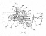
- FIGS. 1 and 2illustrate a surgical robot system 100 in accordance with an example.
- Surgical robot system 100may include, for example, a surgical robot 102, one or more robot arms 104, a base 106, a display 110, an end-effector 112, for example, including a guide tube 114, and one or more tracking markers 118.
- the surgical robot system 100may include a patient tracking device 116 also including one or more tracking markers 118, which is adapted to be secured directly to the patient 210 (e.g., to the bone of the patient 210).
- the surgical robot system 100may also utilize a camera 200, for example, positioned on a camera stand 202.
- the camera stand 202can have any suitable configuration to move, orient, and support the camera 200 in a desired position.
- the camera 200may include any suitable camera or cameras, such as one or more infrared cameras (e.g., bifocal or stereophotogrammetric cameras), able to identify, for example, active and passive tracking markers 118 in a given measurement volume viewable from the perspective of the camera 200.
- the camera 200may scan the given measurement volume and detect the light that comes from the markers 118 in order to identify and determine the position of the markers 118 in three-dimensions.
- active markers 118may include infrared-emitting markers that are activated by an electrical signal (e.g., infrared light emitting diodes (LEDs)), and passive markers 118 may include retro-reflective markers that reflect infrared light (e.g., they reflect incoming IR radiation into the direction of the incoming light), for example, emitted by illuminators on the camera 200 or other suitable device.
- LEDsinfrared light emitting diodes
- FIGS. 1 and 2illustrate a potential configuration for the placement of the surgical robot system 100 in an operating room environment.
- the robot 102may be positioned near or next to patient 210. Although depicted near the head of the patient 210, it will be appreciated that the robot 102 can be positioned at any suitable location near the patient 210 depending on the area of the patient 210 undergoing the operation.
- the camera 200may be separated from the robot system 100 and positioned at the foot of patient 210. This location allows the camera 200 to have a direct visual line of sight to the surgical field 208. Again, it is contemplated that the camera 200 may be located at any suitable position having line of sight to the surgical field 208.
- the surgeon 120may be positioned across from the robot 102, but is still able to manipulate the end-effector 112 and the display 110.
- a surgical assistant 126may be positioned across from the surgeon 120 again with access to both the end-effector 112 and the display 110. If desired, the locations of the surgeon 120 and the assistant 126 may be reversed. The traditional areas for the anesthesiologist 122 and the nurse or scrub tech 124 remain unimpeded by the locations of the robot 102 and camera 200.
- the display 110can be attached to the surgical robot 102 and in other examples, display 110 can be detached from surgical robot 102, either within a surgical room with the surgical robot 102, or in a remote location.
- End-effector 112may be coupled to the robot arm 104 and controlled by at least one motor.
- end-effector 112can comprise a guide tube 114, which is able to receive and orient a surgical instrument 608 (described further herein) used to perform surgery on the patient 210.
- end-effectoris used interchangeably with the terms “end-effectuator” and “effectuator element.”
- end-effector 112may be replaced with any suitable instrumentation suitable for use in surgery.
- end-effector 112can comprise any known structure for effecting the movement of the surgical instrument 608 in a desired manner.
- the surgical robot 102is able to control the translation and orientation of the end-effector 112.
- the robot 102is able to move end-effector 112 along x-, y-, and z-axes, for example.
- the end-effector 112can be configured for selective rotation about one or more of the x-, y-, and z-axis , and a Z Frame axis (such that one or more of the Euler Angles (e.g., roll, pitch, and/or yaw) associated with end-effector 112 can be selectively controlled).
- selective control of the translation and orientation of end-effector 112can permit performance of medical procedures with significantly improved accuracy compared to conventional robots that utilize, for example, a six degree of freedom robot arm comprising only rotational axes.
- the surgical robot system 100may be used to operate on patient 210, and robot arm 104 can be positioned above the body of patient 210, with end-effector 112 selectively angled relative to the z-axis toward the body of patient 210.
- the position of the surgical instrument 608can be dynamically updated so that surgical robot 102 can be aware of the location of the surgical instrument 608 at all times during the procedure. Consequently, in some examples, robot 102 can move the surgical instrument 608 to the desired position quickly without any further assistance from a physician (unless the physician so desires). In some further examples, surgical robot 102 can be configured to correct the path of the surgical instrument 608 if the surgical instrument 608 strays from the selected, preplanned trajectory. In some examples surgical robot 102 can be configured to permit stoppage, modification, and/or manual control of the movement of end-effector 112 and/or the surgical instrument 608.
- a physician or other usercan operate the system 100, and has the option to stop, modify, or manually control the autonomous movement of end-effector 112 and/or the surgical instrument 608.
- Further details of surgical robot system 100 including the control and movement of a surgical instrument 608 by surgical robot 102can be found in co-pending U.S. patent application Ser. No. 13/924,505 , with Publication No. 2013/0345718 .
- the robotic surgical system 100can comprise one or more tracking markers 118 configured to track the movement of robot arm 104, end-effector 112, patient 210, and/or the surgical instrument 608 in three dimensions.
- a plurality of tracking markers 118can be mounted (or otherwise secured) thereon to an outer surface of the robot 102, such as, for example and without limitation, on base 106 of robot 102, on robot arm 104, or on the end-effector 112.
- at least one tracking marker 118 of the plurality of tracking markers 118can be mounted or otherwise secured to the end-effector 112.
- One or more tracking markers 118can further be mounted (or otherwise secured) to the patient 210.
- the plurality of tracking markers 118can be positioned on the patient 210 spaced apart from the surgical field 208 to reduce the likelihood of being obscured by the surgeon, surgical tools, or other parts of the robot 102. Further, one or more tracking markers 118 can be further mounted (or otherwise secured) to the surgical tools 608 (e.g., a screw driver, dilator, implant inserter, or the like). Thus, the tracking markers 118 enable each of the marked objects (e.g., the end-effector 112, the patient 210, and the surgical tools 608) to be tracked by the robot 102.
- the marked objectse.g., the end-effector 112, the patient 210, and the surgical tools 608
- system 100can use tracking information collected from each of the marked objects to calculate the orientation and location, for example, of the end-effector 112, the surgical instrument 608 (e.g., positioned in the tube 114 of the end-effector 112), and the relative position of the patient 210.
- one or more of markers 118may be optical markers.
- the positioning of one or more tracking markers 118 on end-effector 112can maximize the accuracy of the positional measurements by serving to check or verify the position of end-effector 112. Further details of surgical robot system 100 including the control, movement and tracking of surgical robot 102 and of a surgical instrument 608 can be found in co-pending U.S. patent application Ser. No. 13/924,505 .
- markers 118coupled to the surgical instrument 608.
- these markers 118for example, coupled to the patient 210 and surgical instruments 608, as well as markers 118 coupled to the end-effector 112 of the robot 102 can comprise conventional infrared light-emitting diodes (LEDs) or an Optotrak® diode capable of being tracked using a commercially available infrared optical tracking system such as Optotrak®.
- Optotrak®is a registered trademark of Northern Digital Inc., Waterloo, Ontario, Canada.
- markers 118can comprise conventional reflective spheres capable of being tracked using a commercially available optical tracking system such as Polaris Spectra. Polaris Spectra is also a registered trademark of Northern Digital, Inc.
- the markers 118 coupled to the end-effector 112are active markers which comprise infrared light-emitting diodes which may be turned on and off, and the markers 118 coupled to the patient 210 and the surgical instruments 608 comprise passive reflective spheres.
- markers 118can comprise a radio-frequency and/or electromagnetic reflector or transceiver and the camera 200 can include or be replaced by a radio-frequency and/or electromagnetic transceiver.
- FIG. 3illustrates a surgical robot system 300 and camera stand 302, in a docked configuration, consistent with an example of the present disclosure.
- Surgical robot system 300may comprise a robot 301 including a display 304, upper arm 306, lower arm 308, end-effector 310, vertical column 312, casters 314, cabinet 316, tablet drawer 318, connector panel 320, control panel 322, and ring of information 324.
- Camera stand 302may comprise camera 326. These components are described in greater with respect to FIG. 5 .
- FIG. 3illustrates the surgical robot system 300 in a docked configuration where the camera stand 302 is nested with the robot 301, for example, when not in use. It will be appreciated by those skilled in the art that the camera 326 and robot 301 may be separated from one another and positioned at any appropriate location during the surgical procedure, for example, as shown in FIGS. 1 and 2 .
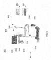
- FIG. 4illustrates a base 400 consistent with an example of the present disclosure.
- Base 400may be a portion of surgical robot system 300 and comprise cabinet 316.
- Cabinet 316may house certain components of surgical robot system 300 including but not limited to a battery 402, a power distribution module 404, a platform interface board module 406, a computer 408, a handle 412, and a tablet drawer 414. The connections and relationship between these components is described in greater detail with respect to FIG. 5 .
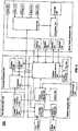
- FIG. 5illustrates a block diagram of certain components of an example of surgical robot system 300.
- Surgical robot system 300may comprise platform subsystem 502, computer subsystem 504, motion control subsystem 506, and tracking subsystem 532.
- Platform subsystem 502may further comprise battery 402, power distribution module 404, platform interface board module 406, and tablet charging station 534.
- Computer subsystem 504may further comprise computer 408, display 304, and speaker 536.
- Motion control subsystem 506may further comprise driver circuit 508, motors 510, 512, 514, 516, 518, stabilizers 520, 522, 524, 526, end-effector 310, and controller 538.
- Tracking subsystem 532may further comprise position sensor 540 and camera converter 542.
- System 300may also comprise a foot pedal 544 and tablet 546.
- Input poweris supplied to system 300 via a power source 548 which may be provided to power distribution module 404.
- Power distribution module 404receives input power and is configured to generate different power supply voltages that are provided to other modules, components, and subsystems of system 300.
- Power distribution module 404may be configured to provide different voltage supplies to platform interface module 406, which may be provided to other components such as computer 408, display 304, speaker 536, driver 508 to, for example, power motors 512, 514, 516, 518 and end-effector 310, motor 510, ring 324, camera converter 542, and other components for system 300 for example, fans for cooling the electrical components within cabinet 316.
- Power distribution module 404may also provide power to other components such as tablet charging station 534 that may be located within tablet drawer 318.
- Tablet charging station 534may be in wireless or wired communication with tablet 546 for charging table 546.
- Tablet 546may be used by a surgeon consistent with the present disclosure and described herein.
- Power distribution module 404may also be connected to battery 402, which serves as temporary power source in the event that power distribution module 404 does not receive power from input power 548. At other times, power distribution module 404 may serve to charge battery 402 if necessary.
- Connector panel 320may serve to connect different devices and components to system 300 and/or associated components and modules.
- Connector panel 320may contain one or more ports that receive lines or connections from different components.
- connector panel 320may have a ground terminal port that may ground system 300 to other equipment, a port to connect foot pedal 544 to system 300, a port to connect to tracking subsystem 532, which may comprise position sensor 540, camera converter 542, and cameras 326 associated with camera stand 302.
- Connector panel 320may also include other ports to allow USB, Ethernet, HDMI communications to other components, such as computer 408.
- Control panel 322may provide various buttons or indicators that control operation of system 300 and/or provide information regarding system 300.
- control panel 322may include buttons to power on or off system 300, lift or lower vertical column 312, and lift or lower stabilizers 520-526 that may be designed to engage casters 314 to lock system 300 from physically moving.
- Other buttonsmay stop system 300 in the event of an emergency, which may remove all motor power and apply mechanical brakes to stop all motion from occurring.
- Control panel 322may also have indicators notifying the user of certain system conditions such as a line power indicator or status of charge for battery 402.
- Ring 324may be a visual indicator to notify the user of system 300 of different modes that system 300 is operating under and certain warnings to the user.
- Computer subsystem 504includes computer 408, display 304, and speaker 536.
- Computer 504includes an operating system and software to operate system 300.
- Computer 504may receive and process information from other components (for example, tracking subsystem 532, platform subsystem 502, and/or motion control subsystem 506) in order to display information to the user.
- computer subsystem 504may also include speaker 536 to provide audio to the user.
- Tracking subsystem 532may include position sensor 504 and converter 542. Tracking subsystem 532 may correspond to camera stand 302 including camera 326 as described with respect to FIG. 3 . Position sensor 504 may be camera 326. Tracking subsystem may track the location of certain markers that are located on the different components of system 300 and/or instruments used by a user during a surgical procedure. This tracking may be conducted in a manner consistent with the present disclosure including the use of infrared technology that tracks the location of active or passive elements, such as LEDs or reflective markers, respectively. The location, orientation, and position of structures having these types of markers may be provided to computer 408 which may be shown to a user on display 304. For example, a surgical instrument 608 having these types of markers and tracked in this manner (which may be referred to as a navigational space) may be shown to a user in relation to a three dimensional image of a patient's anatomical structure.
- Motion control subsystem 506may be configured to physically move vertical column 312, upper arm 306, lower arm 308, or rotate end-effector 310.
- the physical movementmay be conducted through the use of one or more motors 510-518.
- motor 510may be configured to vertically lift or lower vertical column 312.
- Motor 512may be configured to laterally move upper arm 308 around a point of engagement with vertical column 312 as shown in FIG. 3 .
- Motor 514may be configured to laterally move lower arm 308 around a point of engagement with upper arm 308 as shown in FIG. 3 .
- Motors 516 and 518may be configured to move end-effector 310 in a manner such that one may control the roll and one may control the tilt, thereby providing multiple angles that end-effector 310 may be moved. These movements may be achieved by controller 538 which may control these movements through load cells disposed on end-effector 310 and activated by a user engaging these load cells to move system 300 in a desired manner.
- system 300may provide for automatic movement of vertical column 312, upper arm 306, and lower arm 308 through a user indicating on display 304 (which may be a touchscreen input device) the location of a surgical instrument or component on three dimensional image of the patient's anatomy on display 304.
- the usermay initiate this automatic movement by stepping on foot pedal 544 or some other input means.
- FIG. 6illustrates a surgical robot system 600 consistent with an example.
- Surgical robot system 600may comprise end-effector 602, robot arm 604, guide tube 606, instrument 608, and robot base 610.
- Instrument tool 608may be attached to a tracking array 612 including one or more tracking markers (such as markers 118) and have an associated trajectory 614.
- Trajectory 614may represent a path of movement that instrument tool 608 is configured to travel once it is positioned through or secured in guide tube 606, for example, a path of insertion of instrument tool 608 into a patient.
- robot base 610may be configured to be in electronic communication with robot arm 604 and end-effector 602 so that surgical robot system 600 may assist a user (for example, a surgeon) in operating on the patient 210.
- Surgical robot system 600may be consistent with previously described surgical robot system 100 and 300.
- a tracking array 612may be mounted on instrument 608 to monitor the location and orientation of instrument tool 608.
- the tracking array 612may be attached to an instrument 608 and may comprise tracking markers 804.
- tracking markers 804may be, for example, light emitting diodes and/or other types of reflective markers (e.g., markers 118 as described elsewhere herein).
- the tracking devicesmay be one or more line of sight devices associated with the surgical robot system.
- the tracking devicesmay be one or more cameras 200, 326 associated with the surgical robot system 100, 300 and may also track tracking array 612 for a defined domain or relative orientations of the instrument 608 in relation to the robot arm 604, the robot base 610, end-effector 602, and/or the patient 210.
- the tracking devicesmay be consistent with those structures described in connection with camera stand 302 and tracking subsystem 532.
- FIGS. 7A, 7B, and 7Cillustrate a top view, front view, and side view, respectively, of end-effector 602 consistent with an example.
- End-effector 602may comprise one or more tracking markers 702.
- Tracking markers 702may be light emitting diodes or other types of active and passive markers, such as tracking markers 118 that have been previously described.
- the tracking markers 702are active infrared-emitting markers that are activated by an electrical signal (e.g., infrared light emitting diodes (LEDs)).
- LEDsinfrared light emitting diodes
- tracking markers 702may be activated such that the infrared markers 702 are visible to the camera 200, 326 or may be deactivated such that the infrared markers 702 are not visible to the camera 200, 326.
- the end-effector 602may be controlled by the system 100, 300, 600, and when the markers 702 are deactivated, the end-effector 602 may be locked in position and unable to be moved by the system 100, 300, 600.
- Markers 702may be disposed on or within end-effector 602 in a manner such that the markers 702 are visible by one or more cameras 200, 326 or other tracking devices associated with the surgical robot system 100, 300, 600.
- the camera 200, 326 or other tracking devicesmay track end-effector 602 as it moves to different positions and viewing angles by following the movement of tracking markers 702.
- the location of markers 702 and/or end-effector 602may be shown on a display 110, 304 associated with the surgical robot system 100, 300, 600, for example, display 110 as shown in FIG. 2 and/or display 304 shown in FIG. 3 .
- This display 110, 304may allow a user to ensure that end-effector 602 is in a desirable position in relation to robot arm 604, robot base 610, the patient 210, and/or the user.
- markers 702may be placed around the surface of end-effector 602 so that a tracking device placed away from the surgical field 208 and facing toward the robot 102, 301 and the camera 200, 326 is able to view at least 3 of the markers 702 through a range of common orientations of the end-effector 602 relative to the tracking device 100, 300, 600.
- distribution of markers 702 in this wayallows end-effector 602 to be monitored by the tracking devices when end-effector 602 is translated and rotated in the surgical field 208.
- end-effector 602may be equipped with infrared (IR) receivers that can detect when an external camera 200, 326 is getting ready to read markers 702. Upon this detection, end-effector 602 may then illuminate markers 702.
- IRinfrared
- the detection by the IR receivers that the external camera200, 326 is ready to read markers 702may signal the need to synchronize a duty cycle of markers 702, which may be light emitting diodes, to an external camera200, 326. This may also allow for lower power consumption by the robotic system as a whole, whereby markers 702 would only be illuminated at the appropriate time instead of being illuminated continuously.
- markers 702may be powered off to prevent interference with other navigation tools, such as different types of surgical instruments 608.
- FIG. 8depicts one type of surgical instrument 608 including a tracking array 612 and tracking markers 804.
- Tracking markers 804may be of any type described herein including but not limited to light emitting diodes or reflective spheres. Markers 804 are monitored by tracking devices associated with the surgical robot system 100, 300, 600 and may be one or more of the line of sight cameras 200, 326. The cameras 200, 326 may track the location of instrument 608 based on the position and orientation of tracking array 612 and markers 804. A user, such as a surgeon 120, may orient instrument 608 in a manner so that tracking array 612 and markers 804 are sufficiently recognized by the tracking device or camera 200, 326 to display instrument 608 and markers 804 on, for example, display 110 of the exemplary surgical robot system.
- the manner in which a surgeon 120 may place instrument 608 into guide tube 606 of the end-effector 602 and adjust the instrument 608is evident in FIG. 8 .
- the hollow tube or guide tube 114, 606 of the end-effector 112, 310, 602is sized and configured to receive at least a portion of the surgical instrument 608.
- the guide tube 114, 606is configured to be oriented by the robot arm 104 such that insertion and trajectory for the surgical instrument 608 is able to reach a desired anatomical target within or upon the body of the patient 210.
- the surgical instrument 608may include at least a portion of a generally cylindrical instrument.
- the surgical instrument 608may include one or more of a guide wire, cannula, a retractor, a drill, a reamer, a screw driver, an insertion tool, a removal tool, or the like.
- the hollow tube 114, 606is generally shown as having a cylindrical configuration, it will be appreciated by those of skill in the art that the guide tube 114, 606 may have any suitable shape, size and configuration desired to accommodate the surgical instrument 608 and access the surgical site.
- FIGS. 9A-9Cillustrate end-effector 602 and a portion of robot arm 604 consistent with an example.
- End-effector 602may further comprise body 1202 and clamp 1204.
- Clamp 1204may comprise handle 1206, balls 1208, spring 1210, and lip 1212.
- Robot arm 604may further comprise depressions 1214, mounting plate 1216, lip 1218, and magnets 1220.
- End-effector 602may mechanically interface and/or engage with the surgical robot system and robot arm 604 through one or more couplings.
- end-effector 602may engage with robot arm 604 through a locating coupling and/or a reinforcing coupling. Through these couplings, end-effector 602 may fasten with robot arm 604 outside a flexible and sterile barrier.
- the locating couplingmay be a magnetically kinematic mount and the reinforcing coupling may be a five bar over center clamping linkage.
- robot arm 604may comprise mounting plate 1216, which may be non-magnetic material, one or more depressions 1214, lip 1218, and magnets 1220.
- Magnet 1220is mounted below each of depressions 1214.
- Portions of clamp 1204may comprise magnetic material and be attracted by one or more magnets 1220.
- balls 1208become seated into respective depressions 1214.
- balls 1208 as shown in FIG. 9Bwould be seated in depressions 1214 as shown in FIG. 9A .
- This seatingmay be considered a magnetically-assisted kinematic coupling.
- Magnets 1220may be configured to be strong enough to support the entire weight of end-effector 602 regardless of the orientation of end-effector 602.
- the locating couplingmay be any style of kinematic mount that uniquely restrains six degrees of freedom.
- portions of clamp 1204may be configured to be a fixed ground link and as such clamp 1204 may serve as a five bar linkage.
- Closing clamp handle 1206may fasten end-effector 602 to robot arm 604 as lip 1212 and lip 1218 engage clamp 1204 in a manner to secure end-effector 602 and robot arm 604.
- spring 1210may be stretched or stressed while clamp 1204 is in a locked position.
- the locked positionmay be a position that provides for linkage past center. Because of a closed position that is past center, the linkage will not open absent a force applied to clamp handle 1206 to release clamp 1204. Thus, in a locked position end-effector 602 may be robustly secured to robot arm 604.
- Spring 1210may be a curved beam in tension.
- Spring 1210may be comprised of a material that exhibits high stiffness and high yield strain such as virgin PEEK (poly-ether-ether-ketone).
- the linkage between end-effector 602 and robot arm 604may provide for a sterile barrier between end-effector 602 and robot arm 604 without impeding fastening of the two couplings.
- the reinforcing couplingmay be a linkage with multiple spring members.
- the reinforcing couplingmay latch with a cam or friction based mechanism.
- the reinforcing couplingmay also be a sufficiently powerful electromagnet that will support fastening end-effector 102 to robot arm 604.
- the reinforcing couplingmay be a multi-piece collar completely separate from either end-effector 602 and/or robot arm 604 that slips over an interface between end-effector 602 and robot arm 604 and tightens with a screw mechanism, an over center linkage, or a cam mechanism.
- a registration system 1400may be used as illustrated in FIG. 10 .
- a patient tracking device 116may include a patient fixation instrument 1402 to be secured to a rigid anatomical structure of the patient 210 and a dynamic reference base (DRB) 1404 may be securely attached to the patient fixation instrument 1402.
- DRBdynamic reference base
- patient fixation instrument 1402may be inserted into opening 1406 of dynamic reference base 1404.
- Dynamic reference base 1404may contain markers 1408 that are visible to tracking devices, such as tracking subsystem 532. These markers 1408 may be optical markers or reflective spheres, such as tracking markers 118, as previously discussed herein.
- Patient fixation instrument 1402is attached to a rigid anatomy of the patient 210 and may remain attached throughout the surgical procedure.
- patient fixation instrument 1402is attached to a rigid area of the patient 210, for example, a bone that is located away from the targeted anatomical structure subject to the surgical procedure.
- dynamic reference base 1404is associated with the targeted anatomical structure through the use of a registration fixture that is temporarily placed on or near the targeted anatomical structure in order to register the dynamic reference base 1404 with the location of the targeted anatomical structure.
- a registration fixture 1410is attached to patient fixation instrument 1402 through the use of a pivot arm 1412.
- Pivot arm 1412is attached to patient fixation instrument 1402 by inserting patient fixation instrument 1402 through an opening 1414 of registration fixture 1410.
- Pivot arm 1412is attached to registration fixture 1410 by, for example, inserting a knob 1416 through an opening 1418 of pivot arm 1412.
- registration fixture 1410may be placed over the targeted anatomical structure and its location may be determined in an image space and navigation space using tracking markers 1420 and/or fiducials 1422 on registration fixture 1410.
- Registration fixture 1410may contain a collection of markers 1420 that are visible in a navigational space (for example, markers 1420 may be detectable by tracking subsystem 532).
- Tracking markers 1420may be optical markers visible in infrared light as previously described herein.
- Registration fixture 1410may also contain a collection of fiducials 1422, for example, such as bearing balls, that are visible in an imaging space (for example, a three dimension CT image). As described in greater detail with respect to FIG.
- the targeted anatomical structuremay be associated with dynamic reference base 1404 thereby allowing depictions of objects in the navigational space to be overlaid on images of the anatomical structure.
- Dynamic reference base 1404located at a position away from the targeted anatomical structure, may become a reference point thereby allowing removal of registration fixture 1410 and/or pivot arm 1412 from the surgical area.
- FIG. 11provides an exemplary method 1500 for registration consistent with the present disclosure.
- Method 1500begins at step 1502 wherein a graphical representation (or image(s)) of the targeted anatomical structure may be imported into system 100, 300 600, for example computer 408.
- the graphical representationmay be three dimensional CT or a fluoroscope scan of the targeted anatomical structure of the patient 210 which includes registration fixture 1410 and a detectable imaging pattern of fiducials 1420.
- an imaging pattern of fiducials 1420is detected and registered in the imaging space and stored in computer 408.
- a graphical representation of the registration fixture 1410may be overlaid on the images of the targeted anatomical structure.
- a navigational pattern of registration fixture 1410is detected and registered by recognizing markers 1420.
- Markers 1420may be optical markers that are recognized in the navigation space through infrared light by tracking subsystem 532 via position sensor 540.
- registration fixture 1410may be recognized in both the image space through the use of fiducials 1422 and the navigation space through the use of markers 1420.
- the registration of registration fixture 1410 in the image spaceis transferred to the navigation space. This transferal is done, for example, by using the relative position of the imaging pattern of fiducials 1422 compared to the position of the navigation pattern of markers 1420.
- registration of the navigation space of registration fixture 1410(having been registered with the image space) is further transferred to the navigation space of dynamic registration array 1404 attached to patient fixture instrument 1402.
- registration fixture 1410may be removed and dynamic reference base 1404 may be used to track the targeted anatomical structure in both the navigation and image space because the navigation space is associated with the image space.
- the navigation spacemay be overlaid on the image space and objects with markers visible in the navigation space (for example, surgical instruments 608 with optical markers 804).
- the objectsmay be tracked through graphical representations of the surgical instrument 608 on the images of the targeted anatomical structure.
- FIGS. 12A-12Billustrate imaging devices 1304 that may be used in conjunction with robot systems 100, 300, 600 to acquire pre-operative, intra-operative, post-operative, and/or real-time image data of patient 210. Any appropriate subject matter may be imaged for any appropriate procedure using the imaging system 1304.
- the imaging system 1304may be any imaging device such as imaging device 1306 and/or a C-arm 1308 device. It may be desirable to take x-rays of patient 210 from a number of different positions, without the need for frequent manual repositioning of patient 210 which may be required in an x-ray system.
- the imaging system 1304may be in the form of a C-arm 1308 that includes an elongated C-shaped member terminating in opposing distal ends 1312 of the "C" shape.
- C-shaped member 1130may further comprise an x-ray source 1314 and an image receptor 1316.
- the space within C-arm 1308 of the armmay provide room for the physician to attend to the patient substantially free of interference from x-ray support structure 1318.
- the imaging systemmay include imaging device 1306 having a gantry housing 1324 attached to a support structure imaging device support structure 1328, such as a wheeled mobile cart 1330 with wheels 1332, which may enclose an image capturing portion, not illustrated.
- the image capturing portionmay include an x-ray source and/or emission portion and an x-ray receiving and/or image receiving portion, which may be disposed about one hundred and eighty degrees from each other and mounted on a rotor (not illustrated) relative to a track of the image capturing portion.
- the image capturing portionmay be operable to rotate three hundred and sixty degrees during image acquisition.
- the image capturing portionmay rotate around a central point and/or axis, allowing image data of patient 210 to be acquired from multiple directions or in multiple planes.
- the surgical robot system 100, 300, 600relies on accurate positioning of the end-effector 112, 602, surgical instruments 608, and/or the patient 210 (e.g., patient tracking device 116) relative to the desired surgical area.
- the tracking markers 118, 804are rigidly attached to a portion of the instrument 608 and/or end-effector 112.
- FIG. 13Adepicts part of the surgical robot system 100 with the robot 102 including base 106, robot arm 104, and end-effector 112.
- the other elements, not illustrated, such as the display, cameras, etc.may also be present as described herein.
- FIG. 13Bdepicts a close-up view of the end-effector 112 with guide tube 114 and a plurality of tracking markers 118 rigidly affixed to the end-effector 112.
- the plurality of tracking markers 118are attached to the guide tube 112.
- FIG. 13Cdepicts an instrument 608 (in this case, a probe 608A) with a plurality of tracking markers 804 rigidly affixed to the instrument 608.
- the instrument 608could include any suitable surgical instrument, such as, but not limited to, guide wire, cannula, a retractor, a drill, a reamer, a screw driver, an insertion tool, a removal tool, or the like.
- an array of tracking markers 118, 804may be rigidly attached to a portion of the tool 608 or end-effector 112.
- the tracking markers 118, 804are attached such that the markers 118, 804 are out of the way (e.g., not impeding the surgical operation, visibility, etc.).
- the markers 118, 804may be affixed to the instrument 608, end-effector 112, or other object to be tracked, for example, with an array 612.
- the array 612may include a linear section, a cross piece, and may be asymmetric such that the markers 118, 804 are at different relative positions and locations with respect to one another.
- FIG. 13Ca probe 608A with a 4-marker tracking array 612 is shown, and FIG. 13B depicts the end-effector 112 with a different 4-marker tracking array 612.
- the tracking array 612functions as the handle 620 of the probe 608A.
- the four markers 804are attached to the handle 620 of the probe 608A, which is out of the way of the shaft 622 and tip 624. Stereophotogrammetric tracking of these four markers 804 allows the instrument 608 to be tracked as a rigid body and for the tracking system 100, 300, 600 to precisely determine the position of the tip 624 and the orientation of the shaft 622 while the probe 608A is moved around in front of tracking cameras 200, 326.
- the markers 118, 804 on each tool 608, end-effector 112, or the likeare arranged asymmetrically with a known inter-marker spacing.
- the reason for asymmetric alignmentis so that it is unambiguous which marker 118, 804 corresponds to a particular location on the rigid body and whether markers 118, 804 are being viewed from the front or back, i.e., mirrored.
- each array 612 and thus each tool 608, end-effector 112, or other object to be trackedshould have a unique marker pattern to allow it to be distinguished from other tools 608 or other objects being tracked.
- Asymmetry and unique marker patternsallow the system 100, 300, 600 to detect individual markers 118, 804 then to check the marker spacing against a stored template to determine which tool 608, end effector 112, or other object they represent. Detected markers 118, 804 can then be sorted automatically and assigned to each tracked object in the correct order. Without this information, rigid body calculations could not then be performed to extract key geometric information, for example, such as tool tip 624 and alignment of the shaft 622, unless the user manually specified which detected marker 118, 804 corresponded to which position on each rigid body. These concepts are commonly known to those skilled in the methods of 3D optical tracking.
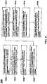
- FIGS. 14A-14Dan alternative version of an end-effector 912 with moveable tracking markers 918A-918D is shown.
- FIG. 14Aan array with moveable tracking markers 918A-918D are shown in a first configuration
- FIG. 14Bthe moveable tracking markers 918A-918D are shown in a second configuration, which is angled relative to the first configuration.
- FIG. 14Cshows the template of the tracking markers 918A-918D, for example, as seen by the cameras 200, 326 in the first configuration of FIG. 14A
- FIG. 14Dshows the template of tracking markers 918A-918D, for example, as seen by the cameras 200, 326 in the second configuration of FIG. 14B .
- 4-marker array trackingis contemplated wherein the markers 918A-918D are not all in fixed position relative to the rigid body and instead, one or more of the array markers 918A-918D can be adjusted, for example, during testing, to give updated information about the rigid body that is being tracked without disrupting the process for automatic detection and sorting of the tracked markers 918A-918D.
- the tracking array's primary purposeis to update the position of the end effector 912 in the camera coordinate system.
- the array 612 of reflective markers 118rigidly extend from the guide tube 114. Because the tracking markers 118 are rigidly connected, knowledge of the marker locations in the camera coordinate system also provides exact location of the centerline, tip, and tail of the guide tube 114 in the camera coordinate system.
- information about the position of the end effector 112 from such an array 612 and information about the location of a target trajectory from another tracked sourceare used to calculate the required moves that must be input for each axis of the robot 102 that will move the guide tube 114 into alignment with the trajectory and move the tip to a particular location along the trajectory vector.
- the desired trajectoryis in an awkward or unreachable location, but if the guide tube 114 could be swiveled, it could be reached.
- a very steep trajectory pointing away from the base 106 of the robot 102might be reachable if the guide tube 114 could be swiveled upward beyond the limit of the pitch (wrist up-down angle) axis, but might not be reachable if the guide tube 114 is attached parallel to the plate connecting it to the end of the wrist.
- the base 106 of the robot 102might be moved or a different end effector 112 with a different guide tube attachment might be exchanged with the working end effector. Both of these solutions may be time consuming and cumbersome.
- the robot 102can provide updated information about the object being tracked without disrupting the detection and tracking process.
- one of the markers 918A-918Dmay be fixed in position and the other markers 918A-918D may be moveable; two of the markers 918A-918D may be fixed in position and the other markers 918A-918D may be moveable; three of the markers 918A-918D may be fixed in position and the other marker 918A-918D may be moveable; or all of the markers 918A-918D may be moveable.
- markers 918A, 918 Bare rigidly connected directly to a base 906 of the end-effector 912, and markers 918C, 918D are rigidly connected to the tube 914.
- array 908may be provided to attach the markers 918A-918D to the end-effector 912, instrument 608, or other object to be tracked.
- the array 908is comprised of a plurality of separate components.
- markers 918A, 918Bmay be connected to the base 906 with a first array 908A
- markers 918C, 918Dmay be connected to the guide tube 914 with a second array 908B.
- Marker 918Amay be affixed to a first end of the first array 908A and marker 918B may be separated a linear distance and affixed to a second end of the first array 908A. While first array 908 is substantially linear, second array 908B has a bent or V-shaped configuration, with respective root ends, connected to the guide tube 914, and diverging therefrom to distal ends in a V-shape with marker 918C at one distal end and marker 918D at the other distal end.
- specific configurationsare exemplified herein, it will be appreciated that other asymmetric designs including different numbers and types of arrays 908A, 908B and different arrangements, numbers, and types of markers 918A-918D are contemplated.
- the guide tube 914may be moveable, swivelable, or pivotable relative to the base 906, for example, across a hinge 920 or other connector to the base 906.
- markers 918C, 918Dare moveable such that when the guide tube 914 pivots, swivels, or moves, markers 918C, 918D also pivot, swivel, or move.
- guide tube 914has a longitudinal axis 916 which is aligned in a substantially normal or vertical orientation such that markers 918A-918D have a first configuration.
- FIG. 14Bthe guide tube 914 is pivoted, swiveled, or moved such that the longitudinal axis 916 is now angled relative to the vertical orientation such that markers 918A-918D have a second configuration, different from the first configuration.
- the robotic system 100, 300, 600would not be able to automatically detect that the guide tube 914 orientation had changed.
- the robotic system 100, 300, 600would track the positions of the marker array 908 and would calculate incorrect robot axis moves assuming the guide tube 914 was attached to the wrist (the robot arm 104) in the previous orientation.
- markers 918A-918De.g., two markers 918C, 918D
- markers 918A-918De.g., two markers 918A, 918B
- markers 918A-918Dare configured to be moved, pivoted, swiveled, or the like according to any suitable means.
- the markers 918A-918Dmay be moved by a hinge 920, such as a clamp, spring, lever, slide, toggle, or the like, or any other suitable mechanism for moving the markers 918A-918D individually or in combination, moving the arrays 908A, 908B individually or in combination, moving any portion of the end-effector 912 relative to another portion, or moving any portion of the tool 608 relative to another portion.
- the array 908 and guide tube 914may become reconfigurable by simply loosening the clamp or hinge 920, moving part of the array 908A, 908B relative to the other part 908A, 908B, and retightening the hinge 920 such that the guide tube 914 is oriented in a different position.
- two markers 918C, 918Dmay be rigidly interconnected with the tube 914 and two markers 918A, 918B may be rigidly interconnected across the hinge 920 to the base 906 of the end-effector 912 that attaches to the robot arm 104.
- the hinge 920may be in the form of a clamp, such as a wing nut or the like, which can be loosened and retightened to allow the user to quickly switch between the first configuration ( FIG. 14A ) and the second configuration ( FIG. 14B ).
- the cameras 200, 326detect the markers 918A-918D, for example, in one of the templates identified in FIGS. 14C and 14D . If the array 908 is in the first configuration ( FIG. 14A ) and tracking cameras 200, 326 detect the markers 918A-918D, then the tracked markers match Array Template 1 as shown in FIG. 14C . If the array 908 is the second configuration ( FIG. 14B ) and tracking cameras 200, 326 detect the same markers 918A-918D, then the tracked markers match Array Template 2 as shown in FIG. 14D .
- Array Template 1 and Array Template 2are recognized by the system 100, 300, 600 as two distinct tools, each with its own uniquely defined spatial relationship between guide tube 914, markers 918A-918D, and robot attachment. The user could therefore adjust the position of the end-effector 912 between the first and second configurations without notifying the system 100, 300, 600 of the change and the system 100, 300, 600 would appropriately adjust the movements of the robot 102 to stay on trajectory.
- the marker arraymatches unique templates that allow the system 100, 300, 600 to recognize the assembly as two different tools or two different end effectors.
- any position of the swivel between or outside of these two positionsnamely, Array Template 1 and Array Template 2 shown in FIGS. 14C and 14D , respectively
- the markers 918A-918Dwould not match any template and the system 100, 300, 600 would not detect any array present despite individual markers 918A-918D being detected by cameras 200, 326, with the result being the same as if the markers 918A-918D were temporarily blocked from view of the cameras 200, 326.
- other array templatesmay exist for other configurations, for example, identifying different instruments 608 or other end-effectors 112, 912, etc.
- FIGS. 14A and 14Btwo discrete assembly positions are shown in FIGS. 14A and 14B . It will be appreciated, however, that there could be multiple discrete positions on a swivel joint, linear joint, combination of swivel and linear joints, pegboard, or other assembly where unique marker templates may be created by adjusting the position of one or more markers 918A-918D of the array relative to the others, with each discrete position matching a particular template and defining a unique tool 608 or end-effector 112, 912 with different known attributes.
- end effector 912it will be appreciated that moveable and fixed markers 918A-918D may be used with any suitable instrument 608 or other object to be tracked.
- an external 3D tracking system 100, 300, 600When using an external 3D tracking system 100, 300, 600 to track a full rigid body array of three or more markers attached to a robot's end effector 112 (for example, as depicted in FIGS. 13A and 13B ), it is possible to directly track or to calculate the 3D position of every section of the robot 102 in the coordinate system of the cameras 200, 326.
- the geometric orientations of joints relative to the trackerare known by design, and the linear or angular positions of joints are known from encoders for each motor of the robot 102, fully defining the 3D positions of all of the moving parts from the end effector 112 to the base 116.
- a trackerwere mounted on the base 106 of the robot 102 (not shown), it is likewise possible to track or calculate the 3D position of every section of the robot 102 from base 106 to end effector 112 based on known joint geometry and joint positions from each motor's encoder.
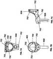
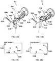
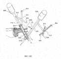
- End-effector 1012may be similar to the other end-effectors described herein, and may include a guide tube 1014 extending along a longitudinal axis 1016.
- a single tracking marker 1018similar to the other tracking markers described herein, may be rigidly affixed to the guide tube 1014. This single marker 1018 can serve the purpose of adding missing degrees of freedom to allow full rigid body tracking and/or can serve the purpose of acting as a surveillance marker to ensure that assumptions about robot and camera positioning are valid.
- the single tracking marker 1018may be attached to the robotic end effector 1012 as a rigid extension to the end effector 1012 that protrudes in any convenient direction and does not obstruct the surgeon's view.
- the tracking marker 1018may be affixed to the guide tube 1014 or any other suitable location of on the end-effector 1012. When affixed to the guide tube 1014, the tracking marker 1018 may be positioned at a location between first and second ends of the guide tube 1014.
- the single tracking marker 1018is shown as a reflective sphere mounted on the end of a narrow shaft 1017 that extends forward from the guide tube 1014 and is positioned longitudinally above a midpoint of the guide tube 1014 and below the entry of the guide tube 1014.
- This positionallows the marker 1018 to be generally visible by cameras 200, 326 but also would not obstruct vision of the surgeon 120 or collide with other tools or objects in the vicinity of surgery.
- the guide tube 1014 with the marker 1018 in this positionis designed for the marker array on any tool 608 introduced into the guide tube 1014 to be visible at the same time as the single marker 1018 on the guide tube 1014 is visible.
- the instrument 608becomes mechanically constrained in 4 of 6 degrees of freedom. That is, the instrument 608 cannot be rotated in any direction except about the longitudinal axis 1016 of the guide tube 1014 and the instrument 608 cannot be translated in any direction except along the longitudinal axis 1016 of the guide tube 1014. In other words, the instrument 608 can only be translated along and rotated about the centerline of the guide tube 1014. If two more parameters are known, such as (1) an angle of rotation about the longitudinal axis 1016 of the guide tube 1014; and (2) a position along the guide tube 1014, then the position of the end effector 1012 in the camera coordinate system becomes fully defined.
- the system 100, 300, 600should be able to know when a tool 608 is actually positioned inside of the guide tube 1014 and is not instead outside of the guide tube 1014 and just somewhere in view of the cameras 200, 326.
- the tool 608has a longitudinal axis or centerline 616 and an array 612 with a plurality of tracked markers 804.
- the rigid body calculationsmay be used to determine where the centerline 616 of the tool 608 is located in the camera coordinate system based on the tracked position of the array 612 on the tool 608.
- the fixed normal (perpendicular) distance D F from the single marker 1018 to the centerline or longitudinal axis 1016 of the guide tube 1014is fixed and is known geometrically, and the position of the single marker 1018 can be tracked. Therefore, when a detected distance D D from tool centerline 616 to single marker 1018 matches the known fixed distance D F from the guide tube centerline 1016 to the single marker 1018, it can be determined that the tool 608 is either within the guide tube 1014 (centerlines 616, 1016 of tool 608 and guide tube 1014 coincident) or happens to be at some point in the locus of possible positions where this distance D D matches the fixed distance D F . For example, in FIG.
- the normal detected distance D D from tool centerline 616 to the single marker 1018matches the fixed distance D F from guide tube centerline 1016 to the single marker 1018 in both frames of data (tracked marker coordinates) represented by the transparent tool 608 in two positions, and thus, additional considerations may be needed to determine when the tool 608 is located in the guide tube 1014.
- programmed logiccan be used to look for frames of tracking data in which the detected distance D D from tool centerline 616 to single marker 1018 remains fixed at the correct length despite the tool 608 moving in space by more than some minimum distance relative to the single sphere 1018 to satisfy the condition that the tool 608 is moving within the guide tube 1014.
- a first frame F1may be detected with the tool 608 in a first position and a second frame F2 may be detected with the tool 608 in a second position (namely, moved linearly with respect to the first position).
- the markers 804 on the tool array 612may move by more than a given amount (e.g., more than 5mm total) from the first frame F1 to the second frame F2. Even with this movement, the detected distance D D from the tool centerline vector C' to the single marker 1018 is substantially identical in both the first frame F1 and the second frame F2.
- the surgeon 120 or usercould place the tool 608 within the guide tube 1014 and slightly rotate it or slide it down into the guide tube 1014 and the system 100, 300, 600 would be able to detect that the tool 608 is within the guide tube 1014 from tracking of the five markers (four markers 804 on tool 608 plus single marker 1018 on guide tube 1014). Knowing that the tool 608 is within the guide tube 1014, all 6 degrees of freedom may be calculated that define the position and orientation of the robotic end effector 1012 in space.
- the centerline vector C' of the guide tube 1014 and tool 608 and the normal vector through the single marker 1018 and through the centerline vector C'has an orientation that is in a known orientation relative to the forearm of the robot distal to the wrist (in this example, oriented parallel to that segment) and intersects the centerline vector C' at a specific fixed position.
- three mutually orthogonal vectors k', j', i'can be constructed, as shown in FIG. 15E , defining rigid body position and orientation of the guide tube 1014.
- One of the three mutually orthogonal vectors k'is constructed from the centerline vector C'
- the second vector j'is constructed from the normal vector through the single marker 1018
- the third vector i'is the vector cross product of the first and second vectors k', j'.
- the robot's joint positions relative to these vectors k', j', i'are known and fixed when all joints are at zero, and therefore rigid body calculations can be used to determine the location of any section of the robot relative to these vectors k', j', i' when the robot is at a home position.
- the end effector guide tube 1014may be oriented in a particular position about its axis 1016 to allow machining or implant positioning.
- the orientation of anything attached to the tool 608 inserted into the guide tube 1014is known from the tracked markers 804 on the tool 608, the rotational orientation of the guide tube 1014 itself in the camera coordinate system is unknown without the additional tracking marker 1018 (or multiple tracking markers in other examples) on the guide tube 1014.
- This marker 1018provides essentially a "clock position" from -180° to +180° based on the orientation of the marker 1018 relative to the centerline vector C'.
- the single marker 1018can provide additional degrees of freedom to allow full rigid body tracking and/or can act as a surveillance marker to ensure that assumptions about the robot and camera positioning are valid.
- FIG. 16is a block diagram of a method 1100 for navigating and moving the end-effector 1012 (or any other end-effector described herein) of the robot 102 to a desired target trajectory. Another use of the single marker 1018 on the robotic end effector 1012 or guide tube 1014 is as part of the method 1100 enabling the automated safe movement of the robot 102 without a full tracking array attached to the robot 102.
- This method 1100functions when the tracking cameras 200, 326 do not move relative to the robot 102 (i.e., they are in a fixed position), the tracking system's coordinate system and robot's coordinate system are co-registered, and the robot 102 is calibrated such that the position and orientation of the guide tube 1014 can be accurately determined in the robot's Cartesian coordinate system based only on the encoded positions of each robotic axis.
- this coordinate transformationcan be a 4x4 matrix of translations and rotations that is well known in the field of robotics. This transformation will be termed Tcr to refer to "transformation - camera to robot". Once this transformation is known, any new frame of tracking data, which is received as x,y,z coordinates in vector form for each tracked marker, can be multiplied by the 4x4 matrix and the resulting x,y,z coordinates will be in the robot's coordinate system.
- a full tracking array on the robotis tracked while it is rigidly attached to the robot at a location that is known in the robot's coordinate system, then known rigid body methods are used to calculate the transformation of coordinates. It should be evident that any tool 608 inserted into the guide tube 1014 of the robot 102 can provide the same rigid body information as a rigidly attached array when the additional marker 1018 is also read. That is, the tool 608 need only be inserted to any position within the guide tube 1014 and at any rotation within the guide tube 1014, not to a fixed position and orientation.
- Tcrit is possible to determine Tcr by inserting any tool 608 with a tracking array 612 into the guide tube 1014 and reading the tool's array 612 plus the single marker 1018 of the guide tube 1014 while at the same time determining from the encoders on each axis the current location of the guide tube 1014 in the robot's coordinate system.
- Logic for navigating and moving the robot 102 to a target trajectoryis provided in the method 1100 of FIG. 16 .
- Tcrwas previously stored.
- step 1104after the robot base 106 is secured, greater than or equal to one frame of tracking data of a tool inserted in the guide tube while the robot is static is stored; and in step 1106, the transformation of robot guide tube position from camera coordinates to robot coordinates Tcr is calculated from this static data and previous calibration data. Tcr should remain valid as long as the cameras 200, 326 do not move relative to the robot 102.
- the system 100, 300, 600can be made to prompt the user to insert a tool 608 into the guide tube 1014 and then automatically perform the necessary calculations.
- each frame of data collectedconsists of the tracked position of the DRB 1404 on the patient 210, the tracked position of the single marker 1018 on the end effector 1014, and a snapshot of the positions of each robotic axis. From the positions of the robot's axes, the location of the single marker 1018 on the end effector 1012 is calculated. This calculated position is compared to the actual position of the marker 1018 as recorded from the tracking system. If the values agree, it can be assured that the robot 102 is in a known location.
- the transformation Tcris applied to the tracked position of the DRB 1404 so that the target for the robot 102 can be provided in terms of the robot's coordinate system. The robot 102 can then be commanded to move to reach the target.
- loop 1102includes step 1108 receiving rigid body information for DRB 1404 from the tracking system; step 1110 transforming target tip and trajectory from image coordinates to tracking system coordinates; and step 1112 transforming target tip and trajectory from camera coordinates to robot coordinates (apply Tcr). Loop 1102 further includes step 1114 receiving a single stray marker position for robot from tracking system; and step 1116 transforming the single stray marker from tracking system coordinates to robot coordinates (apply stored Tcr). Loop 1102 also includes step 1118 determining current location of the single robot marker 1018 in the robot coordinate system from forward kinematics.
- step 1120determines whether the stray marker coordinates from transformed tracked position agree with the calculated coordinates being less than a given tolerance. If yes, proceed to step 1122, calculate and apply robot move to target x, y, z and trajectory. If no, proceed to step 1124, halt and require full array insertion into guide tube 1014 before proceeding; step 1126 after array is inserted, recalculate Tcr; and then proceed to repeat steps 1108, 1114, and 1118.
- This method 1100has advantages over a method in which the continuous monitoring of the single marker 1018 to verify the location is omitted. Without the single marker 1018, it would still be possible to determine the position of the end effector 1012 using Tcr and to send the end-effector 1012 to a target location but it would not be possible to verify that the robot 102 was actually in the expected location. For example, if the cameras 200, 326 had been bumped and Tcr was no longer valid, the robot 102 would move to an erroneous location. For this reason, the single marker 1018 provides value with regard to safety.
- the term "surveillance marker”may be used, for example, in reference to a single marker that is in a fixed location relative to the DRB 1404. In this instance, if the DRB 1404 is bumped or otherwise dislodged, the relative location of the surveillance marker changes and the surgeon 120 can be alerted that there may be a problem with navigation. Similarly, in the examples described herein, with a single marker 1018 on the robot's guide tube 1014, the system 100, 300, 600 can continuously check whether the cameras 200, 326 have moved relative to the robot 102.
- this single marker 1018can also be thought of as a surveillance marker for the robot 102.
- instruments 608, such as implant holders 608B, 608Care depicted which include both fixed and moveable tracking markers 804, 806.
- the implant holders 608B, 608Cmay have a handle 620 and an outer shaft 622 extending from the handle 620.
- the shaft 622may be positioned substantially perpendicular to the handle 620, as shown, or in any other suitable orientation.
- An inner shaft 626may extend through the outer shaft 622 with a knob 628 at one end.
- Implant 10, 12connects to the shaft 622, at the other end, at tip 624 of the implant holder 608B, 608C using typical connection mechanisms known to those of skill in the art.
- the knob 628may be rotated, for example, to expand or articulate the implant 10, 12.
- U.S. Patent Nos. 8,709,086 and 8,491,659describe expandable fusion devices and methods of installation.
- the tracking array 612may contain a combination of fixed markers 804 and one or more moveable markers 806 which make up the array 612 or is otherwise attached to the implant holder 608B, 608C.
- the navigation array 612may include at least one or more (e.g., at least two) fixed position markers 804, which are positioned with a known location relative to the implant holder instrument 608B, 608C. These fixed markers 804 would not be able to move in any orientation relative to the instrument geometry and would be useful in defining where the instrument 608 is in space.
- At least one marker 806is present which can be attached to the array 612 or the instrument itself which is capable of moving within a pre-determined boundary (e.g., sliding, rotating, etc.) relative to the fixed markers 804.
- the system 100, 300, 600e.g., the software
- the system and/or the usercan determine the height or angle of the implant 10, 12 based on the location of the moveable marker 806.
- FIGS. 17A-17Bfour fixed markers 804 are used to define the implant holder 608B and a fifth moveable marker 806 is able to slide within a pre-determined path to provide feedback on the implant height (e.g., a contracted position or an expanded position).
- FIG. 17Ashows the expandable spacer 10 at its initial height
- FIG. 17Bshows the spacer 10 in the expanded state with the moveable marker 806 translated to a different position.
- the moveable marker 806moves closer to the fixed markers 804 when the implant 10 is expanded, although it is contemplated that this movement may be reversed or otherwise different.
- the amount of linear translation of the marker 806would correspond to the height of the implant 10. Although only two positions are shown, it would be possible to have this as a continuous function whereby any given expansion height could be correlated to a specific position of the moveable marker 806.
- FIGS. 18A-18Bfour fixed markers 804 are used to define the implant holder 608C and a fifth, moveable marker 806 is configured to slide within a pre-determined path to provide feedback on the implant articulation angle.
- FIG. 18Ashows the articulating spacer 12 at its initial linear state
- FIG. 18Bshows the spacer 12 in an articulated state at some offset angle with the moveable marker 806 translated to a different position.
- the amount of linear translation of the marker 806would correspond to the articulation angle of the implant 12. Although only two positions are shown, it would be possible to have this as a continuous function whereby any given articulation angle could be correlated to a specific position of the moveable marker 806.
- the moveable marker 806slides continuously to provide feedback about an attribute of the implant 10, 12 based on position. It is also contemplated that there may be discreet positions that the moveable marker 806 must be in which would also be able to provide further information about an implant attribute. In this case, each discreet configuration of all markers 804, 806 correlates to a specific geometry of the implant holder 608B, 608C and the implant 10, 12 in a specific orientation or at a specific height. In addition, any motion of the moveable marker 806 could be used for other variable attributes of any other type of navigated implant.
- the moveable marker 806should not be limited to just sliding as there may be applications where rotation of the marker 806 or other movements could be useful to provide information about the implant 10, 12. Any relative change in position between the set of fixed markers 804 and the moveable marker 806 could be relevant information for the implant 10, 12 or other device.
- the instrument 608could work with other medical devices and materials, such as spacers, cages, plates, fasteners, nails, screws, rods, pins, wire structures, sutures, anchor clips, staples, stents, bone grafts, biologics, or the like.
Landscapes
- Health & Medical Sciences (AREA)
- Life Sciences & Earth Sciences (AREA)
- Surgery (AREA)
- Engineering & Computer Science (AREA)
- Veterinary Medicine (AREA)
- General Health & Medical Sciences (AREA)
- Public Health (AREA)
- Biomedical Technology (AREA)
- Heart & Thoracic Surgery (AREA)
- Medical Informatics (AREA)
- Molecular Biology (AREA)
- Animal Behavior & Ethology (AREA)
- Nuclear Medicine, Radiotherapy & Molecular Imaging (AREA)
- Robotics (AREA)
- Pathology (AREA)
- Physics & Mathematics (AREA)
- Oral & Maxillofacial Surgery (AREA)
- Biophysics (AREA)
- Human Computer Interaction (AREA)
- Electromagnetism (AREA)
- Manipulator (AREA)
Description
- The present disclosure relates to position recognition systems, and in particular, end-effector and tool tracking and manipulation during a robot assisted surgery.
- Position recognition systems are used to determine the position of and track a particular object in 3-dimensions (3D). In robot assisted surgeries, for example, certain objects, such as surgical instruments, need to be tracked with a high degree of precision as the instrument is being positioned and moved by a robot or by a physician, for example.
- Infrared signal based position recognition systems may use passive and/or active sensors or markers for tracking the objects. In passive sensors or markers, objects to be tracked may include passive sensors, such as reflective spherical balls, which are positioned at strategic locations on the object to be tracked. Infrared transmitters transmit a signal, and the reflective spherical balls reflect the signal to aid in determining the position of the object in 3D. In active sensors or markers, the objects to be tracked include active infrared transmitters, such as light emitting diodes (LEDs), and thus generate their own infrared signals for 3D detection.
- With either active or passive tracking sensors, the system then geometrically resolves the 3-dimensional position of the active and/or passive sensors based on information from or with respect to one or more of the infrared cameras, digital signals, known locations of the active or passive sensors, distance, the time it took to receive the responsive signals, other known variables, or a combination thereof.
- One problem is that the tracking sensors are typically rigidly attached to a portion of the object to be tracked and is typically not moveable on the object itself. Also, the systems typically require a plurality of markers, often four markers, to accurately determine the location of the object. Therefore, there is a need to provide improved systems and methods for recognizing the 3-dimensional position of an object, which is accurate, but may be moveable and/or provided with fewer sensors or markers, for example, to provide additional information about the object or its position.
US 2015/196365 discloses a surgical instrument guide for use with a surgical robot system, said guide being attached to or part of an end effector.US 2014/275955 discloses a surgical robot system with a guide tube attached to an end effector, and marker arrays for navigation.US 2009/099445 discloses replaceable marker arrangements allowing a surgical instrument to be tracked.- To meet this and other needs, devices, systems, and methods for determining the 3-dimensional position of an object for use with robot-assisted surgeries is provided.
- Disclosed is a surgical robot system includes a robot having a robot base and a display, a robot arm coupled to the robot base, and an end-effector coupled to the robot arm, the end-effector having one or more tracking markers, wherein movement of the end-effector is electronically controlled by the robot. The system further includes a camera stand including at least one camera able to detect the one or more tracking markers, wherein the robot determines a 3-dimensional position of the one or more tracking markers.
- Disclosed is a surgical robot system includes a robot having a robot base, a robot arm coupled to the robot base, and an end-effector coupled to the robot arm. The end-effector has a first plurality of tracking markers affixed to a base of the end-effector and a second plurality of tracking markers affixed to a guide tube of the end-effector. The second plurality of tracking markers are moveable relative to the first plurality of tracking markers from a first configuration to a second configuration. The system further includes at least one camera able to detect the first and second plurality of tracking markers in the first configuration and the second configuration. The robot determines a 3-dimensional position of the end-effector from at least one template corresponding to the first configuration or the second configuration of the first and second plurality of tracking markers.
- According to the invention, a surgical robot system includes a robot having a robot base, a robot arm coupled to the robot base, and an end-effector coupled to the robot arm. The end-effector has a guide tube with a central longitudinal axis and a single tracking marker affixed to the guide tube. The single tracking marker is separated from the central longitudinal axis by a fixed distance. The system includes an instrument having a centerline and an array extending from the instrument with a plurality of tracking markers attached thereto. The system further includes at least one camera able to detect the single tracking marker on the guide tube and the plurality of tracking markers on the instrument. The robot determines a detected distance between the centerline of the instrument and the single tracking marker to determine if the detected distance matches the fixed distance. In this manner, the robot may determine if the instrument is positioned within the guide tube.
- Disclosed is a surgical robot system including a robot having a robot base, a robot arm coupled to the robot base, and an end-effector coupled to the robot arm, the end-effector having a guide tube. The system includes an instrument having an array extending from the instrument with a plurality of fixed tracking markers and a moveable tracking marker, the instrument receivable in the guide tube. The system also includes an implant configured to be inserted in a patient, the implant configured to be detachably coupled to the instrument. The system further includes at least one camera able to detect the plurality of fixed tracking markers and the moveable tracking marker on the instrument, wherein the robot determines a position or movement of the moveable tracking marker to determine a variable of the implant. The implant may be an expandable implant, an articulating implant, or a moveable implant, and the variable may be the height of the expandable implant, the angle of movement of the articulating implant, or the like.
- According to a further aspect, it is provided a surgical robot system comprising: a robot having a robot base, a robot arm coupled to the robot base, and an end-effector coupled to the robot arm, the end-effector having a guide tube; an instrument having an array extending from the instrument with a plurality of fixed tracking markers and a moveable tracking marker, the instrument receivable in the guide tube; an implant configured to be inserted in a patient, the implant configured to be detachably coupled to the instrument; and at least one camera able to detect the plurality of fixed tracking markers and the moveable tracking marker on the instrument, wherein the robot determines a position or movement of the moveable tracking marker to determine a variable of the implant.
- In a version, the implant is an expandable implant, an articulating implant, or a moveable implant.
- In another version, the implant is an expandable implant, and the variable is the height of the expandable implant.
- In a further version, the implant is an articulating implant, the variable is an angle of movement of the articulating implant.
- In another version, the moveable tracking marker linearly translates relative to the plurality of fixed tracking markers.
- In another version, the moveable tracking marker rotates relative to the plurality of fixed tracking markers.
- In another version, the end-effector has a plurality of tracking markers, and the at least one camera is able to detect the plurality of tracking markers on the end-effector.
FIG. 1 is an overhead view of a potential arrangement for locations of the robotic system, patient, surgeon, and other medical personnel during a surgical procedure;FIG. 2 illustrates the robotic system including positioning of the surgical robot and the camera relative to the patient;FIG. 3 illustrates a surgical robotic system;FIG. 4 illustrates a portion of a surgical robot;FIG. 5 illustrates a block diagram of a surgical robot;FIG. 6 illustrates a surgical robot;FIGS. 7A-7C illustrate an end-effector;FIG. 8 illustrates a surgical instrument and the end-effector, before and after, inserting the surgical instrument into the guide tube of the end-effector;FIGS. 9A-9C illustrate portions of an end-effector and robot arm;FIG. 10 illustrates a dynamic reference array, an imaging array, and other components ;FIG. 11 illustrates a method of registration;FIG. 12A-12B illustrate imaging devices;FIG. 13A illustrates a portion of a robot including the robot arm and an end-effector ;FIG. 13B is a close-up view of the end-effector, with a plurality of tracking markers rigidly affixed thereon, shown inFIG. 13A ;FIG. 13C is a tool or instrument with a plurality of tracking markers rigidly affixed thereon ;FIG. 14A is an alternative version of an end-effector with moveable tracking markers in a first configuration;FIG. 14B is the end-effector shown inFIG. 14A with the moveable tracking markers in a second configuration;FIG. 14C shows the template of tracking markers in the first configuration fromFIG. 14A ;FIG. 14D shows the template of tracking markers in the second configuration fromFIG. 14B ;FIG. 15A shows an alternative version of the end-effector having only a single tracking marker affixed thereto;FIG. 15B shows the end-effector ofFIG. 15A with an instrument disposed through the guide tube;FIG. 15C shows the end-effector ofFIG. 15A with the instrument in two different positions, and the resulting logic to determine if the instrument is positioned within the guide tube or outside of the guide tube;FIG. 15D shows the end-effector ofFIG. 15A with the instrument in the guide tube at two different frames and its relative distance to the single tracking marker on the guide tube;FIG. 15E shows the end-effector ofFIG. 15A relative to a coordinate system;FIG. 16 is a block diagram of a method for navigating and moving the end-effector of the robot to a desired target trajectory;FIGS. 17A-17B depict an instrument for inserting an expandable implant having fixed and moveable tracking markers in contracted and expanded positions, respectively; andFIGS. 18A-18B depict an instrument for inserting an articulating implant having fixed and moveable tracking markers in insertion and angled positions, respectively.FIGS. 1 and2 illustrate asurgical robot system 100 in accordance with an example.Surgical robot system 100 may include, for example, asurgical robot 102, one ormore robot arms 104, abase 106, adisplay 110, an end-effector 112, for example, including aguide tube 114, and one ormore tracking markers 118. Thesurgical robot system 100 may include apatient tracking device 116 also including one ormore tracking markers 118, which is adapted to be secured directly to the patient 210 (e.g., to the bone of the patient 210). Thesurgical robot system 100 may also utilize acamera 200, for example, positioned on acamera stand 202. The camera stand 202 can have any suitable configuration to move, orient, and support thecamera 200 in a desired position. Thecamera 200 may include any suitable camera or cameras, such as one or more infrared cameras (e.g., bifocal or stereophotogrammetric cameras), able to identify, for example, active andpassive tracking markers 118 in a given measurement volume viewable from the perspective of thecamera 200. Thecamera 200 may scan the given measurement volume and detect the light that comes from themarkers 118 in order to identify and determine the position of themarkers 118 in three-dimensions. For example,active markers 118 may include infrared-emitting markers that are activated by an electrical signal (e.g., infrared light emitting diodes (LEDs)), andpassive markers 118 may include retro-reflective markers that reflect infrared light (e.g., they reflect incoming IR radiation into the direction of the incoming light), for example, emitted by illuminators on thecamera 200 or other suitable device.FIGS. 1 and2 illustrate a potential configuration for the placement of thesurgical robot system 100 in an operating room environment. For example, therobot 102 may be positioned near or next topatient 210. Although depicted near the head of thepatient 210, it will be appreciated that therobot 102 can be positioned at any suitable location near thepatient 210 depending on the area of thepatient 210 undergoing the operation. Thecamera 200 may be separated from therobot system 100 and positioned at the foot ofpatient 210. This location allows thecamera 200 to have a direct visual line of sight to thesurgical field 208. Again, it is contemplated that thecamera 200 may be located at any suitable position having line of sight to thesurgical field 208. In the configuration shown, thesurgeon 120 may be positioned across from therobot 102, but is still able to manipulate the end-effector 112 and thedisplay 110. Asurgical assistant 126 may be positioned across from thesurgeon 120 again with access to both the end-effector 112 and thedisplay 110. If desired, the locations of thesurgeon 120 and theassistant 126 may be reversed. The traditional areas for theanesthesiologist 122 and the nurse orscrub tech 124 remain unimpeded by the locations of therobot 102 andcamera 200.- With respect to the other components of the
robot 102, thedisplay 110 can be attached to thesurgical robot 102 and in other examples,display 110 can be detached fromsurgical robot 102, either within a surgical room with thesurgical robot 102, or in a remote location. End-effector 112 may be coupled to therobot arm 104 and controlled by at least one motor. In examples, end-effector 112 can comprise aguide tube 114, which is able to receive and orient a surgical instrument 608 (described further herein) used to perform surgery on thepatient 210. As used herein, the term "end-effector" is used interchangeably with the terms "end-effectuator" and "effectuator element." Although generally shown with aguide tube 114, it will be appreciated that the end-effector 112 may be replaced with any suitable instrumentation suitable for use in surgery. In some examples, end-effector 112 can comprise any known structure for effecting the movement of thesurgical instrument 608 in a desired manner. - The
surgical robot 102 is able to control the translation and orientation of the end-effector 112. Therobot 102 is able to move end-effector 112 along x-, y-, and z-axes, for example. The end-effector 112 can be configured for selective rotation about one or more of the x-, y-, and z-axis , and a Z Frame axis (such that one or more of the Euler Angles (e.g., roll, pitch, and/or yaw) associated with end-effector 112 can be selectively controlled). In some examples, selective control of the translation and orientation of end-effector 112 can permit performance of medical procedures with significantly improved accuracy compared to conventional robots that utilize, for example, a six degree of freedom robot arm comprising only rotational axes. For example, thesurgical robot system 100 may be used to operate onpatient 210, androbot arm 104 can be positioned above the body ofpatient 210, with end-effector 112 selectively angled relative to the z-axis toward the body ofpatient 210. - In some examples, the position of the
surgical instrument 608 can be dynamically updated so thatsurgical robot 102 can be aware of the location of thesurgical instrument 608 at all times during the procedure. Consequently, in some examples,robot 102 can move thesurgical instrument 608 to the desired position quickly without any further assistance from a physician (unless the physician so desires). In some further examples,surgical robot 102 can be configured to correct the path of thesurgical instrument 608 if thesurgical instrument 608 strays from the selected, preplanned trajectory. In some examplessurgical robot 102 can be configured to permit stoppage, modification, and/or manual control of the movement of end-effector 112 and/or thesurgical instrument 608. Thus, in use, in examples, a physician or other user can operate thesystem 100, and has the option to stop, modify, or manually control the autonomous movement of end-effector 112 and/or thesurgical instrument 608. Further details ofsurgical robot system 100 including the control and movement of asurgical instrument 608 bysurgical robot 102 can be found in co-pendingU.S. patent application Ser. No. 13/924,505 , with Publication No.2013/0345718 . - The robotic
surgical system 100 can comprise one ormore tracking markers 118 configured to track the movement ofrobot arm 104, end-effector 112,patient 210, and/or thesurgical instrument 608 in three dimensions. In examples, a plurality of trackingmarkers 118 can be mounted (or otherwise secured) thereon to an outer surface of therobot 102, such as, for example and without limitation, onbase 106 ofrobot 102, onrobot arm 104, or on the end-effector 112. In examples, at least onetracking marker 118 of the plurality of trackingmarkers 118 can be mounted or otherwise secured to the end-effector 112. One ormore tracking markers 118 can further be mounted (or otherwise secured) to thepatient 210. In examples, the plurality of trackingmarkers 118 can be positioned on thepatient 210 spaced apart from thesurgical field 208 to reduce the likelihood of being obscured by the surgeon, surgical tools, or other parts of therobot 102. Further, one ormore tracking markers 118 can be further mounted (or otherwise secured) to the surgical tools 608 (e.g., a screw driver, dilator, implant inserter, or the like). Thus, the trackingmarkers 118 enable each of the marked objects (e.g., the end-effector 112, thepatient 210, and the surgical tools 608) to be tracked by therobot 102. In examples,system 100 can use tracking information collected from each of the marked objects to calculate the orientation and location, for example, of the end-effector 112, the surgical instrument 608 (e.g., positioned in thetube 114 of the end-effector 112), and the relative position of thepatient 210. - In exemplary embodiments, one or more of
markers 118 may be optical markers. In some examples, the positioning of one ormore tracking markers 118 on end-effector 112 can maximize the accuracy of the positional measurements by serving to check or verify the position of end-effector 112. Further details ofsurgical robot system 100 including the control, movement and tracking ofsurgical robot 102 and of asurgical instrument 608 can be found in co-pending U.S. patent application Ser. No.13/924,505 - Examples include one or
more markers 118 coupled to thesurgical instrument 608. In examples, thesemarkers 118, for example, coupled to thepatient 210 andsurgical instruments 608, as well asmarkers 118 coupled to the end-effector 112 of therobot 102 can comprise conventional infrared light-emitting diodes (LEDs) or an Optotrak® diode capable of being tracked using a commercially available infrared optical tracking system such as Optotrak®. Optotrak® is a registered trademark of Northern Digital Inc., Waterloo, Ontario, Canada. In other examples,markers 118 can comprise conventional reflective spheres capable of being tracked using a commercially available optical tracking system such as Polaris Spectra. Polaris Spectra is also a registered trademark of Northern Digital, Inc. In an example, themarkers 118 coupled to the end-effector 112 are active markers which comprise infrared light-emitting diodes which may be turned on and off, and themarkers 118 coupled to thepatient 210 and thesurgical instruments 608 comprise passive reflective spheres. - In examples, light emitted from and/or reflected by
markers 118 can be detected bycamera 200 and can be used to monitor the location and movement of the marked objects. In alternative examples,markers 118 can comprise a radio-frequency and/or electromagnetic reflector or transceiver and thecamera 200 can include or be replaced by a radio-frequency and/or electromagnetic transceiver. - Similar to
surgical robot system 100,FIG. 3 illustrates asurgical robot system 300 andcamera stand 302, in a docked configuration, consistent with an example of the present disclosure.Surgical robot system 300 may comprise arobot 301 including adisplay 304,upper arm 306,lower arm 308, end-effector 310,vertical column 312,casters 314,cabinet 316,tablet drawer 318,connector panel 320,control panel 322, and ring ofinformation 324.Camera stand 302 may comprisecamera 326. These components are described in greater with respect toFIG. 5 .FIG. 3 illustrates thesurgical robot system 300 in a docked configuration where thecamera stand 302 is nested with therobot 301, for example, when not in use. It will be appreciated by those skilled in the art that thecamera 326 androbot 301 may be separated from one another and positioned at any appropriate location during the surgical procedure, for example, as shown inFIGS. 1 and2 . FIG. 4 illustrates a base 400 consistent with an example of the present disclosure.Base 400 may be a portion ofsurgical robot system 300 and comprisecabinet 316.Cabinet 316 may house certain components ofsurgical robot system 300 including but not limited to abattery 402, apower distribution module 404, a platforminterface board module 406, acomputer 408, ahandle 412, and atablet drawer 414. The connections and relationship between these components is described in greater detail with respect toFIG. 5 .FIG. 5 illustrates a block diagram of certain components of an example ofsurgical robot system 300.Surgical robot system 300 may compriseplatform subsystem 502,computer subsystem 504, motion control subsystem 506, andtracking subsystem 532.Platform subsystem 502 may further comprisebattery 402,power distribution module 404, platforminterface board module 406, andtablet charging station 534.Computer subsystem 504 may further comprisecomputer 408,display 304, andspeaker 536. Motion control subsystem 506 may further comprisedriver circuit 508,motors stabilizers effector 310, andcontroller 538.Tracking subsystem 532 may further compriseposition sensor 540 andcamera converter 542.System 300 may also comprise afoot pedal 544 andtablet 546.- Input power is supplied to
system 300 via apower source 548 which may be provided topower distribution module 404.Power distribution module 404 receives input power and is configured to generate different power supply voltages that are provided to other modules, components, and subsystems ofsystem 300.Power distribution module 404 may be configured to provide different voltage supplies toplatform interface module 406, which may be provided to other components such ascomputer 408,display 304,speaker 536,driver 508 to, for example,power motors effector 310,motor 510,ring 324,camera converter 542, and other components forsystem 300 for example, fans for cooling the electrical components withincabinet 316. Power distribution module 404 may also provide power to other components such astablet charging station 534 that may be located withintablet drawer 318.Tablet charging station 534 may be in wireless or wired communication withtablet 546 for charging table 546.Tablet 546 may be used by a surgeon consistent with the present disclosure and described herein.Power distribution module 404 may also be connected tobattery 402, which serves as temporary power source in the event thatpower distribution module 404 does not receive power frominput power 548. At other times,power distribution module 404 may serve to chargebattery 402 if necessary.- Other components of
platform subsystem 502 may also includeconnector panel 320,control panel 322, andring 324.Connector panel 320 may serve to connect different devices and components tosystem 300 and/or associated components and modules.Connector panel 320 may contain one or more ports that receive lines or connections from different components. For example,connector panel 320 may have a ground terminal port that may groundsystem 300 to other equipment, a port to connectfoot pedal 544 tosystem 300, a port to connect to trackingsubsystem 532, which may compriseposition sensor 540,camera converter 542, andcameras 326 associated withcamera stand 302.Connector panel 320 may also include other ports to allow USB, Ethernet, HDMI communications to other components, such ascomputer 408. Control panel 322 may provide various buttons or indicators that control operation ofsystem 300 and/or provideinformation regarding system 300. For example,control panel 322 may include buttons to power on or offsystem 300, lift or lowervertical column 312, and lift or lower stabilizers 520-526 that may be designed to engagecasters 314 to locksystem 300 from physically moving. Other buttons may stopsystem 300 in the event of an emergency, which may remove all motor power and apply mechanical brakes to stop all motion from occurring.Control panel 322 may also have indicators notifying the user of certain system conditions such as a line power indicator or status of charge forbattery 402.Ring 324 may be a visual indicator to notify the user ofsystem 300 of different modes thatsystem 300 is operating under and certain warnings to the user.Computer subsystem 504 includescomputer 408,display 304, andspeaker 536.Computer 504 includes an operating system and software to operatesystem 300.Computer 504 may receive and process information from other components (for example,tracking subsystem 532,platform subsystem 502, and/or motion control subsystem 506) in order to display information to the user. Further,computer subsystem 504 may also includespeaker 536 to provide audio to the user.Tracking subsystem 532 may includeposition sensor 504 andconverter 542.Tracking subsystem 532 may correspond to camera stand 302 includingcamera 326 as described with respect toFIG. 3 .Position sensor 504 may becamera 326. Tracking subsystem may track the location of certain markers that are located on the different components ofsystem 300 and/or instruments used by a user during a surgical procedure. This tracking may be conducted in a manner consistent with the present disclosure including the use of infrared technology that tracks the location of active or passive elements, such as LEDs or reflective markers, respectively. The location, orientation, and position of structures having these types of markers may be provided tocomputer 408 which may be shown to a user ondisplay 304. For example, asurgical instrument 608 having these types of markers and tracked in this manner (which may be referred to as a navigational space) may be shown to a user in relation to a three dimensional image of a patient's anatomical structure.- Motion control subsystem 506 may be configured to physically move
vertical column 312,upper arm 306,lower arm 308, or rotate end-effector 310. The physical movement may be conducted through the use of one or more motors 510-518. For example,motor 510 may be configured to vertically lift or lowervertical column 312.Motor 512 may be configured to laterally moveupper arm 308 around a point of engagement withvertical column 312 as shown inFIG. 3 .Motor 514 may be configured to laterally movelower arm 308 around a point of engagement withupper arm 308 as shown inFIG. 3 .Motors effector 310 in a manner such that one may control the roll and one may control the tilt, thereby providing multiple angles that end-effector 310 may be moved. These movements may be achieved bycontroller 538 which may control these movements through load cells disposed on end-effector 310 and activated by a user engaging these load cells to movesystem 300 in a desired manner. - Moreover,
system 300 may provide for automatic movement ofvertical column 312,upper arm 306, andlower arm 308 through a user indicating on display 304 (which may be a touchscreen input device) the location of a surgical instrument or component on three dimensional image of the patient's anatomy ondisplay 304. The user may initiate this automatic movement by stepping onfoot pedal 544 or some other input means. FIG. 6 illustrates asurgical robot system 600 consistent with an example.Surgical robot system 600 may comprise end-effector 602,robot arm 604,guide tube 606,instrument 608, androbot base 610.Instrument tool 608 may be attached to atracking array 612 including one or more tracking markers (such as markers 118) and have an associatedtrajectory 614.Trajectory 614 may represent a path of movement thatinstrument tool 608 is configured to travel once it is positioned through or secured inguide tube 606, for example, a path of insertion ofinstrument tool 608 into a patient. In an exemplary operation,robot base 610 may be configured to be in electronic communication withrobot arm 604 and end-effector 602 so thatsurgical robot system 600 may assist a user (for example, a surgeon) in operating on thepatient 210.Surgical robot system 600 may be consistent with previously describedsurgical robot system - A
tracking array 612 may be mounted oninstrument 608 to monitor the location and orientation ofinstrument tool 608. Thetracking array 612 may be attached to aninstrument 608 and may comprise trackingmarkers 804. As best seen inFIG. 8 , trackingmarkers 804 may be, for example, light emitting diodes and/or other types of reflective markers (e.g.,markers 118 as described elsewhere herein). The tracking devices may be one or more line of sight devices associated with the surgical robot system. As an example, the tracking devices may be one ormore cameras surgical robot system array 612 for a defined domain or relative orientations of theinstrument 608 in relation to therobot arm 604, therobot base 610, end-effector 602, and/or thepatient 210. The tracking devices may be consistent with those structures described in connection withcamera stand 302 andtracking subsystem 532. FIGS. 7A, 7B, and 7C illustrate a top view, front view, and side view, respectively, of end-effector 602 consistent with an example. End-effector 602 may comprise one ormore tracking markers 702.Tracking markers 702 may be light emitting diodes or other types of active and passive markers, such as trackingmarkers 118 that have been previously described. In an example, the trackingmarkers 702 are active infrared-emitting markers that are activated by an electrical signal (e.g., infrared light emitting diodes (LEDs)). Thus, trackingmarkers 702 may be activated such that theinfrared markers 702 are visible to thecamera infrared markers 702 are not visible to thecamera markers 702 are active, the end-effector 602 may be controlled by thesystem markers 702 are deactivated, the end-effector 602 may be locked in position and unable to be moved by thesystem Markers 702 may be disposed on or within end-effector 602 in a manner such that themarkers 702 are visible by one ormore cameras surgical robot system camera effector 602 as it moves to different positions and viewing angles by following the movement of trackingmarkers 702. The location ofmarkers 702 and/or end-effector 602 may be shown on adisplay surgical robot system FIG. 2 and/or display 304 shown inFIG. 3 . Thisdisplay effector 602 is in a desirable position in relation torobot arm 604,robot base 610, thepatient 210, and/or the user.- For example, as shown in
FIG. 7A ,markers 702 may be placed around the surface of end-effector 602 so that a tracking device placed away from thesurgical field 208 and facing toward therobot camera markers 702 through a range of common orientations of the end-effector 602 relative to thetracking device markers 702 in this way allows end-effector 602 to be monitored by the tracking devices when end-effector 602 is translated and rotated in thesurgical field 208. - In addition, in examples, end-
effector 602 may be equipped with infrared (IR) receivers that can detect when anexternal camera markers 702. Upon this detection, end-effector 602 may then illuminatemarkers 702. The detection by the IR receivers that the external camera200, 326 is ready to readmarkers 702 may signal the need to synchronize a duty cycle ofmarkers 702, which may be light emitting diodes, to an external camera200, 326. This may also allow for lower power consumption by the robotic system as a whole, wherebymarkers 702 would only be illuminated at the appropriate time instead of being illuminated continuously. Further, in examples,markers 702 may be powered off to prevent interference with other navigation tools, such as different types ofsurgical instruments 608. FIG. 8 depicts one type ofsurgical instrument 608 including atracking array 612 and trackingmarkers 804.Tracking markers 804 may be of any type described herein including but not limited to light emitting diodes or reflective spheres.Markers 804 are monitored by tracking devices associated with thesurgical robot system sight cameras cameras instrument 608 based on the position and orientation of trackingarray 612 andmarkers 804. A user, such as asurgeon 120, may orientinstrument 608 in a manner so that trackingarray 612 andmarkers 804 are sufficiently recognized by the tracking device orcamera instrument 608 andmarkers 804 on, for example, display 110 of the exemplary surgical robot system.- The manner in which a
surgeon 120 may placeinstrument 608 intoguide tube 606 of the end-effector 602 and adjust theinstrument 608 is evident inFIG. 8 . The hollow tube or guidetube effector surgical instrument 608. Theguide tube robot arm 104 such that insertion and trajectory for thesurgical instrument 608 is able to reach a desired anatomical target within or upon the body of thepatient 210. Thesurgical instrument 608 may include at least a portion of a generally cylindrical instrument. Although a screw driver is exemplified as thesurgical tool 608, it will be appreciated that any suitablesurgical tool 608 may be positioned by the end-effector 602. By way of example, thesurgical instrument 608 may include one or more of a guide wire, cannula, a retractor, a drill, a reamer, a screw driver, an insertion tool, a removal tool, or the like. Although thehollow tube guide tube surgical instrument 608 and access the surgical site. FIGS. 9A-9C illustrate end-effector 602 and a portion ofrobot arm 604 consistent with an example. End-effector 602 may further comprisebody 1202 andclamp 1204.Clamp 1204 may comprisehandle 1206,balls 1208,spring 1210, andlip 1212.Robot arm 604 may further comprisedepressions 1214, mountingplate 1216,lip 1218, andmagnets 1220.- End-
effector 602 may mechanically interface and/or engage with the surgical robot system androbot arm 604 through one or more couplings. For example, end-effector 602 may engage withrobot arm 604 through a locating coupling and/or a reinforcing coupling. Through these couplings, end-effector 602 may fasten withrobot arm 604 outside a flexible and sterile barrier. In an example, the locating coupling may be a magnetically kinematic mount and the reinforcing coupling may be a five bar over center clamping linkage. - With respect to the locating coupling,
robot arm 604 may comprise mountingplate 1216, which may be non-magnetic material, one ormore depressions 1214,lip 1218, andmagnets 1220.Magnet 1220 is mounted below each ofdepressions 1214. Portions ofclamp 1204 may comprise magnetic material and be attracted by one ormore magnets 1220. Through the magnetic attraction ofclamp 1204 androbot arm 604,balls 1208 become seated intorespective depressions 1214. For example,balls 1208 as shown inFIG. 9B would be seated indepressions 1214 as shown inFIG. 9A . This seating may be considered a magnetically-assisted kinematic coupling.Magnets 1220 may be configured to be strong enough to support the entire weight of end-effector 602 regardless of the orientation of end-effector 602. The locating coupling may be any style of kinematic mount that uniquely restrains six degrees of freedom. - With respect to the reinforcing coupling, portions of
clamp 1204 may be configured to be a fixed ground link and assuch clamp 1204 may serve as a five bar linkage. Closing clamp handle 1206 may fasten end-effector 602 torobot arm 604 aslip 1212 andlip 1218 engageclamp 1204 in a manner to secure end-effector 602 androbot arm 604. When clamp handle 1206 is closed,spring 1210 may be stretched or stressed whileclamp 1204 is in a locked position. The locked position may be a position that provides for linkage past center. Because of a closed position that is past center, the linkage will not open absent a force applied to clamphandle 1206 to releaseclamp 1204. Thus, in a locked position end-effector 602 may be robustly secured torobot arm 604. Spring 1210 may be a curved beam in tension.Spring 1210 may be comprised of a material that exhibits high stiffness and high yield strain such as virgin PEEK (poly-ether-ether-ketone). The linkage between end-effector 602 androbot arm 604 may provide for a sterile barrier between end-effector 602 androbot arm 604 without impeding fastening of the two couplings.- The reinforcing coupling may be a linkage with multiple spring members. The reinforcing coupling may latch with a cam or friction based mechanism. The reinforcing coupling may also be a sufficiently powerful electromagnet that will support fastening end-
effector 102 torobot arm 604. The reinforcing coupling may be a multi-piece collar completely separate from either end-effector 602 and/orrobot arm 604 that slips over an interface between end-effector 602 androbot arm 604 and tightens with a screw mechanism, an over center linkage, or a cam mechanism. - Referring to
FIGS. 10 and11 , prior to or during a surgical procedure, certain registration procedures may be conducted in order to track objects and a target anatomical structure of thepatient 210 both in a navigation space and an image space. In order to conduct such registration, aregistration system 1400 may be used as illustrated inFIG. 10 . - In order to track the position of the
patient 210, apatient tracking device 116 may include apatient fixation instrument 1402 to be secured to a rigid anatomical structure of thepatient 210 and a dynamic reference base (DRB) 1404 may be securely attached to thepatient fixation instrument 1402. For example,patient fixation instrument 1402 may be inserted intoopening 1406 ofdynamic reference base 1404.Dynamic reference base 1404 may containmarkers 1408 that are visible to tracking devices, such astracking subsystem 532. Thesemarkers 1408 may be optical markers or reflective spheres, such as trackingmarkers 118, as previously discussed herein. Patient fixation instrument 1402 is attached to a rigid anatomy of thepatient 210 and may remain attached throughout the surgical procedure. In an example,patient fixation instrument 1402 is attached to a rigid area of thepatient 210, for example, a bone that is located away from the targeted anatomical structure subject to the surgical procedure. In order to track the targeted anatomical structure,dynamic reference base 1404 is associated with the targeted anatomical structure through the use of a registration fixture that is temporarily placed on or near the targeted anatomical structure in order to register thedynamic reference base 1404 with the location of the targeted anatomical structure.- A
registration fixture 1410 is attached topatient fixation instrument 1402 through the use of apivot arm 1412.Pivot arm 1412 is attached topatient fixation instrument 1402 by insertingpatient fixation instrument 1402 through anopening 1414 ofregistration fixture 1410.Pivot arm 1412 is attached toregistration fixture 1410 by, for example, inserting aknob 1416 through anopening 1418 ofpivot arm 1412. - Using
pivot arm 1412,registration fixture 1410 may be placed over the targeted anatomical structure and its location may be determined in an image space and navigation space usingtracking markers 1420 and/orfiducials 1422 onregistration fixture 1410.Registration fixture 1410 may contain a collection ofmarkers 1420 that are visible in a navigational space (for example,markers 1420 may be detectable by tracking subsystem 532).Tracking markers 1420 may be optical markers visible in infrared light as previously described herein.Registration fixture 1410 may also contain a collection offiducials 1422, for example, such as bearing balls, that are visible in an imaging space (for example, a three dimension CT image). As described in greater detail with respect toFIG. 11 , usingregistration fixture 1410, the targeted anatomical structure may be associated withdynamic reference base 1404 thereby allowing depictions of objects in the navigational space to be overlaid on images of the anatomical structure.Dynamic reference base 1404, located at a position away from the targeted anatomical structure, may become a reference point thereby allowing removal ofregistration fixture 1410 and/orpivot arm 1412 from the surgical area. FIG. 11 provides anexemplary method 1500 for registration consistent with the present disclosure.Method 1500 begins atstep 1502 wherein a graphical representation (or image(s)) of the targeted anatomical structure may be imported intosystem example computer 408. The graphical representation may be three dimensional CT or a fluoroscope scan of the targeted anatomical structure of thepatient 210 which includesregistration fixture 1410 and a detectable imaging pattern offiducials 1420.- At
step 1504, an imaging pattern offiducials 1420 is detected and registered in the imaging space and stored incomputer 408. Optionally, at this time atstep 1506, a graphical representation of theregistration fixture 1410 may be overlaid on the images of the targeted anatomical structure. - At
step 1508, a navigational pattern ofregistration fixture 1410 is detected and registered by recognizingmarkers 1420.Markers 1420 may be optical markers that are recognized in the navigation space through infrared light by trackingsubsystem 532 viaposition sensor 540. Thus, the location, orientation, and other information of the targeted anatomical structure is registered in the navigation space. Therefore,registration fixture 1410 may be recognized in both the image space through the use offiducials 1422 and the navigation space through the use ofmarkers 1420. Atstep 1510, the registration ofregistration fixture 1410 in the image space is transferred to the navigation space. This transferal is done, for example, by using the relative position of the imaging pattern of fiducials 1422 compared to the position of the navigation pattern ofmarkers 1420. - At
step 1512, registration of the navigation space of registration fixture 1410 (having been registered with the image space) is further transferred to the navigation space ofdynamic registration array 1404 attached topatient fixture instrument 1402. Thus,registration fixture 1410 may be removed anddynamic reference base 1404 may be used to track the targeted anatomical structure in both the navigation and image space because the navigation space is associated with the image space. - At
steps surgical instruments 608 with optical markers 804). The objects may be tracked through graphical representations of thesurgical instrument 608 on the images of the targeted anatomical structure. FIGS. 12A-12B illustrateimaging devices 1304 that may be used in conjunction withrobot systems patient 210. Any appropriate subject matter may be imaged for any appropriate procedure using theimaging system 1304. Theimaging system 1304 may be any imaging device such asimaging device 1306 and/or a C-arm 1308 device. It may be desirable to take x-rays ofpatient 210 from a number of different positions, without the need for frequent manual repositioning ofpatient 210 which may be required in an x-ray system. As illustrated inFigure 12A , theimaging system 1304 may be in the form of a C-arm 1308 that includes an elongated C-shaped member terminating in opposingdistal ends 1312 of the "C" shape. C-shaped member 1130 may further comprise anx-ray source 1314 and animage receptor 1316. The space within C-arm 1308 of the arm may provide room for the physician to attend to the patient substantially free of interference fromx-ray support structure 1318. As illustrated inFIG. 12B , the imaging system may includeimaging device 1306 having agantry housing 1324 attached to a support structure imagingdevice support structure 1328, such as a wheeledmobile cart 1330 withwheels 1332, which may enclose an image capturing portion, not illustrated. The image capturing portion may include an x-ray source and/or emission portion and an x-ray receiving and/or image receiving portion, which may be disposed about one hundred and eighty degrees from each other and mounted on a rotor (not illustrated) relative to a track of the image capturing portion. The image capturing portion may be operable to rotate three hundred and sixty degrees during image acquisition. The image capturing portion may rotate around a central point and/or axis, allowing image data ofpatient 210 to be acquired from multiple directions or in multiple planes. Althoughcertain imaging systems 1304 are exemplified herein, it will be appreciated that any suitable imaging system may be selected by one of ordinary skill in the art.- Turning now to
FIGS. 13A-13C , thesurgical robot system effector surgical instruments 608, and/or the patient 210 (e.g., patient tracking device 116) relative to the desired surgical area. In the examples shown inFIGS. 13A-13C , the trackingmarkers instrument 608 and/or end-effector 112. FIG. 13A depicts part of thesurgical robot system 100 with therobot 102 includingbase 106,robot arm 104, and end-effector 112. The other elements, not illustrated, such as the display, cameras, etc. may also be present as described herein.FIG. 13B depicts a close-up view of the end-effector 112 withguide tube 114 and a plurality of trackingmarkers 118 rigidly affixed to the end-effector 112. In this example, the plurality of trackingmarkers 118 are attached to theguide tube 112.FIG. 13C depicts an instrument 608 (in this case, aprobe 608A) with a plurality of trackingmarkers 804 rigidly affixed to theinstrument 608. As described elsewhere herein, theinstrument 608 could include any suitable surgical instrument, such as, but not limited to, guide wire, cannula, a retractor, a drill, a reamer, a screw driver, an insertion tool, a removal tool, or the like.- When tracking an
instrument 608, end-effector 112, or other object to be tracked in 3D, an array of trackingmarkers tool 608 or end-effector 112. Preferably, the trackingmarkers markers markers instrument 608, end-effector 112, or other object to be tracked, for example, with anarray 612. Usually three or fourmarkers array 612. Thearray 612 may include a linear section, a cross piece, and may be asymmetric such that themarkers FIG. 13C , aprobe 608A with a 4-marker tracking array 612 is shown, andFIG. 13B depicts the end-effector 112 with a different 4-marker tracking array 612. - In
FIG. 13C , thetracking array 612 functions as thehandle 620 of theprobe 608A. Thus, the fourmarkers 804 are attached to thehandle 620 of theprobe 608A, which is out of the way of theshaft 622 andtip 624. Stereophotogrammetric tracking of these fourmarkers 804 allows theinstrument 608 to be tracked as a rigid body and for thetracking system tip 624 and the orientation of theshaft 622 while theprobe 608A is moved around in front of trackingcameras - To enable automatic tracking of one or
more tools 608, end-effector 112, or other object to be tracked in 3D (e.g., multiple rigid bodies), themarkers tool 608, end-effector 112, or the like, are arranged asymmetrically with a known inter-marker spacing. The reason for asymmetric alignment is so that it is unambiguous whichmarker markers markers tool 608 or end-effector 112, it would be unclear to thesystem marker probe 608A, it would be unclear whichmarker 804 was closest to theshaft 622. Thus, it would be unknown which way theshaft 622 was extending from thearray 612. Accordingly, eacharray 612 and thus eachtool 608, end-effector 112, or other object to be tracked should have a unique marker pattern to allow it to be distinguished fromother tools 608 or other objects being tracked. Asymmetry and unique marker patterns allow thesystem individual markers tool 608,end effector 112, or other object they represent. Detectedmarkers tool tip 624 and alignment of theshaft 622, unless the user manually specified which detectedmarker - Turning now to
FIGS. 14A-14D , an alternative version of an end-effector 912 withmoveable tracking markers 918A-918D is shown. InFIG. 14A , an array withmoveable tracking markers 918A-918D are shown in a first configuration, and inFIG. 14B themoveable tracking markers 918A-918D are shown in a second configuration, which is angled relative to the first configuration.FIG. 14C shows the template of thetracking markers 918A-918D, for example, as seen by thecameras FIG. 14A; and FIG. 14D shows the template of trackingmarkers 918A-918D, for example, as seen by thecameras FIG. 14B . - In this example, 4-marker array tracking is contemplated wherein the
markers 918A-918D are not all in fixed position relative to the rigid body and instead, one or more of thearray markers 918A-918D can be adjusted, for example, during testing, to give updated information about the rigid body that is being tracked without disrupting the process for automatic detection and sorting of the trackedmarkers 918A-918D. - When tracking any tool, such as a
guide tube 914 connected to theend effector 912 of arobot system end effector 912 in the camera coordinate system. When using the rigid system, for example, as shown inFIG. 13B , thearray 612 ofreflective markers 118 rigidly extend from theguide tube 114. Because the trackingmarkers 118 are rigidly connected, knowledge of the marker locations in the camera coordinate system also provides exact location of the centerline, tip, and tail of theguide tube 114 in the camera coordinate system. Typically, information about the position of theend effector 112 from such anarray 612 and information about the location of a target trajectory from another tracked source are used to calculate the required moves that must be input for each axis of therobot 102 that will move theguide tube 114 into alignment with the trajectory and move the tip to a particular location along the trajectory vector. - Sometimes, the desired trajectory is in an awkward or unreachable location, but if the
guide tube 114 could be swiveled, it could be reached. For example, a very steep trajectory pointing away from thebase 106 of therobot 102 might be reachable if theguide tube 114 could be swiveled upward beyond the limit of the pitch (wrist up-down angle) axis, but might not be reachable if theguide tube 114 is attached parallel to the plate connecting it to the end of the wrist. To reach such a trajectory, thebase 106 of therobot 102 might be moved or adifferent end effector 112 with a different guide tube attachment might be exchanged with the working end effector. Both of these solutions may be time consuming and cumbersome. - As best seen in
FIGS. 14A and 14B , if thearray 908 is configured such that one or more of themarkers 918A-918D are not in a fixed position and instead, one or more of themarkers 918A-918D can be adjusted, swiveled, pivoted, or moved, therobot 102 can provide updated information about the object being tracked without disrupting the detection and tracking process. For example, one of themarkers 918A-918D may be fixed in position and theother markers 918A-918D may be moveable; two of themarkers 918A-918D may be fixed in position and theother markers 918A-918D may be moveable; three of themarkers 918A-918D may be fixed in position and theother marker 918A-918D may be moveable; or all of themarkers 918A-918D may be moveable. - In the example shown in
FIGS. 14A and 14B ,markers base 906 of the end-effector 912, andmarkers tube 914. Similar toarray 612,array 908 may be provided to attach themarkers 918A-918D to the end-effector 912,instrument 608, or other object to be tracked. In this case, however, thearray 908 is comprised of a plurality of separate components. For example,markers first array 908A, andmarkers guide tube 914 with asecond array 908B.Marker 918A may be affixed to a first end of thefirst array 908A andmarker 918B may be separated a linear distance and affixed to a second end of thefirst array 908A. Whilefirst array 908 is substantially linear,second array 908B has a bent or V-shaped configuration, with respective root ends, connected to theguide tube 914, and diverging therefrom to distal ends in a V-shape withmarker 918C at one distal end andmarker 918D at the other distal end. Although specific configurations are exemplified herein, it will be appreciated that other asymmetric designs including different numbers and types ofarrays markers 918A-918D are contemplated. - The
guide tube 914 may be moveable, swivelable, or pivotable relative to thebase 906, for example, across ahinge 920 or other connector to thebase 906. Thus,markers guide tube 914 pivots, swivels, or moves,markers FIG. 14A , guidetube 914 has alongitudinal axis 916 which is aligned in a substantially normal or vertical orientation such thatmarkers 918A-918D have a first configuration. Turning now toFIG. 14B , theguide tube 914 is pivoted, swiveled, or moved such that thelongitudinal axis 916 is now angled relative to the vertical orientation such thatmarkers 918A-918D have a second configuration, different from the first configuration. - In contrast to the example described for
FIGS. 14A-14D , if a swivel existed between theguide tube 914 and the arm 104 (e.g., the wrist attachment) with all fourmarkers 918A-918D remaining attached rigidly to theguide tube 914 and this swivel was adjusted by the user, therobotic system guide tube 914 orientation had changed. Therobotic system marker array 908 and would calculate incorrect robot axis moves assuming theguide tube 914 was attached to the wrist (the robot arm 104) in the previous orientation. By keeping one ormore markers 918A-918D (e.g., twomarkers tube 914 and one ormore markers 918A-918D (e.g., twomarkers effector robot arm 104. - One or more of the
markers 918A-918D are configured to be moved, pivoted, swiveled, or the like according to any suitable means. For example, themarkers 918A-918D may be moved by ahinge 920, such as a clamp, spring, lever, slide, toggle, or the like, or any other suitable mechanism for moving themarkers 918A-918D individually or in combination, moving thearrays effector 912 relative to another portion, or moving any portion of thetool 608 relative to another portion. - As shown in
FIGS. 14A and 14B , thearray 908 and guidetube 914 may become reconfigurable by simply loosening the clamp or hinge 920, moving part of thearray other part hinge 920 such that theguide tube 914 is oriented in a different position. For example, twomarkers tube 914 and twomarkers hinge 920 to thebase 906 of the end-effector 912 that attaches to therobot arm 104. Thehinge 920 may be in the form of a clamp, such as a wing nut or the like, which can be loosened and retightened to allow the user to quickly switch between the first configuration (FIG. 14A ) and the second configuration (FIG. 14B ). - The
cameras markers 918A-918D, for example, in one of the templates identified inFIGS. 14C and 14D . If thearray 908 is in the first configuration (FIG. 14A ) and trackingcameras markers 918A-918D, then the tracked markers matchArray Template 1 as shown inFIG. 14C . If thearray 908 is the second configuration (FIG. 14B ) and trackingcameras same markers 918A-918D, then the tracked markers matchArray Template 2 as shown inFIG. 14D .Array Template 1 andArray Template 2 are recognized by thesystem guide tube 914,markers 918A-918D, and robot attachment. The user could therefore adjust the position of the end-effector 912 between the first and second configurations without notifying thesystem system robot 102 to stay on trajectory. - In this example, there are two assembly positions in which the marker array matches unique templates that allow the
system Array Template 1 andArray Template 2 shown inFIGS. 14C and 14D , respectively), themarkers 918A-918D would not match any template and thesystem individual markers 918A-918D being detected bycameras markers 918A-918D were temporarily blocked from view of thecameras different instruments 608 or other end-effectors - In the example described, two discrete assembly positions are shown in
FIGS. 14A and 14B . It will be appreciated, however, that there could be multiple discrete positions on a swivel joint, linear joint, combination of swivel and linear joints, pegboard, or other assembly where unique marker templates may be created by adjusting the position of one ormore markers 918A-918D of the array relative to the others, with each discrete position matching a particular template and defining aunique tool 608 or end-effector end effector 912, it will be appreciated that moveable and fixedmarkers 918A-918D may be used with anysuitable instrument 608 or other object to be tracked. - When using an external
3D tracking system FIGS. 13A and 13B ), it is possible to directly track or to calculate the 3D position of every section of therobot 102 in the coordinate system of thecameras robot 102, fully defining the 3D positions of all of the moving parts from theend effector 112 to thebase 116. Similarly, if a tracker were mounted on thebase 106 of the robot 102 (not shown), it is likewise possible to track or calculate the 3D position of every section of therobot 102 frombase 106 to endeffector 112 based on known joint geometry and joint positions from each motor's encoder. - In some situations, it may be desirable to track the positions of all segments of the
robot 102 from fewer than threemarkers 118 rigidly attached to theend effector 112. Specifically, if atool 608 is introduced into theguide tube 114, it may be desirable to track full rigid body motion of the robot 902 with only oneadditional marker 118 being tracked. - Turning now to
FIGS. 15A-15E , an alternative version of an end-effector 1012 having only asingle tracking marker 1018 is shown. End-effector 1012 may be similar to the other end-effectors described herein, and may include aguide tube 1014 extending along alongitudinal axis 1016. Asingle tracking marker 1018, similar to the other tracking markers described herein, may be rigidly affixed to theguide tube 1014. Thissingle marker 1018 can serve the purpose of adding missing degrees of freedom to allow full rigid body tracking and/or can serve the purpose of acting as a surveillance marker to ensure that assumptions about robot and camera positioning are valid. - The
single tracking marker 1018 may be attached to therobotic end effector 1012 as a rigid extension to theend effector 1012 that protrudes in any convenient direction and does not obstruct the surgeon's view. Thetracking marker 1018 may be affixed to theguide tube 1014 or any other suitable location of on the end-effector 1012. When affixed to theguide tube 1014, thetracking marker 1018 may be positioned at a location between first and second ends of theguide tube 1014. For example, inFIG. 15A , thesingle tracking marker 1018 is shown as a reflective sphere mounted on the end of anarrow shaft 1017 that extends forward from theguide tube 1014 and is positioned longitudinally above a midpoint of theguide tube 1014 and below the entry of theguide tube 1014. This position allows themarker 1018 to be generally visible bycameras surgeon 120 or collide with other tools or objects in the vicinity of surgery. In addition, theguide tube 1014 with themarker 1018 in this position is designed for the marker array on anytool 608 introduced into theguide tube 1014 to be visible at the same time as thesingle marker 1018 on theguide tube 1014 is visible. - As shown in
FIG. 15B , when a snugly fitting tool orinstrument 608 is placed within theguide tube 1014, theinstrument 608 becomes mechanically constrained in 4 of 6 degrees of freedom. That is, theinstrument 608 cannot be rotated in any direction except about thelongitudinal axis 1016 of theguide tube 1014 and theinstrument 608 cannot be translated in any direction except along thelongitudinal axis 1016 of theguide tube 1014. In other words, theinstrument 608 can only be translated along and rotated about the centerline of theguide tube 1014. If two more parameters are known, such as (1) an angle of rotation about thelongitudinal axis 1016 of theguide tube 1014; and (2) a position along theguide tube 1014, then the position of theend effector 1012 in the camera coordinate system becomes fully defined. - Referring now to
FIG. 15C , thesystem tool 608 is actually positioned inside of theguide tube 1014 and is not instead outside of theguide tube 1014 and just somewhere in view of thecameras tool 608 has a longitudinal axis orcenterline 616 and anarray 612 with a plurality of trackedmarkers 804. The rigid body calculations may be used to determine where thecenterline 616 of thetool 608 is located in the camera coordinate system based on the tracked position of thearray 612 on thetool 608. - The fixed normal (perpendicular) distance DF from the
single marker 1018 to the centerline orlongitudinal axis 1016 of theguide tube 1014 is fixed and is known geometrically, and the position of thesingle marker 1018 can be tracked. Therefore, when a detected distance DD fromtool centerline 616 tosingle marker 1018 matches the known fixed distance DF from theguide tube centerline 1016 to thesingle marker 1018, it can be determined that thetool 608 is either within the guide tube 1014 (centerlines tool 608 and guidetube 1014 coincident) or happens to be at some point in the locus of possible positions where this distance DD matches the fixed distance DF. For example, inFIG. 15C , the normal detected distance DD fromtool centerline 616 to thesingle marker 1018 matches the fixed distance DF fromguide tube centerline 1016 to thesingle marker 1018 in both frames of data (tracked marker coordinates) represented by thetransparent tool 608 in two positions, and thus, additional considerations may be needed to determine when thetool 608 is located in theguide tube 1014. - Turning now to
FIG. 15D , programmed logic can be used to look for frames of tracking data in which the detected distance DD fromtool centerline 616 tosingle marker 1018 remains fixed at the correct length despite thetool 608 moving in space by more than some minimum distance relative to thesingle sphere 1018 to satisfy the condition that thetool 608 is moving within theguide tube 1014. For example, a first frame F1 may be detected with thetool 608 in a first position and a second frame F2 may be detected with thetool 608 in a second position (namely, moved linearly with respect to the first position). Themarkers 804 on thetool array 612 may move by more than a given amount (e.g., more than 5mm total) from the first frame F1 to the second frame F2. Even with this movement, the detected distance DD from the tool centerline vector C' to thesingle marker 1018 is substantially identical in both the first frame F1 and the second frame F2. - Logistically, the
surgeon 120 or user could place thetool 608 within theguide tube 1014 and slightly rotate it or slide it down into theguide tube 1014 and thesystem tool 608 is within theguide tube 1014 from tracking of the five markers (fourmarkers 804 ontool 608 plussingle marker 1018 on guide tube 1014). Knowing that thetool 608 is within theguide tube 1014, all 6 degrees of freedom may be calculated that define the position and orientation of therobotic end effector 1012 in space. Without thesingle marker 1018, even if it is known with certainty that thetool 608 is within theguide tube 1014, it is unknown where theguide tube 1014 is located along the tool's centerline vector C' and how theguide tube 1014 is rotated relative to the centerline vector C'. - With emphasis on
FIG. 15E , the presence of thesingle marker 1018 being tracked as well as the fourmarkers 804 on thetool 608, it is possible to construct the centerline vector C' of theguide tube 1014 andtool 608 and the normal vector through thesingle marker 1018 and through the centerline vector C'. This normal vector has an orientation that is in a known orientation relative to the forearm of the robot distal to the wrist (in this example, oriented parallel to that segment) and intersects the centerline vector C' at a specific fixed position. For convenience, three mutually orthogonal vectors k', j', i' can be constructed, as shown inFIG. 15E , defining rigid body position and orientation of theguide tube 1014. One of the three mutually orthogonal vectors k' is constructed from the centerline vector C', the second vector j' is constructed from the normal vector through thesingle marker 1018, and the third vector i' is the vector cross product of the first and second vectors k', j'. The robot's joint positions relative to these vectors k', j', i' are known and fixed when all joints are at zero, and therefore rigid body calculations can be used to determine the location of any section of the robot relative to these vectors k', j', i' when the robot is at a home position. During robot movement, if the positions of the tool markers 804 (while thetool 608 is in the guide tube 1014) and the position of thesingle marker 1018 are detected from the tracking system, and angles/linear positions of each joint are known from encoders, then position and orientation of any section of the robot can be determined. - In some examples, it may be useful to fix the orientation of the
tool 608 relative to theguide tube 1014. For example, the endeffector guide tube 1014 may be oriented in a particular position about itsaxis 1016 to allow machining or implant positioning. Although the orientation of anything attached to thetool 608 inserted into theguide tube 1014 is known from the trackedmarkers 804 on thetool 608, the rotational orientation of theguide tube 1014 itself in the camera coordinate system is unknown without the additional tracking marker 1018 (or multiple tracking markers in other examples) on theguide tube 1014. Thismarker 1018 provides essentially a "clock position" from -180° to +180° based on the orientation of themarker 1018 relative to the centerline vector C'. Thus, thesingle marker 1018 can provide additional degrees of freedom to allow full rigid body tracking and/or can act as a surveillance marker to ensure that assumptions about the robot and camera positioning are valid. FIG. 16 is a block diagram of amethod 1100 for navigating and moving the end-effector 1012 (or any other end-effector described herein) of therobot 102 to a desired target trajectory. Another use of thesingle marker 1018 on therobotic end effector 1012 or guidetube 1014 is as part of themethod 1100 enabling the automated safe movement of therobot 102 without a full tracking array attached to therobot 102. Thismethod 1100 functions when the trackingcameras robot 102 is calibrated such that the position and orientation of theguide tube 1014 can be accurately determined in the robot's Cartesian coordinate system based only on the encoded positions of each robotic axis.- For this
method 1100, the coordinate systems of the tracker and the robot must be co-registered, meaning that the coordinate transformation from the tracking system's Cartesian coordinate system to the robot's Cartesian coordinate system is needed. For convenience, this coordinate transformation can be a 4x4 matrix of translations and rotations that is well known in the field of robotics. This transformation will be termed Tcr to refer to "transformation - camera to robot". Once this transformation is known, any new frame of tracking data, which is received as x,y,z coordinates in vector form for each tracked marker, can be multiplied by the 4x4 matrix and the resulting x,y,z coordinates will be in the robot's coordinate system. To obtain Tcr, a full tracking array on the robot is tracked while it is rigidly attached to the robot at a location that is known in the robot's coordinate system, then known rigid body methods are used to calculate the transformation of coordinates. It should be evident that anytool 608 inserted into theguide tube 1014 of therobot 102 can provide the same rigid body information as a rigidly attached array when theadditional marker 1018 is also read. That is, thetool 608 need only be inserted to any position within theguide tube 1014 and at any rotation within theguide tube 1014, not to a fixed position and orientation. Thus, it is possible to determine Tcr by inserting anytool 608 with atracking array 612 into theguide tube 1014 and reading the tool'sarray 612 plus thesingle marker 1018 of theguide tube 1014 while at the same time determining from the encoders on each axis the current location of theguide tube 1014 in the robot's coordinate system. - Logic for navigating and moving the
robot 102 to a target trajectory is provided in themethod 1100 ofFIG. 16 . Before entering theloop 1102, it is assumed that the transformation Tcr was previously stored. Thus, before enteringloop 1102, instep 1104, after therobot base 106 is secured, greater than or equal to one frame of tracking data of a tool inserted in the guide tube while the robot is static is stored; and instep 1106, the transformation of robot guide tube position from camera coordinates to robot coordinates Tcr is calculated from this static data and previous calibration data. Tcr should remain valid as long as thecameras robot 102. If thecameras robot 102, and Tcr needs to be re-obtained, thesystem tool 608 into theguide tube 1014 and then automatically perform the necessary calculations. - In the flowchart of
method 1100, each frame of data collected consists of the tracked position of theDRB 1404 on thepatient 210, the tracked position of thesingle marker 1018 on theend effector 1014, and a snapshot of the positions of each robotic axis. From the positions of the robot's axes, the location of thesingle marker 1018 on theend effector 1012 is calculated. This calculated position is compared to the actual position of themarker 1018 as recorded from the tracking system. If the values agree, it can be assured that therobot 102 is in a known location. The transformation Tcr is applied to the tracked position of theDRB 1404 so that the target for therobot 102 can be provided in terms of the robot's coordinate system. Therobot 102 can then be commanded to move to reach the target. - After
steps loop 1102 includesstep 1108 receiving rigid body information forDRB 1404 from the tracking system;step 1110 transforming target tip and trajectory from image coordinates to tracking system coordinates; andstep 1112 transforming target tip and trajectory from camera coordinates to robot coordinates (apply Tcr).Loop 1102 further includesstep 1114 receiving a single stray marker position for robot from tracking system; andstep 1116 transforming the single stray marker from tracking system coordinates to robot coordinates (apply stored Tcr).Loop 1102 also includesstep 1118 determining current location of thesingle robot marker 1018 in the robot coordinate system from forward kinematics. The information fromsteps step 1120 whether the stray marker coordinates from transformed tracked position agree with the calculated coordinates being less than a given tolerance. If yes, proceed to step 1122, calculate and apply robot move to target x, y, z and trajectory. If no, proceed to step 1124, halt and require full array insertion intoguide tube 1014 before proceeding;step 1126 after array is inserted, recalculate Tcr; and then proceed to repeatsteps - This
method 1100 has advantages over a method in which the continuous monitoring of thesingle marker 1018 to verify the location is omitted. Without thesingle marker 1018, it would still be possible to determine the position of theend effector 1012 using Tcr and to send the end-effector 1012 to a target location but it would not be possible to verify that therobot 102 was actually in the expected location. For example, if thecameras robot 102 would move to an erroneous location. For this reason, thesingle marker 1018 provides value with regard to safety. - For a given fixed position of the
robot 102, it is theoretically possible to move the trackingcameras marker 1018 remains unmoved since it is a single point, not an array. In such a case, thesystem single marker 1018. However, once the robot's axes caused theguide tube 1012 to move to a new location, the calculated and tracked positions would disagree and the safety check would be effective. - The term "surveillance marker" may be used, for example, in reference to a single marker that is in a fixed location relative to the
DRB 1404. In this instance, if theDRB 1404 is bumped or otherwise dislodged, the relative location of the surveillance marker changes and thesurgeon 120 can be alerted that there may be a problem with navigation. Similarly, in the examples described herein, with asingle marker 1018 on the robot'sguide tube 1014, thesystem cameras robot 102. If registration of the tracking system's coordinate system to the robot's coordinate system is lost, such as bycameras system single marker 1018 can also be thought of as a surveillance marker for therobot 102. - It should be clear that with a full array permanently mounted on the robot 102 (e.g., the plurality of tracking
markers 702 on end-effector 602 shown inFIGS. 7A-7C ) such functionality of asingle marker 1018 as a robot surveillance marker is not needed because it is not required that thecameras robot 102, and Tcr is updated at each frame based on the tracked position of therobot 102. Reasons to use asingle marker 1018 instead of a full array are that the full array is more bulky and obtrusive, thereby blocking the surgeon's view and access to thesurgical field 208 more than asingle marker 1018, and line of sight to a full array is more easily blocked than line of sight to asingle marker 1018. - Turning now to
FIGS. 17A-17B and18A-18B ,instruments 608, such asimplant holders moveable tracking markers implant holders handle 620 and anouter shaft 622 extending from thehandle 620. Theshaft 622 may be positioned substantially perpendicular to thehandle 620, as shown, or in any other suitable orientation. Aninner shaft 626 may extend through theouter shaft 622 with aknob 628 at one end.Implant shaft 622, at the other end, attip 624 of theimplant holder knob 628 may be rotated, for example, to expand or articulate theimplant U.S. Patent Nos. 8,709,086 and8,491,659 describe expandable fusion devices and methods of installation. - When tracking the
tool 608, such asimplant holder tracking array 612 may contain a combination of fixedmarkers 804 and one or moremoveable markers 806 which make up thearray 612 or is otherwise attached to theimplant holder navigation array 612 may include at least one or more (e.g., at least two) fixedposition markers 804, which are positioned with a known location relative to theimplant holder instrument fixed markers 804 would not be able to move in any orientation relative to the instrument geometry and would be useful in defining where theinstrument 608 is in space. In addition, at least onemarker 806 is present which can be attached to thearray 612 or the instrument itself which is capable of moving within a pre-determined boundary (e.g., sliding, rotating, etc.) relative to the fixedmarkers 804. Thesystem moveable marker 806 to a particular position, orientation, or other attribute of the implant 10 (such as height of an expandable interbody spacer shown inFIGS. 17A-17B or angle of an articulating interbody spacer shown inFIGS. 18A-18B ). Thus, the system and/or the user can determine the height or angle of theimplant moveable marker 806. - In the example shown in
FIGS. 17A-17B , four fixedmarkers 804 are used to define theimplant holder 608B and a fifthmoveable marker 806 is able to slide within a pre-determined path to provide feedback on the implant height (e.g., a contracted position or an expanded position).FIG. 17A shows theexpandable spacer 10 at its initial height, andFIG. 17B shows thespacer 10 in the expanded state with themoveable marker 806 translated to a different position. In this case, themoveable marker 806 moves closer to the fixedmarkers 804 when theimplant 10 is expanded, although it is contemplated that this movement may be reversed or otherwise different. The amount of linear translation of themarker 806 would correspond to the height of theimplant 10. Although only two positions are shown, it would be possible to have this as a continuous function whereby any given expansion height could be correlated to a specific position of themoveable marker 806. - Turning now to
FIGS. 18A-18B , four fixedmarkers 804 are used to define theimplant holder 608C and a fifth,moveable marker 806 is configured to slide within a pre-determined path to provide feedback on the implant articulation angle.FIG. 18A shows the articulatingspacer 12 at its initial linear state, andFIG. 18B shows thespacer 12 in an articulated state at some offset angle with themoveable marker 806 translated to a different position. The amount of linear translation of themarker 806 would correspond to the articulation angle of theimplant 12. Although only two positions are shown, it would be possible to have this as a continuous function whereby any given articulation angle could be correlated to a specific position of themoveable marker 806. - In these examples, the
moveable marker 806 slides continuously to provide feedback about an attribute of theimplant moveable marker 806 must be in which would also be able to provide further information about an implant attribute. In this case, each discreet configuration of allmarkers implant holder implant moveable marker 806 could be used for other variable attributes of any other type of navigated implant. - Although depicted and described with respect to linear movement of the
moveable marker 806, themoveable marker 806 should not be limited to just sliding as there may be applications where rotation of themarker 806 or other movements could be useful to provide information about theimplant markers 804 and themoveable marker 806 could be relevant information for theimplant implants instrument 608 could work with other medical devices and materials, such as spacers, cages, plates, fasteners, nails, screws, rods, pins, wire structures, sutures, anchor clips, staples, stents, bone grafts, biologics, or the like.
Claims (6)
- A surgical robot system (100) comprising:- a robot (102) having a robot base (106), a robot arm coupled to the robot base (106), and an end-effector (1012) coupled to the robot arm (104), the end-effector (1012) having a guide tube (1014) with a central longitudinal axis (1016) and a single tracking marker (1018) affixed to the guide tube (1014), wherein the single tracking marker (1018) is separated from the central longitudinal axis (1016) by a fixed distance;- an instrument (608) having a centerline (616) and an array (612) extending from the instrument (608) with a plurality of tracking markers (804) attached thereto; and- at least one camera (200) able to detect the single tracking marker (1018) on the guide tube (1014) and the plurality of tracking markers (804) on the instrument (608), wherein the robot (102) determines a detected distance between the centerline (616) of the instrument (608) and the single tracking marker (1018) to determine if the detected distance matches the fixed distance.
- The system of claim 1, wherein the robot determines if the instrument is positioned within the guide tube.
- The system of claim 1, wherein the end-effector defines a first vector constructed from a central vector through the central longitudinal axis of the end-effector, a second vector constructed from a normal vector through the single marker, and a third vector constructed from the vector cross product of the first and second vectors, and the first, second, and third vectors define position and orientation of the guide tube.
- The system of claim 1, wherein the at least one camera obtains a first frame of the instrument in a first position and a second frame of the instrument in a second position, if the detected distance is substantially identical in the first and second frames, then the instrument is positioned within the guide tube.
- The system of claim 1, wherein the at least one camera includes stereophotogrammetric infrared cameras.
- The system of claim 1, wherein the single tracking marker is positioned at a central location on the guide tube between the first and second ends of the guide tube.
Applications Claiming Priority (2)
| Application Number | Priority Date | Filing Date | Title |
|---|---|---|---|
| US15/157,444US11896446B2 (en) | 2012-06-21 | 2016-05-18 | Surgical robotic automation with tracking markers |
| EP17170880.3AEP3278758B1 (en) | 2016-05-18 | 2017-05-12 | Surgical robotic automation with tracking markers |
Related Parent Applications (2)
| Application Number | Title | Priority Date | Filing Date |
|---|---|---|---|
| EP17170880.3ADivisionEP3278758B1 (en) | 2016-05-18 | 2017-05-12 | Surgical robotic automation with tracking markers |
| EP17170880.3ADivision-IntoEP3278758B1 (en) | 2016-05-18 | 2017-05-12 | Surgical robotic automation with tracking markers |
Publications (2)
| Publication Number | Publication Date |
|---|---|
| EP3479791A1 EP3479791A1 (en) | 2019-05-08 |
| EP3479791B1true EP3479791B1 (en) | 2020-08-26 |
Family
ID=58709311
Family Applications (2)
| Application Number | Title | Priority Date | Filing Date |
|---|---|---|---|
| EP18209781.6AActiveEP3479791B1 (en) | 2016-05-18 | 2017-05-12 | Surgical robotic automation with tracking markers |
| EP17170880.3AActiveEP3278758B1 (en) | 2016-05-18 | 2017-05-12 | Surgical robotic automation with tracking markers |
Family Applications After (1)
| Application Number | Title | Priority Date | Filing Date |
|---|---|---|---|
| EP17170880.3AActiveEP3278758B1 (en) | 2016-05-18 | 2017-05-12 | Surgical robotic automation with tracking markers |
Country Status (4)
| Country | Link |
|---|---|
| US (1) | US11896446B2 (en) |
| EP (2) | EP3479791B1 (en) |
| JP (1) | JP7078355B2 (en) |
| HK (1) | HK1250322B (en) |
Families Citing this family (77)
| Publication number | Priority date | Publication date | Assignee | Title |
|---|---|---|---|---|
| US10646280B2 (en)* | 2012-06-21 | 2020-05-12 | Globus Medical, Inc. | System and method for surgical tool insertion using multiaxis force and moment feedback |
| US11317971B2 (en) | 2012-06-21 | 2022-05-03 | Globus Medical, Inc. | Systems and methods related to robotic guidance in surgery |
| US11974822B2 (en) | 2012-06-21 | 2024-05-07 | Globus Medical Inc. | Method for a surveillance marker in robotic-assisted surgery |
| US11896446B2 (en) | 2012-06-21 | 2024-02-13 | Globus Medical, Inc | Surgical robotic automation with tracking markers |
| US11253327B2 (en) | 2012-06-21 | 2022-02-22 | Globus Medical, Inc. | Systems and methods for automatically changing an end-effector on a surgical robot |
| US12133699B2 (en) | 2012-06-21 | 2024-11-05 | Globus Medical, Inc. | System and method for surgical tool insertion using multiaxis force and moment feedback |
| US10799298B2 (en) | 2012-06-21 | 2020-10-13 | Globus Medical Inc. | Robotic fluoroscopic navigation |
| US11399900B2 (en)* | 2012-06-21 | 2022-08-02 | Globus Medical, Inc. | Robotic systems providing co-registration using natural fiducials and related methods |
| EP2863827B1 (en)* | 2012-06-21 | 2022-11-16 | Globus Medical, Inc. | Surgical robot platform |
| US12004905B2 (en) | 2012-06-21 | 2024-06-11 | Globus Medical, Inc. | Medical imaging systems using robotic actuators and related methods |
| US11864745B2 (en) | 2012-06-21 | 2024-01-09 | Globus Medical, Inc. | Surgical robotic system with retractor |
| US10874466B2 (en) | 2012-06-21 | 2020-12-29 | Globus Medical, Inc. | System and method for surgical tool insertion using multiaxis force and moment feedback |
| US11793570B2 (en) | 2012-06-21 | 2023-10-24 | Globus Medical Inc. | Surgical robotic automation with tracking markers |
| US10758315B2 (en)* | 2012-06-21 | 2020-09-01 | Globus Medical Inc. | Method and system for improving 2D-3D registration convergence |
| US11857266B2 (en) | 2012-06-21 | 2024-01-02 | Globus Medical, Inc. | System for a surveillance marker in robotic-assisted surgery |
| US11298196B2 (en) | 2012-06-21 | 2022-04-12 | Globus Medical Inc. | Surgical robotic automation with tracking markers and controlled tool advancement |
| US10624710B2 (en) | 2012-06-21 | 2020-04-21 | Globus Medical, Inc. | System and method for measuring depth of instrumentation |
| US11045267B2 (en) | 2012-06-21 | 2021-06-29 | Globus Medical, Inc. | Surgical robotic automation with tracking markers |
| US20170258535A1 (en)* | 2012-06-21 | 2017-09-14 | Globus Medical, Inc. | Surgical robotic automation with tracking markers |
| US11116576B2 (en)* | 2012-06-21 | 2021-09-14 | Globus Medical Inc. | Dynamic reference arrays and methods of use |
| US11786324B2 (en) | 2012-06-21 | 2023-10-17 | Globus Medical, Inc. | Surgical robotic automation with tracking markers |
| US11864839B2 (en) | 2012-06-21 | 2024-01-09 | Globus Medical Inc. | Methods of adjusting a virtual implant and related surgical navigation systems |
| US20220346895A1 (en)* | 2012-06-21 | 2022-11-03 | Globus Medical, Inc. | Robotic systems providing co-registration using natural fiducials and related methods |
| US11963755B2 (en) | 2012-06-21 | 2024-04-23 | Globus Medical Inc. | Apparatus for recording probe movement |
| US10842461B2 (en) | 2012-06-21 | 2020-11-24 | Globus Medical, Inc. | Systems and methods of checking registrations for surgical systems |
| US11857149B2 (en) | 2012-06-21 | 2024-01-02 | Globus Medical, Inc. | Surgical robotic systems with target trajectory deviation monitoring and related methods |
| US11589771B2 (en) | 2012-06-21 | 2023-02-28 | Globus Medical Inc. | Method for recording probe movement and determining an extent of matter removed |
| KR20230162122A (en) | 2015-02-20 | 2023-11-28 | 스트리커 코포레이션 | Sterile barrier assembly, mounting system, and method for coupling surgical components |
| US10646298B2 (en)* | 2015-07-31 | 2020-05-12 | Globus Medical, Inc. | Robot arm and methods of use |
| US9771092B2 (en)* | 2015-10-13 | 2017-09-26 | Globus Medical, Inc. | Stabilizer wheel assembly and methods of use |
| US11883217B2 (en) | 2016-02-03 | 2024-01-30 | Globus Medical, Inc. | Portable medical imaging system and method |
| CN110248618B (en) | 2016-09-09 | 2024-01-09 | 莫比乌斯成像公司 | Method and system for displaying patient data in computer-assisted surgery |
| US10004609B2 (en)* | 2016-09-23 | 2018-06-26 | Warsaw Orthopedic, Inc. | Surgical instrument and method |
| JP7145599B2 (en)* | 2016-10-10 | 2022-10-03 | グローバス メディカル インコーポレイティッド | Method and system for improving convergence of 2D-3D registration |
| US10318024B2 (en) | 2016-10-14 | 2019-06-11 | Orthosoft, Inc. | Mechanical optical pointer |
| JP7583513B2 (en) | 2017-01-18 | 2024-11-14 | ケービー メディカル エスアー | Universal instrument guide for robotic surgical systems, surgical instrument system |
| EP3351202B1 (en)* | 2017-01-18 | 2021-09-08 | KB Medical SA | Universal instrument guide for robotic surgical systems |
| US10682129B2 (en) | 2017-03-23 | 2020-06-16 | Mobius Imaging, Llc | Robotic end effector with adjustable inner diameter |
| US11033341B2 (en) | 2017-05-10 | 2021-06-15 | Mako Surgical Corp. | Robotic spine surgery system and methods |
| WO2018209042A2 (en) | 2017-05-10 | 2018-11-15 | Mako Surgical Corp. | Robotic spine surgery system and methods |
| JP7130003B2 (en) | 2017-05-25 | 2022-09-02 | コヴィディエン リミテッド パートナーシップ | Systems and methods for detection of objects within the field of view of an image capture device |
| CA3063693A1 (en)* | 2017-05-25 | 2018-11-29 | Covidien Lp | Systems and methods for detection of objects within a field of view of an image capture device |
| US10433883B2 (en)* | 2017-06-27 | 2019-10-08 | Medos International Sarl | Spinal screw insertion devices and methods |
| CA3068833A1 (en)* | 2017-07-03 | 2019-01-10 | Spine Align, Llc | Intraoperative alignment assessment system and method |
| US11540767B2 (en) | 2017-07-03 | 2023-01-03 | Globus Medical Inc. | Intraoperative alignment assessment system and method |
| US10605875B2 (en)* | 2017-08-28 | 2020-03-31 | Synaptive Medical (Barbados) Inc. | Contrast system and methods for reflective markers |
| CN118662240A (en) | 2018-01-26 | 2024-09-20 | 马科外科公司 | End effector, system, and method for impacting a prosthesis guided by a surgical robot |
| US10932840B2 (en)* | 2018-02-01 | 2021-03-02 | Medtronic Navigation, Inc. | System and method for positioning a tracking device |
| WO2019198061A1 (en) | 2018-04-13 | 2019-10-17 | Universidade Do Minho | Guidance system, method and devices thereof |
| WO2019209725A1 (en) | 2018-04-23 | 2019-10-31 | Mako Surgical Corp. | System, method and software program for aiding in positioning of a camera relative to objects in a surgical environment |
| EP3566669A1 (en)* | 2018-05-10 | 2019-11-13 | Globus Medical, Inc. | Systems and methods related to robotic guidance in surgery |
| US11191594B2 (en) | 2018-05-25 | 2021-12-07 | Mako Surgical Corp. | Versatile tracking arrays for a navigation system and methods of recovering registration using the same |
| JP6979049B2 (en)* | 2018-06-07 | 2021-12-08 | グローバス メディカル インコーポレイティッド | Robot systems and related methods that provide co-registration using natural standards |
| JP7082090B2 (en)* | 2018-06-27 | 2022-06-07 | グローバス メディカル インコーポレイティッド | How to tune virtual implants and related surgical navigation systems |
| CN111000632B (en)* | 2018-10-08 | 2023-04-18 | 格罗伯斯医疗有限公司 | Surgical robot automation with tracking markers |
| AU2019391083B2 (en) | 2018-12-04 | 2025-07-24 | Mako Surgical Corp. | Mounting system with sterile barrier assembly for use in coupling surgical components |
| US11382549B2 (en) | 2019-03-22 | 2022-07-12 | Globus Medical, Inc. | System for neuronavigation registration and robotic trajectory guidance, and related methods and devices |
| US11317978B2 (en) | 2019-03-22 | 2022-05-03 | Globus Medical, Inc. | System for neuronavigation registration and robotic trajectory guidance, robotic surgery, and related methods and devices |
| US11806084B2 (en) | 2019-03-22 | 2023-11-07 | Globus Medical, Inc. | System for neuronavigation registration and robotic trajectory guidance, and related methods and devices |
| US11419616B2 (en) | 2019-03-22 | 2022-08-23 | Globus Medical, Inc. | System for neuronavigation registration and robotic trajectory guidance, robotic surgery, and related methods and devices |
| US20200297357A1 (en) | 2019-03-22 | 2020-09-24 | Globus Medical, Inc. | System for neuronavigation registration and robotic trajectory guidance, robotic surgery, and related methods and devices |
| US11571265B2 (en) | 2019-03-22 | 2023-02-07 | Globus Medical Inc. | System for neuronavigation registration and robotic trajectory guidance, robotic surgery, and related methods and devices |
| CN109998682B (en)* | 2019-04-28 | 2020-08-18 | 北京天智航医疗科技股份有限公司 | Probe device, precision detection method, precision detection system and positioning system |
| US12064189B2 (en)* | 2019-12-13 | 2024-08-20 | Globus Medical, Inc. | Navigated instrument for use in robotic guided surgery |
| CN113081269B (en)* | 2020-01-08 | 2024-07-23 | 格罗伯斯医疗有限公司 | Surgical robotic system for performing surgery on anatomical features of a patient |
| CN111110349A (en)* | 2020-01-13 | 2020-05-08 | 北京天智航医疗科技股份有限公司 | Tracers, Surgical Positioning Systems, and Medical Systems |
| US11253216B2 (en)* | 2020-04-28 | 2022-02-22 | Globus Medical Inc. | Fixtures for fluoroscopic imaging systems and related navigation systems and methods |
| EP4171890B1 (en)* | 2020-06-30 | 2025-08-13 | Mazor Robotics Ltd. | Time-spaced robotic reference frames |
| CN112168240B (en)* | 2020-09-24 | 2022-03-01 | 武汉联影智融医疗科技有限公司 | Surgical instrument calibration method and device, computer equipment and storage medium |
| CN112914755B (en)* | 2021-01-25 | 2025-02-25 | 深圳市奥昇医疗科技有限责任公司 | Surgery tracking system and control method thereof |
| US12150728B2 (en) | 2021-04-14 | 2024-11-26 | Globus Medical, Inc. | End effector for a surgical robot |
| US20230013550A1 (en)* | 2021-07-15 | 2023-01-19 | DePuy Synthes Products, Inc. | End effector identification in surgical robotic systems |
| US12016642B2 (en)* | 2021-09-08 | 2024-06-25 | Proprio, Inc. | Constellations for tracking instruments, such as surgical instruments, and associated systems and methods |
| US20230083538A1 (en)* | 2021-09-15 | 2023-03-16 | Globus Medical, Inc. | Robot surgical platform for cranial surgery |
| WO2023220605A2 (en) | 2022-05-09 | 2023-11-16 | Proprio, Inc. | Methods and systems for calibrating instruments within an imaging system, such as a surgical imaging system |
| WO2023221296A1 (en)* | 2022-05-18 | 2023-11-23 | Precision Robotics (Hong Kong) Limited | Connecting assembly and robot |
| US12329574B2 (en) | 2022-10-31 | 2025-06-17 | Procept Biorobotics Corporation | Fiducial systems for probe tracking and identification |
Family Cites Families (382)
| Publication number | Priority date | Publication date | Assignee | Title |
|---|---|---|---|---|
| DE2614083B2 (en) | 1976-04-01 | 1979-02-08 | Siemens Ag, 1000 Berlin Und 8000 Muenchen | X-ray film device for the production of transverse slice images |
| US5020933A (en) | 1989-09-01 | 1991-06-04 | Andronic Devices, Ltd. | Locking mechanism for medical devices |
| DE69021464T2 (en) | 1989-09-01 | 1996-03-21 | Andronic Devices Ltd | Improved surgical spreader. |
| US5246010A (en) | 1990-12-11 | 1993-09-21 | Biotrine Corporation | Method and apparatus for exhalation analysis |
| JP3378401B2 (en) | 1994-08-30 | 2003-02-17 | 株式会社日立メディコ | X-ray equipment |
| US5772594A (en) | 1995-10-17 | 1998-06-30 | Barrick; Earl F. | Fluoroscopic image guided orthopaedic surgery system with intraoperative registration |
| US6167296A (en) | 1996-06-28 | 2000-12-26 | The Board Of Trustees Of The Leland Stanford Junior University | Method for volumetric image navigation |
| US5987960A (en) | 1997-09-26 | 1999-11-23 | Picker International, Inc. | Tool calibrator |
| US6031888A (en) | 1997-11-26 | 2000-02-29 | Picker International, Inc. | Fluoro-assist feature for a diagnostic imaging device |
| US6064904A (en) | 1997-11-28 | 2000-05-16 | Picker International, Inc. | Frameless stereotactic CT scanner with virtual needle display for planning image guided interventional procedures |
| US6477400B1 (en) | 1998-08-20 | 2002-11-05 | Sofamor Danek Holdings, Inc. | Fluoroscopic image guided orthopaedic surgery system with intraoperative registration |
| DE19839825C1 (en) | 1998-09-01 | 1999-10-07 | Siemens Ag | Diagnostic X=ray device |
| DE19842798C1 (en) | 1998-09-18 | 2000-05-04 | Howmedica Leibinger Gmbh & Co | Calibration device |
| US8527094B2 (en) | 1998-11-20 | 2013-09-03 | Intuitive Surgical Operations, Inc. | Multi-user medical robotic system for collaboration or training in minimally invasive surgical procedures |
| US7016457B1 (en) | 1998-12-31 | 2006-03-21 | General Electric Company | Multimode imaging system for generating high quality images |
| DE19905974A1 (en) | 1999-02-12 | 2000-09-07 | Siemens Ag | Computer tomography scanning method using multi-line detector |
| US6144875A (en) | 1999-03-16 | 2000-11-07 | Accuray Incorporated | Apparatus and method for compensating for respiratory and patient motion during treatment |
| US6501981B1 (en) | 1999-03-16 | 2002-12-31 | Accuray, Inc. | Apparatus and method for compensating for respiratory and patient motions during treatment |
| US6778850B1 (en) | 1999-03-16 | 2004-08-17 | Accuray, Inc. | Frameless radiosurgery treatment system and method |
| JP2000271110A (en) | 1999-03-26 | 2000-10-03 | Hitachi Medical Corp | Medical x-ray system |
| EP1224918A3 (en) | 1999-05-10 | 2002-12-18 | endoVia Medical Inc. | Surgical instrument |
| DE19927953A1 (en) | 1999-06-18 | 2001-01-11 | Siemens Ag | X=ray diagnostic apparatus |
| US6314311B1 (en) | 1999-07-28 | 2001-11-06 | Picker International, Inc. | Movable mirror laser registration system |
| US8004229B2 (en) | 2005-05-19 | 2011-08-23 | Intuitive Surgical Operations, Inc. | Software center and highly configurable robotic systems for surgery and other uses |
| JP2001135734A (en) | 1999-11-04 | 2001-05-18 | Fuji Electric Co Ltd | Method for manufacturing field effect transistor |
| US6245028B1 (en) | 1999-11-24 | 2001-06-12 | Marconi Medical Systems, Inc. | Needle biopsy system |
| US20010036302A1 (en) | 1999-12-10 | 2001-11-01 | Miller Michael I. | Method and apparatus for cross modality image registration |
| AU2001233019A1 (en) | 2000-01-28 | 2001-08-07 | Intersense, Inc. | Self-referenced tracking |
| JP2003534035A (en) | 2000-03-15 | 2003-11-18 | オーソソフト インコーポレイテッド | Automatic calibration system for computer assisted surgical instruments |
| US6535756B1 (en) | 2000-04-07 | 2003-03-18 | Surgical Navigation Technologies, Inc. | Trajectory storage apparatus and method for surgical navigation system |
| US6484049B1 (en) | 2000-04-28 | 2002-11-19 | Ge Medical Systems Global Technology Company, Llc | Fluoroscopic tracking and visualization system |
| US6856826B2 (en) | 2000-04-28 | 2005-02-15 | Ge Medical Systems Global Technology Company, Llc | Fluoroscopic tracking and visualization system |
| US6856827B2 (en) | 2000-04-28 | 2005-02-15 | Ge Medical Systems Global Technology Company, Llc | Fluoroscopic tracking and visualization system |
| US6614453B1 (en) | 2000-05-05 | 2003-09-02 | Koninklijke Philips Electronics, N.V. | Method and apparatus for medical image display for surgical tool planning and navigation in clinical environments |
| US6782287B2 (en) | 2000-06-27 | 2004-08-24 | The Board Of Trustees Of The Leland Stanford Junior University | Method and apparatus for tracking a medical instrument based on image registration |
| US6823207B1 (en) | 2000-08-26 | 2004-11-23 | Ge Medical Systems Global Technology Company, Llc | Integrated fluoroscopic surgical navigation and imaging workstation with command protocol |
| US7139418B2 (en) | 2000-09-25 | 2006-11-21 | Z-Kat, Inc. | Fluoroscopic registration artifact with optical and/or magnetic markers |
| US6666579B2 (en) | 2000-12-28 | 2003-12-23 | Ge Medical Systems Global Technology Company, Llc | Method and apparatus for obtaining and displaying computed tomography images using a fluoroscopy imaging system |
| EP1364183B1 (en) | 2001-01-30 | 2013-11-06 | Mako Surgical Corp. | Tool calibrator and tracker system |
| WO2002062224A1 (en) | 2001-02-05 | 2002-08-15 | Koninklijke Philips Electronics N.V. | Diagnostic imaging method |
| JP2002253574A (en) | 2001-03-01 | 2002-09-10 | Hitachi Ltd | Surgery support device |
| JP4439812B2 (en) | 2001-03-26 | 2010-03-24 | エルビー メディカル ゲーエムベーハー | Material excision or material processing method and device system |
| ES2292593T3 (en) | 2001-06-13 | 2008-03-16 | Volume Interactions Pte. Ltd. | GUIDING SYSTEM |
| US6584339B2 (en) | 2001-06-27 | 2003-06-24 | Vanderbilt University | Method and apparatus for collecting and processing physical space data for use while performing image-guided surgery |
| US7063705B2 (en) | 2001-06-29 | 2006-06-20 | Sdgi Holdings, Inc. | Fluoroscopic locator and registration device |
| US20030011624A1 (en) | 2001-07-13 | 2003-01-16 | Randy Ellis | Deformable transformations for interventional guidance |
| US6619840B2 (en) | 2001-10-15 | 2003-09-16 | Koninklijke Philips Electronics N.V. | Interventional volume scanner |
| US7634306B2 (en) | 2002-02-13 | 2009-12-15 | Kinamed, Inc. | Non-image, computer assisted navigation system for joint replacement surgery with modular implant system |
| EP1346687B1 (en) | 2002-02-22 | 2007-03-21 | BrainLAB AG | Method for spacial calibration of X-ray imaging data and calibration device with reduced height |
| TW200304608A (en) | 2002-03-06 | 2003-10-01 | Z Kat Inc | System and method for using a haptic device in combination with a computer-assisted surgery system |
| US7831292B2 (en) | 2002-03-06 | 2010-11-09 | Mako Surgical Corp. | Guidance system and method for surgical procedures with improved feedback |
| US8010180B2 (en) | 2002-03-06 | 2011-08-30 | Mako Surgical Corp. | Haptic guidance system and method |
| US8996169B2 (en) | 2011-12-29 | 2015-03-31 | Mako Surgical Corp. | Neural monitor-based dynamic haptics |
| AU2003224711A1 (en) | 2002-03-19 | 2003-10-08 | Breakaway Imaging, Llc | Computer tomograph with a detector following the movement of a pivotable x-ray source |
| US7182083B2 (en) | 2002-04-03 | 2007-02-27 | Koninklijke Philips Electronics N.V. | CT integrated respiratory monitor |
| US7099428B2 (en) | 2002-06-25 | 2006-08-29 | The Regents Of The University Of Michigan | High spatial resolution X-ray computed tomography (CT) system |
| US7107091B2 (en) | 2002-07-25 | 2006-09-12 | Orthosoft Inc. | Multiple bone tracking |
| US6922632B2 (en) | 2002-08-09 | 2005-07-26 | Intersense, Inc. | Tracking, auto-calibration, and map-building system |
| US7231063B2 (en) | 2002-08-09 | 2007-06-12 | Intersense, Inc. | Fiducial detection system |
| US7588573B2 (en)* | 2002-09-23 | 2009-09-15 | Warsaw Orthopedic, Inc. | Expansion tool for adjustable spinal implant |
| US8814793B2 (en) | 2002-12-03 | 2014-08-26 | Neorad As | Respiration monitor |
| US7945021B2 (en) | 2002-12-18 | 2011-05-17 | Varian Medical Systems, Inc. | Multi-mode cone beam CT radiotherapy simulator and treatment machine with a flat panel imager |
| US7542791B2 (en) | 2003-01-30 | 2009-06-02 | Medtronic Navigation, Inc. | Method and apparatus for preplanning a surgical procedure |
| US6988009B2 (en) | 2003-02-04 | 2006-01-17 | Zimmer Technology, Inc. | Implant registration device for surgical navigation system |
| US6925339B2 (en) | 2003-02-04 | 2005-08-02 | Zimmer Technology, Inc. | Implant registration device for surgical navigation system |
| US7570791B2 (en) | 2003-04-25 | 2009-08-04 | Medtronic Navigation, Inc. | Method and apparatus for performing 2D to 3D registration |
| JP4163991B2 (en) | 2003-04-30 | 2008-10-08 | 株式会社モリタ製作所 | X-ray CT imaging apparatus and imaging method |
| US7194120B2 (en) | 2003-05-29 | 2007-03-20 | Board Of Regents, The University Of Texas System | Methods and systems for image-guided placement of implants |
| US7171257B2 (en) | 2003-06-11 | 2007-01-30 | Accuray Incorporated | Apparatus and method for radiosurgery |
| US7822461B2 (en) | 2003-07-11 | 2010-10-26 | Siemens Medical Solutions Usa, Inc. | System and method for endoscopic path planning |
| WO2005004722A2 (en) | 2003-07-15 | 2005-01-20 | Koninklijke Philips Electronics N.V. | Computed tomography scanner with large gantry bore |
| US7313430B2 (en) | 2003-08-28 | 2007-12-25 | Medtronic Navigation, Inc. | Method and apparatus for performing stereotactic surgery |
| US7835778B2 (en) | 2003-10-16 | 2010-11-16 | Medtronic Navigation, Inc. | Method and apparatus for surgical navigation of a multiple piece construct for implantation |
| US8313430B1 (en) | 2006-01-11 | 2012-11-20 | Nuvasive, Inc. | Surgical access system and related methods |
| US7764985B2 (en) | 2003-10-20 | 2010-07-27 | Smith & Nephew, Inc. | Surgical navigation system component fault interfaces and related processes |
| WO2005039417A1 (en) | 2003-10-22 | 2005-05-06 | Schaerer Mayfield Technologies Gmbh | Method for fluoroscopy-based neuronavigation |
| US9393039B2 (en) | 2003-12-17 | 2016-07-19 | Brainlab Ag | Universal instrument or instrument set for computer guided surgery |
| US7488326B2 (en) | 2004-01-02 | 2009-02-10 | Zimmer Technology, Inc. | Combination targeting guide and driver instrument for use in orthopaedic surgical procedures |
| US7207995B1 (en) | 2004-01-29 | 2007-04-24 | Biomer Manufacturing Corp. | Method and apparatus for retaining a guide wire |
| WO2005086062A2 (en) | 2004-03-05 | 2005-09-15 | Depuy International Limited | Registration methods and apparatus |
| US20050215888A1 (en) | 2004-03-05 | 2005-09-29 | Grimm James E | Universal support arm and tracking array |
| US20080269596A1 (en) | 2004-03-10 | 2008-10-30 | Ian Revie | Orthpaedic Monitoring Systems, Methods, Implants and Instruments |
| DE102004025612A1 (en) | 2004-04-22 | 2005-11-10 | Plus Endoprothetik Ag | Device for detecting a force-displacement characteristic of one or more bands, as well as methods for detecting the characteristic |
| US7033363B2 (en) | 2004-05-19 | 2006-04-25 | Sean Powell | Snap-lock for drill sleeve |
| US20050267359A1 (en) | 2004-05-27 | 2005-12-01 | General Electric Company | System, method, and article of manufacture for guiding an end effector to a target position within a person |
| US7327865B2 (en) | 2004-06-30 | 2008-02-05 | Accuray, Inc. | Fiducial-less tracking with non-rigid image registration |
| GB2422759B (en) | 2004-08-05 | 2008-07-16 | Elekta Ab | Rotatable X-ray scan apparatus with cone beam offset |
| US8182491B2 (en) | 2004-08-06 | 2012-05-22 | Depuy Spine, Inc. | Rigidly guided implant placement |
| US7702379B2 (en) | 2004-08-25 | 2010-04-20 | General Electric Company | System and method for hybrid tracking in surgical navigation |
| DE102004042489B4 (en) | 2004-08-31 | 2012-03-29 | Siemens Ag | Medical examination or treatment facility with associated method |
| US7726171B2 (en) | 2004-09-15 | 2010-06-01 | Ao Technology Ag | Device and process for calibrating geometrical measurements of surgical tools and orienting the same in space |
| WO2006038145A1 (en) | 2004-10-06 | 2006-04-13 | Philips Intellectual Property & Standards Gmbh | Computed tomography method |
| EP1652479B1 (en)* | 2004-10-27 | 2008-02-20 | BrainLAB AG | Spine distractor with markers |
| US7062006B1 (en) | 2005-01-19 | 2006-06-13 | The Board Of Trustees Of The Leland Stanford Junior University | Computed tomography with increased field of view |
| US20060184396A1 (en) | 2005-01-28 | 2006-08-17 | Dennis Charles L | System and method for surgical navigation |
| US7231014B2 (en) | 2005-02-14 | 2007-06-12 | Varian Medical Systems Technologies, Inc. | Multiple mode flat panel X-ray imaging system |
| WO2006091494A1 (en) | 2005-02-22 | 2006-08-31 | Mako Surgical Corp. | Haptic guidance system and method |
| GB0504172D0 (en) | 2005-03-01 | 2005-04-06 | King S College London | Surgical planning |
| US7623902B2 (en) | 2005-03-07 | 2009-11-24 | Leucadia 6, Llc | System and methods for improved access to vertebral bodies for kyphoplasty, vertebroplasty, vertebral body biopsy or screw placement |
| US8945095B2 (en) | 2005-03-30 | 2015-02-03 | Intuitive Surgical Operations, Inc. | Force and torque sensing for surgical instruments |
| US9789608B2 (en) | 2006-06-29 | 2017-10-17 | Intuitive Surgical Operations, Inc. | Synthetic representation of a surgical robot |
| US7646903B2 (en) | 2005-06-22 | 2010-01-12 | Siemens Medical Solutions Usa, Inc. | System and method for path based tree matching |
| JP2007000406A (en) | 2005-06-24 | 2007-01-11 | Ge Medical Systems Global Technology Co Llc | X-ray ct method and x-ray ct apparatus |
| US7840256B2 (en)* | 2005-06-27 | 2010-11-23 | Biomet Manufacturing Corporation | Image guided tracking array and method |
| US20070038059A1 (en) | 2005-07-07 | 2007-02-15 | Garrett Sheffer | Implant and instrument morphing |
| US20080302950A1 (en) | 2005-08-11 | 2008-12-11 | The Brigham And Women's Hospital, Inc. | System and Method for Performing Single Photon Emission Computed Tomography (Spect) with a Focal-Length Cone-Beam Collimation |
| US20070073133A1 (en) | 2005-09-15 | 2007-03-29 | Schoenefeld Ryan J | Virtual mouse for use in surgical navigation |
| US7643862B2 (en) | 2005-09-15 | 2010-01-05 | Biomet Manufacturing Corporation | Virtual mouse for use in surgical navigation |
| US7835784B2 (en) | 2005-09-21 | 2010-11-16 | Medtronic Navigation, Inc. | Method and apparatus for positioning a reference frame |
| EP1769769A1 (en) | 2005-09-28 | 2007-04-04 | DePuy Orthopädie GmbH | Tracking surgical items |
| US20070078466A1 (en) | 2005-09-30 | 2007-04-05 | Restoration Robotics, Inc. | Methods for harvesting follicular units using an automated system |
| EP1946243A2 (en) | 2005-10-04 | 2008-07-23 | Intersense, Inc. | Tracking objects with markers |
| US7950849B2 (en) | 2005-11-29 | 2011-05-31 | General Electric Company | Method and device for geometry analysis and calibration of volumetric imaging systems |
| US8219177B2 (en) | 2006-02-16 | 2012-07-10 | Catholic Healthcare West | Method and system for performing invasive medical procedures using a surgical robot |
| EP1991121B1 (en) | 2006-02-16 | 2014-08-06 | Globus Medical, Inc. | System utilizing radio frequency signals for tracking and improving navigation of slender instruments during insertion into the body |
| US10893912B2 (en) | 2006-02-16 | 2021-01-19 | Globus Medical Inc. | Surgical tool systems and methods |
| US10357184B2 (en) | 2012-06-21 | 2019-07-23 | Globus Medical, Inc. | Surgical tool systems and method |
| WO2007113703A2 (en) | 2006-03-30 | 2007-10-11 | Koninklijke Philips Electronics N. V. | Targeting method, targeting device, computer readable medium and program element |
| WO2007120744A2 (en) | 2006-04-14 | 2007-10-25 | William Beaumont Hospital | Scanning slot cone-beam computed tomography and scanning focus spot cone-beam computed tomography |
| US8021310B2 (en) | 2006-04-21 | 2011-09-20 | Nellcor Puritan Bennett Llc | Work of breathing display for a ventilation system |
| US7940999B2 (en) | 2006-04-24 | 2011-05-10 | Siemens Medical Solutions Usa, Inc. | System and method for learning-based 2D/3D rigid registration for image-guided surgery using Jensen-Shannon divergence |
| WO2007136769A2 (en) | 2006-05-19 | 2007-11-29 | Mako Surgical Corp. | Method and apparatus for controlling a haptic device |
| US8560047B2 (en) | 2006-06-16 | 2013-10-15 | Board Of Regents Of The University Of Nebraska | Method and apparatus for computer aided surgery |
| GB0612452D0 (en) | 2006-06-22 | 2006-08-02 | Univ Aston | Improvements in or relating to drilling apparatus and methods |
| US20080004523A1 (en) | 2006-06-29 | 2008-01-03 | General Electric Company | Surgical tool guide |
| DE102006032127B4 (en) | 2006-07-05 | 2008-04-30 | Aesculap Ag & Co. Kg | Calibration method and calibration device for a surgical referencing unit |
| US20080013809A1 (en) | 2006-07-14 | 2008-01-17 | Bracco Imaging, Spa | Methods and apparatuses for registration in image guided surgery |
| RU2452385C2 (en) | 2006-08-17 | 2012-06-10 | Конинклейке Филипс Электроникс Н.В. | Obtaining computer-tomographic images |
| DE102006041033B4 (en) | 2006-09-01 | 2017-01-19 | Siemens Healthcare Gmbh | Method for reconstructing a three-dimensional image volume |
| WO2008031077A2 (en) | 2006-09-08 | 2008-03-13 | Hansen Medical, Inc. | Robotic surgical system with forward-oriented field of view guide instrument navigation |
| JP5609112B2 (en) | 2006-09-25 | 2014-10-22 | メイザー ロボティックス リミテッド | How to create 3D image data |
| US8660635B2 (en) | 2006-09-29 | 2014-02-25 | Medtronic, Inc. | Method and apparatus for optimizing a computer assisted surgical procedure |
| US8052688B2 (en) | 2006-10-06 | 2011-11-08 | Wolf Ii Erich | Electromagnetic apparatus and method for nerve localization during spinal surgery |
| US20080144906A1 (en) | 2006-10-09 | 2008-06-19 | General Electric Company | System and method for video capture for fluoroscopy and navigation |
| US20080108991A1 (en) | 2006-11-08 | 2008-05-08 | General Electric Company | Method and apparatus for performing pedicle screw fusion surgery |
| EP2081494B1 (en) | 2006-11-16 | 2018-07-11 | Vanderbilt University | System and method of compensating for organ deformation |
| US20080119725A1 (en) | 2006-11-20 | 2008-05-22 | General Electric Company | Systems and Methods for Visual Verification of CT Registration and Feedback |
| US8727618B2 (en) | 2006-11-22 | 2014-05-20 | Siemens Aktiengesellschaft | Robotic device and method for trauma patient diagnosis and therapy |
| US7683332B2 (en) | 2006-12-08 | 2010-03-23 | Rush University Medical Center | Integrated single photon emission computed tomography (SPECT)/transmission computed tomography (TCT) system for cardiac imaging |
| US7683331B2 (en) | 2006-12-08 | 2010-03-23 | Rush University Medical Center | Single photon emission computed tomography (SPECT) system for cardiac imaging |
| DE102006061178A1 (en) | 2006-12-22 | 2008-06-26 | Siemens Ag | Medical system for carrying out and monitoring a minimal invasive intrusion, especially for treating electro-physiological diseases, has X-ray equipment and a control/evaluation unit |
| US20080161680A1 (en) | 2006-12-29 | 2008-07-03 | General Electric Company | System and method for surgical navigation of motion preservation prosthesis |
| US8340374B2 (en) | 2007-01-11 | 2012-12-25 | Kabushiki Kaisha Toshiba | 3-dimensional diagnostic imaging system |
| CA2920567C (en) | 2007-02-01 | 2019-03-05 | Ravish V. Patwardhan | Surgical navigation system for guiding an access member |
| US9179984B2 (en) | 2007-02-19 | 2015-11-10 | Medtronic Navigation, Inc. | Multi-configuration tracking array and related method |
| DE102007009017B3 (en) | 2007-02-23 | 2008-09-25 | Siemens Ag | Arrangement for supporting a percutaneous procedure |
| US8098914B2 (en) | 2007-03-05 | 2012-01-17 | Siemens Aktiengesellschaft | Registration of CT volumes with fluoroscopic images |
| US8821511B2 (en) | 2007-03-15 | 2014-09-02 | General Electric Company | Instrument guide for use with a surgical navigation system |
| US20080235052A1 (en) | 2007-03-19 | 2008-09-25 | General Electric Company | System and method for sharing medical information between image-guided surgery systems |
| US8150494B2 (en) | 2007-03-29 | 2012-04-03 | Medtronic Navigation, Inc. | Apparatus for registering a physical space to image space |
| US8560118B2 (en) | 2007-04-16 | 2013-10-15 | Neuroarm Surgical Ltd. | Methods, devices, and systems for non-mechanically restricting and/or programming movement of a tool of a manipulator along a single axis |
| WO2009044287A2 (en) | 2007-04-16 | 2009-04-09 | The Governors Of The University Of Calgary | Methods, devices, and systems for automated movements involving medical robots |
| US8311611B2 (en) | 2007-04-24 | 2012-11-13 | Medtronic, Inc. | Method for performing multiple registrations in a navigated procedure |
| US8934961B2 (en) | 2007-05-18 | 2015-01-13 | Biomet Manufacturing, Llc | Trackable diagnostic scope apparatus and methods of use |
| US20080300477A1 (en) | 2007-05-30 | 2008-12-04 | General Electric Company | System and method for correction of automated image registration |
| US9084623B2 (en) | 2009-08-15 | 2015-07-21 | Intuitive Surgical Operations, Inc. | Controller assisted reconfiguration of an articulated instrument during movement into and out of an entry guide |
| US9468412B2 (en) | 2007-06-22 | 2016-10-18 | General Electric Company | System and method for accuracy verification for image based surgical navigation |
| WO2009018086A2 (en) | 2007-07-27 | 2009-02-05 | The Cleveland Clinic Foundation | Oblique lumbar interbody fusion |
| JP2011502567A (en) | 2007-11-06 | 2011-01-27 | コーニンクレッカ フィリップス エレクトロニクス エヌ ヴィ | Nuclear medicine SPECT-CT apparatus with integrated asymmetric flat panel cone beam CT and SPECT system |
| JP2011507581A (en) | 2007-12-21 | 2011-03-10 | コーニンクレッカ フィリップス エレクトロニクス エヌ ヴィ | Synchronous interventional scanner |
| ES2595366T3 (en) | 2008-01-09 | 2016-12-29 | Stryker European Holdings I, Llc | Computer-assisted stereotactic surgery system based on a three-dimensional visualization |
| CA2712607A1 (en) | 2008-01-25 | 2009-07-30 | Mcmaster University | Surgical guidance utilizing tissue feedback |
| US20090198121A1 (en) | 2008-02-01 | 2009-08-06 | Martin Hoheisel | Method and apparatus for coordinating contrast agent injection and image acquisition in c-arm computed tomography |
| US8696458B2 (en) | 2008-02-15 | 2014-04-15 | Thales Visionix, Inc. | Motion tracking system and method using camera and non-camera sensors |
| EP2103270B1 (en) | 2008-03-18 | 2012-06-27 | BrainLAB AG | System for navigation-supported shoulder operations for positioning navigated treatment devices relative to a bone |
| US7957831B2 (en) | 2008-04-04 | 2011-06-07 | Isaacs Robert E | System and device for designing and forming a surgical implant |
| AU2009234286B2 (en) | 2008-04-11 | 2015-02-12 | Physcient, Inc. | Methods and devices to decrease tissue trauma during surgery |
| US9002076B2 (en) | 2008-04-15 | 2015-04-07 | Medtronic, Inc. | Method and apparatus for optimal trajectory planning |
| US8968192B2 (en) | 2008-06-06 | 2015-03-03 | Warsaw Orthopedic, Inc. | Systems and methods for tissue retraction |
| US20090306499A1 (en) | 2008-06-09 | 2009-12-10 | Mako Surgical Corp. | Self-detecting kinematic clamp assembly |
| US20100076305A1 (en) | 2008-06-25 | 2010-03-25 | Deutsches Krebsforschungszentrum Stiftung Des Offentlichen Rechts | Method, system and computer program product for targeting of a target with an elongate instrument |
| TW201004607A (en) | 2008-07-25 | 2010-02-01 | Been-Der Yang | Image guided navigation system and method thereof |
| JP2010035984A (en) | 2008-08-08 | 2010-02-18 | Canon Inc | X-ray imaging apparatus |
| ES2608820T3 (en) | 2008-08-15 | 2017-04-17 | Stryker European Holdings I, Llc | System and method of visualization of the inside of a body |
| EP2156790B1 (en) | 2008-08-22 | 2012-03-28 | BrainLAB AG | Allocation of x-ray markers to picture markers depicted in an x-ray picture |
| US7900524B2 (en) | 2008-09-09 | 2011-03-08 | Intersense, Inc. | Monitoring tools |
| WO2010041193A2 (en) | 2008-10-10 | 2010-04-15 | Koninklijke Philips Electronics N.V. | Method and apparatus to improve ct image acquisition using a displaced geometry |
| WO2010044852A2 (en) | 2008-10-14 | 2010-04-22 | University Of Florida Research Foundation, Inc. | Imaging platform to provide integrated navigation capabilities for surgical guidance |
| US8594799B2 (en) | 2008-10-31 | 2013-11-26 | Advanced Bionics | Cochlear electrode insertion |
| TWI435705B (en) | 2008-11-20 | 2014-05-01 | Been Der Yang | Surgical position device and image guided navigation system using the same |
| US8787520B2 (en) | 2008-11-27 | 2014-07-22 | Hitachi Medical Corporation | Radiation imaging device |
| US8992580B2 (en) | 2008-12-01 | 2015-03-31 | Mazor Robotics Ltd. | Robot guided oblique spinal stabilization |
| EP2389114A1 (en) | 2009-01-21 | 2011-11-30 | Koninklijke Philips Electronics N.V. | Method and apparatus for large field of view imaging and detection and compensation of motion artifacts |
| US8611985B2 (en) | 2009-01-29 | 2013-12-17 | Imactis | Method and device for navigation of a surgical tool |
| US8463005B2 (en) | 2009-03-03 | 2013-06-11 | Brainlab Ag | Stent and method for determining the position of a stent |
| US9737235B2 (en) | 2009-03-09 | 2017-08-22 | Medtronic Navigation, Inc. | System and method for image-guided navigation |
| WO2010129193A1 (en) | 2009-05-08 | 2010-11-11 | Koninklijke Philips Electronics, N.V. | Ultrasonic planning and guidance of implantable medical devices |
| CN101897593B (en) | 2009-05-26 | 2014-08-13 | 清华大学 | A computer tomography device and method |
| US8121249B2 (en) | 2009-06-04 | 2012-02-21 | Virginia Tech Intellectual Properties, Inc. | Multi-parameter X-ray computed tomography |
| WO2011013164A1 (en) | 2009-07-27 | 2011-02-03 | 株式会社島津製作所 | Radiographic apparatus |
| WO2011015957A1 (en) | 2009-08-06 | 2011-02-10 | Koninklijke Philips Electronics N.V. | Method and apparatus for generating computed tomography images with offset detector geometries |
| EP2467798B1 (en) | 2009-08-17 | 2020-04-15 | Mazor Robotics Ltd. | Device for improving the accuracy of manual operations |
| JP5517526B2 (en) | 2009-08-27 | 2014-06-11 | Ntn株式会社 | Tool tip position detection device for remote control type actuator |
| US8465476B2 (en) | 2009-09-23 | 2013-06-18 | Intuitive Surgical Operations, Inc. | Cannula mounting fixture |
| KR101680132B1 (en) | 2009-10-01 | 2016-11-28 | 마코 서지컬 코포레이션 | Tool, kit-of-parts for multi-functional tool, and robotic system for same |
| WO2012050634A1 (en) | 2010-10-13 | 2012-04-19 | Maternal Medical, Inc. | Methods and apparatus for preventing vaginal lacerations during childbirth |
| US8709086B2 (en) | 2009-10-15 | 2014-04-29 | Globus Medical, Inc. | Expandable fusion device and method of installation thereof |
| US20110098553A1 (en) | 2009-10-28 | 2011-04-28 | Steven Robbins | Automatic registration of images for image guided surgery |
| KR20200064161A (en) | 2009-11-13 | 2020-06-05 | 인튜어티브 서지컬 오퍼레이션즈 인코포레이티드 | Curved cannula surgical system |
| US9750465B2 (en) | 2009-12-10 | 2017-09-05 | Koninklijke Philips N.V. | Scanning system for differential phase contrast imaging |
| JP5431895B2 (en) | 2009-12-11 | 2014-03-05 | 西島メディカル株式会社 | Bone surgery instrument |
| CN102711650B (en) | 2010-01-13 | 2015-04-01 | 皇家飞利浦电子股份有限公司 | Image integration based registration and navigation for endoscopic surgery |
| US9381045B2 (en) | 2010-01-13 | 2016-07-05 | Jcbd, Llc | Sacroiliac joint implant and sacroiliac joint instrument for fusing a sacroiliac joint |
| WO2011085814A1 (en) | 2010-01-14 | 2011-07-21 | Brainlab Ag | Controlling and/or operating a medical device by means of a light pointer |
| US8376937B2 (en) | 2010-01-28 | 2013-02-19 | Warsaw Orhtopedic, Inc. | Tissue monitoring surgical retractor system |
| US9307971B2 (en) | 2010-02-01 | 2016-04-12 | Warsaw Orthopedic, Inc. | Surgical retractor instrument systems and methods of using the same |
| US10588647B2 (en) | 2010-03-01 | 2020-03-17 | Stryker European Holdings I, Llc | Computer assisted surgery system |
| WO2011128766A2 (en) | 2010-04-13 | 2011-10-20 | Picard Frederic | Methods and systems for object tracking |
| AU2011239570A1 (en) | 2010-04-14 | 2012-11-01 | Smith & Nephew, Inc. | Systems and methods for patient- based computer assisted surgical procedures |
| CA2797302C (en) | 2010-04-28 | 2019-01-15 | Ryerson University | System and methods for intraoperative guidance feedback |
| JP2013530028A (en) | 2010-05-04 | 2013-07-25 | パスファインダー セラピューティクス,インコーポレイテッド | System and method for abdominal surface matching using pseudo features |
| US20110306873A1 (en) | 2010-05-07 | 2011-12-15 | Krishna Shenai | System for performing highly accurate surgery |
| US8738115B2 (en) | 2010-05-11 | 2014-05-27 | Siemens Aktiengesellschaft | Method and apparatus for selective internal radiation therapy planning and implementation |
| DE102010020284A1 (en) | 2010-05-12 | 2011-11-17 | Siemens Aktiengesellschaft | Determination of 3D positions and orientations of surgical objects from 2D X-ray images |
| DE102010026674B4 (en) | 2010-07-09 | 2012-09-27 | Siemens Aktiengesellschaft | Imaging device and radiotherapy device |
| EP2593922A1 (en) | 2010-07-14 | 2013-05-22 | BrainLAB AG | Method and system for determining an imaging direction and calibration of an imaging apparatus |
| US20120035507A1 (en) | 2010-07-22 | 2012-02-09 | Ivan George | Device and method for measuring anatomic geometries |
| US8740882B2 (en) | 2010-07-30 | 2014-06-03 | Lg Electronics Inc. | Medical robotic system and method of controlling the same |
| EP2600813B1 (en) | 2010-08-02 | 2021-01-20 | The Johns Hopkins University | Surgical system using cooperativ manual/robot-control and audio feedback |
| JP2012045278A (en) | 2010-08-30 | 2012-03-08 | Fujifilm Corp | X-ray imaging apparatus and x-ray imaging method |
| US8491659B2 (en) | 2010-09-03 | 2013-07-23 | Globus Medical, Inc. | Expandable fusion device and method of installation thereof |
| JP5675236B2 (en) | 2010-09-10 | 2015-02-25 | オリンパス株式会社 | MANIPULATOR SYSTEM CONTROL DEVICE, MANIPULATOR SYSTEM, AND MANIPULATOR SYSTEM CONTROL METHOD |
| BR112013005879A2 (en) | 2010-09-15 | 2016-05-10 | Konink Philps Electronics Nv | '' Robot guidance system, control units for an endoscope and robot guidance method '' |
| JP2012075507A (en) | 2010-09-30 | 2012-04-19 | Panasonic Corp | Surgical camera |
| US8718346B2 (en) | 2011-10-05 | 2014-05-06 | Saferay Spine Llc | Imaging system and method for use in surgical and interventional medical procedures |
| US8526700B2 (en) | 2010-10-06 | 2013-09-03 | Robert E. Isaacs | Imaging system and method for surgical and interventional medical procedures |
| CA2821110A1 (en) | 2010-12-13 | 2012-06-21 | Ortho Kinematics, Inc. | Methods, systems and devices for clinical data reporting and surgical navigation |
| EP2468207A1 (en) | 2010-12-21 | 2012-06-27 | Renishaw (Ireland) Limited | Method and apparatus for analysing images |
| EP3266381B1 (en) | 2010-12-22 | 2022-01-05 | ViewRay Technologies, Inc. | System and method for image guidance during medical procedures |
| EP2663252A1 (en) | 2011-01-13 | 2013-11-20 | Koninklijke Philips N.V. | Intraoperative camera calibration for endoscopic surgery |
| US20120226145A1 (en) | 2011-03-03 | 2012-09-06 | National University Of Singapore | Transcutaneous robot-assisted ablation-device insertion navigation system |
| CN202027725U (en) | 2011-04-01 | 2011-11-09 | 上海优益基医疗器械有限公司 | Positioning reference frame of surgical navigation system capable of being repeatedly installed and removed |
| US9308050B2 (en) | 2011-04-01 | 2016-04-12 | Ecole Polytechnique Federale De Lausanne (Epfl) | Robotic system and method for spinal and other surgeries |
| US20150213633A1 (en) | 2011-04-06 | 2015-07-30 | The Trustees Of Columbia University In The City Of New York | System, method and computer-accessible medium for providing a panoramic cone beam computed tomography (cbct) |
| WO2012149548A2 (en) | 2011-04-29 | 2012-11-01 | The Johns Hopkins University | System and method for tracking and navigation |
| US8696582B2 (en) | 2011-05-10 | 2014-04-15 | The University Of British Columbia | Apparatus and method for imaging a medical instrument |
| US20140096369A1 (en) | 2011-06-06 | 2014-04-10 | Ono & Co., Ltd. | Method for manufacturing registration template |
| FR2977471B1 (en) | 2011-07-07 | 2013-07-05 | Aspide Medical | DEVICE COMPRISING A PLURALITY OF IMPLANTS FOR FIXING PROTHETIC EQUIPMENT |
| US8818105B2 (en) | 2011-07-14 | 2014-08-26 | Accuray Incorporated | Image registration for image-guided surgery |
| US10866783B2 (en) | 2011-08-21 | 2020-12-15 | Transenterix Europe S.A.R.L. | Vocally activated surgical control system |
| US8879815B2 (en) | 2011-08-23 | 2014-11-04 | Siemens Aktiengesellschaft | Automatic initialization for 2D/3D registration |
| DE102011054910B4 (en) | 2011-10-28 | 2013-10-10 | Ovesco Endoscopy Ag | Magnetic end effector and means for guiding and positioning same |
| RU2634665C2 (en) | 2011-11-11 | 2017-11-02 | Конинклейке Филипс Н.В. | System with c-type frame with extended imaging zone |
| FR2983059B1 (en) | 2011-11-30 | 2014-11-28 | Medtech | ROBOTIC-ASSISTED METHOD OF POSITIONING A SURGICAL INSTRUMENT IN RELATION TO THE BODY OF A PATIENT AND DEVICE FOR CARRYING OUT SAID METHOD |
| FR2985167A1 (en) | 2011-12-30 | 2013-07-05 | Medtech | ROBOTISE MEDICAL METHOD FOR MONITORING PATIENT BREATHING AND CORRECTION OF ROBOTIC TRAJECTORY. |
| RU2634296C2 (en) | 2012-01-03 | 2017-10-24 | Конинклейке Филипс Н.В. | Device for position determination |
| JP5797124B2 (en) | 2012-01-31 | 2015-10-21 | 富士フイルム株式会社 | Surgery support device, surgery support method, and surgery support program |
| BR112014019059A8 (en) | 2012-02-06 | 2017-07-11 | Koninklijke Philips Nv | IMAGE REGISTRATION SYSTEM |
| US11207132B2 (en) | 2012-03-12 | 2021-12-28 | Nuvasive, Inc. | Systems and methods for performing spinal surgery |
| US8888821B2 (en) | 2012-04-05 | 2014-11-18 | Warsaw Orthopedic, Inc. | Spinal implant measuring system and method |
| US10383765B2 (en) | 2012-04-24 | 2019-08-20 | Auris Health, Inc. | Apparatus and method for a global coordinate system for use in robotic surgery |
| JP2015519108A (en) | 2012-05-02 | 2015-07-09 | 医百科技股▲ふん▼有限公司 | Auxiliary guide method during intraoral surgery |
| US9125556B2 (en) | 2012-05-14 | 2015-09-08 | Mazor Robotics Ltd. | Robotic guided endoscope |
| WO2013173666A1 (en) | 2012-05-18 | 2013-11-21 | Carestream Health, Inc. | Cone beam computed tomography volumetric imaging system |
| CN107595392B (en) | 2012-06-01 | 2020-11-27 | 直观外科手术操作公司 | Avoidance of manipulator arm collisions with patient using null space |
| US20180325610A1 (en) | 2012-06-21 | 2018-11-15 | Globus Medical, Inc. | Methods for indicating and confirming a point of interest using surgical navigation systems |
| US11896446B2 (en) | 2012-06-21 | 2024-02-13 | Globus Medical, Inc | Surgical robotic automation with tracking markers |
| US11786324B2 (en) | 2012-06-21 | 2023-10-17 | Globus Medical, Inc. | Surgical robotic automation with tracking markers |
| US11395706B2 (en) | 2012-06-21 | 2022-07-26 | Globus Medical Inc. | Surgical robot platform |
| US10136954B2 (en) | 2012-06-21 | 2018-11-27 | Globus Medical, Inc. | Surgical tool systems and method |
| US10646280B2 (en) | 2012-06-21 | 2020-05-12 | Globus Medical, Inc. | System and method for surgical tool insertion using multiaxis force and moment feedback |
| EP2863827B1 (en) | 2012-06-21 | 2022-11-16 | Globus Medical, Inc. | Surgical robot platform |
| US10231791B2 (en) | 2012-06-21 | 2019-03-19 | Globus Medical, Inc. | Infrared signal based position recognition system for use with a robot-assisted surgery |
| US20150032164A1 (en) | 2012-06-21 | 2015-01-29 | Globus Medical, Inc. | Methods for Performing Invasive Medical Procedures Using a Surgical Robot |
| US11045267B2 (en) | 2012-06-21 | 2021-06-29 | Globus Medical, Inc. | Surgical robotic automation with tracking markers |
| US20170258535A1 (en) | 2012-06-21 | 2017-09-14 | Globus Medical, Inc. | Surgical robotic automation with tracking markers |
| US20130345757A1 (en) | 2012-06-22 | 2013-12-26 | Shawn D. Stad | Image Guided Intra-Operative Contouring Aid |
| WO2014010760A1 (en) | 2012-07-10 | 2014-01-16 | 메디소스플러스(주) | Minimally invasive surgery device for spinal fixation |
| EP4218647A1 (en) | 2012-08-08 | 2023-08-02 | Ortoma AB | System for computer assisted surgery |
| US10110785B2 (en) | 2012-08-10 | 2018-10-23 | Karl Storz Imaging, Inc. | Deployable imaging system equipped with solid state imager |
| JP6123061B2 (en) | 2012-08-10 | 2017-05-10 | アルスロデザイン株式会社 | Guide device installation error detection device |
| KR102109594B1 (en) | 2012-08-15 | 2020-05-12 | 인튜어티브 서지컬 오퍼레이션즈 인코포레이티드 | Systems and methods for cancellation of joint motion using the null-space |
| DE102012215001B4 (en) | 2012-08-23 | 2021-12-09 | Siemens Healthcare Gmbh | Process for 2D-3D registration of a model with an X-ray image |
| JP6191103B2 (en) | 2012-09-03 | 2017-09-06 | セイコーエプソン株式会社 | Moving state calculation method and moving state calculation device |
| US20140080086A1 (en) | 2012-09-20 | 2014-03-20 | Roger Chen | Image Navigation Integrated Dental Implant System |
| US9008757B2 (en) | 2012-09-26 | 2015-04-14 | Stryker Corporation | Navigation system including optical and non-optical sensors |
| WO2014062890A1 (en) | 2012-10-17 | 2014-04-24 | Worcester Polytechnic Institute | System and method for underactuated control of insertion path for asymmetric tip needles |
| US9237885B2 (en) | 2012-11-09 | 2016-01-19 | Orthosensor Inc. | Muscular-skeletal tracking system and method |
| WO2014078425A1 (en) | 2012-11-14 | 2014-05-22 | Intuitive Surgical Operations, Inc. | Smart drapes for collision avoidance |
| JP2014097220A (en) | 2012-11-15 | 2014-05-29 | Toshiba Corp | Surgical operation support device |
| US9001962B2 (en) | 2012-12-20 | 2015-04-07 | Triple Ring Technologies, Inc. | Method and apparatus for multiple X-ray imaging applications |
| EP4309613B1 (en)* | 2013-01-16 | 2025-07-23 | Stryker Corporation | Navigation systems for indicating line-of-sight errors |
| CN103969269B (en) | 2013-01-31 | 2018-09-18 | Ge医疗系统环球技术有限公司 | Method and apparatus for geometric calibration CT scanner |
| US20140221819A1 (en) | 2013-02-01 | 2014-08-07 | David SARMENT | Apparatus, system and method for surgical navigation |
| EP2951743B1 (en) | 2013-02-04 | 2020-04-29 | Children's National Medical Center | Hybrid control surgical robotic system |
| EP2950763A1 (en) | 2013-02-04 | 2015-12-09 | The Cleveland Clinic Foundation | Instrument depth tracking for oct-guided procedures |
| KR102060390B1 (en) | 2013-03-13 | 2019-12-30 | 스트리커 코포레이션 | System for establishing virtual constraint boundaries |
| CN105050527B (en) | 2013-03-15 | 2018-03-27 | 圣纳普医疗(巴巴多斯)公司 | Intelligent positioning system and method therefor |
| EP2996603B1 (en) | 2013-03-20 | 2019-01-02 | Brainlab AG | Adaptor for receiving a navigated structure which is at least a part of a medical object and method of registering a navigated structure using the adaptor |
| US9414859B2 (en) | 2013-04-19 | 2016-08-16 | Warsaw Orthopedic, Inc. | Surgical rod measuring system and method |
| US8964934B2 (en) | 2013-04-25 | 2015-02-24 | Moshe Ein-Gal | Cone beam CT scanning |
| US9592095B2 (en) | 2013-05-16 | 2017-03-14 | Intuitive Surgical Operations, Inc. | Systems and methods for robotic medical system integration with external imaging |
| DE102013012397B4 (en) | 2013-07-26 | 2018-05-24 | Rg Mechatronics Gmbh | Surgical robot system |
| US10786283B2 (en) | 2013-08-01 | 2020-09-29 | Musc Foundation For Research Development | Skeletal bone fixation mechanism |
| JP2015036161A (en) | 2013-08-12 | 2015-02-23 | 国立大学法人富山大学 | Joint mechanism |
| KR101572487B1 (en) | 2013-08-13 | 2015-12-02 | 한국과학기술연구원 | System and Method For Non-Invasive Patient-Image Registration |
| CN105451802B (en) | 2013-08-15 | 2019-04-19 | 直观外科手术操作公司 | Graphical user interface for catheter positioning and insertion |
| US20160199148A1 (en)* | 2013-08-30 | 2016-07-14 | The Board Of Regents Of The University Of Texas System | Endo-navigation systems and methods for surgical procedures and cpr |
| US20150085970A1 (en) | 2013-09-23 | 2015-03-26 | General Electric Company | Systems and methods for hybrid scanning |
| US9283048B2 (en)* | 2013-10-04 | 2016-03-15 | KB Medical SA | Apparatus and systems for precise guidance of surgical tools |
| CN105792767B (en) | 2013-10-07 | 2019-09-10 | 泰克尼恩研究和发展基金有限公司 | The clamper of needle insertion for robot graphics' guidance |
| CN105813585B (en) | 2013-10-07 | 2020-01-10 | 泰克尼恩研究和发展基金有限公司 | Needle steering by lever manipulation |
| US20150100067A1 (en) | 2013-10-08 | 2015-04-09 | University Of Washington Through Its Center For Commercialization | Methods and systems for computer-guided placement of bone implants |
| US10561465B2 (en) | 2013-10-09 | 2020-02-18 | Nuvasive, Inc. | Surgical spinal correction |
| US9848922B2 (en) | 2013-10-09 | 2017-12-26 | Nuvasive, Inc. | Systems and methods for performing spine surgery |
| JP7107635B2 (en) | 2013-10-24 | 2022-07-27 | グローバス メディカル インコーポレイティッド | Surgical tool system and method |
| ITBO20130599A1 (en) | 2013-10-31 | 2015-05-01 | Cefla Coop | METHOD AND APPARATUS TO INCREASE THE FIELD OF VIEW IN A COMPUTERIZED TOMOGRAPHIC ACQUISITION WITH CONE-BEAM TECHNIQUE |
| US20150146847A1 (en) | 2013-11-26 | 2015-05-28 | General Electric Company | Systems and methods for providing an x-ray imaging system with nearly continuous zooming capability |
| JP5754820B2 (en) | 2013-11-28 | 2015-07-29 | 国立大学法人東京工業大学 | Surgical robot |
| US10076385B2 (en) | 2013-12-08 | 2018-09-18 | Mazor Robotics Ltd. | Method and apparatus for alerting a user to sensed lateral forces upon a guide-sleeve in a robot surgical system |
| EP2886074B1 (en) | 2013-12-20 | 2016-09-14 | Biedermann Technologies GmbH & Co. KG | Rod insertion device |
| AU2014374130B2 (en) | 2013-12-31 | 2019-10-24 | Mako Surgical Corp. | Systems and methods for generating customized haptic boundaries |
| US9241771B2 (en)* | 2014-01-15 | 2016-01-26 | KB Medical SA | Notched apparatus for guidance of an insertable instrument along an axis during spinal surgery |
| EP4248901A3 (en) | 2014-03-17 | 2023-11-29 | Intuitive Surgical Operations, Inc. | System and method for breakaway clutching in an articulated arm |
| WO2015142762A1 (en) | 2014-03-17 | 2015-09-24 | Brown Roy A | Surgical targeting systems and methods |
| EP3125759B1 (en) | 2014-03-27 | 2021-01-06 | Bresmedical Pty Limited | Computer aided surgical navigation and planning in implantology |
| DE102014104800A1 (en) | 2014-04-03 | 2015-10-08 | Aesculap Ag | Medical fastening device and referencing device and medical instruments |
| US10687845B2 (en) | 2014-05-23 | 2020-06-23 | Integrity Implants Inc. | Trajectory guidance device and system for surgical instruments |
| US10709509B2 (en) | 2014-06-17 | 2020-07-14 | Nuvasive, Inc. | Systems and methods for planning, performing, and assessing spinal correction during surgery |
| US20170202793A1 (en) | 2014-07-25 | 2017-07-20 | Terumo Kabushiki Kaisha | Packaged acetaminophen injection solution preparation |
| US11351000B2 (en) | 2014-07-28 | 2022-06-07 | Intuitive Surgical Operations, Inc. | Systems and methods for planning multiple interventional procedures |
| JP2016033474A (en) | 2014-07-31 | 2016-03-10 | セイコーエプソン株式会社 | Position calculation method and position calculation device |
| KR101645392B1 (en) | 2014-08-13 | 2016-08-02 | 주식회사 고영테크놀러지 | Tracking system and tracking method using the tracking system |
| JP6463038B2 (en) | 2014-08-27 | 2019-01-30 | 富士フイルム株式会社 | Image alignment apparatus, method and program |
| US9924979B2 (en) | 2014-09-09 | 2018-03-27 | Medos International Sarl | Proximal-end securement of a minimally invasive working channel |
| CN106687062B (en) | 2014-09-17 | 2019-11-22 | 直观外科手术操作公司 | System and method for controlling movement of manipulator joints using augmented Jacobian matrix |
| WO2016049180A1 (en) | 2014-09-23 | 2016-03-31 | Think Surgical, Inc. | Multi-planar variable geometry zigzag cut articulating drilling system |
| US10441366B2 (en) | 2014-10-22 | 2019-10-15 | Think Surgical, Inc. | Actively controlled optical tracker with a robot |
| DE102014221469A1 (en) | 2014-10-22 | 2016-04-28 | Siemens Aktiengesellschaft | X-ray machine |
| US20170333136A1 (en) | 2014-10-29 | 2017-11-23 | Intellijoint Surgical Inc. | Systems and devices including a surgical navigation camera with a kinematic mount and a surgical drape with a kinematic mount adapter |
| WO2016088130A1 (en) | 2014-12-04 | 2016-06-09 | Mazor Robotics Ltd. | Shaper for vertebral fixation rods |
| JP6735273B2 (en) | 2014-12-08 | 2020-08-05 | シンク サージカル, インコーポレイテッド | Planning, digitization, and enrollment for implant-based total joint replacement |
| US20160166329A1 (en) | 2014-12-15 | 2016-06-16 | General Electric Company | Tomographic imaging for interventional tool guidance |
| WO2016131903A1 (en) | 2015-02-18 | 2016-08-25 | KB Medical SA | Systems and methods for performing minimally invasive spinal surgery with a robotic surgical system using a percutaneous technique |
| US10792109B2 (en) | 2015-03-05 | 2020-10-06 | Think Surgical, Inc. | Methods for locating and tracking a tool axis |
| EP3267918B1 (en) | 2015-03-12 | 2025-08-20 | Neocis Inc. | Method for using a physical object to manipulate a corresponding virtual object in a virtual environment, and associated apparatus and computer program product |
| EP3260051A4 (en) | 2015-03-25 | 2019-01-23 | Sony Corporation | MEDICAL SUPPORT ARM DEVICE |
| US10499996B2 (en) | 2015-03-26 | 2019-12-10 | Universidade De Coimbra | Methods and systems for computer-aided surgery using intra-operative video acquired by a free moving camera |
| JP6398833B2 (en) | 2015-03-27 | 2018-10-03 | 株式会社デンソー | Body support follower |
| EP3280345B1 (en) | 2015-04-10 | 2024-08-07 | MAKO Surgical Corp. | System of controlling a surgical tool during autonomous movement of the surgical tool |
| US10085786B2 (en) | 2015-04-13 | 2018-10-02 | Medos International Sàrl | Driver instruments and related methods |
| US10959783B2 (en) | 2015-04-15 | 2021-03-30 | Mobius Imaging, Llc | Integrated medical imaging and surgical robotic system |
| GB201506842D0 (en) | 2015-04-22 | 2015-06-03 | Ucl Business Plc And Schooling Steven | Locally rigid vessel based registration for laparoscopic liver surgery |
| US10180404B2 (en) | 2015-04-30 | 2019-01-15 | Shimadzu Corporation | X-ray analysis device |
| US10070928B2 (en) | 2015-07-01 | 2018-09-11 | Mako Surgical Corp. | Implant placement planning |
| US10499960B2 (en) | 2015-07-13 | 2019-12-10 | IntraFuse, LLC | Method of bone fixation |
| WO2017019382A1 (en) | 2015-07-24 | 2017-02-02 | Zimmer, Inc. | System and method to locate soft tissue for preoperative planning |
| US10058394B2 (en) | 2015-07-31 | 2018-08-28 | Globus Medical, Inc. | Robot arm and methods of use |
| JP6575306B2 (en) | 2015-11-04 | 2019-09-18 | 株式会社デンソー | Robot equipment |
| US20170143284A1 (en) | 2015-11-25 | 2017-05-25 | Carestream Health, Inc. | Method to detect a retained surgical object |
| US10070939B2 (en) | 2015-12-04 | 2018-09-11 | Zaki G. Ibrahim | Methods for performing minimally invasive transforaminal lumbar interbody fusion using guidance |
| US10219868B2 (en) | 2016-01-06 | 2019-03-05 | Ethicon Llc | Methods, systems, and devices for controlling movement of a robotic surgical system |
| WO2017127838A1 (en) | 2016-01-22 | 2017-07-27 | Nuvasive, Inc. | Systems and methods for facilitating spine surgery |
| US10070971B2 (en)* | 2016-01-22 | 2018-09-11 | Warsaw Orthopedic, Inc. | Surgical instrument and method |
| US10448910B2 (en) | 2016-02-03 | 2019-10-22 | Globus Medical, Inc. | Portable medical imaging system |
| US10117632B2 (en) | 2016-02-03 | 2018-11-06 | Globus Medical, Inc. | Portable medical imaging system with beam scanning collimator |
| US10842453B2 (en) | 2016-02-03 | 2020-11-24 | Globus Medical, Inc. | Portable medical imaging system |
| US11058378B2 (en) | 2016-02-03 | 2021-07-13 | Globus Medical, Inc. | Portable medical imaging system |
| AU2017224228B2 (en) | 2016-02-26 | 2022-03-24 | Think Surgical, Inc. | Method and system for guiding user positioning of a robot |
| US9962133B2 (en) | 2016-03-09 | 2018-05-08 | Medtronic Navigation, Inc. | Transformable imaging system |
| CN111329553B (en) | 2016-03-12 | 2021-05-04 | P·K·朗 | Devices and methods for surgery |
| EP3249427B1 (en) | 2016-04-22 | 2019-06-12 | Globus Medical, Inc. | A device for regenerating an infrared signal |
| US20170312032A1 (en) | 2016-04-27 | 2017-11-02 | Arthrology Consulting, Llc | Method for augmenting a surgical field with virtual guidance content |
| WO2017186799A1 (en) | 2016-04-28 | 2017-11-02 | Koninklijke Philips N.V. | Determining an optimal placement of a pedicle screw |
| EP3463164B1 (en) | 2016-05-23 | 2023-01-11 | MAKO Surgical Corp. | Systems and methods for identifying and tracking physical objects during a robotic surgical procedure |
| KR20190000940A (en) | 2016-05-27 | 2019-01-03 | 마코 서지컬 코포레이션 | Pre-operative planning and associated post-operative registration for the surgical system |
| EP4241709B1 (en) | 2016-06-23 | 2025-05-21 | Mazor Robotics Ltd. | Minimally invasive intervertebral rod insertion |
| EP3264365B1 (en) | 2016-06-28 | 2025-02-12 | Siemens Healthineers AG | Method for registration of a first image data set and a second image data set of a target region of a patient |
| KR101861176B1 (en) | 2016-08-16 | 2018-05-28 | 주식회사 고영테크놀러지 | Surgical robot for stereotactic surgery and method for controlling a stereotactic surgery robot |
| US9931025B1 (en) | 2016-09-30 | 2018-04-03 | Auris Surgical Robotics, Inc. | Automated calibration of endoscopes with pull wires |
| AU2017340607B2 (en) | 2016-10-05 | 2022-10-27 | Nuvasive, Inc. | Surgical navigation system and related methods |
| CN111417352B (en) | 2016-10-21 | 2024-05-24 | 莫比乌斯成像公司 | Method and system for setting trajectory and target location for image guided surgery |
| CN106691600A (en) | 2016-11-21 | 2017-05-24 | 胡磊 | Spine pedicle screw implanting and locating device |
| EP3351202B1 (en) | 2017-01-18 | 2021-09-08 | KB Medical SA | Universal instrument guide for robotic surgical systems |
| JP2020511239A (en) | 2017-03-17 | 2020-04-16 | インテリジョイント サージカル インク. | System and method for augmented reality display in navigation surgery |
| US11089975B2 (en) | 2017-03-31 | 2021-08-17 | DePuy Synthes Products, Inc. | Systems, devices and methods for enhancing operative accuracy using inertial measurement units |
| JP6751943B2 (en) | 2017-04-20 | 2020-09-09 | リバーフィールド株式会社 | Arm device |
| WO2018209042A2 (en) | 2017-05-10 | 2018-11-15 | Mako Surgical Corp. | Robotic spine surgery system and methods |
| CN107088091A (en) | 2017-06-08 | 2017-08-25 | 广州技特电子科技有限公司 | The operation guiding system and air navigation aid of a kind of auxiliary bone surgery |
| EP3517069B1 (en) | 2018-01-29 | 2024-03-06 | Globus Medical, Inc. | Surgical robotic automation with tracking markers |
| CN209153975U (en) | 2018-08-06 | 2019-07-26 | 上海术凯机器人有限公司 | A kind of instrument holder for orthopedic navigation robot |
| JP7340757B2 (en) | 2019-07-31 | 2023-09-08 | パナソニックIpマネジメント株式会社 | Server and information transmission method |
- 2016
- 2016-05-18USUS15/157,444patent/US11896446B2/enactiveActive
- 2017
- 2017-05-12EPEP18209781.6Apatent/EP3479791B1/enactiveActive
- 2017-05-12EPEP17170880.3Apatent/EP3278758B1/enactiveActive
- 2017-05-17JPJP2017098044Apatent/JP7078355B2/enactiveActive
- 2018
- 2018-07-26HKHK18109694.0Apatent/HK1250322B/enunknown
Non-Patent Citations (1)
| Title |
|---|
| None* |
Also Published As
| Publication number | Publication date |
|---|---|
| EP3278758A2 (en) | 2018-02-07 |
| US20160256225A1 (en) | 2016-09-08 |
| HK1250322B (en) | 2020-04-24 |
| US11896446B2 (en) | 2024-02-13 |
| JP2018011938A (en) | 2018-01-25 |
| EP3479791A1 (en) | 2019-05-08 |
| EP3278758A3 (en) | 2018-04-25 |
| JP7078355B2 (en) | 2022-05-31 |
| EP3278758B1 (en) | 2019-08-14 |
Similar Documents
| Publication | Publication Date | Title |
|---|---|---|
| EP3479791B1 (en) | Surgical robotic automation with tracking markers | |
| US12016645B2 (en) | Surgical robotic automation with tracking markers | |
| US11589771B2 (en) | Method for recording probe movement and determining an extent of matter removed | |
| EP3409231A1 (en) | Surgical robot system with interchangeable end effector | |
| HK1250322A1 (en) | Surgical robotic automation with tracking markers | |
| EP3482694B1 (en) | Surgical robotic system with retractor | |
| US11918313B2 (en) | Active end effectors for surgical robots | |
| EP3586785B1 (en) | Surgical robotic automation with tracking markers | |
| US20190388161A1 (en) | Surgical robotic automation with tracking markers | |
| US20190000571A1 (en) | Surgical robotic automation with tracking markers | |
| EP3636394A1 (en) | Robotic system for spinal fixation elements registration with tracking markers | |
| EP3788980A1 (en) | Surgical robotic automation with tracking markers | |
| EP3586784A2 (en) | Methods of adjusting a virtual implant and related surgical navigation systems | |
| US12295716B2 (en) | Method for recording probe movement | |
| US12329593B2 (en) | Surgical robotic automation with tracking markers | |
| US12150728B2 (en) | End effector for a surgical robot | |
| US20230277084A1 (en) | Apparatus and method for recording probe movement | |
| HK40008085B (en) | Surgical robotic automation with tracking markers | |
| HK40008085A (en) | Surgical robotic automation with tracking markers | |
| HK40037852A (en) | Surgical robotic automation with tracking markers | |
| HK40001260A (en) | Surgical robot system with interchangeable end effector | |
| HK40019646A (en) | Surgical robotic automation with tracking markers | |
| HK40019646B (en) | Surgical robotic automation with tracking markers | |
| HK40020881A (en) | Robotic system for spinal fixation elements registration with tracking markers | |
| HK40008087A (en) | Surgical robotic system with retractor |
Legal Events
| Date | Code | Title | Description |
|---|---|---|---|
| PUAI | Public reference made under article 153(3) epc to a published international application that has entered the european phase | Free format text:ORIGINAL CODE: 0009012 | |
| STAA | Information on the status of an ep patent application or granted ep patent | Free format text:STATUS: REQUEST FOR EXAMINATION WAS MADE | |
| 17P | Request for examination filed | Effective date:20181203 | |
| AC | Divisional application: reference to earlier application | Ref document number:3278758 Country of ref document:EP Kind code of ref document:P | |
| AK | Designated contracting states | Kind code of ref document:A1 Designated state(s):AL AT BE BG CH CY CZ DE DK EE ES FI FR GB GR HR HU IE IS IT LI LT LU LV MC MK MT NL NO PL PT RO RS SE SI SK SM TR | |
| GRAP | Despatch of communication of intention to grant a patent | Free format text:ORIGINAL CODE: EPIDOSNIGR1 | |
| STAA | Information on the status of an ep patent application or granted ep patent | Free format text:STATUS: GRANT OF PATENT IS INTENDED | |
| RIC1 | Information provided on ipc code assigned before grant | Ipc:A61B 17/00 20060101ALN20200416BHEP Ipc:A61B 34/20 20160101AFI20200416BHEP Ipc:A61B 34/30 20160101ALI20200416BHEP Ipc:A61B 90/00 20160101ALN20200416BHEP Ipc:A61B 17/17 20060101ALN20200416BHEP Ipc:A61B 90/96 20160101ALI20200416BHEP Ipc:A61B 5/06 20060101ALI20200416BHEP Ipc:A61B 34/32 20160101ALI20200416BHEP Ipc:A61B 90/98 20160101ALI20200416BHEP | |
| RIC1 | Information provided on ipc code assigned before grant | Ipc:A61B 34/32 20160101ALI20200417BHEP Ipc:A61B 34/20 20160101AFI20200417BHEP Ipc:A61B 90/98 20160101ALI20200417BHEP Ipc:A61B 5/06 20060101ALI20200417BHEP Ipc:A61B 17/00 20060101ALN20200417BHEP Ipc:A61B 90/00 20160101ALN20200417BHEP Ipc:A61B 17/17 20060101ALN20200417BHEP Ipc:A61B 34/30 20160101ALI20200417BHEP Ipc:A61B 90/96 20160101ALI20200417BHEP | |
| INTG | Intention to grant announced | Effective date:20200508 | |
| REG | Reference to a national code | Ref country code:HK Ref legal event code:DE Ref document number:40008085 Country of ref document:HK | |
| GRAS | Grant fee paid | Free format text:ORIGINAL CODE: EPIDOSNIGR3 | |
| GRAA | (expected) grant | Free format text:ORIGINAL CODE: 0009210 | |
| STAA | Information on the status of an ep patent application or granted ep patent | Free format text:STATUS: THE PATENT HAS BEEN GRANTED | |
| AC | Divisional application: reference to earlier application | Ref document number:3278758 Country of ref document:EP Kind code of ref document:P | |
| AK | Designated contracting states | Kind code of ref document:B1 Designated state(s):AL AT BE BG CH CY CZ DE DK EE ES FI FR GB GR HR HU IE IS IT LI LT LU LV MC MK MT NL NO PL PT RO RS SE SI SK SM TR | |
| REG | Reference to a national code | Ref country code:GB Ref legal event code:FG4D | |
| REG | Reference to a national code | Ref country code:CH Ref legal event code:EP | |
| REG | Reference to a national code | Ref country code:AT Ref legal event code:REF Ref document number:1305618 Country of ref document:AT Kind code of ref document:T Effective date:20200915 | |
| REG | Reference to a national code | Ref country code:IE Ref legal event code:FG4D | |
| REG | Reference to a national code | Ref country code:DE Ref legal event code:R096 Ref document number:602017022574 Country of ref document:DE | |
| REG | Reference to a national code | Ref country code:LT Ref legal event code:MG4D | |
| PG25 | Lapsed in a contracting state [announced via postgrant information from national office to epo] | Ref country code:FI Free format text:LAPSE BECAUSE OF FAILURE TO SUBMIT A TRANSLATION OF THE DESCRIPTION OR TO PAY THE FEE WITHIN THE PRESCRIBED TIME-LIMIT Effective date:20200826 Ref country code:HR Free format text:LAPSE BECAUSE OF FAILURE TO SUBMIT A TRANSLATION OF THE DESCRIPTION OR TO PAY THE FEE WITHIN THE PRESCRIBED TIME-LIMIT Effective date:20200826 Ref country code:SE Free format text:LAPSE BECAUSE OF FAILURE TO SUBMIT A TRANSLATION OF THE DESCRIPTION OR TO PAY THE FEE WITHIN THE PRESCRIBED TIME-LIMIT Effective date:20200826 Ref country code:PT Free format text:LAPSE BECAUSE OF FAILURE TO SUBMIT A TRANSLATION OF THE DESCRIPTION OR TO PAY THE FEE WITHIN THE PRESCRIBED TIME-LIMIT Effective date:20201228 Ref country code:GR Free format text:LAPSE BECAUSE OF FAILURE TO SUBMIT A TRANSLATION OF THE DESCRIPTION OR TO PAY THE FEE WITHIN THE PRESCRIBED TIME-LIMIT Effective date:20201127 Ref country code:NO Free format text:LAPSE BECAUSE OF FAILURE TO SUBMIT A TRANSLATION OF THE DESCRIPTION OR TO PAY THE FEE WITHIN THE PRESCRIBED TIME-LIMIT Effective date:20201126 Ref country code:LT Free format text:LAPSE BECAUSE OF FAILURE TO SUBMIT A TRANSLATION OF THE DESCRIPTION OR TO PAY THE FEE WITHIN THE PRESCRIBED TIME-LIMIT Effective date:20200826 Ref country code:BG Free format text:LAPSE BECAUSE OF FAILURE TO SUBMIT A TRANSLATION OF THE DESCRIPTION OR TO PAY THE FEE WITHIN THE PRESCRIBED TIME-LIMIT Effective date:20201126 | |
| REG | Reference to a national code | Ref country code:NL Ref legal event code:MP Effective date:20200826 | |
| REG | Reference to a national code | Ref country code:AT Ref legal event code:MK05 Ref document number:1305618 Country of ref document:AT Kind code of ref document:T Effective date:20200826 | |
| PG25 | Lapsed in a contracting state [announced via postgrant information from national office to epo] | Ref country code:PL Free format text:LAPSE BECAUSE OF FAILURE TO SUBMIT A TRANSLATION OF THE DESCRIPTION OR TO PAY THE FEE WITHIN THE PRESCRIBED TIME-LIMIT Effective date:20200826 Ref country code:NL Free format text:LAPSE BECAUSE OF FAILURE TO SUBMIT A TRANSLATION OF THE DESCRIPTION OR TO PAY THE FEE WITHIN THE PRESCRIBED TIME-LIMIT Effective date:20200826 Ref country code:LV Free format text:LAPSE BECAUSE OF FAILURE TO SUBMIT A TRANSLATION OF THE DESCRIPTION OR TO PAY THE FEE WITHIN THE PRESCRIBED TIME-LIMIT Effective date:20200826 Ref country code:RS Free format text:LAPSE BECAUSE OF FAILURE TO SUBMIT A TRANSLATION OF THE DESCRIPTION OR TO PAY THE FEE WITHIN THE PRESCRIBED TIME-LIMIT Effective date:20200826 Ref country code:IS Free format text:LAPSE BECAUSE OF FAILURE TO SUBMIT A TRANSLATION OF THE DESCRIPTION OR TO PAY THE FEE WITHIN THE PRESCRIBED TIME-LIMIT Effective date:20201226 | |
| PG25 | Lapsed in a contracting state [announced via postgrant information from national office to epo] | Ref country code:SM Free format text:LAPSE BECAUSE OF FAILURE TO SUBMIT A TRANSLATION OF THE DESCRIPTION OR TO PAY THE FEE WITHIN THE PRESCRIBED TIME-LIMIT Effective date:20200826 Ref country code:EE Free format text:LAPSE BECAUSE OF FAILURE TO SUBMIT A TRANSLATION OF THE DESCRIPTION OR TO PAY THE FEE WITHIN THE PRESCRIBED TIME-LIMIT Effective date:20200826 Ref country code:DK Free format text:LAPSE BECAUSE OF FAILURE TO SUBMIT A TRANSLATION OF THE DESCRIPTION OR TO PAY THE FEE WITHIN THE PRESCRIBED TIME-LIMIT Effective date:20200826 Ref country code:CZ Free format text:LAPSE BECAUSE OF FAILURE TO SUBMIT A TRANSLATION OF THE DESCRIPTION OR TO PAY THE FEE WITHIN THE PRESCRIBED TIME-LIMIT Effective date:20200826 Ref country code:RO Free format text:LAPSE BECAUSE OF FAILURE TO SUBMIT A TRANSLATION OF THE DESCRIPTION OR TO PAY THE FEE WITHIN THE PRESCRIBED TIME-LIMIT Effective date:20200826 | |
| REG | Reference to a national code | Ref country code:DE Ref legal event code:R097 Ref document number:602017022574 Country of ref document:DE | |
| PG25 | Lapsed in a contracting state [announced via postgrant information from national office to epo] | Ref country code:AL Free format text:LAPSE BECAUSE OF FAILURE TO SUBMIT A TRANSLATION OF THE DESCRIPTION OR TO PAY THE FEE WITHIN THE PRESCRIBED TIME-LIMIT Effective date:20200826 Ref country code:AT Free format text:LAPSE BECAUSE OF FAILURE TO SUBMIT A TRANSLATION OF THE DESCRIPTION OR TO PAY THE FEE WITHIN THE PRESCRIBED TIME-LIMIT Effective date:20200826 Ref country code:ES Free format text:LAPSE BECAUSE OF FAILURE TO SUBMIT A TRANSLATION OF THE DESCRIPTION OR TO PAY THE FEE WITHIN THE PRESCRIBED TIME-LIMIT Effective date:20200826 | |
| PG25 | Lapsed in a contracting state [announced via postgrant information from national office to epo] | Ref country code:SK Free format text:LAPSE BECAUSE OF FAILURE TO SUBMIT A TRANSLATION OF THE DESCRIPTION OR TO PAY THE FEE WITHIN THE PRESCRIBED TIME-LIMIT Effective date:20200826 | |
| PLBE | No opposition filed within time limit | Free format text:ORIGINAL CODE: 0009261 | |
| STAA | Information on the status of an ep patent application or granted ep patent | Free format text:STATUS: NO OPPOSITION FILED WITHIN TIME LIMIT | |
| PG25 | Lapsed in a contracting state [announced via postgrant information from national office to epo] | Ref country code:IT Free format text:LAPSE BECAUSE OF FAILURE TO SUBMIT A TRANSLATION OF THE DESCRIPTION OR TO PAY THE FEE WITHIN THE PRESCRIBED TIME-LIMIT Effective date:20200826 | |
| 26N | No opposition filed | Effective date:20210527 | |
| PG25 | Lapsed in a contracting state [announced via postgrant information from national office to epo] | Ref country code:SI Free format text:LAPSE BECAUSE OF FAILURE TO SUBMIT A TRANSLATION OF THE DESCRIPTION OR TO PAY THE FEE WITHIN THE PRESCRIBED TIME-LIMIT Effective date:20200826 | |
| REG | Reference to a national code | Ref country code:CH Ref legal event code:PL | |
| PG25 | Lapsed in a contracting state [announced via postgrant information from national office to epo] | Ref country code:LI Free format text:LAPSE BECAUSE OF NON-PAYMENT OF DUE FEES Effective date:20210531 Ref country code:MC Free format text:LAPSE BECAUSE OF FAILURE TO SUBMIT A TRANSLATION OF THE DESCRIPTION OR TO PAY THE FEE WITHIN THE PRESCRIBED TIME-LIMIT Effective date:20200826 Ref country code:LU Free format text:LAPSE BECAUSE OF NON-PAYMENT OF DUE FEES Effective date:20210512 Ref country code:CH Free format text:LAPSE BECAUSE OF NON-PAYMENT OF DUE FEES Effective date:20210531 | |
| REG | Reference to a national code | Ref country code:BE Ref legal event code:MM Effective date:20210531 | |
| PG25 | Lapsed in a contracting state [announced via postgrant information from national office to epo] | Ref country code:IE Free format text:LAPSE BECAUSE OF NON-PAYMENT OF DUE FEES Effective date:20210512 | |
| PG25 | Lapsed in a contracting state [announced via postgrant information from national office to epo] | Ref country code:FR Free format text:LAPSE BECAUSE OF NON-PAYMENT OF DUE FEES Effective date:20210531 | |
| PG25 | Lapsed in a contracting state [announced via postgrant information from national office to epo] | Ref country code:BE Free format text:LAPSE BECAUSE OF NON-PAYMENT OF DUE FEES Effective date:20210531 | |
| PG25 | Lapsed in a contracting state [announced via postgrant information from national office to epo] | Ref country code:CY Free format text:LAPSE BECAUSE OF FAILURE TO SUBMIT A TRANSLATION OF THE DESCRIPTION OR TO PAY THE FEE WITHIN THE PRESCRIBED TIME-LIMIT Effective date:20200826 | |
| PG25 | Lapsed in a contracting state [announced via postgrant information from national office to epo] | Ref country code:HU Free format text:LAPSE BECAUSE OF FAILURE TO SUBMIT A TRANSLATION OF THE DESCRIPTION OR TO PAY THE FEE WITHIN THE PRESCRIBED TIME-LIMIT; INVALID AB INITIO Effective date:20170512 | |
| PG25 | Lapsed in a contracting state [announced via postgrant information from national office to epo] | Ref country code:MK Free format text:LAPSE BECAUSE OF FAILURE TO SUBMIT A TRANSLATION OF THE DESCRIPTION OR TO PAY THE FEE WITHIN THE PRESCRIBED TIME-LIMIT Effective date:20200826 | |
| PG25 | Lapsed in a contracting state [announced via postgrant information from national office to epo] | Ref country code:TR Free format text:LAPSE BECAUSE OF FAILURE TO SUBMIT A TRANSLATION OF THE DESCRIPTION OR TO PAY THE FEE WITHIN THE PRESCRIBED TIME-LIMIT Effective date:20200826 | |
| PG25 | Lapsed in a contracting state [announced via postgrant information from national office to epo] | Ref country code:MT Free format text:LAPSE BECAUSE OF FAILURE TO SUBMIT A TRANSLATION OF THE DESCRIPTION OR TO PAY THE FEE WITHIN THE PRESCRIBED TIME-LIMIT Effective date:20200826 | |
| PGFP | Annual fee paid to national office [announced via postgrant information from national office to epo] | Ref country code:GB Payment date:20250320 Year of fee payment:9 | |
| PGFP | Annual fee paid to national office [announced via postgrant information from national office to epo] | Ref country code:DE Payment date:20250319 Year of fee payment:9 |