EP3479775B1 - Surgical robot and mechanical arm thereof - Google Patents
Surgical robot and mechanical arm thereofDownload PDFInfo
- Publication number
- EP3479775B1 EP3479775B1EP17818869.4AEP17818869AEP3479775B1EP 3479775 B1EP3479775 B1EP 3479775B1EP 17818869 AEP17818869 AEP 17818869AEP 3479775 B1EP3479775 B1EP 3479775B1
- Authority
- EP
- European Patent Office
- Prior art keywords
- joint
- rotational shaft
- robotic arm
- horizontal
- horizontal movement
- Prior art date
- Legal status (The legal status is an assumption and is not a legal conclusion. Google has not performed a legal analysis and makes no representation as to the accuracy of the status listed.)
- Active
Links
Images


Classifications
- A—HUMAN NECESSITIES
- A61—MEDICAL OR VETERINARY SCIENCE; HYGIENE
- A61B—DIAGNOSIS; SURGERY; IDENTIFICATION
- A61B90/00—Instruments, implements or accessories specially adapted for surgery or diagnosis and not covered by any of the groups A61B1/00 - A61B50/00, e.g. for luxation treatment or for protecting wound edges
- A61B90/03—Automatic limiting or abutting means, e.g. for safety
- A—HUMAN NECESSITIES
- A61—MEDICAL OR VETERINARY SCIENCE; HYGIENE
- A61B—DIAGNOSIS; SURGERY; IDENTIFICATION
- A61B34/00—Computer-aided surgery; Manipulators or robots specially adapted for use in surgery
- A61B34/30—Surgical robots
- B—PERFORMING OPERATIONS; TRANSPORTING
- B25—HAND TOOLS; PORTABLE POWER-DRIVEN TOOLS; MANIPULATORS
- B25J—MANIPULATORS; CHAMBERS PROVIDED WITH MANIPULATION DEVICES
- B25J19/00—Accessories fitted to manipulators, e.g. for monitoring, for viewing; Safety devices combined with or specially adapted for use in connection with manipulators
- B25J19/0004—Braking devices
- B—PERFORMING OPERATIONS; TRANSPORTING
- B25—HAND TOOLS; PORTABLE POWER-DRIVEN TOOLS; MANIPULATORS
- B25J—MANIPULATORS; CHAMBERS PROVIDED WITH MANIPULATION DEVICES
- B25J19/00—Accessories fitted to manipulators, e.g. for monitoring, for viewing; Safety devices combined with or specially adapted for use in connection with manipulators
- B25J19/0008—Balancing devices
- B25J19/0016—Balancing devices using springs
- B—PERFORMING OPERATIONS; TRANSPORTING
- B25—HAND TOOLS; PORTABLE POWER-DRIVEN TOOLS; MANIPULATORS
- B25J—MANIPULATORS; CHAMBERS PROVIDED WITH MANIPULATION DEVICES
- B25J5/00—Manipulators mounted on wheels or on carriages
- B25J5/02—Manipulators mounted on wheels or on carriages travelling along a guideway
- B—PERFORMING OPERATIONS; TRANSPORTING
- B25—HAND TOOLS; PORTABLE POWER-DRIVEN TOOLS; MANIPULATORS
- B25J—MANIPULATORS; CHAMBERS PROVIDED WITH MANIPULATION DEVICES
- B25J9/00—Programme-controlled manipulators
- B25J9/02—Programme-controlled manipulators characterised by movement of the arms, e.g. cartesian coordinate type
- B25J9/04—Programme-controlled manipulators characterised by movement of the arms, e.g. cartesian coordinate type by rotating at least one arm, excluding the head movement itself, e.g. cylindrical coordinate type or polar coordinate type
- B25J9/041—Cylindrical coordinate type
- B25J9/042—Cylindrical coordinate type comprising an articulated arm
- B25J9/044—Cylindrical coordinate type comprising an articulated arm with forearm providing vertical linear movement
- A—HUMAN NECESSITIES
- A61—MEDICAL OR VETERINARY SCIENCE; HYGIENE
- A61B—DIAGNOSIS; SURGERY; IDENTIFICATION
- A61B90/00—Instruments, implements or accessories specially adapted for surgery or diagnosis and not covered by any of the groups A61B1/00 - A61B50/00, e.g. for luxation treatment or for protecting wound edges
- A61B90/50—Supports for surgical instruments, e.g. articulated arms
- A61B2090/5025—Supports for surgical instruments, e.g. articulated arms with a counter-balancing mechanism
- A—HUMAN NECESSITIES
- A61—MEDICAL OR VETERINARY SCIENCE; HYGIENE
- A61B—DIAGNOSIS; SURGERY; IDENTIFICATION
- A61B90/00—Instruments, implements or accessories specially adapted for surgery or diagnosis and not covered by any of the groups A61B1/00 - A61B50/00, e.g. for luxation treatment or for protecting wound edges
- A61B90/50—Supports for surgical instruments, e.g. articulated arms
- A61B2090/508—Supports for surgical instruments, e.g. articulated arms with releasable brake mechanisms
Definitions
- the present inventionrelates to the field of medical devices and, in particular, to a robotic arm for a medical surgical robot for use in minimally invasive surgery.
- Minimally invasive surgeryan interventional procedure that provides surgical treatment based on a minimal channel and a corresponding minimally invasive instrument, achieves comparable or better efficacy compared to traditional open surgery.
- Minimally invasive surgeryis an area of intense interest in modern medical technology because of its various advantages over traditional open surgery, such as minimal operation wound, less bleeding and rapid physical recovery.
- minimally invasive surgical robotshave been growing rapidly. With patients' increasing requirements for surgical outcomes as well as physicians' increasing requirements for surgical methodologies, medical robotics are being more and more applied to the medical field, especially to minimally invasive surgery. Compared to classical minimally invasive procedures, those conducted by minimally invasive surgical robots mitigate physicians' stress during procedures and allow their more precise and flexible operations.
- minimally invasive surgical robotsare imposed with more stringent requirements in terms of motion accuracy, motion space and motion mode.
- Difficulty in manipulation of a minimally invasive surgical robotmainly lies in preoperative positioning and intraoperative control.
- Preoperative positioninginvolves positional adjustments between the surgical robot and the patient before the start of the procedure
- intraoperative controlrelates to real-time operation and control during the procedure.
- the positional adjustments of surgical instrumentsare necessary to be made by its robotic arm before the start of the procedure, and such adjustments will directly affect whether the procedure can be conducted successfully.
- EP 0 629 475 A1discloses an articulated arm for manipulators and industrial robots comprising an adjusting lever which can be pivoted by motor about a fixed axle and at the other end of which an intermediate lever is pivotably articulated via a shaft supported rotatably on the adjusting lever, the linearly movable lever arm being seated at the other end of the intermediate lever on a shaft, supported rotatably on the intermediate lever, and so as to be pivotable with said shaft, and tracking transmission means dependent on the pivoting movement of the adjusting lever acting at the shaft connected so as to be fixed in terms of rotation to the intermediate lever and at the shaft connected so as to be fixed in terms of rotation to the lever arm.
- CN 103 056 646 Adiscloses a robot for tightening screws that comprises a fixed seat, two rotary joints, two arms, an installing plate, an air cylinder, a connecting plate and a screw-fixing machine.
- CN 105 232 153 Adiscloses a mechanical arm for minimally invasive surgery.
- JP H08 318483 Adiscloses an industrial robot for performing a linear movement.
- JP S61 820 Adiscloses an equilibrium control device for controlling the movement of inertia of a rotating member while holding an object to be conveyed.
- JP H09 285989 A , CN 104 942 826 A , WO 2010/130817 A1 , WO 2015/142786 A1provide further prior art.
- the provided robotic armincludes:
- the horizontal movement jointis fixedly connected to one end of the rotational shaft and is perpendicular to the rotational shaft, wherein the robotic arm for a surgical robot further comprises a gravity-balancing mechanism for gravitationally balancing the heavy mass hung on the vertical movement joint.
- the rotary jointincludes a first rotary joint and a second rotary joint, the rotational shaft including a first rotational shaft and a second rotational shaft parallel to the first rotational shaft, the first rotary joint sleeved over the first rotational shaft and able to rotate about the first rotational shaft, the second rotary joint sleeved over the second rotational shaft and able to rotate about the second rotational shaft, the connecting lever fixedly connected to both the first rotary joint and the second rotary joint, the horizontal movement joint fixedly connected to one end of the first rotational shaft, the vertical movement joint fixedly connected to one end of the second rotational shaft.
- the gravity-balancing mechanismis connected to the vertical movement joint and housed in the connecting lever.
- the gravity-balancing mechanismincludes a constant-force spring, a spring connector, a guide assembly and a flexible member, the constant-force spring having one end fixedly connected to the connecting lever and the other end fixedly connected to the spring connector, the spring connector fixedly connected to the flexible member, the guide assembly provided at least on the connecting lever and on the vertical movement joint, the flexible member configured to be guided by the guide assembly into fixed connection with the vertical movement joint.
- the gravity-balancing mechanismmay further include a sliding slot oriented in the horizontal direction, the spring connector being received in the sliding slot to guide the movement of the spring connector in the horizontal direction.
- the gravity-balancing mechanismmay further include a proportional pulley, the flexible member including a first flexible member and a second flexible member, the first flexible member including a first end and a first body extending from the first end, the first end connected to the spring connector, the first body guided by the guide assembly into fixed connection with the proportional pulley, the second flexible member including a second end and a second body extending from the second end, the second end fixedly connected to the proportional pulley, the second body guided by the guide assembly into fixed connection with the vertical movement joint.
- a proportional pulleythe flexible member including a first flexible member and a second flexible member, the first flexible member including a first end and a first body extending from the first end, the first end connected to the spring connector, the first body guided by the guide assembly into fixed connection with the proportional pulley, the second flexible member including a second end and a second body extending from the second end, the second end fixedly connected to the proportional pulley, the second body guided by the guide assembly into fixed connection
- the guide assemblymay include a plurality of fixed pulleys separately disposed on the connecting lever and on the vertical movement joint.
- the vertical movement jointmay include a frame, a vertical guide track fixed to the frame, and a connecting member slidably disposed on the vertical guide track, the frame in fixed connection with a connecting shaft of the second rotary joint, the connecting shaft in fixed connection with one end of the second rotational shaft.
- the framemay have a surface that is complementary to an outer circumferential surface of the second rotary joint.
- the framemay be fixedly connected to the connecting shaft by means of a mounting slot in a surface of the frame proximate the second rotary joint.
- the framemay be in the form of sleeve, the vertical guide track being housed in the frame.
- the robotic armmay further include at least one brake that is provided in the first rotary joint and/or the second rotary joint and configured to control the rotary of the first rotary joint and/or the second rotary joint on the respective rotational shaft(s).
- the horizontal movement jointmay include a plurality of horizontal movement blocks that are stacked one above another and slidably connected to one another, each of the plurality of horizontal movement blocks configured to move in the horizontal direction, and wherein the rotational shaft is fixedly connected to a topmost one of the plurality of horizontal movement blocks.
- each of the horizontal movement blocksmay include a base, a horizontal guide track fixed to the base, and a slider slidably disposed on the horizontal guide track, wherein for every adjacent two of the plurality of horizontal movement blocks, the base of an upper one is fixed to the slider of a lower one, and wherein the base or slider of the topmost one of the plurality of horizontal movement blocks is fixedly connected to the rotational shaft.
- two horizontal movement blocksincluding a first horizontal movement block and a second horizontal movement block are provided, the first horizontal movement block including a first base, a first horizontal guide track fixed to the first base and a first slider slidably disposed on the first horizontal guide track, the second horizontal movement block including a second base fixedly connected to the first slider, a second horizontal guide track fixed to the second base and a second slider slidably disposed on the second horizontal guide track.
- the robotic armmay further include a brake which is provided on the horizontal movement joint, wherein the brake is configured to limit movement of the horizontal movement joint.
- the present inventionalso provides a surgical robot including the robotic arm as defined in any one of the above paragraphs.
- the surgical robot and the robotic arm of the present inventionoffer the following benefits:
- 1-horizontal movement joint101-first base; 102-first horizontal guide track; 103-first slider; 104-second base; 105-second horizontal guide track; 106-second slider; 107-third base; 2-first rotary joint; 3-connecting lever; 4-second rotary joint; 5-vertical movement joint; 501-base; 502-vertical guide track; 503-connecting member; 504-mounting slot; 6-first rotational shaft; 7-second rotational shaft; 8-connecting shaft; 9-first brake; 10-second brake; 11-third brake; 1201-constant-force spring; 1202-spring connector; 1203-fixed pulley; 1204-sliding slot; 13-fourth brake.
- Fig. 1is an overall schematic illustration of the robotic arm of the surgical robot according to an embodiment of the present invention.
- Fig. 2schematically shows movement directions of joints in the robotic arm of Fig. 1 .
- the robotic armis suitable for use in a surgical robot, especially in a minimally invasive surgical robot.
- the robotic armis movable in the three-dimensional space and includes a horizontal movement joint 1, a first rotary joint 2, a connecting lever 3, a second rotary joint 4 and a vertical movement joint 5.
- the first rotary joint 2is sleeved over a first rotational shaft 6 and is rotatable about the first rotational shaft 6.
- the first rotational shaft 6may be fixed at the horizontal movement joint 1 in such a manner that it is perpendicular to the horizontal movement joint 1.
- the second rotary joint 4is sleeved over a second rotational shaft 7 and is rotatable about the second rotational shaft 7.
- the horizontal movement joint 1is configured to move horizontally and the vertical movement joint 5 to move vertically.
- the axis of the first rotational shaft 6is parallel to the axis of the second rotational shaft 7.
- only one horizontal movement joint 1is used in place of the conventional plurality of inter-nested rotary joints to enable horizontal movement of the robotic arm.
- This reduction in the number of the used jointssimplifies the structure of the robotic arm, minimizes its dimensions and reduces its overall weight, thus complying with the compactness and lightweight requirements of medical surgical robots.
- the motion control precisionis increased without displacements of rotary joints in irrelevant directions. Therefore, simpler operation is made possible.
- the number of the rotary jointsis not limited to two, and in some embodiments (not shown), there may be only one rotary joint.
- this one rotary jointis sleeved over one rotational shaft and is able to rotate about the rotational shaft.
- the connecting lever 3is fixedly connected both to the rotary joint and the vertical movement joint 5, and the horizontal movement joint 1 is fixedly connected to one end of the rotational shaft in such a manner that it is perpendicular to the rotational shaft. This also allows movement of the robotic arm in the three-dimensional space and can, of course, have the same beneficial effects as described above.
- the embodiment of using the first rotary joint 2 and the second rotary joint 4makes it possible to perform redundant adjustments of the robotic arm, i.e., coarse adjustments by the first rotary joint 2 and fine adjustments by the second rotary joint 4 if necessary, thereby ensuring high adjustment precision and efficiency.
- the robotic armfurther includes a gravity-balancing mechanism that is connected to the vertical movement joint 5 and configured to gravitationally balance the vertical movement joint 5, i.e., balancing a heavy mass hung on the vertical movement joint 5.
- the gravity-balancing mechanismis disposed within the connecting lever 3.
- the vertical movement joint 5may be equipped with a gravity-balancing mechanism itself.
- the vertical movement joint 5 equipping with the gravity-balancing mechanismwill increase the gravitational load on the robotic arm end and affect the vertical adjustment precision. Therefore, it is preferred that the gravity-balancing mechanism is disposed within the connecting lever 3, because this can effectively reduce the dimensions of the robotic arm while enabling the mechanism to fulfill its function without affecting other components.
- the horizontal directionis referred as the "X-direction" (parallel to movement direction of the horizontal movement joint 1) and the vertical direction as the “Z-direction” (parallel to movement direction of the vertical movement joint 5).
- the horizontal directionmay also be referred as the "Y-direction", depending on the direction in which the horizontal movement joint 1 is moving.
- the horizontal movement joint 1 and the vertical movement joint 5are manually driven to move.
- the term “manually”refers to the so-called “passive adjustments” in the art.
- a passive adjustment of a jointrefers to movement of the joint caused by a force exerted by a human being rather than by a motor or other driving means. This is because the robotic arm is required to be “self-locked” during a surgical procedure, while maintaining it in the self-locked state with a motor or the like is not reliable due to its unavoidable risk of failure.
- the robotic arm according to the embodimenthas the four degrees of freedom. So it can translate in the X-direction, translate in the Z-direction, rotate about the first rotational shaft 6 and rotate about the second rotational shaft 7.
- the movement of the robotic arm of the present invention in these four degrees of freedomincludes:
- Rotation of the second rotary joint 4similarly, the second rotary joint 4 rotates about the second rotational shaft 7.
- a rotatable connectionmay be established with a bearing between the second rotary joint 4 and the second rotational shaft 7.
- the second rotary joint 4may be driven either manually or by a motor to rotate about the second rotational shaft 7.
- the vertical movement joint 5may be fixedly connected to a connecting shaft 8 proximate the second rotary joint 4.
- the connecting shaft 8may be fixedly connected to one end of the second rotational shaft 7. As such, under the actuation of the second rotational shaft 7, the vertical movement joint 5 will rotate with the connecting shaft 8 proximate the second rotary joint 4.
- Fig. 3is a sectional view of the first rotary joint and the second rotary joint according to an embodiment of the present invention.
- the vertical movement joint 5may be connected at its back side (i.e., the side close to the second rotary joint 4) to the connecting shaft 8.
- Fig. 4is a front view of the vertical movement joint according to an embodiment of the present invention
- Fig. 5is a rear view of the vertical movement joint of Fig. 4
- the front side of the vertical movement jointrefers to the side thereof away from the second rotary joint 4
- the back side of the vertical movement jointrefers to the side thereof proximate the second rotary joint 4.
- the vertical movement joint 5may include a frame 501, a vertical guide track 502 (oriented vertically) and a connecting member 503.
- the back side of the frame 501is connected to the connecting shaft 8, and the vertical guide track 502 is oriented in the vertical direction and fixed to the front side of the frame 501.
- the connecting member 503is slidably connected to the vertical guide track 502 so that it can slide up and down on the vertical guide track 502.
- the connecting memberis configured to connect an operating end portion of the robotic arm, on which a heavy mass can be hung.
- the frame 501may be fixedly connected to the connecting shaft 8 by means of a mounting slot 504 in its back side (i.e., the side proximate the second rotary joint 4).
- an axis of the connecting shaft 8may be perpendicular to the second rotational shaft 7.
- the back side of the frame 501is complementary to an outer circumferential surface of the second rotary joint 4.
- the outer circumferential surface of the second rotary joint 4is a convexly-curved surface
- the back side of the frame 501is a concavely-curved surface well matched with the outer circumferential surface of the second rotary joint 4. This can increase the firmness of the connection between these joints.
- the robotic armmay further include a first brake 9 and a second brake 10.
- the first brake 9 and the second brake 10are separately housed within the first rotary joint 2 either on the same side or on the opposite sides of the first rotational shaft 6.
- the brakesare configured to control the rotary of the first rotary joint 2. That is, when the brakes are active, the first rotary joint 2 will be locked with respect to the first rotational shaft 6, without any relative rotation between them. When the brakes are deactivated, the first rotary joint 2 can rotate on the first rotational shaft 6 freely.
- the present inventionis not limited to any particular number of brakes for control the rotary of the first rotary joint 2.
- the robotic armmay further include a third brake 11.
- the third brake 11is disposed within the second rotary joint 4 on one side of the second rotational shaft 7 and is configured to control the rotary of the second rotary joint 4.
- the third brake 11works in the same way as the first and second brakes 9, 10 and will not be described in further detail herein.
- Fig. 6is a schematic illustration of the gravity-balancing mechanism according to an embodiment of the present invention.
- the gravity-balancing mechanismis housed in the connecting lever 3 and may include a constant-force spring 1201, a spring connector 1202, a guide assembly and a first flexible member.
- One end of the constant-force spring 1201is fixed to the connecting lever 3, and the other end of the constant-force spring 1201 is connected to the spring connector 1202.
- the spring connector 1202is connected to the first flexible member
- the guide assemblyis provided at least on the connecting lever 3 and on the vertical movement joint 5 in order to guide an extension direction of the first flexible member so that the first flexible member is fixedly connected to the connecting member 503 of the vertical movement joint 5.
- the first flexible membermay be, for example, a wire, a rope, a belt or the like configured to output a spring force.
- the guide assemblymay include a plurality of fixed pulleys 1203.
- the plurality of fixed pulleys 1203are separately disposed on the connecting lever 3 and the vertical movement joint 5 and configured to divert the first flexible member into fixed connection with the connecting member 503.
- the constant-force spring 1201 working as output a constant force of the gravity-balancing mechanismcan achieve good gravitational balancing and avoid cumbersome calculations for dealing with gravitational changes, thus allowing a simpler gravitational balancing operation.
- the gravity-balancing mechanismmay further include a sliding slot 1204 disposed within the connecting lever 3 and oriented horizontally.
- the spring connector 1202may be received in the sliding slot 1204 so that the spring connector 1202 will move only in the horizontal direction with minor friction, resulting in a further improvement in gravitational balancing.
- the gravity-balancing mechanismmay include a proportional pulley which has an inner rim and an outer rim, which a radius of the inner rim is proportional to a radius of the outer rim (not shown), and the first flexible member may include a first flexible portion and a second flexible portion.
- the first flexible portionhas a first end and a first body extending from the first end. The first end is connected to the spring connector 1202, and the first body is guided by a corresponding one of the fixed pulleys 1203 into fixed connection with the inner rim of the proportional pulley.
- the second flexible portionhas a second end and a second body extending from the second end.
- the second endis fixedly connected to the outer rim of the proportional pulley, and the second body is guided by the another corresponding one of the fixed pulleys 1203 into fixed connection with the connecting member 503.
- the fixed pulley 1203 for guiding the extension direction of the first flexible portionis horizontally align to the spring connector 1202, in order to ensure a constant force output of the constant-force spring 1201.
- the proportional pulleymay be disposed under the fixed pulley 1203 guiding the first flexible member, in order to achieve effective utilization of the internal space of the connecting lever 3.
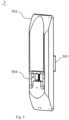
- Fig. 7is a schematic illustration of the horizontal movement joint according to an embodiment of the present invention.
- the horizontal movement joint 1may include a plurality of horizontal movement blocks that are stacked one above another and slidably connected to one another.
- Each of the horizontal movement blocksis configured to translate in the X-direction, and the topmost one of them is connected to the first rotational shaft 6.
- every adjacent two of the horizontal movement blocksare slidable interconnected to each other so that the upper horizontal movement block can slide on the lower horizontal movement block.
- these tandem sliding pairscan lengthen the stroke of the horizontal movement joint 1, making the robotic arm movable in a greater range with higher adjustment efficiency.
- the horizontal dimension of the horizontal movement joint 1can be reduced, reducing its installation space.
- each of the horizontal movement blocksmay include a base, a horizontal guide track (oriented horizontally) and a slider.
- the horizontal guide trackis fixed to the base, and the slider is slidable connected to the horizontal guide track so that it is horizontal slidable on the horizontal guide track.
- the base of the upper oneis fixed to the slider of the lower one.
- the slider of, or the base covers the slider of, the topmost horizontal movement blockis fixedly connected to the first rotational shaft 6.
- the first horizontal movement blockincludes a first base 101, a first horizontal guide track 102 fixed to the first base 101, and a first slider 103 slidably disposed on the first horizontal guide track 102.
- the second horizontal movement blockincludes a second base 104 fixed to the first slider 103, a second horizontal guide track 105 fixed to the second base 104, and a second slider 106 slidably disposed on the second horizontal guide track 105.
- the first rotational shaft 6is fixedly connected to the second slider 106.
- a third base 107may be fixedly provided on the second slider 106, and the first rotational shaft 6 is fixedly connected to the third base 107.
- the second base 104will translate on the first base 101.
- the second slider 106when the second slider 106 is manually driven, the third base 107 will translate on the second base 104.
- the first base 101may be fixed to any suitable surface and maintained stationary thereon.
- the second base 104is able to be driven to move only by the first slider 103, and the third base 107 is able to be driven to move either by the first slider 103 or by the second slider 106.
- the number of the horizontal movement blocksmay also be more than two, for example three or more, with limitation to the present invention. According to the present invention, using the guide tracks and sliders to enable the horizontal movement joint 1 provides for structural simplicity, high movement reliability and convenient manipulation.
- the robotic armmay further include a fourth brake 13 which is provided on the horizontal movement joint 1.
- the fourth brake 13is configured to control the movement of the horizontal movement joint 1.
- the fourth brake 13may be connected to the horizontal movement joint 1 by a second flexible member in a closed-loop manner, in order to control the position of the horizontal movement joint 1 during its movement.
- the fourth brake 13when the fourth brake 13 is out of service, the horizontal movement joint 1 can move in the X-direction under the action of an external force.
- the fourth brake 13may be activated to prevent the horizontal movement joint 1 moving.
- the fourth brake 13may be provided on the topmost horizontal movement block and the fourth brake 13 may be connected to both ends of the bottommost horizontal movement block by the second flexible member in a closed-loop manner.
- the fourth brake 13may be disposed on the third base 107, with the second connecting flexible member wound on the fourth brake 13 and having a left portion fixed to one end of the first base 101 and a right portion fixed to the other end of the first base 101, such that the length of the left portion and the right portion can be controlled by the fourth brake.
- the horizontal movement joint 1may also be provided with a fixed pulley block (including a plurality of fixed pulleys) which guides the left portion into fixed connection with the end of the first base 101 and guides the right portion into fixed connection with the other end of the first base 101.
- a fixed pulley blockincluding a plurality of fixed pulleys
- the fourth brake 13is provided to control the movement of the horizontal movement joint 1 with the present of the second flexible member.
- the horizontal movement joint 1may alternatively include only one horizontal movement block.
- the horizontal movement blockincludes a first base 101, a first horizontal guide track 102 fixed to the first base 101, a first slider 103 slidably disposed on the first horizontal guide track 102 and a second base 104 fixed to the first slider 103.
- the first rotational shaft 6is coupled to the second base 104, and the fourth brake 13 is provided on the second base 104 or on the first slider 103 in order to prevent the movement of the first slider 103.
- Fig. 8schematically illustrates the base of the vertical movement joint, which is in the form of a sleeve, in accordance with an embodiment of the present invention.
- the frame 501 of the vertical movement joint 5has a shape of sleeve, and the vertical guide track 502 of the vertical movement joint 5 is disposed within the frame 501, thereby the vertical guide track 502 works under a desirable environment for normal operation.
- only one horizontal movement joint 1is used in lieu of the conventional plurality of inter-nested rotary joints to enable horizontal movement of the robotic arm.
- This reduction in the number of the used jointssimplifies the structure of the robotic arm, minimizes its size and reduces its overall weight. Because of the simply structure, the motion control precision is also increased without irrelevant displacements, and the robotic arm is more conveniently manipulated.
- first and second rotary joints 2, 4are sleeved over and able to rotate about the respective parallel axis of the rotational shafts and are both fixedly connected to the connecting lever 3. In this way, it enable that the robotic arm is adjusted efficiently and preciously.
- the gravity-balancing mechanism for gravitationally balancing the vertical movement joint 5is provided within the connecting lever 3. As such, it can enable rational internal space utilization which results in effective reductions in the robotic arm's dimensions while fulfilling its function without affecting any other joint work. Moreover, it will not increase the weight of the vertical movement joint 5, with more precious vertical adjustment thereof.
- the frame 501 of the vertical movement joint 5has a surface that is complementary to the outer circumferential surface of the second rotary joint 4. This makes the vertical movement joint 5 possible to snuggly fit the second rotary joint 4, so that the robotic arm rotates smoothly and has a compact structure.
Landscapes
- Engineering & Computer Science (AREA)
- Health & Medical Sciences (AREA)
- Robotics (AREA)
- Surgery (AREA)
- Mechanical Engineering (AREA)
- Life Sciences & Earth Sciences (AREA)
- Nuclear Medicine, Radiotherapy & Molecular Imaging (AREA)
- Biomedical Technology (AREA)
- Heart & Thoracic Surgery (AREA)
- Medical Informatics (AREA)
- Molecular Biology (AREA)
- Animal Behavior & Ethology (AREA)
- General Health & Medical Sciences (AREA)
- Public Health (AREA)
- Veterinary Medicine (AREA)
- Pathology (AREA)
- Oral & Maxillofacial Surgery (AREA)
- Manipulator (AREA)
Description
- The present invention relates to the field of medical devices and, in particular, to a robotic arm for a medical surgical robot for use in minimally invasive surgery.
- Minimally invasive surgery, an interventional procedure that provides surgical treatment based on a minimal channel and a corresponding minimally invasive instrument, achieves comparable or better efficacy compared to traditional open surgery. Minimally invasive surgery is an area of intense interest in modern medical technology because of its various advantages over traditional open surgery, such as minimal operation wound, less bleeding and rapid physical recovery.
- As part of minimally invasive procedures, minimally invasive surgical robots have been growing rapidly. With patients' increasing requirements for surgical outcomes as well as physicians' increasing requirements for surgical methodologies, medical robotics are being more and more applied to the medical field, especially to minimally invasive surgery. Compared to classical minimally invasive procedures, those conducted by minimally invasive surgical robots mitigate physicians' stress during procedures and allow their more precise and flexible operations.
- Different from industrial robots, minimally invasive surgical robots are imposed with more stringent requirements in terms of motion accuracy, motion space and motion mode. Difficulty in manipulation of a minimally invasive surgical robot mainly lies in preoperative positioning and intraoperative control. Preoperative positioning involves positional adjustments between the surgical robot and the patient before the start of the procedure, while intraoperative control relates to real-time operation and control during the procedure. For any surgical robot, the positional adjustments of surgical instruments are necessary to be made by its robotic arm before the start of the procedure, and such adjustments will directly affect whether the procedure can be conducted successfully.
EP 0 629 475 A1 discloses an articulated arm for manipulators and industrial robots comprising an adjusting lever which can be pivoted by motor about a fixed axle and at the other end of which an intermediate lever is pivotably articulated via a shaft supported rotatably on the adjusting lever, the linearly movable lever arm being seated at the other end of the intermediate lever on a shaft, supported rotatably on the intermediate lever, and so as to be pivotable with said shaft, and tracking transmission means dependent on the pivoting movement of the adjusting lever acting at the shaft connected so as to be fixed in terms of rotation to the intermediate lever and at the shaft connected so as to be fixed in terms of rotation to the lever arm.CN 103 056 646 A discloses a robot for tightening screws that comprises a fixed seat, two rotary joints, two arms, an installing plate, an air cylinder, a connecting plate and a screw-fixing machine.CN 105 232 153 A discloses a mechanical arm for minimally invasive surgery.JP H08 318483 A JP S61 820 A JP H09 285989 A CN 104 942 826 A ,WO 2010/130817 A1 ,WO 2015/142786 A1 provide further prior art.- However, the robotic arms used in current minimally invasive surgical robots are associated with some drawbacks. Specifically, conventional robotic arms are often complicated structures which are bulky and inconvenient to manipulation. More specifically, there are two major issues in using such a conventional robotic arm:
- 1) A horizontal movement of the conventional robotic arm is usually achieved by the rotary joint, and it relies on a number of rotary joints nested within one another, instead of a horizontal movement joint, to achieve the horizontal movement. The rotary joints together with a vertical movement joint can achieve movement of the robotic arm in the three-dimensional space. This structure of joints, on the one hand, lead to expand the dimensions of the robotic arm and increase the weight of the robotic arm and hence the overall weight of the medical surgical robot, which contravenes the compactness and lightweight requirements of medical surgical robots. On the other hand, the inter-nested rotary joints of this structure increase the arm's structural complexity and hinder its precise motion control. Moreover, the rotary joints tend to experience displacements in irrelevant directions, necessitating too much unnecessary, tedious motion adjustment.
- 2) Different from most industrial robotic arms which use motor-driven joints for convenient control and operation, joints in medical robotic arms are rarely motor-driven ones, because such robotic arms are often required to be "self-locked" during surgical procedures, while current motors are inevitably associated with a certain degree of risk of failure. For this reason, most robotic arms of the medical surgical robot are manipulated manually for the sake of higher reliability. However, the greatest difficulty in such manual manipulation is how to overcome, during vertical movement of the robotic arm, the gravity of an article hung on the end of the robotic arm. The current solution for this problem is to dispose the vertical movement joint on the front of the robotic arm and balance the gravity with a heavy mass. This, however, significantly increases the weight of the surgical robot and makes it difficult to guarantee precise vertical adjustment.
- It is an objective of the present invention to provide a surgical robot and a robotic arm therefor, in order to solve one or more of the above problems with conventional robotic arms, such as high structural complexity, bulkiness and operational
- To this end, the provided robotic arm includes:
- a vertical movement joint, configured to move a heavy mass in a vertical direction;
- a rotary joint, sleeved over a rotational shaft and configured to rotate about the rotational shaft to drive the vertical movement joint to rotate; and
- a horizontal movement joint, configured to drive the rotational shaft to move in a horizontal direction.
- In the robotic arm, the horizontal movement joint is fixedly connected to one end of the rotational shaft and is perpendicular to the rotational shaft, wherein the robotic arm for a surgical robot further comprises a gravity-balancing mechanism for gravitationally balancing the heavy mass hung on the vertical movement joint.
- In the robotic arm, the rotary joint includes a first rotary joint and a second rotary joint, the rotational shaft including a first rotational shaft and a second rotational shaft parallel to the first rotational shaft, the first rotary joint sleeved over the first rotational shaft and able to rotate about the first rotational shaft, the second rotary joint sleeved over the second rotational shaft and able to rotate about the second rotational shaft, the connecting lever fixedly connected to both the first rotary joint and the second rotary joint, the horizontal movement joint fixedly connected to one end of the first rotational shaft, the vertical movement joint fixedly connected to one end of the second rotational shaft.
- In the robotic arm, the gravity-balancing mechanism is connected to the vertical movement joint and housed in the connecting lever.
- In the robotic arm, the gravity-balancing mechanism includes a constant-force spring, a spring connector, a guide assembly and a flexible member, the constant-force spring having one end fixedly connected to the connecting lever and the other end fixedly connected to the spring connector, the spring connector fixedly connected to the flexible member, the guide assembly provided at least on the connecting lever and on the vertical movement joint, the flexible member configured to be guided by the guide assembly into fixed connection with the vertical movement joint.
- Preferably, in the robotic arm, the gravity-balancing mechanism may further include a sliding slot oriented in the horizontal direction, the spring connector being received in the sliding slot to guide the movement of the spring connector in the horizontal direction.
- Preferably, in the robotic arm, the gravity-balancing mechanism may further include a proportional pulley, the flexible member including a first flexible member and a second flexible member, the first flexible member including a first end and a first body extending from the first end, the first end connected to the spring connector, the first body guided by the guide assembly into fixed connection with the proportional pulley, the second flexible member including a second end and a second body extending from the second end, the second end fixedly connected to the proportional pulley, the second body guided by the guide assembly into fixed connection with the vertical movement joint.
- Preferably, in the robotic arm, the guide assembly may include a plurality of fixed pulleys separately disposed on the connecting lever and on the vertical movement joint.
- Preferably, in the robotic arm, the vertical movement joint may include a frame, a vertical guide track fixed to the frame, and a connecting member slidably disposed on the vertical guide track, the frame in fixed connection with a connecting shaft of the second rotary joint, the connecting shaft in fixed connection with one end of the second rotational shaft.
- Preferably, in the robotic arm, the frame may have a surface that is complementary to an outer circumferential surface of the second rotary joint.
- Preferably, in the robotic arm, the frame may be fixedly connected to the connecting shaft by means of a mounting slot in a surface of the frame proximate the second rotary joint.
- Preferably, in the robotic arm, the frame may be in the form of sleeve, the vertical guide track being housed in the frame.
- Preferably, in the robotic arm, the robotic arm may further include at least one brake that is provided in the first rotary joint and/or the second rotary joint and configured to control the rotary of the first rotary joint and/or the second rotary joint on the respective rotational shaft(s).
- Preferably, in the robotic arm, the horizontal movement joint may include a plurality of horizontal movement blocks that are stacked one above another and slidably connected to one another, each of the plurality of horizontal movement blocks configured to move in the horizontal direction, and wherein the rotational shaft is fixedly connected to a topmost one of the plurality of horizontal movement blocks.
- Preferably, in the robotic arm, each of the horizontal movement blocks may include a base, a horizontal guide track fixed to the base, and a slider slidably disposed on the horizontal guide track, wherein for every adjacent two of the plurality of horizontal movement blocks, the base of an upper one is fixed to the slider of a lower one, and wherein the base or slider of the topmost one of the plurality of horizontal movement blocks is fixedly connected to the rotational shaft.
- Preferably, in the robotic arm, two horizontal movement blocks including a first horizontal movement block and a second horizontal movement block are provided, the first horizontal movement block including a first base, a first horizontal guide track fixed to the first base and a first slider slidably disposed on the first horizontal guide track, the second horizontal movement block including a second base fixedly connected to the first slider, a second horizontal guide track fixed to the second base and a second slider slidably disposed on the second horizontal guide track.
- Preferably, the robotic arm may further include a brake which is provided on the horizontal movement joint, wherein the brake is configured to limit movement of the horizontal movement joint.
- The present invention also provides a surgical robot including the robotic arm as defined in any one of the above paragraphs.
- In summary, the surgical robot and the robotic arm of the present invention offer the following benefits:
- 1. Only one horizontal movement joint is used in place of the conventional plurality of inter-nested rotary joints to enable horizontal movement of the robotic arm. Such a reduction in the number of the used joints simplifies the structure of the robotic arm, minimizes its dimensions and reduces its overall weight. In addition to the structural simplification, the motion control precision is also increased without irrelevant displacements, making simpler operation possible.
- 2. The first and second rotary joints are sleeved over and able to rotate about the respective parallel rotational shafts and are both fixedly connected to the connecting lever. In this way, adjustment efficiency and precision can be ensured.
- 3. The gravity-balancing mechanism for gravitationally balancing the vertical movement joint is received within the connecting lever, so that it enables rational internal space utilization to result in effective reductions in the robotic arm's dimensions, while fulfilling its function without affecting any other component. Moreover, it will not increase the weight of the vertical movement joint, ensuring good vertical adjustment precision thereof.
- 4. The frame of the vertical movement joint has a surface that is complementary to the outer circumferential surface of the second rotary joint. This makes the vertical movement joint possible to snuggly fit the second rotary joint, resulting in enhanced structural compactness.
Fig. 1 is an overall schematic illustration of a robotic arm of a surgical robot according to an embodiment of the present invention.Fig. 2 schematically shows movement directions of various joints in the robotic arm ofFig. 1 .Fig. 3 is a sectional view of a first rotary joint and a second rotary joint according to an embodiment of the present invention.Fig. 4 is a front view of a vertical movement joint according to an embodiment of the present invention.Fig. 5 is a rear view of a vertical movement joint according to an embodiment of the present invention.Fig. 6 is a schematic illustration of a gravity-balancing mechanism according to an embodiment of the present invention.Fig. 7 is a schematic illustration of a horizontal movement joint according to an embodiment of the present invention.Fig. 8 is a schematic illustration of a frame of a vertical movement joint, which is in the form of a sleeve, according to an embodiment of the present invention.- In these figures,
1-horizontal movement joint; 101-first base; 102-first horizontal guide track; 103-first slider; 104-second base; 105-second horizontal guide track; 106-second slider; 107-third base; 2-first rotary joint; 3-connecting lever; 4-second rotary joint; 5-vertical movement joint; 501-base; 502-vertical guide track; 503-connecting member; 504-mounting slot; 6-first rotational shaft; 7-second rotational shaft; 8-connecting shaft; 9-first brake; 10-second brake; 11-third brake; 1201-constant-force spring; 1202-spring connector; 1203-fixed pulley; 1204-sliding slot; 13-fourth brake. - The surgical robot and the robotic arm therefor proposed in the present invention will be described in further detail below with reference to
Figs. 1 to 8 , so that objects, advantages and features of the invention will appear more apparent. It is noted that the figures are provided in a very simplified form not necessarily presented to scale, with the only intention to facilitate convenience and clarity in explaining a few embodiments of the invention. Fig. 1 is an overall schematic illustration of the robotic arm of the surgical robot according to an embodiment of the present invention.Fig. 2 schematically shows movement directions of joints in the robotic arm ofFig. 1 .- As shown in
Figs. 1 to 2 , the robotic arm is suitable for use in a surgical robot, especially in a minimally invasive surgical robot. The robotic arm is movable in the three-dimensional space and includes a horizontal movement joint 1, a firstrotary joint 2, a connectinglever 3, a secondrotary joint 4 and avertical movement joint 5. The firstrotary joint 2 is sleeved over a firstrotational shaft 6 and is rotatable about the firstrotational shaft 6. The firstrotational shaft 6 may be fixed at the horizontal movement joint 1 in such a manner that it is perpendicular to thehorizontal movement joint 1. The secondrotary joint 4 is sleeved over a secondrotational shaft 7 and is rotatable about the secondrotational shaft 7. The horizontal movement joint 1 is configured to move horizontally and the vertical movement joint 5 to move vertically. Moreover, the axis of the firstrotational shaft 6 is parallel to the axis of the secondrotational shaft 7. - According to the present invention, only one horizontal movement joint 1 is used in place of the conventional plurality of inter-nested rotary joints to enable horizontal movement of the robotic arm. This reduction in the number of the used joints simplifies the structure of the robotic arm, minimizes its dimensions and reduces its overall weight, thus complying with the compactness and lightweight requirements of medical surgical robots. In addition to the structural simplification, the motion control precision is increased without displacements of rotary joints in irrelevant directions. Therefore, simpler operation is made possible.
- It is to be noted that the number of the rotary joints is not limited to two, and in some embodiments (not shown), there may be only one rotary joint. In this case, this one rotary joint is sleeved over one rotational shaft and is able to rotate about the rotational shaft. The connecting
lever 3 is fixedly connected both to the rotary joint and the vertical movement joint 5, and the horizontal movement joint 1 is fixedly connected to one end of the rotational shaft in such a manner that it is perpendicular to the rotational shaft. This also allows movement of the robotic arm in the three-dimensional space and can, of course, have the same beneficial effects as described above. - Compared to the embodiments with only one rotary joint, the embodiment of using the first
rotary joint 2 and the secondrotary joint 4 makes it possible to perform redundant adjustments of the robotic arm, i.e., coarse adjustments by the firstrotary joint 2 and fine adjustments by the second rotary joint 4 if necessary, thereby ensuring high adjustment precision and efficiency. - Preferably, the robotic arm further includes a gravity-balancing mechanism that is connected to the vertical movement joint 5 and configured to gravitationally balance the vertical movement joint 5, i.e., balancing a heavy mass hung on the
vertical movement joint 5. Moreover, the gravity-balancing mechanism is disposed within the connectinglever 3. In other embodiments, the vertical movement joint 5 may be equipped with a gravity-balancing mechanism itself. However, the vertical movement joint 5 equipping with the gravity-balancing mechanism will increase the gravitational load on the robotic arm end and affect the vertical adjustment precision. Therefore, it is preferred that the gravity-balancing mechanism is disposed within the connectinglever 3, because this can effectively reduce the dimensions of the robotic arm while enabling the mechanism to fulfill its function without affecting other components. - In the following description, the horizontal direction is referred as the "X-direction" (parallel to movement direction of the horizontal movement joint 1) and the vertical direction as the "Z-direction" (parallel to movement direction of the vertical movement joint 5). Of course, the horizontal direction may also be referred as the "Y-direction", depending on the direction in which the horizontal movement joint 1 is moving.
- More preferably, the horizontal movement joint 1 and the vertical movement joint 5 are manually driven to move. Herein, the term "manually" refers to the so-called "passive adjustments" in the art. A passive adjustment of a joint refers to movement of the joint caused by a force exerted by a human being rather than by a motor or other driving means. This is because the robotic arm is required to be "self-locked" during a surgical procedure, while maintaining it in the self-locked state with a motor or the like is not reliable due to its unavoidable risk of failure.
- As noted above, in case the robotic arm has two rotary joints, the robotic arm according to the embodiment has the four degrees of freedom. So it can translate in the X-direction, translate in the Z-direction, rotate about the first
rotational shaft 6 and rotate about the secondrotational shaft 7. - Preferably, the movement of the robotic arm of the present invention in these four degrees of freedom includes:
- 1) X-directional translation: translation of the robotic arm along the X-direction resulting from X-directional movement of the horizontal movement joint 1 caused by a manual driving;
- 2) Z-directional translation: translation of the robotic arm along the Z-direction resulting from Z-directional movement of the vertical movement joint 5 caused by a manual driving;
- 3) Rotation of the first rotary joint 2: the first
rotary joint 2 rotates about the firstrotational shaft 6 due to the fixed connection at one end of the firstrotational shaft 6 with the horizontal movement joint 1, optionally, the firstrotary joint 2 is in a rotatable connection with the firstrotational shaft 6 by a bearing, driven either manually or by a motor, without limitation to the present invention; - It will be appreciated that since the second
rotary joint 4 is integrally connected to the first rotary joint 2 by the connectinglever 3, the second rotary joint 4 will rotate in synchronization with the firstrotary joint 2. - 4) Rotation of the second rotary joint 4: similarly, the second
rotary joint 4 rotates about the secondrotational shaft 7. For example, a rotatable connection may be established with a bearing between the secondrotary joint 4 and the secondrotational shaft 7. As a result, the second rotary joint 4 may be driven either manually or by a motor to rotate about the secondrotational shaft 7. - In this embodiment, the vertical movement joint 5 may be fixedly connected to a connecting
shaft 8 proximate the secondrotary joint 4. The connectingshaft 8 may be fixedly connected to one end of the secondrotational shaft 7. As such, under the actuation of the secondrotational shaft 7, the vertical movement joint 5 will rotate with the connectingshaft 8 proximate the secondrotary joint 4. Fig. 3 is a sectional view of the first rotary joint and the second rotary joint according to an embodiment of the present invention. The vertical movement joint 5 may be connected at its back side (i.e., the side close to the second rotary joint 4) to the connectingshaft 8.Fig. 4 is a front view of the vertical movement joint according to an embodiment of the present invention, andFig. 5 is a rear view of the vertical movement joint ofFig. 4 . Here, the front side of the vertical movement joint refers to the side thereof away from the secondrotary joint 4, while the back side of the vertical movement joint refers to the side thereof proximate the secondrotary joint 4.- With reference to
Figs. 4 and5 , the vertical movement joint 5 may include aframe 501, a vertical guide track 502 (oriented vertically) and a connectingmember 503. The back side of theframe 501 is connected to the connectingshaft 8, and thevertical guide track 502 is oriented in the vertical direction and fixed to the front side of theframe 501. The connectingmember 503 is slidably connected to thevertical guide track 502 so that it can slide up and down on thevertical guide track 502. The connecting member is configured to connect an operating end portion of the robotic arm, on which a heavy mass can be hung. - In this embodiment, the
frame 501 may be fixedly connected to the connectingshaft 8 by means of a mountingslot 504 in its back side (i.e., the side proximate the second rotary joint 4). Optionally, an axis of the connectingshaft 8 may be perpendicular to the secondrotational shaft 7. Preferably, the back side of theframe 501 is complementary to an outer circumferential surface of the secondrotary joint 4. For example, the outer circumferential surface of the secondrotary joint 4 is a convexly-curved surface, whilst the back side of theframe 501 is a concavely-curved surface well matched with the outer circumferential surface of the secondrotary joint 4. This can increase the firmness of the connection between these joints. - With continued reference to
Fig. 3 , the robotic arm may further include afirst brake 9 and asecond brake 10. Thefirst brake 9 and thesecond brake 10 are separately housed within the first rotary joint 2 either on the same side or on the opposite sides of the firstrotational shaft 6. The brakes are configured to control the rotary of the firstrotary joint 2. That is, when the brakes are active, the first rotary joint 2 will be locked with respect to the firstrotational shaft 6, without any relative rotation between them. When the brakes are deactivated, the first rotary joint 2 can rotate on the firstrotational shaft 6 freely. The present invention is not limited to any particular number of brakes for control the rotary of the firstrotary joint 2. - Correspondingly, the robotic arm may further include a
third brake 11. Thethird brake 11 is disposed within the second rotary joint 4 on one side of the secondrotational shaft 7 and is configured to control the rotary of the secondrotary joint 4. Thethird brake 11 works in the same way as the first andsecond brakes Fig. 6 is a schematic illustration of the gravity-balancing mechanism according to an embodiment of the present invention. As shown inFig. 6 , the gravity-balancing mechanism is housed in the connectinglever 3 and may include a constant-force spring 1201, aspring connector 1202, a guide assembly and a first flexible member. One end of the constant-force spring 1201 is fixed to the connectinglever 3, and the other end of the constant-force spring 1201 is connected to thespring connector 1202. Thespring connector 1202 is connected to the first flexible member, and the guide assembly is provided at least on the connectinglever 3 and on the vertical movement joint 5 in order to guide an extension direction of the first flexible member so that the first flexible member is fixedly connected to the connectingmember 503 of thevertical movement joint 5. The first flexible member may be, for example, a wire, a rope, a belt or the like configured to output a spring force.- Optionally, the guide assembly may include a plurality of fixed
pulleys 1203. The plurality of fixedpulleys 1203 are separately disposed on the connectinglever 3 and the vertical movement joint 5 and configured to divert the first flexible member into fixed connection with the connectingmember 503. - According to the present invention, the constant-
force spring 1201 working as output a constant force of the gravity-balancing mechanism can achieve good gravitational balancing and avoid cumbersome calculations for dealing with gravitational changes, thus allowing a simpler gravitational balancing operation. - More preferably, the gravity-balancing mechanism may further include a sliding
slot 1204 disposed within the connectinglever 3 and oriented horizontally. Thespring connector 1202 may be received in the slidingslot 1204 so that thespring connector 1202 will move only in the horizontal direction with minor friction, resulting in a further improvement in gravitational balancing. - Further, the gravity-balancing mechanism may include a proportional pulley which has an inner rim and an outer rim, which a radius of the inner rim is proportional to a radius of the outer rim (not shown), and the first flexible member may include a first flexible portion and a second flexible portion. The first flexible portion has a first end and a first body extending from the first end. The first end is connected to the
spring connector 1202, and the first body is guided by a corresponding one of the fixedpulleys 1203 into fixed connection with the inner rim of the proportional pulley. The second flexible portion has a second end and a second body extending from the second end. The second end is fixedly connected to the outer rim of the proportional pulley, and the second body is guided by the another corresponding one of the fixedpulleys 1203 into fixed connection with the connectingmember 503. More preferably, the fixedpulley 1203 for guiding the extension direction of the first flexible portion is horizontally align to thespring connector 1202, in order to ensure a constant force output of the constant-force spring 1201. The proportional pulley may be disposed under the fixedpulley 1203 guiding the first flexible member, in order to achieve effective utilization of the internal space of the connectinglever 3. Fig. 7 is a schematic illustration of the horizontal movement joint according to an embodiment of the present invention. As shown inFig. 7 , the horizontal movement joint 1 may include a plurality of horizontal movement blocks that are stacked one above another and slidably connected to one another. Each of the horizontal movement blocks is configured to translate in the X-direction, and the topmost one of them is connected to the firstrotational shaft 6. In other words, every adjacent two of the horizontal movement blocks are slidable interconnected to each other so that the upper horizontal movement block can slide on the lower horizontal movement block. Compared to a single sliding pair, these tandem sliding pairs can lengthen the stroke of the horizontal movement joint 1, making the robotic arm movable in a greater range with higher adjustment efficiency. In addition, the horizontal dimension of the horizontal movement joint 1 can be reduced, reducing its installation space.- In this embodiment, each of the horizontal movement blocks may include a base, a horizontal guide track (oriented horizontally) and a slider. The horizontal guide track is fixed to the base, and the slider is slidable connected to the horizontal guide track so that it is horizontal slidable on the horizontal guide track. In addition, for every adjacent two of the horizontal movement blocks, the base of the upper one is fixed to the slider of the lower one. Further, the slider of, or the base covers the slider of, the topmost horizontal movement block is fixedly connected to the first
rotational shaft 6. - For example, two horizontal movement blocks may be provided, as shown in
Fig. 7 , i.e., a first horizontal movement block and a second horizontal movement block. The first horizontal movement block includes afirst base 101, a firsthorizontal guide track 102 fixed to thefirst base 101, and afirst slider 103 slidably disposed on the firsthorizontal guide track 102. The second horizontal movement block includes asecond base 104 fixed to thefirst slider 103, a secondhorizontal guide track 105 fixed to thesecond base 104, and asecond slider 106 slidably disposed on the secondhorizontal guide track 105. The firstrotational shaft 6 is fixedly connected to thesecond slider 106. Alternatively, athird base 107 may be fixedly provided on thesecond slider 106, and the firstrotational shaft 6 is fixedly connected to thethird base 107. - It will be appreciated that, when the
first slider 103 is manually driven, thesecond base 104 will translate on thefirst base 101. Similarly, when thesecond slider 106 is manually driven, thethird base 107 will translate on thesecond base 104. Here, those skilled in the art will recognize that thefirst base 101 may be fixed to any suitable surface and maintained stationary thereon. Thesecond base 104 is able to be driven to move only by thefirst slider 103, and thethird base 107 is able to be driven to move either by thefirst slider 103 or by thesecond slider 106. - In some other embodiments, the number of the horizontal movement blocks may also be more than two, for example three or more, with limitation to the present invention. According to the present invention, using the guide tracks and sliders to enable the horizontal movement joint 1 provides for structural simplicity, high movement reliability and convenient manipulation.
- In this embodiment, the robotic arm may further include a
fourth brake 13 which is provided on thehorizontal movement joint 1. Thefourth brake 13 is configured to control the movement of thehorizontal movement joint 1. For example, thefourth brake 13 may be connected to the horizontal movement joint 1 by a second flexible member in a closed-loop manner, in order to control the position of the horizontal movement joint 1 during its movement. Specifically, when thefourth brake 13 is out of service, the horizontal movement joint 1 can move in the X-direction under the action of an external force. Upon the horizontal movement joint 1 reaching a desired position, thefourth brake 13 may be activated to prevent the horizontal movement joint 1 moving. - In case of the horizontal movement joint 1 including a plurality of horizontal movement blocks, the
fourth brake 13 may be provided on the topmost horizontal movement block and thefourth brake 13 may be connected to both ends of the bottommost horizontal movement block by the second flexible member in a closed-loop manner. For example, thefourth brake 13 may be disposed on thethird base 107, with the second connecting flexible member wound on thefourth brake 13 and having a left portion fixed to one end of thefirst base 101 and a right portion fixed to the other end of thefirst base 101, such that the length of the left portion and the right portion can be controlled by the fourth brake. Of course, in order for better transmission control to be achieved, the horizontal movement joint 1 may also be provided with a fixed pulley block (including a plurality of fixed pulleys) which guides the left portion into fixed connection with the end of thefirst base 101 and guides the right portion into fixed connection with the other end of thefirst base 101. - Herein, the
fourth brake 13 is provided to control the movement of the horizontal movement joint 1 with the present of the second flexible member. - In some other embodiments (not shown), the horizontal movement joint 1 may alternatively include only one horizontal movement block. In this case, the horizontal movement block includes a
first base 101, a firsthorizontal guide track 102 fixed to thefirst base 101, afirst slider 103 slidably disposed on the firsthorizontal guide track 102 and asecond base 104 fixed to thefirst slider 103. Additionally, the firstrotational shaft 6 is coupled to thesecond base 104, and thefourth brake 13 is provided on thesecond base 104 or on thefirst slider 103 in order to prevent the movement of thefirst slider 103. Fig. 8 schematically illustrates the base of the vertical movement joint, which is in the form of a sleeve, in accordance with an embodiment of the present invention. As shown inFig. 8 , theframe 501 of the vertical movement joint 5 has a shape of sleeve, and thevertical guide track 502 of the vertical movement joint 5 is disposed within theframe 501, thereby thevertical guide track 502 works under a desirable environment for normal operation.- In summary, according to the present invention, only one horizontal movement joint 1 is used in lieu of the conventional plurality of inter-nested rotary joints to enable horizontal movement of the robotic arm. This reduction in the number of the used joints simplifies the structure of the robotic arm, minimizes its size and reduces its overall weight. Because of the simply structure, the motion control precision is also increased without irrelevant displacements, and the robotic arm is more conveniently manipulated.
- Additionally, the first and second
rotary joints lever 3. In this way, it enable that the robotic arm is adjusted efficiently and preciously. - Further, the gravity-balancing mechanism for gravitationally balancing the vertical movement joint 5 is provided within the connecting
lever 3. As such, it can enable rational internal space utilization which results in effective reductions in the robotic arm's dimensions while fulfilling its function without affecting any other joint work. Moreover, it will not increase the weight of the vertical movement joint 5, with more precious vertical adjustment thereof. - Furthermore, the
frame 501 of the vertical movement joint 5 has a surface that is complementary to the outer circumferential surface of the secondrotary joint 4. This makes the vertical movement joint 5 possible to snuggly fit the secondrotary joint 4, so that the robotic arm rotates smoothly and has a compact structure.
Claims (14)
- A robotic arm for a surgical robot, comprising:a vertical movement joint (5), configured to move a heavy mass in a vertical direction;a rotary joint, sleeved over a rotational shaft and configured to rotate about the rotational shaft to drive the vertical movement joint (5) to rotate; anda horizontal movement joint (1), configured to drive the rotational shaft to move in a horizontal direction,wherein the horizontal movement joint (1) is fixedly connected to one end of the rotational shaft and is perpendicular to the rotational shaft,wherein the robotic arm for a surgical robot further comprises a gravity-balancing mechanism for gravitationally balancing the heavy mass hung on the vertical movement joint (5), whereinthe rotary joint comprises a first rotary joint (2) and a second rotary joint (4), the rotational shaft comprising a first rotational shaft (6) and a second rotational shaft (7) parallel to the first rotational shaft (6);the first rotary joint (2) sleeved over the first rotational shaft (6) and able to rotate about the first rotational shaft (6), the second rotary joint (4) sleeved over the second rotational shaft (7) and able to rotate about the second rotational shaft (7);a connecting lever (3) fixedly connected to both the first rotary joint (2) and the second rotary joint (4);the horizontal movement joint (1) fixedly connected to one end of the first rotational shaft (6), the vertical movement joint (5) fixedly connected to one end of the second rotational shaft (7),the gravity-balancing mechanism is connected to the vertical movement joint (5) and housed in the connecting lever (3),the gravity-balancing mechanism comprises a constant-force spring (1201), a spring connector (1202), a guide assembly and a first flexible member, the constant-force spring (1201) having one end fixedly connected to the connecting lever (3) and the other end fixedly connected to the spring connector (1202), the spring connector (1202) fixedly connected to the first flexible member, the guide assembly provided at least on the connecting lever (3) and on the vertical movement joint (5), the first flexible member configured to be guided by the guide assembly into fixed connection with the vertical movement joint (5).
- The robotic arm for a surgical robot of claim 1, wherein the gravity-balancing mechanism further comprises a sliding slot (1204) oriented in the horizontal direction, the spring connector (1202) being received in the sliding slot (1204) to stop movement of the spring connector (1202) in the horizontal direction.
- The robotic arm for a surgical robot of claim 1 or 2, wherein the gravity-balancing mechanism further comprises a proportional pulley, the first flexible member comprising a first flexible portion and a second flexible portion, the first flexible portion comprising a first end and a first body extending from the first end, the first end connected to the spring connector (1202), the first body guided by the guide assembly into fixed connection with the proportional pulley, the second flexible portion comprising a second end and a second body extending from the second end, the second end fixedly connected to the proportional pulley, the second body guided by the guide assembly into fixed connection with the vertical movement joint (5).
- The robotic arm for a surgical robot of claim 3, wherein the guide assembly comprises a plurality of fixed pulleys (1203) separately disposed on the connecting lever (3) and on the vertical movement joint (5).
- The robotic arm for a surgical robot of claim 1, wherein the vertical movement joint (5) comprises a frame, a vertical guide track (502) fixed to the frame, and a connecting member (503) slidably disposed on the vertical guide track (502), the frame in fixed connection with a connecting shaft (8) proximate the second rotary joint (4), the connecting shaft (8) in fixed connection with one end of the second rotational shaft (7).
- The robotic arm for a surgical robot of claim 5, wherein the frame has a surface that is complementary to an outer circumferential surface of the second rotary joint (4).
- The robotic arm for a surgical robot of claim 5 or 6, wherein the frame is fixedly connected to the connecting shaft by means of a mounting slot in a surface of the frame proximate the second rotary joint.
- The robotic arm for a surgical robot of claim 5 or 6, wherein the frame is in the form of sleeve, the vertical guide track being housed in the frame.
- The robotic arm for a surgical robot of claim 1, further comprising at least one brake that is provided in the first rotary joint (2) and/or the second rotary joint (4) and configured to lock and immobilize the first rotary joint (2) and/or the second rotary joint (4) onto the respective rotational shaft(s).
- The robotic arm for a surgical robot of claim 1, wherein the horizontal movement joint (1) comprises a plurality of horizontal movement blocks that are stacked one above another and slidably connected to one another, each of the plurality of horizontal movement blocks configured to move in the horizontal direction, and wherein the rotational shaft is fixedly connected to a topmost one of the plurality of horizontal movement blocks.
- The robotic arm for a surgical robot of claim 10, wherein each of the plurality of horizontal movement blocks comprises a base (501), a horizontal guide track fixed to the base (501), and a slider slidably disposed on the horizontal guide track, wherein for every adjacent two of the plurality of horizontal movement blocks, the base (501) of an upper one is fixed to the slider of a lower one, and wherein the slider of, or the base (501) which covers the slider of, the topmost one of the plurality of horizontal movement blocks is fixedly connected to the rotational shaft.
- The robotic arm for a surgical robot of claim 11, wherein two horizontal movement blocks comprising a first horizontal movement block and a second horizontal movement block are provided, the first horizontal movement block comprising a first base (101), a first horizontal guide track (102) fixed to the first base (101) and a first slider (103) slidably disposed on the first horizontal guide track (102), the second horizontal movement block comprising a second base (104) fixedly connected to the first slider (103), a second horizontal guide track (105) fixed to the second base (104) and a second slider (106) slidably disposed on the second horizontal guide track (105).
- The robotic arm for a surgical robot of any one of claims 10 to 12, further comprising a brake which is provided on the horizontal movement joint (1), wherein the brake is configured to stop movement of the horizontal movement joint (1).
- A surgical robot, comprising the robotic arm of any one of claims 1 to 13.
Applications Claiming Priority (2)
| Application Number | Priority Date | Filing Date | Title |
|---|---|---|---|
| CN201610496647.7ACN106175934B (en) | 2016-06-29 | 2016-06-29 | Operating robot and its mechanical arm |
| PCT/CN2017/078604WO2018000870A1 (en) | 2016-06-29 | 2017-03-29 | Surgical robot and mechanical arm thereof |
Publications (3)
| Publication Number | Publication Date |
|---|---|
| EP3479775A1 EP3479775A1 (en) | 2019-05-08 |
| EP3479775A4 EP3479775A4 (en) | 2019-09-25 |
| EP3479775B1true EP3479775B1 (en) | 2023-03-22 |
Family
ID=57462658
Family Applications (1)
| Application Number | Title | Priority Date | Filing Date |
|---|---|---|---|
| EP17818869.4AActiveEP3479775B1 (en) | 2016-06-29 | 2017-03-29 | Surgical robot and mechanical arm thereof |
Country Status (4)
| Country | Link |
|---|---|
| EP (1) | EP3479775B1 (en) |
| CN (1) | CN106175934B (en) |
| BR (1) | BR112018077270B1 (en) |
| WO (1) | WO2018000870A1 (en) |
Families Citing this family (30)
| Publication number | Priority date | Publication date | Assignee | Title |
|---|---|---|---|---|
| CN106175934B (en)* | 2016-06-29 | 2019-04-30 | 微创(上海)医疗机器人有限公司 | Operating robot and its mechanical arm |
| CN106737850A (en)* | 2016-12-13 | 2017-05-31 | 山东威高手术机器人有限公司 | A kind of modular space adjusts mechanical arm |
| CN107374732B (en)* | 2017-07-31 | 2021-11-30 | 成都博恩思医学机器人有限公司 | A braking system and surgical robot for arm |
| CN110269685B (en)* | 2018-03-14 | 2021-02-19 | 深圳市精锋医疗科技有限公司 | Connecting assembly, operation arm, slave operation equipment and operation robot for minimally invasive surgery |
| WO2019191561A1 (en)* | 2018-03-29 | 2019-10-03 | Intuitive Surgical Operations, Inc. | Dual brake setup joint |
| CN109330689B (en)* | 2018-07-31 | 2024-01-09 | 深圳市精锋医疗科技股份有限公司 | Slave operation equipment assembly capable of adjusting operation arm and operation robot |
| CN108992182A (en)* | 2018-08-07 | 2018-12-14 | 华志微创医疗科技(北京)有限公司 | A kind of cranial surgery stereotactic apparatus and locking means with double locking function |
| CN109806011B (en)* | 2018-09-12 | 2024-01-12 | 苏州铸正机器人有限公司 | Auxiliary operation device |
| CN109394344B (en)* | 2018-12-29 | 2024-02-06 | 苏州康多机器人有限公司 | A kind of data self-calibration main operator |
| CN111481243B (en)* | 2019-01-29 | 2024-05-03 | 首都医科大学附属北京友谊医院 | Single-hole endoscope operation robot instrument straight line delivery device |
| DE102019205940A1 (en)* | 2019-04-25 | 2020-10-29 | Sumitomo (Shi) Demag Plastics Machinery Gmbh | Component handling device for component handling and injection molding machine equipped with it |
| CN110251197A (en)* | 2019-07-05 | 2019-09-20 | 四川大学 | An auxiliary device for spinal drilling surgery |
| CN110393587B (en)* | 2019-08-30 | 2024-08-30 | 山东威高手术机器人有限公司 | Mechanical arm rotating joint and doctor mechanical arm |
| CN110682276B (en)* | 2019-10-24 | 2024-08-02 | 河北工业大学 | Modularized light mechanical arm movement platform |
| CN110974445B (en)* | 2019-12-20 | 2024-08-09 | 深圳市资福医疗技术有限公司 | Magnetic control equipment with power assisting arm |
| CN111419402B (en)* | 2020-03-11 | 2024-10-01 | 浙江理工大学 | A deep brain stimulation assistive robot based on synchronous pulley |
| CN111329699B (en)* | 2020-04-03 | 2025-02-18 | 中科民生耐鼎机器人(珠海)有限公司 | A turntable-type flexible mechanical arm that can be rolled and retracted |
| CN111467035B (en)* | 2020-04-03 | 2023-01-13 | 哈尔滨工业大学 | Cross sliding table driving type hybrid spinal surgery robot |
| CN112228708A (en)* | 2020-09-30 | 2021-01-15 | 陶冬兰 | Quick positioning mechanical arm convenient to adjust |
| CN113232040B (en)* | 2021-05-19 | 2022-06-07 | 北京工业大学 | A high load-to-weight ratio manipulator with dual working modes |
| CN113695184A (en)* | 2021-08-13 | 2021-11-26 | 上海发那科机器人有限公司 | Retraction mechanism for robot pipeline |
| CN114533269B (en)* | 2021-09-13 | 2023-10-31 | 广西大学 | A surgical robot RCM positioning mechanism |
| CN114251571B (en)* | 2021-12-30 | 2023-07-07 | 杭州键嘉医疗科技股份有限公司 | A Pitch Angle Adjustment Structure of Navigation Binocular Camera with Adjustable Center of Gravity and Damping |
| CN114521959A (en)* | 2022-01-25 | 2022-05-24 | 苏州威森特医疗机器人有限公司 | Torque balance driving device for rotating shaft and actuating arm mechanism of surgical robot |
| CN114631893A (en)* | 2022-01-25 | 2022-06-17 | 苏州威森特医疗机器人有限公司 | Patient side execution part of surgical robot system |
| CN115153856A (en)* | 2022-07-29 | 2022-10-11 | 上海卓昕医疗科技有限公司 | Mechanical arm and movement control method thereof |
| US20240164946A1 (en)* | 2022-11-23 | 2024-05-23 | Vialase, Inc. | Mechanisms and methods with variable counterbalance to control movement and force of a head of a medical system at an anatomical site |
| US20240167524A1 (en)* | 2022-11-23 | 2024-05-23 | Vialase, Inc. | Mechanisms and methods with one-way braking to control movement of a head of a medical system relative to an anatomical site |
| US20240164862A1 (en)* | 2022-11-23 | 2024-05-23 | Vialase, Inc. | Mechanisms and methods to control movement of a head of a medical system relative to an anatomical site |
| CN118288335B (en)* | 2024-06-06 | 2024-09-03 | 山东康泰智能科技股份有限公司 | Flexible braking mechanism of intelligent robot joint and control method |
Citations (1)
| Publication number | Priority date | Publication date | Assignee | Title |
|---|---|---|---|---|
| WO2015142786A1 (en)* | 2014-03-17 | 2015-09-24 | Intuitive Surgical Operations, Inc. | Constant force spring with active bias |
Family Cites Families (21)
| Publication number | Priority date | Publication date | Assignee | Title |
|---|---|---|---|---|
| JPS61820A (en)* | 1984-06-14 | 1986-01-06 | Mitsubishi Electric Corp | Balance control device |
| CH687370A5 (en)* | 1993-06-15 | 1996-11-29 | Robotec Consulting Ag | Knickarmvorrichtung for handling machines and industrial robots. |
| US5825536A (en)* | 1994-09-12 | 1998-10-20 | Olympus Optical Co., Ltd. | Surgical microscope unit |
| JPH08318483A (en)* | 1995-05-22 | 1996-12-03 | Shibaura Eng Works Co Ltd | Industrial robot |
| JPH09285989A (en)* | 1996-04-19 | 1997-11-04 | Yamaha Motor Co Ltd | Multistage type extending/contracting device for industrial robot |
| JP2005254547A (en)* | 2004-03-10 | 2005-09-22 | Fanuc Ltd | Molding take-out device |
| KR100914387B1 (en)* | 2006-07-11 | 2009-08-28 | 가부시키가이샤 야스카와덴키 | Multijoint robot |
| CN101487558B (en)* | 2008-01-16 | 2012-01-25 | 鸿富锦精密工业(深圳)有限公司 | Lifting mechanism |
| GB0908368D0 (en)* | 2009-05-15 | 2009-06-24 | Univ Leuven Kath | Adjustable remote center of motion positioner |
| KR101180665B1 (en)* | 2009-07-03 | 2012-09-07 | 주식회사 이턴 | Hybrid surgical robot system and control method thereof |
| US20110187875A1 (en)* | 2010-02-04 | 2011-08-04 | Intouch Technologies, Inc. | Robot face used in a sterile environment |
| WO2012031635A1 (en)* | 2010-09-10 | 2012-03-15 | Abb Research Ltd. | Industrial robot |
| WO2013084221A1 (en)* | 2011-12-05 | 2013-06-13 | Mazor Robotics Ltd. | Active bed mount for surgical robot |
| CN103419189B (en)* | 2012-05-18 | 2016-05-18 | 范红兵 | A kind of robot drives structure |
| CN103876834B (en)* | 2012-12-19 | 2015-11-18 | 燕山大学 | Localization machine mechanical arm |
| CN103056646A (en)* | 2013-01-27 | 2013-04-24 | 郭祥英 | Screwing robot |
| CN104942826B (en)* | 2015-07-07 | 2016-06-29 | 亿嘉和科技股份有限公司 | A kind of robot lowering or hoisting gear and elevating method |
| CN105232153B (en)* | 2015-09-08 | 2019-03-26 | 微创(上海)医疗机器人有限公司 | Mechanical arm |
| CN105287003B (en)* | 2015-12-08 | 2017-08-25 | 微创(上海)医疗机器人有限公司 | Mechanical arm and its method of work |
| CN106175934B (en)* | 2016-06-29 | 2019-04-30 | 微创(上海)医疗机器人有限公司 | Operating robot and its mechanical arm |
| CN106037934B (en)* | 2016-06-29 | 2018-06-01 | 微创(上海)医疗机器人有限公司 | Surgical robot and its arm |
- 2016
- 2016-06-29CNCN201610496647.7Apatent/CN106175934B/enactiveActive
- 2017
- 2017-03-29EPEP17818869.4Apatent/EP3479775B1/enactiveActive
- 2017-03-29WOPCT/CN2017/078604patent/WO2018000870A1/ennot_activeCeased
- 2017-03-29BRBR112018077270-4Apatent/BR112018077270B1/ennot_activeIP Right Cessation
Patent Citations (1)
| Publication number | Priority date | Publication date | Assignee | Title |
|---|---|---|---|---|
| WO2015142786A1 (en)* | 2014-03-17 | 2015-09-24 | Intuitive Surgical Operations, Inc. | Constant force spring with active bias |
Also Published As
| Publication number | Publication date |
|---|---|
| WO2018000870A1 (en) | 2018-01-04 |
| CN106175934B (en) | 2019-04-30 |
| EP3479775A4 (en) | 2019-09-25 |
| CN106175934A (en) | 2016-12-07 |
| EP3479775A1 (en) | 2019-05-08 |
| BR112018077270A2 (en) | 2019-04-02 |
| BR112018077270B1 (en) | 2022-11-29 |
Similar Documents
| Publication | Publication Date | Title |
|---|---|---|
| EP3479775B1 (en) | Surgical robot and mechanical arm thereof | |
| CN102438540B (en) | Remote Motion Center Locator | |
| CN110292441B (en) | Constant force spring with active bias | |
| CN118217089B (en) | A surgical device and a surgical robot | |
| JP2781164B2 (en) | Auto-balance structure of medical stand device | |
| US20220395339A1 (en) | A hybrid, direct-control and robotic-assisted surgical system | |
| JP2018069048A (en) | Robot surgery table | |
| JP6563891B2 (en) | Robotic operating table and hybrid operating room | |
| US20160346940A1 (en) | Modular base link for a counterbalancing arm | |
| JP6216858B1 (en) | Robotic operating table | |
| EP4025152A1 (en) | Seven degree of freedom positioning device for robotic surgery | |
| KR102284387B1 (en) | Surgical system | |
| CN110916801A (en) | A surgical robot manipulator that can achieve high-precision positioning and attitude adjustment | |
| JPH06269463A (en) | Structure for adjusting biaxial balance of stand device for medical treatment | |
| CN114191085B (en) | Mechanical arm structure and surgical robot | |
| KR102283670B1 (en) | Master device for surgery to control slave device | |
| EP3476356B1 (en) | Medical arm assembly | |
| JP6586444B2 (en) | Robotic operating table and hybrid operating room system | |
| CN111745616B (en) | Force feedback master-slave operation controller | |
| JP6449957B2 (en) | Robotic operating table | |
| KR102285586B1 (en) | Gripper used in master device for surgery | |
| CN118453110B (en) | A system for positioning medical equipment | |
| CN117771069B (en) | A bed mechanical arm system | |
| CN115475012B (en) | Suspension type surgical robot system | |
| CN111685881B (en) | Freely-installed miniature bedside surgical robot and working method thereof |
Legal Events
| Date | Code | Title | Description |
|---|---|---|---|
| STAA | Information on the status of an ep patent application or granted ep patent | Free format text:STATUS: THE INTERNATIONAL PUBLICATION HAS BEEN MADE | |
| PUAI | Public reference made under article 153(3) epc to a published international application that has entered the european phase | Free format text:ORIGINAL CODE: 0009012 | |
| STAA | Information on the status of an ep patent application or granted ep patent | Free format text:STATUS: REQUEST FOR EXAMINATION WAS MADE | |
| 17P | Request for examination filed | Effective date:20190128 | |
| AK | Designated contracting states | Kind code of ref document:A1 Designated state(s):AL AT BE BG CH CY CZ DE DK EE ES FI FR GB GR HR HU IE IS IT LI LT LU LV MC MK MT NL NO PL PT RO RS SE SI SK SM TR | |
| AX | Request for extension of the european patent | Extension state:BA ME | |
| RIC1 | Information provided on ipc code assigned before grant | Ipc:B25J 9/04 20060101ALI20190607BHEP Ipc:B25J 18/02 20060101ALI20190607BHEP Ipc:A61B 34/30 20160101ALI20190607BHEP Ipc:F16M 11/08 20060101ALI20190607BHEP Ipc:B25J 18/04 20060101ALI20190607BHEP Ipc:B25J 19/00 20060101ALI20190607BHEP Ipc:B23Q 11/00 20060101ALI20190607BHEP Ipc:B25J 18/00 20060101ALI20190607BHEP Ipc:A61B 17/00 20060101AFI20190607BHEP Ipc:F16M 11/20 20060101ALI20190607BHEP Ipc:F16M 11/18 20060101ALI20190607BHEP Ipc:B25J 9/16 20060101ALI20190607BHEP Ipc:A61B 90/00 20160101ALI20190607BHEP Ipc:F16M 11/04 20060101ALI20190607BHEP | |
| A4 | Supplementary search report drawn up and despatched | Effective date:20190822 | |
| RIC1 | Information provided on ipc code assigned before grant | Ipc:B25J 18/00 20060101ALI20190816BHEP Ipc:F16M 11/18 20060101ALI20190816BHEP Ipc:B23Q 11/00 20060101ALI20190816BHEP Ipc:F16M 11/04 20060101ALI20190816BHEP Ipc:F16M 11/08 20060101ALI20190816BHEP Ipc:B25J 18/04 20060101ALI20190816BHEP Ipc:B25J 9/16 20060101ALI20190816BHEP Ipc:B25J 19/00 20060101ALI20190816BHEP Ipc:A61B 34/30 20160101ALI20190816BHEP Ipc:A61B 17/00 20060101AFI20190816BHEP Ipc:A61B 90/00 20160101ALI20190816BHEP Ipc:F16M 11/20 20060101ALI20190816BHEP Ipc:B25J 9/04 20060101ALI20190816BHEP Ipc:B25J 18/02 20060101ALI20190816BHEP | |
| DAV | Request for validation of the european patent (deleted) | ||
| DAX | Request for extension of the european patent (deleted) | ||
| RAP3 | Party data changed (applicant data changed or rights of an application transferred) | Owner name:SHANGAI MICROPORT MEDBOT (GROUP) CO., LTD. | |
| RAP3 | Party data changed (applicant data changed or rights of an application transferred) | Owner name:SHANGAI MICROPORT MEDBOT (GROUP) CO., LTD. | |
| STAA | Information on the status of an ep patent application or granted ep patent | Free format text:STATUS: EXAMINATION IS IN PROGRESS | |
| 17Q | First examination report despatched | Effective date:20220209 | |
| GRAP | Despatch of communication of intention to grant a patent | Free format text:ORIGINAL CODE: EPIDOSNIGR1 | |
| STAA | Information on the status of an ep patent application or granted ep patent | Free format text:STATUS: GRANT OF PATENT IS INTENDED | |
| INTG | Intention to grant announced | Effective date:20220711 | |
| GRAS | Grant fee paid | Free format text:ORIGINAL CODE: EPIDOSNIGR3 | |
| GRAJ | Information related to disapproval of communication of intention to grant by the applicant or resumption of examination proceedings by the epo deleted | Free format text:ORIGINAL CODE: EPIDOSDIGR1 | |
| GRAL | Information related to payment of fee for publishing/printing deleted | Free format text:ORIGINAL CODE: EPIDOSDIGR3 | |
| STAA | Information on the status of an ep patent application or granted ep patent | Free format text:STATUS: EXAMINATION IS IN PROGRESS | |
| INTC | Intention to grant announced (deleted) | ||
| GRAP | Despatch of communication of intention to grant a patent | Free format text:ORIGINAL CODE: EPIDOSNIGR1 | |
| STAA | Information on the status of an ep patent application or granted ep patent | Free format text:STATUS: GRANT OF PATENT IS INTENDED | |
| INTG | Intention to grant announced | Effective date:20230104 | |
| GRAA | (expected) grant | Free format text:ORIGINAL CODE: 0009210 | |
| STAA | Information on the status of an ep patent application or granted ep patent | Free format text:STATUS: THE PATENT HAS BEEN GRANTED | |
| AK | Designated contracting states | Kind code of ref document:B1 Designated state(s):AL AT BE BG CH CY CZ DE DK EE ES FI FR GB GR HR HU IE IS IT LI LT LU LV MC MK MT NL NO PL PT RO RS SE SI SK SM TR | |
| REG | Reference to a national code | Ref country code:GB Ref legal event code:FG4D | |
| REG | Reference to a national code | Ref country code:CH Ref legal event code:EP | |
| REG | Reference to a national code | Ref country code:DE Ref legal event code:R096 Ref document number:602017067051 Country of ref document:DE | |
| REG | Reference to a national code | Ref country code:IE Ref legal event code:FG4D | |
| REG | Reference to a national code | Ref country code:AT Ref legal event code:REF Ref document number:1554817 Country of ref document:AT Kind code of ref document:T Effective date:20230415 | |
| REG | Reference to a national code | Ref country code:LT Ref legal event code:MG9D | |
| REG | Reference to a national code | Ref country code:NL Ref legal event code:MP Effective date:20230322 | |
| PG25 | Lapsed in a contracting state [announced via postgrant information from national office to epo] | Ref country code:RS Free format text:LAPSE BECAUSE OF FAILURE TO SUBMIT A TRANSLATION OF THE DESCRIPTION OR TO PAY THE FEE WITHIN THE PRESCRIBED TIME-LIMIT Effective date:20230322 Ref country code:NO Free format text:LAPSE BECAUSE OF FAILURE TO SUBMIT A TRANSLATION OF THE DESCRIPTION OR TO PAY THE FEE WITHIN THE PRESCRIBED TIME-LIMIT Effective date:20230622 Ref country code:LV Free format text:LAPSE BECAUSE OF FAILURE TO SUBMIT A TRANSLATION OF THE DESCRIPTION OR TO PAY THE FEE WITHIN THE PRESCRIBED TIME-LIMIT Effective date:20230322 Ref country code:LT Free format text:LAPSE BECAUSE OF FAILURE TO SUBMIT A TRANSLATION OF THE DESCRIPTION OR TO PAY THE FEE WITHIN THE PRESCRIBED TIME-LIMIT Effective date:20230322 Ref country code:HR Free format text:LAPSE BECAUSE OF FAILURE TO SUBMIT A TRANSLATION OF THE DESCRIPTION OR TO PAY THE FEE WITHIN THE PRESCRIBED TIME-LIMIT Effective date:20230322 | |
| PGFP | Annual fee paid to national office [announced via postgrant information from national office to epo] | Ref country code:FR Payment date:20230516 Year of fee payment:7 Ref country code:DE Payment date:20230519 Year of fee payment:7 | |
| REG | Reference to a national code | Ref country code:AT Ref legal event code:MK05 Ref document number:1554817 Country of ref document:AT Kind code of ref document:T Effective date:20230322 | |
| PG25 | Lapsed in a contracting state [announced via postgrant information from national office to epo] | Ref country code:SE Free format text:LAPSE BECAUSE OF FAILURE TO SUBMIT A TRANSLATION OF THE DESCRIPTION OR TO PAY THE FEE WITHIN THE PRESCRIBED TIME-LIMIT Effective date:20230322 Ref country code:NL Free format text:LAPSE BECAUSE OF FAILURE TO SUBMIT A TRANSLATION OF THE DESCRIPTION OR TO PAY THE FEE WITHIN THE PRESCRIBED TIME-LIMIT Effective date:20230322 Ref country code:GR Free format text:LAPSE BECAUSE OF FAILURE TO SUBMIT A TRANSLATION OF THE DESCRIPTION OR TO PAY THE FEE WITHIN THE PRESCRIBED TIME-LIMIT Effective date:20230623 Ref country code:FI Free format text:LAPSE BECAUSE OF FAILURE TO SUBMIT A TRANSLATION OF THE DESCRIPTION OR TO PAY THE FEE WITHIN THE PRESCRIBED TIME-LIMIT Effective date:20230322 | |
| PG25 | Lapsed in a contracting state [announced via postgrant information from national office to epo] | Ref country code:SM Free format text:LAPSE BECAUSE OF FAILURE TO SUBMIT A TRANSLATION OF THE DESCRIPTION OR TO PAY THE FEE WITHIN THE PRESCRIBED TIME-LIMIT Effective date:20230322 Ref country code:RO Free format text:LAPSE BECAUSE OF FAILURE TO SUBMIT A TRANSLATION OF THE DESCRIPTION OR TO PAY THE FEE WITHIN THE PRESCRIBED TIME-LIMIT Effective date:20230322 Ref country code:PT Free format text:LAPSE BECAUSE OF FAILURE TO SUBMIT A TRANSLATION OF THE DESCRIPTION OR TO PAY THE FEE WITHIN THE PRESCRIBED TIME-LIMIT Effective date:20230724 Ref country code:ES Free format text:LAPSE BECAUSE OF FAILURE TO SUBMIT A TRANSLATION OF THE DESCRIPTION OR TO PAY THE FEE WITHIN THE PRESCRIBED TIME-LIMIT Effective date:20230322 Ref country code:EE Free format text:LAPSE BECAUSE OF FAILURE TO SUBMIT A TRANSLATION OF THE DESCRIPTION OR TO PAY THE FEE WITHIN THE PRESCRIBED TIME-LIMIT Effective date:20230322 Ref country code:AT Free format text:LAPSE BECAUSE OF FAILURE TO SUBMIT A TRANSLATION OF THE DESCRIPTION OR TO PAY THE FEE WITHIN THE PRESCRIBED TIME-LIMIT Effective date:20230322 | |
| REG | Reference to a national code | Ref country code:CH Ref legal event code:PL | |
| PG25 | Lapsed in a contracting state [announced via postgrant information from national office to epo] | Ref country code:SK Free format text:LAPSE BECAUSE OF FAILURE TO SUBMIT A TRANSLATION OF THE DESCRIPTION OR TO PAY THE FEE WITHIN THE PRESCRIBED TIME-LIMIT Effective date:20230322 Ref country code:PL Free format text:LAPSE BECAUSE OF FAILURE TO SUBMIT A TRANSLATION OF THE DESCRIPTION OR TO PAY THE FEE WITHIN THE PRESCRIBED TIME-LIMIT Effective date:20230322 Ref country code:IS Free format text:LAPSE BECAUSE OF FAILURE TO SUBMIT A TRANSLATION OF THE DESCRIPTION OR TO PAY THE FEE WITHIN THE PRESCRIBED TIME-LIMIT Effective date:20230722 | |
| REG | Reference to a national code | Ref country code:BE Ref legal event code:MM Effective date:20230331 | |
| PG25 | Lapsed in a contracting state [announced via postgrant information from national office to epo] | Ref country code:LU Free format text:LAPSE BECAUSE OF NON-PAYMENT OF DUE FEES Effective date:20230329 | |
| REG | Reference to a national code | Ref country code:DE Ref legal event code:R097 Ref document number:602017067051 Country of ref document:DE | |
| PG25 | Lapsed in a contracting state [announced via postgrant information from national office to epo] | Ref country code:MC Free format text:LAPSE BECAUSE OF FAILURE TO SUBMIT A TRANSLATION OF THE DESCRIPTION OR TO PAY THE FEE WITHIN THE PRESCRIBED TIME-LIMIT Effective date:20230322 | |
| REG | Reference to a national code | Ref country code:IE Ref legal event code:MM4A | |
| PLBE | No opposition filed within time limit | Free format text:ORIGINAL CODE: 0009261 | |
| STAA | Information on the status of an ep patent application or granted ep patent | Free format text:STATUS: NO OPPOSITION FILED WITHIN TIME LIMIT | |
| PG25 | Lapsed in a contracting state [announced via postgrant information from national office to epo] | Ref country code:SI Free format text:LAPSE BECAUSE OF FAILURE TO SUBMIT A TRANSLATION OF THE DESCRIPTION OR TO PAY THE FEE WITHIN THE PRESCRIBED TIME-LIMIT Effective date:20230322 Ref country code:MC Free format text:LAPSE BECAUSE OF FAILURE TO SUBMIT A TRANSLATION OF THE DESCRIPTION OR TO PAY THE FEE WITHIN THE PRESCRIBED TIME-LIMIT Effective date:20230322 Ref country code:LI Free format text:LAPSE BECAUSE OF NON-PAYMENT OF DUE FEES Effective date:20230331 Ref country code:IE Free format text:LAPSE BECAUSE OF NON-PAYMENT OF DUE FEES Effective date:20230329 Ref country code:DK Free format text:LAPSE BECAUSE OF FAILURE TO SUBMIT A TRANSLATION OF THE DESCRIPTION OR TO PAY THE FEE WITHIN THE PRESCRIBED TIME-LIMIT Effective date:20230322 Ref country code:CZ Free format text:LAPSE BECAUSE OF FAILURE TO SUBMIT A TRANSLATION OF THE DESCRIPTION OR TO PAY THE FEE WITHIN THE PRESCRIBED TIME-LIMIT Effective date:20230322 Ref country code:CH Free format text:LAPSE BECAUSE OF NON-PAYMENT OF DUE FEES Effective date:20230331 | |
| 26N | No opposition filed | Effective date:20240102 | |
| GBPC | Gb: european patent ceased through non-payment of renewal fee | Effective date:20230622 | |
| PG25 | Lapsed in a contracting state [announced via postgrant information from national office to epo] | Ref country code:BE Free format text:LAPSE BECAUSE OF NON-PAYMENT OF DUE FEES Effective date:20230331 | |
| PG25 | Lapsed in a contracting state [announced via postgrant information from national office to epo] | Ref country code:GB Free format text:LAPSE BECAUSE OF NON-PAYMENT OF DUE FEES Effective date:20230622 | |
| PG25 | Lapsed in a contracting state [announced via postgrant information from national office to epo] | Ref country code:IT Free format text:LAPSE BECAUSE OF FAILURE TO SUBMIT A TRANSLATION OF THE DESCRIPTION OR TO PAY THE FEE WITHIN THE PRESCRIBED TIME-LIMIT Effective date:20230322 | |
| REG | Reference to a national code | Ref country code:DE Ref legal event code:R119 Ref document number:602017067051 Country of ref document:DE | |
| PG25 | Lapsed in a contracting state [announced via postgrant information from national office to epo] | Ref country code:BG Free format text:LAPSE BECAUSE OF FAILURE TO SUBMIT A TRANSLATION OF THE DESCRIPTION OR TO PAY THE FEE WITHIN THE PRESCRIBED TIME-LIMIT Effective date:20230322 | |
| PG25 | Lapsed in a contracting state [announced via postgrant information from national office to epo] | Ref country code:BG Free format text:LAPSE BECAUSE OF FAILURE TO SUBMIT A TRANSLATION OF THE DESCRIPTION OR TO PAY THE FEE WITHIN THE PRESCRIBED TIME-LIMIT Effective date:20230322 | |
| PG25 | Lapsed in a contracting state [announced via postgrant information from national office to epo] | Ref country code:DE Free format text:LAPSE BECAUSE OF NON-PAYMENT OF DUE FEES Effective date:20241001 | |
| PG25 | Lapsed in a contracting state [announced via postgrant information from national office to epo] | Ref country code:FR Free format text:LAPSE BECAUSE OF NON-PAYMENT OF DUE FEES Effective date:20240331 | |
| PG25 | Lapsed in a contracting state [announced via postgrant information from national office to epo] | Ref country code:FR Free format text:LAPSE BECAUSE OF NON-PAYMENT OF DUE FEES Effective date:20240331 Ref country code:DE Free format text:LAPSE BECAUSE OF NON-PAYMENT OF DUE FEES Effective date:20241001 | |
| PG25 | Lapsed in a contracting state [announced via postgrant information from national office to epo] | Ref country code:CY Free format text:LAPSE BECAUSE OF FAILURE TO SUBMIT A TRANSLATION OF THE DESCRIPTION OR TO PAY THE FEE WITHIN THE PRESCRIBED TIME-LIMIT; INVALID AB INITIO Effective date:20170329 | |
| PG25 | Lapsed in a contracting state [announced via postgrant information from national office to epo] | Ref country code:HU Free format text:LAPSE BECAUSE OF FAILURE TO SUBMIT A TRANSLATION OF THE DESCRIPTION OR TO PAY THE FEE WITHIN THE PRESCRIBED TIME-LIMIT; INVALID AB INITIO Effective date:20170329 |