EP3477774B1 - Current guiding profile connector and current guiding arrangement - Google Patents
Current guiding profile connector and current guiding arrangementDownload PDFInfo
- Publication number
- EP3477774B1 EP3477774B1EP18199884.0AEP18199884AEP3477774B1EP 3477774 B1EP3477774 B1EP 3477774B1EP 18199884 AEP18199884 AEP 18199884AEP 3477774 B1EP3477774 B1EP 3477774B1
- Authority
- EP
- European Patent Office
- Prior art keywords
- current
- contact
- plug
- carrying profile
- carrying
- Prior art date
- Legal status (The legal status is an assumption and is not a legal conclusion. Google has not performed a legal analysis and makes no representation as to the accuracy of the status listed.)
- Active
Links
Images


Classifications
- H—ELECTRICITY
- H01—ELECTRIC ELEMENTS
- H01R—ELECTRICALLY-CONDUCTIVE CONNECTIONS; STRUCTURAL ASSOCIATIONS OF A PLURALITY OF MUTUALLY-INSULATED ELECTRICAL CONNECTING ELEMENTS; COUPLING DEVICES; CURRENT COLLECTORS
- H01R4/00—Electrically-conductive connections between two or more conductive members in direct contact, i.e. touching one another; Means for effecting or maintaining such contact; Electrically-conductive connections having two or more spaced connecting locations for conductors and using contact members penetrating insulation
- H01R4/10—Electrically-conductive connections between two or more conductive members in direct contact, i.e. touching one another; Means for effecting or maintaining such contact; Electrically-conductive connections having two or more spaced connecting locations for conductors and using contact members penetrating insulation effected solely by twisting, wrapping, bending, crimping, or other permanent deformation
- H01R4/18—Electrically-conductive connections between two or more conductive members in direct contact, i.e. touching one another; Means for effecting or maintaining such contact; Electrically-conductive connections having two or more spaced connecting locations for conductors and using contact members penetrating insulation effected solely by twisting, wrapping, bending, crimping, or other permanent deformation by crimping
- H01R4/183—Electrically-conductive connections between two or more conductive members in direct contact, i.e. touching one another; Means for effecting or maintaining such contact; Electrically-conductive connections having two or more spaced connecting locations for conductors and using contact members penetrating insulation effected solely by twisting, wrapping, bending, crimping, or other permanent deformation by crimping for cylindrical elongated bodies, e.g. cables having circular cross-section
- H01R4/184—Electrically-conductive connections between two or more conductive members in direct contact, i.e. touching one another; Means for effecting or maintaining such contact; Electrically-conductive connections having two or more spaced connecting locations for conductors and using contact members penetrating insulation effected solely by twisting, wrapping, bending, crimping, or other permanent deformation by crimping for cylindrical elongated bodies, e.g. cables having circular cross-section comprising a U-shaped wire-receiving portion
- H—ELECTRICITY
- H01—ELECTRIC ELEMENTS
- H01R—ELECTRICALLY-CONDUCTIVE CONNECTIONS; STRUCTURAL ASSOCIATIONS OF A PLURALITY OF MUTUALLY-INSULATED ELECTRICAL CONNECTING ELEMENTS; COUPLING DEVICES; CURRENT COLLECTORS
- H01R13/00—Details of coupling devices of the kinds covered by groups H01R12/70 or H01R24/00 - H01R33/00
- H01R13/02—Contact members
- H01R13/04—Pins or blades for co-operation with sockets
- H01R13/05—Resilient pins or blades
- H—ELECTRICITY
- H01—ELECTRIC ELEMENTS
- H01R—ELECTRICALLY-CONDUCTIVE CONNECTIONS; STRUCTURAL ASSOCIATIONS OF A PLURALITY OF MUTUALLY-INSULATED ELECTRICAL CONNECTING ELEMENTS; COUPLING DEVICES; CURRENT COLLECTORS
- H01R13/00—Details of coupling devices of the kinds covered by groups H01R12/70 or H01R24/00 - H01R33/00
- H01R13/02—Contact members
- H01R13/10—Sockets for co-operation with pins or blades
- H01R13/11—Resilient sockets
- H01R13/115—U-shaped sockets having inwardly bent legs, e.g. spade type
- H—ELECTRICITY
- H01—ELECTRIC ELEMENTS
- H01R—ELECTRICALLY-CONDUCTIVE CONNECTIONS; STRUCTURAL ASSOCIATIONS OF A PLURALITY OF MUTUALLY-INSULATED ELECTRICAL CONNECTING ELEMENTS; COUPLING DEVICES; CURRENT COLLECTORS
- H01R25/00—Coupling parts adapted for simultaneous co-operation with two or more identical counterparts, e.g. for distributing energy to two or more circuits
- H01R25/16—Rails or bus-bars provided with a plurality of discrete connecting locations for counterparts
- H01R25/161—Details
- H01R25/162—Electrical connections between or with rails or bus-bars
- H—ELECTRICITY
- H01—ELECTRIC ELEMENTS
- H01R—ELECTRICALLY-CONDUCTIVE CONNECTIONS; STRUCTURAL ASSOCIATIONS OF A PLURALITY OF MUTUALLY-INSULATED ELECTRICAL CONNECTING ELEMENTS; COUPLING DEVICES; CURRENT COLLECTORS
- H01R4/00—Electrically-conductive connections between two or more conductive members in direct contact, i.e. touching one another; Means for effecting or maintaining such contact; Electrically-conductive connections having two or more spaced connecting locations for conductors and using contact members penetrating insulation
- H01R4/28—Clamped connections, spring connections
- H01R4/48—Clamped connections, spring connections utilising a spring, clip, or other resilient member
- H01R4/4809—Clamped connections, spring connections utilising a spring, clip, or other resilient member using a leaf spring to bias the conductor toward the busbar
- H01R4/48185—Clamped connections, spring connections utilising a spring, clip, or other resilient member using a leaf spring to bias the conductor toward the busbar adapted for axial insertion of a wire end
- H01R4/4819—Clamped connections, spring connections utilising a spring, clip, or other resilient member using a leaf spring to bias the conductor toward the busbar adapted for axial insertion of a wire end the spring shape allowing insertion of the conductor end when the spring is unbiased
- H01R4/4823—Multiblade spring
- H—ELECTRICITY
- H01—ELECTRIC ELEMENTS
- H01R—ELECTRICALLY-CONDUCTIVE CONNECTIONS; STRUCTURAL ASSOCIATIONS OF A PLURALITY OF MUTUALLY-INSULATED ELECTRICAL CONNECTING ELEMENTS; COUPLING DEVICES; CURRENT COLLECTORS
- H01R4/00—Electrically-conductive connections between two or more conductive members in direct contact, i.e. touching one another; Means for effecting or maintaining such contact; Electrically-conductive connections having two or more spaced connecting locations for conductors and using contact members penetrating insulation
- H01R4/28—Clamped connections, spring connections
- H01R4/48—Clamped connections, spring connections utilising a spring, clip, or other resilient member
- H01R4/4809—Clamped connections, spring connections utilising a spring, clip, or other resilient member using a leaf spring to bias the conductor toward the busbar
- H01R4/4846—Busbar details
- H01R4/4848—Busbar integrally formed with the spring
- H—ELECTRICITY
- H01—ELECTRIC ELEMENTS
- H01R—ELECTRICALLY-CONDUCTIVE CONNECTIONS; STRUCTURAL ASSOCIATIONS OF A PLURALITY OF MUTUALLY-INSULATED ELECTRICAL CONNECTING ELEMENTS; COUPLING DEVICES; CURRENT COLLECTORS
- H01R9/00—Structural associations of a plurality of mutually-insulated electrical connecting elements, e.g. terminal strips or terminal blocks; Terminals or binding posts mounted upon a base or in a case; Bases therefor
- H01R9/22—Bases, e.g. strip, block, panel
- H01R9/24—Terminal blocks
- H01R9/2416—Means for guiding or retaining wires or cables connected to terminal blocks
- H—ELECTRICITY
- H01—ELECTRIC ELEMENTS
- H01R—ELECTRICALLY-CONDUCTIVE CONNECTIONS; STRUCTURAL ASSOCIATIONS OF A PLURALITY OF MUTUALLY-INSULATED ELECTRICAL CONNECTING ELEMENTS; COUPLING DEVICES; CURRENT COLLECTORS
- H01R9/00—Structural associations of a plurality of mutually-insulated electrical connecting elements, e.g. terminal strips or terminal blocks; Terminals or binding posts mounted upon a base or in a case; Bases therefor
- H01R9/22—Bases, e.g. strip, block, panel
- H01R9/24—Terminal blocks
- H01R9/2491—Terminal blocks structurally associated with plugs or sockets
Definitions
- the inventionrelates to a current-carrying profile connector with plug-in contacts and an insulating material housing, the receiving chambers for receiving a respective plug-in contact, conductor entry openings on a first end face of the insulating material housing, which open into each receiving chamber, and plug-in openings on a second end face of the insulating material housing, which is the first end face diametrically opposite and provides access to a respective receiving chamber.
- the plug-in contactsOn the side facing a conductor entry opening, the plug-in contacts have a spring connection contact with a clamping spring for connecting an electrical conductor and on the side facing a plug-in opening a fork contact formed from at least one pair of spring arms with two opposing spring arms or a blade contact formed from a contact tab protruding in the insertion direction.
- the inventionfurther relates to a current carrying arrangement with a plurality of current carrying profiles which have a carrier profile with a base surface, webs extending parallel to one another on the base surface and grooves and electrical conductors in such grooves bounded by a pair of webs, and with the above-mentioned current carrying profile Connectors.
- busbar systems with current-carrying profileswhich have a comb-like cross-section with webs and grooves formed by them and electrical conductors received in the grooves.
- these electrical conductorsare received in the grooves, for example on the side walls of the webs, and can be connected to a tap connector electrically conductive contact is made with contacts projecting into the grooves.
- the current-carrying profilesusually have a carrier profile made of plastic material that is installed in a metal trough. They have a relatively large extension length. With the usual thermal load, the electrical conductors made of metal, the metal trough and the support profile made of plastic expand differently.
- EP 1 284 033 B1shows a current carrying profile with a wire holding element with grooves in which electrical wires are received.
- the wire holding elementshave projections at their ends which, when two wire holding elements are brought together, overlap one another.
- the projectionsin this case form a composite channel for the wire in the transition area between two wire holding elements and allow, for example, temperature-related length compensation of the wire holding elements to one another.
- connection unit for a light bandis known.
- connection unit for a light bandis known.
- electrical connector with a spring-loaded terminal connection for an electrical conductoris known.
- the plug contactsbe accommodated in a respective receiving chamber so as to be displaceable in a plug-in direction extending from the first end to the second end of the insulating material housing.
- the plug contactshave a stop between the clamping spring of the spring connection contact and the fork or blade contact for the contact of an electrical conductor clamped to the spring connection contact, the clamping spring pointing towards the stop and inclined with respect to the plugging direction.
- the electrical connection of electrical conductors of current carrying profiles arranged one behind the other in an alignmentis made with such current carrying profile connectors.
- the electrical conductors of the current-carrying profilescan then each be inserted into a conductor entry opening and clamped to the spring connection contacts there.
- Two such current-carrying profile connectorscan be plugged together at their plug-in openings, a blade contact of a first current-carrying profile connector interacting with a fork contact of a second current-carrying profile connector.
- a current-carrying profile connectordoes not necessarily have to have the same type of plug-in contacts as either only blade contacts or only fork contacts. Different types of plug contacts can also be present in a mixed manner in a current-carrying profile connector, such as blade contacts and fork contacts.
- the plug contactsare arranged displaceably on a respective receiving chamber of the insulating material housing, they can move in their plugging direction with a different length expansion of the clamped-on electrical conductor and the carrier profile. Since two current-carrying profile connectors are plugged into one another with their plug-in opening and a sliding knife-fork contact is provided there, the knife contact can move relative to the fork contact during such a movement without the electrically conductive connection between the knife and fork contact being impaired becomes.
- the relative movement of a connector when the clamped electrical conductor extends in length to the stationary insulating material housing while ensuring a spring clamp contact resting against the clamped electrical conductoris achieved in that the electrical conductor abuts the stop of the plug contact with its end face and is fixed in position by the clamping spring Plug contact is clamped.
- the electrical conductor of the current-carrying profile clamped to a plug contactis prevented from moving relative to the plug contact on one side by the stop and on the other side by the clamping spring.
- a sliding movementis still possible due to the pairing of a fork contact with a blade contact of the plug-in current-carrying profile connector in order to ensure the length compensation in this way.
- the knife contact and / or the fork contactcan have a surface coating, at least on the contact surfaces, which ensures an even better sliding movement with constant contact resistance.
- a surface coatingcan be provided by a noble metal coating, e.g. can be realized by gold plating, by silver coating or the like.
- the plug contactscan be formed in one piece from a sheet metal part and have a bottom surface and side walls protruding from the opposite sides of the bottom surface. A ladder guide tunnel is provided by these side walls, which are spaced apart from one another and project from the floor surface in the same direction.
- the plug contacthas at least one clamping spring, each is released from a side wall.
- the side wallcan be cut or punched free from the base plate in the area of the clamping spring and the side wall can be separated transversely to the plane of the base surface.
- Such a clamping spring formed integrally with the side wall and connected to itcan then be bent out of the plane of the side wall in the direction of the opposite side wall. But it is also conceivable that a separate clamping spring is connected to a side wall, for example by soldering, welding, caulking or other joining.
- Such a plug contactis very simple and has a stable and compact structure due to the protruding side walls.
- a flap of materialcan protrude from the base plate to form a stop.
- This material flapcan be arranged in a space between the opposing side walls.
- the tunnel for inserting an electrical conductoris thus delimited laterally by the two side walls, from below by the base plate and in the insertion direction by the material flap.
- An electrical conductor of the current-carrying profile introduced into the conductor-routing tunnel between the side wallscan then be routed to the material flap in order to rest there.
- the electrical conductoris clamped to the plug contact by the clamping spring protruding from the side wall and not only contacted in an electrically conductive manner, but also held in a fixed position on the plug contact.
- the side wallscan be aligned obliquely to one another at the transition to the fork or knife contact.
- the connectoris tapered further in the plug-in direction of the spring connection contact.
- This area formed by the mutually inclined side wallsis preferably located in the area in which the stop is formed.
- the side wall sections which are aligned obliquely to one anothercan form the spring arms of a fork contact in a section separated from the base plate.
- the spring arms of the fork contactthus connect to the side walls of the plug contact and are held in a stable manner by the one-piece connection. In addition, a sufficiently large current cross-section is ensured in this way.
- the pair of spring armscan then have a contact area at the spring arm ends remote from the spring connection contact, to which insertion sections bent away from one another are connected.
- An insertion funnelis thus provided for inserting a knife contact into the fork contact and a contact area adjoining the inclined insertion sections with a small contact surface is realized. In this way, the contact pressure of the fork contacts is concentrated on this contact area with a reduced surface and in this way the surface pressure is increased and the contact resistance is reduced.
- the side wall sections aligned obliquely to one anothercan merge into contact lugs which run next to one another, extend parallel to one another and form a blade contact. In this way, too, a direct current transmission is achieved via the side wall sections into the blade contact with the largest possible current cross-section and a stable structure.
- the contact lugs running next to one anotherwhich preferably rest against one another, reduce the risk of the blade contacts bending.
- the increased knife thicknessis also advantageous with regard to the contact forces that can be achieved on the fork contacts, since they therefore do not require any pretensioning.
- a ground contactcan be slidably plugged into the plug contact and protrude from the plug contact.
- This embodimentis in principle independent of the specific design of current-carrying profile connectors.
- grounding contactBecause a separate grounding contact is slidably and thus slidably plugged into a plug-in contact, the grounding contact can remain connected in a fixed position to the grounding potential of the metal trough, for example, even if the carrier profile is located or move the electrical conductors built into it. Due to the sliding plug contact of the earthing contact on a plug contact that is used to connect two current-carrying profiles, movement of the connector does not affect the fixing of the earth contact, since these are slidably plugged into one another.
- the ground contactcan have a socket contact into which the contact tab of a connector described above is inserted.
- This contact lug of the connectorcan also be connected to a fork contact of a complementary connector in order to provide continuous wiring and at the same time an earth connection to protective earth (PE).
- PEprotective earth
- a current-carrying profile connectoris plugged into each of the end faces of two carrier profiles arranged one behind the other in an alignment.
- the electrical conductors of the support profile protruding from the end faceare each clamped to a spring connection contact of a plug-in contact of the current-carrying profile connector.
- the electrical conductorstrikes the stop of the plug contact and is clamped to the plug contact with the clamping spring.
- the current-carrying profile connectors plugged into the adjacent end faces of the two carrier profilesinterlock.
- a blade contact of a plug contact of a current-carrying profile connectoris slidably contacted with a fork contact of a plug-in contact of the other current-carrying profile connector.
- two carrier profiles arranged one behind the other in alignmentare connected by a pair of complementary current-carrying profile connectors which are each plugged into one end face of the two carrier profiles adjacent to one another.
- the electrical conductors protruding from the carrier profilesare inserted into the conductor entry openings of the current-carrying profile connector in order to be clamped with a spring connection contact.
- the plug contacts of the complementary current-carrying profile connectorcan move move relative to each other, the knife and fork contact arrangement ensuring a sliding contact, which can be linearly displaced in the plug-in direction, of the two complementary current-carrying profile connectors and thus of the carrier profiles that are aligned one behind the other.
- a first current-carrying profile connectorcan be plugged into an end face of a carrier rail. This first current guiding profile connector is then plugged together with a second complementary current guiding profile connector by engaging in one another in the area of their plug-in openings. A blade contact of a plug-in contact of one of these current-carrying profile connectors dips into a fork contact of a plug-in contact of the other current-carrying profile connector. In this way, a sliding contact, which is displaceable in the plugging direction, of the two plug contacts connected to one another is ensured.
- not only two carrier profiles arranged one behind the othercan be connected to one another in an electrically conductive manner.
- An electrical tap or an electrical supply line for energy or datacan also be provided on one end face.
- electrical connection linescan be inserted into conductor entry openings of the second current-carrying profile connector and each clamped to a spring connection contact of a plug contact of the second current-carrying profile connector.
- the conductor entry openings of the current-carrying profile connectorcan therefore not only be used to clamp the electrical conductors of the carrier profiles. They are equally suitable for connecting electrical connection cables that are independent of the carrier profiles. This can be rigid or flexible, multi-wire electrical connection lines.
- the insulating material housing of the current-carrying profile connectorcan have an outer contour that is matched to the front side contour of the front sides of the carrier rail and can be inserted flush into the front side contour. In this way, the current-carrying profile connector is fixed in position on the area of the end face of the carrier profile and a relative movement of the current-carrying profile connector relative to the carrier profile is prevented or at least greatly restricted.
- the front side contour of the carrier profile and the outer contour of the current-carrying profile connectorcan have locking elements for locking the current-carrying profile connector on the carrier profile. In this way, it is still possible to lock the current-carrying profile connector on the carrier profile after it has been plugged onto the end face of the carrier profile and to secure it from being pulled out. This locking can be so strong that the current-carrying profile connector rests precisely against the carrier profile and is held firmly on the carrier profile by means of a form fit.
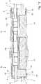
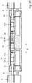
- Figure 1shows a perspective view of two complementary current-carrying profile connectors 1a, 1b, each of which has an insulating housing 2a, 2b.
- insulating material housing 2a, 2bOn a first end face 3 of the insulating material housing 2a, 2b, conductor entry openings 4 are made, which lead into receiving chambers for plug contacts.
- the insulating material housings 2a, 2bhave plug-in openings 6 on a second end face 5, which is diametrically opposite the first end face 3, which likewise provide access for a respective receiving chamber.
- the insulating material housings 2a, 2bare contoured on their second end face 5 and the plug area surrounding this second end face 5 so that the complementary current-carrying profile connectors 1a, 1b can be plugged into one another.
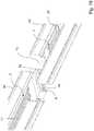
- Figure 2shows a perspective partial sectional view of a power supply arrangement with a power supply profile 7, which is formed from a support profile 8 and electrical conductors 9 built into the support profile.
- the carrier profile 8has a number of webs 10 which extend parallel to one another and each delimit a groove 11 for receiving an electrical conductor 9. It becomes clear that alternating grooves with different depths are provided, so that the electrical conductors 9 are arranged on two height levels.
- the electrical conductors 9protrude from the end faces of the carrier profile 8 in order to be contacted in an electrically conductive manner.
- the carrier profile 8On the front side, the carrier profile 8 has a platform 12 for supporting a current-carrying profile connector 1a, 1b.
- the current guiding profile connector 1 a, 1 bis plugged with its first end face 3 onto the end face of the current guiding profile 7.
- the plug-in direction Sis sketched with an arrow.
- the electrical conductors 9 of the current-carrying profile 7dip into respectively assigned conductor entry openings 4 of the current-carrying profile connector 1b in order to connect to a non-visible conductor connection contact in the interior.
- Figure 3shows the diametrically opposite end face of the carrier profile 7 from FIG. 2. There, too, the electrical conductors 9 protrude from the carrier profile 8 at two levels.
- a current-carrying profile connectorcan also be installed on this end face 1a with its end face 3 having the conductor entry openings 4 and resting on the platform 12.
- the contour of the current-carrying profile connectors 1a, 1b in the area of the conductor entry openings 4 or the first end face 3is adapted to the current-carrying profile 8 so that the current-carrying profile connectors 1a, 1b are pushed onto the platform 12 with their side walls in order to be positioned in the correct position in relation to the electrical conductors 9 and the associated conductor insertion openings 4 in this way.
- the platform 12has lateral, vertically protruding side walls, the side walls engaging in recesses on the respective current carrying profile connector 1a, 1b when the current-carrying profile connector 1a, 1b is plugged on.
- plug-in openings 6 on the second end face 5 of the current-carrying profile connectors 1a, 1benable access to plug-in contacts 13 which are accommodated in the interior of the current-carrying profile connectors 1a, 1b in respective receiving chambers. In this way, an electrically conductive contact can be made between a pair of plug contacts 13 of the first and second current-carrying profile connector 1a, 1b when they are plugged into one another.
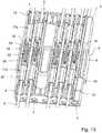
- Figure 4shows a plan view of a section of a power supply arrangement with the two power supply profile connectors 1a, 1b plugged into one another.
- the current-carrying profile connectors 1a, 1bhave a two-part insulating material housing 2a, 2b, each of which has a base body 14 and a cover part 15.
- the conductor entry openings 4are made in the cover part 15 and each lead to a receiving chamber 16 in the interior of the base body 14.
- a plug contact 17a, 17bwhich is longitudinally displaceable in the plugging direction S, is introduced into each of these receiving chambers 16. This is clearly one of the varying positions of the plug contacts 17a, 17b in relation to the adjoining cover part 15. It can be seen that the distances between the cover part 15, which delimits a receiving chamber 16, and the plug contact 17a, 17b arranged therein can vary.
- a first type of plug-in contacts 17aeach has a conductor connection contact 18 for clamping an electrical conductor 9 of a current-carrying profile 7 and at the other end area a blade contact 19 to form a plug-in contact connection for the second plug-in contact 17b of the complementary current-carrying profile connector 1b.
- This second type of plug-in contacts 17balso have a conductor connection contact 18 for clamping the electrical conductor 9 of a current-carrying profile 7 and at the other end a fork contact 20.
- Thisis also formed by two spring arms that are inclined to each other, which take up a blade contact 19 between them and by spring force clamp. It becomes clear that the blade contact 19 slides in the insertion direction S relative to the fork contact 20, so that the insertion depth of the blade contact 19 in the fork contact 20 can vary.
- the plug contacts 17a, 17beach have a stop 21 in the transition between the conductor connection contact 18 and the blade contact 19 or the fork contact 20, which is arranged in line with a conductor entry opening 4 in the insertion direction.
- the electrical conductor 9is inserted so far into the conductor connection contact 18 of the respective connector 17a, 17b that the front end of an electrical conductor 9 hits the stop 21.
- the electrical conductor 9is fixed in position by the conductor connection contact 18 on the respective plug connector 17a, 17b and can also no longer retreat.
- the electrical conductor 9With the help of the combination of the conductor connection contact 18 and the stop 21, the electrical conductor 9 is fixed in position on a respective plug contact 17a, 17b.
- the plug contact 17a, 17b clamped thereonmoves back and forth in the plugging direction relative to the insulating material housing 2a, 2b of the current-carrying profile connector.
- the plug contacts 17a, 17bare arranged displaceably in a respective receiving chamber 16 and by the sliding contact between the blade contact 19 and the fork contact 20 connected therewith a relative displacement of the two complementary first and second plug-in connectors 17a, 17b that are plugged together is possible.
- FIG. 4shows a sectional view of the power supply arrangement from FIG Figure 4 in the second mating level.
- the first plug connectors 17a and the second plug connectors 17bare alternately vertically offset transversely to the plug-in direction S, so that a plug connector 17a or 17b of a first plug level is arranged on a second plug level between two plug connectors 17a and 17b.
- the conductor connection contacts 18 of the plug connectors 17a, 17bare each formed by a spring connection contact with two opposing clamping springs 22.
- These clamping springs 22are each protruded from the plane of a side wall 23 into the interior of the plug contact 17a, 17b and point in the direction of the stop 21. They are integrally formed with the side walls 23 and claw into the clamped-on electrical conductor 9 so that the latter cannot be easily pulled away from the stop 21.
- the stop 21thus limits the degree of freedom of movement of a clamped-on electrical conductor 9 in the plug-in direction S, while the conductor connection contact 18 with the two clamping springs 22 restricts the degree of freedom of movement in the opposite direction.
- the different displacement positions of the first and second plug contacts 17a, 17bmake it clear that they are relatively displaceable to one another in the plugged-in state due to the knife and fork contacts 19, 20 and the resulting sliding contact.
- Different linear expansions of the electrical conductors 9 relative to the carrier profiles 8 and the insulating material housings 2a, 2b of the current-carrying profile connectorcan thus be compensated for in a simple and reliable manner.
- Figure 6shows a perspective view of a first plug contact 17a with a blade contact 19 at one end.
- the first plug contact 16ais formed in one piece from a sheet metal part. It has a bottom surface 24 from which the side walls 23 protrude from mutually opposite sides.
- a clamping spring 22is exposed from a side wall 23 on each of the opposing side walls 23.
- the clamping spring 22is cut or punched free from the sheet metal material of the side wall 23 towards the bottom surface 24 and transversely to the bottom surface 24.
- the clamping springs 22are bent out of the plane of that side wall 23 with which they are integrally connected.
- the two clamping springs 22are bent obliquely into the interior of the respective plug contact 17 a and aligned with the stop 21. There is a clamping distance between the free ends of the clamping spring 22 and the stop 21.
- the stop 21is bent out of the bottom surface 24, so that the stop 21 protrudes from the bottom surface 24 in the same direction as the side walls 23 and the clamping springs 22 formed thereon. With the help of the bottom surface 24 and the side walls 23, a conductor entry tunnel for a conductor to be clamped is created electrical conductor provided, which is then guided to the clamping point formed by the clamping ends of the clamping springs 22 and can abut the stop 21 with its end face.
- the stop 21is arranged in the area between the side wall sections 25, which are aligned obliquely to one another, and the clamping end of the clamping springs 22.
- material tongues 36are exposed from the side wall sections 25 and are bent inward toward the stop 21. With these optional material tongues 36, the stop 21 is stabilized and the risk of kinking due to a force acting on the stop 21 when an electrical conductor 9 is inserted is reduced.
- the blade contactcan optionally have a partial surface coating O in order to reduce the sliding friction and thus improve the sliding properties.
- This surface coatingcan e.g. can be realized by silver-plating or gold-plating the contact area.
- FIG. 7shows a perspective view of the second type of plug contact 17b.
- These plug contacts 17bare also formed in one piece from a sheet metal part and have a bottom surface 24 from which side walls 23 protrude on the opposite sides of the bottom surface 24.
- the conductor connection contact 18is again formed by clamping springs 22 which protrude obliquely from the side walls 23.
- the pair of clamping springs 22provide a funnel-shaped conductor clamping connection in which the electrical conductor is clamped by the clamping springs 22, which are spring-loaded towards one another.
- the side wall sections 25 which adjoin the clamping springs 22 and are aligned obliquely to one anotherform the spring arms 26 of a fork contact 20.
- These spring arms 26have, at their spring arm ends remote from the conductor connection contact 18, a contact area 27, to which insertion sections 28 bent away from one another are connected.
- These insertion sections 28point obliquely away from one another in order to provide an insertion funnel for inserting a blade contact 19 between the spring arms 26 of the fork contact 20.
- the optional material tongues 36are provided, which are exposed from the side wall sections 25 and bent inwards towards the stop 21 out of the plane of the respective side wall section 25.
- Figure 8shows a plan view of the power supply arrangement without the base body 14 of the insulating material housing 2a, 2b, but with the remaining cover part 15. It can be seen even more clearly that the nested pairs of first and second plug contacts 17a, 17b are relatively displaceable to one another in the plugging direction S, so that between the respective blade contact 19 and the assigned, Fork contacts 20 formed by the spring arms 26 a sliding contact is made.
- the blade contacts 19 and / or fork contacts 20can be surface-coated in order to improve the current transfer between the blade contact 19 and the fork contact 20 attached to it.
- the depth of insertion of the blade contacts 19 into an associated fork contact 20can thus change to compensate for changes in length of the electrical conductors 9 connected to one another or to compensate for length tolerances.
- Figure 9shows a sectional view of the power supply arrangement with only one pair of first and second plug-in contacts 17a, 17b inserted into the receiving chambers 16 of the base body 14 of a first and second insulating material housing 2a, 2b. It can be seen that the receiving chambers 16 are accessible from the first end face 3 of the two current-carrying profile connectors 1 a, 1 b via the conductor entry openings 4 made in the cover part 15.
- the grooves 11 of the support profiles 8 of a current-carrying profile 7are aligned with a conductor entry opening 4 of the front-side adjoining current-carrying profile connector 1a, 1b, and this conductor entry opening 4 is aligned with a receiving chamber 16.
- the base body 14 of the first insulating material housing 2a of the current-carrying profile connector 1a designed with a blade contacthas a receiving slot 29 for receiving a blade contact 19.
- This receiving slot 29is diametrically opposite the conductor insertion opening 4 for the same receiving chamber 16.
- This receiving slot 29is adapted to the blade contact 19 in such a way that it can be displaced into the receiving slot 29, but cannot be inclined in a direction other than the insertion direction.
- the receiving slot 29forms part of the plug-in opening 6, which provides access to the knife and fork contacts 18, 19 for plugging in a complementary current-carrying profile connector 1a, 1b and opens into the associated receiving chambers 16.
- the receiving chamber 16 in the base body 14 of the second insulating material housing 2balso has two guide slots 31 spaced from one another by a web 30, which are each adapted to receive a spring arm 26 of a fork contact 20.
- FIG. 10shows the sectional view of the power supply arrangement from FIG Figure 9 with the difference that the position of the plug contacts 17a, 17b in the respective receiving space 16 is changed by the length expansion of the electrical conductors 9. It becomes clear that the fork contact 20 with its insertion sections 28 abuts the boundary walls of the guide slots 29 of the complementary current-carrying profile connector 1a. This is an end position for the second plug contact 17b, which as in FIG Figure 9 shown in the other end position rests against the cover part 15 without a gap.
- the first plug contact 17ais shown in FIG Figure 10 in a position in which it rests against the cover part 15 with its end leading to the conductor connection contact 18 without a gap.
- this first plug contact 17ais in a different end position in which the blade contact 19 dips maximally into the guide slot 29 and protrudes from it.
- Figure 11shows a side sectional view through a complementary pair of nested current-carrying profile connectors 1a, 1b. It becomes clear that the cover parts 15 are each inserted into the base body 14 and latched into the base body 14 by means of locking lugs 32. The locking lugs 32 dip into locking openings 33 of the base body 14.
- the conductor entry openings 4 in the cover part 15are arranged on two levels and are alternately offset from this.
- first and second plug contacts 17a, 17b plugged into one anotherare arranged in alignment with the diametrically opposite conductor entry openings 4 of the two current-carrying profile connectors 1a, 1b.
- the electrical conductors 9 of two current-carrying profiles 7 arranged in an alignment adjacent to one anothercan be connected to one another.
- FIG. 11shows the side sectional view of the current guiding profile connector 1a, 1b from FIG Figure 11
- the current-carrying profile connectors 1a, 1bare each supported on a platform 12 of a current-carrying profile 7, with the electrical conductors 9 protruding from a current-carrying profile 7 through a conductor receiving opening 4 in the first end face 3 into a associated receiving chamber 16 are introduced.
- the free end of the electrical conductors 9abut the stop 21 of the plug contact 17a, 17b arranged in the receiving chamber 16.
- the clamping spring 22 of the conductor connection contact 18rests laterally on the electrical conductors 9 and digs into the electrical conductor 9.
- first and second plug contacts 17a, 17bare aligned in such a way that the blade contact 19 is acted upon laterally by a spring arm 26 of the fork contact 20 of the second plug connector 17b.
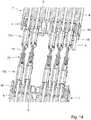
- Figure 13shows a perspective view of two nested current-carrying profile connectors 1a, 1b. It becomes clear that the electrical conductors, after exiting a conductor entry opening 4 in the cover part 15, reach a receiving chamber 16 and are guided there from a conductor routing tunnel of the conductor connection contact 18 to a clamping point formed by the clamping springs 22. It is also clear that the blade contact 19 is encompassed on both sides by the spring arms 26 of the fork contact 18.
- Figure 14shows a perspective view of the nested pair of current-carrying profile connectors 1a, 1b without the base body 14. It is clear that the plug contacts 17a, 17b are partially in direct contact with the adjacent cover part 15 or are spaced apart from it by a gap. This depends on the respective length expansion of the electrical conductor 9 clamped thereon.
- the conductor entry openings 4 in the cover parts 15are each arranged in a row on two height levels. Between two conductor entry openings 4 of a row, a further conductor entry opening 4 is arranged alternately offset in a plane which is offset in height relative to this and which form a second row.
- Figure 15shows a side sectional view through the power supply arrangement. It becomes clear that the conductor entry openings 4 are located on several, here for example two height levels and the plug contacts 17a, 17b are also arranged alternately offset on these two height levels.
- FIG. 11shows a perspective partial sectional view of a power supply arrangement in which a power supply profile 7 is built into a metal trough 34. It becomes clear that a first current guiding profile connector 1 a is plugged onto the end face of the current guiding profile 7. In the same or in an adjoining metal trough 34, a complementary second current-carrying profile connector 1b is provided, which is plugged together on the second end face 6 of the first current-carrying profile connector 1a. In the exemplary embodiment shown, this second current-carrying profile connector 1b now serves as a feeder and is connected to connection lines 35 which are inserted into the conductor entry openings 4 on the first end face 3 in the second current-carrying profile connector 1b and connected to the plug contacts 17b there. Such connecting lines 35 can be voltage supply lines for voltage potential L, the neutral conductor N. and ground potential PE or data lines, for example for a communication bus.
- Such connecting lines 35can be voltage supply lines for voltage potential L, the neutral conductor N. and ground potential PE or data
- the current-carrying profile 7has two connection areas separated from one another by a wider groove, either for two voltage circuits or on the one hand for a voltage supply and on the other hand for a communication bus.
- Figure 17shows a perspective view of a pair of plug contacts 17a, 17b, which are used together in a common insulating housing 2a, 2b of a current-carrying profile connector 1a, 1b.
- first type of plug contact 17a with blade contact 19is provided at one end.
- a fork contact of a second plug contact 17b of the second typeis plugged onto this blade contact 19.
- the two plug contacts 17a, 17bcan be displaced relative to one another when the electrical conductors clamped to them each expand differently.
- a further fork contact 20 of a plug contact 17b of another current-carrying profile connector 1a, 1bcan then still be plugged onto the blade contact 19, as has already been shown in detail above.
- the current pathcan be divided between two electrical conductors 9 of a common current-carrying profile 8 to be clamped. This allows the power line cross-section to be increased.
- Figure 18shows the pair of first and second connectors 17a, 17b Figure 17 in the perspective view with a view of the conductor connection contacts 18. These are again designed as a spring clamp contact for clamping an electrical conductor and have at least one pair of spring arms formed from two opposing spring arms 22 for this purpose.
- the fork contacts 20have a transverse web lying between the spring arms 26 and the contact area 27.
- the contact area 27is thus out of the mating plane of the second plug contact 17b for the electrical conductor, i.e. the plane of the clamping springs 22 into the mating plane of the first plug contact 17a, i.e. the mating plane of the blade contact 19 is offset.
- Figure 19shows another embodiment of such a pair of plug contacts 17a, 17b for a common insulating material housing 2a, 2b of a current-carrying profile connector 1a, 1b.
- the fork contact 20angled from the spring arms 26 to the plane of the blade contact 19 above.
- the spring arms 26 extending in the direction of extent of the clamping springs 22 of the plug contact 17bare thus adjoined by a spring arm section of the fork contacts 20 which is angled transversely thereto and which carries the contact area 27 at its free end area. This is then not again as in the first exemplary embodiment in FIG Figures 17 and 18 Angled in mating direction S.
- Figure 20shows a perspective view of the pair of plug contacts 17a, 17b from Figure 19 with a view of the conductor connection contacts 18. These are as in the previous in connection with Figures 6 and 7 described embodiments configured. With the aid of the fork contact 20 of the plug contact 17b angled in the direction of the plane of the blade contact 19, the two plug contacts 17a, 17b can be contacted with one another in a sliding, electrically conductive manner.
- FIG 21shows a perspective view of a first plug contact 17a with blade contacts 19 at one end.
- This plug contact 17chas a one-piece ground contact formed with it (PE contact / Protective Earth).
- This grounding contact 37is molded onto a side wall 23.
- the grounding contact 37is formed from a piece of sheet metal in the plane of this side wall 23 and has two clamping tongues 39 which are separated from one another by a slot 38 and which merge into a common root region 40.
- the front edges of the clamping tongues 39have teeth 41 facing one another, with which the grounding contact 37 is attached to a piece of sheet metal, e.g. a metal trough can be clawed.
- a combination of a protruding tooth 42 with an opposing recess 43can be provided in order to deform the sheet metal piece into the recess 43 and in this way fix the grounding contact 37 on the sheet metal piece with regard to its position.
- FIG. 22shows a perspective view of the plug contact 17c with a view of the conductor connection contact 18.
- the grounding contact 37adjoins the left side wall 23 there and is aligned with the plane of the side wall 23.
- the two clamping tongues 39 located in this planecan claw into a sheet metal section of the metal trough with a relatively large spring force through the common root area and through the subsequent piece of sheet metal merging into the side wall 23 in order to ensure a grounding connection in this way.
- Figure 24shows a plan view of a section through a power supply arrangement with two power supply profile connectors 1a, 1b plugged into one another.
- the plug contacts 17a of the first type described above and 17b of the second typeare introduced.
- the electrical conductors 9 inserted in the current-carrying profiles 8are each clamped to the conductor connection contacts 18 of the plug contacts 17a, 17b.
- the electrical conductors 9are led to the respective stops 21 and are not only electrically contacted by a pair of spring contacts with two opposing spring arms 20, but are also clawed at the respective plug contact 17a, 17b.
- the plug contact 17a, 17b clamped thereonmoves with it relative to the insulating material housing 2a, 2b.
- the plug contacts 17a of the first type of the current-carrying profile connector 1aare not displaced.
- the plug-in contacts 17b of the complementary current-carrying profile connector 1bare spaced apart from the cover part 15 by a gap and thus somewhat e.g.
- the electrical conductor 9is displaced by a linear expansion.
- FIG. 11shows a side sectional view of the power supply arrangement from FIG Figure 24 .
- the complementary current-carrying profile connectors 1a, 1bare plugged into one another with their insulating-material housings 2a, 2b.
- the fork contacts 20 of the plug contact 17b of the second typeencompass the blade contact 19 of the plug contact 17a of the first type.
- the fork contacts 20can, for example, also be formed by two or more spring arms that are independently resilient and separated by a gap.
- the two plug contacts 17a, 17bcan be displaced relative to one another in the plugging direction S in the respective insulating material housing 2a, 2b.
- Figure 26shows a side partial sectional view through a metal trough 34.
- current-carrying profiles 8are installed in this metal trough 34.
- the electrical conductors 9 of the current-carrying profiles 8are connected to one another with the aid of the current-carrying profile connectors 1a, 1b plugged into one another.
- the current guiding profile connectors 1a, 1beach have a canopy 44 on the end face facing the adjacent current guiding profile 8. This partially covers the adjacent current-carrying profile 8 and provides contact protection for the electrical conductors 9 underneath.
- This canopy 44which can also be referred to as a collar, opens the gap between the current-carrying profile 8 and the insulating material housing 2a, 2b of the respective current-carrying profile connector 1a, 1b covered and a finger security between the insulating material housing 2a, 2b of the current-carrying profile connector 1a, 1b and the current-carrying profile 8 is ensured. This is particularly advantageous when the gap is quite large.
- FIG. 13shows a perspective view of the power supply arrangement from FIG Figure 26 .
- the canopy 44 of the current-guiding profile connector 1a, 1beach covers the top of the adjacent current-guiding profile 8 and rests laterally with side wall sections on the current-guiding profile 8.
- the canopy 44thus surrounds the respective current-carrying profile 8.
- the canopy 44can be formed in one piece with the insulating housing 2a, 2b from the insulating material. However, it can also be attached to the insulating housing 2a, 2b as a separate part.
- FIG. 11shows a partial sectional view of the power supply arrangement from FIG Figure 27 .
Landscapes
- Connector Housings Or Holding Contact Members (AREA)
- Coupling Device And Connection With Printed Circuit (AREA)
Description
Translated fromGermanDie Erfindung betrifft einen Stromführungsprofil-Verbinder mit Steckkontakten und einem Isolierstoffgehäuse, das Aufnahmekammern zur Aufnahme jeweils eines Stecckontaktes, Leitereinführungsöffnungen an einer ersten Stirnseite des Isolierstoffgehäuses, die in die jeweils eine Aufnahmekammer ausmünden, und Stecköffnungen an einer zweiten Stirnseite des Isolierstoffgehäuses, die der ersten Stirnseite diametral gegenüberliegt und einen Zugang in jeweils eine Aufnahmekammer bereitstellt, aufweist. Die Steckkontakte weisen an der einer Leitereinführungsöffnung zugewandten Seite einen Federanschlusskontakt mit einer Klemmfeder zum Anklemmen eines elektrischen Leiters und an der einer Stecköffnung zugewandten Seite einen aus zumindest einem Federarmpaar mit zwei einander gegenüberliegenden Federarmen gebildeten Gabelkontakt oder einen aus einer in Steckrichtung abragenden Kontaktfahne gebildeten Messerkontakt auf.The invention relates to a current-carrying profile connector with plug-in contacts and an insulating material housing, the receiving chambers for receiving a respective plug-in contact, conductor entry openings on a first end face of the insulating material housing, which open into each receiving chamber, and plug-in openings on a second end face of the insulating material housing, which is the first end face diametrically opposite and provides access to a respective receiving chamber. On the side facing a conductor entry opening, the plug-in contacts have a spring connection contact with a clamping spring for connecting an electrical conductor and on the side facing a plug-in opening a fork contact formed from at least one pair of spring arms with two opposing spring arms or a blade contact formed from a contact tab protruding in the insertion direction.
Die Erfindung betrifft weiterhin eine Stromführungsanordnung mit einer Mehrzahl von Stromführungsprofilen, die ein Trägerprofil mit einer Basisfläche, parallel zueinander erstreckende Stegen auf der Basisfläche und jeweils durch ein Paar von Stegen begrenzte Nuten und elektrische Leitern in solchen Nuten aufweisen, und mit den oben genannten Stromführungsprofil-Verbindern.The invention further relates to a current carrying arrangement with a plurality of current carrying profiles which have a carrier profile with a base surface, webs extending parallel to one another on the base surface and grooves and electrical conductors in such grooves bounded by a pair of webs, and with the above-mentioned current carrying profile Connectors.
Zur Verteilung elektrischer Energie in einem Gebäude und zum Anschließen von Leuchten an wahlweise ausgewählten Positionen sind Stromschienensysteme mit Stromführungsprofilen bekannt, die einen kammartigen Querschnitt mit Stegen und hierdurch gebildeten Nuten sowie in den Nuten aufgenommene elektrische Leiter haben. Bei solchen Stromführungsprofilen werden diese elektrische Leiter in den Nuten z.B. an den Seitenwänden der Stege aufgenommen und können von einem Abgriffsteckverbinder mit in die Nuten hineinragenden Kontakten elektrisch leitend kontaktiert werden. Die Stromführungsprofile haben in der Regel ein aus Kunststoffmaterial gebildetes Trägerprofil, das in einen Metalltrog eingebaut wird. Sie haben eine relativ große Erstreckungslänge. Bei der üblichen thermischen Belastung dehnen sich die aus Metall gebildeten elektrischen Leiter, der Metalltrog und das aus Kunststoff gebildete Trägerprofil unterschiedlich aus. Hierdurch kann es zu signifikanten Längenänderungen bzw. Längenverschiebungen während des Betriebes kommen. Dies ist insbesondere relevant, wenn mehrere Stromführungsprofile in einer Flucht hintereinander angeordnet und die darin eingelegten elektrischen Leiter mit Steckkontakten elektrisch leitend miteinander verbunden werden sollen.For the distribution of electrical energy in a building and for connecting lights to optionally selected positions, busbar systems with current-carrying profiles are known which have a comb-like cross-section with webs and grooves formed by them and electrical conductors received in the grooves. In such current-carrying profiles, these electrical conductors are received in the grooves, for example on the side walls of the webs, and can be connected to a tap connector electrically conductive contact is made with contacts projecting into the grooves. The current-carrying profiles usually have a carrier profile made of plastic material that is installed in a metal trough. They have a relatively large extension length. With the usual thermal load, the electrical conductors made of metal, the metal trough and the support profile made of plastic expand differently. This can lead to significant changes or shifts in length during operation. This is particularly relevant if several current-carrying profiles are arranged in line one behind the other and the electrical conductors inserted therein are to be connected to one another in an electrically conductive manner with plug-in contacts.
Aus der
Ausgehend hiervon ist es Aufgabe der vorliegenden Erfindung, einen verbesserten Stromführungsprofil-Verbinder und eine Stromführungsanordnung zu schaffen, die bei möglichst einfachen und kompakten Aufbau einen zuverlässigen Längenausgleich ermöglicht.On the basis of this, it is the object of the present invention to create an improved current-carrying profile connector and a current-carrying arrangement which allows a reliable length compensation with the simplest and most compact structure possible.
Die Aufgabe wird mit dem Stromführungsprofil-Verbinder mit den Merkmalen des Anspruchs 1, durch das Stromführungsprofil-Verbinderset nach Anspruch 11 und durch die Stromführungsanordnung mit den Merkmalen des Anspruchs 12 gelöst. Vorteilhafte Ausführungsformen sind in den Unteransprüchen beschrieben.The object is achieved with the current-carrying profile connector with the features of claim 1, by the current-carrying profile connector set according to
Bei einem Stromführungsprofil-Verbinder der eingangs genannten Art wird vorgeschlagen, dass die Steckkontakte verschiebbar in eine sich von der ersten Stirnseite zur zweiten Stirnseite des Isolierstoffgehäuses erstreckende Steckrichtung in einer jeweiligen Aufnahmekammer aufgenommen sind. Die Steckkontakte haben zwischen der Klemmfeder des Federanschlusskontaktes und dem Gabel- oder Messerkontakt einen Anschlag zur Anlage eines an den Federanschlusskontakt angeklemmten elektrischen Leiter, wobei die Klemmfeder zum Anschlag hinweisend und in Bezug auf die Steckrichtung schräg gestellt ist.In the case of a current-carrying profile connector of the type mentioned at the outset, it is proposed that the plug contacts be accommodated in a respective receiving chamber so as to be displaceable in a plug-in direction extending from the first end to the second end of the insulating material housing. The plug contacts have a stop between the clamping spring of the spring connection contact and the fork or blade contact for the contact of an electrical conductor clamped to the spring connection contact, the clamping spring pointing towards the stop and inclined with respect to the plugging direction.
Die elektrische Verbindung von elektrischen Leitern von in einer Flucht hintereinander angeordneten Stromführungsprofilen erfolgt mit solchen Stromführungsprofil-Verbindern. Die elektrischen Leiter der Stromführungsprofile können dann jeweils in eine Leitereinführungsöffnung eingesteckt und an den dortigen Federanschlusskontakten angeklemmt werden. Zwei solche Stromführungsprofil-Verbinder können an ihren Stecköffnungen zusammengesteckt werden, wobei ein Messerkontakt eines ersten Stromführungsprofil-Verbinders mit einem Gabelkontakt eines zweiten Stromführungsprofil-Verbinders zusammenwirkt.The electrical connection of electrical conductors of current carrying profiles arranged one behind the other in an alignment is made with such current carrying profile connectors. The electrical conductors of the current-carrying profiles can then each be inserted into a conductor entry opening and clamped to the spring connection contacts there. Two such current-carrying profile connectors can be plugged together at their plug-in openings, a blade contact of a first current-carrying profile connector interacting with a fork contact of a second current-carrying profile connector.
Ein Stromführungsprofil-Verbinder muss nicht zwingend die gleiche Art von Stecckontakten haben, wie entweder nur Messerkontakte oder nur Gabelkontakte. In einem Stromführungsprofil-Verbinder können auch unterschiedliche Arten von Stecckontakten gemischt vorhanden sein, wie z.B. Messerkontakte und Gabelkontakte.A current-carrying profile connector does not necessarily have to have the same type of plug-in contacts as either only blade contacts or only fork contacts. Different types of plug contacts can also be present in a mixed manner in a current-carrying profile connector, such as blade contacts and fork contacts.
Dadurch, dass die Steckkontakte verschiebbar an einer jeweiligen Aufnahmekammer des Isolierstoffgehäuses angeordnet sind, können sie sich bei einer unterschiedlichen Längenausdehnung des angeklemmten elektrischen Leiters und des Trägerprofils in ihrer Steckrichtung bewegen. Dadurch, dass zwei Stromführungsprofil-Verbinder mit ihrer Stecköffnung ineinandergesteckt werden und dort ein gleitender Messer-Gabel-Kontakt bereitgestellt wird, kann sich bei einer solchen Bewegung der Messerkontakt relativ zum Gabelkontakt bewegen, ohne dass die elektrisch leitende Verbindung zwischen dem Messer- und Gabelkontakt beeinträchtigt wird. Die relative Bewegung eines Steckverbinders bei einer Längenausdehnung des angeklemmten elektrischen Leiters zum ruhenden Isolierstoffgehäuse unter Sicherstellung eines dabei zum angeklemmten elektrischen Leiter ruhenden Federklemmkontaktes, wird dadurch erreicht, dass der elektrische Leiter an den Anschlag des Steckkontaktes mit seiner Stirnseite anstößt und durch die Klemmfeder lagefixiert an dem Steckkontakt festgeklemmt wird. Dies wird dadurch erreicht, dass die Klemmfeder zum Anschlag hin weisend und in Bezug auf die Steckrichtung schräg gestellt ist. Damit wird der an einem Steckkontakt angeklemmte elektrische Leiter des Stromführungsprofils zu einer Seite hin durch den Anschlag und zu der anderen Seite durch die Klemmfeder gehindert, sich relativ zum Steckkontakt zu bewegen. Eine Gleitbewegung bleibt dennoch durch die Paarung eines Gabelkontaktes mit einem Messerkontakt der ineinandersteckbaren Stromführungsprofil-Verbinder möglich, um auf diese Weise den Längenausgleich sicherzustellen.Because the plug contacts are arranged displaceably on a respective receiving chamber of the insulating material housing, they can move in their plugging direction with a different length expansion of the clamped-on electrical conductor and the carrier profile. Since two current-carrying profile connectors are plugged into one another with their plug-in opening and a sliding knife-fork contact is provided there, the knife contact can move relative to the fork contact during such a movement without the electrically conductive connection between the knife and fork contact being impaired becomes. The relative movement of a connector when the clamped electrical conductor extends in length to the stationary insulating material housing while ensuring a spring clamp contact resting against the clamped electrical conductor is achieved in that the electrical conductor abuts the stop of the plug contact with its end face and is fixed in position by the clamping spring Plug contact is clamped. This is achieved in that the clamping spring points towards the stop and is inclined with respect to the insertion direction. In this way, the electrical conductor of the current-carrying profile clamped to a plug contact is prevented from moving relative to the plug contact on one side by the stop and on the other side by the clamping spring. A sliding movement is still possible due to the pairing of a fork contact with a blade contact of the plug-in current-carrying profile connector in order to ensure the length compensation in this way.
Hierzu kann der Messerkontakt und/oder der Gabelkontakt mindestens an den Kontaktflächen eine Oberflächenbeschichtung haben, die eine noch verbesserte Gleitbewegung bei gleichbleibendem Kontaktwiderstand sicherstellt. Eine solche Oberflächenbeschichtung kann durch eine Edelmetallauflage, wie z.B. durch Vergoldung, durch Silberbeschichtung oder dergleichen realisiert werden.For this purpose, the knife contact and / or the fork contact can have a surface coating, at least on the contact surfaces, which ensures an even better sliding movement with constant contact resistance. Such a surface coating can be provided by a noble metal coating, e.g. can be realized by gold plating, by silver coating or the like.
Die Steckkontakte können einstückig aus einem Blechteil ausgeformt sein und eine Bodenfläche und von den einander gegenüberliegenden Seiten der Bodenfläche abragende Seitenwände haben. Durch diese voneinander beabstandete und in die gleiche Richtung von der Bodenfläche abragenden Seitenwände wird ein Leiterführungstunnel bereitgestellt. Der Steckkontakt hat mindestens eine Klemmfeder, die jeweils aus einer Seitenwand freigestellt ist. Hierzu kann die Seitenwand im Bereich der Klemmfeder von der Bodenplatte freigeschnitten oder freigestanzt und die Seitenwand quer zur Ebene der Bodenfläche aufgetrennt werden. Eine solche integral mit der Seitenwand ausgebildete und mit dieser verbundene Klemmfeder kann dann aus der Ebene der Seitenwand in Richtung der gegenüberliegenden Seitenwand herausgebogen sein. Denkbar ist aber auch, dass eine separate Klemmfeder mit einer Seitenwand beispielsweise durch Verlöten, Verschweißen, Verstemmen oder sonstiges Fügen verbunden ist.The plug contacts can be formed in one piece from a sheet metal part and have a bottom surface and side walls protruding from the opposite sides of the bottom surface. A ladder guide tunnel is provided by these side walls, which are spaced apart from one another and project from the floor surface in the same direction. The plug contact has at least one clamping spring, each is released from a side wall. For this purpose, the side wall can be cut or punched free from the base plate in the area of the clamping spring and the side wall can be separated transversely to the plane of the base surface. Such a clamping spring formed integrally with the side wall and connected to it can then be bent out of the plane of the side wall in the direction of the opposite side wall. But it is also conceivable that a separate clamping spring is connected to a side wall, for example by soldering, welding, caulking or other joining.
Ein solcher Steckkontakt ist sehr einfach, durch die abragenden Seitenwände stabil und kompakt aufgebaut.Such a plug contact is very simple and has a stable and compact structure due to the protruding side walls.
Von der Bodenplatte kann ein Materiallappen zur Bildung eines Anschlags abragen. Dieser Materiallappen kann in einem Zwischenraum zwischen den einander gegenüberliegenden Seitenwänden angeordnet sein. Damit wird der Tunnel zum Einführen eines elektrischen Leiters seitlich durch die beiden Seitenwände, von unten durch die Bodenplatte und in Steckrichtung durch den Materiallappen begrenzt. Ein in den Leiterführungstunnel zwischen den Seitenwänden eingeführter elektrischer Leiter des Stromführungsprofils kann dann bis zu dem Materiallappen geführt werden, um dort anzuliegen. Dabei wird der elektrische Leiter durch die von der Seitenwand abragende Klemmfeder an dem Steckkontakt angeklemmt und dabei nicht nur elektrisch leitend kontaktiert, sondern auch lagefixiert an dem Steckkontakt gehalten.A flap of material can protrude from the base plate to form a stop. This material flap can be arranged in a space between the opposing side walls. The tunnel for inserting an electrical conductor is thus delimited laterally by the two side walls, from below by the base plate and in the insertion direction by the material flap. An electrical conductor of the current-carrying profile introduced into the conductor-routing tunnel between the side walls can then be routed to the material flap in order to rest there. The electrical conductor is clamped to the plug contact by the clamping spring protruding from the side wall and not only contacted in an electrically conductive manner, but also held in a fixed position on the plug contact.
Die Seitenwände können an dem Übergang zu dem Gabel- oder Messerkontakt schräg zueinander ausgerichtet sein. Auf diese Weise wird der Steckverbinder in Steckrichtung des Federanschlusskontaktes weiter verjüngt. Diese durch die aufeinander zu weisend schräg gestellten Seitenwände gebildete Bereich liegt vorzugsweise in dem Bereich, in dem der Anschlag gebildet ist. So können die Seitenwände an dem Übergang von dem Federanschlusskontakt zu dem Gabel- oder Messerkontakt schräg zueinander ausgerichtet sein.The side walls can be aligned obliquely to one another at the transition to the fork or knife contact. In this way, the connector is tapered further in the plug-in direction of the spring connection contact. This area formed by the mutually inclined side walls is preferably located in the area in which the stop is formed. Thus, the side walls at the transition from the spring connection contact to the fork or knife contact can be aligned obliquely to one another.
Die schräg zueinander ausgerichteten Seitenwandabschnitte können in einen von der Bodenplatte getrennten Abschnitt die Federarme eines Gabelkontaktes bilden.The side wall sections which are aligned obliquely to one another can form the spring arms of a fork contact in a section separated from the base plate.
Damit schließen sich die Federarme des Gabelkontaktes an die Seitenwände des Steckkontaktes an und werden durch die einstückige Verbindung stabil gehalten. Zudem wird auf diese Weise ein hinreichend großer Stromquerschnitt sichergestellt.The spring arms of the fork contact thus connect to the side walls of the plug contact and are held in a stable manner by the one-piece connection. In addition, a sufficiently large current cross-section is ensured in this way.
Das Paar von Federarmen kann dann an den von dem Federanschlusskontakt entfernten Federarmenden einen Kontaktbereich haben, an dem sich voneinander weggebogene Einführabschnitte anschließen. Damit wird ein Einfuhrtrichter zum Einführen eines Messerkontaktes in den Gabelkontakt bereitgestellt und eine sich an den die schräg gestellten Einführabschnitte anschließende Kontaktbereich mit geringer Kontaktfläche realisiert. Damit wird der Kontaktdruck der Gabelkontakte auf diesen Kontaktbereich mit reduzierter Fläche konzentriert und auf diese Weise die Flächenpressung erhöht und der Übergangswiderstand reduziert.The pair of spring arms can then have a contact area at the spring arm ends remote from the spring connection contact, to which insertion sections bent away from one another are connected. An insertion funnel is thus provided for inserting a knife contact into the fork contact and a contact area adjoining the inclined insertion sections with a small contact surface is realized. In this way, the contact pressure of the fork contacts is concentrated on this contact area with a reduced surface and in this way the surface pressure is increased and the contact resistance is reduced.
Die schräg zueinander ausgerichteten Seitenwandabschnitte können in nebeneinander verlaufende Kontaktfahnen übergehen, die sich parallel zueinander erstrecken und einen Messerkontakt bilden. Auch hierdurch wird eine direkte Stromübertragung über die Seitenwandabschnitte in den Messerkontakt bei größtmöglichem Stromquerschnitt und stabilem Aufbau erreicht. Durch die nebeneinander verlaufenden Kontaktfahnen, die vorzugsweise aneinander anliegen, wird die Gefahr eines Verbiegens der Messerkontakte reduziert. Die vergrößerte Messerdicke ist auch vorteilhaft hinsichtlich der erzielbaren Kontaktkräfte an den Gabelkontakten, da diese dadurch keine Vorspannung benötigen.The side wall sections aligned obliquely to one another can merge into contact lugs which run next to one another, extend parallel to one another and form a blade contact. In this way, too, a direct current transmission is achieved via the side wall sections into the blade contact with the largest possible current cross-section and a stable structure. The contact lugs running next to one another, which preferably rest against one another, reduce the risk of the blade contacts bending. The increased knife thickness is also advantageous with regard to the contact forces that can be achieved on the fork contacts, since they therefore do not require any pretensioning.
Ein Erdungskontakt kann verschiebbar an den Steckkontakt angesteckt sein und von dem Steckkontakt abragen.A ground contact can be slidably plugged into the plug contact and protrude from the plug contact.
Diese Ausführungsform ist prinzipiell unabhängig von der konkreten Ausgestaltung von Stromführungsprofil-Verbindern.This embodiment is in principle independent of the specific design of current-carrying profile connectors.
Dadurch, dass ein separater Erdungskontakt gleitend und damit verschiebbar an einen Steckkontakt angesteckt ist, kann der Erdungskontakt lagefixiert mit Erdungspotential beispielsweise des Metalltroges verbunden bleiben, auch wenn sich das Trägerprofil oder die darin eingebauten elektrischen Leiter bewegen. Durch den verschiebbaren Steckkontakt des Erdungskontakts an einem Steckkontakt, der zur Verbindung zweier Stromführungsprofile genutzt wird, wirkt sich eine Bewegung des Steckverbinders auf die Lagefixierung des Erdungskontaktes nicht aus, da diese verschiebbar aneinander angesteckt sind.Because a separate grounding contact is slidably and thus slidably plugged into a plug-in contact, the grounding contact can remain connected in a fixed position to the grounding potential of the metal trough, for example, even if the carrier profile is located or move the electrical conductors built into it. Due to the sliding plug contact of the earthing contact on a plug contact that is used to connect two current-carrying profiles, movement of the connector does not affect the fixing of the earth contact, since these are slidably plugged into one another.
Der Erdungskontakt kann einen Buchsenkontakt haben, in den die Kontaktfahne eines oben beschriebenen Steckverbinders eingesteckt ist. Diese Kontaktfahne des Steckverbinders kann zudem noch mit einem Gabelkontakt eines komplementären Steckverbinders verbunden werden, um auf diese Weise eine durchgängige Verdrahtung und zugleich einen Erdungsanschluss an Schutzerde (Protective Earth - PE) bereitzustellen.The ground contact can have a socket contact into which the contact tab of a connector described above is inserted. This contact lug of the connector can also be connected to a fork contact of a complementary connector in order to provide continuous wiring and at the same time an earth connection to protective earth (PE).
Bei einer Stromführungsanordnung der eingangs genannten Art wird vorgeschlagen, dass an die Stirnseite von zwei in einer Flucht hintereinander angeordneten Trägerprofilen jeweils ein Stromführungsprofil-Verbinder angesteckt ist. Die aus der Stirnseite herausragenden elektrischen Leiter des Trägerprofils sind an jeweils einem Federanschlusskontakt eines Steckkontaktes des Stromführungsprofil-Verbinders angeklemmt. Der elektrische Leiter stößt an den Anschlag des Steckkontaktes an und ist mit der Klemmfeder an dem Steckkontakt festgeklemmt. Die an den benachbarten Stirnseiten der beiden Trägerprofile angesteckten Stromführungsprofil-Verbinder greifen ineinander. Ein Messerkontakt eines Steckkontaktes eines Stromführungsprofil-Verbinders ist verschiebbar mit einem Gabelkontakt eines Steckkontaktes des anderen Stromführungsprofil-Verbinders kontaktiert.In the case of a current-carrying arrangement of the type mentioned at the outset, it is proposed that a current-carrying profile connector is plugged into each of the end faces of two carrier profiles arranged one behind the other in an alignment. The electrical conductors of the support profile protruding from the end face are each clamped to a spring connection contact of a plug-in contact of the current-carrying profile connector. The electrical conductor strikes the stop of the plug contact and is clamped to the plug contact with the clamping spring. The current-carrying profile connectors plugged into the adjacent end faces of the two carrier profiles interlock. A blade contact of a plug contact of a current-carrying profile connector is slidably contacted with a fork contact of a plug-in contact of the other current-carrying profile connector.
Auf diese Weise werden zwei in einer Flucht hintereinander angeordnete Trägerprofile durch ein Paar von komplementären Stromführungsprofil-Verbindern verbunden, die jeweils an einer Stirnseite der beiden Trägerprofile benachbart zueinander angesteckt sind. Die aus den Trägerprofilen herausragenden elektrischen Leiter werden dabei in die Leitereinführungsöffnungen der Stromführungsprofil-Verbinder eingesteckt, um mit einem Federanschlusskontakt festgeklemmt zu werden. Bei einer Längenverschiebung können sich die Steckkontakte der komplementären Stromführungsprofil-Verbinder relativ zueinander bewegen, wobei durch die Messer- und Gabelkontakt-Anordnung eine gleitende, in Steckrichtung linear verschiebbare Kontaktierung der beiden komplementären Stromführungsprofil-Verbinder und damit der in einer Flucht hintereinander angeordneten Trägerprofile sichergestellt ist.In this way, two carrier profiles arranged one behind the other in alignment are connected by a pair of complementary current-carrying profile connectors which are each plugged into one end face of the two carrier profiles adjacent to one another. The electrical conductors protruding from the carrier profiles are inserted into the conductor entry openings of the current-carrying profile connector in order to be clamped with a spring connection contact. In the event of a shift in length, the plug contacts of the complementary current-carrying profile connector can move move relative to each other, the knife and fork contact arrangement ensuring a sliding contact, which can be linearly displaced in the plug-in direction, of the two complementary current-carrying profile connectors and thus of the carrier profiles that are aligned one behind the other.
An einer Stirnseite einer Trägerschiene kann ein erster Stromführungsprofil-Verbinder angesteckt sein. Dieser erste Stromführungsprofil-Verbinder ist dann mit einem zweiten komplementären Stromführungsprofil-Verbinder zusammengesteckt, indem diese im Bereich ihrer Stecköffnungen ineinandergreifen. Ein Messerkontakt eines Steckkontaktes einer dieser Stromführungsprofil-Verbinder taucht dabei in einen Gabelkontakt eines Steckkontaktes des anderen Stromführungsprofil-Verbinders ein. Auf diese Weise wird eine gleitende, in Steckrichtung verschiebbare Kontaktierung der beiden miteinander verbundenen Steckkontakte sichergestellt.A first current-carrying profile connector can be plugged into an end face of a carrier rail. This first current guiding profile connector is then plugged together with a second complementary current guiding profile connector by engaging in one another in the area of their plug-in openings. A blade contact of a plug-in contact of one of these current-carrying profile connectors dips into a fork contact of a plug-in contact of the other current-carrying profile connector. In this way, a sliding contact, which is displaceable in the plugging direction, of the two plug contacts connected to one another is ensured.
Mit einem solchen Paar von komplementären Stromführungsprofil-Verbindern können nicht nur zwei hintereinander angeordnete Trägerprofile elektrisch leitend miteinander verbunden werden. An einer Stirnseite kann auch ein elektrischer Abgriff oder eine elektrische Zuleitung von Energie oder Daten erfolgen. Hierzu können elektrische Anschlussleitungen in Leitereinführungsöffnungen des zweiten Stromführungsprofil-Verbinders eingesteckt und jeweils an einen Federanschlusskontakt eines Steckkontaktes des zweiten Stromführungsprofil-Verbinders angeklemmt sein. Die Leitereinführungsöffnungen der Stromführungsprofil-Verbinder können somit nicht nur zum Anklemmen der elektrischen Leiter der Trägerprofile genutzt werden. Sie sind gleichermaßen geeignet, um von den Trägerprofilen unabhängige elektrische Anschlussleitungen anzuschließen. Dabei kann es sich um starre oder flexible, mehrdrähtige elektrische Anschlussleitungen handeln.With such a pair of complementary current-carrying profile connectors, not only two carrier profiles arranged one behind the other can be connected to one another in an electrically conductive manner. An electrical tap or an electrical supply line for energy or data can also be provided on one end face. For this purpose, electrical connection lines can be inserted into conductor entry openings of the second current-carrying profile connector and each clamped to a spring connection contact of a plug contact of the second current-carrying profile connector. The conductor entry openings of the current-carrying profile connector can therefore not only be used to clamp the electrical conductors of the carrier profiles. They are equally suitable for connecting electrical connection cables that are independent of the carrier profiles. This can be rigid or flexible, multi-wire electrical connection lines.
Das Isolierstoffgehäuse der Stromführungsprofil-Verbinder kann eine an die Stirnseitenkontur der Stirnseiten der Trägerschiene angepasste Außenkontur haben und bündig in die Stirnseitenkontur einsetzbar sein. Damit wird der Stromführungsprofil-Verbinder an den Bereich der Stirnseite des Trägerprofils lagefixiert und eine Relativbewegung des Stromführungsprofil-Verbinders relativ zum Trägerprofil verhindert oder zumindest stark eingeschränkt.The insulating material housing of the current-carrying profile connector can have an outer contour that is matched to the front side contour of the front sides of the carrier rail and can be inserted flush into the front side contour. In this way, the current-carrying profile connector is fixed in position on the area of the end face of the carrier profile and a relative movement of the current-carrying profile connector relative to the carrier profile is prevented or at least greatly restricted.
Die Stirnseitenkontur des Trägerprofils und die Außenkontur der Stromführungsprofil-Verbinder können Rastelemente zur Arretierung der Stromführungsprofil-Verbinder an der Trägerprofil haben. Auf diese Weise gelingt es weiterhin, den Stromführungsprofil-Verbinder nach dem Aufstecken auf die Stirnseite des Trägerprofils an dem Trägerprofil zu arretieren und vor Herausziehen zu sichern. Diese Arretierung kann so stark sein, dass der Stromführungsprofil-Verbinder passgenau an dem Trägerprofil anliegt und durch Formschluss fest an dem Trägerprofil gehalten wird.The front side contour of the carrier profile and the outer contour of the current-carrying profile connector can have locking elements for locking the current-carrying profile connector on the carrier profile. In this way, it is still possible to lock the current-carrying profile connector on the carrier profile after it has been plugged onto the end face of the carrier profile and to secure it from being pulled out. This locking can be so strong that the current-carrying profile connector rests precisely against the carrier profile and is held firmly on the carrier profile by means of a form fit.
Die Erfindung wird nachfolgend anhand der beigefügten Zeichnungen näher erläutert. Es zeigen:
- Figur 1 -
- perspektivische Ansicht von zwei komplementären Stromführungsprofil-Verbindern;
- Figur 2 -
- perspektivische Ansicht eines Stromführungsprofils mit einem ersten Stromführungsprofil-Verbinder;
- Figur 3 -
- perspektivische Ansicht des Stromführungsprofils aus
Figur 2 mit einem zweiten Stromführungsprofil-Verbinder; - Figur 4 -
- Schnittansicht von komplementären Stromführungsprofil-Verbindern in der Draufsicht im an Stromführungsprofile aufgesteckten Zustand;
- Figur 5 -
- Schnittansicht in einer zweiten Höhenebene der komplementären Stromführungsprofil-Verbinder;
- Figur 6 -
- perspektivische Ansicht eines ersten Steckkontaktes mit einer Kombination von Leiteranschlusskontakten und Messerkontakten;
- Figur 7 -
- perspektivische Ansicht eines zweiten Steckkontaktes mit einer Kombination aus Leiteranschlusskontakt und Gabelkontakt;
- Figur 8 -
- Draufsicht auf einen Schnitt durch eine Stromführungsanordnung mit ineinandergesteckten Steckkontakten ohne Isolierstoffgehäuse des Stromführungsprofil-Verbinders;
- Figur 9 -
- Schnittansicht einer Stromführungsanordnung mit nur einem Paar ineinandergesteckten Steckkontakten in einer ersten Schiebeposition;
- Figur 10 -
- Draufsicht auf die
Steckkontaktanordnung auf Figur 9 in einer zweiten Verschiebeposition; - Figur 11 -
- Seiten-Schnittansicht von zwei ineinandergesteckten komplementären Stromführungsprofil-Verbindern;
- Figur 12 -
- Seiten-Schnittansicht der Stromführungsprofil-
Verbinder aus Figur 11 im Schnitt durch die Steckkontakte; - Figur 13 -
- perspektivische Schnittansicht der Stromführungsprofil-
Verbinder aus Figur 11 im Schnitt; - Figur 14 -
- perspektivische Ansicht der Stromführungsprofil-
Verbinder aus Figur 12 ohne umgebenes Isolierstoffgehäuse; - Figur 15 -
- Seiten-Schnittansicht durch die Stromführungsanordnung mit Blick auf zwei Höhenebenen der Steckkontakte;
- Figur 16 -
- perspektivische Ansicht einer Stromführungsanordnung mit Metalltrögen und Endeinspeisung über einen Stromführungsprofil-Verbinder;
- Figur 17 -
- perspektivische Ansicht eines kombinierten Steckkontaktpaares für einen Stromführungsprofil-Verbinder;
- Figur 18 -
- perspektivische Ansicht des kombinierten Steckkontaktpaares aus
Figur 17 mit Blick auf die Leiteranschlusskontakte; - Figur 19 -
- perspektivische Ansicht einer zweiten Ausführungsform eines kombinierten Steckkontaktpaares;
- Figur 20 -
- perspektivische Ansicht des kombinierten Steckkontaktpaares aus
Figur 19 mit Blick auf den Leiteranschlusskontakt; - Figur 21 -
- perspektivische Ansicht eines Steckkontaktes mit zusätzlichem Erdungskontakt;
- Figur 22 -
- perspektivische Ansicht des Steckkontaktes aus
Figur 21 mit Blick auf den Leiteranschlusskontakt; - Figur 23 -
- Teilschnittansicht des Steckkontaktes aus
Figuren 21 und 22 mit dem an einen Metalltrog angeklemmten Erdungskontakt; - Figur 24 -
- Draufsicht auf einen Schnitt durch eine Stromführungsanordnung mit ineinandergesteckten Steckkontakten;
- Figur 25 -
- Seiten-Schnittansicht der
Stromführungsanordnung aus Figur 24 ; - Figur 26 -
- Seitenansicht auf eine in einem Metalltrog eingebaute Stromführungsanordnung mit Vordach an den Stromführungsprofil-Verbindern;
- Figur 27 -
- perspektivische Ansicht der Stromführungsanordnung aus
Figur 26 ; - Figur 28 -
- perspektivische Teilschnittansicht der Stromführungsanordnung aus
Figur 27 .
- Figure 1 -
- perspective view of two complementary power guide profile connectors;
- Figure 2 -
- perspective view of a current guiding profile with a first current guiding profile connector;
- Figure 3 -
- perspective view of the current carrying profile
Figure 2 with a second power conduction profile connector; - Figure 4 -
- Sectional view of complementary current-carrying profile connectors in plan view in the state attached to current-carrying profiles;
- Figure 5 -
- Sectional view in a second height plane of the complementary current-carrying profile connector;
- Figure 6 -
- perspective view of a first plug contact with a combination of conductor connection contacts and blade contacts;
- Figure 7 -
- perspective view of a second plug contact with a combination of conductor connection contact and fork contact;
- Figure 8 -
- A plan view of a section through a current-carrying arrangement with plug-in contacts plugged into one another without an insulating housing of the current-carrying profile connector;
- Figure 9 -
- Sectional view of a power supply arrangement with only one pair of plug contacts plugged into one another in a first sliding position;
- Figure 10 -
- Top view of the plug contact arrangement
Figure 9 in a second shift position; - Figure 11 -
- Side sectional view of two complementary current-carrying profile connectors plugged into one another;
- Figure 12 -
- Side sectional view of the current carrying profile connector
Figure 11 in section through the plug contacts; - Figure 13 -
- perspective sectional view of the current carrying profile connector
Figure 11 on average; - Figure 14 -
- perspective view of the current carrying profile connector
Figure 12 without enclosed insulating material housing; - Figure 15 -
- Side sectional view through the power supply arrangement with a view of two height levels of the plug contacts;
- Figure 16 -
- perspective view of a power supply arrangement with metal troughs and end feed via a power supply profile connector;
- Figure 17 -
- perspective view of a combined plug-in contact pair for a current-carrying profile connector;
- Figure 18 -
- perspective view of the combined pair of plug contacts
Figure 17 with a view of the conductor connection contacts; - Figure 19 -
- perspective view of a second embodiment of a combined plug contact pair;
- Figure 20 -
- perspective view of the combined pair of plug contacts
Figure 19 with a view of the conductor connection contact; - Figure 21 -
- perspective view of a plug contact with an additional ground contact;
- Figure 22 -
- perspective view of the plug contact
Figure 21 with a view of the conductor connection contact; - Figure 23 -
- Partial sectional view of the plug contact
Figures 21 and 22 with the ground contact clamped to a metal trough; - Figure 24 -
- Top view of a section through a power supply arrangement with plug contacts plugged into one another;
- Figure 25 -
- Side sectional view of the power supply assembly
Figure 24 ; - Figure 26 -
- Side view of a power supply arrangement installed in a metal trough with a canopy on the power supply profile connectors;
- Figure 27 -
- perspective view of the power supply assembly
Figure 26 ; - Figure 28 -
- perspective partial sectional view of the power supply arrangement
Figure 27 .
An einer ersten Stirnseite 3 der Isolierstoffgehäuse 2a, 2b sind Leitereinführungsöffnungen 4 eingebracht, die in Aufnahmekammern für Steckkontakte führen. Die Isolierstoffgehäuse 2a, 2b haben an einer zweiten Stirnseite 5, die der ersten Stirnseite 3 diametral gegenüberliegt, Stecköffnungen 6, die ebenfalls einen Zugang für jeweils eine Aufnahmekammer bereitstellen.On a
Die Isolierstoffgehäuse 2a, 2b sind an ihrer zweiten Stirnseite 5 und dem diese zweite Stirnseite 5 umgebenden Steckbereich so konturiert, dass die komplementären Stromführungsprofil-Verbinder 1a, 1b ineinandergesteckt werden können.The insulating
An der Stirnseite hat das Trägerprofil 8 eine Plattform 12 zur Auflagerung eines Stromführungsprofil-Verbinders 1a, 1b.On the front side, the
Deutlich wird, dass der Stromführungsprofil-Verbinder 1a, 1b mit seiner ersten Stirnseite 3 auf die Stirnseite des Stromführungsprofils 7 aufgesteckt wird. Die Steckrichtung S ist mit einem Pfeil skizziert. Dabei tauchen die elektrischen Leiter 9 des Stromführungsprofils 7 in jeweils zugeordnete Leitereinführungsöffnungen 4 des Stromführungsprofil-Verbinders 1b ein, um im Innenraum mit einem nicht sichtbaren Leiteranschlusskontakt in Verbindung zu treten.It becomes clear that the current
Deutlich wird, dass die Kontur der Stromführungsprofil-Verbinder 1a, 1b im Bereich der Leitereinführungsöffnungen 4 bzw. der ersten Stirnseite 3 so an das Stromführungsprofil 8 angepasst ist, dass die Stromführungsprofil-Verbinder 1a, 1b passend auf die Plattform 12 mit ihren Seitenwänden aufgeschoben werden kann, um auf diese Weise lagerichtig zu den elektrischen Leitern 9 und den zugehörigen Leitereinführungsöffnungen 4 positioniert zu werden. Die Plattform 12 weist seitliche, senkrecht abragende Seitenwände auf, wobei die Seitenwände in aufgestecktem Zustand des Stromführungsprofil-Verbinders 1a, 1b in Rücksprünge an dem jeweiligen Stromführungsprofil-Verbinders 1a, 1b eingreifen.It becomes clear that the contour of the current-carrying
Erkennbar ist weiterhin, dass die Stecköffnungen 6 an der zweiten Stirnseite 5 der Stromführungsprofil-Verbinder 1a, 1b den Zugang zu Steckkontakten 13 ermöglichen, die im Innenraum der Stromführungsprofil-Verbinder 1a, 1b in jeweiligen Aufnahmekammern aufgenommen sind. Damit kann ein elektrisch leitender Kontakt zwischen jeweils einem Paar von Steckkontakten 13 des ersten und zweiten Stromführungsprofil-Verbinders 1a, 1b hergestellt werden, wenn diese ineinandergesteckt sind.It can also be seen that the plug-in
Eine erste Art von Steckkontakten 17a hat jeweils einen Leiteranschlusskontakt 18 zum Anklemmen eines elektrischen Leiters 9 eines Stromführungsprofils 7 und an dem anderen Endbereich einen Messerkontakt 19 zur Bildung eines Steckkontaktanschlusses für den zweiten Steckkontakt 17b des komplementären Stromführungsprofil-Verbinders 1b.A first type of plug-in
Diese zweite Art von Steckkontakten 17b haben ebenfalls einen Leiteranschlusskontakt 18 zum Anklemmen des elektrischen Leiters 9 eines Stromführungsprofils 7 und an dem anderen Ende einen Gabelkontakt 20. Dieser ist auch durch zwei schräg zueinander gestellten Federarmen gebildet, die einen Messerkontakt 19 zwischen sich aufnehmen und durch Federkraft anklemmen. Deutlich wird, dass der Messerkontakt 19 relativ zum Gabelkontakt 20 in Steckrichtung S gleitend ist, so dass die Einstecktiefe des Messerkontakts 19 in dem Gabelkontakt 20 variieren kann.This second type of plug-in
Deutlich wird weiterhin, dass die Steckkontakte 17a, 17b jeweils im Übergang zwischen dem Leiteranschlusskontakt 18 und dem Messerkontakt 19 bzw. dem Gabelkontakt 20 einen Anschlag 21 haben, der in Steckrichtung in der Flucht einer Leitereinführungsöffnung 4 angeordnet ist. Beim Einstecken eines elektrischen Leiters 9 in einen Stromführungsprofil-Verbinder 1a, 1b wird der elektrische Leiter 9 so weit in den Leiteranschlusskontakt 18 des jeweiligen Steckverbinders 17a, 17b gesteckt, dass das stirnseitige Ende eines elektrischen Leiters 9 an dem Anschlag 21 anstößt. Dabei wird der elektrische Leiter 9 aber durch den Leiteranschlusskontakt 18 an dem jeweiligen Steckverbinder 17a, 17b lagefixiert und kann auch nicht mehr zurückweichen. Mit Hilfe der Kombination des Leiteranschlusskontaktes 18 und des Anschlages 21 wird der elektrische Leiter 9 an einem jeweiligen Steckkontakt 17a, 17b lagefixiert. Bei einer Längenausdehnung des elektrischen Leiters 9 verschiebt sich der daran angeklemmte Steckkontakt 17a, 17b in Steckrichtung hin und her relativ zum Isolierstoffgehäuse 2a, 2b des Stromführungsprofil-Verbinders. Dies gelingt dadurch, dass die Steckkontakte 17a, 17b verschiebbar in eine jeweilige Aufnahmekammer 16 angeordnet sind und durch den Gleitkontakt zwischen dem Messerkontakt 19 und dem damit verbundenen Gabelkontakt 20 eine Relativverschiebung der beiden komplementären miteinander zusammengesteckten ersten und zweiten Steckverbinder 17a, 17b möglich ist.It is also clear that the
Aus dieser Schnittansicht wird auch deutlich, dass die Leiteranschlusskontakte 18 der Steckverbinder 17a, 17b durch jeweils einen Federanschlusskontakt mit zwei einander gegenüberliegenden Klemmfedern 22 ausgebildet sind. Diese Klemmfedern 22 sind jeweils aus der Ebene einer Seitenwand 23 in den Innenraum des Steckkontaktes 17a, 17b herausgestellt und weisen in Richtung des Anschlages 21. Sie sind integral mit den Seitenwänden 23 geformt und krallen sich in dem angeklemmten elektrischen Leiter 9 so fest, dass dieser nicht ohne weiteres von dem Anschlag 21 weggezogen werden kann. Der Anschlag 21 begrenzt somit den Bewegungsfreiheitsgrad eines angeklemmten elektrischen Leiters 9 in Steckrichtung S, während der Leiteranschlusskontakt 18 mit den beiden Klemmfedern 22 den Bewegungsfreiheitsgrad in umgekehrter Richtung einschränkt.From this sectional view it is also clear that the
Auch hier wird durch die unterschiedlichen Verschiebepositionen der ersten und zweiten Steckkontakte 17a, 17b deutlich, dass diese im ineinandergesteckten Zustand durch die Messer- und Gabelkontakte 19, 20 und den damit bewirkten Gleitkontakt relativ verschieblich zueinander sind. Damit können unterschiedliche Längenausdehnungen der elektrischen Leiter 9 relativ zu den Trägerprofilen 8 und den Isolierstoffgehäusen 2a, 2b der Stromführungsprofil-Verbinder auf einfache und zuverlässige Weise ausgeglichen werden.Here, too, the different displacement positions of the first and
Deutlich wird weiterhin, dass die Seitenwände 23 im Übergang zu dem Messerkontakt 19 schräg zueinander ausgerichtet sind. Diese schräg zueinander ausgerichteten Seitenwandabschnitte 25 gehen in jeweils parallel zueinander laufende Messerabschnitte des Messerkontaktes 29 über, die zusammen den zweilagigen Messerkontakt 19 bilden.It is also clear that the
Der Anschlag 21 ist in dem Bereich zwischen den schräg zueinander ausgerichteten Seitenwandabschnitten 25 und dem Klemmende der Klemmfedern 22 angeordnet.The
Erkennbar ist in dem Ausführungsbeispiel, dass auf der Seite des Anschlags 21, die den Klemmfedern 22 (d.h. den Federzungen) diametral gegenüberliegt, Materialzungen 36 aus den Seitenwandabschnitten 25 freigestellt und nach innen zum Anschlag 21 hin gebogen sind. Mit diesen optionalen Materialzungen 36 wird der Anschlag 21 stabilisiert und die Gefahr des Abknickens durch eine bei Einstecken eines elektrischen Leiters 9 auf den Anschlag 21 wirkende Kraft verringert.It can be seen in the exemplary embodiment that on the side of the
Der Messerkontakt kann optional eine partielle Oberflächenbeschichtung O haben, um die Gleitreibung zu verringern und damit die Gleiteigenschaften zu verbessern. Diese Oberflächenbeschichtung kann z.B. durch versilbern oder vergolden des Kontaktbereiches realisiert werden.The blade contact can optionally have a partial surface coating O in order to reduce the sliding friction and thus improve the sliding properties. This surface coating can e.g. can be realized by silver-plating or gold-plating the contact area.
Auch hier sind die optionalen Materialzungen 36 vorgesehen, die aus den Seitenwandabschnitten 25 freigestellt und nach innen zum Anschlag 21 hin aus der Ebene des jeweiligen Seitenwandabschnitts 25 herausgebogen sind.Here, too, the
Es wird nochmals sehr deutlich, dass die elektrischen Leiter 9 mit ihren stirnseitigen Enden an einen Anschlag 21 des ersten bzw. zweiten Steckkontaktes 17a, 17b anstoßen und mit Hilfe der Klemmfedern 22 des Leiteranschlusskontaktes 18 lagefixiert am ersten bzw. zweiten Steckkontakt 17a, 17b festgeklemmt sind.It is again very clear that the front ends of the
Deutlich wird, dass der Grundkörper 14 des ersten Isolierstoffgehäuses 2a des mit einem Messerkontakt ausgeführten Stromführungsprofil-Verbinders 1a einen Aufnahmeschlitz 29 zur Aufnahme eines Messerkontaktes 19 haben. Dieser Aufnahmeschlitz 29 liegt der Leitereinführungsöffnung 4 für dieselbe Aufnahmekammer 16 diametral gegenüber. Dieser Aufnahmeschlitz 29 ist so an den Messerkontakt 19 angepasst, dass dieser in den Aufnahmeschlitz 29 verschiebbar ist, aber nicht in eine andere Richtung als in Steckrichtung schräg gestellt werden kann. Der Aufnahmeschlitz 29 bildet einen Teil der Stecköffnung 6, die den Zugang zu den Messer- und Gabelkontakten 18, 19 zum Einstecken eines komplementären Stromführungsprofil-Verbinders 1a, 1b erlaubt und in die zugeordneten Aufnahmekammern 16 hineinmündet. Die Aufnahmekammer 16 im Grundkörper 14 des zweiten Isolierstoffgehäuses 2b hat ebenfalls zwei voneinander mit einem Steg 30 beabstandete Führungsschlitze 31, die zur Aufnahme jeweils eines Federarms 26 eines Gabelkontaktes 20 angepasst sind.It becomes clear that the
Der erste Steckkontakt 17a ist in der Darstellung der
In der
Erkennbar ist auch, dass die Leitereinführungsöffnungen 4 im Deckelteil 15 auf zwei Ebenen und alternierend versetzt hierzu angeordnet sind.It can also be seen that the
Deutlich wird auch, dass die ineinandergesteckten ersten und zweiten Steckkontakte 17a, 17b in einer Flucht mit den diametral gegenüberliegenden Leitereinführungsöffnungen 4 der beiden Stromführungsprofil-Verbinder 1a, 1b angeordnet sind. Damit können bei sehr flachem Aufbau die elektrischen Leiter 9 zweier in einer Flucht benachbart zueinander angeordneter Stromführungsprofile 7 miteinander verbunden werden.It is also clear that the first and
Weiterhin wird deutlich, dass die beiden ineinandergesteckten ersten und zweiten Steckkontakte 17a, 17b in einer Flucht so angeordnet sind, dass der Messerkontakt 19 seitlich von einem Federarm 26 des Gabelkontaktes 20 des zweiten Steckverbinders 17b beaufschlagt wird.It is also clear that the two nested first and
Weiterhin wird deutlich, dass die Leitereinführungsöffnungen 4 in den Deckelteilen 15 auf jeweils in einer Reihe auf zwei Höhenebenen angeordnet sind. Zwischen zwei Leitereinführungsöffnungen 4 einer Reihe ist alternierend versetzt eine weitere Leitereinführungsöffnung 4 in einer höhenversetzt hierzu angeordneten Ebene angeordnet, die eine zweite Reihe bilden.Furthermore, it is clear that the
Deutlich wird auch, dass die elektrischen Leiter 9 mit ihrem stirnseitigen freien Ende an einen Anschlag 21 anstoßen.It is also clear that the front free end of the
In dem dargestellten Ausführungsbeispiel hat das Stromführungsprofil 7 zwei voneinander durch eine breitere Nut getrennte Anschlussbereiche entweder für zwei Spannungskreise oder einerseits für eine Spannungsversorgung und andererseits für einen Kommunikationsbus.In the exemplary embodiment shown, the current-carrying
Auf den Messerkontakt 19 kann dann immer noch ein weiterer Gabelkontakt 20 eines Steckkontaktes 17b eines anderen Stromführungsprofil-Verbinders 1a, 1b aufgesteckt werden, wie dies oben bereits ausführlich dargestellt wurde.A
Mit einer solchen Kombination von zwei Steckkontakten 17a, 17b für einen gemeinsamen Stromführungsprofil-Verbinder 1a, 1b kann der Strompfad auf zwei anzuklemmende elektrische Leiter 9 eines gemeinsamen Stromführungsprofils 8 aufgeteilt werden. Damit kann der Stromleitungsquerschnitt erhöht werden.With such a combination of two
Deutlich wird, dass die Gabelkontakte 20 einen zwischen den Federarmen 26 und dem Kontaktbereich 27 liegenden Quersteg haben. Damit ist der Kontaktbereich 27 aus der Steckebene des zweiten Steckkontaktes 17b für den elektrischen Leiter, d.h. der Ebene der Klemmfedern 22 in die Steckebene des ersten Steckkontaktes 17a, d.h. die Steckebene des Messerkontaktes 19 versetzt.It becomes clear that the
In dem ersten Ausführungsbeispiel nach
Die Stirnkanten der Klemmzungen 39 haben aufeinander zu weisende Zähne 41, mit denen der Erdungskontakt 37 an ein Blechstück z.B. eines Metalltroges verkrallt werden kann.The front edges of the clamping
Weiterhin kann eine Kombination eines hervorstehenden Zahnes 42 mit einer gegenüberliegenden Vertiefung 43 vorgesehen sein, um das Blechstück in die Vertiefung 43 zu verformen und den Erdungskontakt 37 auf diese Weise an dem Blechstück hinsichtlich seiner Lage zu fixieren.Furthermore, a combination of a protruding
Dies wird aus der
Dies ist in der perspektivischen Teilschnittansicht in der
Bei einer Längenausdehnung des elektrischen Leiters 9 bewegt sich somit der daran eingeklemmte Steckkontakt 17a, 17b relativ zum Isolierstoffgehäuse 2a, 2b mit.When the
In dem dargestellten Ausführungsbeispiel sind die Steckkontakte 17a der ersten Art des Stromführungsprofil-Verbinders 1a nicht verschoben. Die Steckkontakte 17b des komplementären Stromführungsprofil-Verbinders 1b sind hingegen durch einen Zwischenraum vom Deckelteil 15 beabstandet und somit etwas z.B. durch eine Längenausdehnung der elektrische Leiter 9 verschoben.In the illustrated embodiment, the
Erkennbar ist auch, dass die komplementären Stromführungsprofil-Verbinder 1a, 1b mit ihren Isolierstoffgehäusen 2a, 2b ineinander gesteckt sind. Dabei umgreifen die Gabelkontakte 20 des Steckkontaktes 17b der zweiten Art den Messerkontakt 19 des Steckkontaktes 17a der ersten Art. Die Gabelkontakte 20 können bspw. auch durch zwei oder mehr unabhängig voneinander federnde und durch einen Spalt getrennte Federarme gebildet sein.It can also be seen that the complementary current-carrying
Deutlich wird jedenfalls, dass die beiden Steckkontakte 17a, 17b relativ zueinander in Steckrichtung S in dem jeweiligen Isolierstoffgehäuse 2a, 2b verschiebbar sind.In any case, it becomes clear that the two
Deutlich wird, dass die Stromführungsprofil-Verbinder 1a, 1b jeweils an der zum benachbarten Stromführungsprofil 8 weisenden Stirnseite ein Vordach 44 haben. Dieses überdeckt das benachbarte Stromführungsprofil 8 teilweise und stellt einen Berührungsschutz für die darunterliegenden elektrischen Leiter 9 dar. Durch dieses Vordach 44, das auch als Kragen bezeichnet werden kann, wird der Spalt zwischen dem Stromführungsprofil 8 und dem Isolierstoffgehäuse 2a, 2b des jeweiligen Stromführungsprofil-Verbinders 1a, 1b überdeckt und eine Fingersicherheit zwischen dem Isolierstoffgehäuse 2a, 2b des Stromführungsprofil-Verbinders 1a, 1b und dem Stromführungsprofil 8 gewährleistet. Dies ist insbesondere dann vorteilhaft, wenn der Spalt ziemlich groß ist.It is clear that the current
Claims (15)
- Current-carrying profile connector (1a, 1b) comprising plug-in contacts (17a, 17b) and an insulating-material housing (2a, 2b) which has receiving chambers (16) for receiving in each case one plug-in contact (17a, 17b), conductor insertion openings (4) on a first end side (3) of the insulating-material housing (2a, 2b), which conductor insertion openings open out into in each case one receiving chamber (16), and plug-in openings (6) on a second end side (5) of the insulating-material housing (2a, 2b), which second end side is situated diametrically opposite the first end side (3) and provides access into in each case one receiving chamber (16), wherein the plug-in contacts (17a, 17b) have, on that side which faces a conductor insertion opening (4), a conductor connection contact (18) with a clamping spring (22) for clamping-on an electrical conductor (9) and, on that side which faces a plug-in opening (6), a fork contact (20), which is formed from at least one pair of spring arms with two spring arms (26) which are situated opposite one another, or a blade contact (19), which is formed from a contact lug which protrudes in a plug-in direction (S),characterized-in that the plug-in contacts (17a, 17b) are received in a respective receiving chamber (16) such that they can be displaced in a plug-in direction (S) which extends from the first end side (3) to the second end side (5) of the insulating-material housing (2a, 3b), and-in that the plug-in contacts (17a, 17b) have a stop (21) between the clamping spring (22) of the conductor connection contact (18) and the fork or blade contact (19, 20) for an electrical conductor (9) which is clamped to the conductor connection contact (18) to bear against, wherein the clamping spring (22) is positioned obliquely with respect to the plug-in direction (S) so as to point towards the stop (21).
- Current-carrying profile connector (1a, 1b) according to Claim 1,characterized in that the plug-in contacts (17a, 17b) are integrally formed from a sheet-metal part and have a base surface (24) and side walls (23) which protrude from sides of the base surface (24) which are situated opposite one another, wherein at least one clamping spring (22) is released in each case from a side wall (23) and is bent out of the plane of the side wall (23) in the direction of the opposite side wall (23) .
- Current-carrying profile connector (1a, 1b) according to Claim 2,characterized in that a material tab for forming a stop (21) protrudes from the base surface (24).
- Current-carrying profile connector (1a, 1b) according to Claim 3,characterized in that the material tab is arranged in the intermediate space between the side walls (23) which are situated opposite one another.
- Current-carrying profile connector (1a, 1b) according to one of Claims 2 to 4,characterized in that the side walls (23) are oriented obliquely in relation to one another at the transition to the fork or blade contacts (19, 20).
- Current-carrying profile connector (1a, 1b) according to Claim 5,characterized in that the side wall sections (25) which are oriented obliquely in relation to one another, in a section which is separated from the base surface (24), form spring arms (26) of a fork contact (20) .
- Current-carrying profile connector (1a, 1b) according to Claim 6,characterized in that the pair of spring arms (26), at their spring arm ends which are remote from the conductor connection contact (18), have a contact region (27), insertion sections (28) which are bent away from one another adjoining the said contact region.
- Current-carrying profile connector (1a, 1b) according to Claim 5,characterized in that the side wall sections (25) which are oriented obliquely in relation to one another merge with contact lugs which run next to one another and extend parallel in relation to one another and form a blade contact (19).
- Current-carrying profile connector (1a, 1b) according to one of the preceding claims,characterized in that an earthing contact is plug-connected in a displaceable manner to a plug-in contact (17a, 17b) and protrudes from the plug-in contact (17a, 17b).
- Current-carrying profile connector (1a, 1b) according to Claim 9,characterized in that the earthing contact is a socket contact into which the contact lug of a plug-in connector (17a, 17b) is inserted.
- Current-carrying profile connector set comprising a first current-carrying profile connector (1a) and a second current-carrying profile connector (1b), wherein at least one of the current-carrying profile connectors (1a, 1b) is designed according to one of Claims 1 to 10.
- Current-carrying arrangement comprising a plurality of current-carrying profiles (7), which have a carrier profile (8) with a base surface, webs (10) which extend parallel to one another on the base surface and grooves (11), which are each delimited by a pair of webs (10), and electrical conductors (9) in grooves (11) of this kind, and comprising current-carrying profile connectors (1a, 1b),characterized in that in each case one current-carrying profile connector (1a, 1b) is plug-connected to the end side of two carrier profiles (8) which are arranged in alignment one behind the other, and at least one of these current-carrying profile connectors (1a, 1b) is designed according to one of Claims 1 to 10, wherein the electrical conductors (9) of the carrier profile (8) which protrude from the end side are each clamped to a conductor connection contact (18) of a plug-in contact (17a, 17b) of the current-carrying profile connector (1a, 1b), wherein the electrical conductors (9) each butt against the stop (21) of the plug-in contact (17a, 17b) and are fixedly clamped to the plug-in contact (17a, 17b) by way of the clamping spring (22), andin that the current-carrying profile connectors (1a, 1b) which are plug-connected to the adjacent end sides of the two carrier profiles (8) engage one in the other by way of their openings, and a blade contact (19) of a plug-in contact (17a) of a current-carrying profile connector (1a) is contacted in a displaceable manner into a fork contact (20) of a plug-in contact (17b) of the other current-carrying profile connector (1b).
- Current-carrying arrangement according to Claim 12,characterized in that a first current-carrying profile connector (1a) is plug-connected to an end side of a carrier rail (8) and plugged together with a second complementary current-carrying profile connector (1b) by way of their plug-in openings (6), wherein a blade contact (19) of a plug-in contact (17a) of one of these current-carrying profile connectors (1a) enters a fork contact (20) of a plug-in contact (17b) of the other current-carrying profile connector (1b), andin that electrical lines (9) or connection lines (35) are inserted into conductor insertion openings (4) of the second current-carrying profile connector (1b) and are each clamped to a conductor connection contact (18) of a plug-in contact (17b) of the second current-carrying profile connector (1b).
- Current-carrying arrangement according to Claim 12 or 13,characterized in that the insulating-material housing (2a, 2b) of the current-carrying profile connectors (1a, 1b) has an outer contour which is matched to the end-side contour of the end side of the carrier profile (8) and can be inserted flush into the end-side contour.
- Current-carrying arrangement according to Claim 14,characterized in that the end-side contour of the carrying profile (8) and the outer contour of the current-carrying profile connectors (1a, 1b) have latching elements for locking the current-carrying profile connectors (1a, 1b) to the carrier profile (8).
Applications Claiming Priority (1)
| Application Number | Priority Date | Filing Date | Title |
|---|---|---|---|
| DE102017125275.4ADE102017125275B4 (en) | 2017-10-27 | 2017-10-27 | Power routing profile connector and power routing arrangement |
Publications (3)
| Publication Number | Publication Date |
|---|---|
| EP3477774A1 EP3477774A1 (en) | 2019-05-01 |
| EP3477774B1true EP3477774B1 (en) | 2020-12-09 |
| EP3477774B2 EP3477774B2 (en) | 2023-10-18 |
Family
ID=63833923
Family Applications (1)
| Application Number | Title | Priority Date | Filing Date |
|---|---|---|---|
| EP18199884.0AActiveEP3477774B2 (en) | 2017-10-27 | 2018-10-11 | Current guiding profile connector and current guiding arrangement |
Country Status (3)
| Country | Link |
|---|---|
| EP (1) | EP3477774B2 (en) |
| CN (1) | CN109728463B (en) |
| DE (1) | DE102017125275B4 (en) |
Families Citing this family (8)
| Publication number | Priority date | Publication date | Assignee | Title |
|---|---|---|---|---|
| JP6803891B2 (en)* | 2018-11-05 | 2020-12-23 | 矢崎総業株式会社 | Terminals, methods for connecting wires to terminals, and jigs |
| DE102019114553A1 (en)* | 2019-05-29 | 2020-12-03 | Conductix-Wampfler Gmbh | Expansion connector for a conductor rail and conductor rail |
| DE102019119252B3 (en)* | 2019-07-16 | 2020-10-08 | Wago Verwaltungsgesellschaft Mbh | Connector for power supply profiles with inserted electrical conductors with continuous tapping option |
| CH716810A2 (en)* | 2019-11-18 | 2021-05-31 | Lextho Gmbh | Clamping device. |
| CN113036492B (en)* | 2019-12-06 | 2025-08-19 | 安波福中央电气(上海)有限公司 | High voltage interlock mechanism for high voltage connector |
| DE102020117240B4 (en)* | 2020-06-30 | 2023-02-02 | Wieland Electric Gmbh | Connecting element with a flexible contact element |
| EP4176500A4 (en)* | 2020-07-06 | 2024-06-05 | Starline Holdings, LLC | Systems and methods for dust and liquid protected continuous access busway trunking systems |
| CN114263867B (en)* | 2021-12-24 | 2025-03-11 | 东莞天盛电子制品有限公司 | Insulating spacer, push-type switching assembly, track connection device and switching method |
Citations (5)
| Publication number | Priority date | Publication date | Assignee | Title |
|---|---|---|---|---|
| DE7720504U1 (en) | 1977-06-30 | 1978-12-21 | Walter Esser, Kunststoff-Spritzgiesserei (Gmbh & Co Kg), 2947 Friedeburg | EIe ctrical connector arrangement for solderless connection of conductor wires |
| DE19735835A1 (en) | 1997-08-12 | 1999-02-18 | Wago Verwaltungs Gmbh | Electrical lead wire terminal clamp |
| US20070059973A1 (en) | 2005-09-15 | 2007-03-15 | Tyco Electronics Corporation | Hot plug wire contact and connector assembly |
| EP2479851A1 (en) | 2011-01-19 | 2012-07-25 | RIDI Leuchten GmbH | Electrical connector |
| EP2626954A1 (en) | 2012-02-13 | 2013-08-14 | BJB GmbH & Co. KG | Connection unit for a light strip |
Family Cites Families (5)
| Publication number | Priority date | Publication date | Assignee | Title |
|---|---|---|---|---|
| DE2717402A1 (en)* | 1977-04-20 | 1978-10-26 | Walter Esser Gmbh & Co Kg Kuns | U=shaped sprung element in insulating case - has spring contact for wire connection and sprung straps to tension relief |
| DE10025648B4 (en) | 2000-05-24 | 2010-04-08 | Zumtobel Lighting Gmbh | Busbar system |
| US6716042B2 (en)* | 2002-07-05 | 2004-04-06 | Michael Lin | Track system of projector lamp and electrical connection device assembly thereof |
| US7488196B2 (en)* | 2006-11-02 | 2009-02-10 | Tyco Electronics Corporation | Wire retention connector system |
| DE102011056043B4 (en) | 2011-12-05 | 2014-01-16 | Wago Verwaltungsgesellschaft Mbh | Stromschienenabgriffelement |
- 2017
- 2017-10-27DEDE102017125275.4Apatent/DE102017125275B4/enactiveActive
- 2018
- 2018-10-11EPEP18199884.0Apatent/EP3477774B2/enactiveActive
- 2018-10-25CNCN201811247862.9Apatent/CN109728463B/enactiveActive
Patent Citations (5)
| Publication number | Priority date | Publication date | Assignee | Title |
|---|---|---|---|---|
| DE7720504U1 (en) | 1977-06-30 | 1978-12-21 | Walter Esser, Kunststoff-Spritzgiesserei (Gmbh & Co Kg), 2947 Friedeburg | EIe ctrical connector arrangement for solderless connection of conductor wires |
| DE19735835A1 (en) | 1997-08-12 | 1999-02-18 | Wago Verwaltungs Gmbh | Electrical lead wire terminal clamp |
| US20070059973A1 (en) | 2005-09-15 | 2007-03-15 | Tyco Electronics Corporation | Hot plug wire contact and connector assembly |
| EP2479851A1 (en) | 2011-01-19 | 2012-07-25 | RIDI Leuchten GmbH | Electrical connector |
| EP2626954A1 (en) | 2012-02-13 | 2013-08-14 | BJB GmbH & Co. KG | Connection unit for a light strip |
Also Published As
| Publication number | Publication date |
|---|---|
| CN109728463A (en) | 2019-05-07 |
| DE102017125275B4 (en) | 2024-03-28 |
| CN109728463B (en) | 2022-03-15 |
| EP3477774A1 (en) | 2019-05-01 |
| DE102017125275A1 (en) | 2019-05-02 |
| EP3477774B2 (en) | 2023-10-18 |
Similar Documents
| Publication | Publication Date | Title |
|---|---|---|
| EP3477774B1 (en) | Current guiding profile connector and current guiding arrangement | |
| EP3293833B1 (en) | Current rail connector | |
| EP3298659B1 (en) | Conductor connection terminal | |
| DE102016114070B3 (en) | Busbar connector and set of two complementary busbar connectors and metal troughs, each with a current-carrying profile incorporated therein | |
| EP3507866B1 (en) | Conductor connection clamp | |
| DE102015114741B4 (en) | Connector and set of connector and connector part | |
| EP3477793B1 (en) | Tapping connector | |
| DE102011056043B4 (en) | Stromschienenabgriffelement | |
| EP3767758B1 (en) | Connector for current guiding profiles and current guiding assembly | |
| EP2018684B1 (en) | Module with connectors for actuators and/or sensors | |
| DE102010055789B4 (en) | Busbar connector and busbar system with at least two adjacent busbars and a busbar connector | |
| EP3553898A1 (en) | Current guiding profile and pickup connector | |
| DE102022112197A1 (en) | Modular light line with pre-centring device | |
| EP4622009A2 (en) | Spring connection terminal | |
| DE102007018399B4 (en) | Contacting device of conductor wires with phase selection | |
| EP3644460B1 (en) | Power busbar system | |
| DE102017117300A1 (en) | Cross jumper and terminal block arrangement | |
| EP4270681A1 (en) | Bus bar connector | |
| EP1166413B1 (en) | Switchgear group comprising a busbar system with insulating encapsulation | |
| DE102021126225B4 (en) | SPRING CAGE FOR A CONNECTOR AND CONNECTOR | |
| EP3828025B1 (en) | Pre-contact clip for a sliding contact line, insertion aid and sliding contact system | |
| EP1296431A2 (en) | Bus bar assembly | |
| DE102008023979B4 (en) | connection adapter | |
| EP3700026B1 (en) | Actuator assignment element | |
| EP3706248B1 (en) | Distributor housing |
Legal Events
| Date | Code | Title | Description |
|---|---|---|---|
| PUAI | Public reference made under article 153(3) epc to a published international application that has entered the european phase | Free format text:ORIGINAL CODE: 0009012 | |
| STAA | Information on the status of an ep patent application or granted ep patent | Free format text:STATUS: THE APPLICATION HAS BEEN PUBLISHED | |
| AK | Designated contracting states | Kind code of ref document:A1 Designated state(s):AL AT BE BG CH CY CZ DE DK EE ES FI FR GB GR HR HU IE IS IT LI LT LU LV MC MK MT NL NO PL PT RO RS SE SI SK SM TR | |
| AX | Request for extension of the european patent | Extension state:BA ME | |
| STAA | Information on the status of an ep patent application or granted ep patent | Free format text:STATUS: REQUEST FOR EXAMINATION WAS MADE | |
| 17P | Request for examination filed | Effective date:20190820 | |
| RBV | Designated contracting states (corrected) | Designated state(s):AL AT BE BG CH CY CZ DE DK EE ES FI FR GB GR HR HU IE IS IT LI LT LU LV MC MK MT NL NO PL PT RO RS SE SI SK SM TR | |
| STAA | Information on the status of an ep patent application or granted ep patent | Free format text:STATUS: EXAMINATION IS IN PROGRESS | |
| 17Q | First examination report despatched | Effective date:20191218 | |
| GRAP | Despatch of communication of intention to grant a patent | Free format text:ORIGINAL CODE: EPIDOSNIGR1 | |
| STAA | Information on the status of an ep patent application or granted ep patent | Free format text:STATUS: GRANT OF PATENT IS INTENDED | |
| INTG | Intention to grant announced | Effective date:20200527 | |
| GRAS | Grant fee paid | Free format text:ORIGINAL CODE: EPIDOSNIGR3 | |
| GRAA | (expected) grant | Free format text:ORIGINAL CODE: 0009210 | |
| STAA | Information on the status of an ep patent application or granted ep patent | Free format text:STATUS: THE PATENT HAS BEEN GRANTED | |
| AK | Designated contracting states | Kind code of ref document:B1 Designated state(s):AL AT BE BG CH CY CZ DE DK EE ES FI FR GB GR HR HU IE IS IT LI LT LU LV MC MK MT NL NO PL PT RO RS SE SI SK SM TR | |
| REG | Reference to a national code | Ref country code:GB Ref legal event code:FG4D Free format text:NOT ENGLISH | |
| REG | Reference to a national code | Ref country code:AT Ref legal event code:REF Ref document number:1344341 Country of ref document:AT Kind code of ref document:T Effective date:20201215 Ref country code:CH Ref legal event code:EP | |
| REG | Reference to a national code | Ref country code:DE Ref legal event code:R096 Ref document number:502018003247 Country of ref document:DE | |
| REG | Reference to a national code | Ref country code:IE Ref legal event code:FG4D Free format text:LANGUAGE OF EP DOCUMENT: GERMAN | |
| PG25 | Lapsed in a contracting state [announced via postgrant information from national office to epo] | Ref country code:RS Free format text:LAPSE BECAUSE OF FAILURE TO SUBMIT A TRANSLATION OF THE DESCRIPTION OR TO PAY THE FEE WITHIN THE PRESCRIBED TIME-LIMIT Effective date:20201209 Ref country code:FI Free format text:LAPSE BECAUSE OF FAILURE TO SUBMIT A TRANSLATION OF THE DESCRIPTION OR TO PAY THE FEE WITHIN THE PRESCRIBED TIME-LIMIT Effective date:20201209 Ref country code:GR Free format text:LAPSE BECAUSE OF FAILURE TO SUBMIT A TRANSLATION OF THE DESCRIPTION OR TO PAY THE FEE WITHIN THE PRESCRIBED TIME-LIMIT Effective date:20210310 Ref country code:NO Free format text:LAPSE BECAUSE OF FAILURE TO SUBMIT A TRANSLATION OF THE DESCRIPTION OR TO PAY THE FEE WITHIN THE PRESCRIBED TIME-LIMIT Effective date:20210309 | |
| PG25 | Lapsed in a contracting state [announced via postgrant information from national office to epo] | Ref country code:BG Free format text:LAPSE BECAUSE OF FAILURE TO SUBMIT A TRANSLATION OF THE DESCRIPTION OR TO PAY THE FEE WITHIN THE PRESCRIBED TIME-LIMIT Effective date:20210309 Ref country code:LV Free format text:LAPSE BECAUSE OF FAILURE TO SUBMIT A TRANSLATION OF THE DESCRIPTION OR TO PAY THE FEE WITHIN THE PRESCRIBED TIME-LIMIT Effective date:20201209 Ref country code:SE Free format text:LAPSE BECAUSE OF FAILURE TO SUBMIT A TRANSLATION OF THE DESCRIPTION OR TO PAY THE FEE WITHIN THE PRESCRIBED TIME-LIMIT Effective date:20201209 | |
| REG | Reference to a national code | Ref country code:NL Ref legal event code:MP Effective date:20201209 | |
| PG25 | Lapsed in a contracting state [announced via postgrant information from national office to epo] | Ref country code:HR Free format text:LAPSE BECAUSE OF FAILURE TO SUBMIT A TRANSLATION OF THE DESCRIPTION OR TO PAY THE FEE WITHIN THE PRESCRIBED TIME-LIMIT Effective date:20201209 Ref country code:NL Free format text:LAPSE BECAUSE OF FAILURE TO SUBMIT A TRANSLATION OF THE DESCRIPTION OR TO PAY THE FEE WITHIN THE PRESCRIBED TIME-LIMIT Effective date:20201209 | |
| REG | Reference to a national code | Ref country code:LT Ref legal event code:MG9D | |
| PG25 | Lapsed in a contracting state [announced via postgrant information from national office to epo] | Ref country code:SM Free format text:LAPSE BECAUSE OF FAILURE TO SUBMIT A TRANSLATION OF THE DESCRIPTION OR TO PAY THE FEE WITHIN THE PRESCRIBED TIME-LIMIT Effective date:20201209 Ref country code:CZ Free format text:LAPSE BECAUSE OF FAILURE TO SUBMIT A TRANSLATION OF THE DESCRIPTION OR TO PAY THE FEE WITHIN THE PRESCRIBED TIME-LIMIT Effective date:20201209 Ref country code:EE Free format text:LAPSE BECAUSE OF FAILURE TO SUBMIT A TRANSLATION OF THE DESCRIPTION OR TO PAY THE FEE WITHIN THE PRESCRIBED TIME-LIMIT Effective date:20201209 Ref country code:LT Free format text:LAPSE BECAUSE OF FAILURE TO SUBMIT A TRANSLATION OF THE DESCRIPTION OR TO PAY THE FEE WITHIN THE PRESCRIBED TIME-LIMIT Effective date:20201209 Ref country code:SK Free format text:LAPSE BECAUSE OF FAILURE TO SUBMIT A TRANSLATION OF THE DESCRIPTION OR TO PAY THE FEE WITHIN THE PRESCRIBED TIME-LIMIT Effective date:20201209 Ref country code:PT Free format text:LAPSE BECAUSE OF FAILURE TO SUBMIT A TRANSLATION OF THE DESCRIPTION OR TO PAY THE FEE WITHIN THE PRESCRIBED TIME-LIMIT Effective date:20210409 Ref country code:RO Free format text:LAPSE BECAUSE OF FAILURE TO SUBMIT A TRANSLATION OF THE DESCRIPTION OR TO PAY THE FEE WITHIN THE PRESCRIBED TIME-LIMIT Effective date:20201209 | |
| PG25 | Lapsed in a contracting state [announced via postgrant information from national office to epo] | Ref country code:PL Free format text:LAPSE BECAUSE OF FAILURE TO SUBMIT A TRANSLATION OF THE DESCRIPTION OR TO PAY THE FEE WITHIN THE PRESCRIBED TIME-LIMIT Effective date:20201209 | |
| REG | Reference to a national code | Ref country code:DE Ref legal event code:R026 Ref document number:502018003247 Country of ref document:DE | |
| PLBI | Opposition filed | Free format text:ORIGINAL CODE: 0009260 | |
| PLAX | Notice of opposition and request to file observation + time limit sent | Free format text:ORIGINAL CODE: EPIDOSNOBS2 | |
| PG25 | Lapsed in a contracting state [announced via postgrant information from national office to epo] | Ref country code:IS Free format text:LAPSE BECAUSE OF FAILURE TO SUBMIT A TRANSLATION OF THE DESCRIPTION OR TO PAY THE FEE WITHIN THE PRESCRIBED TIME-LIMIT Effective date:20210409 | |
| 26 | Opposition filed | Opponent name:SITECO GMBH Effective date:20210908 | |
| PG25 | Lapsed in a contracting state [announced via postgrant information from national office to epo] | Ref country code:IT Free format text:LAPSE BECAUSE OF FAILURE TO SUBMIT A TRANSLATION OF THE DESCRIPTION OR TO PAY THE FEE WITHIN THE PRESCRIBED TIME-LIMIT Effective date:20201209 Ref country code:AL Free format text:LAPSE BECAUSE OF FAILURE TO SUBMIT A TRANSLATION OF THE DESCRIPTION OR TO PAY THE FEE WITHIN THE PRESCRIBED TIME-LIMIT Effective date:20201209 | |
| PG25 | Lapsed in a contracting state [announced via postgrant information from national office to epo] | Ref country code:DK Free format text:LAPSE BECAUSE OF FAILURE TO SUBMIT A TRANSLATION OF THE DESCRIPTION OR TO PAY THE FEE WITHIN THE PRESCRIBED TIME-LIMIT Effective date:20201209 Ref country code:SI Free format text:LAPSE BECAUSE OF FAILURE TO SUBMIT A TRANSLATION OF THE DESCRIPTION OR TO PAY THE FEE WITHIN THE PRESCRIBED TIME-LIMIT Effective date:20201209 | |
| PLBB | Reply of patent proprietor to notice(s) of opposition received | Free format text:ORIGINAL CODE: EPIDOSNOBS3 | |
| PG25 | Lapsed in a contracting state [announced via postgrant information from national office to epo] | Ref country code:ES Free format text:LAPSE BECAUSE OF FAILURE TO SUBMIT A TRANSLATION OF THE DESCRIPTION OR TO PAY THE FEE WITHIN THE PRESCRIBED TIME-LIMIT Effective date:20201209 | |
| REG | Reference to a national code | Ref country code:CH Ref legal event code:PL | |
| PG25 | Lapsed in a contracting state [announced via postgrant information from national office to epo] | Ref country code:IS Free format text:LAPSE BECAUSE OF FAILURE TO SUBMIT A TRANSLATION OF THE DESCRIPTION OR TO PAY THE FEE WITHIN THE PRESCRIBED TIME-LIMIT Effective date:20210409 | |
| REG | Reference to a national code | Ref country code:BE Ref legal event code:MM Effective date:20211031 | |
| PG25 | Lapsed in a contracting state [announced via postgrant information from national office to epo] | Ref country code:MC Free format text:LAPSE BECAUSE OF FAILURE TO SUBMIT A TRANSLATION OF THE DESCRIPTION OR TO PAY THE FEE WITHIN THE PRESCRIBED TIME-LIMIT Effective date:20201209 | |
| PG25 | Lapsed in a contracting state [announced via postgrant information from national office to epo] | Ref country code:LU Free format text:LAPSE BECAUSE OF NON-PAYMENT OF DUE FEES Effective date:20211011 Ref country code:BE Free format text:LAPSE BECAUSE OF NON-PAYMENT OF DUE FEES Effective date:20211031 | |
| PG25 | Lapsed in a contracting state [announced via postgrant information from national office to epo] | Ref country code:LI Free format text:LAPSE BECAUSE OF NON-PAYMENT OF DUE FEES Effective date:20211031 Ref country code:CH Free format text:LAPSE BECAUSE OF NON-PAYMENT OF DUE FEES Effective date:20211031 | |
| PG25 | Lapsed in a contracting state [announced via postgrant information from national office to epo] | Ref country code:FR Free format text:LAPSE BECAUSE OF NON-PAYMENT OF DUE FEES Effective date:20211031 | |
| PG25 | Lapsed in a contracting state [announced via postgrant information from national office to epo] | Ref country code:IE Free format text:LAPSE BECAUSE OF NON-PAYMENT OF DUE FEES Effective date:20211011 | |
| REG | Reference to a national code | Ref country code:DE Ref legal event code:R082 Ref document number:502018003247 Country of ref document:DE Representative=s name:MEISSNER BOLTE PATENTANWAELTE RECHTSANWAELTE P, DE | |
| P01 | Opt-out of the competence of the unified patent court (upc) registered | Effective date:20230516 | |
| GBPC | Gb: european patent ceased through non-payment of renewal fee | Effective date:20221011 | |
| PG25 | Lapsed in a contracting state [announced via postgrant information from national office to epo] | Ref country code:CY Free format text:LAPSE BECAUSE OF FAILURE TO SUBMIT A TRANSLATION OF THE DESCRIPTION OR TO PAY THE FEE WITHIN THE PRESCRIBED TIME-LIMIT Effective date:20201209 | |
| PG25 | Lapsed in a contracting state [announced via postgrant information from national office to epo] | Ref country code:HU Free format text:LAPSE BECAUSE OF FAILURE TO SUBMIT A TRANSLATION OF THE DESCRIPTION OR TO PAY THE FEE WITHIN THE PRESCRIBED TIME-LIMIT; INVALID AB INITIO Effective date:20181011 | |
| PUAH | Patent maintained in amended form | Free format text:ORIGINAL CODE: 0009272 | |
| STAA | Information on the status of an ep patent application or granted ep patent | Free format text:STATUS: PATENT MAINTAINED AS AMENDED | |
| 27A | Patent maintained in amended form | Effective date:20231018 | |
| AK | Designated contracting states | Kind code of ref document:B2 Designated state(s):AL AT BE BG CH CY CZ DE DK EE ES FI FR GB GR HR HU IE IS IT LI LT LU LV MC MK MT NL NO PL PT RO RS SE SI SK SM TR | |
| REG | Reference to a national code | Ref country code:DE Ref legal event code:R102 Ref document number:502018003247 Country of ref document:DE | |
| PG25 | Lapsed in a contracting state [announced via postgrant information from national office to epo] | Ref country code:GB Free format text:LAPSE BECAUSE OF NON-PAYMENT OF DUE FEES Effective date:20221011 | |
| PG25 | Lapsed in a contracting state [announced via postgrant information from national office to epo] | Ref country code:MK Free format text:LAPSE BECAUSE OF FAILURE TO SUBMIT A TRANSLATION OF THE DESCRIPTION OR TO PAY THE FEE WITHIN THE PRESCRIBED TIME-LIMIT Effective date:20201209 | |
| PG25 | Lapsed in a contracting state [announced via postgrant information from national office to epo] | Ref country code:TR Free format text:LAPSE BECAUSE OF FAILURE TO SUBMIT A TRANSLATION OF THE DESCRIPTION OR TO PAY THE FEE WITHIN THE PRESCRIBED TIME-LIMIT Effective date:20201209 | |
| PG25 | Lapsed in a contracting state [announced via postgrant information from national office to epo] | Ref country code:MT Free format text:LAPSE BECAUSE OF FAILURE TO SUBMIT A TRANSLATION OF THE DESCRIPTION OR TO PAY THE FEE WITHIN THE PRESCRIBED TIME-LIMIT Effective date:20201209 | |
| REG | Reference to a national code | Ref country code:AT Ref legal event code:MM01 Ref document number:1344341 Country of ref document:AT Kind code of ref document:T Effective date:20231011 | |
| PGFP | Annual fee paid to national office [announced via postgrant information from national office to epo] | Ref country code:DE Payment date:20241029 Year of fee payment:7 | |
| PG25 | Lapsed in a contracting state [announced via postgrant information from national office to epo] | Ref country code:AT Free format text:LAPSE BECAUSE OF NON-PAYMENT OF DUE FEES Effective date:20231011 | |
| PG25 | Lapsed in a contracting state [announced via postgrant information from national office to epo] | Ref country code:AT Free format text:LAPSE BECAUSE OF NON-PAYMENT OF DUE FEES Effective date:20231011 |