EP3476324B1 - Surgical instrument with sensor and/or control systems - Google Patents
Surgical instrument with sensor and/or control systemsDownload PDFInfo
- Publication number
- EP3476324B1 EP3476324B1EP18203165.8AEP18203165AEP3476324B1EP 3476324 B1EP3476324 B1EP 3476324B1EP 18203165 AEP18203165 AEP 18203165AEP 3476324 B1EP3476324 B1EP 3476324B1
- Authority
- EP
- European Patent Office
- Prior art keywords
- clutch
- end effector
- shaft
- drive
- sensor
- Prior art date
- Legal status (The legal status is an assumption and is not a legal conclusion. Google has not performed a legal analysis and makes no representation as to the accuracy of the status listed.)
- Active
Links
- 239000012636effectorSubstances0.000claimsdescription255
- 230000033001locomotionEffects0.000claimsdescription41
- 230000005355Hall effectEffects0.000claimsdescription28
- 238000012546transferMethods0.000claimsdescription14
- 230000000295complement effectEffects0.000claims2
- 238000004891communicationMethods0.000description58
- 238000000034methodMethods0.000description18
- 230000006870functionEffects0.000description17
- XEEYBQQBJWHFJM-UHFFFAOYSA-NIronChemical compound[Fe]XEEYBQQBJWHFJM-UHFFFAOYSA-N0.000description16
- PXHVJJICTQNCMI-UHFFFAOYSA-NNickelChemical compound[Ni]PXHVJJICTQNCMI-UHFFFAOYSA-N0.000description16
- 230000004044responseEffects0.000description15
- 230000000712assemblyEffects0.000description12
- 238000000429assemblyMethods0.000description12
- 230000000994depressogenic effectEffects0.000description10
- 238000006073displacement reactionMethods0.000description9
- 229910052742ironInorganic materials0.000description8
- 229910052759nickelInorganic materials0.000description8
- 239000000463materialSubstances0.000description6
- 238000001356surgical procedureMethods0.000description6
- 230000005540biological transmissionEffects0.000description5
- 239000000696magnetic materialSubstances0.000description5
- 230000037361pathwayEffects0.000description5
- 230000005855radiationEffects0.000description5
- 238000013519translationMethods0.000description5
- 229920001971elastomerPolymers0.000description4
- 230000005672electromagnetic fieldEffects0.000description4
- 230000009467reductionEffects0.000description4
- 230000004913activationEffects0.000description3
- 239000003990capacitorSubstances0.000description3
- 238000004140cleaningMethods0.000description3
- 238000005520cutting processMethods0.000description3
- 230000009849deactivationEffects0.000description3
- 238000002405diagnostic procedureMethods0.000description3
- 239000002184metalSubstances0.000description3
- 229910052751metalInorganic materials0.000description3
- 230000003287optical effectEffects0.000description3
- 238000004804windingMethods0.000description3
- 241000490025Schefflera digitataSpecies0.000description2
- 230000003044adaptive effectEffects0.000description2
- 230000008901benefitEffects0.000description2
- 230000005669field effectEffects0.000description2
- 239000012530fluidSubstances0.000description2
- 238000009499grossingMethods0.000description2
- 235000015250liver sausagesNutrition0.000description2
- 238000005259measurementMethods0.000description2
- 230000007246mechanismEffects0.000description2
- 230000004048modificationEffects0.000description2
- 238000012986modificationMethods0.000description2
- 238000012544monitoring processMethods0.000description2
- 210000003739neckAnatomy0.000description2
- 230000007935neutral effectEffects0.000description2
- 230000001360synchronised effectEffects0.000description2
- 241000894006BacteriaSpecies0.000description1
- 241000238366CephalopodaSpecies0.000description1
- RYGMFSIKBFXOCR-UHFFFAOYSA-NCopperChemical compound[Cu]RYGMFSIKBFXOCR-UHFFFAOYSA-N0.000description1
- IAYPIBMASNFSPL-UHFFFAOYSA-NEthylene oxideChemical compoundC1CO1IAYPIBMASNFSPL-UHFFFAOYSA-N0.000description1
- 239000004775TyvekSubstances0.000description1
- 229920000690TyvekPolymers0.000description1
- 230000008859changeEffects0.000description1
- 239000003795chemical substances by applicationSubstances0.000description1
- 239000002131composite materialSubstances0.000description1
- 230000006835compressionEffects0.000description1
- 238000007906compressionMethods0.000description1
- 230000001186cumulative effectEffects0.000description1
- 230000000881depressing effectEffects0.000description1
- 238000010586diagramMethods0.000description1
- 230000009977dual effectEffects0.000description1
- 239000013013elastic materialSubstances0.000description1
- 239000000806elastomerSubstances0.000description1
- 238000005516engineering processMethods0.000description1
- 230000002349favourable effectEffects0.000description1
- 239000000835fiberSubstances0.000description1
- 238000003306harvestingMethods0.000description1
- 238000003384imaging methodMethods0.000description1
- 230000001939inductive effectEffects0.000description1
- 238000012830laparoscopic surgical procedureMethods0.000description1
- 238000004519manufacturing processMethods0.000description1
- 229910044991metal oxideInorganic materials0.000description1
- 150000004706metal oxidesChemical class0.000description1
- 238000012978minimally invasive surgical procedureMethods0.000description1
- 230000000116mitigating effectEffects0.000description1
- 238000002355open surgical procedureMethods0.000description1
- 150000002978peroxidesChemical class0.000description1
- 239000004033plasticSubstances0.000description1
- 229920000642polymerPolymers0.000description1
- 230000008569processEffects0.000description1
- 238000012545processingMethods0.000description1
- 230000000717retained effectEffects0.000description1
- 238000005070samplingMethods0.000description1
- 238000007789sealingMethods0.000description1
- 239000004065semiconductorSubstances0.000description1
- 230000015541sensory perception of touchEffects0.000description1
- 239000007787solidSubstances0.000description1
- 230000001954sterilising effectEffects0.000description1
- 238000004659sterilization and disinfectionMethods0.000description1
- 239000000758substrateSubstances0.000description1
- 230000000007visual effectEffects0.000description1
- 210000000707wristAnatomy0.000description1
Images


Classifications
- A—HUMAN NECESSITIES
- A61—MEDICAL OR VETERINARY SCIENCE; HYGIENE
- A61B—DIAGNOSIS; SURGERY; IDENTIFICATION
- A61B17/00—Surgical instruments, devices or methods
- A61B17/28—Surgical forceps
- A61B17/29—Forceps for use in minimally invasive surgery
- A—HUMAN NECESSITIES
- A61—MEDICAL OR VETERINARY SCIENCE; HYGIENE
- A61B—DIAGNOSIS; SURGERY; IDENTIFICATION
- A61B17/00—Surgical instruments, devices or methods
- A61B2017/00017—Electrical control of surgical instruments
- A—HUMAN NECESSITIES
- A61—MEDICAL OR VETERINARY SCIENCE; HYGIENE
- A61B—DIAGNOSIS; SURGERY; IDENTIFICATION
- A61B17/00—Surgical instruments, devices or methods
- A61B2017/00017—Electrical control of surgical instruments
- A61B2017/00022—Sensing or detecting at the treatment site
- A61B2017/00039—Electric or electromagnetic phenomena other than conductivity, e.g. capacity, inductivity, Hall effect
- A—HUMAN NECESSITIES
- A61—MEDICAL OR VETERINARY SCIENCE; HYGIENE
- A61B—DIAGNOSIS; SURGERY; IDENTIFICATION
- A61B17/00—Surgical instruments, devices or methods
- A61B2017/00367—Details of actuation of instruments, e.g. relations between pushing buttons, or the like, and activation of the tool, working tip, or the like
- A—HUMAN NECESSITIES
- A61—MEDICAL OR VETERINARY SCIENCE; HYGIENE
- A61B—DIAGNOSIS; SURGERY; IDENTIFICATION
- A61B17/00—Surgical instruments, devices or methods
- A61B2017/00477—Coupling
- A—HUMAN NECESSITIES
- A61—MEDICAL OR VETERINARY SCIENCE; HYGIENE
- A61B—DIAGNOSIS; SURGERY; IDENTIFICATION
- A61B17/00—Surgical instruments, devices or methods
- A61B17/28—Surgical forceps
- A61B17/29—Forceps for use in minimally invasive surgery
- A61B2017/2901—Details of shaft
- A61B2017/2902—Details of shaft characterized by features of the actuating rod
- A61B2017/2903—Details of shaft characterized by features of the actuating rod transferring rotary motion
- A—HUMAN NECESSITIES
- A61—MEDICAL OR VETERINARY SCIENCE; HYGIENE
- A61B—DIAGNOSIS; SURGERY; IDENTIFICATION
- A61B17/00—Surgical instruments, devices or methods
- A61B17/28—Surgical forceps
- A61B17/29—Forceps for use in minimally invasive surgery
- A61B2017/2901—Details of shaft
- A61B2017/2905—Details of shaft flexible
- A—HUMAN NECESSITIES
- A61—MEDICAL OR VETERINARY SCIENCE; HYGIENE
- A61B—DIAGNOSIS; SURGERY; IDENTIFICATION
- A61B17/00—Surgical instruments, devices or methods
- A61B17/28—Surgical forceps
- A61B17/29—Forceps for use in minimally invasive surgery
- A61B17/2909—Handles
- A61B2017/2912—Handles transmission of forces to actuating rod or piston
- A61B2017/2919—Handles transmission of forces to actuating rod or piston details of linkages or pivot points
- A—HUMAN NECESSITIES
- A61—MEDICAL OR VETERINARY SCIENCE; HYGIENE
- A61B—DIAGNOSIS; SURGERY; IDENTIFICATION
- A61B17/00—Surgical instruments, devices or methods
- A61B17/28—Surgical forceps
- A61B17/29—Forceps for use in minimally invasive surgery
- A61B2017/2926—Details of heads or jaws
- A—HUMAN NECESSITIES
- A61—MEDICAL OR VETERINARY SCIENCE; HYGIENE
- A61B—DIAGNOSIS; SURGERY; IDENTIFICATION
- A61B17/00—Surgical instruments, devices or methods
- A61B17/28—Surgical forceps
- A61B17/29—Forceps for use in minimally invasive surgery
- A61B2017/2926—Details of heads or jaws
- A61B2017/2927—Details of heads or jaws the angular position of the head being adjustable with respect to the shaft
- A61B2017/2929—Details of heads or jaws the angular position of the head being adjustable with respect to the shaft with a head rotatable about the longitudinal axis of the shaft
- A—HUMAN NECESSITIES
- A61—MEDICAL OR VETERINARY SCIENCE; HYGIENE
- A61B—DIAGNOSIS; SURGERY; IDENTIFICATION
- A61B90/00—Instruments, implements or accessories specially adapted for surgery or diagnosis and not covered by any of the groups A61B1/00 - A61B50/00, e.g. for luxation treatment or for protecting wound edges
- A61B90/08—Accessories or related features not otherwise provided for
- A61B2090/0807—Indication means
- A61B2090/0811—Indication means for the position of a particular part of an instrument with respect to the rest of the instrument, e.g. position of the anvil of a stapling instrument
Definitions
- the present inventionrelates to surgical systems and, in various arrangements, to grasping instruments that are designed to grasp the tissue of a patient, dissecting instruments configured to manipulate the tissue of a patient, clip appliers configured to clip the tissue of a patient, and suturing instruments configured to suture the tissue of a patient, among others.
- a surgical instrumentcomprising a shaft assembly comprising a shaft and an end effector coupled to a distal end of the shaft; a handle assembly coupled to a proximal end of the shaft and a battery assembly coupled to the handle assembly.
- a surgical stapling instrumentthere is described a surgical stapling instrument.
- Various embodimentsinclude an actuation system for selectively generating a plurality of control motions.
- a surgical end effectoris operably coupled to the actuation system.
- a power assemblyincluding a housing configured to couple to a surgical instrument.
- proximal and distalare used herein with reference to a clinician manipulating the handle portion of the surgical instrument.
- proximalrefers to the portion closest to the clinician and the term “distal” refers to the portion located away from the clinician.
- distalrefers to the portion located away from the clinician.
- spatial termssuch as “vertical”, “horizontal”, “up”, and “down” may be used herein with respect to the drawings.
- surgical instrumentsare used in many orientations and positions, and these terms are not intended to be limiting and/or absolute.
- Various exemplary devices and methodsare provided for performing laparoscopic and minimally invasive surgical procedures.
- the various methods and devices disclosed hereincan be used in numerous surgical procedures and applications including, for example, in connection with open surgical procedures.
- the various instruments disclosed hereincan be inserted into a body in any way, such as through a natural orifice, through an incision or puncture hole formed in tissue, etc.
- the working portions or end effector portions of the instrumentscan be inserted directly into a patient's body or can be inserted through an access device that has a working channel through which the end effector and elongate shaft of a surgical instrument can be advanced.
- a surgical instrumentsuch as a grasper, for example, can comprise a handle, a shaft extending from the handle, and an end effector extending from the shaft.
- the end effectorcomprises a first jaw and a second jaw, wherein one or both of the jaws are movable relative to the other to grasp the tissue of a patient.
- an end effector of a surgical instrumentcan comprise any suitable arrangement and can perform any suitable function.
- an end effectorcan comprise first and second jaws configured to dissect or separate the tissue of a patient.
- an end effectorcan be configured to suture and/or clip the tissue of a patient.
- the end effector and/or shaft of the surgical instrumentare configured to be inserted into a patient through a trocar, or cannula, and can have any suitable diameter, such as approximately 5 mm, 8 mm, and/or 12 mm, for example.
- U.S. Patent Application Serial No. 11/013,924entitled TROCAR SEAL ASSEMBLY, now U.S. Patent No. 7,371,227 .
- the shaftcan define a longitudinal axis and at least a portion of the end effector can be rotatable about the longitudinal axis.
- the surgical instrumentcan further comprise an articulation joint which can permit at least a portion of the end effector to be articulated relative to the shaft. In use, a clinician can rotate and/or articulate the end effector in order to maneuver the end effector within the patient.
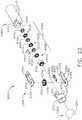
- a surgical instrument systemis depicted in FIG. 1 .
- the surgical instrument systemcomprises a handle assembly 1000 which is selectively usable with a shaft assembly 2000, a shaft assembly 3000, a shaft assembly 4000, a shaft assembly 5000, and/or any other suitable shaft assembly.
- the shaft assembly 2000is attached to the handle assembly 1000 in FIG. 2 and the shaft assembly 4000 is attached to the handle assembly 1000 in FIG. 45 .
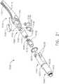
- the shaft assembly 2000comprises a proximal portion 2100, an elongate shaft 2200 extending from the proximal portion 2100, a distal attachment portion 2400, and an articulation joint 2300 rotatably connecting the distal attachment portion 2400 to the elongate shaft 2200.
- the shaft assembly 2000further comprises a replaceable end effector assembly 7000 attached to the distal attachment portion 2400.
- the replaceable end effector assembly 7000comprises a jaw assembly 7100 configured to be opened and closed to clamp and/or manipulate the tissue of a patient.
- the end effector assembly 7000can be articulated about the articulation joint 2300 and/or rotated relative to the distal attachment portion 2400 about a longitudinal axis to better position the jaw assembly 7100 within the patient, as described in greater detail further below.
- the handle assembly 1000comprises, among other things, a drive module 1100.
- the drive module 1100comprises a distal mounting interface which permits a clinician to selectively attach one of the shaft assemblies 2000, 3000, 4000, and 5000, for example, to the drive module 1100.
- each of the shaft assemblies 2000, 3000, 4000, and 5000comprises an identical, or an at least similar, proximal mounting interface which is configured to engage the distal mounting interface of the drive module 1100.
- the mounting interface of the drive module 1100mechanically secures and electrically couples the selected shaft assembly to the drive module 1100.
- the drive module 1100further comprises at least one electric motor, one or more controls and/or displays, and a controller configured to operate the electric motor- the rotational output of which is transmitted to a drive system of the shaft assembly attached to the drive module 1100.
- the drive module 1100is usable with one ore more power modules, such as power modules 1200 and 1300, for example, which are operably attachable to the drive module 1100 to supply power thereto.
- the handle drive module 1100comprises a housing 1110, a first module connector 1120, and a second module connector 1120'.
- the power module 1200comprises a housing 1210, a connector 1220, one or more release latches 1250, and one or more batteries 1230.
- the connector 1220is configured to be engaged with the first module connector 1120 of the drive module 1100 in order to attach the power module 1200 to the drive module 1100.
- the connector 1220comprises one or more latches 1240 which mechanically couple and fixedly secure the housing 1210 of the power module 1200 to the housing 1110 of the drive module 1100.
- the latches 1240are movable into disengaged positions when the release latches 1250 are depressed so that the power module 1200 can be detached from the drive module 1100.
- the connector 1220also comprises one or more electrical contacts which place the batteries 1230, and/or an electrical circuit including the batteries 1230, in electrical communication with an electrical circuit in the drive module 1100.
- the power module 1300comprises a housing 1310, a connector 1320, one or more release latches 1350, and one or more batteries 1330 ( FIG. 47 ).
- the connector 1320is configured to be engaged with the second module connector 1120' of the drive module 1100 to attach the power module 1300 to the drive module 1100.
- the connector 1320comprises one or more latches 1340 which mechanically couple and fixedly secure the housing 1310 of the power module 1300 to the housing 1110 of the drive module 1100.
- the latches 1340are movable into disengaged positions when the release latches 1350 are depressed so that the power module 1300 can be detached from the drive module 1100.
- the connector 1320also comprises one or more electrical contacts which place the batteries 1330 of the power module 1300, and/or an electrical power circuit including the batteries 1330, in electrical communication with an electrical power circuit in the drive module 1100.
- the power module 1200when attached to the drive module 1100, comprises a pistol grip which can allow a clinician to hold the handle 1000 in a manner which places the drive module 1100 on top of the clinician's hand.
- the power module 1300when attached to the drive module 1100, comprises an end grip which allows a clinician to hold the handle 1000 like a wand.
- the power module 1200is longer than the power module 1300, although the power modules 1200 and 1300 can comprise any suitable length.
- the power module 1200has more battery cells than the power module 1300 and can suitably accommodate these additional battery cells owing to its length.
- the power module 1200can provide more power to the drive module 1100 than the power module 1300 while, in some instances, the power module 1200 can provide power for a longer period of time.
- the housing 1110 of the drive module 1100comprises keys, and/or any other suitable features, which prevent the power module 1200 from being connected to the second module connector 1120' and, similarly, prevent the power module 1300 from being connected to the first module connector 1120.
- Such an arrangementcan assure that the longer power module 1200 is used in the pistol grip arrangement and that the shorter power module 1300 is used in the wand grip arrangement.
- the power module 1200 and the power module 1300can be selectively coupled to the drive module 1100 at either the first module connector 1120 or the second module connector 1120'. Such embodiments provide a clinician with more options to customize the handle 1000 in a manner suitable to them.
- the power module 1200can be in the way when the shaft assembly 4000, for example, is attached to the drive module 1100.
- both of the power modules 1200 and 1300can be operably coupled to the drive module 1100 at the same time.
- the drive module 1100can have access to power provided by both of the power modules 1200 and 1300.
- a cliniciancan switch between a pistol grip and a wand grip when both of the power modules 1200 and 1300 are attached to the drive module 1100.
- such an arrangementallows the power module 1300 to act as a counterbalance to a shaft assembly, such as shaft assemblies 2000, 3000, 4000, or 5000, for example, attached to the drive module 1100.
- the handle drive module 1100further comprises a frame 1500, a motor assembly 1600, a drive system 1700 operably engaged with the motor assembly 1600, and a control system 1800.
- the frame 1500comprises an elongate shaft that extends through the motor assembly 1600.
- the elongate shaftcomprises a distal end 1510 and electrical contacts, or sockets, 1520 defined in the distal end 1510.
- the electrical contacts 1520are in electrical communication with the control system 1800 of the drive module 1100 via one or more electrical circuits and are configured to convey signals and/or power between the control system 1800 and the shaft assembly, such as the shaft assembly 2000, 3000, 4000, or 5000, for example, attached to the drive module 1100.
- the control system 1800comprises a printed circuit board (PCB) 1810, at least one microprocessor 1820, and at least one memory device 1830.
- the board 1810can be rigid and/or flexible and can comprise any suitable number of layers.
- the microprocessor 1820 and the memory device 1830are part of a control circuit defined on the board 1810 which controls the operation of the motor assembly 1600, as described in greater detail below.
- the motor assembly 1600comprises an electric motor 1610 including a housing 1620, a drive shaft 1630, and a gear reduction system.
- the electric motor 1610further comprises a stator including windings 1640 and a rotor including magnetic elements 1650.
- the stator windings 1640are supported in the housing 1620 and the rotor magnetic elements 1650 are mounted to the drive shaft 1630.
- the drive shaft 1630is rotated about a longitudinal axis.
- the drive shaft 1630is operably engaged with a first planetary gear system 1660 which includes a central sun gear and several planetary gears operably intermeshed with the sun gear.
- the sun gear of the first planetary gear system 1660is fixedly mounted to the drive shaft 1630 such that it rotates with the drive shaft 1630.
- the planetary gears of the first planetary gear system 1660are rotatably mounted to the sun gear of a second planetary gear system 1670 and, also, intermeshed with a geared or splined inner surface 1625 of the motor housing 1620.
- the rotation of the first sun gearrotates the first planetary gears which rotate the second sun gear.
- the second planetary gear system 1670further comprises planetary gears 1665 ( FIG. 13 ) which drive a third planetary gear system and, ultimately, the drive shaft 1710.
- the planetary gear systems 1660, 1670, and 1680co-operate to gear down the speed applied to the drive shaft 1710 by the motor shaft 1620.
- Various alternative embodimentsare envisioned without a speed reduction system. Such embodiments are suitable when it is desirable to drive the end effector functions quickly.
- the drive shaft 1630comprises an aperture, or hollow core, extending therethrough through which wires and/or electrical circuits can extend.
- the control system 1800is in communication with the motor assembly 1600 and the electrical power circuit of the drive module 1100.
- the control system 1800is configured to control the power delivered to the motor assembly 1600 from the electrical power circuit.
- the electrical power circuitis configured to supply a constant, or at least nearly constant, direct current (DC) voltage. In at least one instance, the electrical power circuit supplies 3 VDC to the control system 1800.
- the control system 1800comprises a pulse width modulation (PWM) circuit which is configured to deliver voltage pulses to the motor assembly 1600. The duration or width of the voltage pulses, and/or the duration or width between the voltage pulses, supplied by the PWM circuit can be controlled in order to control the power applied to the motor assembly 1600.
- PWMpulse width modulation
- the PWM circuitcan control the speed of the output shaft of the motor assembly 1600.
- the control system 1800can include a frequency modulation (FM) circuit.
- FMfrequency modulation
- the control system 1800is operable in more than one operating mode and, depending on the operating mode being used, the control system 1800 can operate the motor assembly 1600 at a speed, or a range of speeds, which is determined to be appropriate for that operating mode.
- the drive system 1700comprises a rotatable shaft 1710 comprising a splined distal end 1720 and a longitudinal aperture 1730 defined therein.
- the rotatable shaft 1710is operably mounted to the output shaft of the motor assembly 1600 such that the rotatable shaft 1710 rotates with the motor output shaft.
- the handle frame 1510extends through the longitudinal aperture 1730 and rotatably supports the rotatable shaft 1710. As a result, the handle frame 1510 serves as a bearing for the rotatable shaft 1710.
- the handle frame 1510 and the rotatable shaft 1710extend distally from a mounting interface 1130 of the drive module 1110 and are coupled with corresponding components on the shaft assembly 2000 when the shaft assembly 2000 is assembled to the drive module 1100.
- the shaft assembly 2000further comprises a frame 2500 and a drive system 2700.
- the frame 2500comprises a longitudinal shaft 2510 extending through the shaft assembly 2000 and a plurality of electrical contacts, or pins, 2520 extending proximally from the shaft 2510.
- the electrical contacts 2520 on the shaft frame 2510engage the electrical contacts 1520 on the handle frame 1510 and create electrical pathways therebetween.
- the drive system 2700comprises a rotatable drive shaft 2710 which is operably coupled to the rotatable drive shaft 1710 of the handle 1000 when the shaft assembly 2000 is assembled to the drive module 1100 such that the drive shaft 2710 rotates with the drive shaft 1710.
- the drive shaft 2710comprises a splined proximal end 2720 which mates with the splined distal end 1720 of the drive shaft 1710 such that the drive shafts 1710 and 2710 rotate together when the drive shaft 1710 is rotated by the motor assembly 1600.
- the shaft assembly 2000is assembled to the handle 1000 along a longitudinal axis; however, the operable interconnection between the drive shafts 1710 and 2710 and the electrical interconnection between the frames 1510 and 2510 can comprise any suitable configuration which can allow a shaft assembly to be assembled to the handle 1000 in any suitable manner.
- the mounting interface 1130 of the drive module 1110is configured to be coupled to a corresponding mounting interface on the shaft assemblies 2000, 3000, 4000, and 5000, for example.
- the shaft assembly 2000comprises a mounting interface 2130 configured to be coupled to the mounting interface 1130 of the drive module 1100.
- the proximal portion 2100 of the shaft assembly 2000comprises a housing 2110 which defines the mounting interface 2130.
- the drive module 1100comprises latches 1140 which are configured to releasably hold the mounting interface 2130 of the shaft assembly 2000 against the mounting interface 1130 of the drive module 1100.
- each latch 1140comprises a lock end 1142 and a pivot portion 1144.
- the pivot portion 1144 of each latch 1140is rotatably coupled to the housing 1110 of the drive module 1100 and, when the latches 1140 are rotated outwardly, as mentioned above, the latches 1140 rotate about the pivot portions 1144.
- each latch 1140further comprises a biasing spring 1146 configured to bias the latches 1140 inwardly into a locked position.
- Each biasing spring 1146is compressed between a latch 1140 and the housing 1110 of the drive module 1100 such that the biasing springs 1146 apply biasing forces to the latches 1140; however, such biasing forces are overcome when the latches 1140 are rotated outwardly into their unlocked positions by the shaft assembly 2000. That said, when the latches 1140 rotate outwardly after contacting the mounting interface 2130, the lock ends 1142 of the latches 1140 can enter into latch windows 2140 defined in the mounting interface 2130. Once the lock ends 1142 pass through the latch windows 2140, the springs 1146 can bias the latches 1140 back into their locked positions.
- Each lock end 1142comprises a lock shoulder, or surface, which securely holds the shaft assembly 2000 to the drive module 1100.
- the biasing springs 1146hold the latches 1140 in their locked positions.
- the distal ends 1142are sized and configured to prevent, or at least inhibit, relative longitudinal movement, i.e., translation along a longitudinal axis, between the shaft assembly 2000 and the drive module 1100 when the latches 1140 are in their locked positions.
- the latches 1140 and the latch windows 1240are sized and configured to prevent relative lateral movement, i.e., translation transverse to the longitudinal axis, between the shaft assembly 2000 and the drive module 1100.
- the latches 1140 and the latch windows 2140are sized and configured to prevent the shaft assembly 2000 from rotating relative to the drive module 1100.
- the drive module 1100further comprises release actuators 1150 which, when depressed by a clinician, move the latches 1140 from their locked positions into their unlocked positions.
- the drive module 1100comprises a first release actuator 1150 slideably mounted in an opening defined in the first side of the handle housing 1110 and a second release actuator 1150 slideably mounted in an opening defined in a second, or opposite, side of the handle housing 1110.
- both release actuators 1150typically need to be depressed to completely unlock the shaft assembly 2000 from the drive module 1100 and allow the shaft assembly 2000 to be detached from the drive module 1100. That said, it is possible that the shaft assembly 2000 could be detached from the drive module 1100 by depressing only one release actuator 1150.
- the cliniciancan maneuver the handle 1000 to insert the end effector 7000 into a patient.
- the end effector 7000is inserted into the patient through a trocar and then manipulated in order to position the jaw assembly 7100 of the end effector assembly 7000 relative to the patient's tissue.
- the jaw assembly 7100must be in its closed, or clamped, configuration in order to fit through the trocar.
- the jaw assembly 7100can be opened so that the patient tissue fit between the jaws of the jaw assembly 7100. At such point, the jaw assembly 7100 can be returned to its closed configuration to clamp the patient tissue between the jaws.
- the clamping force applied to the patient tissue by the jaw assembly 7100is sufficient to move or otherwise manipulate the tissue during a surgical procedure. Thereafter, the jaw assembly 7100 can be re-opened to release the patient tissue from the end effector 7000. This process can be repeated until it is desirable to remove the end effector 7000 from the patient. At such point, the jaw assembly 7100 can be returned to its closed configuration and retracted through the trocar.
- Other surgical techniquesare envisioned in which the end effector 7000 is inserted into a patient through an open incision, or without the use of the trocar. In any event, it is envisioned that the jaw assembly 7100 may have to be opened and closed several times throughout a surgical technique.
- the shaft assembly 2000further comprises a clamping trigger system 2600 and a control system 2800.
- the clamping trigger system 2600comprises a clamping trigger 2610 rotatably connected to the proximal housing 2110 of the shaft assembly 2000.
- the clamping trigger 2610actuates the motor 1610 to operate the jaw drive of the end effector 7000 when the clamping trigger 2610 is actuated.
- the clamping trigger 2610comprises an elongate portion which is graspable by the clinician while holding the handle 1000.
- the clamping trigger 2610further comprises a mounting portion 2620 which is pivotably connected to a mounting portion 2120 of the proximal housing 2110 such that the clamping trigger 2610 is rotatable about a fixed, or an at least substantially fixed, axis.
- the closure trigger 2610is rotatable between a distal position and a proximal position, wherein the proximal position of the closure trigger 2610 is closer to the pistol grip of the handle 1000 than the distal position.
- the closure trigger 2610further comprises a tab 2615 extending therefrom which rotates within the proximal housing 2110. When the closure trigger 2610 is in its distal position, the tab 2615 is positioned above, but not in contact with, a switch 2115 mounted on the proximal housing 2110.
- the switch 2115is part of an electrical circuit configured to detect the actuation of the closure trigger 2610 which is in an open condition the closure trigger 2610 is in its open position. When the closure trigger 2610 is moved into its proximal position, the tab 2615 comes into contact with the switch 2115 and closes the electrical circuit.
- the switch 2115can comprise a toggle switch, for example, which is mechanically switched between open and closed states when contacted by the tab 2615 of the closure trigger 2610.
- the switch 2115can comprise a proximity sensor, for example, and/or any suitable type of sensor.
- the switch 2115comprises a Hall Effect sensor which can detect the amount in which the closure trigger 2610 has been rotated and, based on the amount of rotation, control the speed in which the motor 1610 is operated. In such instances, larger rotations of the closure trigger 2610 result in faster speeds of the motor 1610 while smaller rotations result in slower speeds, for example.
- the electrical circuitis in communication with the control system 2800 of the shaft assembly 2000, which is discussed in greater detail below.
- control system 2800 of the shaft assembly 2000comprises a printed circuit board (PCB) 2810, at least one microprocessor 2820, and at least one memory device 2830.
- the board 2810can be rigid and/or flexible and can comprise any suitable number of layers.
- the microprocessor 2820 and the memory device 2830are part of a control circuit defined on the board 2810 which communicates with the control system 1800 of the handle 1000.
- the shaft assembly 2000further comprises a signal communication system 2900 and the handle 1000 further comprises a signal communication system 1900 which are configured to convey data between the shaft control system 2800 and the handle control system 1800.
- the signal communication system 2900is configured to transmit data to the signal communication system 1900 utilizing any suitable analog and/or digital components.
- the communication systems 2900 and 1900can communicate using a plurality of discrete channels which allows the input gates of the microprocessor 1820 to be directly controlled, at least in part, by the output gates of the microprocessor 2820.
- the communication systems 2900 and 1900can utilize multiplexing.
- the control system 2900includes a multiplexing device that sends multiple signals on a carrier channel at the same time in the form of a single, complex signal to a multiplexing device of the control system 1900 that recovers the separate signals from the complex signal.
- the communication system 2900comprises an electrical connector 2910 mounted to the circuit board 2810.
- the electrical connector 2910comprises a connector body and a plurality of electrically-conductive contacts mounted to the connector body.
- the electrically-conductive contactscomprise male pins, for example, which are soldered to electrical traces defined in the circuit board 2810. In other instances, the male pins can be in communication with circuit board traces through zero-insertion-force (ZIF) sockets, for example.
- the communication system 1900comprises an electrical connector 1910 mounted to the circuit board 1810.
- the electrical connector 1910comprises a connector body and a plurality of electrically-conductive contacts mounted to the connector body.
- the electrically-conductive contactscomprise female pins, for example, which are soldered to electrical traces defined in the circuit board 1810.
- the female pinscan be in communication with circuit board traces through zero-insertion-force (ZIF) sockets, for example.
- ZIFzero-insertion-force
- the electrical connector 2910is operably coupled to the electrical connector 1910 such that the electrical contacts form electrical pathways therebetween.
- the connectors 1910 and 2910can comprise any suitable electrical contacts.
- the communication systems 1900 and 2900can communicate with one another in any suitable manner. In various instances, the communication systems 1900 and 2900 communicate wirelessly. In at least one such instance, the communication system 2900 comprises a wireless signal transmitter and the communication system 1900 comprises a wireless signal receiver such that the shaft assembly 2000 can wirelessly communicate data to the handle 1000. Likewise, the communication system 1900 can comprise a wireless signal transmitter and the communication system 2900 can comprise a wireless signal receiver such that the handle 1000 can wirelessly communicate data to the shaft assembly 2000.
- control system 1800 of the handle 1000is in communication with, and is configured to control, the electrical power circuit of the handle 1000.
- the handle control system 1800is also powered by the electrical power circuit of the handle 1000.
- the handle communication system 1900is in signal communication with the handle control system 1800 and is also powered by the electrical power circuit of the handle 1000.
- the handle communication system 1900is powered by the handle electrical power circuit via the handle control system 1800, but could be directly powered by the electrical power circuit.
- the handle communication system 1900is in signal communication with the shaft communication system 2900. That said, the shaft communication system 2900 is also powered by the handle electrical power circuit via the handle communication system 1900.
- the electrical connectors 1910 and 2010connect both one or more signal circuits and one or more power circuits between the handle 1000 and the shaft assembly 2000.
- the shaft communication system 2900is in signal communication with the shaft control system 2800, as discussed above, and is also configured to supply power to the shaft control system 2800.
- the control systems 1800 and 2800 and the communication systems 1900 and 2900are all powered by the electrical power circuit of the handle 1000; however, alternative embodiments are envisioned in which the shaft assembly 2000 comprises its own power source, such as one or more batteries, for example, an and electrical power circuit configured to supply power from the batteries to the handle systems 2800 and 2900.
- the handle control system 1800 and the handle communication system 1900are powered by the handle electrical power system and the shaft control system 2800 and the handle communication system 2900 are powered by the shaft electrical power system.
- the actuation of the clamping trigger 2610is detected by the shaft control system 2800 and communicated to the handle control system 1800 via the communication systems 2900 and 1900.
- the handle control system 1800Upon receiving a signal that the clamping trigger 2610 has been actuated, the handle control system 1800 supplies power to the electric motor 1610 of the motor assembly 1600 to rotate the drive shaft 1710 of the handle drive system 1700, and the drive shaft 2710 of the shaft drive system 2700, in a direction which closes the jaw assembly 7100 of the end effector 7000.
- the mechanism for converting the rotation of the drive shaft 2710 to a closure motion of the jaw assembly 7100is discussed in greater detail below.
- the handle control system 1800cuts the electrical power to the electric motor 1610.
- the handle control system 1800can determine when the jaw assembly 7100 has reached its fully-clamped position in any suitable manner.
- the handle control system 1800can comprise an encoder system which monitors the rotation of, and counts the rotations of, the output shaft of the electric motor 1610 and, once the number of rotations reaches a predetermined threshold, the handle control system 1800 can discontinue supplying power to the electric motor 1610.
- the end effector assembly 7000can comprise one or more sensors configured to detect when the jaw assembly 7100 has reached its fully-clamped position.
- the sensors in the end effector 7000are in signal communication with the handle control system 1800 via electrical circuits extending through the shaft assembly 2000 which can include the electrical contacts 1520 and 2520, for example.
- the switch 2115is opened which is detected by the shaft control system 2800 and communicated to the handle control system 1800 via the communication systems 2900 and 1900.
- the handle control system 1800Upon receiving a signal that the clamping trigger 2610 has been moved out of its actuated position, the handle control system 1800 reverses the polarity of the voltage differential being applied to the electric motor 1610 of the motor assembly 1600 to rotate the drive shaft 1710 of the handle drive system 1700, and the drive shaft 2710 of the shaft drive system 2700, in an opposite direction which, as a result, opens the jaw assembly 7100 of the end effector 7000.
- the handle control system 1800cuts the electrical power to the electric motor 1610.
- the handle control system 1800can determine when the jaw assembly 7100 has reached its fully-open position in any suitable manner. For instance, the handle control system 1800 can utilize the encoder system and/or the one or more sensors described above to determine the configuration of the jaw assembly 7100. In view of the above, the clinician needs to be mindful about holding the clamping trigger 2610 in its actuated position in order to maintain the jaw assembly 7100 in its clamped configuration as, otherwise, the control system 1800 will open jaw assembly 7100. With this in mind, the shaft assembly 2000 further comprises an actuator latch 2630 configured to releasably hold the clamping trigger 2610 in its actuated position to prevent the accidental opening of the jaw assembly 7100. The actuator latch 2630 can be manually released, or otherwise defeated, by the clinician to allow the clamping trigger 2610 to be rotated distally and open the jaw assembly 7100.
- the clamping trigger system 2600further comprises a resilient biasing member, such as a torsion spring, for example, configured to resist the closure of the clamping trigger system 2600.
- a resilient biasing membersuch as a torsion spring, for example, configured to resist the closure of the clamping trigger system 2600.
- the torsion springcan also assist in reducing and/or mitigating sudden movements and/or jitter of the clamping trigger 2610.
- Such a torsion springcan also automatically return the clamping trigger 2610 to its unactuated position when the clamping trigger 2610 is released.
- the actuator latch 2630 discussed abovecan suitably hold the clamping trigger 2610 in its actuated position against the biasing force of the torsion spring.
- the control system 1800operates the electric motor 1610 to open and close the jaw assembly 7100.
- the control system 1800is configured to open and close the jaw assembly 7100 at the same speed.
- the control system 1800applies the same voltage pulses to the electric motor 1610, albeit with different voltage polarities, when opening and closing the jaw assembly 7100.
- the control system 1800can be configured to open and close the jaw assembly 7100 at different speeds.
- the jaw assembly 7100can be closed at a first speed and opened at a second speed which is faster than the first speed.
- the slower closing speedaffords the clinician an opportunity to better position the jaw assembly 7100 while clamping the tissue.
- the control system 1800can open the jaw assembly 7100 at a slower speed.
- control system 1800can decrease the duration of the voltage pulses and/or increase the duration between the voltage pulses to slow down and/or speed up the movement of the jaw assembly 7100.
- control system 1800is configured to interpret the position of the clamping trigger 2610 as a command to position the jaw assembly 7100 in a specific configuration. For instance, the control system 1800 is configured to interpret the proximal-most position of the clamping trigger 2610 as a command to close the jaw assembly 7100 and any other position of the clamping trigger as a command to open the jaw assembly 7100. That said, the control system 1800 can be configured to interpret the position of the clamping trigger 2610 in a proximal range of positions, instead of a single position, as a command to close the jaw assembly 7100. Such an arrangement can allow the jaw assembly 7000 to be better responsive to the clinician's input.
- the range of motion of the clamping trigger 2610is divided into ranges - a proximal range which is interpreted as a command to close the jaw assembly 7100 and a distal range which is interpreted as a command to open the jaw assembly 7100.
- the range of motion of the clamping trigger 2610can have an intermediate range between the proximal range and the distal range.
- the control system 1800can interpret the position of the clamping trigger 2610 as a command to neither open nor close the jaw assembly 7100.
- Such an intermediate rangecan prevent, or reduce the possibility of, jitter between the opening and closing ranges.
- control system 1800can be configured to ignore cumulative commands to open or close the jaw assembly 7100. For instance, if the closure trigger 2610 has already been fully retracted into its proximal-most position, the control assembly 1800 can ignore the motion of the clamping trigger 2610 in the proximal, or clamping, range until the clamping trigger 2610 enters into the distal, or opening, range wherein, at such point, the control system 1800 can then actuate the electric motor 1610 to open the jaw assembly 7100.
- the position of the clamping trigger 2610 within the clamping trigger range, or at least a portion of the clamping trigger rangecan allow the clinician to control the speed of the electric motor 1610 and, thus, the speed in which the jaw assembly 7100 is being opened or closed by the control assembly 1800.
- the sensor 2115comprises a Hall Effect sensor, and/or any other suitable sensor, configured to detect the position of the clamping trigger 2610 between its distal, unactuated position and its proximal, fully-actuated position.
- the Hall Effect sensoris configured to transmit a signal to the handle control system 1800 via the shaft control system 2800 such that the handle control system 1800 can control the speed of the electric motor 1610 in response to the position of the clamping trigger 2610.
- the handle control system 1800controls the speed of the electric motor 1610 proportionately, or in a linear manner, to the position of the clamping trigger 2610. For example, if the clamping trigger 2610 is moved half way through its range, then the handle control system 1800 will operate the electric motor 1610 at half of the speed in which the electric motor 1610 is operated when the clamping trigger 2610 is fully-retracted. Similarly, if the clamping trigger 2610 is moved a quarter way through its range, then the handle control system 1800 will operate the electric motor 1610 at a quarter of the speed in which the electric motor 1610 is operated when the clamping trigger 2610 is fully-retracted.
- the handle control system 1800controls the speed of the electric motor 1610 in a non-linear manner to the position of the clamping trigger 2610.
- the control system 1800operates the electric motor 1610 slowly in the distal portion of the clamping trigger range while quickly accelerating the speed of the electric motor 1610 in the proximal portion of the clamping trigger range.
- the clamping trigger 2610is movable to operate the electric motor 1610 to open or close the jaw assembly 7100 of the end effector 7000.
- the electric motor 1610is also operable to rotate the end effector 7000 about a longitudinal axis and articulate the end effector 7000 relative to the elongate shaft 2200 about the articulation joint 2300 of the shaft assembly 2000.
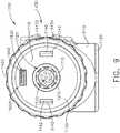
- the drive module 1100comprises an input system 1400 including a rotation actuator 1420 and an articulation actuator 1430.
- the input system 1400further comprises a printed circuit board (PCB) 1410 which is in signal communication with the printed circuit board (PCB) 1810 of the control system 1800.
- PCBprinted circuit board
- the drive module 1100comprises an electrical circuit, such as a flexible wiring harness or ribbon, for example, which permits the input system 1400 to communicate with the control system 1800.
- the rotation actuator 1420is rotatably supported on the housing 1110 and is in signal communication with the input board 1410 and/or control board 1810, as described in greater detail below.
- the articulation actuator 1430is supported by and in signal communication with the input board 1410 and/or control board 1810, as also described in greater detail below.
- the handle housing 1110comprises an annular groove or slot defined therein adjacent the distal mounting interface 1130.
- the rotation actuator 1420comprises an annular ring 1422 rotatably supported within the annular groove and, owing to the configuration of the sidewalls of the annular groove, the annular ring 1422 is constrained from translating longitudinally and/or laterally with respect to the handle housing 1110.
- the annular ring 1422is rotatable in a first, or clockwise, direction and a second, or counter-clockwise direction, about a longitudinal axis extending through the frame 1500 of the drive module 1100.
- the rotation actuator 1420comprises one or more sensors configured to detect the rotation of the annular ring 1422.
- the rotation actuator 1420comprises a first sensor positioned on a first side of the drive module 1100 and a second sensor positioned on a second, or opposite, side of the drive module 1100 and the annular ring 1422 comprises a detectable element which is detectable by the first and second sensors.
- the first sensoris configured to detect when the annular ring 1422 is rotated in the first direction and the second sensor is configured to detect when the annular ring 1422 is rotated in the second direction.
- the handle control system 1800rotates the handle drive shaft 1710, the drive shaft 2710, and the end effector 7000 in the first direction, as described in greater detail below. Similarly, the handle control system 1800 rotates the handle drive shaft 1710, the drive shaft 2710, and the end effector 7000 in the second direction when the second sensor detects that the annular ring 1422 is rotated in the second direction.
- the clamping trigger 2610 and the rotation actuator 1420are both operable to rotate the drive shaft 2710.
- the first and second sensorscomprise switches which are mechanically closable by the detectable element of the annular ring 1422.
- the detectable elementcloses the switch of the first sensor.
- the control system 1800operates the electric motor 1610 to rotate the end effector 7000 in the first direction.
- the detectable elementis disengaged from the first switch and the first switch is re-opened. Once the first switch is re-opened, the control system 1800 cuts the power to the electric motor 1610 to stop the rotation of the end effector 7000.
- the detectable elementcloses the switch of the second sensor when the annular ring 1422 is rotated in the second direction from the center position.
- the control system 1800operates the electric motor 1610 to rotate the end effector 7000 in the second direction.
- the detectable elementis disengaged from the second switch and the second switch is re-opened. Once the second switch is re-opened, the control system 1800 cuts the power to the electric motor 1610 to stop the rotation of the end effector 7000.
- the first and second sensors of the rotation actuator 1420comprise proximity sensors, for example.
- the first and second sensors of the rotation actuator 1420comprise Hall Effect sensors, and/or any suitable sensors, configured to detect the distance between the detectable element of the annular ring 1422 and the first and second sensors. If the first Hall Effect sensor detects that the annular ring 1422 has been rotated in the first direction, then, as discussed above, the control system 1800 will rotate the end effector 7000 in the first direction. In addition, the control system 1800 can rotate the end effector 7000 at a faster speed when the detectable element is closer to the first Hall Effect sensor than when the detectable element is further away from the first Hall Effect sensor.
- the control system 1800will rotate the end effector 7000 in the second direction.
- the control system 1800can rotate the end effector 7000 at a faster speed when the detectable element is closer to the second Hall Effect sensor than when the detectable element is further away from the second Hall Effect sensor.
- the speed in which the end effector 7000 is rotatedis a function of the amount, or degree, in which the annular ring 1422 is rotated.
- the control system 1800is further configured to evaluate the inputs from both the first and second Hall Effect sensors when determining the direction and speed in which to rotate the end effector 7000.
- control system 1800can use the closest Hall Effect sensor to the detectable element of the annular ring 1422 as a primary source of data and the Hall Effect sensor furthest away from the detectable element as a confirmational source of data to double-check the data provided by the primary source of data.
- the control system 1800can further comprise a data integrity protocol to resolve situations in which the control system 1800 is provided with conflicting data.
- the handle control system 1800can enter into a neutral state in which the handle control system 1800 does not rotate the end effector 7000 when the Hall Effect sensors detect that the detectable element is in its center position, or in a position which is equidistant between the first Hall Effect sensor and the second Hall Effect sensor.
- control system 1800can enter into its neutral state when the detectable element is in a central range of positions. Such an arrangement would prevent, or at least reduce the possibility of, rotational jitter when the clinician is not intending to rotate the end effector 7000.
- the rotation actuator 1420can comprise one or more springs configured to center, or at least substantially center, the rotation actuator 1420 when it is released by the clinician.
- the springscan act to shut off the electric motor 1610 and stop the rotation of the end effector 7000.
- the rotation actuator 1420comprises a first torsion spring configured to rotate the rotation actuator 1420 in the first direction and a second torsion spring configured to rotate the rotation actuator 1420 in the second direction.
- the first and second torsion springscan have the same, or at least substantially the same, spring constant such that the forces and/or torques applied by the first and second torsion springs balance, or at least substantially balance, the rotation actuator 1420 in its center position.
- clamping trigger 2610 and the rotation actuator 1420are both operable to rotate the drive shaft 2710 and either, respectively, operate the jaw assembly 7100 or rotate the end effector 7000.
- the system that uses the rotation of the drive shaft 2710 to selectively perform these functionsis described in greater detail below.
- the articulation actuator 1430comprises a first push button 1432 and a second push button 1434.
- the first push button 1432is part of a first articulation control circuit and the second push button 1434 is part of a second articulation circuit of the input system 1400.
- the first push button 1432comprises a first switch that is closed when the first push button 1432 is depressed.
- the handle control system 1800is configured to sense the closure of the first switch and, moreover, the closure of the first articulation control circuit. When the handle control system 1800 detects that the first articulation control circuit has been closed, the handle control system 1800 operates the electric motor 1610 to articulate the end effector 7000 in a first articulation direction about the articulation joint 2300.
- the first articulation control circuitis opened which, once detected by the control system 1800, causes the control system 1800 to cut the power to the electric motor 1610 to stop the articulation of the end effector 7000.
- the articulation range of the end effector 7000is limited and the control system 1800 can utilize the encoder system discussed above for monitoring the rotational output of the electric motor 1610, for example, to monitor the amount, or degree, in which the end effector 7000 is rotated in the first direction.
- the shaft assembly 2000can comprise a first sensor configured to detect when the end effector 7000 has reached the limit of its articulation in the first direction. In any event, when the control system 1800 determines that the end effector 7000 has reached the limit of articulation in the first direction, the control system 1800 can cut the power to the electric motor 1610 to stop the articulation of the end effector 7000.
- the second push button 1434comprises a second switch that is closed when the second push button 1434 is depressed.
- the handle control system 1800is configured to sense the closure of the second switch and, moreover, the closure of the second articulation control circuit.
- the handle control system 1800detects that the second articulation control circuit has been closed, the handle control system 1800 operates the electric motor 1610 to articulate the end effector 7000 in a second direction about the articulation joint 2300.
- the second articulation control circuitis opened which, once detected by the control system 1800, causes the control system 1800 to cut the power to the electric motor 1610 to stop the articulation of the end effector 7000.
- the articulation range of the end effector 7000is limited and the control system 1800 can utilize the encoder system discussed above for monitoring the rotational output of the electric motor 1610, for example, to monitor the amount, or degree, in which the end effector 7000 is rotated in the second direction.
- the shaft assembly 2000can comprise a second sensor configured to detect when the end effector 7000 has reached the limit of its articulation in the second direction. In any event, when the control system 1800 determines that the end effector 7000 has reached the limit of articulation in the second direction, the control system 1800 can cut the power to the electric motor 1610 to stop the articulation of the end effector 7000.
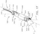
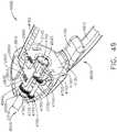
- the end effector 7000is articulatable in a first direction ( FIG. 16 ) and/or a second direction ( FIG. 17 ) from a center, or unarticulated, position ( FIG. 15 ).
- the cliniciancan attempt to re-center the end effector 7000 by using the first and second articulation push buttons 1432 and 1434.
- the clinicianmay struggle to re-center the end effector 7000 as, for instance, the end effector 7000 may not be entirely visible once it is positioned in the patient.
- the end effector 7000may not fit back through a trocar if the end effector 7000 is not re-centered, or at least substantially re-centered.
- the control system 1800is configured to provide feedback to the clinician when the end effector 7000 is moved into its unarticulated, or centered, position.
- the feedbackcomprises audio feedback and the handle control system 1800 can comprise a speaker which emits a sound, such as a beep, for example, when the end effector 7000 is centered.
- the feedbackcomprises visual feedback and the handle control system 1800 can comprise a light emitting diode (LED), for example, positioned on the handle housing 1110 which flashes when the end effector 7000 is centered.
- the feedbackcomprises haptic feedback and the handle control system 1800 can comprise an electric motor comprising an eccentric element which vibrates the handle 1000 when the end effector 7000 is centered.
- Manually re-centering the end effector 7000 in this waycan be facilitated by the control system 1800 slowing the motor 1610 when the end effector 7000 is approaching its centered position.
- the control system 1800slows the articulation of the end effector 7000 when the end effector 7000 is within approximately 5 degrees of center in either direction, for example.
- the handle control system 1800can be configured to re-center the end effector 7000.
- the handle control system 1800can re-center the end effector 7000 when both of the articulation buttons 1432 and 1434 of the articulation actuator 1430 are depressed at the same time.
- the handle control system 1800comprises an encoder system configured to monitor the rotational output of the electric motor 1610, for example, the handle control system 1800 can determine the amount and direction of articulation needed to re-center, or at least substantially re-center, the end effector 7000.
- the input system 1400can comprise a home button, for example, which, when depressed, automatically centers the end effector 7000.
- the elongate shaft 2200 of the shaft assembly 2000comprises an outer housing, or tube, 2210 mounted to the proximal housing 2110 of the proximal portion 2100.
- the outer housing 2210comprises a longitudinal aperture 2230 extending therethrough and a proximal flange 2220 which secures the outer housing 2210 to the proximal housing 2110.
- the frame 2500 of the shaft assembly 2000extends through the longitudinal aperture 2230 of the elongate shaft 2200. More specifically, the shaft 2510 of the shaft frame 2500 necks down into a smaller shaft 2530 which extends through the longitudinal aperture 2230. That said, the shaft frame 2500 can comprise any suitable arrangement.
- the drive system 2700 of the shaft assembly 2000also extends through the longitudinal aperture 2230 of the elongate shaft 2200. More specifically, the drive shaft 2710 of the shaft drive system 2700 necks down into a smaller drive shaft 2730 which extends through the longitudinal aperture 2230. That said, the shaft drive system 2700 can comprise any suitable arrangement.
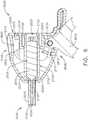
- the outer housing 2210 of the elongate shaft 2200extends to the articulation joint 2300.
- the articulation joint 2300comprises a proximal frame 2310 mounted to the outer housing 2210 such that there is little, if any, relative translation and/or rotation between the proximal frame 2310 and the outer housing 2210.
- the proximal frame 2310comprises an annular portion 2312 mounted to the sidewall of the outer housing 2210 and tabs 2314 extending distally from the annular portion 2312.
- the articulation joint 2300further comprises links 2320 and 2340 which are rotatably mounted to the frame 2310 and mounted to an outer housing 2410 of the distal attachment portion 2400.
- the link 2320comprises a distal end 2322 mounted to the outer housing 2410. More specifically, the distal end 2322 of the link 2320 is received and fixedly secured within a mounting slot 2412 defined in the outer housing 2410.
- the link 2340comprises a distal end 2342 mounted to the outer housing 2410. More specifically, the distal end 2342 of the link 2340 is received and fixedly secured within a mounting slot defined in the outer housing 2410.
- the link 2320comprises a proximal end 2324 rotatably coupled to a tab 2314 of the proximal articulation frame 2310.
- a pinextends through apertures defined in the proximal end 2324 and the tab 2314 to define a pivot axis therebetween.
- the link 2340comprises a proximal end 2344 rotatably coupled to a tab 2314 of the proximal articulation frame 2310.
- a pinextends through apertures defined in the proximal end 2344 and the tab 2314 to define a pivot axis therebetween.
- the outer housing 2410 of the distal attachment portion 2400comprises a longitudinal aperture 2430 extending therethrough.
- the longitudinal aperture 2430is configured to receive a proximal attachment portion 7400 of the end effector 7000.
- the end effector 7000comprises an outer housing 6230 which is closely received within the longitudinal aperture 2430 of the distal attachment portion 2400 such that there is little, if any, relative radial movement between the proximal attachment portion 7400 of the end effector 7000 and the distal attachment portion 2400 of the shaft assembly 2000.
- the proximal attachment portion 7400further comprises an annular array of lock notches 7410 defined on the outer housing 6230 which is releasably engaged by an end effector lock 6400 in the distal attachment portion 2400 of the shaft assembly 2000.
- the end effector lock 6400prevents, or at least inhibits, relative longitudinal movement between the proximal attachment portion 7400 of the end effector 7000 and the distal attachment portion 2400 of the shaft assembly 2000.
- the outer housing 6230 of the end effector 7000is closely received within the longitudinal aperture 2430 defined in the distal attachment portion 2400 of the shaft assembly 2000.
- the outer housing 6230further comprises an annular slot, or recess, 6270 defined therein which is configured to receive an O-ring 6275 therein.
- the O-ring 6275is compressed between the outer housing 6230 and the sidewall of the longitudinal aperture 2430 when the end effector 7000 is inserted into the distal attachment portion 2400.
- the O-ring 6275is configured to resist, but permit, relative rotation between the end effector 7000 and the distal attachment portion 2400 such that the O-ring 6275 can prevent, or reduce the possibility of, unintentional relative rotation between the end effector 7000 and the distal attachment portion 2400.
- the O-ring 6275can provide a seal between the end effector 7000 and the distal attachment portion 2400 to prevent, or at least reduce the possibility of, fluid ingress into the shaft assembly 2000, for example.
- the jaw assembly 7100 of the end effector 7000comprises a first jaw 7110 and a second jaw 7120.
- Each jaw 7110, 7120comprises a distal end which is configured to assist a clinician in dissecting tissue with the end effector 7000.
- Each jaw 7110, 7120further comprises a plurality of teeth which are configured to assist a clinician in grasping and holding onto tissue with the end effector 7000.
- each jaw 7110, 7120comprises a proximal end, i.e., proximal ends 7115, 7125, respectively, which rotatably connect the jaws 7110, 7120 together.
- Each proximal end 7115, 7125comprises an aperture extending therethrough which is configured to closely receive a pin 7130 therein.
- the pin 7130comprises a central body 7135 closely received within the apertures defined in the proximal ends 7115, 7125 of the jaws 7110, 7120 such that there is little, if any, relative translation between the jaws 7110, 7120 and the pin 7130.
- the pin 7130defines a jaw axis J about which the jaws 7110, 7120 can be rotated and, also, rotatably mounts the jaws 7110, 7120 to the outer housing 6230 of the end effector 7000.
- the outer housing 6230comprises distally-extending tabs 6235 having apertures defined therein which are also configured to closely receive the pin 7130 such that the jaw assembly 7100 does not translate relative to a shaft portion 7200 of the end effector 7000.
- the pin 7130further comprises enlarged ends which prevent the jaws 7110, 7120 from becoming detached from the pin 7130 and also prevents the jaw assembly 7100 from becoming detached from the shaft portion 7200. This arrangement defines a rotation joint 7300.
- the jaws 7110 and 7120are rotatable between their open and closed positions by a jaw assembly drive including drive links 7140, a drive nut 7150, and a drive screw 6130.
- the drive screw 6130is selectively rotatable by the drive shaft 2730 of the shaft drive system 2700.
- the drive screw 6130comprises an annular flange 6132 which is closely received within a slot, or groove, 6232 ( FIG. 25 ) defined in the outer housing 6230 of the end effector 7000.
- the sidewalls of the slot 6232are configured to prevent, or at least inhibit, longitudinal and/or radial translation between the drive screw 6130 and the outer housing 6230, but yet permit relative rotational motion between the drive screw 6130 and the outer housing 6230.
- the drive screw 6130further comprises a threaded end 6160 which is threadably engaged with a threaded aperture 7160 defined in the drive nut 7150.
- the drive nut 7150is constrained from rotating with the drive screw 6130 and, as a result, the drive nut 7150 is translated when the drive screw 6130 is rotated. In use, the drive screw 6130 is rotated in a first direction to displace the drive nut 7150 proximally and in a second, or opposite, direction to displace the drive nut 7150 distally.
- the drive nut 7150further comprises a distal end 7155 comprising an aperture defined therein which is configured to closely receive pins 7145 extending from the drive links 7140.
- a first drive link 7140is attached to one side of the distal end 7155 and a second drive link 7140 is attached to the opposite side of the distal end 7155.
- the first drive link 7140comprises another pin 7145 extending therefrom which is closely received in an aperture defined in the proximal end 7115 of the first jaw 7110 and, similarly, the second drive link 7140 comprises another pin extending therefrom which is closely received in an aperture defined in the proximal end 7125 of the second jaw 7120.
- the drive links 7140operably connect the jaws 7110 and 7120 to the drive nut 7150.
- the jaws 7110, 7120are rotated into the closed, or clamped, configuration.
- the jaws 7110, 7120are rotated into their open configuration when the drive nut 7150 is driven distally by the drive screw 6130.
- control system 1800is configured to actuate the electric motor 1610 to perform three different end effector functions - clamping/opening the jaw assembly 7100 ( FIGS. 14 and 15 ), rotating the end effector 7000 about a longitudinal axis ( FIGS. 18 and 19 ), and articulating the end effector 7000 about an articulation axis ( FIGS. 16 and 17 ).
- the control system 1800is configured to operate a transmission 6000 to selectively perform these three end effector functions.
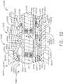
- the transmission 6000comprises a first clutch system 6100 configured to selectively transmit the rotation of the drive shaft 2730 to the drive screw 6130 of the end effector 7000 to open or close the jaw assembly 7100, depending on the direction in which the drive shaft 2730 is rotated.
- the transmission 6000further comprises a second clutch system 6200 configured to selectively transmit the rotation of the drive shaft 2730 to the outer housing 6230 of the end effector 7000 to rotate the end effector 7000 about the longitudinal axis L.
- the transmission 6000also comprises a third clutch system 6300 configured to selectively transmit the rotation of the drive shaft 2730 to the articulation joint 2300 to articulate the distal attachment portion 2400 and the end effector 7000 about the articulation axis A.
- the clutch systems 6100, 6200, and 6300are in electrical communication with the control system 1800 via electrical circuits extending through the shaft 2510, the connector pins 2520, the connector pins 1520, and the shaft 1510, for example.
- each of these clutch control circuitscomprises two connector pins 2520 and two connector pins 1520, for example.
- the shaft 2510 and/or the shaft 1510comprise a flexible circuit including electrical traces which form part of the clutch control circuits.
- the flexible circuitcan comprise a ribbon, or substrate, with conductive pathways defined therein and/or thereon.
- the flexible circuitcan also comprise sensors and/or any solid state component, such as signal smoothing capacitors, for example, mounted thereto.
- each of the conductive pathwayscan comprise one or more signal smoothing capacitors which can, among other things, even out fluctuations in signals transmitted through the conductive pathways.
- the flexible circuitcan be coated with at least one material, such as an elastomer, for example, which can seal the flexible circuit against fluid ingress.
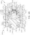
- the first clutch system 6100comprises a first clutch 6110, an expandable first drive ring 6120, and a first electromagnetic actuator 6140.
- the first clutch 6110comprises an annular ring and is slideably disposed on the drive shaft 2730.
- the first clutch 6110is comprised of a magnetic material and is movable between a disengaged, or unactuated, position ( FIG. 28 ) and an engaged, or actuated, position ( FIG. 29 ) by electromagnetic fields EF generated by the first electromagnetic actuator 6140.
- the first clutch 6110is at least partially comprised of iron and/or nickel, for example.
- the first clutch 6110comprises a permanent magnet. As illustrated in FIG.
- the drive shaft 2730comprises one or more longitudinal key slots 6115 defined therein which are configured to constrain the longitudinal movement of the clutch 6110 relative to the drive shaft 2730. More specifically, the clutch 6110 comprises one or more keys extending into the key slots 6115 such that the distal ends of the key slots 6115 stop the distal movement of the clutch 6110 and the proximal ends of the key slots 6115 stop the proximal movement of the clutch 6110.
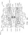
- the first clutch 6110When the first clutch 6110 is in its disengaged position ( FIG. 28 ), the first clutch 6110 rotates with the drive shaft 2130 but does not transmit rotational motion to the first drive ring 6120. As can be seen in FIG. 28 , the first clutch 6110 is separated from, or not in contact with, the first drive ring 6120. As a result, the rotation of the drive shaft 2730 and the first clutch 6110 is not transmitted to the drive screw 6130 when the first clutch assembly 6100 is in its disengaged state. When the first clutch 6110 is in its engaged position ( FIG. 29 ), the first clutch 6110 is engaged with the first drive ring 6120 such that the first drive ring 6120 is expanded, or stretched, radially outwardly into contact with the drive screw 6130.
- the first drive ring 6120comprises an elastomeric band, for example.
- the first drive ring 6120is compressed against an annular inner sidewall 6135 of the drive screw 6130.
- the rotation of the drive shaft 2730 and the first clutch 6110is transmitted to the drive screw 6130 when the first clutch assembly 6100 is in its engaged state.
- the first clutch assembly 6100can move the jaw assembly 7100 into its open and closed configurations when the first clutch assembly 6100 is in its engaged state.
- the first electromagnetic actuator 6140is configured to generate magnetic fields to move the first clutch 6110 between its disengaged ( FIG. 28 ) and engaged ( FIG. 29 ) positions.
- the first electromagnetic actuator 6140is configured to emit a magnetic field EF L which repulses, or drives, the first clutch 6110 away from the first drive ring 6120 when the first clutch assembly 6100 is in its disengaged state.
- the first electromagnetic actuator 6140comprises one or more wound coils in a cavity defined in the shaft frame 2530 which generate the magnetic field EF L when current flows in a first direction through a first electrical clutch circuit including the wound coils.
- the control system 1800is configured to apply a first voltage polarity to the first electrical clutch circuit to create the current flowing in the first direction.
- the control system 1800can continuously apply the first voltage polarity to the first electric shaft circuit to continuously hold the first clutch 6110 in its disengaged position. While such an arrangement can prevent the first clutch 6110 from unintentionally engaging the first drive ring 6120, such an arrangement can also consume a lot of power.
- the control system 1800can apply the first voltage polarity to the first electrical clutch circuit for a sufficient period of time to position the first clutch 6110 in its disengaged position and then discontinue applying the first voltage polarity to the first electric clutch circuit, thereby resulting in a lower consumption of power.
- the first clutch assembly 6100further comprises a first clutch lock 6150 mounted in the drive screw 6130 which is configured to releasably hold the first clutch 6110 in its disengaged position.
- the first clutch lock 6150is configured to prevent, or at least reduce the possibility of, the first clutch 6110 from becoming unintentionally engaged with the first drive ring 6120.
- the first clutch lock 6150interferes with the free movement of the first clutch 6110 and holds the first clutch 6110 in position via a friction force and/or an interference force therebetween.
- the first clutch lock 6150comprises an elastomeric plug, seat, or detent, comprised of rubber, for example.
- the first clutch lock 6150comprises a permanent magnet which holds the first clutch 6110 in its disengaged position by an electromagnetic force.
- the first electromagnetic actuator 6140can apply an electromagnetic pulling force to the first clutch 6110 that overcomes these forces, as described in greater detail below.
- the first electromagnetic actuator 6140is configured to emit a magnetic field EF D which pulls, or drives, the first clutch 6110 toward the first drive ring 6120 when the first clutch assembly 6100 is in its engaged state.
- the coils of the first electromagnetic actuator 6140generate the magnetic field EF D when current flows in a second, or opposite, direction through the first electrical clutch circuit.
- the control system 1800is configured to apply an opposite voltage polarity to the first electrical clutch circuit to create the current flowing in the opposite direction.
- the control system 1800can continuously apply the opposite voltage polarity to the first electrical clutch circuit to continuously hold the first clutch 6110 in its engaged position and maintain the operable engagement between the first drive ring 6120 and the drive screw 6130.
- the first clutch 6110can be configured to become wedged within the first drive ring 6120 when the first clutch 6110 is in its engaged position and, in such instances, the control system 1800 may not need to continuously apply a voltage polarity to the first electrical clutch circuit to hold the first clutch assembly 6100 in its engaged state. In such instances, the control system 1800 can discontinue applying the voltage polarity once the first clutch 6110 has been sufficiently wedged in the first drive ring 6120.
- the first clutch lock 6150is also configured to lockout the jaw assembly drive when the first clutch 6110 is in its disengaged position. More specifically, referring again to FIG. 28 , the first clutch 6110 pushes the first clutch lock 6150 in the drive screw 6130 into engagement with the outer housing 6230 of the end effector 7000 when the first clutch 6110 is in its disengaged position such that the drive screw 6130 does not rotate, or at least substantially rotate, relative to the outer housing 6230.
- the outer housing 6230comprises a slot 6235 defined therein which is configured to receive the first clutch lock 6150.
- the first clutch 6110is no longer engaged with the first clutch lock 6150 and, as a result, the first clutch lock 6150 is no longer biased into engagement with the outer housing 6230 and the drive screw 6130 can rotate freely with respect to the outer housing 6230.
- the first clutch 6110can do at least two things - operate the jaw drive when the first clutch 6110 is in its engaged position and lock out the jaw drive when the first clutch 6110 is in its disengaged position.
- the threads of the threaded portions 6160 and 7160can be configured to prevent, or at least resist, backdriving of the jaw drive.
- the thread pitch and/or angle of the threaded portions 6160 and 7160can be selected to prevent the backdriving, or unintentional opening, of the jaw assembly 7100.
- the second clutch system 6200comprises a second clutch 6210, an expandable second drive ring 6220, and a second electromagnetic actuator 6240.
- the second clutch 6210comprises an annular ring and is slideably disposed on the drive shaft 2730.
- the second clutch 6210is comprised of a magnetic material and is movable between a disengaged, or unactuated, position ( FIG. 30 ) and an engaged, or actuated, position ( FIG. 31 ) by electromagnetic fields EF generated by the second electromagnetic actuator 6240.
- the second clutch 6210is at least partially comprised of iron and/or nickel, for example.
- the second clutch 6210comprises a permanent magnet. As illustrated in FIG.
- the drive shaft 2730comprises one or more longitudinal key slots 6215 defined therein which are configured to constrain the longitudinal movement of the second clutch 6210 relative to the drive shaft 2730. More specifically, the second clutch 6210 comprises one or more keys extending into the key slots 6215 such that the distal ends of the key slots 6215 stop the distal movement of the second clutch 6210 and the proximal ends of the key slots 6215 stop the proximal movement of the second clutch 6210.
- the second clutch 6210When the second clutch 6210 is in its disengaged position, referring to FIG. 30 , the second clutch 6210 rotates with the drive shaft 2730 but does not transmit rotational motion to the second drive ring 6220. As can be seen in FIG. 30 , the second clutch 6210 is separated from, or not in contact with, the second drive ring 6220. As a result, the rotation of the drive shaft 2730 and the second clutch 6210 is not transmitted to the outer housing 6230 of the end effector 7000 when the second clutch assembly 6200 is in its disengaged state. When the second clutch 6210 is in its engaged position ( FIG.
- the second clutch 6210is engaged with the second drive ring 6220 such that the second drive ring 6220 is expanded, or stretched, radially outwardly into contact with the outer housing 6230.
- the second drive ring 6220comprises an elastomeric band, for example.
- the second drive ring 6220is compressed against an annular inner sidewall 7415 of the outer housing 6230.
- the rotation of the drive shaft 2730 and the second clutch 6210is transmitted to the outer housing 6230 when the second clutch assembly 6200 is in its engaged state.
- the second clutch assembly 6200can rotate the end effector 7000 in a first direction or a second direction about the longitudinal axis L when the second clutch assembly 6200 is in its engaged state.
- the second electromagnetic actuator 6240is configured to generate magnetic fields to move the second clutch 6210 between its disengaged ( FIG. 30 ) and engaged ( FIG. 31 ) positions.
- the second electromagnetic actuator 6240is configured to emit a magnetic field EF L which repulses, or drives, the second clutch 6210 away from the second drive ring 6220 when the second clutch assembly 6200 is in its disengaged state.
- the second electromagnetic actuator 6240comprises one or more wound coils in a cavity defined in the shaft frame 2530 which generate the magnetic field EF L when current flows in a first direction through a second electrical clutch circuit including the wound coils.
- the control system 1800is configured to apply a first voltage polarity to the second electrical clutch circuit to create the current flowing in the first direction.
- the control system 1800can continuously apply the first voltage polarity to the second electric clutch circuit to continuously hold the second clutch 6120 in its disengaged position. While such an arrangement can prevent the second clutch 6210 from unintentionally engaging the second drive ring 6220, such an arrangement can also consume a lot of power.
- the control system 1800can apply the first voltage polarity to the second electrical clutch circuit for a sufficient period of time to position the second clutch 6210 in its disengaged position and then discontinue applying the first voltage polarity to the second electric clutch circuit, thereby resulting in a lower consumption of power.
- the second clutch assembly 6200further comprises a second clutch lock 6250 mounted in the outer housing 6230 which is configured to releasably hold the second clutch 6210 in its disengaged position.
- the second clutch lock 6250can prevent, or at least reduce the possibility of, the second clutch 6210 from becoming unintentionally engaged with the second drive ring 6220.
- the second clutch lock 6250interferes with the free movement of the second clutch 6210 and holds the second clutch 6210 in position via a friction and/or interference force therebetween.
- the second clutch lock 6250comprises an elastomeric plug, seat, or detent, comprised of rubber, for example.
- the second clutch lock 6250comprises a permanent magnet which holds the second clutch 6210 in its disengaged position by an electromagnetic force. That said, the second electromagnetic actuator 6240 can apply an electromagnetic pulling force to the second clutch 6210 that overcomes these forces, as described in greater detail below.
- the second electromagnetic actuator 6240is configured to emit a magnetic field EF D which pulls, or drives, the second clutch 6210 toward the second drive ring 6220 when the second clutch assembly 6200 is in its engaged state.
- the coils of the second electromagnetic actuator 6240generate the magnetic field EF D when current flows in a second, or opposite, direction through the second electrical shaft circuit.
- the control system 1800is configured to apply an opposite voltage polarity to the second electrical shaft circuit to create the current flowing in the opposite direction.
- the control system 1800can continuously apply the opposite voltage polarity to the second electric shaft circuit to continuously hold the second clutch 6210 in its engaged position and maintain the operable engagement between the second drive ring 6220 and the outer housing 6230.
- the second clutch 6210can be configured to become wedged within the second drive ring 6220 when the second clutch 6210 is in its engaged position and, in such instances, the control system 1800 may not need to continuously apply a voltage polarity to the second shaft electrical circuit to hold the second clutch assembly 6200 in its engaged state. In such instances, the control system 1800 can discontinue applying the voltage polarity once the second clutch 6210 has been sufficiently wedged in the second drive ring 6220.
- the second clutch lock 6250is also configured to lockout the rotation of the end effector 7000 when the second clutch 6210 is in its disengaged position. More specifically, referring again to FIG. 30 , the second clutch 6210 pushes the second clutch lock 6250 in the outer shaft 6230 into engagement with the articulation link 2340 when the second clutch 6210 is in its disengaged position such that the end effector 7000 does not rotate, or at least substantially rotate, relative to the distal attachment portion 2400 of the shaft assembly 2000. As illustrated in FIG. 27 , the second clutch lock 6250 is positioned or wedged within a slot, or channel, 2345 defined in the articulation link 2340 when the second clutch 6210 is in its disengaged position.
- the second clutch 6210can do at least two things - operate the end effector rotation drive when the second clutch 6210 is in its engaged position and lock out the end effector rotation drive when the second clutch 6210 is in its disengaged position.
- the shaft assembly 2000further comprises an articulation drive system configured to articulate the distal attachment portion 2400 and the end effector 7000 about the articulation joint 2300.
- the articulation drive systemcomprises an articulation drive 6330 rotatably supported within the distal attachment portion 2400. That said, the articulation drive 6330 is closely received within the distal attachment portion 2400 such that the articulation drive 6330 does not translate, or at least substantially translate, relative to the distal attachment portion 2400.
- the articulation drive system of the shaft assembly 2000further comprises a stationary gear 2330 fixedly mounted to the articulation frame 2310.
- the stationary gear 2330is fixedly mounted to a pin connecting a tab 2314 of the articulation frame 2310 and the articulation link 2340 such that the stationary gear 2330 does not rotate relative to the articulation frame 2310.
- the stationary gear 2330comprises a central body 2335 and an annular array of stationary teeth 2332 extending around the perimeter of the central body 2335.
- the articulation drive 6330comprises an annular array of drive teeth 6332 which is meshingly engaged with the stationary teeth 2332. When the articulation drive 6330 is rotated, the articulation drive 6330 pushes against the stationary gear 2330 and articulates the distal attachment portion 2400 of the shaft assembly 2000 and the end effector 7000 about the articulation joint 2300.
- the third clutch system 6300comprises a third clutch 6310, an expandable third drive ring 6320, and a third electromagnetic actuator 6340.
- the third clutch 6310comprises an annular ring and is slideably disposed on the drive shaft 2730.
- the third clutch 6310is comprised of a magnetic material and is movable between a disengaged, or unactuated, position ( FIG. 32 ) and an engaged, or actuated, position ( FIG. 33 ) by electromagnetic fields EF generated by the third electromagnetic actuator 6340.
- the third clutch 6310is at least partially comprised of iron and/or nickel, for example.
- the third clutch 6310comprises a permanent magnet. As illustrated in FIG.
- the drive shaft 2730comprises one or more longitudinal key slots 6315 defined therein which are configured to constrain the longitudinal movement of the third clutch 6310 relative to the drive shaft 2730. More specifically, the third clutch 6310 comprises one or more keys extending into the key slots 6315 such that the distal ends of the key slots 6315 stop the distal movement of the third clutch 6310 and the proximal ends of the key slots 6315 stop the proximal movement of the third clutch 6310.
- the third clutch 6310When the third clutch 6310 is in its disengaged position, referring to FIG. 32 , the third clutch 6310 rotates with the drive shaft 2730 but does not transmit rotational motion to the third drive ring 6320. As can be seen in FIG. 32 , the third clutch 6310 is separated from, or not in contact with, the third drive ring 6320. As a result, the rotation of the drive shaft 2730 and the third clutch 6310 is not transmitted to the articulation drive 6330 when the third clutch assembly 6300 is in its disengaged state. When the third clutch 6310 is in its engaged position, referring to FIG.
- the third clutch 6310is engaged with the third drive ring 6320 such that the third drive ring 6320 is expanded, or stretched, radially outwardly into contact with the articulation drive 6330.
- the third drive ring 6320comprises an elastomeric band, for example.
- the third drive ring 6320is compressed against an annular inner sidewall 6335 of the articulation drive 6330.
- the rotation of the drive shaft 2730 and the third clutch 6310is transmitted to the articulation drive 6330 when the third clutch assembly 6300 is in its engaged state.
- the third clutch assembly 6300can articulate the distal attachment portion 2400 of the shaft assembly 2000 and the end effector 7000 in a first or second direction about the articulation joint 2300.
- the third electromagnetic actuator 6340is configured to generate magnetic fields to move the third clutch 6310 between its disengaged ( FIG. 32 ) and engaged ( FIG. 33 ) positions.
- the third electromagnetic actuator 6340is configured to emit a magnetic field EF L which repulses, or drives, the third clutch 6310 away from the third drive ring 6320 when the third clutch assembly 6300 is in its disengaged state.
- the third electromagnetic actuator 6340comprises one or more wound coils in a cavity defined in the shaft frame 2530 which generate the magnetic field EF L when current flows in a first direction through a third electrical clutch circuit including the wound coils.
- the control system 1800is configured to apply a first voltage polarity to the third electrical clutch circuit to create the current flowing in the first direction.
- the control system 1800can continuously apply the first voltage polarity to the third electric clutch circuit to continuously hold the third clutch 6310 in its disengaged position. While such an arrangement can prevent the third clutch 6310 from unintentionally engaging the third drive ring 6320, such an arrangement can also consume a lot of power.
- the control system 1800can apply the first voltage polarity to the third electrical clutch circuit for a sufficient period of time to position the third clutch 6310 in its disengaged position and then discontinue applying the first voltage polarity to the third electric clutch circuit, thereby resulting in a lower consumption of power.
- the third electromagnetic actuator 6340is configured to emit a magnetic field EF D which pulls, or drives, the third clutch 6310 toward the third drive ring 6320 when the third clutch assembly 6300 is in its engaged state.
- the coils of the third electromagnetic actuator 6340generate the magnetic field EF D when current flows in a second, or opposite, direction through the third electrical clutch circuit.
- the control system 1800is configured to apply an opposite voltage polarity to the third electrical shaft circuit to create the current flowing in the opposite direction.
- the control system 1800can continuously apply the opposite voltage polarity to the third electric shaft circuit to continuously hold the third clutch 6310 in its engaged position and maintain the operable engagement between the third drive ring 6320 and the articulation drive 6330.
- the third clutch 6210can be configured to become wedged within the third drive ring 6320 when the third clutch 6310 is in its engaged position and, in such instances, the control system 1800 may not need to continuously apply a voltage polarity to the third shaft electrical circuit to hold the third clutch assembly 6300 in its engaged state. In such instances, the control system 1800 can discontinue applying the voltage polarity once the third clutch 6310 has been sufficiently wedged in the third drive ring 6320.
- the end effector 7000is articulatable in a first direction or a second direction, depending on the direction in which the drive shaft 2730 is rotated, when the third clutch assembly 6300 is in its engaged state.
- the articulation drive systemfurther comprises a lockout 6350 which prevents, or at least inhibits, the articulation of the distal attachment portion 2400 of the shaft assembly 2000 and the end effector 7000 about the articulation joint 2300 when the third clutch 6310 is in its disengaged position ( FIG. 32 ).
- the articulation link 2340comprises a slot, or groove, 2350 defined therein wherein the lockout 6350 is slideably positioned in the slot 2350 and extends at least partially under the stationary articulation gear 2330.
- the lockout 6350comprises at attachment hook 6352 engaged with the third clutch 6310.
- the third clutch 6310comprises an annular slot, or groove, 6312 defined therein and the attachment hook 6352 is positioned in the annular slot 6312 such that the lockout 6350 translates with the third clutch 6310.
- the lockout 6350does not rotate, or at least substantially rotate, with the third clutch 6310.
- the annular groove 6312 in the third clutch 6310permits the third clutch 6310 to rotate relative to the lockout 6350.
- the lockout 6350further comprises a lockout hook 6354 slideably positioned in a radially-extending lockout slot 2334 defined in the bottom of the stationary gear 2330.
- the lockout 6350is in a locked position in which the lockout hook 6354 prevents the end effector 7000 from rotating about the articulation joint 2300.
- the lockout 6350is in an unlocked position in which the lockout hook 6354 is no longer positioned in the lockout slot 2334. Instead, the lockout hook 6354 is positioned in a clearance slot defined in the middle or body 2335 of the stationary gear 2330. In such instances, the lockout hook 6354 can rotate within the clearance slot when the end effector 7000 rotates about the articulation joint 2300.
- the radially-extending lockout slot 2334 depicted in FIGS. 32 and 33extends longitudinally, i.e., along an axis which is parallel to the longitudinal axis of the elongate shaft 2200.
- the stationary gear 2330comprises a plurality, or an array, of radially-extending lockout slots 2334 defined in the bottom of the stationary gear 2330 such that, when the third clutch 6310 is deactuated and the lockout 6350 is pulled distally after the end effector 7000 has been articulated, the lockout hook 6354 can enter one of the lockout slots 2334 and lock the end effector 7000 in its articulated position.
- the lockout slots 2334can define discrete articulated positions for the end effector 7000.
- the lockout slots 2334can be defined at 10 degree intervals, for example, which can define discrete articulation orientations for the end effector 7000 at 10 degree intervals. In other instances, these orientations can be at 5 degree intervals, for example.
- the lockout 6350comprises a brake that engages a circumferential shoulder defined in the stationary gear 2330 when the third clutch 6310 is disengaged from the third drive ring 6320. In such an embodiment, the end effector 7000 can be locked in any suitable orientation. In any event, the lockout 6350 prevents, or at least reduces the possibility of, the end effector 7000 unintentionally articulating.
- the third clutch 6310can do things - operate the articulation drive when it is in its engaged position and lock out the articulation drive when it is in its disengaged position.
- the shaft frame 2530 and the drive shaft 2730extend through the articulation joint 2300 into the distal attachment portion 2400.
- the shaft frame 2530 and the drive shaft 2730bend to accommodate the articulation of the end effector 7000.
- the shaft frame 2530 and the drive shaft 2730are comprised of any suitable material which accommodates the articulation of the end effector 7000.
- the shaft frame 2530houses the first, second, and third electromagnetic actuators 6140, 6240, and 6340.
- the first, second, and third electromagnetic actuators 6140, 6240, and 6340each comprise wound wire coils, such as copper wire coils, for example, and the shaft frame 2530 is comprised of an insulative material to prevent, or at least reduce the possibility of, short circuits between the first, second, and third electromagnetic actuators 6140, 6240, and 6340.
- the first, second, and third electrical clutch circuits extending through the shaft frame 2530are comprised of insulated electrical wires, for example. Further to the above, the first, second, and third electrical clutch circuits place the electromagnetic actuators 6140, 6240, and 6340 in communication with the control system 1800 in the drive module 1100.
- the clutch system 6000comprises a first biasing member, such as a spring, for example, configured to bias the first clutch 6110 into its disengaged position, a second biasing member, such as a spring, for example, configured to bias the second clutch 6210 into its disengaged position, and/or a third biasing member, such as a spring, for example, configured to bias the third clutch 6110 into its disengaged position.
- a first biasing membersuch as a spring
- a second biasing membersuch as a spring
- a third biasing membersuch as a spring
- the clutches 6110, 6210, and/or 6310can be retained in their engaged positions by the drive rings 6120, 6220, and/or 6320, respectively. More specifically, in at least one instance, the drive rings 6120, 6220, and/or 6320 are comprised of an elastic material which grips or frictionally holds the clutches 6110, 6210, and/or 6310, respectively, in their engaged positions.
- the clutch system 6000comprises a first biasing member, such as a spring, for example, configured to bias the first clutch 6110 into its engaged position, a second biasing member, such as a spring, for example, configured to bias the second clutch 6210 into its engaged position, and/or a third biasing member, such as a spring, for example, configured to bias the third clutch 6110 into its engaged position.
- the biasing forces of the springscan be overcome by the electromagnetic forces applied by the electromagnetic actuators 6140, 6240, and/or 6340, respectively, as needed to selectively hold the clutches 6110, 6210, and 6310 in their disengaged positions.
- the control assembly 1800can energize one of the electromagnetic actuators to engage one of the clutches while energizing the other two electromagnetic actuators to disengage the other two clutches.
- a clutch systemcan comprise any suitable number of clutches to control any suitable number of systems.
- the clutches of the clutch system 6000slide proximally and distally between their engaged and disengaged positions, the clutches of a clutch system can move in any suitable manner.
- the clutches of the clutch system 6000are engaged one at a time to control one drive motion at a time, various instances are envisioned in which more than one clutch can be engaged to control more than one drive motion at a time.
- control system 1800is configured to, one, operate the motor system 1600 to rotate the drive shaft system 2700 in an appropriate direction and, two, operate the clutch system 6000 to transfer the rotation of the drive shaft system 2700 to the appropriate function of the end effector 7000.
- control system 1800is responsive to inputs from the clamping trigger system 2600 of the shaft assembly 2000 and the input system 1400 of the handle 1000.
- the clamping trigger system 2600is actuated, as discussed above, the control system 1800 activates the first clutch assembly 6100 and deactivates the second clutch assembly 6200 and the third clutch assembly 6300.
- the control system 1800also supplies power to the motor system 1600 to rotate the drive shaft system 2700 in a first direction to clamp the jaw assembly 7100 of the end effector 7000.
- the control system 1800stops the motor assembly 1600 and deactivates the first clutch assembly 6100.
- the control system 1800detects that the clamping trigger system 2600 has been moved to, or is being moved to, its unactuated position, the control system 1800 activates, or maintains the activation of, the first clutch assembly 6100 and deactivates, or maintains the deactivation of, the second clutch assembly 6200 and the third clutch assembly 6300.
- the control system 1800also supplies power to the motor system 1600 to rotate the drive shaft system 2700 in a second direction to open the jaw assembly 7100 of the end effector 7000.
- the control system 1800activates the second clutch assembly 6200 and deactivates the first clutch assembly 6100 and the third clutch assembly 6300. In such instances, the control system 1800 also supplies power to the motor system 1600 to rotate the drive shaft system 2700 in a first direction to rotate the end effector 7000 in a first direction.
- the control system 1800detects that the rotation actuator 1420 has been actuated in a second direction, the control system 1800 activates, or maintains the activation of, the second clutch assembly 6200 and deactivates, or maintains the deactivation of, the first clutch assembly 6100 and the third clutch assembly 6300.
- control system 1800also supplies power to the motor system 1600 to rotate the drive shaft system 2700 in a second direction to rotate the drive shaft system 2700 in a second direction to rotate the end effector 7000 in a second direction.
- control system 1800detects that the rotation actuator 1420 is not actuated, the control system 1800 deactivates the second clutch assembly 6200.
- the control system 1800When the first articulation actuator 1432 is depressed, further to the above, the control system 1800 activates the third clutch assembly 6300 and deactivates the first clutch assembly 6100 and the second clutch assembly 6200. In such instances, the control system 1800 also supplies power to the motor system 1600 to rotate the drive shaft system 2700 in a first direction to articulate the end effector 7000 in a first direction.
- the control system 1800detects that the second articulation actuator 1434 is depressed, the control system 1800 activates, or maintains the activation of, the third clutch assembly 6200 and deactivates, or maintains the deactivation of, the first clutch assembly 6100 and the second clutch assembly 6200.
- control system 1800also supplies power to the motor system 1600 to rotate the drive shaft system 2700 in a second direction to articulate the end effector 7000 in a second direction.
- control system 1800detects that neither the first articulation actuator 1432 nor the second articulation actuator 1434 are actuated, the control system 1800 deactivates the third clutch assembly 6200.
- control system 1800is configured to change the operating mode of the stapling system based on the inputs it receives from the clamping trigger system 2600 of the shaft assembly 2000 and the input system 1400 of the handle 1000.
- the control system 1800is configured to shift the clutch system 6000 before rotating the shaft drive system 2700 to perform the corresponding end effector function.
- control system 1800is configured to stop the rotation of the shaft drive system 2700 before shifting the clutch system 6000.
- Such an arrangementcan prevent the sudden movements in the end effector 7000.
- the control system 1800can shift the clutch system 600 while the shaft drive system 2700 is rotating. Such an arrangement can allow the control system 1800 to shift quickly between operating modes.
- the distal attachment portion 2400 of the shaft assembly 2000comprises an end effector lock 6400 configured to prevent the end effector 7000 from being unintentionally decoupled from the shaft assembly 2000.
- the end effector lock 6400comprises a lock end 6410 selectively engageable with the annular array of lock notches 7410 defined on the proximal attachment portion 7400 of the end effector 7000, a proximal end 6420, and a pivot 6430 rotatably connecting the end effector lock 6400 to the articulation link 2320.
- the third clutch 6310is contact with the proximal end 6420 of the end effector lock 6400 such that the lock end 6410 of the end effector lock 6400 is engaged with the array of lock notches 7410.
- the end effector 7000can rotate relative to the end effector lock 6400 but cannot translate relative to the distal attachment portion 2400.
- the third clutch 6310is moved into its engaged position, as illustrated in FIG. 35 , the third clutch 6310 is no longer engaged with the proximal end 6420 of the end effector lock 6400. In such instances, the end effector lock 6400 is free to pivot upwardly and permit the end effector 7000 to be detached from the shaft assembly 2000.
- the second clutch 6210 of the second clutch assembly 6200is in its disengaged position when the clinician detaches, or attempts to detach, the end effector 7000 from the shaft assembly 2000.
- the second clutch 6210is engaged with the second clutch lock 6250 when the second clutch 6210 is in its disengaged position and, in such instances, the second clutch lock 6250 is pushed into engagement with the articulation link 2340.
- the second clutch lock 6250is positioned in the channel 2345 defined in the articulation 2340 when the second clutch 6210 is engaged with the second clutch lock 6250 which may prevent, or at least impede, the end effector 7000 from being detached from the shaft assembly 2000.
- the control system 1800can move the second clutch 6210 into its engaged position in addition to moving the third clutch 6310 into its engaged position. In such instances, the end effector 7000 can clear both the end effector lock 6400 and the second clutch lock 6250 when the end effector 7000 is removed.
- the drive module 1100comprises an input switch and/or sensor in communication with the control system 1800 via the input system 1400, and/or the control system 1800 directly, which, when actuated, causes the control system 1800 to unlock the end effector 7000.
- the drive module 1100comprises an input screen 1440 in communication with the board 1410 of the input system 1400 which is configured to receive an unlock input from the clinician.
- the control system 1800can stop the motor system 1600, if it is running, and unlock the end effector 7000 as described above.
- the input screen 1440is also configured to receive a lock input from the clinician in which the input system 1800 moves the second clutch assembly 6200 and/or the third clutch assembly 6300 into their unactuated states to lock the end effector 7000 to the shaft assembly 2000.
- FIG. 37depicts a shaft assembly 2000' in accordance with one inventive embodiment.
- the shaft assembly 2000'is similar to the shaft assembly 2000 in many respects, most of which will not be repeated herein for the sake of brevity.
- the shaft assembly 2000'comprises a shaft frame, i.e., shaft frame 2530'.
- the shaft frame 2530'comprises a longitudinal passage 2535' and, in addition, a plurality of clutch position sensors, i.e., a first sensor 6180', a second sensor 6280', and a third sensor 6380' positioned in the shaft frame 2530'.
- the first sensor 6180'is in signal communication with the control system 1800 as part of a first sensing circuit.
- the first sensing circuitcomprises signal wires extending through the longitudinal passage 2535'; however, the first sensing circuit can comprise a wireless signal transmitter and receiver to place the first sensor 6180' in signal communication with the control system 1800.
- the first sensor 6180'is positioned and arranged to detect the position of the first clutch 6110 of the first clutch assembly 6100. Based on data received from the first sensor 6180', the control system 1800 can determine whether the first clutch 6110 is in its engaged position, its disengaged position, or somewhere in-between. With this information, the control system 1800 can assess whether or not the first clutch 6110 is in the correct position given the operating state of the surgical instrument.
- the control system 1800can verify whether the first clutch 6110 is properly positioned in its engaged position. In such instances, further to the below, the control system 1800 can also verify that the second clutch 6210 is in its disengaged position via the second sensor 6280' and that the third clutch 6310 is in its disengaged position via the third sensor 6380'. Correspondingly, the control system 1800 can verify whether the first clutch 6110 is properly positioned in its disengaged position if the surgical instrument is not in its jaw clamping/opening state. To the extent that the first clutch 6110 is not in its proper position, the control system 1800 can actuate the first electromagnetic actuator 6140 in an attempt to properly position the first clutch 6110. Likewise, the control system 1800 can actuate the electromagnetic actuators 6240 and/or 6340 to properly position the clutches 6210 and/or 6310, if necessary.
- the second sensor 6280'is in signal communication with the control system 1800 as part of a second sensing circuit.
- the second sensing circuitcomprises signal wires extending through the longitudinal passage 2535'; however, the second sensing circuit can comprise a wireless signal transmitter and receiver to place the second sensor 6280' in signal communication with the control system 1800.
- the second sensor 6280'is positioned and arranged to detect the position of the second clutch 6210 of the first clutch assembly 6200. Based on data received from the second sensor 6280', the control system 1800 can determine whether the second clutch 6210 is in its engaged position, its disengaged position, or somewhere in-between. With this information, the control system 1800 can assess whether or not the second clutch 6210 is in the correct position given the operating state of the surgical instrument.
- the control system 1800can verify whether the second clutch 6210 is properly positioned in its engaged position. In such instances, the control system 1800 can also verify that the first clutch 6110 is in its disengaged position via the first sensor 6180' and, further to the below, the control system 1800 can also verify that the third clutch 6310 is in its disengaged position via the third sensor 6380'. Correspondingly, the control system 1800 can verify whether the second clutch 6110 is properly positioned in its disengaged position if the surgical instrument is not in its end effector rotation state. To the extent that the second clutch 6210 is not in its proper position, the control system 1800 can actuate the second electromagnetic actuator 6240 in an attempt to properly position the second clutch 6210. Likewise, the control system 1800 can actuate the electromagnetic actuators 6140 and/or 6340 to properly position the clutches 6110 and/or 6310, if necessary.
- the third sensor 6380'is in signal communication with the control system 1800 as part of a third sensing circuit.
- the third sensing circuitcomprises signal wires extending through the longitudinal passage 2535'; however, the third sensing circuit can comprise a wireless signal transmitter and receiver to place the third sensor 6380' in signal communication with the control system 1800.
- the third sensor 6380'is positioned and arranged to detect the position of the third clutch 6310 of the third clutch assembly 6300. Based on data received from the third sensor 6380', the control system 1800 can determine whether the third clutch 6310 is in its engaged position, its disengaged position, or somewhere in-between. With this information, the control system 1800 can assess whether or not the third clutch 6310 is in the correct position given the operating state of the surgical instrument.
- the control system 1800can verify whether the third clutch 6310 is properly positioned in its engaged position. In such instances, the control system 1800 can also verify that the first clutch 6110 is in its disengaged position via the first sensor 6180' and that the second clutch 6210 is in its disengaged position via the second sensor 6280'. Correspondingly, the control system 1800 can verify whether the third clutch 6310 is properly positioned in its disengaged position if the surgical instrument is not in its end effector articulation state. To the extent that the third clutch 6310 is not in its proper position, the control system 1800 can actuate the third electromagnetic actuator 6340 in an attempt to properly position the third clutch 6310. Likewise, the control system 1800 can actuate the electromagnetic actuators 6140 and/or 6240 to properly position the clutches 6110 and/or 6210, if necessary.
- the clutch position sensorsi.e., the first sensor 6180', the second sensor 6280', and the third sensor 6380' can comprise any suitable type of sensor.
- the first sensor 6180', the second sensor 6280', and the third sensor 6380'each comprise a proximity sensor.
- the sensors 6180', 6280', and 6380'are configured to detect whether or not the clutches 6110, 6210, and 6310, respectively, are in their engaged positions.
- the first sensor 6180', the second sensor 6280', and the third sensor 6380'each comprise a Hall Effect sensor, for example.
- the sensors 6180', 6280', and 6380'can not only detect whether or not the clutches 6110, 6210, and 6310, respectively, are in their engaged positions but the sensors 6180', 6280', and 6380' can also detect how close the clutches 6110, 6210, and 6310 are with respect to their engaged or disengaged positions.
- FIG. 38depicts the shaft assembly 2000' and an end effector 7000" in accordance with at least one alternative embodiment.
- the end effector 7000"is similar to the end effector 7000 in many respects, most of which will not be repeated herein for the sake of brevity.
- the shaft assembly 7000"comprises a jaw assembly 7100 and a jaw assembly drive configured to move the jaw assembly 7100 between its open and closed configurations.
- the jaw assembly drivecomprises drive links 7140, a drive nut 7150", and a drive screw 6130".
- the drive nut 7150"comprises a sensor 7190" positioned therein which is configured to detect the position of a magnetic element 6190" positioned in the drive screw 6130".
- the magnetic element 6190"is positioned in an elongate aperture 6134" defined in the drive screw 6130" and can comprise a permanent magnet and/or can be comprised of iron, nickel, and/or any suitable metal, for example.
- the sensor 7190"comprises a proximity sensor, for example, which is in signal communication with the control system 1800.
- the sensor 7190"comprises a Hall Effect sensor, for example, in signal communication with the control system 1800.
- the sensor 7190"comprises an optical sensor, for example, and the detectable element 6190" comprises an optically detectable element, such as a reflective element, for example.
- the sensor 7190"is configured to communicate wirelessly with the control system 1800 via a wireless signal transmitter and receiver and/or via a wired connection extending through the shaft frame passage 2532', for example.
- the sensor 7190is configured to detect when the magnetic element 6190" is adjacent to the sensor 7190" such that the control system 1800 can use this data to determine that the jaw assembly 7100 has reached the end of its clamping stroke. At such point, the control system 1800 can stop the motor assembly 1600.
- the sensor 7190" and the control system 1800are also configured to determine the distance between where the drive screw 6130" is currently positioned and where the drive screw 6130" should be positioned at the end of its closure stroke in order to calculate the amount of closure stroke of the drive screw 6130" that is still needed to close the jaw assembly 7100.
- such informationcan be used by the control system 1800 to assess the current configuration of the jaw assembly 7100, i.e., whether the jaw assembly 7100 is in its open configuration, its closed configuration, or a partially closed configuration.
- the sensor systemcould be used to determine when the jaw assembly 7100 has reached its fully open position and stop the motor assembly 1600 at that point.
- the control system 1800could use this sensor system to confirm that the first clutch assembly 6100 is in its actuated state by confirming that the jaw assembly 7100 is moving while the motor assembly 1600 is turning.
- the control system 1800could use this sensor system to confirm that the first clutch assembly 6100 is in its unactuated state by confirming that the jaw assembly 7100 is not moving while the motor assembly 1600 is turning.
- FIG. 39depicts a shaft assembly 2000'" and an end effector 7000'" in accordance with at least one alternative embodiment.
- the shaft assembly 2000'”is similar to the shaft assemblies 2000 and 2000' in many respects, most of which will not be repeated herein for the sake of brevity.
- the end effector 7000'"is similar to the end effectors 7000 and 7000" in many respects, most of which will not be repeated herein for the sake of brevity.
- the end effector 7000'comprises a jaw assembly 7100 and a jaw assembly drive configured to move the jaw assembly 7100 between its open and closed configurations and, in addition, an end effector rotation drive that rotates the end effector 7000'" relative to the distal attachment portion 2400 of the shaft assembly 2000'.
- the end effector rotation drivecomprises an outer housing 6230'" that is rotated relative to a shaft frame 2530'" of the end effector 7000'" by the second clutch assembly 6200.
- the shaft frame 2530'"comprises a sensor 6290'" positioned therein which is configured to detect the position of a magnetic element 6190'" positioned in and/or on the outer housing 6230'".
- the magnetic element 6190'"can comprise a permanent magnet and/or can be comprised of iron, nickel, and/or any suitable metal, for example.
- the sensor 6290'"comprises a proximity sensor, for example, in signal communication with the control system 1800.
- the sensor 6290'"comprises a Hall Effect sensor, for example, in signal communication with the control system 1800.
- the sensor 6290'"is configured to communicate wirelessly with the control system 1800 via a wireless signal transmitter and receiver and/or via a wired connection extending through the shaft frame passage 2532', for example.
- the control system 1800can use the sensor 6290'" to confirm whether the magnetic element 6190'" is rotating and, thus, confirm that the second clutch assembly 6200 is in its actuated state.
- control system 1800can use the sensor 6290'" to confirm whether the magnetic element 6190'" is not rotating and, thus, confirm that the second clutch assembly 6200 is in its unactuated state.
- the control system 1800can also use the sensor 6290'" to confirm that the second clutch assembly 6200 is in its unactuated state by confirming that the second clutch 6210 is positioned adjacent the sensor 6290'".
- FIG. 40depicts a shaft assembly 2000"" in accordance with at least one alternative embodiment.
- the shaft assembly 2000"is similar to the shaft assemblies 2000, 2000', and 2000'" in many respects, most of which will not be repeated herein for the sake of brevity.
- the shaft assembly 2000"comprises, among other things, an elongate shaft 2200, an articulation joint 2300, and a distal attachment portion 2400 configured to receive an end effector, such as end effector 7000', for example.
- the shaft assembly 2000"comprises an articulation drive, i.e., articulation drive 6330"” configured to rotate the distal attachment portion 2400 and the end effector 7000' about the articulation joint 2300.
- a shaft frame 2530""comprises a sensor positioned therein configured to detect the position, and/or rotation, of a magnetic element 6390"" positioned in and/or on the articulation drive 6330"".
- the magnetic element 6390""can comprise a permanent magnet and/or can be comprised of iron, nickel, and/or any suitable metal, for example.
- the sensorcomprises a proximity sensor, for example, in signal communication with the control system 1800.
- the sensorcomprises a Hall Effect sensor, for example, in signal communication with the control system 1800. In either event, the sensor is configured to communicate wirelessly with the control system 1800 via a wireless signal transmitter and receiver and/or via a wired connection extending through the shaft frame passage 2532', for example.
- control system 1800can use the sensor to confirm whether the magnetic element 6390"" is rotating and, thus, confirm that the third clutch assembly 6300 is in its actuated state. Similarly, the control system 1800 can use the sensor to confirm whether the magnetic element 6390"" is not rotating and, thus, confirm that the third clutch assembly 6300 is in its unactuated state. In certain instances, the control system 1800 can use the sensor to confirm that the third clutch assembly 6300 is in its unactuated state by confirming that the third clutch 6310 is positioned adjacent the sensor.
- the shaft assembly 2000""comprises an end effector lock 6400' configured to releasably lock the end effector 7000', for example, to the shaft assembly 2000"".
- the end effector lock 6400'is similar to the end effector lock 6400 in many respects, most of which will not be discussed herein for the sake of brevity.
- a proximal end 6420' of the lock 6400'comprises a tooth 6422' configured to engage the annular slot 6312 of the third clutch 6310 and releasably hold the third clutch 6310 in its disengaged position. That said, the actuation of the third electromagnetic assembly 6340 can disengage the third clutch 6310 from the end effector lock 6400'.
- the proximal movement of the third clutch 6310 into its engaged positionrotates the end effector lock 6400' into a locked position and into engagement with the lock notches 7410 to lock the end effector 7000' to the shaft assembly 2000"".
- the distal movement of the third clutch 6310 into its disengaged positionunlocks the end effector 7000' and allows the end effector 7000' to be disassembled from the shaft assembly 2000"".
- an instrument systemincluding a handle and a shaft assembly attached thereto can be configured to perform a diagnostic check to assess the state of the clutch assemblies 6100, 6200, and 6300.
- the control system 1800sequentially actuates the electromagnetic actuators 6140, 6240, and/or 6340 - in any suitable order - to verify the positions of the clutches 6110, 6210, and/or 6310, respectively, and/or verify that the clutches are responsive to the electromagnetic actuators and, thus, not stuck.
- the control system 1800can use sensors, including any of the sensors disclosed herein, to verify the movement of the clutches 6110, 6120, and 6130 in response to the electromagnetic fields created by the electromagnetic actuators 6140, 6240, and/or 6340.
- the diagnostic checkcan also include verifying the motions of the drive systems.
- the control system 1800sequentially actuates the electromagnetic actuators 6140, 6240, and/or 6340 - in any suitable order - to verify that the jaw drive opens and/or closes the jaw assembly 7100, the rotation drive rotates the end effector 7000, and/or the articulation drive articulates the end effector 7000, for example.
- the control system 1800can use sensors to verify the motions of the jaw assembly 7100 and end effector 7000.
- the control system 1800can perform the diagnostic test at any suitable time, such as when a shaft assembly is attached to the handle and/or when the handle is powered on, for example. If the control system 1800 determines that the instrument system passed the diagnostic test, the control system 1800 can permit the ordinary operation of the instrument system. In at least one instance, the handle can comprise an indicator, such as a green LED, for example, which indicates that the diagnostic check has been passed. If the control system 1800 determines that the instrument system failed the diagnostic test, the control system 1800 can prevent and/or modify the operation of the instrument system.
- the control system 1800can limit the functionality of the instrument system to only the functions necessary to remove the instrument system from the patient, such as straightening the end effector 7000 and/or opening and closing the jaw assembly 7100, for example.
- the control system 1800enters into a limp mode.
- the limp mode of the control system 1800can reduce a current rotational speed of the motor 1610 by any percentage selected from a range of about 75% to about 25%, for example. In one example, the limp mode reduces a current rotational speed of the motor 1610 by 50%. In one example, the limp mode reduces the current rotational speed of the motor 1610 by 75%.
- the limp modemay cause a current torque of the motor 1610 to be reduced by any percentage selected from a range of about 75% to about 25%, for example. In one example, the limp mode reduces a current torque of the motor 1610 by 50%.
- the handlecan comprise an indicator, such as a red LED, for example, which indicates that the instrument system failed the diagnostic check and/or that the instrument system has entered into a limp mode.
- any suitable feedbackcan be used to warn the clinician that the instrument system is not operating properly such as, for example, an audible warning and/or a tactile or vibratory warning, for example.
- FIGS. 41-43depict a clutch system 6000' in accordance with at least one alternative embodiment.
- the clutch system 6000'is similar to the clutch system 6000 in many respects, most of which will not be repeated herein for the sake of brevity.
- the clutch system 6000'comprises a clutch assembly 6100' which is actuatable to selectively couple a rotatable drive input 6030' with a rotatable drive output 6130'.
- the clutch assembly 6100'comprises clutch plates 6110' and drive rings 6120'.
- the clutch plates 6110'are comprised of a magnetic material, such as iron and/or nickel, for example, and can comprise a permanent magnet.
- the clutch plates 6110'are movable between unactuated positions ( FIG. 42 ) and actuated positions ( FIG. 43 ) within the drive output 6130'.
- the clutch plates 6110'are slideably positioned in apertures defined in the drive output 6130' such that the clutch plates 6110' rotate with the drive output 6130' regardless of whether the clutch plates 6110' are in their unactuated or actuated positions.
- the clutch plates 6110'When the clutch plates 6110' are in their unactuated positions, as illustrated in FIG. 42 , the rotation of the drive input 6030' is not transferred to the drive output 6130'. More specifically, when the drive input 6030' is rotated, in such instances, the drive input 6030' slides past and rotates relative to the drive rings 6120' and, as a result, the drive rings 6120' do not drive the clutch plates 6110' and the drive output 6130'.
- the clutch plates 6110'When the clutch plates 6110' are in their actuated positions, as illustrated in FIG. 43 , the clutch plates 6110' resiliently compress the drive rings 6120' against the drive input 6030'.
- the drive rings 6120'are comprised of any suitable compressible material, such as rubber, for example.
- the clutch system 6000'comprises a clutch actuator 6140' configured to move the clutch plates 6110' into their actuated positions.
- the clutch actuator 6140'is comprised of a magnetic material such as iron and/or nickel, for example, and can comprise a permanent magnet.
- the clutch actuator 6140'is slideably positioned in a longitudinal shaft frame 6050' extending through the drive input 6030' and can be moved between an unactuated position ( FIG. 42 ) and an actuated position ( FIG. 43 ) by a clutch shaft 6060'.
- the clutch shaft 6060'comprises a polymer cable, for example.
- the clutch actuator 6140'When the clutch actuator 6140' is in its actuated position, as illustrated in FIG. 43 , the clutch actuator 6140' pulls the clutch plates 6110' inwardly to compress the drive rings 6120', as discussed above. When the clutch actuator 6140' is moved into its unactuated position, as illustrated in FIG. 42 , the drive rings 6120' resiliently expand and push the clutch plates 6110' away from the drive input 6030'.
- the clutch actuator 6140'can comprise an electromagnet. In such an arrangement, the clutch actuator 6140' can be actuated by an electrical circuit extending through a longitudinal aperture defined in the clutch shaft 6060', for example. In various instances, the clutch system 6000' further comprises electrical wires 6040', for example, extending through the longitudinal aperture.
- FIG. 44depicts an end effector 7000a including a jaw assembly 7100a, a jaw assembly drive, and a clutch system 6000a in accordance with at least one alternative embodiment.
- the jaw assembly 7100acomprises a first jaw 7110a and a second jaw 7120a which are selectively rotatable about a pivot 7130a.
- the jaw assembly drivecomprises a translatable actuator rod 7160a and drive links 7140a which are pivotably coupled to the actuator rod 7160a about a pivot 7150a.
- the drive links 7140aare also pivotably coupled to the jaws 7110a and 7120a such that the jaws 7110a and 7120a are rotated closed when the actuator rod 7160a is pulled proximally and rotated open when the actuator rod 7160a is pushed distally.
- the clutch system 6000ais similar to the clutch systems 6000 and 6000' in many respects, most of which will not be repeated herein for the sake of brevity.
- the clutch system 6000acomprises a first clutch assembly 6100a and a second clutch assembly 6200a which are configured to selectively transmit the rotation of a drive input 6030a to rotate the jaw assembly 7100a about a longitudinal axis and articulate the jaw assembly 7100a about an articulation joint 7300a, respectively, as described in greater detail below.
- the first clutch assembly 6100acomprises clutch plates 6110a and drive rings 6120a and work in a manner similar to the clutch plates 6110' and drive rings 6120' discussed above.
- the clutch pates 6110aare actuated by an electromagnetic actuator 6140a, the rotation of the drive input 6030a is transferred to an outer shaft housing 7200a.
- the outer shaft housing 7200acomprises a proximal outer housing 7210a and a distal outer housing 7220a which is rotatably supported by the proximal outer housing 7210a and is rotated relative to the proximal outer housing 7210a by the drive input 6030a when the clutch plates 6110a are in their actuated position.
- the rotation of the distal outer housing 7220arotates the jaw assembly 7100a about the longitudinal axis owing to fact that the pivot 7130a of the jaw assembly 7100a is mounted to the distal outer housing 7220a.
- the outer shaft housing 7200arotates the jaw assembly 7100a in a first direction when the outer shaft housing 7200a is rotated in a first direction by the drive input 6030a.
- the outer shaft housing 7200arotates the jaw assembly 7100a in a second direction when the outer shaft housing 7200a is rotated in a second direction by the drive input 6030a.
- the electromagnetic actuator 6140ais de-energized, the drive rings 6120a expand and the clutch plates 6110a are moved into their unactuated positions, thereby decoupling the end effector rotation drive from the drive input 6030a.
- the second clutch assembly 6200acomprises clutch plates 6210a and drive rings 6220a and work in a manner similar to the clutch plates 6110' and drive rings 6120' discussed above.
- the clutch pates 6210aare actuated by an electromagnetic actuator 6240a, the rotation of the drive input 6030a is transferred to an articulation drive 6230a.
- the articulation drive 6230ais rotatably supported within an outer shaft housing 7410a of an end effector attachment portion 7400a and is rotatably supported by a shaft frame 6050a extending through the outer shaft housing 7410a.
- the articulation drive 6230acomprises a gear face defined thereon which is operably intermeshed with a stationary gear face 7230a defined on the proximal outer housing 7210a of the outer shaft housing 7200a.
- the articulation drive 6230aarticulates the outer shaft housing 7200a and the jaw assembly 7100a in a first direction when the articulation drive 6230a is rotated in a first direction by the drive input 6030a.
- the articulation drive 6230aarticulates the outer shaft housing 7200a and the jaw assembly 7100a in a second direction when the articulation drive 6230a is rotated in a second direction by the drive input 6030a.
- the electromagnetic actuator 6240ais de-energized, the drive rings 6220a expand and the clutch plates 6210a are moved into their unactuated positions, thereby decoupling the end effector articulation drive from the drive input 6030a.
- the shaft assembly 4000is illustrated in FIGS. 45-49 .
- the shaft assembly 4000is similar to the shaft assemblies 2000, 2000', 2000"', and 2000"" in many respects, most of which will not be repeated herein for the sake of brevity.
- the shaft assembly 4000comprises a proximal portion 4100, an elongate shaft 4200, a distal attachment portion 2400, and an articulate joint 2300 which rotatably connects the distal attachment portion 2040 to the elongate shaft 4200.
- the proximal portion 4100similar to the proximal portion 2100, is operably attachable to the drive module 1100 of the handle 1000.
- the proximal portion 4100comprises a housing 4110 including an attachment interface 4130 configured to mount the shaft assembly 4000 to the attachment interface 1130 of the handle 1000.
- the shaft assembly 4000further comprises a frame 4500 including a shaft 4510 configured to be coupled to the shaft 1510 of the handle frame 1500 when the shaft assembly 4000 is attached to the handle 1000.
- the shaft assembly 4000also comprises a drive system 4700 including a rotatable drive shaft 4710 configured to be operably coupled to the drive shaft 1710 of the handle drive system 1700 when the shaft assembly 4000 is attached to the handle 1000.
- the distal attachment portion 2400is configured to receive an end effector, such as end effector 8000, for example.
- the end effector 8000is similar to the end effector 7000 in many respects, most of which will not be repeated herein for the sake of brevity. That said, the end effector 8000 comprises a jaw assembly 8100 configured to, among other things, grasp tissue.
- the frame 4500 of the shaft assembly 4000comprises a frame shaft 4510.
- the frame shaft 4510comprises a notch, or cut-out, 4530 defined therein.
- the cut-out 4530is configured to provide clearance for a jaw closure actuation system 4600.
- the frame 4500further comprises a distal portion 4550 and a bridge 4540 connecting the distal portion 4550 to the frame shaft 4510.
- the frame 4500further comprises a longitudinal portion 4560 extending through the elongate shaft 4200 to the distal attachment portion 2400. Similar to the above, the frame shaft 4510 comprises one or more electrical traces defined thereon and/or therein.
- the electrical tracesextend through the longitudinal portion 4560, the distal portion 4550, the bridge 4540, and/or any suitable portion of the frame shaft 4510 to the electrical contacts 2520.
- the distal portion 4550 and longitudinal portion 4560comprise a longitudinal aperture defined therein which is configured to receive a rod 4660 of the jaw closure actuation system 4600, as described in greater detail below.
- the drive system 4700 of the shaft assembly 4000comprises a drive shaft 4710.
- the drive shaft 4710is rotatably supported within the proximal shaft housing 4110 by the frame shaft 4510 and is rotatable about a longitudinal axis extending through the frame shaft 4510.
- the drive system 4700further comprises a transfer shaft 4750 and an output shaft 4780.
- the transfer shaft 4750is also rotatably supported within the proximal shaft housing 4110 and is rotatable about a longitudinal axis extending parallel to, or at least substantially parallel to, the frame shaft 4510 and the longitudinal axis defined therethrough.
- the transfer shaft 4750comprises a proximal spur gear 4740 fixedly mounted thereto such that the proximal spur gear 4740 rotates with the transfer shaft 4750.
- the proximal spur gear 4740is operably intermeshed with an annular gear face 4730 defined around the outer circumference of the drive shaft 4710 such that the rotation of the drive shaft 4710 is transferred to the transfer shaft 4750.
- the transfer shaft 4750further comprises a distal spur gear 4760 fixedly mounted thereto such that the distal spur gear 4760 rotates with the transfer shaft 4750.
- the distal spur gear 4760is operably intermeshed with an annular gear 4770 defined around the outer circumference of the output shaft 4780 such that the rotation of the transfer shaft 4750 is transferred to the output shaft 4780.
- the output shaft 4780is rotatably supported within the proximal shaft housing 4110 by the distal portion 4550 of the shaft frame 4500 such that the output shaft 4780 rotates about the longitudinal shaft axis.
- the output shaft 4780is not directly coupled to the input shaft 4710; rather, the output shaft 4780 is operably coupled to the input shaft 4710 by the transfer shaft 4750.
- Such an arrangementprovides room for the manually-actuated jaw closure actuation system 4600 discussed below.
- the jaw closure actuation system 4600comprises an actuation, or scissors, trigger 4610 rotatably coupled to the proximal shaft housing 4110 about a pivot 4620.
- the actuation trigger 4610comprises an elongate portion 4612, a proximal end 4614, and a grip ring aperture 4616 defined in the proximal end 4614 which is configured to be gripped by the clinician.
- the shaft assembly 4000further comprises a stationary grip 4160 extending from the proximal housing 4110.
- the stationary grip 4160comprises an elongate portion 4162, a proximal end 4164, and a grip ring aperture 4166 defined in the proximal end 4164 which is configured to be gripped by the clinician.
- the actuation trigger 4610is rotatable between an unactuated position and an actuated position ( FIG. 48 ), i.e., toward the stationary grip 4160, to close the jaw assembly 8100 of the end effector 8000.
- the jaw closure actuation system 4600further comprises a drive link 4640 rotatably coupled to the proximal shaft housing 4110 about a pivot 4650 and, in addition, an actuation rod 4660 operably coupled to the drive link 4640.
- the actuation rod 4660extends through an aperture defined in the longitudinal frame portion 4560 and is translatable along the longitudinal axis of the shaft frame 4500.
- the actuation rod 4660comprises a distal end operably coupled to the jaw assembly 8100 and a proximal end 4665 positioned in a drive slot 4645 defined in the drive link 4640 such that the actuation rod 4660 is translated longitudinally when the drive link 4640 is rotated about the pivot 4650.
- the proximal end 4665is rotatably supported within the drive slot 4645 such that the actuation rod 4660 can rotate with the end effector 8000.
- the actuation trigger 4610further comprises a drive arm 4615 configured to engage and rotate the drive link 4640 proximally, and translate the actuation rod 4660 proximally, when the actuation trigger 4610 is actuated, i.e., moved closer to the proximal shaft housing 4110.
- the proximal rotation of the drive link 4640resiliently compresses a biasing member, such as a coil spring 4670, for example, positioned intermediate the drive link 4640 and the frame shaft 4510.
- a biasing membersuch as a coil spring 4670
- the distal rotation of the drive link 4640drives, and automatically rotates, the actuation trigger 4610 back into its unactuated position. That being said, the clinician could manually return the actuation trigger 4610 back into its unactuated position. In such instances, the actuation trigger 4610 could be opened slowly.
- the shaft assembly 4000further comprises a lock configured to releasably hold the actuation trigger 4610 in its actuated position such that the clinician can use their hand to perform another task without the jaw assembly 8100 opening unintentionally.
- the actuation rod 4660can be pushed distally to close the jaw assembly 8100.
- the actuation rod 4660is mounted directly to the actuation trigger 4610 such that, when the actuation trigger 4610 is actuated, the actuation trigger 4610 drives the actuation rod 4660 distally.
- the actuation trigger 4610can compress a spring when the actuation trigger 4610 is closed such that, when the actuation trigger 4610 is released, the actuation rod 4660 is pushed proximally.
- the shaft assembly 4000has three functions - opening/closing the jaw assembly of an end effector, rotating the end effector about a longitudinal axis, and articulating the end effector about an articulation axis.
- the end effector rotation and articulation functions of the shaft assembly 4000are driven by the motor assembly 1600 and the control system 1800 of the drive module 1100 while the jaw actuation function is manually-driven by the jaw closure actuation system 4600.
- the jaw closure actuation system 4600could be a motor-driven system but, instead, the jaw closure actuation system 4600 has been kept a manually-driven system such that the clinician can have a better feel for the tissue being clamped within the end effector.
- motorizing the jaw closure actuation system 4600may cause the clinician to lose a tactile sense of the force being applied to the tissue and may not be able to assess whether the force is insufficient or excessive. Thus, the jaw closure actuation system 4600 is manually-driven even though the end effector rotation and articulation systems are motor-driven.
- FIG. 50is a logic diagram of the control system 1800 of the surgical system depicted in FIG. 1 in accordance with at least one embodiment.
- the control system 1800comprises a control circuit.
- the control circuitincludes a microcontroller 1840 comprising a processor 1820 and a memory 1830.
- One or more sensorssuch as sensors 1880, 1890, 6180', 6280', 6380', 7190", and/or 6290'", for example, provide real time feedback to the processor 1820.
- the control system 1800further comprises a motor driver 1850 configured to control the electric motor 1610 and a tracking system 1860 configured to determine the position of one or more longitudinally movable components in the surgical instrument, such as the clutches 6110, 6120, and 6130 and/or the longitudinally-movable drive nut 7150 of the jaw assembly drive, for example.
- the tracking system 1860is also configured to determine the position of one or more rotational components in the surgical instrument, such as the drive shaft 2530, the outer shaft 6230, and/or the articulation drive 6330, for example.
- the tracking system 1860provides position information to the processor 1820, which can be programmed or configured to, among other things, determine the position of the clutches 6110, 6120, and 6130 and the drive nut 7150 as well as the orientation of the jaws 7110 and 7120.
- the motor driver 1850may be an A3941 available from Allegro Microsystems, Inc., for example; however, other motor drivers may be readily substituted for use in the tracking system 1860.
- a detailed description of an absolute positioning systemis described in U.S. Patent Application Publication No. 2017/0296213 , entitled SYSTEMS AND METHODS FOR CONTROLLING A SURGICAL STAPLING AND CUTTING INSTRUMENT.
- the microcontroller 1840may be any single core or multicore processor such as those known under the trade name ARM Cortex by Texas Instruments, for example.
- the microcontroller 1840is a LM4F230H5QR ARM Cortex-M4F Processor Core, available from Texas Instruments, for example, comprising on-chip memory of 256 KB single-cycle flash memory, or other non-volatile memory, up to 40 MHz, a prefetch buffer to improve performance above 40 MHz, a 32 KB single-cycle serial random access memory (SRAM), internal read-only memory (ROM) loaded with StellarisWare® software, 2 KB electrically erasable programmable read-only memory (EEPROM), one or more pulse width modulation (PWM) modules and/or frequency modulation (FM) modules, one or more quadrature encoder inputs (QEI) analog, one or more 12-bit Analog-to-Digital Converters (ADC) with 12 analog input channels, for example, details of which are available from the product data
- the microcontroller 1840comprises a safety controller comprising two controller-based families such as TMS570 and RM4x known under the trade name Hercules ARM Cortex R4, also by Texas Instruments.
- the safety controllermay be configured specifically for IEC 61508 and ISO 26262 safety critical applications, among others, to provide advanced integrated safety features while delivering scalable performance, connectivity, and memory options.
- the microcontroller 1840is programmed to perform various functions such as precisely controlling the speed and/or position of the drive nut 7150 of the jaw closure assembly, for example.
- the microcontroller 1840is also programmed to precisely control the rotational speed and position of the end effector 7000 and the articulation speed and position of the end effector 7000.
- the microcontroller 1840computes a response in the software of the microcontroller 1840.
- the computed responseis compared to a measured response of the actual system to obtain an "observed" response, which is used for actual feedback decisions.
- the observed responseis a favorable, tuned, value that balances the smooth, continuous nature of the simulated response with the measured response, which can detect outside influences on the system.
- the motor 1610is controlled by the motor driver 1850.
- the motor 1610is a DC brushed driving motor having a maximum rotational speed of approximately 25,000 RPM, for example.
- the motor 1610includes a brushless motor, a cordless motor, a synchronous motor, a stepper motor, or any other suitable electric motor.
- the motor driver 1850may comprise an H-bridge driver comprising field-effect transistors (FETs), for example.
- FETsfield-effect transistors
- the motor driver 1850may be an A3941 available from Allegro Microsystems, Inc., for example.
- the A3941 driver 1850is a full-bridge controller for use with external N-channel power metal oxide semiconductor field effect transistors (MOSFETs) specifically designed for inductive loads, such as brush DC motors.
- MOSFETspower metal oxide semiconductor field effect transistors
- the driver 1850comprises a unique charge pump regulator provides full (>10 V) gate drive for battery voltages down to 7 V and allows the A3941 to operate with a reduced gate drive, down to 5.5 V.
- a bootstrap capacitormay be employed to provide the above-battery supply voltage required for N-channel MOSFETs.
- An internal charge pump for the high-side driveallows DC (100% duty cycle) operation.
- the full bridgecan be driven in fast or slow decay modes using diode or synchronous rectification. In the slow decay mode, current recirculation can be through the high-side or the lowside FETs.
- the power FETsare protected from shoot-through by resistor adjustable dead time.
- Integrated diagnosticsprovide indication of undervoltage, overtemperature, and power bridge faults, and can be configured to protect the power MOSFETs under most short circuit conditions. Other motor drivers may be readily substituted.
- the tracking system 1860comprises a controlled motor drive circuit arrangement comprising one or more position sensors, such as sensors 1880, 1890, 6180', 6280', 6380', 7190", and/or 6290'", for example.
- the position sensors for an absolute positioning systemprovide a unique position signal corresponding to the location of a displacement member.
- displacement memberis used generically to refer to any movable member of the surgical system.
- the displacement membermay be coupled to any position sensor suitable for measuring linear displacement.
- Linear displacement sensorsmay include contact or non-contact displacement sensors.
- Linear displacement sensorsmay comprise linear variable differential transformers (LVDT), differential variable reluctance transducers (DVRT), a slide potentiometer, a magnetic sensing system comprising a movable magnet and a series of linearly arranged Hall Effect sensors, a magnetic sensing system comprising a fixed magnet and a series of movable linearly arranged Hall Effect sensors, an optical sensing system comprising a movable light source and a series of linearly arranged photo diodes or photo detectors, or an optical sensing system comprising a fixed light source and a series of movable linearly arranged photo diodes or photo detectors, or any combination thereof.
- LVDTlinear variable differential transformers
- DVRTdifferential variable reluctance transducers
- slide potentiometera magnetic sensing system comprising a movable magnet and a series of linearly arranged Hall Effect sensors
- a magnetic sensing systemcomprising a fixed magnet and a series of movable linearly arranged Hall Effect sensors
- the position sensors 1880, 1890, 6180', 6280', 6380', 7190", and/or 6290'may comprise any number of magnetic sensing elements, such as, for example, magnetic sensors classified according to whether they measure the total magnetic field or the vector components of the magnetic field.
- magnetic sensorsclassified according to whether they measure the total magnetic field or the vector components of the magnetic field.
- the techniques used to produce both types of magnetic sensorsencompass many aspects of physics and electronics.
- the technologies used for magnetic field sensinginclude search coil, fluxgate, optically pumped, nuclear precession, SQUID, Hall-Effect, anisotropic magnetoresistance, giant magnetoresistance, magnetic tunnel junctions, giant magnetoimpedance, magnetostrictive/piezoelectric composites, magnetodiode, magnetotransistor, fiber optic, magnetooptic, and microelectromechanical systems-based magnetic sensors, among others.
- one or more of the position sensors of the tracking system 1860comprise a magnetic rotary absolute positioning system.
- Such position sensorsmay be implemented as an AS5055EQFT single-chip magnetic rotary position sensor available from Austria Microsystems, AG and can be interfaced with the controller 1840 to provide an absolute positioning system.
- a position sensorcomprises a low-voltage and low-power component and includes four Hall-Effect elements in an area of the position sensor that is located adjacent a magnet.
- a high resolution ADC and a smart power management controllerare also provided on the chip.
- a CORDIC processorfor Coordinate Rotation Digital Computer, also known as the digit-by-digit method and Volder's algorithm, is provided to implement a simple and efficient algorithm to calculate hyperbolic and trigonometric functions that require only addition, subtraction, bitshift, and table lookup operations.
- the angle position, alarm bits, and magnetic field informationare transmitted over a standard serial communication interface such as an SPI interface to the controller 1840.
- the position sensorscan provide 12 or 14 bits of resolution, for example.
- the position sensorscan be an AS5055 chip provided in a small QFN 16-pin 4x4x0.85mm package, for example.
- the tracking system 1860may comprise and/or be programmed to implement a feedback controller, such as a PID, state feedback, and adaptive controller.
- a power sourceconverts the signal from the feedback controller into a physical input to the system, in this case voltage.
- Other examplesinclude pulse width modulation (PWM) and/or frequency modulation (FM) of the voltage, current, and force.
- PWMpulse width modulation
- FMfrequency modulation
- Other sensor(s)may be provided to measure physical parameters of the physical system in addition to position.
- the other sensor(s)can include sensor arrangements such as those described in U.S. Patent No. 9,345,481 , entitled STAPLE CARTRIDGE TISSUE THICKNESS SENSOR SYSTEM; U.S. Patent Application Publication No.
- absolute positioning systemis coupled to a digital data acquisition system where the output of the absolute positioning system will have finite resolution and sampling frequency.
- the absolute positioning systemmay comprise a compare and combine circuit to combine a computed response with a measured response using algorithms such as weighted average and theoretical control loop that drives the computed response towards the measured response.
- the computed response of the physical systemtakes into account properties like mass, inertial, viscous friction, inductance resistance, etc., to predict what the states and outputs of the physical system will be by knowing the input.
- the absolute positioning systemprovides an absolute position of the displacement member upon power up of the instrument without retracting or advancing the displacement member to a reset (zero or home) position as may be required with conventional rotary encoders that merely count the number of steps forwards or backwards that the motor 1610 has taken to infer the position of a device actuator, drive bar, knife, and the like.
- a sensor 1880comprising a strain gauge or a micro-strain gauge, for example, is configured to measure one or more parameters of the end effector, such as, for example, the strain experienced by the jaws 7110 and 7120 during a clamping operation. The measured strain is converted to a digital signal and provided to the processor 1820.
- a sensor 1890comprising a load sensor, for example, can measure the closure force applied by the closure drive system to the jaws 7110 and 7120.
- a current sensor 1870can be employed to measure the current drawn by the motor 1610.
- the force required to clamp the jaw assembly 7100can correspond to the current drawn by the motor 1610, for example.
- the measured forceis converted to a digital signal and provided to the processor 1820.
- a magnetic field sensorcan be employed to measure the thickness of the captured tissue. The measurement of the magnetic field sensor can also be converted to a digital signal and provided to the processor 1820.
- the measurements of the tissue compression, the tissue thickness, and/or the force required to close the end effector on the tissue as measured by the sensorscan be used by the controller 1840 to characterize the position and/or speed of the movable member being tracked.
- a memory 1830may store a technique, an equation, and/or a look-up table which can be employed by the controller 1840 in the assessment.
- the controller 1840can provide the user of the surgical instrument with a choice as to the manner in which the surgical instrument should be operated.
- the display 1440can display a variety of operating conditions of the instrument and can include touch screen functionality for data input.
- information displayed on the display 1440may be overlaid with images acquired via the imaging modules of one or more endoscopes and/or one or more additional surgical instruments used during the surgical procedure.
- the drive module 1100 of the handle 1000 and/or the shaft assemblies 2000, 3000, 4000, and/or 5000, for example, attachable theretocomprise control systems.
- Each of the control systemscan comprise a circuit board having one or more processors and/or memory devices.
- the control systemsare configured to store sensor data, for example. They are also configured to store data which identifies the shaft assembly to the handle 1000. Moreover, they are also configured to store data including whether or not the shaft assembly has been previously used and/or how many times the shaft assembly has been used. This information can be obtained by the handle 1000 to assess whether or not the shaft assembly is suitable for use and/or has been used less than a predetermined number of times, for example.
- the surgical instrument systems described hereinare motivated by an electric motor; however, the surgical instrument systems described herein can be motivated in any suitable manner.
- the motors disclosed hereinmay comprise a portion or portions of a robotically controlled system.
- U.S. Patent Application Serial No. 13/118,241entitled SURGICAL STAPLING INSTRUMENTS WITH ROTATABLE STAPLE DEPLOYMENT ARRANGEMENTS, now U.S. Patent No. 9,072,535 , for example, discloses several examples of a robotic surgical instrument system in greater detail.
- the surgical instrument systems described hereincan be used in connection with the deployment and deformation of staples.
- Various embodimentsare envisioned which deploy fasteners other than staples, such as clamps or tacks, for example.
- various embodimentsare envisioned which utilize any suitable means for sealing tissue.
- an end effector in accordance with various embodimentscan comprise electrodes configured to heat and seal the tissue.
- an end effector in accordance with certain embodimentscan apply vibrational energy to seal the tissue.
- various embodimentsare envisioned which utilize a suitable cutting means to cut the tissue.
- the devices disclosed hereincan be designed to be disposed of after a single use, or they can be designed to be used multiple times. In either case, however, a device can be reconditioned for reuse after at least one use. Reconditioning can include any combination of the steps including, but not limited to, the disassembly of the device, followed by cleaning or replacement of particular pieces of the device, and subsequent reassembly of the device. In particular, a reconditioning facility and/or surgical team can disassemble a device and, after cleaning and/or replacing particular parts of the device, the device can be reassembled for subsequent use.
- reconditioning of a devicecan utilize a variety of techniques for disassembly, cleaning/replacement, and reassembly. Use of such techniques, and the resulting reconditioned device, are all within the scope of the present application.
- the devices disclosed hereinmay be processed before surgery.
- a new or used instrumentmay be obtained and, when necessary, cleaned.
- the instrumentmay then be sterilized.
- the instrumentis placed in a closed and sealed container, such as a plastic or TYVEK bag.
- the container and instrumentmay then be placed in a field of radiation that can penetrate the container, such as gamma radiation, x-rays, and/or high-energy electrons.
- the radiationmay kill bacteria on the instrument and in the container.
- the sterilized instrumentmay then be stored in the sterile container.
- the sealed containermay keep the instrument sterile until it is opened in a medical facility.
- a devicemay also be sterilized using any other technique known in the art, including but not limited to beta radiation, gamma radiation, ethylene oxide, plasma peroxide, and/or steam.
Landscapes
- Health & Medical Sciences (AREA)
- Surgery (AREA)
- Life Sciences & Earth Sciences (AREA)
- Biomedical Technology (AREA)
- Nuclear Medicine, Radiotherapy & Molecular Imaging (AREA)
- Engineering & Computer Science (AREA)
- Ophthalmology & Optometry (AREA)
- Heart & Thoracic Surgery (AREA)
- Medical Informatics (AREA)
- Molecular Biology (AREA)
- Animal Behavior & Ethology (AREA)
- General Health & Medical Sciences (AREA)
- Public Health (AREA)
- Veterinary Medicine (AREA)
- Surgical Instruments (AREA)
Description
- The present invention relates to surgical systems and, in various arrangements, to grasping instruments that are designed to grasp the tissue of a patient, dissecting instruments configured to manipulate the tissue of a patient, clip appliers configured to clip the tissue of a patient, and suturing instruments configured to suture the tissue of a patient, among others. In
US 2017/202591 A1 , there is described a surgical instrument comprising a shaft assembly comprising a shaft and an end effector coupled to a distal end of the shaft; a handle assembly coupled to a proximal end of the shaft and a battery assembly coupled to the handle assembly. InUS 2012/298719 A1 , there is described a surgical stapling instrument. Various embodiments include an actuation system for selectively generating a plurality of control motions. A surgical end effector is operably coupled to the actuation system. InEP2923646 A2 , there is described a power assembly including a housing configured to couple to a surgical instrument. - Various features of the embodiments described herein, together with advantages thereof, may be understood in accordance with the following description taken in conjunction with the accompanying drawings as follows:
FIG. 1 illustrates a surgical system comprising a handle and several shaft assemblies - each of which are selectively attachable to the handle in accordance with at least one embodiment;FIG. 2 is an elevational view of the handle and one of the shaft assemblies of the surgical system ofFIG. 1 ;FIG. 3 is a partial cross-sectional perspective view of the shaft assembly ofFIG. 2 ;FIG. 4 is another partial cross-sectional perspective view of the shaft assembly ofFIG. 2 ;FIG. 5 is a partial exploded view of the shaft assembly ofFIG. 2 ;FIG. 6 is a partial cross-sectional elevational view of the shaft assembly ofFIG. 2 ;FIG. 7 is an elevational view of a drive module of the handle ofFIG. 1 ;FIG. 8 is a cross-sectional perspective view of the drive module ofFIG. 7 ;FIG. 9 is an end view of the drive module ofFIG. 7 ;FIG. 10 is a partial cross-sectional view of the interconnection between the handle and shaft assembly ofFIG. 2 in a locked configuration;FIG. 11 is a partial cross-sectional view of the interconnection between the handle and shaft assembly ofFIG. 2 in an unlocked configuration;FIG. 12 is a cross-sectional perspective view of a motor and a speed reduction gear assembly of the drive module ofFIG. 7 ;FIG. 13 is an end view of the speed reduction gear assembly ofFIG. 12 ;FIG. 14 is a partial perspective view of an end effector of the shaft assembly ofFIG. 2 in an open configuration;FIG. 15 is a partial perspective view of the end effector ofFIG. 14 in a closed configuration;FIG. 16 is a partial perspective view of the end effector ofFIG. 14 articulated in a first direction;FIG. 17 is a partial perspective view of the end effector ofFIG. 14 articulated in a second direction;FIG. 18 is a partial perspective view of the end effector ofFIG. 14 rotated in a first direction;FIG. 19 is a partial perspective view of the end effector ofFIG. 14 rotated in a second direction;FIG. 20 is a partial cross-sectional perspective view of the end effector ofFIG. 14 detached from the shaft assembly ofFIG. 2 ;FIG. 21 is an exploded view of the end effector ofFIG. 14 illustrated with some components removed;FIG. 22 is an exploded view of a distal attachment portion of the shaft assembly ofFIG. 2 ;FIG. 22A is an exploded view of the distal portion of the shaft assembly ofFIG. 2 illustrated with some components removed;FIG. 23 is another partial cross-sectional perspective view of the end effector ofFIG. 14 detached from the shaft assembly ofFIG. 2 ;FIG. 24 is a partial cross-sectional perspective view of the end effector ofFIG. 14 attached to the shaft assembly ofFIG. 2 ;FIG. 25 is a partial cross-sectional perspective view of the end effector ofFIG. 14 attached to the shaft assembly ofFIG. 2 ;FIG. 26 is another partial cross-sectional perspective view of the end effector ofFIG. 14 attached to the shaft assembly ofFIG. 2 ;FIG. 27 is a partial cross-sectional view of the end effector ofFIG. 14 attached to the shaft assembly ofFIG. 2 depicting a first, second, and third clutch of the end effector;FIG. 28 depicts the first clutch ofFIG. 27 in an unactuated condition;FIG. 29 depicts the first clutch ofFIG. 27 in an actuated condition;FIG. 30 depicts the second clutch ofFIG. 27 in an unactuated condition;FIG. 31 depicts the second clutch ofFIG. 27 in an actuated condition;FIG. 32 depicts the third clutch ofFIG. 27 in an unactuated condition;FIG. 33 depicts the third clutch ofFIG. 27 in an actuated condition;FIG. 34 depicts the second and third clutches ofFIG. 27 in their unactuated conditions and the end effector ofFIG. 14 locked to the shaft assembly ofFIG. 2 ;FIG. 35 depicts the second clutch ofFIG. 27 in its unactuated condition and the third clutch ofFIG. 27 in its actuated condition;FIG. 36 depicts the second and third clutches ofFIG. 27 in their actuated conditions and the end effector ofFIG. 14 unlocked from the shaft assembly ofFIG. 2 ;FIG. 37 is a partial cross-sectional view of a shaft assembly in accordance with an embodiment according to the invention comprising sensors configured to detect the conditions of the first, second, and third clutches ofFIG. 27 ;FIG. 38 is a partial cross-sectional view of a shaft assembly in accordance with at least one alternative embodiment comprising sensors configured to detect the conditions of the first, second, and third clutches ofFIG. 27 ;FIG. 39 depicts the first and second clutches ofFIG. 38 in their unactuated conditions and a sensor in accordance with at least one alternative embodiment;FIG. 40 depicts the second and third clutches ofFIG. 38 in their unactuated conditions and a sensor in accordance with at least one alternative embodiment;FIG. 41 is a partial cross-sectional view of a shaft assembly in accordance with at least one embodiment;FIG. 42 is a partial cross-sectional view of the shaft assembly ofFIG. 41 comprising a clutch illustrated in an unactuated condition;FIG. 43 is a partial cross-sectional view of the shaft assembly ofFIG. 41 illustrating the clutch in an actuated condition;FIG. 44 is a partial cross-sectional view of a shaft assembly in accordance with at least one embodiment comprising first and second clutches illustrated in an unactuated condition;FIG. 45 is a perspective view of the handle drive module ofFIG. 7 and one of the shaft assemblies of the surgical system ofFIG. 1 ;FIG. 46 is another perspective view of the handle drive module ofFIG. 7 and the shaft assembly ofFIG. 45 ;FIG. 47 is a partial cross-sectional view of the shaft assembly ofFIG. 45 attached to the handle ofFIG. 1 ;FIG. 48 is another partial cross-sectional view of the shaft assembly ofFIG. 45 attached to the handle ofFIG. 1 ;FIG. 49 is a partial cross-sectional perspective view of the shaft assembly ofFIG. 45 ; andFIG. 50 is a schematic of the control system of the surgical system ofFIG. 1 .- Corresponding reference characters indicate corresponding parts throughout the several views. The exemplifications set out herein illustrate various embodiments, in one form, and such exemplifications are not to be construed as limiting the scope of the invention in any manner.
- Numerous specific details are set forth to provide a thorough understanding of the overall structure, function, manufacture, and use of the embodiments as described in the specification and illustrated in the accompanying drawings. Well-known operations, components, and elements have not been described in detail so as not to obscure the embodiments described in the specification. The reader will understand that the embodiments described and illustrated herein are non-limiting examples, and thus it can be appreciated that the specific structural and functional details disclosed herein may be representative and illustrative. Variations and changes thereto may be made without departing from the scope of the claims.
- The terms "comprise" (and any form of comprise, such as "comprises" and "comprising"), "have" (and any form of have, such as "has" and "having"), "include" (and any form of include, such as "includes" and "including"), and "contain" (and any form of contain, such as "contains" and "containing") are open-ended linking verbs. As a result, a surgical system, device, or apparatus that "comprises," "has," "includes", or "contains" one or more elements possesses those one or more elements, but is not limited to possessing only those one or more elements. Likewise, an element of a system, device, or apparatus that "comprises," "has," "includes", or "contains" one or more features possesses those one or more features, but is not limited to possessing only those one or more features.
- The terms "proximal" and "distal" are used herein with reference to a clinician manipulating the handle portion of the surgical instrument. The term "proximal" refers to the portion closest to the clinician and the term "distal" refers to the portion located away from the clinician. It will be further appreciated that, for convenience and clarity, spatial terms such as "vertical", "horizontal", "up", and "down" may be used herein with respect to the drawings. However, surgical instruments are used in many orientations and positions, and these terms are not intended to be limiting and/or absolute.
- Various exemplary devices and methods are provided for performing laparoscopic and minimally invasive surgical procedures. However, the reader will readily appreciate that the various methods and devices disclosed herein can be used in numerous surgical procedures and applications including, for example, in connection with open surgical procedures. As the present Detailed Description proceeds, the reader will further appreciate that the various instruments disclosed herein can be inserted into a body in any way, such as through a natural orifice, through an incision or puncture hole formed in tissue, etc. The working portions or end effector portions of the instruments can be inserted directly into a patient's body or can be inserted through an access device that has a working channel through which the end effector and elongate shaft of a surgical instrument can be advanced.
- A surgical instrument, such as a grasper, for example, can comprise a handle, a shaft extending from the handle, and an end effector extending from the shaft. In various instances, the end effector comprises a first jaw and a second jaw, wherein one or both of the jaws are movable relative to the other to grasp the tissue of a patient. That said, an end effector of a surgical instrument can comprise any suitable arrangement and can perform any suitable function. For instance, an end effector can comprise first and second jaws configured to dissect or separate the tissue of a patient. Also, for instance, an end effector can be configured to suture and/or clip the tissue of a patient. In various instances, the end effector and/or shaft of the surgical instrument are configured to be inserted into a patient through a trocar, or cannula, and can have any suitable diameter, such as approximately 5 mm, 8 mm, and/or 12 mm, for example.
U.S. Patent Application Serial No. 11/013,924 , entitled TROCAR SEAL ASSEMBLY, nowU.S. Patent No. 7,371,227 . The shaft can define a longitudinal axis and at least a portion of the end effector can be rotatable about the longitudinal axis. Moreover, the surgical instrument can further comprise an articulation joint which can permit at least a portion of the end effector to be articulated relative to the shaft. In use, a clinician can rotate and/or articulate the end effector in order to maneuver the end effector within the patient. - A surgical instrument system is depicted in
FIG. 1 . The surgical instrument system comprises ahandle assembly 1000 which is selectively usable with ashaft assembly 2000, ashaft assembly 3000, ashaft assembly 4000, ashaft assembly 5000, and/or any other suitable shaft assembly. Theshaft assembly 2000 is attached to thehandle assembly 1000 inFIG. 2 and theshaft assembly 4000 is attached to thehandle assembly 1000 inFIG. 45 . Theshaft assembly 2000 comprises aproximal portion 2100, anelongate shaft 2200 extending from theproximal portion 2100, adistal attachment portion 2400, and an articulation joint 2300 rotatably connecting thedistal attachment portion 2400 to theelongate shaft 2200. Theshaft assembly 2000 further comprises a replaceableend effector assembly 7000 attached to thedistal attachment portion 2400. The replaceableend effector assembly 7000 comprises ajaw assembly 7100 configured to be opened and closed to clamp and/or manipulate the tissue of a patient. In use, theend effector assembly 7000 can be articulated about the articulation joint 2300 and/or rotated relative to thedistal attachment portion 2400 about a longitudinal axis to better position thejaw assembly 7100 within the patient, as described in greater detail further below. - Referring again to
FIG. 1 , thehandle assembly 1000 comprises, among other things, adrive module 1100. As described in greater detail below, thedrive module 1100 comprises a distal mounting interface which permits a clinician to selectively attach one of theshaft assemblies drive module 1100. Thus, each of theshaft assemblies drive module 1100. As also described in greater detail below, the mounting interface of thedrive module 1100 mechanically secures and electrically couples the selected shaft assembly to thedrive module 1100. Thedrive module 1100 further comprises at least one electric motor, one or more controls and/or displays, and a controller configured to operate the electric motor- the rotational output of which is transmitted to a drive system of the shaft assembly attached to thedrive module 1100. Moreover, thedrive module 1100 is usable with one ore more power modules, such aspower modules drive module 1100 to supply power thereto. - Further to the above, referring again to
FIGS. 1 and2 , thehandle drive module 1100 comprises ahousing 1110, afirst module connector 1120, and a second module connector 1120'. Thepower module 1200 comprises ahousing 1210, aconnector 1220, one or more release latches 1250, and one ormore batteries 1230. Theconnector 1220 is configured to be engaged with thefirst module connector 1120 of thedrive module 1100 in order to attach thepower module 1200 to thedrive module 1100. Theconnector 1220 comprises one ormore latches 1240 which mechanically couple and fixedly secure thehousing 1210 of thepower module 1200 to thehousing 1110 of thedrive module 1100. Thelatches 1240 are movable into disengaged positions when the release latches 1250 are depressed so that thepower module 1200 can be detached from thedrive module 1100. Theconnector 1220 also comprises one or more electrical contacts which place thebatteries 1230, and/or an electrical circuit including thebatteries 1230, in electrical communication with an electrical circuit in thedrive module 1100. - Further to the above, referring again to
FIGS. 1 and2 , thepower module 1300 comprises ahousing 1310, aconnector 1320, one or more release latches 1350, and one or more batteries 1330 (FIG. 47 ). Theconnector 1320 is configured to be engaged with the second module connector 1120' of thedrive module 1100 to attach thepower module 1300 to thedrive module 1100. Theconnector 1320 comprises one ormore latches 1340 which mechanically couple and fixedly secure thehousing 1310 of thepower module 1300 to thehousing 1110 of thedrive module 1100. Thelatches 1340 are movable into disengaged positions when the release latches 1350 are depressed so that thepower module 1300 can be detached from thedrive module 1100. Theconnector 1320 also comprises one or more electrical contacts which place the batteries 1330 of thepower module 1300, and/or an electrical power circuit including the batteries 1330, in electrical communication with an electrical power circuit in thedrive module 1100. - Further to the above, the
power module 1200, when attached to thedrive module 1100, comprises a pistol grip which can allow a clinician to hold thehandle 1000 in a manner which places thedrive module 1100 on top of the clinician's hand. Thepower module 1300, when attached to thedrive module 1100, comprises an end grip which allows a clinician to hold thehandle 1000 like a wand. Thepower module 1200 is longer than thepower module 1300, although thepower modules power module 1200 has more battery cells than thepower module 1300 and can suitably accommodate these additional battery cells owing to its length. In various instances, thepower module 1200 can provide more power to thedrive module 1100 than thepower module 1300 while, in some instances, thepower module 1200 can provide power for a longer period of time. In some instances, thehousing 1110 of thedrive module 1100 comprises keys, and/or any other suitable features, which prevent thepower module 1200 from being connected to the second module connector 1120' and, similarly, prevent thepower module 1300 from being connected to thefirst module connector 1120. Such an arrangement can assure that thelonger power module 1200 is used in the pistol grip arrangement and that theshorter power module 1300 is used in the wand grip arrangement. In alternative embodiments, thepower module 1200 and thepower module 1300 can be selectively coupled to thedrive module 1100 at either thefirst module connector 1120 or the second module connector 1120'. Such embodiments provide a clinician with more options to customize thehandle 1000 in a manner suitable to them. - In various instances, further to the above, only one of the
power modules drive module 1100 at a time. In certain instances, thepower module 1200 can be in the way when theshaft assembly 4000, for example, is attached to thedrive module 1100. Alternatively, both of thepower modules drive module 1100 at the same time. In such instances, thedrive module 1100 can have access to power provided by both of thepower modules power modules drive module 1100. Moreover, such an arrangement allows thepower module 1300 to act as a counterbalance to a shaft assembly, such asshaft assemblies drive module 1100. - Referring to
FIGS. 7 and8 , thehandle drive module 1100 further comprises aframe 1500, amotor assembly 1600, adrive system 1700 operably engaged with themotor assembly 1600, and acontrol system 1800. Theframe 1500 comprises an elongate shaft that extends through themotor assembly 1600. The elongate shaft comprises adistal end 1510 and electrical contacts, or sockets, 1520 defined in thedistal end 1510. Theelectrical contacts 1520 are in electrical communication with thecontrol system 1800 of thedrive module 1100 via one or more electrical circuits and are configured to convey signals and/or power between thecontrol system 1800 and the shaft assembly, such as theshaft assembly drive module 1100. Thecontrol system 1800 comprises a printed circuit board (PCB) 1810, at least onemicroprocessor 1820, and at least onememory device 1830. Theboard 1810 can be rigid and/or flexible and can comprise any suitable number of layers. Themicroprocessor 1820 and thememory device 1830 are part of a control circuit defined on theboard 1810 which controls the operation of themotor assembly 1600, as described in greater detail below. - Referring to
FIGS. 12 and13 , themotor assembly 1600 comprises anelectric motor 1610 including ahousing 1620, adrive shaft 1630, and a gear reduction system. Theelectric motor 1610 further comprises astator including windings 1640 and a rotor includingmagnetic elements 1650. Thestator windings 1640 are supported in thehousing 1620 and the rotormagnetic elements 1650 are mounted to thedrive shaft 1630. When thestator windings 1640 are energized with an electric current controlled by thecontrol system 1800, thedrive shaft 1630 is rotated about a longitudinal axis. Thedrive shaft 1630 is operably engaged with a firstplanetary gear system 1660 which includes a central sun gear and several planetary gears operably intermeshed with the sun gear. The sun gear of the firstplanetary gear system 1660 is fixedly mounted to thedrive shaft 1630 such that it rotates with thedrive shaft 1630. The planetary gears of the firstplanetary gear system 1660 are rotatably mounted to the sun gear of a secondplanetary gear system 1670 and, also, intermeshed with a geared or splinedinner surface 1625 of themotor housing 1620. As a result of the above, the rotation of the first sun gear rotates the first planetary gears which rotate the second sun gear. Similar to the above, the secondplanetary gear system 1670 further comprises planetary gears 1665 (FIG. 13 ) which drive a third planetary gear system and, ultimately, thedrive shaft 1710. Theplanetary gear systems drive shaft 1710 by themotor shaft 1620. Various alternative embodiments are envisioned without a speed reduction system. Such embodiments are suitable when it is desirable to drive the end effector functions quickly. Notably, thedrive shaft 1630 comprises an aperture, or hollow core, extending therethrough through which wires and/or electrical circuits can extend. - The
control system 1800 is in communication with themotor assembly 1600 and the electrical power circuit of thedrive module 1100. Thecontrol system 1800 is configured to control the power delivered to themotor assembly 1600 from the electrical power circuit. The electrical power circuit is configured to supply a constant, or at least nearly constant, direct current (DC) voltage. In at least one instance, the electrical power circuit supplies 3 VDC to thecontrol system 1800. Thecontrol system 1800 comprises a pulse width modulation (PWM) circuit which is configured to deliver voltage pulses to themotor assembly 1600. The duration or width of the voltage pulses, and/or the duration or width between the voltage pulses, supplied by the PWM circuit can be controlled in order to control the power applied to themotor assembly 1600. By controlling the power applied to themotor assembly 1600, the PWM circuit can control the speed of the output shaft of themotor assembly 1600. In addition to or in lieu of a PWM circuit, thecontrol system 1800 can include a frequency modulation (FM) circuit. As discussed in greater detail below, thecontrol system 1800 is operable in more than one operating mode and, depending on the operating mode being used, thecontrol system 1800 can operate themotor assembly 1600 at a speed, or a range of speeds, which is determined to be appropriate for that operating mode. - Further to the above, referring again to
FIGS. 7 and8 , thedrive system 1700 comprises arotatable shaft 1710 comprising a splineddistal end 1720 and alongitudinal aperture 1730 defined therein. Therotatable shaft 1710 is operably mounted to the output shaft of themotor assembly 1600 such that therotatable shaft 1710 rotates with the motor output shaft. Thehandle frame 1510 extends through thelongitudinal aperture 1730 and rotatably supports therotatable shaft 1710. As a result, thehandle frame 1510 serves as a bearing for therotatable shaft 1710. Thehandle frame 1510 and therotatable shaft 1710 extend distally from a mountinginterface 1130 of thedrive module 1110 and are coupled with corresponding components on theshaft assembly 2000 when theshaft assembly 2000 is assembled to thedrive module 1100. Referring primarily toFIGS. 3-6 , theshaft assembly 2000 further comprises aframe 2500 and adrive system 2700. Theframe 2500 comprises alongitudinal shaft 2510 extending through theshaft assembly 2000 and a plurality of electrical contacts, or pins, 2520 extending proximally from theshaft 2510. When theshaft assembly 2000 is attached to thedrive module 1100, theelectrical contacts 2520 on theshaft frame 2510 engage theelectrical contacts 1520 on thehandle frame 1510 and create electrical pathways therebetween. - Similar to the above, the
drive system 2700 comprises arotatable drive shaft 2710 which is operably coupled to therotatable drive shaft 1710 of thehandle 1000 when theshaft assembly 2000 is assembled to thedrive module 1100 such that thedrive shaft 2710 rotates with thedrive shaft 1710. To this end, thedrive shaft 2710 comprises a splinedproximal end 2720 which mates with the splineddistal end 1720 of thedrive shaft 1710 such that thedrive shafts drive shaft 1710 is rotated by themotor assembly 1600. Given the nature of the splined interconnection between thedrive shafts frames shaft assembly 2000 is assembled to thehandle 1000 along a longitudinal axis; however, the operable interconnection between thedrive shafts frames handle 1000 in any suitable manner. - As discussed above, referring to
FIGS. 3-8 , the mountinginterface 1130 of thedrive module 1110 is configured to be coupled to a corresponding mounting interface on theshaft assemblies shaft assembly 2000 comprises a mountinginterface 2130 configured to be coupled to the mountinginterface 1130 of thedrive module 1100. More specifically, theproximal portion 2100 of theshaft assembly 2000 comprises ahousing 2110 which defines the mountinginterface 2130. Referring primarily toFIG. 8 , thedrive module 1100 compriseslatches 1140 which are configured to releasably hold the mountinginterface 2130 of theshaft assembly 2000 against the mountinginterface 1130 of thedrive module 1100. When thedrive module 1100 and theshaft assembly 2000 are brought together along a longitudinal axis, as described above, thelatches 1140 contact the mountinginterface 2130 and rotate outwardly into an unlocked position. Referring primarily toFIGS. 8 ,10 , and11 , eachlatch 1140 comprises alock end 1142 and apivot portion 1144. Thepivot portion 1144 of eachlatch 1140 is rotatably coupled to thehousing 1110 of thedrive module 1100 and, when thelatches 1140 are rotated outwardly, as mentioned above, thelatches 1140 rotate about thepivot portions 1144. Notably, eachlatch 1140 further comprises abiasing spring 1146 configured to bias thelatches 1140 inwardly into a locked position. Eachbiasing spring 1146 is compressed between alatch 1140 and thehousing 1110 of thedrive module 1100 such that the biasing springs 1146 apply biasing forces to thelatches 1140; however, such biasing forces are overcome when thelatches 1140 are rotated outwardly into their unlocked positions by theshaft assembly 2000. That said, when thelatches 1140 rotate outwardly after contacting the mountinginterface 2130, the lock ends 1142 of thelatches 1140 can enter intolatch windows 2140 defined in the mountinginterface 2130. Once the lock ends 1142 pass through thelatch windows 2140, thesprings 1146 can bias thelatches 1140 back into their locked positions. Eachlock end 1142 comprises a lock shoulder, or surface, which securely holds theshaft assembly 2000 to thedrive module 1100. - Further to the above, the biasing springs 1146 hold the
latches 1140 in their locked positions. The distal ends 1142 are sized and configured to prevent, or at least inhibit, relative longitudinal movement, i.e., translation along a longitudinal axis, between theshaft assembly 2000 and thedrive module 1100 when thelatches 1140 are in their locked positions. Moreover, thelatches 1140 and thelatch windows 1240 are sized and configured to prevent relative lateral movement, i.e., translation transverse to the longitudinal axis, between theshaft assembly 2000 and thedrive module 1100. In addition, thelatches 1140 and thelatch windows 2140 are sized and configured to prevent theshaft assembly 2000 from rotating relative to thedrive module 1100. Thedrive module 1100 further comprisesrelease actuators 1150 which, when depressed by a clinician, move thelatches 1140 from their locked positions into their unlocked positions. Thedrive module 1100 comprises afirst release actuator 1150 slideably mounted in an opening defined in the first side of thehandle housing 1110 and asecond release actuator 1150 slideably mounted in an opening defined in a second, or opposite, side of thehandle housing 1110. Although therelease actuators 1150 are actuatable separately, bothrelease actuators 1150 typically need to be depressed to completely unlock theshaft assembly 2000 from thedrive module 1100 and allow theshaft assembly 2000 to be detached from thedrive module 1100. That said, it is possible that theshaft assembly 2000 could be detached from thedrive module 1100 by depressing only onerelease actuator 1150. - Once the
shaft assembly 2000 has been secured to thehandle 1000 and theend effector 7000, for example, has been assembled to theshaft 2000, the clinician can maneuver thehandle 1000 to insert theend effector 7000 into a patient. In at least one instance, theend effector 7000 is inserted into the patient through a trocar and then manipulated in order to position thejaw assembly 7100 of theend effector assembly 7000 relative to the patient's tissue. Oftentimes, thejaw assembly 7100 must be in its closed, or clamped, configuration in order to fit through the trocar. Once through the trocar, thejaw assembly 7100 can be opened so that the patient tissue fit between the jaws of thejaw assembly 7100. At such point, thejaw assembly 7100 can be returned to its closed configuration to clamp the patient tissue between the jaws. The clamping force applied to the patient tissue by thejaw assembly 7100 is sufficient to move or otherwise manipulate the tissue during a surgical procedure. Thereafter, thejaw assembly 7100 can be re-opened to release the patient tissue from theend effector 7000. This process can be repeated until it is desirable to remove theend effector 7000 from the patient. At such point, thejaw assembly 7100 can be returned to its closed configuration and retracted through the trocar. Other surgical techniques are envisioned in which theend effector 7000 is inserted into a patient through an open incision, or without the use of the trocar. In any event, it is envisioned that thejaw assembly 7100 may have to be opened and closed several times throughout a surgical technique. - Referring again to
FIGS. 3-6 , theshaft assembly 2000 further comprises a clampingtrigger system 2600 and acontrol system 2800. The clampingtrigger system 2600 comprises aclamping trigger 2610 rotatably connected to theproximal housing 2110 of theshaft assembly 2000. As discussed below, the clampingtrigger 2610 actuates themotor 1610 to operate the jaw drive of theend effector 7000 when theclamping trigger 2610 is actuated. The clampingtrigger 2610 comprises an elongate portion which is graspable by the clinician while holding thehandle 1000. The clampingtrigger 2610 further comprises a mountingportion 2620 which is pivotably connected to a mountingportion 2120 of theproximal housing 2110 such that theclamping trigger 2610 is rotatable about a fixed, or an at least substantially fixed, axis. Theclosure trigger 2610 is rotatable between a distal position and a proximal position, wherein the proximal position of theclosure trigger 2610 is closer to the pistol grip of thehandle 1000 than the distal position. Theclosure trigger 2610 further comprises atab 2615 extending therefrom which rotates within theproximal housing 2110. When theclosure trigger 2610 is in its distal position, thetab 2615 is positioned above, but not in contact with, aswitch 2115 mounted on theproximal housing 2110. Theswitch 2115 is part of an electrical circuit configured to detect the actuation of theclosure trigger 2610 which is in an open condition theclosure trigger 2610 is in its open position. When theclosure trigger 2610 is moved into its proximal position, thetab 2615 comes into contact with theswitch 2115 and closes the electrical circuit. In various instances, theswitch 2115 can comprise a toggle switch, for example, which is mechanically switched between open and closed states when contacted by thetab 2615 of theclosure trigger 2610. In certain instances, theswitch 2115 can comprise a proximity sensor, for example, and/or any suitable type of sensor. In at least one instance, theswitch 2115 comprises a Hall Effect sensor which can detect the amount in which theclosure trigger 2610 has been rotated and, based on the amount of rotation, control the speed in which themotor 1610 is operated. In such instances, larger rotations of theclosure trigger 2610 result in faster speeds of themotor 1610 while smaller rotations result in slower speeds, for example. In any event, the electrical circuit is in communication with thecontrol system 2800 of theshaft assembly 2000, which is discussed in greater detail below. - Further to the above, the
control system 2800 of theshaft assembly 2000 comprises a printed circuit board (PCB) 2810, at least onemicroprocessor 2820, and at least onememory device 2830. Theboard 2810 can be rigid and/or flexible and can comprise any suitable number of layers. Themicroprocessor 2820 and thememory device 2830 are part of a control circuit defined on theboard 2810 which communicates with thecontrol system 1800 of thehandle 1000. Theshaft assembly 2000 further comprises asignal communication system 2900 and thehandle 1000 further comprises asignal communication system 1900 which are configured to convey data between theshaft control system 2800 and thehandle control system 1800. Thesignal communication system 2900 is configured to transmit data to thesignal communication system 1900 utilizing any suitable analog and/or digital components. In various instances, thecommunication systems microprocessor 1820 to be directly controlled, at least in part, by the output gates of themicroprocessor 2820. In some instances, thecommunication systems control system 2900 includes a multiplexing device that sends multiple signals on a carrier channel at the same time in the form of a single, complex signal to a multiplexing device of thecontrol system 1900 that recovers the separate signals from the complex signal. - The
communication system 2900 comprises anelectrical connector 2910 mounted to thecircuit board 2810. Theelectrical connector 2910 comprises a connector body and a plurality of electrically-conductive contacts mounted to the connector body. The electrically-conductive contacts comprise male pins, for example, which are soldered to electrical traces defined in thecircuit board 2810. In other instances, the male pins can be in communication with circuit board traces through zero-insertion-force (ZIF) sockets, for example. Thecommunication system 1900 comprises anelectrical connector 1910 mounted to thecircuit board 1810. Theelectrical connector 1910 comprises a connector body and a plurality of electrically-conductive contacts mounted to the connector body. The electrically-conductive contacts comprise female pins, for example, which are soldered to electrical traces defined in thecircuit board 1810. In other instances, the female pins can be in communication with circuit board traces through zero-insertion-force (ZIF) sockets, for example. When theshaft assembly 2000 is assembled to thedrive module 1100, theelectrical connector 2910 is operably coupled to theelectrical connector 1910 such that the electrical contacts form electrical pathways therebetween. The above being said, theconnectors communication systems communication systems communication system 2900 comprises a wireless signal transmitter and thecommunication system 1900 comprises a wireless signal receiver such that theshaft assembly 2000 can wirelessly communicate data to thehandle 1000. Likewise, thecommunication system 1900 can comprise a wireless signal transmitter and thecommunication system 2900 can comprise a wireless signal receiver such that thehandle 1000 can wirelessly communicate data to theshaft assembly 2000. - As discussed above, the
control system 1800 of thehandle 1000 is in communication with, and is configured to control, the electrical power circuit of thehandle 1000. Thehandle control system 1800 is also powered by the electrical power circuit of thehandle 1000. Thehandle communication system 1900 is in signal communication with thehandle control system 1800 and is also powered by the electrical power circuit of thehandle 1000. Thehandle communication system 1900 is powered by the handle electrical power circuit via thehandle control system 1800, but could be directly powered by the electrical power circuit. As also discussed above, thehandle communication system 1900 is in signal communication with theshaft communication system 2900. That said, theshaft communication system 2900 is also powered by the handle electrical power circuit via thehandle communication system 1900. To this end, theelectrical connectors 1910 and 2010 connect both one or more signal circuits and one or more power circuits between thehandle 1000 and theshaft assembly 2000. Moreover, theshaft communication system 2900 is in signal communication with theshaft control system 2800, as discussed above, and is also configured to supply power to theshaft control system 2800. Thus, thecontrol systems communication systems handle 1000; however, alternative embodiments are envisioned in which theshaft assembly 2000 comprises its own power source, such as one or more batteries, for example, an and electrical power circuit configured to supply power from the batteries to thehandle systems handle control system 1800 and thehandle communication system 1900 are powered by the handle electrical power system and theshaft control system 2800 and thehandle communication system 2900 are powered by the shaft electrical power system. - Further to the above, the actuation of the
clamping trigger 2610 is detected by theshaft control system 2800 and communicated to thehandle control system 1800 via thecommunication systems clamping trigger 2610 has been actuated, thehandle control system 1800 supplies power to theelectric motor 1610 of themotor assembly 1600 to rotate thedrive shaft 1710 of thehandle drive system 1700, and thedrive shaft 2710 of theshaft drive system 2700, in a direction which closes thejaw assembly 7100 of theend effector 7000. The mechanism for converting the rotation of thedrive shaft 2710 to a closure motion of thejaw assembly 7100 is discussed in greater detail below. So long as theclamping trigger 2610 is held in its actuated position, theelectric motor 1610 will rotate thedrive shaft 1710 until thejaw assembly 7100 reaches its fully-clamped position. When thejaw assembly 7100 reaches its fully-clamped position, thehandle control system 1800 cuts the electrical power to theelectric motor 1610. Thehandle control system 1800 can determine when thejaw assembly 7100 has reached its fully-clamped position in any suitable manner. For instance, thehandle control system 1800 can comprise an encoder system which monitors the rotation of, and counts the rotations of, the output shaft of theelectric motor 1610 and, once the number of rotations reaches a predetermined threshold, thehandle control system 1800 can discontinue supplying power to theelectric motor 1610. In at least one instance, theend effector assembly 7000 can comprise one or more sensors configured to detect when thejaw assembly 7100 has reached its fully-clamped position. In at least one such instance, the sensors in theend effector 7000 are in signal communication with thehandle control system 1800 via electrical circuits extending through theshaft assembly 2000 which can include theelectrical contacts - When the
clamping trigger 2610 is rotated distally out of its proximal position, theswitch 2115 is opened which is detected by theshaft control system 2800 and communicated to thehandle control system 1800 via thecommunication systems clamping trigger 2610 has been moved out of its actuated position, thehandle control system 1800 reverses the polarity of the voltage differential being applied to theelectric motor 1610 of themotor assembly 1600 to rotate thedrive shaft 1710 of thehandle drive system 1700, and thedrive shaft 2710 of theshaft drive system 2700, in an opposite direction which, as a result, opens thejaw assembly 7100 of theend effector 7000. When thejaw assembly 7100 reaches its fully-open position, thehandle control system 1800 cuts the electrical power to theelectric motor 1610. Thehandle control system 1800 can determine when thejaw assembly 7100 has reached its fully-open position in any suitable manner. For instance, thehandle control system 1800 can utilize the encoder system and/or the one or more sensors described above to determine the configuration of thejaw assembly 7100. In view of the above, the clinician needs to be mindful about holding theclamping trigger 2610 in its actuated position in order to maintain thejaw assembly 7100 in its clamped configuration as, otherwise, thecontrol system 1800 will openjaw assembly 7100. With this in mind, theshaft assembly 2000 further comprises anactuator latch 2630 configured to releasably hold theclamping trigger 2610 in its actuated position to prevent the accidental opening of thejaw assembly 7100. Theactuator latch 2630 can be manually released, or otherwise defeated, by the clinician to allow theclamping trigger 2610 to be rotated distally and open thejaw assembly 7100. - The clamping
trigger system 2600 further comprises a resilient biasing member, such as a torsion spring, for example, configured to resist the closure of the clampingtrigger system 2600. The torsion spring can also assist in reducing and/or mitigating sudden movements and/or jitter of theclamping trigger 2610. Such a torsion spring can also automatically return theclamping trigger 2610 to its unactuated position when theclamping trigger 2610 is released. Theactuator latch 2630 discussed above can suitably hold theclamping trigger 2610 in its actuated position against the biasing force of the torsion spring. - As discussed above, the
control system 1800 operates theelectric motor 1610 to open and close thejaw assembly 7100. Thecontrol system 1800 is configured to open and close thejaw assembly 7100 at the same speed. In such instances, thecontrol system 1800 applies the same voltage pulses to theelectric motor 1610, albeit with different voltage polarities, when opening and closing thejaw assembly 7100. That said, thecontrol system 1800 can be configured to open and close thejaw assembly 7100 at different speeds. For instance, thejaw assembly 7100 can be closed at a first speed and opened at a second speed which is faster than the first speed. In such instances, the slower closing speed affords the clinician an opportunity to better position thejaw assembly 7100 while clamping the tissue. Alternatively, thecontrol system 1800 can open thejaw assembly 7100 at a slower speed. In such instances, the slower opening speed reduces the possibility of the opening jaws colliding with adjacent tissue. In either event, thecontrol system 1800 can decrease the duration of the voltage pulses and/or increase the duration between the voltage pulses to slow down and/or speed up the movement of thejaw assembly 7100. - As discussed above, the
control system 1800 is configured to interpret the position of theclamping trigger 2610 as a command to position thejaw assembly 7100 in a specific configuration. For instance, thecontrol system 1800 is configured to interpret the proximal-most position of theclamping trigger 2610 as a command to close thejaw assembly 7100 and any other position of the clamping trigger as a command to open thejaw assembly 7100. That said, thecontrol system 1800 can be configured to interpret the position of theclamping trigger 2610 in a proximal range of positions, instead of a single position, as a command to close thejaw assembly 7100. Such an arrangement can allow thejaw assembly 7000 to be better responsive to the clinician's input. In such instances, the range of motion of theclamping trigger 2610 is divided into ranges - a proximal range which is interpreted as a command to close thejaw assembly 7100 and a distal range which is interpreted as a command to open thejaw assembly 7100. In at least one instance, the range of motion of theclamping trigger 2610 can have an intermediate range between the proximal range and the distal range. When theclamping trigger 2610 is in the intermediate range, thecontrol system 1800 can interpret the position of theclamping trigger 2610 as a command to neither open nor close thejaw assembly 7100. Such an intermediate range can prevent, or reduce the possibility of, jitter between the opening and closing ranges. In the instances described above, thecontrol system 1800 can be configured to ignore cumulative commands to open or close thejaw assembly 7100. For instance, if theclosure trigger 2610 has already been fully retracted into its proximal-most position, thecontrol assembly 1800 can ignore the motion of theclamping trigger 2610 in the proximal, or clamping, range until theclamping trigger 2610 enters into the distal, or opening, range wherein, at such point, thecontrol system 1800 can then actuate theelectric motor 1610 to open thejaw assembly 7100. - In certain instances, further to the above, the position of the
clamping trigger 2610 within the clamping trigger range, or at least a portion of the clamping trigger range, can allow the clinician to control the speed of theelectric motor 1610 and, thus, the speed in which thejaw assembly 7100 is being opened or closed by thecontrol assembly 1800. In at least one instance, thesensor 2115 comprises a Hall Effect sensor, and/or any other suitable sensor, configured to detect the position of theclamping trigger 2610 between its distal, unactuated position and its proximal, fully-actuated position. The Hall Effect sensor is configured to transmit a signal to thehandle control system 1800 via theshaft control system 2800 such that thehandle control system 1800 can control the speed of theelectric motor 1610 in response to the position of theclamping trigger 2610. In at least one instance, thehandle control system 1800 controls the speed of theelectric motor 1610 proportionately, or in a linear manner, to the position of theclamping trigger 2610. For example, if theclamping trigger 2610 is moved half way through its range, then thehandle control system 1800 will operate theelectric motor 1610 at half of the speed in which theelectric motor 1610 is operated when theclamping trigger 2610 is fully-retracted. Similarly, if theclamping trigger 2610 is moved a quarter way through its range, then thehandle control system 1800 will operate theelectric motor 1610 at a quarter of the speed in which theelectric motor 1610 is operated when theclamping trigger 2610 is fully-retracted. Other embodiments are envisioned in which thehandle control system 1800 controls the speed of theelectric motor 1610 in a non-linear manner to the position of theclamping trigger 2610. In at least one instance, thecontrol system 1800 operates theelectric motor 1610 slowly in the distal portion of the clamping trigger range while quickly accelerating the speed of theelectric motor 1610 in the proximal portion of the clamping trigger range. - As described above, the clamping
trigger 2610 is movable to operate theelectric motor 1610 to open or close thejaw assembly 7100 of theend effector 7000. Theelectric motor 1610 is also operable to rotate theend effector 7000 about a longitudinal axis and articulate theend effector 7000 relative to theelongate shaft 2200 about the articulation joint 2300 of theshaft assembly 2000. Referring primarily toFIGS. 7 and8 , thedrive module 1100 comprises aninput system 1400 including arotation actuator 1420 and anarticulation actuator 1430. Theinput system 1400 further comprises a printed circuit board (PCB) 1410 which is in signal communication with the printed circuit board (PCB) 1810 of thecontrol system 1800. Thedrive module 1100 comprises an electrical circuit, such as a flexible wiring harness or ribbon, for example, which permits theinput system 1400 to communicate with thecontrol system 1800. Therotation actuator 1420 is rotatably supported on thehousing 1110 and is in signal communication with theinput board 1410 and/orcontrol board 1810, as described in greater detail below. Thearticulation actuator 1430 is supported by and in signal communication with theinput board 1410 and/orcontrol board 1810, as also described in greater detail below. - Referring primarily to
FIGS. 8 ,10 , and11 , further to the above, thehandle housing 1110 comprises an annular groove or slot defined therein adjacent thedistal mounting interface 1130. Therotation actuator 1420 comprises anannular ring 1422 rotatably supported within the annular groove and, owing to the configuration of the sidewalls of the annular groove, theannular ring 1422 is constrained from translating longitudinally and/or laterally with respect to thehandle housing 1110. Theannular ring 1422 is rotatable in a first, or clockwise, direction and a second, or counter-clockwise direction, about a longitudinal axis extending through theframe 1500 of thedrive module 1100. Therotation actuator 1420 comprises one or more sensors configured to detect the rotation of theannular ring 1422. In at least one instance, therotation actuator 1420 comprises a first sensor positioned on a first side of thedrive module 1100 and a second sensor positioned on a second, or opposite, side of thedrive module 1100 and theannular ring 1422 comprises a detectable element which is detectable by the first and second sensors. The first sensor is configured to detect when theannular ring 1422 is rotated in the first direction and the second sensor is configured to detect when theannular ring 1422 is rotated in the second direction. When the first sensor detects that theannular ring 1422 is rotated in the first direction, thehandle control system 1800 rotates thehandle drive shaft 1710, thedrive shaft 2710, and theend effector 7000 in the first direction, as described in greater detail below. Similarly, thehandle control system 1800 rotates thehandle drive shaft 1710, thedrive shaft 2710, and theend effector 7000 in the second direction when the second sensor detects that theannular ring 1422 is rotated in the second direction. In view of the above, the reader should appreciate that theclamping trigger 2610 and therotation actuator 1420 are both operable to rotate thedrive shaft 2710. - In various embodiments, further to the above, the first and second sensors comprise switches which are mechanically closable by the detectable element of the
annular ring 1422. When theannular ring 1422 is rotated in the first direction from a center position, the detectable element closes the switch of the first sensor. When the switch of the first sensor is closed, thecontrol system 1800 operates theelectric motor 1610 to rotate theend effector 7000 in the first direction. When theannular ring 1422 is rotated in the second direction toward the center position, the detectable element is disengaged from the first switch and the first switch is re-opened. Once the first switch is re-opened, thecontrol system 1800 cuts the power to theelectric motor 1610 to stop the rotation of theend effector 7000. Similarly, the detectable element closes the switch of the second sensor when theannular ring 1422 is rotated in the second direction from the center position. When the switch of the second sensor is closed, thecontrol system 1800 operates theelectric motor 1610 to rotate theend effector 7000 in the second direction. When theannular ring 1422 is rotated in the first direction toward the center position, the detectable element is disengaged from the second switch and the second switch is re-opened. Once the second switch is re-opened, thecontrol system 1800 cuts the power to theelectric motor 1610 to stop the rotation of theend effector 7000. - In various embodiments, further to the above, the first and second sensors of the
rotation actuator 1420 comprise proximity sensors, for example. In certain embodiments, the first and second sensors of therotation actuator 1420 comprise Hall Effect sensors, and/or any suitable sensors, configured to detect the distance between the detectable element of theannular ring 1422 and the first and second sensors. If the first Hall Effect sensor detects that theannular ring 1422 has been rotated in the first direction, then, as discussed above, thecontrol system 1800 will rotate theend effector 7000 in the first direction. In addition, thecontrol system 1800 can rotate theend effector 7000 at a faster speed when the detectable element is closer to the first Hall Effect sensor than when the detectable element is further away from the first Hall Effect sensor. If the second Hall Effect sensor detects that theannular ring 1422 has been rotated in the second direction, then, as discussed above, thecontrol system 1800 will rotate theend effector 7000 in the second direction. In addition, thecontrol system 1800 can rotate theend effector 7000 at a faster speed when the detectable element is closer to the second Hall Effect sensor than when the detectable element is further away from the second Hall Effect sensor. As a result, the speed in which theend effector 7000 is rotated is a function of the amount, or degree, in which theannular ring 1422 is rotated. Thecontrol system 1800 is further configured to evaluate the inputs from both the first and second Hall Effect sensors when determining the direction and speed in which to rotate theend effector 7000. In various instances, thecontrol system 1800 can use the closest Hall Effect sensor to the detectable element of theannular ring 1422 as a primary source of data and the Hall Effect sensor furthest away from the detectable element as a confirmational source of data to double-check the data provided by the primary source of data. Thecontrol system 1800 can further comprise a data integrity protocol to resolve situations in which thecontrol system 1800 is provided with conflicting data. In any event, thehandle control system 1800 can enter into a neutral state in which thehandle control system 1800 does not rotate theend effector 7000 when the Hall Effect sensors detect that the detectable element is in its center position, or in a position which is equidistant between the first Hall Effect sensor and the second Hall Effect sensor. In at least one such instance, thecontrol system 1800 can enter into its neutral state when the detectable element is in a central range of positions. Such an arrangement would prevent, or at least reduce the possibility of, rotational jitter when the clinician is not intending to rotate theend effector 7000. - Further to the above, the
rotation actuator 1420 can comprise one or more springs configured to center, or at least substantially center, therotation actuator 1420 when it is released by the clinician. In such instances, the springs can act to shut off theelectric motor 1610 and stop the rotation of theend effector 7000. In at least one instance, therotation actuator 1420 comprises a first torsion spring configured to rotate therotation actuator 1420 in the first direction and a second torsion spring configured to rotate therotation actuator 1420 in the second direction. The first and second torsion springs can have the same, or at least substantially the same, spring constant such that the forces and/or torques applied by the first and second torsion springs balance, or at least substantially balance, therotation actuator 1420 in its center position. - In view of the above, the reader should appreciate that the
clamping trigger 2610 and therotation actuator 1420 are both operable to rotate thedrive shaft 2710 and either, respectively, operate thejaw assembly 7100 or rotate theend effector 7000. The system that uses the rotation of thedrive shaft 2710 to selectively perform these functions is described in greater detail below. - Referring to
FIGS. 7 and8 , thearticulation actuator 1430 comprises afirst push button 1432 and asecond push button 1434. Thefirst push button 1432 is part of a first articulation control circuit and thesecond push button 1434 is part of a second articulation circuit of theinput system 1400. Thefirst push button 1432 comprises a first switch that is closed when thefirst push button 1432 is depressed. Thehandle control system 1800 is configured to sense the closure of the first switch and, moreover, the closure of the first articulation control circuit. When thehandle control system 1800 detects that the first articulation control circuit has been closed, thehandle control system 1800 operates theelectric motor 1610 to articulate theend effector 7000 in a first articulation direction about the articulation joint 2300. When thefirst push button 1432 is released by the clinician, the first articulation control circuit is opened which, once detected by thecontrol system 1800, causes thecontrol system 1800 to cut the power to theelectric motor 1610 to stop the articulation of theend effector 7000. - In various instances, further to the above, the articulation range of the
end effector 7000 is limited and thecontrol system 1800 can utilize the encoder system discussed above for monitoring the rotational output of theelectric motor 1610, for example, to monitor the amount, or degree, in which theend effector 7000 is rotated in the first direction. In addition to or in lieu of the encoder system, theshaft assembly 2000 can comprise a first sensor configured to detect when theend effector 7000 has reached the limit of its articulation in the first direction. In any event, when thecontrol system 1800 determines that theend effector 7000 has reached the limit of articulation in the first direction, thecontrol system 1800 can cut the power to theelectric motor 1610 to stop the articulation of theend effector 7000. - Similar to the above, the
second push button 1434 comprises a second switch that is closed when thesecond push button 1434 is depressed. Thehandle control system 1800 is configured to sense the closure of the second switch and, moreover, the closure of the second articulation control circuit. When thehandle control system 1800 detects that the second articulation control circuit has been closed, thehandle control system 1800 operates theelectric motor 1610 to articulate theend effector 7000 in a second direction about the articulation joint 2300. When thesecond push button 1434 is released by the clinician, the second articulation control circuit is opened which, once detected by thecontrol system 1800, causes thecontrol system 1800 to cut the power to theelectric motor 1610 to stop the articulation of theend effector 7000. - In various instances, the articulation range of the
end effector 7000 is limited and thecontrol system 1800 can utilize the encoder system discussed above for monitoring the rotational output of theelectric motor 1610, for example, to monitor the amount, or degree, in which theend effector 7000 is rotated in the second direction. In addition to or in lieu of the encoder system, theshaft assembly 2000 can comprise a second sensor configured to detect when theend effector 7000 has reached the limit of its articulation in the second direction. In any event, when thecontrol system 1800 determines that theend effector 7000 has reached the limit of articulation in the second direction, thecontrol system 1800 can cut the power to theelectric motor 1610 to stop the articulation of theend effector 7000. - As described above, the
end effector 7000 is articulatable in a first direction (FIG. 16 ) and/or a second direction (FIG. 17 ) from a center, or unarticulated, position (FIG. 15 ). Once theend effector 7000 has been articulated, the clinician can attempt to re-center theend effector 7000 by using the first and secondarticulation push buttons end effector 7000 as, for instance, theend effector 7000 may not be entirely visible once it is positioned in the patient. In some instances, theend effector 7000 may not fit back through a trocar if theend effector 7000 is not re-centered, or at least substantially re-centered. With that in mind, thecontrol system 1800 is configured to provide feedback to the clinician when theend effector 7000 is moved into its unarticulated, or centered, position. In at least one instance, the feedback comprises audio feedback and thehandle control system 1800 can comprise a speaker which emits a sound, such as a beep, for example, when theend effector 7000 is centered. In certain instances, the feedback comprises visual feedback and thehandle control system 1800 can comprise a light emitting diode (LED), for example, positioned on thehandle housing 1110 which flashes when theend effector 7000 is centered. In various instances, the feedback comprises haptic feedback and thehandle control system 1800 can comprise an electric motor comprising an eccentric element which vibrates thehandle 1000 when theend effector 7000 is centered. Manually re-centering theend effector 7000 in this way can be facilitated by thecontrol system 1800 slowing themotor 1610 when theend effector 7000 is approaching its centered position. In at least one instance, thecontrol system 1800 slows the articulation of theend effector 7000 when theend effector 7000 is within approximately 5 degrees of center in either direction, for example. - In addition to or in lieu of the above, the
handle control system 1800 can be configured to re-center theend effector 7000. In at least one such instance, thehandle control system 1800 can re-center theend effector 7000 when both of thearticulation buttons articulation actuator 1430 are depressed at the same time. When thehandle control system 1800 comprises an encoder system configured to monitor the rotational output of theelectric motor 1610, for example, thehandle control system 1800 can determine the amount and direction of articulation needed to re-center, or at least substantially re-center, theend effector 7000. In various instances, theinput system 1400 can comprise a home button, for example, which, when depressed, automatically centers theend effector 7000. - Referring primarily to
FIGS. 5 and6 , theelongate shaft 2200 of theshaft assembly 2000 comprises an outer housing, or tube, 2210 mounted to theproximal housing 2110 of theproximal portion 2100. Theouter housing 2210 comprises alongitudinal aperture 2230 extending therethrough and aproximal flange 2220 which secures theouter housing 2210 to theproximal housing 2110. Theframe 2500 of theshaft assembly 2000 extends through thelongitudinal aperture 2230 of theelongate shaft 2200. More specifically, theshaft 2510 of theshaft frame 2500 necks down into asmaller shaft 2530 which extends through thelongitudinal aperture 2230. That said, theshaft frame 2500 can comprise any suitable arrangement. Thedrive system 2700 of theshaft assembly 2000 also extends through thelongitudinal aperture 2230 of theelongate shaft 2200. More specifically, thedrive shaft 2710 of theshaft drive system 2700 necks down into asmaller drive shaft 2730 which extends through thelongitudinal aperture 2230. That said, theshaft drive system 2700 can comprise any suitable arrangement. - Referring primarily to
FIGS. 20 ,23 , and24 , theouter housing 2210 of theelongate shaft 2200 extends to the articulation joint 2300. The articulation joint 2300 comprises aproximal frame 2310 mounted to theouter housing 2210 such that there is little, if any, relative translation and/or rotation between theproximal frame 2310 and theouter housing 2210. Referring primarily toFIG. 22 , theproximal frame 2310 comprises anannular portion 2312 mounted to the sidewall of theouter housing 2210 andtabs 2314 extending distally from theannular portion 2312. The articulation joint 2300 further compriseslinks frame 2310 and mounted to anouter housing 2410 of thedistal attachment portion 2400. Thelink 2320 comprises adistal end 2322 mounted to theouter housing 2410. More specifically, thedistal end 2322 of thelink 2320 is received and fixedly secured within a mountingslot 2412 defined in theouter housing 2410. Similarly, thelink 2340 comprises adistal end 2342 mounted to theouter housing 2410. More specifically, thedistal end 2342 of thelink 2340 is received and fixedly secured within a mounting slot defined in theouter housing 2410. Thelink 2320 comprises aproximal end 2324 rotatably coupled to atab 2314 of theproximal articulation frame 2310. Although not illustrated inFIG. 22 , a pin extends through apertures defined in theproximal end 2324 and thetab 2314 to define a pivot axis therebetween. Similarly, thelink 2340 comprises aproximal end 2344 rotatably coupled to atab 2314 of theproximal articulation frame 2310. Although not illustrated inFIG. 22 , a pin extends through apertures defined in theproximal end 2344 and thetab 2314 to define a pivot axis therebetween. These pivot axes are collinear, or at least substantially collinear, and define an articulation axis A of the articulation joint 2300. - Referring primarily to
FIGS. 20 ,23 , and24 , theouter housing 2410 of thedistal attachment portion 2400 comprises alongitudinal aperture 2430 extending therethrough. Thelongitudinal aperture 2430 is configured to receive aproximal attachment portion 7400 of theend effector 7000. Theend effector 7000 comprises anouter housing 6230 which is closely received within thelongitudinal aperture 2430 of thedistal attachment portion 2400 such that there is little, if any, relative radial movement between theproximal attachment portion 7400 of theend effector 7000 and thedistal attachment portion 2400 of theshaft assembly 2000. Theproximal attachment portion 7400 further comprises an annular array oflock notches 7410 defined on theouter housing 6230 which is releasably engaged by anend effector lock 6400 in thedistal attachment portion 2400 of theshaft assembly 2000. When theend effector lock 6400 is engaged with the array oflock notches 7410, theend effector lock 6400 prevents, or at least inhibits, relative longitudinal movement between theproximal attachment portion 7400 of theend effector 7000 and thedistal attachment portion 2400 of theshaft assembly 2000. As a result of the above, only relative rotation between theproximal attachment portion 7400 of theend effector 7000 and thedistal attachment portion 2400 of theshaft assembly 2000 is permitted. To this end, theouter housing 6230 of theend effector 7000 is closely received within thelongitudinal aperture 2430 defined in thedistal attachment portion 2400 of theshaft assembly 2000. - Further to the above, referring to
FIG. 21 , theouter housing 6230 further comprises an annular slot, or recess, 6270 defined therein which is configured to receive an O-ring 6275 therein. The O-ring 6275 is compressed between theouter housing 6230 and the sidewall of thelongitudinal aperture 2430 when theend effector 7000 is inserted into thedistal attachment portion 2400. The O-ring 6275 is configured to resist, but permit, relative rotation between theend effector 7000 and thedistal attachment portion 2400 such that the O-ring 6275 can prevent, or reduce the possibility of, unintentional relative rotation between theend effector 7000 and thedistal attachment portion 2400. In various instances, the O-ring 6275 can provide a seal between theend effector 7000 and thedistal attachment portion 2400 to prevent, or at least reduce the possibility of, fluid ingress into theshaft assembly 2000, for example. - Referring to
FIGS. 14-21 , thejaw assembly 7100 of theend effector 7000 comprises afirst jaw 7110 and asecond jaw 7120. Eachjaw end effector 7000. Eachjaw end effector 7000. Moreover, referring primarily toFIG. 21 , eachjaw jaws proximal end pin 7130 therein. Thepin 7130 comprises acentral body 7135 closely received within the apertures defined in the proximal ends 7115, 7125 of thejaws jaws pin 7130. Thepin 7130 defines a jaw axis J about which thejaws jaws outer housing 6230 of theend effector 7000. More specifically, theouter housing 6230 comprises distally-extendingtabs 6235 having apertures defined therein which are also configured to closely receive thepin 7130 such that thejaw assembly 7100 does not translate relative to ashaft portion 7200 of theend effector 7000. Thepin 7130 further comprises enlarged ends which prevent thejaws pin 7130 and also prevents thejaw assembly 7100 from becoming detached from theshaft portion 7200. This arrangement defines a rotation joint 7300. - Referring primarily to
FIGS. 21 and23 , thejaws drive links 7140, adrive nut 7150, and adrive screw 6130. As described in greater detail below, thedrive screw 6130 is selectively rotatable by thedrive shaft 2730 of theshaft drive system 2700. Thedrive screw 6130 comprises anannular flange 6132 which is closely received within a slot, or groove, 6232 (FIG. 25 ) defined in theouter housing 6230 of theend effector 7000. The sidewalls of theslot 6232 are configured to prevent, or at least inhibit, longitudinal and/or radial translation between thedrive screw 6130 and theouter housing 6230, but yet permit relative rotational motion between thedrive screw 6130 and theouter housing 6230. Thedrive screw 6130 further comprises a threadedend 6160 which is threadably engaged with a threadedaperture 7160 defined in thedrive nut 7150. Thedrive nut 7150 is constrained from rotating with thedrive screw 6130 and, as a result, thedrive nut 7150 is translated when thedrive screw 6130 is rotated. In use, thedrive screw 6130 is rotated in a first direction to displace thedrive nut 7150 proximally and in a second, or opposite, direction to displace thedrive nut 7150 distally. Thedrive nut 7150 further comprises adistal end 7155 comprising an aperture defined therein which is configured to closely receivepins 7145 extending from thedrive links 7140. Referring primarily toFIG. 21 , afirst drive link 7140 is attached to one side of thedistal end 7155 and asecond drive link 7140 is attached to the opposite side of thedistal end 7155. Thefirst drive link 7140 comprises anotherpin 7145 extending therefrom which is closely received in an aperture defined in theproximal end 7115 of thefirst jaw 7110 and, similarly, thesecond drive link 7140 comprises another pin extending therefrom which is closely received in an aperture defined in theproximal end 7125 of thesecond jaw 7120. As a result of the above, thedrive links 7140 operably connect thejaws drive nut 7150. When thedrive nut 7150 is driven proximally by thedrive screw 6130, as described above, thejaws jaws drive nut 7150 is driven distally by thedrive screw 6130. - As discussed above, the
control system 1800 is configured to actuate theelectric motor 1610 to perform three different end effector functions - clamping/opening the jaw assembly 7100 (FIGS. 14 and15 ), rotating theend effector 7000 about a longitudinal axis (FIGS. 18 and19 ), and articulating theend effector 7000 about an articulation axis (FIGS. 16 and17 ). Referring primarily toFIGS. 26 and27 , thecontrol system 1800 is configured to operate atransmission 6000 to selectively perform these three end effector functions. Thetransmission 6000 comprises a firstclutch system 6100 configured to selectively transmit the rotation of thedrive shaft 2730 to thedrive screw 6130 of theend effector 7000 to open or close thejaw assembly 7100, depending on the direction in which thedrive shaft 2730 is rotated. Thetransmission 6000 further comprises a secondclutch system 6200 configured to selectively transmit the rotation of thedrive shaft 2730 to theouter housing 6230 of theend effector 7000 to rotate theend effector 7000 about the longitudinal axis L. Thetransmission 6000 also comprises a thirdclutch system 6300 configured to selectively transmit the rotation of thedrive shaft 2730 to the articulation joint 2300 to articulate thedistal attachment portion 2400 and theend effector 7000 about the articulation axis A. Theclutch systems control system 1800 via electrical circuits extending through theshaft 2510, the connector pins 2520, the connector pins 1520, and theshaft 1510, for example. In at least one instance, each of these clutch control circuits comprises twoconnector pins 2520 and twoconnector pins 1520, for example. - In various instances, further to the above, the
shaft 2510 and/or theshaft 1510 comprise a flexible circuit including electrical traces which form part of the clutch control circuits. The flexible circuit can comprise a ribbon, or substrate, with conductive pathways defined therein and/or thereon. The flexible circuit can also comprise sensors and/or any solid state component, such as signal smoothing capacitors, for example, mounted thereto. In at least one instance, each of the conductive pathways can comprise one or more signal smoothing capacitors which can, among other things, even out fluctuations in signals transmitted through the conductive pathways. In various instances, the flexible circuit can be coated with at least one material, such as an elastomer, for example, which can seal the flexible circuit against fluid ingress. - Referring primarily to
FIG. 28 , the firstclutch system 6100 comprises a first clutch 6110, an expandablefirst drive ring 6120, and a firstelectromagnetic actuator 6140. The first clutch 6110 comprises an annular ring and is slideably disposed on thedrive shaft 2730. The first clutch 6110 is comprised of a magnetic material and is movable between a disengaged, or unactuated, position (FIG. 28 ) and an engaged, or actuated, position (FIG. 29 ) by electromagnetic fields EF generated by the firstelectromagnetic actuator 6140. In various instances, the first clutch 6110 is at least partially comprised of iron and/or nickel, for example. In at least one instance, the first clutch 6110 comprises a permanent magnet. As illustrated inFIG. 22A , thedrive shaft 2730 comprises one or more longitudinalkey slots 6115 defined therein which are configured to constrain the longitudinal movement of the clutch 6110 relative to thedrive shaft 2730. More specifically, the clutch 6110 comprises one or more keys extending into thekey slots 6115 such that the distal ends of thekey slots 6115 stop the distal movement of the clutch 6110 and the proximal ends of thekey slots 6115 stop the proximal movement of the clutch 6110. - When the first clutch 6110 is in its disengaged position (
FIG. 28 ), the first clutch 6110 rotates with thedrive shaft 2130 but does not transmit rotational motion to thefirst drive ring 6120. As can be seen inFIG. 28 , the first clutch 6110 is separated from, or not in contact with, thefirst drive ring 6120. As a result, the rotation of thedrive shaft 2730 and the first clutch 6110 is not transmitted to thedrive screw 6130 when the firstclutch assembly 6100 is in its disengaged state. When the first clutch 6110 is in its engaged position (FIG. 29 ), the first clutch 6110 is engaged with thefirst drive ring 6120 such that thefirst drive ring 6120 is expanded, or stretched, radially outwardly into contact with thedrive screw 6130. In at least one instance, thefirst drive ring 6120 comprises an elastomeric band, for example. As can be seen inFIG. 29 , thefirst drive ring 6120 is compressed against an annularinner sidewall 6135 of thedrive screw 6130. As a result, the rotation of thedrive shaft 2730 and the first clutch 6110 is transmitted to thedrive screw 6130 when the firstclutch assembly 6100 is in its engaged state. Depending on the direction in which thedrive shaft 2730 is rotated, the firstclutch assembly 6100 can move thejaw assembly 7100 into its open and closed configurations when the firstclutch assembly 6100 is in its engaged state. - As described above, the first
electromagnetic actuator 6140 is configured to generate magnetic fields to move the first clutch 6110 between its disengaged (FIG. 28 ) and engaged (FIG. 29 ) positions. For instance, referring toFIG. 28 , the firstelectromagnetic actuator 6140 is configured to emit a magnetic field EFL which repulses, or drives, the first clutch 6110 away from thefirst drive ring 6120 when the firstclutch assembly 6100 is in its disengaged state. The firstelectromagnetic actuator 6140 comprises one or more wound coils in a cavity defined in theshaft frame 2530 which generate the magnetic field EFL when current flows in a first direction through a first electrical clutch circuit including the wound coils. Thecontrol system 1800 is configured to apply a first voltage polarity to the first electrical clutch circuit to create the current flowing in the first direction. Thecontrol system 1800 can continuously apply the first voltage polarity to the first electric shaft circuit to continuously hold the first clutch 6110 in its disengaged position. While such an arrangement can prevent the first clutch 6110 from unintentionally engaging thefirst drive ring 6120, such an arrangement can also consume a lot of power. Alternatively, thecontrol system 1800 can apply the first voltage polarity to the first electrical clutch circuit for a sufficient period of time to position the first clutch 6110 in its disengaged position and then discontinue applying the first voltage polarity to the first electric clutch circuit, thereby resulting in a lower consumption of power. That being said, the firstclutch assembly 6100 further comprises a firstclutch lock 6150 mounted in thedrive screw 6130 which is configured to releasably hold the first clutch 6110 in its disengaged position. The firstclutch lock 6150 is configured to prevent, or at least reduce the possibility of, the first clutch 6110 from becoming unintentionally engaged with thefirst drive ring 6120. When the first clutch 6110 is in its disengaged position, as illustrated inFIG. 28 , the firstclutch lock 6150 interferes with the free movement of the first clutch 6110 and holds the first clutch 6110 in position via a friction force and/or an interference force therebetween. In at least one instance, the firstclutch lock 6150 comprises an elastomeric plug, seat, or detent, comprised of rubber, for example. In certain instances, the firstclutch lock 6150 comprises a permanent magnet which holds the first clutch 6110 in its disengaged position by an electromagnetic force. In any event, the firstelectromagnetic actuator 6140 can apply an electromagnetic pulling force to the first clutch 6110 that overcomes these forces, as described in greater detail below. - Further to the above, referring to
FIG. 29 , the firstelectromagnetic actuator 6140 is configured to emit a magnetic field EFD which pulls, or drives, the first clutch 6110 toward thefirst drive ring 6120 when the firstclutch assembly 6100 is in its engaged state. The coils of the firstelectromagnetic actuator 6140 generate the magnetic field EFD when current flows in a second, or opposite, direction through the first electrical clutch circuit. Thecontrol system 1800 is configured to apply an opposite voltage polarity to the first electrical clutch circuit to create the current flowing in the opposite direction. Thecontrol system 1800 can continuously apply the opposite voltage polarity to the first electrical clutch circuit to continuously hold the first clutch 6110 in its engaged position and maintain the operable engagement between thefirst drive ring 6120 and thedrive screw 6130. Alternatively, the first clutch 6110 can be configured to become wedged within thefirst drive ring 6120 when the first clutch 6110 is in its engaged position and, in such instances, thecontrol system 1800 may not need to continuously apply a voltage polarity to the first electrical clutch circuit to hold the firstclutch assembly 6100 in its engaged state. In such instances, thecontrol system 1800 can discontinue applying the voltage polarity once the first clutch 6110 has been sufficiently wedged in thefirst drive ring 6120. - Notably, further to the above, the first
clutch lock 6150 is also configured to lockout the jaw assembly drive when the first clutch 6110 is in its disengaged position. More specifically, referring again toFIG. 28 , the first clutch 6110 pushes the firstclutch lock 6150 in thedrive screw 6130 into engagement with theouter housing 6230 of theend effector 7000 when the first clutch 6110 is in its disengaged position such that thedrive screw 6130 does not rotate, or at least substantially rotate, relative to theouter housing 6230. Theouter housing 6230 comprises aslot 6235 defined therein which is configured to receive the firstclutch lock 6150. When the first clutch 6110 is moved into its engaged position, referring toFIG. 29 , the first clutch 6110 is no longer engaged with the firstclutch lock 6150 and, as a result, the firstclutch lock 6150 is no longer biased into engagement with theouter housing 6230 and thedrive screw 6130 can rotate freely with respect to theouter housing 6230. As a result of the above, the first clutch 6110 can do at least two things - operate the jaw drive when the first clutch 6110 is in its engaged position and lock out the jaw drive when the first clutch 6110 is in its disengaged position. - Moreover, further to the above, the threads of the threaded
portions portions jaw assembly 7100. As a result of the above, the possibility of thejaw assembly 7100 unintentionally opening or closing is prevented, or at least reduced. - Referring primarily to
FIG. 30 , the secondclutch system 6200 comprises a second clutch 6210, an expandablesecond drive ring 6220, and a secondelectromagnetic actuator 6240. The second clutch 6210 comprises an annular ring and is slideably disposed on thedrive shaft 2730. The second clutch 6210 is comprised of a magnetic material and is movable between a disengaged, or unactuated, position (FIG. 30 ) and an engaged, or actuated, position (FIG. 31 ) by electromagnetic fields EF generated by the secondelectromagnetic actuator 6240. In various instances, the second clutch 6210 is at least partially comprised of iron and/or nickel, for example. In at least one instance, the second clutch 6210 comprises a permanent magnet. As illustrated inFIG. 22A , thedrive shaft 2730 comprises one or more longitudinalkey slots 6215 defined therein which are configured to constrain the longitudinal movement of the second clutch 6210 relative to thedrive shaft 2730. More specifically, the second clutch 6210 comprises one or more keys extending into thekey slots 6215 such that the distal ends of thekey slots 6215 stop the distal movement of the second clutch 6210 and the proximal ends of thekey slots 6215 stop the proximal movement of the second clutch 6210. - When the second clutch 6210 is in its disengaged position, referring to
FIG. 30 , the second clutch 6210 rotates with thedrive shaft 2730 but does not transmit rotational motion to thesecond drive ring 6220. As can be seen inFIG. 30 , the second clutch 6210 is separated from, or not in contact with, thesecond drive ring 6220. As a result, the rotation of thedrive shaft 2730 and the second clutch 6210 is not transmitted to theouter housing 6230 of theend effector 7000 when the secondclutch assembly 6200 is in its disengaged state. When the second clutch 6210 is in its engaged position (FIG. 31 ), the second clutch 6210 is engaged with thesecond drive ring 6220 such that thesecond drive ring 6220 is expanded, or stretched, radially outwardly into contact with theouter housing 6230. In at least one instance, thesecond drive ring 6220 comprises an elastomeric band, for example. As can be seen inFIG. 31 , thesecond drive ring 6220 is compressed against an annularinner sidewall 7415 of theouter housing 6230. As a result, the rotation of thedrive shaft 2730 and the second clutch 6210 is transmitted to theouter housing 6230 when the secondclutch assembly 6200 is in its engaged state. Depending on the direction in which thedrive shaft 2730 is rotated, the secondclutch assembly 6200 can rotate theend effector 7000 in a first direction or a second direction about the longitudinal axis L when the secondclutch assembly 6200 is in its engaged state. - As described above, the second
electromagnetic actuator 6240 is configured to generate magnetic fields to move the second clutch 6210 between its disengaged (FIG. 30 ) and engaged (FIG. 31 ) positions. For instance, the secondelectromagnetic actuator 6240 is configured to emit a magnetic field EFL which repulses, or drives, the second clutch 6210 away from thesecond drive ring 6220 when the secondclutch assembly 6200 is in its disengaged state. The secondelectromagnetic actuator 6240 comprises one or more wound coils in a cavity defined in theshaft frame 2530 which generate the magnetic field EFL when current flows in a first direction through a second electrical clutch circuit including the wound coils. Thecontrol system 1800 is configured to apply a first voltage polarity to the second electrical clutch circuit to create the current flowing in the first direction. Thecontrol system 1800 can continuously apply the first voltage polarity to the second electric clutch circuit to continuously hold the second clutch 6120 in its disengaged position. While such an arrangement can prevent the second clutch 6210 from unintentionally engaging thesecond drive ring 6220, such an arrangement can also consume a lot of power. Alternatively, thecontrol system 1800 can apply the first voltage polarity to the second electrical clutch circuit for a sufficient period of time to position the second clutch 6210 in its disengaged position and then discontinue applying the first voltage polarity to the second electric clutch circuit, thereby resulting in a lower consumption of power. That being said, the secondclutch assembly 6200 further comprises a secondclutch lock 6250 mounted in theouter housing 6230 which is configured to releasably hold the second clutch 6210 in its disengaged position. Similar to the above, the secondclutch lock 6250 can prevent, or at least reduce the possibility of, the second clutch 6210 from becoming unintentionally engaged with thesecond drive ring 6220. When the second clutch 6210 is in its disengaged position, as illustrated inFIG. 30 , the secondclutch lock 6250 interferes with the free movement of the second clutch 6210 and holds the second clutch 6210 in position via a friction and/or interference force therebetween. In at least one instance, the secondclutch lock 6250 comprises an elastomeric plug, seat, or detent, comprised of rubber, for example. In certain instances, the secondclutch lock 6250 comprises a permanent magnet which holds the second clutch 6210 in its disengaged position by an electromagnetic force. That said, the secondelectromagnetic actuator 6240 can apply an electromagnetic pulling force to the second clutch 6210 that overcomes these forces, as described in greater detail below. - Further to the above, referring to
FIG. 31 , the secondelectromagnetic actuator 6240 is configured to emit a magnetic field EFD which pulls, or drives, the second clutch 6210 toward thesecond drive ring 6220 when the secondclutch assembly 6200 is in its engaged state. The coils of the secondelectromagnetic actuator 6240 generate the magnetic field EFD when current flows in a second, or opposite, direction through the second electrical shaft circuit. Thecontrol system 1800 is configured to apply an opposite voltage polarity to the second electrical shaft circuit to create the current flowing in the opposite direction. Thecontrol system 1800 can continuously apply the opposite voltage polarity to the second electric shaft circuit to continuously hold the second clutch 6210 in its engaged position and maintain the operable engagement between thesecond drive ring 6220 and theouter housing 6230. Alternatively, the second clutch 6210 can be configured to become wedged within thesecond drive ring 6220 when the second clutch 6210 is in its engaged position and, in such instances, thecontrol system 1800 may not need to continuously apply a voltage polarity to the second shaft electrical circuit to hold the secondclutch assembly 6200 in its engaged state. In such instances, thecontrol system 1800 can discontinue applying the voltage polarity once the second clutch 6210 has been sufficiently wedged in thesecond drive ring 6220. - Notably, further to the above, the second
clutch lock 6250 is also configured to lockout the rotation of theend effector 7000 when the second clutch 6210 is in its disengaged position. More specifically, referring again toFIG. 30 , the second clutch 6210 pushes the secondclutch lock 6250 in theouter shaft 6230 into engagement with thearticulation link 2340 when the second clutch 6210 is in its disengaged position such that theend effector 7000 does not rotate, or at least substantially rotate, relative to thedistal attachment portion 2400 of theshaft assembly 2000. As illustrated inFIG. 27 , the secondclutch lock 6250 is positioned or wedged within a slot, or channel, 2345 defined in thearticulation link 2340 when the second clutch 6210 is in its disengaged position. As a result of the above, the possibility of theend effector 7000 unintentionally rotating is prevented, or at least reduced. Moreover, as a result of the above, the second clutch 6210 can do at least two things - operate the end effector rotation drive when the second clutch 6210 is in its engaged position and lock out the end effector rotation drive when the second clutch 6210 is in its disengaged position. - Referring primarily to
FIGS. 22 ,24 , and25 , theshaft assembly 2000 further comprises an articulation drive system configured to articulate thedistal attachment portion 2400 and theend effector 7000 about the articulation joint 2300. The articulation drive system comprises anarticulation drive 6330 rotatably supported within thedistal attachment portion 2400. That said, thearticulation drive 6330 is closely received within thedistal attachment portion 2400 such that thearticulation drive 6330 does not translate, or at least substantially translate, relative to thedistal attachment portion 2400. The articulation drive system of theshaft assembly 2000 further comprises astationary gear 2330 fixedly mounted to thearticulation frame 2310. More specifically, thestationary gear 2330 is fixedly mounted to a pin connecting atab 2314 of thearticulation frame 2310 and thearticulation link 2340 such that thestationary gear 2330 does not rotate relative to thearticulation frame 2310. Thestationary gear 2330 comprises acentral body 2335 and an annular array ofstationary teeth 2332 extending around the perimeter of thecentral body 2335. Thearticulation drive 6330 comprises an annular array ofdrive teeth 6332 which is meshingly engaged with thestationary teeth 2332. When thearticulation drive 6330 is rotated, thearticulation drive 6330 pushes against thestationary gear 2330 and articulates thedistal attachment portion 2400 of theshaft assembly 2000 and theend effector 7000 about the articulation joint 2300. - Referring primarily to
FIG. 32 , the thirdclutch system 6300 comprises a third clutch 6310, an expandablethird drive ring 6320, and a thirdelectromagnetic actuator 6340. The third clutch 6310 comprises an annular ring and is slideably disposed on thedrive shaft 2730. The third clutch 6310 is comprised of a magnetic material and is movable between a disengaged, or unactuated, position (FIG. 32 ) and an engaged, or actuated, position (FIG. 33 ) by electromagnetic fields EF generated by the thirdelectromagnetic actuator 6340. In various instances, the third clutch 6310 is at least partially comprised of iron and/or nickel, for example. In at least one instance, the third clutch 6310 comprises a permanent magnet. As illustrated inFIG. 22A , thedrive shaft 2730 comprises one or more longitudinalkey slots 6315 defined therein which are configured to constrain the longitudinal movement of the third clutch 6310 relative to thedrive shaft 2730. More specifically, the third clutch 6310 comprises one or more keys extending into thekey slots 6315 such that the distal ends of thekey slots 6315 stop the distal movement of the third clutch 6310 and the proximal ends of thekey slots 6315 stop the proximal movement of the third clutch 6310. - When the third clutch 6310 is in its disengaged position, referring to
FIG. 32 , the third clutch 6310 rotates with thedrive shaft 2730 but does not transmit rotational motion to thethird drive ring 6320. As can be seen inFIG. 32 , the third clutch 6310 is separated from, or not in contact with, thethird drive ring 6320. As a result, the rotation of thedrive shaft 2730 and the third clutch 6310 is not transmitted to thearticulation drive 6330 when the thirdclutch assembly 6300 is in its disengaged state. When the third clutch 6310 is in its engaged position, referring toFIG. 33 , the third clutch 6310 is engaged with thethird drive ring 6320 such that thethird drive ring 6320 is expanded, or stretched, radially outwardly into contact with thearticulation drive 6330. In at least one instance, thethird drive ring 6320 comprises an elastomeric band, for example. As can be seen inFIG. 33 , thethird drive ring 6320 is compressed against an annularinner sidewall 6335 of thearticulation drive 6330. As a result, the rotation of thedrive shaft 2730 and the third clutch 6310 is transmitted to thearticulation drive 6330 when the thirdclutch assembly 6300 is in its engaged state. Depending on the direction in which thedrive shaft 2730 is rotated, the thirdclutch assembly 6300 can articulate thedistal attachment portion 2400 of theshaft assembly 2000 and theend effector 7000 in a first or second direction about the articulation joint 2300. - As described above, the third
electromagnetic actuator 6340 is configured to generate magnetic fields to move the third clutch 6310 between its disengaged (FIG. 32 ) and engaged (FIG. 33 ) positions. For instance, referring toFIG. 32 , the thirdelectromagnetic actuator 6340 is configured to emit a magnetic field EFL which repulses, or drives, the third clutch 6310 away from thethird drive ring 6320 when the thirdclutch assembly 6300 is in its disengaged state. The thirdelectromagnetic actuator 6340 comprises one or more wound coils in a cavity defined in theshaft frame 2530 which generate the magnetic field EFL when current flows in a first direction through a third electrical clutch circuit including the wound coils. Thecontrol system 1800 is configured to apply a first voltage polarity to the third electrical clutch circuit to create the current flowing in the first direction. Thecontrol system 1800 can continuously apply the first voltage polarity to the third electric clutch circuit to continuously hold the third clutch 6310 in its disengaged position. While such an arrangement can prevent the third clutch 6310 from unintentionally engaging thethird drive ring 6320, such an arrangement can also consume a lot of power. Alternatively, thecontrol system 1800 can apply the first voltage polarity to the third electrical clutch circuit for a sufficient period of time to position the third clutch 6310 in its disengaged position and then discontinue applying the first voltage polarity to the third electric clutch circuit, thereby resulting in a lower consumption of power. - Further to the above, the third
electromagnetic actuator 6340 is configured to emit a magnetic field EFD which pulls, or drives, the third clutch 6310 toward thethird drive ring 6320 when the thirdclutch assembly 6300 is in its engaged state. The coils of the thirdelectromagnetic actuator 6340 generate the magnetic field EFD when current flows in a second, or opposite, direction through the third electrical clutch circuit. Thecontrol system 1800 is configured to apply an opposite voltage polarity to the third electrical shaft circuit to create the current flowing in the opposite direction. Thecontrol system 1800 can continuously apply the opposite voltage polarity to the third electric shaft circuit to continuously hold the third clutch 6310 in its engaged position and maintain the operable engagement between thethird drive ring 6320 and thearticulation drive 6330. Alternatively, the third clutch 6210 can be configured to become wedged within thethird drive ring 6320 when the third clutch 6310 is in its engaged position and, in such instances, thecontrol system 1800 may not need to continuously apply a voltage polarity to the third shaft electrical circuit to hold the thirdclutch assembly 6300 in its engaged state. In such instances, thecontrol system 1800 can discontinue applying the voltage polarity once the third clutch 6310 has been sufficiently wedged in thethird drive ring 6320. In any event, theend effector 7000 is articulatable in a first direction or a second direction, depending on the direction in which thedrive shaft 2730 is rotated, when the thirdclutch assembly 6300 is in its engaged state. - Further to the above, referring to
FIGS. 22 ,32 , and33 , the articulation drive system further comprises alockout 6350 which prevents, or at least inhibits, the articulation of thedistal attachment portion 2400 of theshaft assembly 2000 and theend effector 7000 about the articulation joint 2300 when the third clutch 6310 is in its disengaged position (FIG. 32 ). Referring primarily toFIG. 22 , thearticulation link 2340 comprises a slot, or groove, 2350 defined therein wherein thelockout 6350 is slideably positioned in theslot 2350 and extends at least partially under thestationary articulation gear 2330. Thelockout 6350 comprises atattachment hook 6352 engaged with the third clutch 6310. More specifically, the third clutch 6310 comprises an annular slot, or groove, 6312 defined therein and theattachment hook 6352 is positioned in theannular slot 6312 such that thelockout 6350 translates with the third clutch 6310. Notably, however, thelockout 6350 does not rotate, or at least substantially rotate, with the third clutch 6310. Instead, theannular groove 6312 in the third clutch 6310 permits the third clutch 6310 to rotate relative to thelockout 6350. Thelockout 6350 further comprises alockout hook 6354 slideably positioned in a radially-extendinglockout slot 2334 defined in the bottom of thestationary gear 2330. When the third clutch 6310 is in its disengaged position, as illustrated inFIG. 32 , thelockout 6350 is in a locked position in which thelockout hook 6354 prevents theend effector 7000 from rotating about the articulation joint 2300. When the third clutch 6310 is in its engaged position, as illustrated inFIG. 33 , thelockout 6350 is in an unlocked position in which thelockout hook 6354 is no longer positioned in thelockout slot 2334. Instead, thelockout hook 6354 is positioned in a clearance slot defined in the middle orbody 2335 of thestationary gear 2330. In such instances, thelockout hook 6354 can rotate within the clearance slot when theend effector 7000 rotates about the articulation joint 2300. - Further to the above, the radially-extending
lockout slot 2334 depicted inFIGS. 32 and33 extends longitudinally, i.e., along an axis which is parallel to the longitudinal axis of theelongate shaft 2200. Once theend effector 7000 has been articulated, however, thelockout hook 6354 is no longer aligned with thelongitudinal lockout slot 2334. With this in mind, thestationary gear 2330 comprises a plurality, or an array, of radially-extendinglockout slots 2334 defined in the bottom of thestationary gear 2330 such that, when the third clutch 6310 is deactuated and thelockout 6350 is pulled distally after theend effector 7000 has been articulated, thelockout hook 6354 can enter one of thelockout slots 2334 and lock theend effector 7000 in its articulated position. Thus, as a result, theend effector 7000 can be locked in an unarticulated and an articulated position. In various instances, thelockout slots 2334 can define discrete articulated positions for theend effector 7000. For instance, thelockout slots 2334 can be defined at 10 degree intervals, for example, which can define discrete articulation orientations for theend effector 7000 at 10 degree intervals. In other instances, these orientations can be at 5 degree intervals, for example. In alternative embodiments, thelockout 6350 comprises a brake that engages a circumferential shoulder defined in thestationary gear 2330 when the third clutch 6310 is disengaged from thethird drive ring 6320. In such an embodiment, theend effector 7000 can be locked in any suitable orientation. In any event, thelockout 6350 prevents, or at least reduces the possibility of, theend effector 7000 unintentionally articulating. As a result of the above, the third clutch 6310 can do things - operate the articulation drive when it is in its engaged position and lock out the articulation drive when it is in its disengaged position. - Referring primarily to
FIGS. 24 and25 , theshaft frame 2530 and thedrive shaft 2730 extend through the articulation joint 2300 into thedistal attachment portion 2400. When theend effector 7000 is articulated, as illustrated inFIGS. 16 and17 , theshaft frame 2530 and thedrive shaft 2730 bend to accommodate the articulation of theend effector 7000. Thus, theshaft frame 2530 and thedrive shaft 2730 are comprised of any suitable material which accommodates the articulation of theend effector 7000. Moreover, as discussed above, theshaft frame 2530 houses the first, second, and thirdelectromagnetic actuators electromagnetic actuators shaft frame 2530 is comprised of an insulative material to prevent, or at least reduce the possibility of, short circuits between the first, second, and thirdelectromagnetic actuators shaft frame 2530 are comprised of insulated electrical wires, for example. Further to the above, the first, second, and third electrical clutch circuits place theelectromagnetic actuators control system 1800 in thedrive module 1100. - As described above, the
clutches clutch system 6000 comprises a first biasing member, such as a spring, for example, configured to bias the first clutch 6110 into its disengaged position, a second biasing member, such as a spring, for example, configured to bias the second clutch 6210 into its disengaged position, and/or a third biasing member, such as a spring, for example, configured to bias the third clutch 6110 into its disengaged position. In such arrangements, the biasing forces of the springs can be selectively overcome by the electromagnetic forces generated by the electromagnetic actuators when energized by an electrical current. Further to the above, theclutches clutches clutch system 6000 comprises a first biasing member, such as a spring, for example, configured to bias the first clutch 6110 into its engaged position, a second biasing member, such as a spring, for example, configured to bias the second clutch 6210 into its engaged position, and/or a third biasing member, such as a spring, for example, configured to bias the third clutch 6110 into its engaged position. In such arrangements, the biasing forces of the springs can be overcome by the electromagnetic forces applied by theelectromagnetic actuators clutches control assembly 1800 can energize one of the electromagnetic actuators to engage one of the clutches while energizing the other two electromagnetic actuators to disengage the other two clutches. - Although the
clutch system 6000 comprises three clutches to control three drive systems of the surgical system, a clutch system can comprise any suitable number of clutches to control any suitable number of systems. Moreover, although the clutches of theclutch system 6000 slide proximally and distally between their engaged and disengaged positions, the clutches of a clutch system can move in any suitable manner. In addition, although the clutches of theclutch system 6000 are engaged one at a time to control one drive motion at a time, various instances are envisioned in which more than one clutch can be engaged to control more than one drive motion at a time. - In view of the above, the reader should appreciate that the
control system 1800 is configured to, one, operate themotor system 1600 to rotate thedrive shaft system 2700 in an appropriate direction and, two, operate theclutch system 6000 to transfer the rotation of thedrive shaft system 2700 to the appropriate function of theend effector 7000. Moreover, as discussed above, thecontrol system 1800 is responsive to inputs from the clampingtrigger system 2600 of theshaft assembly 2000 and theinput system 1400 of thehandle 1000. When the clampingtrigger system 2600 is actuated, as discussed above, thecontrol system 1800 activates the firstclutch assembly 6100 and deactivates the secondclutch assembly 6200 and the thirdclutch assembly 6300. In such instances, thecontrol system 1800 also supplies power to themotor system 1600 to rotate thedrive shaft system 2700 in a first direction to clamp thejaw assembly 7100 of theend effector 7000. When thecontrol system 1800 detects that thejaw assembly 7100 is in its clamped configuration, thecontrol system 1800 stops themotor assembly 1600 and deactivates the firstclutch assembly 6100. When thecontrol system 1800 detects that the clampingtrigger system 2600 has been moved to, or is being moved to, its unactuated position, thecontrol system 1800 activates, or maintains the activation of, the firstclutch assembly 6100 and deactivates, or maintains the deactivation of, the secondclutch assembly 6200 and the thirdclutch assembly 6300. In such instances, thecontrol system 1800 also supplies power to themotor system 1600 to rotate thedrive shaft system 2700 in a second direction to open thejaw assembly 7100 of theend effector 7000. - When the
rotation actuator 1420 is actuated in a first direction, further to the above, thecontrol system 1800 activates the secondclutch assembly 6200 and deactivates the firstclutch assembly 6100 and the thirdclutch assembly 6300. In such instances, thecontrol system 1800 also supplies power to themotor system 1600 to rotate thedrive shaft system 2700 in a first direction to rotate theend effector 7000 in a first direction. When thecontrol system 1800 detects that therotation actuator 1420 has been actuated in a second direction, thecontrol system 1800 activates, or maintains the activation of, the secondclutch assembly 6200 and deactivates, or maintains the deactivation of, the firstclutch assembly 6100 and the thirdclutch assembly 6300. In such instances, thecontrol system 1800 also supplies power to themotor system 1600 to rotate thedrive shaft system 2700 in a second direction to rotate thedrive shaft system 2700 in a second direction to rotate theend effector 7000 in a second direction. When thecontrol system 1800 detects that therotation actuator 1420 is not actuated, thecontrol system 1800 deactivates the secondclutch assembly 6200. - When the
first articulation actuator 1432 is depressed, further to the above, thecontrol system 1800 activates the thirdclutch assembly 6300 and deactivates the firstclutch assembly 6100 and the secondclutch assembly 6200. In such instances, thecontrol system 1800 also supplies power to themotor system 1600 to rotate thedrive shaft system 2700 in a first direction to articulate theend effector 7000 in a first direction. When thecontrol system 1800 detects that thesecond articulation actuator 1434 is depressed, thecontrol system 1800 activates, or maintains the activation of, the thirdclutch assembly 6200 and deactivates, or maintains the deactivation of, the firstclutch assembly 6100 and the secondclutch assembly 6200. In such instances, thecontrol system 1800 also supplies power to themotor system 1600 to rotate thedrive shaft system 2700 in a second direction to articulate theend effector 7000 in a second direction. When thecontrol system 1800 detects that neither thefirst articulation actuator 1432 nor thesecond articulation actuator 1434 are actuated, thecontrol system 1800 deactivates the thirdclutch assembly 6200. - Further to the above, the
control system 1800 is configured to change the operating mode of the stapling system based on the inputs it receives from the clampingtrigger system 2600 of theshaft assembly 2000 and theinput system 1400 of thehandle 1000. Thecontrol system 1800 is configured to shift theclutch system 6000 before rotating theshaft drive system 2700 to perform the corresponding end effector function. Moreover, thecontrol system 1800 is configured to stop the rotation of theshaft drive system 2700 before shifting theclutch system 6000. Such an arrangement can prevent the sudden movements in theend effector 7000. Alternatively, thecontrol system 1800 can shift the clutch system 600 while theshaft drive system 2700 is rotating. Such an arrangement can allow thecontrol system 1800 to shift quickly between operating modes. - As discussed above, referring to
FIG. 34 , thedistal attachment portion 2400 of theshaft assembly 2000 comprises anend effector lock 6400 configured to prevent theend effector 7000 from being unintentionally decoupled from theshaft assembly 2000. Theend effector lock 6400 comprises alock end 6410 selectively engageable with the annular array oflock notches 7410 defined on theproximal attachment portion 7400 of theend effector 7000, aproximal end 6420, and apivot 6430 rotatably connecting theend effector lock 6400 to thearticulation link 2320. When the third clutch 6310 of the thirdclutch assembly 6300 is in its disengaged position, as illustrated inFIG. 34 , the third clutch 6310 is contact with theproximal end 6420 of theend effector lock 6400 such that thelock end 6410 of theend effector lock 6400 is engaged with the array oflock notches 7410. In such instances, theend effector 7000 can rotate relative to theend effector lock 6400 but cannot translate relative to thedistal attachment portion 2400. When the third clutch 6310 is moved into its engaged position, as illustrated inFIG. 35 , the third clutch 6310 is no longer engaged with theproximal end 6420 of theend effector lock 6400. In such instances, theend effector lock 6400 is free to pivot upwardly and permit theend effector 7000 to be detached from theshaft assembly 2000. - The above being said, referring again to
FIG. 34 , it is possible that thesecond clutch 6210 of the secondclutch assembly 6200 is in its disengaged position when the clinician detaches, or attempts to detach, theend effector 7000 from theshaft assembly 2000. As discussed above, the second clutch 6210 is engaged with the secondclutch lock 6250 when the second clutch 6210 is in its disengaged position and, in such instances, the secondclutch lock 6250 is pushed into engagement with thearticulation link 2340. More specifically, the secondclutch lock 6250 is positioned in thechannel 2345 defined in thearticulation 2340 when the second clutch 6210 is engaged with the secondclutch lock 6250 which may prevent, or at least impede, theend effector 7000 from being detached from theshaft assembly 2000. To facilitate the release of theend effector 7000 from theshaft assembly 2000, thecontrol system 1800 can move the second clutch 6210 into its engaged position in addition to moving the third clutch 6310 into its engaged position. In such instances, theend effector 7000 can clear both theend effector lock 6400 and the secondclutch lock 6250 when theend effector 7000 is removed. - In at least one instance, further to the above, the
drive module 1100 comprises an input switch and/or sensor in communication with thecontrol system 1800 via theinput system 1400, and/or thecontrol system 1800 directly, which, when actuated, causes thecontrol system 1800 to unlock theend effector 7000. In various instances, thedrive module 1100 comprises aninput screen 1440 in communication with theboard 1410 of theinput system 1400 which is configured to receive an unlock input from the clinician. In response to the unlock input, thecontrol system 1800 can stop themotor system 1600, if it is running, and unlock theend effector 7000 as described above. Theinput screen 1440 is also configured to receive a lock input from the clinician in which theinput system 1800 moves the secondclutch assembly 6200 and/or the thirdclutch assembly 6300 into their unactuated states to lock theend effector 7000 to theshaft assembly 2000. FIG. 37 depicts a shaft assembly 2000' in accordance with one inventive embodiment. The shaft assembly 2000' is similar to theshaft assembly 2000 in many respects, most of which will not be repeated herein for the sake of brevity. Similar to theshaft assembly 2000, the shaft assembly 2000' comprises a shaft frame, i.e., shaft frame 2530'. The shaft frame 2530' comprises a longitudinal passage 2535' and, in addition, a plurality of clutch position sensors, i.e., a first sensor 6180', a second sensor 6280', and a third sensor 6380' positioned in the shaft frame 2530'. The first sensor 6180' is in signal communication with thecontrol system 1800 as part of a first sensing circuit. The first sensing circuit comprises signal wires extending through the longitudinal passage 2535'; however, the first sensing circuit can comprise a wireless signal transmitter and receiver to place the first sensor 6180' in signal communication with thecontrol system 1800. The first sensor 6180' is positioned and arranged to detect the position of thefirst clutch 6110 of the firstclutch assembly 6100. Based on data received from the first sensor 6180', thecontrol system 1800 can determine whether the first clutch 6110 is in its engaged position, its disengaged position, or somewhere in-between. With this information, thecontrol system 1800 can assess whether or not the first clutch 6110 is in the correct position given the operating state of the surgical instrument. For instance, if the surgical instrument is in its jaw clamping/opening operating state, thecontrol system 1800 can verify whether the first clutch 6110 is properly positioned in its engaged position. In such instances, further to the below, thecontrol system 1800 can also verify that the second clutch 6210 is in its disengaged position via the second sensor 6280' and that the third clutch 6310 is in its disengaged position via the third sensor 6380'. Correspondingly, thecontrol system 1800 can verify whether the first clutch 6110 is properly positioned in its disengaged position if the surgical instrument is not in its jaw clamping/opening state. To the extent that the first clutch 6110 is not in its proper position, thecontrol system 1800 can actuate the firstelectromagnetic actuator 6140 in an attempt to properly position the first clutch 6110. Likewise, thecontrol system 1800 can actuate theelectromagnetic actuators 6240 and/or 6340 to properly position theclutches 6210 and/or 6310, if necessary.- The second sensor 6280' is in signal communication with the
control system 1800 as part of a second sensing circuit. The second sensing circuit comprises signal wires extending through the longitudinal passage 2535'; however, the second sensing circuit can comprise a wireless signal transmitter and receiver to place the second sensor 6280' in signal communication with thecontrol system 1800. The second sensor 6280' is positioned and arranged to detect the position of thesecond clutch 6210 of the firstclutch assembly 6200. Based on data received from the second sensor 6280', thecontrol system 1800 can determine whether the second clutch 6210 is in its engaged position, its disengaged position, or somewhere in-between. With this information, thecontrol system 1800 can assess whether or not the second clutch 6210 is in the correct position given the operating state of the surgical instrument. For instance, if the surgical instrument is in its end effector rotation operating state, thecontrol system 1800 can verify whether the second clutch 6210 is properly positioned in its engaged position. In such instances, thecontrol system 1800 can also verify that the first clutch 6110 is in its disengaged position via the first sensor 6180' and, further to the below, thecontrol system 1800 can also verify that the third clutch 6310 is in its disengaged position via the third sensor 6380'. Correspondingly, thecontrol system 1800 can verify whether the second clutch 6110 is properly positioned in its disengaged position if the surgical instrument is not in its end effector rotation state. To the extent that the second clutch 6210 is not in its proper position, thecontrol system 1800 can actuate the secondelectromagnetic actuator 6240 in an attempt to properly position the second clutch 6210. Likewise, thecontrol system 1800 can actuate theelectromagnetic actuators 6140 and/or 6340 to properly position theclutches 6110 and/or 6310, if necessary. - The third sensor 6380' is in signal communication with the
control system 1800 as part of a third sensing circuit. The third sensing circuit comprises signal wires extending through the longitudinal passage 2535'; however, the third sensing circuit can comprise a wireless signal transmitter and receiver to place the third sensor 6380' in signal communication with thecontrol system 1800. The third sensor 6380' is positioned and arranged to detect the position of the third clutch 6310 of the thirdclutch assembly 6300. Based on data received from the third sensor 6380', thecontrol system 1800 can determine whether the third clutch 6310 is in its engaged position, its disengaged position, or somewhere in-between. With this information, thecontrol system 1800 can assess whether or not the third clutch 6310 is in the correct position given the operating state of the surgical instrument. For instance, if the surgical instrument is in its end effector articulation operating state, thecontrol system 1800 can verify whether the third clutch 6310 is properly positioned in its engaged position. In such instances, thecontrol system 1800 can also verify that the first clutch 6110 is in its disengaged position via the first sensor 6180' and that the second clutch 6210 is in its disengaged position via the second sensor 6280'. Correspondingly, thecontrol system 1800 can verify whether the third clutch 6310 is properly positioned in its disengaged position if the surgical instrument is not in its end effector articulation state. To the extent that the third clutch 6310 is not in its proper position, thecontrol system 1800 can actuate the thirdelectromagnetic actuator 6340 in an attempt to properly position the third clutch 6310. Likewise, thecontrol system 1800 can actuate theelectromagnetic actuators 6140 and/or 6240 to properly position theclutches 6110 and/or 6210, if necessary. - Further to the above, the clutch position sensors, i.e., the first sensor 6180', the second sensor 6280', and the third sensor 6380' can comprise any suitable type of sensor. In various instances, the first sensor 6180', the second sensor 6280', and the third sensor 6380' each comprise a proximity sensor. In such an arrangement, the sensors 6180', 6280', and 6380' are configured to detect whether or not the
clutches clutches clutches FIG. 38 depicts the shaft assembly 2000' and anend effector 7000" in accordance with at least one alternative embodiment. Theend effector 7000" is similar to theend effector 7000 in many respects, most of which will not be repeated herein for the sake of brevity. Similar to theend effector 7000, theshaft assembly 7000" comprises ajaw assembly 7100 and a jaw assembly drive configured to move thejaw assembly 7100 between its open and closed configurations. The jaw assembly drive comprisesdrive links 7140, adrive nut 7150", and adrive screw 6130". Thedrive nut 7150" comprises asensor 7190" positioned therein which is configured to detect the position of amagnetic element 6190" positioned in thedrive screw 6130". Themagnetic element 6190" is positioned in anelongate aperture 6134" defined in thedrive screw 6130" and can comprise a permanent magnet and/or can be comprised of iron, nickel, and/or any suitable metal, for example. In various instances, thesensor 7190" comprises a proximity sensor, for example, which is in signal communication with thecontrol system 1800. In certain instances, thesensor 7190" comprises a Hall Effect sensor, for example, in signal communication with thecontrol system 1800. In certain instances, thesensor 7190" comprises an optical sensor, for example, and thedetectable element 6190" comprises an optically detectable element, such as a reflective element, for example. In either event, thesensor 7190" is configured to communicate wirelessly with thecontrol system 1800 via a wireless signal transmitter and receiver and/or via a wired connection extending through the shaft frame passage 2532', for example.- The
sensor 7190", further to the above, is configured to detect when themagnetic element 6190" is adjacent to thesensor 7190" such that thecontrol system 1800 can use this data to determine that thejaw assembly 7100 has reached the end of its clamping stroke. At such point, thecontrol system 1800 can stop themotor assembly 1600. Thesensor 7190" and thecontrol system 1800 are also configured to determine the distance between where thedrive screw 6130" is currently positioned and where thedrive screw 6130" should be positioned at the end of its closure stroke in order to calculate the amount of closure stroke of thedrive screw 6130" that is still needed to close thejaw assembly 7100. Moreover, such information can be used by thecontrol system 1800 to assess the current configuration of thejaw assembly 7100, i.e., whether thejaw assembly 7100 is in its open configuration, its closed configuration, or a partially closed configuration. The sensor system could be used to determine when thejaw assembly 7100 has reached its fully open position and stop themotor assembly 1600 at that point. In various instances, thecontrol system 1800 could use this sensor system to confirm that the firstclutch assembly 6100 is in its actuated state by confirming that thejaw assembly 7100 is moving while themotor assembly 1600 is turning. Similarly, thecontrol system 1800 could use this sensor system to confirm that the firstclutch assembly 6100 is in its unactuated state by confirming that thejaw assembly 7100 is not moving while themotor assembly 1600 is turning. FIG. 39 depicts a shaft assembly 2000'" and anend effector 7000'" in accordance with at least one alternative embodiment. The shaft assembly 2000'" is similar to theshaft assemblies 2000 and 2000' in many respects, most of which will not be repeated herein for the sake of brevity. Theend effector 7000'" is similar to theend effectors end effector 7000, theend effector 7000'" comprises ajaw assembly 7100 and a jaw assembly drive configured to move thejaw assembly 7100 between its open and closed configurations and, in addition, an end effector rotation drive that rotates theend effector 7000'" relative to thedistal attachment portion 2400 of the shaft assembly 2000'. The end effector rotation drive comprises an outer housing 6230'" that is rotated relative to a shaft frame 2530'" of theend effector 7000'" by the secondclutch assembly 6200. The shaft frame 2530'" comprises a sensor 6290'" positioned therein which is configured to detect the position of a magnetic element 6190'" positioned in and/or on the outer housing 6230'". The magnetic element 6190'" can comprise a permanent magnet and/or can be comprised of iron, nickel, and/or any suitable metal, for example. In various instances, the sensor 6290'" comprises a proximity sensor, for example, in signal communication with thecontrol system 1800. In certain instances, the sensor 6290'" comprises a Hall Effect sensor, for example, in signal communication with thecontrol system 1800. In either event, the sensor 6290'" is configured to communicate wirelessly with thecontrol system 1800 via a wireless signal transmitter and receiver and/or via a wired connection extending through the shaft frame passage 2532', for example. In various instances, thecontrol system 1800 can use the sensor 6290'" to confirm whether the magnetic element 6190'" is rotating and, thus, confirm that the secondclutch assembly 6200 is in its actuated state. Similarly, thecontrol system 1800 can use the sensor 6290'" to confirm whether the magnetic element 6190'" is not rotating and, thus, confirm that the secondclutch assembly 6200 is in its unactuated state. Thecontrol system 1800 can also use the sensor 6290'" to confirm that the secondclutch assembly 6200 is in its unactuated state by confirming that the second clutch 6210 is positioned adjacent the sensor 6290'".FIG. 40 depicts ashaft assembly 2000"" in accordance with at least one alternative embodiment. Theshaft assembly 2000"" is similar to theshaft assemblies 2000, 2000', and 2000'" in many respects, most of which will not be repeated herein for the sake of brevity. Similar to theshaft assembly 2000, theshaft assembly 2000"" comprises, among other things, anelongate shaft 2200, an articulation joint 2300, and adistal attachment portion 2400 configured to receive an end effector, such asend effector 7000', for example. Similar to theshaft assembly 2000, theshaft assembly 2000"" comprises an articulation drive, i.e.,articulation drive 6330"" configured to rotate thedistal attachment portion 2400 and theend effector 7000' about the articulation joint 2300. Similar to the above, ashaft frame 2530"" comprises a sensor positioned therein configured to detect the position, and/or rotation, of amagnetic element 6390"" positioned in and/or on thearticulation drive 6330"". Themagnetic element 6390"" can comprise a permanent magnet and/or can be comprised of iron, nickel, and/or any suitable metal, for example. In various instances, the sensor comprises a proximity sensor, for example, in signal communication with thecontrol system 1800. In certain instances, the sensor comprises a Hall Effect sensor, for example, in signal communication with thecontrol system 1800. In either event, the sensor is configured to communicate wirelessly with thecontrol system 1800 via a wireless signal transmitter and receiver and/or via a wired connection extending through the shaft frame passage 2532', for example. In various instances, thecontrol system 1800 can use the sensor to confirm whether themagnetic element 6390"" is rotating and, thus, confirm that the thirdclutch assembly 6300 is in its actuated state. Similarly, thecontrol system 1800 can use the sensor to confirm whether themagnetic element 6390"" is not rotating and, thus, confirm that the thirdclutch assembly 6300 is in its unactuated state. In certain instances, thecontrol system 1800 can use the sensor to confirm that the thirdclutch assembly 6300 is in its unactuated state by confirming that the third clutch 6310 is positioned adjacent the sensor.- Referring to
FIG. 40 once again, theshaft assembly 2000"" comprises an end effector lock 6400' configured to releasably lock theend effector 7000', for example, to theshaft assembly 2000"". The end effector lock 6400' is similar to theend effector lock 6400 in many respects, most of which will not be discussed herein for the sake of brevity. Notably, though, a proximal end 6420' of the lock 6400' comprises a tooth 6422' configured to engage theannular slot 6312 of the third clutch 6310 and releasably hold the third clutch 6310 in its disengaged position. That said, the actuation of the thirdelectromagnetic assembly 6340 can disengage the third clutch 6310 from the end effector lock 6400'. Moreover, in such instances, the proximal movement of the third clutch 6310 into its engaged position rotates the end effector lock 6400' into a locked position and into engagement with thelock notches 7410 to lock theend effector 7000' to theshaft assembly 2000"". Correspondingly, the distal movement of the third clutch 6310 into its disengaged position unlocks theend effector 7000' and allows theend effector 7000' to be disassembled from theshaft assembly 2000"". - Further to the above, an instrument system including a handle and a shaft assembly attached thereto can be configured to perform a diagnostic check to assess the state of the
clutch assemblies control system 1800 sequentially actuates theelectromagnetic actuators clutches control system 1800 can use sensors, including any of the sensors disclosed herein, to verify the movement of theclutches electromagnetic actuators control system 1800 sequentially actuates theelectromagnetic actuators jaw assembly 7100, the rotation drive rotates theend effector 7000, and/or the articulation drive articulates theend effector 7000, for example. Thecontrol system 1800 can use sensors to verify the motions of thejaw assembly 7100 andend effector 7000. - The
control system 1800 can perform the diagnostic test at any suitable time, such as when a shaft assembly is attached to the handle and/or when the handle is powered on, for example. If thecontrol system 1800 determines that the instrument system passed the diagnostic test, thecontrol system 1800 can permit the ordinary operation of the instrument system. In at least one instance, the handle can comprise an indicator, such as a green LED, for example, which indicates that the diagnostic check has been passed. If thecontrol system 1800 determines that the instrument system failed the diagnostic test, thecontrol system 1800 can prevent and/or modify the operation of the instrument system. In at least one instance, thecontrol system 1800 can limit the functionality of the instrument system to only the functions necessary to remove the instrument system from the patient, such as straightening theend effector 7000 and/or opening and closing thejaw assembly 7100, for example. In at least one respect, thecontrol system 1800 enters into a limp mode. The limp mode of thecontrol system 1800 can reduce a current rotational speed of themotor 1610 by any percentage selected from a range of about 75% to about 25%, for example. In one example, the limp mode reduces a current rotational speed of themotor 1610 by 50%. In one example, the limp mode reduces the current rotational speed of themotor 1610 by 75%. The limp mode may cause a current torque of themotor 1610 to be reduced by any percentage selected from a range of about 75% to about 25%, for example. In one example, the limp mode reduces a current torque of themotor 1610 by 50%. The handle can comprise an indicator, such as a red LED, for example, which indicates that the instrument system failed the diagnostic check and/or that the instrument system has entered into a limp mode. The above being said, any suitable feedback can be used to warn the clinician that the instrument system is not operating properly such as, for example, an audible warning and/or a tactile or vibratory warning, for example. FIGS. 41-43 depict a clutch system 6000' in accordance with at least one alternative embodiment. The clutch system 6000' is similar to theclutch system 6000 in many respects, most of which will not be repeated herein for the sake of brevity. Similar to theclutch system 6000, the clutch system 6000' comprises a clutch assembly 6100' which is actuatable to selectively couple a rotatable drive input 6030' with a rotatable drive output 6130'. The clutch assembly 6100' comprises clutch plates 6110' and driverings 6120'. The clutch plates 6110' are comprised of a magnetic material, such as iron and/or nickel, for example, and can comprise a permanent magnet. As described in greater detail below, the clutch plates 6110' are movable between unactuated positions (FIG. 42 ) and actuated positions (FIG. 43 ) within the drive output 6130'. The clutch plates 6110' are slideably positioned in apertures defined in the drive output 6130' such that the clutch plates 6110' rotate with the drive output 6130' regardless of whether the clutch plates 6110' are in their unactuated or actuated positions.- When the clutch plates 6110' are in their unactuated positions, as illustrated in
FIG. 42 , the rotation of the drive input 6030' is not transferred to the drive output 6130'. More specifically, when the drive input 6030' is rotated, in such instances, the drive input 6030' slides past and rotates relative to the drive rings 6120' and, as a result, the drive rings 6120' do not drive the clutch plates 6110' and the drive output 6130'. When the clutch plates 6110' are in their actuated positions, as illustrated inFIG. 43 , the clutch plates 6110' resiliently compress the drive rings 6120' against the drive input 6030'. The drive rings 6120' are comprised of any suitable compressible material, such as rubber, for example. In any event, in such instances, the rotation of the drive input 6030' is transferred to the drive output 6130' via the drive rings 6120' and the clutch plates 6110'. The clutch system 6000' comprises a clutch actuator 6140' configured to move the clutch plates 6110' into their actuated positions. The clutch actuator 6140' is comprised of a magnetic material such as iron and/or nickel, for example, and can comprise a permanent magnet. The clutch actuator 6140' is slideably positioned in a longitudinal shaft frame 6050' extending through the drive input 6030' and can be moved between an unactuated position (FIG. 42 ) and an actuated position (FIG. 43 ) by a clutch shaft 6060'. In at least one instance, the clutch shaft 6060' comprises a polymer cable, for example. When the clutch actuator 6140' is in its actuated position, as illustrated inFIG. 43 , the clutch actuator 6140' pulls the clutch plates 6110' inwardly to compress the drive rings 6120', as discussed above. When the clutch actuator 6140' is moved into its unactuated position, as illustrated inFIG. 42 , the drive rings 6120' resiliently expand and push the clutch plates 6110' away from the drive input 6030'. In various alternative embodiments, the clutch actuator 6140' can comprise an electromagnet. In such an arrangement, the clutch actuator 6140' can be actuated by an electrical circuit extending through a longitudinal aperture defined in the clutch shaft 6060', for example. In various instances, the clutch system 6000' further comprises electrical wires 6040', for example, extending through the longitudinal aperture. FIG. 44 depicts anend effector 7000a including ajaw assembly 7100a, a jaw assembly drive, and aclutch system 6000a in accordance with at least one alternative embodiment. Thejaw assembly 7100a comprises afirst jaw 7110a and asecond jaw 7120a which are selectively rotatable about apivot 7130a. The jaw assembly drive comprises atranslatable actuator rod 7160a and drivelinks 7140a which are pivotably coupled to theactuator rod 7160a about apivot 7150a. Thedrive links 7140a are also pivotably coupled to thejaws jaws actuator rod 7160a is pulled proximally and rotated open when theactuator rod 7160a is pushed distally. Theclutch system 6000a is similar to theclutch systems 6000 and 6000' in many respects, most of which will not be repeated herein for the sake of brevity. Theclutch system 6000a comprises a firstclutch assembly 6100a and a secondclutch assembly 6200a which are configured to selectively transmit the rotation of adrive input 6030a to rotate thejaw assembly 7100a about a longitudinal axis and articulate thejaw assembly 7100a about an articulation joint 7300a, respectively, as described in greater detail below.- The first
clutch assembly 6100a comprisesclutch plates 6110a and driverings 6120a and work in a manner similar to the clutch plates 6110' and driverings 6120' discussed above. When theclutch pates 6110a are actuated by anelectromagnetic actuator 6140a, the rotation of thedrive input 6030a is transferred to anouter shaft housing 7200a. More specifically, theouter shaft housing 7200a comprises a proximalouter housing 7210a and a distalouter housing 7220a which is rotatably supported by the proximalouter housing 7210a and is rotated relative to the proximalouter housing 7210a by thedrive input 6030a when theclutch plates 6110a are in their actuated position. The rotation of the distalouter housing 7220a rotates thejaw assembly 7100a about the longitudinal axis owing to fact that thepivot 7130a of thejaw assembly 7100a is mounted to the distalouter housing 7220a. As a result, theouter shaft housing 7200a rotates thejaw assembly 7100a in a first direction when theouter shaft housing 7200a is rotated in a first direction by thedrive input 6030a. Similarly, theouter shaft housing 7200a rotates thejaw assembly 7100a in a second direction when theouter shaft housing 7200a is rotated in a second direction by thedrive input 6030a. When theelectromagnetic actuator 6140a is de-energized, thedrive rings 6120a expand and theclutch plates 6110a are moved into their unactuated positions, thereby decoupling the end effector rotation drive from thedrive input 6030a. - The second
clutch assembly 6200a comprisesclutch plates 6210a and driverings 6220a and work in a manner similar to the clutch plates 6110' and driverings 6120' discussed above. When theclutch pates 6210a are actuated by anelectromagnetic actuator 6240a, the rotation of thedrive input 6030a is transferred to anarticulation drive 6230a. Thearticulation drive 6230a is rotatably supported within anouter shaft housing 7410a of an endeffector attachment portion 7400a and is rotatably supported by ashaft frame 6050a extending through theouter shaft housing 7410a. Thearticulation drive 6230a comprises a gear face defined thereon which is operably intermeshed with astationary gear face 7230a defined on the proximalouter housing 7210a of theouter shaft housing 7200a. As a result, thearticulation drive 6230a articulates theouter shaft housing 7200a and thejaw assembly 7100a in a first direction when thearticulation drive 6230a is rotated in a first direction by thedrive input 6030a. Similarly, thearticulation drive 6230a articulates theouter shaft housing 7200a and thejaw assembly 7100a in a second direction when thearticulation drive 6230a is rotated in a second direction by thedrive input 6030a. When theelectromagnetic actuator 6240a is de-energized, thedrive rings 6220a expand and theclutch plates 6210a are moved into their unactuated positions, thereby decoupling the end effector articulation drive from thedrive input 6030a. - Further to the above, the
shaft assembly 4000 is illustrated inFIGS. 45-49 . Theshaft assembly 4000 is similar to theshaft assemblies shaft assembly 4000 comprises aproximal portion 4100, anelongate shaft 4200, adistal attachment portion 2400, and an articulate joint 2300 which rotatably connects the distal attachment portion 2040 to theelongate shaft 4200. Theproximal portion 4100, similar to theproximal portion 2100, is operably attachable to thedrive module 1100 of thehandle 1000. Theproximal portion 4100 comprises ahousing 4110 including anattachment interface 4130 configured to mount theshaft assembly 4000 to theattachment interface 1130 of thehandle 1000. Theshaft assembly 4000 further comprises aframe 4500 including ashaft 4510 configured to be coupled to theshaft 1510 of thehandle frame 1500 when theshaft assembly 4000 is attached to thehandle 1000. Theshaft assembly 4000 also comprises adrive system 4700 including arotatable drive shaft 4710 configured to be operably coupled to thedrive shaft 1710 of thehandle drive system 1700 when theshaft assembly 4000 is attached to thehandle 1000. Thedistal attachment portion 2400 is configured to receive an end effector, such asend effector 8000, for example. Theend effector 8000 is similar to theend effector 7000 in many respects, most of which will not be repeated herein for the sake of brevity. That said, theend effector 8000 comprises ajaw assembly 8100 configured to, among other things, grasp tissue. - As discussed above, referring primarily to
FIGS. 47-49 , theframe 4500 of theshaft assembly 4000 comprises aframe shaft 4510. Theframe shaft 4510 comprises a notch, or cut-out, 4530 defined therein. As discussed in greater detail below, the cut-out 4530 is configured to provide clearance for a jawclosure actuation system 4600. Theframe 4500 further comprises adistal portion 4550 and abridge 4540 connecting thedistal portion 4550 to theframe shaft 4510. Theframe 4500 further comprises alongitudinal portion 4560 extending through theelongate shaft 4200 to thedistal attachment portion 2400. Similar to the above, theframe shaft 4510 comprises one or more electrical traces defined thereon and/or therein. The electrical traces extend through thelongitudinal portion 4560, thedistal portion 4550, thebridge 4540, and/or any suitable portion of theframe shaft 4510 to theelectrical contacts 2520. Referring primarily toFIG. 48 , thedistal portion 4550 andlongitudinal portion 4560 comprise a longitudinal aperture defined therein which is configured to receive arod 4660 of the jawclosure actuation system 4600, as described in greater detail below. - As also discussed above, referring primarily to
FIGS. 48 and49 , thedrive system 4700 of theshaft assembly 4000 comprises adrive shaft 4710. Thedrive shaft 4710 is rotatably supported within theproximal shaft housing 4110 by theframe shaft 4510 and is rotatable about a longitudinal axis extending through theframe shaft 4510. Thedrive system 4700 further comprises atransfer shaft 4750 and anoutput shaft 4780. Thetransfer shaft 4750 is also rotatably supported within theproximal shaft housing 4110 and is rotatable about a longitudinal axis extending parallel to, or at least substantially parallel to, theframe shaft 4510 and the longitudinal axis defined therethrough. Thetransfer shaft 4750 comprises aproximal spur gear 4740 fixedly mounted thereto such that theproximal spur gear 4740 rotates with thetransfer shaft 4750. Theproximal spur gear 4740 is operably intermeshed with anannular gear face 4730 defined around the outer circumference of thedrive shaft 4710 such that the rotation of thedrive shaft 4710 is transferred to thetransfer shaft 4750. Thetransfer shaft 4750 further comprises adistal spur gear 4760 fixedly mounted thereto such that thedistal spur gear 4760 rotates with thetransfer shaft 4750. Thedistal spur gear 4760 is operably intermeshed with anannular gear 4770 defined around the outer circumference of theoutput shaft 4780 such that the rotation of thetransfer shaft 4750 is transferred to theoutput shaft 4780. Similar to the above, theoutput shaft 4780 is rotatably supported within theproximal shaft housing 4110 by thedistal portion 4550 of theshaft frame 4500 such that theoutput shaft 4780 rotates about the longitudinal shaft axis. Notably, theoutput shaft 4780 is not directly coupled to theinput shaft 4710; rather, theoutput shaft 4780 is operably coupled to theinput shaft 4710 by thetransfer shaft 4750. Such an arrangement provides room for the manually-actuated jawclosure actuation system 4600 discussed below. - Further to the above, referring primarily to
FIGS. 47 and48 , the jawclosure actuation system 4600 comprises an actuation, or scissors,trigger 4610 rotatably coupled to theproximal shaft housing 4110 about apivot 4620. Theactuation trigger 4610 comprises anelongate portion 4612, aproximal end 4614, and agrip ring aperture 4616 defined in theproximal end 4614 which is configured to be gripped by the clinician. Theshaft assembly 4000 further comprises astationary grip 4160 extending from theproximal housing 4110. Thestationary grip 4160 comprises anelongate portion 4162, aproximal end 4164, and agrip ring aperture 4166 defined in theproximal end 4164 which is configured to be gripped by the clinician. In use, as described in greater detail below, theactuation trigger 4610 is rotatable between an unactuated position and an actuated position (FIG. 48 ), i.e., toward thestationary grip 4160, to close thejaw assembly 8100 of theend effector 8000. - Referring primarily to
FIG. 48 , the jawclosure actuation system 4600 further comprises adrive link 4640 rotatably coupled to theproximal shaft housing 4110 about apivot 4650 and, in addition, anactuation rod 4660 operably coupled to thedrive link 4640. Theactuation rod 4660 extends through an aperture defined in thelongitudinal frame portion 4560 and is translatable along the longitudinal axis of theshaft frame 4500. Theactuation rod 4660 comprises a distal end operably coupled to thejaw assembly 8100 and aproximal end 4665 positioned in adrive slot 4645 defined in thedrive link 4640 such that theactuation rod 4660 is translated longitudinally when thedrive link 4640 is rotated about thepivot 4650. Notably, theproximal end 4665 is rotatably supported within thedrive slot 4645 such that theactuation rod 4660 can rotate with theend effector 8000. - Further to the above, the
actuation trigger 4610 further comprises adrive arm 4615 configured to engage and rotate thedrive link 4640 proximally, and translate theactuation rod 4660 proximally, when theactuation trigger 4610 is actuated, i.e., moved closer to theproximal shaft housing 4110. In such instances, the proximal rotation of thedrive link 4640 resiliently compresses a biasing member, such as acoil spring 4670, for example, positioned intermediate thedrive link 4640 and theframe shaft 4510. When theactuation trigger 4610 is released, thecompressed coil spring 4670 re-expands and pushes thedrive link 4640 and theactuation rod 4660 distally to open thejaw assembly 8100 of theend effector 8000. Moreover, the distal rotation of thedrive link 4640 drives, and automatically rotates, theactuation trigger 4610 back into its unactuated position. That being said, the clinician could manually return theactuation trigger 4610 back into its unactuated position. In such instances, theactuation trigger 4610 could be opened slowly. In either event, theshaft assembly 4000 further comprises a lock configured to releasably hold theactuation trigger 4610 in its actuated position such that the clinician can use their hand to perform another task without thejaw assembly 8100 opening unintentionally. - In various alternative embodiments, further to the above, the
actuation rod 4660 can be pushed distally to close thejaw assembly 8100. In at least one such instance, theactuation rod 4660 is mounted directly to theactuation trigger 4610 such that, when theactuation trigger 4610 is actuated, theactuation trigger 4610 drives theactuation rod 4660 distally. Similar to the above, theactuation trigger 4610 can compress a spring when theactuation trigger 4610 is closed such that, when theactuation trigger 4610 is released, theactuation rod 4660 is pushed proximally. - Further to the above, the
shaft assembly 4000 has three functions - opening/closing the jaw assembly of an end effector, rotating the end effector about a longitudinal axis, and articulating the end effector about an articulation axis. The end effector rotation and articulation functions of theshaft assembly 4000 are driven by themotor assembly 1600 and thecontrol system 1800 of thedrive module 1100 while the jaw actuation function is manually-driven by the jawclosure actuation system 4600. The jawclosure actuation system 4600 could be a motor-driven system but, instead, the jawclosure actuation system 4600 has been kept a manually-driven system such that the clinician can have a better feel for the tissue being clamped within the end effector. While motorizing the end effector rotation and actuation systems provides certain advantages for controlling the position of the end effector, motorizing the jawclosure actuation system 4600 may cause the clinician to lose a tactile sense of the force being applied to the tissue and may not be able to assess whether the force is insufficient or excessive. Thus, the jawclosure actuation system 4600 is manually-driven even though the end effector rotation and articulation systems are motor-driven. FIG. 50 is a logic diagram of thecontrol system 1800 of the surgical system depicted inFIG. 1 in accordance with at least one embodiment. Thecontrol system 1800 comprises a control circuit. The control circuit includes amicrocontroller 1840 comprising aprocessor 1820 and amemory 1830. One or more sensors, such assensors processor 1820. Thecontrol system 1800 further comprises amotor driver 1850 configured to control theelectric motor 1610 and atracking system 1860 configured to determine the position of one or more longitudinally movable components in the surgical instrument, such as theclutches movable drive nut 7150 of the jaw assembly drive, for example. Thetracking system 1860 is also configured to determine the position of one or more rotational components in the surgical instrument, such as thedrive shaft 2530, theouter shaft 6230, and/or thearticulation drive 6330, for example. Thetracking system 1860 provides position information to theprocessor 1820, which can be programmed or configured to, among other things, determine the position of theclutches drive nut 7150 as well as the orientation of thejaws motor driver 1850 may be an A3941 available from Allegro Microsystems, Inc., for example; however, other motor drivers may be readily substituted for use in thetracking system 1860. A detailed description of an absolute positioning system is described inU.S. Patent Application Publication No. 2017/0296213 , entitled SYSTEMS AND METHODS FOR CONTROLLING A SURGICAL STAPLING AND CUTTING INSTRUMENT.- The
microcontroller 1840 may be any single core or multicore processor such as those known under the trade name ARM Cortex by Texas Instruments, for example. In at least one instance, themicrocontroller 1840 is a LM4F230H5QR ARM Cortex-M4F Processor Core, available from Texas Instruments, for example, comprising on-chip memory of 256 KB single-cycle flash memory, or other non-volatile memory, up to 40 MHz, a prefetch buffer to improve performance above 40 MHz, a 32 KB single-cycle serial random access memory (SRAM), internal read-only memory (ROM) loaded with StellarisWare® software, 2 KB electrically erasable programmable read-only memory (EEPROM), one or more pulse width modulation (PWM) modules and/or frequency modulation (FM) modules, one or more quadrature encoder inputs (QEI) analog, one or more 12-bit Analog-to-Digital Converters (ADC) with 12 analog input channels, for example, details of which are available from the product datasheet. - In various instances, the
microcontroller 1840 comprises a safety controller comprising two controller-based families such as TMS570 and RM4x known under the trade name Hercules ARM Cortex R4, also by Texas Instruments. The safety controller may be configured specifically for IEC 61508 and ISO 26262 safety critical applications, among others, to provide advanced integrated safety features while delivering scalable performance, connectivity, and memory options. - The
microcontroller 1840 is programmed to perform various functions such as precisely controlling the speed and/or position of thedrive nut 7150 of the jaw closure assembly, for example. Themicrocontroller 1840 is also programmed to precisely control the rotational speed and position of theend effector 7000 and the articulation speed and position of theend effector 7000. In various instances, themicrocontroller 1840 computes a response in the software of themicrocontroller 1840. The computed response is compared to a measured response of the actual system to obtain an "observed" response, which is used for actual feedback decisions. The observed response is a favorable, tuned, value that balances the smooth, continuous nature of the simulated response with the measured response, which can detect outside influences on the system. - The
motor 1610 is controlled by themotor driver 1850. In various forms, themotor 1610 is a DC brushed driving motor having a maximum rotational speed of approximately 25,000 RPM, for example. In other arrangements, themotor 1610 includes a brushless motor, a cordless motor, a synchronous motor, a stepper motor, or any other suitable electric motor. Themotor driver 1850 may comprise an H-bridge driver comprising field-effect transistors (FETs), for example. Themotor driver 1850 may be an A3941 available from Allegro Microsystems, Inc., for example. TheA3941 driver 1850 is a full-bridge controller for use with external N-channel power metal oxide semiconductor field effect transistors (MOSFETs) specifically designed for inductive loads, such as brush DC motors. In various instances, thedriver 1850 comprises a unique charge pump regulator provides full (>10 V) gate drive for battery voltages down to 7 V and allows the A3941 to operate with a reduced gate drive, down to 5.5 V. A bootstrap capacitor may be employed to provide the above-battery supply voltage required for N-channel MOSFETs. An internal charge pump for the high-side drive allows DC (100% duty cycle) operation. The full bridge can be driven in fast or slow decay modes using diode or synchronous rectification. In the slow decay mode, current recirculation can be through the high-side or the lowside FETs. The power FETs are protected from shoot-through by resistor adjustable dead time. Integrated diagnostics provide indication of undervoltage, overtemperature, and power bridge faults, and can be configured to protect the power MOSFETs under most short circuit conditions. Other motor drivers may be readily substituted. - The
tracking system 1860 comprises a controlled motor drive circuit arrangement comprising one or more position sensors, such assensors - The
position sensors - In various instances, one or more of the position sensors of the
tracking system 1860 comprise a magnetic rotary absolute positioning system. Such position sensors may be implemented as an AS5055EQFT single-chip magnetic rotary position sensor available from Austria Microsystems, AG and can be interfaced with thecontroller 1840 to provide an absolute positioning system. In certain instances, a position sensor comprises a low-voltage and low-power component and includes four Hall-Effect elements in an area of the position sensor that is located adjacent a magnet. A high resolution ADC and a smart power management controller are also provided on the chip. A CORDIC processor (for Coordinate Rotation Digital Computer), also known as the digit-by-digit method and Volder's algorithm, is provided to implement a simple and efficient algorithm to calculate hyperbolic and trigonometric functions that require only addition, subtraction, bitshift, and table lookup operations. The angle position, alarm bits, and magnetic field information are transmitted over a standard serial communication interface such as an SPI interface to thecontroller 1840. The position sensors can provide 12 or 14 bits of resolution, for example. The position sensors can be an AS5055 chip provided in a small QFN 16-pin 4x4x0.85mm package, for example. - The
tracking system 1860 may comprise and/or be programmed to implement a feedback controller, such as a PID, state feedback, and adaptive controller. A power source converts the signal from the feedback controller into a physical input to the system, in this case voltage. Other examples include pulse width modulation (PWM) and/or frequency modulation (FM) of the voltage, current, and force. Other sensor(s) may be provided to measure physical parameters of the physical system in addition to position. In various instances, the other sensor(s) can include sensor arrangements such as those described inU.S. Patent No. 9,345,481 U.S. Patent Application Publication No. 2014/0263552 , entitled STAPLE CARTRIDGE TISSUE THICKNESS SENSOR SYSTEM; andU.S. Patent Application Serial No. 15/628,175 , entitled TECHNIQUES FOR ADAPTIVE CONTROL OF MOTOR VELOCITY OF A SURGICAL STAPLING AND CUTTING INSTRUMENT. In a digital signal processing system, absolute positioning system is coupled to a digital data acquisition system where the output of the absolute positioning system will have finite resolution and sampling frequency. The absolute positioning system may comprise a compare and combine circuit to combine a computed response with a measured response using algorithms such as weighted average and theoretical control loop that drives the computed response towards the measured response. The computed response of the physical system takes into account properties like mass, inertial, viscous friction, inductance resistance, etc., to predict what the states and outputs of the physical system will be by knowing the input. - The absolute positioning system provides an absolute position of the displacement member upon power up of the instrument without retracting or advancing the displacement member to a reset (zero or home) position as may be required with conventional rotary encoders that merely count the number of steps forwards or backwards that the
motor 1610 has taken to infer the position of a device actuator, drive bar, knife, and the like. - A
sensor 1880 comprising a strain gauge or a micro-strain gauge, for example, is configured to measure one or more parameters of the end effector, such as, for example, the strain experienced by thejaws processor 1820. In addition to or in lieu of thesensor 1880, asensor 1890 comprising a load sensor, for example, can measure the closure force applied by the closure drive system to thejaws motor 1610. The force required to clamp thejaw assembly 7100 can correspond to the current drawn by themotor 1610, for example. The measured force is converted to a digital signal and provided to theprocessor 1820. A magnetic field sensor can be employed to measure the thickness of the captured tissue. The measurement of the magnetic field sensor can also be converted to a digital signal and provided to theprocessor 1820. - The measurements of the tissue compression, the tissue thickness, and/or the force required to close the end effector on the tissue as measured by the sensors can be used by the
controller 1840 to characterize the position and/or speed of the movable member being tracked. In at least one instance, amemory 1830 may store a technique, an equation, and/or a look-up table which can be employed by thecontroller 1840 in the assessment. In various instances, thecontroller 1840 can provide the user of the surgical instrument with a choice as to the manner in which the surgical instrument should be operated. To this end, thedisplay 1440 can display a variety of operating conditions of the instrument and can include touch screen functionality for data input. Moreover, information displayed on thedisplay 1440 may be overlaid with images acquired via the imaging modules of one or more endoscopes and/or one or more additional surgical instruments used during the surgical procedure. - As discussed above, the
drive module 1100 of thehandle 1000 and/or theshaft assemblies handle 1000. Moreover, they are also configured to store data including whether or not the shaft assembly has been previously used and/or how many times the shaft assembly has been used. This information can be obtained by thehandle 1000 to assess whether or not the shaft assembly is suitable for use and/or has been used less than a predetermined number of times, for example. - The surgical instrument systems described herein are motivated by an electric motor; however, the surgical instrument systems described herein can be motivated in any suitable manner. In certain instances, the motors disclosed herein may comprise a portion or portions of a robotically controlled system.
U.S. Patent Application Serial No. 13/118,241 , entitled SURGICAL STAPLING INSTRUMENTS WITH ROTATABLE STAPLE DEPLOYMENT ARRANGEMENTS, nowU.S. Patent No. 9,072,535 - The surgical instrument systems described herein can be used in connection with the deployment and deformation of staples. Various embodiments are envisioned which deploy fasteners other than staples, such as clamps or tacks, for example. Moreover, various embodiments are envisioned which utilize any suitable means for sealing tissue. For instance, an end effector in accordance with various embodiments can comprise electrodes configured to heat and seal the tissue. Also, for instance, an end effector in accordance with certain embodiments can apply vibrational energy to seal the tissue. In addition, various embodiments are envisioned which utilize a suitable cutting means to cut the tissue.
- Some of the relevant prior art includes the following:
U.S. Patent Application Serial No. 11/013,924 , entitled TROCAR SEAL ASSEMBLY, nowU.S. Patent No. 7,371,227 ;U.S. Patent Application Serial No. 11/162,991 , entitled ELECTROACTIVE POLYMER-BASED ARTICULATION MECHANISM FOR GRASPER, nowU.S. Patent No. 7,862,579 ;U.S. Patent Application Serial No. 12/364,256 , entitled SURGICAL DISSECTOR, nowU.S. Patent Application Publication No. 2010/0198248 ;U.S. Patent Application Serial No. 13/536,386 , entitled EMPTY CLIP CARTRIDGE LOCKOUT, nowU.S. Patent No. 9,282,974 U.S. Patent Application Serial No. 13/832,786 , entitled CIRCULAR NEEDLE APPLIER WITH OFFSET NEEDLE AND CARRIER TRACKS, nowU.S. Patent No. 9,398,905 U.S. Patent Application Serial No. 12/592,174 , entitled APPARATUS AND METHOD FOR MINIMALLY INVASIVE SUTURING, nowU.S. Patent No. 8,123,764 ;U.S. Patent Application Serial No. 12/482,049 , entitled ENDOSCOPIC STITCHING DEVICES, nowU.S. Patent No. 8,628,545 ;U.S. Patent Application Serial No. 13/118,241 , entitled SURGICAL STAPLING INSTRUMENTS WITH ROTATABLE STAPLE DEPLOYMENT ARRANGEMENTS, nowU.S. Patent No. 9,072,535 U.S. Patent Application Serial No. 11/343,803 , entitled SURGICAL INSTRUMENT HAVING RECORDING CAPABILITIES, nowU.S. Patent No. 7,845,537 ;U.S. Patent Application Serial No. 14/200,111 , entitled CONTROL SYSTEMS FOR SURGICAL INSTRUMENTS, nowU.S. Patent No. 9,629,629 U.S. Patent Application Serial No. 14/248,590 , entitled MOTOR DRIVEN SURGICAL INSTRUMENTS WITH LOCKABLE DUAL DRIVE SHAFTS, nowU.S. Patent No. 9,826,976 U.S. Patent Application Serial No. 14/813,242 , entitled SURGICAL INSTRUMENT COMPRISING SYSTEMS FOR ASSURING THE PROPER SEQUENTIAL OPERATION OF THE SURGICAL INSTRUMENT, nowU.S. Patent Application Publication No. 2017/0027571 ;U.S. Patent Application Serial No. 14/248,587 , entitled POWERED SURGICAL STAPLER, nowU.S. Patent No. 9,867,612 U.S. Patent Application Serial No. 12/945,748 , entitled SURGICAL TOOL WITH A TWO DEGREE OF FREEDOM WRIST, nowU.S. Patent No. 8,852,174 ;U.S. Patent Application Serial No. 13/297,158 , entitled METHOD FOR PASSIVELY DECOUPLING TORQUE APPLIED BY A REMOTE ACTUATOR INTO AN INDEPENDENTLY ROTATING MEMBER, nowU.S. Patent No. 9,095,362 - International Application No.
PCT/US2015/023636 , entitled SURGICAL INSTRUMENT WITH SHIFTABLE TRANSMISSION, now International Patent Publication No.WO 2015/153642 A1 ; - International Application No.
PCT/US2015/051837 , entitled HANDHELD ELECTROMECHANICAL SURGICAL SYSTEM, now International Patent Publication No.WO 2016/057225 A1 ; U.S. Patent Application Serial No. 14/657,876 , entitled SURGICAL GENERATOR FOR ULTRASONIC AND ELECTROSURGICAL DEVICES,U.S. Patent Application Publication No. 2015/0182277 ;U.S. Patent Application Serial No. 15/382,515 , entitled MODULAR BATTERY POWERED HANDHELD SURGICAL INSTRUMENT AND METHODS THEREFOR,U.S. Patent Application Publication No. 2017/0202605 ;U.S. Patent Application Serial No. 14/683,358 , entitled SURGICAL GENERATOR SYSTEMS AND RELATED METHODS,U.S. Patent Application Publication No. 2016/0296271 ;U.S. Patent Application Serial No. 14/149,294 , entitled HARVESTING ENERGY FROM A SURGICAL GENERATOR,U.S. Patent No. 9,795,436 U.S. Patent Application Serial No. 15/265,293 , entitled TECHNIQUES FOR CIRCUIT TOPOLOGIES FOR COMBINED GENERATOR,U.S. Patent Application Publication No. 2017/0086910 ; andU.S. Patent Application Serial No. 15/265,279 , entitled TECHNIQUES FOR OPERATING GENERATOR FOR DIGITALLY GENERATING ELECTRICAL SIGNAL WAVEFORMS AND SURGICAL INSTRUMENTS,U.S. Patent Application Publication No. 2017/0086914 .- Although various devices have been described herein in connection with certain embodiments, modifications and variations to those embodiments may be implemented. Particular features, structures, or characteristics may be combined in any suitable manner in one or more embodiments. Thus, the particular features, structures, or characteristics illustrated or described in connection with one embodiment may be combined in whole or in part, with the features, structures or characteristics of one ore more other embodiments without limitation. Also, where materials are disclosed for certain components, other materials may be used. Furthermore, according to various embodiments, a single component may be replaced by multiple components, and multiple components may be replaced by a single component, to perform a given function or functions. The foregoing description and following claims are intended to cover all such modification and variations.
- The devices disclosed herein can be designed to be disposed of after a single use, or they can be designed to be used multiple times. In either case, however, a device can be reconditioned for reuse after at least one use. Reconditioning can include any combination of the steps including, but not limited to, the disassembly of the device, followed by cleaning or replacement of particular pieces of the device, and subsequent reassembly of the device. In particular, a reconditioning facility and/or surgical team can disassemble a device and, after cleaning and/or replacing particular parts of the device, the device can be reassembled for subsequent use. Those skilled in the art will appreciate that reconditioning of a device can utilize a variety of techniques for disassembly, cleaning/replacement, and reassembly. Use of such techniques, and the resulting reconditioned device, are all within the scope of the present application.
- The devices disclosed herein may be processed before surgery. First, a new or used instrument may be obtained and, when necessary, cleaned. The instrument may then be sterilized. In one sterilization technique, the instrument is placed in a closed and sealed container, such as a plastic or TYVEK bag. The container and instrument may then be placed in a field of radiation that can penetrate the container, such as gamma radiation, x-rays, and/or high-energy electrons. The radiation may kill bacteria on the instrument and in the container. The sterilized instrument may then be stored in the sterile container. The sealed container may keep the instrument sterile until it is opened in a medical facility. A device may also be sterilized using any other technique known in the art, including but not limited to beta radiation, gamma radiation, ethylene oxide, plasma peroxide, and/or steam.
Claims (22)
- A surgical instrument, comprising:an outer shaft (2210);an end effector (7000) coupled to the outer shaft;a rotatable drive shaft (2730) coaxially disposed within an inner lumen of the outer shaft;a non-rotating elongate member (2530) coaxially disposed within an inner lumen of the drive shaft;a plurality of selectively engageable clutches (6110, 6210, 6310) configured to transfer torque from the rotatable drive shaft to the end effector; anda plurality of sensors (6180', 6280', 6380') disposed along the non-rotating elongate member;wherein each clutch of the plurality of clutches is configured to convert rotation of the drive shaft into one of a plurality of movements of the end effector relative to the outer shaft; andwherein each sensor of the plurality of sensors is configured to detect one of clutches in an engaged state or one of the end effector movements.
- The surgical instrument of Claim 1, wherein each sensor is a Hall Effect sensor.
- The surgical instrument of Claim 2, further comprising a plurality of permanent magnets (6190"', 6390"'), wherein each permanent magnet is coupled to a portion of the end effector adjacent to one of the Hall Effect sensors (7190", 6290") such that the sensor can detect a position of the permanent magnet relative thereto.
- The surgical instrument of any one of the preceding Claims, wherein the non-rotating elongate member includes an inner lumen (2535') extending therethrough to accommodate wires (6040') extending from the plurality of sensors.
- The surgical instrument of Claim 4, wherein the elongate member includes an electrical plug (1520) at a proximal end thereof that is configured to interface with a complementary electrical plug (1520).
- The surgical instrument of any one of the preceding Claims, wherein each of the plurality of clutches is electrically actuated.
- The surgical instrument of Claim 6, wherein each of the plurality of clutches includes an electromagnet (6140, 6240, 6340).
- The surgical instrument of any one of the preceding Claims, further comprising a drive module (1100) coupled to the outer shaft, wherein the drive module includes a motor (1610) operably coupled to the drive shaft (1630).
- The surgical instrument of Claim 8, wherein the outer shaft is coupled to an electrical port (1520) configured to interface with a complementary electrical port (1520) on the drive module to communicate identifying information regarding the surgical instrument.
- The surgical instrument of Claim 8 or Claim 9, wherein the drive module includes a display (1440) for communicating with a user.
- The surgical instrument of any one of Claims 8 to 10, wherein the motor has a hollow core.
- The surgical instrument of Claim 11, wherein electrical leads extending from the plurality of sensors are routed through the hollow core of the motor.
- The surgical instrument of Claim 11 or Claim 12, wherein the drive module includes a planetary gearbox (1660, 1670, 1680) operably disposed between the motor and the drive shaft.
- The surgical instrument of Claim 1 wherein a first selectively engageable clutch (6110) of the plurality of selectively engageable clutches is disposed along a distal portion of the rotatable drive shaft that is configured to transfer torque from the drive shaft to the end effector to cause a first movement of the end effector;
wherein a first sensor (6180') of the plurality of sensors is disposed along a distal portion of the elongate member and configured to detect engagement of the first clutch;
wherein a second selectively engageable clutch (6210) of the plurality of clutches is disposed along a portion of the rotatable drive shaft that is proximal to the first clutch, the second clutch being configured to transfer torque from the drive shaft to the end effector to cause a second movement of the end effector; and
wherein a second sensor (6280') disposed along a portion of the elongate member that is proximal to the first sensor, the second sensor being configured to detect engagement of the second clutch. - The surgical instrument of Claim 14, further comprising:a third selectively engageable clutch (6310) disposed along a portion of the rotatable drive shaft that is proximal to the second clutch, the third clutch being configured to transfer torque from the drive shaft to the end effector to cause a third movement of the end effector; anda third sensor (6380') disposed along a portion of the elongate member that is proximal to the second sensor, the third sensor being configured to detect engagement of the third clutch.
- The surgical instrument of Claim 14 or Claim 15, wherein the first and second sensors are Hall Effect sensors.
- The surgical instrument of any one of Claims 14 to 16, wherein the elongate member includes an inner lumen configured to have wires (6040') coupled to the first and second sensors disposed therein.
- The surgical instrument of any one of Claims 14 to 17, further comprising a fourth sensor (7190") configured to detect the first movement of the end effector and a fifth sensor (6290"') configured to detect the second movement of the end effector.
- The surgical instrument of Claim 18, further comprising:a first permanent magnet (6190'") coupled to a portion of the end effector adjacent to the fourth sensor; anda second permanent magnet (6390'") coupled to a portion of the end effector adjacent to the fifth sensor, wherein the fourth sensor and the fifth sensor are each Hall Effect sensors configured to detect a position of the permanent magnet located adjacent thereto.
- The surgical instrument of any one of Claims 14 to 19, further comprising a proximal actuator portion coupled to a proximal end of the outer shaft.
- The surgical instrument of Claim 20, wherein the proximal actuator portion includes a motor configured to be coupled to a proximal end of the drive shaft, and wherein the motor has a hollow core to accommodate wires extending from the first and second sensors.
- The surgical instrument of Claim 21, wherein the proximal actuator portion includes a planetary gearbox operably disposed between the motor and the drive shaft.
Applications Claiming Priority (2)
| Application Number | Priority Date | Filing Date | Title |
|---|---|---|---|
| US201762578855P | 2017-10-30 | 2017-10-30 | |
| US15/908,143US10932804B2 (en) | 2017-10-30 | 2018-02-28 | Surgical instrument with sensor and/or control systems |
Publications (2)
| Publication Number | Publication Date |
|---|---|
| EP3476324A1 EP3476324A1 (en) | 2019-05-01 |
| EP3476324B1true EP3476324B1 (en) | 2020-06-17 |
Family
ID=64082982
Family Applications (1)
| Application Number | Title | Priority Date | Filing Date |
|---|---|---|---|
| EP18203165.8AActiveEP3476324B1 (en) | 2017-10-30 | 2018-10-29 | Surgical instrument with sensor and/or control systems |
Country Status (4)
| Country | Link |
|---|---|
| US (1) | US10932804B2 (en) |
| EP (1) | EP3476324B1 (en) |
| JP (1) | JP7275157B2 (en) |
| WO (1) | WO2019089233A1 (en) |
Families Citing this family (454)
| Publication number | Priority date | Publication date | Assignee | Title |
|---|---|---|---|---|
| US20070084897A1 (en) | 2003-05-20 | 2007-04-19 | Shelton Frederick E Iv | Articulating surgical stapling instrument incorporating a two-piece e-beam firing mechanism |
| US9060770B2 (en) | 2003-05-20 | 2015-06-23 | Ethicon Endo-Surgery, Inc. | Robotically-driven surgical instrument with E-beam driver |
| US11998198B2 (en) | 2004-07-28 | 2024-06-04 | Cilag Gmbh International | Surgical stapling instrument incorporating a two-piece E-beam firing mechanism |
| US11890012B2 (en) | 2004-07-28 | 2024-02-06 | Cilag Gmbh International | Staple cartridge comprising cartridge body and attached support |
| US9072535B2 (en) | 2011-05-27 | 2015-07-07 | Ethicon Endo-Surgery, Inc. | Surgical stapling instruments with rotatable staple deployment arrangements |
| US8215531B2 (en) | 2004-07-28 | 2012-07-10 | Ethicon Endo-Surgery, Inc. | Surgical stapling instrument having a medical substance dispenser |
| US11246590B2 (en) | 2005-08-31 | 2022-02-15 | Cilag Gmbh International | Staple cartridge including staple drivers having different unfired heights |
| US11484312B2 (en) | 2005-08-31 | 2022-11-01 | Cilag Gmbh International | Staple cartridge comprising a staple driver arrangement |
| US7669746B2 (en) | 2005-08-31 | 2010-03-02 | Ethicon Endo-Surgery, Inc. | Staple cartridges for forming staples having differing formed staple heights |
| US9237891B2 (en) | 2005-08-31 | 2016-01-19 | Ethicon Endo-Surgery, Inc. | Robotically-controlled surgical stapling devices that produce formed staples having different lengths |
| US7934630B2 (en) | 2005-08-31 | 2011-05-03 | Ethicon Endo-Surgery, Inc. | Staple cartridges for forming staples having differing formed staple heights |
| US10159482B2 (en) | 2005-08-31 | 2018-12-25 | Ethicon Llc | Fastener cartridge assembly comprising a fixed anvil and different staple heights |
| US20070106317A1 (en) | 2005-11-09 | 2007-05-10 | Shelton Frederick E Iv | Hydraulically and electrically actuated articulation joints for surgical instruments |
| US8186555B2 (en) | 2006-01-31 | 2012-05-29 | Ethicon Endo-Surgery, Inc. | Motor-driven surgical cutting and fastening instrument with mechanical closure system |
| US20110295295A1 (en) | 2006-01-31 | 2011-12-01 | Ethicon Endo-Surgery, Inc. | Robotically-controlled surgical instrument having recording capabilities |
| US11793518B2 (en) | 2006-01-31 | 2023-10-24 | Cilag Gmbh International | Powered surgical instruments with firing system lockout arrangements |
| US20120292367A1 (en) | 2006-01-31 | 2012-11-22 | Ethicon Endo-Surgery, Inc. | Robotically-controlled end effector |
| US11224427B2 (en) | 2006-01-31 | 2022-01-18 | Cilag Gmbh International | Surgical stapling system including a console and retraction assembly |
| US8820603B2 (en) | 2006-01-31 | 2014-09-02 | Ethicon Endo-Surgery, Inc. | Accessing data stored in a memory of a surgical instrument |
| US11278279B2 (en) | 2006-01-31 | 2022-03-22 | Cilag Gmbh International | Surgical instrument assembly |
| US7753904B2 (en) | 2006-01-31 | 2010-07-13 | Ethicon Endo-Surgery, Inc. | Endoscopic surgical instrument with a handle that can articulate with respect to the shaft |
| US7845537B2 (en) | 2006-01-31 | 2010-12-07 | Ethicon Endo-Surgery, Inc. | Surgical instrument having recording capabilities |
| US8708213B2 (en) | 2006-01-31 | 2014-04-29 | Ethicon Endo-Surgery, Inc. | Surgical instrument having a feedback system |
| US8992422B2 (en) | 2006-03-23 | 2015-03-31 | Ethicon Endo-Surgery, Inc. | Robotically-controlled endoscopic accessory channel |
| US8322455B2 (en) | 2006-06-27 | 2012-12-04 | Ethicon Endo-Surgery, Inc. | Manually driven surgical cutting and fastening instrument |
| US10568652B2 (en) | 2006-09-29 | 2020-02-25 | Ethicon Llc | Surgical staples having attached drivers of different heights and stapling instruments for deploying the same |
| US11980366B2 (en) | 2006-10-03 | 2024-05-14 | Cilag Gmbh International | Surgical instrument |
| US8632535B2 (en) | 2007-01-10 | 2014-01-21 | Ethicon Endo-Surgery, Inc. | Interlock and surgical instrument including same |
| US8684253B2 (en) | 2007-01-10 | 2014-04-01 | Ethicon Endo-Surgery, Inc. | Surgical instrument with wireless communication between a control unit of a robotic system and remote sensor |
| US11291441B2 (en) | 2007-01-10 | 2022-04-05 | Cilag Gmbh International | Surgical instrument with wireless communication between control unit and remote sensor |
| US20080169333A1 (en) | 2007-01-11 | 2008-07-17 | Shelton Frederick E | Surgical stapler end effector with tapered distal end |
| US7673782B2 (en) | 2007-03-15 | 2010-03-09 | Ethicon Endo-Surgery, Inc. | Surgical stapling instrument having a releasable buttress material |
| US8931682B2 (en) | 2007-06-04 | 2015-01-13 | Ethicon Endo-Surgery, Inc. | Robotically-controlled shaft based rotary drive systems for surgical instruments |
| US11564682B2 (en) | 2007-06-04 | 2023-01-31 | Cilag Gmbh International | Surgical stapler device |
| US7753245B2 (en) | 2007-06-22 | 2010-07-13 | Ethicon Endo-Surgery, Inc. | Surgical stapling instruments |
| US11849941B2 (en) | 2007-06-29 | 2023-12-26 | Cilag Gmbh International | Staple cartridge having staple cavities extending at a transverse angle relative to a longitudinal cartridge axis |
| US9179912B2 (en) | 2008-02-14 | 2015-11-10 | Ethicon Endo-Surgery, Inc. | Robotically-controlled motorized surgical cutting and fastening instrument |
| JP5410110B2 (en) | 2008-02-14 | 2014-02-05 | エシコン・エンド−サージェリィ・インコーポレイテッド | Surgical cutting / fixing instrument with RF electrode |
| US11986183B2 (en) | 2008-02-14 | 2024-05-21 | Cilag Gmbh International | Surgical cutting and fastening instrument comprising a plurality of sensors to measure an electrical parameter |
| US7866527B2 (en) | 2008-02-14 | 2011-01-11 | Ethicon Endo-Surgery, Inc. | Surgical stapling apparatus with interlockable firing system |
| US8573465B2 (en) | 2008-02-14 | 2013-11-05 | Ethicon Endo-Surgery, Inc. | Robotically-controlled surgical end effector system with rotary actuated closure systems |
| US8636736B2 (en) | 2008-02-14 | 2014-01-28 | Ethicon Endo-Surgery, Inc. | Motorized surgical cutting and fastening instrument |
| US7819298B2 (en) | 2008-02-14 | 2010-10-26 | Ethicon Endo-Surgery, Inc. | Surgical stapling apparatus with control features operable with one hand |
| US9585657B2 (en) | 2008-02-15 | 2017-03-07 | Ethicon Endo-Surgery, Llc | Actuator for releasing a layer of material from a surgical end effector |
| US8210411B2 (en) | 2008-09-23 | 2012-07-03 | Ethicon Endo-Surgery, Inc. | Motor-driven surgical cutting instrument |
| US9386983B2 (en) | 2008-09-23 | 2016-07-12 | Ethicon Endo-Surgery, Llc | Robotically-controlled motorized surgical instrument |
| US9005230B2 (en) | 2008-09-23 | 2015-04-14 | Ethicon Endo-Surgery, Inc. | Motorized surgical instrument |
| US11648005B2 (en) | 2008-09-23 | 2023-05-16 | Cilag Gmbh International | Robotically-controlled motorized surgical instrument with an end effector |
| US8608045B2 (en) | 2008-10-10 | 2013-12-17 | Ethicon Endo-Sugery, Inc. | Powered surgical cutting and stapling apparatus with manually retractable firing system |
| US8517239B2 (en) | 2009-02-05 | 2013-08-27 | Ethicon Endo-Surgery, Inc. | Surgical stapling instrument comprising a magnetic element driver |
| RU2525225C2 (en) | 2009-02-06 | 2014-08-10 | Этикон Эндо-Серджери, Инк. | Improvement of drive surgical suturing instrument |
| US8220688B2 (en) | 2009-12-24 | 2012-07-17 | Ethicon Endo-Surgery, Inc. | Motor-driven surgical cutting instrument with electric actuator directional control assembly |
| US8851354B2 (en) | 2009-12-24 | 2014-10-07 | Ethicon Endo-Surgery, Inc. | Surgical cutting instrument that analyzes tissue thickness |
| US8783543B2 (en) | 2010-07-30 | 2014-07-22 | Ethicon Endo-Surgery, Inc. | Tissue acquisition arrangements and methods for surgical stapling devices |
| US10945731B2 (en) | 2010-09-30 | 2021-03-16 | Ethicon Llc | Tissue thickness compensator comprising controlled release and expansion |
| US12213666B2 (en) | 2010-09-30 | 2025-02-04 | Cilag Gmbh International | Tissue thickness compensator comprising layers |
| US11812965B2 (en) | 2010-09-30 | 2023-11-14 | Cilag Gmbh International | Layer of material for a surgical end effector |
| US9629814B2 (en) | 2010-09-30 | 2017-04-25 | Ethicon Endo-Surgery, Llc | Tissue thickness compensator configured to redistribute compressive forces |
| US11298125B2 (en) | 2010-09-30 | 2022-04-12 | Cilag Gmbh International | Tissue stapler having a thickness compensator |
| US9386988B2 (en) | 2010-09-30 | 2016-07-12 | Ethicon End-Surgery, LLC | Retainer assembly including a tissue thickness compensator |
| US9788834B2 (en) | 2010-09-30 | 2017-10-17 | Ethicon Llc | Layer comprising deployable attachment members |
| US9351730B2 (en) | 2011-04-29 | 2016-05-31 | Ethicon Endo-Surgery, Llc | Tissue thickness compensator comprising channels |
| US9016542B2 (en) | 2010-09-30 | 2015-04-28 | Ethicon Endo-Surgery, Inc. | Staple cartridge comprising compressible distortion resistant components |
| US11925354B2 (en) | 2010-09-30 | 2024-03-12 | Cilag Gmbh International | Staple cartridge comprising staples positioned within a compressible portion thereof |
| US8695866B2 (en) | 2010-10-01 | 2014-04-15 | Ethicon Endo-Surgery, Inc. | Surgical instrument having a power control circuit |
| AU2012250197B2 (en) | 2011-04-29 | 2017-08-10 | Ethicon Endo-Surgery, Inc. | Staple cartridge comprising staples positioned within a compressible portion thereof |
| US11207064B2 (en) | 2011-05-27 | 2021-12-28 | Cilag Gmbh International | Automated end effector component reloading system for use with a robotic system |
| MX358135B (en) | 2012-03-28 | 2018-08-06 | Ethicon Endo Surgery Inc | Tissue thickness compensator comprising a plurality of layers. |
| BR112014024098B1 (en) | 2012-03-28 | 2021-05-25 | Ethicon Endo-Surgery, Inc. | staple cartridge |
| US11871901B2 (en) | 2012-05-20 | 2024-01-16 | Cilag Gmbh International | Method for situational awareness for surgical network or surgical network connected device capable of adjusting function based on a sensed situation or usage |
| US9101358B2 (en) | 2012-06-15 | 2015-08-11 | Ethicon Endo-Surgery, Inc. | Articulatable surgical instrument comprising a firing drive |
| US12383267B2 (en) | 2012-06-28 | 2025-08-12 | Cilag Gmbh International | Robotically powered surgical device with manually-actuatable reversing system |
| US9289256B2 (en) | 2012-06-28 | 2016-03-22 | Ethicon Endo-Surgery, Llc | Surgical end effectors having angled tissue-contacting surfaces |
| US9282974B2 (en) | 2012-06-28 | 2016-03-15 | Ethicon Endo-Surgery, Llc | Empty clip cartridge lockout |
| US11278284B2 (en) | 2012-06-28 | 2022-03-22 | Cilag Gmbh International | Rotary drive arrangements for surgical instruments |
| US20140001231A1 (en) | 2012-06-28 | 2014-01-02 | Ethicon Endo-Surgery, Inc. | Firing system lockout arrangements for surgical instruments |
| US9408606B2 (en) | 2012-06-28 | 2016-08-09 | Ethicon Endo-Surgery, Llc | Robotically powered surgical device with manually-actuatable reversing system |
| JP6290201B2 (en) | 2012-06-28 | 2018-03-07 | エシコン・エンド−サージェリィ・インコーポレイテッドEthicon Endo−Surgery,Inc. | Lockout for empty clip cartridge |
| BR112014032776B1 (en) | 2012-06-28 | 2021-09-08 | Ethicon Endo-Surgery, Inc | SURGICAL INSTRUMENT SYSTEM AND SURGICAL KIT FOR USE WITH A SURGICAL INSTRUMENT SYSTEM |
| RU2672520C2 (en) | 2013-03-01 | 2018-11-15 | Этикон Эндо-Серджери, Инк. | Hingedly turnable surgical instruments with conducting ways for signal transfer |
| BR112015021082B1 (en) | 2013-03-01 | 2022-05-10 | Ethicon Endo-Surgery, Inc | surgical instrument |
| US9629629B2 (en) | 2013-03-14 | 2017-04-25 | Ethicon Endo-Surgey, LLC | Control systems for surgical instruments |
| US9826976B2 (en) | 2013-04-16 | 2017-11-28 | Ethicon Llc | Motor driven surgical instruments with lockable dual drive shafts |
| BR112015026109B1 (en) | 2013-04-16 | 2022-02-22 | Ethicon Endo-Surgery, Inc | surgical instrument |
| US9775609B2 (en) | 2013-08-23 | 2017-10-03 | Ethicon Llc | Tamper proof circuit for surgical instrument battery pack |
| MX369362B (en) | 2013-08-23 | 2019-11-06 | Ethicon Endo Surgery Llc | Firing member retraction devices for powered surgical instruments. |
| US10013049B2 (en) | 2014-03-26 | 2018-07-03 | Ethicon Llc | Power management through sleep options of segmented circuit and wake up control |
| BR112016021943B1 (en) | 2014-03-26 | 2022-06-14 | Ethicon Endo-Surgery, Llc | SURGICAL INSTRUMENT FOR USE BY AN OPERATOR IN A SURGICAL PROCEDURE |
| US12232723B2 (en) | 2014-03-26 | 2025-02-25 | Cilag Gmbh International | Systems and methods for controlling a segmented circuit |
| US20150272580A1 (en) | 2014-03-26 | 2015-10-01 | Ethicon Endo-Surgery, Inc. | Verification of number of battery exchanges/procedure count |
| US10327764B2 (en) | 2014-09-26 | 2019-06-25 | Ethicon Llc | Method for creating a flexible staple line |
| BR112016023825B1 (en) | 2014-04-16 | 2022-08-02 | Ethicon Endo-Surgery, Llc | STAPLE CARTRIDGE FOR USE WITH A SURGICAL STAPLER AND STAPLE CARTRIDGE FOR USE WITH A SURGICAL INSTRUMENT |
| CN106456159B (en) | 2014-04-16 | 2019-03-08 | 伊西康内外科有限责任公司 | Fastener Cartridge Assembly and Nail Retainer Cover Arrangement |
| CN106456176B (en) | 2014-04-16 | 2019-06-28 | 伊西康内外科有限责任公司 | Fastener Cartridge Including Extensions With Different Configurations |
| US20150297225A1 (en) | 2014-04-16 | 2015-10-22 | Ethicon Endo-Surgery, Inc. | Fastener cartridges including extensions having different configurations |
| US10135242B2 (en) | 2014-09-05 | 2018-11-20 | Ethicon Llc | Smart cartridge wake up operation and data retention |
| BR112017004361B1 (en) | 2014-09-05 | 2023-04-11 | Ethicon Llc | ELECTRONIC SYSTEM FOR A SURGICAL INSTRUMENT |
| US11311294B2 (en) | 2014-09-05 | 2022-04-26 | Cilag Gmbh International | Powered medical device including measurement of closure state of jaws |
| US10105142B2 (en) | 2014-09-18 | 2018-10-23 | Ethicon Llc | Surgical stapler with plurality of cutting elements |
| CN107427300B (en) | 2014-09-26 | 2020-12-04 | 伊西康有限责任公司 | Surgical suture buttresses and auxiliary materials |
| US11523821B2 (en) | 2014-09-26 | 2022-12-13 | Cilag Gmbh International | Method for creating a flexible staple line |
| US9924944B2 (en) | 2014-10-16 | 2018-03-27 | Ethicon Llc | Staple cartridge comprising an adjunct material |
| US10517594B2 (en) | 2014-10-29 | 2019-12-31 | Ethicon Llc | Cartridge assemblies for surgical staplers |
| US11141153B2 (en) | 2014-10-29 | 2021-10-12 | Cilag Gmbh International | Staple cartridges comprising driver arrangements |
| US11504192B2 (en) | 2014-10-30 | 2022-11-22 | Cilag Gmbh International | Method of hub communication with surgical instrument systems |
| US9844376B2 (en) | 2014-11-06 | 2017-12-19 | Ethicon Llc | Staple cartridge comprising a releasable adjunct material |
| US10736636B2 (en) | 2014-12-10 | 2020-08-11 | Ethicon Llc | Articulatable surgical instrument system |
| US9844375B2 (en) | 2014-12-18 | 2017-12-19 | Ethicon Llc | Drive arrangements for articulatable surgical instruments |
| US9844374B2 (en) | 2014-12-18 | 2017-12-19 | Ethicon Llc | Surgical instrument systems comprising an articulatable end effector and means for adjusting the firing stroke of a firing member |
| US9987000B2 (en) | 2014-12-18 | 2018-06-05 | Ethicon Llc | Surgical instrument assembly comprising a flexible articulation system |
| US9943309B2 (en) | 2014-12-18 | 2018-04-17 | Ethicon Llc | Surgical instruments with articulatable end effectors and movable firing beam support arrangements |
| MX389118B (en) | 2014-12-18 | 2025-03-20 | Ethicon Llc | SURGICAL INSTRUMENT WITH AN ANVIL THAT CAN BE SELECTIVELY MOVED ON A DISCRETE, NON-MOBILE AXIS RELATIVE TO A STAPLE CARTRIDGE. |
| US10085748B2 (en) | 2014-12-18 | 2018-10-02 | Ethicon Llc | Locking arrangements for detachable shaft assemblies with articulatable surgical end effectors |
| US11154301B2 (en) | 2015-02-27 | 2021-10-26 | Cilag Gmbh International | Modular stapling assembly |
| US9993248B2 (en) | 2015-03-06 | 2018-06-12 | Ethicon Endo-Surgery, Llc | Smart sensors with local signal processing |
| US10245033B2 (en) | 2015-03-06 | 2019-04-02 | Ethicon Llc | Surgical instrument comprising a lockable battery housing |
| US10548504B2 (en) | 2015-03-06 | 2020-02-04 | Ethicon Llc | Overlaid multi sensor radio frequency (RF) electrode system to measure tissue compression |
| JP2020121162A (en) | 2015-03-06 | 2020-08-13 | エシコン エルエルシーEthicon LLC | Time dependent evaluation of sensor data to determine stability element, creep element and viscoelastic element of measurement |
| US10441279B2 (en) | 2015-03-06 | 2019-10-15 | Ethicon Llc | Multiple level thresholds to modify operation of powered surgical instruments |
| US10433844B2 (en) | 2015-03-31 | 2019-10-08 | Ethicon Llc | Surgical instrument with selectively disengageable threaded drive systems |
| US10105139B2 (en) | 2015-09-23 | 2018-10-23 | Ethicon Llc | Surgical stapler having downstream current-based motor control |
| US10238386B2 (en) | 2015-09-23 | 2019-03-26 | Ethicon Llc | Surgical stapler having motor control based on an electrical parameter related to a motor current |
| US10299878B2 (en) | 2015-09-25 | 2019-05-28 | Ethicon Llc | Implantable adjunct systems for determining adjunct skew |
| US10433846B2 (en) | 2015-09-30 | 2019-10-08 | Ethicon Llc | Compressible adjunct with crossing spacer fibers |
| US11890015B2 (en) | 2015-09-30 | 2024-02-06 | Cilag Gmbh International | Compressible adjunct with crossing spacer fibers |
| US10478188B2 (en) | 2015-09-30 | 2019-11-19 | Ethicon Llc | Implantable layer comprising a constricted configuration |
| US10265068B2 (en) | 2015-12-30 | 2019-04-23 | Ethicon Llc | Surgical instruments with separable motors and motor control circuits |
| US10292704B2 (en) | 2015-12-30 | 2019-05-21 | Ethicon Llc | Mechanisms for compensating for battery pack failure in powered surgical instruments |
| US10368865B2 (en) | 2015-12-30 | 2019-08-06 | Ethicon Llc | Mechanisms for compensating for drivetrain failure in powered surgical instruments |
| US11213293B2 (en) | 2016-02-09 | 2022-01-04 | Cilag Gmbh International | Articulatable surgical instruments with single articulation link arrangements |
| BR112018016098B1 (en) | 2016-02-09 | 2023-02-23 | Ethicon Llc | SURGICAL INSTRUMENT |
| US10448948B2 (en) | 2016-02-12 | 2019-10-22 | Ethicon Llc | Mechanisms for compensating for drivetrain failure in powered surgical instruments |
| US11224426B2 (en) | 2016-02-12 | 2022-01-18 | Cilag Gmbh International | Mechanisms for compensating for drivetrain failure in powered surgical instruments |
| US10492783B2 (en) | 2016-04-15 | 2019-12-03 | Ethicon, Llc | Surgical instrument with improved stop/start control during a firing motion |
| US10335145B2 (en) | 2016-04-15 | 2019-07-02 | Ethicon Llc | Modular surgical instrument with configurable operating mode |
| US10828028B2 (en) | 2016-04-15 | 2020-11-10 | Ethicon Llc | Surgical instrument with multiple program responses during a firing motion |
| US10456137B2 (en) | 2016-04-15 | 2019-10-29 | Ethicon Llc | Staple formation detection mechanisms |
| US11607239B2 (en) | 2016-04-15 | 2023-03-21 | Cilag Gmbh International | Systems and methods for controlling a surgical stapling and cutting instrument |
| US11179150B2 (en) | 2016-04-15 | 2021-11-23 | Cilag Gmbh International | Systems and methods for controlling a surgical stapling and cutting instrument |
| US10357247B2 (en) | 2016-04-15 | 2019-07-23 | Ethicon Llc | Surgical instrument with multiple program responses during a firing motion |
| US10426467B2 (en) | 2016-04-15 | 2019-10-01 | Ethicon Llc | Surgical instrument with detection sensors |
| US10363037B2 (en) | 2016-04-18 | 2019-07-30 | Ethicon Llc | Surgical instrument system comprising a magnetic lockout |
| US11317917B2 (en) | 2016-04-18 | 2022-05-03 | Cilag Gmbh International | Surgical stapling system comprising a lockable firing assembly |
| US20170296173A1 (en) | 2016-04-18 | 2017-10-19 | Ethicon Endo-Surgery, Llc | Method for operating a surgical instrument |
| US10500000B2 (en) | 2016-08-16 | 2019-12-10 | Ethicon Llc | Surgical tool with manual control of end effector jaws |
| US20180168615A1 (en) | 2016-12-21 | 2018-06-21 | Ethicon Endo-Surgery, Llc | Method of deforming staples from two different types of staple cartridges with the same surgical stapling instrument |
| US10973516B2 (en) | 2016-12-21 | 2021-04-13 | Ethicon Llc | Surgical end effectors and adaptable firing members therefor |
| US10980536B2 (en) | 2016-12-21 | 2021-04-20 | Ethicon Llc | No-cartridge and spent cartridge lockout arrangements for surgical staplers |
| JP7010957B2 (en) | 2016-12-21 | 2022-01-26 | エシコン エルエルシー | Shaft assembly with lockout |
| US10542982B2 (en) | 2016-12-21 | 2020-01-28 | Ethicon Llc | Shaft assembly comprising first and second articulation lockouts |
| MX2019007295A (en) | 2016-12-21 | 2019-10-15 | Ethicon Llc | Surgical instrument system comprising an end effector lockout and a firing assembly lockout. |
| US10582928B2 (en) | 2016-12-21 | 2020-03-10 | Ethicon Llc | Articulation lock arrangements for locking an end effector in an articulated position in response to actuation of a jaw closure system |
| JP6983893B2 (en) | 2016-12-21 | 2021-12-17 | エシコン エルエルシーEthicon LLC | Lockout configuration for surgical end effectors and replaceable tool assemblies |
| US10813638B2 (en) | 2016-12-21 | 2020-10-27 | Ethicon Llc | Surgical end effectors with expandable tissue stop arrangements |
| US11419606B2 (en) | 2016-12-21 | 2022-08-23 | Cilag Gmbh International | Shaft assembly comprising a clutch configured to adapt the output of a rotary firing member to two different systems |
| JP7010956B2 (en) | 2016-12-21 | 2022-01-26 | エシコン エルエルシー | How to staple tissue |
| US20180168625A1 (en) | 2016-12-21 | 2018-06-21 | Ethicon Endo-Surgery, Llc | Surgical stapling instruments with smart staple cartridges |
| CN110087565A (en) | 2016-12-21 | 2019-08-02 | 爱惜康有限责任公司 | Surgical stapling system |
| JP2020501815A (en) | 2016-12-21 | 2020-01-23 | エシコン エルエルシーEthicon LLC | Surgical stapling system |
| US11090048B2 (en) | 2016-12-21 | 2021-08-17 | Cilag Gmbh International | Method for resetting a fuse of a surgical instrument shaft |
| US10307170B2 (en) | 2017-06-20 | 2019-06-04 | Ethicon Llc | Method for closed loop control of motor velocity of a surgical stapling and cutting instrument |
| US11653914B2 (en) | 2017-06-20 | 2023-05-23 | Cilag Gmbh International | Systems and methods for controlling motor velocity of a surgical stapling and cutting instrument according to articulation angle of end effector |
| US10881399B2 (en) | 2017-06-20 | 2021-01-05 | Ethicon Llc | Techniques for adaptive control of motor velocity of a surgical stapling and cutting instrument |
| US11517325B2 (en) | 2017-06-20 | 2022-12-06 | Cilag Gmbh International | Closed loop feedback control of motor velocity of a surgical stapling and cutting instrument based on measured displacement distance traveled over a specified time interval |
| US11382638B2 (en) | 2017-06-20 | 2022-07-12 | Cilag Gmbh International | Closed loop feedback control of motor velocity of a surgical stapling and cutting instrument based on measured time over a specified displacement distance |
| US10779820B2 (en) | 2017-06-20 | 2020-09-22 | Ethicon Llc | Systems and methods for controlling motor speed according to user input for a surgical instrument |
| US11090049B2 (en) | 2017-06-27 | 2021-08-17 | Cilag Gmbh International | Staple forming pocket arrangements |
| US10993716B2 (en) | 2017-06-27 | 2021-05-04 | Ethicon Llc | Surgical anvil arrangements |
| US11324503B2 (en) | 2017-06-27 | 2022-05-10 | Cilag Gmbh International | Surgical firing member arrangements |
| US11266405B2 (en) | 2017-06-27 | 2022-03-08 | Cilag Gmbh International | Surgical anvil manufacturing methods |
| US11564686B2 (en) | 2017-06-28 | 2023-01-31 | Cilag Gmbh International | Surgical shaft assemblies with flexible interfaces |
| US10765427B2 (en) | 2017-06-28 | 2020-09-08 | Ethicon Llc | Method for articulating a surgical instrument |
| USD906355S1 (en) | 2017-06-28 | 2020-12-29 | Ethicon Llc | Display screen or portion thereof with a graphical user interface for a surgical instrument |
| US11484310B2 (en) | 2017-06-28 | 2022-11-01 | Cilag Gmbh International | Surgical instrument comprising a shaft including a closure tube profile |
| US11259805B2 (en) | 2017-06-28 | 2022-03-01 | Cilag Gmbh International | Surgical instrument comprising firing member supports |
| US11246592B2 (en) | 2017-06-28 | 2022-02-15 | Cilag Gmbh International | Surgical instrument comprising an articulation system lockable to a frame |
| EP3420947B1 (en) | 2017-06-28 | 2022-05-25 | Cilag GmbH International | Surgical instrument comprising selectively actuatable rotatable couplers |
| US10758232B2 (en) | 2017-06-28 | 2020-09-01 | Ethicon Llc | Surgical instrument with positive jaw opening features |
| US10932772B2 (en) | 2017-06-29 | 2021-03-02 | Ethicon Llc | Methods for closed loop velocity control for robotic surgical instrument |
| US11944300B2 (en) | 2017-08-03 | 2024-04-02 | Cilag Gmbh International | Method for operating a surgical system bailout |
| US11471155B2 (en) | 2017-08-03 | 2022-10-18 | Cilag Gmbh International | Surgical system bailout |
| US11304695B2 (en) | 2017-08-03 | 2022-04-19 | Cilag Gmbh International | Surgical system shaft interconnection |
| US11974742B2 (en) | 2017-08-03 | 2024-05-07 | Cilag Gmbh International | Surgical system comprising an articulation bailout |
| US10743872B2 (en) | 2017-09-29 | 2020-08-18 | Ethicon Llc | System and methods for controlling a display of a surgical instrument |
| US11399829B2 (en) | 2017-09-29 | 2022-08-02 | Cilag Gmbh International | Systems and methods of initiating a power shutdown mode for a surgical instrument |
| US11026687B2 (en) | 2017-10-30 | 2021-06-08 | Cilag Gmbh International | Clip applier comprising clip advancing systems |
| US11564756B2 (en) | 2017-10-30 | 2023-01-31 | Cilag Gmbh International | Method of hub communication with surgical instrument systems |
| US11911045B2 (en) | 2017-10-30 | 2024-02-27 | Cllag GmbH International | Method for operating a powered articulating multi-clip applier |
| US11925373B2 (en) | 2017-10-30 | 2024-03-12 | Cilag Gmbh International | Surgical suturing instrument comprising a non-circular needle |
| US11229436B2 (en) | 2017-10-30 | 2022-01-25 | Cilag Gmbh International | Surgical system comprising a surgical tool and a surgical hub |
| US11129634B2 (en) | 2017-10-30 | 2021-09-28 | Cilag Gmbh International | Surgical instrument with rotary drive selectively actuating multiple end effector functions |
| US11311342B2 (en) | 2017-10-30 | 2022-04-26 | Cilag Gmbh International | Method for communicating with surgical instrument systems |
| US11134944B2 (en) | 2017-10-30 | 2021-10-05 | Cilag Gmbh International | Surgical stapler knife motion controls |
| US11090075B2 (en) | 2017-10-30 | 2021-08-17 | Cilag Gmbh International | Articulation features for surgical end effector |
| US11801098B2 (en) | 2017-10-30 | 2023-10-31 | Cilag Gmbh International | Method of hub communication with surgical instrument systems |
| US10736616B2 (en) | 2017-10-30 | 2020-08-11 | Ethicon Llc | Surgical instrument with remote release |
| US11291510B2 (en) | 2017-10-30 | 2022-04-05 | Cilag Gmbh International | Method of hub communication with surgical instrument systems |
| US11317919B2 (en) | 2017-10-30 | 2022-05-03 | Cilag Gmbh International | Clip applier comprising a clip crimping system |
| US11510741B2 (en) | 2017-10-30 | 2022-11-29 | Cilag Gmbh International | Method for producing a surgical instrument comprising a smart electrical system |
| US10842490B2 (en) | 2017-10-31 | 2020-11-24 | Ethicon Llc | Cartridge body design with force reduction based on firing completion |
| US11071543B2 (en) | 2017-12-15 | 2021-07-27 | Cilag Gmbh International | Surgical end effectors with clamping assemblies configured to increase jaw aperture ranges |
| US10779826B2 (en) | 2017-12-15 | 2020-09-22 | Ethicon Llc | Methods of operating surgical end effectors |
| US11197670B2 (en) | 2017-12-15 | 2021-12-14 | Cilag Gmbh International | Surgical end effectors with pivotal jaws configured to touch at their respective distal ends when fully closed |
| US10835330B2 (en) | 2017-12-19 | 2020-11-17 | Ethicon Llc | Method for determining the position of a rotatable jaw of a surgical instrument attachment assembly |
| US11311290B2 (en) | 2017-12-21 | 2022-04-26 | Cilag Gmbh International | Surgical instrument comprising an end effector dampener |
| US12336705B2 (en) | 2017-12-21 | 2025-06-24 | Cilag Gmbh International | Continuous use self-propelled stapling instrument |
| US11076853B2 (en) | 2017-12-21 | 2021-08-03 | Cilag Gmbh International | Systems and methods of displaying a knife position during transection for a surgical instrument |
| US11179151B2 (en) | 2017-12-21 | 2021-11-23 | Cilag Gmbh International | Surgical instrument comprising a display |
| US11666331B2 (en) | 2017-12-28 | 2023-06-06 | Cilag Gmbh International | Systems for detecting proximity of surgical end effector to cancerous tissue |
| US11969142B2 (en) | 2017-12-28 | 2024-04-30 | Cilag Gmbh International | Method of compressing tissue within a stapling device and simultaneously displaying the location of the tissue within the jaws |
| US11540855B2 (en) | 2017-12-28 | 2023-01-03 | Cilag Gmbh International | Controlling activation of an ultrasonic surgical instrument according to the presence of tissue |
| US11832899B2 (en) | 2017-12-28 | 2023-12-05 | Cilag Gmbh International | Surgical systems with autonomously adjustable control programs |
| US11317937B2 (en) | 2018-03-08 | 2022-05-03 | Cilag Gmbh International | Determining the state of an ultrasonic end effector |
| US12396806B2 (en) | 2017-12-28 | 2025-08-26 | Cilag Gmbh International | Adjustment of a surgical device function based on situational awareness |
| US11419667B2 (en) | 2017-12-28 | 2022-08-23 | Cilag Gmbh International | Ultrasonic energy device which varies pressure applied by clamp arm to provide threshold control pressure at a cut progression location |
| US11304763B2 (en) | 2017-12-28 | 2022-04-19 | Cilag Gmbh International | Image capturing of the areas outside the abdomen to improve placement and control of a surgical device in use |
| US11832840B2 (en) | 2017-12-28 | 2023-12-05 | Cilag Gmbh International | Surgical instrument having a flexible circuit |
| US10849697B2 (en) | 2017-12-28 | 2020-12-01 | Ethicon Llc | Cloud interface for coupled surgical devices |
| US11602393B2 (en) | 2017-12-28 | 2023-03-14 | Cilag Gmbh International | Surgical evacuation sensing and generator control |
| US11786245B2 (en) | 2017-12-28 | 2023-10-17 | Cilag Gmbh International | Surgical systems with prioritized data transmission capabilities |
| US20190201039A1 (en) | 2017-12-28 | 2019-07-04 | Ethicon Llc | Situational awareness of electrosurgical systems |
| US11410259B2 (en) | 2017-12-28 | 2022-08-09 | Cilag Gmbh International | Adaptive control program updates for surgical devices |
| US11529187B2 (en) | 2017-12-28 | 2022-12-20 | Cilag Gmbh International | Surgical evacuation sensor arrangements |
| US20190201142A1 (en) | 2017-12-28 | 2019-07-04 | Ethicon Llc | Automatic tool adjustments for robot-assisted surgical platforms |
| US11903601B2 (en) | 2017-12-28 | 2024-02-20 | Cilag Gmbh International | Surgical instrument comprising a plurality of drive systems |
| US11179208B2 (en) | 2017-12-28 | 2021-11-23 | Cilag Gmbh International | Cloud-based medical analytics for security and authentication trends and reactive measures |
| US20190206569A1 (en) | 2017-12-28 | 2019-07-04 | Ethicon Llc | Method of cloud based data analytics for use with the hub |
| US11633237B2 (en) | 2017-12-28 | 2023-04-25 | Cilag Gmbh International | Usage and technique analysis of surgeon / staff performance against a baseline to optimize device utilization and performance for both current and future procedures |
| US12376855B2 (en) | 2017-12-28 | 2025-08-05 | Cilag Gmbh International | Safety systems for smart powered surgical stapling |
| US11464559B2 (en) | 2017-12-28 | 2022-10-11 | Cilag Gmbh International | Estimating state of ultrasonic end effector and control system therefor |
| US11051876B2 (en) | 2017-12-28 | 2021-07-06 | Cilag Gmbh International | Surgical evacuation flow paths |
| US10918310B2 (en) | 2018-01-03 | 2021-02-16 | Biosense Webster (Israel) Ltd. | Fast anatomical mapping (FAM) using volume filling |
| US11896322B2 (en) | 2017-12-28 | 2024-02-13 | Cilag Gmbh International | Sensing the patient position and contact utilizing the mono-polar return pad electrode to provide situational awareness to the hub |
| US11166772B2 (en) | 2017-12-28 | 2021-11-09 | Cilag Gmbh International | Surgical hub coordination of control and communication of operating room devices |
| US11132462B2 (en) | 2017-12-28 | 2021-09-28 | Cilag Gmbh International | Data stripping method to interrogate patient records and create anonymized record |
| US20190201112A1 (en) | 2017-12-28 | 2019-07-04 | Ethicon Llc | Computer implemented interactive surgical systems |
| US12062442B2 (en) | 2017-12-28 | 2024-08-13 | Cilag Gmbh International | Method for operating surgical instrument systems |
| US12127729B2 (en) | 2017-12-28 | 2024-10-29 | Cilag Gmbh International | Method for smoke evacuation for surgical hub |
| US10892995B2 (en) | 2017-12-28 | 2021-01-12 | Ethicon Llc | Surgical network determination of prioritization of communication, interaction, or processing based on system or device needs |
| US11864728B2 (en) | 2017-12-28 | 2024-01-09 | Cilag Gmbh International | Characterization of tissue irregularities through the use of mono-chromatic light refractivity |
| US11419630B2 (en) | 2017-12-28 | 2022-08-23 | Cilag Gmbh International | Surgical system distributed processing |
| US11744604B2 (en) | 2017-12-28 | 2023-09-05 | Cilag Gmbh International | Surgical instrument with a hardware-only control circuit |
| US11786251B2 (en) | 2017-12-28 | 2023-10-17 | Cilag Gmbh International | Method for adaptive control schemes for surgical network control and interaction |
| US11266468B2 (en) | 2017-12-28 | 2022-03-08 | Cilag Gmbh International | Cooperative utilization of data derived from secondary sources by intelligent surgical hubs |
| US11291495B2 (en) | 2017-12-28 | 2022-04-05 | Cilag Gmbh International | Interruption of energy due to inadvertent capacitive coupling |
| US11069012B2 (en) | 2017-12-28 | 2021-07-20 | Cilag Gmbh International | Interactive surgical systems with condition handling of devices and data capabilities |
| US20190201090A1 (en) | 2017-12-28 | 2019-07-04 | Ethicon Llc | Capacitive coupled return path pad with separable array elements |
| US11304745B2 (en) | 2017-12-28 | 2022-04-19 | Cilag Gmbh International | Surgical evacuation sensing and display |
| US11284936B2 (en) | 2017-12-28 | 2022-03-29 | Cilag Gmbh International | Surgical instrument having a flexible electrode |
| US11389164B2 (en) | 2017-12-28 | 2022-07-19 | Cilag Gmbh International | Method of using reinforced flexible circuits with multiple sensors to optimize performance of radio frequency devices |
| US11559308B2 (en) | 2017-12-28 | 2023-01-24 | Cilag Gmbh International | Method for smart energy device infrastructure |
| US11026751B2 (en) | 2017-12-28 | 2021-06-08 | Cilag Gmbh International | Display of alignment of staple cartridge to prior linear staple line |
| US10758310B2 (en) | 2017-12-28 | 2020-09-01 | Ethicon Llc | Wireless pairing of a surgical device with another device within a sterile surgical field based on the usage and situational awareness of devices |
| US12096916B2 (en) | 2017-12-28 | 2024-09-24 | Cilag Gmbh International | Method of sensing particulate from smoke evacuated from a patient, adjusting the pump speed based on the sensed information, and communicating the functional parameters of the system to the hub |
| US11424027B2 (en) | 2017-12-28 | 2022-08-23 | Cilag Gmbh International | Method for operating surgical instrument systems |
| US10987178B2 (en) | 2017-12-28 | 2021-04-27 | Ethicon Llc | Surgical hub control arrangements |
| US11937769B2 (en) | 2017-12-28 | 2024-03-26 | Cilag Gmbh International | Method of hub communication, processing, storage and display |
| US11013563B2 (en) | 2017-12-28 | 2021-05-25 | Ethicon Llc | Drive arrangements for robot-assisted surgical platforms |
| US11308075B2 (en) | 2017-12-28 | 2022-04-19 | Cilag Gmbh International | Surgical network, instrument, and cloud responses based on validation of received dataset and authentication of its source and integrity |
| US11571234B2 (en) | 2017-12-28 | 2023-02-07 | Cilag Gmbh International | Temperature control of ultrasonic end effector and control system therefor |
| US10944728B2 (en) | 2017-12-28 | 2021-03-09 | Ethicon Llc | Interactive surgical systems with encrypted communication capabilities |
| US11273001B2 (en) | 2017-12-28 | 2022-03-15 | Cilag Gmbh International | Surgical hub and modular device response adjustment based on situational awareness |
| US11311306B2 (en) | 2017-12-28 | 2022-04-26 | Cilag Gmbh International | Surgical systems for detecting end effector tissue distribution irregularities |
| US11432885B2 (en) | 2017-12-28 | 2022-09-06 | Cilag Gmbh International | Sensing arrangements for robot-assisted surgical platforms |
| US10755813B2 (en) | 2017-12-28 | 2020-08-25 | Ethicon Llc | Communication of smoke evacuation system parameters to hub or cloud in smoke evacuation module for interactive surgical platform |
| US11998193B2 (en) | 2017-12-28 | 2024-06-04 | Cilag Gmbh International | Method for usage of the shroud as an aspect of sensing or controlling a powered surgical device, and a control algorithm to adjust its default operation |
| US11376002B2 (en) | 2017-12-28 | 2022-07-05 | Cilag Gmbh International | Surgical instrument cartridge sensor assemblies |
| US11818052B2 (en) | 2017-12-28 | 2023-11-14 | Cilag Gmbh International | Surgical network determination of prioritization of communication, interaction, or processing based on system or device needs |
| US11857152B2 (en) | 2017-12-28 | 2024-01-02 | Cilag Gmbh International | Surgical hub spatial awareness to determine devices in operating theater |
| US11109866B2 (en) | 2017-12-28 | 2021-09-07 | Cilag Gmbh International | Method for circular stapler control algorithm adjustment based on situational awareness |
| US11304720B2 (en) | 2017-12-28 | 2022-04-19 | Cilag Gmbh International | Activation of energy devices |
| US11253315B2 (en) | 2017-12-28 | 2022-02-22 | Cilag Gmbh International | Increasing radio frequency to create pad-less monopolar loop |
| US11559307B2 (en) | 2017-12-28 | 2023-01-24 | Cilag Gmbh International | Method of robotic hub communication, detection, and control |
| US10695081B2 (en) | 2017-12-28 | 2020-06-30 | Ethicon Llc | Controlling a surgical instrument according to sensed closure parameters |
| US11147607B2 (en) | 2017-12-28 | 2021-10-19 | Cilag Gmbh International | Bipolar combination device that automatically adjusts pressure based on energy modality |
| US11160605B2 (en) | 2017-12-28 | 2021-11-02 | Cilag Gmbh International | Surgical evacuation sensing and motor control |
| US11659023B2 (en) | 2017-12-28 | 2023-05-23 | Cilag Gmbh International | Method of hub communication |
| US11304699B2 (en) | 2017-12-28 | 2022-04-19 | Cilag Gmbh International | Method for adaptive control schemes for surgical network control and interaction |
| US11257589B2 (en) | 2017-12-28 | 2022-02-22 | Cilag Gmbh International | Real-time analysis of comprehensive cost of all instrumentation used in surgery utilizing data fluidity to track instruments through stocking and in-house processes |
| US11446052B2 (en) | 2017-12-28 | 2022-09-20 | Cilag Gmbh International | Variation of radio frequency and ultrasonic power level in cooperation with varying clamp arm pressure to achieve predefined heat flux or power applied to tissue |
| US10966791B2 (en) | 2017-12-28 | 2021-04-06 | Ethicon Llc | Cloud-based medical analytics for medical facility segmented individualization of instrument function |
| US11076921B2 (en) | 2017-12-28 | 2021-08-03 | Cilag Gmbh International | Adaptive control program updates for surgical hubs |
| US11179175B2 (en) | 2017-12-28 | 2021-11-23 | Cilag Gmbh International | Controlling an ultrasonic surgical instrument according to tissue location |
| WO2019133144A1 (en) | 2017-12-28 | 2019-07-04 | Ethicon Llc | Detection and escalation of security responses of surgical instruments to increasing severity threats |
| US11364075B2 (en) | 2017-12-28 | 2022-06-21 | Cilag Gmbh International | Radio frequency energy device for delivering combined electrical signals |
| US11056244B2 (en) | 2017-12-28 | 2021-07-06 | Cilag Gmbh International | Automated data scaling, alignment, and organizing based on predefined parameters within surgical networks |
| US10932872B2 (en) | 2017-12-28 | 2021-03-02 | Ethicon Llc | Cloud-based medical analytics for linking of local usage trends with the resource acquisition behaviors of larger data set |
| US11696760B2 (en) | 2017-12-28 | 2023-07-11 | Cilag Gmbh International | Safety systems for smart powered surgical stapling |
| US11576677B2 (en) | 2017-12-28 | 2023-02-14 | Cilag Gmbh International | Method of hub communication, processing, display, and cloud analytics |
| US11096693B2 (en) | 2017-12-28 | 2021-08-24 | Cilag Gmbh International | Adjustment of staple height of at least one row of staples based on the sensed tissue thickness or force in closing |
| US10898622B2 (en) | 2017-12-28 | 2021-01-26 | Ethicon Llc | Surgical evacuation system with a communication circuit for communication between a filter and a smoke evacuation device |
| US11202570B2 (en) | 2017-12-28 | 2021-12-21 | Cilag Gmbh International | Communication hub and storage device for storing parameters and status of a surgical device to be shared with cloud based analytics systems |
| US10892899B2 (en) | 2017-12-28 | 2021-01-12 | Ethicon Llc | Self describing data packets generated at an issuing instrument |
| US11612444B2 (en) | 2017-12-28 | 2023-03-28 | Cilag Gmbh International | Adjustment of a surgical device function based on situational awareness |
| US11278281B2 (en) | 2017-12-28 | 2022-03-22 | Cilag Gmbh International | Interactive surgical system |
| US11100631B2 (en) | 2017-12-28 | 2021-08-24 | Cilag Gmbh International | Use of laser light and red-green-blue coloration to determine properties of back scattered light |
| US11896443B2 (en) | 2017-12-28 | 2024-02-13 | Cilag Gmbh International | Control of a surgical system through a surgical barrier |
| US11423007B2 (en) | 2017-12-28 | 2022-08-23 | Cilag Gmbh International | Adjustment of device control programs based on stratified contextual data in addition to the data |
| US11464535B2 (en) | 2017-12-28 | 2022-10-11 | Cilag Gmbh International | Detection of end effector emersion in liquid |
| US11324557B2 (en) | 2017-12-28 | 2022-05-10 | Cilag Gmbh International | Surgical instrument with a sensing array |
| US11589888B2 (en) | 2017-12-28 | 2023-02-28 | Cilag Gmbh International | Method for controlling smart energy devices |
| US11969216B2 (en) | 2017-12-28 | 2024-04-30 | Cilag Gmbh International | Surgical network recommendations from real time analysis of procedure variables against a baseline highlighting differences from the optimal solution |
| US10943454B2 (en) | 2017-12-28 | 2021-03-09 | Ethicon Llc | Detection and escalation of security responses of surgical instruments to increasing severity threats |
| US11234756B2 (en) | 2017-12-28 | 2022-02-01 | Cilag Gmbh International | Powered surgical tool with predefined adjustable control algorithm for controlling end effector parameter |
| US11678881B2 (en) | 2017-12-28 | 2023-06-20 | Cilag Gmbh International | Spatial awareness of surgical hubs in operating rooms |
| US11844896B2 (en)* | 2018-03-06 | 2023-12-19 | New Wave Endo-Surgical Corp. | Balanced ergonomic surgical handle |
| US12303159B2 (en) | 2018-03-08 | 2025-05-20 | Cilag Gmbh International | Methods for estimating and controlling state of ultrasonic end effector |
| US11259830B2 (en) | 2018-03-08 | 2022-03-01 | Cilag Gmbh International | Methods for controlling temperature in ultrasonic device |
| US11534196B2 (en) | 2018-03-08 | 2022-12-27 | Cilag Gmbh International | Using spectroscopy to determine device use state in combo instrument |
| US11986233B2 (en) | 2018-03-08 | 2024-05-21 | Cilag Gmbh International | Adjustment of complex impedance to compensate for lost power in an articulating ultrasonic device |
| US10973520B2 (en) | 2018-03-28 | 2021-04-13 | Ethicon Llc | Surgical staple cartridge with firing member driven camming assembly that has an onboard tissue cutting feature |
| US11207067B2 (en) | 2018-03-28 | 2021-12-28 | Cilag Gmbh International | Surgical stapling device with separate rotary driven closure and firing systems and firing member that engages both jaws while firing |
| US11213294B2 (en) | 2018-03-28 | 2022-01-04 | Cilag Gmbh International | Surgical instrument comprising co-operating lockout features |
| US11589865B2 (en) | 2018-03-28 | 2023-02-28 | Cilag Gmbh International | Methods for controlling a powered surgical stapler that has separate rotary closure and firing systems |
| US11278280B2 (en) | 2018-03-28 | 2022-03-22 | Cilag Gmbh International | Surgical instrument comprising a jaw closure lockout |
| US11096688B2 (en) | 2018-03-28 | 2021-08-24 | Cilag Gmbh International | Rotary driven firing members with different anvil and channel engagement features |
| US11090047B2 (en) | 2018-03-28 | 2021-08-17 | Cilag Gmbh International | Surgical instrument comprising an adaptive control system |
| US11219453B2 (en) | 2018-03-28 | 2022-01-11 | Cilag Gmbh International | Surgical stapling devices with cartridge compatible closure and firing lockout arrangements |
| US11471156B2 (en) | 2018-03-28 | 2022-10-18 | Cilag Gmbh International | Surgical stapling devices with improved rotary driven closure systems |
| US11207065B2 (en) | 2018-08-20 | 2021-12-28 | Cilag Gmbh International | Method for fabricating surgical stapler anvils |
| US11253256B2 (en) | 2018-08-20 | 2022-02-22 | Cilag Gmbh International | Articulatable motor powered surgical instruments with dedicated articulation motor arrangements |
| US20200054321A1 (en) | 2018-08-20 | 2020-02-20 | Ethicon Llc | Surgical instruments with progressive jaw closure arrangements |
| US11291440B2 (en) | 2018-08-20 | 2022-04-05 | Cilag Gmbh International | Method for operating a powered articulatable surgical instrument |
| US11324501B2 (en) | 2018-08-20 | 2022-05-10 | Cilag Gmbh International | Surgical stapling devices with improved closure members |
| US11369377B2 (en) | 2019-02-19 | 2022-06-28 | Cilag Gmbh International | Surgical stapling assembly with cartridge based retainer configured to unlock a firing lockout |
| US11464511B2 (en) | 2019-02-19 | 2022-10-11 | Cilag Gmbh International | Surgical staple cartridges with movable authentication key arrangements |
| US11357503B2 (en) | 2019-02-19 | 2022-06-14 | Cilag Gmbh International | Staple cartridge retainers with frangible retention features and methods of using same |
| US11331100B2 (en) | 2019-02-19 | 2022-05-17 | Cilag Gmbh International | Staple cartridge retainer system with authentication keys |
| US11317915B2 (en) | 2019-02-19 | 2022-05-03 | Cilag Gmbh International | Universal cartridge based key feature that unlocks multiple lockout arrangements in different surgical staplers |
| US11696761B2 (en) | 2019-03-25 | 2023-07-11 | Cilag Gmbh International | Firing drive arrangements for surgical systems |
| US11172929B2 (en) | 2019-03-25 | 2021-11-16 | Cilag Gmbh International | Articulation drive arrangements for surgical systems |
| US11147553B2 (en) | 2019-03-25 | 2021-10-19 | Cilag Gmbh International | Firing drive arrangements for surgical systems |
| US11147551B2 (en) | 2019-03-25 | 2021-10-19 | Cilag Gmbh International | Firing drive arrangements for surgical systems |
| US11426251B2 (en) | 2019-04-30 | 2022-08-30 | Cilag Gmbh International | Articulation directional lights on a surgical instrument |
| US11253254B2 (en) | 2019-04-30 | 2022-02-22 | Cilag Gmbh International | Shaft rotation actuator on a surgical instrument |
| US11471157B2 (en) | 2019-04-30 | 2022-10-18 | Cilag Gmbh International | Articulation control mapping for a surgical instrument |
| US11452528B2 (en) | 2019-04-30 | 2022-09-27 | Cilag Gmbh International | Articulation actuators for a surgical instrument |
| US11648009B2 (en) | 2019-04-30 | 2023-05-16 | Cilag Gmbh International | Rotatable jaw tip for a surgical instrument |
| US11432816B2 (en) | 2019-04-30 | 2022-09-06 | Cilag Gmbh International | Articulation pin for a surgical instrument |
| US11903581B2 (en) | 2019-04-30 | 2024-02-20 | Cilag Gmbh International | Methods for stapling tissue using a surgical instrument |
| USD950728S1 (en) | 2019-06-25 | 2022-05-03 | Cilag Gmbh International | Surgical staple cartridge |
| USD964564S1 (en) | 2019-06-25 | 2022-09-20 | Cilag Gmbh International | Surgical staple cartridge retainer with a closure system authentication key |
| USD952144S1 (en) | 2019-06-25 | 2022-05-17 | Cilag Gmbh International | Surgical staple cartridge retainer with firing system authentication key |
| US11853835B2 (en) | 2019-06-28 | 2023-12-26 | Cilag Gmbh International | RFID identification systems for surgical instruments |
| US11523822B2 (en) | 2019-06-28 | 2022-12-13 | Cilag Gmbh International | Battery pack including a circuit interrupter |
| US11298132B2 (en) | 2019-06-28 | 2022-04-12 | Cilag GmbH Inlernational | Staple cartridge including a honeycomb extension |
| US11553971B2 (en) | 2019-06-28 | 2023-01-17 | Cilag Gmbh International | Surgical RFID assemblies for display and communication |
| US12004740B2 (en) | 2019-06-28 | 2024-06-11 | Cilag Gmbh International | Surgical stapling system having an information decryption protocol |
| US11361176B2 (en) | 2019-06-28 | 2022-06-14 | Cilag Gmbh International | Surgical RFID assemblies for compatibility detection |
| US11464601B2 (en) | 2019-06-28 | 2022-10-11 | Cilag Gmbh International | Surgical instrument comprising an RFID system for tracking a movable component |
| US11771419B2 (en) | 2019-06-28 | 2023-10-03 | Cilag Gmbh International | Packaging for a replaceable component of a surgical stapling system |
| US11478241B2 (en) | 2019-06-28 | 2022-10-25 | Cilag Gmbh International | Staple cartridge including projections |
| US11259803B2 (en) | 2019-06-28 | 2022-03-01 | Cilag Gmbh International | Surgical stapling system having an information encryption protocol |
| US11224497B2 (en) | 2019-06-28 | 2022-01-18 | Cilag Gmbh International | Surgical systems with multiple RFID tags |
| US11638587B2 (en) | 2019-06-28 | 2023-05-02 | Cilag Gmbh International | RFID identification systems for surgical instruments |
| US11684434B2 (en) | 2019-06-28 | 2023-06-27 | Cilag Gmbh International | Surgical RFID assemblies for instrument operational setting control |
| US11660163B2 (en) | 2019-06-28 | 2023-05-30 | Cilag Gmbh International | Surgical system with RFID tags for updating motor assembly parameters |
| US11399837B2 (en) | 2019-06-28 | 2022-08-02 | Cilag Gmbh International | Mechanisms for motor control adjustments of a motorized surgical instrument |
| US11426167B2 (en) | 2019-06-28 | 2022-08-30 | Cilag Gmbh International | Mechanisms for proper anvil attachment surgical stapling head assembly |
| US11241235B2 (en) | 2019-06-28 | 2022-02-08 | Cilag Gmbh International | Method of using multiple RFID chips with a surgical assembly |
| US11298127B2 (en) | 2019-06-28 | 2022-04-12 | Cilag GmbH Interational | Surgical stapling system having a lockout mechanism for an incompatible cartridge |
| US11291451B2 (en) | 2019-06-28 | 2022-04-05 | Cilag Gmbh International | Surgical instrument with battery compatibility verification functionality |
| US11497492B2 (en) | 2019-06-28 | 2022-11-15 | Cilag Gmbh International | Surgical instrument including an articulation lock |
| US11376098B2 (en) | 2019-06-28 | 2022-07-05 | Cilag Gmbh International | Surgical instrument system comprising an RFID system |
| US11246678B2 (en) | 2019-06-28 | 2022-02-15 | Cilag Gmbh International | Surgical stapling system having a frangible RFID tag |
| US11627959B2 (en) | 2019-06-28 | 2023-04-18 | Cilag Gmbh International | Surgical instruments including manual and powered system lockouts |
| US12035913B2 (en) | 2019-12-19 | 2024-07-16 | Cilag Gmbh International | Staple cartridge comprising a deployable knife |
| US11559304B2 (en) | 2019-12-19 | 2023-01-24 | Cilag Gmbh International | Surgical instrument comprising a rapid closure mechanism |
| US11529139B2 (en) | 2019-12-19 | 2022-12-20 | Cilag Gmbh International | Motor driven surgical instrument |
| US11446029B2 (en) | 2019-12-19 | 2022-09-20 | Cilag Gmbh International | Staple cartridge comprising projections extending from a curved deck surface |
| US11607219B2 (en) | 2019-12-19 | 2023-03-21 | Cilag Gmbh International | Staple cartridge comprising a detachable tissue cutting knife |
| US11701111B2 (en) | 2019-12-19 | 2023-07-18 | Cilag Gmbh International | Method for operating a surgical stapling instrument |
| US11304696B2 (en) | 2019-12-19 | 2022-04-19 | Cilag Gmbh International | Surgical instrument comprising a powered articulation system |
| US11504122B2 (en) | 2019-12-19 | 2022-11-22 | Cilag Gmbh International | Surgical instrument comprising a nested firing member |
| US11291447B2 (en) | 2019-12-19 | 2022-04-05 | Cilag Gmbh International | Stapling instrument comprising independent jaw closing and staple firing systems |
| US11464512B2 (en) | 2019-12-19 | 2022-10-11 | Cilag Gmbh International | Staple cartridge comprising a curved deck surface |
| US11844520B2 (en) | 2019-12-19 | 2023-12-19 | Cilag Gmbh International | Staple cartridge comprising driver retention members |
| US11931033B2 (en) | 2019-12-19 | 2024-03-19 | Cilag Gmbh International | Staple cartridge comprising a latch lockout |
| US11529137B2 (en) | 2019-12-19 | 2022-12-20 | Cilag Gmbh International | Staple cartridge comprising driver retention members |
| US11911032B2 (en) | 2019-12-19 | 2024-02-27 | Cilag Gmbh International | Staple cartridge comprising a seating cam |
| US11576672B2 (en) | 2019-12-19 | 2023-02-14 | Cilag Gmbh International | Surgical instrument comprising a closure system including a closure member and an opening member driven by a drive screw |
| US11234698B2 (en) | 2019-12-19 | 2022-02-01 | Cilag Gmbh International | Stapling system comprising a clamp lockout and a firing lockout |
| USD975278S1 (en) | 2020-06-02 | 2023-01-10 | Cilag Gmbh International | Staple cartridge |
| USD976401S1 (en) | 2020-06-02 | 2023-01-24 | Cilag Gmbh International | Staple cartridge |
| USD975851S1 (en) | 2020-06-02 | 2023-01-17 | Cilag Gmbh International | Staple cartridge |
| USD975850S1 (en) | 2020-06-02 | 2023-01-17 | Cilag Gmbh International | Staple cartridge |
| USD967421S1 (en) | 2020-06-02 | 2022-10-18 | Cilag Gmbh International | Staple cartridge |
| USD966512S1 (en) | 2020-06-02 | 2022-10-11 | Cilag Gmbh International | Staple cartridge |
| USD974560S1 (en) | 2020-06-02 | 2023-01-03 | Cilag Gmbh International | Staple cartridge |
| US11871925B2 (en) | 2020-07-28 | 2024-01-16 | Cilag Gmbh International | Surgical instruments with dual spherical articulation joint arrangements |
| USD1013170S1 (en) | 2020-10-29 | 2024-01-30 | Cilag Gmbh International | Surgical instrument assembly |
| US11617577B2 (en) | 2020-10-29 | 2023-04-04 | Cilag Gmbh International | Surgical instrument comprising a sensor configured to sense whether an articulation drive of the surgical instrument is actuatable |
| US11534259B2 (en) | 2020-10-29 | 2022-12-27 | Cilag Gmbh International | Surgical instrument comprising an articulation indicator |
| US11844518B2 (en) | 2020-10-29 | 2023-12-19 | Cilag Gmbh International | Method for operating a surgical instrument |
| US11717289B2 (en) | 2020-10-29 | 2023-08-08 | Cilag Gmbh International | Surgical instrument comprising an indicator which indicates that an articulation drive is actuatable |
| US11779330B2 (en) | 2020-10-29 | 2023-10-10 | Cilag Gmbh International | Surgical instrument comprising a jaw alignment system |
| US11452526B2 (en) | 2020-10-29 | 2022-09-27 | Cilag Gmbh International | Surgical instrument comprising a staged voltage regulation start-up system |
| US11896217B2 (en) | 2020-10-29 | 2024-02-13 | Cilag Gmbh International | Surgical instrument comprising an articulation lock |
| US11931025B2 (en) | 2020-10-29 | 2024-03-19 | Cilag Gmbh International | Surgical instrument comprising a releasable closure drive lock |
| USD980425S1 (en) | 2020-10-29 | 2023-03-07 | Cilag Gmbh International | Surgical instrument assembly |
| US11517390B2 (en) | 2020-10-29 | 2022-12-06 | Cilag Gmbh International | Surgical instrument comprising a limited travel switch |
| US12053175B2 (en) | 2020-10-29 | 2024-08-06 | Cilag Gmbh International | Surgical instrument comprising a stowed closure actuator stop |
| US11944296B2 (en) | 2020-12-02 | 2024-04-02 | Cilag Gmbh International | Powered surgical instruments with external connectors |
| US11890010B2 (en) | 2020-12-02 | 2024-02-06 | Cllag GmbH International | Dual-sided reinforced reload for surgical instruments |
| US11627960B2 (en) | 2020-12-02 | 2023-04-18 | Cilag Gmbh International | Powered surgical instruments with smart reload with separately attachable exteriorly mounted wiring connections |
| US11653915B2 (en) | 2020-12-02 | 2023-05-23 | Cilag Gmbh International | Surgical instruments with sled location detection and adjustment features |
| US11653920B2 (en) | 2020-12-02 | 2023-05-23 | Cilag Gmbh International | Powered surgical instruments with communication interfaces through sterile barrier |
| US11744581B2 (en) | 2020-12-02 | 2023-09-05 | Cilag Gmbh International | Powered surgical instruments with multi-phase tissue treatment |
| US11849943B2 (en) | 2020-12-02 | 2023-12-26 | Cilag Gmbh International | Surgical instrument with cartridge release mechanisms |
| US11737751B2 (en) | 2020-12-02 | 2023-08-29 | Cilag Gmbh International | Devices and methods of managing energy dissipated within sterile barriers of surgical instrument housings |
| US11678882B2 (en) | 2020-12-02 | 2023-06-20 | Cilag Gmbh International | Surgical instruments with interactive features to remedy incidental sled movements |
| US11701113B2 (en) | 2021-02-26 | 2023-07-18 | Cilag Gmbh International | Stapling instrument comprising a separate power antenna and a data transfer antenna |
| US11950777B2 (en) | 2021-02-26 | 2024-04-09 | Cilag Gmbh International | Staple cartridge comprising an information access control system |
| US12108951B2 (en) | 2021-02-26 | 2024-10-08 | Cilag Gmbh International | Staple cartridge comprising a sensing array and a temperature control system |
| US12324580B2 (en) | 2021-02-26 | 2025-06-10 | Cilag Gmbh International | Method of powering and communicating with a staple cartridge |
| US11980362B2 (en) | 2021-02-26 | 2024-05-14 | Cilag Gmbh International | Surgical instrument system comprising a power transfer coil |
| US11744583B2 (en) | 2021-02-26 | 2023-09-05 | Cilag Gmbh International | Distal communication array to tune frequency of RF systems |
| US11925349B2 (en) | 2021-02-26 | 2024-03-12 | Cilag Gmbh International | Adjustment to transfer parameters to improve available power |
| US11730473B2 (en) | 2021-02-26 | 2023-08-22 | Cilag Gmbh International | Monitoring of manufacturing life-cycle |
| US11950779B2 (en) | 2021-02-26 | 2024-04-09 | Cilag Gmbh International | Method of powering and communicating with a staple cartridge |
| US11812964B2 (en) | 2021-02-26 | 2023-11-14 | Cilag Gmbh International | Staple cartridge comprising a power management circuit |
| US11723657B2 (en) | 2021-02-26 | 2023-08-15 | Cilag Gmbh International | Adjustable communication based on available bandwidth and power capacity |
| US11749877B2 (en) | 2021-02-26 | 2023-09-05 | Cilag Gmbh International | Stapling instrument comprising a signal antenna |
| US11696757B2 (en) | 2021-02-26 | 2023-07-11 | Cilag Gmbh International | Monitoring of internal systems to detect and track cartridge motion status |
| US11793514B2 (en) | 2021-02-26 | 2023-10-24 | Cilag Gmbh International | Staple cartridge comprising sensor array which may be embedded in cartridge body |
| US11751869B2 (en) | 2021-02-26 | 2023-09-12 | Cilag Gmbh International | Monitoring of multiple sensors over time to detect moving characteristics of tissue |
| US11806011B2 (en) | 2021-03-22 | 2023-11-07 | Cilag Gmbh International | Stapling instrument comprising tissue compression systems |
| US11737749B2 (en) | 2021-03-22 | 2023-08-29 | Cilag Gmbh International | Surgical stapling instrument comprising a retraction system |
| US11759202B2 (en) | 2021-03-22 | 2023-09-19 | Cilag Gmbh International | Staple cartridge comprising an implantable layer |
| US11826042B2 (en) | 2021-03-22 | 2023-11-28 | Cilag Gmbh International | Surgical instrument comprising a firing drive including a selectable leverage mechanism |
| US11723658B2 (en) | 2021-03-22 | 2023-08-15 | Cilag Gmbh International | Staple cartridge comprising a firing lockout |
| US11826012B2 (en) | 2021-03-22 | 2023-11-28 | Cilag Gmbh International | Stapling instrument comprising a pulsed motor-driven firing rack |
| US11717291B2 (en) | 2021-03-22 | 2023-08-08 | Cilag Gmbh International | Staple cartridge comprising staples configured to apply different tissue compression |
| US11896219B2 (en) | 2021-03-24 | 2024-02-13 | Cilag Gmbh International | Mating features between drivers and underside of a cartridge deck |
| US11744603B2 (en) | 2021-03-24 | 2023-09-05 | Cilag Gmbh International | Multi-axis pivot joints for surgical instruments and methods for manufacturing same |
| US11849944B2 (en) | 2021-03-24 | 2023-12-26 | Cilag Gmbh International | Drivers for fastener cartridge assemblies having rotary drive screws |
| US11849945B2 (en) | 2021-03-24 | 2023-12-26 | Cilag Gmbh International | Rotary-driven surgical stapling assembly comprising eccentrically driven firing member |
| US11857183B2 (en) | 2021-03-24 | 2024-01-02 | Cilag Gmbh International | Stapling assembly components having metal substrates and plastic bodies |
| US12102323B2 (en) | 2021-03-24 | 2024-10-01 | Cilag Gmbh International | Rotary-driven surgical stapling assembly comprising a floatable component |
| US11944336B2 (en) | 2021-03-24 | 2024-04-02 | Cilag Gmbh International | Joint arrangements for multi-planar alignment and support of operational drive shafts in articulatable surgical instruments |
| US11903582B2 (en) | 2021-03-24 | 2024-02-20 | Cilag Gmbh International | Leveraging surfaces for cartridge installation |
| US11832816B2 (en) | 2021-03-24 | 2023-12-05 | Cilag Gmbh International | Surgical stapling assembly comprising nonplanar staples and planar staples |
| US11896218B2 (en) | 2021-03-24 | 2024-02-13 | Cilag Gmbh International | Method of using a powered stapling device |
| US11786243B2 (en) | 2021-03-24 | 2023-10-17 | Cilag Gmbh International | Firing members having flexible portions for adapting to a load during a surgical firing stroke |
| US11793516B2 (en) | 2021-03-24 | 2023-10-24 | Cilag Gmbh International | Surgical staple cartridge comprising longitudinal support beam |
| US11786239B2 (en) | 2021-03-24 | 2023-10-17 | Cilag Gmbh International | Surgical instrument articulation joint arrangements comprising multiple moving linkage features |
| US11826047B2 (en) | 2021-05-28 | 2023-11-28 | Cilag Gmbh International | Stapling instrument comprising jaw mounts |
| US11957337B2 (en) | 2021-10-18 | 2024-04-16 | Cilag Gmbh International | Surgical stapling assembly with offset ramped drive surfaces |
| US12239317B2 (en) | 2021-10-18 | 2025-03-04 | Cilag Gmbh International | Anvil comprising an arrangement of forming pockets proximal to tissue stop |
| US11980363B2 (en) | 2021-10-18 | 2024-05-14 | Cilag Gmbh International | Row-to-row staple array variations |
| US11877745B2 (en) | 2021-10-18 | 2024-01-23 | Cilag Gmbh International | Surgical stapling assembly having longitudinally-repeating staple leg clusters |
| US12432790B2 (en) | 2021-10-28 | 2025-09-30 | Cilag Gmbh International | Method and device for transmitting UART communications over a security short range wireless communication |
| US12089841B2 (en) | 2021-10-28 | 2024-09-17 | Cilag CmbH International | Staple cartridge identification systems |
| US11937816B2 (en) | 2021-10-28 | 2024-03-26 | Cilag Gmbh International | Electrical lead arrangements for surgical instruments |
Family Cites Families (238)
| Publication number | Priority date | Publication date | Assignee | Title |
|---|---|---|---|---|
| US1392408A (en) | 1919-09-22 | 1921-10-04 | Remington Typewriter Co | Typewriting-machine |
| US3082426A (en) | 1960-06-17 | 1963-03-26 | George Oliver Halsted | Surgical stapling device |
| US3497083A (en) | 1968-05-10 | 1970-02-24 | Us Navy | Tensor arm manipulator |
| US3584628A (en) | 1968-10-11 | 1971-06-15 | United States Surgical Corp | Wire suture wrapping instrument |
| US4412539A (en) | 1976-10-08 | 1983-11-01 | United States Surgical Corporation | Repeating hemostatic clip applying instruments and multi-clip cartridges therefor |
| CA1124605A (en) | 1977-08-05 | 1982-06-01 | Charles H. Klieman | Surgical stapler |
| DE3204522A1 (en) | 1982-02-10 | 1983-08-25 | B. Braun Melsungen Ag, 3508 Melsungen | SURGICAL SKIN CLIP DEVICE |
| US4448193A (en) | 1982-02-26 | 1984-05-15 | Ethicon, Inc. | Surgical clip applier with circular clip magazine |
| DE3610221C1 (en) | 1986-03-26 | 1987-10-01 | Fein C & E | Power tool with independent power supply |
| US5084057A (en) | 1989-07-18 | 1992-01-28 | United States Surgical Corporation | Apparatus and method for applying surgical clips in laparoscopic or endoscopic procedures |
| FR2647683B1 (en) | 1989-05-31 | 1993-02-12 | Kyocera Corp | BLOOD WATERPROOFING / COAGULATION DEVICE OUTSIDE BLOOD VESSELS |
| US5396900A (en) | 1991-04-04 | 1995-03-14 | Symbiosis Corporation | Endoscopic end effectors constructed from a combination of conductive and non-conductive materials and useful for selective endoscopic cautery |
| US5383880A (en) | 1992-01-17 | 1995-01-24 | Ethicon, Inc. | Endoscopic surgical system with sensing means |
| US5417203A (en) | 1992-04-23 | 1995-05-23 | United States Surgical Corporation | Articulating endoscopic surgical apparatus |
| US5906625A (en) | 1992-06-04 | 1999-05-25 | Olympus Optical Co., Ltd. | Tissue-fixing surgical instrument, tissue-fixing device, and method of fixing tissue |
| US5417699A (en) | 1992-12-10 | 1995-05-23 | Perclose Incorporated | Device and method for the percutaneous suturing of a vascular puncture site |
| US5403327A (en) | 1992-12-31 | 1995-04-04 | Pilling Weck Incorporated | Surgical clip applier |
| US5467911A (en) | 1993-04-27 | 1995-11-21 | Olympus Optical Co., Ltd. | Surgical device for stapling and fastening body tissues |
| US5439468A (en) | 1993-05-07 | 1995-08-08 | Ethicon Endo-Surgery | Surgical clip applier |
| US5456695A (en) | 1993-10-25 | 1995-10-10 | United States Surgical Corporation | Multi-tool surgical apparatus |
| CA2145723A1 (en) | 1994-03-30 | 1995-10-01 | Steven W. Hamblin | Surgical stapling instrument with remotely articulated stapling head assembly on rotatable support shaft |
| US5474566A (en) | 1994-05-05 | 1995-12-12 | United States Surgical Corporation | Self-contained powered surgical apparatus |
| DE4434864C2 (en) | 1994-09-29 | 1997-06-19 | United States Surgical Corp | Surgical staple applicator with interchangeable staple magazine |
| US5695505A (en) | 1995-03-09 | 1997-12-09 | Yoon; Inbae | Multifunctional spring clips and cartridges and applicators therefor |
| US6099537A (en) | 1996-02-26 | 2000-08-08 | Olympus Optical Co., Ltd. | Medical treatment instrument |
| WO1997038634A1 (en) | 1996-04-18 | 1997-10-23 | Applied Medical Resources Corporation | Malleable clip applier and method |
| US5893835A (en) | 1997-10-10 | 1999-04-13 | Ethicon Endo-Surgery, Inc. | Ultrasonic clamp coagulator apparatus having dual rotational positioning |
| US6273887B1 (en) | 1998-01-23 | 2001-08-14 | Olympus Optical Co., Ltd. | High-frequency treatment tool |
| US6059799A (en) | 1998-06-25 | 2000-05-09 | United States Surgical Corporation | Apparatus for applying surgical clips |
| WO2000024322A1 (en) | 1998-10-23 | 2000-05-04 | Applied Medical Resources Corporation | Surgical grasper with inserts and method of using same |
| CA2358387C (en) | 1998-12-31 | 2007-11-13 | Jeffrey E. Yeung | Tissue fastening devices and delivery means |
| US6257351B1 (en) | 1999-06-29 | 2001-07-10 | Microaire Surgical Instruments, Inc. | Powered surgical instrument having locking systems and a clutch mechanism |
| DE19935904C1 (en) | 1999-07-30 | 2001-07-12 | Karlsruhe Forschzent | Applicator tip of a surgical applicator for placing clips / clips for the connection of tissue |
| US9415510B2 (en) | 1999-09-17 | 2016-08-16 | Intuitive Surgical Operations, Inc. | System and methods for positioning a manipulator arm by clutching within a null-perpendicular space concurrent with null-space movement |
| US6602262B2 (en) | 2000-06-02 | 2003-08-05 | Scimed Life Systems, Inc. | Medical device having linear to rotation control |
| US8286845B2 (en) | 2000-11-27 | 2012-10-16 | Boston Scientific Scimed, Inc. | Full thickness resection device control handle |
| US20030135204A1 (en) | 2001-02-15 | 2003-07-17 | Endo Via Medical, Inc. | Robotically controlled medical instrument with a flexible section |
| US7104949B2 (en) | 2001-08-31 | 2006-09-12 | Ams Research Corporation | Surgical articles for placing an implant about a tubular tissue structure and methods |
| US6955864B1 (en) | 2001-09-21 | 2005-10-18 | Defibtech, Llc | Medical device battery pack with active status indication |
| US6869435B2 (en) | 2002-01-17 | 2005-03-22 | Blake, Iii John W | Repeating multi-clip applier |
| US7182775B2 (en) | 2003-02-27 | 2007-02-27 | Microline Pentax, Inc. | Super atraumatic grasper apparatus |
| US20050044051A1 (en) | 2003-08-22 | 2005-02-24 | Selby David A. | Combo kit and method of providing a combo kit |
| US8806973B2 (en) | 2009-12-02 | 2014-08-19 | Covidien Lp | Adapters for use between surgical handle assembly and surgical end effector |
| US10041822B2 (en) | 2007-10-05 | 2018-08-07 | Covidien Lp | Methods to shorten calibration times for powered devices |
| US20090090763A1 (en)* | 2007-10-05 | 2009-04-09 | Tyco Healthcare Group Lp | Powered surgical stapling device |
| CN100490750C (en) | 2004-01-23 | 2009-05-27 | Ams研究公司 | Tissue Binding and Cutting Tools |
| KR20070039065A (en) | 2004-06-24 | 2007-04-11 | 필립 엘. 길덴버그 | Anti-robot sealing device |
| US7407074B2 (en) | 2004-07-28 | 2008-08-05 | Ethicon Endo-Surgery, Inc. | Electroactive polymer-based actuation mechanism for multi-fire surgical fastening instrument |
| US8905977B2 (en) | 2004-07-28 | 2014-12-09 | Ethicon Endo-Surgery, Inc. | Surgical stapling instrument having an electroactive polymer actuated medical substance dispenser |
| US9072535B2 (en) | 2011-05-27 | 2015-07-07 | Ethicon Endo-Surgery, Inc. | Surgical stapling instruments with rotatable staple deployment arrangements |
| US7879070B2 (en) | 2004-07-28 | 2011-02-01 | Ethicon Endo-Surgery, Inc. | Electroactive polymer-based actuation mechanism for grasper |
| US8123764B2 (en) | 2004-09-20 | 2012-02-28 | Endoevolution, Llc | Apparatus and method for minimally invasive suturing |
| US7371227B2 (en) | 2004-12-17 | 2008-05-13 | Ethicon Endo-Surgery, Inc. | Trocar seal assembly |
| US20060282097A1 (en) | 2005-06-13 | 2006-12-14 | Ortiz Mark S | Surgical suturing apparatus with a non-visible spectrum sensing member |
| JP5174658B2 (en) | 2005-06-25 | 2013-04-03 | ストライカー・コーポレイション | Surgical handpiece with small clutch and anti-swing coupling head |
| US9554803B2 (en) | 2005-07-26 | 2017-01-31 | Ethicon Endo-Surgery, Llc | Electrically self-powered surgical instrument with manual release |
| TWI328892B (en) | 2005-08-12 | 2010-08-11 | Sony Corp | Secondary battery |
| DE202005021068U1 (en) | 2005-10-25 | 2007-02-15 | Olympus Winter & Ibe Gmbh | Surgical gripping or cutting tool, comprises gripping or cutting elements and joint area separately made of different material |
| CA2854625C (en) | 2006-01-27 | 2017-01-24 | Suturtek Incorporated | Apparatus and method for tissue closure |
| US20120292367A1 (en) | 2006-01-31 | 2012-11-22 | Ethicon Endo-Surgery, Inc. | Robotically-controlled end effector |
| US8763879B2 (en) | 2006-01-31 | 2014-07-01 | Ethicon Endo-Surgery, Inc. | Accessing data stored in a memory of surgical instrument |
| US7575144B2 (en) | 2006-01-31 | 2009-08-18 | Ethicon Endo-Surgery, Inc. | Surgical fastener and cutter with single cable actuator |
| US7845537B2 (en) | 2006-01-31 | 2010-12-07 | Ethicon Endo-Surgery, Inc. | Surgical instrument having recording capabilities |
| US20070225754A1 (en) | 2006-03-21 | 2007-09-27 | Ethicon Endo-Surgery, Inc. | Medical instrument having an engagement mechanism |
| WO2007136769A2 (en) | 2006-05-19 | 2007-11-29 | Mako Surgical Corp. | Method and apparatus for controlling a haptic device |
| US9561045B2 (en) | 2006-06-13 | 2017-02-07 | Intuitive Surgical Operations, Inc. | Tool with rotation lock |
| WO2007149559A2 (en) | 2006-06-22 | 2007-12-27 | Board Of Regents Of The University Of Nebraska | Magnetically coupleable robotic devices and related methods |
| US8584921B2 (en) | 2006-10-06 | 2013-11-19 | Covidien Lp | Surgical instrument with articulating tool assembly |
| JP5085996B2 (en) | 2006-10-25 | 2012-11-28 | テルモ株式会社 | Manipulator system |
| WO2008069816A1 (en) | 2006-12-06 | 2008-06-12 | Ryan Timothy J | Apparatus and methods for delivering sutures |
| US8062306B2 (en) | 2006-12-14 | 2011-11-22 | Ethicon Endo-Surgery, Inc. | Manually articulating devices |
| US8684253B2 (en) | 2007-01-10 | 2014-04-01 | Ethicon Endo-Surgery, Inc. | Surgical instrument with wireless communication between a control unit of a robotic system and remote sensor |
| US8377044B2 (en) | 2007-03-30 | 2013-02-19 | Ethicon Endo-Surgery, Inc. | Detachable end effectors |
| US20080255413A1 (en) | 2007-04-13 | 2008-10-16 | Michael Zemlok | Powered surgical instrument |
| US8409245B2 (en) | 2007-05-22 | 2013-04-02 | Woojin Lee | Surgical instrument |
| US20080296346A1 (en) | 2007-05-31 | 2008-12-04 | Shelton Iv Frederick E | Pneumatically powered surgical cutting and fastening instrument with electrical control and recording mechanisms |
| US8931682B2 (en) | 2007-06-04 | 2015-01-13 | Ethicon Endo-Surgery, Inc. | Robotically-controlled shaft based rotary drive systems for surgical instruments |
| US9861354B2 (en) | 2011-05-06 | 2018-01-09 | Ceterix Orthopaedics, Inc. | Meniscus repair |
| CN102793571B (en) | 2007-09-21 | 2014-12-17 | 柯惠Lp公司 | Surgical device |
| US10779818B2 (en) | 2007-10-05 | 2020-09-22 | Covidien Lp | Powered surgical stapling device |
| US10498269B2 (en) | 2007-10-05 | 2019-12-03 | Covidien Lp | Powered surgical stapling device |
| US8012170B2 (en) | 2009-04-27 | 2011-09-06 | Tyco Healthcare Group Lp | Device and method for controlling compression of tissue |
| US9220398B2 (en) | 2007-10-11 | 2015-12-29 | Intuitive Surgical Operations, Inc. | System for managing Bowden cables in articulating instruments |
| US8740840B2 (en) | 2008-01-16 | 2014-06-03 | Catheter Robotics Inc. | Remotely controlled catheter insertion system |
| US8636736B2 (en) | 2008-02-14 | 2014-01-28 | Ethicon Endo-Surgery, Inc. | Motorized surgical cutting and fastening instrument |
| US9179912B2 (en) | 2008-02-14 | 2015-11-10 | Ethicon Endo-Surgery, Inc. | Robotically-controlled motorized surgical cutting and fastening instrument |
| US8752749B2 (en) | 2008-02-14 | 2014-06-17 | Ethicon Endo-Surgery, Inc. | Robotically-controlled disposable motor-driven loading unit |
| JP5410110B2 (en) | 2008-02-14 | 2014-02-05 | エシコン・エンド−サージェリィ・インコーポレイテッド | Surgical cutting / fixing instrument with RF electrode |
| US8657174B2 (en) | 2008-02-14 | 2014-02-25 | Ethicon Endo-Surgery, Inc. | Motorized surgical cutting and fastening instrument having handle based power source |
| US20090206131A1 (en) | 2008-02-15 | 2009-08-20 | Ethicon Endo-Surgery, Inc. | End effector coupling arrangements for a surgical cutting and stapling instrument |
| US9017333B2 (en) | 2008-04-17 | 2015-04-28 | Warsaw Orthopedic, Inc. | Surgical tool |
| US9078671B2 (en) | 2008-04-17 | 2015-07-14 | Warsaw Orthopedic, Inc. | Surgical tool |
| US20090299439A1 (en) | 2008-06-02 | 2009-12-03 | Warsaw Orthopedic, Inc. | Method, system and tool for surgical procedures |
| US8628545B2 (en) | 2008-06-13 | 2014-01-14 | Covidien Lp | Endoscopic stitching devices |
| CN101617950A (en) | 2008-07-01 | 2010-01-06 | 王爱娣 | Repeating titanium clamp pincers |
| US8074858B2 (en) | 2008-07-17 | 2011-12-13 | Tyco Healthcare Group Lp | Surgical retraction mechanism |
| US8465475B2 (en) | 2008-08-18 | 2013-06-18 | Intuitive Surgical Operations, Inc. | Instrument with multiple articulation locks |
| US20100198248A1 (en) | 2009-02-02 | 2010-08-05 | Ethicon Endo-Surgery, Inc. | Surgical dissector |
| US8485413B2 (en) | 2009-02-05 | 2013-07-16 | Ethicon Endo-Surgery, Inc. | Surgical stapling instrument comprising an articulation joint |
| CN103948427A (en) | 2009-02-26 | 2014-07-30 | 斯特赖克公司 | Surgical tool arrangement having a handpiece usable with multiple surgical tools |
| FR2948594B1 (en) | 2009-07-31 | 2012-07-20 | Dexterite Surgical | ERGONOMIC AND SEMI-AUTOMATIC MANIPULATOR AND INSTRUMENT APPLICATIONS FOR MINI-INVASIVE SURGERY |
| US8968358B2 (en) | 2009-08-05 | 2015-03-03 | Covidien Lp | Blunt tissue dissection surgical instrument jaw designs |
| US9050093B2 (en) | 2009-10-09 | 2015-06-09 | Ethicon Endo-Surgery, Inc. | Surgical generator for ultrasonic and electrosurgical devices |
| US8398633B2 (en) | 2009-10-30 | 2013-03-19 | Covidien Lp | Jaw roll joint |
| KR102152042B1 (en) | 2009-11-13 | 2020-09-04 | 인튜어티브 서지컬 오퍼레이션즈 인코포레이티드 | Surgical tool with a compact wrist |
| ES2436516T3 (en) | 2010-02-04 | 2014-01-02 | Aesculap Ag | Laparoscopic radiofrequency surgical device |
| AU2015201140B2 (en) | 2010-06-11 | 2017-02-09 | Ethicon, Llc | Suture delivery tools for endoscopic and robot-assisted surgery and methods |
| US20120130217A1 (en) | 2010-11-23 | 2012-05-24 | Kauphusman James V | Medical devices having electrodes mounted thereon and methods of manufacturing therefor |
| US9028495B2 (en) | 2010-06-23 | 2015-05-12 | Covidien Lp | Surgical instrument with a separable coaxial joint |
| US8968337B2 (en) | 2010-07-28 | 2015-03-03 | Covidien Lp | Articulating clip applier |
| US8403946B2 (en) | 2010-07-28 | 2013-03-26 | Covidien Lp | Articulating clip applier cartridge |
| US8632525B2 (en) | 2010-09-17 | 2014-01-21 | Ethicon Endo-Surgery, Inc. | Power control arrangements for surgical instruments and batteries |
| US9289212B2 (en) | 2010-09-17 | 2016-03-22 | Ethicon Endo-Surgery, Inc. | Surgical instruments and batteries for surgical instruments |
| US20120078244A1 (en) | 2010-09-24 | 2012-03-29 | Worrell Barry C | Control features for articulating surgical device |
| US9351730B2 (en) | 2011-04-29 | 2016-05-31 | Ethicon Endo-Surgery, Llc | Tissue thickness compensator comprising channels |
| BR112013008763B1 (en) | 2010-10-11 | 2021-02-17 | Cook Medical Technologies LLC. | medical device for engaging a tissue |
| EP2640301B1 (en) | 2010-11-15 | 2016-03-30 | Intuitive Surgical Operations, Inc. | Decoupling instrument shaft roll and end effector actuation in a surgical instrument |
| EP3113692B1 (en) | 2011-01-11 | 2025-09-10 | Amsel Medical Corporation | Apparatus for occluding a blood vessel and/or other tubular structures |
| WO2012112622A2 (en) | 2011-02-14 | 2012-08-23 | The Board Of Trustees Of The Leland Stanford Jr. University | Apparatus, systems, and methods for performing laparoscopic surgery |
| US20120211542A1 (en) | 2011-02-23 | 2012-08-23 | Tyco Healthcare Group I.P | Controlled tissue compression systems and methods |
| US20120253328A1 (en) | 2011-03-30 | 2012-10-04 | Tyco Healthcare Group Lp | Combined presentation unit for reposable battery operated surgical system |
| US8685056B2 (en) | 2011-08-18 | 2014-04-01 | Covidien Lp | Surgical forceps |
| JP5859650B2 (en) | 2011-08-25 | 2016-02-10 | アンドコントロルEndocontrol | Surgical instrument with disengageable handle |
| US9492146B2 (en) | 2011-10-25 | 2016-11-15 | Covidien Lp | Apparatus for endoscopic procedures |
| US9364231B2 (en) | 2011-10-27 | 2016-06-14 | Covidien Lp | System and method of using simulation reload to optimize staple formation |
| US8968309B2 (en) | 2011-11-10 | 2015-03-03 | Covidien Lp | Surgical forceps |
| US8968336B2 (en) | 2011-12-07 | 2015-03-03 | Edwards Lifesciences Corporation | Self-cinching surgical clips and delivery system |
| US8962062B2 (en) | 2012-01-10 | 2015-02-24 | Covidien Lp | Methods of manufacturing end effectors for energy-based surgical instruments |
| JP5940864B2 (en) | 2012-04-12 | 2016-06-29 | カール シュトルツ ゲゼルシャフト ミット ベシュレンクテル ハフツング ウント コンパニー コマンディートゲゼルシャフト | Medical manipulator |
| US9868198B2 (en) | 2012-06-01 | 2018-01-16 | Covidien Lp | Hand held surgical handle assembly, surgical adapters for use between surgical handle assembly and surgical loading units, and methods of use |
| US20140107697A1 (en) | 2012-06-25 | 2014-04-17 | Castle Surgical, Inc. | Clamping Forceps and Associated Methods |
| US9561038B2 (en) | 2012-06-28 | 2017-02-07 | Ethicon Endo-Surgery, Llc | Interchangeable clip applier |
| JP6290201B2 (en) | 2012-06-28 | 2018-03-07 | エシコン・エンド−サージェリィ・インコーポレイテッドEthicon Endo−Surgery,Inc. | Lockout for empty clip cartridge |
| US9028494B2 (en) | 2012-06-28 | 2015-05-12 | Ethicon Endo-Surgery, Inc. | Interchangeable end effector coupling arrangement |
| US9119657B2 (en) | 2012-06-28 | 2015-09-01 | Ethicon Endo-Surgery, Inc. | Rotary actuatable closure arrangement for surgical end effector |
| US9282974B2 (en) | 2012-06-28 | 2016-03-15 | Ethicon Endo-Surgery, Llc | Empty clip cartridge lockout |
| US9402604B2 (en) | 2012-07-20 | 2016-08-02 | Covidien Lp | Apparatus for endoscopic procedures |
| US9101374B1 (en) | 2012-08-07 | 2015-08-11 | David Harris Hoch | Method for guiding an ablation catheter based on real time intracardiac electrical signals and apparatus for performing the method |
| US8906001B2 (en) | 2012-10-10 | 2014-12-09 | Covidien Lp | Electromechanical surgical apparatus including wire routing clock spring |
| US9107573B2 (en) | 2012-10-17 | 2015-08-18 | Karl Storz Endovision, Inc. | Detachable shaft flexible endoscope |
| US9421014B2 (en) | 2012-10-18 | 2016-08-23 | Covidien Lp | Loading unit velocity and position feedback |
| US9918788B2 (en) | 2012-10-31 | 2018-03-20 | St. Jude Medical, Atrial Fibrillation Division, Inc. | Electrogram-based ablation control |
| US9398905B2 (en) | 2012-12-13 | 2016-07-26 | Ethicon Endo-Surgery, Llc | Circular needle applier with offset needle and carrier tracks |
| US10722222B2 (en) | 2012-12-14 | 2020-07-28 | Covidien Lp | Surgical system including a plurality of handle assemblies |
| GB2509523A (en) | 2013-01-07 | 2014-07-09 | Anish Kumar Mampetta | Surgical instrument with flexible members and a motor |
| US10265090B2 (en) | 2013-01-16 | 2019-04-23 | Covidien Lp | Hand held electromechanical surgical system including battery compartment diagnostic display |
| US20140207124A1 (en) | 2013-01-23 | 2014-07-24 | Ethicon Endo-Surgery, Inc. | Surgical instrument with selectable integral or external power source |
| US9468438B2 (en) | 2013-03-01 | 2016-10-18 | Eticon Endo-Surgery, LLC | Sensor straightened end effector during removal through trocar |
| BR112015021082B1 (en) | 2013-03-01 | 2022-05-10 | Ethicon Endo-Surgery, Inc | surgical instrument |
| US9345481B2 (en) | 2013-03-13 | 2016-05-24 | Ethicon Endo-Surgery, Llc | Staple cartridge tissue thickness sensor system |
| US9808244B2 (en) | 2013-03-14 | 2017-11-07 | Ethicon Llc | Sensor arrangements for absolute positioning system for surgical instruments |
| US9629629B2 (en) | 2013-03-14 | 2017-04-25 | Ethicon Endo-Surgey, LLC | Control systems for surgical instruments |
| CA2902238A1 (en) | 2013-03-15 | 2014-09-18 | Stryker Corporation | End effector of a surgical robotic manipulator |
| WO2014162511A1 (en) | 2013-04-02 | 2014-10-09 | カール シュトルツ ゲゼルシャフト ミット ベシュレンクテル ハフツング ウント コンパニー コマンディートゲゼルシャフト | Medical manipulator |
| US9826976B2 (en) | 2013-04-16 | 2017-11-28 | Ethicon Llc | Motor driven surgical instruments with lockable dual drive shafts |
| US9504520B2 (en) | 2013-06-06 | 2016-11-29 | Ethicon Endo-Surgery, Llc | Surgical instrument with modular motor |
| WO2014201010A1 (en) | 2013-06-10 | 2014-12-18 | Agile Endosurgery, Inc. | Surgical tool |
| US9724123B2 (en) | 2013-07-25 | 2017-08-08 | Cardiovascular Systems, Inc. | Rotational atherectomy device with exchangeable drive shaft and meshing gears |
| EP2832316B1 (en) | 2013-07-31 | 2017-03-29 | Venus MedTech (HangZhou), Inc. | Handle assembly for implant delivery apparatus comprising a displacement limiter, a force limiter and/or a brake frame assembly |
| US9750522B2 (en) | 2013-08-15 | 2017-09-05 | Ethicon Llc | Surgical instrument with clips having transecting blades |
| US9775609B2 (en) | 2013-08-23 | 2017-10-03 | Ethicon Llc | Tamper proof circuit for surgical instrument battery pack |
| US9539006B2 (en) | 2013-08-27 | 2017-01-10 | Covidien Lp | Hand held electromechanical surgical handle assembly for use with surgical end effectors, and methods of use |
| US9962157B2 (en) | 2013-09-18 | 2018-05-08 | Covidien Lp | Apparatus and method for differentiating between tissue and mechanical obstruction in a surgical instrument |
| US9717548B2 (en) | 2013-09-24 | 2017-08-01 | Covidien Lp | Electrode for use in a bipolar electrosurgical instrument |
| US9795436B2 (en) | 2014-01-07 | 2017-10-24 | Ethicon Llc | Harvesting energy from a surgical generator |
| US9655616B2 (en) | 2014-01-22 | 2017-05-23 | Covidien Lp | Apparatus for endoscopic procedures |
| US9907550B2 (en) | 2014-01-27 | 2018-03-06 | Covidien Lp | Stitching device with long needle delivery |
| US9801679B2 (en) | 2014-01-28 | 2017-10-31 | Ethicon Llc | Methods and devices for controlling motorized surgical devices |
| US20150272580A1 (en)* | 2014-03-26 | 2015-10-01 | Ethicon Endo-Surgery, Inc. | Verification of number of battery exchanges/procedure count |
| US10004497B2 (en) | 2014-03-26 | 2018-06-26 | Ethicon Llc | Interface systems for use with surgical instruments |
| CN106163445B (en) | 2014-03-31 | 2019-11-29 | 直观外科手术操作公司 | Surgical instruments with switchable drives |
| US9549750B2 (en) | 2014-03-31 | 2017-01-24 | Ethicon Endo-Surgery, Llc | Surgical devices with articulating end effectors and methods of using surgical devices with articulating end effectors |
| US20150302157A1 (en) | 2014-04-17 | 2015-10-22 | Ryan Mitchell Collar | Apparatus, Method, and System for Counting Packaged, Consumable, Medical Items Such as Surgical Suture Cartridges |
| US10258363B2 (en) | 2014-04-22 | 2019-04-16 | Ethicon Llc | Method of operating an articulating ultrasonic surgical instrument |
| CN105437987B (en) | 2014-09-02 | 2020-10-13 | 葛炽昌 | Electric vehicle, power supply station, and electric power maintaining method for electric vehicle |
| US10105142B2 (en) | 2014-09-18 | 2018-10-23 | Ethicon Llc | Surgical stapler with plurality of cutting elements |
| US10603128B2 (en) | 2014-10-07 | 2020-03-31 | Covidien Lp | Handheld electromechanical surgical system |
| US10292758B2 (en) | 2014-10-10 | 2019-05-21 | Ethicon Llc | Methods and devices for articulating laparoscopic energy device |
| US9974539B2 (en) | 2014-10-15 | 2018-05-22 | Ethicon Llc | Surgical instrument battery pack with voltage polling |
| US9991069B2 (en) | 2014-10-22 | 2018-06-05 | Covidien Lp | Surgical instruments and switch assemblies thereof |
| US9724153B2 (en) | 2014-11-17 | 2017-08-08 | Covidien Lp | Deployment mechanisms for surgical instruments |
| US10004529B2 (en) | 2014-11-25 | 2018-06-26 | Ethicon Llc | Features to drive fluid toward an ultrasonic blade of a surgical instrument |
| CN104490448B (en) | 2014-12-17 | 2017-03-15 | 徐保利 | Surgical ligation clip applier |
| EP3035484A1 (en) | 2014-12-18 | 2016-06-22 | HILTI Aktiengesellschaft | Switchable interface for machine tools |
| US10188385B2 (en) | 2014-12-18 | 2019-01-29 | Ethicon Llc | Surgical instrument system comprising lockable systems |
| US9844375B2 (en) | 2014-12-18 | 2017-12-19 | Ethicon Llc | Drive arrangements for articulatable surgical instruments |
| US9844374B2 (en) | 2014-12-18 | 2017-12-19 | Ethicon Llc | Surgical instrument systems comprising an articulatable end effector and means for adjusting the firing stroke of a firing member |
| US10085748B2 (en) | 2014-12-18 | 2018-10-02 | Ethicon Llc | Locking arrangements for detachable shaft assemblies with articulatable surgical end effectors |
| US9931124B2 (en) | 2015-01-07 | 2018-04-03 | Covidien Lp | Reposable clip applier |
| CN107205747B (en) | 2015-01-15 | 2020-09-08 | 柯惠有限合伙公司 | Reusable endoscopic surgical clip applier |
| EP3254640A4 (en) | 2015-02-05 | 2018-08-08 | Olympus Corporation | Manipulator |
| US10285698B2 (en) | 2015-02-26 | 2019-05-14 | Covidien Lp | Surgical apparatus |
| US10159483B2 (en) | 2015-02-27 | 2018-12-25 | Ethicon Llc | Surgical apparatus configured to track an end-of-life parameter |
| US9993258B2 (en) | 2015-02-27 | 2018-06-12 | Ethicon Llc | Adaptable surgical instrument handle |
| US10548504B2 (en) | 2015-03-06 | 2020-02-04 | Ethicon Llc | Overlaid multi sensor radio frequency (RF) electrode system to measure tissue compression |
| US9808246B2 (en) | 2015-03-06 | 2017-11-07 | Ethicon Endo-Surgery, Llc | Method of operating a powered surgical instrument |
| US11090097B2 (en) | 2015-03-17 | 2021-08-17 | Covidien Lp | Connecting end effectors to surgical devices |
| US10117702B2 (en) | 2015-04-10 | 2018-11-06 | Ethicon Llc | Surgical generator systems and related methods |
| ES2895900T3 (en) | 2015-04-13 | 2022-02-23 | Levita Magnetics Int Corp | Magnetically controlled location handle |
| US20160296246A1 (en) | 2015-04-13 | 2016-10-13 | Novartis Ag | Forceps with metal and polymeric arms |
| CA3029355A1 (en) | 2015-05-22 | 2016-11-22 | Covidien Lp | Surgical instruments and methods for performing tonsillectomy, adenoidectomy, and other surgical procedures |
| US10004491B2 (en) | 2015-06-15 | 2018-06-26 | Ethicon Llc | Suturing instrument with needle motion indicator |
| US9782164B2 (en) | 2015-06-16 | 2017-10-10 | Ethicon Endo-Surgery, Llc | Suturing instrument with multi-mode cartridges |
| WO2016206015A1 (en) | 2015-06-24 | 2016-12-29 | Covidien Lp | Surgical clip applier with multiple clip feeding mechanism |
| WO2017011382A1 (en) | 2015-07-13 | 2017-01-19 | Surgimatix, Inc. | Laparoscopic suture device with release mechanism |
| US10194913B2 (en) | 2015-07-30 | 2019-02-05 | Ethicon Llc | Surgical instrument comprising systems for assuring the proper sequential operation of the surgical instrument |
| DE102015115559A1 (en) | 2015-09-15 | 2017-03-16 | Karl Storz Gmbh & Co. Kg | Manipulation system and handling device for surgical instruments |
| US10076326B2 (en) | 2015-09-23 | 2018-09-18 | Ethicon Llc | Surgical stapler having current mirror-based motor control |
| US10194973B2 (en) | 2015-09-30 | 2019-02-05 | Ethicon Llc | Generator for digitally generating electrical signal waveforms for electrosurgical and ultrasonic surgical instruments |
| WO2017062516A1 (en) | 2015-10-05 | 2017-04-13 | Flexdex, Inc. | Medical devices having smoothly articulating multi-cluster joints |
| WO2017062683A1 (en) | 2015-10-07 | 2017-04-13 | Bioaccess, Inc. | Surgical power tool |
| US10639027B2 (en) | 2015-10-27 | 2020-05-05 | Ethicon Llc | Suturing instrument cartridge with torque limiting features |
| US10390831B2 (en) | 2015-11-10 | 2019-08-27 | Covidien Lp | Endoscopic reposable surgical clip applier |
| US10265130B2 (en) | 2015-12-11 | 2019-04-23 | Ethicon Llc | Systems, devices, and methods for coupling end effectors to surgical devices and loading devices |
| WO2017111890A1 (en) | 2015-12-21 | 2017-06-29 | GYRUS ACMI, INC. (d/b/a OLYMPUS SURGICAL TECHNOLOGIES AMERICA) | High surface energy portion on a medical instrument |
| US11129670B2 (en) | 2016-01-15 | 2021-09-28 | Cilag Gmbh International | Modular battery powered handheld surgical instrument with selective application of energy based on button displacement, intensity, or local tissue characterization |
| US11051840B2 (en) | 2016-01-15 | 2021-07-06 | Ethicon Llc | Modular battery powered handheld surgical instrument with reusable asymmetric handle housing |
| US11229471B2 (en)* | 2016-01-15 | 2022-01-25 | Cilag Gmbh International | Modular battery powered handheld surgical instrument with selective application of energy based on tissue characterization |
| CA2958160A1 (en) | 2016-02-24 | 2017-08-24 | Covidien Lp | Endoscopic reposable surgical clip applier |
| US10413297B2 (en) | 2016-04-01 | 2019-09-17 | Ethicon Llc | Surgical stapling system configured to apply annular rows of staples having different heights |
| US10420552B2 (en) | 2016-04-01 | 2019-09-24 | Ethicon Llc | Surgical stapling system configured to provide selective cutting of tissue |
| US11179150B2 (en) | 2016-04-15 | 2021-11-23 | Cilag Gmbh International | Systems and methods for controlling a surgical stapling and cutting instrument |
| US11607239B2 (en) | 2016-04-15 | 2023-03-21 | Cilag Gmbh International | Systems and methods for controlling a surgical stapling and cutting instrument |
| KR102747896B1 (en) | 2016-04-15 | 2024-12-31 | 이스타블리쉬먼트 렙스 에스.에이. | Apparatuses for the implantation of medical devices |
| US10828028B2 (en) | 2016-04-15 | 2020-11-10 | Ethicon Llc | Surgical instrument with multiple program responses during a firing motion |
| WO2018008020A1 (en) | 2016-07-03 | 2018-01-11 | Sinusafe Medical Ltd. | Medical device for treatment of a sinus and/or an ear and methods of use thereof |
| US10231775B2 (en) | 2016-08-16 | 2019-03-19 | Ethicon Llc | Robotic surgical system with tool lift control |
| AU2017331465B2 (en) | 2016-09-23 | 2022-03-10 | U.S. Patent Innovations Llc | Robotic surgical system |
| NL2017630B1 (en) | 2016-10-17 | 2018-04-24 | Surge On Medical B V | A surgical device |
| US11116594B2 (en) | 2016-11-08 | 2021-09-14 | Covidien Lp | Surgical systems including adapter assemblies for interconnecting electromechanical surgical devices and end effectors |
| US10582928B2 (en) | 2016-12-21 | 2020-03-10 | Ethicon Llc | Articulation lock arrangements for locking an end effector in an articulated position in response to actuation of a jaw closure system |
| US10973516B2 (en) | 2016-12-21 | 2021-04-13 | Ethicon Llc | Surgical end effectors and adaptable firing members therefor |
| US10932784B2 (en) | 2017-06-09 | 2021-03-02 | Covidien Lp | Handheld electromechanical surgical system |
| US10881399B2 (en) | 2017-06-20 | 2021-01-05 | Ethicon Llc | Techniques for adaptive control of motor velocity of a surgical stapling and cutting instrument |
| US10695060B2 (en) | 2017-09-01 | 2020-06-30 | RevMedica, Inc. | Loadable power pack for surgical instruments |
| US10736616B2 (en) | 2017-10-30 | 2020-08-11 | Ethicon Llc | Surgical instrument with remote release |
| US11129634B2 (en) | 2017-10-30 | 2021-09-28 | Cilag Gmbh International | Surgical instrument with rotary drive selectively actuating multiple end effector functions |
| KR20250038836A (en) | 2018-02-27 | 2025-03-19 | 어플라이드 메디컬 리소시스 코포레이션 | Surgical stapler having a powered handle |
- 2018
- 2018-02-28USUS15/908,143patent/US10932804B2/enactiveActive
- 2018-10-18JPJP2020549658Apatent/JP7275157B2/enactiveActive
- 2018-10-18WOPCT/US2018/056406patent/WO2019089233A1/ennot_activeCeased
- 2018-10-29EPEP18203165.8Apatent/EP3476324B1/enactiveActive
Non-Patent Citations (1)
| Title |
|---|
| None* |
Also Published As
| Publication number | Publication date |
|---|---|
| WO2019089233A1 (en) | 2019-05-09 |
| US10932804B2 (en) | 2021-03-02 |
| JP2021517834A (en) | 2021-07-29 |
| US20190125385A1 (en) | 2019-05-02 |
| EP3476324A1 (en) | 2019-05-01 |
| JP7275157B2 (en) | 2023-05-17 |
Similar Documents
| Publication | Publication Date | Title |
|---|---|---|
| US11931018B2 (en) | Surgical instrument having dual rotatable members to effect different types of end effector movement | |
| EP3476324B1 (en) | Surgical instrument with sensor and/or control systems | |
| EP3476323B1 (en) | Surgical instrument with rotary drive selectively actuating multiple end effector functions | |
| EP4137072B1 (en) | Surgical instruments comprising a system for articulation and rotation compensation | |
| US11026712B2 (en) | Surgical instruments comprising a shifting mechanism | |
| EP3476307B1 (en) | Surgical instruments comprising a biased shifting mechanism | |
| EP3488801B1 (en) | Surgical instruments comprising a lockable end effector socket | |
| EP3476330B1 (en) | Surgical instrument systems comprising feedback mechanisms |
Legal Events
| Date | Code | Title | Description |
|---|---|---|---|
| PUAI | Public reference made under article 153(3) epc to a published international application that has entered the european phase | Free format text:ORIGINAL CODE: 0009012 | |
| STAA | Information on the status of an ep patent application or granted ep patent | Free format text:STATUS: THE APPLICATION HAS BEEN PUBLISHED | |
| AK | Designated contracting states | Kind code of ref document:A1 Designated state(s):AL AT BE BG CH CY CZ DE DK EE ES FI FR GB GR HR HU IE IS IT LI LT LU LV MC MK MT NL NO PL PT RO RS SE SI SK SM TR | |
| AX | Request for extension of the european patent | Extension state:BA ME | |
| STAA | Information on the status of an ep patent application or granted ep patent | Free format text:STATUS: REQUEST FOR EXAMINATION WAS MADE | |
| 17P | Request for examination filed | Effective date:20191104 | |
| RBV | Designated contracting states (corrected) | Designated state(s):AL AT BE BG CH CY CZ DE DK EE ES FI FR GB GR HR HU IE IS IT LI LT LU LV MC MK MT NL NO PL PT RO RS SE SI SK SM TR | |
| GRAP | Despatch of communication of intention to grant a patent | Free format text:ORIGINAL CODE: EPIDOSNIGR1 | |
| RIC1 | Information provided on ipc code assigned before grant | Ipc:A61B 17/29 20060101AFI20191127BHEP | |
| STAA | Information on the status of an ep patent application or granted ep patent | Free format text:STATUS: GRANT OF PATENT IS INTENDED | |
| INTG | Intention to grant announced | Effective date:20200102 | |
| GRAS | Grant fee paid | Free format text:ORIGINAL CODE: EPIDOSNIGR3 | |
| GRAA | (expected) grant | Free format text:ORIGINAL CODE: 0009210 | |
| STAA | Information on the status of an ep patent application or granted ep patent | Free format text:STATUS: THE PATENT HAS BEEN GRANTED | |
| AK | Designated contracting states | Kind code of ref document:B1 Designated state(s):AL AT BE BG CH CY CZ DE DK EE ES FI FR GB GR HR HU IE IS IT LI LT LU LV MC MK MT NL NO PL PT RO RS SE SI SK SM TR | |
| REG | Reference to a national code | Ref country code:GB Ref legal event code:FG4D | |
| REG | Reference to a national code | Ref country code:CH Ref legal event code:EP | |
| REG | Reference to a national code | Ref country code:IE Ref legal event code:FG4D | |
| REG | Reference to a national code | Ref country code:DE Ref legal event code:R096 Ref document number:602018005378 Country of ref document:DE | |
| REG | Reference to a national code | Ref country code:AT Ref legal event code:REF Ref document number:1280404 Country of ref document:AT Kind code of ref document:T Effective date:20200715 | |
| PG25 | Lapsed in a contracting state [announced via postgrant information from national office to epo] | Ref country code:LT Free format text:LAPSE BECAUSE OF FAILURE TO SUBMIT A TRANSLATION OF THE DESCRIPTION OR TO PAY THE FEE WITHIN THE PRESCRIBED TIME-LIMIT Effective date:20200617 Ref country code:GR Free format text:LAPSE BECAUSE OF FAILURE TO SUBMIT A TRANSLATION OF THE DESCRIPTION OR TO PAY THE FEE WITHIN THE PRESCRIBED TIME-LIMIT Effective date:20200918 Ref country code:NO Free format text:LAPSE BECAUSE OF FAILURE TO SUBMIT A TRANSLATION OF THE DESCRIPTION OR TO PAY THE FEE WITHIN THE PRESCRIBED TIME-LIMIT Effective date:20200917 Ref country code:SE Free format text:LAPSE BECAUSE OF FAILURE TO SUBMIT A TRANSLATION OF THE DESCRIPTION OR TO PAY THE FEE WITHIN THE PRESCRIBED TIME-LIMIT Effective date:20200617 Ref country code:FI Free format text:LAPSE BECAUSE OF FAILURE TO SUBMIT A TRANSLATION OF THE DESCRIPTION OR TO PAY THE FEE WITHIN THE PRESCRIBED TIME-LIMIT Effective date:20200617 | |
| REG | Reference to a national code | Ref country code:LT Ref legal event code:MG4D | |
| REG | Reference to a national code | Ref country code:NL Ref legal event code:MP Effective date:20200617 | |
| PG25 | Lapsed in a contracting state [announced via postgrant information from national office to epo] | Ref country code:HR Free format text:LAPSE BECAUSE OF FAILURE TO SUBMIT A TRANSLATION OF THE DESCRIPTION OR TO PAY THE FEE WITHIN THE PRESCRIBED TIME-LIMIT Effective date:20200617 Ref country code:LV Free format text:LAPSE BECAUSE OF FAILURE TO SUBMIT A TRANSLATION OF THE DESCRIPTION OR TO PAY THE FEE WITHIN THE PRESCRIBED TIME-LIMIT Effective date:20200617 Ref country code:RS Free format text:LAPSE BECAUSE OF FAILURE TO SUBMIT A TRANSLATION OF THE DESCRIPTION OR TO PAY THE FEE WITHIN THE PRESCRIBED TIME-LIMIT Effective date:20200617 Ref country code:BG Free format text:LAPSE BECAUSE OF FAILURE TO SUBMIT A TRANSLATION OF THE DESCRIPTION OR TO PAY THE FEE WITHIN THE PRESCRIBED TIME-LIMIT Effective date:20200917 | |
| REG | Reference to a national code | Ref country code:AT Ref legal event code:MK05 Ref document number:1280404 Country of ref document:AT Kind code of ref document:T Effective date:20200617 | |
| PG25 | Lapsed in a contracting state [announced via postgrant information from national office to epo] | Ref country code:AL Free format text:LAPSE BECAUSE OF FAILURE TO SUBMIT A TRANSLATION OF THE DESCRIPTION OR TO PAY THE FEE WITHIN THE PRESCRIBED TIME-LIMIT Effective date:20200617 Ref country code:NL Free format text:LAPSE BECAUSE OF FAILURE TO SUBMIT A TRANSLATION OF THE DESCRIPTION OR TO PAY THE FEE WITHIN THE PRESCRIBED TIME-LIMIT Effective date:20200617 | |
| PG25 | Lapsed in a contracting state [announced via postgrant information from national office to epo] | Ref country code:SM Free format text:LAPSE BECAUSE OF FAILURE TO SUBMIT A TRANSLATION OF THE DESCRIPTION OR TO PAY THE FEE WITHIN THE PRESCRIBED TIME-LIMIT Effective date:20200617 Ref country code:RO Free format text:LAPSE BECAUSE OF FAILURE TO SUBMIT A TRANSLATION OF THE DESCRIPTION OR TO PAY THE FEE WITHIN THE PRESCRIBED TIME-LIMIT Effective date:20200617 Ref country code:CZ Free format text:LAPSE BECAUSE OF FAILURE TO SUBMIT A TRANSLATION OF THE DESCRIPTION OR TO PAY THE FEE WITHIN THE PRESCRIBED TIME-LIMIT Effective date:20200617 Ref country code:PT Free format text:LAPSE BECAUSE OF FAILURE TO SUBMIT A TRANSLATION OF THE DESCRIPTION OR TO PAY THE FEE WITHIN THE PRESCRIBED TIME-LIMIT Effective date:20201019 Ref country code:ES Free format text:LAPSE BECAUSE OF FAILURE TO SUBMIT A TRANSLATION OF THE DESCRIPTION OR TO PAY THE FEE WITHIN THE PRESCRIBED TIME-LIMIT Effective date:20200617 Ref country code:AT Free format text:LAPSE BECAUSE OF FAILURE TO SUBMIT A TRANSLATION OF THE DESCRIPTION OR TO PAY THE FEE WITHIN THE PRESCRIBED TIME-LIMIT Effective date:20200617 Ref country code:EE Free format text:LAPSE BECAUSE OF FAILURE TO SUBMIT A TRANSLATION OF THE DESCRIPTION OR TO PAY THE FEE WITHIN THE PRESCRIBED TIME-LIMIT Effective date:20200617 | |
| PG25 | Lapsed in a contracting state [announced via postgrant information from national office to epo] | Ref country code:PL Free format text:LAPSE BECAUSE OF FAILURE TO SUBMIT A TRANSLATION OF THE DESCRIPTION OR TO PAY THE FEE WITHIN THE PRESCRIBED TIME-LIMIT Effective date:20200617 Ref country code:SK Free format text:LAPSE BECAUSE OF FAILURE TO SUBMIT A TRANSLATION OF THE DESCRIPTION OR TO PAY THE FEE WITHIN THE PRESCRIBED TIME-LIMIT Effective date:20200617 Ref country code:IS Free format text:LAPSE BECAUSE OF FAILURE TO SUBMIT A TRANSLATION OF THE DESCRIPTION OR TO PAY THE FEE WITHIN THE PRESCRIBED TIME-LIMIT Effective date:20201017 | |
| REG | Reference to a national code | Ref country code:DE Ref legal event code:R097 Ref document number:602018005378 Country of ref document:DE | |
| PLBE | No opposition filed within time limit | Free format text:ORIGINAL CODE: 0009261 | |
| STAA | Information on the status of an ep patent application or granted ep patent | Free format text:STATUS: NO OPPOSITION FILED WITHIN TIME LIMIT | |
| PG25 | Lapsed in a contracting state [announced via postgrant information from national office to epo] | Ref country code:DK Free format text:LAPSE BECAUSE OF FAILURE TO SUBMIT A TRANSLATION OF THE DESCRIPTION OR TO PAY THE FEE WITHIN THE PRESCRIBED TIME-LIMIT Effective date:20200617 | |
| 26N | No opposition filed | Effective date:20210318 | |
| PG25 | Lapsed in a contracting state [announced via postgrant information from national office to epo] | Ref country code:SI Free format text:LAPSE BECAUSE OF FAILURE TO SUBMIT A TRANSLATION OF THE DESCRIPTION OR TO PAY THE FEE WITHIN THE PRESCRIBED TIME-LIMIT Effective date:20200617 | |
| PG25 | Lapsed in a contracting state [announced via postgrant information from national office to epo] | Ref country code:LU Free format text:LAPSE BECAUSE OF NON-PAYMENT OF DUE FEES Effective date:20201029 Ref country code:MC Free format text:LAPSE BECAUSE OF FAILURE TO SUBMIT A TRANSLATION OF THE DESCRIPTION OR TO PAY THE FEE WITHIN THE PRESCRIBED TIME-LIMIT Effective date:20200617 | |
| REG | Reference to a national code | Ref country code:BE Ref legal event code:MM Effective date:20201031 | |
| PG25 | Lapsed in a contracting state [announced via postgrant information from national office to epo] | Ref country code:BE Free format text:LAPSE BECAUSE OF NON-PAYMENT OF DUE FEES Effective date:20201031 | |
| PG25 | Lapsed in a contracting state [announced via postgrant information from national office to epo] | Ref country code:IE Free format text:LAPSE BECAUSE OF NON-PAYMENT OF DUE FEES Effective date:20201029 | |
| REG | Reference to a national code | Ref country code:CH Ref legal event code:PL | |
| PG25 | Lapsed in a contracting state [announced via postgrant information from national office to epo] | Ref country code:TR Free format text:LAPSE BECAUSE OF FAILURE TO SUBMIT A TRANSLATION OF THE DESCRIPTION OR TO PAY THE FEE WITHIN THE PRESCRIBED TIME-LIMIT Effective date:20200617 Ref country code:MT Free format text:LAPSE BECAUSE OF FAILURE TO SUBMIT A TRANSLATION OF THE DESCRIPTION OR TO PAY THE FEE WITHIN THE PRESCRIBED TIME-LIMIT Effective date:20200617 Ref country code:CY Free format text:LAPSE BECAUSE OF FAILURE TO SUBMIT A TRANSLATION OF THE DESCRIPTION OR TO PAY THE FEE WITHIN THE PRESCRIBED TIME-LIMIT Effective date:20200617 | |
| PG25 | Lapsed in a contracting state [announced via postgrant information from national office to epo] | Ref country code:MK Free format text:LAPSE BECAUSE OF FAILURE TO SUBMIT A TRANSLATION OF THE DESCRIPTION OR TO PAY THE FEE WITHIN THE PRESCRIBED TIME-LIMIT Effective date:20200617 | |
| PG25 | Lapsed in a contracting state [announced via postgrant information from national office to epo] | Ref country code:LI Free format text:LAPSE BECAUSE OF NON-PAYMENT OF DUE FEES Effective date:20211031 Ref country code:CH Free format text:LAPSE BECAUSE OF NON-PAYMENT OF DUE FEES Effective date:20211031 | |
| PGFP | Annual fee paid to national office [announced via postgrant information from national office to epo] | Ref country code:GB Payment date:20240906 Year of fee payment:7 | |
| PGFP | Annual fee paid to national office [announced via postgrant information from national office to epo] | Ref country code:FR Payment date:20240909 Year of fee payment:7 | |
| PGFP | Annual fee paid to national office [announced via postgrant information from national office to epo] | Ref country code:IT Payment date:20240910 Year of fee payment:7 | |
| PGFP | Annual fee paid to national office [announced via postgrant information from national office to epo] | Ref country code:DE Payment date:20240904 Year of fee payment:7 |