EP3474945B1 - Cardiac therapy system using subcutaneously sensed p-waves for resynchronization pacing management - Google Patents
Cardiac therapy system using subcutaneously sensed p-waves for resynchronization pacing managementDownload PDFInfo
- Publication number
- EP3474945B1 EP3474945B1EP17737146.5AEP17737146AEP3474945B1EP 3474945 B1EP3474945 B1EP 3474945B1EP 17737146 AEP17737146 AEP 17737146AEP 3474945 B1EP3474945 B1EP 3474945B1
- Authority
- EP
- European Patent Office
- Prior art keywords
- medical device
- therapy
- atrial event
- sensing
- atrial
- Prior art date
- Legal status (The legal status is an assumption and is not a legal conclusion. Google has not performed a legal analysis and makes no representation as to the accuracy of the status listed.)
- Active
Links
Images


Classifications
- A—HUMAN NECESSITIES
- A61—MEDICAL OR VETERINARY SCIENCE; HYGIENE
- A61N—ELECTROTHERAPY; MAGNETOTHERAPY; RADIATION THERAPY; ULTRASOUND THERAPY
- A61N1/00—Electrotherapy; Circuits therefor
- A61N1/18—Applying electric currents by contact electrodes
- A61N1/32—Applying electric currents by contact electrodes alternating or intermittent currents
- A61N1/36—Applying electric currents by contact electrodes alternating or intermittent currents for stimulation
- A61N1/372—Arrangements in connection with the implantation of stimulators
- A61N1/37211—Means for communicating with stimulators
- A61N1/37252—Details of algorithms or data aspects of communication system, e.g. handshaking, transmitting specific data or segmenting data
- A61N1/37288—Communication to several implantable medical devices within one patient
- A—HUMAN NECESSITIES
- A61—MEDICAL OR VETERINARY SCIENCE; HYGIENE
- A61B—DIAGNOSIS; SURGERY; IDENTIFICATION
- A61B5/00—Measuring for diagnostic purposes; Identification of persons
- A61B5/0002—Remote monitoring of patients using telemetry, e.g. transmission of vital signals via a communication network
- A61B5/0004—Remote monitoring of patients using telemetry, e.g. transmission of vital signals via a communication network characterised by the type of physiological signal transmitted
- A61B5/0006—ECG or EEG signals
- A—HUMAN NECESSITIES
- A61—MEDICAL OR VETERINARY SCIENCE; HYGIENE
- A61B—DIAGNOSIS; SURGERY; IDENTIFICATION
- A61B5/00—Measuring for diagnostic purposes; Identification of persons
- A61B5/24—Detecting, measuring or recording bioelectric or biomagnetic signals of the body or parts thereof
- A61B5/316—Modalities, i.e. specific diagnostic methods
- A61B5/318—Heart-related electrical modalities, e.g. electrocardiography [ECG]
- A61B5/346—Analysis of electrocardiograms
- A61B5/349—Detecting specific parameters of the electrocardiograph cycle
- A61B5/353—Detecting P-waves
- A—HUMAN NECESSITIES
- A61—MEDICAL OR VETERINARY SCIENCE; HYGIENE
- A61B—DIAGNOSIS; SURGERY; IDENTIFICATION
- A61B5/00—Measuring for diagnostic purposes; Identification of persons
- A61B5/68—Arrangements of detecting, measuring or recording means, e.g. sensors, in relation to patient
- A61B5/6846—Arrangements of detecting, measuring or recording means, e.g. sensors, in relation to patient specially adapted to be brought in contact with an internal body part, i.e. invasive
- A61B5/6847—Arrangements of detecting, measuring or recording means, e.g. sensors, in relation to patient specially adapted to be brought in contact with an internal body part, i.e. invasive mounted on an invasive device
- A61B5/686—Permanently implanted devices, e.g. pacemakers, other stimulators, biochips
- A—HUMAN NECESSITIES
- A61—MEDICAL OR VETERINARY SCIENCE; HYGIENE
- A61N—ELECTROTHERAPY; MAGNETOTHERAPY; RADIATION THERAPY; ULTRASOUND THERAPY
- A61N1/00—Electrotherapy; Circuits therefor
- A61N1/18—Applying electric currents by contact electrodes
- A61N1/32—Applying electric currents by contact electrodes alternating or intermittent currents
- A61N1/36—Applying electric currents by contact electrodes alternating or intermittent currents for stimulation
- A61N1/362—Heart stimulators
- A61N1/365—Heart stimulators controlled by a physiological parameter, e.g. heart potential
- A61N1/36514—Heart stimulators controlled by a physiological parameter, e.g. heart potential controlled by a physiological quantity other than heart potential, e.g. blood pressure
- A—HUMAN NECESSITIES
- A61—MEDICAL OR VETERINARY SCIENCE; HYGIENE
- A61N—ELECTROTHERAPY; MAGNETOTHERAPY; RADIATION THERAPY; ULTRASOUND THERAPY
- A61N1/00—Electrotherapy; Circuits therefor
- A61N1/18—Applying electric currents by contact electrodes
- A61N1/32—Applying electric currents by contact electrodes alternating or intermittent currents
- A61N1/36—Applying electric currents by contact electrodes alternating or intermittent currents for stimulation
- A61N1/372—Arrangements in connection with the implantation of stimulators
- A61N1/375—Constructional arrangements, e.g. casings
- A61N1/3756—Casings with electrodes thereon, e.g. leadless stimulators
- A—HUMAN NECESSITIES
- A61—MEDICAL OR VETERINARY SCIENCE; HYGIENE
- A61N—ELECTROTHERAPY; MAGNETOTHERAPY; RADIATION THERAPY; ULTRASOUND THERAPY
- A61N1/00—Electrotherapy; Circuits therefor
- A61N1/18—Applying electric currents by contact electrodes
- A61N1/32—Applying electric currents by contact electrodes alternating or intermittent currents
- A61N1/38—Applying electric currents by contact electrodes alternating or intermittent currents for producing shock effects
- A61N1/39—Heart defibrillators
- A61N1/3925—Monitoring; Protecting
- A—HUMAN NECESSITIES
- A61—MEDICAL OR VETERINARY SCIENCE; HYGIENE
- A61N—ELECTROTHERAPY; MAGNETOTHERAPY; RADIATION THERAPY; ULTRASOUND THERAPY
- A61N1/00—Electrotherapy; Circuits therefor
- A61N1/18—Applying electric currents by contact electrodes
- A61N1/32—Applying electric currents by contact electrodes alternating or intermittent currents
- A61N1/38—Applying electric currents by contact electrodes alternating or intermittent currents for producing shock effects
- A61N1/39—Heart defibrillators
- A61N1/3956—Implantable devices for applying electric shocks to the heart, e.g. for cardioversion
- A61N1/3962—Implantable devices for applying electric shocks to the heart, e.g. for cardioversion in combination with another heart therapy
- A—HUMAN NECESSITIES
- A61—MEDICAL OR VETERINARY SCIENCE; HYGIENE
- A61B—DIAGNOSIS; SURGERY; IDENTIFICATION
- A61B5/00—Measuring for diagnostic purposes; Identification of persons
- A61B5/0002—Remote monitoring of patients using telemetry, e.g. transmission of vital signals via a communication network
- A61B5/0031—Implanted circuitry
- A—HUMAN NECESSITIES
- A61—MEDICAL OR VETERINARY SCIENCE; HYGIENE
- A61B—DIAGNOSIS; SURGERY; IDENTIFICATION
- A61B5/00—Measuring for diagnostic purposes; Identification of persons
- A61B5/24—Detecting, measuring or recording bioelectric or biomagnetic signals of the body or parts thereof
- A61B5/316—Modalities, i.e. specific diagnostic methods
- A61B5/318—Heart-related electrical modalities, e.g. electrocardiography [ECG]
- A61B5/346—Analysis of electrocardiograms
- A61B5/349—Detecting specific parameters of the electrocardiograph cycle
- A61B5/352—Detecting R peaks, e.g. for synchronising diagnostic apparatus; Estimating R-R interval
- A—HUMAN NECESSITIES
- A61—MEDICAL OR VETERINARY SCIENCE; HYGIENE
- A61B—DIAGNOSIS; SURGERY; IDENTIFICATION
- A61B5/00—Measuring for diagnostic purposes; Identification of persons
- A61B5/24—Detecting, measuring or recording bioelectric or biomagnetic signals of the body or parts thereof
- A61B5/316—Modalities, i.e. specific diagnostic methods
- A61B5/318—Heart-related electrical modalities, e.g. electrocardiography [ECG]
- A61B5/346—Analysis of electrocardiograms
- A61B5/349—Detecting specific parameters of the electrocardiograph cycle
- A61B5/363—Detecting tachycardia or bradycardia
- A—HUMAN NECESSITIES
- A61—MEDICAL OR VETERINARY SCIENCE; HYGIENE
- A61B—DIAGNOSIS; SURGERY; IDENTIFICATION
- A61B5/00—Measuring for diagnostic purposes; Identification of persons
- A61B5/48—Other medical applications
- A61B5/4836—Diagnosis combined with treatment in closed-loop systems or methods
- A—HUMAN NECESSITIES
- A61—MEDICAL OR VETERINARY SCIENCE; HYGIENE
- A61B—DIAGNOSIS; SURGERY; IDENTIFICATION
- A61B5/00—Measuring for diagnostic purposes; Identification of persons
- A61B5/72—Signal processing specially adapted for physiological signals or for diagnostic purposes
- A61B5/7235—Details of waveform analysis
- A61B5/7253—Details of waveform analysis characterised by using transforms
- A61B5/726—Details of waveform analysis characterised by using transforms using Wavelet transforms
- A—HUMAN NECESSITIES
- A61—MEDICAL OR VETERINARY SCIENCE; HYGIENE
- A61N—ELECTROTHERAPY; MAGNETOTHERAPY; RADIATION THERAPY; ULTRASOUND THERAPY
- A61N1/00—Electrotherapy; Circuits therefor
- A61N1/18—Applying electric currents by contact electrodes
- A61N1/32—Applying electric currents by contact electrodes alternating or intermittent currents
- A61N1/36—Applying electric currents by contact electrodes alternating or intermittent currents for stimulation
- A61N1/362—Heart stimulators
- A61N1/3627—Heart stimulators for treating a mechanical deficiency of the heart, e.g. congestive heart failure or cardiomyopathy
- A—HUMAN NECESSITIES
- A61—MEDICAL OR VETERINARY SCIENCE; HYGIENE
- A61N—ELECTROTHERAPY; MAGNETOTHERAPY; RADIATION THERAPY; ULTRASOUND THERAPY
- A61N1/00—Electrotherapy; Circuits therefor
- A61N1/18—Applying electric currents by contact electrodes
- A61N1/32—Applying electric currents by contact electrodes alternating or intermittent currents
- A61N1/36—Applying electric currents by contact electrodes alternating or intermittent currents for stimulation
- A61N1/362—Heart stimulators
- A61N1/365—Heart stimulators controlled by a physiological parameter, e.g. heart potential
- A61N1/36507—Heart stimulators controlled by a physiological parameter, e.g. heart potential controlled by gradient or slope of the heart potential
- A—HUMAN NECESSITIES
- A61—MEDICAL OR VETERINARY SCIENCE; HYGIENE
- A61N—ELECTROTHERAPY; MAGNETOTHERAPY; RADIATION THERAPY; ULTRASOUND THERAPY
- A61N1/00—Electrotherapy; Circuits therefor
- A61N1/18—Applying electric currents by contact electrodes
- A61N1/32—Applying electric currents by contact electrodes alternating or intermittent currents
- A61N1/36—Applying electric currents by contact electrodes alternating or intermittent currents for stimulation
- A61N1/362—Heart stimulators
- A61N1/365—Heart stimulators controlled by a physiological parameter, e.g. heart potential
- A61N1/368—Heart stimulators controlled by a physiological parameter, e.g. heart potential comprising more than one electrode co-operating with different heart regions
- A61N1/3684—Heart stimulators controlled by a physiological parameter, e.g. heart potential comprising more than one electrode co-operating with different heart regions for stimulating the heart at multiple sites of the ventricle or the atrium
- A—HUMAN NECESSITIES
- A61—MEDICAL OR VETERINARY SCIENCE; HYGIENE
- A61N—ELECTROTHERAPY; MAGNETOTHERAPY; RADIATION THERAPY; ULTRASOUND THERAPY
- A61N1/00—Electrotherapy; Circuits therefor
- A61N1/18—Applying electric currents by contact electrodes
- A61N1/32—Applying electric currents by contact electrodes alternating or intermittent currents
- A61N1/38—Applying electric currents by contact electrodes alternating or intermittent currents for producing shock effects
- A61N1/39—Heart defibrillators
- A61N1/3956—Implantable devices for applying electric shocks to the heart, e.g. for cardioversion
Definitions
- Cardiac resynchronization therapyresynchronizes the electrical activation and therefore the contractions of the heart's chambers to enhance pumping efficiency. Benefits may include increased exercise capacity and reduced hospitalization and mortality.
- CRT devicesoperate by controlling or affecting the timing of contraction of one or more cardiac chambers relative to one or more other cardiac chambers. For example, contractions of one or more of the ventricle(s) may be timed relative to contraction of the atria, or contractions of the left and right ventricles may be timed relative to one another.
- a "fusion" beatoccurs when multiple activation signals affect the same tissue at the same time. For example, electrical fusion between pacing of one ventricle with spontaneous activation of another ventricle (for example, paced left ventricular activation and spontaneous right ventricular activation) produces a fusion beat.
- the generation of fusion beatsis a goal of cardiac resynchronization in many circumstances.
- Prior systemsgenerally included intracardiac electrodes coupled via transvenous leads to an implanted pulse generator.
- the leads of such systemsare widely known as introducing various morbidities and are prone to eventual conductor and/or insulator failure.
- the presence of leads and their known morbidities and failures in CRT systemslikely reduce usage within the indicated population of heart failure patients.
- Newer generation pacemakersinclude the leadless cardiac pacemaker (LCP), which can be implanted entirely within the heart and does not require a transvenous (or any) lead. Such devices are commercially available in certain placed, but are currently indicated for use in bradycardia pacing. The LCP also presents an opportunity to provide an alternative to traditional CRT therapy using transvenous leads.
- LCPleadless cardiac pacemaker
- a first leadless cardiac pacemakermay be implantable at a ventricular site
- a second leadless cardiac pacemakermay be implantable at an atrial site and configured to sensing atrial contractions.
- the first LCP and the second LCPmay be configured to be communicatively coupled such that the first LCP and the second LCP can deliver pacing therapy to the ventricular site in a tracking mode.
- the first LCP and/or the second LCPmay additionally be configured to deliver pacing therapy to the ventricular site in a non-tracking mode if an interval between atrial contractions sensed by the second LCP becomes shorter than a threshold duration.
- New and alternative systems, devices and methods directed at providing CRT therapy using the LCPare desired.
- the inventionis defined by the independent claim 1.
- the present inventorshave recognized, among other things, that a problem to be solved is the management of CRT using information gathered by plural implantable devices.
- An LCP implanted in a single chamber of the heartmay, in some examples, receive data transmitted from a separate device, such as another LCP or an extracardiac device such as a subcutaneous cardiac monitor, or a subcutaneous implantable cardiac defibrillator (SICD), and use the received data to time the delivery of a pacing pulse to a heart chamber.
- a separate devicesuch as another LCP or an extracardiac device such as a subcutaneous cardiac monitor, or a subcutaneous implantable cardiac defibrillator (SICD)
- the LCPreceives an indication from an SICD that a P-wave, indicating atrial depolarization (which occurs relative to atrial contraction), has been detected by the SICD at a particular time, and the LCP responds to the communicated information and delivers a pacing pulse.
- an LCPmay receive a command to pace in response to analysis performed by a second device.
- an SICDmay detect a P-wave, determine timing and/or other parameters relative to the P-wave, and the SICD may then command therapy by the LCP.
- an LCPmay deliver pacing pulses according to a self-determining timing sequence, but may occasionally or periodically receive supplemental timing information from a second device such as an SICD.
- an SICDmay determine evoked response characteristics to ensure fusion beats are resulting; if no fusion is observed, the SICD may issue a communication to the LCP.
- the SICD or the LCPmay determine corrective steps to take by adjusting timing or energy, or other characteristic of the delivered therapy.
- a patientmay receive Bradycardia pacing by having an SICD detect a P-wave and communicate to an LCP.
- a patient having an atrio-ventricular nodal block (AV block)may exhibit P-waves that do not conduct naturally to the ventricles, and the LCP located, for example, in the right ventricle, may respond to data communicated to it to deliver pacing pulses.
- the communicationmay occur with every beat or may be periodic or occasional to confirm operation and/or prompt timing enhancements
- a first non-limiting exampletakes the form of an implantable device system comprising: a first medical device configured to deliver a pacing therapy to the heart of a patient; and a second medical device configured to sense activity of the heart of the patient; wherein the first medical device is configured to receive communication from the second medical device; wherein the second medical device is configured to detect an atrial event in the heart of the patient and issue a communication to the first medical device; wherein the first medical device is configured to deliver therapy to the heart of the patient in response to the communication issued by the second medical device.
- a second non-limiting exampletakes the form of a system as in the first non-limiting example, wherein the second medical device is configured for an initialization sequence for detecting the atrial event, the initialization sequence comprising: detecting at. least first and second cardiac cycles of the patient; establishing a window for detection of the atrial event; wherein the second medical device is configured to observe cardiac signals of the patient during the window for detection of the atrial event in order to detect the atrial event.
- a third non-limiting exampletakes the form of a system as in the second non-limiting example, wherein the second medical device is configured to establish the window for detection of the atrial event relative to a feature of a ventricular event.
- a fourth non-limiting exampletakes the form of a system as in the second non-limiting example, wherein the second medical device is configured to detect or determine occurrence of a therapy output by the first medical device, and to establish the window for detection of the atrial event relative to a therapy output by the first medical device.
- a fifth non-limiting exampletakes the form of a system as in the second non-limiting example, wherein the second medical device is configured to calculate a composite cardiac cycle data set using the at least first and second cardiac cycles, and to establish the window for detection of the atrial event using the composite cardiac cycle data set.
- a sixth non-limiting exampletakes the form of a system as in the second non-limiting example, wherein the initialization sequence further comprises determining characteristics for the atrial event, further wherein the second medical device is configured to use the characteristics determined during the initialization sequence in order to detect the atrial event.
- a seventh non-limiting exampletakes the form of a system as in the sixth non-limiting example, wherein the characteristics for the atrial event comprise at least one of: an amplitude; a relative amplitude as compared to one or more preceding ventricular events; a relative amplitude as compared to a mean amplitude during a cardiac cycle; or a maximum or minimum slope.
- an eighth non-limiting exampletakes the form of a system as in the second non-limiting example, wherein the second medical device is configured to determine whether a signal captured during the window for detection of the atrial event matches a stored atrial event template or a dynamic atrial event template.
- a ninth non-limiting exampletakes the form of a system as in the first non-limiting example, wherein the second medical device comprises a plurality of electrodes configured for use in sensing cardiac signals, and the second medical device is configured to perform a sensing vector selection routine in which: the second medical device analyzes signals from a plurality of sensing vectors defined by the plurality of electrodes and selects a first sensing configuration for detection of ventricular events; and the second medical device analyzes signals from a plurality of sensing vectors defined by the plurality of electrodes and selects a second sensing configuration for detection of atrial events.
- a tenth non-limiting exampletakes the form of a system as in the ninth non-limiting example, wherein the second medical device is configured to determine an atrial sensing window for detection of atrial events and is configured to selectively use the second sensing configuration to determine whether an atrial event takes place in the atrial sensing window.
- an eleventh non-limiting exampletakes the form of a system as in the ninth non-limiting example, wherein the second medical device is configured to determine one or more parameters for sensing of atrial events using the second sensing configuration.
- a twelfth non-limiting exampletakes the form of a system as in the ninth non-limiting example, wherein the second medical device is configured to establish a template for atrial events to use to determine whether a signal captured using the second sensing configuration is an atrial event of a predetermined type.
- a thirteenth non-limiting exampletakes the form of a system as in any of the first to twelfth non-limiting examples, wherein the therapy is configured to treat bradycardia.
- a fourteenth non-limiting exampletakes the form of a system as in any of the first to twelfth non-limiting examples, wherein the therapy is configured to improve cardiac synchronization and contraction efficacy.
- a fifteenth non-limiting exampletakes the form of a system as in the fourteenth non-limiting example, wherein the communication is configured to indicate that the second medical device has detected the atrial event, and the first medical device is configured to determine when the therapy is to be delivered relative to timing of the atrial event.
- a sixteenth non-limiting exampletakes the form of a system as in the fourteenth non-limiting example, wherein the communication is configured to command delivery of the therapy by the first device at a particular time.
- a seventeenth non-limiting exampletakes the form of a system as in any of the first to sixteenth non-limiting examples, wherein the first medical device is a leadless cardiac pacemaker, and the second medical device is an implantable cardiac monitor.
- an eighteenth non-limiting exampletakes the form of a system as in any of the first to sixteenth non-limiting examples, wherein the first medical device is a leadless cardiac pacemaker, and the second medical device is a subcutaneous implantable defibrillator.
- the present inventionmay take the form of methods for providing cardiac resynchronization therapy and/or bradycardia pacing therapy comprising using a system as in any of the first to eighteenth non-limiting examples.
- a twentieth non-limiting exampletakes the form of an implantable medical device comprising: a plurality of implantable electrodes; operational circuitry for analyzing signals captured using the plurality of implantable electrodes; and communication circuitry for communicating to a second implantable medical device; wherein the operational circuitry is configured to perform a sensing vector selection routine in which: the operational circuitry analyzes signals from a plurality of sensing vectors defined by the plurality of electrodes and selects a first sensing configuration for detection of ventricular events; and the operational circuitry analyzes signals from a plurality of sensing vectors defined by the plurality of electrodes and selects a second sensing configuration for detection of atrial events; and further wherein: the operational circuitry is configured to use the second sensing configuration to determine whether an atrial event is detected; and in response to determining that an atrial event has been detected, the operational circuitry is configured to communicate to the second medical device.
- a twenty-first non-limiting exampletakes the form of a system as in the twentieth non-limiting example, wherein the operational circuitry is configured to determine an atrial sensing window for detection of atrial events and is configured to selectively use the second sensing configuration to determine whether an atrial event takes place in the atrial sensing window, wherein the operational circuitry is configured to define the atrial sensing window in relationship to a ventricular sensed event sensed using the first sensing configuration.
- a twenty-second non-limiting exampletakes the form of a system as in the twentieth non-limiting example, wherein the operational circuitry is configured to determine an atrial sensing window for detection of atrial events and is configured to selectively use the second sensing configuration to determine whether an atrial event takes place in the atrial sensing window, wherein the operational circuitry is configured to define the atrial sensing window in relationship to a detected therapy output by the second medical device.
- a twenty-third non-limiting exampletakes the form of a system as in the twentieth non-limiting example, wherein the operational circuitry is configured to determine one or more parameters for sensing of atrial events using the second sensing configuration.
- a twenty-fourth non-limiting exampletakes the form of a system as in the twentieth non-limiting example, wherein the operational circuitry is configured to establish a template for atrial events to use to determine whether a signal captured using the second sensing configuration is an atrial event of a predetermined type.
- a twenty-fifth non-limiting exampletakes the form of an implantable medical device comprising: a plurality of implantable electrodes; operational circuitry for analyzing signals captured using the plurality of implantable electrodes; and communication circuitry for communicating to a second implantable medical device; wherein the operational circuitry is configured to perform an initialization sequence for detecting the atrial event, the initialization sequence comprising: detecting at least first and second cardiac cycles of the patient; establishing a window for detection of the atrial event; wherein the operational circuitry is configured to observe cardiac signals of the patient during the window for detection of the atrial event in order to detect the atrial event.
- a twenty-sixth non-limiting exampletakes the form of a system as in the twenty-fifth non-limiting example, wherein the operational circuitry is configured to establish the window for detection of the atrial event relative to a feature of a ventricular event.
- a twenty-seventh non-limiting exampletakes the form of a system as in the twenty-fifth non-limiting example, wherein the operational circuitry is configured to detect or determine occurrence of a therapy output by the second medical device, and to establish the window for detection of the atrial event relative to a therapy output by the second medical device.
- a twenty-eighth non-limiting exampletakes the form of a system as in the twenty-fifth non-limiting example, wherein the operational circuitry is configured to calculate a composite cardiac cycle data set using the at least first and second cardiac cycles, and to use the composite cardiac cycle data set to establish the window for detection of the atrial event.
- a twenty-ninth non-limiting exampletakes the form of a system as in the twenty-fifth non-limiting example, wherein operational circuitry is configured such that the initialization sequence further comprises determining characteristics for the atrial event, further wherein the operational circuitry is configured to determine use the characteristics determined during the initialization sequence in order to detect the atrial event.
- a thirtieth non-limiting exampletakes the form of a system as in the twenty-fifth non-limiting example, wherein the operational circuitry is configured such that the characteristics for the atrial event comprise at least one of: an amplitude; a relative amplitude as compared to one or more preceding ventricular events; a relative amplitude as compared to a mean amplitude during a cardiac cycle; or a maximum or minimum slope.
- a thirty-first non-limiting exampletakes the form of a system as in the twenty-fifth non-limiting example, wherein the operational circuitry is configured to determine whether a signal captured during the window for detection of the atrial event matches a stored atrial event template or a dynamic atrial event template.
- a thirty-second non-limiting exampletakes the form of an implantable medical device system as in any of the twentieth to thirty-first non-limiting examples, wherein the first medical device is a subcutaneous implantable cardiac monitor, and the second medical device is a leadless cardiac pacemaker.
- a thirty-third non-limiting exampletakes the form of an implantable medical device system as in any of the twentieth to thirty-first non-limiting examples, wherein the first medical device is a subcutaneous implantable cardiac defibrillator, and the second medical device is a leadless cardiac pacemaker.
- a thirty-fourth non-limiting exampletakes the form of a method of treating a patient comprising providing cardiac resynchronization therapy by using a system as in any of the twentieth to thirty-third non-limiting examples.
- a thirty-fifth non-limiting exampletakes the form of a method of treating a patient comprising providing bradycardia pacing therapy by using a system as in any of the twentieth to thirty-third non-limiting examples.
- FIG. 1illustrates a patient 10 with a first implanted medical device, shown as a leadless cardiac pacemaker (LCP) 14 implanted inside the heart 12, in the left ventricle for illustrative purposes.
- the LCP 14may be implanted in other chambers, such as the right ventricle or in the atrium, and more than one LCP may be provided.
- a second medical devicein the form of a subcutaneous implantable defibrillator (SICD) 16 having a left axillary canister and a lead having a bifurcation to provide two fingers, at 18 and 20.
- the leadincludes a plurality of electrodes such as button or ring electrodes at 20, 22, 24 and 26, and may also include one or more coil electrodes as shown at 28.
- FIG. 1shows a bifurcation in the lead 18/20; in other embodiments a simpler lead may be provided having a single elongated member with a plurality of electrodes thereon such as shown, for example, in US Patent 9,079,035 , titled ELECTRODE SPACING IN A SUBCUTANEOUS IMPLANTABLE CARDIAC STIMULU DEVICE.
- plural leadsmay be provided as shown, for example, in US Patent 7,149,575 , titled SUBCUTANEOUS CARDIAC STIMULATOR DEVICE HAVING AN ANTERIORLY POSITIONED ELECTRODE.
- the lead 18/20may be implanted entirely subcutaneously, such as by extending across the anterior or posterior of the chest, or by going partly across the chest in a lateral/medial direction and then superiorly toward the head along the sternum.
- Some examples and discussion of subcutaneous lead implantationmay be found in US Patent No. 8,157,813 , titled APPARATUS AND METHOD FOR SUBCUTANEOUS ELECTRODE INSERTION, and US PG Publication No. 20120029335 , titled SUBCUTANEOUS LEADS AND METHODS OF IMPLANT AND EXPLANT.
- the devices 14 and 16may communicate with one another and or with an external programmer 30.
- the programmer 30may optionally use a wand (not shown) and/or skin electrodes 32 and 34 to facilitate communication.
- skin electrodes 32may be used for conducted communication with an implantable device.
- Conducted communicationis communication via electrical signals which propagate via patient tissue and are generated by more or less ordinary electrodes. By using the existing electrodes of the implantable devices, conducted communication does not rely on an antenna and an oscillator/resonant circuit having a tuned center frequency or frequencies common to both transmitter and receiver.
- the programmer 28may use a programming wand or may have an antenna integral with the programmer 28 housing for communication.
- the programmer 28may include any suitable user interface, including a screen, buttons, keyboard, touchscreen, speakers, and various other features widely known in the art.
- Subcutaneous implantable defibrillatorsmay include, for example, the Emblem S-ICD System TM offered by Boston Scientific Corporation. Combinations of subcutaneous defibrillators and LCP devices are discussed, for example, in US PG Patent Publication Nos. 20160059025 , 20160059024 , 20160059022 , 20160059007 , 20160038742 , 20150297902 , 20150196769 , 20150196758 , 20150196757 , and 20150196756 .
- the subcutaneous defibrillator and LCPmay, for example, exchange data related to cardiac function or device status, and may operate together as a system to ensure appropriate determination of cardiac condition (such as whether or not a ventricular tachyarrhythmia is occurring), as well as to coordinate therapy such as by having the LCP deliver antitachycardia pacing in an attempt to convert certain arrhythmias before the subcutaneous defibrillator delivers a defibrillation shock.
- bradycardia pacingmay instead be provided.
- bradycardia pacingas a therapy for those with atrioventricular (AV) block, in which the electrical signals that cause contraction of the atria fail to be conducted to the ventricles.
- AVatrioventricular
- the SICD 16(or other second device, such as an atrially placed LCP or detection apparatus, or a subcutaneous monitor) may detect the P-wave and issue a communication to the LCP 14 commanding or requesting pace therapy, or simply indicating that the P-wave was noted.
- a second implantable medical devicemay take the form of an implantable monitoring device.
- a cardiac monitormay be, for example, a loop monitor that captures data under select conditions using two or more sensing electrodes on a housing thereof and/or attached thereto with a lead. Such monitors have found use to assist in diagnosing cardiac conditions that may be infrequent or intermittent, or which have non-specific symptoms. For example, tracking unexplained systole or determining other cardiac conditions may be done with an implantable or even wearable cardiac monitor.
- the implantable, or even wearable, cardiac monitormay be used in place of the subcutaneous defibrillator as described in any of the following examples.
- a left ventricular LCP 14may instead use a right ventricular LCP 40, and other examples may include both the left ventricular LCP 14 and right ventricular LCP 40.
- a right ventricular LCPmay include both the left ventricular LCP 14 and right ventricular LCP 40.
- a three implant systemmay include two LCP devices 14, 40, as well as a subcutaneous device such as the SICD 16.
- an atrialplaced LCP(not shown) may also be included.
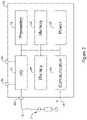
- FIG. 2illustrates a block diagram of an implantable medical device
- the illustrationindicates various functional blocks within a device 50, including a processing block 52, memory 54, power supply 56, input/output circuitry 58, therapy circuitry 60, and communication circuitry 62. These functional blocks make up the operational circuitry of the device.
- the I/O circuitry 58can be coupled to one or more electrodes 64, 66 on the device 50 housing, and may also couple to a header 68 for attachment to one or more leads 70 having additional electrodes 72.
- the communication circuitry 62may be coupled to an antenna 74 for radio communication (such as Medradio, ISM, or other RF), or alternatively to a coil for inductive communication, and/or may couple via the I/O circuitry 58 to a combination of electrodes 64, 66, 72, for conducted communication.
- radio communicationsuch as Medradio, ISM, or other RF
- I/O circuitry 58may couple via the I/O circuitry 58 to a combination of electrodes 64, 66, 72, for conducted communication.
- the processing block 52will generally control operations in the device 50 and may include a microprocessor or microcontroller and/or other circuitry and logic suitable to its purpose. Processing block 52 may include dedicated circuits or logic for device functions such as converting analog signals to digital data, processing digital signals, detecting events in a biological signal, etc.
- the memory blockmay include RAM, ROM, flash and/or other memory circuits for storing device parameters, programming code, and data related to the use, status, and history of the device 50.
- the power supply 56typically includes one to several batteries, which may or may not be rechargeable depending on the device 50. For rechargeable systems there would additionally be charging circuitry for the battery (not shown).
- the I/O circuitry 58may include various switches or multiplexors for selecting inputs and outputs for use. I/O circuitry 58 may also include filtering circuitry and amplifiers for pre-processing input signals. In some applications the I/O circuitry will include an H-Bridge to facilitate high power outputs, though other circuit designs may also be used.
- Therapy block 60may include capacitors and charging circuits, modulators, and frequency generators for providing electrical outputs. An implantable monitoring apparatus may omit the therapy block 60 and may have a simplified I/O circuitry used simply to capture electrical or other signals such as chemical or motion signals.
- Communications circuitry 62may include a frequency generator/oscillator and mixer for creating output signals to transmit via the antenna 74.
- Some devices 50may include a separate or even off-the shelf ASIC for the communications circuitry 62, for example.
- an inductive coilmay be included.
- Devicesmay also use optical or acoustic communication approaches, and suitable circuits, transducers, generators and receivers may be included for these modes of communication as well or instead of those discussed above.
- some devices 50may include a Reed switch, Hall Effect device, or other magnetically reactive element to facilitate magnet wakeup, reset, or therapy inhibition of the device by a user, or to enable an MRI protection mode.
- a device lacking a leadmay have plural electrodes on the housing thereof, as indicated at 64, 66, but may omit the header 64 for coupling to lead 70.
- a leadless devicemay use a header to couple to an electrode support feature that is attached to or wraps around the device housing.
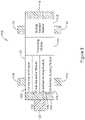
- FIG. 3shows an illustrative LCP design.
- the LCP 100is shown as including several functional blocks including a communications module 102, a pulse generator module 104, an electrical sensing module 106, and a mechanical sensing module 108.
- a processing module 110may receive data from and generate commands for outputs by the other modules 102, 104, 106, 108.
- An energy storage moduleis highlighted at 112 and may take the form of a rechargeable or nonrechargeable battery, or a supercapacitor, or any other suitable element.
- the deviceis shown with a first end electrode at 114 and a second end electrode at 116.
- a number of tines 118may extend from the device in several directions. The tines 118 maybe used to secure the device in place within a heart chamber.
- Another attachment structureis shown at 120 and may take the form of a helical screw, if desired. In some examples, tines 118 are used as the only attachment features.
- Tissue attachment and retrieval featuresmay be included in the LCP including those features shown in US PG Patent Publications 20150051610 , titled LEADLESS CARDIAC PACEMAKER AND RETRIEVAL DEVICE, and 20150025612 , titled SYSTEM AND METHODS FOR CHRONIC FIXATION OF MEDICAL DEVICES. Fixation and retrieval structures may instead resemble that of the Micra TM (Medtronic) or Nanostim TM (St. Jude Medical) leadless pacemakers.
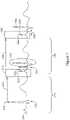
- Figure 4shows an illustrative cardiac signal.
- a far field representationthat is, a signal captured using only electrodes that are neither in nor on the heart
- the trace 150is marked using standard convention with the P-wave, R-wave (which, when combined with preceding Q-wave and following S-wave may be referred to as the QRS complex), and later T-wave.
- the P-waverepresents atrial depolarization associated with atrial contraction to load the ventricles
- the R-wave or QRS complexrepresents ventricular depolarization associated with the ventricles contracting to pump blood to the body and lungs
- the T-waveis associated with the electrical activity that repolarizes the ventricular muscle in preparation for a next beat.
- the timing of these individual eventsmay be anomalous or abnormal, and the shape of depolarization waves can be different from that show as by, for example, having a much wider QRS complex or R-wave.
- the intracardiac electrodesare placed to detect the atrial depolarization while also delivering resynchronizing pacing therapy to one or both ventricles.
- the circuitry of a single devicewould receive, directly, information for the P-wave allowing delivery at a timed interval of a pacing pulse to resynchronize contractions and improve pumping efficiency.
- the LCPmay be unable to identify the P-wave generated in the atria from an implanted location in the ventricle. Therefore the LCP, in several embodiments of the present invention, relies on a second medical device such as a subcutaneous cardiac monitor or SICD to determine whether and when the P-wave occurs.
- a second medical devicesuch as a subcutaneous cardiac monitor or SICD
- the SICD(or subcutaneous cardiac monitor) may be optimized for detection of R-waves and/or QRS complexes, in order to ensure that deadly arrhythmias (ventricular fibrillation and/or polymorphic ventricular tachycardia) can be appropriately and quickly identified.
- P-wavesmay be detected using separate parameters and/or analysis from R-wave detection for such a device.
- a time window for P-wave detectionis defined during which the SICD may specifically look for the P-wave.
- Such windowsmay be defined by analysis of the cardiac signals obtained from a patient using, for example, a ventricular event such as the R-wave / QRS complex or the T-wave as the starting point for timing delays 152, 154 shown in Figure 4 .
- Durations 152, 154may be dynamic to adjust to the overall beat rate of the patient using data gathered from a patient or using a formula or accepted relationship.
- Another optimizationmay include having the SICD (or subcutaneous cardiac monitor) use a dedicated sensing configuration to separately detect ventricular events and a second, separately defined dedicated sensing configuration to separately detect atrial events.
- the Emblem TM S-ICD systemperforms vector selection to identify a sensing vector having optimal R-wave amplitude and signal to noise ratio as a default vector for sensing the patient's cardiac rhythm, as disclosed for example in US Patents 7,783,340 , titled SYSTEMS AND METHODS FOR SENSING VECTOR SELECTION IN AN IMPLANTABLE MEDICAL DEVICE USING A POLYNOMIAL APPROACH, and 8,483,843 SENSING VECTOR SELECTION IN A CARDIAC STIMULUS DEVICE WITH POSTURAL ASSESSMENT.
- a second vector selection and/or sensing configuration processmay be used to determine how the P-wave will be detected by a given device.
- filtering, gain, or other characteristicsmay be selected specific to P-wave detection.
- a P-wave sensing channel passbandmay be set to a different passband.
- the R-wave or ventricular event passbandmay be set in the range of 3-40 Hz, or 9-40 Hz, or other setting.
- the P-wave passbandmay be set to a different range, for example, 0.5 to 20 Hz.
- band setting and selectionmay be partly contingent on reviewing the captured signal of either or both of ventricular and/or atrial events.
- a sensing channel passbandmay be used to select a sensing channel passband(s).
- a passbandmay be varied until signal amplitude for the desired atrial or ventricular feature begins to drop, at which an edge or comer of the passband may be set, to achieve a targeted, narrow passband.
- a P-wave sensing or atrial sensing configurationmay use a different frequency band than a corresponding R-wave sensing or ventricular event filter.
- a single passbandmay be set for use in each of atrial and ventricular sensing, or different pre-set ranges may be used for each of atrial and ventricular sensing
- Setting the sensing configuration for detecting P-wavesmay thus include either or both of setting a detection window and/or selecting a filter configuration.
- the actual manner of detecting the P-waveis defined in some illustrative examples as part of the sensing configuration.
- the P-wavemay be detected by comparing a detected signal to a fixed or time-varying amplitude threshold.
- the P-wavemay be detected by comparing segments of captured signal to a template until a match is found or at timeout occurs. When a match is found a P-wave detection can be declared; if a timeout occurs, it may be concluded that the P-wave was not present or simply not seen.
- more than one method of identifying P-wavesmay be available for use, and a most effective approach for a given patient may be selected. For example, if amplitude threshold and template match approaches to P-wave detection are available, a patient having highly variable amplitude signals may have his or her device configured to use the template match approach rather than an amplitude based approach.
- a possible P-waveis confirmed as such prior to generating an output communication.
- a template of the P-wavemay be defined and used to confirm whether a detected signal that crosses an amplitude threshold is in fact a P-wave by comparing the detected signal to the template.
- Such templatesmay be static and stored in memory, may be matched from one beat to the next by comparing a first in time P-wave to a next in time possible P-wave, or may be a hybrid of a stored template and fully dynamic template as by, for example, averaging in newly detected P-waves to a template.
- patientsmay be pre-screened for P-wave availability with the second medical device that is to be used for synchronizing LCP pacing. For example, it may well be that due to anatomical variations or other factors, some patients will have a well-defined P-wave providing a ready fiducial for the SICD or subcutaneous cardiac monitor to rely upon to prompt CRT therapy by an LCP. In other patients, the P-wave may be difficult to detect consistently. Thus a prescreening process may be performed, either as an in-clinic test, or by having a patient use a Holter monitor or by implanting a subcutaneous cardiac monitor to ensure that the P-wave is readily identified consistently.
- FIG. 5Ashows another illustrative cardiac signal, this time with indications of a pacing therapy being delivered.
- the traceis shown at 170 with an intrinsic non-paced R-wave shown at 172.
- This R-wave at 172is a fiducial for a time period 174 that defines a P-wave detection window at 176.
- a maximum positive slope point associated with the T-wave, indicated at 180may serve as the fiducial for a duration 182 that again defines the P-wave detection window 176.
- these interactionsmay be described by stating that a ventricular event is used to generate the fiducial for a window detection of the atrial event.
- FIG. 5Bshows example timing fiducials for a signal.
- a signal 200may cross an amplitude threshold, creating a fiducial at 202 when going up, or another fiducial at 204 when coming back down.
- An amplitude peak 206may instead be used.
- an inflection 208may be used, with either positive slope or negative slope inflections available.
- a fiducial 210may rely on the area under the curve crossing a defined threshold. Any of these, or other, fiducials may be used to establish a point in time from which counting begins for purposes of defining a P-wave detection window. Fiducials may be applied to a prior P-wave, to a QRS complex, to an R-wave, or to the T-wave. The ST segment may be used if desired as by, for example, calculating a mid-point or other feature thereof.
- a P-waveis detected and, in some examples, confirmed within the P-wave detection window 176, another fiducial is set at 190 and, following a P-wave to pace delay 192, a pacing therapy is delivered as shown at 194.
- the delay 192may be calculated by either the LCP that delivers the pace therapy or by the second device that provides a command to deliver therapy or other information indicating the occurrence of the P-wave.
- Such delay 192may encompass and/or accommodate system latency (delays due to the time required to analyze data, make a decision, communicate data, receive communicated data, analyze the received data to determine the purpose of the communication, and generate therapy output).
- the pacing therapy 194is shown as a monophasic, rectangular pulse, however, this is merely for illustration.
- the pacing pulsemay be monophasic or biphasic, with the latter being more common than the former.
- Typical pace deliverycan be either constant current or constant voltage, however, more complex waveforms such as ramped, exponential, and/or triphasic waveforms, or any other suitable waveform, may be used.
- the pacing therapy 192stimulates enough of the myocardium, either directly or by augmenting existing neural signals, to capture the heart.
- a QRS complexoccurs causing beat 196.
- a brief visual comparison of QRS complex of beat 196 to the non-paced complex for beat 178shows that, as is typical, the paced beat at 196 has a different shape or morphology than the intrinsic beat 178, with a more exaggerated Q-wave, and a differently shaped S-T segment.
- Other differencesmay be noted as is understood in the art. Such differences (or others) may be used, if desired, to aid in having a second device analyze the efficacy of CRT therapy delivered by an LCP.
- Detection in the P-wave detection windowmay take several forms.
- the obtained cardiac signalmay be compared to a P-wave detection threshold, which may be, for example, based on prior P-waves that have been detected.
- the obtained signalmay be analyzed to determine whether a peak slope, combined with an amplitude, occurs. For example, the obtained signal may be analyzed for an upward slope of a select shape lasting for a minimum duration or minimum change in amplitude.
- a signal 220comprises a first QRS complex at 222.
- a detection profile for R-wave detectionis shown at 224 and may be a time-varying detection profile having a refractory period to pass over the QRS complex, followed by a constant threshold period to pass over the T-wave, followed by a decay period.
- a new ventricular event detectionis declared, in this case associated R-wave 226.
- the height of various parts of detection profile 224may be calculated by reference to one or more previously detected R-waves as discussed in US Patent 8,565,878 , for example.
- P-wave detectiontakes place in the P-wave detection window at 230.
- the P-wave 232is detected when signal 220 crosses P-wave detection threshold 234.
- the P-wave detection threshold 234may be set by reference to the amplitude of one or more previously detected P-waves.
- the P-wave detection threshold 234may be scaled relative to the detection profile 224 (such as a 20% to 80%, or more or less of detection profile 224). The P-wave detection may then be used to trigger a pacing pulse (not shown) as described elsewhere in the present document.
- Figure 5Dshows another example.
- a cardiac signalis shown at 240 with a P-wave detection window at 242.
- the signal in window 242is expanded as shown at 242'.
- a P-wave templateis shown at 244.
- To detect the P-wavea series of comparisons are made as incoming signal is received. Once enough signal is received to perform a morphology comparison, such as by difference of area, correlation waveform analysis, wavelet transform, or principal components analysis, for example, a morphology comparison is made.
- the morphology comparisonis repeated as more signal comes in, with data entering a comparison window on a first-in, first-out basis, until a match is found at 248. Match 248 is then the P-wave detection.
- a P-wave detection window 242may be searched to identify a specific feature associated with a possible P-wave. For example, a P-wave may be identified by observing whether a slope in excess of a threshold and with a minimum pathlength occurs during the P-detection window. Additional ways to confirm that a signal is a P-wave are discussed relative to Figure 6 .
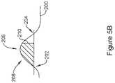
- Figure 6illustrates additional ways that a signal feature such as a P-wave may be analyzed for confirmation purposes.
- a P-wave detection windowis defined as shown at 260.
- the signal within the window 260includes a peak.
- to confirm that the signal within the window 260 is actually a P-waveit may be analyzed for having at least a minimum amplitude 264.
- slope characteristicssuch as a combination of rise and run may be analyzed, as shown at 266, where the rise is the amount of change of amplitude, and run is the duration within which the amplitude change occurs.
- matchingusing for example a difference of area analysis, correlation waveform analysis, wavelet transform, or principal component analysis, may be used to compare the shape of peak 262 to another signal such as the shape of the signal in a prior P-wave detection window, shown at 250, using the signal shape therein 254 across all or a portion of the window 250.
- a beat-to-beat comparisonmay be termed a dynamic comparison, as the shape against which the newly detected possible P-wave is compared will change with each new cardiac cycle.
- a stored templatesuch as shown at 280, may be used. In this example, shape 262 would be compared against the shape 282 defined by the template 280. If a stored template does not change with time, it may be deemed a static template.
- a hybrid templatemay be configured to change slowly with time by averaging an existing data set with a newly detected and confirmed P-wave, or by averaging several preceding P-wave detections.
- FIG. 7shows another cardiac signal to illustrate operation of an embodiment.
- the cardiac signalis shown at 300.
- a first cardiac cycleis shown at 310 including an intrinsic P-wave, non-paced QRS complex, and trailing T-wave.
- the R-wave peakis used as a fiducial at 312 to start a timer that expires with duration 314, triggering the start of a P-wave detection window 316.
- the SICD or subcutaneous cardiac monitorsearches for a P-wave.
- the operation during the detection window 316may include selecting a specific sensing configuration (sensing vector, filtering or the like) to observe for an atrial event such as the P-wave.
- an atrial senseoccurs at 320, corresponding in this example to the peak amplitude of the P-wave.
- a delayis instituted at 322 prior to delivery of a ventricular pacing stimulus at 324.
- the delay 322is a calculated delay, which may include a lag period to allow for analysis by the SICD or subcutaneous cardiac monitor, transmission of data or a command to an LCP, processing by the LCP, plus, if desired, some intentional delay to allow for appropriate timing of the pace pulse 324 to optimize pacing efficiency.
- an AV delay controlmay be used to institute appropriate delay from a P-wave or atrial event sense to the delivery of ventricular pacing therapy.
- the AV delaycan include both system lag as well as intentional delay.
- a devicemay include special handling instructions for communication to the LCP during period 322, to count how many retries occur in the event that a communication message is not received or acknowledged appropriately. Thus, if for some reason (such as external interference), the initial communication from the SICD or subcutaneous cardiac monitor the LCP is not received, subsequent tries may indicate how many retries have occurred to allow the LCP to appropriately manage period 322. If there are multiple retries, the pacing pulse 324 may be inhibited, if desired, to avoid extending period 322 beyond a set limit. Rather than relying on a quantity of retries, the LCP may simply timeout.
- the P-wave at 320is the start of a new cardiac cycle 330, which in this case now includes a paced QRS complex at 332 having a distinct morphology relative to the first complex 310.
- the devicemay alter its selection of fiducials to define a next P-wave detection window, shown at 342.
- the delay 340is now instituted from the pace delivery at 324, rather than the R-wave.
- the next atrial event or P-wave detection windowis shown at 342.
- a pacing therapy pulseis delivered at 348 again causing a pace-captured QRS complex shown at 350.
- the delay at 346may be the same as, or different from, the delay at 322, if desired.
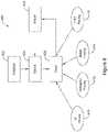
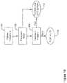
- FIGS 8 , 9 , and 10A-10Bshow block diagrams for illustrative examples.
- the overall method of using an implantable medical deviceis shown at 400.
- the device or systemis initialized at 402, following which treatable conditions are detected at 404 and treatment is delivered at 406.
- treatment 406may include delivering a therapy shock for ventricular fibrillation or polymorphic tachyarrhythmia, as indicated at 410.
- an SICDmay deliver a defibrillation shock at 410.
- antitachycardia pacing (ATP)may be delivered as shown at 412.
- an LCPmay deliver ATP in response to a request or command by an SICD, or of its own accord.
- An SICDmay also deliver ATP if desired.
- Bradycardia pacingmay be delivered by one or the other of an LCP or SICD, with the LCP likely being preferred due to the possible discomfort that SICD pacing delivery can cause the patient.
- the Bradycardia pacingmay be delivered to treat AV block using a right ventricular LCP.
- CRT pacingmay be delivered at 416.
- Adjustments to the system configuration and other settingsmay be performed as indicated at 420, for example, in response to the various therapies 410, 412, 414, 416.
- CRT pacing 416is delivered but fails to generate fusion beats
- an adjustmentmay be made to the timing between P-wave detection and pacing delivery, or to the duration, amplitude, or other characteristics of the delivered pacing therapy.
- bradycardia pacing 414is delivered but fails stimulate a ventricular contraction, the delivered therapy may be adjusted 420 by using a different amplitude, pulse width, or shape.
- sensing configuration(sense vectors and filtering, for example, for one or both of ventricular and/or atrial event detection) may be established during initialization to optimize sensing of ventricular and/or atrial events.
- Communication operationsmay be initialized as well, for example as discussed in US Patent Application Nos. 15/070,013 , titled COMMUNICATIONS IN A MEDICAL DEVICE SYSTEM WITH LINK QUALITY ASSESSMENT, and/or 15/058,412 , titled COMMUNICATIONS IN A MEDICAL DEVICE SYSTEM WITH TEMPORAL OPTIMIZATION.
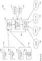
- FIG 9shows a more detailed discussion of initialization relative to sensing parameters.
- initializing datais obtained as indicated at 452, and one or more sensing vectors are selected, as indicated at 470.
- the detection parameterssuch as parameters for detecting P-waves or atrial events (P-Detect Parameters) are set, as indicated at 480.
- steps 452, 470 and 480focus on the operations of the SICD or subcutaneous cardiac monitor for a system such as shown in Figure 1 having both a subcutaneously located device along with an LCP.
- the LCPmay also be setup for sensing configuration to optimize its ability to detect signals originating in whatever chamber of the heart the LCP is located in, and/or to filter out noise signals.
- the step of obtaining initializing data at 452may include various subprocesses as indicated on the left side of Figure 9 .
- a plurality of individual cardiac cyclesmay be detected at 456 in one or several sensing vectors or with one or several different sensing configurations (affecting for example, filtering and/or amplification parameters, possibly in combination with vector selection parameters).
- the individual detections of cardiac cyclesmay be analyzed 458 by, for example, binning different detected data elements from each cycle as discussed in US Patent 7,783,340 , titled SYSTEMS AND METHODS FOR SENSING VECTOR SELECTION IN AN IMPLANTABLE MEDICAL DEVICE USING A POLYNOMIAL APPROACH.
- a set of cardiac cyclesare detected as indicated at 462 and a composite signal is generated as shown at 464.
- a composite signalis generated as shown at 464.
- the use of a composite signal to establish sensing vector quality metricsis discussed, for example, in US PG Patent Pub. No. 2017/0113053 , titled SIGNAL QUALITY MONITORING FOR MULTIPLE SENSE VECTORS IN CARDIAC DEVICES.
- sense vector configurations for ventriculartargeting, for example, R waves, the QRS complex, and/or T-waves
- atrial event detectiontargeting, for example, the P-wave
- the vector configurationmay include selecting combinations of electrodes to use, combinations of two or more vectors to use together, and/or the setting of filtering, blanking, refractory, amplification or other parameters.
- Various approaches to vector selectionmay be used including those referenced above from other patents or patent applications, as well as those discussed herein. For example, consistency of a vector configuration may be used, as indicated at 472, to select a given vector.
- Consistency 472may mean, for example, that a selected cardiac event (P, R or T waves, or the QRS complex) is consistent in shape, amplitude and/or timing, in a given vector configuration.
- strength 474 of the signal, absolute and/or relative to noisemay be considered as well.
- the parameters for identifying P-wavesare set as indicated at 480.
- the sensing configuration stepmay be bypassed, and P-Detect parameters set at 480.
- block 470may be performed in some embodiments only when connected to a clinician programmer to ensure that appropriate signals are obtained and/or that sensing configuration is not modified contrary to known patient history, while blocks 452 and 480 may be performed by a device independent of programmer intervention.
- block 480may be omitted, with the sensing vector setup performed and any suitable method of P-wave detection used by the device without necessarily performing a separate optimization at 480.
- Block 480calls for setting one or more parameters to optimize P-wave detection. In some examples, this may include selecting one or more of the fiducials from which P-wave detection is triggered, at 482, setting a window for detecting the P-wave 484, selecting the features to look for when attempting to detect a P-wave 486, or selecting a template for P-wave confirmation at 488. Any of blocks 482, 484, 486, 488 may be used in various combinations or, in some examples, standing alone.
- the fiducial selection at 482may be used to select a feature (whether atrial or ventricular, such as an R-wave, a T-wave, a preceding P-wave, or other physiological, such as a heart sound, a blood pressure signal, or other timing point of reference such as delivery of a pacing pulse), that starts a blanking period during which P-waves cannot be detected, for example, to pass over the T-wave, and upon expiration of the blanking period, P-wave detection is enabled.
- the fiducial 482may be used to trigger the initiation of an analysis window for the P-wave.
- the window 484may be used as shown above in Figures 5A , 6 and 7 by, for example, determining relative to a selected fiducial point when the P-wave typically appears and then setting a window of a duration equal or longer than the P-wave for allowing P-wave detection.
- the windowmay be, for example, about 50 to 400 milliseconds. In another example, the window may be about 100 to about 200 milliseconds. Other durations may be used.
- a P-wavemay be identified by having an amplitude of a certain range, such as greater than a threshold.
- a thresholdmay be adaptive to current patient conditions by, for example, setting it to some percentage (50% to 90%, or more or less) of a preceding P-wave or an average of several preceding P-waves, or stored information relating to typical P-waves generally or specific to a given patient.
- Other featuresmay include a maximum or minimum slope amplitude or length.
- the P-wavemay be identified by the detected signal moving in a certain direction within predefined slope parameters for at least a predetermined amplitude or period of time.
- the signalmay have an upward slope that is characteristic of the P-wave, not so steep as for the R-wave, but steeper than the T-wave, of at least a select duration to avoid noise detection.
- Slope analysismay take place by using the first or second derivative of the obtained signal.
- Other featuresmay be used instead at block 486.
- the template 488may also be used independent of other items to detect a P-wave.
- the templatemay be compared to received data on a continuous or semi-continuous basis, and when a match is found, a P-wave may be declared (see Figure 5d , above).
- the templatemay be an averaged composite of prior signals, or may be simply a prior P-wave, or may be constructed in any other suitable manner.
- the incoming signalitself may be a signal averaged composite of several cardiac cycles having, for example, P, Q, R and S signals (and T-waves if the composite is so configured).
- a templatemay be compared to an incoming data stream to identify a match.
- the template 488may be used to confirm a detected likely P-wave, such as a signal that crosses a defined amplitude threshold during a P-wave detection window. If the template 488 matches the likely P-wave, then P-wave detection is confirmed or, alternatively, if there is no match to the template 488, then the detection may be discarded as not being a P-wave.
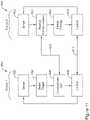
- Figures 10A-10Bshow summary characterization of two approaches to sensing configuration.
- datais captured at 500.
- VT/VF sensing 502 configuration and parametersare set by, for example, setting up sensing vectors and filtering, storing morphology information (templates, wavelet transforms or the like known in the art) for differentiating normal from abnormal cardiac activity, and the like.
- sensing configuration to be used for bradycardia therapy and/or CRT therapy controlis set at 504.
- Block 504may include configuring sensing vectors or combinations, filtering, and the like, as well as template selection, window setting and fiducial assessment, or other steps noted both above and below.
- FIG. 10Bshows another characterization.
- datais obtained at 510, following by setting ventricular sensing parameters at 512.
- Ventricular sensing 512 parametersmay be optimized to detect R-waves and/or VT/VF signals, including filtering and vector selection or combinations, as well as threshold setting and/or template formation.
- Atrial sensing parametersare set at 514, and may include optimization to detect P-waves or other atrial events including filtering, windowing and vector selection or combinations, as well as threshold setting and/or template formation.
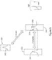
- Figure 11shows in block flow form operation of two cooperating devices.
- a first deviceperforms operations as shown at 600, while a second device performs operations as shown at 620.
- Communications between the deviceare shown at 610, 612, though it should be understood that additional back and forth communication may also take place during device operations.
- each deviceis sensing for cardiac activity, as shown at 602, 622.
- Device 1which may be an SICD or subcutaneous cardiac monitoring device
- Device 2may or may not perform sensing.
- Device 2may omit sensing and may instead simply rely upon Device 1 for therapy directions.
- both devicessense for cardiac (or other) activity.
- Device 2may observe whether a ventricular extra-systole event such as a premature ventricular contraction (PVC) occurs, or whether the ventricles otherwise "beat" before an atrial event is detected. (see Figure 18 , below for such exception handling).
- PVCpremature ventricular contraction
- Device 1detects a trigger.
- the triggermay be, for example, an atrial event such as a P-wave.
- the P-wavemay be detected during a P-wave detection window, or may be detected by comparing a received signal to a template. If desired, the P-wave may be both detected and confirmed by using a detection method (comparing to an amplitude during a P-wave window, for example) and a confirmation method (comparing a possible P-wave signal to a template).
- Device 1then communicates out, as shown at 606, issuing a communication to Device 2, which is then received at Device 2.
- the communicationmay command or request a therapy delivery, or may indicate that a P-wave has been detected.
- Device 2may receive a command for pacing therapy and simply respond by generating a pacing output.
- Device 2may receive a request for therapy delivery and proceed to deliver the requested therapy unless an exception arises before or after the request is received.
- Device 2may receive an indication that a P-wave has been observed by Device 1, and Device 2 may then determine whether pacing or other therapy is appropriate.
- Device 2After receiving the communication at 624, in the example shown, Device 2 delivers therapy at 626. Either or both of the two devices may, optionally, confirm that therapy was effective at 608 and 628. This confirmation may be communicated between the devices, as indicated at 612. For example, Device 1 may confirm that therapy was effective by observing the morphology of the cardiac signal following therapy delivery using, for example, a paced beat template. Device 2 may confirm that therapy was effective by observing morphology or by any other suitable manner. Alternatively, communication 612 may be omitted. For example, Device 1 may restart its sensing cycle following detection of an evoked response to therapy 626, or after detecting therapy 626; Device 2 may restart its sensing cycle following delivery of therapy 626.
- a third devicemay be an LCP that functions similar to Device 2.
- a first LCPmay have a right ventricular location and a second LCP may have a left ventricular location, allowing biventricular pacing to be delivered, with both LCP devices generating therapy output relying for timing information upon Device 1's detection of an atrial event.
- each LCP devicemay be separately programmed to delay therapy 626 from the trigger detected at 604 to achieve desirable resynchronization characteristics.
- Such timingeither with a single or plural LCP devices involved, may be addressed in part using methods illustrated by Figures 12A-12B .
- FIGS 12A-12Billustrate different manners of handling cross-device timing.
- the operation of an LCPis illustrated in which the LCP receives a communication at 650.
- the communicationincludes a timestamp associated with the time at which a therapy trigger was identified by the SICD, which timestamp is extracted from the communication in block 652.
- the timestampmay be a relative timestamp as indicated at 654.
- a relative timestampmay be based on a system event such as the point in time of a prior communication, or of a prior therapy delivery as detected by the SICD.
- the SICDmay be capable of determining when a pacing pulse is delivered by the LCP, and may communicate the timing of a detected trigger relative to the LCP prior pacing pulse; in this way, the LCP need not synchronize its clock to the SICD and instead simply tracks when it last delivered a therapy.
- the timestampmay be based on a synchronization clock signal as indicated at 656, where one of the devices (LCP or SICD) includes a system clock to which each device is synchronized. Using the timestamp, the LCP determines when, relative to the trigger event, therapy should be delivered as indicated at 660.
- Figure 12Bshows a somewhat simpler approach.
- a communicationis received at 680, and therapy is delivered based at 682, without relying on a timestamp of the communication.
- the LCPdetermines when it received the communication and determines when to deliver therapy based on the communication time.
- the method of Figure 12Brelies, in part, on an assumption that the time from a trigger event to communication is predictable and repeatable.
- communication retriescan occur when a communication is issued but not acknowledged by the intended recipient. Retries would therefore potentially delay therapy in the method of Figure 12B .
- the communication provided from the SICDmay indicate whether it is the first communication in response to a given trigger, or whether it is a retry, such that the LCP can adjust its timing according to whether there have been one or more communication retries.
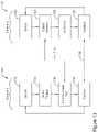
- Figures 13-18show in block flow format operations of two cooperating devices. As noted for Figure 11 , there may be more than just the two devices represented in these drawings, with additional LCP devices operating similar, in some examples, to "Device 2" of the Figures.
- FIG 13illustrates operations for Device 1 (which may be an SICD or a subcutaneous cardiac monitor) at 700 and Device 2 (which may be an LCP) at 720.
- each of the devicessense obtained signals looking to detect one or more predefined events.
- Device 1detects a trigger event, such as an atrial event or P-wave, as indicated at 704.
- Device 2also detects an inhibiting event as indicated at 724.
- An inhibiting eventmay be, for example, a QRS complex or an R-wave, or a PVC.
- Such detection at 724may occur by, for example, comparing received signals against a threshold defined at a high enough amplitude to pass over typical P-waves and/or T-waves.
- Device 2may respond to the communication at 710 by ignoring it, or by providing a response to Device 1 to indicate that no therapy will be delivered due to the inhibitor having been detected.
- the two devicesmay, as before, confirm status at 708, 728, with or without communication 712 therebetween.
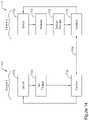
- Figure 14shows another example with operations for Device 1, which may be an SICD or a subcutaneous cardiac monitor, shown at 750, and for Device 2, which may be an LCP, at 770.
- Device 1applies its sensing for a trigger at 752, however, no trigger is detected at 754.
- Device 2also senses at 772, but encounters a timeout without detecting an inhibiting event and without receiving a communication from Device 1 indicating that therapy should be delivered. Such a scenario may, in some examples, inhibit therapy entirely.
- Device 2delivers therapy at 776 in response to a timeout at 774.
- the timeout 774may occur if a relevant escape interval expires for a patient who is both pace dependent and receiving CRT, for example.
- the devicesmay confirm status at 756, 778 with or without communication therebetween at 760.
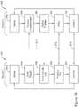
- Figure 15shows another example with operations for Device 1, which may be an SICD or a subcutaneous cardiac monitor, shown at 800, and for Device 2, which may be an LCP, at 820.
- Device 1 and Device 2apply sensing parameters at 802, 822, respectively.
- Device 1detects a trigger at 804 and communicates out to Device 2 at 806, commanding or requesting therapy, or simply indicating presence of the trigger 804.
- Device 2receives communication 810 at 824, and then delivers therapy 826 in response to (and after a determined delay relative to) the trigger. In this example, however, Device 1 continues sensing after the Communication out at 806, and determines that therapy failed to capture the heart.
- Such failuremay be determined by either the absence of an R-wave or QRS complex in response to the therapy 825, or by analyzing the R-wave or QRS complex that does occur and determining it does resemble a captured beat (by for example determining a capture template is not matched), or that it occurred at a time indicating no capture (that is, the responsive contraction may occur too late or too early to have been a response to the stimulus).
- the therapy failure 808is then communicated to Device 2, which modifies therapy at 828.
- Therapy modification 828may include, for example, changing therapy amplitude, pulse width or other shape/energy characteristic, changing the timing of therapy by increasing or reducing a delay from the trigger, changing a therapy polarity, polarity type, or electrode configuration, or by changing other suitable therapy characteristic(s).
- the specific therapy modification 828may be determined by either of Device 1 or Device 2.
- Device 2in this example, may store new pacing parameters for use in a next iteration.
- Figure 16shows an alternative to Figure 15 .
- Each of Device 1 and Device 2apply sensing parameters at 852, 882, respectively.
- Device 1detects a trigger at 854 and communicates out to Device 2 at 856, commanding or requesting therapy, or simply indicating presence of the trigger 854.
- Device 2receives communication 870 at 884, and then delivers therapy 886 in response to (and after a determined delay relative to) the trigger.
- Device 1continues sensing after the Communication out at 856, and determines that therapy failed to capture the heart as indicated at 858.
- a communicationis issued at 872 in response to the finding that therapy failed at 858, and therapy is retried at 888 by Device 2.
- Plural retriesmay take place, and the retry of therapy may occur with changed parameters including increasing amplitude and/or pulse width, changing polarity, polarity type or electrode configuration, or by changing other suitable therapy characteristic(s).
- the devicesconfirm that the heart beat took place at 860, 890, with or without communication therebetween 874.
- Device 2in this example, may store new pacing parameters for use in a next iteration.
- the scenario of Figure 16is less likely to be needed in many CRT patients; instead, those who are pacemaker dependent, for example having an AV block, may benefit by use with right ventricular placed LCP (see item 40, Figure 1 ).
- Figure 17shows another illustrative example.
- Operations for Device 1, which may be an SICD or a subcutaneous cardiac monitor,are shown at 900.
- Operations for Device 2, which may be an LCP,are shown at 920.
- Each of Device 1 and Device 2apply sensing parameters at 902, 922, respectively.
- Device 1detects an inhibitor at 904 which may be, for example, a QRS complex, an R-wave, or a PVC.
- Device 1may detect an inhibitor 904 as a premature atrial contraction (PAC).
- PACpremature atrial contraction
- Device 1may generate a communication 910 to Device 2.
- Device 2receives the communication at 924, and inhibits therapy as indicated at 926.
- the two devicesmay confirm status at 908, 928, with or without communication 912 therebetween.
- the scenario of Figure 17may arise, for example, if Device 2 is configured to deliver therapy at a given interval absent an inhibition command.
- parameters for sensingmay be modified to use different periods and fiducials for the starting point of timeouts. Referring briefly to Figure 7 , for example, the following may change depending on whether an intrinsic beat (shown at 302) or paced beat (shown at 332) occurs:
- Figure 18shows a pre-implantation process flow.
- a patient having appropriate indications for CRTis first identified as indicated at 950.
- Such indicationsare well known in the art any may include, for example, a wide QRS complex, left bundle branch block, the New York Heart Association Functional Classifications, as well as information about comorbidities.
- the patientmay undergo prescreening for adequacy of cardiac signals as captured by the SICD, as indicated at 952.
- Step 952may, for example, use tools, metrics and methods discussed in US Patent 8,079,959 , titled PATIENT SCREENING TOOLS FOR IMPLANTABLE CARDIAC STIMULUS SYSTEMS, and/or US Patent Application Ser. No.
- the size and/or consistency of the R-wave and/or the signal to noise ratio of the cardiac signalmay be observed, or the ability of an implantable device algorithm to correctly analyze obtained cardiac signals may be determined prior to implantation by applying an algorithm that the device would use once implanted to signals obtained before implantation. A similar process may then be repeated with respect to the P-wave, as indicated at 954. If both prescreens pass, then the patient may receive a combination of SICD and LCP, as indicated at 956. If either of the prescreens 952, 954 fail, then the patient may be implanted with a transvenous CRT system as indicated at 958.
- the patientmay pass the SICD screening and could then receive a CRT-P device transvenously, paired with the SICD.
- the CRT-P device and SICDmay communicate with one another as desired including in some examples the above methods for using the SICD to assist in determining whether and when the CRT-P would provide pacing therapy in one or more chambers of the heart.
- a first illustrative examplemay take the form of an implantable device system comprising a first medical device (14, 40) comprising pacing means for delivering a pacing therapy to the heart of a patient, and a second medical device (16) comprising sensing means to sense activity of the heart of the patient.
- the pacing meansmay comprise a controlling output digital to analog converter (using either voltage or current control) configured to deliver an output current or voltage via output circuitry of an implantable device, such as illustrated with the pulse generator module 104 in Figure 3 , for coupling to one or several of the electrodes 114, 116, and/or 118.
- the sensing meansmay comprise processing circuitry including, for example, filtering, amplifying and, as needed, analog-to-digital converting circuitry 52, coupled via input/output circuitry 58 to one or several electrodes such as electrodes on a canister/housing shown at 64, 66 and/or at 72 on lead 70, all of which are shown in Figure 2 .
- the first medical devicealso comprises first communications means for at least receiving communications from at least the second medical device, and the second medical device comprises second communications means for at least issuing communications to at least the first medical device.
- the first communications meansmay include amplifying, modulating, demodulating, and/or processing circuitry making up a communications module 102 that may use an antenna and/or electrodes 114, 116 and/or 118 for either radiative or conducted communications, all shown in Figure 3 .
- the second communications meansmay include amplifying, modulating, demodulating and/or processing circuitry making up communications block 62, that may in turn use one or more of an antenna 74 and/or electrodes 64, 66 and/or 72 for communication, all shown in Figure 2 .
- the second medical devicecomprises atrial event means for using the sensing means to detect an atrial event in the heart of the patient and, in response thereto, to issue a communication to the first medical device.
- atrial event meansmay take the form of instruction sets stored in memory 54 for operation by a processing block 52 which may include a microcontroller, microprocessor, state machine, or other control, logic and/or processing circuitry, all shown in Figure 2 .
- the instruction sets for atrial event meansmay comprise instructions for sensing 602, detecting a trigger 604 and communicating out 606, as shown in Figure 11 , as well as analogous operational blocks of Figures 13-17 (here the second medical device in the first illustrative example may operate as "Device 1" in any of Figures 11 and 13-17 ).
- the first medical devicecomprises therapy means for using the pacing means to deliver therapy to the heart of the patient in response to the communication means receiving the communication issued by the second medical device.
- the therapy meansmay take the form of operational instructions for execution by a processing module as shown at 110, operatively coupled to a communications module 102 and the pulse generator module 104, all as shown in Figure 3 .
- the operational instructions for the therapy meansmay comprise instructions for receiving a communication 624 and delivering therapy 626 as shown in Figure 11 , as well as analogous operational blocks of Figures 13-17 (here the first medical device in the first illustrative example may operate as "Device 2" in any of Figures 11 and 13-17 ).
- a second illustrative exampletakes the form of a system as in the first illustrative example, wherein the second medical device comprises initialization means for initializing the second medical device atrial event means, including: detection means for detecting at least first and second cardiac cycles of the patient; and window means for establishing a window for detection of the atrial event; wherein the atrial event means is configured to observe cardiac signals of the patient during the window for detection of the atrial event in order to detect the atrial event.
- the initialization meansmay take the form of instruction sets stored in memory 54 for operation by a processing block 52 which may include a microcontroller, microprocessor, state machine, or other control, logic and/or processing circuitry, in which instructions the processing block 52 may control and/or access I/O block 58 to use system electrodes 64, 66 and/or 72, all shown in Figure 2 .
- Such instructions for the initialization meansmay operate to execute as shown in Figure 9 , using detection means instructions that operate as shown by one or both of 454 and 460 to obtain data as indicated at 562, and then setting parameters including, for example, a window for P-wave detection as indicated at 484.
- Figures 10A-10Bshow additional versions of the initialization means instruction sets, including obtaining data and setting brady/CRT sensing parameters 504 and/or atrial sensing parameters 514.
- Figures 5A , 5C and 5Deach show illustrative approaches to the use of such windows 176 ( Figure 5A ), 230 ( Figure 5C ), and 242 ( Figure 5D ).
- the detection meansmay be configured to calculate a composite cardiac cycle data set using the at least first and second cardiac cycles; and the window means may be configured to establish the window for detection of the atrial event using the composite cardiac cycle data set, such as illustrated at 460, 462, 464 in Figure 9 .
- the window meansis configured to set timing information for the window for detection using at least one of the following factors: a feature of a ventricular event detected by the sensing means; or occurrence of a therapy output by the first medical device;
- Figure 7illustratively shows the use of ventricular event (R-wave 312) as such a fiducial.
- these sub-examplesmay be embodied in operational instructions for operation by a processing block 52 and associated circuitry including I/O block 58 in Figure 2 .
- the initialization means of the second illustrative examplecomprises event characterizing means for determining characteristics of the atrial event, the characteristics comprising at least one of: an amplitude; a relative amplitude as compared to one or more preceding ventricular events; a relative amplitude as compared to a mean amplitude during a cardiac cycle; or a maximum or minimum slope; wherein the atrial event means is configured to use determined characteristics of the atrial event in order to detect the atrial event.
- Such features 486( Figure 9 ) may be selected and used according to operational instructions for operation by a processing block 52 ( Figure 2 ), to execute a method as illustrated in at least Figure 9 .
- the atrial event means of the first or second illustrative examplescomprises comparison means to determine whether a signal captured during the window for detection of the atrial event matches a stored atrial event template or a dynamic atrial event template and conclude whether an atrial event occurs in the window for detection using results of the comparison.
- comparison meansmay be embodied in a processing block 52 ( Figure 2 ) configured to execute instructions for performance as shown in Figure 5D .
- the second medical device of any of the first, second or third illustrative examplescomprises a plurality of electrodes configured for use in sensing cardiac signals
- the second medical devicecomprises vector selecting means comprising: ventricular signal vector means configured to analyze signals from a plurality of sensing vectors defined by the plurality of electrodes and select a first sensing configuration for detection of ventricular events; and atrial signal vector means configured to analyze signals from a plurality of sensing vectors defined by the plurality of electrodes and select a second sensing configuration for detection of atrial events.
- the vector selection meansmay take the form of instruction sets stored in memory 54 for operation by a processing block 52 which may include a microcontroller, microprocessor, state machine, or other control, logic and/or processing circuitry, controlling switches in the I/O block 58 all shown in Figure 2 , with the instruction sets configured to execute a method as shown in Figure 10B .
- a processing block 52which may include a microcontroller, microprocessor, state machine, or other control, logic and/or processing circuitry, controlling switches in the I/O block 58 all shown in Figure 2 , with the instruction sets configured to execute a method as shown in Figure 10B .
- a processing block 52which may include a microcontroller, microprocessor, state machine, or other control, logic and/or processing circuitry, controlling switches in the I/O block 58 all shown in Figure 2 , with the instruction sets configured to execute a method as shown in Figure 10B .
- Such an examplemay be designed such that the atrial event means is configured to determine one or more parameters for sensing of at
- any of the first to third illustrative examplesmay be selectively operable to treat Bradycardia, and/or to improve cardiac synchronization.
- such illustrative examplesmay be configured to allow the second medical device to indicate using the communication means that it has detected an atrial event, and wherein the therapy means is configured to determine when therapy is to be delivered relative to timing of the atrial event.
- the second medical devicehas second communication means having operational instructions configured to command delivery of therapy by the first medical device at a particular time.
- these illustrative examplesmay include a system wherein the first medical device is a leadless cardiac pacemaker, and the second medical device is an implantable cardiac monitor.
- these illustrative examplesmay include a system wherein the first medical device is a leadless cardiac pacemaker, and the second medical device is a subcutaneous implantable defibrillator.
- Method examples described hereincan be machine or computer-implemented at least in part. Some examples can include a computer-readable medium or machinereadable medium encoded with instructions operable to configure an electronic device to perform methods as described in the above examples.
- An implementation of such methodscan include code, such as microcode, assembly language code, a higher-level language code, or the like. Such code can include computer readable instructions for performing various methods. The code may form portions of computer program products. Further, in an example, the code can be tangibly stored on one or more volatile, non-transitory, or non-volatile tangible computer-readable media, such as during execution or at other times. Examples of these tangible computer-readable media can include, but are not limited to, hard disks, removable magnetic or optical disks, magnetic cassettes, memory cards or sticks, random access memories (RAMs), read only memories (ROMs), and the like.
Landscapes
- Health & Medical Sciences (AREA)
- Life Sciences & Earth Sciences (AREA)
- Cardiology (AREA)
- Engineering & Computer Science (AREA)
- Public Health (AREA)
- Animal Behavior & Ethology (AREA)
- Veterinary Medicine (AREA)
- General Health & Medical Sciences (AREA)
- Biomedical Technology (AREA)
- Heart & Thoracic Surgery (AREA)
- Nuclear Medicine, Radiotherapy & Molecular Imaging (AREA)
- Radiology & Medical Imaging (AREA)
- Biophysics (AREA)
- Medical Informatics (AREA)
- Molecular Biology (AREA)
- Surgery (AREA)
- Physics & Mathematics (AREA)
- Pathology (AREA)
- Physiology (AREA)
- Computer Networks & Wireless Communication (AREA)
- Hematology (AREA)
- Electrotherapy Devices (AREA)
Description
- Cardiac resynchronization therapy (CRT) resynchronizes the electrical activation and therefore the contractions of the heart's chambers to enhance pumping efficiency. Benefits may include increased exercise capacity and reduced hospitalization and mortality. CRT devices operate by controlling or affecting the timing of contraction of one or more cardiac chambers relative to one or more other cardiac chambers. For example, contractions of one or more of the ventricle(s) may be timed relative to contraction of the atria, or contractions of the left and right ventricles may be timed relative to one another.
- A "fusion" beat occurs when multiple activation signals affect the same tissue at the same time. For example, electrical fusion between pacing of one ventricle with spontaneous activation of another ventricle (for example, paced left ventricular activation and spontaneous right ventricular activation) produces a fusion beat. The generation of fusion beats is a goal of cardiac resynchronization in many circumstances.
- Prior systems generally included intracardiac electrodes coupled via transvenous leads to an implanted pulse generator. The leads of such systems are widely known as introducing various morbidities and are prone to eventual conductor and/or insulator failure. The presence of leads and their known morbidities and failures in CRT systems likely reduce usage within the indicated population of heart failure patients.
- Newer generation pacemakers include the leadless cardiac pacemaker (LCP), which can be implanted entirely within the heart and does not require a transvenous (or any) lead. Such devices are commercially available in certain placed, but are currently indicated for use in bradycardia pacing. The LCP also presents an opportunity to provide an alternative to traditional CRT therapy using transvenous leads.
- Document
US 2015/224315 A1 describes systems and methods for switching modes in a multi-device medical system. In one example, a first leadless cardiac pacemaker (LCP) may be implantable at a ventricular site, and a second leadless cardiac pacemaker (LCP) may be implantable at an atrial site and configured to sensing atrial contractions. The first LCP and the second LCP may be configured to be communicatively coupled such that the first LCP and the second LCP can deliver pacing therapy to the ventricular site in a tracking mode. The first LCP and/or the second LCP may additionally be configured to deliver pacing therapy to the ventricular site in a non-tracking mode if an interval between atrial contractions sensed by the second LCP becomes shorter than a threshold duration. - New and alternative systems, devices and methods directed at providing CRT therapy using the LCP are desired.
- The invention is defined by the
independent claim 1. The present inventors have recognized, among other things, that a problem to be solved is the management of CRT using information gathered by plural implantable devices. In order to resynchronize behavior of the chambers of the heart that are poorly synchronized, it is necessary to understand what is occurring, and when, in different chambers. An LCP implanted in a single chamber of the heart may, in some examples, receive data transmitted from a separate device, such as another LCP or an extracardiac device such as a subcutaneous cardiac monitor, or a subcutaneous implantable cardiac defibrillator (SICD), and use the received data to time the delivery of a pacing pulse to a heart chamber. In an embodiment, the LCP receives an indication from an SICD that a P-wave, indicating atrial depolarization (which occurs relative to atrial contraction), has been detected by the SICD at a particular time, and the LCP responds to the communicated information and delivers a pacing pulse. - In another example, an LCP may receive a command to pace in response to analysis performed by a second device. In a specific example, an SICD may detect a P-wave, determine timing and/or other parameters relative to the P-wave, and the SICD may then command therapy by the LCP. In another example, an LCP may deliver pacing pulses according to a self-determining timing sequence, but may occasionally or periodically receive supplemental timing information from a second device such as an SICD. For example, an SICD may determine evoked response characteristics to ensure fusion beats are resulting; if no fusion is observed, the SICD may issue a communication to the LCP. In this example, the SICD or the LCP may determine corrective steps to take by adjusting timing or energy, or other characteristic of the delivered therapy.
- In further examples, a patient may receive Bradycardia pacing by having an SICD detect a P-wave and communicate to an LCP. For example, a patient having an atrio-ventricular nodal block (AV block) may exhibit P-waves that do not conduct naturally to the ventricles, and the LCP located, for example, in the right ventricle, may respond to data communicated to it to deliver pacing pulses. The communication may occur with every beat or may be periodic or occasional to confirm operation and/or prompt timing enhancements
- A first non-limiting example takes the form of an implantable device system comprising: a first medical device configured to deliver a pacing therapy to the heart of a patient; and a second medical device configured to sense activity of the heart of the patient; wherein the first medical device is configured to receive communication from the second medical device; wherein the second medical device is configured to detect an atrial event in the heart of the patient and issue a communication to the first medical device; wherein the first medical device is configured to deliver therapy to the heart of the patient in response to the communication issued by the second medical device.
- Additionally or alternatively, a second non-limiting example takes the form of a system as in the first non-limiting example, wherein the second medical device is configured for an initialization sequence for detecting the atrial event, the initialization sequence comprising: detecting at. least first and second cardiac cycles of the patient; establishing a window for detection of the atrial event; wherein the second medical device is configured to observe cardiac signals of the patient during the window for detection of the atrial event in order to detect the atrial event.
- Additionally or alternatively, a third non-limiting example takes the form of a system as in the second non-limiting example, wherein the second medical device is configured to establish the window for detection of the atrial event relative to a feature of a ventricular event.
- Additionally or alternatively, a fourth non-limiting example takes the form of a system as in the second non-limiting example, wherein the second medical device is configured to detect or determine occurrence of a therapy output by the first medical device, and to establish the window for detection of the atrial event relative to a therapy output by the first medical device.
- Additionally or alternatively, a fifth non-limiting example takes the form of a system as in the second non-limiting example, wherein the second medical device is configured to calculate a composite cardiac cycle data set using the at least first and second cardiac cycles, and to establish the window for detection of the atrial event using the composite cardiac cycle data set.
- Additionally or alternatively, a sixth non-limiting example takes the form of a system as in the second non-limiting example, wherein the initialization sequence further comprises determining characteristics for the atrial event, further wherein the second medical device is configured to use the characteristics determined during the initialization sequence in order to detect the atrial event.
- Additionally or alternatively, a seventh non-limiting example takes the form of a system as in the sixth non-limiting example, wherein the characteristics for the atrial event comprise at least one of: an amplitude; a relative amplitude as compared to one or more preceding ventricular events; a relative amplitude as compared to a mean amplitude during a cardiac cycle; or a maximum or minimum slope.
- Additionally or alternatively, an eighth non-limiting example takes the form of a system as in the second non-limiting example, wherein the second medical device is configured to determine whether a signal captured during the window for detection of the atrial event matches a stored atrial event template or a dynamic atrial event template.
- Additionally or alternatively, a ninth non-limiting example takes the form of a system as in the first non-limiting example, wherein the second medical device comprises a plurality of electrodes configured for use in sensing cardiac signals, and the second medical device is configured to perform a sensing vector selection routine in which: the second medical device analyzes signals from a plurality of sensing vectors defined by the plurality of electrodes and selects a first sensing configuration for detection of ventricular events; and the second medical device analyzes signals from a plurality of sensing vectors defined by the plurality of electrodes and selects a second sensing configuration for detection of atrial events.
- Additionally or alternatively, a tenth non-limiting example takes the form of a system as in the ninth non-limiting example, wherein the second medical device is configured to determine an atrial sensing window for detection of atrial events and is configured to selectively use the second sensing configuration to determine whether an atrial event takes place in the atrial sensing window.
- Additionally or alternatively, an eleventh non-limiting example takes the form of a system as in the ninth non-limiting example, wherein the second medical device is configured to determine one or more parameters for sensing of atrial events using the second sensing configuration.
- Additionally or alternatively, a twelfth non-limiting example takes the form of a system as in the ninth non-limiting example, wherein the second medical device is configured to establish a template for atrial events to use to determine whether a signal captured using the second sensing configuration is an atrial event of a predetermined type.
- Additionally or alternatively, a thirteenth non-limiting example takes the form of a system as in any of the first to twelfth non-limiting examples, wherein the therapy is configured to treat bradycardia.
- Additionally or alternatively, a fourteenth non-limiting example takes the form of a system as in any of the first to twelfth non-limiting examples, wherein the therapy is configured to improve cardiac synchronization and contraction efficacy.
- Additionally or alternatively, a fifteenth non-limiting example takes the form of a system as in the fourteenth non-limiting example, wherein the communication is configured to indicate that the second medical device has detected the atrial event, and the first medical device is configured to determine when the therapy is to be delivered relative to timing of the atrial event.
- Additionally or alternatively, a sixteenth non-limiting example takes the form of a system as in the fourteenth non-limiting example, wherein the communication is configured to command delivery of the therapy by the first device at a particular time.
- Additionally or alternatively, a seventeenth non-limiting example takes the form of a system as in any of the first to sixteenth non-limiting examples, wherein the first medical device is a leadless cardiac pacemaker, and the second medical device is an implantable cardiac monitor.
- Additionally or alternatively, an eighteenth non-limiting example takes the form of a system as in any of the first to sixteenth non-limiting examples, wherein the first medical device is a leadless cardiac pacemaker, and the second medical device is a subcutaneous implantable defibrillator.
- Additional or alternatively, in a nineteenth non-limiting example, the present invention may take the form of methods for providing cardiac resynchronization therapy and/or bradycardia pacing therapy comprising using a system as in any of the first to eighteenth non-limiting examples.
- A twentieth non-limiting example takes the form of an implantable medical device comprising: a plurality of implantable electrodes; operational circuitry for analyzing signals captured using the plurality of implantable electrodes; and communication circuitry for communicating to a second implantable medical device; wherein the operational circuitry is configured to perform a sensing vector selection routine in which: the operational circuitry analyzes signals from a plurality of sensing vectors defined by the plurality of electrodes and selects a first sensing configuration for detection of ventricular events; and the operational circuitry analyzes signals from a plurality of sensing vectors defined by the plurality of electrodes and selects a second sensing configuration for detection of atrial events; and further wherein: the operational circuitry is configured to use the second sensing configuration to determine whether an atrial event is detected; and in response to determining that an atrial event has been detected, the operational circuitry is configured to communicate to the second medical device.
- Additionally or alternatively, a twenty-first non-limiting example takes the form of a system as in the twentieth non-limiting example, wherein the operational circuitry is configured to determine an atrial sensing window for detection of atrial events and is configured to selectively use the second sensing configuration to determine whether an atrial event takes place in the atrial sensing window, wherein the operational circuitry is configured to define the atrial sensing window in relationship to a ventricular sensed event sensed using the first sensing configuration.
- Additionally or alternatively, a twenty-second non-limiting example takes the form of a system as in the twentieth non-limiting example, wherein the operational circuitry is configured to determine an atrial sensing window for detection of atrial events and is configured to selectively use the second sensing configuration to determine whether an atrial event takes place in the atrial sensing window, wherein the operational circuitry is configured to define the atrial sensing window in relationship to a detected therapy output by the second medical device.
- Additionally or alternatively, a twenty-third non-limiting example takes the form of a system as in the twentieth non-limiting example, wherein the operational circuitry is configured to determine one or more parameters for sensing of atrial events using the second sensing configuration.
- Additionally or alternatively, a twenty-fourth non-limiting example takes the form of a system as in the twentieth non-limiting example, wherein the operational circuitry is configured to establish a template for atrial events to use to determine whether a signal captured using the second sensing configuration is an atrial event of a predetermined type.
- A twenty-fifth non-limiting example takes the form of an implantable medical device comprising: a plurality of implantable electrodes; operational circuitry for analyzing signals captured using the plurality of implantable electrodes; and communication circuitry for communicating to a second implantable medical device; wherein the operational circuitry is configured to perform an initialization sequence for detecting the atrial event, the initialization sequence comprising: detecting at least first and second cardiac cycles of the patient; establishing a window for detection of the atrial event; wherein the operational circuitry is configured to observe cardiac signals of the patient during the window for detection of the atrial event in order to detect the atrial event.
- Additionally or alternatively, a twenty-sixth non-limiting example takes the form of a system as in the twenty-fifth non-limiting example, wherein the operational circuitry is configured to establish the window for detection of the atrial event relative to a feature of a ventricular event.
- Additionally or alternatively, a twenty-seventh non-limiting example takes the form of a system as in the twenty-fifth non-limiting example, wherein the operational circuitry is configured to detect or determine occurrence of a therapy output by the second medical device, and to establish the window for detection of the atrial event relative to a therapy output by the second medical device.
- Additionally or alternatively, a twenty-eighth non-limiting example takes the form of a system as in the twenty-fifth non-limiting example, wherein the operational circuitry is configured to calculate a composite cardiac cycle data set using the at least first and second cardiac cycles, and to use the composite cardiac cycle data set to establish the window for detection of the atrial event.
- Additionally or alternatively, a twenty-ninth non-limiting example takes the form of a system as in the twenty-fifth non-limiting example, wherein operational circuitry is configured such that the initialization sequence further comprises determining characteristics for the atrial event, further wherein the operational circuitry is configured to determine use the characteristics determined during the initialization sequence in order to detect the atrial event.
- Additionally or alternatively, a thirtieth non-limiting example takes the form of a system as in the twenty-fifth non-limiting example, wherein the operational circuitry is configured such that the characteristics for the atrial event comprise at least one of: an amplitude; a relative amplitude as compared to one or more preceding ventricular events; a relative amplitude as compared to a mean amplitude during a cardiac cycle; or a maximum or minimum slope.
- Additionally or alternatively, a thirty-first non-limiting example takes the form of a system as in the twenty-fifth non-limiting example, wherein the operational circuitry is configured to determine whether a signal captured during the window for detection of the atrial event matches a stored atrial event template or a dynamic atrial event template.
- Additionally or alternatively, a thirty-second non-limiting example takes the form of an implantable medical device system as in any of the twentieth to thirty-first non-limiting examples, wherein the first medical device is a subcutaneous implantable cardiac monitor, and the second medical device is a leadless cardiac pacemaker.
- Additionally or alternatively, a thirty-third non-limiting example takes the form of an implantable medical device system as in any of the twentieth to thirty-first non-limiting examples, wherein the first medical device is a subcutaneous implantable cardiac defibrillator, and the second medical device is a leadless cardiac pacemaker.
- Additionally or alternatively, a thirty-fourth non-limiting example takes the form of a method of treating a patient comprising providing cardiac resynchronization therapy by using a system as in any of the twentieth to thirty-third non-limiting examples.
- Additionally or alternatively, a thirty-fifth non-limiting example takes the form of a method of treating a patient comprising providing bradycardia pacing therapy by using a system as in any of the twentieth to thirty-third non-limiting examples.
- This is intended to provide an overview of subject matter of the present patent application. It is not intended to provide an exclusive or exhaustive explanation of the invention. The detailed description is included to provide further information about the present patent application.
- In the drawings, which are not necessarily drawn to scale, like numerals may describe similar components in different views. Like numerals having different letter suffixes may represent different instances of similar components. The drawings illustrate generally, by way of example, but not by way of limitation, various embodiments discussed in the present document.
Figure 1 illustrates a patient having a plurality of implantable medical devices;Figure 2 illustrates a block diagram of an implantable medical device;Figure 3 shows an illustrative implantable leadless cardiac pacemaker;Figure 4 shows an illustrative cardiac signal;Figure 5A shows another illustrative cardiac signal, this time with indications of a pacing therapy being delivered;Figure 5B shows example timing fiducials for a signal;Figures 5C-5D illustrate methods of detecting a P-wave;Figure 6 illustrates ways that a signal feature may be analyzed;Figure 7 shows another cardiac signal to illustrate operation of an embodiment;Figures 8 ,9 , and10A-10B show block diagrams for illustrative examples;Figure 11 shows in block flow form operation of cooperating devices;Figures 12A-12B illustrate different manners of handling cross-device timing;Figures 13-17 show in block flow form operations of cooperating devices; andFigure 18 shows a pre-implantation process flow.- The following description should be read with reference to the drawings. The description and the drawings, which are not necessarily to scale, depict illustrative embodiments and are not intended to limit the scope of the disclosure.
Figure 1 illustrates a patient 10 with a first implanted medical device, shown as a leadless cardiac pacemaker (LCP) 14 implanted inside theheart 12, in the left ventricle for illustrative purposes. TheLCP 14 may be implanted in other chambers, such as the right ventricle or in the atrium, and more than one LCP may be provided.- A second medical device in the form of a subcutaneous implantable defibrillator (SICD) 16 having a left axillary canister and a lead having a bifurcation to provide two fingers, at 18 and 20. The lead includes a plurality of electrodes such as button or ring electrodes at 20, 22, 24 and 26, and may also include one or more coil electrodes as shown at 28.
- The illustration in
Figure 1 shows a bifurcation in thelead 18/20; in other embodiments a simpler lead may be provided having a single elongated member with a plurality of electrodes thereon such as shown, for example, inUS Patent 9,079,035 US Patent 7,149,575 , titled SUBCUTANEOUS CARDIAC STIMULATOR DEVICE HAVING AN ANTERIORLY POSITIONED ELECTRODE. - The
lead 18/20 may be implanted entirely subcutaneously, such as by extending across the anterior or posterior of the chest, or by going partly across the chest in a lateral/medial direction and then superiorly toward the head along the sternum. Some examples and discussion of subcutaneous lead implantation may be found inUS Patent No. 8,157,813 , titled APPARATUS AND METHOD FOR SUBCUTANEOUS ELECTRODE INSERTION, andUS PG Publication No. 20120029335 , titled SUBCUTANEOUS LEADS AND METHODS OF IMPLANT AND EXPLANT. Additional subcutaneous placements are discussed inUS Patent 6,721,597 , titled SUBCUTANEOUS ONLY IMPLANTABLE CARDIOVERTER DEFIBRILLATOR AND OPTIONAL PACER, and the above mentionedUS Patent 7,149,575 . A substernal placement may be used instead, with onefinger 18/20 or the entire distal end of the lead (that is, the end distant from the canister 16) going beneath the sternum such as inUS PG Patent Pub. No. 2017/0021159 , titled SUBSTERNAL PLACEMENT OF A PACING OR DEFIBRILLATING ELECTRODE. - The
devices external programmer 30. Theprogrammer 30 may optionally use a wand (not shown) and/orskin electrodes skin electrodes 32 may be used for conducted communication with an implantable device. Conducted communication is communication via electrical signals which propagate via patient tissue and are generated by more or less ordinary electrodes. By using the existing electrodes of the implantable devices, conducted communication does not rely on an antenna and an oscillator/resonant circuit having a tuned center frequency or frequencies common to both transmitter and receiver. - For other communication approaches such as RF or inductive communication, the
programmer 28 may use a programming wand or may have an antenna integral with theprogrammer 28 housing for communication. Though not shown in detail, theprogrammer 28 may include any suitable user interface, including a screen, buttons, keyboard, touchscreen, speakers, and various other features widely known in the art. - Subcutaneous implantable defibrillators may include, for example, the Emblem S-ICD System™ offered by Boston Scientific Corporation. Combinations of subcutaneous defibrillators and LCP devices are discussed, for example, in
US PG Patent Publication Nos. 20160059025 ,20160059024 ,20160059022 ,20160059007 ,20160038742 ,20150297902 ,20150196769 ,20150196758 ,20150196757 , and20150196756 . The subcutaneous defibrillator and LCP may, for example, exchange data related to cardiac function or device status, and may operate together as a system to ensure appropriate determination of cardiac condition (such as whether or not a ventricular tachyarrhythmia is occurring), as well as to coordinate therapy such as by having the LCP deliver antitachycardia pacing in an attempt to convert certain arrhythmias before the subcutaneous defibrillator delivers a defibrillation shock. - In several examples which follow, the focus is on creating effective CRT therapy through the cooperation of at least two
devices LCP 14 commanding or requesting pace therapy, or simply indicating that the P-wave was noted. - In some examples, rather than a therapy device such as the
subcutaneous defibrillator 16 shown inFigure 1 , a second implantable medical device may take the form of an implantable monitoring device. A cardiac monitor may be, for example, a loop monitor that captures data under select conditions using two or more sensing electrodes on a housing thereof and/or attached thereto with a lead. Such monitors have found use to assist in diagnosing cardiac conditions that may be infrequent or intermittent, or which have non-specific symptoms. For example, tracking unexplained systole or determining other cardiac conditions may be done with an implantable or even wearable cardiac monitor. In the context of the present invention, the implantable, or even wearable, cardiac monitor may be used in place of the subcutaneous defibrillator as described in any of the following examples. - Several examples focus on using a
left ventricular LCP 14. However, some examples may instead use a right ventricular LCP 40, and other examples may include both theleft ventricular LCP 14 and right ventricular LCP 40. For example, where the use of an LCP is mentioned relative to bradycardia pacing for patients with an AV block, there may be a right ventricular LCP, with or without the left ventricular LCP. In other examples, a three implant system may include twoLCP devices 14, 40, as well as a subcutaneous device such as theSICD 16. In still other examples, an atrialplaced LCP (not shown) may also be included. Figure 2 illustrates a block diagram of an implantable medical device The illustration indicates various functional blocks within adevice 50, including aprocessing block 52,memory 54,power supply 56, input/output circuitry 58,therapy circuitry 60, andcommunication circuitry 62. These functional blocks make up the operational circuitry of the device. The I/O circuitry 58 can be coupled to one ormore electrodes device 50 housing, and may also couple to aheader 68 for attachment to one or more leads 70 havingadditional electrodes 72. Thecommunication circuitry 62 may be coupled to anantenna 74 for radio communication (such as Medradio, ISM, or other RF), or alternatively to a coil for inductive communication, and/or may couple via the I/O circuitry 58 to a combination ofelectrodes - The
processing block 52 will generally control operations in thedevice 50 and may include a microprocessor or microcontroller and/or other circuitry and logic suitable to its purpose. Processingblock 52 may include dedicated circuits or logic for device functions such as converting analog signals to digital data, processing digital signals, detecting events in a biological signal, etc. The memory block may include RAM, ROM, flash and/or other memory circuits for storing device parameters, programming code, and data related to the use, status, and history of thedevice 50. Thepower supply 56 typically includes one to several batteries, which may or may not be rechargeable depending on thedevice 50. For rechargeable systems there would additionally be charging circuitry for the battery (not shown). - The I/
O circuitry 58 may include various switches or multiplexors for selecting inputs and outputs for use. I/O circuitry 58 may also include filtering circuitry and amplifiers for pre-processing input signals. In some applications the I/O circuitry will include an H-Bridge to facilitate high power outputs, though other circuit designs may also be used.Therapy block 60 may include capacitors and charging circuits, modulators, and frequency generators for providing electrical outputs. An implantable monitoring apparatus may omit thetherapy block 60 and may have a simplified I/O circuitry used simply to capture electrical or other signals such as chemical or motion signals. Communications circuitry 62 may include a frequency generator/oscillator and mixer for creating output signals to transmit via theantenna 74. Somedevices 50 may include a separate or even off-the shelf ASIC for thecommunications circuitry 62, for example. For devices using an inductive communication output, an inductive coil may be included. Devices may also use optical or acoustic communication approaches, and suitable circuits, transducers, generators and receivers may be included for these modes of communication as well or instead of those discussed above.- As those skilled in the art will understand, additional circuits may be provided beyond those shown in
Figure 2 . For example, somedevices 50 may include a Reed switch, Hall Effect device, or other magnetically reactive element to facilitate magnet wakeup, reset, or therapy inhibition of the device by a user, or to enable an MRI protection mode. A device lacking a lead may have plural electrodes on the housing thereof, as indicated at 64, 66, but may omit theheader 64 for coupling to lead 70. In one example, a leadless device may use a header to couple to an electrode support feature that is attached to or wraps around the device housing. Figure 3 shows an illustrative LCP design. TheLCP 100 is shown as including several functional blocks including acommunications module 102, apulse generator module 104, anelectrical sensing module 106, and amechanical sensing module 108. Aprocessing module 110 may receive data from and generate commands for outputs by theother modules US PG Patent Publications 20150360036 , titled SYSTEMS AND METHODS FOR RATE RESPONSIVE PACING WITH A LEADLESS CARDIAC PACEMAKER, 20150224320, titled MULTI-CHAMBER LEADLESS PACEMAKER SYSTEM WITH INTER-DEVICE COMMUNICATION, 20160089539, titled REFRACTORY AND BLANKING INTERVALS IN THE CONTEXT OF MULTI-SITE LEFT VENTRICULAR PACING, and20160059025 , titled, MEDICAL DEVICE WITH TRIGGERED BLANKING PERIOD, as well as other patent publications. Illustrative architectures may also resemble those found in the Micra™ (Medtronic) or Nanostim™ (St. Jude Medical) leadless pacemakers.- The device is shown with a first end electrode at 114 and a second end electrode at 116. A number of
tines 118 may extend from the device in several directions. Thetines 118 maybe used to secure the device in place within a heart chamber. Another attachment structure is shown at 120 and may take the form of a helical screw, if desired. In some examples,tines 118 are used as the only attachment features. Tissue attachment and retrieval features may be included in the LCP including those features shown inUS PG Patent Publications 20150051610 , titled LEADLESS CARDIAC PACEMAKER AND RETRIEVAL DEVICE, and20150025612 , titled SYSTEM AND METHODS FOR CHRONIC FIXATION OF MEDICAL DEVICES. Fixation and retrieval structures may instead resemble that of the Micra™ (Medtronic) or Nanostim™ (St. Jude Medical) leadless pacemakers. Figure 4 shows an illustrative cardiac signal. A far field representation (that is, a signal captured using only electrodes that are neither in nor on the heart) is shown withtrace 150. Thetrace 150 is marked using standard convention with the P-wave, R-wave (which, when combined with preceding Q-wave and following S-wave may be referred to as the QRS complex), and later T-wave. The P-wave represents atrial depolarization associated with atrial contraction to load the ventricles, the R-wave or QRS complex represents ventricular depolarization associated with the ventricles contracting to pump blood to the body and lungs, and the T-wave is associated with the electrical activity that repolarizes the ventricular muscle in preparation for a next beat. With heart failure and/or dyssynchrony, the timing of these individual events may be anomalous or abnormal, and the shape of depolarization waves can be different from that show as by, for example, having a much wider QRS complex or R-wave.- With traditional systems having transvenous leads, the intracardiac electrodes are placed to detect the atrial depolarization while also delivering resynchronizing pacing therapy to one or both ventricles. As a result, the circuitry of a single device would receive, directly, information for the P-wave allowing delivery at a timed interval of a pacing pulse to resynchronize contractions and improve pumping efficiency. However, with a system as in
Figure 1 , the LCP may be unable to identify the P-wave generated in the atria from an implanted location in the ventricle. Therefore the LCP, in several embodiments of the present invention, relies on a second medical device such as a subcutaneous cardiac monitor or SICD to determine whether and when the P-wave occurs. However, to facilitate such interaction, the present inventors have identified several potential optimizations. - For example, the SICD (or subcutaneous cardiac monitor) may be optimized for detection of R-waves and/or QRS complexes, in order to ensure that deadly arrhythmias (ventricular fibrillation and/or polymorphic ventricular tachycardia) can be appropriately and quickly identified. P-waves may be detected using separate parameters and/or analysis from R-wave detection for such a device. In some examples, a time window for P-wave detection is defined during which the SICD may specifically look for the P-wave. Such windows may be defined by analysis of the cardiac signals obtained from a patient using, for example, a ventricular event such as the R-wave / QRS complex or the T-wave as the starting point for timing
delays Figure 4 .Durations - Another optimization may include having the SICD (or subcutaneous cardiac monitor) use a dedicated sensing configuration to separately detect ventricular events and a second, separately defined dedicated sensing configuration to separately detect atrial events. For example, the Emblem™ S-ICD system performs vector selection to identify a sensing vector having optimal R-wave amplitude and signal to noise ratio as a default vector for sensing the patient's cardiac rhythm, as disclosed for example in
US Patents 7,783,340 , titled SYSTEMS AND METHODS FOR SENSING VECTOR SELECTION IN AN IMPLANTABLE MEDICAL DEVICE USING A POLYNOMIAL APPROACH, and8,483,843 SENSING VECTOR SELECTION IN A CARDIAC STIMULUS DEVICE WITH POSTURAL ASSESSMENT. Related concepts are also disclosed inUS PG Patent Pub. Nos. 2017/0112399 ,2017/0113040 ,2017/0113050 , and2017/0113053 . In an example, a second vector selection and/or sensing configuration process may be used to determine how the P-wave will be detected by a given device. - In further examples, filtering, gain, or other characteristics may be selected specific to P-wave detection. For example, if a ventricular event sensing channel uses a first passband, a P-wave sensing channel passband may be set to a different passband. For example, the R-wave or ventricular event passband may be set in the range of 3-40 Hz, or 9-40 Hz, or other setting. The P-wave passband may be set to a different range, for example, 0.5 to 20 Hz. Such band setting and selection may be partly contingent on reviewing the captured signal of either or both of ventricular and/or atrial events. Methods as discussed in
US PG Patent Pub. No. 2017/0156617 , titled AUTOMATIC DETERMINATION AND SELECTION OF FILTERING IN A CARDIAC RHYTHM MANAGEMENT DEVICE, may be used to select a sensing channel passband(s). In another example, a passband may be varied until signal amplitude for the desired atrial or ventricular feature begins to drop, at which an edge or comer of the passband may be set, to achieve a targeted, narrow passband. Thus a P-wave sensing or atrial sensing configuration may use a different frequency band than a corresponding R-wave sensing or ventricular event filter. Alternatively, a single passband may be set for use in each of atrial and ventricular sensing, or different pre-set ranges may be used for each of atrial and ventricular sensing - Setting the sensing configuration for detecting P-waves may thus include either or both of setting a detection window and/or selecting a filter configuration. In addition, the actual manner of detecting the P-wave is defined in some illustrative examples as part of the sensing configuration. For example, the P-wave may be detected by comparing a detected signal to a fixed or time-varying amplitude threshold. In another example, the P-wave may be detected by comparing segments of captured signal to a template until a match is found or at timeout occurs. When a match is found a P-wave detection can be declared; if a timeout occurs, it may be concluded that the P-wave was not present or simply not seen. In some examples, more than one method of identifying P-waves may be available for use, and a most effective approach for a given patient may be selected. For example, if amplitude threshold and template match approaches to P-wave detection are available, a patient having highly variable amplitude signals may have his or her device configured to use the template match approach rather than an amplitude based approach.
- In some examples, a possible P-wave is confirmed as such prior to generating an output communication. For example, a template of the P-wave may be defined and used to confirm whether a detected signal that crosses an amplitude threshold is in fact a P-wave by comparing the detected signal to the template. Such templates may be static and stored in memory, may be matched from one beat to the next by comparing a first in time P-wave to a next in time possible P-wave, or may be a hybrid of a stored template and fully dynamic template as by, for example, averaging in newly detected P-waves to a template.
- In some examples, patients may be pre-screened for P-wave availability with the second medical device that is to be used for synchronizing LCP pacing. For example, it may well be that due to anatomical variations or other factors, some patients will have a well-defined P-wave providing a ready fiducial for the SICD or subcutaneous cardiac monitor to rely upon to prompt CRT therapy by an LCP. In other patients, the P-wave may be difficult to detect consistently. Thus a prescreening process may be performed, either as an in-clinic test, or by having a patient use a Holter monitor or by implanting a subcutaneous cardiac monitor to ensure that the P-wave is readily identified consistently.
- The below examples further illustrate these optimizations and give examples of how such optimizations may be incorporated in a combination system having an LCP and a second implantable device, such as an SICD or a subcutaneous cardiac monitor, to generate and communicate timing information to the LCP for CRT purposes. First, however,
Figures 5A-5B ,6 and7 will show additional details in relation to the detected cardiac electrical signal. Figure 5A shows another illustrative cardiac signal, this time with indications of a pacing therapy being delivered. The trace is shown at 170 with an intrinsic non-paced R-wave shown at 172. This R-wave at 172 is a fiducial for atime period 174 that defines a P-wave detection window at 176. In an alternative, a maximum positive slope point associated with the T-wave, indicated at 180, may serve as the fiducial for aduration 182 that again defines the P-wave detection window 176. In some examples, these interactions may be described by stating that a ventricular event is used to generate the fiducial for a window detection of the atrial event.- Various features of the
signal 170 may serve as the fiducials for startingdurations 174/182 inFigure 5A .Figure 5B shows example timing fiducials for a signal. Asignal 200 may cross an amplitude threshold, creating a fiducial at 202 when going up, or another fiducial at 204 when coming back down. Anamplitude peak 206 may instead be used. Alternatively, aninflection 208 may be used, with either positive slope or negative slope inflections available. In still another example, a fiducial 210 may rely on the area under the curve crossing a defined threshold. Any of these, or other, fiducials may be used to establish a point in time from which counting begins for purposes of defining a P-wave detection window. Fiducials may be applied to a prior P-wave, to a QRS complex, to an R-wave, or to the T-wave. The ST segment may be used if desired as by, for example, calculating a mid-point or other feature thereof. - Returning to
Figure 5A , if a P-wave is detected and, in some examples, confirmed within the P-wave detection window 176, another fiducial is set at 190 and, following a P-wave to pacedelay 192, a pacing therapy is delivered as shown at 194. Thedelay 192 may be calculated by either the LCP that delivers the pace therapy or by the second device that provides a command to deliver therapy or other information indicating the occurrence of the P-wave.Such delay 192 may encompass and/or accommodate system latency (delays due to the time required to analyze data, make a decision, communicate data, receive communicated data, analyze the received data to determine the purpose of the communication, and generate therapy output). - For illustrative purposes, the pacing
therapy 194 is shown as a monophasic, rectangular pulse, however, this is merely for illustration. The pacing pulse may be monophasic or biphasic, with the latter being more common than the former. Typical pace delivery can be either constant current or constant voltage, however, more complex waveforms such as ramped, exponential, and/or triphasic waveforms, or any other suitable waveform, may be used. - In the illustration shown, the pacing
therapy 192 stimulates enough of the myocardium, either directly or by augmenting existing neural signals, to capture the heart. As a result, a QRS complex occurs causingbeat 196. A brief visual comparison of QRS complex ofbeat 196 to the non-paced complex forbeat 178 shows that, as is typical, the paced beat at 196 has a different shape or morphology than theintrinsic beat 178, with a more exaggerated Q-wave, and a differently shaped S-T segment. Other differences may be noted as is understood in the art. Such differences (or others) may be used, if desired, to aid in having a second device analyze the efficacy of CRT therapy delivered by an LCP. - Detection in the P-wave detection window may take several forms. The obtained cardiac signal may be compared to a P-wave detection threshold, which may be, for example, based on prior P-waves that have been detected. The obtained signal may be analyzed to determine whether a peak slope, combined with an amplitude, occurs. For example, the obtained signal may be analyzed for an upward slope of a select shape lasting for a minimum duration or minimum change in amplitude.
- Two examples of P-wave detection are shown in
Figures 5C and5D . For example, as shown inFigure 5C , asignal 220 comprises a first QRS complex at 222. A detection profile for R-wave detection is shown at 224 and may be a time-varying detection profile having a refractory period to pass over the QRS complex, followed by a constant threshold period to pass over the T-wave, followed by a decay period. Once thesignal 220 crosses thedetection profile 224, a new ventricular event detection is declared, in this case associated R-wave 226. The height of various parts ofdetection profile 224 may be calculated by reference to one or more previously detected R-waves as discussed inUS Patent 8,565,878 , for example. P-wave detection takes place in the P-wave detection window at 230. In this example, the P-wave 232 is detected when signal 220 crosses P-wave detection threshold 234. The P-wave detection threshold 234 may be set by reference to the amplitude of one or more previously detected P-waves. Alternatively, the P-wave detection threshold 234 may be scaled relative to the detection profile 224 (such as a 20% to 80%, or more or less of detection profile 224). The P-wave detection may then be used to trigger a pacing pulse (not shown) as described elsewhere in the present document. Figure 5D shows another example. Here, a cardiac signal is shown at 240 with a P-wave detection window at 242. The signal inwindow 242 is expanded as shown at 242'. A P-wave template is shown at 244. To detect the P-wave, a series of comparisons are made as incoming signal is received. Once enough signal is received to perform a morphology comparison, such as by difference of area, correlation waveform analysis, wavelet transform, or principal components analysis, for example, a morphology comparison is made. The morphology comparison is repeated as more signal comes in, with data entering a comparison window on a first-in, first-out basis, until a match is found at 248.Match 248 is then the P-wave detection.- In still further examples, a P-
wave detection window 242 may be searched to identify a specific feature associated with a possible P-wave. For example, a P-wave may be identified by observing whether a slope in excess of a threshold and with a minimum pathlength occurs during the P-detection window. Additional ways to confirm that a signal is a P-wave are discussed relative toFigure 6 . Figure 6 illustrates additional ways that a signal feature such as a P-wave may be analyzed for confirmation purposes. In the example ofFigure 6 , a P-wave detection window is defined as shown at 260. The signal within thewindow 260, as shown at 262, includes a peak. In one example, to confirm that the signal within thewindow 260 is actually a P-wave, it may be analyzed for having at least aminimum amplitude 264. In another example, to confirm that the signal within thewindow 260 is a P-wave, slope characteristics such as a combination of rise and run may be analyzed, as shown at 266, where the rise is the amount of change of amplitude, and run is the duration within which the amplitude change occurs.- In still another example, matching, using for example a difference of area analysis, correlation waveform analysis, wavelet transform, or principal component analysis, may be used to compare the shape of
peak 262 to another signal such as the shape of the signal in a prior P-wave detection window, shown at 250, using the signal shape therein 254 across all or a portion of thewindow 250. A beat-to-beat comparison may be termed a dynamic comparison, as the shape against which the newly detected possible P-wave is compared will change with each new cardiac cycle. In another example, a stored template, such as shown at 280, may be used. In this example,shape 262 would be compared against theshape 282 defined by thetemplate 280. If a stored template does not change with time, it may be deemed a static template. A hybrid template may be configured to change slowly with time by averaging an existing data set with a newly detected and confirmed P-wave, or by averaging several preceding P-wave detections. Figure 7 shows another cardiac signal to illustrate operation of an embodiment. In this example, the cardiac signal is shown at 300. A first cardiac cycle is shown at 310 including an intrinsic P-wave, non-paced QRS complex, and trailing T-wave. In the example, the R-wave peak is used as a fiducial at 312 to start a timer that expires withduration 314, triggering the start of a P-wave detection window 316. During the P-wave detection window 316, the SICD or subcutaneous cardiac monitor searches for a P-wave. The operation during thedetection window 316 may include selecting a specific sensing configuration (sensing vector, filtering or the like) to observe for an atrial event such as the P-wave.- In the illustration of
Figure 7 , an atrial sense occurs at 320, corresponding in this example to the peak amplitude of the P-wave. A delay is instituted at 322 prior to delivery of a ventricular pacing stimulus at 324. In one example, thedelay 322 is a calculated delay, which may include a lag period to allow for analysis by the SICD or subcutaneous cardiac monitor, transmission of data or a command to an LCP, processing by the LCP, plus, if desired, some intentional delay to allow for appropriate timing of thepace pulse 324 to optimize pacing efficiency. For example, in a transvenous CRT system, an AV delay control may be used to institute appropriate delay from a P-wave or atrial event sense to the delivery of ventricular pacing therapy. In a system as disclosed herein, the AV delay can include both system lag as well as intentional delay. - A device may include special handling instructions for communication to the LCP during
period 322, to count how many retries occur in the event that a communication message is not received or acknowledged appropriately. Thus, if for some reason (such as external interference), the initial communication from the SICD or subcutaneous cardiac monitor the LCP is not received, subsequent tries may indicate how many retries have occurred to allow the LCP to appropriately manageperiod 322. If there are multiple retries, the pacingpulse 324 may be inhibited, if desired, to avoid extendingperiod 322 beyond a set limit. Rather than relying on a quantity of retries, the LCP may simply timeout. - Continuing the example, the P-wave at 320 is the start of a new
cardiac cycle 330, which in this case now includes a paced QRS complex at 332 having a distinct morphology relative to thefirst complex 310. In this example, with a pace captured QRS complex 332, the device may alter its selection of fiducials to define a next P-wave detection window, shown at 342. For example, inFigure 7 , thedelay 340 is now instituted from the pace delivery at 324, rather than the R-wave. The next atrial event or P-wave detection window is shown at 342. Again an atrial sense occurs at 344 at the peak of a P-wave, and following a delay 346 (which may again include both system lag and intentional delay), a pacing therapy pulse is delivered at 348 again causing a pace-captured QRS complex shown at 350. Depending on system settings, the delay at 346 may be the same as, or different from, the delay at 322, if desired. Figures 8 ,9 , and10A-10B show block diagrams for illustrative examples. In the example ofFigure 8 , the overall method of using an implantable medical device is shown at 400. The device or system is initialized at 402, following which treatable conditions are detected at 404 and treatment is delivered at 406. For implantable cardiac systems such as shown inFigure 1 ,treatment 406 may include delivering a therapy shock for ventricular fibrillation or polymorphic tachyarrhythmia, as indicated at 410. For example, an SICD may deliver a defibrillation shock at 410. Alternatively, antitachycardia pacing (ATP) may be delivered as shown at 412. For example, an LCP may deliver ATP in response to a request or command by an SICD, or of its own accord. An SICD may also deliver ATP if desired. Bradycardia pacing may be delivered by one or the other of an LCP or SICD, with the LCP likely being preferred due to the possible discomfort that SICD pacing delivery can cause the patient. In some examples, the Bradycardia pacing may be delivered to treat AV block using a right ventricular LCP. Finally, as detailed herein, CRT pacing may be delivered at 416.- Adjustments to the system configuration and other settings may be performed as indicated at 420, for example, in response to the
various therapies - Returning to the initialization block, as discussed above and below, there may be several settings to configure during
initialization 402. For example, sensing configuration (sense vectors and filtering, for example, for one or both of ventricular and/or atrial event detection) may be established during initialization to optimize sensing of ventricular and/or atrial events. Communication operations may be initialized as well, for example as discussed inUS Patent Application Nos. 15/070,013 , titled COMMUNICATIONS IN A MEDICAL DEVICE SYSTEM WITH LINK QUALITY ASSESSMENT, and/or15/058,412 Figure 9 shows a more detailed discussion of initialization relative to sensing parameters. In theexample method 450, initializing data is obtained as indicated at 452, and one or more sensing vectors are selected, as indicated at 470. Next, the detection parameters such as parameters for detecting P-waves or atrial events (P-Detect Parameters) are set, as indicated at 480. Generally speaking,steps Figure 1 having both a subcutaneously located device along with an LCP. However, the LCP may also be setup for sensing configuration to optimize its ability to detect signals originating in whatever chamber of the heart the LCP is located in, and/or to filter out noise signals.- The step of obtaining initializing data at 452 may include various subprocesses as indicated on the left side of
Figure 9 . For example, as indicated at 454, a plurality of individual cardiac cycles may be detected at 456 in one or several sensing vectors or with one or several different sensing configurations (affecting for example, filtering and/or amplification parameters, possibly in combination with vector selection parameters). The individual detections of cardiac cycles may be analyzed 458 by, for example, binning different detected data elements from each cycle as discussed inUS Patent 7,783,340 , titled SYSTEMS AND METHODS FOR SENSING VECTOR SELECTION IN AN IMPLANTABLE MEDICAL DEVICE USING A POLYNOMIAL APPROACH. As an alternative shown at 460, a set of cardiac cycles are detected as indicated at 462 and a composite signal is generated as shown at 464. The use of a composite signal to establish sensing vector quality metrics is discussed, for example, inUS PG Patent Pub. No. 2017/0113053 , titled SIGNAL QUALITY MONITORING FOR MULTIPLE SENSE VECTORS IN CARDIAC DEVICES. - Next, in
block 470, sense vector configurations for ventricular (targeting, for example, R waves, the QRS complex, and/or T-waves) and/or atrial event detection (targeting, for example, the P-wave) are selected. The vector configuration may include selecting combinations of electrodes to use, combinations of two or more vectors to use together, and/or the setting of filtering, blanking, refractory, amplification or other parameters. Various approaches to vector selection may be used including those referenced above from other patents or patent applications, as well as those discussed herein. For example, consistency of a vector configuration may be used, as indicated at 472, to select a given vector.Consistency 472 may mean, for example, that a selected cardiac event (P, R or T waves, or the QRS complex) is consistent in shape, amplitude and/or timing, in a given vector configuration. Alternatively or in combination with consistency, strength 474 of the signal, absolute and/or relative to noise may be considered as well. - In some examples, once vector configuration is set, the parameters for identifying P-waves are set as indicated at 480. In an alternative, as indicated by the line at 490, the sensing configuration step may be bypassed, and P-Detect parameters set at 480. For example, block 470 may be performed in some embodiments only when connected to a clinician programmer to ensure that appropriate signals are obtained and/or that sensing configuration is not modified contrary to known patient history, while
blocks Block 480 calls for setting one or more parameters to optimize P-wave detection. In some examples, this may include selecting one or more of the fiducials from which P-wave detection is triggered, at 482, setting a window for detecting the P-wave 484, selecting the features to look for when attempting to detect a P-wave 486, or selecting a template for P-wave confirmation at 488. Any ofblocks - For example, the fiducial selection at 482 may be used to select a feature (whether atrial or ventricular, such as an R-wave, a T-wave, a preceding P-wave, or other physiological, such as a heart sound, a blood pressure signal, or other timing point of reference such as delivery of a pacing pulse), that starts a blanking period during which P-waves cannot be detected, for example, to pass over the T-wave, and upon expiration of the blanking period, P-wave detection is enabled. Alternatively, the fiducial 482 may be used to trigger the initiation of an analysis window for the P-wave. The
window 484 may be used as shown above inFigures 5A ,6 and7 by, for example, determining relative to a selected fiducial point when the P-wave typically appears and then setting a window of a duration equal or longer than the P-wave for allowing P-wave detection. The window may be, for example, about 50 to 400 milliseconds. In another example, the window may be about 100 to about 200 milliseconds. Other durations may be used. - Which features to use for identifying the P-wave is another element, as indicated at 486. For example, a P-wave may be identified by having an amplitude of a certain range, such as greater than a threshold. A threshold may be adaptive to current patient conditions by, for example, setting it to some percentage (50% to 90%, or more or less) of a preceding P-wave or an average of several preceding P-waves, or stored information relating to typical P-waves generally or specific to a given patient. Other features may include a maximum or minimum slope amplitude or length. In an example, the P-wave may be identified by the detected signal moving in a certain direction within predefined slope parameters for at least a predetermined amplitude or period of time. Thus, for example, the signal may have an upward slope that is characteristic of the P-wave, not so steep as for the R-wave, but steeper than the T-wave, of at least a select duration to avoid noise detection. Slope analysis may take place by using the first or second derivative of the obtained signal. Other features may be used instead at
block 486. - The
template 488 may also be used independent of other items to detect a P-wave. For example, the template may be compared to received data on a continuous or semi-continuous basis, and when a match is found, a P-wave may be declared (seeFigure 5d , above). The template may be an averaged composite of prior signals, or may be simply a prior P-wave, or may be constructed in any other suitable manner. The incoming signal itself may be a signal averaged composite of several cardiac cycles having, for example, P, Q, R and S signals (and T-waves if the composite is so configured). - In an example, during a window defined using 484, a template may be compared to an incoming data stream to identify a match. In other examples, the
template 488 may be used to confirm a detected likely P-wave, such as a signal that crosses a defined amplitude threshold during a P-wave detection window. If thetemplate 488 matches the likely P-wave, then P-wave detection is confirmed or, alternatively, if there is no match to thetemplate 488, then the detection may be discarded as not being a P-wave. Figures 10A-10B show summary characterization of two approaches to sensing configuration. As shown inFigure 10A , data is captured at 500. Next, VT/VF sensing 502 configuration and parameters are set by, for example, setting up sensing vectors and filtering, storing morphology information (templates, wavelet transforms or the like known in the art) for differentiating normal from abnormal cardiac activity, and the like. Finally, sensing configuration to be used for bradycardia therapy and/or CRT therapy control is set at 504.Block 504 may include configuring sensing vectors or combinations, filtering, and the like, as well as template selection, window setting and fiducial assessment, or other steps noted both above and below.Figure 10B shows another characterization. Here, data is obtained at 510, following by setting ventricular sensing parameters at 512. Ventricular sensing 512 parameters may be optimized to detect R-waves and/or VT/VF signals, including filtering and vector selection or combinations, as well as threshold setting and/or template formation. Atrial sensing parameters are set at 514, and may include optimization to detect P-waves or other atrial events including filtering, windowing and vector selection or combinations, as well as threshold setting and/or template formation.Figure 11 shows in block flow form operation of two cooperating devices. A first device performs operations as shown at 600, while a second device performs operations as shown at 620. Communications between the device are shown at 610, 612, though it should be understood that additional back and forth communication may also take place during device operations.- At a first point in time, each device is sensing for cardiac activity, as shown at 602, 622. For example, during
block 602, Device 1 (which may be an SICD or subcutaneous cardiac monitoring device), may perform sensing for ventricular and/or atrial events, such as observing for R-waves, T-waves, or P-waves. Device 2 (which may be an LCP), may or may not perform sensing. In some examples,Device 2 may omit sensing and may instead simply rely uponDevice 1 for therapy directions. In other examples, both devices sense for cardiac (or other) activity. For example, inblock 622,Device 2 may observe whether a ventricular extra-systole event such as a premature ventricular contraction (PVC) occurs, or whether the ventricles otherwise "beat" before an atrial event is detected. (seeFigure 18 , below for such exception handling). - At 604,
Device 1 detects a trigger. The trigger may be, for example, an atrial event such as a P-wave. For example, the P-wave may be detected during a P-wave detection window, or may be detected by comparing a received signal to a template. If desired, the P-wave may be both detected and confirmed by using a detection method (comparing to an amplitude during a P-wave window, for example) and a confirmation method (comparing a possible P-wave signal to a template). Device 1 then communicates out, as shown at 606, issuing a communication toDevice 2, which is then received atDevice 2. The communication may command or request a therapy delivery, or may indicate that a P-wave has been detected. For example, in a Master-Slave relationship,Device 2 may receive a command for pacing therapy and simply respond by generating a pacing output. In other interactions,Device 2 may receive a request for therapy delivery and proceed to deliver the requested therapy unless an exception arises before or after the request is received. In yet another interaction,Device 2 may receive an indication that a P-wave has been observed byDevice 1, andDevice 2 may then determine whether pacing or other therapy is appropriate.- After receiving the communication at 624, in the example shown,
Device 2 delivers therapy at 626. Either or both of the two devices may, optionally, confirm that therapy was effective at 608 and 628. This confirmation may be communicated between the devices, as indicated at 612. For example,Device 1 may confirm that therapy was effective by observing the morphology of the cardiac signal following therapy delivery using, for example, a paced beat template.Device 2 may confirm that therapy was effective by observing morphology or by any other suitable manner. Alternatively,communication 612 may be omitted. For example,Device 1 may restart its sensing cycle following detection of an evoked response totherapy 626, or after detectingtherapy 626;Device 2 may restart its sensing cycle following delivery oftherapy 626. - While only two devices are represented in
Figure 11 , additional devices may be involved. For example, a third device may be an LCP that functions similar toDevice 2. For example, a first LCP may have a right ventricular location and a second LCP may have a left ventricular location, allowing biventricular pacing to be delivered, with both LCP devices generating therapy output relying for timing information uponDevice 1's detection of an atrial event. If two LCP devices are included, each may be separately programmed to delaytherapy 626 from the trigger detected at 604 to achieve desirable resynchronization characteristics. Such timing, either with a single or plural LCP devices involved, may be addressed in part using methods illustrated byFigures 12A-12B . Figures 12A-12B illustrate different manners of handling cross-device timing. In this example, the operation of an LCP is illustrated in which the LCP receives a communication at 650. The communication includes a timestamp associated with the time at which a therapy trigger was identified by the SICD, which timestamp is extracted from the communication inblock 652. The timestamp may be a relative timestamp as indicated at 654. A relative timestamp may be based on a system event such as the point in time of a prior communication, or of a prior therapy delivery as detected by the SICD. For example, the SICD may be capable of determining when a pacing pulse is delivered by the LCP, and may communicate the timing of a detected trigger relative to the LCP prior pacing pulse; in this way, the LCP need not synchronize its clock to the SICD and instead simply tracks when it last delivered a therapy. Alternatively, the timestamp may be based on a synchronization clock signal as indicated at 656, where one of the devices (LCP or SICD) includes a system clock to which each device is synchronized. Using the timestamp, the LCP determines when, relative to the trigger event, therapy should be delivered as indicated at 660.Figure 12B shows a somewhat simpler approach. A communication is received at 680, and therapy is delivered based at 682, without relying on a timestamp of the communication. Here, the LCP determines when it received the communication and determines when to deliver therapy based on the communication time. The method ofFigure 12B relies, in part, on an assumption that the time from a trigger event to communication is predictable and repeatable. As is known to those skilled in the art, communication retries can occur when a communication is issued but not acknowledged by the intended recipient. Retries would therefore potentially delay therapy in the method ofFigure 12B . To facilitate accuracy, the communication provided from the SICD may indicate whether it is the first communication in response to a given trigger, or whether it is a retry, such that the LCP can adjust its timing according to whether there have been one or more communication retries.Figures 13-18 show in block flow format operations of two cooperating devices. As noted forFigure 11 , there may be more than just the two devices represented in these drawings, with additional LCP devices operating similar, in some examples, to "Device 2" of the Figures.Figure 13 illustrates operations for Device 1 (which may be an SICD or a subcutaneous cardiac monitor) at 700 and Device 2 (which may be an LCP) at 720. In this example, each of the devices sense obtained signals looking to detect one or more predefined events.Device 1 detects a trigger event, such as an atrial event or P-wave, as indicated at 704. However,Device 2 also detects an inhibiting event as indicated at 724. An inhibiting event may be, for example, a QRS complex or an R-wave, or a PVC. Such detection at 724 may occur by, for example, comparing received signals against a threshold defined at a high enough amplitude to pass over typical P-waves and/or T-waves. The presence of the inhibitor at 724causes Device 2 to withhold therapy as shown at 726 in this example. Thus, whenDevice 1 communicates out at 706 in response to detecting the trigger at 704,Device 2 may respond to the communication at 710 by ignoring it, or by providing a response toDevice 1 to indicate that no therapy will be delivered due to the inhibitor having been detected. The two devices may, as before, confirm status at 708, 728, with or withoutcommunication 712 therebetween.Figure 14 shows another example with operations forDevice 1, which may be an SICD or a subcutaneous cardiac monitor, shown at 750, and forDevice 2, which may be an LCP, at 770. Here,Device 1 applies its sensing for a trigger at 752, however, no trigger is detected at 754.Device 2 also senses at 772, but encounters a timeout without detecting an inhibiting event and without receiving a communication fromDevice 1 indicating that therapy should be delivered. Such a scenario may, in some examples, inhibit therapy entirely. In this example, however,Device 2 delivers therapy at 776 in response to a timeout at 774. Thetimeout 774 may occur if a relevant escape interval expires for a patient who is both pace dependent and receiving CRT, for example. Again the devices may confirm status at 756, 778 with or without communication therebetween at 760.Figure 15 shows another example with operations forDevice 1, which may be an SICD or a subcutaneous cardiac monitor, shown at 800, and forDevice 2, which may be an LCP, at 820. Each ofDevice 1 andDevice 2 apply sensing parameters at 802, 822, respectively.Device 1 detects a trigger at 804 and communicates out toDevice 2 at 806, commanding or requesting therapy, or simply indicating presence of thetrigger 804.Device 2 receivescommunication 810 at 824, and then deliverstherapy 826 in response to (and after a determined delay relative to) the trigger. In this example, however,Device 1 continues sensing after the Communication out at 806, and determines that therapy failed to capture the heart. Such failure may be determined by either the absence of an R-wave or QRS complex in response to the therapy 825, or by analyzing the R-wave or QRS complex that does occur and determining it does resemble a captured beat (by for example determining a capture template is not matched), or that it occurred at a time indicating no capture (that is, the responsive contraction may occur too late or too early to have been a response to the stimulus).- In the example of
Figure 15 , thetherapy failure 808 is then communicated toDevice 2, which modifies therapy at 828.Therapy modification 828 may include, for example, changing therapy amplitude, pulse width or other shape/energy characteristic, changing the timing of therapy by increasing or reducing a delay from the trigger, changing a therapy polarity, polarity type, or electrode configuration, or by changing other suitable therapy characteristic(s). Thespecific therapy modification 828 may be determined by either ofDevice 1 orDevice 2. In this example, following non-capture, the devices return to sensing.Device 2, in this example, may store new pacing parameters for use in a next iteration. Figure 16 shows an alternative toFigure 15 . Operations forDevice 1, which may be an SICD or a subcutaneous cardiac monitor, are shown at 850. Operations forDevice 2, which may be an LCP, are shown at 880. Each ofDevice 1 andDevice 2 apply sensing parameters at 852, 882, respectively.Device 1 detects a trigger at 854 and communicates out toDevice 2 at 856, commanding or requesting therapy, or simply indicating presence of thetrigger 854.Device 2 receivescommunication 870 at 884, and then deliverstherapy 886 in response to (and after a determined delay relative to) the trigger.- In the example of
Figure 16 , however,Device 1 continues sensing after the Communication out at 856, and determines that therapy failed to capture the heart as indicated at 858. Here, it would be determined that there was no response totherapy 886 and the heart has not yet had a contraction. A communication is issued at 872 in response to the finding that therapy failed at 858, and therapy is retried at 888 byDevice 2. Plural retries may take place, and the retry of therapy may occur with changed parameters including increasing amplitude and/or pulse width, changing polarity, polarity type or electrode configuration, or by changing other suitable therapy characteristic(s). Once a beat occurs, either through capture or intrinsic, the devices confirm that the heart beat took place at 860, 890, with or withoutcommunication therebetween 874.Device 2, in this example, may store new pacing parameters for use in a next iteration. The scenario ofFigure 16 is less likely to be needed in many CRT patients; instead, those who are pacemaker dependent, for example having an AV block, may benefit by use with right ventricular placed LCP (see item 40,Figure 1 ). Figure 17 shows another illustrative example. Operations forDevice 1, which may be an SICD or a subcutaneous cardiac monitor, are shown at 900. Operations forDevice 2, which may be an LCP, are shown at 920. Each ofDevice 1 andDevice 2 apply sensing parameters at 902, 922, respectively.Device 1 detects an inhibitor at 904 which may be, for example, a QRS complex, an R-wave, or a PVC. In some examples,Device 1 may detect aninhibitor 904 as a premature atrial contraction (PAC). In response to the inhibitor, as shown at 906,Device 1 may generate acommunication 910 toDevice 2.Device 2 receives the communication at 924, and inhibits therapy as indicated at 926. The two devices may confirm status at 908, 928, with or withoutcommunication 912 therebetween. The scenario ofFigure 17 may arise, for example, ifDevice 2 is configured to deliver therapy at a given interval absent an inhibition command.- For each of
Figures 13 and17 , special parameters may be applied following the identification of an inhibiting event for use in a subsequent cycle, as contrasted to parameters for use following a pace-captured beat. For example, following an inhibiting event, parameters for sensing may be modified to use different periods and fiducials for the starting point of timeouts. Referring briefly toFigure 7 , for example, the following may change depending on whether an intrinsic beat (shown at 302) or paced beat (shown at 332) occurs: - The
first delay period 314 may be different from thesecond delay period 340; - The first P-
wave detection window 316 may use different duration, filtering, or detection parameters (such as amplitude or slope thresholds, or P-wave template) than the second P-wave detection window 342; - The
first delay 322 may be different from thesecond delay 346 preceding pacing therapy delivery; and/or - The
first pacing therapy 324 may have different amplitude, polarity, polarity type, pulse width or other parameters from thesecond pace therapy 348 Figure 18 shows a pre-implantation process flow. A patient having appropriate indications for CRT is first identified as indicated at 950. Such indications are well known in the art any may include, for example, a wide QRS complex, left bundle branch block, the New York Heart Association Functional Classifications, as well as information about comorbidities. The patient may undergo prescreening for adequacy of cardiac signals as captured by the SICD, as indicated at 952. Step 952 may, for example, use tools, metrics and methods discussed inUS Patent 8,079,959 , titled PATIENT SCREENING TOOLS FOR IMPLANTABLE CARDIAC STIMULUS SYSTEMS, and/orUS Patent Application Ser. No. 15/001,976 , titled AUTOMATED SCREENING METHODS AND APPARATUSES FOR IMPLANTABLE MEDICAL DEVICES. For example, the size and/or consistency of the R-wave and/or the signal to noise ratio of the cardiac signal may be observed, or the ability of an implantable device algorithm to correctly analyze obtained cardiac signals may be determined prior to implantation by applying an algorithm that the device would use once implanted to signals obtained before implantation. A similar process may then be repeated with respect to the P-wave, as indicated at 954. If both prescreens pass, then the patient may receive a combination of SICD and LCP, as indicated at 956. If either of theprescreens - Other combinations may arise; for example, the patient may pass the SICD screening and could then receive a CRT-P device transvenously, paired with the SICD. In such a system, the CRT-P device and SICD may communicate with one another as desired including in some examples the above methods for using the SICD to assist in determining whether and when the CRT-P would provide pacing therapy in one or more chambers of the heart.
- Following are a number of illustrative examples indicating a manner in which various means may be defined in the context of the present invention.
- A first illustrative example may take the form of an implantable device system comprising a first medical device (14, 40) comprising pacing means for delivering a pacing therapy to the heart of a patient, and a second medical device (16) comprising sensing means to sense activity of the heart of the patient. The pacing means may comprise a controlling output digital to analog converter (using either voltage or current control) configured to deliver an output current or voltage via output circuitry of an implantable device, such as illustrated with the
pulse generator module 104 inFigure 3 , for coupling to one or several of theelectrodes circuitry 52, coupled via input/output circuitry 58 to one or several electrodes such as electrodes on a canister/housing shown at 64, 66 and/or at 72 onlead 70, all of which are shown inFigure 2 . - Further in the first illustrative example, the first medical device also comprises first communications means for at least receiving communications from at least the second medical device, and the second medical device comprises second communications means for at least issuing communications to at least the first medical device. The first communications means may include amplifying, modulating, demodulating, and/or processing circuitry making up a
communications module 102 that may use an antenna and/orelectrodes Figure 3 . The second communications means may include amplifying, modulating, demodulating and/or processing circuitry making upcommunications block 62, that may in turn use one or more of anantenna 74 and/orelectrodes Figure 2 . - Further in the first illustrative example, the second medical device comprises atrial event means for using the sensing means to detect an atrial event in the heart of the patient and, in response thereto, to issue a communication to the first medical device. Such atrial event means may take the form of instruction sets stored in
memory 54 for operation by aprocessing block 52 which may include a microcontroller, microprocessor, state machine, or other control, logic and/or processing circuitry, all shown inFigure 2 . The instruction sets for atrial event means may comprise instructions for sensing 602, detecting atrigger 604 and communicating out 606, as shown inFigure 11 , as well as analogous operational blocks ofFigures 13-17 (here the second medical device in the first illustrative example may operate as "Device 1" in any ofFigures 11 and13-17 ). - Finally in the first illustrative example, the first medical device comprises therapy means for using the pacing means to deliver therapy to the heart of the patient in response to the communication means receiving the communication issued by the second medical device. The therapy means may take the form of operational instructions for execution by a processing module as shown at 110, operatively coupled to a
communications module 102 and thepulse generator module 104, all as shown inFigure 3 . The operational instructions for the therapy means may comprise instructions for receiving acommunication 624 and deliveringtherapy 626 as shown inFigure 11 , as well as analogous operational blocks ofFigures 13-17 (here the first medical device in the first illustrative example may operate as "Device 2" in any ofFigures 11 and13-17 ). - A second illustrative example takes the form of a system as in the first illustrative example, wherein the second medical device comprises initialization means for initializing the second medical device atrial event means, including: detection means for detecting at least first and second cardiac cycles of the patient; and window means for establishing a window for detection of the atrial event; wherein the atrial event means is configured to observe cardiac signals of the patient during the window for detection of the atrial event in order to detect the atrial event. In this second illustrative example, the initialization means may take the form of instruction sets stored in
memory 54 for operation by aprocessing block 52 which may include a microcontroller, microprocessor, state machine, or other control, logic and/or processing circuitry, in which instructions theprocessing block 52 may control and/or access I/O block 58 to usesystem electrodes Figure 2 . Such instructions for the initialization means may operate to execute as shown inFigure 9 , using detection means instructions that operate as shown by one or both of 454 and 460 to obtain data as indicated at 562, and then setting parameters including, for example, a window for P-wave detection as indicated at 484.Figures 10A-10B show additional versions of the initialization means instruction sets, including obtaining data and setting brady/CRT sensing parameters 504 and/oratrial sensing parameters 514.Figures 5A ,5C and5D each show illustrative approaches to the use of such windows 176 (Figure 5A ), 230 (Figure 5C ), and 242 (Figure 5D ). - In additional sub-examples related to the second illustrative example, the detection means may be configured to calculate a composite cardiac cycle data set using the at least first and second cardiac cycles; and the window means may be configured to establish the window for detection of the atrial event using the composite cardiac cycle data set, such as illustrated at 460, 462, 464 in
Figure 9 . In yet another sub-example, the window means is configured to set timing information for the window for detection using at least one of the following factors: a feature of a ventricular event detected by the sensing means; or occurrence of a therapy output by the first medical device;Figure 7 illustratively shows the use of ventricular event (R-wave 312) as such a fiducial. Again, these sub-examples may be embodied in operational instructions for operation by aprocessing block 52 and associated circuitry including I/O block 58 inFigure 2 . - In a third illustrative example, the initialization means of the second illustrative example comprises event characterizing means for determining characteristics of the atrial event, the characteristics comprising at least one of: an amplitude; a relative amplitude as compared to one or more preceding ventricular events; a relative amplitude as compared to a mean amplitude during a cardiac cycle; or a maximum or minimum slope; wherein the atrial event means is configured to use determined characteristics of the atrial event in order to detect the atrial event. Such features 486 (
Figure 9 ) may be selected and used according to operational instructions for operation by a processing block 52 (Figure 2 ), to execute a method as illustrated in at leastFigure 9 . - In another illustrative example, the atrial event means of the first or second illustrative examples comprises comparison means to determine whether a signal captured during the window for detection of the atrial event matches a stored atrial event template or a dynamic atrial event template and conclude whether an atrial event occurs in the window for detection using results of the comparison. Such comparison means may be embodied in a processing block 52 (
Figure 2 ) configured to execute instructions for performance as shown inFigure 5D . - In an illustrative example, the second medical device of any of the first, second or third illustrative examples comprises a plurality of electrodes configured for use in sensing cardiac signals, and the second medical device comprises vector selecting means comprising: ventricular signal vector means configured to analyze signals from a plurality of sensing vectors defined by the plurality of electrodes and select a first sensing configuration for detection of ventricular events; and atrial signal vector means configured to analyze signals from a plurality of sensing vectors defined by the plurality of electrodes and select a second sensing configuration for detection of atrial events. The vector selection means may take the form of instruction sets stored in
memory 54 for operation by aprocessing block 52 which may include a microcontroller, microprocessor, state machine, or other control, logic and/or processing circuitry, controlling switches in the I/O block 58 all shown inFigure 2 , with the instruction sets configured to execute a method as shown inFigure 10B . Such an example may be designed such that the atrial event means is configured to determine one or more parameters for sensing of atrial events using the second sensing configuration, and/or such that the atrial event means is configured to establish a template for atrial events to use to determine whether a signal captured using the second sensing configuration is an atrial event of a predetermined type. - Any of the first to third illustrative examples may be selectively operable to treat Bradycardia, and/or to improve cardiac synchronization. Moreover, such illustrative examples may be configured to allow the second medical device to indicate using the communication means that it has detected an atrial event, and wherein the therapy means is configured to determine when therapy is to be delivered relative to timing of the atrial event. In addition, in some further examples, the second medical device has second communication means having operational instructions configured to command delivery of therapy by the first medical device at a particular time.
- These illustrative examples may include a system wherein the first medical device is a leadless cardiac pacemaker, and the second medical device is an implantable cardiac monitor. Alternatively, these illustrative examples may include a system wherein the first medical device is a leadless cardiac pacemaker, and the second medical device is a subcutaneous implantable defibrillator.
- Each of these non-limiting examples can stand on its own, or can be combined in various permutations or combinations with one or more of the other examples.
- The above detailed description includes references to the accompanying drawings, which form a part of the detailed description. The drawings show, by way of illustration, specific embodiments in which the invention can be practiced. These embodiments are also referred to herein as "examples." Such examples can include elements in addition to those shown or described. However, the present inventors also contemplate examples in which only those elements shown or described are provided. Moreover, the present inventors also contemplate examples using any combination or permutation of those elements shown or described (or one or more aspects thereof), either with respect to a particular example (or one or more aspects thereof), or with respect to other examples (or one or more aspects thereof) shown or described herein.
- In the event of inconsistent usages between this document and any documents so incorporated by reference, the usage in this document controls.
- In this document, the terms "a" or "an" are used, as is common in patent documents, to include one or more than one, independent of any other instances or usages of "at least one" or "one or more." Moreover, in the following claims, the terms "first," "second," and "third," etc. are used merely as labels, and are not intended to impose a specific order of steps in a process, or any numerical requirements on their objects. Where a specific order of a steps is intended in the claims, the words "before" or "after" will be used.
- Method examples described herein can be machine or computer-implemented at least in part. Some examples can include a computer-readable medium or machinereadable medium encoded with instructions operable to configure an electronic device to perform methods as described in the above examples. An implementation of such methods can include code, such as microcode, assembly language code, a higher-level language code, or the like. Such code can include computer readable instructions for performing various methods. The code may form portions of computer program products. Further, in an example, the code can be tangibly stored on one or more volatile, non-transitory, or non-volatile tangible computer-readable media, such as during execution or at other times. Examples of these tangible computer-readable media can include, but are not limited to, hard disks, removable magnetic or optical disks, magnetic cassettes, memory cards or sticks, random access memories (RAMs), read only memories (ROMs), and the like.
- The above description is intended to be illustrative, and not restrictive. For example, the above-described examples (or one or more aspects thereof) may be used in combination with each other. Other embodiments can be used, such as by one of ordinary skill in the art upon reviewing the above description.
- Also, in the above Detailed Description, various features may be grouped together to streamline the disclosure. This should not be interpreted as intending that an unclaimed disclosed feature is essential to any claim. Rather, inventive subject matter may lie in less than all features of a particular disclosed embodiment.
- The scope of the invention should be determined with reference to the appended claims.
Claims (14)
- An implantable device system comprising:a first medical device (14; 40) which is a leadless cardiac pacemaker (LCP) implantable entirely within the heart, comprising pacing means for delivering a pacing therapy to the heart of a patient; anda second medical device (16) which is an extracardiac implantable device comprising sensing means to sense activity of the heart of the patient;wherein the first medical device (14; 40) also comprises first communications means for at least receiving communications from at least the second medical device (16), and the second medical device (16) comprises second communications means for at least issuing communications to at least the first medical device (14; 40);wherein the second medical device (16) comprises atrial event means for using the sensing means to detect an atrial event in the heart of the patient and, in response thereto, to issue a communication to the first medical device (14; 40);wherein the first medical device (14; 40) comprises therapy means for using the pacing means to deliver therapy to the heart of the patient in response to the first communication means receiving the communication issued by the second medical device (16);wherein the second medical device (16) comprises initialization means for initializing the atrial event means, including:detection means for detecting at least first and second cardiac cycles of the patient; andwindow means for establishing a window for detection of the atrial event;wherein the atrial event means is configured to observe cardiac signals of the patient during the window for detection of the atrial event in order to detect the atrial event.
- The system of claim 1 wherein:the detection means is configured to calculate a composite cardiac cycle data set using the at least first and second cardiac cycles; andthe window means is configured to establish the window for detection of the atrial event using the composite cardiac cycle data set.
- The system of either of claims 1 or 2 wherein the window means is configured to set timing information for the window for detection using at least one of the following factors:a feature of a ventricular event detected by the sensing means; oroccurrence of a therapy output by the first medical device (14; 40).
- The system of any of claims 1 to 3, wherein the initialization means comprises event characterizing means for determining characteristics of the atrial event, the characteristics comprising at least one of:an amplitude;a relative amplitude as compared to one or more preceding ventricular events;a relative amplitude as compared to a mean amplitude during a cardiac cycle; ora maximum or minimum slope;wherein the atrial event means is configured to use determined characteristics of the atrial event in order to detect the atrial event.
- The system of any of claims 1 to 3 wherein the atrial event means comprises comparison means configured to determine whether a signal captured during the window for detection of the atrial event matches a stored atrial event template or a dynamic atrial event template and conclude whether an atrial event occurs in the window for detection using results of the comparison.
- The system of any of claims 1 to 5 wherein the second medical device (16) comprises a plurality of electrodes configured for use in sensing cardiac signals, and the second medical device (16) comprises vector selecting means comprising:ventricular signal vector means configured to analyze signals from a plurality of sensing vectors defined by the plurality of electrodes and select a first sensing configuration for detection of ventricular events; andatrial signal vector means configured to analyze signals from a plurality of sensing vectors defined by the plurality of electrodes and select a second sensing configuration for detection of atrial events.
- The system of claim 6 wherein the atrial event means is configured to determine one or more parameters for sensing of atrial events using the second sensing configuration.
- The system of claim 6 wherein the atrial event means is configured to establish a template for atrial events to use to determine whether a signal captured using the second sensing configuration is an atrial event of a predetermined type.
- The system of any of claims 1 to 8 wherein the therapy is configured to treat bradycardia.
- The system of any of claims 1 to 8 wherein the therapy is configured to improve cardiac synchronization.
- The system of claim 10 wherein the second communications means is configured to indicate that the second medical device (16) has detected an atrial event, and wherein the therapy means is configured to determine when therapy is to be delivered relative to timing of the atrial event.
- The system of claim 10 wherein the second communication means is configured to command delivery of therapy by the first medical device (14; 40) at a particular time.
- A system as in any of claims 1 to 12, wherein the second medical device (16) is a subcutaneous implantable cardiac monitor.
- A system as in any of claims 1 to 12 wherein the second medical device (16) is a subcutaneous implantable defibrillator.
Applications Claiming Priority (2)
| Application Number | Priority Date | Filing Date | Title |
|---|---|---|---|
| US201662355121P | 2016-06-27 | 2016-06-27 | |
| PCT/US2017/039312WO2018005373A1 (en) | 2016-06-27 | 2017-06-26 | Cardiac therapy system using subcutaneously sensed p-waves for resynchronization pacing management |
Publications (2)
| Publication Number | Publication Date |
|---|---|
| EP3474945A1 EP3474945A1 (en) | 2019-05-01 |
| EP3474945B1true EP3474945B1 (en) | 2022-12-28 |
Family
ID=59297403
Family Applications (1)
| Application Number | Title | Priority Date | Filing Date |
|---|---|---|---|
| EP17737146.5AActiveEP3474945B1 (en) | 2016-06-27 | 2017-06-26 | Cardiac therapy system using subcutaneously sensed p-waves for resynchronization pacing management |
Country Status (5)
| Country | Link |
|---|---|
| US (2) | US10512784B2 (en) |
| EP (1) | EP3474945B1 (en) |
| JP (1) | JP6764956B2 (en) |
| CN (1) | CN109414582B (en) |
| WO (1) | WO2018005373A1 (en) |
Families Citing this family (30)
| Publication number | Priority date | Publication date | Assignee | Title |
|---|---|---|---|---|
| EP3474945B1 (en)* | 2016-06-27 | 2022-12-28 | Cardiac Pacemakers, Inc. | Cardiac therapy system using subcutaneously sensed p-waves for resynchronization pacing management |
| WO2018009392A1 (en) | 2016-07-07 | 2018-01-11 | Cardiac Pacemakers, Inc. | Leadless pacemaker using pressure measurements for pacing capture verification |
| EP3503970B1 (en) | 2016-08-24 | 2023-01-04 | Cardiac Pacemakers, Inc. | Cardiac resynchronization using fusion promotion for timing management |
| EP3503799B1 (en) | 2016-08-24 | 2021-06-30 | Cardiac Pacemakers, Inc. | Integrated multi-device cardiac resynchronization therapy using p-wave to pace timing |
| US10758737B2 (en) | 2016-09-21 | 2020-09-01 | Cardiac Pacemakers, Inc. | Using sensor data from an intracardially implanted medical device to influence operation of an extracardially implantable cardioverter |
| WO2018081275A1 (en) | 2016-10-27 | 2018-05-03 | Cardiac Pacemakers, Inc. | Multi-device cardiac resynchronization therapy with timing enhancements |
| EP3532161B1 (en) | 2016-10-27 | 2023-08-30 | Cardiac Pacemakers, Inc. | Implantable medical device with pressure sensor |
| WO2018093605A1 (en) | 2016-11-21 | 2018-05-24 | Cardiac Pacemakers, Inc. | Leadless cardiac pacemaker providing cardiac resynchronization therapy |
| US11207532B2 (en) | 2017-01-04 | 2021-12-28 | Cardiac Pacemakers, Inc. | Dynamic sensing updates using postural input in a multiple device cardiac rhythm management system |
| US10849524B2 (en) | 2017-02-07 | 2020-12-01 | Cardiac Pacemakers, Inc. | Multimode rate and rhythm analysis calculation for cardiac signal quality analysis |
| US11321561B2 (en)* | 2017-03-14 | 2022-05-03 | Huawei Technologies Co., Ltd. | Electrocardiogram waveform signal processing method and apparatus |
| US10806932B2 (en) | 2017-03-20 | 2020-10-20 | Cardiac Pacemakers, Inc. | Implantable medical device |
| CN111032148B (en) | 2017-08-18 | 2024-04-02 | 心脏起搏器股份公司 | Implantable medical device with pressure sensor |
| EP3717059B1 (en) | 2017-12-01 | 2024-11-20 | Cardiac Pacemakers, Inc. | Systems for detecting atrial contraction timing fiducials within a search window from a ventricularly implanted leadless cardiac pacemaker |
| US11617889B2 (en) | 2018-04-20 | 2023-04-04 | Medtronic, Inc. | Rate smoothing to enhance atrial synchronous pacing in a ventricular pacemaker |
| DK3787493T3 (en)* | 2018-05-04 | 2023-07-03 | Univ Health Network | SYSTEM AND METHOD FOR ASSESSMENT OF QRS COMPONENTS AND LIKELIHOOD OF RESPONSE TO CARDIAC SYNCHRONIZATION THERAPY |
| EP3806731A1 (en)* | 2018-06-12 | 2021-04-21 | Braemar Manufacturing, LLC | Predicting atrial fibrillation or stroke using p-wave analysis |
| US10799135B2 (en)* | 2018-06-13 | 2020-10-13 | Pacesetter, Inc. | Method and system to detect R-waves in cardiac activity signals |
| US12357792B2 (en) | 2019-01-04 | 2025-07-15 | Shifamed Holdings, Llc | Internal recharging systems and methods of use |
| US11097116B2 (en)* | 2019-05-24 | 2021-08-24 | Pacesetter, Inc. | Systems and methods for performing cardiac resynchronization therapy (CRT) using leadless pacemakers |
| EP3769813B1 (en)* | 2019-07-26 | 2023-03-08 | BIOTRONIK SE & Co. KG | Leadless cardiac pacemaker device configured to provide intra-cardiac pacing |
| CN114555181A (en)* | 2019-10-21 | 2022-05-27 | 百多力两合公司 | Implantable medical device |
| US20230091855A1 (en)* | 2020-01-13 | 2023-03-23 | Biotronik Se & Co. Kg | Leadless Cardiac Pacemaker Device Configured to Provide Intra-Cardiac Pacing |
| US11826149B2 (en) | 2020-11-02 | 2023-11-28 | Medtronic, Inc. | Electrocardiogram gain adjustment |
| JP2024505783A (en)* | 2021-02-04 | 2024-02-08 | バイオトロニック エスエー アンド カンパニー カーゲー | an implantable medical device configured to provide intracardiac functionality; |
| US12370371B2 (en) | 2021-04-12 | 2025-07-29 | Medtronic, Inc. | Rate smoothing in atrial synchronous ventricular pacemaker |
| US12329544B2 (en) | 2021-06-28 | 2025-06-17 | Pacesetter, Inc. | Method and system for optimizing filter settings of an implantable medical device |
| EP4482570A1 (en) | 2022-02-24 | 2025-01-01 | BIOTRONIK SE & Co. KG | Non-transvenous icd system with at least three sensing electrodes and selectable sensing vectors |
| WO2023215249A1 (en)* | 2022-05-01 | 2023-11-09 | Ablation Innovations, LLC | Apparatus, systems, and methods to improve atrial fibrillation outcomes involving the left atrial appendage |
| CN119655770A (en)* | 2024-11-01 | 2025-03-21 | 华中科技大学同济医学院附属同济医院 | CRT V-V interval optimization method, device, equipment and storage medium |
Family Cites Families (913)
| Publication number | Priority date | Publication date | Assignee | Title |
|---|---|---|---|---|
| US3943936A (en) | 1970-09-21 | 1976-03-16 | Rasor Associates, Inc. | Self powered pacers and stimulators |
| USRE30366E (en) | 1970-09-21 | 1980-08-12 | Rasor Associates, Inc. | Organ stimulator |
| US3835864A (en) | 1970-09-21 | 1974-09-17 | Rasor Ass Inc | Intra-cardiac stimulator |
| US4151513A (en) | 1975-03-06 | 1979-04-24 | Medtronic, Inc. | Apparatus for sensing and transmitting a pacemaker's stimulating pulse |
| US4256115A (en) | 1976-12-20 | 1981-03-17 | American Technology, Inc. | Leadless cardiac pacer |
| US4157720A (en) | 1977-09-16 | 1979-06-12 | Greatbatch W | Cardiac pacemaker |
| DE2805681C2 (en) | 1978-02-10 | 1979-11-22 | Siemens Ag, 1000 Berlin Und 8000 Muenchen | Circuit arrangement for suppressing interference signals in a useful signal |
| US4142530A (en) | 1978-03-06 | 1979-03-06 | Vitatron Medical B. V. | Epicardial lead |
| US4476868A (en) | 1978-11-06 | 1984-10-16 | Medtronic, Inc. | Body stimulator output circuit |
| US4250884A (en) | 1978-11-06 | 1981-02-17 | Medtronic, Inc. | Apparatus for and method of programming the minimum energy threshold for pacing pulses to be applied to a patient's heart |
| US4263919A (en) | 1979-10-12 | 1981-04-28 | Levin Kenneth M | Heartbeat detection and artifact discrimination method and apparatus |
| US4440173A (en) | 1979-11-08 | 1984-04-03 | Medtronic | Programmable body stimulation system |
| US4310000A (en) | 1980-01-23 | 1982-01-12 | Medtronic, Inc. | Implantable pulse generator having separate passive sensing reference electrode |
| US4312354A (en) | 1980-02-04 | 1982-01-26 | Arco Medical Products Company | Pacemaker with circuit for pulse width modulating stimulus pulses in accordance with programmed parameter control states |
| US4365639A (en) | 1980-02-07 | 1982-12-28 | Applied Cardiac Electrophysiology | Catheter, cardiac pacemaker and method of pacing |
| US4357946A (en) | 1980-03-24 | 1982-11-09 | Medtronic, Inc. | Epicardial pacing lead with stylet controlled helical fixation screw |
| US4323081A (en) | 1980-06-30 | 1982-04-06 | Medtronic, Inc. | Pacing lead |
| US4556063A (en) | 1980-10-07 | 1985-12-03 | Medtronic, Inc. | Telemetry system for a medical device |
| US4630611A (en) | 1981-02-02 | 1986-12-23 | Medtronic, Inc. | Orthogonally-sensing lead |
| US4522208A (en) | 1981-04-16 | 1985-06-11 | Cardiofrance Compagnie Francaise D'electrocardiologie | Method for determining parameter values of an implanted programmable pacemaker |
| US4754753A (en) | 1981-05-12 | 1988-07-05 | Medtronic, Inc. | System for sensing electrical depolarization wave signals and their direction |
| US4793353A (en) | 1981-06-30 | 1988-12-27 | Borkan William N | Non-invasive multiprogrammable tissue stimulator and method |
| PL133646B1 (en) | 1981-10-22 | 1985-06-29 | Os Bad Rozwojowy Tech Medyc | Non-invasive method of measuring activation of hearth stimuli conducting system between successive stimulations |
| US4562841A (en) | 1982-08-05 | 1986-01-07 | Cardiac Pacemakers, Inc. | Programmable multi-mode cardiac pacemaker |
| US4593955A (en) | 1983-06-14 | 1986-06-10 | Robert Bosch Gmbh | Yaw-compensated vehicle anti-skid system |
| US4537200A (en) | 1983-07-07 | 1985-08-27 | The Board Of Trustees Of The Leland Stanford Junior University | ECG enhancement by adaptive cancellation of electrosurgical interference |
| US4635639A (en) | 1985-01-08 | 1987-01-13 | Physio-Control Corporation | Modular physiological instrument |
| US4712554A (en) | 1985-04-08 | 1987-12-15 | Baylor College Of Medicine | Electronic system to distinguish between sinus and nonsinus atrial depolarizations which do not stimulate ventricular depolarizations in response to nonsinus atrial depolarizations |
| US4674508A (en) | 1985-05-28 | 1987-06-23 | Cordis Corporation | Low-power consumption cardiac pacer based on automatic verification of evoked contractions |
| US4729376A (en) | 1985-05-28 | 1988-03-08 | Cordis Corporation | Cardiac pacer and method providing means for periodically determining capture threshold and adjusting pulse output level accordingly |
| EP0236562B2 (en) | 1985-12-11 | 2006-06-07 | Telectronics N.V. | Apparatus for cardiac pacing with detection of cardiac evoked potentials |
| US4759366A (en) | 1986-03-19 | 1988-07-26 | Telectronics N.V. | Rate responsive pacing using the ventricular gradient |
| US4776338A (en) | 1986-06-16 | 1988-10-11 | Siemens Aktiengesellschaft | Cardiac pacer for pacing a human heart and pacing method |
| IT1214738B (en) | 1986-11-11 | 1990-01-18 | Sbm Soc Brevetti Medicina | IMPROVEMENT IN CARDIAC STIMULATION SYSTEMS VIA PACEMAKER |
| US4887609A (en) | 1987-05-13 | 1989-12-19 | The Methodist Hospital System | Apparatus and method for filtering electrocardiograph signals |
| US4787389A (en) | 1987-07-16 | 1988-11-29 | Tnc Medical Devices Pte. Ltd. | Using an implantable antitachycardia defibrillator circuit |
| US4819662A (en) | 1987-10-26 | 1989-04-11 | Cardiac Pacemakers, Inc. | Cardiac electrode with drug delivery capabilities |
| US4886064A (en) | 1987-11-25 | 1989-12-12 | Siemens Aktiengesellschaft | Body activity controlled heart pacer |
| US5078134A (en) | 1988-04-25 | 1992-01-07 | Lifecor, Inc. | Portable device for sensing cardiac function and automatically delivering electrical therapy |
| DE3831809A1 (en) | 1988-09-19 | 1990-03-22 | Funke Hermann | DEVICE DETERMINED AT LEAST PARTLY IN THE LIVING BODY |
| US4928688A (en) | 1989-01-23 | 1990-05-29 | Mieczyslaw Mirowski | Method and apparatus for treating hemodynamic disfunction |
| US5040534A (en) | 1989-01-25 | 1991-08-20 | Siemens-Pacesetter, Inc. | Microprocessor controlled rate-responsive pacemaker having automatic rate response threshold adjustment |
| US4989602A (en) | 1989-04-12 | 1991-02-05 | Siemens-Pacesetter, Inc. | Programmable automatic implantable cardioverter/defibrillator and pacemaker system |
| US4987897A (en) | 1989-09-18 | 1991-01-29 | Medtronic, Inc. | Body bus medical device communication system |
| US4967746A (en) | 1989-10-23 | 1990-11-06 | Intermedics, Inc. | Dual chamber pacemaker with adjustable blanking and V-A extension |
| JPH0659319B2 (en) | 1989-11-17 | 1994-08-10 | 三洋電機株式会社 | Wireless low frequency therapy device |
| US5111812A (en) | 1990-01-23 | 1992-05-12 | Cardiac Pacemakers, Inc. | Defilbrillation electrode having smooth current distribution |
| US5058581A (en) | 1990-02-20 | 1991-10-22 | Siemens-Pacesetter, Inc. | Telemetry apparatus and method for implantable tissue stimulator |
| US5036849A (en) | 1990-04-04 | 1991-08-06 | Cardiac Pacemakers, Inc. | Variable rate cardiac pacer |
| US5284136A (en) | 1990-04-04 | 1994-02-08 | Cardiac Pacemakers, Inc. | Dual indifferent electrode pacemaker |
| US5133353A (en) | 1990-04-25 | 1992-07-28 | Cardiac Pacemakers, Inc. | Implantable intravenous cardiac stimulation system with pulse generator housing serving as optional additional electrode |
| US5203348A (en) | 1990-06-06 | 1993-04-20 | Cardiac Pacemakers, Inc. | Subcutaneous defibrillation electrodes |
| US5241961A (en) | 1990-07-13 | 1993-09-07 | Cook Pacemaker Corporation | Synchronous telemetry receiver and receiving method for an implantable medical device |
| US5113869A (en) | 1990-08-21 | 1992-05-19 | Telectronics Pacing Systems, Inc. | Implantable ambulatory electrocardiogram monitor |
| US5144950A (en) | 1990-08-30 | 1992-09-08 | Vitatron Medical B.V. | Rate controlled pacemaker system using ar interval for rate control |
| US5127401A (en) | 1990-11-09 | 1992-07-07 | Medtronic, Inc. | Method of and apparatus for multi-vector pacing artifact detection |
| US5117824A (en) | 1990-11-14 | 1992-06-02 | Medtronic, Inc. | Apparatus for monitoring electrical physiologic signals |
| US5170784A (en) | 1990-11-27 | 1992-12-15 | Ceon Ramon | Leadless magnetic cardiac pacemaker |
| US5179945A (en) | 1991-01-17 | 1993-01-19 | Cardiac Pacemakers, Inc. | Defibrillation/cardioversion system with multiple evaluation of heart condition prior to shock delivery |
| JPH05172154A (en) | 1991-03-15 | 1993-07-09 | Yoshinori Miyake | Shaft material connecting mechanism having excellent workability and flexibility |
| WO1992017240A1 (en) | 1991-04-05 | 1992-10-15 | Medtronic, Inc. | Subcutaneous multi-electrode sensing system |
| US5383915A (en) | 1991-04-10 | 1995-01-24 | Angeion Corporation | Wireless programmer/repeater system for an implanted medical device |
| US6044300A (en) | 1991-05-17 | 2000-03-28 | Gray; Noel Desmond | Heart pacemaker |
| US6144879A (en) | 1991-05-17 | 2000-11-07 | Gray; Noel Desmond | Heart pacemaker |
| WO1994008657A1 (en) | 1992-10-20 | 1994-04-28 | Noel Desmond Gray | A heart pacemaker |
| US5954757A (en) | 1991-05-17 | 1999-09-21 | Gray; Noel Desmond | Heart pacemaker |
| US5243977A (en) | 1991-06-26 | 1993-09-14 | Trabucco Hector O | Pacemaker |
| US5259387A (en) | 1991-09-09 | 1993-11-09 | Quinton Instrument Company | ECG muscle artifact filter system |
| US5269326A (en) | 1991-10-24 | 1993-12-14 | Georgetown University | Method for transvenously accessing the pericardial space via the right auricle for medical procedures |
| US5312439A (en) | 1991-12-12 | 1994-05-17 | Loeb Gerald E | Implantable device having an electrolytic storage electrode |
| US5193540A (en) | 1991-12-18 | 1993-03-16 | Alfred E. Mann Foundation For Scientific Research | Structure and method of manufacture of an implantable microstimulator |
| US5193539A (en) | 1991-12-18 | 1993-03-16 | Alfred E. Mann Foundation For Scientific Research | Implantable microstimulator |
| US5313953A (en) | 1992-01-14 | 1994-05-24 | Incontrol, Inc. | Implantable cardiac patient monitor |
| US5411525A (en) | 1992-01-30 | 1995-05-02 | Cardiac Pacemakers, Inc. | Dual capacitor biphasic defibrillator waveform generator employing selective connection of capacitors for each phase |
| EP0553864B1 (en) | 1992-01-30 | 1999-10-27 | Cardiac Pacemakers, Inc. | Defibrillator waveform generator for generating waveform of long duration |
| US5301677A (en) | 1992-02-06 | 1994-04-12 | Cardiac Pacemakers, Inc. | Arrhythmia detector using delta modulated turning point morphology of the ECG wave |
| US5305760A (en) | 1992-02-07 | 1994-04-26 | Interflo Medical Inc. | Method for rejecting electrical interference from physiological measurements |
| JPH05245215A (en) | 1992-03-03 | 1993-09-24 | Terumo Corp | Heart pace maker |
| US5370667A (en) | 1992-04-03 | 1994-12-06 | Intermedics, Inc. | Device and method for automatically adjusting tachycardia recognition criteria based on detected parameter |
| US5342404A (en) | 1992-04-03 | 1994-08-30 | Intermedics, Inc. | Implantable medical interventional device |
| US5300107A (en) | 1992-10-22 | 1994-04-05 | Medtronic, Inc. | Universal tined myocardial pacing lead |
| US5334222A (en) | 1992-11-03 | 1994-08-02 | Cardiac Pacemakers, Inc. | Cardiac stimulating apparatus and method for heart failure therapy |
| US5342408A (en) | 1993-01-07 | 1994-08-30 | Incontrol, Inc. | Telemetry system for an implantable cardiac device |
| US5318597A (en) | 1993-03-15 | 1994-06-07 | Cardiac Pacemakers, Inc. | Rate adaptive cardiac rhythm management device control algorithm using trans-thoracic ventilation |
| US5404877A (en) | 1993-06-04 | 1995-04-11 | Telectronics Pacing Systems, Inc. | Leadless implantable sensor assembly and a cardiac emergency warning alarm |
| US5350411A (en) | 1993-06-28 | 1994-09-27 | Medtronic, Inc. | Pacemaker telemetry system |
| US5468254A (en) | 1993-07-26 | 1995-11-21 | Cardiac Pacemakers, Inc. | Method and apparatus for defibrillation using a multiphasic truncated exponential waveform |
| US5372606A (en) | 1993-10-07 | 1994-12-13 | Cardiac Pacemakers, Inc. | Method and apparatus for generating adaptive n-phasic defibrillation waveforms |
| US5376106A (en) | 1993-10-18 | 1994-12-27 | Cardiac Pacemakers, Inc. | Multi-sensor blending in a rate responsive cardiac pacemaker |
| US5456691A (en) | 1993-11-12 | 1995-10-10 | Pacesetter, Inc. | Programming system having multiple program modules |
| US5411031A (en) | 1993-11-24 | 1995-05-02 | Incontrol, Inc. | Implantable cardiac patient monitor |
| US6077236A (en) | 1994-06-07 | 2000-06-20 | Cunningham; David | Apparatus for monitoring cardiac contractility |
| US5466246A (en) | 1994-07-29 | 1995-11-14 | Pacesetter, Inc. | Telemetry receiver for implantable device, incorporating digital signal processing |
| US5522866A (en) | 1994-11-01 | 1996-06-04 | Intermedics, Inc. | Method and apparatus for improving the resolution of pulse position modulated communications between an implantable medical device and an external medical device |
| US5540727A (en) | 1994-11-15 | 1996-07-30 | Cardiac Pacemakers, Inc. | Method and apparatus to automatically optimize the pacing mode and pacing cycle parameters of a dual chamber pacemaker |
| US5545186A (en) | 1995-03-30 | 1996-08-13 | Medtronic, Inc. | Prioritized rule based method and apparatus for diagnosis and treatment of arrhythmias |
| EP0824799B1 (en) | 1995-05-08 | 2002-08-21 | Massachusetts Institute Of Technology | System for non-contact sensing and signalling using human body as signal transmission medium |
| US5827216A (en) | 1995-06-07 | 1998-10-27 | Cormedics Corp. | Method and apparatus for accessing the pericardial space |
| US5752976A (en) | 1995-06-23 | 1998-05-19 | Medtronic, Inc. | World wide patient location and data telemetry system for implantable medical devices |
| US6083248A (en) | 1995-06-23 | 2000-07-04 | Medtronic, Inc. | World wide patient location and data telemetry system for implantable medical devices |
| US5842977A (en) | 1995-07-24 | 1998-12-01 | The Johns Hopkins University | Multi-channel pill with integrated optical interface |
| US5759199A (en) | 1995-08-02 | 1998-06-02 | Pacesetter, Inc. | System and method for ambulatory monitoring and programming of an implantable medical device |
| US5662688A (en) | 1995-08-14 | 1997-09-02 | Cardiac Pacemakers, Inc. | Slow gain control |
| US5620466A (en) | 1995-08-14 | 1997-04-15 | Cardiac Pacemakers, Inc. | Digital AGC using separate gain control and threshold templating |
| US5706823A (en) | 1995-08-18 | 1998-01-13 | Quinton Instrument Company | Electrophysiology filtering system |
| US5709215A (en) | 1995-09-06 | 1998-01-20 | Angeion Corporation | R-wave detection method for implantable cardioverter defibrillators |
| US5720770A (en) | 1995-10-06 | 1998-02-24 | Pacesetter, Inc. | Cardiac stimulation system with enhanced communication and control capability |
| AU708422B2 (en) | 1995-10-19 | 1999-08-05 | Cochlear Pty. Limited | Embedded data link and protocol |
| US6076016A (en) | 1995-10-19 | 2000-06-13 | Feierbach; Gary F. | Galvanic transdermal conduction communication system and method |
| US5774501A (en) | 1995-10-24 | 1998-06-30 | Halpern, Deceased; Peter H. | High speed multilevel symbol telemetry system for cardiac pacemakers |
| US5571146A (en) | 1995-10-31 | 1996-11-05 | Pacesetter, Inc. | Technique for welding dissimilar metals |
| US5649968A (en) | 1995-11-14 | 1997-07-22 | Intermedics, Inc. | Accelerometer-based rate-adaptive cardiac pacing with second generation signal processing |
| US5836987A (en) | 1995-11-15 | 1998-11-17 | Cardiac Pacemakers, Inc. | Apparatus and method for optimizing cardiac performance by determining the optimal timing interval from an accelerometer signal |
| US5591214A (en) | 1995-11-20 | 1997-01-07 | Telectronics Pacing Systems, Inc. | Pacemaker with automatic blanking period function |
| AU710236B2 (en) | 1996-01-08 | 1999-09-16 | Biosense, Inc. | Cardiac electro-mechanics |
| US5683432A (en) | 1996-01-11 | 1997-11-04 | Medtronic, Inc. | Adaptive, performance-optimizing communication system for communicating with an implanted medical device |
| US5935078A (en) | 1996-01-30 | 1999-08-10 | Telecom Medical, Inc. | Transdermal communication system and method |
| US5728154A (en) | 1996-02-29 | 1998-03-17 | Minnesota Mining And Manfacturing Company | Communication method for implantable medical device |
| FR2746565B1 (en) | 1996-03-22 | 1998-05-22 | Ela Medical Sa | DEVICE FOR RECEIVING SIGNALS FROM AN IMPLANTED ACTIVE MEDICAL APPARATUS |
| US5702427A (en) | 1996-03-28 | 1997-12-30 | Medtronic, Inc. | Verification of capture using pressure waves transmitted through a pacing lead |
| US6016445A (en) | 1996-04-16 | 2000-01-18 | Cardiotronics | Method and apparatus for electrode and transthoracic impedance estimation |
| DE69718523T2 (en) | 1996-05-14 | 2003-11-20 | Medtronic, Inc. | Priority device for cardiac arrhythmia diagnosis and treatment |
| US5899928A (en) | 1996-05-14 | 1999-05-04 | Pacesetter, Inc. | Descriptive transtelephonic pacing intervals for use by an emplantable pacemaker |
| FR2749175B1 (en) | 1996-06-04 | 1998-08-14 | Ela Medical Sa | DEVICE FOR FILTERING SIGNALS TRANSMITTED BY A MEDICAL DEVICE, IN PARTICULAR AN IMPLANTED ACTIVE MEDICAL DEVICE |
| US5683426A (en) | 1996-08-29 | 1997-11-04 | Pacesetter, Inc. | Apparatus and method for detecting the progression of AV nodal block and atrial capture |
| US5792205A (en) | 1996-10-21 | 1998-08-11 | Intermedics, Inc. | Cardiac pacemaker with bidirectional communication |
| DE19646746C2 (en) | 1996-11-01 | 2003-09-18 | Nanotron Technologies Gmbh | Transmission method for wireless communication with an implanted medical device |
| US5792202A (en) | 1996-12-05 | 1998-08-11 | Medtronic, Inc. | System and method for rate encoding of pacing intervals for external transmission of data |
| US5792195A (en) | 1996-12-16 | 1998-08-11 | Cardiac Pacemakers, Inc. | Acceleration sensed safe upper rate envelope for calculating the hemodynamic upper rate limit for a rate adaptive cardiac rhythm management device |
| US8183998B2 (en) | 1996-12-16 | 2012-05-22 | Ip Holdings, Inc. | System for seamless and secure networking of implantable medical devices, electronic patch devices and wearable devices |
| US5999857A (en) | 1996-12-18 | 1999-12-07 | Medtronic, Inc. | Implantable device telemetry system and method |
| US5814089A (en) | 1996-12-18 | 1998-09-29 | Medtronic, Inc. | Leadless multisite implantable stimulus and diagnostic system |
| US6164284A (en) | 1997-02-26 | 2000-12-26 | Schulman; Joseph H. | System of implantable devices for monitoring and/or affecting body parameters |
| US6208894B1 (en) | 1997-02-26 | 2001-03-27 | Alfred E. Mann Foundation For Scientific Research And Advanced Bionics | System of implantable devices for monitoring and/or affecting body parameters |
| EP1702648B1 (en) | 1997-03-27 | 2015-03-18 | The Alfred E Mann Foundation for Scientific Research | System of implantable devices for monitoring and/or affecting body parameters |
| US6029085A (en) | 1997-04-09 | 2000-02-22 | Survivalink Corporation | Charging and safety control for automated external defibrillator and method |
| US5752977A (en) | 1997-04-15 | 1998-05-19 | Medtronic, Inc. | Efficient high data rate telemetry format for implanted medical device |
| US5983127A (en) | 1997-05-21 | 1999-11-09 | Quinton Instruments Company | ECG noise detection system |
| US5897586A (en) | 1997-08-15 | 1999-04-27 | Regents Of The University Of Minnesota | Implantable defibrillator lead |
| US5792203A (en) | 1997-08-18 | 1998-08-11 | Sulzer Intermedics Inc. | Universal programmable cardiac stimulation device |
| US5899876A (en) | 1997-08-27 | 1999-05-04 | Becton, Dickinson And Company | Multiple site drug delivery system |
| US5999848A (en) | 1997-09-12 | 1999-12-07 | Alfred E. Mann Foundation | Daisy chainable sensors and stimulators for implantation in living tissue |
| US5991660A (en) | 1997-09-18 | 1999-11-23 | The Regents Of The University Of Michigan | Cardiac pacing methods |
| US5836985A (en) | 1997-09-18 | 1998-11-17 | The Regents Of The University Of Michigan | Method for treating abnormal arial or ventricular activity |
| US20060064135A1 (en) | 1997-10-14 | 2006-03-23 | Transoma Medical, Inc. | Implantable pressure sensor with pacing capability |
| US6409674B1 (en) | 1998-09-24 | 2002-06-25 | Data Sciences International, Inc. | Implantable sensor with wireless communication |
| US5941906A (en) | 1997-10-15 | 1999-08-24 | Medtronic, Inc. | Implantable, modular tissue stimulator |
| US5991661A (en) | 1997-10-17 | 1999-11-23 | Pacesetter, Inc. | System and method for measuring cardiac activity |
| DE19747172C2 (en) | 1997-10-24 | 2000-04-13 | Pulsion Verwaltungs Gmbh & Co | Device for determining a pericardial effusion |
| US6211799B1 (en) | 1997-11-06 | 2001-04-03 | Massachusetts Institute Of Technology | Method and apparatus for transbody transmission of power and information |
| US5919214A (en) | 1997-11-12 | 1999-07-06 | Pacesetter, Inc. | Two-sided telemetry in implantable cardiac therapy devices |
| SE9800126D0 (en) | 1998-01-20 | 1998-01-20 | Pacesetter Ab | Implantable medical device |
| US5944744A (en) | 1998-02-06 | 1999-08-31 | Sulzer Intermedics Inc. | Implantable cardiac stimulator with automatic electrogram profiling |
| US5978713A (en) | 1998-02-06 | 1999-11-02 | Intermedics Inc. | Implantable device with digital waveform telemetry |
| US5873894A (en) | 1998-02-17 | 1999-02-23 | Sulzer Intermedics Inc. | Diagnostic test protocol in an implantable medical device |
| US6141592A (en) | 1998-03-06 | 2000-10-31 | Intermedics Inc. | Data transmission using a varying electric field |
| US6144880A (en) | 1998-05-08 | 2000-11-07 | Cardiac Pacemakers, Inc. | Cardiac pacing using adjustable atrio-ventricular delays |
| US6307751B1 (en) | 1998-06-01 | 2001-10-23 | Wearlogic, Inc. | Flexible circuit assembly |
| US6026320A (en) | 1998-06-08 | 2000-02-15 | Cardiac Pacemakers, Inc. | Heart rate variability as an indicator of exercise capacity |
| US6704602B2 (en) | 1998-07-02 | 2004-03-09 | Medtronic, Inc. | Implanted medical device/external medical instrument communication utilizing surface electrodes |
| US6141588A (en) | 1998-07-24 | 2000-10-31 | Intermedics Inc. | Cardiac simulation system having multiple stimulators for anti-arrhythmia therapy |
| US6055454A (en) | 1998-07-27 | 2000-04-25 | Cardiac Pacemakers, Inc. | Cardiac pacemaker with automatic response optimization of a physiologic sensor based on a second sensor |
| US6434428B1 (en) | 1998-07-29 | 2002-08-13 | Pacesetter, Inc. | System and method for optimizing far-field R-wave sensing by switching electrode polarity during atrial capture verification |
| US7548787B2 (en) | 2005-08-03 | 2009-06-16 | Kamilo Feher | Medical diagnostic and communication system |
| US6256534B1 (en) | 1998-08-11 | 2001-07-03 | Angeion Corporation | Implantable defibrillator with countershock synchronized to P-wave |
| US6240316B1 (en) | 1998-08-14 | 2001-05-29 | Advanced Bionics Corporation | Implantable microstimulation system for treatment of sleep apnea |
| US6141584A (en) | 1998-09-30 | 2000-10-31 | Agilent Technologies, Inc. | Defibrillator with wireless communications |
| US6044298A (en) | 1998-10-13 | 2000-03-28 | Cardiac Pacemakers, Inc. | Optimization of pacing parameters based on measurement of integrated acoustic noise |
| US6073050A (en) | 1998-11-10 | 2000-06-06 | Advanced Bionics Corporation | Efficient integrated RF telemetry transmitter for use with implantable device |
| US6361780B1 (en) | 1998-11-12 | 2002-03-26 | Cardiac Pacemakers, Inc. | Microporous drug delivery system |
| US6266558B1 (en) | 1998-12-01 | 2001-07-24 | Neurometrix, Inc. | Apparatus and method for nerve conduction measurements with automatic setting of stimulus intensity |
| US6507755B1 (en) | 1998-12-01 | 2003-01-14 | Neurometrix, Inc. | Apparatus and method for stimulating human tissue |
| US6201993B1 (en) | 1998-12-09 | 2001-03-13 | Medtronic, Inc. | Medical device telemetry receiver having improved noise discrimination |
| US6115636A (en) | 1998-12-22 | 2000-09-05 | Medtronic, Inc. | Telemetry for implantable devices using the body as an antenna |
| US6266554B1 (en) | 1999-02-12 | 2001-07-24 | Cardiac Pacemakers, Inc. | System and method for classifying cardiac complexes |
| US6297943B1 (en) | 1999-03-19 | 2001-10-02 | Pacesetter, Inc. | Capacitor with thermosealed polymeric case for implantable medical device |
| US6128526A (en) | 1999-03-29 | 2000-10-03 | Medtronic, Inc. | Method for ischemia detection and apparatus for using same |
| US6167310A (en) | 1999-03-31 | 2000-12-26 | Medtronic, Inc. | Downlink telemetry system and method for implantable medical device |
| US6295473B1 (en) | 1999-04-16 | 2001-09-25 | Medtronic, Inc. | Digital delay line receiver for use with an implantable medical device |
| US6240317B1 (en) | 1999-04-30 | 2001-05-29 | Medtronic, Inc. | Telemetry system for implantable medical devices |
| US6285907B1 (en) | 1999-05-21 | 2001-09-04 | Cardiac Pacemakers, Inc. | System providing ventricular pacing and biventricular coordination |
| US6351669B1 (en) | 1999-05-21 | 2002-02-26 | Cardiac Pacemakers, Inc. | Cardiac rhythm management system promoting atrial pacing |
| US6266567B1 (en) | 1999-06-01 | 2001-07-24 | Ball Semiconductor, Inc. | Implantable epicardial electrode |
| US6270457B1 (en) | 1999-06-03 | 2001-08-07 | Cardiac Intelligence Corp. | System and method for automated collection and analysis of regularly retrieved patient information for remote patient care |
| US6312378B1 (en) | 1999-06-03 | 2001-11-06 | Cardiac Intelligence Corporation | System and method for automated collection and analysis of patient information retrieved from an implantable medical device for remote patient care |
| DE19930262A1 (en) | 1999-06-25 | 2000-12-28 | Biotronik Mess & Therapieg | Electromedical implant, especially pacemaker, has telemetry device transmitter containing oscillator with first transistor and resonator, buffer stage, antenna driver with second transistor |
| DE19930256A1 (en) | 1999-06-25 | 2000-12-28 | Biotronik Mess & Therapieg | Near and far field telemetry implant |
| DE19930241A1 (en) | 1999-06-25 | 2000-12-28 | Biotronik Mess & Therapieg | Procedure for data transmission in implant monitoring |
| US7181505B2 (en) | 1999-07-07 | 2007-02-20 | Medtronic, Inc. | System and method for remote programming of an implantable medical device |
| US6804558B2 (en) | 1999-07-07 | 2004-10-12 | Medtronic, Inc. | System and method of communicating between an implantable medical device and a remote computer system or health care provider |
| US6298271B1 (en) | 1999-07-19 | 2001-10-02 | Medtronic, Inc. | Medical system having improved telemetry |
| US6221011B1 (en) | 1999-07-26 | 2001-04-24 | Cardiac Intelligence Corporation | System and method for determining a reference baseline of individual patient status for use in an automated collection and analysis patient care system |
| US7526342B2 (en) | 1999-08-10 | 2009-04-28 | Maquet Cardiovascular Llc | Apparatus for endoscopic cardiac mapping and lead placement |
| US20030187461A1 (en) | 1999-08-10 | 2003-10-02 | Chin Albert K. | Releasable guide and method for endoscopic cardiac lead placement |
| US20030187460A1 (en) | 1999-08-10 | 2003-10-02 | Chin Albert K. | Methods and apparatus for endoscopic cardiac surgery |
| US7288096B2 (en) | 2003-01-17 | 2007-10-30 | Origin Medsystems, Inc. | Apparatus for placement of cardiac defibrillator and pacer |
| NO311746B1 (en) | 1999-08-27 | 2002-01-21 | Laerdal Medical As | System for reducing signal interference in ECG caused by cardiac lung rescue |
| US6272377B1 (en) | 1999-10-01 | 2001-08-07 | Cardiac Pacemakers, Inc. | Cardiac rhythm management system with arrhythmia prediction and prevention |
| US6273856B1 (en) | 1999-10-19 | 2001-08-14 | Cardiac Pacemakers, Inc. | Apparatus and methods for METS measurement by accelerometer and minute ventilation sensors |
| US6628985B2 (en) | 2000-12-18 | 2003-09-30 | Cardiac Pacemakers, Inc. | Data logging system for implantable medical device |
| US6993385B1 (en) | 1999-10-25 | 2006-01-31 | Impulse Dynamics N.V. | Cardiac contractility modulation device having anti-arrhythmic capabilities and a method of operating thereof |
| US6442433B1 (en) | 1999-10-26 | 2002-08-27 | Medtronic, Inc. | Apparatus and method for remote troubleshooting, maintenance and upgrade of implantable device systems |
| US6408208B1 (en) | 1999-10-28 | 2002-06-18 | Cardiac Pacemakers, Inc. | Fully automatic and physiologic rate-adaptive pacing |
| US7758521B2 (en) | 1999-10-29 | 2010-07-20 | Medtronic, Inc. | Methods and systems for accessing the pericardial space |
| US6613062B1 (en) | 1999-10-29 | 2003-09-02 | Medtronic, Inc. | Method and apparatus for providing intra-pericardial access |
| US6459929B1 (en) | 1999-11-04 | 2002-10-01 | Cardiac Pacemakers, Inc. | Implantable cardiac rhythm management device for assessing status of CHF patients |
| US6368284B1 (en) | 1999-11-16 | 2002-04-09 | Cardiac Intelligence Corporation | Automated collection and analysis patient care system and method for diagnosing and monitoring myocardial ischemia and outcomes thereof |
| US6398728B1 (en) | 1999-11-16 | 2002-06-04 | Cardiac Intelligence Corporation | Automated collection and analysis patient care system and method for diagnosing and monitoring respiratory insufficiency and outcomes thereof |
| US6336903B1 (en) | 1999-11-16 | 2002-01-08 | Cardiac Intelligence Corp. | Automated collection and analysis patient care system and method for diagnosing and monitoring congestive heart failure and outcomes thereof |
| US6440066B1 (en) | 1999-11-16 | 2002-08-27 | Cardiac Intelligence Corporation | Automated collection and analysis patient care system and method for ordering and prioritizing multiple health disorders to identify an index disorder |
| US6442426B1 (en) | 1999-12-01 | 2002-08-27 | Pacesetter, Inc. | Implantable ventricular cadioverter-defibrillator employing atrial pacing for preventing a trial fibrillation form ventricular cardioversion and defibrillation shocks |
| US7060031B2 (en) | 1999-12-17 | 2006-06-13 | Medtronic, Inc. | Method and apparatus for remotely programming implantable medical devices |
| US6497655B1 (en) | 1999-12-17 | 2002-12-24 | Medtronic, Inc. | Virtual remote monitor, alert, diagnostics and programming for implantable medical device systems |
| CA2401777A1 (en) | 1999-12-21 | 2001-06-28 | Bozidar Ferek-Petric | System for dynamic remote networking with implantable medical devices |
| US6442432B2 (en) | 1999-12-21 | 2002-08-27 | Medtronic, Inc. | Instrumentation and software for remote monitoring and programming of implantable medical devices (IMDs) |
| US6480745B2 (en) | 1999-12-24 | 2002-11-12 | Medtronic, Inc. | Information network interrogation of an implanted device |
| US6471645B1 (en) | 1999-12-30 | 2002-10-29 | Medtronic, Inc. | Communications system for an implantable device and a drug dispenser |
| US8002700B2 (en) | 1999-12-30 | 2011-08-23 | Medtronic, Inc. | Communications system for an implantable medical device and a delivery device |
| US7483743B2 (en) | 2000-01-11 | 2009-01-27 | Cedars-Sinai Medical Center | System for detecting, diagnosing, and treating cardiovascular disease |
| US6295471B1 (en)* | 2000-01-11 | 2001-09-25 | Pacesetter, Inc. | System and method for automatic atrial capture detection and atrial pacing threshold determination |
| US6577899B2 (en) | 2000-01-21 | 2003-06-10 | Medtronic Minimed, Inc. | Microprocessor controlled ambulatory medical apparatus with hand held communication device |
| US6400990B1 (en) | 2000-02-18 | 2002-06-04 | Pacesetter, Inc. | Patient activated telemetry control unit using bidirectional asymmetric dual-mode telemetry link to communicate with an implanted device |
| US6922592B2 (en) | 2000-04-04 | 2005-07-26 | Medtronic, Inc. | Implantable medical device controlled by a non-invasive physiological data measurement device |
| US6371922B1 (en) | 2000-04-07 | 2002-04-16 | Cardiac Pacemakers, Inc. | Method for measuring baroreflex sensitivity and therapy optimization in heart failure patients |
| US6400986B1 (en) | 2000-04-10 | 2002-06-04 | Cardiac Pacemakers, Inc. | Adaptive anti-tachycardia therapy apparatus and method |
| US6441747B1 (en) | 2000-04-18 | 2002-08-27 | Motorola, Inc. | Wireless system protocol for telemetry monitoring |
| US6561975B1 (en) | 2000-04-19 | 2003-05-13 | Medtronic, Inc. | Method and apparatus for communicating with medical device systems |
| US20050102003A1 (en) | 2000-05-03 | 2005-05-12 | Grabek James R. | Perficardial pacing lead placement device and method |
| US7206423B1 (en) | 2000-05-10 | 2007-04-17 | Board Of Trustees Of University Of Illinois | Intrabody communication for a hearing aid |
| US20080243217A1 (en) | 2000-05-30 | 2008-10-02 | Michael Peter Wildon | Cardiac stimulation apparatus |
| US7289852B2 (en) | 2000-06-16 | 2007-10-30 | Medtronic. Inc. | Implantable medical device configured for diagnostic emulation through serial communication |
| US6505077B1 (en) | 2000-06-19 | 2003-01-07 | Medtronic, Inc. | Implantable medical device with external recharging coil electrical connection |
| US6738670B1 (en) | 2000-06-19 | 2004-05-18 | Medtronic, Inc. | Implantable medical device telemetry processor |
| US6424865B1 (en) | 2000-07-13 | 2002-07-23 | Cardiac Pacemakers, Inc. | Ventricular conduction delay trending system and method |
| US20040167558A1 (en) | 2000-07-26 | 2004-08-26 | Igo Stephen R. | Method and apparatus for accessing the pericardial space |
| US6526311B2 (en) | 2000-08-11 | 2003-02-25 | Medtronic, Inc. | System and method for sensing and detecting far-field R-wave |
| US6519495B1 (en) | 2000-08-15 | 2003-02-11 | Cardiac Pacemakers, Inc. | Rate-adaptive therapy with sensor cross-checking |
| US6539253B2 (en) | 2000-08-26 | 2003-03-25 | Medtronic, Inc. | Implantable medical device incorporating integrated circuit notch filters |
| US6690959B2 (en) | 2000-09-01 | 2004-02-10 | Medtronic, Inc. | Skin-mounted electrodes with nano spikes |
| US6823214B1 (en) | 2000-09-08 | 2004-11-23 | Cardiac Pacemakers, Inc. | Self-calibrating rate-adaptive pacemaker |
| US20020035379A1 (en) | 2000-09-18 | 2002-03-21 | Bardy Gust H. | Subcutaneous electrode for transthoracic conduction with improved installation characteristics |
| US6778860B2 (en) | 2001-11-05 | 2004-08-17 | Cameron Health, Inc. | Switched capacitor defibrillation circuit |
| US7120495B2 (en) | 2000-09-18 | 2006-10-10 | Cameron Health, Inc. | Flexible subcutaneous implantable cardioverter-defibrillator |
| US6866044B2 (en) | 2000-09-18 | 2005-03-15 | Cameron Health, Inc. | Method of insertion and implantation of implantable cardioverter-defibrillator canisters |
| US7090682B2 (en) | 2000-09-18 | 2006-08-15 | Cameron Health, Inc. | Method and apparatus for extraction of a subcutaneous electrode |
| US20020035377A1 (en) | 2000-09-18 | 2002-03-21 | Cameron Health, Inc. | Subcutaneous electrode for transthoracic conduction with insertion tool |
| US6952610B2 (en) | 2000-09-18 | 2005-10-04 | Cameron Health, Inc. | Current waveforms for anti-tachycardia pacing for a subcutaneous implantable cardioverter- defibrillator |
| US7194309B2 (en) | 2000-09-18 | 2007-03-20 | Cameron Health, Inc. | Packaging technology for non-transvenous cardioverter/defibrillator devices |
| US6950705B2 (en) | 2000-09-18 | 2005-09-27 | Cameron Health, Inc. | Canister designs for implantable cardioverter-defibrillators |
| US7076296B2 (en) | 2000-09-18 | 2006-07-11 | Cameron Health, Inc. | Method of supplying energy to subcutaneous cardioverter-defibrillator and pacer |
| US7043299B2 (en) | 2000-09-18 | 2006-05-09 | Cameron Health, Inc. | Subcutaneous implantable cardioverter-defibrillator employing a telescoping lead |
| US7039465B2 (en) | 2000-09-18 | 2006-05-02 | Cameron Health, Inc. | Ceramics and/or other material insulated shell for active and non-active S-ICD can |
| US6788974B2 (en) | 2000-09-18 | 2004-09-07 | Cameron Health, Inc. | Radian curve shaped implantable cardioverter-defibrillator canister |
| US20020035381A1 (en) | 2000-09-18 | 2002-03-21 | Cameron Health, Inc. | Subcutaneous electrode with improved contact shape for transthoracic conduction |
| US20020095184A1 (en) | 2000-09-18 | 2002-07-18 | Bardy Gust H. | Monophasic waveform for anti-tachycardia pacing for a subcutaneous implantable cardioverter-defibrillator |
| US7069080B2 (en) | 2000-09-18 | 2006-06-27 | Cameron Health, Inc. | Active housing and subcutaneous electrode cardioversion/defibrillating system |
| US6721597B1 (en) | 2000-09-18 | 2004-04-13 | Cameron Health, Inc. | Subcutaneous only implantable cardioverter defibrillator and optional pacer |
| US6988003B2 (en) | 2000-09-18 | 2006-01-17 | Cameron Health, Inc. | Implantable cardioverter-defibrillator having two spaced apart shocking electrodes on housing |
| US20020035378A1 (en) | 2000-09-18 | 2002-03-21 | Cameron Health, Inc. | Subcutaneous electrode for transthoracic conduction with highly maneuverable insertion tool |
| US6647292B1 (en) | 2000-09-18 | 2003-11-11 | Cameron Health | Unitary subcutaneous only implantable cardioverter-defibrillator and optional pacer |
| US6754528B2 (en) | 2001-11-21 | 2004-06-22 | Cameraon Health, Inc. | Apparatus and method of arrhythmia detection in a subcutaneous implantable cardioverter/defibrillator |
| US6856835B2 (en) | 2000-09-18 | 2005-02-15 | Cameron Health, Inc. | Biphasic waveform for anti-tachycardia pacing for a subcutaneous implantable cardioverter-defibrillator |
| US6937907B2 (en) | 2000-09-18 | 2005-08-30 | Cameron Health, Inc. | Subcutaneous electrode for transthoracic conduction with low-profile installation appendage and method of doing same |
| US7065407B2 (en) | 2000-09-18 | 2006-06-20 | Cameron Health, Inc. | Duckbill-shaped implantable cardioverter-defibrillator canister and method of use |
| US7149575B2 (en) | 2000-09-18 | 2006-12-12 | Cameron Health, Inc. | Subcutaneous cardiac stimulator device having an anteriorly positioned electrode |
| US6443891B1 (en) | 2000-09-20 | 2002-09-03 | Medtronic, Inc. | Telemetry modulation protocol system for medical devices |
| US6498951B1 (en) | 2000-10-13 | 2002-12-24 | Medtronic, Inc. | Implantable medical device employing integral housing for a formable flat battery |
| US7024248B2 (en) | 2000-10-16 | 2006-04-04 | Remon Medical Technologies Ltd | Systems and methods for communicating with implantable devices |
| US20030004549A1 (en) | 2000-10-26 | 2003-01-02 | Medtronic, Inc. | Method and apparatus to minimize the effects of a cardiac insult |
| US6522915B1 (en) | 2000-10-26 | 2003-02-18 | Medtronic, Inc. | Surround shroud connector and electrode housings for a subcutaneous electrode array and leadless ECGS |
| US6512940B1 (en) | 2000-10-31 | 2003-01-28 | Medtronic, Inc. | Subcutaneous spiral electrode for sensing electrical signals of the heart |
| US6904315B2 (en) | 2000-12-14 | 2005-06-07 | Medtronic, Inc. | Atrial aware VVI: a method for atrial synchronous ventricular (VDD/R) pacing using the subcutaneous electrode array and a standard pacing lead |
| US6689117B2 (en) | 2000-12-18 | 2004-02-10 | Cardiac Pacemakers, Inc. | Drug delivery system for implantable medical device |
| US6553258B2 (en) | 2000-12-26 | 2003-04-22 | Cardiac Pacemakers, Inc. | System and method for managing refractory periods in a cardiac rhythm management device with biventricular sensing |
| US6438421B1 (en) | 2000-12-26 | 2002-08-20 | Cardiac Pacemakers, Inc. | Mode transition timing for synchronized pacing |
| US6574506B2 (en) | 2000-12-26 | 2003-06-03 | Cardiac Pacemakers, Inc. | System and method for timing synchronized pacing |
| US6512952B2 (en) | 2000-12-26 | 2003-01-28 | Cardiac Pacemakers, Inc. | Method and apparatus for maintaining synchronized pacing |
| US6584352B2 (en) | 2000-12-27 | 2003-06-24 | Medtronic, Inc. | Leadless fully automatic pacemaker follow-up |
| US6556871B2 (en) | 2001-01-04 | 2003-04-29 | Cardiac Pacemakers, Inc. | System and method for receiving telemetry data from an implantable medical device |
| US6786898B2 (en) | 2003-01-15 | 2004-09-07 | Medtronic, Inc. | Methods and tools for accessing an anatomic space |
| US7146225B2 (en) | 2002-10-30 | 2006-12-05 | Medtronic, Inc. | Methods and apparatus for accessing and stabilizing an area of the heart |
| US6445953B1 (en) | 2001-01-16 | 2002-09-03 | Kenergy, Inc. | Wireless cardiac pacing system with vascular electrode-stents |
| US6749566B2 (en) | 2001-02-14 | 2004-06-15 | Draeger Medical Systems, Inc. | Patient monitoring area network |
| EP1381408A4 (en) | 2001-02-22 | 2007-06-13 | Insulet Corp | Modular infusion device and method |
| US6990375B2 (en) | 2001-03-02 | 2006-01-24 | Cardiac Pacemakers, Inc. | Adjustment of the breakpoint of the rate response curve based on minute ventilation values |
| US6694189B2 (en) | 2001-03-07 | 2004-02-17 | Medtronic, Inc. | Rate adaptive pacemaker system with dual sensing component and method of using same |
| US6597951B2 (en) | 2001-03-16 | 2003-07-22 | Cardiac Pacemakers, Inc. | Automatic selection from multiple cardiac optimization protocols |
| US6584350B2 (en) | 2001-04-06 | 2003-06-24 | Cardiac Pacemakers, Inc. | Apparatus and method for R-wave detection with dual dynamic sensitivities |
| US6622046B2 (en) | 2001-05-07 | 2003-09-16 | Medtronic, Inc. | Subcutaneous sensing feedthrough/electrode assembly |
| US7305266B1 (en) | 2001-05-14 | 2007-12-04 | Pacesetter, Inc. | Cardiac stimulation devices and methods for measuring impedances associated with the heart |
| KR100606307B1 (en) | 2001-05-23 | 2006-07-28 | 안태영 | Contactless power train for human implant |
| CA2449468A1 (en) | 2001-06-04 | 2002-12-12 | Albert Einstein Healthcare Network | Cardiac stimulating apparatus having a blood clot filter and atrial pacer |
| US20030009204A1 (en) | 2001-07-06 | 2003-01-09 | Amundson Mark D. | Adapative telemetry system and method for an implantable medical device |
| AU2002354933A1 (en) | 2001-07-16 | 2003-03-03 | Alto Development Corporation | Clip and method for epicardial placement of temporary heart pacing electrodes |
| US6746797B2 (en) | 2001-07-31 | 2004-06-08 | Delphi Technologies, Inc. | Battery pack having flexible circuit connector |
| US6648823B2 (en) | 2001-07-31 | 2003-11-18 | Medtronic, Inc. | Method and system of follow-up support for a medical device |
| US6721602B2 (en) | 2001-08-21 | 2004-04-13 | Medtronic, Inc. | Implantable medical device assembly and manufacturing method |
| US6937899B2 (en) | 2001-08-30 | 2005-08-30 | Medtronic, Inc. | Ischemia detection |
| US6721598B1 (en)* | 2001-08-31 | 2004-04-13 | Pacesetter, Inc. | Coronary sinus cardiac lead for stimulating and sensing in the right and left heart and system |
| US6718212B2 (en) | 2001-10-12 | 2004-04-06 | Medtronic, Inc. | Implantable medical electrical lead with light-activated adhesive fixation |
| US7260436B2 (en) | 2001-10-16 | 2007-08-21 | Case Western Reserve University | Implantable networked neural system |
| US7113823B2 (en) | 2001-10-26 | 2006-09-26 | Cardiac Pacemakers, Inc. | Morphology-based optimization of cardiac resynchronization therapy |
| US6763269B2 (en) | 2001-11-02 | 2004-07-13 | Pacesetter, Inc. | Frequency agile telemetry system for implantable medical device |
| US6810287B2 (en) | 2001-12-03 | 2004-10-26 | Cardiac Pacemakers, Inc. | Implantable cardiac disease management device with trigger-stored polysomnogram and phonocardiogram |
| US6978176B2 (en) | 2001-12-08 | 2005-12-20 | Lattouf Omar M | Treatment for patient with congestive heart failure |
| DE10162508A1 (en) | 2001-12-19 | 2003-07-03 | Biotronik Mess & Therapieg | Epicardial lead, insertion catheter for such and electrode implantation set |
| US6993393B2 (en) | 2001-12-19 | 2006-01-31 | Cardiac Pacemakers, Inc. | Telemetry duty cycle management system for an implantable medical device |
| US6909916B2 (en) | 2001-12-20 | 2005-06-21 | Cardiac Pacemakers, Inc. | Cardiac rhythm management system with arrhythmia classification and electrode selection |
| US6963778B2 (en) | 2002-01-17 | 2005-11-08 | Cardiac Pacemakers, Inc. | Maximum pacing rate limiter implemented using the evoked response-T-wave interval |
| US7211884B1 (en) | 2002-01-28 | 2007-05-01 | Pacesetter, Inc. | Implantable medical device construction using a flexible substrate |
| US8364278B2 (en) | 2002-01-29 | 2013-01-29 | Boston Scientific Neuromodulation Corporation | Lead assembly for implantable microstimulator |
| US6968226B2 (en) | 2002-01-30 | 2005-11-22 | Medtronic, Inc. | Method and system for terminating an atrial arrhythmia |
| US6985773B2 (en) | 2002-02-07 | 2006-01-10 | Cardiac Pacemakers, Inc. | Methods and apparatuses for implantable medical device telemetry power management |
| US20090088813A1 (en) | 2004-03-12 | 2009-04-02 | Brockway Brian P | Cardiac Rhythm Management Device |
| US8321036B2 (en) | 2002-02-15 | 2012-11-27 | Data Sciences International, Inc. | Cardiac rhythm management device |
| US7236821B2 (en) | 2002-02-19 | 2007-06-26 | Cardiac Pacemakers, Inc. | Chronically-implanted device for sensing and therapy |
| US6957107B2 (en) | 2002-03-13 | 2005-10-18 | Cardionet, Inc. | Method and apparatus for monitoring and communicating with an implanted medical device |
| US7270669B1 (en) | 2002-03-14 | 2007-09-18 | Medtronic, Inc. | Epicardial lead placement for bi-ventricular pacing using thoracoscopic approach |
| US7191015B2 (en) | 2002-04-11 | 2007-03-13 | Medtronic Vascular, Inc. | Devices and methods for transluminal or transthoracic interstitial electrode placement |
| US6777623B2 (en) | 2002-04-17 | 2004-08-17 | M. Daniel Ballard | System and method of tracking surgical sponges |
| US6996437B2 (en)* | 2002-04-25 | 2006-02-07 | Medtronic, Inc. | Ventricular safety pacing in biventricular pacing |
| US6892094B2 (en) | 2002-04-30 | 2005-05-10 | Medtronic, Inc. | Combined anti-tachycardia pacing (ATP) and high voltage therapy for treating ventricular arrhythmias |
| US7610104B2 (en) | 2002-05-10 | 2009-10-27 | Cerebral Vascular Applications, Inc. | Methods and apparatus for lead placement on a surface of the heart |
| US6931282B2 (en) | 2002-05-23 | 2005-08-16 | Cardiac Pacemakers, Inc. | Method to create pacemaker timing cycles |
| US6847844B2 (en) | 2002-06-06 | 2005-01-25 | University Of Pittsburgh Of The Commonwealth System Of Higher Education | Method of data communication with implanted device and associated apparatus |
| US7292890B2 (en) | 2002-06-20 | 2007-11-06 | Advanced Bionics Corporation | Vagus nerve stimulation via unidirectional propagation of action potentials |
| US6934585B1 (en) | 2002-06-21 | 2005-08-23 | Pacesetter, Inc. | System and method for far-field R-wave detection |
| US20040147973A1 (en) | 2002-06-27 | 2004-07-29 | Hauser Robert G. | Intra cardiac pacer and method |
| US7142912B2 (en) | 2002-07-12 | 2006-11-28 | Cardiac Pacemakers, Inc. | Method and apparatus for assessing and treating atrial fibrillation risk |
| TWI231109B (en) | 2002-07-18 | 2005-04-11 | Ntt Docomo Inc | Electric field communication system, electric field communication device and electrode allocation method |
| WO2004011081A1 (en) | 2002-07-25 | 2004-02-05 | Oscor Inc. | Epicardial screw-in lead |
| AU2002323811A1 (en) | 2002-08-05 | 2004-02-23 | Japan As Represented By President Of National Cardiovascular Center | Subminiature integrated heart pace maker and dispersed heart pacing system |
| US7801596B2 (en) | 2002-09-20 | 2010-09-21 | Angel Medical Systems, Inc. | Physician's programmer for implantable devices having cardiac diagnostic and patient alerting capabilities |
| US7013178B2 (en) | 2002-09-25 | 2006-03-14 | Medtronic, Inc. | Implantable medical device communication system |
| US7139613B2 (en) | 2002-09-25 | 2006-11-21 | Medtronic, Inc. | Implantable medical device communication system with pulsed power biasing |
| US7209790B2 (en) | 2002-09-30 | 2007-04-24 | Medtronic, Inc. | Multi-mode programmer for medical device communication |
| US8249710B2 (en) | 2002-10-07 | 2012-08-21 | Medtronic, Inc. | Complex connector in component footprint of implantable medical device |
| US7027871B2 (en) | 2002-10-31 | 2006-04-11 | Medtronic, Inc. | Aggregation of data from external data sources within an implantable medical device |
| US20040102830A1 (en) | 2002-11-22 | 2004-05-27 | Williams Terrell M. | System for coupling an implanatable medical device to an epicardial site |
| US7333853B2 (en) | 2002-11-26 | 2008-02-19 | Cardiac Pacemakers, Inc. | Implantable medical device having a controlled diagnostic function |
| US7189204B2 (en) | 2002-12-04 | 2007-03-13 | Cardiac Pacemakers, Inc. | Sleep detection using an adjustable threshold |
| US7242982B2 (en) | 2002-12-09 | 2007-07-10 | Medtronic, Inc. | Overmold for a modular implantable medical device |
| US20040133242A1 (en) | 2003-01-02 | 2004-07-08 | Chapman Fred W. | Medical device communication |
| US7512448B2 (en) | 2003-01-10 | 2009-03-31 | Phonak Ag | Electrode placement for wireless intrabody communication between components of a hearing system |
| US7200439B2 (en) | 2003-01-24 | 2007-04-03 | Proteus Biomedical, Inc. | Method and apparatus for enhancing cardiac pacing |
| KR100873683B1 (en) | 2003-01-25 | 2008-12-12 | 한국과학기술연구원 | Human Body Communication Method, Human Body Communication System and Capsule Endoscope |
| US7149581B2 (en) | 2003-01-31 | 2006-12-12 | Medtronic, Inc. | Patient monitoring device with multi-antenna receiver |
| US7162307B2 (en) | 2003-02-11 | 2007-01-09 | Medtronic, Inc. | Channel occupancy in multi-channel medical device communication |
| US7269460B2 (en) | 2003-02-28 | 2007-09-11 | Medtronic, Inc. | Method and apparatus for evaluating and optimizing ventricular synchronization |
| US6885889B2 (en) | 2003-02-28 | 2005-04-26 | Medtronic, Inc. | Method and apparatus for optimizing cardiac resynchronization therapy based on left ventricular acceleration |
| US7610088B2 (en) | 2003-02-28 | 2009-10-27 | Medtronic, Inc. | Method and apparatus for assessing left ventricular function and optimizing cardiac pacing intervals based on left ventricular wall motion |
| US20040176830A1 (en) | 2003-03-06 | 2004-09-09 | Fang H. Kenith | Epicardial electrode |
| US20040220626A1 (en) | 2003-04-11 | 2004-11-04 | Wagner Darrell Orvin | Distributed subcutaneous defibrillation system |
| US7302294B2 (en) | 2003-04-11 | 2007-11-27 | Cardiac Pacemakers, Inc. | Subcutaneous cardiac sensing and stimulation system employing blood sensor |
| US7130684B2 (en) | 2003-04-30 | 2006-10-31 | Medtronic, Inc. | Method and apparatus for improving ventricular status using the force interval relationship |
| US7536224B2 (en) | 2003-04-30 | 2009-05-19 | Medtronic, Inc. | Method for elimination of ventricular pro-arrhythmic effect caused by atrial therapy |
| CA2777958C (en) | 2003-05-06 | 2015-01-20 | Enpath Medical, Inc. | Rotatable lead introducer |
| US7130681B2 (en) | 2003-05-09 | 2006-10-31 | Medtronic, Inc. | Use of accelerometer signal to augment ventricular arrhythmia detection |
| DE10323016A1 (en) | 2003-05-15 | 2004-12-02 | Biotronik Meß- und Therapiegeräte GmbH & Co. Ingenieurbüro Berlin | Epicardium electrode |
| US7617007B2 (en) | 2003-06-04 | 2009-11-10 | Synecor Llc | Method and apparatus for retaining medical implants within body vessels |
| CA2527909A1 (en) | 2003-06-04 | 2005-01-06 | Synecor Llc | Intravascular electrophysiological system and methods |
| US8239045B2 (en) | 2003-06-04 | 2012-08-07 | Synecor Llc | Device and method for retaining a medical device within a vessel |
| US7082336B2 (en) | 2003-06-04 | 2006-07-25 | Synecor, Llc | Implantable intravascular device for defibrillation and/or pacing |
| US8214043B2 (en) | 2006-08-29 | 2012-07-03 | Matos Jeffrey A | Control of a defibrillator and/or pacemaker |
| US8565882B2 (en) | 2006-08-29 | 2013-10-22 | Jeffrey A. Matos | Control of a defibrillator and/or pacemaker |
| US7006864B2 (en) | 2003-06-17 | 2006-02-28 | Ebr Systems, Inc. | Methods and systems for vibrational treatment of cardiac arrhythmias |
| EP1488735B1 (en) | 2003-06-17 | 2007-06-13 | Raymond Moser | Instrumented retrievable implantable device |
| US7133718B2 (en) | 2003-06-19 | 2006-11-07 | Medtronic, Inc. | Method and apparatus for temporarily varying a parameter in an implantable medical device |
| US7218960B1 (en)* | 2003-06-24 | 2007-05-15 | Pacesetter, Inc. | System and method for detecting cardiac ischemia based on T-waves using an implantable medical device |
| US7184830B2 (en) | 2003-08-18 | 2007-02-27 | Ebr Systems, Inc. | Methods and systems for treating arrhythmias using a combination of vibrational and electrical energy |
| US7591265B2 (en) | 2003-09-18 | 2009-09-22 | Cardiac Pacemakers, Inc. | Coordinated use of respiratory and cardiac therapies for sleep disordered breathing |
| US7289853B1 (en) | 2003-08-28 | 2007-10-30 | David Campbell | High frequency wireless pacemaker |
| US20050070962A1 (en) | 2003-09-30 | 2005-03-31 | Ebr Systems, Inc. | Methods and systems for treating heart failure with vibrational energy |
| US7280872B1 (en) | 2003-10-16 | 2007-10-09 | Transoma Medical, Inc. | Wireless communication with implantable medical device |
| US7765003B2 (en) | 2003-10-31 | 2010-07-27 | Sunshine Heart Pty Ltd | Synchronization control system |
| US7003350B2 (en) | 2003-11-03 | 2006-02-21 | Kenergy, Inc. | Intravenous cardiac pacing system with wireless power supply |
| US7050849B2 (en) | 2003-11-06 | 2006-05-23 | Ebr Systems, Inc. | Vibrational therapy device used for resynchronization pacing in a treatment for heart failure |
| US7158839B2 (en) | 2003-11-07 | 2007-01-02 | Paracor Medical, Inc. | Cardiac harness for treating heart disease |
| US7155295B2 (en) | 2003-11-07 | 2006-12-26 | Paracor Medical, Inc. | Cardiac harness for treating congestive heart failure and for defibrillating and/or pacing/sensing |
| US20060247693A1 (en) | 2005-04-28 | 2006-11-02 | Yanting Dong | Non-captured intrinsic discrimination in cardiac pacing response classification |
| EP1701766A2 (en) | 2003-12-12 | 2006-09-20 | Synecor, LLC | Implantable medical device having pre-implant exoskeleton |
| EP1711222A4 (en) | 2003-12-19 | 2011-02-09 | Savacor Inc | Digital electrode for cardiac rhythm management |
| US20050149138A1 (en) | 2003-12-24 | 2005-07-07 | Xiaoyi Min | System and method for determining optimal pacing sites based on myocardial activation times |
| US7212871B1 (en) | 2003-12-24 | 2007-05-01 | Pacesetter, Inc. | Epicardial and myocardial leads for implanting in the heart by thoracotomy or port access surgeries with detachable electrode tip |
| US7336994B2 (en) | 2004-01-16 | 2008-02-26 | Medtronic, Inc. | Control of atrial defibrillation therapy based on hemodynamic sensor feedback |
| WO2005070494A1 (en) | 2004-01-22 | 2005-08-04 | Rehabtronics Inc. | Method of routing electrical current to bodily tissues via implanted passive conductors |
| US7186214B2 (en) | 2004-02-12 | 2007-03-06 | Medtronic, Inc. | Instruments and methods for accessing an anatomic space |
| US20050203410A1 (en) | 2004-02-27 | 2005-09-15 | Ep Medsystems, Inc. | Methods and systems for ultrasound imaging of the heart from the pericardium |
| JP2005245215A (en) | 2004-03-01 | 2005-09-15 | Fu Sheng Industrial Co Ltd | Method for producing reel seat for fishing rod |
| US7406105B2 (en) | 2004-03-03 | 2008-07-29 | Alfred E. Mann Foundation For Scientific Research | System and method for sharing a common communication channel between multiple systems of implantable medical devices |
| US7738963B2 (en) | 2004-03-04 | 2010-06-15 | Advanced Neuromodulation Systems, Inc. | System and method for programming an implantable pulse generator |
| US7881798B2 (en) | 2004-03-16 | 2011-02-01 | Medtronic Inc. | Controlling therapy based on sleep quality |
| US7366572B2 (en) | 2004-03-16 | 2008-04-29 | Medtronic, Inc. | Controlling therapy based on sleep quality |
| WO2005107863A2 (en) | 2004-05-04 | 2005-11-17 | University Of Rochester | Implantable bio-electro-physiologic interface matrix |
| EP1753506A4 (en) | 2004-05-04 | 2008-06-11 | Univ Rochester | LINE-FREE IMPLANTABLE CARDIOVERED DEFRIBRILLATOR |
| EP1744809A4 (en) | 2004-05-04 | 2008-05-07 | Univ Rochester | WIRELESS IMPLANTABLE INTRAVASCULAR ELECTROPHYSIOLOGICAL DEVICE FOR DETECTION AND NEUROLOGIC / CARDIOVASCULAR STIMULATION |
| DE102004023190B3 (en) | 2004-05-11 | 2005-10-20 | Ppa Technologies Ag | Device for epicardial support and / or transfer of cardiac activity |
| US20060106442A1 (en) | 2004-05-19 | 2006-05-18 | The Board Of Trustees Of The Leland Stanford Junior University | Devices and methods for treating cardiac pathologies |
| US9082268B2 (en) | 2004-05-28 | 2015-07-14 | Therasolve Nv | Communication unit for a person's skin |
| US7289855B2 (en) | 2004-06-09 | 2007-10-30 | Medtronic, Inc. | Implantable medical device package antenna |
| US7765001B2 (en) | 2005-08-31 | 2010-07-27 | Ebr Systems, Inc. | Methods and systems for heart failure prevention and treatments using ultrasound and leadless implantable devices |
| US7610092B2 (en) | 2004-12-21 | 2009-10-27 | Ebr Systems, Inc. | Leadless tissue stimulation systems and methods |
| US7519430B2 (en) | 2004-06-17 | 2009-04-14 | Cardiac Pacemakers, Inc. | Dynamic telemetry encoding for an implantable medical device |
| US7457669B2 (en) | 2004-06-17 | 2008-11-25 | Cardiac Pacemakers, Inc. | On-demand retransmission of data with an implantable medical device |
| US7630767B1 (en) | 2004-07-14 | 2009-12-08 | Pacesetter, Inc. | System and method for communicating information using encoded pacing pulses within an implantable medical system |
| US7743151B2 (en) | 2004-08-05 | 2010-06-22 | Cardiac Pacemakers, Inc. | System and method for providing digital data communications over a wireless intra-body network |
| US7539541B2 (en) | 2004-08-09 | 2009-05-26 | Cardiac Pacemakers, Inc. | Automatic power control for a radio frequency transceiver of an implantable device |
| US7406349B2 (en) | 2004-08-09 | 2008-07-29 | Cardiac Pacemakers, Inc. | Dynamic telemetry link selection for an implantable device |
| US20060042830A1 (en) | 2004-08-25 | 2006-03-02 | The Regents Of The University Of California | Flexible multi-level cable |
| US7236829B1 (en) | 2004-08-30 | 2007-06-26 | Pacesetter, Inc. | Implantable leadless cardiac device with flexible flaps for sensing |
| US7515969B2 (en) | 2004-08-31 | 2009-04-07 | Cardiac Pacemakers, Inc. | Sensor guided epicardial lead |
| WO2006029090A2 (en) | 2004-09-02 | 2006-03-16 | Proteus Biomedical, Inc. | Methods and apparatus for tissue activation and monitoring |
| US7277755B1 (en) | 2004-09-08 | 2007-10-02 | Pacesetter, Inc. | Subcutaneous cardiac stimulation device providing anti-tachycardia pacing therapy and method |
| US7386342B1 (en) | 2004-09-08 | 2008-06-10 | Pacesetter, Inc. | Subcutaneous cardiac stimulation device providing anti-tachycardia pacing therapy and method |
| US7493174B2 (en) | 2004-09-23 | 2009-02-17 | Medtronic, Inc. | Implantable medical lead |
| US7200437B1 (en) | 2004-10-13 | 2007-04-03 | Pacesetter, Inc. | Tissue contact for satellite cardiac pacemaker |
| US7650186B2 (en) | 2004-10-20 | 2010-01-19 | Boston Scientific Scimed, Inc. | Leadless cardiac stimulation systems |
| US7532933B2 (en) | 2004-10-20 | 2009-05-12 | Boston Scientific Scimed, Inc. | Leadless cardiac stimulation systems |
| EP1812104B1 (en) | 2004-10-20 | 2012-11-21 | Boston Scientific Limited | Leadless cardiac stimulation systems |
| US8489189B2 (en) | 2004-10-29 | 2013-07-16 | Medtronic, Inc. | Expandable fixation mechanism |
| US8262578B1 (en) | 2004-11-24 | 2012-09-11 | Pacesetter, Inc. | System and method for detecting physiologic states based on intracardiac electrogram signals while distinguishing cardiac rhythm types |
| US7477935B2 (en) | 2004-11-29 | 2009-01-13 | Cameron Health, Inc. | Method and apparatus for beat alignment and comparison |
| US7376458B2 (en) | 2004-11-29 | 2008-05-20 | Cameron Health, Inc. | Method for defining signal templates in implantable cardiac devices |
| US7433739B1 (en) | 2004-11-30 | 2008-10-07 | Pacesetter, Inc. | Passive fixation mechanism for epicardial sensing and stimulation lead placed through pericardial access |
| US7655014B2 (en) | 2004-12-06 | 2010-02-02 | Cameron Health, Inc. | Apparatus and method for subcutaneous electrode insertion |
| US7410497B2 (en) | 2004-12-14 | 2008-08-12 | Boston Scientific Scimed, Inc. | Stimulation of cell growth at implant surfaces |
| US8818504B2 (en) | 2004-12-16 | 2014-08-26 | Cardiac Pacemakers Inc | Leadless cardiac stimulation device employing distributed logic |
| US8112148B2 (en) | 2004-12-17 | 2012-02-07 | Medtronic, Inc. | System and method for monitoring cardiac signal activity in patients with nervous system disorders |
| US7384403B2 (en) | 2004-12-17 | 2008-06-10 | Depuy Products, Inc. | Wireless communication system for transmitting information from a medical device |
| US7558631B2 (en) | 2004-12-21 | 2009-07-07 | Ebr Systems, Inc. | Leadless tissue stimulation systems and methods |
| JP5153343B2 (en) | 2004-12-21 | 2013-02-27 | イービーアール システムズ, インコーポレイテッド | Implantable transducer device |
| US8195308B2 (en) | 2004-12-22 | 2012-06-05 | Proteus Biomedical, Inc. | Implantable hermetically sealed structures |
| US8001975B2 (en) | 2004-12-29 | 2011-08-23 | Depuy Products, Inc. | Medical device communications network |
| US7496410B2 (en) | 2005-01-10 | 2009-02-24 | Cardiac Pacemakers, Inc. | Spring fixation mechanism for epicardial leads |
| US7289847B1 (en) | 2005-01-18 | 2007-10-30 | Pacesetter, Inc. | Implantable cardiac device and method of treating atrial fibrillation |
| US7283872B2 (en)* | 2005-01-21 | 2007-10-16 | Medtronic, Inc. | Implantable medical device with ventricular pacing protocol |
| US7226440B2 (en) | 2005-01-31 | 2007-06-05 | G & L Consulting, Llc | Method and device for accessing a pericardial space |
| US20060178586A1 (en) | 2005-02-07 | 2006-08-10 | Dobak John D Iii | Devices and methods for accelerometer-based characterization of cardiac function and identification of LV target pacing zones |
| US20060206151A1 (en) | 2005-02-16 | 2006-09-14 | Fei Lu | Heart rhythm management system |
| US7310556B2 (en) | 2005-03-24 | 2007-12-18 | Kenergy, Inc. | Implantable medical stimulation apparatus with intra-conductor capacitive energy storage |
| EP1871470A4 (en) | 2005-03-31 | 2011-06-01 | Proteus Biomedical Inc | Automated optimization of multi-electrode pacing for cardiac resynchronization |
| US7555340B2 (en) | 2005-04-01 | 2009-06-30 | Cardiac Pacemakers, Inc. | Electrogram morphology-based CRT optimization |
| US7634313B1 (en) | 2005-04-11 | 2009-12-15 | Pacesetter, Inc. | Failsafe satellite pacemaker system |
| US7565195B1 (en) | 2005-04-11 | 2009-07-21 | Pacesetter, Inc. | Failsafe satellite pacemaker system |
| US20060235289A1 (en) | 2005-04-19 | 2006-10-19 | Willem Wesselink | Pacemaker lead with motion sensor |
| DE102005020071A1 (en) | 2005-04-22 | 2006-10-26 | Biotronik Crm Patent Ag | Pacemaker |
| US7640057B2 (en) | 2005-04-25 | 2009-12-29 | Cardiac Pacemakers, Inc. | Methods of providing neural markers for sensed autonomic nervous system activity |
| US7991467B2 (en) | 2005-04-26 | 2011-08-02 | Medtronic, Inc. | Remotely enabled pacemaker and implantable subcutaneous cardioverter/defibrillator system |
| US20060247672A1 (en) | 2005-04-27 | 2006-11-02 | Vidlund Robert M | Devices and methods for pericardial access |
| US7664553B2 (en) | 2005-04-27 | 2010-02-16 | Cardiac Pacemakers, Inc. | System and method for enabling communications with implantable medical devices |
| US8730031B2 (en) | 2005-04-28 | 2014-05-20 | Proteus Digital Health, Inc. | Communication system using an implantable device |
| US7881786B2 (en) | 2005-04-29 | 2011-02-01 | Medtronic, Inc. | Suppression of high rate pacing for reducing myocardial ischemic irritability |
| US20060259088A1 (en) | 2005-05-13 | 2006-11-16 | Pastore Joseph M | Method and apparatus for delivering pacing pulses using a coronary stent |
| US8391990B2 (en) | 2005-05-18 | 2013-03-05 | Cardiac Pacemakers, Inc. | Modular antitachyarrhythmia therapy system |
| US7272448B1 (en) | 2005-05-24 | 2007-09-18 | Pacesetter, Inc. | Medical lead for placement in the pericardial sac |
| US8095123B2 (en) | 2005-06-13 | 2012-01-10 | Roche Diagnostics International Ag | Wireless communication system |
| US20090299447A1 (en) | 2005-07-01 | 2009-12-03 | Marc Jensen | Deployable epicardial electrode and sensor array |
| KR100738074B1 (en) | 2005-07-16 | 2007-07-10 | 삼성전자주식회사 | Health care device and method |
| US8634908B2 (en) | 2005-08-01 | 2014-01-21 | Ebr Systems, Inc. | Efficiently delivering acoustic stimulation energy to tissue |
| US8116867B2 (en) | 2005-08-04 | 2012-02-14 | Cameron Health, Inc. | Methods and devices for tachyarrhythmia sensing and high-pass filter bypass |
| US7844348B2 (en) | 2005-08-09 | 2010-11-30 | Greatbatch Ltd. | Fiber optic assisted medical lead |
| US8027727B2 (en) | 2005-08-29 | 2011-09-27 | Cardiac Pacemakers, Inc. | Pacemaker RF telemetry repeater and method |
| US7801620B2 (en) | 2005-08-29 | 2010-09-21 | Cardiac Pacemakers, Inc. | RF telemetry link quality assessment system and method |
| US8547248B2 (en) | 2005-09-01 | 2013-10-01 | Proteus Digital Health, Inc. | Implantable zero-wire communications system |
| US8380320B2 (en) | 2005-09-12 | 2013-02-19 | Medtronic, Inc. | Implantable medical device communication system with macro and micro sampling intervals |
| US7890181B2 (en) | 2005-09-12 | 2011-02-15 | Medtronic, Inc. | System and method for unscheduled wireless communication with a medical device |
| US7702392B2 (en) | 2005-09-12 | 2010-04-20 | Ebr Systems, Inc. | Methods and apparatus for determining cardiac stimulation sites using hemodynamic data |
| US8065018B2 (en) | 2005-09-12 | 2011-11-22 | Medtronic, Inc. | System and method for unscheduled wireless communication with a medical device |
| EP1948296B2 (en) | 2005-10-14 | 2017-10-11 | Pacesetter, Inc. | Leadless cardiac pacemaker and system |
| US9168383B2 (en) | 2005-10-14 | 2015-10-27 | Pacesetter, Inc. | Leadless cardiac pacemaker with conducted communication |
| KR100723307B1 (en) | 2005-10-25 | 2007-05-30 | 한국전자통신연구원 | Communication device |
| US8160704B2 (en) | 2005-11-02 | 2012-04-17 | Cardiac Pacemakers, Inc. | System and method for enabling relayed communications by implantable medical devices |
| US8233985B2 (en) | 2005-11-04 | 2012-07-31 | Kenergy, Inc. | MRI compatible implanted electronic medical device with power and data communication capability |
| US7761164B2 (en) | 2005-11-30 | 2010-07-20 | Medtronic, Inc. | Communication system for medical devices |
| EP1957147B1 (en) | 2005-12-09 | 2010-12-29 | Boston Scientific Scimed, Inc. | Cardiac stimulation system |
| EP1968698B1 (en) | 2005-12-12 | 2016-11-23 | Peters, Tor | Intra cardiac device |
| US7844331B2 (en) | 2005-12-20 | 2010-11-30 | Cardiac Pacemakers, Inc. | Method and apparatus for controlling anti-tachyarrhythmia pacing using hemodynamic sensor |
| US7826897B2 (en) | 2005-12-22 | 2010-11-02 | Cardiac Pacemakers, Inc. | Cardiac pacemaker with pacing rate monitoring |
| US8050774B2 (en) | 2005-12-22 | 2011-11-01 | Boston Scientific Scimed, Inc. | Electrode apparatus, systems and methods |
| JP2009521276A (en) | 2005-12-22 | 2009-06-04 | プロテウス バイオメディカル インコーポレイテッド | Implantable integrated circuit |
| US20080004663A1 (en) | 2005-12-22 | 2008-01-03 | Medtronic Emergency Response Systems, Inc. | Defibrillator with implantable medical device detection |
| US8102789B2 (en) | 2005-12-29 | 2012-01-24 | Medtronic, Inc. | System and method for synchronous wireless communication with a medical device |
| US20070156190A1 (en) | 2005-12-30 | 2007-07-05 | Can Cinbis | Subcutaneous ICD with motion artifact noise suppression |
| US8301254B2 (en) | 2006-01-09 | 2012-10-30 | Greatbatch Ltd. | Cross-band communications in an implantable device |
| US8078278B2 (en) | 2006-01-10 | 2011-12-13 | Remon Medical Technologies Ltd. | Body attachable unit in wireless communication with implantable devices |
| EP1971399A1 (en) | 2006-01-13 | 2008-09-24 | Universität Duisburg-Essen | Stimulation system, in particular a cardiac pacemaker |
| US8050759B2 (en) | 2006-01-31 | 2011-11-01 | Medtronic, Inc. | Subcutaneous ICD with separate cardiac rhythm sensor |
| US8478399B2 (en) | 2006-01-31 | 2013-07-02 | Paul J. Degroot | Method and apparatus for controlling arrhythmia detection and treatment based on patient posture |
| US7509167B2 (en) | 2006-02-16 | 2009-03-24 | Cardiac Pacemakers, Inc. | MRI detector for implantable medical device |
| US8630710B2 (en) | 2006-03-01 | 2014-01-14 | The Board Of Trustees Of The Leland Stanford Junior University | Implanted cardiac device for defibrillation |
| US7496409B2 (en) | 2006-03-29 | 2009-02-24 | Medtronic, Inc. | Implantable medical device system and method with signal quality monitoring and response |
| US7991471B2 (en) | 2006-03-29 | 2011-08-02 | Medtronic, Inc. | Method and apparatus for detecting arrhythmias in a subcutaneous medical device |
| US7742812B2 (en) | 2006-03-29 | 2010-06-22 | Medtronic, Inc. | Method and apparatus for detecting arrhythmias in a medical device |
| US7894894B2 (en) | 2006-03-29 | 2011-02-22 | Medtronic, Inc. | Method and apparatus for detecting arrhythmias in a subcutaneous medical device |
| US7941214B2 (en) | 2006-03-29 | 2011-05-10 | Medtronic, Inc. | Method and apparatus for detecting arrhythmias in a subcutaneous medical device |
| EP1839566A1 (en) | 2006-03-29 | 2007-10-03 | F. Hoffmann-La Roche AG | Method and assembly for the observation of a medical instrument. |
| US7937161B2 (en) | 2006-03-31 | 2011-05-03 | Boston Scientific Scimed, Inc. | Cardiac stimulation electrodes, delivery devices, and implantation configurations |
| US8095205B2 (en) | 2006-03-31 | 2012-01-10 | Medtronic, Inc. | Method and apparatus for verifying a determined cardiac event in a medical device based on detected variation in hemodynamic status |
| US7742816B2 (en) | 2006-03-31 | 2010-06-22 | Medtronic, Inc. | Multichannel communication for implantable medical device applications |
| US7899555B2 (en) | 2006-04-11 | 2011-03-01 | Pacesetter, Inc. | Intrapericardial lead |
| DE102006018851A1 (en) | 2006-04-22 | 2007-10-25 | Biotronik Crm Patent Ag | Active medical device implant with at least two diagnostic and / or therapeutic functions |
| US7729783B2 (en) | 2006-04-26 | 2010-06-01 | Medtronic, Inc. | Apparatus and methods for vacuum- and mechanically-assisted fixation of medical electrical leads |
| US8244379B2 (en) | 2006-04-26 | 2012-08-14 | Medtronic, Inc. | Pericardium fixation concepts of epicardium pacing leads and tools |
| US7809441B2 (en) | 2006-05-17 | 2010-10-05 | Cardiac Pacemakers, Inc. | Implantable medical device with chemical sensor and related methods |
| FR2901146A1 (en) | 2006-05-18 | 2007-11-23 | Ela Medical Soc Par Actions Si | ACTIVE IMPLANTABLE MEDICAL DEVICE FOR CARDIAC STIMULATION, RESYNCHRONIZATION, CARDIOVERSION AND / OR DEFIBRILLATION, COMPRISING MEANS FOR DETECTING VENTRICULAR NOISE ARTEFACTS |
| US20070276444A1 (en) | 2006-05-24 | 2007-11-29 | Daniel Gelbart | Self-powered leadless pacemaker |
| US8200341B2 (en) | 2007-02-07 | 2012-06-12 | Cameron Health, Inc. | Sensing vector selection in a cardiac stimulus device with postural assessment |
| US7783340B2 (en) | 2007-01-16 | 2010-08-24 | Cameron Health, Inc. | Systems and methods for sensing vector selection in an implantable medical device using a polynomial approach |
| US7801608B2 (en) | 2006-06-05 | 2010-09-21 | Cardiac Pacemakers, Inc. | Method and apparatus for closed-loop control of anti-tachyarrhythmia pacing using hemodynamic sensor |
| WO2007142562A1 (en) | 2006-06-09 | 2007-12-13 | St Jude Medical Ab | Methods in a medical telemetry system |
| US7565196B2 (en) | 2006-06-15 | 2009-07-21 | Medtronic, Inc. | System and method for promoting intrinsic conduction through atrial timing |
| US20070293904A1 (en) | 2006-06-20 | 2007-12-20 | Daniel Gelbart | Self-powered resonant leadless pacemaker |
| US7894904B2 (en) | 2006-06-20 | 2011-02-22 | Ebr Systems, Inc. | Systems and methods for implantable leadless brain stimulation |
| US7894907B2 (en) | 2006-06-20 | 2011-02-22 | Ebr Systems, Inc. | Systems and methods for implantable leadless nerve stimulation |
| US7751881B2 (en) | 2006-06-20 | 2010-07-06 | Ebr Systems, Inc. | Acoustically-powered wireless defibrillator |
| US7894910B2 (en) | 2006-06-20 | 2011-02-22 | Ebr Systems, Inc. | Systems and methods for implantable leadless cochlear stimulation |
| US8078283B2 (en) | 2006-06-20 | 2011-12-13 | Ebr Systems, Inc. | Systems and methods for implantable leadless bone stimulation |
| US7899541B2 (en) | 2006-06-20 | 2011-03-01 | Ebr Systems, Inc. | Systems and methods for implantable leadless gastrointestinal tissue stimulation |
| US7899542B2 (en) | 2006-06-20 | 2011-03-01 | Ebr Systems, Inc. | Systems and methods for implantable leadless spine stimulation |
| US20100217367A1 (en) | 2006-06-23 | 2010-08-26 | Amir Belson | Transesophageal implantation of cardiac electrodes and delivery of cardiac therapies |
| US7949404B2 (en) | 2006-06-26 | 2011-05-24 | Medtronic, Inc. | Communications network for distributed sensing and therapy in biomedical applications |
| US8682411B2 (en) | 2007-01-22 | 2014-03-25 | Cvdevices, Llc | Devices, systems and methods for epicardial cardiac monitoring system |
| US7877142B2 (en) | 2006-07-05 | 2011-01-25 | Micardia Corporation | Methods and systems for cardiac remodeling via resynchronization |
| US7840281B2 (en) | 2006-07-21 | 2010-11-23 | Boston Scientific Scimed, Inc. | Delivery of cardiac stimulation devices |
| US8290600B2 (en) | 2006-07-21 | 2012-10-16 | Boston Scientific Scimed, Inc. | Electrical stimulation of body tissue using interconnected electrode assemblies |
| US8315708B2 (en) | 2006-08-31 | 2012-11-20 | Biotronik Crm Patent Ag | Patient device for bidirectional data communication with an implant |
| US8036757B2 (en) | 2006-09-10 | 2011-10-11 | Seth Worley | Pacing lead and method for pacing in the pericardial space |
| US8644934B2 (en) | 2006-09-13 | 2014-02-04 | Boston Scientific Scimed Inc. | Cardiac stimulation using leadless electrode assemblies |
| US8209013B2 (en) | 2006-09-14 | 2012-06-26 | Cardiac Pacemakers, Inc. | Therapeutic electrical stimulation that avoids undesirable activation |
| US7925343B1 (en) | 2006-10-06 | 2011-04-12 | Pacesetter, Inc. | Subcutaneous implantable cardiac device system with low defibrillation thresholds and improved sensing |
| FR2906996B1 (en) | 2006-10-13 | 2009-03-20 | Didier Chatel | DEVICE FOR THE IMPLANTATION OF A THERAPY OR DIAGNOSTIC APPARATUS IN OR ON A MAMMALIAN INTERNAL ORGAN |
| US7894915B1 (en) | 2006-10-27 | 2011-02-22 | Pacesetter, Inc. | Implantable medical device |
| US7899537B1 (en) | 2006-10-27 | 2011-03-01 | Pacesetter, Inc. | Pericardial cardioverter defibrillator |
| US7797059B1 (en) | 2006-11-15 | 2010-09-14 | Pacesetter, Inc. | System and method for lead implantation in a pericardial space |
| EP2083914A4 (en) | 2006-11-16 | 2014-10-08 | St Jude Medical | METHOD AND MEDICAL SYSTEM FOR DETERMINING A BINDING QUALITY OF A COMMUNICATION LINK IN SUCH A MEDICAL SYSTEM |
| US8290590B2 (en) | 2006-11-17 | 2012-10-16 | Cardiac Pacemakers, Inc. | Dynamic morphology based atrial automatic threshold |
| US7835277B2 (en) | 2006-12-05 | 2010-11-16 | Samsung Electronics Co., Ltd. | Method and apparatus for managing a buffer in a communication system |
| US8406879B2 (en) | 2006-12-20 | 2013-03-26 | Cardiac Pacemakers, Inc. | Rate adaptive cardiac pacing systems and methods |
| US7613512B2 (en) | 2006-12-22 | 2009-11-03 | Medtronic, Inc. | Gradually synchronized simultaneous atrial and ventricular pacing for cardiac rhythm discrimination |
| US7792588B2 (en) | 2007-01-26 | 2010-09-07 | Medtronic, Inc. | Radio frequency transponder based implantable medical system |
| US7920928B1 (en) | 2007-01-31 | 2011-04-05 | Pacesetter, Inc. | Passive fixation for epicardial lead |
| WO2008094080A1 (en) | 2007-01-31 | 2008-08-07 | St Jude Medical Ab | Method for segmentation in a medical telemetry system |
| US8523771B2 (en) | 2007-02-12 | 2013-09-03 | Cardiac Pacemakers, Inc. | Cardiovascular pressure annotations and logbook |
| US7946997B2 (en) | 2007-02-16 | 2011-05-24 | Radi Medical Systems Ab | Measurement system to measure a physiological condition in a body |
| WO2008101409A1 (en) | 2007-02-16 | 2008-08-28 | Sun Medical-Scientific (Shanghai) Co., Ltd. | Non-electrode-lead ultra-thin micro multifunctional heart rate adjusting device |
| US8046079B2 (en) | 2007-03-13 | 2011-10-25 | Cardiac Pacemakers, Inc. | Implantable medical device telemetry with hop-on-error frequency hopping |
| US8150521B2 (en) | 2007-03-15 | 2012-04-03 | Cvrx, Inc. | Methods and devices for controlling battery life in an implantable pulse generator |
| US9381366B2 (en) | 2007-03-16 | 2016-07-05 | Medtronic, Inc. | Methods and apparatus for improved IPG rate response using subcutaneous electrodes directly coupled to an implantable medical device (IMD) |
| US8738131B2 (en) | 2007-03-20 | 2014-05-27 | Medtronic, Inc. | Mechanical ventricular pacing capture detection for a post extrasystolic potentiation (PESP) pacing therapy using at least one lead-based accelerometer |
| US8060212B1 (en) | 2007-04-17 | 2011-11-15 | Pacesetter, Inc. | External medical device configurations for communicating with implantable medical devices |
| US7853327B2 (en) | 2007-04-17 | 2010-12-14 | Cardiac Pacemakers, Inc. | Heart sound tracking system and method |
| US7742822B2 (en) | 2007-04-24 | 2010-06-22 | Medtronic, Inc. | Channel selection and mapping for medical device communication |
| US8000788B2 (en) | 2007-04-27 | 2011-08-16 | Medtronic, Inc. | Implantable medical device for treating neurological conditions including ECG sensing |
| JP5174891B2 (en) | 2007-04-27 | 2013-04-03 | シーヴィ デヴァイシズ,エルエルシー | Devices, systems, and methods for accessing the epicardial surface of the heart |
| US7787942B2 (en) | 2007-04-30 | 2010-08-31 | Medtronic, Inc. | Mechanical ventricular pacing non-capture detection for a refractory period stimulation (RPS) pacing therapy using at least one lead-based accelerometer |
| US7937135B2 (en) | 2007-05-01 | 2011-05-03 | Medtronic, Inc. | Method and apparatus for adjusting a sensing parameter |
| US8095206B2 (en) | 2007-05-01 | 2012-01-10 | Medtronic, Inc. | Method and apparatus for detecting arrhythmias in a medical device |
| US7774049B2 (en) | 2007-05-01 | 2010-08-10 | Medtronic, Inc. | Method and apparatus for determining oversensing in a medical device |
| US7894885B2 (en) | 2007-05-02 | 2011-02-22 | Biosense Webster, Inc. | Coherent signal rejection in ECG |
| US7930022B2 (en) | 2007-05-07 | 2011-04-19 | Cardiac Pacemakers, Inc. | System and method to determine hemodynamic tolerability |
| US7901360B1 (en) | 2007-05-17 | 2011-03-08 | Pacesetter, Inc. | Implantable sensor for measuring physiologic information |
| US8103359B2 (en) | 2007-05-17 | 2012-01-24 | Cardiac Pacemakers, Inc. | Systems and methods for fixating transvenously implanted medical devices |
| US8718773B2 (en) | 2007-05-23 | 2014-05-06 | Ebr Systems, Inc. | Optimizing energy transmission in a leadless tissue stimulation system |
| US7881810B1 (en) | 2007-05-24 | 2011-02-01 | Pacesetter, Inc. | Cardiac access methods and apparatus |
| US8934984B2 (en) | 2007-05-31 | 2015-01-13 | Cochlear Limited | Behind-the-ear (BTE) prosthetic device with antenna |
| WO2008156981A2 (en) | 2007-06-14 | 2008-12-24 | Cardiac Pacemakers, Inc. | Multi-element acoustic recharging system |
| WO2009006531A1 (en) | 2007-07-03 | 2009-01-08 | Ebr Systems, Inc. | Minimization of tissue stimulation energy using a microstimulator |
| US8340750B2 (en) | 2007-07-19 | 2012-12-25 | Medtronic, Inc. | Mechanical function marker channel for cardiac monitoring and therapy control |
| DE102007033993A1 (en) | 2007-07-19 | 2009-01-22 | Biotronik Crm Patent Ag | Arrangement and method for the remote programming of a programmable personal device |
| US20090025459A1 (en) | 2007-07-23 | 2009-01-29 | Cardiac Pacemakers, Inc. | Implantable viscosity monitoring device and method therefor |
| US7682316B2 (en) | 2007-07-23 | 2010-03-23 | Medtronic, Inc. | Implantable heart sound sensor with noise cancellation |
| US8041424B2 (en) | 2007-07-31 | 2011-10-18 | Medtronic, Inc. | Cardiac resynchronization therapy for patients with right bundle branch block |
| DE102007037948A1 (en) | 2007-08-11 | 2009-02-12 | Biotronik Crm Patent Ag | Method for the safe reprogramming of clinically relevant parameters in the context of the remote programming of an electronic implant |
| JP5308443B2 (en) | 2007-08-23 | 2013-10-09 | キャメロン ヘルス、 インコーポレイテッド | Screening kit and patient screening device for embedded cardiac stimulation system |
| US7894914B2 (en) | 2007-08-28 | 2011-02-22 | Cardiac Pacemakers, Inc. | Medical device electrodes including nanostructures |
| US8055345B2 (en) | 2007-08-31 | 2011-11-08 | Proteus Biomedical, Inc. | Self-referencing communication in implantable devices |
| DE102007043090A1 (en) | 2007-09-10 | 2009-03-12 | Biotronik Crm Patent Ag | Remote programmable personal device and arrangement and method for remote programming of a personal device |
| JP2010540037A (en) | 2007-09-20 | 2010-12-24 | ナノスティム インコーポレイテッド | Leadless cardiac pacemaker with secondary fixation capability |
| US8019419B1 (en) | 2007-09-25 | 2011-09-13 | Dorin Panescu | Methods and apparatus for leadless, battery-less, wireless stimulation of tissue |
| US20090082827A1 (en) | 2007-09-26 | 2009-03-26 | Cardiac Pacemakers, Inc. | Hinged anchors for wireless pacing electrodes |
| US7877136B1 (en) | 2007-09-28 | 2011-01-25 | Boston Scientific Neuromodulation Corporation | Enhancement of neural signal transmission through damaged neural tissue via hyperpolarizing electrical stimulation current |
| US8352038B2 (en) | 2007-10-01 | 2013-01-08 | Medtronic, Inc. | Medical device function configuration post-manufacturing |
| DE102007051756A1 (en) | 2007-10-30 | 2009-05-07 | Biotronik Crm Patent Ag | Device for determining a follow-up appointment for the supply of an implantable medical device |
| US20100241185A1 (en) | 2007-11-09 | 2010-09-23 | University Of Virginia Patent Foundation | Steerable epicardial pacing catheter system placed via the subxiphoid process |
| US8229556B2 (en) | 2007-11-21 | 2012-07-24 | Cardiac Pacemakers, Inc. | Tachycardia hemodynamics detection based on cardiac mechanical sensor signal regularity |
| KR101586193B1 (en) | 2007-11-27 | 2016-01-18 | 프로테우스 디지털 헬스, 인코포레이티드 | Transbody communication systems employing communication channels |
| US7979136B2 (en) | 2007-12-07 | 2011-07-12 | Roche Diagnostics Operation, Inc | Method and system for multi-device communication |
| US8509910B2 (en) | 2007-12-14 | 2013-08-13 | Cardiac Pacemakers, Inc. | Telemetry during safety mode operation |
| US7953493B2 (en) | 2007-12-27 | 2011-05-31 | Ebr Systems, Inc. | Optimizing size of implantable medical devices by isolating the power source |
| US20090171414A1 (en) | 2007-12-30 | 2009-07-02 | Cardiac Pacemakers, Inc. | Interrogation of stored data in implantable devices |
| US7974702B1 (en) | 2008-01-10 | 2011-07-05 | Pacesetter, Inc. | Communication device, communication system and communication method for an implantable medical device |
| US8165694B2 (en) | 2008-01-29 | 2012-04-24 | Boston Scientific Neuromodulation Corporation | Thermal management of implantable medical devices |
| JP5153892B2 (en) | 2008-02-07 | 2013-02-27 | カーディアック ペースメイカーズ, インコーポレイテッド | Wireless tissue electrical stimulation |
| WO2009102613A2 (en) | 2008-02-11 | 2009-08-20 | Cardiac Pacemakers, Inc. | Methods of monitoring hemodynamic status for ryhthm discrimination within the heart |
| US8649866B2 (en) | 2008-02-14 | 2014-02-11 | Cardiac Pacemakers, Inc. | Method and apparatus for phrenic stimulation detection |
| WO2009108705A1 (en) | 2008-02-25 | 2009-09-03 | Autonomic Technologies, Inc. | Devices, methods, and systems for harvesting energy in the body |
| ES2605653T3 (en) | 2008-03-07 | 2017-03-15 | Cameron Health, Inc. | Devices to accurately classify cardiac activity |
| CA2717442C (en) | 2008-03-07 | 2017-11-07 | Cameron Health, Inc. | Accurate cardiac event detection in an implantable cardiac stimulus device |
| WO2009113069A1 (en) | 2008-03-12 | 2009-09-17 | Navotek Medical Ltd. | Combination mri and radiotherapy systems and methods of use |
| US7941218B2 (en) | 2008-03-13 | 2011-05-10 | Medtronic, Inc. | Apparatus and methods of optimizing atrioventricular pacing delay intervals |
| CN101530649B (en) | 2008-03-13 | 2014-04-16 | 深圳迈瑞生物医疗电子股份有限公司 | Defibrillator and defibrillation electrode with unified electrode interfaces |
| TWI368188B (en) | 2008-03-18 | 2012-07-11 | Univ Nat Taiwan | Intra-body biomedical communication system (ibc) and the method use of |
| EP2452721B1 (en) | 2008-03-25 | 2013-11-13 | EBR Systems, Inc. | Method of manufacturing implantable wireless acoustic stimulators with high energy conversion efficiency |
| US8588926B2 (en) | 2008-03-25 | 2013-11-19 | Ebr Systems, Inc. | Implantable wireless accoustic stimulators with high energy conversion efficiencies |
| US8364276B2 (en) | 2008-03-25 | 2013-01-29 | Ebr Systems, Inc. | Operation and estimation of output voltage of wireless stimulators |
| WO2009120636A1 (en) | 2008-03-25 | 2009-10-01 | Ebr Systems, Inc. | Temporary electrode connection for wireless pacing systems |
| US7941217B1 (en) | 2008-03-25 | 2011-05-10 | Pacesetter, Inc. | Techniques for promoting biventricular synchrony and stimulation device efficiency using intentional fusion |
| US8473056B2 (en) | 2008-04-25 | 2013-06-25 | Medtronic, Inc. | Assembly method for implantable medical device |
| US20090275998A1 (en) | 2008-04-30 | 2009-11-05 | Medtronic, Inc. | Extra-cardiac implantable device with fusion pacing capability |
| US20090275999A1 (en) | 2008-04-30 | 2009-11-05 | Burnes John E | Extra-cardiac implantable device with fusion pacing capability |
| EP2291222B1 (en) | 2008-05-07 | 2015-11-25 | Cardiac Pacemakers, Inc. | Apparatus to ensure consistent left ventricular pacing |
| US8103346B2 (en) | 2008-05-22 | 2012-01-24 | Cardiac Pacemakers, Inc. | Regulatory compliant transmission of medical data employing a patient implantable medical device and a generic network access device |
| US20100043462A1 (en) | 2008-06-10 | 2010-02-25 | Oxicool, Inc. | Air Conditioning System |
| US20100016911A1 (en) | 2008-07-16 | 2010-01-21 | Ebr Systems, Inc. | Local Lead To Improve Energy Efficiency In Implantable Wireless Acoustic Stimulators |
| DE102008040502A1 (en) | 2008-07-17 | 2010-01-21 | Biotronik Crm Patent Ag | Medical implant with at least two data communication channels |
| US8126550B2 (en)* | 2008-07-22 | 2012-02-28 | Pacesetter, Inc. | Methods and devices involving automatic atrial blanking |
| US8554333B2 (en) | 2008-07-24 | 2013-10-08 | Pacesetter, Inc. | Adaptable communication sensitivity for an implantable medical device |
| JP2010029564A (en) | 2008-07-30 | 2010-02-12 | Olympus Corp | Defibrillation electrode, defibrillator and endoscope |
| US20100030061A1 (en) | 2008-07-31 | 2010-02-04 | Canfield Monte R | Navigation system for cardiac therapies using gating |
| US9089254B2 (en) | 2008-08-28 | 2015-07-28 | Biosense Webster, Inc. | Synchronization of medical devices via digital interface |
| US8532777B2 (en) | 2008-10-31 | 2013-09-10 | Medtronic, Inc. | Implantable cardioverter defibrillator capacitor assembly with flex circuit |
| US20100114209A1 (en) | 2008-10-31 | 2010-05-06 | Medtronic, Inc. | Communication between implantable medical devices |
| US20100125281A1 (en) | 2008-11-17 | 2010-05-20 | Northwestern University | Cardiac pacing lead and delivery sheath |
| WO2010065465A2 (en) | 2008-12-02 | 2010-06-10 | Proteus Biomedical, Inc. | Analyzer compatible communication protocol |
| WO2010068933A1 (en) | 2008-12-12 | 2010-06-17 | Cameron Health, Inc. | Electrode spacing in a subcutaneous implantable cardiac stimulus device |
| US8285387B2 (en) | 2008-12-12 | 2012-10-09 | Microchips, Inc. | Wireless communication with a medical implant |
| TWI503101B (en) | 2008-12-15 | 2015-10-11 | Proteus Digital Health Inc | Body-associated receiver and method |
| US8626310B2 (en) | 2008-12-31 | 2014-01-07 | Medtronic, Inc. | External RF telemetry module for implantable medical devices |
| US8457761B2 (en) | 2009-01-14 | 2013-06-04 | Cardiac Pacemakers, Inc. | System and method for promoting diuresis and natriuresis by the application of electric fields to the kidney |
| US8494641B2 (en) | 2009-04-22 | 2013-07-23 | Autonomic Technologies, Inc. | Implantable neurostimulator with integral hermetic electronic enclosure, circuit substrate, monolithic feed-through, lead assembly and anchoring mechanism |
| US8527068B2 (en) | 2009-02-02 | 2013-09-03 | Nanostim, Inc. | Leadless cardiac pacemaker with secondary fixation capability |
| US8571678B2 (en) | 2009-02-03 | 2013-10-29 | Medtronic, Inc. | Adaptation of modulation parameters for communications between an implantable medical device and an external instrument |
| US8290598B2 (en) | 2009-02-11 | 2012-10-16 | Cardiac Pacemakers, Inc. | Method and apparatus for intra-body ultrasound communication |
| US20100234906A1 (en) | 2009-03-16 | 2010-09-16 | Pacesetter, Inc. | System and method for controlling rate-adaptive pacing based on a cardiac force-frequency relation detected by an implantable medical device |
| US8805528B2 (en) | 2009-03-31 | 2014-08-12 | Medtronic, Inc. | Channel assessment and selection for wireless communication between medical devices |
| US8706230B2 (en) | 2009-04-23 | 2014-04-22 | Impulse Dynamics Nv | Implantable lead connector |
| US8494619B2 (en) | 2009-05-27 | 2013-07-23 | Cardiac Pacemakers, Inc. | Systems and methods for the generation and display of fusion statistics |
| US8359098B2 (en) | 2009-05-29 | 2013-01-22 | Medtronic, Inc. | Implantable medical device with exposed generator |
| US8541131B2 (en) | 2009-05-29 | 2013-09-24 | Medtronic, Inc. | Elongate battery for implantable medical device |
| WO2010144578A2 (en) | 2009-06-09 | 2010-12-16 | Setpoint Medical Corporation | Nerve cuff with pocket for leadless stimulator |
| US20110077708A1 (en) | 2009-09-28 | 2011-03-31 | Alan Ostroff | MRI Compatible Leadless Cardiac Pacemaker |
| US8417340B2 (en) | 2009-10-13 | 2013-04-09 | Empire Technology Development Llc | Implant with antenna array |
| US8744555B2 (en) | 2009-10-27 | 2014-06-03 | Cameron Health, Inc. | Adaptive waveform appraisal in an implantable cardiac system |
| WO2011053196A1 (en) | 2009-10-27 | 2011-05-05 | St. Jude Medical Ab | Implantable medical device power saving communication |
| US8700153B2 (en) | 2009-12-08 | 2014-04-15 | St. Jude Medical Ab | Cardiac stimulating device |
| JP5519804B2 (en) | 2009-12-17 | 2014-06-11 | カーディアック ペースメイカーズ, インコーポレイテッド | Pacemaker with automatic adaptation of pacing heart rate based on inputs from activity sensor and minute ventilation sensor |
| EP2515996B1 (en) | 2009-12-23 | 2019-09-18 | Setpoint Medical Corporation | Neural stimulation devices and systems for treatment of chronic inflammation |
| US20110152970A1 (en) | 2009-12-23 | 2011-06-23 | Medtronic Minimed, Inc. | Location-based ranking and switching of wireless channels in a body area network of medical devices |
| US8945090B2 (en) | 2009-12-29 | 2015-02-03 | Cardiac Pacemakers, Inc. | Implantable radiopaque marking |
| US8391992B2 (en) | 2009-12-30 | 2013-03-05 | Cardiac Pacemakers, Inc. | Implantable medical device switching power supply including multiple modes |
| US8983619B2 (en) | 2009-12-30 | 2015-03-17 | Medtronic, Inc. | Testing communication during implantation |
| US20110160565A1 (en) | 2009-12-31 | 2011-06-30 | Stubbs Scott R | Detecting proximity to mri scanner |
| EP2527917A4 (en) | 2010-01-19 | 2014-05-21 | Univ Kyushu Nat Univ Corp | BISTABLE ELEMENT |
| US9186519B2 (en) | 2010-01-28 | 2015-11-17 | Medtronic, Inc. | Wireless communication with an implantable medical device |
| US8433409B2 (en) | 2010-01-29 | 2013-04-30 | Medtronic, Inc. | Implantable medical device battery |
| US8352028B2 (en) | 2010-03-26 | 2013-01-08 | Medtronic, Inc. | Intravascular medical device |
| US8565879B2 (en) | 2010-03-30 | 2013-10-22 | Cardiac Pacemakers, Inc. | Method and apparatus for pacing safety margin |
| CN106570307B (en) | 2010-04-09 | 2020-01-07 | 卓尔医学产品公司 | System and method for streaming patient information from a defibrillator |
| US8478431B2 (en) | 2010-04-13 | 2013-07-02 | Medtronic, Inc. | Slidable fixation device for securing a medical implant |
| US8532790B2 (en) | 2010-04-13 | 2013-09-10 | Medtronic, Inc. | Slidable fixation device for securing a medical implant |
| EP2564417B1 (en) | 2010-04-28 | 2022-04-27 | Medtronic, Inc. | Hermetic wafer-to-wafer bonding with electrical interconnection |
| US20110270339A1 (en) | 2010-04-30 | 2011-11-03 | Medtronic Vascular, Inc. | Two-Stage Delivery Systems and Methods for Fixing a Leadless Implant to Tissue |
| US20110270340A1 (en) | 2010-04-30 | 2011-11-03 | Medtronic Vascular,Inc. | Two-Stage Delivery Systems and Methods for Fixing a Leadless Implant to Tissue |
| US20110276102A1 (en) | 2010-05-05 | 2011-11-10 | Cohen Todd J | Redundant pacing system with leaded and leadless pacing |
| US8525340B2 (en) | 2010-06-11 | 2013-09-03 | Premitec, Inc. | Flexible electronic devices and related methods |
| EP2394695B1 (en) | 2010-06-14 | 2012-09-26 | Sorin CRM SAS | Standalone intracardiac capsule and implantation accessory |
| US9974944B2 (en) | 2010-07-29 | 2018-05-22 | Cameron Health, Inc. | Subcutaneous leads and methods of implant and explant |
| US9610450B2 (en) | 2010-07-30 | 2017-04-04 | Medtronics, Inc. | Antenna for an implantable medical device |
| US9669226B2 (en) | 2010-09-07 | 2017-06-06 | Empi, Inc. | Methods and systems for reducing interference in stimulation treatment |
| US20120065500A1 (en) | 2010-09-15 | 2012-03-15 | Medtronic, Inc. | Radiopaque embedded into desiccant for implantable medical device |
| US8903473B2 (en) | 2010-09-15 | 2014-12-02 | Medtronic, Inc. | Radiopaque markers for implantable medical devices |
| EP2433675B1 (en) | 2010-09-24 | 2013-01-09 | Sorin CRM SAS | Active implantable medical device including a means for wireless communication via electric pulses conducted by the interstitial tissue of the body |
| US8543205B2 (en) | 2010-10-12 | 2013-09-24 | Nanostim, Inc. | Temperature sensor for a leadless cardiac pacemaker |
| US9060692B2 (en) | 2010-10-12 | 2015-06-23 | Pacesetter, Inc. | Temperature sensor for a leadless cardiac pacemaker |
| EP2627406A1 (en) | 2010-10-13 | 2013-08-21 | Nanostim, Inc. | Leadless cardiac pacemaker with anti-unscrewing feature |
| US20120095539A1 (en) | 2010-10-13 | 2012-04-19 | Alexander Khairkhahan | Delivery Catheter Systems and Methods |
| EP2441491B1 (en) | 2010-10-18 | 2013-01-09 | Sorin CRM SAS | Standalone active medical implant, with a circuit for awakening the input on receiving pulses transmitted via the interstitial tissue of the body |
| US20120095521A1 (en) | 2010-10-19 | 2012-04-19 | Medtronic, Inc. | Detection of heart rhythm using an accelerometer |
| US8666505B2 (en) | 2010-10-26 | 2014-03-04 | Medtronic, Inc. | Wafer-scale package including power source |
| US10713936B2 (en) | 2010-10-29 | 2020-07-14 | Cochlear Limited | Pairing or associating electronic devices |
| US20120109148A1 (en) | 2010-10-29 | 2012-05-03 | Medtronic, Inc. | System and method for retrieval of an implantable medical device |
| US9504820B2 (en) | 2010-10-29 | 2016-11-29 | Medtronic, Inc. | System and method for implantation of an implantable medical device |
| US8825170B2 (en) | 2010-10-29 | 2014-09-02 | Medtronic, Inc. | Low-power system clock calibration based on a high-accuracy reference clock |
| US8676319B2 (en) | 2010-10-29 | 2014-03-18 | Medtronic, Inc. | Implantable medical device with compressible fixation member |
| AU2011335129B2 (en) | 2010-11-29 | 2016-04-28 | Stryker European Operations Limited | An external defibrillator |
| US20120303082A1 (en) | 2010-12-02 | 2012-11-29 | Yanting Dong | Adjusting Cardiac Pacing Response Sensing Intervals |
| EP2651502B1 (en) | 2010-12-13 | 2016-11-09 | Pacesetter, Inc. | Pacemaker retrieval systems |
| US8615310B2 (en) | 2010-12-13 | 2013-12-24 | Pacesetter, Inc. | Delivery catheter systems and methods |
| WO2012088118A1 (en) | 2010-12-20 | 2012-06-28 | Nanostim, Inc. | Leadless pacemaker with radial fixation mechanism |
| US10052488B2 (en) | 2010-12-20 | 2018-08-21 | Cardiac Pacemakers, Inc. | Refractory and blanking intervals in the context of multi-site left ventricular pacing |
| US10112045B2 (en) | 2010-12-29 | 2018-10-30 | Medtronic, Inc. | Implantable medical device fixation |
| US20120172891A1 (en) | 2010-12-29 | 2012-07-05 | Medtronic, Inc. | Implantable medical device fixation testing |
| US9775982B2 (en) | 2010-12-29 | 2017-10-03 | Medtronic, Inc. | Implantable medical device fixation |
| US8386051B2 (en) | 2010-12-30 | 2013-02-26 | Medtronic, Inc. | Disabling an implantable medical device |
| US8452396B2 (en) | 2010-12-30 | 2013-05-28 | Medtronic, Inc. | Synchronization of electrical stimulation therapy to treat cardiac arrhythmias |
| US8412352B2 (en) | 2011-01-28 | 2013-04-02 | Medtronic, Inc. | Communication dipole for implantable medical device |
| US8515559B2 (en) | 2011-01-28 | 2013-08-20 | Medtronic, Inc. | Communication dipole for implantable medical device |
| US8639335B2 (en) | 2011-01-28 | 2014-01-28 | Medtronic, Inc. | Disabling an implanted medical device with another medical device |
| EP2670480A4 (en) | 2011-02-01 | 2015-09-02 | Brigham & Womens Hospital | SYSTEM AND METHOD FOR THE PRODUCTION OF CARDIAC RESYNCHRONIZATION THERAPY CONTROL PARAMETERS USING VENTRICULAR ACTIVATION SIMULATION AND SURFACE ECG RECORDING |
| EP2486953B1 (en) | 2011-02-09 | 2016-06-01 | Sorin CRM SAS | Method for quantifying the desynchronisation between the clocks of two active HBC implants |
| US8983615B2 (en) | 2011-02-21 | 2015-03-17 | Boston Scientific Neuromodulation Corporation | System for communication with implantable medical devices using a bridge device |
| US9314205B2 (en) | 2011-04-28 | 2016-04-19 | Medtronic, Inc. | Measurement of cardiac cycle length and pressure metrics from pulmonary arterial pressure |
| US10010716B2 (en) | 2011-04-28 | 2018-07-03 | Medtronic, Inc. | Implantable medical device with automatic sensing threshold adjustment in noisy environment |
| US8827913B2 (en) | 2011-05-03 | 2014-09-09 | Medtronic, Inc. | Verification of pressure metrics |
| EP2520333B1 (en) | 2011-05-04 | 2014-09-03 | Sorin CRM SAS | Energy recovery device for autonomous intracorporeal capsule |
| US9339657B2 (en) | 2011-05-05 | 2016-05-17 | Medtronic, Inc. | Selectively enabling a passive recharge cycle for an implantable cardiac stimulation device |
| WO2012154599A2 (en) | 2011-05-06 | 2012-11-15 | Ndsu Research Foundation | Intelligent self-organizing electrode stimulation delivery system |
| US9592398B2 (en) | 2011-05-12 | 2017-03-14 | Medtronic, Inc. | Leadless implantable medical device with osmotic pump |
| EP2529787B9 (en) | 2011-05-31 | 2014-04-16 | St. Jude Medical AB | System for stimulating a heart of a patient |
| US9849291B2 (en) | 2011-06-09 | 2017-12-26 | Cameron Health, Inc. | Antitachycardia pacing pulse from a subcutaneous defibrillator |
| EP2537555B1 (en) | 2011-06-24 | 2013-05-01 | Sorin CRM SAS | Leadless autonomous intracardiac implant with disengageable attachment element |
| US20130012151A1 (en) | 2011-07-05 | 2013-01-10 | Hankins Mark S | Defibrillator with integrated telecommunications |
| US10029103B2 (en) | 2011-07-14 | 2018-07-24 | The Brigham And Women's Hospital | System and method for automated adjustment of cardiac resynchronization therapy control parameters |
| US8989873B2 (en) | 2011-07-20 | 2015-03-24 | Medtronic, Inc. | Intravascular medical device with advancable electrode |
| US8478407B2 (en) | 2011-07-28 | 2013-07-02 | Medtronic, Inc. | Methods for promoting intrinsic activation in single chamber implantable cardiac pacing systems |
| US9643014B2 (en) | 2011-07-29 | 2017-05-09 | Medtronic, Inc. | System and method for pacing parameter optimization using heart sounds |
| US8626294B2 (en) | 2011-07-29 | 2014-01-07 | Medtronic, Inc. | Methods for setting cardiac pacing parameters in relatively high efficiency pacing systems |
| US8758365B2 (en) | 2011-08-03 | 2014-06-24 | Medtronic, Inc. | Implant system including guiding accessory and methods of use |
| US8504156B2 (en) | 2011-08-26 | 2013-08-06 | Medtronic, Inc. | Holding members for implantable cardiac stimulation devices |
| EP2564897A1 (en) | 2011-08-31 | 2013-03-06 | St. Jude Medical AB | System for determining pacing settings |
| US8954160B2 (en) | 2011-09-02 | 2015-02-10 | Medtronic, Inc. | Detection of extracardiac stimulation by a cardiac rhythm management device |
| US9248300B2 (en) | 2011-09-09 | 2016-02-02 | Medtronic, Inc. | Controlling wireless communication in an implanted cardiac device |
| US8945145B2 (en) | 2011-09-22 | 2015-02-03 | Medtronic, Inc. | Delivery system assemblies for implantable medical devices |
| US9101281B2 (en) | 2011-09-27 | 2015-08-11 | Medtronic, Inc. | IMD stability monitor |
| US9668668B2 (en) | 2011-09-30 | 2017-06-06 | Medtronic, Inc. | Electrogram summary |
| US8939905B2 (en) | 2011-09-30 | 2015-01-27 | Medtronic, Inc. | Antenna structures for implantable medical devices |
| US20130085550A1 (en) | 2011-09-30 | 2013-04-04 | Greatbatch, Ltd. | Medical implant range extension bridge apparatus and method |
| US8945146B2 (en) | 2011-10-24 | 2015-02-03 | Medtronic, Inc. | Delivery system assemblies and associated methods for implantable medical devices |
| US20130110008A1 (en) | 2011-10-28 | 2013-05-02 | Medtronic, Inc. | Communication between external devices and implantable medical devices |
| US8634912B2 (en) | 2011-11-04 | 2014-01-21 | Pacesetter, Inc. | Dual-chamber leadless intra-cardiac medical device with intra-cardiac extension |
| US9017341B2 (en) | 2011-10-31 | 2015-04-28 | Pacesetter, Inc. | Multi-piece dual-chamber leadless intra-cardiac medical device and method of implanting same |
| US8781605B2 (en) | 2011-10-31 | 2014-07-15 | Pacesetter, Inc. | Unitary dual-chamber leadless intra-cardiac medical device and method of implanting same |
| US8798740B2 (en) | 2011-11-03 | 2014-08-05 | Pacesetter, Inc. | Single chamber leadless intra-cardiac medical device with dual-chamber functionality |
| US8700181B2 (en) | 2011-11-03 | 2014-04-15 | Pacesetter, Inc. | Single-chamber leadless intra-cardiac medical device with dual-chamber functionality and shaped stabilization intra-cardiac extension |
| US20130123872A1 (en) | 2011-11-03 | 2013-05-16 | Pacesetter, Inc. | Leadless implantable medical device with dual chamber sensing functionality |
| US9265436B2 (en) | 2011-11-04 | 2016-02-23 | Pacesetter, Inc. | Leadless intra-cardiac medical device with built-in telemetry system |
| US8996109B2 (en) | 2012-01-17 | 2015-03-31 | Pacesetter, Inc. | Leadless intra-cardiac medical device with dual chamber sensing through electrical and/or mechanical sensing |
| US9511236B2 (en) | 2011-11-04 | 2016-12-06 | Pacesetter, Inc. | Leadless cardiac pacemaker with integral battery and redundant welds |
| US20130138006A1 (en) | 2011-11-04 | 2013-05-30 | Pacesetter, Inc. | Single chamber leadless intra-cardiac medical device having dual chamber sensing with signal discrimination |
| US9216293B2 (en) | 2011-11-17 | 2015-12-22 | Medtronic, Inc. | Delivery system assemblies for implantable medical devices |
| US8721587B2 (en) | 2011-11-17 | 2014-05-13 | Medtronic, Inc. | Delivery system assemblies and associated methods for implantable medical devices |
| WO2013080038A2 (en) | 2011-11-28 | 2013-06-06 | Sirius Implantable Systems Ltd. | Implantable medical device communications |
| EP2599523B1 (en) | 2011-11-30 | 2016-02-10 | St. Jude Medical AB | Activity-responsive pacing |
| EP2602001A1 (en) | 2011-12-08 | 2013-06-12 | BIOTRONIK SE & Co. KG | Medical implant and medical arrangement |
| WO2013090118A2 (en) | 2011-12-12 | 2013-06-20 | Cardiac Pacemakers, Inc. | Heart rate variability and heart rate variation |
| WO2013098644A2 (en) | 2011-12-30 | 2013-07-04 | Sirius Implantable Systems Ltd. | Implantable medical device housing and anchoring |
| US20130196703A1 (en) | 2012-02-01 | 2013-08-01 | Medtronic, Inc. | System and communication hub for a plurality of medical devices and method therefore |
| EP2639845B1 (en) | 2012-03-12 | 2014-11-19 | Sorin CRM SAS | Autonomous intracorporeal capsule with piezoelectric energy recovery |
| FR2987747A1 (en) | 2012-03-12 | 2013-09-13 | Sorin Crm Sas | INTRACORPORAL INDEPENDENT CAPSULE WITH DOUBLE RECOVERY OF ENERGY |
| US10485435B2 (en) | 2012-03-26 | 2019-11-26 | Medtronic, Inc. | Pass-through implantable medical device delivery catheter with removeable distal tip |
| US20130253342A1 (en) | 2012-03-26 | 2013-09-26 | Medtronic, Inc. | Pass-through implantable medical device delivery catheter |
| US9833625B2 (en) | 2012-03-26 | 2017-12-05 | Medtronic, Inc. | Implantable medical device delivery with inner and outer sheaths |
| US9339197B2 (en) | 2012-03-26 | 2016-05-17 | Medtronic, Inc. | Intravascular implantable medical device introduction |
| US9220906B2 (en) | 2012-03-26 | 2015-12-29 | Medtronic, Inc. | Tethered implantable medical device deployment |
| US9717421B2 (en) | 2012-03-26 | 2017-08-01 | Medtronic, Inc. | Implantable medical device delivery catheter with tether |
| US9084545B2 (en) | 2012-05-03 | 2015-07-21 | Physio-Control, Inc. | Filter mechanism for removing ECG artifact from mechanical chest compressions |
| EP2662113B1 (en) | 2012-05-08 | 2016-08-31 | BIOTRONIK SE & Co. KG | Leadless heart stimulation and/or monitoring device |
| WO2013184787A1 (en) | 2012-06-05 | 2013-12-12 | Nanostim, Inc. | Leadless pacemaker with multiple electrodes |
| US9008777B2 (en) | 2012-06-21 | 2015-04-14 | Pacesetter, Inc. | Leadless intra-cardiac medical device with reduced number of feed-thrus |
| WO2014022661A1 (en) | 2012-08-01 | 2014-02-06 | Nanostim, Inc. | Biostimulator circuit with flying cell |
| WO2014031752A1 (en) | 2012-08-21 | 2014-02-27 | Nanostim, Inc. | X-ray identification for active implantable medical device |
| US9351648B2 (en) | 2012-08-24 | 2016-05-31 | Medtronic, Inc. | Implantable medical device electrode assembly |
| WO2014052985A1 (en) | 2012-09-28 | 2014-04-03 | Pare Mike | Systems. devices, and methods for selectively locating implantable devices |
| US20140100627A1 (en) | 2012-10-08 | 2014-04-10 | Pacesetter, Inc. | Leadless intra-cardiac medical device with integrated l-c resonant circuit pressure sensor |
| US20140107723A1 (en) | 2012-10-16 | 2014-04-17 | Pacesetter, Inc. | Single-chamber leadless intra-cardiac medical device with dual-chamber functionality |
| US9808633B2 (en) | 2012-10-31 | 2017-11-07 | Medtronic, Inc. | Leadless pacemaker system |
| US8923963B2 (en) | 2012-10-31 | 2014-12-30 | Medtronic, Inc. | Leadless pacemaker system |
| US9308365B2 (en) | 2012-11-27 | 2016-04-12 | Biotronik Se & Co. Kg | Detachable electrode and anchor |
| US9238145B2 (en) | 2012-11-27 | 2016-01-19 | Biotronik Se & Co. Kg | Leadless implantable device delivery apparatus |
| CN202933393U (en) | 2012-11-30 | 2013-05-15 | 苏州景昱医疗器械有限公司 | Implantable medical equipment and system with wireless communication antenna |
| US8670842B1 (en) | 2012-12-14 | 2014-03-11 | Pacesetter, Inc. | Intra-cardiac implantable medical device |
| US20140169162A1 (en) | 2012-12-17 | 2014-06-19 | St. Jude Medical Ab | Method and system to manage real-time and non-real-time data transmission over a shared link with an imd |
| US8634919B1 (en) | 2012-12-20 | 2014-01-21 | Pacesetter, Inc. | Intracardiac implantable medical device for biatrial and/or left heart pacing and method of implanting same |
| US9050013B2 (en) | 2013-01-22 | 2015-06-09 | Biotronik Se & Co. Kg | Device and method for fusion beat detection |
| US8805505B1 (en) | 2013-01-25 | 2014-08-12 | Medtronic, Inc. | Using telemetry downlink for real time clock calibration |
| US8744572B1 (en)* | 2013-01-31 | 2014-06-03 | Medronic, Inc. | Systems and methods for leadless pacing and shock therapy |
| US9370663B2 (en) | 2013-02-07 | 2016-06-21 | Biotronik SE & Co., KG | Implantable medical device, medical system and method for data communication |
| US9381365B2 (en) | 2013-02-07 | 2016-07-05 | Biotronik Se & Co. Kg | Implantable medical device, medical system and method for data communication |
| US8929984B2 (en) | 2013-02-21 | 2015-01-06 | Medtronic, Inc. | Criteria for optimal electrical resynchronization during fusion pacing |
| EP2769750B1 (en) | 2013-02-25 | 2020-01-22 | Sorin CRM SAS | System for leadless pacing of the heart |
| US9168372B2 (en) | 2013-03-07 | 2015-10-27 | Pacesetter, Inc. | Temporary leadless implantable medical device with indwelling retrieval mechanism |
| JP2016513496A (en) | 2013-03-07 | 2016-05-16 | ゾール メディカル コーポレイションZOLL Medical Corporation | Reduced defibrillation pad contact detection |
| US20140255298A1 (en) | 2013-03-08 | 2014-09-11 | Medtronic, Inc. | Radiopaque markers for implantable medical leads |
| US20140257444A1 (en) | 2013-03-08 | 2014-09-11 | Medtronic, Inc. | Radiopaque markers for implantable medical leads |
| WO2014164530A1 (en)* | 2013-03-11 | 2014-10-09 | Cameron Health, Inc. | Methods and devices implementing dual criteria for arrhythmia detection |
| US9694172B2 (en) | 2013-03-12 | 2017-07-04 | Cardiac Pacemakers, Inc. | Implantable medical devices with separate fixation mechanism |
| US9358387B2 (en) | 2013-04-09 | 2016-06-07 | Biotronik Se & Co Kg | Leadless pacemaker |
| US9775559B2 (en)* | 2013-04-26 | 2017-10-03 | Medtronic, Inc. | Staged rhythm detection system and method |
| US9592399B2 (en) | 2013-06-20 | 2017-03-14 | Cardiac Pacemakers, Inc. | Deployable multi-electrode leadless electrostimulator |
| US9687659B2 (en) | 2013-06-25 | 2017-06-27 | Biotronik Se & Co. Kg | Conductive intra-body communication for implantable medical devices |
| US9333342B2 (en) | 2013-07-22 | 2016-05-10 | Cardiac Pacemakers, Inc. | System and methods for chronic fixation of medical devices |
| US9265955B2 (en)* | 2013-07-26 | 2016-02-23 | Medtronic, Inc. | Method and system for improved estimation of time of left ventricular pacing with respect to intrinsic right ventricular activation in cardiac resynchronization therapy |
| US9155882B2 (en) | 2013-07-31 | 2015-10-13 | Medtronic, Inc. | Implantable medical devices including tine fixation component having hook segment |
| US9492674B2 (en) | 2013-08-16 | 2016-11-15 | Cardiac Pacemakers, Inc. | Leadless cardiac pacemaker with delivery and/or retrieval features |
| JP6182675B2 (en) | 2013-08-16 | 2017-08-16 | カーディアック ペースメイカーズ, インコーポレイテッド | Leadless cardiac pacemaker and collection device |
| US20150051614A1 (en) | 2013-08-16 | 2015-02-19 | Cardiac Pacemakers, Inc. | Leadless cardiac pacing devices |
| US9480850B2 (en) | 2013-08-16 | 2016-11-01 | Cardiac Pacemakers, Inc. | Leadless cardiac pacemaker and retrieval device |
| BR112016003148B1 (en) | 2013-08-16 | 2021-01-12 | Cardiac Pacemakers, Inc. | non-shunt cardiac pacing devices |
| JP6151452B2 (en) | 2013-08-16 | 2017-06-21 | カーディアック ペースメイカーズ, インコーポレイテッド | Delivery device and method for a leadless heart device |
| US10722723B2 (en) | 2013-08-16 | 2020-07-28 | Cardiac Pacemakers, Inc. | Delivery devices and methods for leadless cardiac devices |
| US10842993B2 (en) | 2013-08-16 | 2020-11-24 | Cardiac Pacemakers, Inc. | Leadless cardiac pacing devices |
| US9393427B2 (en) | 2013-08-16 | 2016-07-19 | Cardiac Pacemakers, Inc. | Leadless cardiac pacemaker with delivery and/or retrieval features |
| WO2015026495A1 (en) | 2013-08-20 | 2015-02-26 | Cardiac Pacemakers, Inc. | Fixation mechanism assembly and method for implantable devices |
| CN105492069B (en) | 2013-08-23 | 2018-01-26 | 心脏起搏器股份公司 | With improved conductive electrical communication without lead pacemaker |
| US9433368B2 (en) | 2013-08-23 | 2016-09-06 | Cardiac Pacemakers, Inc. | Leadless pacemaker with tripolar electrode |
| US20150088155A1 (en) | 2013-09-23 | 2015-03-26 | Cardiac Pacemakers, Inc. | Mechanical configurations for a multi-site leadless pacemaker |
| US9526522B2 (en) | 2013-09-27 | 2016-12-27 | Medtronic, Inc. | Interventional medical systems, tools, and assemblies |
| EP2857065B1 (en) | 2013-10-01 | 2016-05-04 | Sorin CRM SAS | Autonomous intracorporeal capsule having energy recovery with frequency conversion |
| EP2674194A3 (en) | 2013-10-08 | 2014-01-08 | BIOTRONIK SE & Co. KG | Implantable cardioverter-defibrillator with means for delivering a pulse train or a shock |
| US8831747B1 (en) | 2013-11-19 | 2014-09-09 | Pacesetter, Inc. | Leadless neurostimulation device and method including the same |
| US9789319B2 (en) | 2013-11-21 | 2017-10-17 | Medtronic, Inc. | Systems and methods for leadless cardiac resynchronization therapy |
| US9713717B2 (en) | 2013-12-09 | 2017-07-25 | Boston Scientific Neuromodulation Corporation | Implantable stimulator device having components embedded in a circuit board |
| US9782594B2 (en) | 2013-12-20 | 2017-10-10 | Cardiac Pacemakers, Inc. | Leadless pacemaker with end-of-life protection |
| US10512424B2 (en) | 2013-12-23 | 2019-12-24 | Medtronic, Inc. | Method and apparatus for selecting activity response vector |
| US9254392B2 (en) | 2013-12-31 | 2016-02-09 | Medtronic, Inc. | Anodal capture detection |
| US20150297902A1 (en) | 2014-01-10 | 2015-10-22 | Cardiac Pacemakers, Inc. | Systems and methods for treating cardiac arrhythmias |
| US10449361B2 (en) | 2014-01-10 | 2019-10-22 | Cardiac Pacemakers, Inc. | Systems and methods for treating cardiac arrhythmias |
| AU2015204693B2 (en) | 2014-01-10 | 2017-03-23 | Cardiac Pacemakers, Inc. | Methods and systems for improved communication between medical devices |
| WO2015106011A2 (en) | 2014-01-10 | 2015-07-16 | Cardiac Pacemakers, Inc. | Communication of therapy activity of a first implantable medical device to another implantable medical device |
| WO2015106015A1 (en) | 2014-01-10 | 2015-07-16 | Cardiac Pacemakers, Inc. | Systems and methods for detecting cardiac arrhythmias |
| US9381369B2 (en) | 2014-02-06 | 2016-07-05 | Cardiac Pacemakers, Inc. | Battery for use with medical devices |
| US9814887B2 (en) | 2014-02-06 | 2017-11-14 | Medtronic, Inc. | Selection of optimal accelerometer sensing axis for rate response in leadless pacemaker |
| WO2015120464A1 (en) | 2014-02-10 | 2015-08-13 | Cardiac Pacemakers, Inc. | Multi-chamber leadless pacemaker system with inter-device communication |
| JP6363216B2 (en)* | 2014-02-10 | 2018-07-25 | カーディアック ペースメイカーズ, インコーポレイテッド | Multi-chamber leadless maker system for inter-device communication |
| US20150265841A1 (en) | 2014-03-20 | 2015-09-24 | Pacesetter, Inc. | Leadless spinal cord stimulation system and method including same |
| US9283382B2 (en) | 2014-04-01 | 2016-03-15 | Medtronic, Inc. | Interventional medical systems, tools, and associated methods |
| US9861815B2 (en) | 2014-04-01 | 2018-01-09 | Medtronic, Inc. | Interventional medical systems, tools, and subassemblies |
| US9808640B2 (en) | 2014-04-10 | 2017-11-07 | Medtronic, Inc. | Method and apparatus for discriminating tachycardia events in a medical device using two sensing vectors |
| US9782601B2 (en) | 2014-04-15 | 2017-10-10 | Cardiac Pacemakers, Inc. | Pacing device with autonomous anti-tachycardia pacing |
| US9352165B2 (en) | 2014-04-17 | 2016-05-31 | Medtronic, Inc. | Method and apparatus for verifying discriminating of tachycardia events in a medical device having dual sensing vectors |
| US10625087B2 (en) | 2014-04-24 | 2020-04-21 | Medtronic, Inc. | Therapy delivery methods and circuits for an implantable medical device |
| US10252067B2 (en) | 2014-04-24 | 2019-04-09 | Medtronic, Inc. | Method and apparatus for adjusting a blanking period during transitioning between operating states in a medical device |
| US9956422B2 (en) | 2014-04-24 | 2018-05-01 | Medtronic, Inc. | Therapy delivery methods and circuits for an implantable medical device |
| US10278601B2 (en) | 2014-04-24 | 2019-05-07 | Medtronic, Inc. | Method and apparatus for selecting a sensing vector configuration in a medical device |
| US9795312B2 (en) | 2014-04-24 | 2017-10-24 | Medtronic, Inc. | Method and apparatus for adjusting a blanking period for selecting a sensing vector configuration in a medical device |
| US10244957B2 (en) | 2014-04-24 | 2019-04-02 | Medtronic, Inc. | Method and apparatus for selecting a sensing vector configuration in a medical device |
| US10226197B2 (en) | 2014-04-25 | 2019-03-12 | Medtronic, Inc. | Pace pulse detector for an implantable medical device |
| US10154794B2 (en) | 2014-04-25 | 2018-12-18 | Medtronic, Inc. | Implantable cardioverter-defibrillator (ICD) tachyarrhythmia detection modifications responsive to detected pacing |
| US20150306375A1 (en) | 2014-04-25 | 2015-10-29 | Medtronic, Inc. | Implantable extravascular electrical stimulation lead having improved sensing and pacing capability |
| US10448855B2 (en) | 2014-04-25 | 2019-10-22 | Medtronic, Inc. | Implantable medical device (IMD) sensing modifications responsive to detected pacing pulses |
| US9981121B2 (en) | 2014-04-28 | 2018-05-29 | Medtronic, Inc. | Implantable medical devices, systems and components thereof |
| US9492671B2 (en) | 2014-05-06 | 2016-11-15 | Medtronic, Inc. | Acoustically triggered therapy delivery |
| US9833624B2 (en) | 2014-05-15 | 2017-12-05 | Pacesetter, Inc. | System and method for rate modulated cardiac therapy utilizing a temperature senor |
| US20150360041A1 (en) | 2014-06-12 | 2015-12-17 | Cardiac Pacemakers, Inc. | Systems and methods for treating cardiac arrhythmias |
| US9962550B2 (en) | 2014-06-12 | 2018-05-08 | Cardiac Pacemakers, Inc. | Systems and methods for rate responsive pacing with a leadless cardiac pacemaker |
| FR3022790A1 (en) | 2014-06-25 | 2016-01-01 | Sorin Crm Sas | IMPLANTABLE FASTENING CAPSULE, IN PARTICULAR AN AUTONOMOUS CARDIAC STIMULATION CAPSULE |
| US9610025B2 (en)* | 2014-07-01 | 2017-04-04 | Medtronic, Inc. | Method and apparatus for verifying discriminating of tachycardia events in a medical device having dual sensing vectors |
| US9656091B2 (en) | 2014-07-11 | 2017-05-23 | Cardiac Pacemakers, Inc. | Power saving communication for medical devices |
| US10390720B2 (en) | 2014-07-17 | 2019-08-27 | Medtronic, Inc. | Leadless pacing system including sensing extension |
| US9168380B1 (en)* | 2014-07-24 | 2015-10-27 | Medtronic, Inc. | System and method for triggered pacing |
| US9399140B2 (en) | 2014-07-25 | 2016-07-26 | Medtronic, Inc. | Atrial contraction detection by a ventricular leadless pacing device for atrio-synchronous ventricular pacing |
| US9808631B2 (en) | 2014-08-06 | 2017-11-07 | Cardiac Pacemakers, Inc. | Communication between a plurality of medical devices using time delays between communication pulses to distinguish between symbols |
| US9572991B2 (en) | 2014-08-07 | 2017-02-21 | Cardiac Pacemakers, Inc. | Medical device systems and methods with multiple communication modes |
| US9451893B2 (en) | 2014-08-18 | 2016-09-27 | Cameron Health, Inc. | Calculation of self-correlation in an implantable cardiac device |
| US9457182B2 (en) | 2014-08-26 | 2016-10-04 | Cardiac Pacemakers, Inc. | Leadless cardiac pacemaker with MRI pacing mode |
| AU2015306670B2 (en) | 2014-08-28 | 2017-12-14 | Cardiac Pacemakers, Inc. | Energy adaptive communication for medical devices |
| CN107073275B (en) | 2014-08-28 | 2020-09-01 | 心脏起搏器股份公司 | Medical device with triggered blanking period |
| WO2016033087A1 (en) | 2014-08-28 | 2016-03-03 | Cardiac Pacemakers, Inc. | Display of temporally aligned heart information from separate implantable medical devices on an extracorporeal display |
| US9393424B2 (en) | 2014-09-08 | 2016-07-19 | Medtronic, Inc. | System and method for dual-chamber pacing |
| US9694186B2 (en) | 2014-09-08 | 2017-07-04 | Medtronic, Inc. | Dual chamber timing for leadless pacemakers using infrequent atrial signals and ventricular contractions |
| US9597513B2 (en)* | 2014-10-24 | 2017-03-21 | Medtronic, Inc. | Sensing and atrial-synchronized ventricular pacing in an intracardiac pacemaker |
| US9566012B2 (en) | 2014-10-27 | 2017-02-14 | Medtronic, Inc. | Method and apparatus for selection and use of virtual sensing vectors |
| US9561382B2 (en) | 2014-11-03 | 2017-02-07 | Pacesetter, Inc. | System and method for low power communication between implantable devices |
| US9457193B2 (en) | 2014-11-03 | 2016-10-04 | Paceseter, Inc. | Dual chamber leadless pacemaker programmer and method |
| US9522280B2 (en) | 2014-11-03 | 2016-12-20 | Pacesetter, Inc. | Leadless dual-chamber pacing system and method |
| US9623234B2 (en) | 2014-11-11 | 2017-04-18 | Medtronic, Inc. | Leadless pacing device implantation |
| US9492669B2 (en) | 2014-11-11 | 2016-11-15 | Medtronic, Inc. | Mode switching by a ventricular leadless pacing device |
| US9492668B2 (en) | 2014-11-11 | 2016-11-15 | Medtronic, Inc. | Mode switching by a ventricular leadless pacing device |
| US10350417B2 (en)* | 2014-11-26 | 2019-07-16 | Medtronic, Inc. | Atrial synchronized ventricular pacing system using intracardiac pacemaker and extracardiac atrial sensing |
| US10434300B2 (en) | 2014-12-01 | 2019-10-08 | Cardiac Pacemaker, Inc. | Implantable medical device with stacked circuit components |
| US9289612B1 (en) | 2014-12-11 | 2016-03-22 | Medtronic Inc. | Coordination of ventricular pacing in a leadless pacing system |
| US9216285B1 (en) | 2014-12-18 | 2015-12-22 | Pacesetter, Inc. | Leadless implantable medical device having removable and fixed components |
| US20160175601A1 (en) | 2014-12-18 | 2016-06-23 | Pacesetter, Inc. | Systems and methods for managing tiered tachycardia therapy |
| US9775974B2 (en) | 2015-01-22 | 2017-10-03 | Medtronic Xomed, Inc. | Corrosion-resistant magnetic article |
| US9522276B2 (en) | 2015-01-22 | 2016-12-20 | Medtronic, Inc. | Accelerometer integrity alert |
| US9278229B1 (en) | 2015-01-23 | 2016-03-08 | Medtronic, Inc. | Anti-tachyarrhythmia shock detection |
| EP3056157B1 (en) | 2015-01-23 | 2018-03-14 | BIOTRONIK SE & Co. KG | A medical implant with a proximal rigid fastener for interaction with a coupling element of a catheter |
| US9808632B2 (en) | 2015-01-23 | 2017-11-07 | Medtronic, Inc. | Implantable medical device with dual-use communication module |
| US9636511B2 (en) | 2015-01-23 | 2017-05-02 | Medtronic, Inc. | Tissue conduction communication (TCC) transmission |
| US9468392B2 (en) | 2015-02-06 | 2016-10-18 | Medtronic, Inc. | Determining paced cardiac depolarization waveform morphological templates |
| US9789317B2 (en) | 2015-02-26 | 2017-10-17 | Medtronic, Inc. | Pacing crosstalk detection |
| US9533163B2 (en) | 2015-02-27 | 2017-01-03 | Pacesetter, Inc. | Systems and methods for implantable medical device communication |
| US10050700B2 (en) | 2015-03-18 | 2018-08-14 | Cardiac Pacemakers, Inc. | Communications in a medical device system with temporal optimization |
| EP3270768B1 (en) | 2015-03-18 | 2023-12-13 | Cardiac Pacemakers, Inc. | Communications in a medical device system with link quality assessment |
| US9855435B2 (en) | 2015-04-08 | 2018-01-02 | Pacesetter, Inc. | Systems and methods for leadless pacemaker electronics assemblies |
| US9993171B2 (en) | 2015-04-08 | 2018-06-12 | Cameron Health, Inc. | Automated screening methods and apparatuses for implantable medical devices |
| US9687654B2 (en) | 2015-04-23 | 2017-06-27 | Medtronic, Inc. | System and method for dual-chamber pacing |
| US9526891B2 (en) | 2015-04-24 | 2016-12-27 | Medtronic, Inc. | Intracardiac medical device |
| US9427594B1 (en) | 2015-05-26 | 2016-08-30 | Pacesetter, Inc. | Method and system for tracking events of interest between leadless and subcutaneous implantable cardioverter devices |
| US10004906B2 (en) | 2015-07-16 | 2018-06-26 | Medtronic, Inc. | Confirming sensed atrial events for pacing during resynchronization therapy in a cardiac medical device and medical device system |
| US11123547B2 (en) | 2015-07-22 | 2021-09-21 | Cameron Health, Inc. | Substernal placement of a pacing and/or defibrillating electrode |
| US9808637B2 (en) | 2015-08-11 | 2017-11-07 | Medtronic, Inc. | Ventricular tachycardia detection algorithm using only cardiac event intervals |
| US9968787B2 (en) | 2015-08-27 | 2018-05-15 | Cardiac Pacemakers, Inc. | Spatial configuration of a motion sensor in an implantable medical device |
| US9956414B2 (en) | 2015-08-27 | 2018-05-01 | Cardiac Pacemakers, Inc. | Temporal configuration of a motion sensor in an implantable medical device |
| US10362948B2 (en) | 2015-10-23 | 2019-07-30 | Cardiac Pacemakers, Inc. | Multi-vector sensing in cardiac devices with detection combinations |
| US9855430B2 (en) | 2015-10-29 | 2018-01-02 | Medtronic, Inc. | Far-field P-wave sensing in near real-time for timing delivery of pacng therapy in a cardiac medical device and medical device system |
| US10149627B2 (en) | 2015-12-02 | 2018-12-11 | Cardiac Pacemakers, Inc. | Automatic determination and selection of filtering in a cardiac rhythm management device |
| EP3436142B1 (en) | 2016-03-31 | 2025-04-30 | Cardiac Pacemakers, Inc. | Implantable medical device with rechargeable battery |
| US10960216B2 (en) | 2016-03-31 | 2021-03-30 | Cardiac Pacemakers, Inc. | Extraction devices configued to extract chronically implanted medical devices |
| JP6692920B2 (en) | 2016-03-31 | 2020-05-13 | カーディアック ペースメイカーズ, インコーポレイテッド | Implantable medical device configured for deployment within a patient's heart chamber and implantable medical device configured for deployment within a patient's body |
| US10286221B2 (en) | 2016-04-29 | 2019-05-14 | Medtronic, Inc. | Operation of an extracardiovascular implantable cardioverter defibrillator (ICD) during implantation of another medical device |
| EP3474945B1 (en) | 2016-06-27 | 2022-12-28 | Cardiac Pacemakers, Inc. | Cardiac therapy system using subcutaneously sensed p-waves for resynchronization pacing management |
| US11207527B2 (en) | 2016-07-06 | 2021-12-28 | Cardiac Pacemakers, Inc. | Method and system for determining an atrial contraction timing fiducial in a leadless cardiac pacemaker system |
| WO2018009392A1 (en) | 2016-07-07 | 2018-01-11 | Cardiac Pacemakers, Inc. | Leadless pacemaker using pressure measurements for pacing capture verification |
| US11147965B2 (en) | 2016-07-20 | 2021-10-19 | Cardiac Pacemakers, Inc. | Method and system for determining pace timing in a leadless cardiac pacemaker system |
| EP3487579B1 (en) | 2016-07-20 | 2020-11-25 | Cardiac Pacemakers, Inc. | System for utilizing an atrial contraction timing fiducial in a leadless cardiac pacemaker system |
| US10478629B2 (en) | 2016-07-20 | 2019-11-19 | Cardiac Pacemakers, Inc. | Leadless cardiac pacemaker for generating cardiac pressure volume loop |
| US10874860B2 (en) | 2016-07-20 | 2020-12-29 | Cardiac Pacemakers, Inc. | Method and system for determining a cardiac cycle pace time in accordance with metabolic demand in a leadless cardiac pacemaker system |
| EP3493877B1 (en) | 2016-08-05 | 2020-05-13 | Cardiac Pacemakers, Inc. | Active medical device using the internal thoracic vasculature |
| EP3503799B1 (en) | 2016-08-24 | 2021-06-30 | Cardiac Pacemakers, Inc. | Integrated multi-device cardiac resynchronization therapy using p-wave to pace timing |
| EP3503970B1 (en) | 2016-08-24 | 2023-01-04 | Cardiac Pacemakers, Inc. | Cardiac resynchronization using fusion promotion for timing management |
| US20180078773A1 (en) | 2016-09-21 | 2018-03-22 | Cardiac Pacemakers, Inc. | Multi-device cardiac resynchronization therapy with mode switching timing reference |
| WO2018081275A1 (en) | 2016-10-27 | 2018-05-03 | Cardiac Pacemakers, Inc. | Multi-device cardiac resynchronization therapy with timing enhancements |
- 2017
- 2017-06-26EPEP17737146.5Apatent/EP3474945B1/enactiveActive
- 2017-06-26CNCN201780040223.2Apatent/CN109414582B/enactiveActive
- 2017-06-26JPJP2018568294Apatent/JP6764956B2/enactiveActive
- 2017-06-26WOPCT/US2017/039312patent/WO2018005373A1/ennot_activeCeased
- 2017-06-26USUS15/633,517patent/US10512784B2/enactiveActive
- 2019
- 2019-11-12USUS16/681,103patent/US11497921B2/enactiveActive
Also Published As
| Publication number | Publication date |
|---|---|
| CN109414582A (en) | 2019-03-01 |
| JP6764956B2 (en) | 2020-10-07 |
| EP3474945A1 (en) | 2019-05-01 |
| JP2019519326A (en) | 2019-07-11 |
| WO2018005373A1 (en) | 2018-01-04 |
| US20170368360A1 (en) | 2017-12-28 |
| US20200094063A1 (en) | 2020-03-26 |
| CN109414582B (en) | 2022-10-28 |
| US10512784B2 (en) | 2019-12-24 |
| US11497921B2 (en) | 2022-11-15 |
Similar Documents
| Publication | Publication Date | Title |
|---|---|---|
| US11497921B2 (en) | Cardiac therapy system using subcutaneously sensed p-waves for resynchronization pacing management | |
| US11464982B2 (en) | Integrated multi-device cardiac resynchronization therapy using p-wave to pace timing | |
| EP3503970B1 (en) | Cardiac resynchronization using fusion promotion for timing management | |
| EP3541471B1 (en) | Leadless cardiac pacemaker providing cardiac resynchronization therapy | |
| US10512781B2 (en) | Reduction or elimination of pace polarization effects | |
| US10463305B2 (en) | Multi-device cardiac resynchronization therapy with timing enhancements | |
| US7813798B2 (en) | Systems and methods for preventing, detecting, and terminating pacemaker mediated tachycardia in biventricular implantable cardiac stimulation systems | |
| CN112689527B (en) | Cardiac stimulation system for automated optimization of his bundle pacing for cardiac resynchronization therapy | |
| CN107073274B (en) | Cardiac event sensing and pacing after delivery of electrical stimulation pulses | |
| US11207532B2 (en) | Dynamic sensing updates using postural input in a multiple device cardiac rhythm management system | |
| CN111886048B (en) | Monitoring of his bundle pacing capture during ventricular pacing therapy | |
| US7024243B1 (en) | System and methods for preventing, detecting, and terminating pacemaker mediated tachycardia in biventricular implantable cardiac stimulation device | |
| CN112074321A (en) | Adaptive cardiac resynchronization therapy using a single multi-electrode coronary sinus lead | |
| CN118765207A (en) | Medical device and method for cardiac pacing of the His-Purkinje conduction system | |
| CN117295540A (en) | Ventricular conduction system pacing therapy control |
Legal Events
| Date | Code | Title | Description |
|---|---|---|---|
| STAA | Information on the status of an ep patent application or granted ep patent | Free format text:STATUS: UNKNOWN | |
| STAA | Information on the status of an ep patent application or granted ep patent | Free format text:STATUS: THE INTERNATIONAL PUBLICATION HAS BEEN MADE | |
| PUAI | Public reference made under article 153(3) epc to a published international application that has entered the european phase | Free format text:ORIGINAL CODE: 0009012 | |
| STAA | Information on the status of an ep patent application or granted ep patent | Free format text:STATUS: REQUEST FOR EXAMINATION WAS MADE | |
| 17P | Request for examination filed | Effective date:20190121 | |
| AK | Designated contracting states | Kind code of ref document:A1 Designated state(s):AL AT BE BG CH CY CZ DE DK EE ES FI FR GB GR HR HU IE IS IT LI LT LU LV MC MK MT NL NO PL PT RO RS SE SI SK SM TR | |
| AX | Request for extension of the european patent | Extension state:BA ME | |
| DAV | Request for validation of the european patent (deleted) | ||
| DAX | Request for extension of the european patent (deleted) | ||
| RIC1 | Information provided on ipc code assigned before grant | Ipc:A61B 5/349 20210101ALI20220601BHEP Ipc:A61B 5/00 20060101ALI20220601BHEP Ipc:A61N 1/362 20060101ALI20220601BHEP Ipc:A61N 1/368 20060101ALI20220601BHEP Ipc:A61N 1/365 20060101ALI20220601BHEP Ipc:A61N 1/375 20060101ALI20220601BHEP Ipc:A61N 1/39 20060101ALI20220601BHEP Ipc:A61N 1/372 20060101AFI20220601BHEP | |
| GRAP | Despatch of communication of intention to grant a patent | Free format text:ORIGINAL CODE: EPIDOSNIGR1 | |
| STAA | Information on the status of an ep patent application or granted ep patent | Free format text:STATUS: GRANT OF PATENT IS INTENDED | |
| INTG | Intention to grant announced | Effective date:20220712 | |
| GRAS | Grant fee paid | Free format text:ORIGINAL CODE: EPIDOSNIGR3 | |
| GRAA | (expected) grant | Free format text:ORIGINAL CODE: 0009210 | |
| STAA | Information on the status of an ep patent application or granted ep patent | Free format text:STATUS: THE PATENT HAS BEEN GRANTED | |
| AK | Designated contracting states | Kind code of ref document:B1 Designated state(s):AL AT BE BG CH CY CZ DE DK EE ES FI FR GB GR HR HU IE IS IT LI LT LU LV MC MK MT NL NO PL PT RO RS SE SI SK SM TR | |
| REG | Reference to a national code | Ref country code:GB Ref legal event code:FG4D | |
| REG | Reference to a national code | Ref country code:CH Ref legal event code:EP | |
| REG | Reference to a national code | Ref country code:DE Ref legal event code:R096 Ref document number:602017065015 Country of ref document:DE | |
| REG | Reference to a national code | Ref country code:AT Ref legal event code:REF Ref document number:1540081 Country of ref document:AT Kind code of ref document:T Effective date:20230115 | |
| REG | Reference to a national code | Ref country code:IE Ref legal event code:FG4D | |
| REG | Reference to a national code | Ref country code:LT Ref legal event code:MG9D | |
| PG25 | Lapsed in a contracting state [announced via postgrant information from national office to epo] | Ref country code:SE Free format text:LAPSE BECAUSE OF FAILURE TO SUBMIT A TRANSLATION OF THE DESCRIPTION OR TO PAY THE FEE WITHIN THE PRESCRIBED TIME-LIMIT Effective date:20221228 Ref country code:NO Free format text:LAPSE BECAUSE OF FAILURE TO SUBMIT A TRANSLATION OF THE DESCRIPTION OR TO PAY THE FEE WITHIN THE PRESCRIBED TIME-LIMIT Effective date:20230328 Ref country code:LT Free format text:LAPSE BECAUSE OF FAILURE TO SUBMIT A TRANSLATION OF THE DESCRIPTION OR TO PAY THE FEE WITHIN THE PRESCRIBED TIME-LIMIT Effective date:20221228 Ref country code:FI Free format text:LAPSE BECAUSE OF FAILURE TO SUBMIT A TRANSLATION OF THE DESCRIPTION OR TO PAY THE FEE WITHIN THE PRESCRIBED TIME-LIMIT Effective date:20221228 | |
| REG | Reference to a national code | Ref country code:NL Ref legal event code:MP Effective date:20221228 | |
| REG | Reference to a national code | Ref country code:AT Ref legal event code:MK05 Ref document number:1540081 Country of ref document:AT Kind code of ref document:T Effective date:20221228 | |
| PG25 | Lapsed in a contracting state [announced via postgrant information from national office to epo] | Ref country code:RS Free format text:LAPSE BECAUSE OF FAILURE TO SUBMIT A TRANSLATION OF THE DESCRIPTION OR TO PAY THE FEE WITHIN THE PRESCRIBED TIME-LIMIT Effective date:20221228 Ref country code:LV Free format text:LAPSE BECAUSE OF FAILURE TO SUBMIT A TRANSLATION OF THE DESCRIPTION OR TO PAY THE FEE WITHIN THE PRESCRIBED TIME-LIMIT Effective date:20221228 Ref country code:HR Free format text:LAPSE BECAUSE OF FAILURE TO SUBMIT A TRANSLATION OF THE DESCRIPTION OR TO PAY THE FEE WITHIN THE PRESCRIBED TIME-LIMIT Effective date:20221228 Ref country code:GR Free format text:LAPSE BECAUSE OF FAILURE TO SUBMIT A TRANSLATION OF THE DESCRIPTION OR TO PAY THE FEE WITHIN THE PRESCRIBED TIME-LIMIT Effective date:20230329 | |
| P01 | Opt-out of the competence of the unified patent court (upc) registered | Effective date:20230519 | |
| PG25 | Lapsed in a contracting state [announced via postgrant information from national office to epo] | Ref country code:NL Free format text:LAPSE BECAUSE OF FAILURE TO SUBMIT A TRANSLATION OF THE DESCRIPTION OR TO PAY THE FEE WITHIN THE PRESCRIBED TIME-LIMIT Effective date:20221228 | |
| PG25 | Lapsed in a contracting state [announced via postgrant information from national office to epo] | Ref country code:SM Free format text:LAPSE BECAUSE OF FAILURE TO SUBMIT A TRANSLATION OF THE DESCRIPTION OR TO PAY THE FEE WITHIN THE PRESCRIBED TIME-LIMIT Effective date:20221228 Ref country code:RO Free format text:LAPSE BECAUSE OF FAILURE TO SUBMIT A TRANSLATION OF THE DESCRIPTION OR TO PAY THE FEE WITHIN THE PRESCRIBED TIME-LIMIT Effective date:20221228 Ref country code:PT Free format text:LAPSE BECAUSE OF FAILURE TO SUBMIT A TRANSLATION OF THE DESCRIPTION OR TO PAY THE FEE WITHIN THE PRESCRIBED TIME-LIMIT Effective date:20230428 Ref country code:ES Free format text:LAPSE BECAUSE OF FAILURE TO SUBMIT A TRANSLATION OF THE DESCRIPTION OR TO PAY THE FEE WITHIN THE PRESCRIBED TIME-LIMIT Effective date:20221228 Ref country code:EE Free format text:LAPSE BECAUSE OF FAILURE TO SUBMIT A TRANSLATION OF THE DESCRIPTION OR TO PAY THE FEE WITHIN THE PRESCRIBED TIME-LIMIT Effective date:20221228 Ref country code:CZ Free format text:LAPSE BECAUSE OF FAILURE TO SUBMIT A TRANSLATION OF THE DESCRIPTION OR TO PAY THE FEE WITHIN THE PRESCRIBED TIME-LIMIT Effective date:20221228 Ref country code:AT Free format text:LAPSE BECAUSE OF FAILURE TO SUBMIT A TRANSLATION OF THE DESCRIPTION OR TO PAY THE FEE WITHIN THE PRESCRIBED TIME-LIMIT Effective date:20221228 | |
| PG25 | Lapsed in a contracting state [announced via postgrant information from national office to epo] | Ref country code:SK Free format text:LAPSE BECAUSE OF FAILURE TO SUBMIT A TRANSLATION OF THE DESCRIPTION OR TO PAY THE FEE WITHIN THE PRESCRIBED TIME-LIMIT Effective date:20221228 Ref country code:PL Free format text:LAPSE BECAUSE OF FAILURE TO SUBMIT A TRANSLATION OF THE DESCRIPTION OR TO PAY THE FEE WITHIN THE PRESCRIBED TIME-LIMIT Effective date:20221228 Ref country code:IS Free format text:LAPSE BECAUSE OF FAILURE TO SUBMIT A TRANSLATION OF THE DESCRIPTION OR TO PAY THE FEE WITHIN THE PRESCRIBED TIME-LIMIT Effective date:20230428 Ref country code:AL Free format text:LAPSE BECAUSE OF FAILURE TO SUBMIT A TRANSLATION OF THE DESCRIPTION OR TO PAY THE FEE WITHIN THE PRESCRIBED TIME-LIMIT Effective date:20221228 | |
| REG | Reference to a national code | Ref country code:DE Ref legal event code:R097 Ref document number:602017065015 Country of ref document:DE | |
| PG25 | Lapsed in a contracting state [announced via postgrant information from national office to epo] | Ref country code:DK Free format text:LAPSE BECAUSE OF FAILURE TO SUBMIT A TRANSLATION OF THE DESCRIPTION OR TO PAY THE FEE WITHIN THE PRESCRIBED TIME-LIMIT Effective date:20221228 | |
| PLBE | No opposition filed within time limit | Free format text:ORIGINAL CODE: 0009261 | |
| STAA | Information on the status of an ep patent application or granted ep patent | Free format text:STATUS: NO OPPOSITION FILED WITHIN TIME LIMIT | |
| 26N | No opposition filed | Effective date:20230929 | |
| PG25 | Lapsed in a contracting state [announced via postgrant information from national office to epo] | Ref country code:MC Free format text:LAPSE BECAUSE OF FAILURE TO SUBMIT A TRANSLATION OF THE DESCRIPTION OR TO PAY THE FEE WITHIN THE PRESCRIBED TIME-LIMIT Effective date:20221228 | |
| PG25 | Lapsed in a contracting state [announced via postgrant information from national office to epo] | Ref country code:SI Free format text:LAPSE BECAUSE OF FAILURE TO SUBMIT A TRANSLATION OF THE DESCRIPTION OR TO PAY THE FEE WITHIN THE PRESCRIBED TIME-LIMIT Effective date:20221228 Ref country code:MC Free format text:LAPSE BECAUSE OF FAILURE TO SUBMIT A TRANSLATION OF THE DESCRIPTION OR TO PAY THE FEE WITHIN THE PRESCRIBED TIME-LIMIT Effective date:20221228 | |
| REG | Reference to a national code | Ref country code:CH Ref legal event code:PL | |
| REG | Reference to a national code | Ref country code:BE Ref legal event code:MM Effective date:20230630 | |
| PG25 | Lapsed in a contracting state [announced via postgrant information from national office to epo] | Ref country code:LU Free format text:LAPSE BECAUSE OF NON-PAYMENT OF DUE FEES Effective date:20230626 | |
| REG | Reference to a national code | Ref country code:IE Ref legal event code:MM4A | |
| PG25 | Lapsed in a contracting state [announced via postgrant information from national office to epo] | Ref country code:LU Free format text:LAPSE BECAUSE OF NON-PAYMENT OF DUE FEES Effective date:20230626 | |
| PG25 | Lapsed in a contracting state [announced via postgrant information from national office to epo] | Ref country code:IE Free format text:LAPSE BECAUSE OF NON-PAYMENT OF DUE FEES Effective date:20230626 | |
| PG25 | Lapsed in a contracting state [announced via postgrant information from national office to epo] | Ref country code:IE Free format text:LAPSE BECAUSE OF NON-PAYMENT OF DUE FEES Effective date:20230626 Ref country code:CH Free format text:LAPSE BECAUSE OF NON-PAYMENT OF DUE FEES Effective date:20230630 | |
| PG25 | Lapsed in a contracting state [announced via postgrant information from national office to epo] | Ref country code:IT Free format text:LAPSE BECAUSE OF FAILURE TO SUBMIT A TRANSLATION OF THE DESCRIPTION OR TO PAY THE FEE WITHIN THE PRESCRIBED TIME-LIMIT Effective date:20221228 Ref country code:BE Free format text:LAPSE BECAUSE OF NON-PAYMENT OF DUE FEES Effective date:20230630 | |
| PG25 | Lapsed in a contracting state [announced via postgrant information from national office to epo] | Ref country code:BG Free format text:LAPSE BECAUSE OF FAILURE TO SUBMIT A TRANSLATION OF THE DESCRIPTION OR TO PAY THE FEE WITHIN THE PRESCRIBED TIME-LIMIT Effective date:20221228 | |
| PG25 | Lapsed in a contracting state [announced via postgrant information from national office to epo] | Ref country code:BG Free format text:LAPSE BECAUSE OF FAILURE TO SUBMIT A TRANSLATION OF THE DESCRIPTION OR TO PAY THE FEE WITHIN THE PRESCRIBED TIME-LIMIT Effective date:20221228 | |
| PGFP | Annual fee paid to national office [announced via postgrant information from national office to epo] | Ref country code:DE Payment date:20250520 Year of fee payment:9 | |
| PGFP | Annual fee paid to national office [announced via postgrant information from national office to epo] | Ref country code:GB Payment date:20250520 Year of fee payment:9 | |
| PGFP | Annual fee paid to national office [announced via postgrant information from national office to epo] | Ref country code:FR Payment date:20250520 Year of fee payment:9 | |
| PG25 | Lapsed in a contracting state [announced via postgrant information from national office to epo] | Ref country code:CY Free format text:LAPSE BECAUSE OF FAILURE TO SUBMIT A TRANSLATION OF THE DESCRIPTION OR TO PAY THE FEE WITHIN THE PRESCRIBED TIME-LIMIT; INVALID AB INITIO Effective date:20170626 | |
| PG25 | Lapsed in a contracting state [announced via postgrant information from national office to epo] | Ref country code:HU Free format text:LAPSE BECAUSE OF FAILURE TO SUBMIT A TRANSLATION OF THE DESCRIPTION OR TO PAY THE FEE WITHIN THE PRESCRIBED TIME-LIMIT; INVALID AB INITIO Effective date:20170626 |