EP3474923B1 - System and method for continuous flow red blood cell washing - Google Patents
System and method for continuous flow red blood cell washingDownload PDFInfo
- Publication number
- EP3474923B1 EP3474923B1EP17816211.1AEP17816211AEP3474923B1EP 3474923 B1EP3474923 B1EP 3474923B1EP 17816211 AEP17816211 AEP 17816211AEP 3474923 B1EP3474923 B1EP 3474923B1
- Authority
- EP
- European Patent Office
- Prior art keywords
- red blood
- wash solution
- blood cells
- blood cell
- separation device
- Prior art date
- Legal status (The legal status is an assumption and is not a legal conclusion. Google has not performed a legal analysis and makes no representation as to the accuracy of the status listed.)
- Active
Links
Images


Classifications
- A—HUMAN NECESSITIES
- A61—MEDICAL OR VETERINARY SCIENCE; HYGIENE
- A61M—DEVICES FOR INTRODUCING MEDIA INTO, OR ONTO, THE BODY; DEVICES FOR TRANSDUCING BODY MEDIA OR FOR TAKING MEDIA FROM THE BODY; DEVICES FOR PRODUCING OR ENDING SLEEP OR STUPOR
- A61M1/00—Suction or pumping devices for medical purposes; Devices for carrying-off, for treatment of, or for carrying-over, body-liquids; Drainage systems
- A61M1/36—Other treatment of blood in a by-pass of the natural circulatory system, e.g. temperature adaptation, irradiation ; Extra-corporeal blood circuits
- A61M1/3692—Washing or rinsing blood or blood constituents
- A—HUMAN NECESSITIES
- A61—MEDICAL OR VETERINARY SCIENCE; HYGIENE
- A61M—DEVICES FOR INTRODUCING MEDIA INTO, OR ONTO, THE BODY; DEVICES FOR TRANSDUCING BODY MEDIA OR FOR TAKING MEDIA FROM THE BODY; DEVICES FOR PRODUCING OR ENDING SLEEP OR STUPOR
- A61M1/00—Suction or pumping devices for medical purposes; Devices for carrying-off, for treatment of, or for carrying-over, body-liquids; Drainage systems
- A61M1/36—Other treatment of blood in a by-pass of the natural circulatory system, e.g. temperature adaptation, irradiation ; Extra-corporeal blood circuits
- A61M1/3693—Other treatment of blood in a by-pass of the natural circulatory system, e.g. temperature adaptation, irradiation ; Extra-corporeal blood circuits using separation based on different densities of components, e.g. centrifuging
- A61M1/3696—Other treatment of blood in a by-pass of the natural circulatory system, e.g. temperature adaptation, irradiation ; Extra-corporeal blood circuits using separation based on different densities of components, e.g. centrifuging with means for adding or withdrawing liquid substances during the centrifugation, e.g. continuous centrifugation
- A—HUMAN NECESSITIES
- A61—MEDICAL OR VETERINARY SCIENCE; HYGIENE
- A61M—DEVICES FOR INTRODUCING MEDIA INTO, OR ONTO, THE BODY; DEVICES FOR TRANSDUCING BODY MEDIA OR FOR TAKING MEDIA FROM THE BODY; DEVICES FOR PRODUCING OR ENDING SLEEP OR STUPOR
- A61M2202/00—Special media to be introduced, removed or treated
- A61M2202/04—Liquids
- A61M2202/0413—Blood
- A61M2202/0429—Red blood cells; Erythrocytes
- A—HUMAN NECESSITIES
- A61—MEDICAL OR VETERINARY SCIENCE; HYGIENE
- A61M—DEVICES FOR INTRODUCING MEDIA INTO, OR ONTO, THE BODY; DEVICES FOR TRANSDUCING BODY MEDIA OR FOR TAKING MEDIA FROM THE BODY; DEVICES FOR PRODUCING OR ENDING SLEEP OR STUPOR
- A61M2205/00—General characteristics of the apparatus
- A61M2205/33—Controlling, regulating or measuring
- A61M2205/3306—Optical measuring means
- A—HUMAN NECESSITIES
- A61—MEDICAL OR VETERINARY SCIENCE; HYGIENE
- A61M—DEVICES FOR INTRODUCING MEDIA INTO, OR ONTO, THE BODY; DEVICES FOR TRANSDUCING BODY MEDIA OR FOR TAKING MEDIA FROM THE BODY; DEVICES FOR PRODUCING OR ENDING SLEEP OR STUPOR
- A61M2205/00—General characteristics of the apparatus
- A61M2205/33—Controlling, regulating or measuring
- A61M2205/3379—Masses, volumes, levels of fluids in reservoirs, flow rates
- A61M2205/3393—Masses, volumes, levels of fluids in reservoirs, flow rates by weighing the reservoir
Definitions
- the present inventionrelates to washing blood components, and more particularly to washing packed red blood cells using a continuous flow separation device.
- Apheresisis a procedure in which individual blood components can be separated and collected from whole blood temporarily withdrawn from a subject.
- whole bloodis withdrawn through a needle inserted into a vein of the subjects arm and into a cell separator, such as a centrifugal bowl.
- a cell separatorsuch as a centrifugal bowl.
- one or more of the componentscan be removed from the centrifugal bowl.
- the remaining componentscan be returned to the subject along with optional compensation fluid to make up for the volume of the removed component.
- the process of drawing and returningcontinues until the quantity of the desired component has been collected, at which point the process is stopped.
- a central feature of apheresis systemsis that the processed but unwanted components are returned to the donor.
- Separated blood componentsmay include, for example, a high density component such as red blood cells, an intermediate density component such as platelets or white blood cells, and a lower density component such as plasma.
- the collected blood componentsmay be further processed and/or stored for later use.
- the collected blood componentse.g., red blood cells
- the collected blood componentsmay be mixed with a storage solution prior to storage.
- this storage solutionmay help prolong the life of the stored blood component, in some instances and for some therapeutic treatments, it may need to be removed prior to infusion/transfusion. Additionally, in some instances, the blood component may deteriorate to some degree during storage. To remove the storage solution and any deteriorated component (e.g., lysed cells), it may be beneficial to wash the blood component prior to infusion/transfusion.
- US2015/0273132(A1 ) discloses systems and methods for continuous separation of whole blood involving washing red blood cells.
- a method for continuously washing packed red blood cellsincludes (1) connecting a wash solution container to a wash solution line and (2) connecting a red blood cell container to a red blood cell line.
- the wash solution linemay fluidly connect the wash solution container and an inlet line of a blood component separation device.
- the red blood cell linemay fluidly connect the red blood cell container and the inlet line of the blood component separation device.
- the red blood cell containermay contain a volume of packed red blood cells.
- the methodmay then transfer, at a first flow rate, packed red blood cells from the red blood cell container to the blood component separation device, and transfer, at the same time as the packed red blood cells, wash solution from the wash solution container to the blood component separation device.
- the wash solutionmay be transferred at a second flow rate that is greater than the first flow rate.
- the wash solutionmay mix with the packed red blood cells in the inlet line to dilute and wash the packed red blood cells (e.g., prior to entering the separation device).
- the blood component separation devicemay separate the washed red blood cells from the wash solution and a supernatant.
- the methodmay also monitor the volume of washed red blood cells collected within the blood component separation device, and begin drawing the washed red blood cells from the blood component separation device (e.g., into a red blood cell product container) when a target volume of red blood cells is collected within the blood component separation device. Additionally or alternatively, the method may monitor the volume of packed red blood cells remaining within the red blood cell container, and stop the transfer of packed red blood cells when the red blood cell container is empty. The method may also reduce the transfer of wash solution from the second flow rate to a third flow rate.
- transferring the packed red blood cells to the blood component separation devicemay include pumping, with a red blood cell pump, the packed red blood cells into the blood component separation device.
- transferring wash solution to the blood component separation devicemay include pumping, with a wash solution pump, the wash solution into the blood component separation device.
- the methodmay stop the red blood cell pump when the red blood cell container is empty and/or stop the wash solution pump when all washed red blood cells have been drawn from the blood component separation device.
- the methodmay monitor the volume of washed red blood cells within the blood component separation device, and stop drawing washed red blood cells from the blood component separation device when no washed red blood cells remain within the blood component separation device.
- the methodmay then isolate the red blood cell product container, stop the wash solution pump to stop transferring wash solution to the blood component separation device, and/or stop the centrifuge.
- the ratio of the first flow rate to the second flow ratemay be between 1:2 and 1:5 (e.g., 1:3).
- the first flow ratemay be between 10 and 30 milliliters per minute (e.g., 20 milliliters per minute), the second flow rate may be between 20 and 150 milliliters per minute (e.g., 60 milliliters per minute), and the third flow rate may be between 10 and 40 milliliters per minute (e.g., 20 milliliters per minute).
- the target volume of washed red blood cellsmay be between 50 and 150 milliliters (e.g.,100 milliliters).
- the blood component separation devicemay be a centrifuge bowl and the wash solution may be saline.
- a system for continuous washing of packed red blood cellsincludes a blood component separation device, an inlet line, a red blood cell line, a wash solution line, a washed red blood cell line, and a waste line.
- the separation devicemay separate packed red blood cells from a wash solution and a supernatant, and may have an inlet, a red blood cell outlet, and a waste outlet.
- the inlet linemay be fluidly connected to the inlet of the blood component separation device, and may allow dilution of the packed red blood cells with wash solution prior to entering the blood component separation device.
- the red blood cell linemay be fluidly connected to the inlet line and may be connected to a packed red blood cell container.
- the flow through the red blood cell linemay be controlled by a red blood cell pump.
- the wash solution linemay be fluidly connected to the inlet line and a wash solution container, and the flow through the wash solution line may be controlled by a wash solution pump.
- the washed red blood cell linemay be fluidly connected to the red blood cell outlet of the blood component separation device and a red blood cell product container.
- the flow through the washed red blood cell linemay be controlled by a washed red blood cell pump.
- the waste linemay be fluidly connected to the waste outlet of the blood component separation device and a waste container.
- the systemmay also have a controller that controls the operation of the red blood cell pump, the wash solution pump and the washed red blood cell pump to control fluid flow through the system. Additionally, the system may have a pressure sensor that is located on the washed red blood cell line and measures the pressure within the washed red blood cell line. A line sensor located on the waste line may monitor the fluid passing through the waste line.
- the blood component separation devicemay be a centrifuge bowl.
- the bowlmay include an outer body, a top core, and a separation region.
- the outer bodymay be rotatable about a longitudinal axis of the centrifuge bowl and may have (1) a main body defining an interior cavity, (2) a neck portion extending proximal to the main body, and (3) a shoulder connecting the main body and the neck portion.
- the top coremay be located within and rotatable with the outer body, may be coaxial with the outer body, and may include a chimney extending through it along the longitudinal axis of the centrifuge bowl.
- the separation regionmay be located between the top core and the outer body, and rotation of the centrifuge bowl may separate the packed red blood cells from the wash solution and supernatant.
- the bowlmay also include an inlet port, a first outlet port and a second outlet port.
- the inlet portmay be used to introduce the packed red blood cells and wash solution into the centrifuge bowl.
- An inlet tubemay fluidly connect to and extend distally from the inlet port and through the chimney.
- the inlet tubemay introduce the packed red blood cells and wash solution into an introduction region.
- the first outlet portmay be used to draw washed red blood cells out of the centrifuge bowl, and an extraction tube may extend from the first outlet port to an extraction region.
- the second outlet portmay be fluidly connected to the separation region, and may allow wash solution and supernatant to exit the centrifuge bowl.
- the bowlmay include a bottom core located within and rotatable with the outer body.
- the bottom coremay be located between the bottom of the outer body and the top core, and the extraction region may be located between the bottom wall of the bottom core and the bottom of the outer body.
- the extraction regionmay fluidly connect the extraction tube and the separation region.
- the extraction tubemay extend through the bottom core.
- the bowlmay also have a seal member located between the extraction tube and the bottom core that prevents leakage between them.
- the bottom coremay have a proximally extending wall that extends from the bottom wall.
- the proximally extending wallmay be radially outward from at least a portion of the top core.
- the centrifuge bowlmay have a primary separation region defined by the proximally extending wall and at least a portion of the top core. The primary separation region may be fluidly connected to the separation region.
- the centrifuge bowlmay further include a fluid pathway fluidly connecting the inlet tube and the primary separation region. The fluid pathway may extend between a bottom wall of the top core and the bottom wall of the bottom core.
- the extraction regionmay be located between the bottom wall of the bottom core and a bottom of the outer body, and the extraction tube may extend into the extraction region.
- the proximally extending wallmay prevent separated wash solution and supernatant from entering the extraction region.
- the washed red blood cell pumpmay draw the washed red blood cells from the centrifuge bowl.
- Fig. 1schematically shows a system 10 for washing packed red blood cells in accordance with various embodiments of the present invention.
- the system 10includes a blood processing device having a blood component separation device 100 (e.g., a continuous flow separation device such as that described within U.S. Application no. 14/072,220 ) with a processing chamber in which packed red blood cells may be separated from wash solution and supernatant (discussed in greater detail below).
- a red blood cell line 20that is connected to a red blood cell container 22 (e.g., a unit of packed red blood cells) containing a volume of packed red blood cells.
- the system 10may include a wash solution line 30 that is connected to a wash solution container 32 containing a volume of wash solution/saline. Both the red blood cell line 22 and the wash solution line 32 are fluidly connected to the inlet 190 ( Fig. 2 ) of the separation device 100, for example, via an inlet line 40.
- wash solutione.g., saline
- the system 10To collect a red blood cell product from the separation device 100 after processing/washing the packed red blood cells, the system 10 includes a washed red blood cell line 50 that fluidly connects to a red blood cell outlet 220 of the separation device 100 and a red blood cell product container 52 in which the processed/washed red blood cells may be collected. Additionally, the system 10 may include a waste line 60 that fluidly connects to a waste outlet 230 on the separation device 100 and to a waste container 62 in which any waste product (e.g., removed wash solution and/or supernatant) may be collected.
- any waste producte.g., removed wash solution and/or supernatant
- the flow through the red blood cell line 20, the saline line 30, and the washed red blood cell line 50may be controlled via a pump on each of the lines 20/30/50.
- the system 10may include (1) a red blood cell pump 25 located on the red blood cell line 20 that draws the packed red blood cells from the red blood cell container 22, (2) a wash solution pump 35 located on the wash solution line 30 that draws wash solution (e.g., saline) from the wash solution container 32, and (3) a washed red blood cell pump 55 on the washed red blood cell line 50 that draws the washed red blood cells from the separation device 100.
- the system controllermay control the speed of each of the pumps 25/35/55 to control the flow rate through each of the lines 20/30/50.
- the system 10may include valves that allow the user and/or the system 10 (e.g., the controller within the system 10) to appropriately direct fluid through the system 10.
- the system 10may include a valve V1 located on the red blood cell line 20 to selectively prevent and allow packed red blood cells to flow through the red blood cell line 20.
- the system 10may include a valve V7 on the waste line 60 to selectively prevent and allow fluid flow through the waste line 60 (e.g., an into the waste container 62).
- the system 10may include a valve on the saline line 30 to stop the flow of saline from the saline container 32 as needed.
- the system 10may include a line sensor 64 located on the waste line 60.
- the line sensor 64may be an optical sensor that consists of an LED which emits light through fluid (e.g., saline and/or blood components) passing through the waste line 60 and a photo detector which receives the light after it passes through the fluid.
- the amount of light received by the photo detectoris correlated to the density of the fluid passing through the line. For example, when wash solution is leaving the separation device 100, the amount of light received by the photo detector will be greater than if red blood cells are passing through the waste line 60 (e.g., the level of transmission is greater for the wash solution as compared to red blood cells).
- the line sensor 64may be in communication with the system controller to allow the controller to adjust the speed of the pumps 25/35/55. For example, if the line sensor 64 detects red blood cells within the waste line 60, the controller may lower the speed of the packed red blood cell pump 25.
- the system 10may include pressure sensors on one or more of the lines 20/30/40/50/60 to measure the pressures at various points in the system 10.
- the system 10may include a pressure sensor PI on the washed red blood cell line 50 and/or a pressure sensor P2 on the waste line 60.
- These pressure sensors P1/P2monitor the pressures within their respective lines 50/60 to ensure that the pressures do not go above or below a threshold (e.g., which can indicate a problem with the procedure and/or system 10, such as a problem with the integrity of the seal on the separation device 100).
- the pressure sensors P1/P2may be in communication with the controller such that, if the pressure drops below or goes above a threshold, the controller may adjust the flow rates through the lines 20/30/40/50/60 (e.g., by adjusting the pumps 25/35/55), and/or stop the procedure.
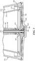
- Fig. 2schematically shows a cross-section of a continuous flow separation device 100 (e.g., a centrifuge bowl 110), in accordance with some embodiments of the present invention.
- the bowl 110has an outer body 120 that defines the structure of the bowl 110 and an inner volume into which the packed red blood cells and wash solution may be introduced for processing.
- the outer body 120includes a main wall 122, a neck portion 126, and shoulder portion 124 that connects the main wall 122 and the neck portion 126.
- the bowl 110is rotatable about an axis 130 in order to separate the packed red blood cells from the wash solution and/or supernatant.
- the bowl 110can include a number of cores that displace some of the volume within the outer body 120, create separation regions in which the red blood cells separate from the wash solution and supernatant, and create a number of fluid paths/channels within the bowl 110.
- the bowl 110may include a top core 140 that fills a significant portion of the inner volume and may be frusto-conical in shape.
- the top core 140includes a top surface 144, a bottom wall 146, and a side wall 142 that extends between the top surface 144 and the bottom wall 146.
- the side wall 142may be spaced from the main wall 122 to create a separation region (e.g., a secondary separation region 115) between the side wall 142 of the top core 140 and the main wall 122 of the outer body 120.
- the top core 140can have a chimney 148 extending through the center from the top surface 144 to the bottom wall 146.
- the chimney 148may serve as a channel through which a number of tubes (e.g., an inlet tube and an extraction tube) can pass.
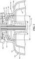
- the bowl 110may also include a bottom core 160 ( Fig. 3 ) located below the top core 130 (e.g., distal to the top core 130).
- the bottom core 160may include a bottom circular wall 162 with an opening 166 extending through it (e.g., near the center of the circular wall 162).
- the bottom core 160may also have a vertical wall 164 that extends upward (e.g., proximally) from the bottom circular wall 162. As shown in Figures 2 and 3 , the vertical wall 164 is located near the outer diameter of the bottom circular wall 162 and may extend upwards such that it is radially outward from the side wall 142 of the top core 140.
- the annular space between the side wall 142 of the top core 140 and the vertical wall 164creates a primary separation region 170 in which the red blood cells begin to separate from the wash solution/supernatant (discussed in greater detail below).
- the bottom core 160 shown in Figure 3is an alternative embodiment of the bottom core 160 shown in Figure 2 (e.g., it is thinner than that shown in Figure 2 ).
- the centrifuge bowl 110can include a upper skirt 182 and a lower skirt 184 both extending radially outward from the center of the bowl 110. Together, the upper skirt 182 and the lower skirt 184 can form an effluent skirt 180 through which waste (e.g., separated wash solution and supernatant) can flow and exit the bowl 110 (e.g., via the waste outlet 230). To that end, the upper skirt 182 and the lower skirt 184 may be spaced from one another such that an effluent channel 186 is formed between the skirts 182/184. The exiting waste can flow through the effluent channel 186 to reach the waste outlet 230.
- wastee.g., separated wash solution and supernatant
- the bowl 110can have an inlet and one or more outlets.
- the bowl 110may include an inlet 190 that may be used to introduce the packed red blood cells and wash solution into the bowl 110.
- some embodiments of the bowl 110may also include an inlet tube 195 that extends downward from the inlet 190, through the chimney 148 in the top core 140, and into an introduction region 200 located between the top core 140 and the bottom core 160.
- the bottom core 160(e.g., the circular wall 162) may be spaced from the bottom 146 of the top core 140 to create a channel 205 extending from the introduction region 200 to the primary separation region 170.
- the centrifugal force created by spinning the bowl 110may cause the packed red blood cells and wash solution entering the introduction region 200 to flow through the channel 205 and into the primary separation region 170.
- the bowl 110may include a bypass seal 210 ( Fig. 4 ) located between the outer diameter of the inlet tube 195 and the inner diameter of the chimney 148.
- the bypass seal 210can be a rotary seal to allow the top core 130 (and the bowl 110) to rotate relative to the inlet tube 195 (which does not rotate during bowl operation).
- the bowl 110can also include a washed red blood cell outlet 220 and a waste outlet 230.
- the washed red blood cell outlet 220can be used to remove washed red blood cells from the bowl 110.
- the washed red blood cell outlet 220may be fluidly connected to a tube (e.g., an extraction tube 225) that extends downward from the washed red blood cell outlet 220, through the chimney 148, through the opening 166 in the bottom core 160 (e.g., within the bottom circular wall 162), and into a washed red blood cell extraction region 240 located below the bottom bore 160 (e.g., between the bottom core 160 and the bottom of the bowl 110).
- the bowl 110can also have a seal 222 (e.g., a rotary seal) between the extraction tube 225 and the opening 166.
- the washed red blood cell pump 55can draw the washed red blood cells out of the extraction region 240, through the extraction tube 225 and out of the washed red blood cell outlet 220.
- the waste outlet 230may be used to remove the waste (e.g., the separated wash solution and supernatant) from the bowl 110.
- the waste outlet 230may be fluidly connected to the effluent channel 186 through the effluent skirt 180. Therefore, when the waste is pushed towards the neck portion 126 (e.g., as discussed in greater detail below), the waste can flow through the effluent channel 186 and out of the waste outlet 230.
- the centrifuge bowl 110may include a rotary seal 250 that connects the ports (e.g., the inlet 190, washed red blood cell outlet port 220, and waste outlet port 230) to the outer body 120 of the bowl 110.
- the rotary seal 250allows the bowl 110 (and the top core 140 and bottom core 160) to spin while the inlet 190, washed red blood cell outlet 220, and waste outlet 230 remain stationary.
- some embodiments of the bowl 110can include a weir disk 260 ( Figure 5 ) that extends radially inward from the bottom of the neck portion 126 of the outer body 120.
- the weir disk 260essentially creates a wall that forces any waste leaving the bowl 110 to a smaller diameter defined by the inner diameter 262 of the opening 264 through the weir disk 260. By reducing this diameter, the weir disk 260 reduces the pressure required to withdraw the washed red blood cells from the bowl 110.
- the weir disk 260creates a fluid channel 270 between the weir disk 260 and the top surface 144 of the top core 140.
- the fluide.g., the waste
- the fluidmay then "roll over" the weir disk 260 (e.g., similar to the overflow of a dam), and fill the region above the weir disk 260 (e.g., the neck portion 126 of the bowl 110) until it comes in contact with the effluent skirt 180.
- the fluide.g., the separated wash solution and/or supernatant
- some embodimentsmay include an optical system 280 located on the bowl 110.
- the optical system 280may include an LED (e.g., a red LED) that emits a beam (e.g., approximately 1-2mm in diameter) that illuminates a small area of the shoulder 124 (or other portion of the bowl 110).
- the optical system 280may also include an optical sensor that is focused on the illuminated area of the bowl shoulder 280 (or other portion of the bowl 110) and determines the location of the red blood cells within the bowl 110 (e.g., based on a signal level received back at the sensor).
- Figure 6is a flowchart depicting a method 600 of washing packed red blood cells in accordance with various embodiments of the present invention.
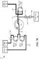
- Figures 7A and 7Bschematically show the system 10 at various stages of the method.
- the usermay install the disposable set shown in Figure 1 into the system 100 (Step 605), for example, by installing the separation device 100 and running the lines 20/30/40/50/60 through their respective valves V1/V7 and pumps 25/35/55.
- the usermay then connect the red blood cell line 20 to the packed red blood cell container 22 (Step 610) and connect the wash solution line 30 to the wash solution container 32 (step 615).
- the system 10/method 600may then start rotating the centrifuge 110.
- the speed at which the system 10/method 600 rotates the separation device 100may depend on a number of factors including, for example, the volume of packed red blood cells to be washed, the hematocrit of the packed red blood cells, etc. However, in some embodiments, the system 10/method 600 may rotate the separation device 100 at speeds between 3500 and 5000 revolutions per minute (e.g., 4000 RPM).
- the system 10may activate the red blood cell pump 25 (Step 625) to start drawing packed red blood cells from the red blood cell container 32 and activate the wash solution pump 35 (Step 630) to start drawing wash solution from the wash solution container 32 ( Fig. 7A ).
- both the red blood cell line 20 and the wash solution line 30are connected to the inlet line 40 (which, in turn, is connected to the inlet 190 of the bowl 110).
- the packed red blood cells and the wash solutionreach the inlet line 40 (and prior to entering the bowl 110), they will mix together and the wash solution will dilute the packed red blood cells prior to entering the bowl 110.
- This dilution and mixing as the packed red blood cells enter the inlet line 40allows the wash solution to essentially get between the packed red blood cells and begin to wash out the supernatant and/or any storage solution contained within the packed red blood cells.
- some embodimentsutilize a packed red blood cell to wash solution flow rate ratio of between 1:2 and 1:5 (e.g., 1:3).
- the flow rate for the packed red blood cellsmay be between 10 and 30 ml/min (e.g., 20 ml/min) and the flow rate for the wash solution may be between 20 and 150 ml/min (e.g., 60 ml/min).
- the packed red blood cell/wash solution mixturee.g., the diluted packed red blood cells
- the inlet tube 195the inlet tube 195 and into the introduction region 200.
- the centrifugal forces from the spinning of the bowl 110will cause the packed red blood cell/wash solution mixture to flow through the channel 205 between the top core 140 and bottom core 160 and into the primary separation region 170 (e.g., between the side wall 142 of the top core 140 and the proximally extending wall 164 of the bottom core), where separation of the packed red blood cells from the wash solution and supernatant begins.
- the packed red blood cell/wash solution mixturewill flow into the secondary separation region 115 where the packed red blood cell/wash solution mixture continues to separate.
- the centrifugal forcescause the heavier cellular components (e.g., the red blood cells) of the mixture to sediment from the lighter wash solution and supernatant.
- the red blood cellswill continue to sediment to the outermost diameter, flow over the proximally extending wall 164 on the bottom core 160, and begin to fill the area between the bottom core 160 and the bottom of the bowl 110.
- the wash solution and supernatante.g., the waste
- the wash solution and supernatantwill move inward towards the center of the bowl 110.
- the separated wash solution/supernatantwill flow through the fluid channel 270 between the weir disk 260 and the top surface 144 of the top core 140, over the weir disk 260, and will exit the bowl 110 via the effluent channel 186 and the waste outlet 230.
- the wastewill then flow through the waste line 60 and into the waste container 62.
- the bowl 110is a continuous flow bowl that allows the continuous washing of the packed red blood cells without the need to intermittently stop.
- various embodiments of the present inventionalso extract washed red blood cells from the bowl 110 as additional packed red blood cell/wash solution mixture is introduced.
- the system/methodmay monitor the volume of washed red blood cells collected under the bottom core 160 (e.g., in the extraction region 240) (Step 635), and when a sufficient volume of washed red blood cells has been pumped into the separation device/bowl 110 (e.g., between 80 and 120 mL, for example, 100 mL), the washed red blood cell pump 55 can begin drawing the washed red blood cells up the extraction tube 225 and out of the washed red blood cell outlet 220 (Step 640; Fig. 7B ). As the washed red blood cells leave the bowl 110, they will pass through line 50 and into the washed red blood cell container 52.
- a sufficient volume of washed red blood cellshas been pumped into the separation device/bowl 110 (e.g., between 80 and 120 mL, for example, 100 mL)
- the washed red blood cell pump 55can begin drawing the washed red blood cells up the extraction tube 225 and out of the washed red blood cell outlet
- the system 10/method 600may continue to monitor the volume of washed red blood cells collected within the bowl and adjust the speed of the washed red blood cell pump 55 accordingly.
- the speed of the washed red blood cell pumpmay range between 10 and 50 mL/min.
- the speed of the washed red blood cell pump 55may be equal to the speed of the red blood cell pump 25 (e.g., 20 ml/min).
- the controllercan reduce the speed of the washed red blood cell pump 55.
- the system 10(or the user) can monitor (e.g., using a weight sensor, volume sensor, and/or load cell) the volume of packed red blood cells remaining within the packed red blood cell container 22 (Step 645) and, when the packed red blood cell container 22 is empty, the system 10/method 600 may stop the packed red blood cell pump 25 (Step 650). Additionally, to maintain some flow of liquid into the bowl 110, the system 10/method 600 may reduce the speed of the wash solution pump 35 (Step 655). For example, the system 10/method 600 may reduce the speed of the wash solution pump 35 to between 10 and 40 ml/min (e.g., 20 ml) to prevent the bowl 110 (e.g., the rotary seal 250) from overheating.
- the system 10/method 600may reduce the speed of the wash solution pump 35 to between 10 and 40 ml/min (e.g., 20 ml) to prevent the bowl 110 (e.g., the rotary seal 250) from overheating.
- the system 10/method 600may stop the washed red blood cell pump 55 (e.g., to stop drawing washed red blood cells from the bowl 110) (Step 665), stop the wash solution pump 35 (Step 670) to stop the flow of wash solution into the bowl 110, and stop the rotation of the bowl 110 (Step 675).
- the usermay isolate (e.g., by heat sealing line 50) the washed red blood cell container 52 from the rest of the system 10 (Step 680) and remove the container 52 for use and/or further processing.
- the usermay then dispose of the rest of the disposable set (e.g., the remaining lines and the bowl 110)(Step 685). It should be noted that, because any wash solution and supernatant remaining in the bowl is waste and will be discarded, there is no need to transfer the wash solution/supernatant to the waste container 62. Rather, the wash solution/supernatant can be disposed of with the bowl 110.
- the various embodiments described aboveare able to efficiently wash-out the supernatant contained within the packed red blood cells and obtain a washed red blood cell product with a high hematocrit level.
- systems and method in accordance with the embodiments described aboveare able to achieve a wash-out of approximately 97% (e.g., 97% of the supernatant is successfully washed out of the packed red blood cells) and a final product hematocrit of greater than 76%.
- the systems and methods describedare continuous, they are able to wash a wide range of starting packed red blood cell volumes.
Landscapes
- Health & Medical Sciences (AREA)
- Heart & Thoracic Surgery (AREA)
- Vascular Medicine (AREA)
- Biomedical Technology (AREA)
- Engineering & Computer Science (AREA)
- Anesthesiology (AREA)
- Cardiology (AREA)
- Hematology (AREA)
- Life Sciences & Earth Sciences (AREA)
- Animal Behavior & Ethology (AREA)
- General Health & Medical Sciences (AREA)
- Public Health (AREA)
- Veterinary Medicine (AREA)
- External Artificial Organs (AREA)
Description
- The present invention relates to washing blood components, and more particularly to washing packed red blood cells using a continuous flow separation device.
- Apheresis is a procedure in which individual blood components can be separated and collected from whole blood temporarily withdrawn from a subject. Typically, whole blood is withdrawn through a needle inserted into a vein of the subjects arm and into a cell separator, such as a centrifugal bowl. Once the whole blood is separated into its various components, one or more of the components can be removed from the centrifugal bowl. The remaining components can be returned to the subject along with optional compensation fluid to make up for the volume of the removed component. The process of drawing and returning continues until the quantity of the desired component has been collected, at which point the process is stopped. A central feature of apheresis systems is that the processed but unwanted components are returned to the donor. Separated blood components may include, for example, a high density component such as red blood cells, an intermediate density component such as platelets or white blood cells, and a lower density component such as plasma.
- After the procedure is complete, the collected blood components may be further processed and/or stored for later use. In some instances, the collected blood components (e.g., red blood cells) may be mixed with a storage solution prior to storage. Although this storage solution may help prolong the life of the stored blood component, in some instances and for some therapeutic treatments, it may need to be removed prior to infusion/transfusion. Additionally, in some instances, the blood component may deteriorate to some degree during storage. To remove the storage solution and any deteriorated component (e.g., lysed cells), it may be beneficial to wash the blood component prior to infusion/transfusion.
US2015/0273132 (A1 ) discloses systems and methods for continuous separation of whole blood involving washing red blood cells. - In accordance with one embodiment of the present invention, a method for continuously washing packed red blood cells includes (1) connecting a wash solution container to a wash solution line and (2) connecting a red blood cell container to a red blood cell line. The wash solution line may fluidly connect the wash solution container and an inlet line of a blood component separation device. The red blood cell line may fluidly connect the red blood cell container and the inlet line of the blood component separation device. The red blood cell container may contain a volume of packed red blood cells. The method may then transfer, at a first flow rate, packed red blood cells from the red blood cell container to the blood component separation device, and transfer, at the same time as the packed red blood cells, wash solution from the wash solution container to the blood component separation device. The wash solution may be transferred at a second flow rate that is greater than the first flow rate. The wash solution may mix with the packed red blood cells in the inlet line to dilute and wash the packed red blood cells (e.g., prior to entering the separation device). The blood component separation device may separate the washed red blood cells from the wash solution and a supernatant.
- The method may also monitor the volume of washed red blood cells collected within the blood component separation device, and begin drawing the washed red blood cells from the blood component separation device (e.g., into a red blood cell product container) when a target volume of red blood cells is collected within the blood component separation device. Additionally or alternatively, the method may monitor the volume of packed red blood cells remaining within the red blood cell container, and stop the transfer of packed red blood cells when the red blood cell container is empty. The method may also reduce the transfer of wash solution from the second flow rate to a third flow rate.
- In some embodiments, transferring the packed red blood cells to the blood component separation device may include pumping, with a red blood cell pump, the packed red blood cells into the blood component separation device. Similarly, transferring wash solution to the blood component separation device may include pumping, with a wash solution pump, the wash solution into the blood component separation device. In such embodiments, the method may stop the red blood cell pump when the red blood cell container is empty and/or stop the wash solution pump when all washed red blood cells have been drawn from the blood component separation device.
- In additional embodiments, the method may monitor the volume of washed red blood cells within the blood component separation device, and stop drawing washed red blood cells from the blood component separation device when no washed red blood cells remain within the blood component separation device. The method may then isolate the red blood cell product container, stop the wash solution pump to stop transferring wash solution to the blood component separation device, and/or stop the centrifuge. The ratio of the first flow rate to the second flow rate may be between 1:2 and 1:5 (e.g., 1:3). The first flow rate may be between 10 and 30 milliliters per minute (e.g., 20 milliliters per minute), the second flow rate may be between 20 and 150 milliliters per minute (e.g., 60 milliliters per minute), and the third flow rate may be between 10 and 40 milliliters per minute (e.g., 20 milliliters per minute). The target volume of washed red blood cells may be between 50 and 150 milliliters (e.g.,100 milliliters). The blood component separation device may be a centrifuge bowl and the wash solution may be saline.
- In accordance with further embodiments of the present invention, a system for continuous washing of packed red blood cells includes a blood component separation device, an inlet line, a red blood cell line, a wash solution line, a washed red blood cell line, and a waste line. The separation device may separate packed red blood cells from a wash solution and a supernatant, and may have an inlet, a red blood cell outlet, and a waste outlet. The inlet line may be fluidly connected to the inlet of the blood component separation device, and may allow dilution of the packed red blood cells with wash solution prior to entering the blood component separation device. The red blood cell line may be fluidly connected to the inlet line and may be connected to a packed red blood cell container. The flow through the red blood cell line may be controlled by a red blood cell pump. The wash solution line may be fluidly connected to the inlet line and a wash solution container, and the flow through the wash solution line may be controlled by a wash solution pump. The washed red blood cell line may be fluidly connected to the red blood cell outlet of the blood component separation device and a red blood cell product container. The flow through the washed red blood cell line may be controlled by a washed red blood cell pump. The waste line may be fluidly connected to the waste outlet of the blood component separation device and a waste container.
- The system may also have a controller that controls the operation of the red blood cell pump, the wash solution pump and the washed red blood cell pump to control fluid flow through the system. Additionally, the system may have a pressure sensor that is located on the washed red blood cell line and measures the pressure within the washed red blood cell line. A line sensor located on the waste line may monitor the fluid passing through the waste line.
- In some embodiments, the blood component separation device may be a centrifuge bowl. In such embodiments, the bowl may include an outer body, a top core, and a separation region. The outer body may be rotatable about a longitudinal axis of the centrifuge bowl and may have (1) a main body defining an interior cavity, (2) a neck portion extending proximal to the main body, and (3) a shoulder connecting the main body and the neck portion. The top core may be located within and rotatable with the outer body, may be coaxial with the outer body, and may include a chimney extending through it along the longitudinal axis of the centrifuge bowl. The separation region may be located between the top core and the outer body, and rotation of the centrifuge bowl may separate the packed red blood cells from the wash solution and supernatant.
- The bowl may also include an inlet port, a first outlet port and a second outlet port. The inlet port may be used to introduce the packed red blood cells and wash solution into the centrifuge bowl. An inlet tube may fluidly connect to and extend distally from the inlet port and through the chimney. The inlet tube may introduce the packed red blood cells and wash solution into an introduction region. The first outlet port may be used to draw washed red blood cells out of the centrifuge bowl, and an extraction tube may extend from the first outlet port to an extraction region. The second outlet port may be fluidly connected to the separation region, and may allow wash solution and supernatant to exit the centrifuge bowl.
- In some embodiments, the bowl may include a bottom core located within and rotatable with the outer body. The bottom core may be located between the bottom of the outer body and the top core, and the extraction region may be located between the bottom wall of the bottom core and the bottom of the outer body. The extraction region may fluidly connect the extraction tube and the separation region. The extraction tube may extend through the bottom core. The bowl may also have a seal member located between the extraction tube and the bottom core that prevents leakage between them.
- In other embodiments, the bottom core may have a proximally extending wall that extends from the bottom wall. The proximally extending wall may be radially outward from at least a portion of the top core. The centrifuge bowl may have a primary separation region defined by the proximally extending wall and at least a portion of the top core. The primary separation region may be fluidly connected to the separation region. The centrifuge bowl may further include a fluid pathway fluidly connecting the inlet tube and the primary separation region. The fluid pathway may extend between a bottom wall of the top core and the bottom wall of the bottom core. The extraction region may be located between the bottom wall of the bottom core and a bottom of the outer body, and the extraction tube may extend into the extraction region. The proximally extending wall may prevent separated wash solution and supernatant from entering the extraction region. The washed red blood cell pump may draw the washed red blood cells from the centrifuge bowl.
- The foregoing features of embodiments will be more readily understood by reference to the following detailed description, taken with reference to the accompanying drawings, in which:
Figure 1 schematically shows a system for washing packed red blood cells using a continuous flow separation device, in accordance with some embodiments of the present invention.Figure 2 schematically shows a cross-sectional view of a continuous flow centrifuge bowl for use within the system shown inFigure 1 , in accordance with illustrative embodiments of the present invention.Figure 3 schematically shows a cross-sectional view of the lower portion of the centrifuge bowl shown inFigure 2 with an alternative bottom core, in accordance with illustrative embodiments of the present invention.Figure 4 schematically shows a cross-sectional view of a bypass seal within the centrifuge bowl shown inFigure 2 , in accordance with illustrative embodiments of the present invention.Figure 5 schematically shows a cross-sectional view of the top portion of the centrifuge bowl shown inFigure 2 , in accordance with illustrative embodiments of the present invention.Figure 6 is a flowchart depicting a method of washing packed red blood cells using the system shown inFigure 1 , in accordance with various embodiments of the present invention.Figures 7A and7B schematically show the system shown inFigure 1 at various stages of the method shown inFigure 6 , in accordance with some embodiments of the present invention.Fig. 1 schematically shows asystem 10 for washing packed red blood cells in accordance with various embodiments of the present invention. Thesystem 10 includes a blood processing device having a blood component separation device 100 (e.g., a continuous flow separation device such as that described withinU.S. Application no. 14/072,220 ) with a processing chamber in which packed red blood cells may be separated from wash solution and supernatant (discussed in greater detail below). To facilitate the introduction of red blood cells into theseparation device 100, thesystem 10 includes a redblood cell line 20 that is connected to a red blood cell container 22 (e.g., a unit of packed red blood cells) containing a volume of packed red blood cells. Similarly, to facilitate the introduction of wash solution (e.g., saline) into theseparation device 100, thesystem 10 may include awash solution line 30 that is connected to awash solution container 32 containing a volume of wash solution/saline. Both the redblood cell line 22 and thewash solution line 32 are fluidly connected to the inlet 190 (Fig. 2 ) of theseparation device 100, for example, via aninlet line 40.- To collect a red blood cell product from the
separation device 100 after processing/washing the packed red blood cells, thesystem 10 includes a washed redblood cell line 50 that fluidly connects to a redblood cell outlet 220 of theseparation device 100 and a red bloodcell product container 52 in which the processed/washed red blood cells may be collected. Additionally, thesystem 10 may include awaste line 60 that fluidly connects to awaste outlet 230 on theseparation device 100 and to awaste container 62 in which any waste product (e.g., removed wash solution and/or supernatant) may be collected. - As discussed in greater detail below, the flow through the red
blood cell line 20, thesaline line 30, and the washed redblood cell line 50 may be controlled via a pump on each of thelines 20/30/50. For example, thesystem 10 may include (1) a redblood cell pump 25 located on the redblood cell line 20 that draws the packed red blood cells from the redblood cell container 22, (2) awash solution pump 35 located on thewash solution line 30 that draws wash solution (e.g., saline) from thewash solution container 32, and (3) a washed redblood cell pump 55 on the washed redblood cell line 50 that draws the washed red blood cells from theseparation device 100. The system controller may control the speed of each of thepumps 25/35/55 to control the flow rate through each of thelines 20/30/50. - At various points, the
system 10 may include valves that allow the user and/or the system 10 (e.g., the controller within the system 10) to appropriately direct fluid through thesystem 10. For example, thesystem 10 may include a valve V1 located on the redblood cell line 20 to selectively prevent and allow packed red blood cells to flow through the redblood cell line 20. Similarly, thesystem 10 may include a valve V7 on thewaste line 60 to selectively prevent and allow fluid flow through the waste line 60 (e.g., an into the waste container 62). Additionally, although not shown, thesystem 10 may include a valve on thesaline line 30 to stop the flow of saline from thesaline container 32 as needed. - To monitor the fluid exiting the blood
component separation device 100 and flowing into through thewaste line 60, thesystem 10 may include aline sensor 64 located on thewaste line 60. For example, theline sensor 64 may be an optical sensor that consists of an LED which emits light through fluid (e.g., saline and/or blood components) passing through thewaste line 60 and a photo detector which receives the light after it passes through the fluid. The amount of light received by the photo detector is correlated to the density of the fluid passing through the line. For example, when wash solution is leaving theseparation device 100, the amount of light received by the photo detector will be greater than if red blood cells are passing through the waste line 60 (e.g., the level of transmission is greater for the wash solution as compared to red blood cells). Theline sensor 64 may be in communication with the system controller to allow the controller to adjust the speed of thepumps 25/35/55. For example, if theline sensor 64 detects red blood cells within thewaste line 60, the controller may lower the speed of the packed redblood cell pump 25. - It should be noted that, in many applications, it is important to monitor the pressures within the
system 10 andlines 20/30/40/50/60 to ensure that thesystem 10 is operating properly and the pressure within thesystem 10 is not too high or too low. To that end, thesystem 10 may include pressure sensors on one or more of thelines 20/30/40/50/60 to measure the pressures at various points in thesystem 10. For example, thesystem 10 may include a pressure sensor PI on the washed redblood cell line 50 and/or a pressure sensor P2 on thewaste line 60. These pressure sensors P1/P2 monitor the pressures within theirrespective lines 50/60 to ensure that the pressures do not go above or below a threshold (e.g., which can indicate a problem with the procedure and/orsystem 10, such as a problem with the integrity of the seal on the separation device 100). The pressure sensors P1/P2 may be in communication with the controller such that, if the pressure drops below or goes above a threshold, the controller may adjust the flow rates through thelines 20/30/40/50/60 (e.g., by adjusting thepumps 25/35/55), and/or stop the procedure. Fig. 2 schematically shows a cross-section of a continuous flow separation device 100 (e.g., a centrifuge bowl 110), in accordance with some embodiments of the present invention. Thebowl 110 has anouter body 120 that defines the structure of thebowl 110 and an inner volume into which the packed red blood cells and wash solution may be introduced for processing. Theouter body 120, in turn, includes amain wall 122, aneck portion 126, andshoulder portion 124 that connects themain wall 122 and theneck portion 126. As discussed in greater detail below, thebowl 110 is rotatable about anaxis 130 in order to separate the packed red blood cells from the wash solution and/or supernatant.- Within the interior of the
outer body 120, thebowl 110 can include a number of cores that displace some of the volume within theouter body 120, create separation regions in which the red blood cells separate from the wash solution and supernatant, and create a number of fluid paths/channels within thebowl 110. For example, thebowl 110 may include atop core 140 that fills a significant portion of the inner volume and may be frusto-conical in shape. Thetop core 140 includes atop surface 144, abottom wall 146, and aside wall 142 that extends between thetop surface 144 and thebottom wall 146. Theside wall 142 may be spaced from themain wall 122 to create a separation region (e.g., a secondary separation region 115) between theside wall 142 of thetop core 140 and themain wall 122 of theouter body 120. Additionally, thetop core 140 can have achimney 148 extending through the center from thetop surface 144 to thebottom wall 146. Thechimney 148 may serve as a channel through which a number of tubes (e.g., an inlet tube and an extraction tube) can pass. - The
bowl 110 may also include a bottom core 160 (Fig. 3 ) located below the top core 130 (e.g., distal to the top core 130). Thebottom core 160 may include a bottomcircular wall 162 with anopening 166 extending through it (e.g., near the center of the circular wall 162). Thebottom core 160 may also have avertical wall 164 that extends upward (e.g., proximally) from the bottomcircular wall 162. As shown inFigures 2 and3 , thevertical wall 164 is located near the outer diameter of the bottomcircular wall 162 and may extend upwards such that it is radially outward from theside wall 142 of thetop core 140. The annular space between theside wall 142 of thetop core 140 and thevertical wall 164 creates aprimary separation region 170 in which the red blood cells begin to separate from the wash solution/supernatant (discussed in greater detail below). Although similar, it is important to note that thebottom core 160 shown inFigure 3 is an alternative embodiment of thebottom core 160 shown inFigure 2 (e.g., it is thinner than that shown inFigure 2 ). - As best shown within
Figure 5 , within theneck portion 126 of theouter body 120, thecentrifuge bowl 110 can include aupper skirt 182 and alower skirt 184 both extending radially outward from the center of thebowl 110. Together, theupper skirt 182 and thelower skirt 184 can form aneffluent skirt 180 through which waste (e.g., separated wash solution and supernatant) can flow and exit the bowl 110 (e.g., via the waste outlet 230). To that end, theupper skirt 182 and thelower skirt 184 may be spaced from one another such that aneffluent channel 186 is formed between theskirts 182/184. The exiting waste can flow through theeffluent channel 186 to reach thewaste outlet 230. - In order to facilitate the transfer of fluids (e.g., packed red blood cells, wash solution, washed red blood cells, and waste) in and out of the
centrifuge bowl 110, thebowl 110 can have an inlet and one or more outlets. For example, thebowl 110 may include aninlet 190 that may be used to introduce the packed red blood cells and wash solution into thebowl 110. In many blood processing procedures, it is desirable to introduce the incoming blood components (e.g., the packed red blood cells) into an area near the bottom of thebowl 110. To that end, some embodiments of thebowl 110 may also include aninlet tube 195 that extends downward from theinlet 190, through thechimney 148 in thetop core 140, and into anintroduction region 200 located between thetop core 140 and thebottom core 160. Additionally, the bottom core 160 (e.g., the circular wall 162) may be spaced from thebottom 146 of thetop core 140 to create achannel 205 extending from theintroduction region 200 to theprimary separation region 170. The centrifugal force created by spinning thebowl 110 may cause the packed red blood cells and wash solution entering theintroduction region 200 to flow through thechannel 205 and into theprimary separation region 170. - It is important to note that problems can arise if the fluid introduced into the bowl 110 (e.g., into the introduction region 200) flows back up into the chimney 148 (e.g., instead of traveling towards the outer diameter of the
bowl 110 and into the separation regions). For example, if this "bypass" occurs while thebowl 110 is being filled, some of the fluid (e.g., packed red blood cells, wash solution, etc.) may flow up thechimney 148, and into the region around theeffluent skirt 180. This, in turn, may reduce the collection efficiency of the system and/or negatively impact the quality of the final product (e.g., the hematocrit of the washed red blood cells). In order to avoid this "bypass" and isolate theintroduction region 200 from thechimney 148 in thetop core 130, thebowl 110 may include a bypass seal 210 (Fig. 4 ) located between the outer diameter of theinlet tube 195 and the inner diameter of thechimney 148. Thebypass seal 210 can be a rotary seal to allow the top core 130 (and the bowl 110) to rotate relative to the inlet tube 195 (which does not rotate during bowl operation). - In addition to the
inlet 190, thebowl 110 can also include a washed redblood cell outlet 220 and awaste outlet 230. As the name suggests, the washed redblood cell outlet 220 can be used to remove washed red blood cells from thebowl 110. Additionally, in a manner similar to theinlet 190, the washed redblood cell outlet 220 may be fluidly connected to a tube (e.g., an extraction tube 225) that extends downward from the washed redblood cell outlet 220, through thechimney 148, through theopening 166 in the bottom core 160 (e.g., within the bottom circular wall 162), and into a washed red bloodcell extraction region 240 located below the bottom bore 160 (e.g., between thebottom core 160 and the bottom of the bowl 110). To prevent leakage past the bottom core 160 (e.g., through opening 166), thebowl 110 can also have a seal 222 (e.g., a rotary seal) between theextraction tube 225 and theopening 166. As discussed in greater detail below, the washed redblood cell pump 55 can draw the washed red blood cells out of theextraction region 240, through theextraction tube 225 and out of the washed redblood cell outlet 220. - The
waste outlet 230 may be used to remove the waste (e.g., the separated wash solution and supernatant) from thebowl 110. To that end, thewaste outlet 230 may be fluidly connected to theeffluent channel 186 through theeffluent skirt 180. Therefore, when the waste is pushed towards the neck portion 126 (e.g., as discussed in greater detail below), the waste can flow through theeffluent channel 186 and out of thewaste outlet 230. - As best shown in
Figures 2 and5 , thecentrifuge bowl 110 may include arotary seal 250 that connects the ports (e.g., theinlet 190, washed red bloodcell outlet port 220, and waste outlet port 230) to theouter body 120 of thebowl 110. Therotary seal 250 allows the bowl 110 (and thetop core 140 and bottom core 160) to spin while theinlet 190, washed redblood cell outlet 220, andwaste outlet 230 remain stationary. - In order to reduce the pressure required to withdraw the washed red blood cells, some embodiments of the
bowl 110 can include a weir disk 260 (Figure 5 ) that extends radially inward from the bottom of theneck portion 126 of theouter body 120. Theweir disk 260 essentially creates a wall that forces any waste leaving thebowl 110 to a smaller diameter defined by theinner diameter 262 of theopening 264 through theweir disk 260. By reducing this diameter, theweir disk 260 reduces the pressure required to withdraw the washed red blood cells from thebowl 110. - As shown in
Figure 5 , theweir disk 260 creates afluid channel 270 between theweir disk 260 and thetop surface 144 of thetop core 140. As thebowl 110 fills with fluid, the fluid (e.g., the waste) will flow through thefluid channel 270 between theweir disk 260 and thetop surface 144 of thetop core 140 until it reaches theopening 264 in theweir disk 260. The fluid may then "roll over" the weir disk 260 (e.g., similar to the overflow of a dam), and fill the region above the weir disk 260 (e.g., theneck portion 126 of the bowl 110) until it comes in contact with theeffluent skirt 180. The fluid (e.g., the separated wash solution and/or supernatant) may then be pushed from thebowl 110 into theeffluent channel 186 and into thewaste outlet 230. - During processing (e.g., washing of the packed red blood cells) it may be important to know not only how full the
bowl 110 is but also the location of the washed red blood cells and/or the volume of the washed red blood cells within thebowl 110. To that end, some embodiments may include anoptical system 280 located on thebowl 110. Theoptical system 280 may include an LED (e.g., a red LED) that emits a beam (e.g., approximately 1-2mm in diameter) that illuminates a small area of the shoulder 124 (or other portion of the bowl 110). Additionally, theoptical system 280 may also include an optical sensor that is focused on the illuminated area of the bowl shoulder 280 (or other portion of the bowl 110) and determines the location of the red blood cells within the bowl 110 (e.g., based on a signal level received back at the sensor). Figure 6 is a flowchart depicting amethod 600 of washing packed red blood cells in accordance with various embodiments of the present invention.Figures 7A and7B schematically show thesystem 10 at various stages of the method. First, the user may install the disposable set shown inFigure 1 into the system 100 (Step 605), for example, by installing theseparation device 100 and running thelines 20/30/40/50/60 through their respective valves V1/V7 and pumps 25/35/55. Once the disposable set is installed, the user may then connect the redblood cell line 20 to the packed red blood cell container 22 (Step 610) and connect thewash solution line 30 to the wash solution container 32 (step 615).- After the disposable set is installed and the red
blood cell line 20 andwash solution line 30 are connected, thesystem 10/method 600 may then start rotating thecentrifuge 110. The speed at which thesystem 10/method 600 rotates the separation device 100 (e.g., bowl 110) may depend on a number of factors including, for example, the volume of packed red blood cells to be washed, the hematocrit of the packed red blood cells, etc. However, in some embodiments, thesystem 10/method 600 may rotate theseparation device 100 at speeds between 3500 and 5000 revolutions per minute (e.g., 4000 RPM). Once thebowl 110 is up to speed, the system 10 (e.g., the controller) may activate the red blood cell pump 25 (Step 625) to start drawing packed red blood cells from the redblood cell container 32 and activate the wash solution pump 35 (Step 630) to start drawing wash solution from the wash solution container 32 (Fig. 7A ). - As mentioned above, both the red
blood cell line 20 and thewash solution line 30 are connected to the inlet line 40 (which, in turn, is connected to theinlet 190 of the bowl 110). To that end, as the packed red blood cells and the wash solution reach the inlet line 40 (and prior to entering the bowl 110), they will mix together and the wash solution will dilute the packed red blood cells prior to entering thebowl 110. This dilution and mixing as the packed red blood cells enter theinlet line 40 allows the wash solution to essentially get between the packed red blood cells and begin to wash out the supernatant and/or any storage solution contained within the packed red blood cells. - It is important to note that the flow rates at which the packed red blood cells and wash solution are drawn from their
respective containers 22/32 (and the ratio between the flow rates) and introduced into thebowl 110 impact the level of washing of the packed red blood cells (e.g., how much supernatant is washed out of the red blood cells). To that end, some embodiments utilize a packed red blood cell to wash solution flow rate ratio of between 1:2 and 1:5 (e.g., 1:3). For example, the flow rate for the packed red blood cells may be between 10 and 30 ml/min (e.g., 20 ml/min) and the flow rate for the wash solution may be between 20 and 150 ml/min (e.g., 60 ml/min). - As the packed red blood cell/wash solution mixture (e.g., the diluted packed red blood cells) enters the
bowl 110 through theinlet 190, it will flow down theinlet tube 195 and into theintroduction region 200. Once in theintroduction region 200, the centrifugal forces from the spinning of thebowl 110 will cause the packed red blood cell/wash solution mixture to flow through thechannel 205 between thetop core 140 andbottom core 160 and into the primary separation region 170 (e.g., between theside wall 142 of thetop core 140 and theproximally extending wall 164 of the bottom core), where separation of the packed red blood cells from the wash solution and supernatant begins. - As additional packed red blood cell/wash solution mixture is introduced into the
bowl 110, the packed red blood cell/wash solution mixture will flow into thesecondary separation region 115 where the packed red blood cell/wash solution mixture continues to separate. For example, as the packed red blood cell/wash solution mixture enters thesecondary separation region 115 of thebowl 110, the centrifugal forces cause the heavier cellular components (e.g., the red blood cells) of the mixture to sediment from the lighter wash solution and supernatant. As thebowl 110 continues to fill with the packed red blood cell/wash solution mixture, the red blood cells will continue to sediment to the outermost diameter, flow over theproximally extending wall 164 on thebottom core 160, and begin to fill the area between thebottom core 160 and the bottom of thebowl 110. As additional washed red blood cells collect, they will begin to pack, increasing the hematocrit of the final product. Additionally, the wash solution and supernatant (e.g., the waste) will move inward towards the center of thebowl 110. When thebowl 110 is full, the separated wash solution/supernatant will flow through thefluid channel 270 between theweir disk 260 and thetop surface 144 of thetop core 140, over theweir disk 260, and will exit thebowl 110 via theeffluent channel 186 and thewaste outlet 230. The waste will then flow through thewaste line 60 and into thewaste container 62. - As mentioned above, the
bowl 110 is a continuous flow bowl that allows the continuous washing of the packed red blood cells without the need to intermittently stop. To that end, various embodiments of the present invention also extract washed red blood cells from thebowl 110 as additional packed red blood cell/wash solution mixture is introduced. For example, the system/method may monitor the volume of washed red blood cells collected under the bottom core 160 (e.g., in the extraction region 240) (Step 635), and when a sufficient volume of washed red blood cells has been pumped into the separation device/bowl 110 (e.g., between 80 and 120 mL, for example, 100 mL), the washed redblood cell pump 55 can begin drawing the washed red blood cells up theextraction tube 225 and out of the washed red blood cell outlet 220 (Step 640;Fig. 7B ). As the washed red blood cells leave thebowl 110, they will pass throughline 50 and into the washed redblood cell container 52. - To ensure that the washed red
blood cell pump 55 does not draw the washed red blood cells too quickly and ensure that waste solution is not accidentally drawn out of thebowl 110 through the washed redblood cell outlet 220, thesystem 10/method 600 may continue to monitor the volume of washed red blood cells collected within the bowl and adjust the speed of the washed redblood cell pump 55 accordingly. For example, the speed of the washed red blood cell pump may range between 10 and 50 mL/min. In some embodiments, the speed of the washed redblood cell pump 55 may be equal to the speed of the red blood cell pump 25 (e.g., 20 ml/min). However, if the system/method detects that the volume of washed red blood cells within thebowl 110 is too low and there is a risk that waste may be drawn up with the washed red blood cells, the controller can reduce the speed of the washed redblood cell pump 55. - During this time, the system 10 (or the user) can monitor (e.g., using a weight sensor, volume sensor, and/or load cell) the volume of packed red blood cells remaining within the packed red blood cell container 22 (Step 645) and, when the packed red
blood cell container 22 is empty, thesystem 10/method 600 may stop the packed red blood cell pump 25 (Step 650). Additionally, to maintain some flow of liquid into thebowl 110, thesystem 10/method 600 may reduce the speed of the wash solution pump 35 (Step 655). For example, thesystem 10/method 600 may reduce the speed of thewash solution pump 35 to between 10 and 40 ml/min (e.g., 20 ml) to prevent the bowl 110 (e.g., the rotary seal 250) from overheating. - Once all of the red blood cells have been collected from the bowl 110 (Step 660), the
system 10/method 600 may stop the washed red blood cell pump 55 (e.g., to stop drawing washed red blood cells from the bowl 110) (Step 665), stop the wash solution pump 35 (Step 670) to stop the flow of wash solution into thebowl 110, and stop the rotation of the bowl 110 (Step 675). Once thepumps 25/35 andbowl 110 are stopped, the user may isolate (e.g., by heat sealing line 50) the washed redblood cell container 52 from the rest of the system 10 (Step 680) and remove thecontainer 52 for use and/or further processing. The user may then dispose of the rest of the disposable set (e.g., the remaining lines and the bowl 110)(Step 685). It should be noted that, because any wash solution and supernatant remaining in the bowl is waste and will be discarded, there is no need to transfer the wash solution/supernatant to thewaste container 62. Rather, the wash solution/supernatant can be disposed of with thebowl 110. - It should be noted that the various embodiments described above are able to efficiently wash-out the supernatant contained within the packed red blood cells and obtain a washed red blood cell product with a high hematocrit level. In particular, systems and method in accordance with the embodiments described above are able to achieve a wash-out of approximately 97% (e.g., 97% of the supernatant is successfully washed out of the packed red blood cells) and a final product hematocrit of greater than 76%. Also, because the systems and methods described are continuous, they are able to wash a wide range of starting packed red blood cell volumes.
- It is also important to note that, although the above described system and methods utilize a centrifuge bowl for washing the packed red blood cells, some embodiments of the present invention can be used with different separation devices. For example, the methods described above may be used with "belt" type separation devices such as the Cobe® Spectra system or Cobe® 2991 Cell Processor by Terumo BCT.
- The embodiments of the invention described above are intended to be merely exemplary; variations and modifications will be apparent to those skilled in the art. The invention is defined by the appended claims.
Claims (15)
- A method for continuously washing packed red blood cells comprising:(a) connecting a wash solution container (32) to a wash solution line (30), the wash solution line fluidly connecting the wash solution container and an inlet line of a blood component separation device (100);(b) connecting a red blood cell container (22) to a red blood cell line (20), the red blood cell line fluidly connecting the red blood cell container and the inlet line of the blood component separation device, the red blood cell container containing a volume of packed red blood cells;(c) transferring, at a first flow rate, packed red blood cells from the red blood cell container to the blood component separation device;(d) transferring, at the same time as step (c), wash solution from the wash solution container to the blood component separation device, the wash solution being transferred at a second flow rate that is greater than the first flow rate, the wash solution mixing with the packed red blood cells in the inlet line, thereby diluting and washing the packed red blood cells, the blood component separation device separating washed red blood cells from the wash solution and a supernatant;(e) monitoring a volume of washed red blood cells collected within the blood component separation device;(f) drawing washed red blood cells from the blood component separation device and into a red blood cell product container when a target volume of red blood cells is collected within the blood component separation device;(g) monitoring a volume of packed red blood cells remaining within the red blood cell container; and(h) stopping, when the red blood cell container is empty, the transfer of packed red blood cells and reducing the transfer of wash solution from the second flow rate to a third flow rate.
- A method according to claim 1, wherein transferring packed red blood cells to the blood component separation device includes pumping, with a red blood cell pump, the packed red blood cells into the blood component separation device and, optionally, stopping the red blood cell pump when the red blood cell container is empty.
- A method according to claim 1, wherein transferring wash solution to the blood component separation device includes pumping, with a wash solution pump, the wash solution into the blood component separation device and, optionally, stopping the wash solution pump when all washed red blood cells have been drawn from the blood component separation device.
- A method according to claim 1, further comprising:(i) monitoring the volume of washed red blood cells within the blood component separation device; and(j) stopping the drawing of washed red blood cells from the blood component separation device when no washed red blood cells remain within the blood component separation device; and, optionally,isolating the red blood cell product container after step (j), or
stopping the wash solution pump after step (j) to stop transferring wash solution to the blood component separation device, or
stopping the centrifuge after step (j). - A method according to claim 1, wherein a ratio of the first flow rate to the second flow rate is one of: between 1:2 and 1:5; and 1:3, and/or wherein the first flow rate is one of: between 10 and 30 milliliters per minute; and 20 milliliters per minute.
- A method according to claim 1, wherein the target volume of washed red blood cells is between 50 and 150 milliliters, and/or wherein the target volume of washed red blood cells is 100 milliliters.
- A method according to claim 1, wherein the blood component separation device is a centrifuge bowl, and/or wherein the wash solution is saline.
- A system for continuous washing of packed red blood cells comprising:a blood component separation device (100) configured to separate packed red blood cells from a wash solution and a supernatant, the blood component separation device having an inlet, a red blood cell outlet, and a waste outlet;an inlet line (40) fluidly connected to the inlet of the blood component separation device, the inlet line configured to allow dilution of the packed red blood cells with wash solution prior to entering the blood component separation device;a red blood cell line (20) fluidly connected to the inlet line and configured to connect to a packed red blood cell container (22), the flow through the red blood cell line being controlled by a red blood cell pump (25);a wash solution line (30) fluidly connected to the inlet line and configured to connect to a wash solution container (32), the flow through the wash solution line being controlled by a wash solution pump (35);a washed red blood cell line (50) fluidly connected to the red blood cell outlet (220) of the blood component separation device and a red blood cell product container (52), the flow through the washed red blood cell line being controlled by a washed red blood cell pump (55); anda waste line (60) fluidly connected to the waste outlet of the blood component separation device and a waste container (62).
- A system according to claim 8, further comprising:a controller configured to control the operation of the red blood cell pump, the wash solution pump and the washed red blood cell pump to control fluid flow through the system, and/ora pressure sensor located on the washed red blood cell line, the pressure sensor configured to measure a pressure within the washed red blood cell line, and/ora line sensor located on the waste line, the line sensor configured to monitor a fluid passing through the waste line.
- A system according to claim 8, wherein the blood component separation device is a centrifuge bowl, the centrifuge bowl optionally including:an outer body rotatable about a longitudinal axis of the centrifuge bowl, the outer body having a main body defining an interior cavity, a neck portion extending proximal to the main body, and a shoulder connecting the main body and the neck portion;a top core located within and rotatable with the outer body, the top core being coaxial with the outer body and including a chimney extending through the top core along the longitudinal axis of the centrifuge bowl;a separation region located between the top core and the outer body, rotation of the centrifuge bowl separating the packed red blood cells from the wash solution and supernatant;an inlet port for introducing packed red blood cells and wash solution into the centrifuge bowl;an inlet tube fluidly connected to and extending distally from the inlet port and through the chimney, the inlet tube configured to introduce the packed red blood cells and wash solution into an introduction region;a first outlet port for drawing a washed red blood cells out of the centrifuge bowl;an extraction tube extending from the first outlet port to an extraction region; anda second outlet port fluidly connected to the separation region, the second outlet port configured to allow wash solution and supernatant to exit the centrifuge bowl.
- A system according to claim 10, wherein the centrifuge bowl further includes a bottom core located within and rotatable with the outer body, the bottom core located between a bottom of the outer body and the top core, the extraction region located between a bottom wall of the bottom core and the bottom of the outer body, the extraction region fluidly connecting the extraction tube and the separation region, wherein, optionally, the extraction tube extends through the bottom core.
- A system according to claim 11, wherein the centrifuge bowl further includes a seal member located between the extraction tube and the bottom core, the seal member preventing leakage between the extraction tube and the bottom core, or wherein the bottom core includes a proximally extending wall extending from the bottom wall, the proximally extending wall being radially outward from at least a portion of the top core, and, optionally, wherein the centrifuge bowl further includes a primary separation region defined by the proximally extending wall and at least a portion of the top core, and optionally
wherein the primary separation region is fluidly connected to the separation region. - A system according to claim 12, wherein the centrifuge bowl further includes a fluid pathway fluidly connecting the inlet tube and the primary separation region and, optionally wherein the fluid pathway extends between a bottom wall of the top core and the bottom wall of the bottom core.
- A system according to claim 12, wherein the extraction region is located between the bottom wall of the bottom core and a bottom of the outer body, the extraction tube extending into the extraction region, and/or wherein the proximally extending wall prevents separated wash solution and supernatant from entering the extraction region.
- A system according to claim 8, wherein the washed red blood cell pump is configured to draw washed red blood cells from the centrifuge bowl.
Applications Claiming Priority (2)
| Application Number | Priority Date | Filing Date | Title |
|---|---|---|---|
| US201662354162P | 2016-06-24 | 2016-06-24 | |
| PCT/US2017/038761WO2017223318A1 (en) | 2016-06-24 | 2017-06-22 | System and Method for Continuous Flow Red Blood Cell Washing |
Publications (3)
| Publication Number | Publication Date |
|---|---|
| EP3474923A1 EP3474923A1 (en) | 2019-05-01 |
| EP3474923A4 EP3474923A4 (en) | 2020-02-26 |
| EP3474923B1true EP3474923B1 (en) | 2021-06-16 |
Family
ID=60784849
Family Applications (1)
| Application Number | Title | Priority Date | Filing Date |
|---|---|---|---|
| EP17816211.1AActiveEP3474923B1 (en) | 2016-06-24 | 2017-06-22 | System and method for continuous flow red blood cell washing |
Country Status (3)
| Country | Link |
|---|---|
| US (1) | US11541161B2 (en) |
| EP (1) | EP3474923B1 (en) |
| WO (1) | WO2017223318A1 (en) |
Families Citing this family (1)
| Publication number | Priority date | Publication date | Assignee | Title |
|---|---|---|---|---|
| EP3476754B1 (en)* | 2017-10-24 | 2019-10-02 | Grifols Worldwide Operations Limited | Apparatus for gravity-emptying bottles containing frozen blood product comprising a unit for monitoring emptying and emptying method |
Family Cites Families (112)
| Publication number | Priority date | Publication date | Assignee | Title |
|---|---|---|---|---|
| US3655123A (en) | 1966-08-08 | 1972-04-11 | Us Health Education & Welfare | Continuous flow blood separator |
| US3645252A (en) | 1968-12-05 | 1972-02-29 | Gilford Instr Labor Inc | Apparatus for sampling blood or the like fluid |
| US3768653A (en) | 1972-03-21 | 1973-10-30 | R Brumfield | Filtering cardiotomy reservoir |
| US4189470A (en) | 1973-01-30 | 1980-02-19 | Bio-Response, Inc. | Method for the continuous removal of a specific antibody from the lymph fluid in animals and humans |
| US4054523A (en) | 1973-07-10 | 1977-10-18 | General Electric Company | Cardiotomy reservoir with integral filter |
| US3965896A (en) | 1974-06-17 | 1976-06-29 | Swank Roy L | Blood autotransfusion method and apparatus |
| US4033345A (en) | 1975-11-13 | 1977-07-05 | Sorenson Research Co., Inc. | Autologous transfusion filter system and method |
| US4086924A (en) | 1976-10-06 | 1978-05-02 | Haemonetics Corporation | Plasmapheresis apparatus |
| US4049192A (en)* | 1976-11-01 | 1977-09-20 | Union Carbide Corporation | Blood washing method using a saline wash solution of varying concentration for use with blood washing apparatus |
| US4115277A (en) | 1977-06-17 | 1978-09-19 | Pioneer Filters, Inc. | Blood filtering apparatus of graduated fiber density |
| US4151844A (en) | 1977-11-11 | 1979-05-01 | Baxter Travenol Laboratories, Inc. | Method and apparatus for separating whole blood into its components and for automatically collecting one component |
| US4681677A (en) | 1978-02-17 | 1987-07-21 | Olin Corporation | Water processor having automatic shutoff and bypass means |
| US4243531A (en) | 1978-05-30 | 1981-01-06 | Baxter Travenol Laboratories, Inc. | Cardiotomy reservoir |
| SE432000B (en) | 1978-07-18 | 1984-03-12 | Mo Och Domsjoe Ab | PROCEDURE FOR REGULATING THE DEGREE OF CUSTOMIZATION IN THE PREPARATION OF WHITE WIRELESS DEVICE FOR EXECUTING THE PROCEDURE |
| US4411786A (en) | 1979-09-07 | 1983-10-25 | Russell Richard T | Method and apparatus for separating blood from other fluids during operative procedures |
| US4321192A (en) | 1980-01-10 | 1982-03-23 | Ionics Incorporated | Fractionation of protein mixtures by salt addition followed by dialysis treatment |
| US4416654A (en) | 1981-09-03 | 1983-11-22 | Haemonetics Corporation | Pheresis apparatus |
| US4482342A (en) | 1982-06-17 | 1984-11-13 | Haemonetics Corporation | Blood processing system for cell washing |
| US4680025A (en) | 1982-08-24 | 1987-07-14 | Baxter Travenol Laboratories, Inc. | Blood component collection systems and methods |
| EP0118473A4 (en) | 1982-08-24 | 1985-09-16 | Baxter Travenol Lab | Increased yield blood component collection systems and methods. |
| US4704203A (en) | 1982-08-27 | 1987-11-03 | Reed Charles C | Cardiotomy reservoir apparatus and method |
| DE3304951A1 (en) | 1983-02-12 | 1984-08-16 | Akzo Gmbh, 5600 Wuppertal | DEVICE FOR FILTERING A LIQUID |
| US4743371A (en) | 1983-04-08 | 1988-05-10 | Shiley, Inc. | Blood filter |
| US4561868A (en) | 1984-07-02 | 1985-12-31 | Von Reis Charles | Canister filter assembly |
| US4673423A (en) | 1985-07-23 | 1987-06-16 | Mack Trucks, Inc. | Split flow particulate filter |
| SE453360B (en) | 1985-11-18 | 1988-02-01 | Gambro Lundia Ab | AUTOT TRANSFUSION SYSTEM FOR COLLECTING, TREATING AND RETURNING A PATIENT'S BLOOD |
| DE3541521A1 (en) | 1985-11-23 | 1987-06-04 | Sartorius Gmbh | FILTERS FOR FILTERING HUMAN BLOOD, ESPECIALLY IN AN EXTRACORPORAL CIRCUIT |
| US5133703A (en) | 1986-02-18 | 1992-07-28 | Boehringer Laboratories | Process and apparatus for collecting blood of a patient for autotransfusion |
| US4781707A (en) | 1986-02-18 | 1988-11-01 | Boehringer Laboratories | Process and apparatus for collecting blood from a body cavity for autotransfusion |
| US4828543A (en) | 1986-04-03 | 1989-05-09 | Weiss Paul I | Extracorporeal circulation apparatus |
| SE8601891D0 (en) | 1986-04-24 | 1986-04-24 | Svante Jonsson | PLASMA SWITCH TREATMENT AND TROMBOCYTING MACHINE |
| US4668214A (en) | 1986-06-09 | 1987-05-26 | Electromedics, Inc. | Method of washing red blood cells |
| FR2600537B1 (en) | 1986-06-24 | 1990-02-16 | Evelyne Lasnier | AUTOTRANSFUSER. |
| US4943273A (en) | 1986-07-22 | 1990-07-24 | Haemonetics Corporation | Disposable centrifuge bowl for blood processing |
| US4946434A (en) | 1986-07-22 | 1990-08-07 | Haemonetics Corporation | Disposable manifold and valve |
| US4795448A (en) | 1986-08-08 | 1989-01-03 | Haemonetics Corporation | Suction collection system |
| DE3772749D1 (en)* | 1986-08-11 | 1991-10-10 | Baxter Int | BLOOD CELL WASHING SYSTEM AND METHOD. |
| US4834890A (en) | 1987-01-30 | 1989-05-30 | Baxter International Inc. | Centrifugation pheresis system |
| US5076911A (en) | 1987-01-30 | 1991-12-31 | Baxter International Inc. | Centrifugation chamber having an interface detection surface |
| US4806252A (en) | 1987-01-30 | 1989-02-21 | Baxter International Inc. | Plasma collection set and method |
| JPS63229061A (en) | 1987-03-18 | 1988-09-22 | テルモ株式会社 | Membrane type artificial lung and its production |
| US4828716A (en) | 1987-04-03 | 1989-05-09 | Andronic Devices, Ltd. | Apparatus and method for separating phases of blood |
| WO1989001792A1 (en) | 1987-08-28 | 1989-03-09 | Haemonetics Corporation | Method and apparatus for cell washing |
| US4851126A (en) | 1987-11-25 | 1989-07-25 | Baxter International Inc. | Apparatus and methods for generating platelet concentrate |
| US4872988A (en) | 1988-02-02 | 1989-10-10 | Culkin Joseph B | Method and device for separation of colloidal suspensions |
| FR2628974A1 (en) | 1988-03-25 | 1989-09-29 | Hospal Ind | INTEGRATED DEVICE FOR THE BIOSPECIFIC PURIFICATION OF A LIQUID COMPRISING CELLULAR ELEMENTS |
| US5419759A (en) | 1988-11-17 | 1995-05-30 | Naficy; Sadeque S. | Apparatus and methods for treatment of HIV infections and AIDS |
| US4954251A (en) | 1989-01-31 | 1990-09-04 | Miles Inc. | Concentric microaggregate blood filter |
| US5055198A (en) | 1990-03-07 | 1991-10-08 | Shettigar U Ramakrishna | Autologous blood recovery membrane system and method |
| US5215519A (en) | 1990-03-07 | 1993-06-01 | Shettigar U Ramakrishna | Autotransfusion membrane system with means for providing reverse filtration |
| US5234403A (en) | 1990-05-25 | 1993-08-10 | Sumitomo Bakelite Co., Ltd. | Blood collecting apparatus |
| US5110557A (en) | 1990-07-09 | 1992-05-05 | Brown Bradley V | Blood sample collection apparatus |
| US5182019A (en) | 1990-08-17 | 1993-01-26 | Zenon Environmental Inc. | Cartridge of hybrid frameless arrays of hollow fiber membranes and module containing an assembly of cartridges |
| US5141486B1 (en) | 1990-11-05 | 1996-01-30 | Cobe Lab | Washing cells |
| JPH04236960A (en) | 1991-01-21 | 1992-08-25 | Sumitomo Bakelite Co Ltd | Blood recovering and transfusing device |
| US5135645A (en) | 1991-03-28 | 1992-08-04 | Raytheon Company | Refrigerator water filter |
| US5273517A (en) | 1991-07-09 | 1993-12-28 | Haemonetics Corporation | Blood processing method and apparatus with disposable cassette |
| US5223154A (en) | 1991-11-01 | 1993-06-29 | Emcon Northwest, Inc. | System for filtering liquids in a catch basin using filters in series and overflow channels |
| US5183569A (en) | 1991-12-16 | 1993-02-02 | Paradigm Biotechnologies Partnership | Filtration apparatus and process |
| US5259954A (en) | 1991-12-16 | 1993-11-09 | Sepratech, Inc. | Portable intravenous solution preparation apparatus and method |
| US5464399A (en) | 1992-02-18 | 1995-11-07 | St. Francis Research Institute | Needleless intravenous infusion system |
| US5298016A (en) | 1992-03-02 | 1994-03-29 | Advanced Haemotechnologies | Apparatus for separating plasma and other wastes from blood |
| US5423738A (en) | 1992-03-13 | 1995-06-13 | Robinson; Thomas C. | Blood pumping and processing system |
| US5275585A (en) | 1992-06-03 | 1994-01-04 | Zimmer Patient Care | Autotransfusion system with portable detachable vacuum source |
| US5385539A (en) | 1992-06-30 | 1995-01-31 | Advanced Haemotechnologies | Apparatus for monitoring hematocrit levels of blood |
| US5411472A (en) | 1992-07-30 | 1995-05-02 | Galen Medical, Inc. | Low trauma blood recovery system |
| US5378227A (en) | 1992-08-11 | 1995-01-03 | Cobe Laboratories, Inc. | Biological/pharmaceutical method and apparatus for collecting and mixing fluids |
| DE4227695C1 (en) | 1992-08-21 | 1993-10-07 | Fresenius Ag | Centrifuge to separate blood into its components |
| US5344570A (en) | 1993-01-14 | 1994-09-06 | James E. McLachlan | Method and apparatus for removing solids from a liquid |
| US5458566A (en) | 1993-03-24 | 1995-10-17 | Haemonetics, Inc. | Reservoir volume sensing systems for autologous blood recovery |
| US5554293A (en) | 1993-06-28 | 1996-09-10 | C. R. Bard, Inc. | Disposable blood washing and apheresis device and method of using thereof |
| USRE37584E1 (en) | 1993-07-30 | 2002-03-19 | Aruba International Pty Ltd | Solvent extraction methods for delipidating plasma |
| US5411705A (en) | 1994-01-14 | 1995-05-02 | Avecor Cardiovascular Inc. | Combined cardiotomy and venous blood reservoir |
| US5478479A (en) | 1994-05-20 | 1995-12-26 | Haemonetics Corporation | Two-stage cell wash process controlled by optical sensor |
| US5658256A (en) | 1994-08-22 | 1997-08-19 | Shields; Jack W. | Universal sharps shield |
| US5651766A (en) | 1995-06-07 | 1997-07-29 | Transfusion Technologies Corporation | Blood collection and separation system |
| US5733253A (en) | 1994-10-13 | 1998-03-31 | Transfusion Technologies Corporation | Fluid separation system |
| US6632191B1 (en) | 1994-10-13 | 2003-10-14 | Haemonetics Corporation | System and method for separating blood components |
| US5584320A (en) | 1994-10-31 | 1996-12-17 | Cobe Laboratories, Inc. | Multi-tube clamp actuator and mating cartridge |
| US5674173A (en) | 1995-04-18 | 1997-10-07 | Cobe Laboratories, Inc. | Apparatus for separating particles |
| US5634893A (en) | 1995-04-24 | 1997-06-03 | Haemonetics Corporation | Autotransfusion apparatus |
| US6251284B1 (en) | 1995-08-09 | 2001-06-26 | Baxter International Inc. | Systems and methods which obtain a uniform targeted volume of concentrated red blood cells in diverse donor populations |
| US5653888A (en) | 1995-11-02 | 1997-08-05 | Arbor Technologies, Inc. | Fluid filter assembly including gel removing barbs |
| US5643193A (en) | 1995-12-13 | 1997-07-01 | Haemonetics Corporation | Apparatus for collection washing and reinfusion of shed blood |
| US5770073A (en) | 1996-03-15 | 1998-06-23 | Minntech Corporation | Combined cardiotomy and venous reservoir |
| US5800721A (en) | 1996-08-30 | 1998-09-01 | Baxter International Inc. | Combined cardiotomy fluid and venous blood reservoir |
| US5728040A (en) | 1996-09-09 | 1998-03-17 | Schill Enterprises, Inc. | Variable volume cell saver bowl |
| US5762646A (en) | 1996-09-30 | 1998-06-09 | Duxbury Scientific, Inc. | Blood collection system and coupling |
| US5954971A (en) | 1997-01-07 | 1999-09-21 | Haemonetics Corporation | Pumped-filter blood-processing apparatus and methods |
| US5879624A (en) | 1997-01-15 | 1999-03-09 | Boehringer Laboratories, Inc. | Method and apparatus for collecting and processing blood |
| CA2334136A1 (en) | 1998-06-01 | 1999-12-09 | Wesley H. Verkaart | System for withdrawal of blood |
| US6632189B1 (en) | 1998-09-18 | 2003-10-14 | Edwards Lifesciences Corporation | Support device for surgical systems |
| CA2346814A1 (en) | 1998-10-16 | 2000-04-27 | Mission Medical, Inc. | Blood processing system |
| US6267925B1 (en)* | 1998-12-07 | 2001-07-31 | Haemonetics Corporation | Method for cryopreservation and recovery of red blood cells |
| US6251291B1 (en) | 1998-12-28 | 2001-06-26 | Tranfusion Technologies Corporation | Reservoir-and-filter system and method of use |
| EP1057534A1 (en) | 1999-06-03 | 2000-12-06 | Haemonetics Corporation | Centrifugation bowl with filter core |
| US6250330B1 (en) | 1999-11-08 | 2001-06-26 | Welker Engineering Company | Diaphragm regulator with removable diffuser |
| US6723086B2 (en) | 2001-05-07 | 2004-04-20 | Logiq Wireless Solutions, Inc. | Remote controlled transdermal medication delivery device |
| WO2003089926A2 (en)* | 2002-04-19 | 2003-10-30 | Mission Medical, Inc. | Integrated automatic blood processing unit |
| US6890316B2 (en) | 2002-04-25 | 2005-05-10 | Cardiovention, Inc. | Tubing set for blood handling system and methods of use |
| US6800072B2 (en) | 2002-06-26 | 2004-10-05 | Medex, Inc. | Contrast dispensing system |
| US8157775B2 (en) | 2004-03-10 | 2012-04-17 | Haemonetics Corporation | Postoperative fluid monitoring and alert system |
| US7794420B2 (en) | 2004-08-19 | 2010-09-14 | Direction Et Priorites Sa | Autotransfusion method and autotransfusion device with phase separation and concentration, comprising removable bags |
| US20080171951A1 (en) | 2005-03-23 | 2008-07-17 | Claude Fell | Integrated System for Collecting, Processing and Transplanting Cell Subsets, Including Adult Stem Cells, for Regenerative Medicine |
| EP2077871A2 (en) | 2006-10-20 | 2009-07-15 | CaridianBCT Biotechnologies, LLC | Methods for washing a red blood cell component and for removing prions therefrom |
| WO2008058201A2 (en) | 2006-11-08 | 2008-05-15 | Haemonetics Corporation | Adaptable perioperative cell-salvage system and methods and disposable units for same |
| US8506825B2 (en)* | 2006-11-27 | 2013-08-13 | Sorin Group Italia S.R.L. | Method and apparatus for controlling the flow rate of washing solution during the washing step in a blood centrifugation bowl |
| US8157103B2 (en) | 2009-09-22 | 2012-04-17 | Haemonetics Corporation | Reservoir for use with a blood collection system |
| WO2013006631A1 (en)* | 2011-07-05 | 2013-01-10 | New Health Sciences, Inc. | A system for extended storage of red blood cells and methods of use |
| EP2914381B1 (en)* | 2012-11-05 | 2019-07-10 | Haemonetics Corporation | Continuous flow separation chamber |
| WO2014070209A1 (en)* | 2012-11-05 | 2014-05-08 | Haemonetics Corporation | System and method for continuous separation of whole blood |
| JP7004569B2 (en) | 2014-10-07 | 2022-01-21 | ヘモネティクス・コーポレーション | Outflow blood cleaning system and method |
- 2017
- 2017-06-22EPEP17816211.1Apatent/EP3474923B1/enactiveActive
- 2017-06-22USUS16/311,455patent/US11541161B2/enactiveActive
- 2017-06-22WOPCT/US2017/038761patent/WO2017223318A1/ennot_activeCeased
Non-Patent Citations (1)
| Title |
|---|
| None* |
Also Published As
| Publication number | Publication date |
|---|---|
| WO2017223318A1 (en) | 2017-12-28 |
| EP3474923A1 (en) | 2019-05-01 |
| US20190231964A1 (en) | 2019-08-01 |
| US11541161B2 (en) | 2023-01-03 |
| EP3474923A4 (en) | 2020-02-26 |
Similar Documents
| Publication | Publication Date | Title |
|---|---|---|
| US12042595B2 (en) | Continuous flow separation chamber | |
| US12409262B2 (en) | Plasmapheresis centrifuge bowl | |
| US20120316051A1 (en) | System for Blood Separation with Side-Tapped Separation Chamber | |
| EP3474923B1 (en) | System and method for continuous flow red blood cell washing | |
| HK40042074A (en) | Plasmapheresis centrifuge bowl |
Legal Events
| Date | Code | Title | Description |
|---|---|---|---|
| STAA | Information on the status of an ep patent application or granted ep patent | Free format text:STATUS: THE INTERNATIONAL PUBLICATION HAS BEEN MADE | |
| PUAI | Public reference made under article 153(3) epc to a published international application that has entered the european phase | Free format text:ORIGINAL CODE: 0009012 | |
| STAA | Information on the status of an ep patent application or granted ep patent | Free format text:STATUS: REQUEST FOR EXAMINATION WAS MADE | |
| 17P | Request for examination filed | Effective date:20190111 | |
| AK | Designated contracting states | Kind code of ref document:A1 Designated state(s):AL AT BE BG CH CY CZ DE DK EE ES FI FR GB GR HR HU IE IS IT LI LT LU LV MC MK MT NL NO PL PT RO RS SE SI SK SM TR | |
| AX | Request for extension of the european patent | Extension state:BA ME | |
| DAV | Request for validation of the european patent (deleted) | ||
| DAX | Request for extension of the european patent (deleted) | ||
| A4 | Supplementary search report drawn up and despatched | Effective date:20200123 | |
| RIC1 | Information provided on ipc code assigned before grant | Ipc:A61M 1/36 20060101AFI20200117BHEP | |
| GRAP | Despatch of communication of intention to grant a patent | Free format text:ORIGINAL CODE: EPIDOSNIGR1 | |
| STAA | Information on the status of an ep patent application or granted ep patent | Free format text:STATUS: GRANT OF PATENT IS INTENDED | |
| INTG | Intention to grant announced | Effective date:20201216 | |
| GRAJ | Information related to disapproval of communication of intention to grant by the applicant or resumption of examination proceedings by the epo deleted | Free format text:ORIGINAL CODE: EPIDOSDIGR1 | |
| STAA | Information on the status of an ep patent application or granted ep patent | Free format text:STATUS: REQUEST FOR EXAMINATION WAS MADE | |
| GRAS | Grant fee paid | Free format text:ORIGINAL CODE: EPIDOSNIGR3 | |
| STAA | Information on the status of an ep patent application or granted ep patent | Free format text:STATUS: GRANT OF PATENT IS INTENDED | |
| GRAP | Despatch of communication of intention to grant a patent | Free format text:ORIGINAL CODE: EPIDOSNIGR1 | |
| GRAA | (expected) grant | Free format text:ORIGINAL CODE: 0009210 | |
| STAA | Information on the status of an ep patent application or granted ep patent | Free format text:STATUS: THE PATENT HAS BEEN GRANTED | |
| INTC | Intention to grant announced (deleted) | ||
| INTG | Intention to grant announced | Effective date:20210504 | |
| AK | Designated contracting states | Kind code of ref document:B1 Designated state(s):AL AT BE BG CH CY CZ DE DK EE ES FI FR GB GR HR HU IE IS IT LI LT LU LV MC MK MT NL NO PL PT RO RS SE SI SK SM TR | |
| REG | Reference to a national code | Ref country code:GB Ref legal event code:FG4D | |
| REG | Reference to a national code | Ref country code:CH Ref legal event code:EP | |
| REG | Reference to a national code | Ref country code:DE Ref legal event code:R096 Ref document number:602017040494 Country of ref document:DE | |
| REG | Reference to a national code | Ref country code:AT Ref legal event code:REF Ref document number:1401775 Country of ref document:AT Kind code of ref document:T Effective date:20210715 | |
| REG | Reference to a national code | Ref country code:IE Ref legal event code:FG4D | |
| REG | Reference to a national code | Ref country code:LT Ref legal event code:MG9D | |
| PG25 | Lapsed in a contracting state [announced via postgrant information from national office to epo] | Ref country code:FI Free format text:LAPSE BECAUSE OF FAILURE TO SUBMIT A TRANSLATION OF THE DESCRIPTION OR TO PAY THE FEE WITHIN THE PRESCRIBED TIME-LIMIT Effective date:20210616 Ref country code:LT Free format text:LAPSE BECAUSE OF FAILURE TO SUBMIT A TRANSLATION OF THE DESCRIPTION OR TO PAY THE FEE WITHIN THE PRESCRIBED TIME-LIMIT Effective date:20210616 Ref country code:BG Free format text:LAPSE BECAUSE OF FAILURE TO SUBMIT A TRANSLATION OF THE DESCRIPTION OR TO PAY THE FEE WITHIN THE PRESCRIBED TIME-LIMIT Effective date:20210916 Ref country code:HR Free format text:LAPSE BECAUSE OF FAILURE TO SUBMIT A TRANSLATION OF THE DESCRIPTION OR TO PAY THE FEE WITHIN THE PRESCRIBED TIME-LIMIT Effective date:20210616 | |
| REG | Reference to a national code | Ref country code:AT Ref legal event code:MK05 Ref document number:1401775 Country of ref document:AT Kind code of ref document:T Effective date:20210616 | |
| REG | Reference to a national code | Ref country code:NL Ref legal event code:MP Effective date:20210616 | |
| PG25 | Lapsed in a contracting state [announced via postgrant information from national office to epo] | Ref country code:RS Free format text:LAPSE BECAUSE OF FAILURE TO SUBMIT A TRANSLATION OF THE DESCRIPTION OR TO PAY THE FEE WITHIN THE PRESCRIBED TIME-LIMIT Effective date:20210616 Ref country code:SE Free format text:LAPSE BECAUSE OF FAILURE TO SUBMIT A TRANSLATION OF THE DESCRIPTION OR TO PAY THE FEE WITHIN THE PRESCRIBED TIME-LIMIT Effective date:20210616 Ref country code:NO Free format text:LAPSE BECAUSE OF FAILURE TO SUBMIT A TRANSLATION OF THE DESCRIPTION OR TO PAY THE FEE WITHIN THE PRESCRIBED TIME-LIMIT Effective date:20210916 Ref country code:LV Free format text:LAPSE BECAUSE OF FAILURE TO SUBMIT A TRANSLATION OF THE DESCRIPTION OR TO PAY THE FEE WITHIN THE PRESCRIBED TIME-LIMIT Effective date:20210616 Ref country code:GR Free format text:LAPSE BECAUSE OF FAILURE TO SUBMIT A TRANSLATION OF THE DESCRIPTION OR TO PAY THE FEE WITHIN THE PRESCRIBED TIME-LIMIT Effective date:20210917 | |
| PG25 | Lapsed in a contracting state [announced via postgrant information from national office to epo] | Ref country code:ES Free format text:LAPSE BECAUSE OF FAILURE TO SUBMIT A TRANSLATION OF THE DESCRIPTION OR TO PAY THE FEE WITHIN THE PRESCRIBED TIME-LIMIT Effective date:20210616 Ref country code:SK Free format text:LAPSE BECAUSE OF FAILURE TO SUBMIT A TRANSLATION OF THE DESCRIPTION OR TO PAY THE FEE WITHIN THE PRESCRIBED TIME-LIMIT Effective date:20210616 Ref country code:SM Free format text:LAPSE BECAUSE OF FAILURE TO SUBMIT A TRANSLATION OF THE DESCRIPTION OR TO PAY THE FEE WITHIN THE PRESCRIBED TIME-LIMIT Effective date:20210616 Ref country code:NL Free format text:LAPSE BECAUSE OF FAILURE TO SUBMIT A TRANSLATION OF THE DESCRIPTION OR TO PAY THE FEE WITHIN THE PRESCRIBED TIME-LIMIT Effective date:20210616 Ref country code:RO Free format text:LAPSE BECAUSE OF FAILURE TO SUBMIT A TRANSLATION OF THE DESCRIPTION OR TO PAY THE FEE WITHIN THE PRESCRIBED TIME-LIMIT Effective date:20210616 Ref country code:PT Free format text:LAPSE BECAUSE OF FAILURE TO SUBMIT A TRANSLATION OF THE DESCRIPTION OR TO PAY THE FEE WITHIN THE PRESCRIBED TIME-LIMIT Effective date:20211018 Ref country code:AT Free format text:LAPSE BECAUSE OF FAILURE TO SUBMIT A TRANSLATION OF THE DESCRIPTION OR TO PAY THE FEE WITHIN THE PRESCRIBED TIME-LIMIT Effective date:20210616 Ref country code:EE Free format text:LAPSE BECAUSE OF FAILURE TO SUBMIT A TRANSLATION OF THE DESCRIPTION OR TO PAY THE FEE WITHIN THE PRESCRIBED TIME-LIMIT Effective date:20210616 Ref country code:CZ Free format text:LAPSE BECAUSE OF FAILURE TO SUBMIT A TRANSLATION OF THE DESCRIPTION OR TO PAY THE FEE WITHIN THE PRESCRIBED TIME-LIMIT Effective date:20210616 | |
| REG | Reference to a national code | Ref country code:CH Ref legal event code:PL | |
| PG25 | Lapsed in a contracting state [announced via postgrant information from national office to epo] | Ref country code:PL Free format text:LAPSE BECAUSE OF FAILURE TO SUBMIT A TRANSLATION OF THE DESCRIPTION OR TO PAY THE FEE WITHIN THE PRESCRIBED TIME-LIMIT Effective date:20210616 | |
| REG | Reference to a national code | Ref country code:BE Ref legal event code:MM Effective date:20210630 | |
| REG | Reference to a national code | Ref country code:DE Ref legal event code:R097 Ref document number:602017040494 Country of ref document:DE | |
| PG25 | Lapsed in a contracting state [announced via postgrant information from national office to epo] | Ref country code:MC Free format text:LAPSE BECAUSE OF FAILURE TO SUBMIT A TRANSLATION OF THE DESCRIPTION OR TO PAY THE FEE WITHIN THE PRESCRIBED TIME-LIMIT Effective date:20210616 Ref country code:LU Free format text:LAPSE BECAUSE OF NON-PAYMENT OF DUE FEES Effective date:20210622 | |
| PLBE | No opposition filed within time limit | Free format text:ORIGINAL CODE: 0009261 | |
| STAA | Information on the status of an ep patent application or granted ep patent | Free format text:STATUS: NO OPPOSITION FILED WITHIN TIME LIMIT | |
| PG25 | Lapsed in a contracting state [announced via postgrant information from national office to epo] | Ref country code:LI Free format text:LAPSE BECAUSE OF NON-PAYMENT OF DUE FEES Effective date:20210630 Ref country code:IE Free format text:LAPSE BECAUSE OF NON-PAYMENT OF DUE FEES Effective date:20210622 Ref country code:DK Free format text:LAPSE BECAUSE OF FAILURE TO SUBMIT A TRANSLATION OF THE DESCRIPTION OR TO PAY THE FEE WITHIN THE PRESCRIBED TIME-LIMIT Effective date:20210616 Ref country code:CH Free format text:LAPSE BECAUSE OF NON-PAYMENT OF DUE FEES Effective date:20210630 | |
| 26N | No opposition filed | Effective date:20220317 | |
| PG25 | Lapsed in a contracting state [announced via postgrant information from national office to epo] | Ref country code:AL Free format text:LAPSE BECAUSE OF FAILURE TO SUBMIT A TRANSLATION OF THE DESCRIPTION OR TO PAY THE FEE WITHIN THE PRESCRIBED TIME-LIMIT Effective date:20210616 | |
| PG25 | Lapsed in a contracting state [announced via postgrant information from national office to epo] | Ref country code:BE Free format text:LAPSE BECAUSE OF NON-PAYMENT OF DUE FEES Effective date:20210630 | |
| P01 | Opt-out of the competence of the unified patent court (upc) registered | Effective date:20230524 | |
| PG25 | Lapsed in a contracting state [announced via postgrant information from national office to epo] | Ref country code:CY Free format text:LAPSE BECAUSE OF FAILURE TO SUBMIT A TRANSLATION OF THE DESCRIPTION OR TO PAY THE FEE WITHIN THE PRESCRIBED TIME-LIMIT Effective date:20210616 | |
| PG25 | Lapsed in a contracting state [announced via postgrant information from national office to epo] | Ref country code:HU Free format text:LAPSE BECAUSE OF FAILURE TO SUBMIT A TRANSLATION OF THE DESCRIPTION OR TO PAY THE FEE WITHIN THE PRESCRIBED TIME-LIMIT; INVALID AB INITIO Effective date:20170622 | |
| PG25 | Lapsed in a contracting state [announced via postgrant information from national office to epo] | Ref country code:MK Free format text:LAPSE BECAUSE OF FAILURE TO SUBMIT A TRANSLATION OF THE DESCRIPTION OR TO PAY THE FEE WITHIN THE PRESCRIBED TIME-LIMIT Effective date:20210616 | |
| PG25 | Lapsed in a contracting state [announced via postgrant information from national office to epo] | Ref country code:TR Free format text:LAPSE BECAUSE OF FAILURE TO SUBMIT A TRANSLATION OF THE DESCRIPTION OR TO PAY THE FEE WITHIN THE PRESCRIBED TIME-LIMIT Effective date:20210616 | |
| PG25 | Lapsed in a contracting state [announced via postgrant information from national office to epo] | Ref country code:MT Free format text:LAPSE BECAUSE OF FAILURE TO SUBMIT A TRANSLATION OF THE DESCRIPTION OR TO PAY THE FEE WITHIN THE PRESCRIBED TIME-LIMIT Effective date:20210616 | |
| PGFP | Annual fee paid to national office [announced via postgrant information from national office to epo] | Ref country code:IT Payment date:20240619 Year of fee payment:8 | |
| PGFP | Annual fee paid to national office [announced via postgrant information from national office to epo] | Ref country code:DE Payment date:20250627 Year of fee payment:9 | |
| PGFP | Annual fee paid to national office [announced via postgrant information from national office to epo] | Ref country code:GB Payment date:20250627 Year of fee payment:9 | |
| PGFP | Annual fee paid to national office [announced via postgrant information from national office to epo] | Ref country code:FR Payment date:20250625 Year of fee payment:9 |