EP3473214A1 - Balloon catheter-stent device - Google Patents
Balloon catheter-stent deviceDownload PDFInfo
- Publication number
- EP3473214A1 EP3473214A1EP17196977.7AEP17196977AEP3473214A1EP 3473214 A1EP3473214 A1EP 3473214A1EP 17196977 AEP17196977 AEP 17196977AEP 3473214 A1EP3473214 A1EP 3473214A1
- Authority
- EP
- European Patent Office
- Prior art keywords
- stent
- balloon catheter
- balloon
- folding
- folding units
- Prior art date
- Legal status (The legal status is an assumption and is not a legal conclusion. Google has not performed a legal analysis and makes no representation as to the accuracy of the status listed.)
- Withdrawn
Links
Images


Classifications
- A—HUMAN NECESSITIES
- A61—MEDICAL OR VETERINARY SCIENCE; HYGIENE
- A61F—FILTERS IMPLANTABLE INTO BLOOD VESSELS; PROSTHESES; DEVICES PROVIDING PATENCY TO, OR PREVENTING COLLAPSING OF, TUBULAR STRUCTURES OF THE BODY, e.g. STENTS; ORTHOPAEDIC, NURSING OR CONTRACEPTIVE DEVICES; FOMENTATION; TREATMENT OR PROTECTION OF EYES OR EARS; BANDAGES, DRESSINGS OR ABSORBENT PADS; FIRST-AID KITS
- A61F2/00—Filters implantable into blood vessels; Prostheses, i.e. artificial substitutes or replacements for parts of the body; Appliances for connecting them with the body; Devices providing patency to, or preventing collapsing of, tubular structures of the body, e.g. stents
- A61F2/95—Instruments specially adapted for placement or removal of stents or stent-grafts
- A61F2/958—Inflatable balloons for placing stents or stent-grafts
- A—HUMAN NECESSITIES
- A61—MEDICAL OR VETERINARY SCIENCE; HYGIENE
- A61B—DIAGNOSIS; SURGERY; IDENTIFICATION
- A61B17/00—Surgical instruments, devices or methods
- A61B17/22—Implements for squeezing-off ulcers or the like on inner organs of the body; Implements for scraping-out cavities of body organs, e.g. bones; for invasive removal or destruction of calculus using mechanical vibrations; for removing obstructions in blood vessels, not otherwise provided for
- A—HUMAN NECESSITIES
- A61—MEDICAL OR VETERINARY SCIENCE; HYGIENE
- A61B—DIAGNOSIS; SURGERY; IDENTIFICATION
- A61B17/00—Surgical instruments, devices or methods
- A61B17/32—Surgical cutting instruments
- A61B17/3205—Excision instruments
- A61B17/3207—Atherectomy devices working by cutting or abrading; Similar devices specially adapted for non-vascular obstructions
- A61B17/320725—Atherectomy devices working by cutting or abrading; Similar devices specially adapted for non-vascular obstructions with radially expandable cutting or abrading elements
- A—HUMAN NECESSITIES
- A61—MEDICAL OR VETERINARY SCIENCE; HYGIENE
- A61B—DIAGNOSIS; SURGERY; IDENTIFICATION
- A61B17/00—Surgical instruments, devices or methods
- A61B17/22—Implements for squeezing-off ulcers or the like on inner organs of the body; Implements for scraping-out cavities of body organs, e.g. bones; for invasive removal or destruction of calculus using mechanical vibrations; for removing obstructions in blood vessels, not otherwise provided for
- A61B2017/22001—Angioplasty, e.g. PCTA
- A—HUMAN NECESSITIES
- A61—MEDICAL OR VETERINARY SCIENCE; HYGIENE
- A61B—DIAGNOSIS; SURGERY; IDENTIFICATION
- A61B17/00—Surgical instruments, devices or methods
- A61B17/22—Implements for squeezing-off ulcers or the like on inner organs of the body; Implements for scraping-out cavities of body organs, e.g. bones; for invasive removal or destruction of calculus using mechanical vibrations; for removing obstructions in blood vessels, not otherwise provided for
- A61B2017/22051—Implements for squeezing-off ulcers or the like on inner organs of the body; Implements for scraping-out cavities of body organs, e.g. bones; for invasive removal or destruction of calculus using mechanical vibrations; for removing obstructions in blood vessels, not otherwise provided for with an inflatable part, e.g. balloon, for positioning, blocking, or immobilisation
- A—HUMAN NECESSITIES
- A61—MEDICAL OR VETERINARY SCIENCE; HYGIENE
- A61F—FILTERS IMPLANTABLE INTO BLOOD VESSELS; PROSTHESES; DEVICES PROVIDING PATENCY TO, OR PREVENTING COLLAPSING OF, TUBULAR STRUCTURES OF THE BODY, e.g. STENTS; ORTHOPAEDIC, NURSING OR CONTRACEPTIVE DEVICES; FOMENTATION; TREATMENT OR PROTECTION OF EYES OR EARS; BANDAGES, DRESSINGS OR ABSORBENT PADS; FIRST-AID KITS
- A61F2/00—Filters implantable into blood vessels; Prostheses, i.e. artificial substitutes or replacements for parts of the body; Appliances for connecting them with the body; Devices providing patency to, or preventing collapsing of, tubular structures of the body, e.g. stents
- A61F2/82—Devices providing patency to, or preventing collapsing of, tubular structures of the body, e.g. stents
- A61F2/844—Devices providing patency to, or preventing collapsing of, tubular structures of the body, e.g. stents folded prior to deployment
- A—HUMAN NECESSITIES
- A61—MEDICAL OR VETERINARY SCIENCE; HYGIENE
- A61F—FILTERS IMPLANTABLE INTO BLOOD VESSELS; PROSTHESES; DEVICES PROVIDING PATENCY TO, OR PREVENTING COLLAPSING OF, TUBULAR STRUCTURES OF THE BODY, e.g. STENTS; ORTHOPAEDIC, NURSING OR CONTRACEPTIVE DEVICES; FOMENTATION; TREATMENT OR PROTECTION OF EYES OR EARS; BANDAGES, DRESSINGS OR ABSORBENT PADS; FIRST-AID KITS
- A61F2230/00—Geometry of prostheses classified in groups A61F2/00 - A61F2/26 or A61F2/82 or A61F9/00 or A61F11/00 or subgroups thereof
- A61F2230/0063—Three-dimensional shapes
- A61F2230/0086—Pyramidal, tetrahedral, or wedge-shaped
- A61F2230/0089—Pyramidal, tetrahedral, or wedge-shaped tetrahedral, i.e. having a triangular basis
Definitions
- the inventionrelates to a balloon catheter stent apparatus comprising a balloon catheter comprising a catheter tube and a radially expandable balloon portion and a stent surrounding the balloon portion which is radially expandable through and in its radial extent substantially corresponding to the balloon portion.
- Such deviceshave long been known and one hundred thousand times in clinical use for the treatment of vasoconstriction (stenosis) of blood vessels.
- the well-known treatment by dilatation by means of a balloon catheter in such devicesis supplemented by stabilization of the dilated vessel portion by means of a support element which is expanded by the balloon expanded and after deflation of the balloon and retraction of the balloon catheter at the site of the stenosis left stent (stenting).
- Such devicesis purely exemplary of the DE 10 2004 059 523 A1 which describes a recent development stage of these devices.
- balloon catheters with so-called cutting balloons (cutting balloons) with cutting blades on the balloon surface and more recently also stents with tool elements (scoring elements) for the treatment of vascular depositshave been developed and already used clinically.
- the WO 2009/046206 A1shows a balloon catheter with scoring elements attached.
- the US 8,348,987 B2shows a balloon catheter stent device with scoring elements placed on the stent structure.
- Cutting balloonsare relatively stiff due to the attached cutting elements and can be difficult to introduce into complex lesions, and there is also a significant risk of perforation here. Above this, the minimum (deflated) balloon diameter is larger than comparable balloons without cutting elements. Finally, cutting balloons afford a relatively large resistance when advancing the device through the vascular system, which makes precise handling difficult.
- the inventionis therefore based on the object to provide an improved device of the type mentioned, which is suitable for breaking up vessel deposits in the course of balloon dilatation and stent supply of stenoses and easy and safe to handle.
- the inventionincludes the idea of equipping the device with at least one element, preferably a plurality of elements, which, in the initial state (deflated state of the balloon), practically fits into the surface of the stent but in the used state (inflated state) the balloon and dilated state of the stent) from the surface of the stent locally jumps out and thereby can achieve a processing action against the stent in use state surrounding material layers. Furthermore, the invention includes the idea of producing these stent protrusions, which are only in use, by utilizing the deformation experienced by the stent during dilatation.
- the inventionincludes the idea to form the stent projections by folding units, which unfolded in the initial state in or expanded state, and are embedded in the surface of the stent as they are translated by the shortening of the stent in its expansion in the folded state and thus set up beyond the global end peripheral surface of the stent locally.
- the shortening of the stentwhich inevitably takes place with the radial expansion due to the inflation of the balloon, is utilized for setting up the folding mechanisms.
- Radially expandable stentshave in the circumferential direction of any kind of meandering or zig-zag or other wave structure. In radial expansion, these structures are pulled apart in the circumferential direction and simultaneously compressed in the axial direction accordingly. In simple terms, the wavelength of a circumferential structure increases as its amplitude decreases.
- the forces acting in the axial direction shortening forcesare used in the present invention for folding and setting up the stent projections.
- the proposed solution and the achievement of the advantages mentioned also in a pure stent devicecan be realized.
- the same stent structureis not used by the balloon of the balloon catheter, but on others It dilates, and the dilatation performs the same functions and has the same effects as described above.
- the balloon catheter deviceis preferred because it can provide greater tangential or radial forces and thus allow for a more robust and reliable embodiment of the invention.
- the pleatsare configured to form stent protrusions at a height above the global end peripheral surface of the stent when folded and deployed, which is dependent on the respective global end circumference of the stent.
- the folding mechanismsare designed in such a way that an axial and a radial and / or tangential movement component occurs with their increasing folding and installation.
- the folding unitsare designed such that they are unfolded in the initial state of the stent in its global output peripheral surface or not more than 20%, preferably 1% to 10%, of the initial radius rise from this.
- the foldslie in the starting peripheral surface, ie the folds do not extend radially beyond the remaining strut structure of the stent. Folds, which rise out of the output circumferential area, are expediently used only in special cases. In these special cases arise the folding units advantageously not more than 20%, preferably between 1% and 10%, of the initial radius from the starting peripheral surface.
- the combination of balloon and folded stent thereonis compressed to an outside diameter of between 1.2mm and 2.2mm so that the combination is capable of being introduced into the body of a patient via a 4F to 6F access.
- the balloon and thus the inner diameter of the stent with folding unitscan be advantageously expanded to a diameter between 2 mm and 10 mm.
- the folding unitsprovide a radius enlargement of up to 1.7mm.
- the stentis shortened by up to 15 mm during expansion.
- the folding unitspreferably provide for an increase in diameter in the expanded state to a value between 110% and 200%, preferably between 125% and 175%, particularly preferably between 130% and 160%. In this case, 100% corresponds to the diameter of the expanded stent without folding units.
- the axial shorteningdrives, as already explained, the radial erection of the folding units.
- the axial shorteningcan be used for additional relative movement of the folding units relative to the vessel wall.
- the stent designis chosen so that the expansion is accompanied by an extreme axial shortening of almost 100% of the stent length.
- the foldsare not only deployed upon expansion but also change their axial position relative to the catheter, i. The folds move distally or proximally with respect to the catheter axis and thus also to the treated vessel wall. In this embodiment, therefore, an active break, similar to a cutting, come to the stenosis.
- the folded structures in the folded and erected stateessentially have a pyramidal or superimposed tetrahedral shape.
- many different designs of the folding unitsare possible, provided that their construction is not too complicated and the targeted folding under conditions of use is reliably ensured.
- the choice of a concrete geometrywill also change according to the field of application and the intended function of the stent projections (such as bursting or ablating stenoses or anchoring the stent).
- the stenthas a regular lattice structure of lattice-rod elements, and the creases are at least partially formed by or fixedly attached to lattice-rod elements.
- Stents formed from regular grid structuresare well known and proven in many designs, and their manufacture is technologically mature and cost effective. Said embodiment of the invention can build on these advantages and thus also lead to particularly reliable and cost-effective products.
- the folding mechanismsmay be formed integrally with the remainder of the structure of the stent, and in particular by means of the same molding process as that, such as by essentially one-step laser cutting of the overall structure from a tubular semi-finished product.
- the foldsmay be formed of a different material than the remainder of the structure of the stent and attached to them in a separate attachment step. The latter variants allow a particularly differentiated design of the folding units, while using a proven stent basic structure.
- end sections or points of folding edges of the folding unitsare formed with cross-sectional tapers or perforations as desired bending points or a shape memory material.
- the place where the folding units can be foldedcan thus be determined beforehand by weakening the material or by imprinting the form (eg Nitinol).
- At least a part of the folding unitseach have at least one cutting or sawing edge for cutting or sawing engagement in an outer material, in particular a stenosis of a blood vessel.
- the function of the tool formed by the one or more cutting or sawing edge (s)can be determined by the geometry of the underlying folding work and the selective placement of the respective processing edge / s vary within wide limits.
- At least a part of the folding unitseach have at least one curved, in particular concavely curved, fixing edge for engagement in an outer structure, in particular the wall of a blood vessel or organ.
- elastically (or optionally also plastically) deformable compensation areasare provided on the circumferential surface of the stent, at least in intermediate areas between some folding units, in order to reduce the resulting shortening of the stent.
- spring elementscan also cause a relative movement of the folding units to the stenosis, which would be advantageous for cutting the calcification.
- the folding unitscan also be basic elements where other components are attached z.
- the stent structurecan be loose on the balloon, firmly connected to it or else firmly / loosely connected to the balloon neck or tube.
- the stent structureis of a shape memory material (eg Nitinol), so that it retracts to the original cross-section after the calcification has broken up.
- the impressed shape memory material form of the stent structureis the original form, where the folding units are not placed.
- the force for setting up the folding units in this casecomes from the inflation of a balloon.
- the balloonis deflated, the stent structure goes by itself back to the embossed form. The folding units thus fold in again.
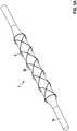
- Fig. 1Aschematically shows a balloon catheter stent device 1, which has a balloon catheter 3 with a catheter tube 3a and a balloon portion 3b and a stent surrounding the balloon portion 5, in the un-inflated or un-dilated initial state
- Fig. 1Bshows the dilated balloon catheter stent apparatus 1 'with inflated balloon portion 3b' and stent 5 'in an end condition as effected upon inflation into a vasculature by inflation of the balloon portion for the purpose of treating a stenosis.
- the stent 5 'has, in a known manner, a lattice structure which widens radially during dilation and is shortened axially.
- Fig. 2shows in a schematic perspective view of a folding unit 7, which is attached to two lattice elements 9a, 9b of a grid structure 9 of a stent, in a folded and thus a projection 10 on the remaining surface ("global peripheral surface") of the stent forming end state.
- This conditionis the same as in Fig. 1B shown dilated state of the stent 5 ', in which the peripheral surface forming lattice structure, although radially expanded, but is axially shortened.
- the axial shorteningeffects the folding and setting up of the folding mechanism 7 lying essentially flat in the peripheral surface in the initial state.
- Fig. 3shows, as a further embodiment, a folding mechanism 11, which in the end state shown here has the folding geometry of a simple tetrahedron, in turn fastened to two lattice elements 13a, 13b of a stent lattice structure and projects radially beyond the remainder of the surface of the stent lattice structure Projection 14 forms.
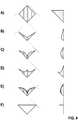
- Fig. 4schematically shows further geometric configurations a) to f) of folded structures in the erected end state, with projections (10 and 14) having different angles (FIG. Fig. 4a and Fig 4b ) or convex ( Fig. 4c ) and concavely curved ( Fig. 4d ) or with sawtooth geometry ( Fig. 4e ) Edges are formed.
- Fig. 4fshows a folding geometry from individual bar elements.
Landscapes
- Health & Medical Sciences (AREA)
- Life Sciences & Earth Sciences (AREA)
- Engineering & Computer Science (AREA)
- Biomedical Technology (AREA)
- Veterinary Medicine (AREA)
- Public Health (AREA)
- Heart & Thoracic Surgery (AREA)
- Vascular Medicine (AREA)
- Surgery (AREA)
- Animal Behavior & Ethology (AREA)
- General Health & Medical Sciences (AREA)
- Oral & Maxillofacial Surgery (AREA)
- Cardiology (AREA)
- Nuclear Medicine, Radiotherapy & Molecular Imaging (AREA)
- Transplantation (AREA)
- Medical Informatics (AREA)
- Molecular Biology (AREA)
- Orthopedic Medicine & Surgery (AREA)
- Media Introduction/Drainage Providing Device (AREA)
Abstract
Translated fromGerman
Description
Translated fromGermanDie Erfindung betrifft eine Ballonkatheter-Stent-Vorrichtung, welche einen Ballonkatheter, der einen Katheterschlauch und einen radial aufweitbaren Ballonabschnitt umfasst, und einen den Ballonabschnitt umgebenden Stent aufweist, der durch den und in seiner radialen Erstreckung im Wesentlichen korrespondierend zum Ballonabschnitt radial aufweitbar ist.The invention relates to a balloon catheter stent apparatus comprising a balloon catheter comprising a catheter tube and a radially expandable balloon portion and a stent surrounding the balloon portion which is radially expandable through and in its radial extent substantially corresponding to the balloon portion.
Derartige Vorrichtungen sind seit langem bekannt und hunderttausendfach im klinischen Einsatz zur Behandlung von Gefäßverengungen (Stenosen) von Blutgefäßen. Die seit langem bekannte Behandlung durch Aufweitung (Dilatation) mittels eines Ballonkatheters wird bei solchen Vorrichtungen ergänzt um eine Stabilisierung des aufgeweiteten Gefäßabschnitts mittels eines Stützelementes, das durch den mittels des Ballons aufgeweiteten und nach der Deflatation des Ballons und dem Zurückziehen des Ballonkatheters am Ort der Stenose zurückgelassenen Stent (Stenting). Zu derartigen Vorrichtungen wird rein beispielhaft auf die
In vielen Fällen ist zusätzlich zur Aufweitung und Stabilisierung des Stenose-Abschnitts ein mindestens partielles Aufbrechen von Ablagerungen auf der Gefäßwand wünschenswert. Zu diesem Zweck wurden Ballonkatheter mit sogenanntem Schneidballon (Cutting Balloons) mit Schneidklingen auf der Ballonoberfläche sowie neuerdings auch Stents mit Werkzeugelementen (Scoring Elements) zur Bearbeitung von Gefäßablagerungen entwickelt und auch bereits klinisch eingesetzt. Die
Es hat sich gezeigt, dass beide Lösungen erhebliche Nachteile haben.It has been shown that both solutions have significant disadvantages.
Schneidballone sind in Folge der aufgesetzten Schneidelemente relativ steif und können nur schwer in komplexe Läsionen eingeführt werden, und es besteht hier auch ein nennenswertes Perforationsrisiko. Über dies ist der minimale (deflatierte) Ballondurchmesser größer als bei vergleichbaren Ballonen ohne Schneidelemente. Schließlich leisten Schneidballone beim Vorschieben der Vorrichtung durch das Gefäßsystem einen relativ großen Widerstand, der die präzise Handhabung erschwert.Cutting balloons are relatively stiff due to the attached cutting elements and can be difficult to introduce into complex lesions, and there is also a significant risk of perforation here. Above this, the minimum (deflated) balloon diameter is larger than comparable balloons without cutting elements. Finally, cutting balloons afford a relatively large resistance when advancing the device through the vascular system, which makes precise handling difficult.
Bei Stents mit Scoring-Elementen besteht unter Anderem die Gefahr, dass die auch im Einführungs-Zustand abstehenden Scoring-Elemente an unerwünschten und unvorhergesehenen Stellen zu Gewebeschädigungen führen. Andererseits sind die am beabsichtigten Einsatzort bei klinischen Studien tatsächlich erzielten Wirkungen nicht zufriedenstellend.For stents with scoring elements, there is a risk that the scoring elements, which also stick out in the introductory state, lead to tissue damage at undesired and unforeseen points. On the other hand, the actual effects achieved at the intended site during clinical trials are unsatisfactory.
Der Erfindung liegt daher die Aufgabe zu Grunde, eine verbesserte Vorrichtung der genannten Art bereitzustellen, die zu einem Aufbrechen von Gefäßablagerungen im Zuge der Ballondilatation und Stent-Versorgung von Stenosen geeignet und leicht und sicher handhabbar ist.The invention is therefore based on the object to provide an improved device of the type mentioned, which is suitable for breaking up vessel deposits in the course of balloon dilatation and stent supply of stenoses and easy and safe to handle.
Diese Aufgabe wird durch eine Ballonkatheter-Stent-Vorrichtung mit den Merkmalen des Anspruchs 1 gelöst. Zweckmäßige Fortbildungen des Erfindungsgedankens sind Gegenstand der abhängigen Ansprüche.This object is achieved by a balloon catheter stent apparatus having the features of claim 1. Advantageous developments of the inventive concept are the subject of the dependent claims.
Die Erfindung schließt den Gedanken ein, die Vorrichtung mit mindestens einem Elemente, bevorzugt einer Vielzahl von Elementen, auszustatten, das sich im Ausgangszustand (deflatierten Zustand des Ballons) praktisch in die Oberfläche des Stents einfügt, jedoch im Gebrauchs- bzw. Endzustand (inflatierten Zustand des Ballons und dilatierten Zustand des Stents) aus der Oberfläche des Stents lokal hervorspringt und hierdurch eine Bearbeitungswirkung gegenüber den Stent im Gebrauchszustand umgebenden Materialschichten erzielen kann. Weiterhin schließt die Erfindung den Gedanken ein, diese nur im Gebrauchszustand vorhandenen Stent-Vorsprünge unter Nutzung der Verformung zu erzeugen, die der Stent bei der Dilatation erfährt. Schließlich gehört zur Erfindung der Gedanke, die Stent-Vorsprünge durch Faltwerke zu bilden, die sich im Ausgangs-Zustand im aufgefalteten bzw. ausgebreiteten Zustand befinden, und in die Oberfläche des Stents eingebettet sind während sie durch die Verkürzung des Stents bei seiner Aufweitung in den Falt-Zustand versetzt werden und sich somit über die globale End-Umfangsfläche des Stents hinaus lokal aufstellen.The invention includes the idea of equipping the device with at least one element, preferably a plurality of elements, which, in the initial state (deflated state of the balloon), practically fits into the surface of the stent but in the used state (inflated state) the balloon and dilated state of the stent) from the surface of the stent locally jumps out and thereby can achieve a processing action against the stent in use state surrounding material layers. Furthermore, the invention includes the idea of producing these stent protrusions, which are only in use, by utilizing the deformation experienced by the stent during dilatation. Finally, the invention includes the idea to form the stent projections by folding units, which unfolded in the initial state in or expanded state, and are embedded in the surface of the stent as they are translated by the shortening of the stent in its expansion in the folded state and thus set up beyond the global end peripheral surface of the stent locally.
Gemäß der Grundidee der Erfindung wird die Verkürzung des Stents, welche zwangsläufig mit der radialen Expansion durch die Inflation des Ballons erfolgt, für das Aufstellen der Faltwerke auszunutzen. Radial expandierbare Stents weisen in Umfangsrichtung eine irgendwie geartete Mäander- oder Zick-Zack- oder sonstige Wellenstruktur auf. Bei radialer Expansion werden diese Strukturen in Umfangsrichtung auseinander gezogen und gleichzeitig in axialer Richtung entsprechend gestaucht. Vereinfacht ausgedrückt vergrößert sich die Wellenlänge einer in Umfangsrichtung verlaufenden Struktur während sich ihre Amplitude verkleinert. Die in axialer Richtung verkürzend wirkenden Kräfte werden bei der vorliegenden Erfindung zum Falten und Aufstellen der Stent-Vorsprünge genutzt.According to the basic idea of the invention, the shortening of the stent, which inevitably takes place with the radial expansion due to the inflation of the balloon, is utilized for setting up the folding mechanisms. Radially expandable stents have in the circumferential direction of any kind of meandering or zig-zag or other wave structure. In radial expansion, these structures are pulled apart in the circumferential direction and simultaneously compressed in the axial direction accordingly. In simple terms, the wavelength of a circumferential structure increases as its amplitude decreases. The forces acting in the axial direction shortening forces are used in the present invention for folding and setting up the stent projections.
Mit der erfindungsgemäßen Lösung werden, zumindest in bevorzugten Ausführungen, unter anderem folgende Vorteile erzielt:
- Durch die Faltwerke wird eine große radiale Expansion erreicht. Das erlaubt einen sehr kleinen Querschnitt des Ballonkatheters. Somit können Stenosen erreicht werden, die sonst nicht oder nur mit einem mehrschrittigen Prozedur aufgeweitet werden können.
- Durch die Faltwerke und die Struktur ist das Aufstellen der Stent-Vorsprünge geführt und robust.
- Je nach Anwendungsfall (Aufbrechen von Stenosen oder Verankerung, von z. B. Herzklappen) sind flexible Ausführungen möglich.
- Vorteilhafter Transport und Zuführen des Implantats wegen kleinem Querschnitt und relativ ungestörter Oberfläche.
- The folding units achieve a large radial expansion. This allows a very small cross-section of the balloon catheter. Thus, stenoses can be achieved, which can not otherwise be expanded or only with a multi-step procedure.
- Due to the folding mechanisms and the structure, the placement of the stent projections is guided and robust.
- Depending on the application (rupture of stenoses or anchoring, eg of heart valves), flexible designs are possible.
- Advantageous transport and feeding of the implant because of small cross-section and relatively undisturbed surface.
Grundsätzlich ist die vorgeschlagene Lösung und die Erzielung der genannten Vorteile auch in einer reinen Stent-Vorrichtung (ohne Ballonkatheter) realisierbar. Dann wird die gleiche Stent-Struktur nicht mittels des Ballons des Ballonkatheters, sondern auf andere Weise dilatiert, und die Dilatation realisiert die gleichen Funktionen und hat die gleichen Wirkungen wie oben beschrieben. Aus derzeitiger Sicht ist die Vorrichtung mit Ballonkatheter jedoch bevorzugt, weil sie größere tangentiale bzw. radiale Kräfte bereitstellen kann und somit eine grundsätzlich robustere und zuverlässige Ausführung der Erfindung ermöglichen dürfte.In principle, the proposed solution and the achievement of the advantages mentioned also in a pure stent device (without balloon catheter) can be realized. Then, the same stent structure is not used by the balloon of the balloon catheter, but on others It dilates, and the dilatation performs the same functions and has the same effects as described above. However, from a current point of view, the balloon catheter device is preferred because it can provide greater tangential or radial forces and thus allow for a more robust and reliable embodiment of the invention.
In Ausführungen der Erfindung sind die Faltwerke derart ausgebildet, dass sie bei ihrer Faltung und Aufstellung Stent-Vorsprünge mit einer Höhe über der globalen End-Umfangsfläche des Stents ausbilden, die abhängig vom jeweiligen globalen End-Umfang des Stents ist. Dies ermöglicht gewissermaßen eine "selbsttätige" Einstellung der wirksamen Höhe der mit den Stent-Vorsprüngen geschaffenen Werkzeugabschnitte (bzw. Verankerungshilfen) an die Dimensionen des zu behandelnden Gefäßes bzw. der jeweiligen Läsion.In embodiments of the invention, the pleats are configured to form stent protrusions at a height above the global end peripheral surface of the stent when folded and deployed, which is dependent on the respective global end circumference of the stent. This effectively enables an "automatic" adjustment of the effective height of the tool sections (or anchoring aids) created with the stent projections to the dimensions of the vessel or the respective lesion to be treated.
In bevorzugten Ausführungen der Erfindung sind die Faltwerke derart ausgebildet, dass bei ihrer zunehmenden Faltung und Aufstellung eine axiale und eine radiale und/oder tangentiale Bewegungskomponente auftritt. Hierdurch lässt sich bereits im Vorgang der Inflation des Ballons und Dilatation des Stents eine Relativbewegung zur umgebenden Stenose und somit eine gewisse Bearbeitungs-Wirkung erzielen, ohne dass es hier zu einer gesonderten Bewegung des Ballonkatheters bedürfte.In preferred embodiments of the invention, the folding mechanisms are designed in such a way that an axial and a radial and / or tangential movement component occurs with their increasing folding and installation. As a result, a relative movement to the surrounding stenosis and thus a certain processing effect can be achieved already in the process of inflation of the balloon and dilation of the stent, without the need for a separate movement of the balloon catheter here.
In einer weiteren Ausführung der Erfindung sind die Faltwerke derart ausgebildet, dass sie im Ausgangszustand des Stents aufgefaltet in dessen globaler Ausgangs-Umfangsfläche liegen oder sich nicht mehr als 20%, bevozugt 1% bis 10%, des Ausgangs-Radius aus dieser erheben. Dies ermöglicht die im Hinblick auf ein möglichst leichtes und gefahrloses Einführen der Vorrichtung wünschenswerte "ungestörte" Oberflächenkontur des undilatierten Stents. Bevorzugt liegen die Faltwerke im Ausgangszustand des Stents (und auch im gecrimpten Zustand bei der Implantation) in der Ausgangs-Umfangsfläche, d.h. die Faltwerke erstrecken sich nicht radial über die restliche Strebenstruktur des Stents hinaus. Faltwerke, die sich aus der Ausgangs-Umfangsfläche hinaus erheben, kommen zweckmäßigerweise nur in speziellen Fällen zum Einsatz. In diesen speziellen Fällen erheben sich die Faltwerke vorteilhafterweise nicht mehr als 20%, bevorzugt zwischen 1% und 10%, des Ausgangs-Radius aus der Ausgangs-Umfangsfläche hinaus.In a further embodiment of the invention, the folding units are designed such that they are unfolded in the initial state of the stent in its global output peripheral surface or not more than 20%, preferably 1% to 10%, of the initial radius rise from this. This makes possible the "undisturbed" surface contour of the undilated stent, which is desirable in view of the easiest and safest possible introduction of the device. Preferably, in the initial state of the stent (and also in the crimped state during implantation), the folds lie in the starting peripheral surface, ie the folds do not extend radially beyond the remaining strut structure of the stent. Folds, which rise out of the output circumferential area, are expediently used only in special cases. In these special cases arise the folding units advantageously not more than 20%, preferably between 1% and 10%, of the initial radius from the starting peripheral surface.
Zweckmäßigerweise wird die Kombination aus dem Ballon und darauf befindlichen Stent mit Faltwerken auf einen Außendurchmesser zwischen 1.2 mm und 2.2 mm komprimiert, so dass die Kombination geeignet ist, über einen 4F bis 6F Zugang in den Körper eines Patienten eingeführt zu werden. Der Ballon und damit der Innendurchmesser des Stents mit Faltwerken kann vorteilhafterweise auf einen Durchmesser zwischen 2 mm und 10 mm expandiert werden. Die Faltwerke sorgen für eine Radiusvergrösserung von bis zu 1.7mm. Abhängig von Verhältnis zwischen komprimierten und expandierten Durchmesser des Stents verkürzt sich der Stent bei der Expansion um bis zu 15 mm. Bevorzugt sorgen die Faltwerke für eine Durchmesservergößerung im expandierten Zustand auf einen Wert zwischen 110% und 200%, bevorzugt zwischen 125% und 175% besonders bevorzugt zwischen 130% und 160% Hierbei entsprechen 100% dem Durchmesser des expandierten Stents ohne Faltwerke.Conveniently, the combination of balloon and folded stent thereon is compressed to an outside diameter of between 1.2mm and 2.2mm so that the combination is capable of being introduced into the body of a patient via a 4F to 6F access. The balloon and thus the inner diameter of the stent with folding units can be advantageously expanded to a diameter between 2 mm and 10 mm. The folding units provide a radius enlargement of up to 1.7mm. Depending on the ratio of compressed and expanded diameter of the stent, the stent is shortened by up to 15 mm during expansion. The folding units preferably provide for an increase in diameter in the expanded state to a value between 110% and 200%, preferably between 125% and 175%, particularly preferably between 130% and 160%. In this case, 100% corresponds to the diameter of the expanded stent without folding units.
Die axiale Verkürzung treibt wie bereits erläutert das radiale Aufstellen der Faltwerke. In einer alternativen Ausgestaltung der Erfindung kann die axiale Verkürzung für eine zusätzliche relative Bewegung der Faltwerke gegenüber der Gefäßwand genutzt werden. In dieser Ausgestaltung wird das Stentdesign so gewählt, dass mit der Expansion eine extreme axiale Verkürzung um nahezu 100% Prozent der Stentlänge einhergeht. Dadurch werden die Faltwerke bei Expansion nicht nur aufgestellt sondern verändern auch ihre axiale Position bezüglich des Katheters, d.h. die Faltwerke bewegen sich nach distal oder proximal in Bezug auf die Katheterachse und damit auch zur behandelnden Gefäßwand. In dieser Ausgestaltung kann somit ein aktives Aufbrechen, ähnlich einem Aufschneiden, der Stenose kommen.The axial shortening drives, as already explained, the radial erection of the folding units. In an alternative embodiment of the invention, the axial shortening can be used for additional relative movement of the folding units relative to the vessel wall. In this embodiment, the stent design is chosen so that the expansion is accompanied by an extreme axial shortening of almost 100% of the stent length. As a result, the folds are not only deployed upon expansion but also change their axial position relative to the catheter, i. The folds move distally or proximally with respect to the catheter axis and thus also to the treated vessel wall. In this embodiment, therefore, an active break, similar to a cutting, come to the stenosis.
In weiteren Ausführungen der Erfindung haben die Faltwerke im gefalteten und aufgestellten Zustand im Wesentlichen eine Pyramiden- oder überlagerte Tetraeder-Form. Grundsätzlich sind vielgestaltige andere Ausführungen der Faltwerke möglich, sofern deren Aufbau nicht zu kompliziert und die gezielte Faltung unter Einsatzbedingungen zuverlässig sichergestellt ist. Die Wahl einer konkreten Geometrie wird sich auch nach dem Einsatzgebiet und der vorranging beabsichtigten Funktion der Stent-Vorsprünge (etwa Aufsprengen oder Abtragen von Stenosen oder Verankerung des Stents) richten.In further embodiments of the invention, the folded structures in the folded and erected state essentially have a pyramidal or superimposed tetrahedral shape. In principle, many different designs of the folding units are possible, provided that their construction is not too complicated and the targeted folding under conditions of use is reliably ensured. The choice of a concrete geometry will also change according to the field of application and the intended function of the stent projections (such as bursting or ablating stenoses or anchoring the stent).
In weiteren Ausführungen weist der Stent eine reguläre Gitterstruktur aus Gitterstabelementen auf, und die Faltwerke sind mindestens teilweise von Gitterstabelementen gebildet oder an diese fest angefügt. Stents, die aus regulären Gitterstrukturen gebildet sind, sind in vielgestaltigen Ausführungen bekannt und bewährt, und ihre Herstellung ist technologisch ausgereift und kostengünstig. Die genannte Ausführung der Erfindung kann auf diesen Vorteilen aufbauen und somit gleichfalls zu besonders zuverlässigen und kostengünstigen Produkten führen.In further embodiments, the stent has a regular lattice structure of lattice-rod elements, and the creases are at least partially formed by or fixedly attached to lattice-rod elements. Stents formed from regular grid structures are well known and proven in many designs, and their manufacture is technologically mature and cost effective. Said embodiment of the invention can build on these advantages and thus also lead to particularly reliable and cost-effective products.
Im Übrigen können die Faltwerke integral mit der übrigen Struktur des Stents und insbesondere mittels des gleichen Formgebungsverfahrens wie jene gebildet sein, etwa durch im Wesentlichen einstufiges Laserschneiden der Gesamtstruktur aus einem rohrförmigen Halbzeug. Alternativ können die Faltwerke aus einem anderen Material als die übrige Struktur des Stents gebildet und in einem gesonderten Anfügungs-Schritt an jene angefügt sein. Letztere Varianten ermöglichen eine besonders differenzierte Ausführung der Faltwerke, bei gleichzeitiger Nutzung einer bewährten Stent-Grundstruktur.Incidentally, the folding mechanisms may be formed integrally with the remainder of the structure of the stent, and in particular by means of the same molding process as that, such as by essentially one-step laser cutting of the overall structure from a tubular semi-finished product. Alternatively, the folds may be formed of a different material than the remainder of the structure of the stent and attached to them in a separate attachment step. The latter variants allow a particularly differentiated design of the folding units, while using a proven stent basic structure.
In weiteren Ausführungen ist vorgesehen, dass Endabschnitte bzw. -punkte von Faltkanten der Faltwerke mit Querschnittsverjüngungen oder Perforationen als Soll-Biegestellen oder einem Formgedächtnis-Material gebildet sind. Der Ort, wo die Faltwerke gefaltet werden kann also vorgängig bestimmt werden durch Materialschwächungen oder durch Einprägung der Form (z. B. bei Nitinol). Durch entsprechende Verjüngungen und/oder durch den unter dem Faltwerk liegenden Ballon wird sichergestellt, dass sich das Faltwerk nach außen ausbreitet.In further embodiments, it is provided that end sections or points of folding edges of the folding units are formed with cross-sectional tapers or perforations as desired bending points or a shape memory material. The place where the folding units can be folded can thus be determined beforehand by weakening the material or by imprinting the form (eg Nitinol). By appropriate rejuvenation and / or by the underlying balloon under the folding ensures that the folding mechanism propagates to the outside.
In aus derzeitiger Sicht bevorzugten Ausführungen, die direkt dem zu Grunde liegenden Problem gewidmet sind, weist mindestens ein Teil der Faltwerke jeweils mindestens eine Schneid- oder Sägekante zum schneidenden oder sägenden Eingriff in ein äußeres Material, insbesondere eine Stenose eines Blutgefäßes, auf. Die Funktion des durch die eine oder mehreren Schneid- oder Sägekante/n gebildeten Werkzeugs lässt sich durch die Geometrie des zu Grunde liegenden Faltwerks und die selektive Platzierung der jeweiligen Bearbeitungskante/n in weiten Grenzen variieren.In presently preferred embodiments, which are directly devoted to the underlying problem, at least a part of the folding units each have at least one cutting or sawing edge for cutting or sawing engagement in an outer material, in particular a stenosis of a blood vessel. The function of the tool formed by the one or more cutting or sawing edge (s) can be determined by the geometry of the underlying folding work and the selective placement of the respective processing edge / s vary within wide limits.
In anderen Ausführungen weist mindestens ein Teil der Faltwerke jeweils mindestens eine gebogene, insbesondere konkav gekrümmte, Fixierungskante zum Eingriff in eine äußere Struktur, insbesondere die Wandung eines Blutgefäßes oder Organs, auf.In other embodiments, at least a part of the folding units each have at least one curved, in particular concavely curved, fixing edge for engagement in an outer structure, in particular the wall of a blood vessel or organ.
In weiteren Ausführungen sind auf der Umfangsfläche des Stents mindestens in Zwischenbereichen zwischen einigen Faltwerken elastisch (oder ggfs. auch plastisch) verformbare Ausgleichsbereiche zur Verringerung der resultierenden Verkürzung des Stents vorgesehen. Je nach Anordnung können solche Federelemente auch eine Relativbewegung der Faltwerke zur Stenose bewirken, was für das Schneiden der Verkalkung von Vorteil wäre.In further embodiments, elastically (or optionally also plastically) deformable compensation areas are provided on the circumferential surface of the stent, at least in intermediate areas between some folding units, in order to reduce the resulting shortening of the stent. Depending on the arrangement, such spring elements can also cause a relative movement of the folding units to the stenosis, which would be advantageous for cutting the calcification.
Die Faltwerke können auch Grundelemente sein, wo andere Komponenten angebracht sind z. B. ein Stab, der mit mehreren Faltwerken verbunden ist.The folding units can also be basic elements where other components are attached z. B. a rod which is connected to several folding units.
Die Stentstruktur kann lose auf dem Ballon liegen, fest mit ihm verbunden oder aber auch fest/lose mit dem Ballonhals oder Schlauch verbunden sein.The stent structure can be loose on the balloon, firmly connected to it or else firmly / loosely connected to the balloon neck or tube.
Im Falle eines Implantats, das durch die Faltwerke besser verankert werden soll, ist eine lose Verbindung zum Ballon/Schlauch zweckmäßig.
Für den bevorzugten Anwendungsfall des Aufbrechens eine Stenose, bei der die Scoring Elemente wieder rausgeführt werden müssen, ist eine zumindest teilweise feste Verbindung zum Ballon/Schlauch nötig.In the case of an implant, which is to be better anchored by the folding units, a loose connection to the balloon / hose is appropriate.
For the preferred application of breaking a stenosis in which the scoring elements must be led out again, an at least partially solid connection to the balloon / hose is necessary.
Als Scoring-Vorrichtung ist es von Vorteil, wenn die Stentstruktur aus einem Formgedächtnis-Material (z. B. Nitinol) ist, damit sie sich nach erfolgtem Aufbrechen der Verkalkung wieder auf den ursprünglichen Querschnitt zurückzieht. Die im Formgedächtnis-Material eingeprägte Form der Stentstruktur ist dabei die ursprüngliche Form, wo die Faltwerke nicht aufgestellt sind. Die Kraft für das Aufstellen der Faltwerke kommt in diesem Fall von der Inflation eines Ballons. Wenn der Ballon deflatiert wird, geht die Stentstruktur von sich aus wieder in die eingeprägte Form zurück . Die Faltwerke falten sich somit wieder ein.As a scoring device, it is advantageous if the stent structure is of a shape memory material (eg Nitinol), so that it retracts to the original cross-section after the calcification has broken up. The impressed shape memory material form of the stent structure is the original form, where the folding units are not placed. The force for setting up the folding units in this case comes from the inflation of a balloon. When the balloon is deflated, the stent structure goes by itself back to the embossed form. The folding units thus fold in again.
Andere Materialen sind aber auch denkbar, vor allem wenn die Struktur zur Verankerung dient. In diesem Fall ist eine Zurückfalten der Faltwerke nicht nötig. Aber auch beim Aufbrechen einer Stenose kommen Materialien für Stent und Faltwerke in Frage, die keine Formgedächtniseigenschaften aufweisen. In diesem Fall werden die Materialien plastisch durch die Inflation des Ballons verformt (die Faltwerke werden aufgerichtet) und durch die Kraft des deflatierenden Ballons wieder plastisch zurück verformt (die Faltwerke gehen wieder in den komprimierten Ausgangszustand zurück). In dieser Ausgestaltung der Verbindung sind Ballon und Stent fest verbunden, bevorzugt über die gesamte Auflagefläche des Stents.Other materials are also conceivable, especially if the structure is used for anchoring. In this case it is not necessary to fold back the folding units. But even when a stenosis is ruptured, materials for stent and folded structures are possible which have no shape memory properties. In this case, the materials are plastically deformed by the inflation of the balloon (the pleats are erected) and plastically deformed back by the force of the deflating balloon (the pleats return to the compressed initial state). In this embodiment of the compound balloon and stent are firmly connected, preferably over the entire bearing surface of the stent.
Vorteile und Zweckmäßigkeiten der Erfindung ergeben sich im Übrigen aus der nachfolgenden Beschreibung eines Ausführungsbeispiels anhand der Figuren. Von diesen zeigen:
- Fig. 1A und 1B
- skizzenartige perspektivische Darstellungen des Grundaufbaus einer Ballonkatheter-Stent-Vorrichtung im Ausgangs-Zustand bzw. im dilatierten End-Zustand,
- Fig. 2
- eine schematische Darstellung des Faltwerks einer Ausführungsform der erfindungsgemäßen Ballonkathether-Stent-Vorrichtung,
- Fig. 3
- eine schematische Darstellung des Faltwerks einer Ausführungsform der erfindungsgemäßen Ballonkathether-Stent-Vorrichtung, und
- Fig. 4
- eine schematische Zusammenstellung von Grund-Geometrien von Faltwerken erfindungsgemäßer Ballonkatheter-Stent-Vorrichtungen, jeweils in Draufsicht (links) und Seitenansicht (rechts) im dilatierten Zustand des Stents.
- Fig. 1A and 1B
- sketch-like perspective views of the basic structure of a balloon catheter stent device in the initial state or in the dilated end state,
- Fig. 2
- a schematic representation of the folding mechanism of an embodiment of the balloon catheter stent device according to the invention,
- Fig. 3
- a schematic representation of the folding mechanism of an embodiment of the balloon catheter stent device according to the invention, and
- Fig. 4
- a schematic combination of basic geometries of folding devices according to the invention balloon catheter stent devices, respectively in plan view (left) and side view (right) in the dilated state of the stent.
Im Übrigen ist die Ausführung der Erfindung auch in einer Vielzahl von Abwandlungen der hier gezeigten Beispiele und weiter oben hervorgehobenen Aspekte der Erfindung möglich.Incidentally, the embodiment of the invention is also possible in a variety of modifications of the examples shown here and aspects of the invention highlighted above.
Claims (14)
Translated fromGermanPriority Applications (5)
| Application Number | Priority Date | Filing Date | Title |
|---|---|---|---|
| EP17196977.7AEP3473214A1 (en) | 2017-10-18 | 2017-10-18 | Balloon catheter-stent device |
| US16/649,924US11730617B2 (en) | 2017-10-18 | 2018-09-17 | Balloon catheter stent device with stent protrusions |
| PCT/EP2018/075041WO2019076557A1 (en) | 2017-10-18 | 2018-09-17 | Balloon catheter stent device |
| EP18782646.6AEP3697351A1 (en) | 2017-10-18 | 2018-09-17 | Balloon catheter stent device |
| CN201880065516.0ACN111194195A (en) | 2017-10-18 | 2018-09-17 | Balloon catheter-stent device |
Applications Claiming Priority (1)
| Application Number | Priority Date | Filing Date | Title |
|---|---|---|---|
| EP17196977.7AEP3473214A1 (en) | 2017-10-18 | 2017-10-18 | Balloon catheter-stent device |
Publications (1)
| Publication Number | Publication Date |
|---|---|
| EP3473214A1true EP3473214A1 (en) | 2019-04-24 |
Family
ID=60153096
Family Applications (2)
| Application Number | Title | Priority Date | Filing Date |
|---|---|---|---|
| EP17196977.7AWithdrawnEP3473214A1 (en) | 2017-10-18 | 2017-10-18 | Balloon catheter-stent device |
| EP18782646.6APendingEP3697351A1 (en) | 2017-10-18 | 2018-09-17 | Balloon catheter stent device |
Family Applications After (1)
| Application Number | Title | Priority Date | Filing Date |
|---|---|---|---|
| EP18782646.6APendingEP3697351A1 (en) | 2017-10-18 | 2018-09-17 | Balloon catheter stent device |
Country Status (4)
| Country | Link |
|---|---|
| US (1) | US11730617B2 (en) |
| EP (2) | EP3473214A1 (en) |
| CN (1) | CN111194195A (en) |
| WO (1) | WO2019076557A1 (en) |
Families Citing this family (3)
| Publication number | Priority date | Publication date | Assignee | Title |
|---|---|---|---|---|
| CN113561490A (en)* | 2021-07-01 | 2021-10-29 | 浙江大学 | An intelligent construction method of 4D printing folding space structure |
| CN116271455B (en)* | 2023-05-22 | 2023-08-01 | 杭州亿科医疗科技有限公司 | Force-gathering expansion saccule for directional breaking vascular calcification lesion |
| CN116271457B (en)* | 2023-05-23 | 2023-08-04 | 杭州亿科医疗科技有限公司 | Force-gathering expansion balloon and force-gathering expansion balloon system |
Citations (7)
| Publication number | Priority date | Publication date | Assignee | Title |
|---|---|---|---|---|
| US5855597A (en)* | 1997-05-07 | 1999-01-05 | Iowa-India Investments Co. Limited | Stent valve and stent graft for percutaneous surgery |
| US20020010489A1 (en)* | 2000-07-24 | 2002-01-24 | Jeffrey Grayzel | Stiffened balloon catheter for dilatation and stenting |
| US20030220683A1 (en)* | 2002-05-22 | 2003-11-27 | Zarouhi Minasian | Endoluminal device having barb assembly and method of using same |
| DE102004059523A1 (en) | 2003-12-09 | 2005-07-21 | Laboratoires Perouse - French Corp. - | Device for treating blood vessels and method for preparing this device |
| WO2009046206A1 (en) | 2007-10-05 | 2009-04-09 | Angioscore, Inc. | Scoring catheter with drug delivery membrane |
| US8348987B2 (en) | 2009-12-22 | 2013-01-08 | Cook Medical Technologies Llc | Balloon with scoring member |
| US20140277562A1 (en)* | 2013-03-13 | 2014-09-18 | Boston Scientific Scimed, Inc. | Anti-Migration Tissue Anchoring System for a Fully Covered Stent |
Family Cites Families (8)
| Publication number | Priority date | Publication date | Assignee | Title |
|---|---|---|---|---|
| US5397355A (en)* | 1994-07-19 | 1995-03-14 | Stentco, Inc. | Intraluminal stent |
| CA2163708C (en)* | 1994-12-07 | 2007-08-07 | Robert E. Fischell | Integrated dual-function catheter system for balloon angioplasty and stent delivery |
| US5591197A (en)* | 1995-03-14 | 1997-01-07 | Advanced Cardiovascular Systems, Inc. | Expandable stent forming projecting barbs and method for deploying |
| US6464718B1 (en)* | 1998-11-16 | 2002-10-15 | Cordis Corporation | Balloon catheter for stent delivery having microchannels and method |
| WO2003032871A1 (en)* | 2001-10-16 | 2003-04-24 | Massachusetts Institute Of Technology | Stent concept for minimization of deployment related wall shear and injury |
| US8323325B2 (en)* | 2006-09-25 | 2012-12-04 | Boston Scientific Scimed, Inc. | Balloon with wings for rotational stent |
| US8647376B2 (en)* | 2007-03-30 | 2014-02-11 | Boston Scientific Scimed, Inc. | Balloon fold design for deployment of bifurcated stent petal architecture |
| US9724121B2 (en)* | 2014-02-02 | 2017-08-08 | TriReme Medical, LLC | Apparatus and methods for recannalization, valve repair and replacement |
- 2017
- 2017-10-18EPEP17196977.7Apatent/EP3473214A1/ennot_activeWithdrawn
- 2018
- 2018-09-17EPEP18782646.6Apatent/EP3697351A1/enactivePending
- 2018-09-17USUS16/649,924patent/US11730617B2/enactiveActive
- 2018-09-17CNCN201880065516.0Apatent/CN111194195A/enactivePending
- 2018-09-17WOPCT/EP2018/075041patent/WO2019076557A1/ennot_activeCeased
Patent Citations (7)
| Publication number | Priority date | Publication date | Assignee | Title |
|---|---|---|---|---|
| US5855597A (en)* | 1997-05-07 | 1999-01-05 | Iowa-India Investments Co. Limited | Stent valve and stent graft for percutaneous surgery |
| US20020010489A1 (en)* | 2000-07-24 | 2002-01-24 | Jeffrey Grayzel | Stiffened balloon catheter for dilatation and stenting |
| US20030220683A1 (en)* | 2002-05-22 | 2003-11-27 | Zarouhi Minasian | Endoluminal device having barb assembly and method of using same |
| DE102004059523A1 (en) | 2003-12-09 | 2005-07-21 | Laboratoires Perouse - French Corp. - | Device for treating blood vessels and method for preparing this device |
| WO2009046206A1 (en) | 2007-10-05 | 2009-04-09 | Angioscore, Inc. | Scoring catheter with drug delivery membrane |
| US8348987B2 (en) | 2009-12-22 | 2013-01-08 | Cook Medical Technologies Llc | Balloon with scoring member |
| US20140277562A1 (en)* | 2013-03-13 | 2014-09-18 | Boston Scientific Scimed, Inc. | Anti-Migration Tissue Anchoring System for a Fully Covered Stent |
Also Published As
| Publication number | Publication date |
|---|---|
| EP3697351A1 (en) | 2020-08-26 |
| US20200276039A1 (en) | 2020-09-03 |
| US11730617B2 (en) | 2023-08-22 |
| CN111194195A (en) | 2020-05-22 |
| WO2019076557A1 (en) | 2019-04-25 |
Similar Documents
| Publication | Publication Date | Title |
|---|---|---|
| DE69926219T2 (en) | STENT WITH VARIABLE PROPERTIES | |
| DE60213516T2 (en) | Intravascular stent device | |
| DE69737208T2 (en) | STENT MOUNTING DEVICE WITH A SEPARATE SHEATH | |
| DE69928915T2 (en) | EXPANDABLE UNIT CELL AND INTRALUMINARY STENT | |
| DE69527636T2 (en) | STENT AND METHOD FOR THE PRODUCTION THEREOF | |
| DE602004010347T2 (en) | Stent with independent segments that can be uncoupled during expansion | |
| DE69634791T2 (en) | Stent with multiple anchoring | |
| DE10334868B4 (en) | Implantable device as a replacement organ valve, its manufacturing process and basic body and membrane element for it | |
| EP2450010B1 (en) | Balloon catheter, in particular for delivering drugs or stents in the region of a stenosis | |
| EP3209248B1 (en) | Stent for splinting a vein, and system for putting in place a stent | |
| DE60010517T2 (en) | EMBOLISM PROTECTIONS | |
| DE60021040T2 (en) | Flexible medical stent | |
| DE69829494T2 (en) | SUBSEQUENT INTRALUMINAL STENTS | |
| EP1200018B1 (en) | Insertion catheter for vascular prostheses | |
| DE69938232T2 (en) | EXPANDABLE STENT | |
| DE60207692T2 (en) | RÖNTGENOPAKES INTRALUMINAL MEDICAL DEVICE | |
| DE69915895T2 (en) | Intravascular stent with improved strut geometry | |
| DE10297483B4 (en) | System for applying a fastener to a prosthesis | |
| DE69410072T2 (en) | Expandable stents | |
| EP1667608B1 (en) | Stent comprising terminal anchoring elements | |
| DE69919811T2 (en) | Balloon catheter with microchannels for introducing a stent and associated method | |
| DE10253633B4 (en) | supporting structure | |
| EP3260084A1 (en) | Delivery catheter and catheter arrangement | |
| DE10153340A1 (en) | Stent for holding open blood vessel formed of intertwined meander patterns with series of triangular cells, has circumferential loop section, further loop section, and third loop section | |
| EP3213717A1 (en) | Delivery catheter and catheter arrangement |
Legal Events
| Date | Code | Title | Description |
|---|---|---|---|
| PUAI | Public reference made under article 153(3) epc to a published international application that has entered the european phase | Free format text:ORIGINAL CODE: 0009012 | |
| AK | Designated contracting states | Kind code of ref document:A1 Designated state(s):AL AT BE BG CH CY CZ DE DK EE ES FI FR GB GR HR HU IE IS IT LI LT LU LV MC MK MT NL NO PL PT RO RS SE SI SK SM TR | |
| AX | Request for extension of the european patent | Extension state:BA ME | |
| STAA | Information on the status of an ep patent application or granted ep patent | Free format text:STATUS: THE APPLICATION IS DEEMED TO BE WITHDRAWN | |
| 18D | Application deemed to be withdrawn | Effective date:20191025 |