EP3473175B1 - Ecg electrode connector - Google Patents
Ecg electrode connectorDownload PDFInfo
- Publication number
- EP3473175B1 EP3473175B1EP18193825.9AEP18193825AEP3473175B1EP 3473175 B1EP3473175 B1EP 3473175B1EP 18193825 AEP18193825 AEP 18193825AEP 3473175 B1EP3473175 B1EP 3473175B1
- Authority
- EP
- European Patent Office
- Prior art keywords
- lead wire
- pivoting lever
- wire connector
- housing
- ecg lead
- Prior art date
- Legal status (The legal status is an assumption and is not a legal conclusion. Google has not performed a legal analysis and makes no representation as to the accuracy of the status listed.)
- Active
Links
Images


Classifications
- A—HUMAN NECESSITIES
- A61—MEDICAL OR VETERINARY SCIENCE; HYGIENE
- A61B—DIAGNOSIS; SURGERY; IDENTIFICATION
- A61B5/00—Measuring for diagnostic purposes; Identification of persons
- A61B5/24—Detecting, measuring or recording bioelectric or biomagnetic signals of the body or parts thereof
- A61B5/25—Bioelectric electrodes therefor
- A61B5/271—Arrangements of electrodes with cords, cables or leads, e.g. single leads or patient cord assemblies
- A61B5/273—Connection of cords, cables or leads to electrodes
- A61B5/274—Connection of cords, cables or leads to electrodes using snap or button fasteners
- A—HUMAN NECESSITIES
- A61—MEDICAL OR VETERINARY SCIENCE; HYGIENE
- A61B—DIAGNOSIS; SURGERY; IDENTIFICATION
- A61B5/00—Measuring for diagnostic purposes; Identification of persons
- A61B5/24—Detecting, measuring or recording bioelectric or biomagnetic signals of the body or parts thereof
- A61B5/25—Bioelectric electrodes therefor
- A61B5/279—Bioelectric electrodes therefor specially adapted for particular uses
- A61B5/28—Bioelectric electrodes therefor specially adapted for particular uses for electrocardiography [ECG]
- A—HUMAN NECESSITIES
- A61—MEDICAL OR VETERINARY SCIENCE; HYGIENE
- A61B—DIAGNOSIS; SURGERY; IDENTIFICATION
- A61B5/00—Measuring for diagnostic purposes; Identification of persons
- A61B5/24—Detecting, measuring or recording bioelectric or biomagnetic signals of the body or parts thereof
- A61B5/30—Input circuits therefor
- A61B5/303—Patient cord assembly, e.g. cable harness
- H—ELECTRICITY
- H01—ELECTRIC ELEMENTS
- H01R—ELECTRICALLY-CONDUCTIVE CONNECTIONS; STRUCTURAL ASSOCIATIONS OF A PLURALITY OF MUTUALLY-INSULATED ELECTRICAL CONNECTING ELEMENTS; COUPLING DEVICES; CURRENT COLLECTORS
- H01R13/00—Details of coupling devices of the kinds covered by groups H01R12/70 or H01R24/00 - H01R33/00
- H01R13/02—Contact members
- H01R13/193—Means for increasing contact pressure at the end of engagement of coupling part, e.g. zero insertion force or no friction
- H—ELECTRICITY
- H01—ELECTRIC ELEMENTS
- H01R—ELECTRICALLY-CONDUCTIVE CONNECTIONS; STRUCTURAL ASSOCIATIONS OF A PLURALITY OF MUTUALLY-INSULATED ELECTRICAL CONNECTING ELEMENTS; COUPLING DEVICES; CURRENT COLLECTORS
- H01R13/00—Details of coupling devices of the kinds covered by groups H01R12/70 or H01R24/00 - H01R33/00
- H01R13/62—Means for facilitating engagement or disengagement of coupling parts or for holding them in engagement
- H01R13/627—Snap or like fastening
- H01R13/6277—Snap or like fastening comprising annular latching means, e.g. ring snapping in an annular groove
- H—ELECTRICITY
- H01—ELECTRIC ELEMENTS
- H01R—ELECTRICALLY-CONDUCTIVE CONNECTIONS; STRUCTURAL ASSOCIATIONS OF A PLURALITY OF MUTUALLY-INSULATED ELECTRICAL CONNECTING ELEMENTS; COUPLING DEVICES; CURRENT COLLECTORS
- H01R13/00—Details of coupling devices of the kinds covered by groups H01R12/70 or H01R24/00 - H01R33/00
- H01R13/62—Means for facilitating engagement or disengagement of coupling parts or for holding them in engagement
- H01R13/629—Additional means for facilitating engagement or disengagement of coupling parts, e.g. aligning or guiding means, levers, gas pressure electrical locking indicators, manufacturing tolerances
- H01R13/62933—Comprising exclusively pivoting lever
- H—ELECTRICITY
- H01—ELECTRIC ELEMENTS
- H01R—ELECTRICALLY-CONDUCTIVE CONNECTIONS; STRUCTURAL ASSOCIATIONS OF A PLURALITY OF MUTUALLY-INSULATED ELECTRICAL CONNECTING ELEMENTS; COUPLING DEVICES; CURRENT COLLECTORS
- H01R13/00—Details of coupling devices of the kinds covered by groups H01R12/70 or H01R24/00 - H01R33/00
- H01R13/62—Means for facilitating engagement or disengagement of coupling parts or for holding them in engagement
- H01R13/639—Additional means for holding or locking coupling parts together, after engagement, e.g. separate keylock, retainer strap
- A—HUMAN NECESSITIES
- A61—MEDICAL OR VETERINARY SCIENCE; HYGIENE
- A61B—DIAGNOSIS; SURGERY; IDENTIFICATION
- A61B2562/00—Details of sensors; Constructional details of sensor housings or probes; Accessories for sensors
- A61B2562/22—Arrangements of medical sensors with cables or leads; Connectors or couplings specifically adapted for medical sensors
- A61B2562/225—Connectors or couplings
- A61B2562/227—Sensors with electrical connectors
- H—ELECTRICITY
- H01—ELECTRIC ELEMENTS
- H01R—ELECTRICALLY-CONDUCTIVE CONNECTIONS; STRUCTURAL ASSOCIATIONS OF A PLURALITY OF MUTUALLY-INSULATED ELECTRICAL CONNECTING ELEMENTS; COUPLING DEVICES; CURRENT COLLECTORS
- H01R2101/00—One pole
- H—ELECTRICITY
- H01—ELECTRIC ELEMENTS
- H01R—ELECTRICALLY-CONDUCTIVE CONNECTIONS; STRUCTURAL ASSOCIATIONS OF A PLURALITY OF MUTUALLY-INSULATED ELECTRICAL CONNECTING ELEMENTS; COUPLING DEVICES; CURRENT COLLECTORS
- H01R2201/00—Connectors or connections adapted for particular applications
- H01R2201/12—Connectors or connections adapted for particular applications for medicine and surgery
- H—ELECTRICITY
- H01—ELECTRIC ELEMENTS
- H01R—ELECTRICALLY-CONDUCTIVE CONNECTIONS; STRUCTURAL ASSOCIATIONS OF A PLURALITY OF MUTUALLY-INSULATED ELECTRICAL CONNECTING ELEMENTS; COUPLING DEVICES; CURRENT COLLECTORS
- H01R24/00—Two-part coupling devices, or either of their cooperating parts, characterised by their overall structure
- H01R24/20—Coupling parts carrying sockets, clips or analogous contacts and secured only to wire or cable
- Y—GENERAL TAGGING OF NEW TECHNOLOGICAL DEVELOPMENTS; GENERAL TAGGING OF CROSS-SECTIONAL TECHNOLOGIES SPANNING OVER SEVERAL SECTIONS OF THE IPC; TECHNICAL SUBJECTS COVERED BY FORMER USPC CROSS-REFERENCE ART COLLECTIONS [XRACs] AND DIGESTS
- Y10—TECHNICAL SUBJECTS COVERED BY FORMER USPC
- Y10S—TECHNICAL SUBJECTS COVERED BY FORMER USPC CROSS-REFERENCE ART COLLECTIONS [XRACs] AND DIGESTS
- Y10S439/00—Electrical connectors
- Y10S439/909—Medical use or attached to human body
Definitions
- the present disclosurerelates to biomedical electrodes, and in particular, to a biomedical electrode connector for attaching a lead wire to an electrocardiogram (ECG) electrode placed on a patient's body.
- ECGelectrocardiogram
- Electrocardiograph (ECG) monitorsare widely used to obtain medical (i.e. biopotential) signals containing information indicative of the electrical activity associated with the heart and pulmonary system.
- ECG electrodesare applied to the skin of a patient in various locations.
- the electrodesafter being positioned on the patient, connect to an ECG monitor by a set of ECG lead wires.
- the distal end of the ECG lead wire, or portion closest to the patient,may include a connector which is adapted to operably connect to the electrode to receive medical signals from the body.
- the proximal end of the ECG lead setis operably coupled to the ECG monitor and supplies the medical signals received from the body to the ECG monitor.
- a typical ECG electrode assemblymay include an electrically conductive layer and a backing layer, the assembly having a patient contact side and a connector side.
- the contact side of the electrode padmay include biocompatible conductive gel or adhesive for affixing the electrode to a patient's body for facilitating an appropriate electrical connection between a patient's body and the electrode assembly.
- the connector side of the padmay incorporate a metallic press stud having a bulbous profile for coupling the electrode pad to the ECG lead wire.
- the clinicianremoves a protective covering from the electrode side to expose the gel or adhesive, affixes the electrode pad to the patient's body, and attaches the appropriate ECG lead wire connector to the press stud by pressing or "snapping" the lead wire connector onto the bulbous press stud to achieve mechanical and electrical coupling of the electrode and lead wire.
- a clinicianthen removes the ECG lead wire connector from the pad by pulling or "unsnapping" the connector from the pad.
- the described ECG lead wire connectormay have drawbacks.
- a clinicianmust apply considerable downward force on the lead wire connector to achieve positive engagement of the connector to the press stud.
- This high connecting forcemay cause additional and unnecessary discomfort or pain to the patient, whose existing medical condition may already be a source of discomfort or pain.
- a patient's discomfortmay be compounded by the need to connect multiple electrodes which are customarily employed during ECG procedures.
- a clinicianUpon completion of the ECG procedure, a clinician must unsnap the ECG lead wire connector from the pad, which may further cause discomfort to the patient. In some instances, the connector does not readily disengage from the press stud thus requiring the clinician to use considerable upward force to unseat the connector. Often, these attempts to decouple the ECG lead wire connector from the electrode press stud will instead cause the pad to be suddenly and painfully torn from the patient's skin. In other instances, attempts to detach the ECG lead wire will cause the pad to become partially dislodged from the patient, which may impair the electrode's ability to receive biopotential signals. This is undesirable when, for example, the clinician wishes to detach the lead wires temporarily yet wishes to leave the pads in place to perform ECG testing on the patient at a future time.
- a snap lock connectormay engage the press stud with insufficient force, which may cause suboptimal signal transmission from the electrode to the lead wire, as well as allowing the connector to be disengaged inadvertently by, for example, a slight tug on the lead wire.
- an embodiment of an ECG electrode connector 100 having a thumb cam lever 110The connector 100 includes a housing 105 that includes a cavity 106, a pivot pin 115, and a thumb cam lever 110 having a pivot hole 116 defined therein dimensioned to pivotably couple thumb cam lever 110 to pivot pin 115.
- Connector 100may also include a cover 305 which optionally includes an identification marking 310 which may be incorporated with cover 305 by any suitable means, including without limitation printing, engraving, silk screening, stamping, or integrally molding said marking 310 onto cover 305.
- the housing 105, lever 110 and cover 305may be constructed of any suitable non-conductive material, including without limitation any thermoplastic and/or elastomeric polymer such as polybutylene terephthalate (PBT), polyethylene terephthalate (PET), polyvinyl chloride (PVC), acrylonitrile butadiene styrene (ABS), thermoplastic polyurethanes (TPU), thermoplastic vulcanates (TPV), polypropylene (PP), polyethylene (PE), and/or fiber-reinforced polymer (FRP).
- PBTpolybutylene terephthalate
- PETpolyethylene terephthalate
- PVCpolyvinyl chloride
- ABSacrylonitrile butadiene styrene
- TPUthermoplastic polyurethanes
- TPVthermoplastic vulcanates
- PPpolypropylene
- PEpolyethylene
- FRPfiber-reinforced polymer
- a V-spring 120 having a coil base 130, a fixed leg 131 and a movable leg 132is coupled to housing 110 within cavity 106.
- Coil base 130 of V-spring 120may be multi-turn, single-turn, or a V-shaped apex without a coil.
- V-spring 120is retained at its base by pin 117 and is joined to housing 105 at its fixed end by saddle 125 such that movable leg 132 is biased in a distal direction, i.e., towards pivot pin 115. Additionally or alternatively, V-spring 120 may be joined to saddle 125 or cavity 106 by any suitable manner of bonding, such as by adhesive or heat welding.
- a stop 135limits the outward flexure of movable leg 132.
- Thumb cam lever 110includes a cam 102 which communicates with a detent 140 of spring member 120 when thumb cam lever 120 moves to a closed position, as shown in Fig. 2 .
- Detent 140 and cam 102cooperate to lock thumb cam lever 110 in a closed position, and additionally or alternatively, provide tactile feedback to a clinician. Additional locking and tactile feedback may be provided by the engagement of a lever detent 160 with a corresponding dimple (not shown) provided on thumb cam lever 110.
- a lever recess 180may be provided by housing 105 to receive lever 110 when lever 110 is in the closed position.
- a finger recess 165is provided on housing 105 to facilitate manipulation and/or grasping of thumb cam lever 110 by the clinician.
- Connector 100further includes an electrical contact member 155 which is disposed upon cavity 106.
- Contact member 155may be constructed from any suitable electrically conductive material, including without limitation stainless steel or low-carbon steel. It is also envisioned contact member 155 may be constructed of a non-conductive material having a conductive coating.
- Contact member 155is electrically coupled to a lead wire 175 by any suitable manner of connection, such as a crimp 156, or additionally or alternatively, soldering or wire bonding. Lead wire 175 may optionally be supported at its exit point from housing 105 by a strain relief 170.
- Contact member 155provides a contact opening 145 defined therein to accept an electrical contact, such as a bulbous press stud of an ECG pad.
- the contact opening 145may be asymmetrical in shape, such as, for example, an ovoid shape dimensioned at its wide end 151 to accept the bulbous press stud, and dimensioned at its narrow end 150 to capture the narrow waist portion of the press stud.
- the bottom surface 330 of housing 105provides an aperture 320 disposed therein which exposes contact opening 145 to the exterior of connector 100 to facilitate insertion of a press stud into the connector.
- Engaging a press stud into connector 100may be accomplished by positioning lever 110 to an open position as shown in Fig. 1 , whereupon cam 102 rotates away from detent 140, permitting movable leg 132 of V-spring 120 to flex distally and come to rest upon stop 135.
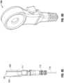
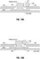
- a press studmay then be introduced into connector 100 by, for example, placing connector 100 over a press stud such that the bulbous end press stud is positioned within opening 145, as shown in Fig. 10A .
- lever 110may then be moved to the closed position as illustrated in Fig. 2 , causing cam 102 to rotate towards moveable leg 132 of V-spring 120.
- cam 102causes it to ride over detent 140 thereby compressing movable leg 132 in a proximal direction, which mechanically engages and electrically couples the press stud with narrow end 150 of opening 145, as shown in Fig. 10B .
- a press stud engaged with connector 100 as describedmay be disengaged by moving lever 110 from a closed position to an open position, causing cam 102 to rotate away from detent 140 and relax movable leg 132 of V-spring 120, which disengages the press stud and permits its removal as will be readily appreciated.
- an ECG electrode connector 1100is provided wherein a cam is configured to cause mechanical engagement between the press stud and an electrical contact member.
- a springmay be added to facilitate the opening and actuation of the lever 110.
- FIG. 4, 5 , 6A, and 6Banother embodiment according to the present disclosure provides an ECG lead wire connector 400 that includes a housing 405 which provides a cavity 406, and a pushbutton 410 having an external face 411 and an internal engaging surface 432.
- Connector 400may also include a cover 605 which optionally includes an identification marking 610 as previously described herein.
- Housing 405, pushbutton 410, cover 605may be constructed from any suitable non-conductive material as previously described.
- Pushbutton 410is slidably disposed within housing 405 and is biased in a distal direction by a coil spring 420 that is retained at its distal (pushbutton) end by a saddle 426 provided by pushbutton 410, and at its proximal (housing) end by a saddle 425 provided by housing 405.
- Pushbutton 410includes at least one stop member 436 which cooperates with stop members 435 and 437 provided within housing 405 to define the distal and proximal limits of travel, respectively, of pushbutton 410.
- Pushbutton 410includes an opening 430 disposed therein having an engaging surface 432 for coupling the connector 400 to a press stud as will be further described below.
- Connector 400further includes an electrical contact member 455 which is disposed upon cavity 406.
- Contact member 455is electrically coupled to a lead wire 475 by any suitable manner of connection as previously disclosed herein.
- Lead wire 475may optionally be supported at its exit point from housing 405 by a strain relief 470.
- Contact member 455provides a contact opening 445 defined therein to accept an electrical contact, such as a press stud, and may be an asymmetrical in shape as previously described herein, having a distal narrow end 450 and a proximal wide end 451.
- the bottom surface 630 of housing 405provides an aperture 620 disposed therein which exposes contact opening 445 to the exterior of connector 400 to facilitate insertion of a press stud into the connector.
- Engaging a press stud into connector 400may be accomplished by depressing pushbutton 410, by, for example, applying sufficient finger pressure to pushbutton face 411 so as to overcome the bias of coil spring 420, thereby moving pushbutton 410 from a distal locked position as shown in Fig. 4 to a proximal open position as shown in Fig 5 . Opening 430 correspondingly moves proximally, exposing the wide proximal end 451 of contact opening 445 and facilitating the insertion of a press stud into connector 400 as best shown in Fig. 6D .
- pushbutton 410may then be released whereupon the biasing force of coil spring 420 causes pushbutton 410 to move distally, causing engaging surface 432 to mechanically engage and electrically couple the press stud with narrow end 450 of contact opening 445, as best shown in Fig. 6C .
- a press stud engaged with connector 400 as describedmay be disengaged by depressing pushbutton 410, causing engaging surface 432 to move proximally, releasing the press stud and facilitating its removal from connector 400.
- pushbutton 410may be released, readying connector 400 for subsequent use. It is also contemplated in this embodiment to add components, such as linkages or gearing, between pushbutton and electrical contact member to achieve mechanical advantage and improved clamping or connection force.
- FIG. 7, 8 , 9A, and 9Bwherein is shown an ECG lead wire connector 700 having a housing 705 which provides a cavity 706, and a lever 710 pivotally disposed thereupon having an actuating end 715, an external pushbutton face 711, a pivot 712, and an engaging region 716.
- Connector 700may also include a cover 905 which optionally includes an identification marking 910 as previously described herein.
- Housing 705, lever 710, and cover 605may be constructed from any suitable non-conductive material as previously described herein.
- lever 710includes a pivot hole 713 disposed therein for pivotally engaging a pivot pin 714 that is provided by housing 705.
- Actuation end 715 of lever 710is biased in an outward direction by a leaf spring 720 that is retained at its lever end by surface 726 of lever 710, and at its housing end by a surface 725 of housing 705.
- leaf spring 720may include at least one tab (not shown) retained by at least one slot (not shown) provided by lever surface 726 and/or housing surface 725.
- Engaging region 716 of lever 710includes an engaging surface 732 for coupling the connector 700 to a press stud as will be further described below.
- Connector 700further includes an electrical contact member 755 which is disposed upon cavity 706.
- Contact member 755is electrically coupled to a lead wire 775 by any suitable manner of connection as previously disclosed herein.
- Lead wire 775may optionally be supported at its exit point from housing 705 by a strain relief 770.
- Contact member 755provides a contact opening 745 defined therein to accept an electrical contact, such as a press stud, and may be an asymmetrical in shape as previously described herein, having a narrow end 750 and a wide end 751 as best illustrated in Figs. 8 and 9B .
- the bottom surface 930 of housing 705provides an aperture 920 disposed therein which exposes contact opening 745 to the exterior of connector 700 to facilitate insertion of a press stud into the connector.
- Engaging a press stud into connector 700may be accomplished by depressing pushbutton face 711, by, for example, applying sufficient finger pressure thereto so as to overcome the bias of leaf spring 720, thereby causing engaging region 716 of lever 710 to swing from a closed position as shown in Fig. 7 to an open position as shown in Fig 8 .
- the wide end 751 of contact opening 745is thereby exposed thus facilitating the insertion of a press stud into connector 700.
- Pushbutton face 711may then be released whereupon the biasing force of leaf spring 720 causes engaging surface 732 to move toward the inserted press stud to mechanically engage and electrically couple the press stud with narrow end 750 of contact opening 745, as will be readily appreciated.
- a press stud engaged with connector 700 as describedmay be disengaged by depressing pushbutton 710, causing engaging surface 732 to swing away from the press stud (i.e., away from narrow end 750 of contact opening 745), releasing the press stud and facilitating its removal from connector 700.
- pushbutton face 711may then be released, readying connector 700 for subsequent use.
- an embodiment of an ECG electrode connector 1320includes a housing 1322 having an upper member 1324 and a lower member 1326, and defining an internal cavity 1328 therebetween.
- Housing 1322is fabricated from a non-conducting material, e.g., an injection molded polymer which electrically insulates the subject from the conductive element(s) therewithin.
- Upper member 1324 and lower member 1326are separate components attached to each other by any suitable method of bonding, such as without limitation, adhesive, ultrasonic welding, or heat welding.
- Upper member 1324 and lower member 1326form a non-conductive element of the housing 1322.
- Housing 1322includes a lead wire terminal 1330 which is electrically connected to a respective end of lead wire 1304 by any suitable method of connection, including without limitation, crimping, soldering, or welding. Housing 1322 supports a contact member 1332 that is electrically connected to lead wire terminal 1330. Contact member 1332 and lead wire terminal 1330 may be integrally formed. Contact member 1332 defines a contact opening 1334 formed therein and in communication with internal cavity 1328 of housing 1322.
- Contact opening 1334includes first contact opening portion 1334a and second contact opening portion 1334b.
- First contact opening portion 1334adefines an internal dimension or diameter which is greater than the corresponding internal dimension or diameter of second contact opening portion 1334b.
- Housing 1322further includes a lever 1340 pivotably connected thereto.
- Lever 1340includes an actuating end 1336.
- Lever 1340is biased to a first position by a biasing member 1338.
- Lever 1340includes an engaging region 1336a projecting therefrom so as to extend across first contact opening portion 1334a of contact opening 1334 when lever 1340 is in the first position.
- lever 1340is actuatable to a second position wherein engaging region 1336a thereof does not obstruct or extend across first contact opening portion 1334a of contact opening 1334.
- a clinicianmay apply finger pressure to actuating end 1336 that is sufficient to overcome the biasing force of biasing member 1338, thereby causing engaging region 1336a to move to a second position as herein described.
- ECG electrode connector 1320is adapted for connection to a conventional snap-type biomedical electrode (not explicitly shown).
- a typical snap-type biomedical electrodeincorporates an electrode flange or base and male press stud or terminal extending in transverse relation to the electrode base.
- the male press stud terminalmay have a bulbous head whereby an upper portion of the terminal has a greater cross-sectional dimension than a lower portion of the terminal.
- lever 1340 of electrode connector 1320when lever 1340 of electrode connector 1320 is in the second position, the head of the male press stud terminal of the snap-type biomedical electrode may be inserted into first contact opening portion 1334a of contact opening 1334 and actuating end 1336, and thus, lever 1340, may be released so that biasing member 1338 moves engaging region 1336a of lever 1340 against the head of the male press stud (not explicitly shown) to push or force the lower portion of the press stud into a second contact opening portion 1334b of contact opening 1334.
- the biasing force of biasing member 1338helps to maintain the press stud within second contact opening portion 1334b of contact opening 1334 and thus inhibits removal or disconnection of the biomedical electrode from ECG connector 1320.
Landscapes
- Health & Medical Sciences (AREA)
- Life Sciences & Earth Sciences (AREA)
- Medical Informatics (AREA)
- Biophysics (AREA)
- Pathology (AREA)
- Engineering & Computer Science (AREA)
- Biomedical Technology (AREA)
- Heart & Thoracic Surgery (AREA)
- Physics & Mathematics (AREA)
- Molecular Biology (AREA)
- Surgery (AREA)
- Animal Behavior & Ethology (AREA)
- General Health & Medical Sciences (AREA)
- Public Health (AREA)
- Veterinary Medicine (AREA)
- Cardiology (AREA)
- Details Of Connecting Devices For Male And Female Coupling (AREA)
- Measurement And Recording Of Electrical Phenomena And Electrical Characteristics Of The Living Body (AREA)
- Coupling Device And Connection With Printed Circuit (AREA)
Description
- This application claims priority to
U.S. Provisional Application Serial No. 61/012,825, filed December 11, 2007 - The present disclosure relates to biomedical electrodes, and in particular, to a biomedical electrode connector for attaching a lead wire to an electrocardiogram (ECG) electrode placed on a patient's body.
- Electrocardiograph (ECG) monitors are widely used to obtain medical (i.e. biopotential) signals containing information indicative of the electrical activity associated with the heart and pulmonary system. To obtain medical signals, ECG electrodes are applied to the skin of a patient in various locations. The electrodes, after being positioned on the patient, connect to an ECG monitor by a set of ECG lead wires. The distal end of the ECG lead wire, or portion closest to the patient, may include a connector which is adapted to operably connect to the electrode to receive medical signals from the body. The proximal end of the ECG lead set is operably coupled to the ECG monitor and supplies the medical signals received from the body to the ECG monitor.
- A typical ECG electrode assembly may include an electrically conductive layer and a backing layer, the assembly having a patient contact side and a connector side. The contact side of the electrode pad may include biocompatible conductive gel or adhesive for affixing the electrode to a patient's body for facilitating an appropriate electrical connection between a patient's body and the electrode assembly. The connector side of the pad may incorporate a metallic press stud having a bulbous profile for coupling the electrode pad to the ECG lead wire. In use, the clinician removes a protective covering from the electrode side to expose the gel or adhesive, affixes the electrode pad to the patient's body, and attaches the appropriate ECG lead wire connector to the press stud by pressing or "snapping" the lead wire connector onto the bulbous press stud to achieve mechanical and electrical coupling of the electrode and lead wire. After use, a clinician then removes the ECG lead wire connector from the pad by pulling or "unsnapping" the connector from the pad.
- The described ECG lead wire connector may have drawbacks. A clinician must apply considerable downward force on the lead wire connector to achieve positive engagement of the connector to the press stud. This high connecting force may cause additional and unnecessary discomfort or pain to the patient, whose existing medical condition may already be a source of discomfort or pain. A patient's discomfort may be compounded by the need to connect multiple electrodes which are customarily employed during ECG procedures.
- Upon completion of the ECG procedure, a clinician must unsnap the ECG lead wire connector from the pad, which may further cause discomfort to the patient. In some instances, the connector does not readily disengage from the press stud thus requiring the clinician to use considerable upward force to unseat the connector. Often, these attempts to decouple the ECG lead wire connector from the electrode press stud will instead cause the pad to be suddenly and painfully torn from the patient's skin. In other instances, attempts to detach the ECG lead wire will cause the pad to become partially dislodged from the patient, which may impair the electrode's ability to receive biopotential signals. This is undesirable when, for example, the clinician wishes to detach the lead wires temporarily yet wishes to leave the pads in place to perform ECG testing on the patient at a future time.
- In yet other instances, a snap lock connector may engage the press stud with insufficient force, which may cause suboptimal signal transmission from the electrode to the lead wire, as well as allowing the connector to be disengaged inadvertently by, for example, a slight tug on the lead wire. These effects are undesirable, because they may invalidate the ECG procedure, requiring time-consuming re-testing of the patient, or may lead to delayed, inaccurate or unreliable test results.
- Additionally, the process of snapping and unsnapping lead wire connectors from ECG pads, while simultaneously striving to avoid the above-mentioned adverse effects, requires considerable manual dexterity on the part of the ECG clinician. Since clinicians typically repeat the electrode connection/disconnection routine many times each day, the described drawbacks may lead to clinician discontentment and fatigue.
- The invention is defined in claim 1. Preferred embodiments are set out in the dependent claims.
- Various embodiments of the presently disclosed ECG electrode connector are disclosed herein with reference to the drawings, wherein:
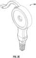
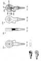
Fig. 1 is a schematic diagram of an embodiment of an ECG electrode connector in accordance with the present disclosure having a thumb cam lever in an open position;Fig. 2 illustrates the ECG connector ofFig. 1 having a thumb cam lever in a closed position in accordance with the present disclosure;Fig. 3A is a top view of theFig. 1 embodiment of an ECG electrode connector in accordance with the present disclosure;Fig. 3B is a bottom view of theFig. 1 embodiment of an ECG electrode connector in accordance with the present disclosure;Fig. 3C is a side view of theFig. 1 embodiment of an ECG electrode connector in accordance with the present disclosure;Fig. 3D is a side cutaway view of theFig. 1 embodiment of an ECG electrode connector in accordance with the present disclosure;Fig. 3E is an oblique view of theFig. 1 embodiment of an ECG electrode connector in accordance with the present disclosure;Fig. 4 is a schematic diagram of another embodiment of an ECG electrode connector in accordance with the present disclosure having a pushbutton in a released position;Fig. 5 illustrates the ECG connector ofFig. 4 having a pushbutton in a depressed position in accordance with the present disclosure;Fig. 6A is a top view of theFig. 4 embodiment of an ECG electrode connector in accordance with the present disclosure;Fig. 6B is a bottom view of theFig. 4 embodiment of an ECG electrode connector in accordance with the present disclosure;Fig. 6C is a side cutaway view of theFig. 4 embodiment of an ECG electrode connector having a pushbutton in a released position in accordance with the present disclosure;Fig. 6D is a side cutaway view of theFig. 4 embodiment of an ECG electrode connector having a pushbutton in a depressed position in accordance with the present disclosure;Fig. 7 is a schematic diagram of yet another embodiment of an ECG electrode connector in accordance with the present disclosure having a pivoting lever pushbutton in a released position;Fig. 8 illustrates the ECG connector ofFig.7 having a pivoting lever pushbutton in a depressed position in accordance with the present disclosure;Fig. 9A is a top view of theFig. 7 embodiment of an ECG electrode connector in accordance with the present disclosure;Fig. 9B is a bottom view of theFig. 7 embodiment of an ECG electrode connector in accordance with the present disclosure;Fig. 9C is a side view of theFig. 7 embodiment of an ECG electrode connector in accordance with the present disclosure;Fig. 9D is an oblique view of theFig. 7 embodiment of an ECG electrode connector in accordance with the present disclosure;Fig. 10A is an exemplary side detail view of an ECG electrode connector in accordance with the present disclosure disengaged from a press stud of an ECG pad;Fig. 10B is an exemplary side detail view of an ECG electrode connector in accordance with the present disclosure engaging a press stud of an ECG pad;Fig. 11A is a schematic diagram of still another embodiment of an ECG electrode connector in accordance with the present disclosure having a thumb cam lever in a closed position;Fig. 11B illustrates the ECG connector ofFig.11A having a thumb cam lever in an open position in accordance with the present disclosure;Fig. 12A is an exploded view of a yet another embodiment of an ECG electrode connector in accordance with the present disclosure;Fig. 12B is a bottom view of theFig. 12A embodiment of an ECG electrode connector in accordance with the present disclosure;Fig. 12C is an oblique view of theFig. 12A embodiment of an ECG electrode connector in accordance with the present disclosure;Fig. 13A is a schematic diagram of theFig. 12A embodiment of an ECG electrode connector in accordance with the present disclosure;Fig. 13B is a top view of theFig. 12A embodiment of an ECG electrode connector in accordance with the present disclosure;Fig. 13C is a side view of theFig. 12A embodiment of an ECG electrode connector in accordance with the present disclosure; andFig. 13D is a bottom view of theFig. 12A embodiment of an ECG electrode connector in accordance with the present disclosure. Only the embodiments fromfigure 7 onwards are part of the claimed invention.- Embodiments of the presently disclosed ECG electrode connector are described herein in detail with reference to the drawings, in which like reference numerals designate identical or corresponding elements in each of the several views. As shown in the drawings and as described throughout the following description, and as is traditional when referring to relative positioning on an object, the term "proximal" refers to the end of the apparatus which is closer to the monitor and the term "distal" refers to the end of the apparatus which is further from the monitor. In the following description, well-known functions or constructions are not described in detail to avoid obscuring the present disclosure in unnecessary detail.
- Referring to
Figs. 1, 2 , and3A , there is shown an embodiment of anECG electrode connector 100 having athumb cam lever 110. Theconnector 100 includes ahousing 105 that includes acavity 106, apivot pin 115, and athumb cam lever 110 having apivot hole 116 defined therein dimensioned to pivotably couplethumb cam lever 110 to pivotpin 115.Connector 100 may also include acover 305 which optionally includes an identification marking 310 which may be incorporated withcover 305 by any suitable means, including without limitation printing, engraving, silk screening, stamping, or integrally molding said marking 310 ontocover 305. Thehousing 105,lever 110 and cover 305 may be constructed of any suitable non-conductive material, including without limitation any thermoplastic and/or elastomeric polymer such as polybutylene terephthalate (PBT), polyethylene terephthalate (PET), polyvinyl chloride (PVC), acrylonitrile butadiene styrene (ABS), thermoplastic polyurethanes (TPU), thermoplastic vulcanates (TPV), polypropylene (PP), polyethylene (PE), and/or fiber-reinforced polymer (FRP). - A V-
spring 120 having acoil base 130, afixed leg 131 and amovable leg 132 is coupled tohousing 110 withincavity 106.Coil base 130 of V-spring 120 may be multi-turn, single-turn, or a V-shaped apex without a coil. V-spring 120 is retained at its base bypin 117 and is joined tohousing 105 at its fixed end bysaddle 125 such thatmovable leg 132 is biased in a distal direction, i.e., towardspivot pin 115. Additionally or alternatively, V-spring 120 may be joined to saddle 125 orcavity 106 by any suitable manner of bonding, such as by adhesive or heat welding. Astop 135 limits the outward flexure ofmovable leg 132.Thumb cam lever 110 includes acam 102 which communicates with adetent 140 ofspring member 120 whenthumb cam lever 120 moves to a closed position, as shown inFig. 2 .Detent 140 andcam 102 cooperate to lockthumb cam lever 110 in a closed position, and additionally or alternatively, provide tactile feedback to a clinician. Additional locking and tactile feedback may be provided by the engagement of alever detent 160 with a corresponding dimple (not shown) provided onthumb cam lever 110. Alever recess 180 may be provided byhousing 105 to receivelever 110 whenlever 110 is in the closed position. Afinger recess 165 is provided onhousing 105 to facilitate manipulation and/or grasping ofthumb cam lever 110 by the clinician. Connector 100 further includes anelectrical contact member 155 which is disposed uponcavity 106.Contact member 155 may be constructed from any suitable electrically conductive material, including without limitation stainless steel or low-carbon steel. It is also envisionedcontact member 155 may be constructed of a non-conductive material having a conductive coating.Contact member 155 is electrically coupled to alead wire 175 by any suitable manner of connection, such as acrimp 156, or additionally or alternatively, soldering or wire bonding.Lead wire 175 may optionally be supported at its exit point fromhousing 105 by astrain relief 170.Contact member 155 provides acontact opening 145 defined therein to accept an electrical contact, such as a bulbous press stud of an ECG pad. In the embodiment, thecontact opening 145 may be asymmetrical in shape, such as, for example, an ovoid shape dimensioned at itswide end 151 to accept the bulbous press stud, and dimensioned at itsnarrow end 150 to capture the narrow waist portion of the press stud. Referring now toFigs. 3B ,3D ,10A and 10B , thebottom surface 330 ofhousing 105 provides anaperture 320 disposed therein which exposes contact opening 145 to the exterior ofconnector 100 to facilitate insertion of a press stud into the connector.- Engaging a press stud into
connector 100 may be accomplished by positioninglever 110 to an open position as shown inFig. 1 , whereuponcam 102 rotates away fromdetent 140, permittingmovable leg 132 of V-spring 120 to flex distally and come to rest uponstop 135. A press stud may then be introduced intoconnector 100 by, for example, placingconnector 100 over a press stud such that the bulbous end press stud is positioned withinopening 145, as shown inFig. 10A . Subsequent to insertion of the press stud,lever 110 may then be moved to the closed position as illustrated inFig. 2 , causingcam 102 to rotate towardsmoveable leg 132 of V-spring 120. The rotation ofcam 102 causes it to ride overdetent 140 thereby compressingmovable leg 132 in a proximal direction, which mechanically engages and electrically couples the press stud withnarrow end 150 ofopening 145, as shown inFig. 10B . Conversely, a press stud engaged withconnector 100 as described may be disengaged by movinglever 110 from a closed position to an open position, causingcam 102 to rotate away fromdetent 140 and relaxmovable leg 132 of V-spring 120, which disengages the press stud and permits its removal as will be readily appreciated. In another embodiment as shown inFigs. 11A and 11B in, anECG electrode connector 1100 is provided wherein a cam is configured to cause mechanical engagement between the press stud and an electrical contact member. A spring may be added to facilitate the opening and actuation of thelever 110. - Turning now to
Figs. 4, 5 ,6A, and 6B , another embodiment according to the present disclosure provides an ECGlead wire connector 400 that includes ahousing 405 which provides acavity 406, and apushbutton 410 having anexternal face 411 and an internalengaging surface 432.Connector 400 may also include acover 605 which optionally includes an identification marking 610 as previously described herein.Housing 405,pushbutton 410, cover 605 may be constructed from any suitable non-conductive material as previously described. Pushbutton 410 is slidably disposed withinhousing 405 and is biased in a distal direction by acoil spring 420 that is retained at its distal (pushbutton) end by asaddle 426 provided bypushbutton 410, and at its proximal (housing) end by asaddle 425 provided byhousing 405.Pushbutton 410 includes at least onestop member 436 which cooperates withstop members housing 405 to define the distal and proximal limits of travel, respectively, ofpushbutton 410.Pushbutton 410 includes an opening 430 disposed therein having anengaging surface 432 for coupling theconnector 400 to a press stud as will be further described below.Connector 400 further includes anelectrical contact member 455 which is disposed uponcavity 406.Contact member 455 is electrically coupled to alead wire 475 by any suitable manner of connection as previously disclosed herein.Lead wire 475 may optionally be supported at its exit point fromhousing 405 by astrain relief 470.Contact member 455 provides acontact opening 445 defined therein to accept an electrical contact, such as a press stud, and may be an asymmetrical in shape as previously described herein, having a distalnarrow end 450 and a proximalwide end 451. Thebottom surface 630 ofhousing 405 provides anaperture 620 disposed therein which exposes contact opening 445 to the exterior ofconnector 400 to facilitate insertion of a press stud into the connector.- Engaging a press stud into
connector 400 may be accomplished by depressingpushbutton 410, by, for example, applying sufficient finger pressure topushbutton face 411 so as to overcome the bias ofcoil spring 420, thereby movingpushbutton 410 from a distal locked position as shown inFig. 4 to a proximal open position as shown inFig 5 . Opening 430 correspondingly moves proximally, exposing the wideproximal end 451 ofcontact opening 445 and facilitating the insertion of a press stud intoconnector 400 as best shown inFig. 6D . - Subsequent to insertion of a press stud,
pushbutton 410 may then be released whereupon the biasing force ofcoil spring 420 causes pushbutton 410 to move distally, causing engagingsurface 432 to mechanically engage and electrically couple the press stud withnarrow end 450 ofcontact opening 445, as best shown inFig. 6C . Conversely, a press stud engaged withconnector 400 as described may be disengaged by depressingpushbutton 410, causing engagingsurface 432 to move proximally, releasing the press stud and facilitating its removal fromconnector 400. Upon removal of the press stud,pushbutton 410 may be released, readyingconnector 400 for subsequent use. It is also contemplated in this embodiment to add components, such as linkages or gearing, between pushbutton and electrical contact member to achieve mechanical advantage and improved clamping or connection force. - Yet another embodiment in accordance with the present disclosure is described with reference to
Figs. 7, 8 ,9A, and 9B , wherein is shown an ECGlead wire connector 700 having ahousing 705 which provides acavity 706, and alever 710 pivotally disposed thereupon having anactuating end 715, anexternal pushbutton face 711, apivot 712, and anengaging region 716.Connector 700 may also include acover 905 which optionally includes an identification marking 910 as previously described herein.Housing 705,lever 710, and cover 605 may be constructed from any suitable non-conductive material as previously described herein. - As shown in
Figs. 7 and 8 ,lever 710 includes apivot hole 713 disposed therein for pivotally engaging apivot pin 714 that is provided byhousing 705.Actuation end 715 oflever 710 is biased in an outward direction by aleaf spring 720 that is retained at its lever end bysurface 726 oflever 710, and at its housing end by asurface 725 ofhousing 705. Additionally or alternatively,leaf spring 720 may include at least one tab (not shown) retained by at least one slot (not shown) provided bylever surface 726 and/orhousing surface 725.Engaging region 716 oflever 710 includes anengaging surface 732 for coupling theconnector 700 to a press stud as will be further described below. Connector 700 further includes anelectrical contact member 755 which is disposed uponcavity 706.Contact member 755 is electrically coupled to alead wire 775 by any suitable manner of connection as previously disclosed herein.Lead wire 775 may optionally be supported at its exit point fromhousing 705 by astrain relief 770.Contact member 755 provides acontact opening 745 defined therein to accept an electrical contact, such as a press stud, and may be an asymmetrical in shape as previously described herein, having anarrow end 750 and awide end 751 as best illustrated inFigs. 8 and9B . Thebottom surface 930 ofhousing 705 provides anaperture 920 disposed therein which exposes contact opening 745 to the exterior ofconnector 700 to facilitate insertion of a press stud into the connector.- Engaging a press stud into
connector 700 may be accomplished by depressingpushbutton face 711, by, for example, applying sufficient finger pressure thereto so as to overcome the bias ofleaf spring 720, thereby causingengaging region 716 oflever 710 to swing from a closed position as shown inFig. 7 to an open position as shown inFig 8 . Thewide end 751 ofcontact opening 745 is thereby exposed thus facilitating the insertion of a press stud intoconnector 700. Pushbutton face 711 may then be released whereupon the biasing force ofleaf spring 720causes engaging surface 732 to move toward the inserted press stud to mechanically engage and electrically couple the press stud withnarrow end 750 ofcontact opening 745, as will be readily appreciated. Conversely, a press stud engaged withconnector 700 as described may be disengaged by depressingpushbutton 710, causing engagingsurface 732 to swing away from the press stud (i.e., away fromnarrow end 750 of contact opening 745), releasing the press stud and facilitating its removal fromconnector 700. Upon removal of the press stud,pushbutton face 711 may then be released, readyingconnector 700 for subsequent use. - With reference now to
Figs 12A-C andFigs. 13 A-D , an embodiment of anECG electrode connector 1320 includes ahousing 1322 having anupper member 1324 and alower member 1326, and defining aninternal cavity 1328 therebetween.Housing 1322 is fabricated from a non-conducting material, e.g., an injection molded polymer which electrically insulates the subject from the conductive element(s) therewithin.Upper member 1324 andlower member 1326 are separate components attached to each other by any suitable method of bonding, such as without limitation, adhesive, ultrasonic welding, or heat welding.Upper member 1324 andlower member 1326 form a non-conductive element of thehousing 1322. Housing 1322 includes alead wire terminal 1330 which is electrically connected to a respective end oflead wire 1304 by any suitable method of connection, including without limitation, crimping, soldering, or welding.Housing 1322 supports acontact member 1332 that is electrically connected to leadwire terminal 1330.Contact member 1332 andlead wire terminal 1330 may be integrally formed.Contact member 1332 defines acontact opening 1334 formed therein and in communication withinternal cavity 1328 ofhousing 1322.Contact opening 1334 includes first contact opening portion 1334a and second contact opening portion 1334b. First contact opening portion 1334a defines an internal dimension or diameter which is greater than the corresponding internal dimension or diameter of second contact opening portion 1334b.Housing 1322 further includes alever 1340 pivotably connected thereto.Lever 1340 includes anactuating end 1336.Lever 1340 is biased to a first position by a biasing member 1338.Lever 1340 includes anengaging region 1336a projecting therefrom so as to extend across first contact opening portion 1334a ofcontact opening 1334 whenlever 1340 is in the first position. In use,lever 1340 is actuatable to a second position wherein engagingregion 1336a thereof does not obstruct or extend across first contact opening portion 1334a ofcontact opening 1334. For example, a clinician may apply finger pressure to actuatingend 1336 that is sufficient to overcome the biasing force of biasing member 1338, thereby causingengaging region 1336a to move to a second position as herein described.ECG electrode connector 1320 is adapted for connection to a conventional snap-type biomedical electrode (not explicitly shown). A typical snap-type biomedical electrode incorporates an electrode flange or base and male press stud or terminal extending in transverse relation to the electrode base. The male press stud terminal may have a bulbous head whereby an upper portion of the terminal has a greater cross-sectional dimension than a lower portion of the terminal. Accordingly, in use, whenlever 1340 ofelectrode connector 1320 is in the second position, the head of the male press stud terminal of the snap-type biomedical electrode may be inserted into first contact opening portion 1334a ofcontact opening 1334 and actuatingend 1336, and thus,lever 1340, may be released so that biasing member 1338moves engaging region 1336a oflever 1340 against the head of the male press stud (not explicitly shown) to push or force the lower portion of the press stud into a second contact opening portion 1334b ofcontact opening 1334. The biasing force of biasing member 1338 helps to maintain the press stud within second contact opening portion 1334b ofcontact opening 1334 and thus inhibits removal or disconnection of the biomedical electrode fromECG connector 1320.- It will be understood that various modifications may be made to the embodiments disclosed herein. Further variations of the above-disclosed and other features and functions, or alternatives thereof, may be desirably combined into many other different systems, instruments and applications. Various presently unforeseen or unanticipated alternatives, modifications, variations or improvements therein may be subsequently made by those skilled in the art, which are also intended to be encompassed by the following claims.
Claims (16)
- An ECG lead wire connector (700, 1320), comprising:an electrical contact member (755, 1332), wherein the electrical contact member (755, 1332) defines a contact plane and wherein the electrical contact member (755, 1332) provides a contact opening (745, 1334) configured to receive a press stud of an ECG electrode pad;a pivoting lever (710, 1340), which is depressible by a user, the pivoting lever (710, 1340) having a pivot (712), an engaged position when no pressure is applied to the pivoting lever (710, 1340) by the user and a disengaged position when the pivoting lever (710, 1340) is depressed by the user; and,wherein the pivoting lever (710, 1340) is biased to the engaged position by a spring member (720, 1338);CHARACTERISED IN THAT the ECG lead wire connector further comprises:a housing (705, 1322) comprising the electrical contact member, wherein the housing is constructed from a non-conductive material;wherein the pivoting lever (710, 1340) is constructed from a non-conductive material, is pivotably disposed upon the housing (705, 1322); is pivotable about an axis orthogonal to the contact plane; and, further comprises an actuating end (715, 1336) with an external face (711), and an engaging region (716, 1336a) having an internal engaging surface (732), wherein the external face (711) is external to the housing (705), and wherein the internal engaging surface (732) is inside the housing (705, 1322);wherein the spring member (720, 1338) comprises a lever end and a housing end, wherein the spring member (720, 1338) is retained at its lever end by a surface (726) of the pivoting lever (710, 1340) and at its housing end by a surface (725) of the housing (705, 1322);wherein the internal engaging surface (732) of the pivoting lever (710, 1340) is configured to allow the insertion of the press stud into the contact opening (745, 1334) of the electrical contact member (755, 1332) when the external face (711) of the pivoting lever (710, 1340) is depressed by the user to pivot the pivoting lever (710, 1340) to the disengaged position; and,wherein the internal engaging surface (723) is configured to push the press stud into electrical contact with the electrical contact member (755, 1332) in the contact opening (745, 1334) when the pivoting lever (710, 1340) is biased by the spring member (720, 1338) to pivot from the disengaged position to the engaged position.
- The ECG lead wire connector (700, 1320) according to claim 1, wherein the spring member (720, 1338) is a leaf spring.
- The ECG lead wire connector (700, 1320) according to any one of the preceding claims, wherein the pivoting lever (710, 1340) includes a pivot hole (713) for pivotally engaging a pivot pin (714) provided by the housing (705, 1322).
- The ECG lead wire connector (700, 1320) according to any one of the preceding claims, wherein the external face (711) of the pivoting lever (710, 1340) is biased to the engaged position by a leaf spring (720, 1338), wherein the leaf spring (720, 1338) is retained at a first end (726) by a surface of the pivoting lever (710, 1340), and at a second end (725) by a surface of housing (705, 1322).
- The ECG lead wire connector (700, 1320) according to Claim 1, wherein the contact opening (745, 1334) has a narrow end (750, 1334a) and a wide end (751, 1334b).
- The ECG lead wire connector (700, 1320) according to Claim 5, wherein the opening (745, 1334) is dimensioned at the wide end (751, 1334b) to accept a bulbous portion of the press stud and dimensioned at the narrow end (750, 1334a) to accept a narrow waist portion of the press stud.
- The ECG lead wire connector (700, 1320) according to any one of Claims 5 or 6, wherein the contact opening (745, 1334) is configured such that, when the pivoting lever (710, 1340) is in the engaged position, the press stud is biased against the narrow end (750, 1334a) of the contact opening (745, 1334).
- The ECG lead wire connector (700, 1320) according to any one of the preceding claims, wherein a pivot plane is defined by the pivoting of the pivoting lever (710, 1340) between the engaged position and disengaged position; and, wherein the pivot plane is parallel to the contact plane and adjacent to the contact plane.
- The ECG lead wire connector (700, 1320) according to Claim 8, wherein the pivot plane is positioned above the contact plane.
- The ECG lead wire connector (700, 1320) according to any one of the preceding claims, wherein the pivot is located between the engaging region and the actuating end.
- The ECG lead wire connector (700, 1320) according to any one of the preceding claims, wherein the contact opening (745, 1334) is pear-shaped.
- The ECG lead wire connector according to any one of the preceding claims, wherein the external face (711) of the pivoting lever (710, 1340) provides a pushbutton external face.
- The ECG lead wire connector according to any one of claims 1, 3 and 5-12, wherein the spring member (720, 1338) is a coil spring.
- The ECG lead wire connector according to any one of the preceding claims, wherein the housing (705, 1322) is fabricated from an injection molded polymer.
- The ECG lead wire connector (700, 1320) according to any one of the preceding claims, wherein the engaging region (716, 1336a) of the pivoting lever (710) extends across the contact opening (745, 1334) of the electrical contact member (755, 1332) when the pivoting lever (710, 1340) is biased by the spring member (720, 1338) to the engaged position.
- The ECG lead wire connector (700, 1320) according to Claim 15, wherein the contact opening (745, 1334) comprises a first contact opening portion (1334a) and a second contact opening portion (1334b) and wherein the first contact opening portion (1334a) defines an internal dimension or diameter which is greater than the corresponding internal dimension or diameter of second contact opening portion (1334b).
Applications Claiming Priority (3)
| Application Number | Priority Date | Filing Date | Title |
|---|---|---|---|
| US1282507P | 2007-12-11 | 2007-12-11 | |
| EP14197698.5AEP2856938B1 (en) | 2007-12-11 | 2008-12-10 | ECG electrode connector |
| EP08171185.5AEP2070474B1 (en) | 2007-12-11 | 2008-12-10 | ECG Electrode Connector |
Related Parent Applications (2)
| Application Number | Title | Priority Date | Filing Date |
|---|---|---|---|
| EP14197698.5ADivisionEP2856938B1 (en) | 2007-12-11 | 2008-12-10 | ECG electrode connector |
| EP08171185.5ADivisionEP2070474B1 (en) | 2007-12-11 | 2008-12-10 | ECG Electrode Connector |
Publications (3)
| Publication Number | Publication Date |
|---|---|
| EP3473175A1 EP3473175A1 (en) | 2019-04-24 |
| EP3473175B1true EP3473175B1 (en) | 2025-02-12 |
| EP3473175C0 EP3473175C0 (en) | 2025-02-12 |
Family
ID=40265975
Family Applications (4)
| Application Number | Title | Priority Date | Filing Date |
|---|---|---|---|
| EP12187209.7AActiveEP2545849B1 (en) | 2007-12-11 | 2008-12-10 | Ecg electrode connector |
| EP14197698.5AActiveEP2856938B1 (en) | 2007-12-11 | 2008-12-10 | ECG electrode connector |
| EP18193825.9AActiveEP3473175B1 (en) | 2007-12-11 | 2008-12-10 | Ecg electrode connector |
| EP08171185.5AActiveEP2070474B1 (en) | 2007-12-11 | 2008-12-10 | ECG Electrode Connector |
Family Applications Before (2)
| Application Number | Title | Priority Date | Filing Date |
|---|---|---|---|
| EP12187209.7AActiveEP2545849B1 (en) | 2007-12-11 | 2008-12-10 | Ecg electrode connector |
| EP14197698.5AActiveEP2856938B1 (en) | 2007-12-11 | 2008-12-10 | ECG electrode connector |
Family Applications After (1)
| Application Number | Title | Priority Date | Filing Date |
|---|---|---|---|
| EP08171185.5AActiveEP2070474B1 (en) | 2007-12-11 | 2008-12-10 | ECG Electrode Connector |
Country Status (8)
| Country | Link |
|---|---|
| US (7) | US8038484B2 (en) |
| EP (4) | EP2545849B1 (en) |
| CN (2) | CN101491438B (en) |
| CA (1) | CA2646037C (en) |
| DK (1) | DK2856938T3 (en) |
| ES (2) | ES2705536T3 (en) |
| MX (2) | MX2008015927A (en) |
| PT (1) | PT2856938T (en) |
Families Citing this family (54)
| Publication number | Priority date | Publication date | Assignee | Title |
|---|---|---|---|---|
| US8109883B2 (en) | 2006-09-28 | 2012-02-07 | Tyco Healthcare Group Lp | Cable monitoring apparatus |
| US8668651B2 (en) | 2006-12-05 | 2014-03-11 | Covidien Lp | ECG lead set and ECG adapter system |
| US8038484B2 (en) | 2007-12-11 | 2011-10-18 | Tyco Healthcare Group Lp | ECG electrode connector |
| US8452409B2 (en)* | 2008-01-07 | 2013-05-28 | Empi Inc. | Systems and methods for therapeutic electrical stimulation |
| US8386032B2 (en) | 2008-01-07 | 2013-02-26 | Empi Inc. | Systems and methods for therapeutic electrical stimulation |
| KR101028584B1 (en)* | 2008-08-27 | 2011-04-12 | 주식회사 바이오프로테크 | Disposable induction electrode and lead wire connected thereto |
| USD737979S1 (en) | 2008-12-09 | 2015-09-01 | Covidien Lp | ECG electrode connector |
| US8386054B2 (en)* | 2009-07-30 | 2013-02-26 | Richard B. North | Modular electrode and insertion tool |
| US8694080B2 (en) | 2009-10-21 | 2014-04-08 | Covidien Lp | ECG lead system |
| EP2339696A1 (en)* | 2009-12-22 | 2011-06-29 | General Electric Company | Electrical connector assembly |
| US8197276B2 (en) | 2010-08-13 | 2012-06-12 | Djo, Llc | Low profile connector system |
| EP2446865A1 (en) | 2010-10-28 | 2012-05-02 | Louise Mohn | Thermostimulation apparatus |
| EP2706920A4 (en)* | 2011-05-13 | 2014-11-05 | Parace Llc | Medical examination apparatus |
| US20120294466A1 (en)* | 2011-05-18 | 2012-11-22 | Stefan Kristo | Temporary anchor for a hearing prosthesis |
| CN102283644A (en)* | 2011-05-31 | 2011-12-21 | 青岛光电医疗科技有限公司 | Disposable hidden line integrated electrode and connector |
| ES2762190T3 (en) | 2011-07-22 | 2020-05-22 | Kpr Us Llc | ECG electrode connector |
| US20130023750A1 (en)* | 2011-07-22 | 2013-01-24 | Tyco Healthcare Group Lp | Ecg electrode system |
| USD707837S1 (en)* | 2011-10-14 | 2014-06-24 | Luzmon Uk Limited | Pad |
| IL218146A (en)* | 2012-02-16 | 2016-02-29 | New N I Medical (2011) Ltd | Biomedical electrode assembly |
| JP6101435B2 (en)* | 2012-05-10 | 2017-03-22 | 矢崎総業株式会社 | connector |
| US8956176B1 (en) | 2012-09-27 | 2015-02-17 | Cleveland Medical Devices Inc. | Lead wire connector for measuring electrophysiological signals |
| US9226680B1 (en)* | 2013-02-12 | 2016-01-05 | David Kendricks | Patient electrode connectors for electrocardiograph monitoring system |
| WO2014135374A1 (en)* | 2013-03-06 | 2014-09-12 | Dsm Ip Assets B.V. | A polymeric cover and a part of an electrical cable |
| CN105120742B (en)* | 2013-03-15 | 2017-07-28 | 柯惠有限合伙公司 | Electrode connector with conductive component |
| US9159209B2 (en) | 2013-03-15 | 2015-10-13 | Ut-Battelle, Llc | Conductive fabric seal |
| US9408546B2 (en)* | 2013-03-15 | 2016-08-09 | Covidien Lp | Radiolucent ECG electrode system |
| WO2014152425A1 (en)* | 2013-03-15 | 2014-09-25 | Covidien Lp | Radiolucent ecg electrode system |
| USD771818S1 (en) | 2013-03-15 | 2016-11-15 | Covidien Lp | ECG electrode connector |
| JP6031622B2 (en) | 2013-06-05 | 2016-11-24 | コーニンクレッカ フィリップス エヌ ヴェKoninklijke Philips N.V. | Adapter, electrode assembly and connector assembly |
| US10046465B2 (en)* | 2013-06-06 | 2018-08-14 | Seiko Epson Corporation | Attaching and detaching device and robot |
| US9325107B2 (en) | 2013-10-17 | 2016-04-26 | Neuralynx, Inc. | Electrical connector assembly for neural monitoring device and method of using same |
| FR3013580B1 (en)* | 2013-11-22 | 2018-01-12 | B.Braun Medical Sas | DEVICE FOR DERIVING EGG FROM A CATHETER |
| US9124056B1 (en)* | 2014-03-19 | 2015-09-01 | Doug Mockett & Company, Inc. | Rotating power grommet |
| US10357172B2 (en)* | 2014-05-16 | 2019-07-23 | Technical Services For Electronics, Inc. | Electrode lead wire connector |
| CN104352236B (en)* | 2014-09-30 | 2016-09-07 | 青岛光电医疗科技有限公司 | Encircle electrode |
| US10122117B2 (en)* | 2015-04-14 | 2018-11-06 | Te Connectivity Corporation | Quick connect power connector system |
| US20160360988A1 (en)* | 2015-06-15 | 2016-12-15 | Igor Abramov | Ecg leads |
| US10398335B2 (en) | 2015-08-05 | 2019-09-03 | Preventice Technologies, Inc. | Bridge connectors employing flexible planar bodies having signal pathways coupling control devices with biometric sensors |
| US9997861B2 (en) | 2015-12-10 | 2018-06-12 | International Business Machines Corporation | Force limiting latch indicator |
| KR102491281B1 (en) | 2016-01-05 | 2023-01-26 | 삼성전자주식회사 | Electrode assembly for measuring bio-signals |
| US9985374B2 (en)* | 2016-05-06 | 2018-05-29 | Tc1 Llc | Compliant implantable connector and methods of use and manufacture |
| JP6806606B2 (en) | 2017-03-23 | 2021-01-06 | 日本航空電子工業株式会社 | connector |
| US10959635B2 (en)* | 2017-10-02 | 2021-03-30 | Biosense Webster (Israel) Ltd. | Random pinout catheter |
| US10992078B2 (en) | 2018-01-29 | 2021-04-27 | Bard Access Systems, Inc. | Connection system for establishing an electrical connection through a drape and methods thereof |
| CN108478212B (en)* | 2018-04-13 | 2024-08-23 | 深圳市尤迈医疗用品有限公司 | Electrocardiogram lead wire |
| EP3793464A4 (en) | 2018-05-18 | 2021-07-21 | Bard Access Systems, Inc. | CONNECTION SYSTEM AND METHOD FOR MAKING AN ELECTRICAL CONNECTION THROUGH A COVERING CLOTH |
| EP3614503B1 (en)* | 2018-08-20 | 2023-12-20 | ODU GmbH & Co. KG | Flat angular connector with latch mechanism |
| CN111096739B (en)* | 2019-06-14 | 2025-01-10 | 安徽诺心医疗服务有限公司 | Rotary connection type wire connector |
| CN111110226B (en)* | 2019-06-14 | 2024-07-23 | 安徽诺心医疗服务有限公司 | Electrode plate wire connector with transverse buckling connection |
| CN111110227A (en)* | 2019-06-14 | 2020-05-08 | 安徽诺心医疗服务有限公司 | Elastic piece clamping type wire connector |
| CN111053550B (en)* | 2019-06-14 | 2024-10-29 | 安徽诺心医疗服务有限公司 | Electrode slice wire connector of horizontal connection |
| CN114174878B (en) | 2019-07-29 | 2024-07-30 | 巴德阿克塞斯系统股份有限公司 | Connection system and method for establishing optical and electrical connections through a drape |
| US12029498B2 (en) | 2019-08-08 | 2024-07-09 | Bard Access Systems, Inc. | Optical-fiber connector modules including shape-sensing systems and methods thereof |
| TWM653938U (en)* | 2023-10-11 | 2024-04-11 | 進聯工業股份有限公司 | Improved structure of wire quick connector |
Family Cites Families (438)
| Publication number | Priority date | Publication date | Assignee | Title |
|---|---|---|---|---|
| GB162804A (en) | 1920-02-06 | 1921-05-06 | Joseph Ernest Barrows | Improvements in terminals for electric cables |
| US3606881A (en) | 1970-02-20 | 1971-09-21 | Riley D Woodson | Conductive rubber electrode |
| US3805769A (en) | 1971-08-27 | 1974-04-23 | R Sessions | Disposable electrode |
| US3752151A (en) | 1971-08-30 | 1973-08-14 | Texas Instruments Inc | Disposable medical electrode with laminate contact member |
| US3828766A (en) | 1972-08-14 | 1974-08-13 | Jet Medical Prod Inc | Disposable medical electrode |
| US3829826A (en)* | 1972-08-22 | 1974-08-13 | Hewlett Packard Co | Cable fastener for electrocardiograph electrodes |
| US3842394A (en) | 1973-03-06 | 1974-10-15 | Medical Plastics Inc | Electrical connector for plate electrode |
| US3895635A (en) | 1973-06-20 | 1975-07-22 | Ndm Corp | Electrosurgical grounding cable assembly |
| US3868946A (en) | 1973-07-13 | 1975-03-04 | James S Hurley | Medical electrode |
| US3901218A (en) | 1973-10-26 | 1975-08-26 | Martin Buchalter | Disposable electrode |
| US3888240A (en) | 1974-02-08 | 1975-06-10 | Survival Technology | Electrode assembly and methods of using the same in the respiratory and/or cardiac monitoring of an infant |
| US4077397A (en) | 1974-10-07 | 1978-03-07 | Baxter Travenol Laboratories, Inc. | Diagnostic electrode assembly |
| US3998213A (en) | 1975-04-08 | 1976-12-21 | Bio-Volt Corporation | Self-adjustable holder for automatically positioning electroencephalographic electrodes |
| US3997225A (en) | 1975-07-03 | 1976-12-14 | Product Concepts, Inc. | Grounding type adaptor receptacle |
| US4027664A (en) | 1975-11-17 | 1977-06-07 | Baxter Travenol Laboratories, Inc. | Diagnostic electrode assembly with a skin preparation surface |
| US4034854A (en) | 1976-07-16 | 1977-07-12 | M I Systems, Inc. | Electrode package |
| US4112941A (en) | 1977-01-06 | 1978-09-12 | Minnesota Mining And Manufacturing Company | Electrode and magnetic connector assembly |
| US4166465A (en) | 1977-10-17 | 1979-09-04 | Neomed Incorporated | Electrosurgical dispersive electrode |
| US4220390A (en) | 1978-07-25 | 1980-09-02 | Amp Incorporated | Terminating means for terminating more than one wire in a single slotted terminal |
| USD263167S (en) | 1979-03-14 | 1982-02-23 | Stone Robert D | Electrocardiogram lead terminal |
| CA1111919A (en) | 1979-10-17 | 1981-11-03 | Davor Grunwald | Connector for electrodes |
| US4365634A (en) | 1979-12-06 | 1982-12-28 | C. R. Bard, Inc. | Medical electrode construction |
| US4353372A (en) | 1980-02-11 | 1982-10-12 | Bunker Ramo Corporation | Medical cable set and electrode therefor |
| US4850356A (en) | 1980-08-08 | 1989-07-25 | Darox Corporation | Defibrillator electrode system |
| US4729377A (en) | 1983-06-01 | 1988-03-08 | Bio-Stimu Trend Corporation | Garment apparatus for delivering or receiving electric impulses |
| US4498480A (en) | 1983-07-01 | 1985-02-12 | Mortensen John L | Adjustable probe belt assembly |
| US4674817A (en) | 1985-09-13 | 1987-06-23 | Tronomed, Inc. | Medical terminal clip |
| US4781200A (en) | 1985-10-04 | 1988-11-01 | Baker Donald A | Ambulatory non-invasive automatic fetal monitoring system |
| US4763660A (en) | 1985-12-10 | 1988-08-16 | Cherne Industries, Inc. | Flexible and disposable electrode belt device |
| US4785822A (en) | 1987-04-01 | 1988-11-22 | Utah Medical Products, Inc. | Disposable intracompartmental pressure transducer |
| DE3719474C2 (en) | 1987-06-11 | 1994-10-13 | Nicolay Gmbh | Contact element for establishing an electrically conductive connection |
| WO1988009643A1 (en) | 1987-06-13 | 1988-12-15 | Tdk Corporation | Water-proof terminal electrode device for living bodies |
| US4815964A (en) | 1987-07-27 | 1989-03-28 | Joel Cohen | Electrode having lead wire attachment |
| US4909260A (en) | 1987-12-03 | 1990-03-20 | American Health Products, Inc. | Portable belt monitor of physiological functions and sensors therefor |
| US4957109A (en) | 1988-08-22 | 1990-09-18 | Cardiac Spectrum Technologies, Inc. | Electrocardiograph system |
| US5511553A (en) | 1989-02-15 | 1996-04-30 | Segalowitz; Jacob | Device-system and method for monitoring multiple physiological parameters (MMPP) continuously and simultaneously |
| US4974594A (en) | 1989-03-20 | 1990-12-04 | Lec Tec Corporation | Biomedical electrode and removable electrical connector |
| US5326272A (en) | 1990-01-30 | 1994-07-05 | Medtronic, Inc. | Low profile electrode connector |
| DE9002539U1 (en) | 1990-03-03 | 1990-05-03 | Braatz, Pia, 6301 Heuchelheim | Cable adapter for long-term electrocardiographs (LT-ECG) |
| US5199897A (en) | 1990-03-15 | 1993-04-06 | Japan Aviation Electronics Industry, Ltd. | Electrical connectors |
| JP2531414Y2 (en) | 1990-04-18 | 1997-04-02 | 第一電子工業株式会社 | Lock piece mounting structure to connector hood |
| US5104253A (en) | 1990-06-06 | 1992-04-14 | Chrysler Corporation | Cable assembly, lock therefor |
| US5507290A (en) | 1990-06-21 | 1996-04-16 | Cardiotronics Int Inc | Electrodeless EKG sensor sheet |
| US5865740A (en) | 1990-06-21 | 1999-02-02 | Unilead International, Inc. | Electrodeless EKG sensor sheet |
| US5234357A (en) | 1990-07-04 | 1993-08-10 | Hirose Electric Co., Ltd. | Lock mechanism for electrical connector |
| JPH0435370U (en) | 1990-07-20 | 1992-03-24 | ||
| US5083933A (en) | 1990-09-28 | 1992-01-28 | Molex Incorporated | Electrical connector with fully shrouded lock |
| JPH0810611B2 (en) | 1990-10-02 | 1996-01-31 | 山一電機工業株式会社 | connector |
| JP2836705B2 (en) | 1990-10-29 | 1998-12-14 | 矢崎総業株式会社 | Connector housing lock for electrical connection |
| US5199432A (en) | 1990-10-30 | 1993-04-06 | American Home Products Corporation | Fetal electrode product for use in monitoring fetal heart rate |
| US5197901A (en) | 1990-10-30 | 1993-03-30 | Japan Aviation Electronics Industry, Limited | Lock-spring and lock-equipped connector |
| US5080604A (en) | 1990-11-13 | 1992-01-14 | Amp Incorporated | Self-aligning electrical connector assembly for flat power cable terminations |
| JPH084705Y2 (en) | 1990-11-27 | 1996-02-07 | 矢崎総業株式会社 | connector |
| JP2571310B2 (en) | 1990-12-14 | 1997-01-16 | 矢崎総業株式会社 | Connector lock security mechanism |
| US5176343A (en) | 1990-12-27 | 1993-01-05 | Pacesetter Infusion, Ltd. | Electrical adapter plug clip |
| US5243510A (en) | 1990-12-27 | 1993-09-07 | Siemens Infusion Systems | Plug-in power supply adapter with components in the strain relief member |
| US5180312A (en) | 1991-01-23 | 1993-01-19 | Dsc Communications Corporation | Press fit pinless latching shroud |
| US5158469A (en) | 1991-01-23 | 1992-10-27 | Dsc Communications Corporation | Press fit pinless latching shroud |
| US5083238A (en) | 1991-02-04 | 1992-01-21 | Motorola, Inc. | High frequency electronic assembly |
| JP2522319Y2 (en) | 1991-03-13 | 1997-01-16 | 矢崎総業株式会社 | connector |
| US5276443A (en) | 1991-03-27 | 1994-01-04 | Xircom, Inc. | Parallel port multiplexor for PC parallel port |
| US5788527A (en) | 1991-04-04 | 1998-08-04 | Magnetek, Inc. | Electrical connector with improved safety latching for a fluorescent-lighting ballast |
| US5341806A (en) | 1991-04-18 | 1994-08-30 | Physio-Control Corporation | Multiple electrode strip |
| US5278759A (en) | 1991-05-07 | 1994-01-11 | Chrysler Corporation | System and method for reprogramming vehicle computers |
| US5197895A (en) | 1991-05-10 | 1993-03-30 | Bicore Monitoring Systems | Disposable electro-fluidic connector with data storage |
| US5131854A (en) | 1991-05-30 | 1992-07-21 | Rick Jose | Electrical connector for attaching an electrode to a patient in a medical procedure |
| US5224479A (en) | 1991-06-21 | 1993-07-06 | Topy Enterprises Limited | ECG diagnostic pad |
| US5160276A (en) | 1991-07-09 | 1992-11-03 | Group Dekko International | Modular communication interconnection system |
| US5201669A (en) | 1991-09-16 | 1993-04-13 | Advanced-Connectek Inc. | Connection device of a computer connection |
| US5207594A (en) | 1991-09-18 | 1993-05-04 | Olson Thomas R | Electrical power extension cord |
| US5178556A (en) | 1991-10-24 | 1993-01-12 | Advanced-Connectek Inc. | Computer plug connector fastening mechanism |
| US5415164A (en) | 1991-11-04 | 1995-05-16 | Biofield Corp. | Apparatus and method for screening and diagnosing trauma or disease in body tissues |
| US5154646A (en) | 1991-11-12 | 1992-10-13 | Shoup Kenneth E | Battery clamp |
| US5353793A (en) | 1991-11-25 | 1994-10-11 | Oishi-Kogyo Company | Sensor apparatus |
| JPH069010U (en) | 1992-02-06 | 1994-02-04 | スピタル産業株式会社 | Switchable cable |
| US6748797B2 (en) | 2000-09-08 | 2004-06-15 | Automotive Technologies International Inc. | Method and apparatus for monitoring tires |
| US5192226A (en) | 1992-05-06 | 1993-03-09 | Wang Tsan Chi | Double-output port cable assembly for notebook computers |
| US5263481A (en) | 1992-05-21 | 1993-11-23 | Jens Axelgaard | Electrode system with disposable gel |
| JP2596169Y2 (en) | 1992-06-22 | 1999-06-07 | 矢崎総業株式会社 | Waterproof connector |
| JP2613998B2 (en) | 1992-07-10 | 1997-05-28 | 矢崎総業株式会社 | Mating structure of low insertion force connector |
| JPH0615276U (en) | 1992-07-23 | 1994-02-25 | モレックス インコーポレーテッド | Electrical connector |
| TW303106U (en) | 1992-08-11 | 1997-04-11 | Molex Inc | Mounting system for electrical connectors |
| JP2593281Y2 (en) | 1992-10-06 | 1999-04-05 | 住友電装株式会社 | connector |
| US5232383A (en) | 1992-10-21 | 1993-08-03 | Barnick Robert C | Medical snap connector |
| US5622168A (en) | 1992-11-18 | 1997-04-22 | John L. Essmyer | Conductive hydrogels and physiological electrodes and electrode assemblies therefrom |
| JP3078147B2 (en) | 1992-11-19 | 2000-08-21 | 富士通株式会社 | connector |
| US5557210A (en) | 1992-11-20 | 1996-09-17 | Pacesetter, Inc. | Universal cable connector for temporarily connecting implantable stimulation leads and implantable stimulation devices with a non-implantable system analyzer |
| JPH06208866A (en) | 1992-12-07 | 1994-07-26 | Fujitsu Ltd | connector |
| US5454739A (en)* | 1992-12-15 | 1995-10-03 | Minnesota Mining And Manufacturing Company | Electrode connector |
| US5382176A (en) | 1992-12-28 | 1995-01-17 | Cooper Industries Inc. | Electrical connectors |
| US5431166A (en) | 1993-01-22 | 1995-07-11 | Ludlow Corporation | Low profile medical electrode |
| US5370116A (en) | 1993-02-12 | 1994-12-06 | Bruce L. Rollman | Apparatus and method for measuring electrical activity of heart |
| US5279308A (en) | 1993-02-19 | 1994-01-18 | Graphic Controls Corporation | Intrauterine pressure catheter system |
| US5725525A (en) | 1993-03-16 | 1998-03-10 | Ep Technologies, Inc. | Multiple electrode support structures with integral hub and spline elements |
| DE69413585T2 (en) | 1993-03-31 | 1999-04-29 | Siemens Medical Systems, Inc., Iselin, N.J. | Apparatus and method for providing dual output signals in a telemetry transmitter |
| KR960001068B1 (en) | 1993-04-28 | 1996-01-18 | 안영숙 | WIRE CONNECTER |
| US5341812A (en) | 1993-05-03 | 1994-08-30 | Ndm Acquisition Corp. | Electrocardiograph monitor system and adaptor |
| US5362249A (en) | 1993-05-04 | 1994-11-08 | Apple Computer, Inc. | Shielded electrical connectors |
| JP3006398B2 (en) | 1993-05-05 | 2000-02-07 | インターナショナル・ビジネス・マシーンズ・コーポレイション | Cable assembly |
| US5320621A (en) | 1993-05-05 | 1994-06-14 | Birtcher Medial Systems, Inc. | Technique for incorporating an electrode within a nozzle |
| JP2591513Y2 (en) | 1993-06-25 | 1999-03-03 | 住友電装株式会社 | Locking structure |
| US5387116A (en) | 1993-07-02 | 1995-02-07 | Wang; Tsan-Chi | Auto termination BNC T adaptor |
| US5383794A (en) | 1993-07-16 | 1995-01-24 | The Whitaker Corporation | Latch actuator for a connector |
| US5387127A (en) | 1993-08-26 | 1995-02-07 | Wang; Tsan-Chi | Shielding device for T-type BNC connectors |
| US5573425A (en) | 1993-10-18 | 1996-11-12 | Asahi Kogaku Kogyo Kabushiki Kaisha | Communication cable used in a computer system |
| US5724025A (en) | 1993-10-21 | 1998-03-03 | Tavori; Itzchak | Portable vital signs monitor |
| US5507665A (en) | 1993-10-22 | 1996-04-16 | The Whitaker Corporation | Electrical connector having a mating indicator |
| US5913834A (en) | 1993-11-04 | 1999-06-22 | Francais; Caramia | System for imparting sensory effects across a mother's abdomen to a fetus and monitoring effects on the fetus |
| US5380223A (en) | 1993-11-24 | 1995-01-10 | The Whitaker Corporation | High density electrical connector |
| US5370550A (en) | 1993-12-13 | 1994-12-06 | Osram Sylvania Inc. | Locking connector exhibiting audio-tactile didacticism |
| EP0683926A4 (en) | 1993-12-14 | 1996-05-15 | Plc Medical Systems Inc | Unitary ecg monitor lead and needle electrode system. |
| KR0138352B1 (en) | 1993-12-17 | 1998-04-28 | 김광호 | Semiconductor device and manufacturing method thereof |
| JP3064176B2 (en) | 1994-03-08 | 2000-07-12 | 矢崎総業株式会社 | Connector unlock structure |
| JPH07272797A (en) | 1994-03-31 | 1995-10-20 | Dai Ichi Denshi Kogyo Kk | Lock piece for connector |
| DE4417200C1 (en) | 1994-05-17 | 1995-06-22 | Hewlett Packard Gmbh | Medical clamp contact connector for obstetrics |
| USD377219S (en) | 1994-06-07 | 1997-01-07 | Minnesota Mining And Manufacturing Company | Connector for a biomedical electrode |
| US5546950A (en) | 1994-07-06 | 1996-08-20 | Mortara Instrument, Inc. | Electrocardiograpic patient lead cable apparatus |
| US5486117A (en) | 1994-08-09 | 1996-01-23 | Molex Incorporated | Locking system for an electrical connector assembly |
| US5462448A (en) | 1994-09-08 | 1995-10-31 | Morton International, Inc. | Electrical connector locking system |
| US5624271A (en) | 1994-10-26 | 1997-04-29 | United Technologies Automotive, Inc. | Connector latch interlock plate |
| US5582180A (en) | 1994-11-04 | 1996-12-10 | Physio-Control Corporation | Combination three-twelve lead electrocardiogram cable |
| WO1996014015A1 (en) | 1994-11-07 | 1996-05-17 | John Mccune Anderson | Bioelectric sensor device |
| GB9423346D0 (en) | 1994-11-18 | 1995-01-11 | Amp Great Britain | Electrical interconnection system having retention and shorting features |
| US5624281A (en) | 1994-12-14 | 1997-04-29 | Christensson; Eddy K. G. | Clasp structure for biomedical electrodes |
| DE19500102C2 (en) | 1995-01-04 | 1999-09-30 | Itt Cannon Gmbh | Locking device for a connector |
| US6220878B1 (en) | 1995-10-04 | 2001-04-24 | Methode Electronics, Inc. | Optoelectronic module with grounding means |
| US5724984A (en) | 1995-01-26 | 1998-03-10 | Cambridge Heart, Inc. | Multi-segment ECG electrode and system |
| US5603632A (en) | 1995-02-09 | 1997-02-18 | Thomas & Betts Corporation | Electrical connector and connector assembly |
| JP2910609B2 (en) | 1995-02-24 | 1999-06-23 | 住友電装株式会社 | Connector housing locking mechanism |
| US5704351A (en) | 1995-02-28 | 1998-01-06 | Mortara Instrument, Inc. | Multiple channel biomedical digital telemetry transmitter |
| ES2112148B1 (en) | 1995-03-07 | 1998-11-16 | Mecanismos Aux Ind | IMPROVED SECURITY PROVISION APPLICABLE TO CONNECTORS. |
| US5626135A (en) | 1995-04-12 | 1997-05-06 | R.S. Supplies, Inc. | Medical electrode |
| US5938597A (en) | 1995-05-04 | 1999-08-17 | Stratbucker; Robert A. | Electrocardiograph bioelectric interface system and method of use |
| US5599199A (en) | 1995-05-10 | 1997-02-04 | Osram Sylvania Inc. | Positive latch connector |
| US5651689A (en) | 1995-05-15 | 1997-07-29 | United Technologies Automotive, Inc. | Electrical connector assembly employing a connector position assurance device |
| JP3145271B2 (en) | 1995-05-16 | 2001-03-12 | 矢崎総業株式会社 | Low insertion force connector |
| US5772591A (en) | 1995-06-06 | 1998-06-30 | Patient Comfort, Inc. | Electrode assembly for signaling a monitor |
| US5769650A (en) | 1995-06-19 | 1998-06-23 | Sumitomo Wiring Systems, Ltd. | Connector and cover therefor |
| US5995860A (en) | 1995-07-06 | 1999-11-30 | Thomas Jefferson University | Implantable sensor and system for measurement and control of blood constituent levels |
| EP0874583B1 (en) | 1995-07-28 | 2004-04-14 | Cardiotronics International, Inc. | Disposable electro-dermal device |
| US5797854A (en) | 1995-08-01 | 1998-08-25 | Hedgecock; James L. | Method and apparatus for testing and measuring current perception threshold and motor nerve junction performance |
| US5566680A (en) | 1995-09-22 | 1996-10-22 | Graphic Controls Corporation | Transducer-tipped intrauterine pressure catheter system |
| US5749746A (en) | 1995-09-26 | 1998-05-12 | Hon Hai Precision Ind. Co., Ltd. | Cable connector structure |
| US5813404A (en) | 1995-10-20 | 1998-09-29 | Aspect Medical Systems, Inc. | Electrode connector system |
| EP0860039B1 (en) | 1995-11-06 | 2000-03-01 | The Whitaker Corporation | Coupler for electrical connectors |
| JP3047159B2 (en) | 1995-11-09 | 2000-05-29 | 矢崎総業株式会社 | Connector mating structure |
| JPH09139251A (en) | 1995-11-14 | 1997-05-27 | Sumitomo Wiring Syst Ltd | Connector |
| JPH09147979A (en) | 1995-11-20 | 1997-06-06 | Sumitomo Wiring Syst Ltd | Connector with lock arm |
| US5613870A (en) | 1995-11-28 | 1997-03-25 | W. L. Gore & Associates, Inc. | Positive latching connector with delatching mechanism |
| US5741155A (en) | 1995-12-20 | 1998-04-21 | Ncr Corporation | Cable connector gender changer |
| JPH09180817A (en) | 1995-12-27 | 1997-07-11 | Yazaki Corp | Connector structure |
| US5782761A (en) | 1996-01-24 | 1998-07-21 | Graphic Controls Corporation | Molded electrode |
| JP3180016B2 (en) | 1996-02-08 | 2001-06-25 | 矢崎総業株式会社 | Half mating prevention connector |
| US5766224A (en) | 1996-04-02 | 1998-06-16 | Incontrol, Inc. | Temporary, post-heart surgery cardioverting and pacing system and lead systems for use therein |
| SE509658C2 (en) | 1996-04-04 | 1999-02-22 | Ericsson Telefon Ab L M | Locking means of a connector and connector |
| JP3301522B2 (en) | 1996-04-26 | 2002-07-15 | 住友電装株式会社 | connector |
| EP0900460A1 (en) | 1996-05-20 | 1999-03-10 | Siemens Aktiengesellschaft | Catch system for a pin-and-socket connector coupling |
| US5679029A (en) | 1996-05-30 | 1997-10-21 | Minnesota Mining And Manufacturing Company | Clamp for electrosurgical dispersive electrode |
| CN1221519A (en) | 1996-06-05 | 1999-06-30 | 连接器系统工艺公司 | Shielded cable connector |
| US5676694A (en) | 1996-06-07 | 1997-10-14 | Medtronic, Inc. | Medical electrical lead |
| US5895284A (en) | 1996-07-31 | 1999-04-20 | The Whitaker Corporation | Latching system |
| JPH10112356A (en) | 1996-10-07 | 1998-04-28 | Yazaki Corp | Half mating prevention connector |
| JPH10112355A (en) | 1996-10-07 | 1998-04-28 | Yazaki Corp | Rattling prevention structure for electrical connectors |
| US6032064A (en) | 1996-10-11 | 2000-02-29 | Aspect Medical Systems, Inc. | Electrode array system for measuring electrophysiological signals |
| US6394953B1 (en) | 2000-02-25 | 2002-05-28 | Aspect Medical Systems, Inc. | Electrode array system for measuring electrophysiological signals |
| US5806152A (en) | 1996-11-15 | 1998-09-15 | Massachusetts Institute Of Technology | Compliant latching fastener |
| US5937950A (en) | 1996-12-02 | 1999-08-17 | Medex, Inc. | Cable system for medical equipment |
| JP3285125B2 (en) | 1996-12-05 | 2002-05-27 | 矢崎総業株式会社 | Electrical connector with detection means |
| US5968087A (en) | 1996-12-19 | 1999-10-19 | Medtronic, Inc. | Multi-component lead body for medical electrical leads |
| FR2759205B1 (en) | 1997-02-06 | 1999-04-30 | Air Lb International Sa | ELECTRICAL CONNECTION DEVICE WITH IMPROVED CONTACT SECURITY |
| US5984717A (en) | 1997-02-20 | 1999-11-16 | Monster Cable Products, Inc. | Electrical cable including stackable couplers |
| WO1998036686A1 (en) | 1997-02-24 | 1998-08-27 | Tanita Corporation | Living body impedance measuring instrument and body composition measuring instrument |
| JPH10248820A (en) | 1997-03-06 | 1998-09-22 | Minnesota Mining & Mfg Co <3M> | X-ray transmissible bioelectrode |
| US5791918A (en)* | 1997-03-25 | 1998-08-11 | Pierce; William E. | Spark plug connector |
| US6129666A (en) | 1997-04-04 | 2000-10-10 | Altec, Inc. | Biomedical electrode |
| US5931861A (en) | 1997-04-25 | 1999-08-03 | Medtronic, Inc. | Medical lead adaptor having rotatable locking clip mechanism |
| US5782892A (en) | 1997-04-25 | 1998-07-21 | Medtronic, Inc. | Medical lead adaptor for external medical device |
| US5843141A (en) | 1997-04-25 | 1998-12-01 | Medronic, Inc. | Medical lead connector system |
| US5971799A (en) | 1997-04-26 | 1999-10-26 | Swade; George | Y-shaped harness for the interconnection between a vehicle radio, a vehicle harness and add-on electronic device |
| US5813979A (en) | 1997-05-09 | 1998-09-29 | Wolfer; Donna A. | EKG device having individually storable eletrode leads |
| US5830000A (en) | 1997-05-14 | 1998-11-03 | Trw Inc. | Locking lever connector mechanism |
| US5895298A (en) | 1997-05-29 | 1999-04-20 | Biofield Corp. | DC biopotential electrode connector and connector condition sensor |
| US5997334A (en) | 1997-07-18 | 1999-12-07 | The Whitaker Corporation | Latching system for an electrical connector |
| US5941725A (en) | 1997-08-01 | 1999-08-24 | Molex Incorporated | Shielded electrical connector with latching mechanism |
| US5931689A (en) | 1997-08-06 | 1999-08-03 | Molex Incorporated | Electric connector assembly with improved locking characteristics |
| US6115623A (en) | 1997-08-14 | 2000-09-05 | Mcfee; Robin Beverly | Apparatus and method for consistent patient-specific EKG electrode positioning |
| JPH1197124A (en) | 1997-09-22 | 1999-04-09 | Japan Aviation Electron Ind Ltd | High-speed transmission system and connector |
| US5904579A (en) | 1997-10-29 | 1999-05-18 | Lucent Technologies Inc. | Right-angle adaptor for coaxial jacks |
| US5971790A (en) | 1997-10-31 | 1999-10-26 | The Whitaker Corporation | Unitary spring latch for an electrical connector assembly |
| US6032063A (en) | 1997-12-09 | 2000-02-29 | Vital Connections, Inc. | Distributed resistance leadwire harness assembly for physiological monitoring during magnetic resonance imaging |
| JPH11185874A (en) | 1997-12-19 | 1999-07-09 | Yazaki Corp | Connector lock arm protection structure |
| US5934926A (en) | 1998-02-06 | 1999-08-10 | Packard Hughes Interconnect Company | Electrical connector system with pre-staged feature |
| US6973343B2 (en) | 1998-02-12 | 2005-12-06 | Unilead International Inc. | Right side universal electrocardiogram sensor positioning mask and method |
| US6553246B1 (en) | 1998-02-12 | 2003-04-22 | Unilead International, Inc. | Universal electrocardiogram sensor positioning device and method for four sizes including extra large |
| US6006125A (en) | 1998-02-12 | 1999-12-21 | Unilead International Inc. | Universal electrocardiogram sensor positioning device and method |
| JP3343719B2 (en) | 1998-02-19 | 2002-11-11 | 日本航空電子工業株式会社 | Right angle connector for cable |
| US6152778A (en) | 1998-02-26 | 2000-11-28 | Hewlett-Packard Company | Electronic connector adapter with power input |
| US7542878B2 (en) | 1998-03-03 | 2009-06-02 | Card Guard Scientific Survival Ltd. | Personal health monitor and a method for health monitoring |
| JP3449912B2 (en) | 1998-03-10 | 2003-09-22 | 矢崎総業株式会社 | connector |
| JP3467185B2 (en) | 1998-04-08 | 2003-11-17 | 矢崎総業株式会社 | Connector locking mechanism |
| JP3367417B2 (en) | 1998-04-13 | 2003-01-14 | 住友電装株式会社 | connector |
| US6122544A (en) | 1998-05-01 | 2000-09-19 | Organ; Leslie William | Electrical impedance method and apparatus for detecting and diagnosing diseases |
| DE19822020C2 (en) | 1998-05-15 | 2001-05-17 | Siemens Ag | Connection unit and use of the connection unit for a medical work station |
| JP3269029B2 (en) | 1998-06-16 | 2002-03-25 | エスエムケイ株式会社 | Connector lock structure |
| US6434410B1 (en) | 1998-06-19 | 2002-08-13 | Aspect Medical Systems, Inc. | Electrode for measuring electrophysiological signals using liquid electrolytic gel with a high salt concentration |
| US6098127A (en) | 1998-06-26 | 2000-08-01 | Kwang; Yun-Ming | Interface socket for transmitting both signal transmission and power supply from motherboard to external peripheral |
| JP2000040547A (en) | 1998-07-22 | 2000-02-08 | Sumitomo Wiring Syst Ltd | Connector for electrical connection |
| US6240323B1 (en) | 1998-08-11 | 2001-05-29 | Conmed Corporation | Perforated size adjustable biomedical electrode |
| JP3596729B2 (en) | 1998-08-31 | 2004-12-02 | 矢崎総業株式会社 | Connector mating structure |
| US6970731B1 (en) | 1998-09-21 | 2005-11-29 | Georgia Tech Research Corp. | Fabric-based sensor for monitoring vital signs |
| US6062902A (en) | 1998-09-28 | 2000-05-16 | Ge Marquette Medical Systems | Connector for catheter electrode |
| US6168458B1 (en) | 1998-09-30 | 2001-01-02 | Steelcase Inc. | Communications cabling system |
| US6419636B1 (en) | 1998-10-02 | 2002-07-16 | David Ernest Young | System for thermometry-based breast assessment including cancer risk |
| US6745062B1 (en) | 1998-10-05 | 2004-06-01 | Advanced Imaging Systems, Inc. | Emg electrode apparatus and positioning system |
| TW389397U (en) | 1998-11-03 | 2000-05-01 | Hon Hai Prec Ind Co Ltd | Latch device of electrical connector |
| US6223088B1 (en) | 1998-11-09 | 2001-04-24 | Katecho, Incorporated | Electrode and connector assembly and method for using same |
| US6190385B1 (en) | 1998-12-11 | 2001-02-20 | Ethicon, Inc. | Cable for bipolar electro-surgical instrument |
| US6340306B1 (en) | 1998-12-21 | 2002-01-22 | Avaya Technology Corp. | Bridge clip for a connector |
| TW540867U (en) | 1998-12-31 | 2003-07-01 | Hon Hai Prec Ind Co Ltd | Cable connector |
| CN1204659C (en) | 1999-01-26 | 2005-06-01 | 莫列斯公司 | Electrical connector with locking mechanism and meatl spring |
| JP2000223218A (en) | 1999-01-27 | 2000-08-11 | Mitsumi Electric Co Ltd | Small-sized connector |
| US6487430B1 (en)* | 1999-02-11 | 2002-11-26 | Ge Medical Systems Information Technologies, Inc. | Electrode connector |
| WO2000049942A2 (en) | 1999-02-25 | 2000-08-31 | Minimed, Inc. | Test plug and cable for a glucose monitor |
| JP3518799B2 (en) | 1999-02-25 | 2004-04-12 | 矢崎総業株式会社 | Wire module |
| DE29904381U1 (en) | 1999-03-10 | 2000-08-10 | Robert Bosch Gmbh, 70469 Stuttgart | Electrical plug device with a fixing device |
| TW415682U (en) | 1999-03-30 | 2000-12-11 | Hon Hai Prec Ind Co Ltd | Electrical connector assembly with ball-shaped sticking curb structure |
| US6317615B1 (en) | 1999-04-19 | 2001-11-13 | Cardiac Pacemakers, Inc. | Method and system for reducing arterial restenosis in the presence of an intravascular stent |
| FR2792211B1 (en) | 1999-04-19 | 2001-06-22 | Ela Medical Sa | QUICK-LOCKING CONNECTOR HEAD, IN PARTICULAR FOR AN ACTIVE IMPLANTABLE MEDICAL DEVICE, SUCH AS A HEART STIMULATOR, DEFIBRILLATOR AND / OR CARDIOVERTER |
| JP2000311741A (en) | 1999-04-28 | 2000-11-07 | Sumitomo Wiring Syst Ltd | Split connector |
| EP1050269A1 (en) | 1999-05-07 | 2000-11-08 | Nessler Medizintechnik GmbH & Co KG | Multiple-contact electrode |
| US6356779B1 (en) | 1999-06-04 | 2002-03-12 | 3M Innovative Properties Company | Universally functional biomedical electrode |
| US6298255B1 (en) | 1999-06-09 | 2001-10-02 | Aspect Medical Systems, Inc. | Smart electrophysiological sensor system with automatic authentication and validation and an interface for a smart electrophysiological sensor system |
| US6232366B1 (en) | 1999-06-09 | 2001-05-15 | 3M Innovative Properties Company | Pressure sensitive conductive adhesive having hot-melt properties and biomedical electrodes using same |
| FR2795300B1 (en) | 1999-06-23 | 2002-01-04 | Ela Medical Sa | HOLTER APPARATUS FOR RECORDING PHYSIOLOGICAL SIGNALS OF CARDIAC ACTIVITY |
| DE19930238A1 (en) | 1999-06-25 | 2000-12-28 | Biotronik Mess & Therapieg | Implantable electronic device |
| JP3362014B2 (en) | 1999-06-29 | 2003-01-07 | エヌイーシートーキン株式会社 | Lock and unlock structure of cable connector and method of locking and unlocking |
| FR2796210B1 (en) | 1999-07-06 | 2001-10-26 | Entrelec Sa | LOCKING DEVICE FOR AN ELECTRICAL CONNECTOR |
| FI111216B (en) | 1999-07-08 | 2003-06-30 | Instrumentarium Oy | Arrangement for ECG observation |
| JP3654063B2 (en) | 1999-07-12 | 2005-06-02 | ソニー株式会社 | Optical connector |
| US6280209B1 (en) | 1999-07-16 | 2001-08-28 | Molex Incorporated | Connector with improved performance characteristics |
| US6454605B1 (en) | 1999-07-16 | 2002-09-24 | Molex Incorporated | Impedance-tuned termination assembly and connectors incorporating same |
| ATE278257T1 (en) | 1999-07-16 | 2004-10-15 | Molex Inc | IMPEDANCE MATCHED CONNECTOR |
| EP1080684A3 (en) | 1999-09-03 | 2003-04-16 | Nihon Kohden Corporation | Sensor for measuring a gas or ion concentration in living tissue |
| US6339720B1 (en) | 1999-09-20 | 2002-01-15 | Fernando Anzellini | Early warning apparatus for acute Myocardial Infarction in the first six hours of pain |
| US6304783B1 (en) | 1999-10-14 | 2001-10-16 | Heartstream, Inc. | Defibrillator system including a removable monitoring electrodes adapter and method of detecting the monitoring adapter |
| US6324432B1 (en) | 1999-11-01 | 2001-11-27 | Compex Sa | Electrical neuromuscular stimulator for measuring muscle responses to electrical stimulation pulses |
| US6254425B1 (en) | 1999-11-30 | 2001-07-03 | Ethicon, Inc. | Electrical connector for cardiac devices |
| US6250955B1 (en) | 1999-12-17 | 2001-06-26 | David Archuleta | Pigtailed scotchcast assembly |
| US6594515B2 (en) | 2000-01-10 | 2003-07-15 | Richard L. Watson | Noninvasive, intrauterine fetal ECG strip electrode |
| TW463437B (en) | 2000-02-02 | 2001-11-11 | Hon Hai Prec Ind Co Ltd | Cable connector assembly and its manufacturing method |
| TW440076U (en) | 2000-03-03 | 2001-06-07 | Hon Hai Prec Ind Co Ltd | Electrical connector |
| FR2806218B1 (en) | 2000-03-10 | 2004-09-10 | Framatome Connectors Int | PLUG TYPE INPUT / OUTPUT CONNECTOR |
| JP3405954B2 (en) | 2000-03-13 | 2003-05-12 | 日本圧着端子製造株式会社 | Connector lock structure |
| US6283789B1 (en) | 2000-03-16 | 2001-09-04 | Shui Chuan Tsai | Data and power transmitting cable system |
| US6257914B1 (en) | 2000-03-24 | 2001-07-10 | Molex Incorporated | Electrical connector with integral latch and strain relief device |
| US6517377B2 (en) | 2000-05-25 | 2003-02-11 | Sterling Vaden | Reduced crosstalk modular plug and patch cord incorporating the same |
| US6415169B1 (en) | 2000-05-31 | 2002-07-02 | General Electric Company | Multiple electrode assembly with extendible electrodes and methods of fabrication and application |
| JP3724703B2 (en) | 2000-06-05 | 2005-12-07 | 矢崎総業株式会社 | Half-mating prevention connector |
| JP3654819B2 (en) | 2000-06-09 | 2005-06-02 | 矢崎総業株式会社 | Battery cable terminal connection structure |
| FI20001482A7 (en) | 2000-06-21 | 2001-12-22 | Instr Oyj | Conductor |
| US6257925B1 (en) | 2000-07-05 | 2001-07-10 | Hon Hai Precision Ind. Co., Ltd. | Pair of connectors clamping a printed circuit board |
| US6636754B1 (en) | 2000-07-10 | 2003-10-21 | Cardiodynamics International Corporation | Apparatus and method for determining cardiac output in a living subject |
| EP1303213A4 (en) | 2000-07-18 | 2008-04-02 | Motorola Inc | Wireless electrocardiograph system and method |
| US6564079B1 (en) | 2000-07-27 | 2003-05-13 | Ckm Diagnostics, Inc. | Electrode array and skin attachment system for noninvasive nerve location and imaging device |
| NL1015918C2 (en) | 2000-08-11 | 2002-02-12 | Fci Mechelen N V | Cable connector and kit for making a cable connector. |
| US6398577B1 (en) | 2000-10-04 | 2002-06-04 | Molex Incorporated | Latching/unlatching system for electrical connectors |
| US6364685B1 (en) | 2000-11-03 | 2002-04-02 | Randy Marshall Manning | Connector with articulated latch |
| JP3596759B2 (en) | 2000-11-22 | 2004-12-02 | 日本圧着端子製造株式会社 | Printed wiring board connector |
| US6360119B1 (en) | 2000-12-18 | 2002-03-19 | Lauri E. Roberts | Electrode placement device for taking electrocardiograms and method of use |
| US20020133069A1 (en) | 2000-12-18 | 2002-09-19 | Roberts Lauri E. | Electrode placement device for taking electrocardiograms and method of use |
| US6768921B2 (en) | 2000-12-28 | 2004-07-27 | Z-Tech (Canada) Inc. | Electrical impedance method and apparatus for detecting and diagnosing diseases |
| US6567680B2 (en) | 2001-02-02 | 2003-05-20 | Medical Data Electronics | Disposable electro-cardiogram transmitter device and electrode node placement facilitator |
| USD452318S1 (en) | 2001-02-22 | 2001-12-18 | Medtronic Physio-Control Manufacturing Corp. | Electrode connector |
| JP2002252063A (en) | 2001-02-26 | 2002-09-06 | Jst Mfg Co Ltd | Connector assembly with locking mechanism |
| US6716165B1 (en) | 2001-03-02 | 2004-04-06 | Ge Medical Systems Information Technologies, Inc. | Patient telemetry device and leadset designs for providing antenna diversity |
| US6647286B1 (en) | 2001-03-02 | 2003-11-11 | Ge Medical Systems Information Technologies, Inc. | Lead and leadset designs for providing medical telemetry antenna |
| US6558189B2 (en) | 2001-03-14 | 2003-05-06 | Palm, Inc. | Connector system for use with handheld computers and accessory devices |
| US6454590B1 (en) | 2001-03-23 | 2002-09-24 | Avaya Technology Corp. | Positive connection system for high frequency communication connectors |
| US6453186B1 (en) | 2001-04-13 | 2002-09-17 | Ge Medical Systems Information Technologies, Inc. | Electrocardiogram electrode patch |
| US6619976B2 (en) | 2001-04-13 | 2003-09-16 | Hewlett-Packard Development Company, Lp. | Apparatus and method for cable connection retention |
| JP2003010138A (en) | 2001-04-16 | 2003-01-14 | Nippon Koden Corp | Medical telemeter system |
| US6383010B1 (en) | 2001-04-23 | 2002-05-07 | Molex Incorporated | Latching system for electrical connectors |
| US20020188216A1 (en) | 2001-05-03 | 2002-12-12 | Kayyali Hani Akram | Head mounted medical device |
| JP3813836B2 (en) | 2001-05-18 | 2006-08-23 | 矢崎総業株式会社 | Half-mating prevention connector |
| WO2002096288A1 (en) | 2001-05-29 | 2002-12-05 | Reproductive Health Technologies, Inc. | System for detection and analysis of material uterine, maternal and fetal cardiac and fetal brain activity |
| US6494744B1 (en) | 2001-06-11 | 2002-12-17 | Wieson Electronic Co., Ltd. | Connector assembly |
| US6540549B2 (en) | 2001-06-14 | 2003-04-01 | Dekko Engineering, Inc. | Keyed power cord |
| US20040127802A1 (en) | 2001-07-17 | 2004-07-01 | Gmp Companies, Inc. | Wireless ECG system |
| US7933642B2 (en) | 2001-07-17 | 2011-04-26 | Rud Istvan | Wireless ECG system |
| US7197357B2 (en) | 2001-07-17 | 2007-03-27 | Life Sync Corporation | Wireless ECG system |
| JP3717814B2 (en) | 2001-07-31 | 2005-11-16 | 矢崎総業株式会社 | Two article locking structure |
| TW521930U (en) | 2001-08-13 | 2003-02-21 | Delta Electronics Inc | Power supply device |
| US6461179B1 (en) | 2001-09-04 | 2002-10-08 | Woodhead Industries, Inc. | Vibration resistant electrical connector |
| US6623312B2 (en) | 2001-10-04 | 2003-09-23 | Unilead International | Precordial electrocardiogram electrode connector |
| US6716070B2 (en)* | 2001-10-06 | 2004-04-06 | Cardio Connector Corp. | Biomedical patient electrode clasp with automatic stud lock |
| US6454577B1 (en) | 2001-10-19 | 2002-09-24 | Hon Hai Precision Ind. Co., Ltd. | Electrical connector having device for latching and grounding |
| US7270568B2 (en) | 2001-10-22 | 2007-09-18 | Oscor Inc. | Adapter for electrical stimulation leads |
| US7128600B2 (en) | 2001-10-22 | 2006-10-31 | Oscor Inc. | Adapter for electrical stimulation leads |
| US6688894B2 (en) | 2001-12-21 | 2004-02-10 | Caltek Corporation | Umbilical cable assembly |
| US6517372B1 (en) | 2001-12-26 | 2003-02-11 | Hon Hai Precision Ind. Co., Ltd. | Quick release shock/vibration connector assembly |
| US6751493B2 (en) | 2002-01-09 | 2004-06-15 | Unilead International, Inc. | Universal electrocardiogram sensor positioning mask with repositionable sensors and method for employing same |
| JP4009111B2 (en) | 2002-01-21 | 2007-11-14 | 日本圧着端子製造株式会社 | Connector locking device |
| US7169107B2 (en) | 2002-01-25 | 2007-01-30 | Karen Jersey-Willuhn | Conductivity reconstruction based on inverse finite element measurements in a tissue monitoring system |
| US6531657B1 (en) | 2002-01-31 | 2003-03-11 | Metra Electronics Corporation | Adapter wire harness for installing different autosound components into different vehicles |
| US6847836B1 (en) | 2002-02-08 | 2005-01-25 | Lenny Sujdak | Emergency ECG electrode chest pad |
| US6582252B1 (en) | 2002-02-11 | 2003-06-24 | Hon Hai Precision Ind. Co., Ltd. | Termination connector assembly with tight angle for shielded cable |
| US6663570B2 (en) | 2002-02-27 | 2003-12-16 | Volcano Therapeutics, Inc. | Connector for interfacing intravascular sensors to a physiology monitor |
| JP3806926B2 (en) | 2002-03-01 | 2006-08-09 | 住友電装株式会社 | connector |
| US6786755B2 (en) | 2002-03-27 | 2004-09-07 | Molex Incorporated | Differential signal connector assembly with improved retention capabilities |
| US6709284B1 (en) | 2002-03-28 | 2004-03-23 | Aurora Networks | Connector mounting with pass-through slot and diverging angle facet |
| US6619989B1 (en) | 2002-05-30 | 2003-09-16 | Hon Hai Precision Ind. Co., Ltd. | Cable connector having integrally formed metal latch and cable strain relief |
| TW551718U (en) | 2002-05-30 | 2003-09-01 | Hon Hai Prec Ind Co Ltd | Electrical connector |
| US7004787B2 (en) | 2002-06-11 | 2006-02-28 | Henry Milan | Universal computer cable with quick connectors and interchangeable ends, and system and method utilizing the same |
| DE10225621B3 (en) | 2002-06-07 | 2004-01-22 | Nicolay Verwaltungs-Gmbh | Device for electrically connecting a connecting line to an electrode, in particular a medical skin electrode |
| TW549740U (en) | 2002-07-26 | 2003-08-21 | Hon Hai Prec Ind Co Ltd | Electrical connector |
| US6589066B1 (en) | 2002-07-30 | 2003-07-08 | Hon Hai Precision Ind. Co., Ltd. | Electrical connector having a latch mechanism |
| US6722912B2 (en) | 2002-07-31 | 2004-04-20 | Hon Hai Precision Ind. Co. Ltd. | Electrical connector having a latch mechanism |
| FR2843492B1 (en) | 2002-08-06 | 2004-11-26 | Framatome Connectors Int | CONNECTOR WITH LATERAL LOCKING MEANS |
| US6743053B2 (en) | 2002-08-09 | 2004-06-01 | Hon Hai Precision Ind. Co., Ltd. | Electrical connector with improved spacer |
| US7085598B2 (en) | 2002-08-23 | 2006-08-01 | Nihon Kohden Corporation | Biological electrode and connector for the same |
| JP2004095346A (en) | 2002-08-30 | 2004-03-25 | Tyco Electronics Amp Kk | Connector assembly and connector for use with the same |
| US6891379B2 (en) | 2002-09-04 | 2005-05-10 | Draeger Medical System, Inc. | EKG wiring system |
| US6655979B1 (en) | 2002-10-15 | 2003-12-02 | Hon Hai Precision Ind. Co., Ltd. | Cable end connector with locking member |
| AU2002368343A1 (en) | 2002-10-30 | 2004-06-03 | William Tan | Apparatus for producing an output voltage to power an electronic device |
| US6663420B1 (en) | 2002-11-15 | 2003-12-16 | Hon Hai Precision Ind. Co., Ltd. | Adapter for exchanging data and transmitting power between PC and portable device |
| US6939158B2 (en) | 2002-12-20 | 2005-09-06 | Atl Technology Lc | Electronic interconnect for PDA/cell phone |
| EP1579534A1 (en)* | 2002-12-20 | 2005-09-28 | Koninklijke Philips Electronics N.V. | Double connector for medical sensor |
| TW547858U (en) | 2002-12-20 | 2003-08-11 | Hon Hai Prec Ind Co Ltd | Retention mechanism for electrical connector |
| US7056141B2 (en) | 2002-12-20 | 2006-06-06 | Atl Technology Lc | Electronic latch interconnect for PDA/cell phone |
| US6786764B2 (en) | 2003-01-31 | 2004-09-07 | American Megatrends, Inc. | Adapters, computer systems, and methods that utilize a signal pass-through |
| FR2851084A1 (en) | 2003-02-06 | 2004-08-13 | Radiall Sa | Connector for aeronautical domain, has casing units with elastically deformable flap holding with corresponding connection, where flap is applied over other units of connector to connect casing units |
| US7029286B2 (en) | 2003-02-07 | 2006-04-18 | Tyco Electronics Corporation | Plastic housings for jack assemblies |
| JP4102680B2 (en) | 2003-02-25 | 2008-06-18 | 日本圧着端子製造株式会社 | Plug locking mechanism |
| US7444177B2 (en) | 2003-03-04 | 2008-10-28 | Alireza Nazeri | EKG recording accessory system (EKG RAS) |
| TW582424U (en) | 2003-03-11 | 2004-04-01 | Sinox Co Ltd | Securing device having bypass interface |
| JP2004282608A (en) | 2003-03-18 | 2004-10-07 | Fdk Corp | Switching hub |
| US6773293B1 (en) | 2003-03-20 | 2004-08-10 | Hon Hai Precision Ind. Co., Ltd. | Cable end connector with locking member |
| DE10317286B3 (en)* | 2003-04-09 | 2004-10-07 | Nicolay Verwaltungs-Gmbh | Device for electrically connecting a connecting line to an electrode, in particular a medical skin electrode |
| US6881098B2 (en) | 2003-04-14 | 2005-04-19 | Hewlett-Packard Development Company, L.P. | System and method for selectively communicatively coupling and transmitting power between an electronic device and a peripheral component |
| US7110804B2 (en) | 2003-04-24 | 2006-09-19 | Inovise Medical, Inc. | Combined electrical and audio anatomical signal sensor |
| US6851969B2 (en) | 2003-05-28 | 2005-02-08 | David Archuletta | Pigtailed scotchcast assembly |
| US6702616B1 (en) | 2003-06-17 | 2004-03-09 | North Star Systems Corp. | Retaining terminal structure of connector |
| WO2004114471A1 (en) | 2003-06-18 | 2004-12-29 | Ryosei Electro-Circuit Systems, Ltd. | Electrical connector |
| GB2404094B (en) | 2003-07-17 | 2008-01-02 | Thales Plc | Electrical connector |
| US6875940B2 (en)* | 2003-07-25 | 2005-04-05 | Leviton Manufacturing Co., Inc. | Robust rocker switch mechanism |
| US7025628B2 (en) | 2003-08-13 | 2006-04-11 | Agilent Technologies, Inc. | Electronic probe extender |
| FR2858758B1 (en) | 2003-08-14 | 2006-04-07 | Tam Telesante Sarl | MEDICAL MONITORING SYSTEM USING A CLOTHING |
| US7144268B2 (en) | 2003-08-19 | 2006-12-05 | Spacelabs Medical, Inc. | Latching medical patient parameter safety connector and method |
| US7347826B1 (en) | 2003-10-16 | 2008-03-25 | Pacesetter, Inc. | Packaging sensors for long term implant |
| JP4089602B2 (en) | 2003-11-25 | 2008-05-28 | 住友電装株式会社 | connector |
| DE10356566B3 (en) | 2003-12-04 | 2005-07-21 | Airbus Deutschland Gmbh | Lockable plug connection |
| US6860750B1 (en) | 2003-12-05 | 2005-03-01 | Hon Hai Precision Ind. Co., Ltd. | Cable end connector assembly having locking member |
| US7137839B2 (en) | 2003-12-22 | 2006-11-21 | Caterpillar Inc. | Electrical connector |
| US7347726B2 (en) | 2004-01-23 | 2008-03-25 | Andrew Corporation | Push-on connector interface |
| US7104847B2 (en) | 2004-02-26 | 2006-09-12 | Briggs & Stratton Power Products Group, Llc | Electric power system and method of operating the same |
| US7201599B2 (en) | 2004-03-23 | 2007-04-10 | Fci Americas Technology, Inc. | Electrical connector latch |
| TWM256006U (en) | 2004-04-09 | 2005-01-21 | Advanced Connectek Inc | Hooking mechanism of a connector |
| US6948973B1 (en) | 2004-04-16 | 2005-09-27 | Chen Yin Hsu | Flexible flat cable connector |
| US7236825B2 (en) | 2004-04-30 | 2007-06-26 | Medtronic, Inc. | Cardiac activity sensing during pacing in implantable devices |
| US7359751B1 (en) | 2004-05-05 | 2008-04-15 | Advanced Neuromodulation Systems, Inc. | Clinician programmer for use with trial stimulator |
| US20060004273A1 (en) | 2004-05-24 | 2006-01-05 | Lobodzinski S S | Biological signal sensor on a body surface |
| US7056134B2 (en) | 2004-05-27 | 2006-06-06 | Tektronix, Inc. | Attachable/detachable probing tip system for a measurement probing system |
| US7333850B2 (en) | 2004-05-28 | 2008-02-19 | University Of Florida Research Foundation, Inc. | Maternal-fetal monitoring system |
| TWM261868U (en) | 2004-06-18 | 2005-04-11 | Advanced Connectek Inc | An electrical connector with a latch device |
| KR100615431B1 (en) | 2004-06-22 | 2006-08-25 | 한국전자통신연구원 | Bio signal detection module, multi-channel connector module and bio signal detection device including the same |
| DE102004032410A1 (en) | 2004-07-02 | 2006-01-19 | Hochschule Niederrhein | Shirt has sensors in form of threads built into its structure these act as, for instance, ECG electrodes |
| US7401946B2 (en) | 2004-07-07 | 2008-07-22 | Pent Technologies, Inc. | Modular wiring for linear lighting |
| JP2006031965A (en) | 2004-07-12 | 2006-02-02 | Yazaki Corp | Connector lock structure |
| US7134908B2 (en) | 2004-07-23 | 2006-11-14 | Hon Hai Precision Ind. Co., Ltd. | Single-port to multi-port cable assembly |
| US6913482B1 (en) | 2004-07-29 | 2005-07-05 | Hon Hai Precision Ind. Co., Ltd. | Electrical connecting device |
| US7581992B1 (en) | 2004-08-11 | 2009-09-01 | Cisco Technology, Inc. | Power adapter |
| US8491503B2 (en) | 2004-09-29 | 2013-07-23 | Covidien Lp | Intrauterine pressure catheter interface cable system |
| ES2251310B1 (en) | 2004-10-07 | 2007-07-01 | Pilar Mula Galera | DEVICE FOR CONTINUOUS AND SUMULTANEOUS MONITORING OF PHYSIOLOGICAL PARAMETERS OF A PATIENT, PARTICULARLY CARDIOLOGICAL PARAMETERS. |
| USD535029S1 (en) | 2004-11-12 | 2007-01-09 | Welch Allyn, Inc. | ECG front end module |
| US6945807B1 (en) | 2004-11-15 | 2005-09-20 | Hon Hai Precision Ind. Co., Ltd. | Cable end connector having integral latch means |
| TWM268770U (en) | 2004-11-19 | 2005-06-21 | Advanced Connectek Inc | Connecter adapter |
| US7214107B2 (en) | 2004-11-22 | 2007-05-08 | Cardiodynamics International Corporation | Electrical connector apparatus and methods |
| US7270580B2 (en) | 2004-11-22 | 2007-09-18 | Cardio Dynamics International Corporation | Methods and apparatus for conducting electrical current |
| US7040931B1 (en) | 2004-12-06 | 2006-05-09 | Illinois Tool Works Inc. | Power plug adapter |
| US7413461B2 (en) | 2004-12-17 | 2008-08-19 | Molex Incorporated | Connector guide with latch and connectors therefor |
| US7189097B2 (en) | 2005-02-11 | 2007-03-13 | Winchester Electronics Corporation | Snap lock connector |
| US7303430B2 (en) | 2005-02-16 | 2007-12-04 | Scosche Industries, Inc. | Adapter for car audio equipment |
| US7281937B2 (en) | 2005-02-18 | 2007-10-16 | Molex Incorporated | Low profile latching connector |
| US7104801B1 (en) | 2005-03-02 | 2006-09-12 | The General Electric Company | Arrangement for management of lead wires |
| US7255609B1 (en)* | 2005-03-07 | 2007-08-14 | Epstein Stephen T | Biomedical electrode connector device |
| US7322849B2 (en) | 2005-03-31 | 2008-01-29 | United Parcel Service Of America, Inc. | Relay retrofit apparatus including an electrically-activated relay switch for retrofitting an electrical system |
| CN2800575Y (en) | 2005-04-01 | 2006-07-26 | 富士康(昆山)电脑接插件有限公司 | Electric connector |
| US7252542B2 (en) | 2005-04-18 | 2007-08-07 | Topower Computer Industrial Co., Ltd. | Power transmission cable |
| JP4630725B2 (en) | 2005-05-09 | 2011-02-09 | 京セラミタ株式会社 | Connection device, and image forming apparatus and optional device provided with the same |
| US7041918B1 (en) | 2005-05-10 | 2006-05-09 | Chia-Chen Wu | Electrical power outlet |
| US7008255B1 (en) | 2005-06-06 | 2006-03-07 | Cheng Uei Precision Industry Co., Ltd. | Electrical connector with latch mechanism |
| US7335053B2 (en) | 2005-06-17 | 2008-02-26 | I.Q. Innovations, Llc | ECG cable management system |
| US7503807B2 (en) | 2005-08-09 | 2009-03-17 | Tyco Electronics Corporation | Electrical connector adapter and method for making |
| US7077711B1 (en) | 2005-08-16 | 2006-07-18 | Yazaki North America, Inc. | Cam lock for electrical terminal |
| US7182630B1 (en) | 2005-08-26 | 2007-02-27 | Enermax Technology Corporation | Common lead device for SATA and periphery power connectors |
| JP4606283B2 (en) | 2005-09-12 | 2011-01-05 | 矢崎総業株式会社 | connector |
| US7585182B2 (en) | 2005-09-15 | 2009-09-08 | Dell Products L.P. | Method and apparatus for connecting a cable |
| US7618377B2 (en) | 2005-09-29 | 2009-11-17 | Welch Allyn, Inc. | Galvanic isolation of a medical apparatus |
| CN2840406Y (en) | 2005-09-30 | 2006-11-22 | 富士康(昆山)电脑接插件有限公司 | Electronic adapter |
| JP4500245B2 (en) | 2005-10-27 | 2010-07-14 | 矢崎総業株式会社 | connector |
| KR100759948B1 (en) | 2005-12-08 | 2007-09-19 | 한국전자통신연구원 | Garment apparatus for measuring physiological signal |
| WO2007084552A2 (en) | 2006-01-17 | 2007-07-26 | Lifesync Corporation | Multi-lead keyhold connector |
| JP2007265785A (en) | 2006-03-28 | 2007-10-11 | Tyco Electronics Amp Kk | Electrical connector |
| US7616980B2 (en) | 2006-05-08 | 2009-11-10 | Tyco Healthcare Group Lp | Radial electrode array |
| JP4977404B2 (en) | 2006-05-26 | 2012-07-18 | 矢崎総業株式会社 | connector |
| US7604511B1 (en) | 2006-06-26 | 2009-10-20 | Johnson Steve O | Electrical adaptor |
| DE102006030784B4 (en) | 2006-06-30 | 2008-05-15 | Erni Electronics Gmbh | Connector with a secondary lock |
| US7416440B2 (en) | 2006-07-12 | 2008-08-26 | Consolidated Edison Company Of New York, Inc. | Modular electrical adapter |
| US7318740B1 (en) | 2006-08-08 | 2008-01-15 | Tyco Electronics Corporation | Electrical connector having a pull tab |
| TW200812166A (en) | 2006-08-25 | 2008-03-01 | sheng-xing Liao | Transfer plug |
| US7381082B2 (en) | 2006-10-13 | 2008-06-03 | Cheng Uei Precision Industry Co., Ltd. | Connector assembly with the cable positioned inside |
| US7374448B2 (en) | 2006-11-03 | 2008-05-20 | Cadwell Lab Inc | Electrical connector locking system |
| US8180425B2 (en) | 2006-12-05 | 2012-05-15 | Tyco Healthcare Group Lp | ECG lead wire organizer and dispenser |
| US7445522B2 (en) | 2006-12-05 | 2008-11-04 | Tyco Healthcare Group Lp | Electrode connector |
| US8668651B2 (en) | 2006-12-05 | 2014-03-11 | Covidien Lp | ECG lead set and ECG adapter system |
| US7399195B2 (en) | 2006-12-06 | 2008-07-15 | J.S.T. Corporation | Connector position assurance device and connector assembly incorporating the same |
| US7361058B1 (en) | 2006-12-27 | 2008-04-22 | Hallmark Cards, Incorporated | Electrical interconnecting adapter |
| US7591673B2 (en) | 2007-01-18 | 2009-09-22 | Hewlett-Packard Development Company, L.P. | Combined power and control signal cable |
| EP2109397B1 (en) | 2007-01-25 | 2020-02-19 | LifeSync Corporation | Radiolucent assembly for connecting electrode or sensor |
| TW200838183A (en) | 2007-03-15 | 2008-09-16 | Powertech Ind Ltd | Power supply unit for travel |
| US7666028B2 (en) | 2007-03-21 | 2010-02-23 | Phillips & Temro Industries Inc. | Cab power connectors |
| US7488187B2 (en) | 2007-05-03 | 2009-02-10 | Daniel Wolf | Dual channel XLR cable converter |
| US7494383B2 (en) | 2007-07-23 | 2009-02-24 | Amphenol Corporation | Adapter for interconnecting electrical assemblies |
| JP4767923B2 (en) | 2007-07-27 | 2011-09-07 | タイコエレクトロニクスジャパン合同会社 | Electrical connector and connector assembly |
| TWM328097U (en) | 2007-08-24 | 2008-03-01 | Tai Sol Electronics Co Ltd | Card connector with ascendant board |
| WO2009049101A1 (en) | 2007-10-12 | 2009-04-16 | Masimo Corporation | Connector assembly |
| US7556535B2 (en) | 2007-11-05 | 2009-07-07 | Sheng-Hsin Liao | Adapter having connecting arms |
| CA2643952C (en) | 2007-12-11 | 2017-11-14 | Tyco Healthcare Group Lp | Biomedical electrode connectors |
| US8038484B2 (en)* | 2007-12-11 | 2011-10-18 | Tyco Healthcare Group Lp | ECG electrode connector |
| US7462074B1 (en) | 2008-02-06 | 2008-12-09 | Southwire Company | Rotating plug adapter with integral two blade and grounding post receptacle |
| US7811138B2 (en) | 2008-02-29 | 2010-10-12 | Pioneer Surgical Technology, Inc. | Electrical connector for surgical systems |
| US8414315B2 (en) | 2008-05-06 | 2013-04-09 | Molex Incorporated | Lever type electrical connector |
| USD615040S1 (en) | 2009-09-09 | 2010-05-04 | Vocollect, Inc. | Electrical connector |
| US8694080B2 (en) | 2009-10-21 | 2014-04-08 | Covidien Lp | ECG lead system |
| CA2746944C (en) | 2010-07-29 | 2018-09-25 | Tyco Healthcare Group Lp | Ecg adapter system and method |
| US8408507B2 (en) | 2010-10-06 | 2013-04-02 | Chi-Perng Liu | Locking device |
| ES2762190T3 (en) | 2011-07-22 | 2020-05-22 | Kpr Us Llc | ECG electrode connector |
| US20130023750A1 (en) | 2011-07-22 | 2013-01-24 | Tyco Healthcare Group Lp | Ecg electrode system |
- 2008
- 2008-12-09USUS12/330,550patent/US8038484B2/enactiveActive
- 2008-12-09CACA2646037Apatent/CA2646037C/enactiveActive
- 2008-12-10EPEP12187209.7Apatent/EP2545849B1/enactiveActive
- 2008-12-10EPEP14197698.5Apatent/EP2856938B1/enactiveActive
- 2008-12-10DKDK14197698.5Tpatent/DK2856938T3/enactive
- 2008-12-10ESES14197698Tpatent/ES2705536T3/enactiveActive
- 2008-12-10EPEP18193825.9Apatent/EP3473175B1/enactiveActive
- 2008-12-10EPEP08171185.5Apatent/EP2070474B1/enactiveActive
- 2008-12-10ESES18193825Tpatent/ES3013315T3/enactiveActive
- 2008-12-10PTPT14197698Tpatent/PT2856938T/enunknown
- 2008-12-11MXMX2008015927Apatent/MX2008015927A/enactiveIP Right Grant
- 2008-12-11CNCN2008101910901Apatent/CN101491438B/ennot_activeCeased
- 2008-12-11MXMX2014003626Apatent/MX342480B/enunknown
- 2008-12-11CNCN201310064924.3Apatent/CN103169468B/ennot_activeCeased
- 2011
- 2011-07-14USUS13/182,656patent/US8152571B2/enactiveActive
- 2012
- 2012-04-10USUS13/443,096patent/US8408948B2/enactiveActive
- 2013
- 2013-03-05USUS13/785,713patent/US8690611B2/enactiveActive
- 2013-09-30USUS14/041,471patent/US8795004B2/enactiveActive
- 2014
- 2014-07-07USUS14/324,380patent/US9107594B2/enactiveActive
- 2015
- 2015-08-13USUS14/825,206patent/US20160192851A1/ennot_activeAbandoned
Also Published As
Similar Documents
| Publication | Publication Date | Title |
|---|---|---|
| EP3473175B1 (en) | Ecg electrode connector | |
| EP2734106B1 (en) | Ecg electrode connector | |
| US7214107B2 (en) | Electrical connector apparatus and methods | |
| US9814404B2 (en) | Radiolucent ECG electrode system | |
| US7255609B1 (en) | Biomedical electrode connector device | |
| US20130023750A1 (en) | Ecg electrode system | |
| HK1203340B (en) | Ecg electrode connector | |
| WO2014152425A1 (en) | Radiolucent ecg electrode system |
Legal Events
| Date | Code | Title | Description |
|---|---|---|---|
| PUAI | Public reference made under article 153(3) epc to a published international application that has entered the european phase | Free format text:ORIGINAL CODE: 0009012 | |
| STAA | Information on the status of an ep patent application or granted ep patent | Free format text:STATUS: REQUEST FOR EXAMINATION WAS MADE | |
| 17P | Request for examination filed | Effective date:20180911 | |
| AC | Divisional application: reference to earlier application | Ref document number:2070474 Country of ref document:EP Kind code of ref document:P Ref document number:2856938 Country of ref document:EP Kind code of ref document:P | |
| AK | Designated contracting states | Kind code of ref document:A1 Designated state(s):AT BE BG CH CY CZ DE DK EE ES FI FR GB GR HR HU IE IS IT LI LT LU LV MC MT NL NO PL PT RO SE SI SK TR | |
| STAA | Information on the status of an ep patent application or granted ep patent | Free format text:STATUS: EXAMINATION IS IN PROGRESS | |
| 17Q | First examination report despatched | Effective date:20220621 | |
| REG | Reference to a national code | Ref country code:DE Ref legal event code:R079 Ref document number:602008065159 Country of ref document:DE Free format text:PREVIOUS MAIN CLASS: A61B0005041600 Ipc:A61B0005274000 Ref country code:DE Ref legal event code:R079 Free format text:PREVIOUS MAIN CLASS: A61B0005041600 Ipc:A61B0005274000 | |
| RIC1 | Information provided on ipc code assigned before grant | Ipc:H01R 4/52 20060101ALI20240624BHEP Ipc:H01R 101/00 20060101ALI20240624BHEP Ipc:H01R 13/627 20060101ALI20240624BHEP Ipc:H01R 13/52 20060101ALI20240624BHEP Ipc:A61B 5/274 20210101AFI20240624BHEP | |
| GRAP | Despatch of communication of intention to grant a patent | Free format text:ORIGINAL CODE: EPIDOSNIGR1 | |
| STAA | Information on the status of an ep patent application or granted ep patent | Free format text:STATUS: GRANT OF PATENT IS INTENDED | |
| INTG | Intention to grant announced | Effective date:20240828 | |
| RIN1 | Information on inventor provided before grant (corrected) | Inventor name:MEYER, PETER Inventor name:SELVITELLI, DAVID | |
| GRAS | Grant fee paid | Free format text:ORIGINAL CODE: EPIDOSNIGR3 | |
| GRAA | (expected) grant | Free format text:ORIGINAL CODE: 0009210 | |
| STAA | Information on the status of an ep patent application or granted ep patent | Free format text:STATUS: THE PATENT HAS BEEN GRANTED | |
| AC | Divisional application: reference to earlier application | Ref document number:2070474 Country of ref document:EP Kind code of ref document:P Ref document number:2856938 Country of ref document:EP Kind code of ref document:P | |
| AK | Designated contracting states | Kind code of ref document:B1 Designated state(s):AT BE BG CH CY CZ DE DK EE ES FI FR GB GR HR HU IE IS IT LI LT LU LV MC MT NL NO PL PT RO SE SI SK TR | |
| REG | Reference to a national code | Ref country code:GB Ref legal event code:FG4D | |
| REG | Reference to a national code | Ref country code:CH Ref legal event code:EP | |
| REG | Reference to a national code | Ref country code:DE Ref legal event code:R096 Ref document number:602008065159 Country of ref document:DE | |
| REG | Reference to a national code | Ref country code:IE Ref legal event code:FG4D | |
| U01 | Request for unitary effect filed | Effective date:20250306 | |
| REG | Reference to a national code | Ref country code:ES Ref legal event code:FG2A Ref document number:3013315 Country of ref document:ES Kind code of ref document:T3 Effective date:20250411 | |
| U07 | Unitary effect registered | Designated state(s):AT BE BG DE DK EE FI FR IT LT LU LV MT NL PT RO SE SI Effective date:20250314 | |
| PG25 | Lapsed in a contracting state [announced via postgrant information from national office to epo] | Ref country code:PL Free format text:LAPSE BECAUSE OF FAILURE TO SUBMIT A TRANSLATION OF THE DESCRIPTION OR TO PAY THE FEE WITHIN THE PRESCRIBED TIME-LIMIT Effective date:20250212 | |
| PG25 | Lapsed in a contracting state [announced via postgrant information from national office to epo] | Ref country code:IS Free format text:LAPSE BECAUSE OF FAILURE TO SUBMIT A TRANSLATION OF THE DESCRIPTION OR TO PAY THE FEE WITHIN THE PRESCRIBED TIME-LIMIT Effective date:20250612 Ref country code:NO Free format text:LAPSE BECAUSE OF FAILURE TO SUBMIT A TRANSLATION OF THE DESCRIPTION OR TO PAY THE FEE WITHIN THE PRESCRIBED TIME-LIMIT Effective date:20250512 | |
| PG25 | Lapsed in a contracting state [announced via postgrant information from national office to epo] | Ref country code:HR Free format text:LAPSE BECAUSE OF FAILURE TO SUBMIT A TRANSLATION OF THE DESCRIPTION OR TO PAY THE FEE WITHIN THE PRESCRIBED TIME-LIMIT Effective date:20250212 | |
| PG25 | Lapsed in a contracting state [announced via postgrant information from national office to epo] | Ref country code:GR Free format text:LAPSE BECAUSE OF FAILURE TO SUBMIT A TRANSLATION OF THE DESCRIPTION OR TO PAY THE FEE WITHIN THE PRESCRIBED TIME-LIMIT Effective date:20250513 |