EP3468776B1 - Flushing a fluid ejection device - Google Patents
Flushing a fluid ejection deviceDownload PDFInfo
- Publication number
- EP3468776B1 EP3468776B1EP16919008.9AEP16919008AEP3468776B1EP 3468776 B1EP3468776 B1EP 3468776B1EP 16919008 AEP16919008 AEP 16919008AEP 3468776 B1EP3468776 B1EP 3468776B1
- Authority
- EP
- European Patent Office
- Prior art keywords
- ejection device
- fluid ejection
- agent
- build material
- printing system
- Prior art date
- Legal status (The legal status is an assumption and is not a legal conclusion. Google has not performed a legal analysis and makes no representation as to the accuracy of the status listed.)
- Active
Links
- 239000012530fluidSubstances0.000titleclaimsdescription139
- 238000011010flushing procedureMethods0.000titleclaimsdescription20
- 239000003795chemical substances by applicationSubstances0.000claimsdescription125
- 239000000463materialSubstances0.000claimsdescription74
- 2380000101463D printingMethods0.000claimsdescription37
- 238000000034methodMethods0.000claimsdescription18
- 239000011230binding agentSubstances0.000claimsdescription7
- 230000004044responseEffects0.000claimsdescription4
- 239000003086colorantSubstances0.000claimsdescription3
- 239000002245particleSubstances0.000description25
- 238000010438heat treatmentMethods0.000description16
- 238000007639printingMethods0.000description16
- 238000001816coolingMethods0.000description15
- 230000037452primingEffects0.000description12
- 230000000694effectsEffects0.000description11
- 238000002844meltingMethods0.000description6
- 230000008018meltingEffects0.000description6
- 230000005855radiationEffects0.000description5
- 238000007599dischargingMethods0.000description3
- 230000032258transportEffects0.000description3
- 238000010521absorption reactionMethods0.000description2
- 238000005054agglomerationMethods0.000description2
- 230000002776aggregationEffects0.000description2
- 239000000654additiveSubstances0.000description1
- 230000000996additive effectEffects0.000description1
- 239000011324beadSubstances0.000description1
- 238000007664blowingMethods0.000description1
- 238000009835boilingMethods0.000description1
- 230000001680brushing effectEffects0.000description1
- 230000015556catabolic processEffects0.000description1
- 238000006731degradation reactionMethods0.000description1
- 230000001419dependent effectEffects0.000description1
- 239000002274desiccantSubstances0.000description1
- 238000010586diagramMethods0.000description1
- 238000001035dryingMethods0.000description1
- 230000007613environmental effectEffects0.000description1
- 238000001704evaporationMethods0.000description1
- 230000008020evaporationEffects0.000description1
- 238000004519manufacturing processMethods0.000description1
- 230000002265preventionEffects0.000description1
- 238000005086pumpingMethods0.000description1
- 238000005245sinteringMethods0.000description1
- 238000007651thermal printingMethods0.000description1
Images

Classifications
- B—PERFORMING OPERATIONS; TRANSPORTING
- B29—WORKING OF PLASTICS; WORKING OF SUBSTANCES IN A PLASTIC STATE IN GENERAL
- B29C—SHAPING OR JOINING OF PLASTICS; SHAPING OF MATERIAL IN A PLASTIC STATE, NOT OTHERWISE PROVIDED FOR; AFTER-TREATMENT OF THE SHAPED PRODUCTS, e.g. REPAIRING
- B29C64/00—Additive manufacturing, i.e. manufacturing of three-dimensional [3D] objects by additive deposition, additive agglomeration or additive layering, e.g. by 3D printing, stereolithography or selective laser sintering
- B29C64/30—Auxiliary operations or equipment
- B29C64/35—Cleaning
- B—PERFORMING OPERATIONS; TRANSPORTING
- B29—WORKING OF PLASTICS; WORKING OF SUBSTANCES IN A PLASTIC STATE IN GENERAL
- B29C—SHAPING OR JOINING OF PLASTICS; SHAPING OF MATERIAL IN A PLASTIC STATE, NOT OTHERWISE PROVIDED FOR; AFTER-TREATMENT OF THE SHAPED PRODUCTS, e.g. REPAIRING
- B29C64/00—Additive manufacturing, i.e. manufacturing of three-dimensional [3D] objects by additive deposition, additive agglomeration or additive layering, e.g. by 3D printing, stereolithography or selective laser sintering
- B29C64/10—Processes of additive manufacturing
- B29C64/106—Processes of additive manufacturing using only liquids or viscous materials, e.g. depositing a continuous bead of viscous material
- B29C64/112—Processes of additive manufacturing using only liquids or viscous materials, e.g. depositing a continuous bead of viscous material using individual droplets, e.g. from jetting heads
- B—PERFORMING OPERATIONS; TRANSPORTING
- B29—WORKING OF PLASTICS; WORKING OF SUBSTANCES IN A PLASTIC STATE IN GENERAL
- B29C—SHAPING OR JOINING OF PLASTICS; SHAPING OF MATERIAL IN A PLASTIC STATE, NOT OTHERWISE PROVIDED FOR; AFTER-TREATMENT OF THE SHAPED PRODUCTS, e.g. REPAIRING
- B29C64/00—Additive manufacturing, i.e. manufacturing of three-dimensional [3D] objects by additive deposition, additive agglomeration or additive layering, e.g. by 3D printing, stereolithography or selective laser sintering
- B29C64/10—Processes of additive manufacturing
- B29C64/165—Processes of additive manufacturing using a combination of solid and fluid materials, e.g. a powder selectively bound by a liquid binder, catalyst, inhibitor or energy absorber
- B—PERFORMING OPERATIONS; TRANSPORTING
- B29—WORKING OF PLASTICS; WORKING OF SUBSTANCES IN A PLASTIC STATE IN GENERAL
- B29C—SHAPING OR JOINING OF PLASTICS; SHAPING OF MATERIAL IN A PLASTIC STATE, NOT OTHERWISE PROVIDED FOR; AFTER-TREATMENT OF THE SHAPED PRODUCTS, e.g. REPAIRING
- B29C64/00—Additive manufacturing, i.e. manufacturing of three-dimensional [3D] objects by additive deposition, additive agglomeration or additive layering, e.g. by 3D printing, stereolithography or selective laser sintering
- B29C64/20—Apparatus for additive manufacturing; Details thereof or accessories therefor
- B29C64/205—Means for applying layers
- B29C64/209—Heads; Nozzles
- B—PERFORMING OPERATIONS; TRANSPORTING
- B29—WORKING OF PLASTICS; WORKING OF SUBSTANCES IN A PLASTIC STATE IN GENERAL
- B29C—SHAPING OR JOINING OF PLASTICS; SHAPING OF MATERIAL IN A PLASTIC STATE, NOT OTHERWISE PROVIDED FOR; AFTER-TREATMENT OF THE SHAPED PRODUCTS, e.g. REPAIRING
- B29C64/00—Additive manufacturing, i.e. manufacturing of three-dimensional [3D] objects by additive deposition, additive agglomeration or additive layering, e.g. by 3D printing, stereolithography or selective laser sintering
- B29C64/30—Auxiliary operations or equipment
- B29C64/386—Data acquisition or data processing for additive manufacturing
- B29C64/393—Data acquisition or data processing for additive manufacturing for controlling or regulating additive manufacturing processes
- B—PERFORMING OPERATIONS; TRANSPORTING
- B33—ADDITIVE MANUFACTURING TECHNOLOGY
- B33Y—ADDITIVE MANUFACTURING, i.e. MANUFACTURING OF THREE-DIMENSIONAL [3-D] OBJECTS BY ADDITIVE DEPOSITION, ADDITIVE AGGLOMERATION OR ADDITIVE LAYERING, e.g. BY 3-D PRINTING, STEREOLITHOGRAPHY OR SELECTIVE LASER SINTERING
- B33Y40/00—Auxiliary operations or equipment, e.g. for material handling
- B33Y40/10—Pre-treatment
- B—PERFORMING OPERATIONS; TRANSPORTING
- B33—ADDITIVE MANUFACTURING TECHNOLOGY
- B33Y—ADDITIVE MANUFACTURING, i.e. MANUFACTURING OF THREE-DIMENSIONAL [3-D] OBJECTS BY ADDITIVE DEPOSITION, ADDITIVE AGGLOMERATION OR ADDITIVE LAYERING, e.g. BY 3-D PRINTING, STEREOLITHOGRAPHY OR SELECTIVE LASER SINTERING
- B33Y50/00—Data acquisition or data processing for additive manufacturing
- B33Y50/02—Data acquisition or data processing for additive manufacturing for controlling or regulating additive manufacturing processes
Definitions
- Some three dimensional printing systemsprint three-dimensional objects by printing agent onto a layer of build material and heating the build material layer whereby the particles of build material moistened with agent fuse.
- the document EP 2 955 004 A1shows an example of unclogging an additive manufacturing system for forming a 3D component.
- a three dimensional printing system according to claim 1 and a method of controlling a fluid ejection device according to claim 9are provided. Examples thereof are detailed in the dependent claims.
- the descriptionrefers to controlling a fluid ejection device, of which, some examples may be referred to as 3D printer.
- the descriptionfurther refers to a fluid ejection device controller and to a three dimensional printing system.
- An example three dimensional printing systemprints an agent onto a layer of build material in a build area of the printer.
- the printerheats the build material layer to fuse the particles of build material moistened by the agent, whereas non-moistened particles of build material remain unfused.
- Thismay be repeated multiple times layer by layer in that a further build material layer is deposited on top of a previous layer, agent is printed onto the further layer and this layer is heated to fuse the moistened particles of build material of this layer and so on.
- a 3D objectmay be formed, i.e., printed by the three dimensional printing system.
- Temperatures in the area of the build areamay be high, as, for example, the fusing of the build material is performed by heating. While regularly printing, high temperatures in the area of the build area are less problematic for the fluid ejection device, because the short times spent above the build area. However, for example, a system failure of the printer may occur leaving the fluid ejection device stopped on top of the hot build area, which, for example, has temperatures higher than 150° C. Staying, e.g. more than one minute, on top of the hot build area and close to it, e.g. around 3 mm above a surface of a topmost build material layer, may dry out the agent at the nozzles and clog them. Even worse, the high temperature may push the fluid ejection device surface temperature beyond a boiling point of the agent and boil agent inside the nozzles and adjacent fluidics.
- the claimed method of controlling the fluid ejection device of the three dimensional printing systemincludes controlling a motion of the fluid ejection device to print agent onto the (topmost) layer of build material in the build area. Controlling the fluid ejection device further includes flushing agent through at least one nozzle of the fluid ejection device in response to detecting an erroneous stopping of the motion of the fluid ejection device and the fluid ejection device being positioned on top of the build area (i.e. the step of flushing agent is carried out when both conditions are fulfilled at the same time).
- the claimed methodmay prevent from clogging of the fluid ejection device's nozzles in situations when the fluid ejection device unintentionally stops in an area of the build area.
- Flushing agent through one or more nozzles of the fluid ejection devicemay produce a cooling effect on the fluid ejection device, e.g. by fresh cool agent entering the fluid ejection device and/or by cooling down the surface of the build material under the fluid ejection device by agent discharged from the nozzles when flushing.
- Flushing agent when the fluid ejection device is positioned on top of the build areaprevents from the fuild ejection device dispensing agent on other members than the build area that may not be prepared for it.
- the surface of the build material under the fluid ejection deviceis cooled down from the bed temperature to a temperature that reduces the agent evaporation to normal levels.
- the example methodallows for increasing the life span of the fluid ejection device by overcoming the effects of system failure events by means avoiding the nozzle clogging in these circumstances.
- the agentincludes an agent, e.g. to solidify or color particles of build material moistened with agent.
- the agentincludes one or more of, e.g, a fusing agent, a binding agent, a detailing agent, a coloring agent and/or a conductivity changing agent.
- the agentincludes the binding agent to stick together particles of build material
- the curing processis accelerated to reduce or avoid any waiting times before printing the next layer, for example.
- the build areais heated up to temperatures of at least 80° C, 100° C, 120° C or 150° C.
- the temperature of the build material layeris controlled to not exceed 130° C, 160° C, 180° C or 200° C.
- the agentincludes the fusing agent with (high) infrared (IR) absorption capacity. This allows for sintering, ie. melting together particles of build material moistened with agent by applying (e.g. from an IR light source) heat radiation to the build material layer.
- the fusing agenthighly absorbs the heat radiation thereby heating up the agent moistened particles of build material above their melting point, whereas non-moistened particles of build material absorb less heat radiation and do not reach their melting point.
- flushingincludes spitting, ie. controlling the fluid ejection device to dispense agent by one or more nozzles at a reasonably low frequency.
- Spitting agent onto the surface of the build material layercools down the build material layer. This reduces heating of the fluid ejection device by heat originating from the build material layer.
- Spittingmay be performed by the same technique as usually printing agent is performed by the fluid ejection device. Spitting also reduces clogging by replacing the drying agent in the nozzles by fresh agent.
- spitting agentdispenses (heated up) agent from the fluid ejection device and, thereby, transports away heat from the print head.
- thermal printing the spitting heats up the fluid ejection devicei.e. spitting may cause self-heating of the fluid ejection device. In such situations, cooling down the build area is the main cooling effect of spitting agent, for example.
- flushingincludes priming the fluid ejection device.
- primingincludes pressurizing an agent reservoir and pumping agent under pressure through the fluid ejection device out of the nozzles.
- primingdispenses (heated up) agent from the fluid ejection device and let (colder) fresh agent flow to the fluid ejection device from the agent reservoir to transport away heat from the print bead. Flushing the fluid ejection device by priming may achieve a higher throughput of agent through the fluid ejection device and, thereby, achieving a stronger cooling effect in comparison with spitting
- primingcools down the build material layer by flushing the agent from the fluid ejection device onto the surface of the build material layer. The priming does not heat up the fluid ejection device.
- the fluid ejection devicecan be (electrically) shut down for flushing to reduce the self-heating of the fluid ejection device.
- the fluid ejection devicemay be controlled to spit a certain quantity of agent. In some examples, the fluid ejection device may be controlled to perform priming for a certain period of time. This allows for not to use up all the agent in the agent reservoir at a system failure event.
- all nozzles of the fluid ejection deviceare flushed. For example, some or all nozzles of the print head are flushed in turn. This enables a more continuous beat transport away from the fluid ejection device while keeping the quantity of the flushed agent lower than when (continuously) flushing all nozzles in parallel.
- the fluid ejection deviceis controlled to flush agent with two or more or even all nozzles at the same time. In some examples, the fluid ejection device is controlled to increase the frequency of spitting agent to increase the cooling effect.
- the three dimensional printing systemis equipped with a position detector to detect whether the fluid ejection device is located in the area, e.g. on top, of the build area.
- the flushing agent through the fluid ejection deviceis only carried out, if the position of the fluid ejection device is detected to be on top of the build area. This protects the three dimensional printing system to be contaminated with agent at other places than the build area in system failure situations when the fluid ejection device unintentionally stops, e.g. outside a parking position for the fluid ejection device.
- the internal of the three dimensional printing systeme.g. the area of the build area, is also cooled by a (further) cooling system.
- the internal of the three dimensional printing systemis vented by cool environmental air. This can reduce the heating up of the stopped fluid ejection device and also reduce the quantity of agent to be flushed through the fluid ejection device for cooling the fluid ejection device.
- an example three dimensional printing system 1 to print three dimensional objectshas and a fluid ejection device 2 to print agent onto a layer of build material 4 in a build area 3.
- the three dimensional printing systemfurther has a fluid ejection device controller 11 for controlling the fluid ejection device 2.
- the fluid ejection device controller 11is equipped with a processor 12 and a memory 13, the memory 13 includes executable instructions that when executed by the processor 12 causes the fluid ejection device controller 11 to control a motion of the fluid ejection device 2 to print agent onto the layer of build material 4 in a build area 3.
- the example three dimensional printing system 1generates 3D objects in a layer wise manner, wherein each layer represents a cross-section at a particular height of the 3D object to be printed.
- the three dimensional printing system 1prints a cross-sectional image corresponding to a certain height-level of the 3D object to be printed onto the build material layer 4.
- Particles of build material onto which agent is printedie. which are moistened with agent
- a further layer of build materialis provided on top of the previous layer of build material and the printer 1 prints a further cross-sectional image corresponding to a next height-level of the 3D object to be printed onto this further layer.
- the printed 3D objectis built of agglomerated particles of build material which are embedded in surrounding loose particles of build material on which no agent has been printed. Removing the loose particles of build material e.g. by brushing or blowing, leaves the desired 3D object.
- a respective cross-sectional image of the 3D objectis printed by discharging agent from nozzles 5 of the fluid ejection device 2 while moving the fluid ejection device 2 over the build area 3 with the build material layer 4.
- the fluid ejection device 2has at least one row of nozzles 5 to print a swath of agent each time the fluid ejection device 2 crosses the build area 3.
- the fluid ejection device 2has two. three or four rows of nozzles 5.
- a first row of nozzles 5is for printing a first agent and a second row of nozzles 5 is for printing a second agent.
- the fluid ejection device 2has a third row of nozzles 5 to print a third agent and, in some of these examples, the fluid ejection device 2 has a fourth row of nozzles 5 to print a fourth agent.
- the three dimensional printing systemis a scanning type printer, ie. an image is printed onto a build material layer by printing several swaths, e.g. by performing (controlled by the fluid ejection device controller 11) a scanning like back and forth motion of the fluid ejection device while moving the build area in a direction transverse to the back and forth motion of the fluid ejection device after printing a swath.
- a scanning like back and forth motion of the fluid ejection devicewhile moving the build area in a direction transverse to the back and forth motion of the fluid ejection device after printing a swath.
- the three dimensional printing systemis a page wide printer, i.e. the length of the row of nozzles has a length which corresponds to a maximum cross-sectional diameter of printable 3D objects in a direction transverse to the back and forth motion of the fluid ejection device. This allows for fast 3D printing, since the fluid ejection device can print a complete cross-sectional image onto the build material layer by a single motion crossing the build area.
- the three dimensional printing system 1has a bot area 6 arranged between adjacent opposite cold areas 7.
- the fluid ejection device controller 11controls the fluid ejection device 2 to perform a back and forth motion from one cold area 7 to the other (opposite) cold area 7 (and vice-versa) traversing the hot area 6 and, thereby, crossing the area of the build area 3 arranged in the bot area 6 to print agent onto the (topmost) build material layer 4.
- a pre-heater 8is arranged in the bot area 6 to heat up the build area 3 and the build material layer 4 to a certain (pre-heating) temperature.
- the pre-heater 8has a resistor heating element or an IR light source to heat the bot area 6.
- pre-heatingheats up the build area 3 and the build material layer 4 to (pre-heating) temperatures below a working temperature, ie. a temperature at which the agglomeration of agented particles of build material efficiently performs.
- the fluid ejection device 2is equipped with one or two or multiple heaters 10 for locally heating the build material layer 4 immediately before or immediately after or immediately before and after printing agent onto the build material layer 4.
- the heater(s)are mounted at a carriage, which also carries the fluid ejection device 2.
- one or multiple heaters 10are arranged at either side of the fluid ejection device 2 with regard to the direction of the back and forth motion of the fluid ejection device 2.
- the build material layer 4is momentarily heated up to the working temperature for agglomerating the particles of build material moistened with agent
- Pre-heating the build material layer 4supports the agglomeration of the particles of build material in that the required temperature step to heat up the build material layer 4 to the working temperature by the heater(s) 10 can be reduced. This allows for faster printing, for example.
- the agentincludes one or more agents, e.g. a fusing agent, a binding agent, a detailing agent, a coloring agent and/or a conductivity changing agent.
- agentse.g. a fusing agent, a binding agent, a detailing agent, a coloring agent and/or a conductivity changing agent.
- the fusing agenthas a higher infrared (IR) absorption capacity than the particles of build material.
- IRinfrared
- the binding agentparticles of build material on which agent has been printed are, thus, moistened with the binding agent.
- This binding agenthardens (in short time) when exposed to the working temperature and, thereby, clues together that particles of build material onto which agent has been printed.
- 3D objectscan be printed by the three dimensional priding system 1 in that the three dimensional printing system 1 prints cross-sectional structures of the desired 3D object onto the build material layer 4, wherein the particles of build material moistened by the agent solidify under heat.
- the agent in the fluid ejection device 2, in particular in the nozzles 5,may dry or boil if the fluid ejection device 2 is heated up to too high temperatures.
- the fluid ejection device 2resides in the hot area 6 for short periods of times only, namely while moving from one cold area 7 to the other cold area 7 and thereby crossing the hot area 6 to print agent onto the build material layer 2. This prevents the fluid ejection device 2 from overbeating in regular operation.
- one of the cold areas 7 or both cold areas 7are equipped with a parking assembly 9 to cover the nozzles 5, e.g. to protect them from drying out.
- the fluid ejection device 2stays in (one of) the cold areas 7 and rests at the parking assembly 9. In the cold areas 7 the fluid ejection device 7 can stay at non-critical temperatures or can cool down after having visited the hot area 6.
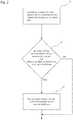
- the example method of controlling the fluid ejection device 2 of the three dimensional printing system 1 illustrated in Fig. 2provides prevention from clogging of the fluid ejection device's nozzles 5, e.g. in situations when the fluid ejection device 2 unintentionally stops in the hot area 6 above the (hot) build area 3.
- the memory of the fluid ejection device controller 11includes executable instructions that when executed by the processor of the fluid ejection device controller 11 causes the fluid ejection device controller 11 to perform the example method illustrated in Fig. 2 .
- the example methodincludes controlling, in block 21, by the controller 11, a motion of the fluid ejection device 2 to print agent onto the layer of build material 4 while crossing the build area 3. This corresponds to a regular printing stuation, for example.
- the example methodfurther includes detecting, in block 22, by the controller 11, whether an erroneous stopping of the motion of the fluid ejection device 2 has occurred and whether the fluid ejection device 2 is (actually) positioned on top of the build area 3 in the hot area 6. In the example method, these two conditions must be fulfilled in order to perform block 23 described below.
- the example methodfurther includes controlling, in block 23, by the controller 11, the fluid ejection device 2 to flush agent, e.g. through at least one nozzle 5, through all nozzles of a row of nozzles or through all nozzles of all rows of nozzles of the fluid ejection device 2.
- flushingis performed in response to detecting an erroneous stopping of the motion of the fluid ejection device and the fluid ejection device being positioned on top of the build area. This allows for preventing the fluid ejection device 2 from discharging agent within the hot area 6 on other parts of the three dimensional printing system 1 than the build area 3.
- Flushing agent through one or more nozzles 5 of the fluid ejection device 2causes a cooling effect on the fluid ejection device 2, e.g. by fresh cool agent entering the fluid ejection device 2 and by cooling down the surface of the build material layer 4 under the fluid ejection device 2 by agent discharged from the nozzles 5 when flashing.
- the example methodallows for increasing the life span of the fluid ejection device by overcoming the effects of system failure events by means avoiding the nozzle clogging in these circumstances.
- the flushing, in block 23,includes spitting agent by the nozzles 5 onto the build material layer 4.
- Spiting agentmeans discharging agent at low frequencies from one or more nozzles 5. This replaces old (wanned up) agent by fresh (cooler) agent from, e.g. retrieved from an agent cartridge.
- a main cooling effect of spitting agentis cooling down the build material layer 4 in the area of the fluid ejection device 2.
- the flushing in block 23,includes priming the fluid ejection device 2, for example. In priming the fluid ejection device 2 the throughput of agent through the fluid ejection device 2 (and the nozzles 5) is higher than with spitting agent.
- agentincreases the cooling effect as more fresh (cool) agent is passed to the fluid ejection device 2. Also more agent is discharged onto the build material layer 4 by priming, which therefore cools down even faster.
- the primingis performed by applying an air pressure to the agent system to blow out agent through the nozzles 5. This reduces or avoids self-heating of the fluid ejection device 2 during flushing.
- Controlling, in block 23, the fluid ejection device 2 to flush agent through the nozzlesis accompanied with a consumption of fresh agent obtained from a reservoir, e.g. the agent cartridge.
- the fluid ejection device 2is controlled, by the fluid ejection device controller 11, to spit, in block 23, (only) a certain quantity of agent, for example.
- the fluid ejection device 2is controlled, by the controller 11, to perform, in block 23, priming for a certain period of time (only).
- Agent consumption for flushingcan be further controlled in that only a single nozzle, only some of the nozzles or all nozzles 5 are flushed at a time.
Landscapes
- Chemical & Material Sciences (AREA)
- Engineering & Computer Science (AREA)
- Materials Engineering (AREA)
- Manufacturing & Machinery (AREA)
- Physics & Mathematics (AREA)
- Mechanical Engineering (AREA)
- Optics & Photonics (AREA)
Description
- Some three dimensional printing systems print three-dimensional objects by printing agent onto a layer of build material and heating the build material layer whereby the particles of build material moistened with agent fuse. The document
EP 2 955 004 A1 shows an example of unclogging an additive manufacturing system for forming a 3D component. - Examples will be described, by way of example only, with reference to the accompanying drawings in which corresponding reference numerals indicate corresponding parts and in which:
Figure 1 is an illustration of a three dimensional printing system with a fluid ejection device to print agent onto a build material layer on a build area in a hot area of the three dimensional printing system; andFigure 2 shows a block diagram of an example method for controlling the fluid ejection device of the three dimensional printing system.- Moreover the drawings provide examples and/or implementations consistent with the description; however, the description is not limited to the examples and/or implementations provided in the drawings.
- A three dimensional printing system according to claim 1 and a method of controlling a fluid ejection device according to claim 9 are provided. Examples thereof are detailed in the dependent claims. The description refers to controlling a fluid ejection device, of which, some examples may be referred to as 3D printer. The description further refers to a fluid ejection device controller and to a three dimensional printing system.
- An example three dimensional printing system prints an agent onto a layer of build material in a build area of the printer. The printer heats the build material layer to fuse the particles of build material moistened by the agent, whereas non-moistened particles of build material remain unfused. This may be repeated multiple times layer by layer in that a further build material layer is deposited on top of a previous layer, agent is printed onto the further layer and this layer is heated to fuse the moistened particles of build material of this layer and so on. Thereby, a 3D object may be formed, i.e., printed by the three dimensional printing system.
- Temperatures in the area of the build area may be high, as, for example, the fusing of the build material is performed by heating. While regularly printing, high temperatures in the area of the build area are less problematic for the fluid ejection device, because the short times spent above the build area. However, for example, a system failure of the printer may occur leaving the fluid ejection device stopped on top of the hot build area, which, for example, has temperatures higher than 150° C. Staying, e.g. more than one minute, on top of the hot build area and close to it, e.g. around 3 mm above a surface of a topmost build material layer, may dry out the agent at the nozzles and clog them. Even worse, the high temperature may push the fluid ejection device surface temperature beyond a boiling point of the agent and boil agent inside the nozzles and adjacent fluidics.
- The claimed method of controlling the fluid ejection device of the three dimensional printing system includes controlling a motion of the fluid ejection device to print agent onto the (topmost) layer of build material in the build area. Controlling the fluid ejection device further includes flushing agent through at least one nozzle of the fluid ejection device in response to detecting an erroneous stopping of the motion of the fluid ejection device and the fluid ejection device being positioned on top of the build area (i.e. the step of flushing agent is carried out when both conditions are fulfilled at the same time).
- The claimed method may prevent from clogging of the fluid ejection device's nozzles in situations when the fluid ejection device unintentionally stops in an area of the build area. Flushing agent through one or more nozzles of the fluid ejection device may produce a cooling effect on the fluid ejection device, e.g. by fresh cool agent entering the fluid ejection device and/or by cooling down the surface of the build material under the fluid ejection device by agent discharged from the nozzles when flushing. Flushing agent when the fluid ejection device is positioned on top of the build area prevents from the fuild ejection device dispensing agent on other members than the build area that may not be prepared for it. For example, the surface of the build material under the fluid ejection device is cooled down from the bed temperature to a temperature that reduces the agent evaporation to normal levels. The example method allows for increasing the life span of the fluid ejection device by overcoming the effects of system failure events by means avoiding the nozzle clogging in these circumstances.
- For example, the agent includes an agent, e.g. to solidify or color particles of build material moistened with agent. For example, the agent includes one or more of, e.g, a fusing agent, a binding agent, a detailing agent, a coloring agent and/or a conductivity changing agent.
- In some examples, the agent includes the binding agent to stick together particles of build material By heating the build material layer the curing process is accelerated to reduce or avoid any waiting times before printing the next layer, for example. In some examples, the build area is heated up to temperatures of at least 80° C, 100° C, 120° C or 150° C. To avoid degradation of the build material, in some embodiments the temperature of the build material layer is controlled to not exceed 130° C, 160° C, 180° C or 200° C.
- In some examples, the agent includes the fusing agent with (high) infrared (IR) absorption capacity. This allows for sintering, ie. melting together particles of build material moistened with agent by applying (e.g. from an IR light source) heat radiation to the build material layer. The fusing agent highly absorbs the heat radiation thereby heating up the agent moistened particles of build material above their melting point, whereas non-moistened particles of build material absorb less heat radiation and do not reach their melting point.
- In some examples, flushing includes spitting, ie. controlling the fluid ejection device to dispense agent by one or more nozzles at a reasonably low frequency. Spitting agent onto the surface of the build material layer cools down the build material layer. This reduces heating of the fluid ejection device by heat originating from the build material layer. Spitting may be performed by the same technique as usually printing agent is performed by the fluid ejection device. Spitting also reduces clogging by replacing the drying agent in the nozzles by fresh agent. Furthermore, spitting agent dispenses (heated up) agent from the fluid ejection device and, thereby, transports away heat from the print head. However, in some printing techniques, e.g. thermal printing the spitting heats up the fluid ejection device, i.e. spitting may cause self-heating of the fluid ejection device. In such situations, cooling down the build area is the main cooling effect of spitting agent, for example.
- In some examples, flushing includes priming the fluid ejection device. For example, priming includes pressurizing an agent reservoir and pumping agent under pressure through the fluid ejection device out of the nozzles. Like spitting, also priming dispenses (heated up) agent from the fluid ejection device and let (colder) fresh agent flow to the fluid ejection device from the agent reservoir to transport away heat from the print bead. Flushing the fluid ejection device by priming may achieve a higher throughput of agent through the fluid ejection device and, thereby, achieving a stronger cooling effect in comparison with spitting Also priming cools down the build material layer by flushing the agent from the fluid ejection device onto the surface of the build material layer. The priming does not heat up the fluid ejection device. For example, the fluid ejection device can be (electrically) shut down for flushing to reduce the self-heating of the fluid ejection device.
- In some examples, the fluid ejection device may be controlled to spit a certain quantity of agent. In some examples, the fluid ejection device may be controlled to perform priming for a certain period of time. This allows for not to use up all the agent in the agent reservoir at a system failure event.
- To reduce clogging of the nozzles and/or for a maximum throughput of agent, in some examples, all nozzles of the fluid ejection device are flushed. For example, some or all nozzles of the print head are flushed in turn. This enables a more continuous beat transport away from the fluid ejection device while keeping the quantity of the flushed agent lower than when (continuously) flushing all nozzles in parallel. To increase the cooling effect, in some examples the fluid ejection device is controlled to flush agent with two or more or even all nozzles at the same time. In some examples, the fluid ejection device is controlled to increase the frequency of spitting agent to increase the cooling effect.
- In some examples, the three dimensional printing system is equipped with a position detector to detect whether the fluid ejection device is located in the area, e.g. on top, of the build area. In some examples, the flushing agent through the fluid ejection device is only carried out, if the position of the fluid ejection device is detected to be on top of the build area. This protects the three dimensional printing system to be contaminated with agent at other places than the build area in system failure situations when the fluid ejection device unintentionally stops, e.g. outside a parking position for the fluid ejection device.
- In some examples, the internal of the three dimensional printing system e.g. the area of the build area, is also cooled by a (further) cooling system. For example, the internal of the three dimensional printing system is vented by cool environmental air. This can reduce the heating up of the stopped fluid ejection device and also reduce the quantity of agent to be flushed through the fluid ejection device for cooling the fluid ejection device.
- Now referring to
Fig. 1 , an example three dimensional printing system 1 to print three dimensional objects has and a fluid ejection device 2 to print agent onto a layer of build material 4 in abuild area 3. The three dimensional printing system further has a fluidejection device controller 11 for controlling the fluid ejection device 2. The fluidejection device controller 11 is equipped with aprocessor 12 and amemory 13, thememory 13 includes executable instructions that when executed by theprocessor 12 causes the fluidejection device controller 11 to control a motion of the fluid ejection device 2 to print agent onto the layer of build material 4 in abuild area 3. - The example three dimensional printing system 1 generates 3D objects in a layer wise manner, wherein each layer represents a cross-section at a particular height of the 3D object to be printed. To generate the 3D object, the three dimensional printing system 1 prints a cross-sectional image corresponding to a certain height-level of the 3D object to be printed onto the build material layer 4. Particles of build material onto which agent is printed (ie. which are moistened with agent) agglomerate. Then a further layer of build material is provided on top of the previous layer of build material and the printer 1 prints a further cross-sectional image corresponding to a next height-level of the 3D object to be printed onto this further layer. This enables the three dimensional printing system 1 to print 3D objects layer by layer - so to say the object to be printed grows up from the
build area 3. The printed 3D object is built of agglomerated particles of build material which are embedded in surrounding loose particles of build material on which no agent has been printed. Removing the loose particles of build material e.g. by brushing or blowing, leaves the desired 3D object. - A respective cross-sectional image of the 3D object is printed by discharging agent from
nozzles 5 of the fluid ejection device 2 while moving the fluid ejection device 2 over thebuild area 3 with the build material layer 4. The fluid ejection device 2 has at least one row ofnozzles 5 to print a swath of agent each time the fluid ejection device 2 crosses thebuild area 3. For example, the fluid ejection device 2 has two. three or four rows ofnozzles 5. In some examples, a first row ofnozzles 5 is for printing a first agent and a second row ofnozzles 5 is for printing a second agent. In some examples, the fluid ejection device 2 has a third row ofnozzles 5 to print a third agent and, in some of these examples, the fluid ejection device 2 has a fourth row ofnozzles 5 to print a fourth agent. - In some examples, the three dimensional printing system is a scanning type printer, ie. an image is printed onto a build material layer by printing several swaths, e.g. by performing (controlled by the fluid ejection device controller 11) a scanning like back and forth motion of the fluid ejection device while moving the build area in a direction transverse to the back and forth motion of the fluid ejection device after printing a swath. This allows for printing 3D objects having a minimum cross-sectional diameter larger than the length of the row of nozzles of the fluid ejection device.
- In some examples, the three dimensional printing system is a page wide printer, i.e. the length of the row of nozzles has a length which corresponds to a maximum cross-sectional diameter of printable 3D objects in a direction transverse to the back and forth motion of the fluid ejection device. This allows for fast 3D printing, since the fluid ejection device can print a complete cross-sectional image onto the build material layer by a single motion crossing the build area.
- Turning back to the example illustrated in
Fig. 1 , the three dimensional printing system 1 has a bot area 6 arranged between adjacent oppositecold areas 7. For example, (controlled by the fluid ejection device controller 11) during printing the fluid ejection device 2 performs a back and forth motion from onecold area 7 to the other (opposite) cold area 7 (and vice-versa) traversing the hot area 6 and, thereby, crossing the area of thebuild area 3 arranged in the bot area 6 to print agent onto the (topmost) build material layer 4. Apre-heater 8 is arranged in the bot area 6 to heat up thebuild area 3 and the build material layer 4 to a certain (pre-heating) temperature. For example, thepre-heater 8 has a resistor heating element or an IR light source to heat the bot area 6. However, to not innecessarily degrade the build material on thebuild area 3, pre-heating heats up thebuild area 3 and the build material layer 4 to (pre-heating) temperatures below a working temperature, ie. a temperature at which the agglomeration of agented particles of build material efficiently performs. - To heat up the (topmost) build material layer 4 to the working temperature, the fluid ejection device 2 is equipped with one or two or
multiple heaters 10 for locally heating the build material layer 4 immediately before or immediately after or immediately before and after printing agent onto the build material layer 4. In some examples, the heater(s) are mounted at a carriage, which also carries the fluid ejection device 2. For example, one ormultiple heaters 10 are arranged at either side of the fluid ejection device 2 with regard to the direction of the back and forth motion of the fluid ejection device 2. Using these heater(s) 10, which travel with the fluid ejection device 2, the build material layer 4 is momentarily heated up to the working temperature for agglomerating the particles of build material moistened with agent Pre-heating the build material layer 4 supports the agglomeration of the particles of build material in that the required temperature step to heat up the build material layer 4 to the working temperature by the heater(s) 10 can be reduced. This allows for faster printing, for example. - For example, the agent includes one or more agents, e.g. a fusing agent, a binding agent, a detailing agent, a coloring agent and/or a conductivity changing agent.
- The fusing agent has a higher infrared (IR) absorption capacity than the particles of build material. When the three dimensional printing system 1 applies heat radiation, e.g. by the heater(s) 10, onto the build material layer 4 and the particles of build material moistened with the fusing agent beat up to higher temperatures as particles of build material not moistened with the fusing agent, as the fusing agent absorbs more beat radiation than the (pure) particles of build material This allows for heating up the moistened particles of build material to a working temperature above their melting point and, thereby, melting them together, whereas non-moistened particles of build material stay below their melting point and do not agglomerate.
- As to the binding agent, particles of build material on which agent has been printed are, thus, moistened with the binding agent. This binding agent hardens (in short time) when exposed to the working temperature and, thereby, clues together that particles of build material onto which agent has been printed. 3D objects can be printed by the three dimensional priding system 1 in that the three dimensional printing system 1 prints cross-sectional structures of the desired 3D object onto the build material layer 4, wherein the particles of build material moistened by the agent solidify under heat.
- Exposing the fluid ejection device 2 to high temperatures heats up the fluid ejection device 2 and can reduce its lifetime. For example, the agent in the fluid ejection device 2, in particular in the
nozzles 5, may dry or boil if the fluid ejection device 2 is heated up to too high temperatures. In regular prating operation, the fluid ejection device 2 resides in the hot area 6 for short periods of times only, namely while moving from onecold area 7 to the othercold area 7 and thereby crossing the hot area 6 to print agent onto the build material layer 2. This prevents the fluid ejection device 2 from overbeating in regular operation. For example, one of thecold areas 7 or bothcold areas 7 are equipped with a parking assembly 9 to cover thenozzles 5, e.g. to protect them from drying out. For example, in time periods between printing different 3D objects and/or while applying a new or further build material layer onto thebuild area 3, the fluid ejection device 2 stays in (one of) thecold areas 7 and rests at the parking assembly 9. In thecold areas 7 thefluid ejection device 7 can stay at non-critical temperatures or can cool down after having visited the hot area 6. - Therefore, in a regular printing situation, high temperatures in the hot area 6 are less problematic for the fluid ejection device 2, because the short times spent in the hot area 6, in particular above the
hot build area 3. However, for example, a system failure of the three dimensional printing system 1 may occur leaving the fluid ejection device 2 unintentionally stopped in the hot area 6. Staying there may dry out the agent in thenozzles 5 and clog them - The example method of controlling the fluid ejection device 2 of the three dimensional printing system 1 illustrated in
Fig. 2 provides prevention from clogging of the fluid ejection device'snozzles 5, e.g. in situations when the fluid ejection device 2 unintentionally stops in the hot area 6 above the (hot)build area 3. The memory of the fluidejection device controller 11 includes executable instructions that when executed by the processor of the fluidejection device controller 11 causes the fluidejection device controller 11 to perform the example method illustrated inFig. 2 . - The example method includes controlling, in
block 21, by thecontroller 11, a motion of the fluid ejection device 2 to print agent onto the layer of build material 4 while crossing thebuild area 3. This corresponds to a regular printing stuation, for example. - The example method further includes detecting, in
block 22, by thecontroller 11, whether an erroneous stopping of the motion of the fluid ejection device 2 has occurred and whether the fluid ejection device 2 is (actually) positioned on top of thebuild area 3 in the hot area 6. In the example method, these two conditions must be fulfilled in order to performblock 23 described below. - The example method further includes controlling, in
block 23, by thecontroller 11, the fluid ejection device 2 to flush agent, e.g. through at least onenozzle 5, through all nozzles of a row of nozzles or through all nozzles of all rows of nozzles of the fluid ejection device 2. - Therefore, flushing is performed in response to detecting an erroneous stopping of the motion of the fluid ejection device and the fluid ejection device being positioned on top of the build area. This allows for preventing the fluid ejection device 2 from discharging agent within the hot area 6 on other parts of the three dimensional printing system 1 than the
build area 3. - Flushing agent through one or
more nozzles 5 of the fluid ejection device 2 causes a cooling effect on the fluid ejection device 2, e.g. by fresh cool agent entering the fluid ejection device 2 and by cooling down the surface of the build material layer 4 under the fluid ejection device 2 by agent discharged from thenozzles 5 when flashing. The example method allows for increasing the life span of the fluid ejection device by overcoming the effects of system failure events by means avoiding the nozzle clogging in these circumstances. - For example, the flushing, in
block 23, includes spitting agent by thenozzles 5 onto the build material layer 4. Spiting agent means discharging agent at low frequencies from one ormore nozzles 5. This replaces old (wanned up) agent by fresh (cooler) agent from, e.g. retrieved from an agent cartridge. For example, a main cooling effect of spitting agent is cooling down the build material layer 4 in the area of the fluid ejection device 2. For a higher cooling effect, the flushing inblock 23, includes priming the fluid ejection device 2, for example. In priming the fluid ejection device 2 the throughput of agent through the fluid ejection device 2 (and the nozzles 5) is higher than with spitting agent. The higher throughput of agent increases the cooling effect as more fresh (cool) agent is passed to the fluid ejection device 2. Also more agent is discharged onto the build material layer 4 by priming, which therefore cools down even faster. For example, the priming is performed by applying an air pressure to the agent system to blow out agent through thenozzles 5. This reduces or avoids self-heating of the fluid ejection device 2 during flushing. - Controlling, in
block 23, the fluid ejection device 2 to flush agent through the nozzles is accompanied with a consumption of fresh agent obtained from a reservoir, e.g. the agent cartridge. To avoid an undue high consumption of agent, the fluid ejection device 2 is controlled, by the fluidejection device controller 11, to spit, inblock 23, (only) a certain quantity of agent, for example. For the same reason, in some examples, the fluid ejection device 2 is controlled, by thecontroller 11, to perform, inblock 23, priming for a certain period of time (only). Agent consumption for flushing can be further controlled in that only a single nozzle, only some of the nozzles or allnozzles 5 are flushed at a time. - Although some examples of methods and products have been described herein, other variations are generally within the scope of this description. As will be appreciated, the description generally contemplates various implementations fairly falling within the scope of the appended claims.
Claims (9)
- A three dimensional printing system (1) comprising:a fluid ejection device (2); anda fluid ejection device controller (11) for controlling the fluid ejection device (2) of the three dimensional printing system (1), the fluid ejection device controller (11) comprising a processor (12) and a memory (13), the memory (13) comprises executable instructions that when executed by the processor (12) causes the fluid ejection device controller (11) tocontrol a motion of the fluid ejection device (2) to print agent onto a layer of build material (4) in a build area (3); andto flush agent through at least one nozzle (5) of the fluid ejection device (2) in response to detecting, by the fluid ejection device controller (11), an erroneous stopping of the motion of the fluid ejection device (2) and the fluid ejection device (2) being positioned on top of the build area (3).
- A three dimensional printing system (1) according to claim 1, wherein the agent comprises at least one of a fusing agent, a binding agent, a detailing agent, a coloring agent and a conductivity changing agent.
- A three dimensional printing system (1) (11) according to claim 1, wherein to flush agent comprises to spit agent.
- A three dimensional printing system (1) according to claim 3, wherein to spit agent comprises to spit a certain quantity of agent.
- A three dimensional printing system (1) according to claim 1, wherein to flush agent comprises to prime the fluid ejection device (2).
- A three dimensional printing system (1) according to claim 5, wherein to prime the fluid ejection device (2) comprises to prime the fluid ejection device (2) for a certain period of time.
- A three dimensional printing system (1) according to claim 1, wherein the fluid ejection device (2) comprises at least one row of nozzles (5).
- A three dimensional printing system (1) according to claim 7, wherein to flush agent comprises to flush agent through all nozzles (5) of the fluid ejection device (2).
- A method of controlling a fluid ejection device (2) of a three dimensional printing system (1);
the method comprising:controlling a motion of the fluid ejection device (2) to print agent onto a layer of build material (4) in a build area (3); andin response to detecting an erroneous stopping of the motion of the fluid ejection device (2) and the fluid ejection device (2) being positioned on top of the build area (3), flushing agent through at least one nozzle (5) of the fluid ejection device (2).
Applications Claiming Priority (1)
| Application Number | Priority Date | Filing Date | Title |
|---|---|---|---|
| PCT/US2016/057722WO2018075031A1 (en) | 2016-10-19 | 2016-10-19 | Flushing a fluid ejection device |
Publications (3)
| Publication Number | Publication Date |
|---|---|
| EP3468776A1 EP3468776A1 (en) | 2019-04-17 |
| EP3468776A4 EP3468776A4 (en) | 2020-04-22 |
| EP3468776B1true EP3468776B1 (en) | 2021-06-09 |
Family
ID=62019623
Family Applications (1)
| Application Number | Title | Priority Date | Filing Date |
|---|---|---|---|
| EP16919008.9AActiveEP3468776B1 (en) | 2016-10-19 | 2016-10-19 | Flushing a fluid ejection device |
Country Status (4)
| Country | Link |
|---|---|
| US (1) | US10987864B2 (en) |
| EP (1) | EP3468776B1 (en) |
| CN (1) | CN110087865B (en) |
| WO (1) | WO2018075031A1 (en) |
Family Cites Families (19)
| Publication number | Priority date | Publication date | Assignee | Title |
|---|---|---|---|---|
| US5594652A (en)* | 1991-01-31 | 1997-01-14 | Texas Instruments Incorporated | Method and apparatus for the computer-controlled manufacture of three-dimensional objects from computer data |
| US6523932B2 (en) | 2001-01-14 | 2003-02-25 | Hewlett-Packard Company | Periodic ejection of printing fluid to service orifices of an inkjet printer |
| AU2003900180A0 (en)* | 2003-01-16 | 2003-01-30 | Silverbrook Research Pty Ltd | Method and apparatus (dam001) |
| US7306758B2 (en) | 2003-03-13 | 2007-12-11 | Hewlett-Packard Development Company, L.P. | Methods and systems for controlling printhead temperature in solid freeform fabrication |
| US8916794B2 (en) | 2003-03-28 | 2014-12-23 | Japan Science And Technology Agency | Metal jet apparatus and jet method |
| US8033811B2 (en) | 2008-07-25 | 2011-10-11 | Stratasys, Inc. | Pantograph assembly for digital manufacturing system |
| US8128188B2 (en) | 2009-04-30 | 2012-03-06 | Hewlett-Packard Development Company, L.P. | Monitoring ink flow |
| JP2013067016A (en) | 2011-09-20 | 2013-04-18 | Keyence Corp | Three-dimensional shaping apparatus |
| US9162453B2 (en) | 2012-07-30 | 2015-10-20 | Hewlett-Packard Development Company, L.P. | Printhead including integrated circuit die cooling |
| DE102013004940A1 (en) | 2012-10-15 | 2014-04-17 | Voxeljet Ag | Method and device for producing three-dimensional models with tempered printhead |
| US9085109B2 (en)* | 2013-11-15 | 2015-07-21 | Makerbot Industries, Llc | Three-dimensional printer tool systems |
| US9415600B2 (en) | 2014-03-31 | 2016-08-16 | Xerox Corporation | System for detecting inoperative inkjets in three-dimensional object printing using a digital camera and strobe light |
| CN105313332B (en) | 2014-06-09 | 2020-05-05 | 联合工艺公司 | Two-part thermosetting resin additive manufacturing system |
| CN104190664B (en) | 2014-08-04 | 2016-05-11 | 深圳光华伟业股份有限公司 | A kind of cleaning method of nozzle of FDM-3D printer and cleaning lines |
| US9833950B2 (en) | 2014-10-01 | 2017-12-05 | Xerox Corporation | System and method for inoperative inkjet detection in a printer of three-dimensional objects |
| CN104290325B (en) | 2014-10-09 | 2017-10-13 | 芜湖林一电子科技有限公司 | A kind of surplus material of 3 D-printing system is reclaimed and shower nozzle cleaning method |
| CN204149546U (en) | 2014-10-31 | 2015-02-11 | 成都美律科技有限公司 | A kind of 3D printer with temperature control |
| CN105252770B (en)* | 2015-11-10 | 2018-04-03 | 珠海天威飞马打印耗材有限公司 | 3 D-printing method and three-dimensional printer |
| CN105856572A (en) | 2016-05-11 | 2016-08-17 | 中山市东方博达电子科技有限公司 | Device and method for automatic positioning and fault detection of light-curing 3D printer |
- 2016
- 2016-10-19CNCN201680088597.7Apatent/CN110087865B/ennot_activeExpired - Fee Related
- 2016-10-19EPEP16919008.9Apatent/EP3468776B1/enactiveActive
- 2016-10-19USUS16/315,261patent/US10987864B2/ennot_activeExpired - Fee Related
- 2016-10-19WOPCT/US2016/057722patent/WO2018075031A1/ennot_activeCeased
Non-Patent Citations (1)
| Title |
|---|
| None* |
Also Published As
| Publication number | Publication date |
|---|---|
| US10987864B2 (en) | 2021-04-27 |
| CN110087865B (en) | 2021-06-18 |
| CN110087865A (en) | 2019-08-02 |
| EP3468776A4 (en) | 2020-04-22 |
| US20190240910A1 (en) | 2019-08-08 |
| EP3468776A1 (en) | 2019-04-17 |
| WO2018075031A1 (en) | 2018-04-26 |
Similar Documents
| Publication | Publication Date | Title |
|---|---|---|
| CN109070467B (en) | Definition of protective features for additive manufacturing | |
| CA3014150A1 (en) | Movable printing devices for three-dimensional printers | |
| JP2009196208A (en) | Inkjet printer | |
| US8878883B2 (en) | Inkjet printer having an image drum heating and cooling system | |
| EP0333819A1 (en) | Platen arrangement for hot melt ink jet apparatus | |
| JP2011020318A (en) | Inkjet recording device and recording method thereof | |
| JP2013022845A (en) | Nozzle surface cleaning device and droplet ejection apparatus | |
| JP2012045764A (en) | Image recording device, and drying control method | |
| US20130328983A1 (en) | Inkjet Printer having an Image Drum Heater with Heater Seals | |
| JP6080418B2 (en) | Inkjet recording device | |
| JPH1086353A (en) | Ink jet recording device | |
| JP7631406B2 (en) | Printing device and printing method | |
| JP2008037020A (en) | Ink temperature adjusting mechanism, image recording device, ink temperature adjusting method and program | |
| EP3468776B1 (en) | Flushing a fluid ejection device | |
| TWI689405B (en) | Apparatus for generating a three-dimensional object and method therefor | |
| CN107848196A (en) | Print the distribution of reagent | |
| US20170210155A1 (en) | Liquid droplet ejecting apparatus | |
| US8845065B2 (en) | Inkjet printer having an image drum heater and cooler | |
| US7475973B2 (en) | Sheet handling device with a temperature controlled sheet support plate | |
| JP2003220714A (en) | Inkjet printer | |
| JP2008284883A (en) | Ink-jet recorder | |
| EP3934892B1 (en) | Reducing caking of build material | |
| JP2009012480A (en) | Inkjet recording device | |
| JP5729966B2 (en) | Recording device | |
| JPH11221914A (en) | Inkjet printing equipment |
Legal Events
| Date | Code | Title | Description |
|---|---|---|---|
| STAA | Information on the status of an ep patent application or granted ep patent | Free format text:STATUS: THE INTERNATIONAL PUBLICATION HAS BEEN MADE | |
| PUAI | Public reference made under article 153(3) epc to a published international application that has entered the european phase | Free format text:ORIGINAL CODE: 0009012 | |
| STAA | Information on the status of an ep patent application or granted ep patent | Free format text:STATUS: REQUEST FOR EXAMINATION WAS MADE | |
| 17P | Request for examination filed | Effective date:20190110 | |
| AK | Designated contracting states | Kind code of ref document:A1 Designated state(s):AL AT BE BG CH CY CZ DE DK EE ES FI FR GB GR HR HU IE IS IT LI LT LU LV MC MK MT NL NO PL PT RO RS SE SI SK SM TR | |
| AX | Request for extension of the european patent | Extension state:BA ME | |
| RAP1 | Party data changed (applicant data changed or rights of an application transferred) | Owner name:HEWLETT-PACKARD DEVELOPMENT COMPANY, L.P. | |
| DAV | Request for validation of the european patent (deleted) | ||
| DAX | Request for extension of the european patent (deleted) | ||
| A4 | Supplementary search report drawn up and despatched | Effective date:20200319 | |
| RIC1 | Information provided on ipc code assigned before grant | Ipc:B33Y 40/00 20200101ALI20200313BHEP Ipc:B29C 64/386 20170101ALI20200313BHEP Ipc:B29C 64/165 20170101ALI20200313BHEP Ipc:B29C 64/35 20170101AFI20200313BHEP Ipc:B29C 64/112 20170101ALI20200313BHEP | |
| STAA | Information on the status of an ep patent application or granted ep patent | Free format text:STATUS: EXAMINATION IS IN PROGRESS | |
| 17Q | First examination report despatched | Effective date:20200903 | |
| GRAP | Despatch of communication of intention to grant a patent | Free format text:ORIGINAL CODE: EPIDOSNIGR1 | |
| STAA | Information on the status of an ep patent application or granted ep patent | Free format text:STATUS: GRANT OF PATENT IS INTENDED | |
| INTG | Intention to grant announced | Effective date:20210120 | |
| GRAJ | Information related to disapproval of communication of intention to grant by the applicant or resumption of examination proceedings by the epo deleted | Free format text:ORIGINAL CODE: EPIDOSDIGR1 | |
| STAA | Information on the status of an ep patent application or granted ep patent | Free format text:STATUS: EXAMINATION IS IN PROGRESS | |
| INTC | Intention to grant announced (deleted) | ||
| GRAP | Despatch of communication of intention to grant a patent | Free format text:ORIGINAL CODE: EPIDOSNIGR1 | |
| STAA | Information on the status of an ep patent application or granted ep patent | Free format text:STATUS: GRANT OF PATENT IS INTENDED | |
| GRAS | Grant fee paid | Free format text:ORIGINAL CODE: EPIDOSNIGR3 | |
| INTG | Intention to grant announced | Effective date:20210409 | |
| GRAA | (expected) grant | Free format text:ORIGINAL CODE: 0009210 | |
| STAA | Information on the status of an ep patent application or granted ep patent | Free format text:STATUS: THE PATENT HAS BEEN GRANTED | |
| AK | Designated contracting states | Kind code of ref document:B1 Designated state(s):AL AT BE BG CH CY CZ DE DK EE ES FI FR GB GR HR HU IE IS IT LI LT LU LV MC MK MT NL NO PL PT RO RS SE SI SK SM TR | |
| REG | Reference to a national code | Ref country code:GB Ref legal event code:FG4D | |
| REG | Reference to a national code | Ref country code:CH Ref legal event code:EP Ref country code:AT Ref legal event code:REF Ref document number:1400106 Country of ref document:AT Kind code of ref document:T Effective date:20210615 | |
| REG | Reference to a national code | Ref country code:DE Ref legal event code:R096 Ref document number:602016059262 Country of ref document:DE | |
| REG | Reference to a national code | Ref country code:IE Ref legal event code:FG4D | |
| REG | Reference to a national code | Ref country code:LT Ref legal event code:MG9D | |
| PG25 | Lapsed in a contracting state [announced via postgrant information from national office to epo] | Ref country code:FI Free format text:LAPSE BECAUSE OF FAILURE TO SUBMIT A TRANSLATION OF THE DESCRIPTION OR TO PAY THE FEE WITHIN THE PRESCRIBED TIME-LIMIT Effective date:20210609 Ref country code:LT Free format text:LAPSE BECAUSE OF FAILURE TO SUBMIT A TRANSLATION OF THE DESCRIPTION OR TO PAY THE FEE WITHIN THE PRESCRIBED TIME-LIMIT Effective date:20210609 Ref country code:BG Free format text:LAPSE BECAUSE OF FAILURE TO SUBMIT A TRANSLATION OF THE DESCRIPTION OR TO PAY THE FEE WITHIN THE PRESCRIBED TIME-LIMIT Effective date:20210909 Ref country code:HR Free format text:LAPSE BECAUSE OF FAILURE TO SUBMIT A TRANSLATION OF THE DESCRIPTION OR TO PAY THE FEE WITHIN THE PRESCRIBED TIME-LIMIT Effective date:20210609 | |
| PGFP | Annual fee paid to national office [announced via postgrant information from national office to epo] | Ref country code:FR Payment date:20210921 Year of fee payment:6 | |
| REG | Reference to a national code | Ref country code:AT Ref legal event code:MK05 Ref document number:1400106 Country of ref document:AT Kind code of ref document:T Effective date:20210609 | |
| REG | Reference to a national code | Ref country code:NL Ref legal event code:MP Effective date:20210609 | |
| PG25 | Lapsed in a contracting state [announced via postgrant information from national office to epo] | Ref country code:LV Free format text:LAPSE BECAUSE OF FAILURE TO SUBMIT A TRANSLATION OF THE DESCRIPTION OR TO PAY THE FEE WITHIN THE PRESCRIBED TIME-LIMIT Effective date:20210609 Ref country code:GR Free format text:LAPSE BECAUSE OF FAILURE TO SUBMIT A TRANSLATION OF THE DESCRIPTION OR TO PAY THE FEE WITHIN THE PRESCRIBED TIME-LIMIT Effective date:20210910 Ref country code:NO Free format text:LAPSE BECAUSE OF FAILURE TO SUBMIT A TRANSLATION OF THE DESCRIPTION OR TO PAY THE FEE WITHIN THE PRESCRIBED TIME-LIMIT Effective date:20210909 Ref country code:SE Free format text:LAPSE BECAUSE OF FAILURE TO SUBMIT A TRANSLATION OF THE DESCRIPTION OR TO PAY THE FEE WITHIN THE PRESCRIBED TIME-LIMIT Effective date:20210609 Ref country code:RS Free format text:LAPSE BECAUSE OF FAILURE TO SUBMIT A TRANSLATION OF THE DESCRIPTION OR TO PAY THE FEE WITHIN THE PRESCRIBED TIME-LIMIT Effective date:20210609 | |
| PGFP | Annual fee paid to national office [announced via postgrant information from national office to epo] | Ref country code:GB Payment date:20210922 Year of fee payment:6 | |
| PG25 | Lapsed in a contracting state [announced via postgrant information from national office to epo] | Ref country code:EE Free format text:LAPSE BECAUSE OF FAILURE TO SUBMIT A TRANSLATION OF THE DESCRIPTION OR TO PAY THE FEE WITHIN THE PRESCRIBED TIME-LIMIT Effective date:20210609 Ref country code:CZ Free format text:LAPSE BECAUSE OF FAILURE TO SUBMIT A TRANSLATION OF THE DESCRIPTION OR TO PAY THE FEE WITHIN THE PRESCRIBED TIME-LIMIT Effective date:20210609 Ref country code:AT Free format text:LAPSE BECAUSE OF FAILURE TO SUBMIT A TRANSLATION OF THE DESCRIPTION OR TO PAY THE FEE WITHIN THE PRESCRIBED TIME-LIMIT Effective date:20210609 Ref country code:ES Free format text:LAPSE BECAUSE OF FAILURE TO SUBMIT A TRANSLATION OF THE DESCRIPTION OR TO PAY THE FEE WITHIN THE PRESCRIBED TIME-LIMIT Effective date:20210609 Ref country code:RO Free format text:LAPSE BECAUSE OF FAILURE TO SUBMIT A TRANSLATION OF THE DESCRIPTION OR TO PAY THE FEE WITHIN THE PRESCRIBED TIME-LIMIT Effective date:20210609 Ref country code:PT Free format text:LAPSE BECAUSE OF FAILURE TO SUBMIT A TRANSLATION OF THE DESCRIPTION OR TO PAY THE FEE WITHIN THE PRESCRIBED TIME-LIMIT Effective date:20211011 Ref country code:NL Free format text:LAPSE BECAUSE OF FAILURE TO SUBMIT A TRANSLATION OF THE DESCRIPTION OR TO PAY THE FEE WITHIN THE PRESCRIBED TIME-LIMIT Effective date:20210609 Ref country code:SK Free format text:LAPSE BECAUSE OF FAILURE TO SUBMIT A TRANSLATION OF THE DESCRIPTION OR TO PAY THE FEE WITHIN THE PRESCRIBED TIME-LIMIT Effective date:20210609 Ref country code:SM Free format text:LAPSE BECAUSE OF FAILURE TO SUBMIT A TRANSLATION OF THE DESCRIPTION OR TO PAY THE FEE WITHIN THE PRESCRIBED TIME-LIMIT Effective date:20210609 | |
| PGFP | Annual fee paid to national office [announced via postgrant information from national office to epo] | Ref country code:DE Payment date:20210921 Year of fee payment:6 | |
| PG25 | Lapsed in a contracting state [announced via postgrant information from national office to epo] | Ref country code:PL Free format text:LAPSE BECAUSE OF FAILURE TO SUBMIT A TRANSLATION OF THE DESCRIPTION OR TO PAY THE FEE WITHIN THE PRESCRIBED TIME-LIMIT Effective date:20210609 | |
| REG | Reference to a national code | Ref country code:DE Ref legal event code:R097 Ref document number:602016059262 Country of ref document:DE | |
| PLBE | No opposition filed within time limit | Free format text:ORIGINAL CODE: 0009261 | |
| STAA | Information on the status of an ep patent application or granted ep patent | Free format text:STATUS: NO OPPOSITION FILED WITHIN TIME LIMIT | |
| PG25 | Lapsed in a contracting state [announced via postgrant information from national office to epo] | Ref country code:DK Free format text:LAPSE BECAUSE OF FAILURE TO SUBMIT A TRANSLATION OF THE DESCRIPTION OR TO PAY THE FEE WITHIN THE PRESCRIBED TIME-LIMIT Effective date:20210609 | |
| 26N | No opposition filed | Effective date:20220310 | |
| REG | Reference to a national code | Ref country code:CH Ref legal event code:PL | |
| PG25 | Lapsed in a contracting state [announced via postgrant information from national office to epo] | Ref country code:AL Free format text:LAPSE BECAUSE OF FAILURE TO SUBMIT A TRANSLATION OF THE DESCRIPTION OR TO PAY THE FEE WITHIN THE PRESCRIBED TIME-LIMIT Effective date:20210609 | |
| REG | Reference to a national code | Ref country code:BE Ref legal event code:MM Effective date:20211031 | |
| PG25 | Lapsed in a contracting state [announced via postgrant information from national office to epo] | Ref country code:MC Free format text:LAPSE BECAUSE OF FAILURE TO SUBMIT A TRANSLATION OF THE DESCRIPTION OR TO PAY THE FEE WITHIN THE PRESCRIBED TIME-LIMIT Effective date:20210609 | |
| PG25 | Lapsed in a contracting state [announced via postgrant information from national office to epo] | Ref country code:LU Free format text:LAPSE BECAUSE OF NON-PAYMENT OF DUE FEES Effective date:20211019 Ref country code:IT Free format text:LAPSE BECAUSE OF FAILURE TO SUBMIT A TRANSLATION OF THE DESCRIPTION OR TO PAY THE FEE WITHIN THE PRESCRIBED TIME-LIMIT Effective date:20210609 Ref country code:BE Free format text:LAPSE BECAUSE OF NON-PAYMENT OF DUE FEES Effective date:20211031 | |
| PG25 | Lapsed in a contracting state [announced via postgrant information from national office to epo] | Ref country code:LI Free format text:LAPSE BECAUSE OF NON-PAYMENT OF DUE FEES Effective date:20211031 Ref country code:CH Free format text:LAPSE BECAUSE OF NON-PAYMENT OF DUE FEES Effective date:20211031 | |
| PG25 | Lapsed in a contracting state [announced via postgrant information from national office to epo] | Ref country code:IE Free format text:LAPSE BECAUSE OF NON-PAYMENT OF DUE FEES Effective date:20211019 | |
| REG | Reference to a national code | Ref country code:DE Ref legal event code:R119 Ref document number:602016059262 Country of ref document:DE | |
| GBPC | Gb: european patent ceased through non-payment of renewal fee | Effective date:20221019 | |
| PG25 | Lapsed in a contracting state [announced via postgrant information from national office to epo] | Ref country code:CY Free format text:LAPSE BECAUSE OF FAILURE TO SUBMIT A TRANSLATION OF THE DESCRIPTION OR TO PAY THE FEE WITHIN THE PRESCRIBED TIME-LIMIT Effective date:20210609 | |
| PG25 | Lapsed in a contracting state [announced via postgrant information from national office to epo] | Ref country code:HU Free format text:LAPSE BECAUSE OF FAILURE TO SUBMIT A TRANSLATION OF THE DESCRIPTION OR TO PAY THE FEE WITHIN THE PRESCRIBED TIME-LIMIT; INVALID AB INITIO Effective date:20161019 Ref country code:FR Free format text:LAPSE BECAUSE OF NON-PAYMENT OF DUE FEES Effective date:20221031 Ref country code:DE Free format text:LAPSE BECAUSE OF NON-PAYMENT OF DUE FEES Effective date:20230503 | |
| PG25 | Lapsed in a contracting state [announced via postgrant information from national office to epo] | Ref country code:GB Free format text:LAPSE BECAUSE OF NON-PAYMENT OF DUE FEES Effective date:20221019 | |
| PG25 | Lapsed in a contracting state [announced via postgrant information from national office to epo] | Ref country code:MK Free format text:LAPSE BECAUSE OF FAILURE TO SUBMIT A TRANSLATION OF THE DESCRIPTION OR TO PAY THE FEE WITHIN THE PRESCRIBED TIME-LIMIT Effective date:20210609 | |
| PG25 | Lapsed in a contracting state [announced via postgrant information from national office to epo] | Ref country code:TR Free format text:LAPSE BECAUSE OF FAILURE TO SUBMIT A TRANSLATION OF THE DESCRIPTION OR TO PAY THE FEE WITHIN THE PRESCRIBED TIME-LIMIT Effective date:20210609 | |
| PG25 | Lapsed in a contracting state [announced via postgrant information from national office to epo] | Ref country code:MT Free format text:LAPSE BECAUSE OF FAILURE TO SUBMIT A TRANSLATION OF THE DESCRIPTION OR TO PAY THE FEE WITHIN THE PRESCRIBED TIME-LIMIT Effective date:20210609 |