EP3467699B1 - System of rfid reader units transmitting synchronized modulation using asynchronous carrier waves - Google Patents
System of rfid reader units transmitting synchronized modulation using asynchronous carrier wavesDownload PDFInfo
- Publication number
- EP3467699B1 EP3467699B1EP18198548.2AEP18198548AEP3467699B1EP 3467699 B1EP3467699 B1EP 3467699B1EP 18198548 AEP18198548 AEP 18198548AEP 3467699 B1EP3467699 B1EP 3467699B1
- Authority
- EP
- European Patent Office
- Prior art keywords
- reader unit
- reader
- units
- reply
- unit
- Prior art date
- Legal status (The legal status is an assumption and is not a legal conclusion. Google has not performed a legal analysis and makes no representation as to the accuracy of the status listed.)
- Active
Links
Images


Classifications
- G—PHYSICS
- G06—COMPUTING OR CALCULATING; COUNTING
- G06K—GRAPHICAL DATA READING; PRESENTATION OF DATA; RECORD CARRIERS; HANDLING RECORD CARRIERS
- G06K7/00—Methods or arrangements for sensing record carriers, e.g. for reading patterns
- G06K7/10—Methods or arrangements for sensing record carriers, e.g. for reading patterns by electromagnetic radiation, e.g. optical sensing; by corpuscular radiation
- G06K7/10009—Methods or arrangements for sensing record carriers, e.g. for reading patterns by electromagnetic radiation, e.g. optical sensing; by corpuscular radiation sensing by radiation using wavelengths larger than 0.1 mm, e.g. radio-waves or microwaves
- G06K7/10366—Methods or arrangements for sensing record carriers, e.g. for reading patterns by electromagnetic radiation, e.g. optical sensing; by corpuscular radiation sensing by radiation using wavelengths larger than 0.1 mm, e.g. radio-waves or microwaves the interrogation device being adapted for miscellaneous applications
- G—PHYSICS
- G06—COMPUTING OR CALCULATING; COUNTING
- G06K—GRAPHICAL DATA READING; PRESENTATION OF DATA; RECORD CARRIERS; HANDLING RECORD CARRIERS
- G06K7/00—Methods or arrangements for sensing record carriers, e.g. for reading patterns
- G06K7/10—Methods or arrangements for sensing record carriers, e.g. for reading patterns by electromagnetic radiation, e.g. optical sensing; by corpuscular radiation
- G06K7/10009—Methods or arrangements for sensing record carriers, e.g. for reading patterns by electromagnetic radiation, e.g. optical sensing; by corpuscular radiation sensing by radiation using wavelengths larger than 0.1 mm, e.g. radio-waves or microwaves
- G06K7/10019—Methods or arrangements for sensing record carriers, e.g. for reading patterns by electromagnetic radiation, e.g. optical sensing; by corpuscular radiation sensing by radiation using wavelengths larger than 0.1 mm, e.g. radio-waves or microwaves resolving collision on the communication channels between simultaneously or concurrently interrogated record carriers.
- G06K7/10069—Methods or arrangements for sensing record carriers, e.g. for reading patterns by electromagnetic radiation, e.g. optical sensing; by corpuscular radiation sensing by radiation using wavelengths larger than 0.1 mm, e.g. radio-waves or microwaves resolving collision on the communication channels between simultaneously or concurrently interrogated record carriers. the collision being resolved in the frequency domain, e.g. by hopping from one frequency to the other
- G—PHYSICS
- G06—COMPUTING OR CALCULATING; COUNTING
- G06K—GRAPHICAL DATA READING; PRESENTATION OF DATA; RECORD CARRIERS; HANDLING RECORD CARRIERS
- G06K7/00—Methods or arrangements for sensing record carriers, e.g. for reading patterns
- G06K7/10—Methods or arrangements for sensing record carriers, e.g. for reading patterns by electromagnetic radiation, e.g. optical sensing; by corpuscular radiation
- G06K7/10009—Methods or arrangements for sensing record carriers, e.g. for reading patterns by electromagnetic radiation, e.g. optical sensing; by corpuscular radiation sensing by radiation using wavelengths larger than 0.1 mm, e.g. radio-waves or microwaves
- G06K7/10019—Methods or arrangements for sensing record carriers, e.g. for reading patterns by electromagnetic radiation, e.g. optical sensing; by corpuscular radiation sensing by radiation using wavelengths larger than 0.1 mm, e.g. radio-waves or microwaves resolving collision on the communication channels between simultaneously or concurrently interrogated record carriers.
- G06K7/10079—Methods or arrangements for sensing record carriers, e.g. for reading patterns by electromagnetic radiation, e.g. optical sensing; by corpuscular radiation sensing by radiation using wavelengths larger than 0.1 mm, e.g. radio-waves or microwaves resolving collision on the communication channels between simultaneously or concurrently interrogated record carriers. the collision being resolved in the spatial domain, e.g. temporary shields for blindfolding the interrogator in specific directions
- G—PHYSICS
- G06—COMPUTING OR CALCULATING; COUNTING
- G06K—GRAPHICAL DATA READING; PRESENTATION OF DATA; RECORD CARRIERS; HANDLING RECORD CARRIERS
- G06K7/00—Methods or arrangements for sensing record carriers, e.g. for reading patterns
- G06K7/10—Methods or arrangements for sensing record carriers, e.g. for reading patterns by electromagnetic radiation, e.g. optical sensing; by corpuscular radiation
- G06K7/10009—Methods or arrangements for sensing record carriers, e.g. for reading patterns by electromagnetic radiation, e.g. optical sensing; by corpuscular radiation sensing by radiation using wavelengths larger than 0.1 mm, e.g. radio-waves or microwaves
- G06K7/10297—Methods or arrangements for sensing record carriers, e.g. for reading patterns by electromagnetic radiation, e.g. optical sensing; by corpuscular radiation sensing by radiation using wavelengths larger than 0.1 mm, e.g. radio-waves or microwaves arrangements for handling protocols designed for non-contact record carriers such as RFIDs NFCs, e.g. ISO/IEC 14443 and 18092
Definitions
- This inventionrelates to a preferably Ultra High Frequency (UHF) radio frequency identification (RFID) system comprising multiple RFID reader units, in which the units can generate carrier waves which are modulated by interrogation data to be received by tags. More particularly the invention relates to a system of RFID reader units, comprising a plurality of reader units at least comprising a first reader unit provided with a transmitter for transmitting an electromagnetic interrogation signal comprising a carrier wave which is modulated with interrogation data for interrogating an RFID tag and at least one second reader unit provided with a transmitter for transmitting an electromagnetic interrogation signal comprising a carrier wave which is modulated with interrogation data for interrogating an RFID tag wherein the system is arranged to receive a reply signal generated by an RFID tag in response to a carrier wave modulated with an interrogation signal received by the tag.
- UHFUltra High Frequency
- RFIDradio frequency identification
- Radio Frequency Identificationcan be applied to identify, locate and track objects.
- RFIDRadio Frequency Identification
- UHFUltra High Frequency
- This inventionis in the field of RFID, more particularly UHF RFID.
- a conventional RFID reading systemcomprises an RFID interrogator (reader unit) and one or more transponders, commonly referred to as labels or tags.
- the transpondersare passive, meaning that they extract their operating power from the RF field supplied by the reader unit, and the communication from the transponder back to the reader unit is based on modulated backscattering of the transmitted signal.
- This inventionrelates to powering and interrogating passive (UHF) RFID tags.
- US 2014/0292494 A1 tagsare interrogated using a distributed exciter network.
- This systemcomprises a high performance receiver unit and multiple simple exciter units.
- the receiver unittransmits control signals to the exciter units and determines the operation specifics of the exciters.
- Using multiple excitersensures that sufficient forward power can be supplied to the tags, and the high sensitivity of the receiver ensures that even replies of tags that are situated far away can still be received.
- US 2016/0126753 A1Yet another approach is shown in US 2016/0126753 A1 .
- This inventionalso makes use of the benefits obtained from coherent transmission of the signal from multiple readers. However, in this case it is achieved by frequency locking the oscillators of multiple reader units, allowing the reader units to coherently transmit their signals to the tags.
- US 2016/9373012 B2discloses a system communicating from a controller, a target location to a first synthesized-beam RFID reader and to a second synthesized-beam RFID reader. Responsive to the communicated target location, a first beam is steered from the first synthesized-beam reader to the target location and a second beam is steered from the second synthesized-beam reader to the target location.
- the first synthesized-beam readertransmits a modulated RF inventory signal and the second synthesized-beam reader transmits simultaneously a substantially unmodulated RF signal.
- a tag reply signalis received at one of the first and second synthesized-beam readers.
- the object of this inventionis to provide a system which can be applied to allow multiple (UHF) RFID readers to collaborate, thereby efficiently enhancing the coverage area and read performance of the RFID system.
- the system according to the inventionis defined in claim 1.
- the system of claim 1is amongst others characterized in that, the system is arranged such that the first reader unit and the at least one second reader unit, in use, each generate their own carrier wave independently from each other, wherein the carrier waves are each modulated with the same interrogation data in a mutually synchronized way.
- the carrier wavesare generated independently from each other for example means that the frequencies of the carrier waves are not locked with respect to each other. Thus their frequencies may vary independently from each other. Thus the frequencies of the independently generated carrier waves will generally be different from each other.
- the carrier waves generated by the reader unitsare mutually non-synchronized and/or asynchronous.
- the carrier waves generated by the reader unitshave different frequencies.
- the unitscan independently generate their own carrier waves having frequencies which are not controlled to be the same and which are modulated by synchronized and identical interrogation data to be received by tags.
- the systemis provided with a control unit which generates the interrogation data, wherein the control unit is communicatively connected with the first reader unit and the at least one second reader unit for submitting the interrogation data to these reader units.
- the control unitmay be one of the reader units or a unit which is exclusively designed for generating interrogation data.
- the first reader unitis configured to act as a master and the at least one second RFID reader unit is configured to act as a slave, wherein the first reader unit is arranged to generate interrogation data wherein the system is arranged for distributing the interrogation data generated by the first reader unit to the at least one second reader unit, wherein each of the first reader units and the at least one second reader units, in use, generates its own carrier wave, wherein the first reader unit is arranged to modulate the carrier wave generated by the first reader unit with the interrogation data generated by the first reader unit and wherein the at least one second reader unit is arranged to modulate the carrier wave generated by the at least one second reader unit with the interrogation data provided by the first reader unit, such that the first reader unit and the at least one second reader unit each transmit identical and synchronized interrogation data.
- each reader unitgenerates its own carrier wave, with a frequency that might be but need not be equal to frequencies of the carrier waves generated by other reader units.
- the frequencies of the carrier waves generated by the reader unitsdiffer from each other.
- the frequencies of the carrier wavesare non correlated and/or independently generated by each reader unit.
- the interrogation datais distributed throughout a network formed by the reader units and each reader unit modulates the acquired data onto their own carrier wave.
- the role of each reader unit in the networkcan be configured as master or slave. It is however also possible that a reader unit is fixedly configured as a master unit or slave unit.
- the operation mode of each reader unitcan be set to transmitter, receiver or transceiver.
- the readers that are configured as master reader unitsgenerate and distribute the interrogation data to the slave units.
- the reader units that are operating as receivers or as transceiversdemodulate the tag reply and may send the acquired data back to the master units or its associated master unit, such that the master unit(s) can determine the next commands to be transmitted. Such command is then part of new to be transmitted interrogation data.
- the reader unitsmay be given roles and operation modes at any time.
- the proposed setupyields a system with the capability to cooperatively power RFID tags without interfering with the communication protocol or compromising the required modulation depth.
- This inventionis substantially different from the approaches mentioned above. Firstly, distributing the relatively slow interrogation data requires less complicated and expensive hardware and cabling than the distribution of a UHF radio frequency signal. In addition, implementation of this invention requires only small changes to commonly used RFID readers. Secondly, using unsynchronized carrier waves, rather than coherent carrier waves, gives a full coverage of the electromagnetic field in a given area, instead of a checkerboard pattern resulting from coherent addition. Thirdly, since the reader units can preferably be configured as master or slave, installation can be easily planned and managed. Fourthly, since the reader units can preferably be configured as transmitter, receiver or transceiver, installation can be easily planned and managed.
- a reader unitis characterized in that the reader unit is so arranged that it can act as a master or a slave, wherein if the reader unit acts as a master the processor, in use, generates interrogation data which may be modulated on a carrier wave generated by means of the transmitter wherein the modulated carrier wave is transmitted by means of the transmitter and/or wherein if the reader unit acts as a master the processor provides the generated interrogation data to an output port of the reader unit for submitting the generated interrogation data to another reader unit and wherein if the reader unit acts as a slave the processor, in use, can receive interrogation data from a second outside source not being part of the reader unit for modulating a carrier wave generated by the transmitter and for transmitting the modulated carrier wave by the transmitter and wherein the reader unit is arranged to selectively activate or deactivate the transmitter and wherein the reader unit is arranged to selectively activate or deactivate the receiver.
- Interrogation data which are synchronizedmeans for example that there is a maximum delay between the interrogation data of half the pulse width of the modulation.
- synchronization according to the inventionimplies that the timing difference is small enough such that the tag does not experience the difference or sees it as a problem. More particularly the phase difference is (substantially) zero.
- Carrier waves which have different frequenciesare for example frequencies F1, F2, which differ such that F1 ⁇ F2.
- F2is smaller than F1+1/T int , where T int is the time it takes to successfully interrogate a tag, in case two transmitters are operating in the same frequency channel specified by regulatory agencies (e.g. FCC part 15.247 /ETSI EN 302208).
- carrier wavesmay have different frequencies such that they lay in different frequency channels as specified by regulatory agencies (e.g. FCC part 15.247 /ETSI EN 302208).
- carrier waves which have different frequenciesare for example carrier waves with frequencies F1, F2, which differ such that 0 ⁇
- FIG. 1A schematic illustration of the added value of the invention is given in Figure 1 .
- UHF RFID reader unit 11.1 and UHF RFID reader unit 11.2are shown, wherein white circle 14 and circle 15 depict the read ranges associated with the reader unit 11 and the reader unit 12, respectively.
- a passive UHF RFID tag 13is situated outside of the read range of both reader units, and thus, will the tag 13 not be read by the reader units.
- a grey section 16illustrates the region where the addition of the powers supplied by reader unit 11.1 and the reader unit 11.2 is sufficient to power the tag 13.
- the present inventiondescribes a solution for these problems by adding a schematically shown layer of communication 17 between the readers in which the interrogation data is shared and by means of which the interrogation data is synchronized. Even though both readers generate their own carrier waves, which in principle will be unsynchronized, they are able to do a synchronized interrogation of the tag, yielding a high read rate. Each reader transmits an interrogation signal comprising a carrier wave which is modulated with interrogation date.
- the grey circleprovides a range which is larger than the sum of the two white circles 14, 15.
- the fact that the carrier waves itself are not mutually synchronized(because the carrier waves are generated independently from each other wherein their frequencies are not locked to each other) has no negative impact on the ability of the RFID tag 13 to extract power from the simultaneously transmitted interrogation signals.
- the carrier wavesneed not to be synchronized whereas for transmitting the interrogation data to the tag the interrogation data which are modulated on the carrier waves are mutually synchronized.
- the synchronization of the interrogation datacan be realized in several ways as will be discussed hereinafter.
- the core of the reader unit 11.iis represented by block 21 and includes all the signal generation, amplification and processing that is required to read RFID tags 13.
- An antenna 19 applied for transmitting and receivingis connected to connector 22 and there might be a receive antenna connector 3 for the purpose of a bi-static configuration.
- Block 23depicts the modulation interface, where the interrogation data is generated or wherein external generated interrogation data is inserted.
- the block 23can be provided with a connector 24, 25 and/or 27 as will be discussed below. It may also be that two or three connectors are present and that only one or two are used as will be apparent from the below examples.
- connector 24 and connector 25can be configured to be both input and/or output for the modulation, such that each reader operates as a switch to obtain a chain network.
- second reader units 11.2, 11.3, 11.4each operate in a slave mode. In this mode it holds that if an interrogation signal is supplied to connector 24 it functions as an input and this interrogation signal also becomes available on connector 25 which functions as an output. This is shown for reader unit 11.3.
- reader unit 11.2For a reader in the slave mode it also holds that if an interrogation signal is supplied to connector 25 it functions as an input and this interrogation signal also becomes available on connector 24 which functions as an output.
- each second reader unitfunctions as a slave and could also be referred to as a slave reader unit.
- first reader unit 11.1functions in a master mode. This means that the reader unit 11.1 generates an interrogation signal wherein this interrogation signal is made available on connectors 24, 25 which each functions as an output. It follows that in this embodiment the first reader unit functions as a master and could also be referred to as a master reader unit.
- the first reader unit 11.1also generates its own carrier wave.
- This carrier waveis modulated with the interrogation signal which is also generated by the reader unit.
- the modulated carrier waveis transmitted by means of the antenna 22 of the first reader unit 11.1.
- the interrogation signal generated by the first reader unit 11.1is also submitted to the second reader unit 11.2 via wired connection 45.
- the second reader unit 11.2also generates its own carrier wave.
- This carrier waveis modulated with the interrogation signal received via its connector 25.
- This modulated carrier waveis transmitted by means of the antenna 22 of the second reader unit 11.2. It is noted that the carrier waves of the first reader unit and the second reader unit are not synchronized. Both carrier waves do have different frequencies.
- the interrogation signal used by the first reader unit 11.1 for modulating its carrier waveis however synchronized with the interrogation signal used by the second reader unit 11.2 for modulating its carrier wave.
- the interrogation signal generated by the first reader unit 11.1is also submitted via wired connection 46 to the second reader unit 11.3.
- the second reader unit 11.3also generates its own carrier wave.
- This carrier waveis modulated with the interrogation signal received via its connector 24.
- This modulated carrier waveis transmitted by means of the antenna 22 of the second reader unit 11.3. It is noted that the carrier waves of the first reader unit and the third reader unit are not synchronized. This means that both carrier waves do have different frequencies.
- the interrogation signal used by the first reader unit 11.1 for modulating its carrier waveis however synchronized with the interrogation signal used by the second reader unit 11.3 for modulating its carrier wave.
- the interrogation signal generated by the first reader unit 11.1is submitted via wired connection 46 to connector 24 of the second reader unit 11.3 and from connector 25 of the second reader unit 11.3 to connector 24 of the second reader unit 11.4.
- the second reader unit 11.4also generates its own carrier wave.
- This carrier waveis modulated with the interrogation signal received via its connector 24.
- This modulated carrier waveis transmitted by means of the antenna 22 of the second reader unit 11.4. It is noted that the carrier waves of the first reader unit 11.1 and the second reader unit 11.4 are not synchronized. Both carrier waves do have however the same (ground) frequency.
- the interrogation signal used by the first reader unit 11.1 for modulating its carrier waveis however synchronized with the interrogation signal used by the second reader unit 11.4 for modulating its carrier wave.
- the carrier waves of the second reader units 11.2-11.4are also mutually non-synchronized meaning that the carrier waves of all the reader units 11-1-11.4 are non-synchronized. However all these carrier waves are modulated with the same interrogation signal wherein the interrogation signals used by the readers 11.1-11.4 for modulating its respective carrier waves are mutually synchronized.
- a tag 13responds if it receives one or more of the carrier waves by modulating such received carrier waves with reply data and by backscattering (also referred to as transmitting) these modulated carrier waves as a reply signal.
- the reply datamay for example comprise an identification code of the tag.
- the tag 13may work according to the known absorption or transmission principle for transmitting the reply signal.
- the reader unit 11.1is also configured as a receiver for receiving the reply. In response to the received reply the reader unit 11.1 may send the received reply data for example to a central computer 100 for further processing.
- the computer 100is communicatively connected with the reader units 11.i.This connection 104 may be a wired and/or wireless connection (schematically shown).
- the reader unit 11.1generates a new interrogation signal, for example comprising a command for the tag 13.
- the carrier wave generated by the reader unit 11.1is modulated with the new interrogation signal.
- This new interrogation signalis also submitted to the readers 11.2-11.4 as discussed above.
- Each reader 11.2-11.4modulates its carrier wave with the new interrogation signal as discussed above for the earlier interrogation signal.
- the commandmay for example be to measure a temperature if the tag is provided with a temperature sensor.
- the tag 13may measure the temperature and generate new reply data to be backscattered.
- the readers 11.2-11.4are only configured to act as a transmitter.
- the term readeris therefor related to a unit which comprises a transmitter and/or receiver. In this example the reader units each comprise a receiver however these receivers are configured to be inactive or not being used.
- the reader units 11.2-11.4are each provided with a receiver which is activated. If for example reader unit 11.3 would receive a reply signal transmitted by the tag 13 the reader unit 11.3 will demodulate the reply signal and will send the received reply data to the reader unit 11.1 via wired connection 46. The reader unit 11.1 may send the received reply data for example to the central computer 100 for further processing. It is also possible that the reader unit 11.1 generates a new interrogation signal, for example comprising a command for the tag 13. Each reader 11.2-11.4 modulates its carrier wave with the new interrogation signal as discussed above for the earlier interrogation signal.
- the reader units 11.1-11.4are identical and comprise a receiver and a transmitter. Each reader may be configured to function in a master mode or slave mode as discussed above.
- the reader unit 11.1is configured to act as a master and the reader units 11.2-11.4 are configured to act as a slave.
- the reader unitmay also be reconfigured. According to a special embodiment of the invention this holds both for the options master and slave and for the options transmitter used or not, and receiver used or not. If both transmitter and receiver are used this may also be referred to as a transceiver being used.
- a reader unit 11.imay be configured to act as a slave or a master and may be configured to receive and/or transmit.
- reader unitmay be configured as a master wherein the receiver and the transmitter are not used. In that case the master unit only generates the interrogation data to be transmitted by other reader units.
- reader unit 11.2may be configured as a slave and a transmitter.
- Reader unit 11.3may be configured as a slave and a receiver.
- Reader unit 11.4may be configured as a slave and a transceiver.
- reader unit 11.1may also be configured as a transmitter and/or receiver.
- the system as a wholeshould comprise at least two reader units having an active transmitter and a reader unit having an active receiver. Therein a reader unit having an active transmitter and a reader unit having an active receiver may be the same.
- the (re) configurationcan be carried out by an operator, for example by submitting (re)configuration signals to the connector 24 of the reading unit.
- a reader unitcannot be reconfigured with respect to the master and slave mode. In that case such reader unit is fixedly configured to work as a master or slave. It is however also possible that a reading unit cannot be reconfigured with respect to its receiver being used (active) or not. In that case such reader unit is provided with an active receiver or no receiver.
- reader unit 11.1the role of reader unit 11.1 is that of a master.
- the masteris set to generate the interrogation data and distribute the data via wired connections (45-47) to the other units, referred to as slaves (reader units 11.2-11.4).
- Each reader unitwill subsequently modulate the data onto its own carrier wave and transmit the signal via its own antenna 19. In this way all units will transmit synchronized interrogation commands to the tag.
- the operation mode of the master(reader unit 11.1) is set to be the receiving unit.
- the master 11.1will generate new interrogation data according to the received tag reply and again distribute these to each unit in the network.
- the mastermay be the only unit capable of receiving the tag reply, but the invention is certainly not limited to a single receiving unit; as discussed the reader units 11.2-11.4 may also be provided with a receiver which is active.
- FIG 5A second example is shown in figure 5 wherein the readers are connected in a star network configuration, either 24 or 25 will be superfluous and one of the two connectors may be omitted (as shown in figure 5 for connector 25) or not being used.
- an external switch 55can be used to facilitate the connection to all units by means of respective wired connection 56-58.
- the reader units 11.1-11.4operate in the same manner as discussed for the system according to figure 4 . The difference is that the interrogation data generated by reader unit 11.1 is submitted to each of the reader units 11.2-11.4 via the switch 55. Also possible reply data received by the reader units 11.2-11.4 is submitted to the reader unit 11.1 via the switch 55.
- figure 5depicts another embodiment of a system similar to that shown in Figure 4 .
- the unitsare wired in a star network configuration.
- the readers 11.1-11.4require only a single wired modulation connection and an external switch (55) is used to allow distribution to all units via wired connections 56-59.
- a practical implementation of this embodimentcan be, but is not limited to, the use of Ethernet as a communication interface for the modulation and use of an off-the-shelf Ethernet switch to connect the units.
- FIG. 6A third example is shown in figure 6 wherein a system is shown which comprises a wireless connection for the transmission of interrogation data generated by the first reader unit 11.1 to the reader units 11.2.11.4. A possible reply received by any of the reader units 11.2-11.4 may be transmitted to the reader unit 11.1 via the same wireless connection. To this extent an antenna 27 can be connected to connector 26.
- FIG. 6Another embodiment of the present invention is shown in Figure 6 where a wireless connection is used for the distribution of the interrogation data.
- each reader unitis equipped with an additional antenna 26 for this purpose.
- Wireless connections 65-67are formed, over which the modulation data can be distributed, possibly also the reply data received by any of the reader units 11.2-11.4 to the reader unit 11.1.
- reader units 11.2-11.3are configured to act as a slave reader unit.
- Reader unit 11.2acts as a transceiver for transmitting the modulated carrier wave and for receiving a reply signal from the tag 13.
- Reader unit 11.3acts as a transmitter for transmitting the modulated carrier wave.
- Reader unit 11.4acts as a receiver for receiving a reply signal from the tag 13.
- the reader units 11.2-11.4are communicatively connected with a central processor 102 via connection lines 91-93 which may be wired or wireless communication lines.
- the central processoracts as a master and generates the interrogation data which is submitted to each of the reader units 11.2-11.4.
- Each of the reader units 11.2-11.3modulates its own generated carrier wave with the interrogation data for transmission.
- a reply of a tag which is received by the reader unit 11.2 and/or 11.4is submitted to the central processor 102 for further processing.
- the central processormay generate in response to the received reply data a command for the tag 13 which is submitted as new interrogation data to the reader units 11.2 and 11.3 for transmission. Also the processor 102 may submit the reply data to a central computer 110.
- control unitis one of the plurality of reader units provided with a receiver for receiving a reply signal and/or a transmitter for generating its own carrier wave, modulating its own carrier wave with the interrogation data and for transmitting its own modulated carrier wave.
- connections 24 and, 25may all allow bidirectional communication, such that all units are able to send and receive the modulation data to their neighbors.
- 23is illustrated as a separate block that is attached to 21 but in likely embodiments of the invention 23 will be a part of 21 (see figure 2 ).
- FIG. 7schematically illustrates a transmission setup not according to the present invention.
- reader unit 11.1is operating as transmitter and reader unit 11.2 is operating as receiver.
- the interrogation datais shared between units 11.1 and 11.2 with the aid of connection 73, allowing bidirectional communication.
- the commands that will be transmitted in a tag interrogation cycle using the EPCglobal Class 1 Generation 2 protocolare added to the figure.
- Reader unit 11.1which role is master, starts with transmitting a Query command which is received by the tag 13.
- the tagreplies an RN16 via backscatter modulation, which is in turn received by reader unit 11.22.
- Reader unit 11.2demodulates the tag reply and communicates the obtained RN16 value to reader unit 11.1. Reader unit 11.1 then acknowledges receiving the RN16 by transmitting this back to the tag 13. The tag 13 verifies whether or not the RN 16 transmitted by unit 11.1 is correct, and if so, replies by backscattering a Protocol Control word, the EPC and the CRC check. Again, reader unit 11.2 demodulates the tag reply and sends the acquired data to reader unit 11.1 via connection 73. Finally, if the CRC checks out, reader unit 11.1 transmits an ACK command and the tag 13 sets its inventoried flag. As an illustration of the plethora of possibilities of the invention, Figure 8 shows yet another configuration of the system.
- reader unitscan preferably be (re)configured to its special role as master or slave and as receiver, transmitter or transmitter + receiver (transceiver).
- a system of four RFID reader unitsis depicted, in which the operating mode of unit reader 11.1 is set to receiver, that of reader unit 11.2 as receiver, that of reader unit 11.3 as transmitter and that of reader unit 11.4 as transceiver.
- the role of reader unit 11.1is in this example set to master and the roles of the other reader units 11.2-11.4 are set as slave.
- the bi-directional communication lines 85, 86, and 87facilitate the distribution of the interrogation data. Since in this example the master reader unit 11.1 is configured to operate as a receiver, this unit will take care of the protocol handling and distributes the commands intended for transmission to units 11.3, 11.4.
- Tag repliescan be received by units 11.1, 11.2 and 11.4. After demodulation, each of the reader units 11.2 and 11.4 will send the acquired data to the master, unit 11.1. Having multiple receiver units, opens up the possibility to separately process the information from each receiver, e.g., if two out of three receivers from receiver units 11.1, 11.2, 11.4 agree on the RN16 backscattered by the tag, one could decide to only continue with these two receivers. Alternatively, if the receivers disagree on the RN16, this might also be an indication of a collision in the medium access control, as consequence of which it could be decided to increase the number of time slots, e.g. by increasing the Q-value in the EPCglobal Class 1 Generation 2 protocol.
- the embodimentis not limited to having only a single master unit. In larger installations the system could decide that individual readers are spaced apart far enough for multiple master units to be active at any given time, with each of the master units controlling a subset of the available transceivers. Which masters are active could be different from interrogation to interrogation.
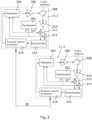
- FIG. 3shows a more detailed block diagram of how a possible reader unit 11.1 implementation to be used in each of the above discussed embodiments may look like. Note that this diagram is only shown here to clearly illustrate the invention and that possible embodiments are not limited to the represented implementation. Two readers are shown, reader 11.1 and reader 11.2, which are connected via a connection 33 (this may be any of the connections 45-47, 56-58, 65-67, 73, 85-87, 95-97 discussed above).
- the reader unit 11.ifurther comprises a protocol control processor 318. This processor 318 controls whether the reader unit 11.i acts as a master or a slave.
- the reader unit 11.itransmits and/or receives modulated carrier waves. It may generate the interrogation data if the reader unit acts as a master. In that case it may interpret the tag reply data obtained by its demodulator or received via the connection 33 from another reader unit which acts as a slave. It may decide which commands to send next if its reader unit acts as a master. In that case this command is provided as a newly generated interrogation signal which is used to modulate the carrier wave generated by its associated master. This interrogation data is also submitted to other reader unit(s) 11.2 via the connection 33.
- the processor 318 of this readerestablishes that the interrogation data which is received from the reader unit which acts as a master is modulated on the carrier wave generated by the synthesizer 302 of the reader unit 11.2. Also the demodulator 316 of the reader unit 11.2 provides the received reply signal to the processor 318 of the reader unit 11.2 and this processor submits this reply signal to the processor 318 of the reader unit 11.1 for further processing as discussed above, such as transmission of the reply signal to the central computer and/or generating a new interrogations signal (which may comprise a command for the tag 13).
- the systemis arranged such that a receiver of the at least one second reader unit 11.2, 11.4 demodulates a received first reply signal of a tag to obtain a first reply wherein the at least one second reader unit sends the first reply to the first reader unit 11.1.
- the first reader unit 11.1determines based on the first reply possible new interrogation data to be transmitted next by means of the first reader unit 11.1 or the at least one second reader unit 11.3, 11.4 or by the first reader unit 11.1 and the at least one second reader unit 11.3, 11.4 in a synchronized manner.
- the system of figure 8may be arranged such that the tag generates a second reply signal which may be received and processed by the reader units as discussed for the first reply signal.
- the systemmay be arranged such that a receiver of the at least one second reader unit 11.2, 11.4 receives a first reply signal of a tag wherein the at least one second reader unit 11.2, 11.4 sends the received first reply signal to the first reader unit 11.1.
- the first reader unit 11.1demodulates the first reply signal obtained from the at least one second reader unit 11.2, 11.4 to obtain a first reply wherein optionally a receiver of the first reader unit 11.1 receives the first reply signal of the tag wherein the first reader unit 11.1 demodulates the first reply signal received by the first reader unit 11.1 to obtain a first reply.
- the systemis arranged to compare all the first replies to obtain a single first reply wherein optionally the comparison of the first replies to obtain the single first reply is carried out in a known manner. For example if two first replies are the same and differ from another first reply the first replies which are the same are accepted as the true first reply and this true first reply is the single first reply obtained. Thus for example based on all the obtained first replies statistically the true first reply may be obtained based on statistical analyses.
- the systemmay be arranged such that receivers of a plurality of second reader units 11.2, 11.4 each receive a first reply signal of a tag wherein each of the second reader units 11.2, 11.4 demodulates the received first reply signals to obtain first replies respectively and wherein each of the second reader units 11.2,11.4 submits its generated first reply to the first reader unit 11.1
- a receiver of the first reader unit 11,1also receives the first reply signal of the tag wherein the first reader unit 11.1 demodulates the first reply signal received by the first reader unit 11.1 to obtain a first reply.
- the systemmore particularly the first reader unit 11.1, is arranged to compare all the first replies to obtain a single first reply wherein optionally the comparison of the first replies to obtain the single first reply is carried out in a known manner, for example as discussed above.
- the systemmay be arranged such that receivers of a plurality of second reader units 11.2, 11.4 each receive a first reply signal of a tag wherein each of these second reader units 11.2, 11.4 sends the received first reply signal to the first reader unit.
- the first reader unit 11.1demodulates the first reply signals obtained from the second reader units to obtain a plurality of first replies.
- a receiver of the first reader unit 11.1also receives the first reply signal of the tag wherein the first reader unit demodulates the first reply signal received by the first reader unit 11.1 to obtain a first reply.
- the systemmore particularly the first reader unit 11.1, is arranged to compare the first replies to obtain a single first reply wherein optionally the comparison of the first replies to obtain the single first reply is carried out in a known manner, for example as discussed above.
- the carrier waveshave frequencies which lay in the UHF band.
- the carrier waveshave different frequencies.
- the carrier wavesmay however also be in mutually different frequency bands.
Landscapes
- Engineering & Computer Science (AREA)
- Physics & Mathematics (AREA)
- Health & Medical Sciences (AREA)
- Toxicology (AREA)
- General Health & Medical Sciences (AREA)
- Electromagnetism (AREA)
- Artificial Intelligence (AREA)
- Computer Vision & Pattern Recognition (AREA)
- General Physics & Mathematics (AREA)
- Theoretical Computer Science (AREA)
- Computer Networks & Wireless Communication (AREA)
- Computer Security & Cryptography (AREA)
- Near-Field Transmission Systems (AREA)
Description
- This invention relates to a preferably Ultra High Frequency (UHF) radio frequency identification (RFID) system comprising multiple RFID reader units, in which the units can generate carrier waves which are modulated by interrogation data to be received by tags. More particularly the invention relates to a system of RFID reader units, comprising a plurality of reader units at least comprising a first reader unit provided with a transmitter for transmitting an electromagnetic interrogation signal comprising a carrier wave which is modulated with interrogation data for interrogating an RFID tag and at least one second reader unit provided with a transmitter for transmitting an electromagnetic interrogation signal comprising a carrier wave which is modulated with interrogation data for interrogating an RFID tag wherein the system is arranged to receive a reply signal generated by an RFID tag in response to a carrier wave modulated with an interrogation signal received by the tag.
- Over the past years, the application of radio frequency signals for identification purposes was shown to have a large benefit for logistical purposes. Radio Frequency Identification (RFID) can be applied to identify, locate and track objects. Of particular interest is Ultra High Frequency (UHF) RFID, since it allows large reading distances and high data rates. This invention is in the field of RFID, more particularly UHF RFID.
- A conventional RFID reading system comprises an RFID interrogator (reader unit) and one or more transponders, commonly referred to as labels or tags. In many implementations the transponders are passive, meaning that they extract their operating power from the RF field supplied by the reader unit, and the communication from the transponder back to the reader unit is based on modulated backscattering of the transmitted signal. This invention relates to powering and interrogating passive (UHF) RFID tags.
- A consequence of passive (UHF) RFID is a limited detection range. For logistical purposes it is crucial that all articles distributed over a large area can be identified and located. In addition, often the articles are packed closely together and environments are commonly challenging for RF signals. To achieve full area coverage and a high reading accuracy in such environments, in general, an RFID system will comprise multiple reader units in close proximity. However, whereas a tag can be collectively powered by the RF fields transmitted by multiple independent reader units, generally it will have difficulty to interpret the mix of interrogation data generated by each independent reader unit. The latter will decrease the likelihood of a successful tag interrogation and diminish the added value of applying multiple RFID reader units. The invention described here relates to techniques to generate optimal benefit of the operation of multiple RFID reader units simultaneously.
- To date, several approaches to solve this problem have been pursued. According to
US 2014/0292494 A1 tags are interrogated using a distributed exciter network. This system comprises a high performance receiver unit and multiple simple exciter units. The receiver unit transmits control signals to the exciter units and determines the operation specifics of the exciters. Using multiple exciters ensures that sufficient forward power can be supplied to the tags, and the high sensitivity of the receiver ensures that even replies of tags that are situated far away can still be received. - Another approach is given in
US 009384376 B2 - Yet another approach is shown in
US 2016/0126753 A1 . This invention also makes use of the benefits obtained from coherent transmission of the signal from multiple readers. However, in this case it is achieved by frequency locking the oscillators of multiple reader units, allowing the reader units to coherently transmit their signals to the tags.US 2016/9373012 B2 discloses a system communicating from a controller, a target location to a first synthesized-beam RFID reader and to a second synthesized-beam RFID reader. Responsive to the communicated target location, a first beam is steered from the first synthesized-beam reader to the target location and a second beam is steered from the second synthesized-beam reader to the target location. The first synthesized-beam reader transmits a modulated RF inventory signal and the second synthesized-beam reader transmits simultaneously a substantially unmodulated RF signal. A tag reply signal is received at one of the first and second synthesized-beam readers. A disadvantage of this system relates to modulation depth issues compromising the read rate - All of the solutions mentioned above, help in supplying sufficient power to the tags and interrogating tags in a challenging environment. However, all of them have several disadvantages which make them less ideal in certain use cases. In the case of
US 2014/0292494 A1 , the fact that the receiver and exciters are physically different units makes the solution less scalable. Additionally, a very sensitive receiver is also very receptive to external disturbance. Solutions proposed inUS 009384376 B2 US 2016/0126753 A1 both apply the principle of coherent addition of electromagnetic fields to obtain optimal benefit of the usage of multiple
transmitters. InUS 009384376 B2 US 2016/0126753 A1 it is proposed to circumvent these difficulties by creating a solution in which the transmitters are synchronized wirelessly. However, this solution requires complex and expensive hardware. Additionally, to achieve full field coverage with coherent transmitters, dedicated phase shifters are needed to move the interference hotspots and zeroes through the area, adding to the complexity of the hardware and the time needed for a full inventory. Furthermore, it is unclear whether coherently transmitting readers will pass the regulatory requirements. - The object of this invention is to provide a system which can be applied to allow multiple (UHF) RFID readers to collaborate, thereby efficiently enhancing the coverage area and read performance of the RFID system. The system according to the invention is defined in
claim 1. The system ofclaim 1 is amongst others characterized in that, the system is arranged such that the first reader unit and the at least one second reader unit, in use, each generate their own carrier wave independently from each other, wherein the carrier waves are each modulated with the same interrogation data in a mutually synchronized way. - The fact that the carrier waves are generated independently from each other for example means that the frequencies of the carrier waves are not locked with respect to each other. Thus their frequencies may vary independently from each other. Thus the frequencies of the independently generated carrier waves will generally be different from each other. In particular the carrier waves generated by the reader units are mutually non-synchronized and/or asynchronous. In particular, the carrier waves generated by the reader units have different frequencies. In particular, the units can independently generate their own carrier waves having
frequencies which are not controlled to be the same and which are modulated by synchronized and identical interrogation data to be received by tags. - According to the first option specified in
claim 1, the system is provided with a control unit which generates the interrogation data, wherein the control unit is communicatively connected with the first reader unit and the at least one second reader unit for submitting the interrogation data to these reader units. The control unit may be one of the reader units or a unit which is exclusively designed for generating interrogation data. - According to the second option specified in
claim 1, the first reader unit is configured to act as a master and the at least one second RFID reader unit is configured to act as a slave, wherein the first reader unit is arranged to generate interrogation data wherein the system is arranged for distributing the interrogation data generated by the first reader unit to the at least one second reader unit, wherein each of the first reader units and the at least one second reader units, in use, generates its own carrier wave, wherein the first reader unit is arranged to modulate the carrier wave generated by the first reader unit with the interrogation data generated by the first reader unit and wherein the at least one second reader unit is arranged to modulate the carrier wave generated by the at least one second reader unit with the interrogation data provided by the first reader unit, such that the first reader unit and the at least one second reader unit each transmit identical and synchronized interrogation data.
The architecture of such a system is the following: each reader unit generates its own carrier wave, with a frequency that might be but need not be equal to frequencies of the carrier waves generated by other reader units. In general the frequencies of the carrier waves generated by the reader units differ from each other. Thus the frequencies of the carrier waves are non correlated and/or independently generated by each reader unit. The interrogation data is distributed throughout a network formed by
the reader units and each reader unit modulates the acquired data onto their own carrier wave. Preferably the role of each reader unit in the network can be configured as master or slave. It is however also possible that a reader unit is fixedly configured as a master unit or slave unit. Also preferably, in addition or alternatively, the operation mode of each reader unit can be set to transmitter, receiver or transceiver. - During an interrogation period, the readers that are configured as master reader units, generate and distribute the interrogation data to the slave units. The reader units that are operating as receivers or as transceivers demodulate the tag reply and may send the acquired data back to the master units or its associated master unit, such that the master unit(s) can determine the next commands to be transmitted. Such command is then part of new to be transmitted interrogation data.
- The reader units may be given roles and operation modes at any time. The proposed setup yields a system with the capability to cooperatively power RFID tags without interfering with the communication protocol or compromising the required modulation depth.
- This invention is substantially different from the approaches mentioned above. Firstly, distributing the relatively slow interrogation data requires less complicated and expensive hardware and cabling than the distribution of a UHF radio frequency signal. In addition, implementation of this invention requires only small changes to commonly used RFID readers. Secondly, using unsynchronized carrier waves, rather than coherent carrier waves, gives a full coverage of the electromagnetic field in a given area, instead of a checkerboard pattern resulting from coherent addition. Thirdly, since the reader units can preferably be configured as master or slave, installation can be easily planned and managed. Fourthly, since the reader units can preferably be configured as transmitter, receiver or transceiver, installation can be easily planned and managed.
- A reader unit according to the invention is characterized in that the reader unit is so arranged that it can act as a master or a slave, wherein if the reader unit acts as a master the processor, in use, generates interrogation data which may be modulated on a carrier wave generated by means of the transmitter wherein the modulated carrier wave is transmitted by means of the transmitter and/or wherein if the reader unit acts as a master the processor provides the generated interrogation data to an output port of the reader unit for submitting the generated interrogation data to another reader unit and wherein if the reader unit acts as a slave the processor, in use, can receive interrogation data from a second outside source not being part of the reader unit for modulating a carrier wave generated by the transmitter and for transmitting the modulated carrier wave by the transmitter and wherein the reader unit is arranged to selectively activate or deactivate the transmitter and wherein the reader unit is arranged to selectively activate or deactivate the receiver. Interrogation data which are synchronized means for example that there is a maximum delay between the interrogation data of half the pulse width of the modulation. Thus synchronization according to the invention implies that the timing difference is small enough such that the tag does not experience the difference or sees it as a problem. More particularly the phase difference is (substantially) zero. Carrier waves which have different frequencies are for example frequencies F1, F2, which differ such that F1 < F2. Preferably it further holds that F2 is smaller than F1+1/Tint, where Tint is the time it takes to successfully interrogate a tag, in case two transmitters are operating in the same frequency channel specified by regulatory agencies (e.g. FCC part 15.247 /ETSI EN 302208). This improves the ability to read a tag. In particular it also holds that carrier waves may have different frequencies such that they lay in different frequency channels as specified by regulatory agencies (e.g. FCC part 15.247 /ETSI EN 302208). Thus, in use, carrier waves which have different frequencies are for example carrier waves with frequencies F1, F2, which differ such that 0<|F2-F1|<1/Tint where Tint is the time it takes to successfully interrogate a tag, in case two transmitters are operating in the same frequency channel specified by regulatory agencies (e.g. FCC part 15.247 /ETSI EN 302208), and/or are for example carrier waves with frequencies F1 and F2 such that they are part of different frequency channels as specified by said regulatory bodies.
Figure 1 is a schematic picture showing in a system according to the invention the read range of two individual RFID readers in white and, in grey, the read range that applies when the readers can collectively interrogate the tag.Figure 2 is a schematic illustration of the RFID reader including a block depicting the modulation interface allowing to distribute the interrogation data to other units in a system according to the invention.Figure 3 shows a block diagram of a possible implementation of two RFID readers that are capable of distributing the modulation data in a system according to the invention.Figure 4 is a schematic view of a system according to the invention in which the interrogation data is distributed through a chain of readers.Figure 5 is a schematic view of a system according to the invention in which the readers form a star network and the interrogation data is distributed with the aid of a communication interface connecting the cables from all readers, e.g. a switch.Figure 6 is a schematic view of a system according to the invention in which the interrogation data is distributed wirelessly to the readers.Figure 7 is a schematic picture showing an example of a transmission setup in which one reader is configured as transmitter and the other is configured to be the receiver in a system not according to the invention.Figure 8 illustrates a general system configuration according to the invention which includes a combination of reader units, in which the operating mode of a first reader unit is set to receiver, a second reader unit as receiver, a third reader unit as transmitter and a fourth reader unit as transceiver.Figure 9 illustrates a general system configuration according to the invention which includes a combination of (slave) readers which are controlled by a central control unit.- A schematic illustration of the added value of the invention is given in
Figure 1 . UHF RFID reader unit 11.1 and UHF RFID reader unit 11.2 are shown, whereinwhite circle 14 andcircle 15 depict the read ranges associated with the reader unit 11 and the reader unit 12, respectively.
A passiveUHF RFID tag 13 is situated outside of the read range of both reader units, and thus, will thetag 13 not be read by the reader units. Agrey section 16 illustrates the region where the addition of the powers supplied by reader unit 11.1 and the reader unit 11.2 is sufficient to power thetag 13. However, if both readers are independently trying to interrogate the tag by means of transmitting an interrogation signal, chances of a successful interrogation cycle are slim due to interference of the modulation of the interrogation signals, decrease of the modulation depth and mixing of the communication protocol followed by each reader. The present invention describes a solution for these problems by adding a schematically shown layer ofcommunication 17 between the readers in which the interrogation data is shared and by means of which the interrogation data is synchronized. Even though both readers generate their own carrier waves, which in principle will be unsynchronized, they are able to do a synchronized interrogation of the tag, yielding a high read rate. Each reader transmits an interrogation signal comprising a carrier wave which is modulated with interrogation date. Because the interrogation data modulated on the carrier waves are synchronized, the grey circle provides a range which is larger than the sum of the twowhite circles
that the carrier waves itself are not mutually synchronized (because the carrier waves are generated independently from each other wherein their frequencies are not locked to each other) has no negative impact on the ability of theRFID tag 13 to extract power from the simultaneously transmitted interrogation signals. Thus for providing sufficient power to thetag 13 the carrier waves need not to be synchronized whereas for transmitting the interrogation data to the tag the interrogation data which are modulated on the carrier waves are mutually synchronized. The synchronization of the interrogation data can be realized in several ways as will be discussed hereinafter. Figure 2 shows a schematic illustration of an embodiment of a UHF RFID reader unit 11.i (i=1,2, ---) that satisfies this invention. Multiple of such reader units 11.i are combined into a system according to the invention, an example of which is shown infigures 1 ,4-6 and8, 9 . The core of the reader unit 11.i is represented byblock 21 and includes all the signal generation, amplification and processing that is required to read RFID tags 13. Anantenna 19 applied for transmitting and receiving is connected toconnector 22 and there might be a receiveantenna connector 3 for the purpose of a bi-static configuration.Block 23 depicts the modulation interface, where the interrogation data is generated or wherein external generated interrogation data is inserted. In order to distribute and receive the interrogation data to and from other reader units 11.i in the network, several communication ports are envisioned. Theblock 23 can be provided with aconnector - In this example, four possibilities are shown for setting up a system according to the invention, but the invention is not limited to these four.
- A first possibility is shown in
figure 4 . In case of a wired connection between the reader units in the network,connector 24 andconnector 25 can be configured to be both input and/or output for the modulation, such that each reader operates as a switch to obtain a chain network. For example second reader units 11.2, 11.3, 11.4 each operate in a slave mode. In this mode it holds that if an interrogation signal is supplied toconnector 24 it functions as an input and this interrogation signal also becomes available onconnector 25 which functions as an output. This is shown for reader unit 11.3. For a reader in the slave mode it also holds that if an interrogation signal is supplied toconnector 25 it functions as an input and this interrogation signal also becomes available onconnector 24 which functions as an output. This is shown for reader unit 11.2. It follows that in this embodiment each second reader unit functions as a slave and could also be referred to as a slave reader unit. - Furthermore first reader unit 11.1 functions in a master mode. This means that the reader unit 11.1 generates an interrogation signal wherein this interrogation signal is made available on
connectors - In this example, the first reader unit 11.1 also generates its own carrier wave. This carrier wave is modulated with the interrogation signal which is also generated by the reader unit. The modulated carrier wave is transmitted by means of the
antenna 22 of the first reader unit 11.1. - The interrogation signal generated by the first reader unit 11.1 is also submitted to the second reader unit 11.2 via
wired connection 45. The second reader unit 11.2 also generates its own carrier wave. This carrier wave is modulated with the interrogation signal received via itsconnector 25. This modulated carrier wave is transmitted by means of theantenna 22 of the second reader unit 11.2. It is noted that the carrier waves of the first reader unit and the second reader unit are not synchronized. Both carrier waves do have different frequencies. The interrogation signal used by the first reader unit 11.1 for modulating its carrier wave is however synchronized with the interrogation signal used by the second reader unit 11.2 for modulating its carrier wave. - The interrogation signal generated by the first reader unit 11.1 is also submitted via
wired connection 46 to the second reader unit 11.3. The second reader unit 11.3 also generates its own carrier wave. This carrier wave is modulated with the interrogation signal received via itsconnector 24. This modulated carrier wave is transmitted by means of theantenna 22 of the second reader unit 11.3. It is noted that the carrier waves of the first reader unit and the third reader unit are not synchronized. This means that both carrier waves do have different frequencies. The interrogation signal used by the first reader unit 11.1 for modulating its carrier wave is however synchronized with the interrogation signal used by the second reader unit 11.3 for modulating its carrier wave. - The interrogation signal generated by the first reader unit 11.1 is submitted via
wired connection 46 toconnector 24 of the second reader unit 11.3 and fromconnector 25 of the second reader unit 11.3 toconnector 24 of the second reader unit 11.4. The second reader unit 11.4 also generates its own carrier wave. This carrier wave is modulated with the interrogation signal received via itsconnector 24. This modulated carrier wave is transmitted by means of theantenna 22 of the second reader unit 11.4. It is noted that the carrier waves of the first reader unit 11.1 and the second reader unit 11.4 are not synchronized. Both carrier waves do have however the same (ground) frequency. The interrogation signal used by the first reader unit 11.1 for modulating its carrier wave is however synchronized with the interrogation signal used by the second reader unit 11.4 for modulating its carrier wave. - The carrier waves of the second reader units 11.2-11.4 are also mutually non-synchronized meaning that the carrier waves of all the reader units 11-1-11.4 are non-synchronized. However all these carrier waves are modulated with the same interrogation signal wherein the interrogation signals used by the readers 11.1-11.4 for modulating its respective carrier waves are mutually synchronized.
- A
tag 13 responds if it receives one or more of the carrier waves by modulating such received carrier waves with reply data and by backscattering (also referred to as transmitting) these modulated carrier waves as a reply signal. The reply data may for example comprise an identification code of the tag. Thetag 13 may work according to the known absorption or transmission principle for transmitting the reply signal. In this example the reader unit 11.1 is also configured as a receiver for receiving the reply. In response to the received reply the reader unit 11.1 may send the received reply data for example to acentral computer 100 for further processing. Thecomputer 100 is communicatively connected with the reader units 11.i.Thisconnection 104 may be a wired and/or wireless connection (schematically shown). It is also possible that the reader unit 11.1 generates a new interrogation signal, for example comprising a command for thetag 13. The carrier wave generated by the reader unit 11.1 is modulated with the new interrogation signal. This new interrogation signal is also submitted to the readers 11.2-11.4 as discussed above. Each reader 11.2-11.4 modulates its carrier wave with the new interrogation signal as discussed above for the earlier interrogation signal. The command may for example be to measure a temperature if the tag is provided with a temperature sensor. In response thetag 13 may measure the temperature and generate new reply data to be backscattered. In this example the readers 11.2-11.4 are only configured to act as a transmitter. The term reader is therefor related to a unit which comprises a transmitter and/or receiver. In this example the reader units each comprise a receiver however these receivers are configured to be inactive or not being used. - It is however also possible that the reader units 11.2-11.4 are each provided with a receiver which is activated. If for example reader unit 11.3 would receive a reply signal transmitted by the
tag 13 the reader unit 11.3 will demodulate the reply signal and will send the received reply data to the reader unit 11.1 viawired connection 46. The reader unit 11.1 may send the received reply data for example to thecentral computer 100 for further processing. It is also possible that the reader unit 11.1 generates a new interrogation signal, for example comprising a command for thetag 13. Each reader 11.2-11.4 modulates its carrier wave with the new interrogation signal as discussed above for the earlier interrogation signal. - In this example the reader units 11.1-11.4 are identical and comprise a receiver and a transmitter. Each reader may be configured to function in a master mode or slave mode as discussed above. In the example of
Figure 4 the reader unit 11.1 is configured to act as a master and the reader units 11.2-11.4 are configured to act as a slave. Thus in this example configured means the reader unit may also be reconfigured. According to a special embodiment of the invention this holds both for the options master and slave and for the options transmitter used or not, and receiver used or not. If both transmitter and receiver are used this may also be referred to as a transceiver being used. Thus a reader unit 11.i may be configured to act as a slave or a master and may be configured to receive and/or transmit. For example reader unit may be configured as a master wherein the receiver and the transmitter are not used. In that case the master unit only generates the interrogation data to be transmitted by other reader units. In that case for example reader unit 11.2 may be configured as a slave and a transmitter. Reader unit 11.3 may be configured as a slave and a receiver. Reader unit 11.4 may be configured as a slave and a transceiver. Alternatively reader unit 11.1 may also be configured as a transmitter
and/or receiver. Whatever happens, the system as a whole should comprise at least two reader units having an active transmitter and a reader unit having an active receiver. Therein a reader unit having an active transmitter and a reader unit having an active receiver may be the same. - The (re) configuration can be carried out by an operator, for example by submitting (re)configuration signals to the
connector 24 of the reading unit. - It is however also possible that a reader unit cannot be reconfigured with respect to the master and slave mode. In that case such reader unit is fixedly configured to work as a master or slave. It is however also possible that a reading unit cannot be reconfigured with respect to its receiver being used (active) or not. In that case such reader unit is provided with an active receiver or no receiver.
- Thus in
Figure 4 an example is shown of a system comprising four reader units connected in a chain layout. In the present example the role of reader unit 11.1 is that of a master. The master is set to generate the interrogation data and distribute the data via wired connections (45-47) to the other units, referred to as slaves (reader units 11.2-11.4). Each reader unit will subsequently modulate the data onto its own carrier wave and transmit the signal via itsown antenna 19. In this way all units will transmit synchronized interrogation commands to the tag. In this example the operation mode of the master (reader unit 11.1) is set to be the receiving unit. If the interrogation requires multiple commands, such as obtaining an Electronic Product Code (EPC) of a tag in theEPCglobal Class 1Generation 2 protocol, the master 11.1 will generate new interrogation data according to the received tag reply and again distribute these to each unit in the network. In this particular embodiment the master may be the only unit capable of receiving the tag reply, but the invention is certainly not limited to a single receiving unit; as discussed the reader units 11.2-11.4 may also be provided with a receiver which is active. - A second example is shown in
figure 5 wherein the readers are connected in a star network configuration, either 24 or 25 will be superfluous and one of the two connectors may be omitted (as shown infigure 5 for connector 25) or not being used. In the example offigure 5 anexternal switch 55 can be used to facilitate the connection to all units by means of respective wired connection 56-58. Infigure 5 the reader units 11.1-11.4 operate in the same manner as discussed for the system according tofigure 4 . The difference is that the interrogation data generated by reader unit 11.1 is submitted to each of the reader units 11.2-11.4 via theswitch 55. Also possible reply data received by the reader units 11.2-11.4 is submitted to the reader unit 11.1 via theswitch 55. - Thus
figure 5 depicts another embodiment of a system similar to that shown inFigure 4 . InFigure 5 the units are wired in a star network configuration. In this case, the readers 11.1-11.4 require only a single wired modulation connection and an external switch (55) is used to allow distribution to all units via wired connections 56-59. A practical implementation of this embodiment can be, but is not limited to, the use of Ethernet as a communication interface for the modulation and use of an off-the-shelf Ethernet switch to connect the units. - A third example is shown in
figure 6 wherein a system is shown which comprises a wireless connection for the transmission of interrogation data generated by the first reader unit 11.1 to the reader units 11.2.11.4. A possible reply received by any of the reader units 11.2-11.4 may be transmitted to the reader unit 11.1 via the same wireless connection. To this extent anantenna 27 can be connected toconnector 26. - Thus another embodiment of the present invention is shown in
Figure 6 where a wireless connection is used for the distribution of the interrogation data. As indicated each reader unit is equipped with anadditional antenna 26 for this purpose. Wireless connections 65-67 are formed, over which the modulation data can be distributed, possibly also the
reply data received by any of the reader units 11.2-11.4 to the reader unit 11.1. - Another example is shown in
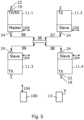
figure 9 . In this example all reader units 11.2-11.3 are configured to act as a slave reader unit. Reader unit 11.2 acts as a transceiver for transmitting the modulated carrier wave and for receiving a reply signal from thetag 13. Reader unit 11.3 acts as a transmitter for transmitting the modulated carrier wave. Reader unit 11.4 acts as a receiver for receiving a reply signal from thetag 13. The reader units 11.2-11.4 are communicatively connected with acentral processor 102 via connection lines 91-93 which may be wired or wireless communication lines. The central processor acts as a master and generates the interrogation data which is submitted to each of the reader units 11.2-11.4. Each of the reader units 11.2-11.3 modulates its own generated carrier wave with the interrogation data for transmission. A reply of a tag which is received by the reader unit 11.2 and/or 11.4 is submitted to thecentral processor 102 for further processing. The central processor may generate in response to the received reply data a command for thetag 13 which is submitted as new interrogation data to the reader units 11.2 and 11.3 for transmission. Also theprocessor 102 may submit the reply data to a central computer 110. - It is noted that optionally the control unit is one of the plurality of reader units provided with a receiver for receiving a reply signal and/or a transmitter for generating its own carrier wave, modulating its own carrier wave with the interrogation data and for transmitting its own modulated carrier wave. Note that in the
examples connections
present example, 23 is illustrated as a separate block that is attached to 21 but in likely embodiments of theinvention 23 will be a part of 21 (seefigure 2 ). Figure 7 schematically illustrates a transmission setup not according to the present invention. Therein reader unit 11.1 is operating as transmitter and reader unit 11.2 is operating as receiver. The interrogation data is shared between units 11.1 and 11.2 with the aid ofconnection 73, allowing bidirectional communication. For the sake of clarity and by way of example, the commands that will be transmitted in a tag interrogation cycle using theEPCglobal Class 1Generation 2 protocol, are added to the figure. However this is merely an example, other protocols are also possible. Reader unit 11.1, which role is master, starts with transmitting a Query command which is received by thetag 13. The tag replies an RN16 via backscatter modulation, which is in turn received by reader unit 11.22. Reader unit 11.2 demodulates the tag reply and communicates the obtained RN16 value to reader unit 11.1. Reader unit 11.1 then acknowledges receiving the RN16 by transmitting this back to thetag 13. Thetag 13 verifies whether or not theRN 16 transmitted by unit 11.1 is correct, and if so, replies by backscattering a Protocol Control word, the EPC and the CRC check. Again, reader unit 11.2 demodulates the tag reply and sends the acquired data to reader unit 11.1 viaconnection 73. Finally, if the CRC checks out, reader unit 11.1 transmits an ACK command and thetag 13 sets its inventoried flag.
As an illustration of the plethora of possibilities of the invention,Figure 8 shows yet another configuration of the system. Again the reader units can preferably be (re)configured to its special role as master or slave and as receiver, transmitter or transmitter + receiver (transceiver). A
system of four RFID reader units is depicted, in which the operating mode of unit reader 11.1 is set to receiver, that of reader unit 11.2 as receiver, that of reader unit 11.3 as transmitter and that of reader unit 11.4 as transceiver. Furthermore, the role of reader unit 11.1 is in this example set to master and the roles of the other reader units 11.2-11.4 are set as slave. Thebi-directional communication lines EPCglobal Class 1Generation 2 protocol.- Finally, the embodiment is not limited to having only a single master unit. In larger installations the system could decide that individual readers are spaced apart far enough for multiple master units to be active at any given time, with each of the master units controlling a subset of the available transceivers. Which masters are active could be different from interrogation to interrogation.
Figure 3 shows a more detailed block diagram of how a possible reader unit 11.1 implementation to be used in each of the above discussed embodiments may look like. Note that this diagram is only shown here to clearly illustrate the invention and that possible embodiments are not limited to the represented implementation. Two readers are shown, reader 11.1 and reader 11.2, which are connected via a connection 33 (this may be any of the connections 45-47, 56-58, 65-67, 73, 85-87, 95-97 discussed above).- The core of the reader unit 11.i (i=1,2) comprises a
synthesizer 302 that generates the radio frequency carrier wave, amodulator 304 which modulates the interrogation data onto the carrier wave, apower amplifier 306 to amplify the signal to the desired output power, acirculator 308 to isolate the transmit and receive section of the reader unit, anamplifier 310 to amplify the received tag reply to a desired power, twomixers demodulator 316 to obtain the data that is backscattered by the tag. The reader unit 11.i further comprises aprotocol control processor 318. Thisprocessor 318 controls whether the reader unit 11.i acts as a master or a slave. It also controls whether the reader unit 11.i, in use, transmits and/or receives modulated carrier waves. It may generate the interrogation data if the reader unit acts as a master. In that case it may interpret the tag reply data obtained by its demodulator or received via theconnection 33 from another reader unit which acts as a slave. It may decide which commands to send next if its reader unit acts as a master. In that case this command is provided as a newly generated interrogation signal which is used to modulate the carrier wave generated by its associated master. This interrogation data is also submitted to other reader unit(s) 11.2 via theconnection 33. If the reader functions as a slave (such as reader unit 11.2) theprocessor 318 of this reader establishes that the interrogation data which is received from the reader unit which acts as a master is modulated on the carrier wave generated by thesynthesizer 302 of the reader unit 11.2. Also thedemodulator 316 of the reader unit 11.2 provides the received reply signal to theprocessor 318 of the reader unit 11.2 and this processor submits this reply signal to theprocessor 318 of the reader unit 11.1 for further processing as discussed above, such as transmission of the reply signal to the central computer and/or generating a new interrogations signal (which may comprise a command for the tag 13). - In the above embodiments, for example with respect to
figure 8 , the system is arranged such that a receiver of the at least one second reader unit 11.2, 11.4 demodulates a received first reply signal of a tag to obtain a first reply wherein the at least one second reader unit sends the first reply to the first reader unit 11.1. The first reader unit 11.1 determines based on the first reply possible new interrogation data to be transmitted next by means of the first reader unit 11.1 or the at least one second reader unit 11.3, 11.4 or by the first reader unit 11.1 and the at least one second reader unit 11.3, 11.4 in a synchronized manner. Optionally the system offigure 8 may be arranged such that the tag generates a second reply signal which may be received and processed by the reader units as discussed for the first reply signal. - Additionally or alternatively in the above embodiments, for example with respect to
figure 8 , the system may be arranged such that a receiver of the at least one second reader unit 11.2, 11.4 receives a first reply signal of a tag wherein the at least one second reader unit 11.2, 11.4 sends the received first reply signal to the first reader unit 11.1. The first reader unit 11.1 demodulates the first reply signal obtained from the at least one second reader unit 11.2, 11.4 to obtain a first reply wherein optionally a receiver of the first reader unit 11.1 receives the first reply signal of the tag wherein the first reader unit 11.1 demodulates the first reply signal received by the first reader unit 11.1 to obtain a first reply. Optionally the system, more particularly the first reader unit 11.1, is arranged to compare all the first replies to obtain a single first reply wherein optionally the comparison of the first replies to obtain the single first reply is carried out in a known manner. For example if two first replies are the same and differ from another first reply the first replies which are the same are accepted as the true first reply and this true first reply is the single first reply obtained. Thus for example based on all the obtained first replies statistically the true first reply may be obtained based on statistical analyses. - Additionally or alternatively in the above embodiments, for example with respect to
figure 8 , the system may be arranged such that receivers of a plurality of second reader units 11.2, 11.4 each receive a first reply signal of a tag wherein each of the second reader units 11.2, 11.4 demodulates the received first reply signals to obtain first replies respectively and wherein each of the second reader units 11.2,11.4 submits its generated first reply to the first reader unit 11.1 Optionally a receiver of thefirst reader unit 11,1 also receives the first reply signal of the tag wherein the first reader unit 11.1 demodulates the first reply signal received by the first reader unit 11.1 to obtain a first reply. Optionally the system, more particularly the first reader unit 11.1, is arranged to compare all the first replies to obtain a single first reply wherein optionally the comparison of the first replies to obtain the single first reply is carried out in a known manner, for example as discussed above. - Additionally or alternatively in the above embodiments, for example with respect to
figure 8 , the system may be arranged such that receivers of a plurality of second reader units 11.2, 11.4 each receive a first reply signal of a tag wherein each of these second reader units 11.2, 11.4 sends the received first reply signal to the first reader unit. The first reader unit 11.1 demodulates the first reply signals obtained from the second reader units to obtain a plurality of first replies. Optionally a receiver of the first reader unit 11.1 also receives the first reply signal of the tag wherein the first reader unit demodulates the first reply signal received by the first reader unit 11.1 to obtain a first reply. Optionally the system, more particularly the first reader unit 11.1, is arranged to compare the first replies to obtain a single first reply wherein optionally the comparison of the first replies to obtain the single first reply is carried out in a known manner, for example as discussed above. - In the above examples the carrier waves have frequencies which lay in the UHF band. The carrier waves have different frequencies. The carrier waves may however also be in mutually different frequency bands.
Claims (22)
- A system of RFID reader units, comprising a plurality of reader units (11.1, 11.2, 11.3, 11.4, 11.i) at least comprising a first reader unit (11.1) and at least one second reader unit, the system being arranged such that the first reader unit (11.1) and the at least one second reader unit (11.2, 11.3, 11.4), in use, each generate their own carrier wave independently from each other,the first reader unit (11.1) is arranged to modulate the carrier wave generated by the first reader unit with interrogation data to generate and is provided with a transmitter for transmitting an electromagnetic interrogation signal comprising the carrier wave modulated by the first reader unit for interrogating an RFID tag; andthe at least one second reader unit (11.2, 11.3, 11.4) is arranged to modulate the carrier wave generated by the second reader unit with interrogation data and is provided with a transmitter for transmitting an electromagnetic interrogation signal comprising a carrier wave modulated by the at least one second reader unit for interrogating an RFID tag,wherein the system is arranged to receive a reply signal generated by an RFID tag (13) in response to a carrier wave modulated with the interrogation signal received by the tag,characterized in that the system is arranged such that with the first reader unit (11.1) and the at least one second reader unit (11.2, 11.3, 11.4), in use, the first reader unit and the at least one second reader unit each transmit identical and synchronized interrogation data, wherein either according to a first option the system is provided with a control unit (104) which generates the interrogation data, wherein the control unit is communicatively connected (91, 92, 93) with the first reader unit (11.2) and the at least one second reader unit (11.3, 11.4) for submitting the interrogation data to these reader units or according to a second option the first reader unit (11.1) is configured to act as a master, wherein the first reader unit is arranged to generate the interrogation data and the at least one second RFID reader unit (11.2, 11.3, 11.4) is configured to act as a slave, and the system is arranged for distributing the interrogation data generated by the first reader unit to the at least one second reader unit.
- The system according to claim 1,characterized in that the carrier waves generated by the first reader unit (11.1) and the at least one second reader unit (11.2, 11.3, 11.4) are mutually non-synchronized and/or asynchronous and/or non correlated and/or independently generated by each reader unit.
- The system according to claim 1 or 2,characterized in that the carrier waves generated by the first reader unit (11.1) and the at least one second reader unit (11.2, 11.3, 11.4) respectively have different frequencies.
- The system according to any preceding claim,characterized in that in the first option the control unit is one of the plurality of reader units provided with a receiver for receiving a reply signal and/or a transmitter for generating its own carrier wave, modulating its own carrier wave with the interrogation data and for transmitting its own modulated carrier wave.
- The system according to claim 4,characterized in that the system is provided with a wired and/or wireless connection (33, 45, 46, 47) between the first reader unit (11.1), the at least one second reader unit (11.2) and the control unit for distributing the interrogation data over these reader units.
- The system according to any preceding claim,characterized in that the first reader unit is provided with a receiver for receiving the reply signal and/or the at least one second reader unit is provided with a receiver for receiving the reply signal.
- The system according to any preceding claim,characterized in that, at least one of the reader units comprises a receiver for receiving a signal generated by a tag (13) in response to an interrogation signal received by the tag, wherein:the system is arranged such that a receiver of the at least one second reader unit (FIG. 7, 11.2) demodulates a received first reply signal of a tag to obtain a first reply wherein the at least one second reader unit sends the first reply to the first reader unit (11.1), wherein the first reader unit based on the first reply determines possible new interrogation data to be transmitted next by means of the first reader unit or the at least one second reader unit or by the first reader unit and the at least one second reader unit in a synchronized manner; and/orthe system is arranged such that a receiver of the at least one second reader unit receives a first reply signal of a tag wherein the at least one second reader unit sends the received first reply signal to the first reader unit, wherein the first reader unit demodulates the first reply signal obtained from the at least one second reader unit to obtain a first reply wherein optionally a receiver of the first reader unit receives the first reply signal of the tag wherein the first reader unit demodulates the first reply signal received by the first reader unit to obtain a first reply wherein optionally the system, more particularly the first reader unit, is arranged to compare all the first replies to obtain a single first reply wherein optionally the comparison of the first replies to obtain the single first reply is carried out in a known manner; and/orthe system is arranged such that receivers of a plurality of second reader units (FIG. 8, 11.2, 11.3, 11.4) each receive a first reply signal of a tag wherein each of the second reader units demodulates the received first reply signals to obtain first replies respectively and wherein each of the second reader units submits its generated first reply to the first reader unit (11.1), wherein optionally a receiver of the first reader unit receives the first reply signal of the tag wherein the first reader unit demodulates the first reply signal received by the first reader unit to obtain a first reply and wherein optionally the system, more particularly the first reader unit, is arranged to compare all the first replies to obtain a single first reply wherein optionally the comparison of the first replies to obtain the single first reply is carried out in a known manner; and/orthe system is arranged such that receivers of a plurality of second reader units each receive a first reply signal of a tag wherein each of the second reader units sends the received first reply signal to the first reader unit, wherein the first reader unit demodulates the first reply signals obtained from the second reader units to obtain a plurality of first replies wherein optionally a receiver of the first reader unit receives the first reply signal of the tag wherein the first reader unit demodulates the first reply signal received by the first reader unit to obtain a first reply and wherein optionally the system, more particularly the first reader unit is arranged to compare the first replies to obtain a single first reply wherein optionally the comparison of the first replies to obtain the single first reply is carried out in a known manner.
- The system according to any preceding claim,characterized in that the system is provided with a plurality of second reader units (11.2, 11.3, 11.4).
- The system according to any preceding claim,characterized in that the system comprises at least one reader unit (FIG. 8, 11.1, 11.2, 11.3, 11.4) which is arranged to selectively act as a master or slave.
- The system according to any preceding claim,characterized in that the system according to the second option is provided with a wired (FIG. 4, 45, 46) and/or wireless (FIG. 6, 65-67) connection between the first reader unit (11.1) and the at least one second reader unit (11.2, 11.3, 11.4) for distributing the interrogation data to the at least one second reader unit.
- The system according to any preceding claim,characterized in that the system according to the second option is provided with a plurality of first reader units which each, in use, act as a master unit at any given time, wherein the system is arranged such that each first reader unit controls an associated subset of the total available second reader units.
- The system according to claim 11, wherein at least one of the reader units is arranged to be re-configured, possibly after any number of interrogation cycles.
- The system according to any preceding claim, wherein the system according to the second option is arranged such that at least one of the first reader units can be re-configured (after any number of interrogation cycles) into a second reader unit which operates as a slave.
- The system according to any preceding claim,characterized in that the system according to the second option is arranged such that at least one of the second reader units can be re-configured (after any number of interrogation cycles) into a first reader unit which operates as a master.
- The system according to any preceding claim,characterized in that at least one of the reader units in the system according to the second option is arranged to be selectively configured into a first reader unit so that it operates as a master or a second reader unit so that it operates as a slave.
- A system according to any preceding claim,characterized in that at least one of the reader units is arranged to selectively operate as a transmitter only, a receiver only, or both as a transmitter and receiver in combination.
- The system according to any preceding claim,characterized in that the collection of frequencies of the carrier waves generated by the reader units are all the same or comprise different frequencies.
- The system according to any preceding claim, wherein at least one of the reader units, a plurality of the reader units or each reader unit is provided with a beamforming antenna.
- The system according to claim 18,characterized in that a reader unit which is provided with a beam forming antenna is arranged to switch between multiple beams wherein a beam is a receiver beam and/or a transmitter beam.
- The system according to any preceding claim, wherein at least one of the reader units, a plurality of the reader units or each reader unit is with provided multiple antennas and a multiplexer wherein the transmitter and/or receiver of a reader unit is connected to the multiple antennas via the multiplexer to switch between multiple beams wherein a beam is a receiver beam and/or a transmitter beam.
- The system according to any preceding claim,characterized in that at least one of the reader units, a plurality of the reader units or each reader unit is a UHF RFID reader unit.
- A reader unit (FIG. 3, 11.1) comprising a transmitter (302, 304, 306, 308,TX/RX antenna), receiver (TX/RX antenna, 308, 310, 312, 314, 316) and a processor (318) ,characterized in that the reader unit is so arranged that it can act as a master or a slave,wherein if the reader unit (11.1) acts as a master the processor (318), in use, generates interrogation data which may be modulated on a carrier wave generated by means of the transmitter wherein the modulated carrier wave is transmitted by means of the transmitter and/or wherein if the reader unit acts as a master the processor provides the generated interrogation data to an output port of the reader unit for submitting the generated interrogation data to another reader unit (11.2) andwherein if the reader unit acts as a slave- the processor (318), in use, can receive interrogation data from a second outside source (11.1) not being part of the reader unit (11.2) for modulating a carrier wave generated by the transmitter and for transmitting the modulated carrier wave by the transmitter and- wherein the reader unit is arranged to selectively activate or deactivate the transmitter and- wherein the reader unit is arranged to selectively activate or deactivate the receiver.
Applications Claiming Priority (1)
| Application Number | Priority Date | Filing Date | Title |
|---|---|---|---|
| NL2019672ANL2019672B1 (en) | 2017-10-05 | 2017-10-05 | System of RFID reader units transmitting synchronized modulation using asynchronous carrier waves |
Publications (2)
| Publication Number | Publication Date |
|---|---|
| EP3467699A1 EP3467699A1 (en) | 2019-04-10 |
| EP3467699B1true EP3467699B1 (en) | 2023-08-30 |
Family
ID=60451144
Family Applications (1)
| Application Number | Title | Priority Date | Filing Date |
|---|---|---|---|
| EP18198548.2AActiveEP3467699B1 (en) | 2017-10-05 | 2018-10-04 | System of rfid reader units transmitting synchronized modulation using asynchronous carrier waves |
Country Status (4)
| Country | Link |
|---|---|
| US (1) | US11087102B2 (en) |
| EP (1) | EP3467699B1 (en) |
| ES (1) | ES2959661T3 (en) |
| NL (1) | NL2019672B1 (en) |
Families Citing this family (296)
| Publication number | Priority date | Publication date | Assignee | Title |
|---|---|---|---|---|
| US20070084897A1 (en) | 2003-05-20 | 2007-04-19 | Shelton Frederick E Iv | Articulating surgical stapling instrument incorporating a two-piece e-beam firing mechanism |
| US9060770B2 (en) | 2003-05-20 | 2015-06-23 | Ethicon Endo-Surgery, Inc. | Robotically-driven surgical instrument with E-beam driver |
| US9072535B2 (en) | 2011-05-27 | 2015-07-07 | Ethicon Endo-Surgery, Inc. | Surgical stapling instruments with rotatable staple deployment arrangements |
| US11890012B2 (en) | 2004-07-28 | 2024-02-06 | Cilag Gmbh International | Staple cartridge comprising cartridge body and attached support |
| US7934630B2 (en) | 2005-08-31 | 2011-05-03 | Ethicon Endo-Surgery, Inc. | Staple cartridges for forming staples having differing formed staple heights |
| US7669746B2 (en) | 2005-08-31 | 2010-03-02 | Ethicon Endo-Surgery, Inc. | Staple cartridges for forming staples having differing formed staple heights |
| US11246590B2 (en) | 2005-08-31 | 2022-02-15 | Cilag Gmbh International | Staple cartridge including staple drivers having different unfired heights |
| US10159482B2 (en) | 2005-08-31 | 2018-12-25 | Ethicon Llc | Fastener cartridge assembly comprising a fixed anvil and different staple heights |
| US11484312B2 (en) | 2005-08-31 | 2022-11-01 | Cilag Gmbh International | Staple cartridge comprising a staple driver arrangement |
| US20070106317A1 (en) | 2005-11-09 | 2007-05-10 | Shelton Frederick E Iv | Hydraulically and electrically actuated articulation joints for surgical instruments |
| US8708213B2 (en) | 2006-01-31 | 2014-04-29 | Ethicon Endo-Surgery, Inc. | Surgical instrument having a feedback system |
| US11793518B2 (en) | 2006-01-31 | 2023-10-24 | Cilag Gmbh International | Powered surgical instruments with firing system lockout arrangements |
| US11278279B2 (en) | 2006-01-31 | 2022-03-22 | Cilag Gmbh International | Surgical instrument assembly |
| US8820603B2 (en) | 2006-01-31 | 2014-09-02 | Ethicon Endo-Surgery, Inc. | Accessing data stored in a memory of a surgical instrument |
| US7845537B2 (en) | 2006-01-31 | 2010-12-07 | Ethicon Endo-Surgery, Inc. | Surgical instrument having recording capabilities |
| US20110295295A1 (en) | 2006-01-31 | 2011-12-01 | Ethicon Endo-Surgery, Inc. | Robotically-controlled surgical instrument having recording capabilities |
| US7753904B2 (en) | 2006-01-31 | 2010-07-13 | Ethicon Endo-Surgery, Inc. | Endoscopic surgical instrument with a handle that can articulate with respect to the shaft |
| US8186555B2 (en) | 2006-01-31 | 2012-05-29 | Ethicon Endo-Surgery, Inc. | Motor-driven surgical cutting and fastening instrument with mechanical closure system |
| US20120292367A1 (en) | 2006-01-31 | 2012-11-22 | Ethicon Endo-Surgery, Inc. | Robotically-controlled end effector |
| US8992422B2 (en) | 2006-03-23 | 2015-03-31 | Ethicon Endo-Surgery, Inc. | Robotically-controlled endoscopic accessory channel |
| US8322455B2 (en) | 2006-06-27 | 2012-12-04 | Ethicon Endo-Surgery, Inc. | Manually driven surgical cutting and fastening instrument |
| US10568652B2 (en) | 2006-09-29 | 2020-02-25 | Ethicon Llc | Surgical staples having attached drivers of different heights and stapling instruments for deploying the same |
| US11980366B2 (en) | 2006-10-03 | 2024-05-14 | Cilag Gmbh International | Surgical instrument |
| US8684253B2 (en) | 2007-01-10 | 2014-04-01 | Ethicon Endo-Surgery, Inc. | Surgical instrument with wireless communication between a control unit of a robotic system and remote sensor |
| US11291441B2 (en) | 2007-01-10 | 2022-04-05 | Cilag Gmbh International | Surgical instrument with wireless communication between control unit and remote sensor |
| US8632535B2 (en) | 2007-01-10 | 2014-01-21 | Ethicon Endo-Surgery, Inc. | Interlock and surgical instrument including same |
| US20080169333A1 (en) | 2007-01-11 | 2008-07-17 | Shelton Frederick E | Surgical stapler end effector with tapered distal end |
| US7673782B2 (en) | 2007-03-15 | 2010-03-09 | Ethicon Endo-Surgery, Inc. | Surgical stapling instrument having a releasable buttress material |
| US11564682B2 (en) | 2007-06-04 | 2023-01-31 | Cilag Gmbh International | Surgical stapler device |
| US8931682B2 (en) | 2007-06-04 | 2015-01-13 | Ethicon Endo-Surgery, Inc. | Robotically-controlled shaft based rotary drive systems for surgical instruments |
| US7753245B2 (en) | 2007-06-22 | 2010-07-13 | Ethicon Endo-Surgery, Inc. | Surgical stapling instruments |
| US11849941B2 (en) | 2007-06-29 | 2023-12-26 | Cilag Gmbh International | Staple cartridge having staple cavities extending at a transverse angle relative to a longitudinal cartridge axis |
| US11986183B2 (en) | 2008-02-14 | 2024-05-21 | Cilag Gmbh International | Surgical cutting and fastening instrument comprising a plurality of sensors to measure an electrical parameter |
| US9179912B2 (en) | 2008-02-14 | 2015-11-10 | Ethicon Endo-Surgery, Inc. | Robotically-controlled motorized surgical cutting and fastening instrument |
| US7819298B2 (en) | 2008-02-14 | 2010-10-26 | Ethicon Endo-Surgery, Inc. | Surgical stapling apparatus with control features operable with one hand |
| JP5410110B2 (en) | 2008-02-14 | 2014-02-05 | エシコン・エンド−サージェリィ・インコーポレイテッド | Surgical cutting / fixing instrument with RF electrode |
| US8573465B2 (en) | 2008-02-14 | 2013-11-05 | Ethicon Endo-Surgery, Inc. | Robotically-controlled surgical end effector system with rotary actuated closure systems |
| US8636736B2 (en) | 2008-02-14 | 2014-01-28 | Ethicon Endo-Surgery, Inc. | Motorized surgical cutting and fastening instrument |
| US7866527B2 (en) | 2008-02-14 | 2011-01-11 | Ethicon Endo-Surgery, Inc. | Surgical stapling apparatus with interlockable firing system |
| US9585657B2 (en) | 2008-02-15 | 2017-03-07 | Ethicon Endo-Surgery, Llc | Actuator for releasing a layer of material from a surgical end effector |
| US11648005B2 (en) | 2008-09-23 | 2023-05-16 | Cilag Gmbh International | Robotically-controlled motorized surgical instrument with an end effector |
| US8210411B2 (en) | 2008-09-23 | 2012-07-03 | Ethicon Endo-Surgery, Inc. | Motor-driven surgical cutting instrument |
| US9386983B2 (en) | 2008-09-23 | 2016-07-12 | Ethicon Endo-Surgery, Llc | Robotically-controlled motorized surgical instrument |
| US9005230B2 (en) | 2008-09-23 | 2015-04-14 | Ethicon Endo-Surgery, Inc. | Motorized surgical instrument |
| US8608045B2 (en) | 2008-10-10 | 2013-12-17 | Ethicon Endo-Sugery, Inc. | Powered surgical cutting and stapling apparatus with manually retractable firing system |
| US8220688B2 (en) | 2009-12-24 | 2012-07-17 | Ethicon Endo-Surgery, Inc. | Motor-driven surgical cutting instrument with electric actuator directional control assembly |
| US8783543B2 (en) | 2010-07-30 | 2014-07-22 | Ethicon Endo-Surgery, Inc. | Tissue acquisition arrangements and methods for surgical stapling devices |
| US11812965B2 (en) | 2010-09-30 | 2023-11-14 | Cilag Gmbh International | Layer of material for a surgical end effector |
| US11298125B2 (en) | 2010-09-30 | 2022-04-12 | Cilag Gmbh International | Tissue stapler having a thickness compensator |
| US9386988B2 (en) | 2010-09-30 | 2016-07-12 | Ethicon End-Surgery, LLC | Retainer assembly including a tissue thickness compensator |
| US10945731B2 (en) | 2010-09-30 | 2021-03-16 | Ethicon Llc | Tissue thickness compensator comprising controlled release and expansion |
| US9016542B2 (en) | 2010-09-30 | 2015-04-28 | Ethicon Endo-Surgery, Inc. | Staple cartridge comprising compressible distortion resistant components |
| US9351730B2 (en) | 2011-04-29 | 2016-05-31 | Ethicon Endo-Surgery, Llc | Tissue thickness compensator comprising channels |
| US9788834B2 (en) | 2010-09-30 | 2017-10-17 | Ethicon Llc | Layer comprising deployable attachment members |
| US11925354B2 (en) | 2010-09-30 | 2024-03-12 | Cilag Gmbh International | Staple cartridge comprising staples positioned within a compressible portion thereof |
| US12213666B2 (en) | 2010-09-30 | 2025-02-04 | Cilag Gmbh International | Tissue thickness compensator comprising layers |
| US9629814B2 (en) | 2010-09-30 | 2017-04-25 | Ethicon Endo-Surgery, Llc | Tissue thickness compensator configured to redistribute compressive forces |
| US8695866B2 (en) | 2010-10-01 | 2014-04-15 | Ethicon Endo-Surgery, Inc. | Surgical instrument having a power control circuit |
| AU2012250197B2 (en) | 2011-04-29 | 2017-08-10 | Ethicon Endo-Surgery, Inc. | Staple cartridge comprising staples positioned within a compressible portion thereof |
| US11207064B2 (en) | 2011-05-27 | 2021-12-28 | Cilag Gmbh International | Automated end effector component reloading system for use with a robotic system |
| BR112014024098B1 (en) | 2012-03-28 | 2021-05-25 | Ethicon Endo-Surgery, Inc. | staple cartridge |
| MX358135B (en) | 2012-03-28 | 2018-08-06 | Ethicon Endo Surgery Inc | Tissue thickness compensator comprising a plurality of layers. |
| US9101358B2 (en) | 2012-06-15 | 2015-08-11 | Ethicon Endo-Surgery, Inc. | Articulatable surgical instrument comprising a firing drive |
| US12383267B2 (en) | 2012-06-28 | 2025-08-12 | Cilag Gmbh International | Robotically powered surgical device with manually-actuatable reversing system |
| US9282974B2 (en) | 2012-06-28 | 2016-03-15 | Ethicon Endo-Surgery, Llc | Empty clip cartridge lockout |
| US20140001231A1 (en) | 2012-06-28 | 2014-01-02 | Ethicon Endo-Surgery, Inc. | Firing system lockout arrangements for surgical instruments |
| US11278284B2 (en) | 2012-06-28 | 2022-03-22 | Cilag Gmbh International | Rotary drive arrangements for surgical instruments |
| BR112014032776B1 (en) | 2012-06-28 | 2021-09-08 | Ethicon Endo-Surgery, Inc | SURGICAL INSTRUMENT SYSTEM AND SURGICAL KIT FOR USE WITH A SURGICAL INSTRUMENT SYSTEM |
| US9408606B2 (en) | 2012-06-28 | 2016-08-09 | Ethicon Endo-Surgery, Llc | Robotically powered surgical device with manually-actuatable reversing system |
| US9289256B2 (en) | 2012-06-28 | 2016-03-22 | Ethicon Endo-Surgery, Llc | Surgical end effectors having angled tissue-contacting surfaces |
| RU2672520C2 (en) | 2013-03-01 | 2018-11-15 | Этикон Эндо-Серджери, Инк. | Hingedly turnable surgical instruments with conducting ways for signal transfer |
| BR112015021082B1 (en) | 2013-03-01 | 2022-05-10 | Ethicon Endo-Surgery, Inc | surgical instrument |
| US9629629B2 (en) | 2013-03-14 | 2017-04-25 | Ethicon Endo-Surgey, LLC | Control systems for surgical instruments |
| US9826976B2 (en) | 2013-04-16 | 2017-11-28 | Ethicon Llc | Motor driven surgical instruments with lockable dual drive shafts |
| BR112015026109B1 (en) | 2013-04-16 | 2022-02-22 | Ethicon Endo-Surgery, Inc | surgical instrument |
| MX369362B (en) | 2013-08-23 | 2019-11-06 | Ethicon Endo Surgery Llc | Firing member retraction devices for powered surgical instruments. |
| US9775609B2 (en) | 2013-08-23 | 2017-10-03 | Ethicon Llc | Tamper proof circuit for surgical instrument battery pack |
| US20150272580A1 (en) | 2014-03-26 | 2015-10-01 | Ethicon Endo-Surgery, Inc. | Verification of number of battery exchanges/procedure count |
| BR112016021943B1 (en) | 2014-03-26 | 2022-06-14 | Ethicon Endo-Surgery, Llc | SURGICAL INSTRUMENT FOR USE BY AN OPERATOR IN A SURGICAL PROCEDURE |
| US10013049B2 (en) | 2014-03-26 | 2018-07-03 | Ethicon Llc | Power management through sleep options of segmented circuit and wake up control |
| US12232723B2 (en) | 2014-03-26 | 2025-02-25 | Cilag Gmbh International | Systems and methods for controlling a segmented circuit |
| CN106456176B (en) | 2014-04-16 | 2019-06-28 | 伊西康内外科有限责任公司 | Fastener Cartridge Including Extensions With Different Configurations |
| US10327764B2 (en) | 2014-09-26 | 2019-06-25 | Ethicon Llc | Method for creating a flexible staple line |
| US20150297225A1 (en) | 2014-04-16 | 2015-10-22 | Ethicon Endo-Surgery, Inc. | Fastener cartridges including extensions having different configurations |
| BR112016023825B1 (en) | 2014-04-16 | 2022-08-02 | Ethicon Endo-Surgery, Llc | STAPLE CARTRIDGE FOR USE WITH A SURGICAL STAPLER AND STAPLE CARTRIDGE FOR USE WITH A SURGICAL INSTRUMENT |
| CN106456159B (en) | 2014-04-16 | 2019-03-08 | 伊西康内外科有限责任公司 | Fastener Cartridge Assembly and Nail Retainer Cover Arrangement |
| BR112017004361B1 (en) | 2014-09-05 | 2023-04-11 | Ethicon Llc | ELECTRONIC SYSTEM FOR A SURGICAL INSTRUMENT |
| US11311294B2 (en) | 2014-09-05 | 2022-04-26 | Cilag Gmbh International | Powered medical device including measurement of closure state of jaws |
| US10135242B2 (en) | 2014-09-05 | 2018-11-20 | Ethicon Llc | Smart cartridge wake up operation and data retention |
| US10105142B2 (en) | 2014-09-18 | 2018-10-23 | Ethicon Llc | Surgical stapler with plurality of cutting elements |
| US11523821B2 (en) | 2014-09-26 | 2022-12-13 | Cilag Gmbh International | Method for creating a flexible staple line |
| US9924944B2 (en) | 2014-10-16 | 2018-03-27 | Ethicon Llc | Staple cartridge comprising an adjunct material |
| US11141153B2 (en) | 2014-10-29 | 2021-10-12 | Cilag Gmbh International | Staple cartridges comprising driver arrangements |
| US10517594B2 (en) | 2014-10-29 | 2019-12-31 | Ethicon Llc | Cartridge assemblies for surgical staplers |
| US9844376B2 (en) | 2014-11-06 | 2017-12-19 | Ethicon Llc | Staple cartridge comprising a releasable adjunct material |
| US10736636B2 (en) | 2014-12-10 | 2020-08-11 | Ethicon Llc | Articulatable surgical instrument system |
| US9844374B2 (en) | 2014-12-18 | 2017-12-19 | Ethicon Llc | Surgical instrument systems comprising an articulatable end effector and means for adjusting the firing stroke of a firing member |
| MX389118B (en) | 2014-12-18 | 2025-03-20 | Ethicon Llc | SURGICAL INSTRUMENT WITH AN ANVIL THAT CAN BE SELECTIVELY MOVED ON A DISCRETE, NON-MOBILE AXIS RELATIVE TO A STAPLE CARTRIDGE. |
| US9844375B2 (en) | 2014-12-18 | 2017-12-19 | Ethicon Llc | Drive arrangements for articulatable surgical instruments |
| US10085748B2 (en) | 2014-12-18 | 2018-10-02 | Ethicon Llc | Locking arrangements for detachable shaft assemblies with articulatable surgical end effectors |
| US9943309B2 (en) | 2014-12-18 | 2018-04-17 | Ethicon Llc | Surgical instruments with articulatable end effectors and movable firing beam support arrangements |
| US9987000B2 (en) | 2014-12-18 | 2018-06-05 | Ethicon Llc | Surgical instrument assembly comprising a flexible articulation system |
| US11154301B2 (en) | 2015-02-27 | 2021-10-26 | Cilag Gmbh International | Modular stapling assembly |
| US10441279B2 (en) | 2015-03-06 | 2019-10-15 | Ethicon Llc | Multiple level thresholds to modify operation of powered surgical instruments |
| US9993248B2 (en) | 2015-03-06 | 2018-06-12 | Ethicon Endo-Surgery, Llc | Smart sensors with local signal processing |
| US10548504B2 (en) | 2015-03-06 | 2020-02-04 | Ethicon Llc | Overlaid multi sensor radio frequency (RF) electrode system to measure tissue compression |
| JP2020121162A (en) | 2015-03-06 | 2020-08-13 | エシコン エルエルシーEthicon LLC | Time dependent evaluation of sensor data to determine stability element, creep element and viscoelastic element of measurement |
| US10433844B2 (en) | 2015-03-31 | 2019-10-08 | Ethicon Llc | Surgical instrument with selectively disengageable threaded drive systems |
| US10105139B2 (en) | 2015-09-23 | 2018-10-23 | Ethicon Llc | Surgical stapler having downstream current-based motor control |
| US10238386B2 (en) | 2015-09-23 | 2019-03-26 | Ethicon Llc | Surgical stapler having motor control based on an electrical parameter related to a motor current |
| US10299878B2 (en) | 2015-09-25 | 2019-05-28 | Ethicon Llc | Implantable adjunct systems for determining adjunct skew |
| US10433846B2 (en) | 2015-09-30 | 2019-10-08 | Ethicon Llc | Compressible adjunct with crossing spacer fibers |
| US11890015B2 (en) | 2015-09-30 | 2024-02-06 | Cilag Gmbh International | Compressible adjunct with crossing spacer fibers |
| US10478188B2 (en) | 2015-09-30 | 2019-11-19 | Ethicon Llc | Implantable layer comprising a constricted configuration |
| US10292704B2 (en) | 2015-12-30 | 2019-05-21 | Ethicon Llc | Mechanisms for compensating for battery pack failure in powered surgical instruments |
| US10265068B2 (en) | 2015-12-30 | 2019-04-23 | Ethicon Llc | Surgical instruments with separable motors and motor control circuits |
| BR112018016098B1 (en) | 2016-02-09 | 2023-02-23 | Ethicon Llc | SURGICAL INSTRUMENT |
| US11213293B2 (en) | 2016-02-09 | 2022-01-04 | Cilag Gmbh International | Articulatable surgical instruments with single articulation link arrangements |
| US10448948B2 (en) | 2016-02-12 | 2019-10-22 | Ethicon Llc | Mechanisms for compensating for drivetrain failure in powered surgical instruments |
| US11224426B2 (en) | 2016-02-12 | 2022-01-18 | Cilag Gmbh International | Mechanisms for compensating for drivetrain failure in powered surgical instruments |
| US10828028B2 (en) | 2016-04-15 | 2020-11-10 | Ethicon Llc | Surgical instrument with multiple program responses during a firing motion |
| US10357247B2 (en) | 2016-04-15 | 2019-07-23 | Ethicon Llc | Surgical instrument with multiple program responses during a firing motion |
| US11607239B2 (en) | 2016-04-15 | 2023-03-21 | Cilag Gmbh International | Systems and methods for controlling a surgical stapling and cutting instrument |
| US10426467B2 (en) | 2016-04-15 | 2019-10-01 | Ethicon Llc | Surgical instrument with detection sensors |
| US10492783B2 (en) | 2016-04-15 | 2019-12-03 | Ethicon, Llc | Surgical instrument with improved stop/start control during a firing motion |
| US20170296173A1 (en) | 2016-04-18 | 2017-10-19 | Ethicon Endo-Surgery, Llc | Method for operating a surgical instrument |
| US10363037B2 (en) | 2016-04-18 | 2019-07-30 | Ethicon Llc | Surgical instrument system comprising a magnetic lockout |
| US11317917B2 (en) | 2016-04-18 | 2022-05-03 | Cilag Gmbh International | Surgical stapling system comprising a lockable firing assembly |
| US10500000B2 (en) | 2016-08-16 | 2019-12-10 | Ethicon Llc | Surgical tool with manual control of end effector jaws |
| US11090048B2 (en) | 2016-12-21 | 2021-08-17 | Cilag Gmbh International | Method for resetting a fuse of a surgical instrument shaft |
| JP7010956B2 (en) | 2016-12-21 | 2022-01-26 | エシコン エルエルシー | How to staple tissue |
| JP6983893B2 (en) | 2016-12-21 | 2021-12-17 | エシコン エルエルシーEthicon LLC | Lockout configuration for surgical end effectors and replaceable tool assemblies |
| US10813638B2 (en) | 2016-12-21 | 2020-10-27 | Ethicon Llc | Surgical end effectors with expandable tissue stop arrangements |
| CN110087565A (en) | 2016-12-21 | 2019-08-02 | 爱惜康有限责任公司 | Surgical stapling system |
| US10582928B2 (en) | 2016-12-21 | 2020-03-10 | Ethicon Llc | Articulation lock arrangements for locking an end effector in an articulated position in response to actuation of a jaw closure system |
| US10973516B2 (en) | 2016-12-21 | 2021-04-13 | Ethicon Llc | Surgical end effectors and adaptable firing members therefor |
| JP7010957B2 (en) | 2016-12-21 | 2022-01-26 | エシコン エルエルシー | Shaft assembly with lockout |
| US10542982B2 (en) | 2016-12-21 | 2020-01-28 | Ethicon Llc | Shaft assembly comprising first and second articulation lockouts |
| JP2020501815A (en) | 2016-12-21 | 2020-01-23 | エシコン エルエルシーEthicon LLC | Surgical stapling system |
| US20180168615A1 (en) | 2016-12-21 | 2018-06-21 | Ethicon Endo-Surgery, Llc | Method of deforming staples from two different types of staple cartridges with the same surgical stapling instrument |
| MX2019007295A (en) | 2016-12-21 | 2019-10-15 | Ethicon Llc | Surgical instrument system comprising an end effector lockout and a firing assembly lockout. |
| US11419606B2 (en) | 2016-12-21 | 2022-08-23 | Cilag Gmbh International | Shaft assembly comprising a clutch configured to adapt the output of a rotary firing member to two different systems |
| US20180168625A1 (en) | 2016-12-21 | 2018-06-21 | Ethicon Endo-Surgery, Llc | Surgical stapling instruments with smart staple cartridges |
| US10779820B2 (en) | 2017-06-20 | 2020-09-22 | Ethicon Llc | Systems and methods for controlling motor speed according to user input for a surgical instrument |
| US11653914B2 (en) | 2017-06-20 | 2023-05-23 | Cilag Gmbh International | Systems and methods for controlling motor velocity of a surgical stapling and cutting instrument according to articulation angle of end effector |
| US11382638B2 (en) | 2017-06-20 | 2022-07-12 | Cilag Gmbh International | Closed loop feedback control of motor velocity of a surgical stapling and cutting instrument based on measured time over a specified displacement distance |
| US10307170B2 (en) | 2017-06-20 | 2019-06-04 | Ethicon Llc | Method for closed loop control of motor velocity of a surgical stapling and cutting instrument |
| US10881399B2 (en) | 2017-06-20 | 2021-01-05 | Ethicon Llc | Techniques for adaptive control of motor velocity of a surgical stapling and cutting instrument |
| US11517325B2 (en) | 2017-06-20 | 2022-12-06 | Cilag Gmbh International | Closed loop feedback control of motor velocity of a surgical stapling and cutting instrument based on measured displacement distance traveled over a specified time interval |
| US11324503B2 (en) | 2017-06-27 | 2022-05-10 | Cilag Gmbh International | Surgical firing member arrangements |
| US11266405B2 (en) | 2017-06-27 | 2022-03-08 | Cilag Gmbh International | Surgical anvil manufacturing methods |
| US10993716B2 (en) | 2017-06-27 | 2021-05-04 | Ethicon Llc | Surgical anvil arrangements |
| US10765427B2 (en) | 2017-06-28 | 2020-09-08 | Ethicon Llc | Method for articulating a surgical instrument |
| US10758232B2 (en) | 2017-06-28 | 2020-09-01 | Ethicon Llc | Surgical instrument with positive jaw opening features |
| USD906355S1 (en) | 2017-06-28 | 2020-12-29 | Ethicon Llc | Display screen or portion thereof with a graphical user interface for a surgical instrument |
| US11564686B2 (en) | 2017-06-28 | 2023-01-31 | Cilag Gmbh International | Surgical shaft assemblies with flexible interfaces |
| US11484310B2 (en) | 2017-06-28 | 2022-11-01 | Cilag Gmbh International | Surgical instrument comprising a shaft including a closure tube profile |
| EP3420947B1 (en) | 2017-06-28 | 2022-05-25 | Cilag GmbH International | Surgical instrument comprising selectively actuatable rotatable couplers |
| US10932772B2 (en) | 2017-06-29 | 2021-03-02 | Ethicon Llc | Methods for closed loop velocity control for robotic surgical instrument |
| US11944300B2 (en) | 2017-08-03 | 2024-04-02 | Cilag Gmbh International | Method for operating a surgical system bailout |
| US11304695B2 (en) | 2017-08-03 | 2022-04-19 | Cilag Gmbh International | Surgical system shaft interconnection |
| US11471155B2 (en) | 2017-08-03 | 2022-10-18 | Cilag Gmbh International | Surgical system bailout |
| US11974742B2 (en) | 2017-08-03 | 2024-05-07 | Cilag Gmbh International | Surgical system comprising an articulation bailout |
| GB201714992D0 (en)* | 2017-09-18 | 2017-11-01 | Cambridge Entpr Ltd | RFID systems |
| US10743872B2 (en) | 2017-09-29 | 2020-08-18 | Ethicon Llc | System and methods for controlling a display of a surgical instrument |
| US11134944B2 (en) | 2017-10-30 | 2021-10-05 | Cilag Gmbh International | Surgical stapler knife motion controls |
| US10842490B2 (en) | 2017-10-31 | 2020-11-24 | Ethicon Llc | Cartridge body design with force reduction based on firing completion |
| US10779826B2 (en) | 2017-12-15 | 2020-09-22 | Ethicon Llc | Methods of operating surgical end effectors |
| US10835330B2 (en) | 2017-12-19 | 2020-11-17 | Ethicon Llc | Method for determining the position of a rotatable jaw of a surgical instrument attachment assembly |
| US11311290B2 (en) | 2017-12-21 | 2022-04-26 | Cilag Gmbh International | Surgical instrument comprising an end effector dampener |
| US12336705B2 (en) | 2017-12-21 | 2025-06-24 | Cilag Gmbh International | Continuous use self-propelled stapling instrument |
| US11179151B2 (en) | 2017-12-21 | 2021-11-23 | Cilag Gmbh International | Surgical instrument comprising a display |
| US11207065B2 (en) | 2018-08-20 | 2021-12-28 | Cilag Gmbh International | Method for fabricating surgical stapler anvils |
| US20200054321A1 (en) | 2018-08-20 | 2020-02-20 | Ethicon Llc | Surgical instruments with progressive jaw closure arrangements |
| US11324501B2 (en) | 2018-08-20 | 2022-05-10 | Cilag Gmbh International | Surgical stapling devices with improved closure members |
| US11291440B2 (en) | 2018-08-20 | 2022-04-05 | Cilag Gmbh International | Method for operating a powered articulatable surgical instrument |
| US20200183400A1 (en)* | 2018-12-11 | 2020-06-11 | Microsoft Technology Licensing, Llc | Rfid-based navigation of an autonomous guided vehicle |
| US11696761B2 (en) | 2019-03-25 | 2023-07-11 | Cilag Gmbh International | Firing drive arrangements for surgical systems |
| US11471157B2 (en) | 2019-04-30 | 2022-10-18 | Cilag Gmbh International | Articulation control mapping for a surgical instrument |
| US11903581B2 (en) | 2019-04-30 | 2024-02-20 | Cilag Gmbh International | Methods for stapling tissue using a surgical instrument |
| US11432816B2 (en) | 2019-04-30 | 2022-09-06 | Cilag Gmbh International | Articulation pin for a surgical instrument |
| US11648009B2 (en) | 2019-04-30 | 2023-05-16 | Cilag Gmbh International | Rotatable jaw tip for a surgical instrument |
| US11253254B2 (en) | 2019-04-30 | 2022-02-22 | Cilag Gmbh International | Shaft rotation actuator on a surgical instrument |
| US11426251B2 (en) | 2019-04-30 | 2022-08-30 | Cilag Gmbh International | Articulation directional lights on a surgical instrument |
| US11452528B2 (en) | 2019-04-30 | 2022-09-27 | Cilag Gmbh International | Articulation actuators for a surgical instrument |
| US11660163B2 (en) | 2019-06-28 | 2023-05-30 | Cilag Gmbh International | Surgical system with RFID tags for updating motor assembly parameters |
| US11298127B2 (en) | 2019-06-28 | 2022-04-12 | Cilag GmbH Interational | Surgical stapling system having a lockout mechanism for an incompatible cartridge |
| US11627959B2 (en) | 2019-06-28 | 2023-04-18 | Cilag Gmbh International | Surgical instruments including manual and powered system lockouts |
| US11298132B2 (en) | 2019-06-28 | 2022-04-12 | Cilag GmbH Inlernational | Staple cartridge including a honeycomb extension |
| US11246678B2 (en) | 2019-06-28 | 2022-02-15 | Cilag Gmbh International | Surgical stapling system having a frangible RFID tag |
| US11638587B2 (en) | 2019-06-28 | 2023-05-02 | Cilag Gmbh International | RFID identification systems for surgical instruments |
| US11684434B2 (en) | 2019-06-28 | 2023-06-27 | Cilag Gmbh International | Surgical RFID assemblies for instrument operational setting control |
| US11497492B2 (en) | 2019-06-28 | 2022-11-15 | Cilag Gmbh International | Surgical instrument including an articulation lock |
| US11553971B2 (en) | 2019-06-28 | 2023-01-17 | Cilag Gmbh International | Surgical RFID assemblies for display and communication |
| US11399837B2 (en) | 2019-06-28 | 2022-08-02 | Cilag Gmbh International | Mechanisms for motor control adjustments of a motorized surgical instrument |
| US11291451B2 (en) | 2019-06-28 | 2022-04-05 | Cilag Gmbh International | Surgical instrument with battery compatibility verification functionality |
| US11464601B2 (en) | 2019-06-28 | 2022-10-11 | Cilag Gmbh International | Surgical instrument comprising an RFID system for tracking a movable component |
| US11376098B2 (en)* | 2019-06-28 | 2022-07-05 | Cilag Gmbh International | Surgical instrument system comprising an RFID system |
| US11259803B2 (en) | 2019-06-28 | 2022-03-01 | Cilag Gmbh International | Surgical stapling system having an information encryption protocol |
| US12004740B2 (en) | 2019-06-28 | 2024-06-11 | Cilag Gmbh International | Surgical stapling system having an information decryption protocol |
| US11523822B2 (en) | 2019-06-28 | 2022-12-13 | Cilag Gmbh International | Battery pack including a circuit interrupter |
| US11771419B2 (en) | 2019-06-28 | 2023-10-03 | Cilag Gmbh International | Packaging for a replaceable component of a surgical stapling system |
| US11361176B2 (en) | 2019-06-28 | 2022-06-14 | Cilag Gmbh International | Surgical RFID assemblies for compatibility detection |
| US11241235B2 (en) | 2019-06-28 | 2022-02-08 | Cilag Gmbh International | Method of using multiple RFID chips with a surgical assembly |
| US11426167B2 (en) | 2019-06-28 | 2022-08-30 | Cilag Gmbh International | Mechanisms for proper anvil attachment surgical stapling head assembly |
| US11478241B2 (en) | 2019-06-28 | 2022-10-25 | Cilag Gmbh International | Staple cartridge including projections |
| US11853835B2 (en) | 2019-06-28 | 2023-12-26 | Cilag Gmbh International | RFID identification systems for surgical instruments |
| US11504122B2 (en) | 2019-12-19 | 2022-11-22 | Cilag Gmbh International | Surgical instrument comprising a nested firing member |
| US11234698B2 (en) | 2019-12-19 | 2022-02-01 | Cilag Gmbh International | Stapling system comprising a clamp lockout and a firing lockout |
| US11607219B2 (en) | 2019-12-19 | 2023-03-21 | Cilag Gmbh International | Staple cartridge comprising a detachable tissue cutting knife |
| US11464512B2 (en) | 2019-12-19 | 2022-10-11 | Cilag Gmbh International | Staple cartridge comprising a curved deck surface |
| US11701111B2 (en) | 2019-12-19 | 2023-07-18 | Cilag Gmbh International | Method for operating a surgical stapling instrument |
| US12035913B2 (en) | 2019-12-19 | 2024-07-16 | Cilag Gmbh International | Staple cartridge comprising a deployable knife |
| US11911032B2 (en) | 2019-12-19 | 2024-02-27 | Cilag Gmbh International | Staple cartridge comprising a seating cam |
| US11576672B2 (en) | 2019-12-19 | 2023-02-14 | Cilag Gmbh International | Surgical instrument comprising a closure system including a closure member and an opening member driven by a drive screw |
| US11446029B2 (en) | 2019-12-19 | 2022-09-20 | Cilag Gmbh International | Staple cartridge comprising projections extending from a curved deck surface |
| US11291447B2 (en) | 2019-12-19 | 2022-04-05 | Cilag Gmbh International | Stapling instrument comprising independent jaw closing and staple firing systems |
| US11529137B2 (en) | 2019-12-19 | 2022-12-20 | Cilag Gmbh International | Staple cartridge comprising driver retention members |
| US11844520B2 (en) | 2019-12-19 | 2023-12-19 | Cilag Gmbh International | Staple cartridge comprising driver retention members |
| US11931033B2 (en) | 2019-12-19 | 2024-03-19 | Cilag Gmbh International | Staple cartridge comprising a latch lockout |
| US11529139B2 (en) | 2019-12-19 | 2022-12-20 | Cilag Gmbh International | Motor driven surgical instrument |
| US11304696B2 (en) | 2019-12-19 | 2022-04-19 | Cilag Gmbh International | Surgical instrument comprising a powered articulation system |
| US11559304B2 (en) | 2019-12-19 | 2023-01-24 | Cilag Gmbh International | Surgical instrument comprising a rapid closure mechanism |
| USD975278S1 (en) | 2020-06-02 | 2023-01-10 | Cilag Gmbh International | Staple cartridge |
| USD967421S1 (en) | 2020-06-02 | 2022-10-18 | Cilag Gmbh International | Staple cartridge |
| USD976401S1 (en) | 2020-06-02 | 2023-01-24 | Cilag Gmbh International | Staple cartridge |
| USD975851S1 (en) | 2020-06-02 | 2023-01-17 | Cilag Gmbh International | Staple cartridge |
| USD975850S1 (en) | 2020-06-02 | 2023-01-17 | Cilag Gmbh International | Staple cartridge |
| USD974560S1 (en) | 2020-06-02 | 2023-01-03 | Cilag Gmbh International | Staple cartridge |
| USD966512S1 (en) | 2020-06-02 | 2022-10-11 | Cilag Gmbh International | Staple cartridge |
| US11871925B2 (en) | 2020-07-28 | 2024-01-16 | Cilag Gmbh International | Surgical instruments with dual spherical articulation joint arrangements |
| US11517390B2 (en) | 2020-10-29 | 2022-12-06 | Cilag Gmbh International | Surgical instrument comprising a limited travel switch |
| US11931025B2 (en) | 2020-10-29 | 2024-03-19 | Cilag Gmbh International | Surgical instrument comprising a releasable closure drive lock |
| USD1013170S1 (en) | 2020-10-29 | 2024-01-30 | Cilag Gmbh International | Surgical instrument assembly |
| US11717289B2 (en) | 2020-10-29 | 2023-08-08 | Cilag Gmbh International | Surgical instrument comprising an indicator which indicates that an articulation drive is actuatable |
| US11534259B2 (en) | 2020-10-29 | 2022-12-27 | Cilag Gmbh International | Surgical instrument comprising an articulation indicator |
| USD980425S1 (en) | 2020-10-29 | 2023-03-07 | Cilag Gmbh International | Surgical instrument assembly |
| US12053175B2 (en) | 2020-10-29 | 2024-08-06 | Cilag Gmbh International | Surgical instrument comprising a stowed closure actuator stop |
| US11617577B2 (en) | 2020-10-29 | 2023-04-04 | Cilag Gmbh International | Surgical instrument comprising a sensor configured to sense whether an articulation drive of the surgical instrument is actuatable |
| US11844518B2 (en) | 2020-10-29 | 2023-12-19 | Cilag Gmbh International | Method for operating a surgical instrument |
| US11452526B2 (en) | 2020-10-29 | 2022-09-27 | Cilag Gmbh International | Surgical instrument comprising a staged voltage regulation start-up system |
| US11779330B2 (en) | 2020-10-29 | 2023-10-10 | Cilag Gmbh International | Surgical instrument comprising a jaw alignment system |
| US11896217B2 (en) | 2020-10-29 | 2024-02-13 | Cilag Gmbh International | Surgical instrument comprising an articulation lock |
| US11627960B2 (en) | 2020-12-02 | 2023-04-18 | Cilag Gmbh International | Powered surgical instruments with smart reload with separately attachable exteriorly mounted wiring connections |
| US11653920B2 (en) | 2020-12-02 | 2023-05-23 | Cilag Gmbh International | Powered surgical instruments with communication interfaces through sterile barrier |
| US11737751B2 (en) | 2020-12-02 | 2023-08-29 | Cilag Gmbh International | Devices and methods of managing energy dissipated within sterile barriers of surgical instrument housings |
| US11744581B2 (en) | 2020-12-02 | 2023-09-05 | Cilag Gmbh International | Powered surgical instruments with multi-phase tissue treatment |
| US11653915B2 (en) | 2020-12-02 | 2023-05-23 | Cilag Gmbh International | Surgical instruments with sled location detection and adjustment features |
| US11849943B2 (en) | 2020-12-02 | 2023-12-26 | Cilag Gmbh International | Surgical instrument with cartridge release mechanisms |
| US11678882B2 (en) | 2020-12-02 | 2023-06-20 | Cilag Gmbh International | Surgical instruments with interactive features to remedy incidental sled movements |
| US11890010B2 (en) | 2020-12-02 | 2024-02-06 | Cllag GmbH International | Dual-sided reinforced reload for surgical instruments |
| US11944296B2 (en) | 2020-12-02 | 2024-04-02 | Cilag Gmbh International | Powered surgical instruments with external connectors |
| CN112564777B (en)* | 2020-12-07 | 2023-10-03 | 成都大学 | Backscatter communication system and method for assisting excitation reception synchronization |
| US11723657B2 (en) | 2021-02-26 | 2023-08-15 | Cilag Gmbh International | Adjustable communication based on available bandwidth and power capacity |
| US11749877B2 (en) | 2021-02-26 | 2023-09-05 | Cilag Gmbh International | Stapling instrument comprising a signal antenna |
| US11696757B2 (en) | 2021-02-26 | 2023-07-11 | Cilag Gmbh International | Monitoring of internal systems to detect and track cartridge motion status |
| US11980362B2 (en) | 2021-02-26 | 2024-05-14 | Cilag Gmbh International | Surgical instrument system comprising a power transfer coil |
| US11925349B2 (en) | 2021-02-26 | 2024-03-12 | Cilag Gmbh International | Adjustment to transfer parameters to improve available power |
| US12108951B2 (en) | 2021-02-26 | 2024-10-08 | Cilag Gmbh International | Staple cartridge comprising a sensing array and a temperature control system |
| US11812964B2 (en) | 2021-02-26 | 2023-11-14 | Cilag Gmbh International | Staple cartridge comprising a power management circuit |
| US12324580B2 (en) | 2021-02-26 | 2025-06-10 | Cilag Gmbh International | Method of powering and communicating with a staple cartridge |
| US11950779B2 (en) | 2021-02-26 | 2024-04-09 | Cilag Gmbh International | Method of powering and communicating with a staple cartridge |
| US11950777B2 (en) | 2021-02-26 | 2024-04-09 | Cilag Gmbh International | Staple cartridge comprising an information access control system |
| US11793514B2 (en) | 2021-02-26 | 2023-10-24 | Cilag Gmbh International | Staple cartridge comprising sensor array which may be embedded in cartridge body |
| US11751869B2 (en) | 2021-02-26 | 2023-09-12 | Cilag Gmbh International | Monitoring of multiple sensors over time to detect moving characteristics of tissue |
| US11730473B2 (en) | 2021-02-26 | 2023-08-22 | Cilag Gmbh International | Monitoring of manufacturing life-cycle |
| US11701113B2 (en) | 2021-02-26 | 2023-07-18 | Cilag Gmbh International | Stapling instrument comprising a separate power antenna and a data transfer antenna |
| US11744583B2 (en) | 2021-02-26 | 2023-09-05 | Cilag Gmbh International | Distal communication array to tune frequency of RF systems |
| US11826012B2 (en) | 2021-03-22 | 2023-11-28 | Cilag Gmbh International | Stapling instrument comprising a pulsed motor-driven firing rack |
| US11723658B2 (en) | 2021-03-22 | 2023-08-15 | Cilag Gmbh International | Staple cartridge comprising a firing lockout |
| US11737749B2 (en) | 2021-03-22 | 2023-08-29 | Cilag Gmbh International | Surgical stapling instrument comprising a retraction system |
| US11717291B2 (en) | 2021-03-22 | 2023-08-08 | Cilag Gmbh International | Staple cartridge comprising staples configured to apply different tissue compression |
| US11806011B2 (en) | 2021-03-22 | 2023-11-07 | Cilag Gmbh International | Stapling instrument comprising tissue compression systems |
| US11759202B2 (en) | 2021-03-22 | 2023-09-19 | Cilag Gmbh International | Staple cartridge comprising an implantable layer |
| US11826042B2 (en) | 2021-03-22 | 2023-11-28 | Cilag Gmbh International | Surgical instrument comprising a firing drive including a selectable leverage mechanism |
| US11896218B2 (en) | 2021-03-24 | 2024-02-13 | Cilag Gmbh International | Method of using a powered stapling device |
| US11786243B2 (en) | 2021-03-24 | 2023-10-17 | Cilag Gmbh International | Firing members having flexible portions for adapting to a load during a surgical firing stroke |
| US11832816B2 (en) | 2021-03-24 | 2023-12-05 | Cilag Gmbh International | Surgical stapling assembly comprising nonplanar staples and planar staples |
| US11744603B2 (en) | 2021-03-24 | 2023-09-05 | Cilag Gmbh International | Multi-axis pivot joints for surgical instruments and methods for manufacturing same |
| US11849945B2 (en) | 2021-03-24 | 2023-12-26 | Cilag Gmbh International | Rotary-driven surgical stapling assembly comprising eccentrically driven firing member |
| US11903582B2 (en) | 2021-03-24 | 2024-02-20 | Cilag Gmbh International | Leveraging surfaces for cartridge installation |
| US11786239B2 (en) | 2021-03-24 | 2023-10-17 | Cilag Gmbh International | Surgical instrument articulation joint arrangements comprising multiple moving linkage features |
| US11944336B2 (en) | 2021-03-24 | 2024-04-02 | Cilag Gmbh International | Joint arrangements for multi-planar alignment and support of operational drive shafts in articulatable surgical instruments |
| US11896219B2 (en) | 2021-03-24 | 2024-02-13 | Cilag Gmbh International | Mating features between drivers and underside of a cartridge deck |
| US11793516B2 (en) | 2021-03-24 | 2023-10-24 | Cilag Gmbh International | Surgical staple cartridge comprising longitudinal support beam |
| US11857183B2 (en) | 2021-03-24 | 2024-01-02 | Cilag Gmbh International | Stapling assembly components having metal substrates and plastic bodies |
| US12102323B2 (en) | 2021-03-24 | 2024-10-01 | Cilag Gmbh International | Rotary-driven surgical stapling assembly comprising a floatable component |
| US11849944B2 (en) | 2021-03-24 | 2023-12-26 | Cilag Gmbh International | Drivers for fastener cartridge assemblies having rotary drive screws |
| US11826047B2 (en) | 2021-05-28 | 2023-11-28 | Cilag Gmbh International | Stapling instrument comprising jaw mounts |
| US12239317B2 (en) | 2021-10-18 | 2025-03-04 | Cilag Gmbh International | Anvil comprising an arrangement of forming pockets proximal to tissue stop |
| US11877745B2 (en) | 2021-10-18 | 2024-01-23 | Cilag Gmbh International | Surgical stapling assembly having longitudinally-repeating staple leg clusters |
| US11980363B2 (en) | 2021-10-18 | 2024-05-14 | Cilag Gmbh International | Row-to-row staple array variations |
| US11957337B2 (en) | 2021-10-18 | 2024-04-16 | Cilag Gmbh International | Surgical stapling assembly with offset ramped drive surfaces |
| US11937816B2 (en) | 2021-10-28 | 2024-03-26 | Cilag Gmbh International | Electrical lead arrangements for surgical instruments |
| US12432790B2 (en) | 2021-10-28 | 2025-09-30 | Cilag Gmbh International | Method and device for transmitting UART communications over a security short range wireless communication |
| US12089841B2 (en) | 2021-10-28 | 2024-09-17 | Cilag CmbH International | Staple cartridge identification systems |
Citations (1)
| Publication number | Priority date | Publication date | Assignee | Title |
|---|---|---|---|---|
| WO2006055431A2 (en)* | 2004-11-15 | 2006-05-26 | Kourosh Pahlavan | Radio frequency tag and reader with asymmetric communication bandwidth |
Family Cites Families (7)
| Publication number | Priority date | Publication date | Assignee | Title |
|---|---|---|---|---|
| US7224712B2 (en)* | 2002-03-28 | 2007-05-29 | Brother Kogyo Kabushiki Kaisha | Interrogator and tag of wireless communication system |
| MX2009000087A (en)* | 2006-06-21 | 2009-03-20 | Neology Inc | Systems and methods for interrogator multiple radio frequency identification enabled documents. |
| US8395482B2 (en) | 2007-03-23 | 2013-03-12 | Mojix, Inc. | RFID systems using distributed exciter network |
| KR20090037798A (en)* | 2007-10-12 | 2009-04-16 | 한국전자통신연구원 | Mobile RDF Reader and RFID Communication Method Using Shared System Clock |
| GB201006907D0 (en) | 2010-04-26 | 2010-06-09 | Cambridge Entpr Ltd | RFID TAG interrogation systems |
| EP2973206B1 (en) | 2013-03-14 | 2018-07-18 | IMPINJ, Inc. | Powering rfid tags using multiple synthesized-beam rfid readers |
| EP3213390A4 (en)* | 2014-10-31 | 2018-03-14 | Teslonix Inc. | Wireless energy transfer using alignment of electromagnetic waves |
- 2017
- 2017-10-05NLNL2019672Apatent/NL2019672B1/enactive
- 2018
- 2018-10-04USUS16/151,616patent/US11087102B2/enactiveActive
- 2018-10-04EPEP18198548.2Apatent/EP3467699B1/enactiveActive
- 2018-10-04ESES18198548Tpatent/ES2959661T3/enactiveActive
Patent Citations (1)
| Publication number | Priority date | Publication date | Assignee | Title |
|---|---|---|---|---|
| WO2006055431A2 (en)* | 2004-11-15 | 2006-05-26 | Kourosh Pahlavan | Radio frequency tag and reader with asymmetric communication bandwidth |
Also Published As
| Publication number | Publication date |
|---|---|
| ES2959661T3 (en) | 2024-02-27 |
| EP3467699A1 (en) | 2019-04-10 |
| US20190138770A1 (en) | 2019-05-09 |
| NL2019672B1 (en) | 2019-04-15 |
| US11087102B2 (en) | 2021-08-10 |
Similar Documents
| Publication | Publication Date | Title |
|---|---|---|
| EP3467699B1 (en) | System of rfid reader units transmitting synchronized modulation using asynchronous carrier waves | |
| CN101517908B (en) | Radio frequency identification reader having a signal canceller and method thereof | |
| US7150407B1 (en) | System for interchanging data between at least two contactless data storage media | |
| US7548153B2 (en) | Multi-protocol or multi-command RFID system | |
| EP1901202B1 (en) | RF Tag reader and reading method | |
| US20100237996A1 (en) | Reader for rfid transponders and corresponding method | |
| TW200632354A (en) | Distance measuring apparatus, distance measuring method, reflector and communication system | |
| JP4219942B2 (en) | RFID system | |
| US7221259B2 (en) | Electronic label interrogation through incidental electromagnetic radiation | |
| US10073993B2 (en) | System for interrogating RFID transponders | |
| US7605699B2 (en) | System and method for location recognition using IC tags | |
| JP2007306484A (en) | Tag communication system, interference prevention method, and tag communication control device | |
| JP2011125016A (en) | Device for locating object by rfid communication | |
| EP2070002B1 (en) | Programmable chip design for radio frequency signal generation and method therefor | |
| US20110285534A1 (en) | Remote control apparatus using rfid and method thereof | |
| US10796112B2 (en) | Protocol layer coordination of wireless energy transfer systems | |
| JP4854776B2 (en) | RF tag reader / writer | |
| KR100722168B1 (en) | Reader-to-tag communication radio frequency identification system | |
| KR20210026635A (en) | Electromagnetic wave transmitting and receiving system capable of position tracking, identification and wireless power transmission to objects | |
| US20070016944A1 (en) | Method and apparatus for creating scramble signals in RFID | |
| JP2009075776A (en) | Wireless IC tag reader | |
| Kubina et al. | A coherent multi-reader approach to increase the working range of passive RFID systems | |
| US11095034B2 (en) | Antenna, peripheral circuit, antenna system, and signal processing method | |
| KR20110075491A (en) | RFID system and control method | |
| JP4475663B2 (en) | MOBILE BODY IDENTIFICATION DEVICE AND MOBILE BODY IDENTIFICATION METHOD |
Legal Events
| Date | Code | Title | Description |
|---|---|---|---|
| PUAI | Public reference made under article 153(3) epc to a published international application that has entered the european phase | Free format text:ORIGINAL CODE: 0009012 | |
| STAA | Information on the status of an ep patent application or granted ep patent | Free format text:STATUS: THE APPLICATION HAS BEEN PUBLISHED | |
| AK | Designated contracting states | Kind code of ref document:A1 Designated state(s):AL AT BE BG CH CY CZ DE DK EE ES FI FR GB GR HR HU IE IS IT LI LT LU LV MC MK MT NL NO PL PT RO RS SE SI SK SM TR | |
| AX | Request for extension of the european patent | Extension state:BA ME | |
| RAP1 | Party data changed (applicant data changed or rights of an application transferred) | Owner name:NEDAP N.V. | |
| STAA | Information on the status of an ep patent application or granted ep patent | Free format text:STATUS: REQUEST FOR EXAMINATION WAS MADE | |
| 17P | Request for examination filed | Effective date:20191004 | |
| RBV | Designated contracting states (corrected) | Designated state(s):AL AT BE BG CH CY CZ DE DK EE ES FI FR GB GR HR HU IE IS IT LI LT LU LV MC MK MT NL NO PL PT RO RS SE SI SK SM TR | |
| STAA | Information on the status of an ep patent application or granted ep patent | Free format text:STATUS: EXAMINATION IS IN PROGRESS | |
| 17Q | First examination report despatched | Effective date:20200220 | |
| GRAP | Despatch of communication of intention to grant a patent | Free format text:ORIGINAL CODE: EPIDOSNIGR1 | |
| STAA | Information on the status of an ep patent application or granted ep patent | Free format text:STATUS: GRANT OF PATENT IS INTENDED | |
| INTG | Intention to grant announced | Effective date:20230315 | |
| P01 | Opt-out of the competence of the unified patent court (upc) registered | Effective date:20230601 | |
| GRAS | Grant fee paid | Free format text:ORIGINAL CODE: EPIDOSNIGR3 | |
| GRAA | (expected) grant | Free format text:ORIGINAL CODE: 0009210 | |
| STAA | Information on the status of an ep patent application or granted ep patent | Free format text:STATUS: THE PATENT HAS BEEN GRANTED | |
| AK | Designated contracting states | Kind code of ref document:B1 Designated state(s):AL AT BE BG CH CY CZ DE DK EE ES FI FR GB GR HR HU IE IS IT LI LT LU LV MC MK MT NL NO PL PT RO RS SE SI SK SM TR | |
| REG | Reference to a national code | Ref country code:GB Ref legal event code:FG4D | |
| REG | Reference to a national code | Ref country code:CH Ref legal event code:EP | |
| REG | Reference to a national code | Ref country code:DE Ref legal event code:R096 Ref document number:602018056316 Country of ref document:DE | |
| REG | Reference to a national code | Ref country code:IE Ref legal event code:FG4D | |
| REG | Reference to a national code | Ref country code:NL Ref legal event code:FP | |
| REG | Reference to a national code | Ref country code:LT Ref legal event code:MG9D | |
| REG | Reference to a national code | Ref country code:AT Ref legal event code:MK05 Ref document number:1606376 Country of ref document:AT Kind code of ref document:T Effective date:20230830 | |
| PG25 | Lapsed in a contracting state [announced via postgrant information from national office to epo] | Ref country code:GR Free format text:LAPSE BECAUSE OF FAILURE TO SUBMIT A TRANSLATION OF THE DESCRIPTION OR TO PAY THE FEE WITHIN THE PRESCRIBED TIME-LIMIT Effective date:20231201 | |
| PG25 | Lapsed in a contracting state [announced via postgrant information from national office to epo] | Ref country code:IS Free format text:LAPSE BECAUSE OF FAILURE TO SUBMIT A TRANSLATION OF THE DESCRIPTION OR TO PAY THE FEE WITHIN THE PRESCRIBED TIME-LIMIT Effective date:20231230 | |
| PG25 | Lapsed in a contracting state [announced via postgrant information from national office to epo] | Ref country code:SE Free format text:LAPSE BECAUSE OF FAILURE TO SUBMIT A TRANSLATION OF THE DESCRIPTION OR TO PAY THE FEE WITHIN THE PRESCRIBED TIME-LIMIT Effective date:20230830 Ref country code:RS Free format text:LAPSE BECAUSE OF FAILURE TO SUBMIT A TRANSLATION OF THE DESCRIPTION OR TO PAY THE FEE WITHIN THE PRESCRIBED TIME-LIMIT Effective date:20230830 Ref country code:NO Free format text:LAPSE BECAUSE OF FAILURE TO SUBMIT A TRANSLATION OF THE DESCRIPTION OR TO PAY THE FEE WITHIN THE PRESCRIBED TIME-LIMIT Effective date:20231130 Ref country code:LV Free format text:LAPSE BECAUSE OF FAILURE TO SUBMIT A TRANSLATION OF THE DESCRIPTION OR TO PAY THE FEE WITHIN THE PRESCRIBED TIME-LIMIT Effective date:20230830 Ref country code:LT Free format text:LAPSE BECAUSE OF FAILURE TO SUBMIT A TRANSLATION OF THE DESCRIPTION OR TO PAY THE FEE WITHIN THE PRESCRIBED TIME-LIMIT Effective date:20230830 Ref country code:IS Free format text:LAPSE BECAUSE OF FAILURE TO SUBMIT A TRANSLATION OF THE DESCRIPTION OR TO PAY THE FEE WITHIN THE PRESCRIBED TIME-LIMIT Effective date:20231230 Ref country code:HR Free format text:LAPSE BECAUSE OF FAILURE TO SUBMIT A TRANSLATION OF THE DESCRIPTION OR TO PAY THE FEE WITHIN THE PRESCRIBED TIME-LIMIT Effective date:20230830 Ref country code:GR Free format text:LAPSE BECAUSE OF FAILURE TO SUBMIT A TRANSLATION OF THE DESCRIPTION OR TO PAY THE FEE WITHIN THE PRESCRIBED TIME-LIMIT Effective date:20231201 Ref country code:FI Free format text:LAPSE BECAUSE OF FAILURE TO SUBMIT A TRANSLATION OF THE DESCRIPTION OR TO PAY THE FEE WITHIN THE PRESCRIBED TIME-LIMIT Effective date:20230830 Ref country code:AT Free format text:LAPSE BECAUSE OF FAILURE TO SUBMIT A TRANSLATION OF THE DESCRIPTION OR TO PAY THE FEE WITHIN THE PRESCRIBED TIME-LIMIT Effective date:20230830 | |
| REG | Reference to a national code | Ref country code:ES Ref legal event code:FG2A Ref document number:2959661 Country of ref document:ES Kind code of ref document:T3 Effective date:20240227 | |
| PG25 | Lapsed in a contracting state [announced via postgrant information from national office to epo] | Ref country code:PL Free format text:LAPSE BECAUSE OF FAILURE TO SUBMIT A TRANSLATION OF THE DESCRIPTION OR TO PAY THE FEE WITHIN THE PRESCRIBED TIME-LIMIT Effective date:20230830 | |
| PG25 | Lapsed in a contracting state [announced via postgrant information from national office to epo] | Ref country code:SM Free format text:LAPSE BECAUSE OF FAILURE TO SUBMIT A TRANSLATION OF THE DESCRIPTION OR TO PAY THE FEE WITHIN THE PRESCRIBED TIME-LIMIT Effective date:20230830 Ref country code:RO Free format text:LAPSE BECAUSE OF FAILURE TO SUBMIT A TRANSLATION OF THE DESCRIPTION OR TO PAY THE FEE WITHIN THE PRESCRIBED TIME-LIMIT Effective date:20230830 Ref country code:EE Free format text:LAPSE BECAUSE OF FAILURE TO SUBMIT A TRANSLATION OF THE DESCRIPTION OR TO PAY THE FEE WITHIN THE PRESCRIBED TIME-LIMIT Effective date:20230830 Ref country code:DK Free format text:LAPSE BECAUSE OF FAILURE TO SUBMIT A TRANSLATION OF THE DESCRIPTION OR TO PAY THE FEE WITHIN THE PRESCRIBED TIME-LIMIT Effective date:20230830 Ref country code:CZ Free format text:LAPSE BECAUSE OF FAILURE TO SUBMIT A TRANSLATION OF THE DESCRIPTION OR TO PAY THE FEE WITHIN THE PRESCRIBED TIME-LIMIT Effective date:20230830 Ref country code:SK Free format text:LAPSE BECAUSE OF FAILURE TO SUBMIT A TRANSLATION OF THE DESCRIPTION OR TO PAY THE FEE WITHIN THE PRESCRIBED TIME-LIMIT Effective date:20230830 Ref country code:PT Free format text:LAPSE BECAUSE OF FAILURE TO SUBMIT A TRANSLATION OF THE DESCRIPTION OR TO PAY THE FEE WITHIN THE PRESCRIBED TIME-LIMIT Effective date:20240102 | |
| PG25 | Lapsed in a contracting state [announced via postgrant information from national office to epo] | Ref country code:MC Free format text:LAPSE BECAUSE OF FAILURE TO SUBMIT A TRANSLATION OF THE DESCRIPTION OR TO PAY THE FEE WITHIN THE PRESCRIBED TIME-LIMIT Effective date:20230830 | |
| REG | Reference to a national code | Ref country code:CH Ref legal event code:PL | |
| REG | Reference to a national code | Ref country code:DE Ref legal event code:R097 Ref document number:602018056316 Country of ref document:DE | |
| REG | Reference to a national code | Ref country code:BE Ref legal event code:MM Effective date:20231031 | |
| PG25 | Lapsed in a contracting state [announced via postgrant information from national office to epo] | Ref country code:LU Free format text:LAPSE BECAUSE OF NON-PAYMENT OF DUE FEES Effective date:20231004 | |
| PG25 | Lapsed in a contracting state [announced via postgrant information from national office to epo] | Ref country code:LU Free format text:LAPSE BECAUSE OF NON-PAYMENT OF DUE FEES Effective date:20231004 | |
| PLBE | No opposition filed within time limit | Free format text:ORIGINAL CODE: 0009261 | |
| STAA | Information on the status of an ep patent application or granted ep patent | Free format text:STATUS: NO OPPOSITION FILED WITHIN TIME LIMIT | |
| PG25 | Lapsed in a contracting state [announced via postgrant information from national office to epo] | Ref country code:CH Free format text:LAPSE BECAUSE OF NON-PAYMENT OF DUE FEES Effective date:20231031 | |
| PG25 | Lapsed in a contracting state [announced via postgrant information from national office to epo] | Ref country code:CH Free format text:LAPSE BECAUSE OF NON-PAYMENT OF DUE FEES Effective date:20231031 Ref country code:SI Free format text:LAPSE BECAUSE OF FAILURE TO SUBMIT A TRANSLATION OF THE DESCRIPTION OR TO PAY THE FEE WITHIN THE PRESCRIBED TIME-LIMIT Effective date:20230830 | |
| 26N | No opposition filed | Effective date:20240603 | |
| PG25 | Lapsed in a contracting state [announced via postgrant information from national office to epo] | Ref country code:BE Free format text:LAPSE BECAUSE OF NON-PAYMENT OF DUE FEES Effective date:20231031 | |
| PG25 | Lapsed in a contracting state [announced via postgrant information from national office to epo] | Ref country code:IE Free format text:LAPSE BECAUSE OF NON-PAYMENT OF DUE FEES Effective date:20231004 | |
| PGFP | Annual fee paid to national office [announced via postgrant information from national office to epo] | Ref country code:NL Payment date:20240924 Year of fee payment:7 | |
| PG25 | Lapsed in a contracting state [announced via postgrant information from national office to epo] | Ref country code:IE Free format text:LAPSE BECAUSE OF NON-PAYMENT OF DUE FEES Effective date:20231004 | |
| PG25 | Lapsed in a contracting state [announced via postgrant information from national office to epo] | Ref country code:BG Free format text:LAPSE BECAUSE OF FAILURE TO SUBMIT A TRANSLATION OF THE DESCRIPTION OR TO PAY THE FEE WITHIN THE PRESCRIBED TIME-LIMIT Effective date:20230830 | |
| PG25 | Lapsed in a contracting state [announced via postgrant information from national office to epo] | Ref country code:BG Free format text:LAPSE BECAUSE OF FAILURE TO SUBMIT A TRANSLATION OF THE DESCRIPTION OR TO PAY THE FEE WITHIN THE PRESCRIBED TIME-LIMIT Effective date:20230830 | |
| PGFP | Annual fee paid to national office [announced via postgrant information from national office to epo] | Ref country code:DE Payment date:20241021 Year of fee payment:7 | |
| PGFP | Annual fee paid to national office [announced via postgrant information from national office to epo] | Ref country code:GB Payment date:20241025 Year of fee payment:7 | |
| PGFP | Annual fee paid to national office [announced via postgrant information from national office to epo] | Ref country code:FR Payment date:20241030 Year of fee payment:7 | |
| PGFP | Annual fee paid to national office [announced via postgrant information from national office to epo] | Ref country code:IT Payment date:20241025 Year of fee payment:7 Ref country code:ES Payment date:20241127 Year of fee payment:7 | |
| PG25 | Lapsed in a contracting state [announced via postgrant information from national office to epo] | Ref country code:CY Free format text:LAPSE BECAUSE OF FAILURE TO SUBMIT A TRANSLATION OF THE DESCRIPTION OR TO PAY THE FEE WITHIN THE PRESCRIBED TIME-LIMIT; INVALID AB INITIO Effective date:20181004 | |
| PG25 | Lapsed in a contracting state [announced via postgrant information from national office to epo] | Ref country code:HU Free format text:LAPSE BECAUSE OF FAILURE TO SUBMIT A TRANSLATION OF THE DESCRIPTION OR TO PAY THE FEE WITHIN THE PRESCRIBED TIME-LIMIT; INVALID AB INITIO Effective date:20181004 |