EP3462807B1 - Modular wireless communications platform - Google Patents
Modular wireless communications platformDownload PDFInfo
- Publication number
- EP3462807B1 EP3462807B1EP18204572.4AEP18204572AEP3462807B1EP 3462807 B1EP3462807 B1EP 3462807B1EP 18204572 AEP18204572 AEP 18204572AEP 3462807 B1EP3462807 B1EP 3462807B1
- Authority
- EP
- European Patent Office
- Prior art keywords
- host unit
- data
- serial
- unit
- interface
- Prior art date
- Legal status (The legal status is an assumption and is not a legal conclusion. Google has not performed a legal analysis and makes no representation as to the accuracy of the status listed.)
- Active
Links
Images


Classifications
- H—ELECTRICITY
- H04—ELECTRIC COMMUNICATION TECHNIQUE
- H04B—TRANSMISSION
- H04B10/00—Transmission systems employing electromagnetic waves other than radio-waves, e.g. infrared, visible or ultraviolet light, or employing corpuscular radiation, e.g. quantum communication
- H—ELECTRICITY
- H04—ELECTRIC COMMUNICATION TECHNIQUE
- H04B—TRANSMISSION
- H04B1/00—Details of transmission systems, not covered by a single one of groups H04B3/00 - H04B13/00; Details of transmission systems not characterised by the medium used for transmission
- H04B1/38—Transceivers, i.e. devices in which transmitter and receiver form a structural unit and in which at least one part is used for functions of transmitting and receiving
- H04B1/40—Circuits
- H—ELECTRICITY
- H04—ELECTRIC COMMUNICATION TECHNIQUE
- H04B—TRANSMISSION
- H04B1/00—Details of transmission systems, not covered by a single one of groups H04B3/00 - H04B13/00; Details of transmission systems not characterised by the medium used for transmission
- H04B1/06—Receivers
- H04B1/16—Circuits
- H04B1/18—Input circuits, e.g. for coupling to an antenna or a transmission line
- H—ELECTRICITY
- H04—ELECTRIC COMMUNICATION TECHNIQUE
- H04W—WIRELESS COMMUNICATION NETWORKS
- H04W88/00—Devices specially adapted for wireless communication networks, e.g. terminals, base stations or access point devices
- H04W88/08—Access point devices
- H—ELECTRICITY
- H04—ELECTRIC COMMUNICATION TECHNIQUE
- H04W—WIRELESS COMMUNICATION NETWORKS
- H04W88/00—Devices specially adapted for wireless communication networks, e.g. terminals, base stations or access point devices
- H04W88/08—Access point devices
- H04W88/085—Access point devices with remote components
Definitions
- the infrastructure of a wireless communication systemis commonly designed for a specific technology and a specific frequency band.
- a service providerinstalls a particular infrastructure, a complete overhaul of a system is required to upgrade to a new technology or change to another frequency band.
- the providergenerally has to install a different set of hardware for each technology and frequency band carried.
- the service providercarries four frequency bands of service for mobile customers; four different sets of hardware must be installed in each transmission and reception location.
- consumer demand for a particular servicemay change after a service is installed.
- access points initially deployed using over-the-air repeaters or simulcast distributed antenna systemsmay need to be replaced with full base stations to support the increased consumer demand. This again, will require major overhauls of existing infrastructure.
- these changesoccur not infrequently, are costly and are often necessary to keep pace with competitors within the industry.
- WO2004/006602describes a method for allocating information transfer capacity in a mobile communication system, and to a mobile communication system.
- the information transfer capacityis allocated to the user by forming a high capacity service site inside a cell of a base station by using a remote unit of a base station.
- US2004/0106435describes an optical medium, such as fiber, that is tapped to provide an antenna port wherever radio service coverage is desired.
- Each antenna portis a bi-directional remote unit that receives a digital optical signal from a host unit and transforms the signal to a radio frequency signal for transmission by the remote unit.
- the remote unitreceives radio frequency signals that are converted to digital signals and summed with signals from other remote units and converted to an optical signal for transmission to the host unit.
- a modular wireless communications platformis provided.
- the modular wireless communications platformhas a modular host unit and a modular remote unit in communication with the modular host unit.
- the modular host unithas a serial radio frequency communicator configured to convert serial digital data into RF sampled data and configured to convert RF sampled data into serial digital data.
- the modular host unitalso has an interface coupled to the serial radio frequency communicator and configured to allow transfer of the RF sampled data from the serial radio frequency communicator to a digital to analog radio frequency transceiver module.
- the modular remote unithas a serial radio frequency communicator configured to convert serial digital data into RF sampled data and configured to convert RF sampled data into serial digital data.
- the modular remote unitalso has an interface coupled to the serial radio frequency communicator and configured to allow transfer of the RF sampled data from the serial radio frequency communicator to a digital to analog radio frequency transceiver module.
- the present apparatusis a modular wireless platform that enables a system facilitator to easily and inexpensively adapt their wireless system for use with different data transport mechanisms, frequency bands, communication technologies, and intelligence distribution.
- This modular platformis made up of a reconfigurable host unit and a reconfigurable remote unit designed for use in a system with a central node and a plurality of distributed antennas.
- the host unitis located near the central node and facilitates transmission/reception of information to/from the remote units which are located remotely with an accompanying antenna.
- the remote unitsfunction to transmit/receive transmissions from the host unit and transmit/receive wireless signals over accompanying antenna to mobile costumers.
- Host unit and remote unithave a modular design and defined interfaces that allow components to be removed and installed to adapt to the needs of the service providers. Both host and remote unit are designed around a serial radio frequency (SeRF) communicator and have a defined interface where different varieties of digital to analog radio frequency transceiver (DART) modules can be connected and disconnected. There are many different DART modules, and each DART module is designed for a particular technology and frequency band. Thus, technology and frequency band adjustments can be made by simply replacing the DART module in the host unit or remote unit. Additionally, host unit and remote unit are designed to allow different transport mechanisms between the host unit and remote unit.
- SeRFserial radio frequency
- DARTdigital to analog radio frequency transceiver
- the same host unit and remote unit that use fiber optic for inter-unit transmissioncan be adapted to use E Band wireless transmission instead of or concurrently with the fiber optic.
- wireless processing functionalitycan be placed all on a base station near the central node, or the functionality can be distributed throughout each of the remote units. The flexibility to modify the functionality of each remote unit allows the wireless platform to support centralized base stations and distributed base stations, either separately or concurrently.
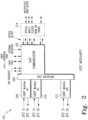
- FIG. 1is a block diagram of one embodiment of a system 100 using a modular wireless communications platform.
- System 100is a field configurable distributed antenna system (DAS) that provides bidirectional transport of a fixed portion of RF spectrum from an Internet Protocol (IP) gateway 101 to a remote antenna 108.
- IP gateway 101 and remote antenna 108system 100 includes a base station 103, a host unit 102, a transport mechanism 104, and a remote unit 106.
- Host unit 102, a modular host transceiver and remote unit 106, a modular remote radio head,work together to transmit and receive data to/from remote antennas.
- host unit 102provides the interface between a base station 101 a signal transport mechanism 104.
- Remote unit 106provides the interface between transport mechanism 104 and a remote antenna 108.
- signal transport mechanism 104is an optical fiber, and host unit 102 sends optical signals through the optical fiber to remote unit 106.
- base station 103performs baseband processing on IP data from IP gateway and places the IP data onto a channel.
- base station 103is an IEEE 802.16 compliant base station.
- base station 103may also meet the requirements of WiMax, WiBro, or a similar consortium.
- base station 103is an 800MHz or 1900MHz base station.
- the systemis a cellular/PCS system and base station 103 communicates with a base station controller.
- base station 103communicates with a voice/PSTN gateway.
- Base station 103also creates the protocol and modulation type for the channel. Base station 103 then converts the IP packetized data into an analog RF signal for transmission over antenna 108.
- Base station 103sends the RF signal to host unit 102.
- Host unit 102converts the RF signal for long distance high speed transmission over transport mechanism 104.
- Host unit 102sends the signal over transport mechanism 104, and the signal is received by remote unit 106.
- Remote unit 106converts the received signal back into an RF signal and transmits the signal over antenna 108 to consumer mobile devices.
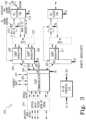
- FIG. 2illustrates a schematic diagram of one embodiment of a host unit 102 for use in a modular wireless communications platform.
- Host unit 102has a serial radio frequency (SeRF) communicator 202 that is coupled to a digital to analog radio frequency transceiver (DART) interface 204.
- DART interface 204has a plurality of DART connectors each of which is configured to receive a pluggable DART module 208. Further, DART connectors are configured to connect DART module 208 to SeRF communicator 202.
- DART interface 204is a common interface that is configured to allow communication between SeRF communicator 202 and different varieties of DART modules 208.
- DART interface 204allows multiple DART modules 208, 210, 212 to connect to a single SeRF communicator 202.
- DART interface 204is a passive host backplane to which SeRF communicator 202 also connects.
- DART interface 204has eight DART connectors for a DART module 208.
- DART interface 204is integrated with SeRF communicator 202.
- DART modules 208, 210, 212provide bi-directional conversion to/from analog RF signals from/to digital sampled RF.
- DART module 208receives an incoming analog RF signal from base station 103 and converts the analog signal to a digital signal for use by SeRF communicator 202.
- DART modules 208, 210, 212receive digital sampled RF data from SeRF communicator 202 and convert the data to analog RF for use by base station 103.
- Each DART module 208, 210, 212has a common communication interface for communication with SeRF communicator 202, and a RF processing portion that is exclusive to one frequency band and communication technology. Each DART module 208, 210, 212, therefore, converts to/from one analog RF to the digital signal used by SeRF communicator.
- DART module 208is designed to transmit 850 MHz cellular transmissions.
- DART module 210transmits 1900 MHz PCS signals.
- Some of the other options for DART modules 208, 210, 212include Nextel 800 band, Nextel 900 band, PCS full band, PCS half band, BRS, WiMax, and the European GSM 900, DCS 1800, and UMTS 2100.
- host unit 102is configurable to any of the above frequency bands and technologies as well as any new technologies or frequency bands that are developed. Host unit 102, once installed, is field configurable to transmit a variety desired by insertion of a different DART module. Additionally, since SeRF communicator 202 is configured to communicate with multiple different DART modules 208, 210, 212, a single host unit 102 can transmit/receive multiple frequency bands or technologies.
- SeRF communicator 202provides bi-directional conversion to/from a SeRF stream from/to a high speed optical serial data stream. In one direction, SeRF communicator 202 receives incoming SeRF streams from DART modules 208, 210, 212 and sends a serial optical data stream over transport mechanism 104 to remote unit 106. In the other direction, SeRF communicator 202 receives an optical serial data stream from a remote unit 106 and provides SeRF streams to DART modules 208, 210, 212. In one embodiment, the SeRF stream between DART module 208 and SeRF communicator is a parallel stream. In another embodiment, SeRF stream is a serial data stream.
- SeRF communicator 202also allows multiple DART modules 208, 210, 212 to operate in parallel. SeRF communicator 202 actively multiplexes the signals from each DART module 208, 210, 212 such that they are sent simultaneously over a single transport mechanism 104. To accomplish this, SeRF communicator 202 presents a clock signal to each DART module 208, 210, 212 to ensure synchronization.
- an optical multiplex module 214is optically coupled to SeRF communicator 202.
- Optical multiplex module 214performs multiplexing/demultiplexing of an optical serial data stream to/from SeRF communicator 202 over transport mechanism 104.
- optical multiplex module 214performs wavelength division multiplexing.
- transport mechanism 104is a wireless millimeter wave signal transceiver (e.g. E Band/70GHz radio).
- host unit 102sends optical signals to the millimeter wave transceiver which converts the optical signals into millimeter waves and transmits the millimeter waves to a similar millimeter wave transceiver connected to remote unit 106.
- transport mechanism 104is a microwave radio transceiver.
- transport mechanism 104is a T1 connection for transmission of IP data.
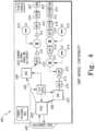
- FIG. 3is a schematic diagram of one embodiment of a remote unit 106 for use in a modular wireless communications platform.
- Remote unit 106has a SeRF communicator 302, a SeRF interface 304, at least one DART interface 306.
- DART modules 308, 309, 311, power amplified 310, duplexer/linear amplifier 312, and optical multiplex module 314are all installed in remote unit 106 which is connected to antenna 108.
- SeRF communicator 302is designed and performs similar to SeRF communicator 202 of host unit 102.
- DART modules 308, 309, 311have the same features and design options as DART modules 208, 210, 212 of host unit 102. There is a slight difference from host unit 102, however, in the manner in which SeRF communicator 302 and DART modules 308, 309, 311 are connected.
- SeRF communicator 302has a SeRF interface 304 which is used to link SeRF communicator to SeRF cables 305. SeRF cables 305 are used to allow DART modules 308, 309, 311 to be physically spaced from SeRF communicator 302 and from other DART modules.
- SeRF cables 305connect to DART interface 306.
- DART modules 308connected to DART interface 306 and communicate with SeRF communicator 302 through DART interface 306 over SeRF cables 305 and through SeRF interface 304.
- SeRF interface 304, and SeRF cables 305are eliminated and DART interface 306 is integrated into SeRF communicator 302.
- DART modules 308perform similar to DART module 208, except the ultimate destination/origination of the signals to/from DART modules 308 is antenna 108 and not base station 101 as in host unit 102.
- Optical multiplex module 314also performs similarly to optical multiplex module 214 of host unit 102.
- Power amplifier 310In the transmission direction, once a signal is converted to analog RF by DART module 308, the signal is sent through RF interface 322 (explained below) to power amplifier 310.
- Power amplifier 310amplifies the RF signal received from DART module 308 for output through duplexer/linear amplifier 312 to antenna 108. Similar to DART modules 308, 309, 311, power amplifier 310 is designed for a certain frequency band and technology. Power amplifier 310 is, therefore, removable and is plugged into a power amplifier connector on remote unit 106 which is configured to receive power amplifier 310. Power amplifier connector is configured to couple power amplifier to duplexer/linear amplifier 312 and to DART module 308. Power amplifier 310 also has an alarm and control line that is connected to DART interface 306 for communication to SeRF communicator 302.
- duplexer/linear amplifier 312provides duplexing of the signal which is necessary to connect transmit and receive signals to a common antenna.
- Duplexer/linear amplifier 312also provides low noise amplification of received signals and rms power detection of incident and reflected RF power in transmission signal. Similar to DART modules 308, 309, 311 and power amplifier 310, duplexer/linear amplifier 312 is frequency band and technology specific, and is removable.
- Duplexer/linear amplifier 312plugs into a connector in remote unit 106 configured to receive duplexer/linear amplifier 312. Furthermore, the connector is configured to couple duplexer/linear amplifier 312 to power amplifier 310 and to antenna 108.
- Duplexer/linear amplifier 312also has a control and alarm line that is connected to DART interface 320 for communication to SeRF communicator 302.
- the frequency band and technologyallow use of a single power amplifier 310 and duplexer/linear amplifier 318 by both DART module 308 and DART module 309.
- a RF interface 322is placed between power amplifier 310, duplexer/linear amplifier 312 and DART modules 305, 309.
- RF interface 322provides RF splitting/combining of the RF transmit and receive signals necessary to allow connection of two DART modules 308, 309 to a single power amplifier 310 and duplexer/linear amplifier 312.
- FIG. 4shows a schematic view of one embodiment of a DART module 400 for use in either host unit 102 or remote unit 106.
- DART module 400has an edge connector 402 for connection to a DART interface.
- DART module 400has two main signal paths; a transmission path 404 and a reception path 406.
- DART module 400forms parallel digital RF data from the incoming SeRF stream, if needed, at FPGA 403.
- FPGA 403is a logic device that is programmed to convert serial digital data into RF sampled data and programmed to convert RF sampled data into serial digital data.
- DART module 400then converts the digital signal to analog with digital to analog converter (DAC) 408.
- Transmission path 404continues as DART module 400 filters, amplifies and up-converts the analog signal for RF transmission with an assortment of filters 410, amplifiers 412, an oscillator 414, and an attenuator 416.
- the transmission pathexits DART module 400 at an SMA connector 420.
- the signalstravel in the opposite direction down reception path 406, where they are converted from analog to digital and sent to a SeRF communicator.
- First signalsare received at SMA connector 420.
- DART module 400then amplifies, down-converts, filters the incoming RF signal with a plurality of filters 410, amplifiers 412, oscillators 414, and attenuators 416.
- DART module 400then digitizes the signal with analog to digital converter 422.
- FPGA 403then forms a SeRF stream and provides the SeRF stream as parallel digital RF sampled data to a SeRF communicator.
- FIG. 5illustrates a schematic view of one embodiment of a SeRF communicator 500 for use in either host unit 102 or remote unit 106.
- Serial radio frequency communicator 500has a plurality of optical input/outputs 502, a clock 504, a field programmable gate array (FPGA) 506, a plurality of DART links 508, and a processor 510.
- SeRF communicator 500has eight (8) optical input/outputs 502.
- Optical input/outputs 502connect to optical fiber which is used as a transport mechanism, or optical fiber that links SeRF communicator 500 to an optical multiplexer or a millimeter waver or microwave transceiver.
- Optical input/outputs 502receiver high speed serial data transmission from another SeRF communicator.
- optical input/outputs 502receive Open Base Station Architecture (OBSAI) protocol data from a baseband unit.
- OBSAIOpen Base Station Architecture
- the signals received from optical input/outputs 502are transmitted at the same frequency which is set to match the OBSAI protocol.
- OBSAI datais stripped at the data link layer with a 8B/10B encoder to provide a good ones and zeros balance and remove approximately 20 percent of the OBSAID overhead.
- 16-bit filler wordsare used to provide a 24/25 ths transport ratio and match a 2.94 GBps transport speed to enable transport of OBSAI or SeRF data.
- the OBSAI protocol datais explained in more detail below with reference to Figure 6 .
- Optical input/outputs 206also conform to the optical small form-factor pluggable multi-source agreement. Alternatively, any frequency of signal or shape of connector could be used as is known in the art.
- SeRF communicator 500has eight (8) optical input/outputs and DART links 508 for 8 separate DART modules which transmit RF sampled data to/from DART modules.
- DART links 508 and corresponding connectors on a DART interfacecarry 6 slots of digitized RF payload for reading and writing DART FPGA registers from SeRF FGPA 506.
- Each slotconsists of 16 bits: 15 bits of digitized RF and 1 overhead bit used to transfer FPGA register data.
- the slotsare framed in groups of 6 16-bit words, with each slot repeating at the sampling rate of 15.36M samples per second.
- a "superframe" of 32 framesencapsulates the data payload and provides synchronization.
- DART links 508are16-bit parallel data streams.
- DART links 508are serial.
- FPGA 506has eight SERDES to serialize and de-serialize each data stream.
- each SERDESruns at either half rate or full rate and 50% efficiency such that the SERDES offers 6 RF slots of data.
- the SERDESrun at full rate, 100% efficiency and offer 12 RF slots of data.
- SeRF communicator 500receives incoming SeRF streams over DART links 508 from DART modules, assembles data frames, and sends an outgoing optical serial data stream through optical input/outputs 502.
- SeRF communicator 500receives an optical serial data stream from another SeRF communicator at optical input/outputs 502.
- SeRF communicator 500then disassembles the frames of the serial data stream, and provides SeRF streams over DART links 508 to DART modules.
- SeRF communicator 500also performs splitting and summing for digital simulcast, and provides a user interface for alarm, status, or configuration management.
- SeRF communicator 500also provides bi-directional conversion to/from OBSAI protocol data received at optical input/outputs 502 from/to RF sampled data for DART modules. Additionally, SeRF communicator 500 has at least one RJ-45 connector 216 for receiving IP packets. In one embodiment, RJ-45 connector 216 supports Gigabit Ethernet.
- host unit 102 and remote unit 106are configurable to perform more or less of the wireless processing of the RF signal.
- Host unit 102 and remote unit 106are configurable into three different functional configurations.
- the first configurationis illustrated in Figure 1 and has host unit 101 and remote unit 106 functioning as a range extender for base station 101. In this configuration, backhaul data is transmitted between host unit 102 and remote unit 106.
- the second configurationis illustrated in Figure 6 , and has fronthaul data transmitted between host unit 102 and remote unit 106. In this configuration remote unit 106 performs the functionality of a base station.
- the third configurationis illustrated in Figure 7 and has 'midhaul' data transmission between host unit 102 and remote unit 106.
- 'midhaul' datarefers to OBSAI protocol data or similar partially processed wireless signals.
- system 100shows one configuration for connection of host unit 102 and remote unit 106 in which remote unit 106 functions as a range extender.
- base station 103contains all necessary components to convert IP packets received from an Internet gateway into an analog bit stream for transmission over antenna 108. Except for needed amplification, the signal is ready for transmission over antenna 108 once sent by base station 103.
- Host device 102 and remote device 106do not perform any further processing on the data except what is required to send and receive the data over long range transmission.
- Host unit 102contains the components as illustrated in Figure 2 and receives the analog signal from base station 103 at the DART module matching the analog signal frequency band and technology.
- Host unit 102converts the signal and transmits the data over transport mechanism 104.
- Remote unit 106contains the components as shown in Figure 3 . Remote unit 106 receives the signal from transport mechanism 104 and sends the data to the DART module matching the frequency band and technology. The signal is then converted and transmitted over antenna 108 to mobile users.
- FIG. 6shows another configuration of a system 100 where base station functionality is performed at remote unit 106.
- This configurationprovides increased capacity to a network of antennas by allowing each remote unit 106 to function as a base station.
- IP datais not processed by a base station before sending to remote unit 106. Instead IP data is received at host unit 102 directly from IP gateway 101. IP data is received at an RJ-45 connector on SeRF communicator 202 of host unit 102. In this configuration, therefore, the signal does not travel through DART module 208, 210, 212 of host unit 102. The IP data is converted to a serial optical stream and transmitted over transport mechanism 104 to remote unit 106. Remote unit 106 receives the IP data at SeRF communicator 302.
- Remote Unit 106has a baseband unit 602 which is connected to a slot of DART interface 306.
- baseband unit 602is in fact a remote WiMax base station which replaces the functionality of base station 103 in the first configuration.
- SeRF communicator 302converts the packetized optical data received into 25-75 Mbps data and sends the data over to baseband unit 602.
- Baseband unit 602performs baseband processing to put the IP data onto a channel.
- Baseband unit 602also creates the protocol and modulation type for the channel.
- Baseband unit 602then converts the data to match the OBSAI protocol. This OBSAI data is sent back into an optical input/output 502 of SeRF communicator 302.
- SeRF communicator 302uses software to convert the OBSAI protocol data into digital RF sampled data and sends the digital RF data to DART module 308 for transmission over antenna 108.
- baseband unit 602converts IP data to/from common public radio interface (CPRI).
- CPRIcommon public radio interface
- any digital baseband protocol, including standard and proprietary protocols, or any software defined radio interfacecould be used by baseband unit 602 and SeRF communicator 302.
- FIG. 7illustrates yet another configuration of a system 100 in which remote unit 106 performs the functionality of a base station, and the baseband processing is performed prior to transmission by host unit 102.
- IP datais received at a baseband unit 702 which converts the IP data into data conforming to the OBSAI protocol.
- the OBSAI protocol datais sent to host unit 102 and OBSAI protocol data is transmitted over transport mechanism 104.
- the OBSAI conversionis done in SeRF 202 of host unit 102 before the serial data is transmitted to remote unit 106.
- DART module 208is not used at host unit 102, since the data has not been converted to RF yet.
- the OBSAI protocol datais received by remote device 106 at SeRF communicator 302.
- SeRF communicator 302converts the OBSAI protocol data into digital RF sampled data and interfaces with DART 308.
- DART 308converts the data to analog RF and the signal is sent over antenna 108.
- host unit 102 and remote unit 106have multiple input/outputs and can have multiple types of DART modules connected to each, host unit 102 and remote unit 106 are configured to multiplex different functional configurations through different input/outputs simultaneously.
- a first input/output of host unit 102 and remote unit 106function as a range extender for a base station.
- a second input/output of host unit 102 and remote unit 106function to transmit 'midhaul' data.
- a third input/output of host unit 102 and remote unit 106functions to transmit fronthaul data and remote unit 106 performs baseband processing upon the data.
- modular design of modular wireless communications protocolallows many different combinations of transport mechanisms, frequency bands, communication technologies, and processing functionality to operate simultaneously on the same host unit and remote unit.
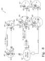
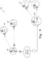
- FIG. 8illustrates one embodiment of a distributed base station system 800.
- System 800has a central node 801 having an IP gateway and a plurality of remote wireless communication stations 802, 804, 806, 808, 810, 812.
- Each remote station 802, 804, 806, 808, 810, 812includes a remote unit 814, 816, 818, 820, 822, 824, an antenna 826, and a router 828.
- remote unit 818 and remote unit 820are configured into a WiMax compatible base station.
- all remote units 814, 816, 818, 820, 822, 824are configured into PCS cellular base stations.
- any number of remote units 814, 816, 818, 820, 822, 824could be configured into a base station for any of the technology or frequency bands described with respect to system 100.
- Each remote station 802, 804, 806, 808, 810, 812functions similarly, except that they will vary based on the configuration of their respective remote unit 814, 816, 818, 820, 822, 824.
- Distributed base station system 800has many advantages over traditional centralized base station systems. For example, remote stations 806, 806 which are equipped with a base station do not need to transmit signals back to central node 801 for base station processing. Instead, when an RF signal is received via antenna 826 at remote station 806, for example, remote station 806 processes the RF signal with remote unit 818, which is configured as a base station. Processing the RF signal forms a second RF signal which is then routed toward the destination of the RF signal. In this embodiment, the RF signal received at remote unit 806 is from a first mobile device which is in communication with a second mobile device which is the destination of the second RF signal.
- the RF signalis received from a fixed internet user and the destination of the second RF signal is on the internet via IP gateway at central node 801.
- the second mobile deviceis within transmission range of remote station 812.
- routers 828 at remote stations 806, 810, 812route the second RF signal through remote station 810 to remote station 812.
- distributed base station system 800simplifies and speeds up the processing of wireless signals.
- each remote station 802, 804, 806, 808, 810, 812includes a router, a best path is found to the from the origination remote station to the destination remote station. This decreases the latency of communication transmission, and also reduces unnecessary network traffic.
- each remote station 802, 804, 806, 808, 810, 812obtains dedicated capacity to the system.
- Dedicated capacityrefers the allocation of an unvarying amount of bandwidth to each remote station 802, 804, 806, 808, 810, 812.
- each remote station 802, 804, 806, 808, 810, 812is allocated 25 Mbps of bandwidth. This is not possible in previous systems, because each remote station shares the capacity of a single central base station.
- remote stations 802, 804, 806, 808, 810, 812are set up in a ring configuration as shown in Figure 8 .
- the ring structureis advantageous, because a ring configuration allows multiple paths to be found to each remote station 802, 804, 806, 808, 810, 812. Thus, there are more options for a best path to be found to each remote device 802, 804, 806, 808, 810, 812, and congested areas are more easily avoided.
- remote stations 902, 904, 906, 908, 910, 912are arranged into tree configurations. Tree configurations are advantageous, because they reduce the complexity of the network and the amount of communication links that must be established. Tree configurations, however, still provide reduced latencies by allowing signals to be routed through the local hubs (e.g. remote station 902 and 908) and not requiring transmission to central hub 901.
- a plurality of remote stationsis set up in a daisy chain configuration.
- any combination of ring, tree, or daisy chain configurationscould be used to network a plurality of remote stations.
Landscapes
- Engineering & Computer Science (AREA)
- Computer Networks & Wireless Communication (AREA)
- Signal Processing (AREA)
- Physics & Mathematics (AREA)
- Electromagnetism (AREA)
- Mobile Radio Communication Systems (AREA)
- Arrangements For Transmission Of Measured Signals (AREA)
Description
- Technology is continually evolving as consumer needs change and new ideas are developed. Nowhere is this more apparent than in the wireless communications industry. Wireless communication technologies have changed drastically over the recent past and have affected many aspects of our daily lives. As new wireless technologies arc developed, companies must invest large amounts of time and resources to upgrade all their existing hardware so that it is compatible with the new technology. Often a change in one component of a system requires an update of the entire system.
- The infrastructure of a wireless communication system is commonly designed for a specific technology and a specific frequency band. Thus, once a service provider installs a particular infrastructure, a complete overhaul of a system is required to upgrade to a new technology or change to another frequency band. In addition, if a service provider would like to carry multiple frequency bands, the provider generally has to install a different set of hardware for each technology and frequency band carried. Thus, if the service provider carries four frequency bands of service for mobile customers; four different sets of hardware must be installed in each transmission and reception location.
- In addition to changes in technology, consumer demand for a particular service may change after a service is installed. For example, access points initially deployed using over-the-air repeaters or simulcast distributed antenna systems, may need to be replaced with full base stations to support the increased consumer demand. This again, will require major overhauls of existing infrastructure. Moreover, these changes occur not infrequently, are costly and are often necessary to keep pace with competitors within the industry.
- For the reasons stated above, and for other reasons stated below which will become apparent to those skilled in the art upon reading and understanding the present specification, there is a need in the art for a wireless communications platform that keeps pace with the rapid changes in wireless communications protocols.
WO2004/006602 describes a method for allocating information transfer capacity in a mobile communication system, and to a mobile communication system. In the method, the information transfer capacity is allocated to the user by forming a high capacity service site inside a cell of a base station by using a remote unit of a base station.US2004/0106435 describes an optical medium, such as fiber, that is tapped to provide an antenna port wherever radio service coverage is desired. Each antenna port is a bi-directional remote unit that receives a digital optical signal from a host unit and transforms the signal to a radio frequency signal for transmission by the remote unit. The remote unit receives radio frequency signals that are converted to digital signals and summed with signals from other remote units and converted to an optical signal for transmission to the host unit.- The above-mentioned problems of current systems are addressed by embodiments of the present invention and will be understood by reading and studying the following specification. The following summary is made by way of example and not by way of limitation. It is merely provided to aid the reader in understanding some of the aspects of the invention. The present invention thus provides a host unit, a distributed anteanna system and a remote unit according to the independent claims. Inone embodiment, a modular wireless communications platform is provided. The modular wireless communications platform has a modular host unit and a modular remote unit in communication with the modular host unit. The modular host unit has a serial radio frequency communicator configured to convert serial digital data into RF sampled data and configured to convert RF sampled data into serial digital data. The modular host unit also has an interface coupled to the serial radio frequency communicator and configured to allow transfer of the RF sampled data from the serial radio frequency communicator to a digital to analog radio frequency transceiver module. Likewise, the modular remote unit has a serial radio frequency communicator configured to convert serial digital data into RF sampled data and configured to convert RF sampled data into serial digital data. The modular remote unit also has an interface coupled to the serial radio frequency communicator and configured to allow transfer of the RF sampled data from the serial radio frequency communicator to a digital to analog radio frequency transceiver module.
- The present invention can be more easily understood and further advantages and uses thereof more readily apparent, when considered in view of the detailed description and the following figures in which:
Figure 1 is an illustration of one embodiment of a system using a modular wireless communications platform;Figure 2 illustrates a schematic view of one embodiment of a host unit for use in the system ofFigure 1 ;Figure 3 illustrates a schematic view of one embodiment of a remote unit for use in the system ofFigure 1 ;Figure 4 illustrates a schematic view of one embodiment of a digital to analog radio frequency transceiver module for use in either the host unit ofFigure 2 or the remote unit ofFigure 3 ;Figure 5 illustrates a schematic view of one embodiment of a serial radio frequency communicator for use in either the host unit ofFigure 2 or the remote unit ofFigure 3 ;Figure 6 illustrates another configuration of the system ofFigure 1 ;Figure 7 illustrates yet another configuration of the system ofFigure 1 ;Figure 8 illustrates one embodiment of a distributed base station system; andFigure 9 illustrates another embodiment of a distributed base station system.- In accordance with common practice, the various described features are not drawn to scale but are drawn to emphasize specific features relevant to the present invention. Reference characters denote like elements throughout Figures and text.
- In the following detailed description, reference is made to the accompanying drawings that form a part hereof, and in which is shown by way of illustration specific illustrative embodiments in which the device may be practiced. These embodiments are described in sufficient detail to enable those skilled in the art to practice the invention, and it is to be understood that other embodiments may be utilized and that logical, mechanical and electrical changes may be made without departing from the spirit and scope of the present invention. The following detailed description is, therefore, not to be taken in a limiting sense.
- The present apparatus is a modular wireless platform that enables a system facilitator to easily and inexpensively adapt their wireless system for use with different data transport mechanisms, frequency bands, communication technologies, and intelligence distribution. This modular platform is made up of a reconfigurable host unit and a reconfigurable remote unit designed for use in a system with a central node and a plurality of distributed antennas. The host unit is located near the central node and facilitates transmission/reception of information to/from the remote units which are located remotely with an accompanying antenna. The remote units function to transmit/receive transmissions from the host unit and transmit/receive wireless signals over accompanying antenna to mobile costumers.
- Host unit and remote unit have a modular design and defined interfaces that allow components to be removed and installed to adapt to the needs of the service providers. Both host and remote unit are designed around a serial radio frequency (SeRF) communicator and have a defined interface where different varieties of digital to analog radio frequency transceiver (DART) modules can be connected and disconnected. There are many different DART modules, and each DART module is designed for a particular technology and frequency band. Thus, technology and frequency band adjustments can be made by simply replacing the DART module in the host unit or remote unit. Additionally, host unit and remote unit are designed to allow different transport mechanisms between the host unit and remote unit. For example, the same host unit and remote unit that use fiber optic for inter-unit transmission can be adapted to use E Band wireless transmission instead of or concurrently with the fiber optic. Finally, wireless processing functionality can be placed all on a base station near the central node, or the functionality can be distributed throughout each of the remote units. The flexibility to modify the functionality of each remote unit allows the wireless platform to support centralized base stations and distributed base stations, either separately or concurrently.
Figure 1 is a block diagram of one embodiment of a system 100 using a modular wireless communications platform. System 100 is a field configurable distributed antenna system (DAS) that provides bidirectional transport of a fixed portion of RF spectrum from an Internet Protocol (IP)gateway 101 to aremote antenna 108. Along withIP gateway 101 andremote antenna 108, system 100 includes abase station 103, ahost unit 102, atransport mechanism 104, and aremote unit 106.Host unit 102, a modular host transceiver andremote unit 106, a modular remote radio head, work together to transmit and receive data to/from remote antennas. In this embodiment,host unit 102 provides the interface between a base station 101 asignal transport mechanism 104.Remote unit 106 provides the interface betweentransport mechanism 104 and aremote antenna 108. In this embodiment, signaltransport mechanism 104 is an optical fiber, andhost unit 102 sends optical signals through the optical fiber toremote unit 106.- In the transmission direction of transport,
base station 103 performs baseband processing on IP data from IP gateway and places the IP data onto a channel. In oneembodiment base station 103 is an IEEE 802.16 compliant base station. Optionally,base station 103 may also meet the requirements of WiMax, WiBro, or a similar consortium. In another embodiment,base station 103 is an 800MHz or 1900MHz base station. In yet another embodiment, the system is a cellular/PCS system andbase station 103 communicates with a base station controller. In still another embodiment,base station 103 communicates with a voice/PSTN gateway.Base station 103 also creates the protocol and modulation type for the channel.Base station 103 then converts the IP packetized data into an analog RF signal for transmission overantenna 108.Base station 103 sends the RF signal to hostunit 102.Host unit 102 converts the RF signal for long distance high speed transmission overtransport mechanism 104.Host unit 102 sends the signal overtransport mechanism 104, and the signal is received byremote unit 106.Remote unit 106 converts the received signal back into an RF signal and transmits the signal overantenna 108 to consumer mobile devices. Figure 2 illustrates a schematic diagram of one embodiment of ahost unit 102 for use in a modular wireless communications platform.Host unit 102 has a serial radio frequency (SeRF)communicator 202 that is coupled to a digital to analog radio frequency transceiver (DART)interface 204.DART interface 204 has a plurality of DART connectors each of which is configured to receive apluggable DART module 208. Further, DART connectors are configured to connectDART module 208 toSeRF communicator 202.DART interface 204 is a common interface that is configured to allow communication betweenSeRF communicator 202 and different varieties ofDART modules 208. Additionally,DART interface 204 allowsmultiple DART modules single SeRF communicator 202. In this embodiment,DART interface 204 is a passive host backplane to whichSeRF communicator 202 also connects. In this embodiment,DART interface 204 has eight DART connectors for aDART module 208. In another embodiment, instead of being a host backplane,DART interface 204 is integrated withSeRF communicator 202.DART modules DART module 208 receives an incoming analog RF signal frombase station 103 and converts the analog signal to a digital signal for use bySeRF communicator 202. In the otherdirection DART modules SeRF communicator 202 and convert the data to analog RF for use bybase station 103.- Each
DART module SeRF communicator 202, and a RF processing portion that is exclusive to one frequency band and communication technology. EachDART module DART module 208 is designed to transmit 850 MHz cellular transmissions. As another example,DART module 210 transmits 1900 MHz PCS signals. Some of the other options forDART modules Nextel 800 band,Nextel 900 band, PCS full band, PCS half band, BRS, WiMax, and theEuropean GSM 900, DCS 1800, and UMTS 2100. By allowing different varieties ofDART modules host unit 102 is configurable to any of the above frequency bands and technologies as well as any new technologies or frequency bands that are developed.Host unit 102, once installed, is field configurable to transmit a variety desired by insertion of a different DART module. Additionally, sinceSeRF communicator 202 is configured to communicate with multipledifferent DART modules single host unit 102 can transmit/receive multiple frequency bands or technologies. SeRF communicator 202 provides bi-directional conversion to/from a SeRF stream from/to a high speed optical serial data stream. In one direction,SeRF communicator 202 receives incoming SeRF streams fromDART modules transport mechanism 104 toremote unit 106. In the other direction,SeRF communicator 202 receives an optical serial data stream from aremote unit 106 and provides SeRF streams toDART modules DART module 208 and SeRF communicator is a parallel stream. In another embodiment, SeRF stream is a serial data stream.SeRF communicator 202 also allowsmultiple DART modules SeRF communicator 202 actively multiplexes the signals from eachDART module single transport mechanism 104. To accomplish this,SeRF communicator 202 presents a clock signal to eachDART module - In one embodiment, an
optical multiplex module 214 is optically coupled toSeRF communicator 202.Optical multiplex module 214 performs multiplexing/demultiplexing of an optical serial data stream to/fromSeRF communicator 202 overtransport mechanism 104. In this embodiment,optical multiplex module 214 performs wavelength division multiplexing. - In another embodiment,
transport mechanism 104 is a wireless millimeter wave signal transceiver (e.g. E Band/70GHz radio). In this embodiment,host unit 102 sends optical signals to the millimeter wave transceiver which converts the optical signals into millimeter waves and transmits the millimeter waves to a similar millimeter wave transceiver connected toremote unit 106. In yet another embodiment,transport mechanism 104 is a microwave radio transceiver. In still another embodiment,transport mechanism 104 is a T1 connection for transmission of IP data. Figure 3 is a schematic diagram of one embodiment of aremote unit 106 for use in a modular wireless communications platform.Remote unit 106 has aSeRF communicator 302, aSeRF interface 304, at least oneDART interface 306. In this embodiment,DART modules linear amplifier 312, andoptical multiplex module 314 are all installed inremote unit 106 which is connected toantenna 108.SeRF communicator 302 is designed and performs similar toSeRF communicator 202 ofhost unit 102. Likewise,DART modules DART modules host unit 102. There is a slight difference fromhost unit 102, however, in the manner in whichSeRF communicator 302 andDART modules remote unit 106,SeRF communicator 302 has aSeRF interface 304 which is used to link SeRF communicator toSeRF cables 305.SeRF cables 305 are used to allowDART modules SeRF communicator 302 and from other DART modules.SeRF cables 305 connect toDART interface 306.DART modules 308 connected toDART interface 306 and communicate withSeRF communicator 302 throughDART interface 306 overSeRF cables 305 and throughSeRF interface 304. In another embodiment,SeRF interface 304, andSeRF cables 305 are eliminated andDART interface 306 is integrated intoSeRF communicator 302.DART modules 308 perform similar toDART module 208, except the ultimate destination/origination of the signals to/fromDART modules 308 isantenna 108 and notbase station 101 as inhost unit 102.Optical multiplex module 314 also performs similarly tooptical multiplex module 214 ofhost unit 102.- In the transmission direction, once a signal is converted to analog RF by
DART module 308, the signal is sent through RF interface 322 (explained below) topower amplifier 310.Power amplifier 310 amplifies the RF signal received fromDART module 308 for output through duplexer/linear amplifier 312 toantenna 108. Similar toDART modules power amplifier 310 is designed for a certain frequency band and technology.Power amplifier 310 is, therefore, removable and is plugged into a power amplifier connector onremote unit 106 which is configured to receivepower amplifier 310. Power amplifier connector is configured to couple power amplifier to duplexer/linear amplifier 312 and toDART module 308.Power amplifier 310 also has an alarm and control line that is connected toDART interface 306 for communication toSeRF communicator 302. - Once the signal is amplified by
power amplifier 310, duplexer/linear amplifier 312 provides duplexing of the signal which is necessary to connect transmit and receive signals to a common antenna. Duplexer/linear amplifier 312 also provides low noise amplification of received signals and rms power detection of incident and reflected RF power in transmission signal. Similar toDART modules power amplifier 310, duplexer/linear amplifier 312 is frequency band and technology specific, and is removable. Duplexer/linear amplifier 312 plugs into a connector inremote unit 106 configured to receive duplexer/linear amplifier 312. Furthermore, the connector is configured to couple duplexer/linear amplifier 312 topower amplifier 310 and toantenna 108. Duplexer/linear amplifier 312 also has a control and alarm line that is connected to DART interface 320 for communication toSeRF communicator 302. In this embodiment, the frequency band and technology allow use of asingle power amplifier 310 and duplexer/linear amplifier 318 by bothDART module 308 andDART module 309. In this embodiment, aRF interface 322 is placed betweenpower amplifier 310, duplexer/linear amplifier 312 andDART modules RF interface 322 provides RF splitting/combining of the RF transmit and receive signals necessary to allow connection of twoDART modules single power amplifier 310 and duplexer/linear amplifier 312. Figure 4 shows a schematic view of one embodiment of aDART module 400 for use in eitherhost unit 102 orremote unit 106. There are multiple embodiments ofDART module 400 as described above, however, the common elements are described hereafter.DART module 400 has anedge connector 402 for connection to a DART interface.DART module 400 has two main signal paths; atransmission path 404 and areception path 406. For signals received from a SeRF communicator,DART module 400 forms parallel digital RF data from the incoming SeRF stream, if needed, atFPGA 403. In this embodiment,FPGA 403 is a logic device that is programmed to convert serial digital data into RF sampled data and programmed to convert RF sampled data into serial digital data.DART module 400 then converts the digital signal to analog with digital to analog converter (DAC) 408.Transmission path 404 continues asDART module 400 filters, amplifies and up-converts the analog signal for RF transmission with an assortment offilters 410,amplifiers 412, anoscillator 414, and anattenuator 416. The transmission path exitsDART module 400 at anSMA connector 420. The signals travel in the opposite direction downreception path 406, where they are converted from analog to digital and sent to a SeRF communicator. First signals are received atSMA connector 420.DART module 400 then amplifies, down-converts, filters the incoming RF signal with a plurality offilters 410,amplifiers 412,oscillators 414, andattenuators 416.DART module 400 then digitizes the signal with analog todigital converter 422.FPGA 403 then forms a SeRF stream and provides the SeRF stream as parallel digital RF sampled data to a SeRF communicator.Figure 5 illustrates a schematic view of one embodiment of aSeRF communicator 500 for use in eitherhost unit 102 orremote unit 106. Serialradio frequency communicator 500 has a plurality of optical input/outputs 502, aclock 504, a field programmable gate array (FPGA) 506, a plurality ofDART links 508, and aprocessor 510. In this embodiment,SeRF communicator 500 has eight (8) optical input/outputs 502. Optical input/outputs 502 connect to optical fiber which is used as a transport mechanism, or optical fiber that linksSeRF communicator 500 to an optical multiplexer or a millimeter waver or microwave transceiver. Optical input/outputs 502 receiver high speed serial data transmission from another SeRF communicator. In addition, optical input/outputs 502 receive Open Base Station Architecture (OBSAI) protocol data from a baseband unit. In one embodiment, to aid in the ability of optical input/outputs 502 to receive multiple data formats, the signals received from optical input/outputs 502 are transmitted at the same frequency which is set to match the OBSAI protocol. Also, OBSAI data is stripped at the data link layer with a 8B/10B encoder to provide a good ones and zeros balance and remove approximately 20 percent of the OBSAID overhead. Finally, 16-bit filler words are used to provide a 24/25ths transport ratio and match a 2.94 GBps transport speed to enable transport of OBSAI or SeRF data. The OBSAI protocol data is explained in more detail below with reference toFigure 6 . Optical input/outputs 206, also conform to the optical small form-factor pluggable multi-source agreement. Alternatively, any frequency of signal or shape of connector could be used as is known in the art.SeRF communicator 500 has eight (8) optical input/outputs andDART links 508 for 8 separate DART modules which transmit RF sampled data to/from DART modules.- In one embodiment,
DART links 508 and corresponding connectors on a DART interface carry 6 slots of digitized RF payload for reading and writing DART FPGA registers from SeRF FGPA 506. Each slot consists of 16 bits: 15 bits of digitized RF and 1 overhead bit used to transfer FPGA register data. The slots are framed in groups of 6 16-bit words, with each slot repeating at the sampling rate of 15.36M samples per second. A "superframe" of 32 frames encapsulates the data payload and provides synchronization. Thus, in thisembodiment DART links 508 are16-bit parallel data streams. In another embodiment,DART links 508 are serial. FPGA 506 has eight SERDES to serialize and de-serialize each data stream. Thus, there is one SERDES running for each DART link 508 and optical input/output 502. In this embodiment, each SERDES runs at either half rate or full rate and 50% efficiency such that the SERDES offers 6 RF slots of data. In another embodiment, there are half as many SERDES as DART modules. Thus, the SERDES run at full rate, 100% efficiency and offer 12 RF slots of data. - In one direction,
SeRF communicator 500 receives incoming SeRF streams overDART links 508 from DART modules, assembles data frames, and sends an outgoing optical serial data stream through optical input/outputs 502. In the other direction,SeRF communicator 500 receives an optical serial data stream from another SeRF communicator at optical input/outputs 502.SeRF communicator 500 then disassembles the frames of the serial data stream, and provides SeRF streams overDART links 508 to DART modules.SeRF communicator 500 also performs splitting and summing for digital simulcast, and provides a user interface for alarm, status, or configuration management.SeRF communicator 500 also provides bi-directional conversion to/from OBSAI protocol data received at optical input/outputs 502 from/to RF sampled data for DART modules. Additionally,SeRF communicator 500 has at least one RJ-45connector 216 for receiving IP packets. In one embodiment, RJ-45connector 216 supports Gigabit Ethernet. - Along with being configurable to communicate on different frequency band/sub-bands and with different technologies,
host unit 102 andremote unit 106 are configurable to perform more or less of the wireless processing of the RF signal.Host unit 102 andremote unit 106 are configurable into three different functional configurations. The first configuration is illustrated inFigure 1 and hashost unit 101 andremote unit 106 functioning as a range extender forbase station 101. In this configuration, backhaul data is transmitted betweenhost unit 102 andremote unit 106. The second configuration is illustrated inFigure 6 , and has fronthaul data transmitted betweenhost unit 102 andremote unit 106. In this configurationremote unit 106 performs the functionality of a base station. The third configuration is illustrated inFigure 7 and has 'midhaul' data transmission betweenhost unit 102 andremote unit 106. In this embodiment, 'midhaul' data refers to OBSAI protocol data or similar partially processed wireless signals. Each of the three configurations will now be explained in further detail. - Referring back to
Figure 1 , system 100 shows one configuration for connection ofhost unit 102 andremote unit 106 in whichremote unit 106 functions as a range extender. In this option,base station 103 contains all necessary components to convert IP packets received from an Internet gateway into an analog bit stream for transmission overantenna 108. Except for needed amplification, the signal is ready for transmission overantenna 108 once sent bybase station 103.Host device 102 andremote device 106 do not perform any further processing on the data except what is required to send and receive the data over long range transmission.Host unit 102 contains the components as illustrated inFigure 2 and receives the analog signal frombase station 103 at the DART module matching the analog signal frequency band and technology.Host unit 102 converts the signal and transmits the data overtransport mechanism 104.Remote unit 106 contains the components as shown inFigure 3 .Remote unit 106 receives the signal fromtransport mechanism 104 and sends the data to the DART module matching the frequency band and technology. The signal is then converted and transmitted overantenna 108 to mobile users. Figure 6 shows another configuration of a system 100 where base station functionality is performed atremote unit 106. This configuration provides increased capacity to a network of antennas by allowing eachremote unit 106 to function as a base station. In this embodiment of system 100, IP data is not processed by a base station before sending toremote unit 106. Instead IP data is received athost unit 102 directly fromIP gateway 101. IP data is received at an RJ-45 connector onSeRF communicator 202 ofhost unit 102. In this configuration, therefore, the signal does not travel throughDART module host unit 102. The IP data is converted to a serial optical stream and transmitted overtransport mechanism 104 toremote unit 106.Remote unit 106 receives the IP data atSeRF communicator 302.Remote Unit 106, in this embodiment, has abaseband unit 602 which is connected to a slot ofDART interface 306. In this configuration,baseband unit 602 is in fact a remote WiMax base station which replaces the functionality ofbase station 103 in the first configuration.SeRF communicator 302 converts the packetized optical data received into 25-75 Mbps data and sends the data over tobaseband unit 602.Baseband unit 602 performs baseband processing to put the IP data onto a channel.Baseband unit 602 also creates the protocol and modulation type for the channel.Baseband unit 602 then converts the data to match the OBSAI protocol. This OBSAI data is sent back into an optical input/output 502 ofSeRF communicator 302.SeRF communicator 302 uses software to convert the OBSAI protocol data into digital RF sampled data and sends the digital RF data toDART module 308 for transmission overantenna 108. In another embodiment,baseband unit 602 converts IP data to/from common public radio interface (CPRI). Alternatively, any digital baseband protocol, including standard and proprietary protocols, or any software defined radio interface could be used bybaseband unit 602 andSeRF communicator 302.Figure 7 illustrates yet another configuration of a system 100 in whichremote unit 106 performs the functionality of a base station, and the baseband processing is performed prior to transmission byhost unit 102. In this embodiment, IP data is received at abaseband unit 702 which converts the IP data into data conforming to the OBSAI protocol. Alternatively, any of the protocols listed with respect toFigure 6 could be used. The OBSAI protocol data is sent to hostunit 102 and OBSAI protocol data is transmitted overtransport mechanism 104. In another embodiment, the OBSAI conversion is done inSeRF 202 ofhost unit 102 before the serial data is transmitted toremote unit 106. Here again,DART module 208 is not used athost unit 102, since the data has not been converted to RF yet. The OBSAI protocol data is received byremote device 106 atSeRF communicator 302.SeRF communicator 302 converts the OBSAI protocol data into digital RF sampled data and interfaces withDART 308.DART 308 converts the data to analog RF and the signal is sent overantenna 108.- Since
host unit 102 andremote unit 106 have multiple input/outputs and can have multiple types of DART modules connected to each,host unit 102 andremote unit 106 are configured to multiplex different functional configurations through different input/outputs simultaneously. Thus, in one embodiment, a first input/output ofhost unit 102 andremote unit 106 function as a range extender for a base station. A second input/output ofhost unit 102 andremote unit 106 function to transmit 'midhaul' data. At the same time a third input/output ofhost unit 102 andremote unit 106 functions to transmit fronthaul data andremote unit 106 performs baseband processing upon the data. - The modular design of modular wireless communications protocol allows many different combinations of transport mechanisms, frequency bands, communication technologies, and processing functionality to operate simultaneously on the same host unit and remote unit.
- Placing a base station at a remote wireless communication stations such as described with the configuration of
Figure 6 allows service providers to set up a distributed base station system.Figure 8 illustrates one embodiment of a distributedbase station system 800.System 800 has acentral node 801 having an IP gateway and a plurality of remotewireless communication stations remote station remote unit antenna 826, and arouter 828. In this embodiment,remote unit 818 andremote unit 820 are configured into a WiMax compatible base station. In another embodiment, allremote units remote units remote station remote unit - Distributed
base station system 800 has many advantages over traditional centralized base station systems. For example,remote stations central node 801 for base station processing. Instead, when an RF signal is received viaantenna 826 atremote station 806, for example,remote station 806 processes the RF signal withremote unit 818, which is configured as a base station. Processing the RF signal forms a second RF signal which is then routed toward the destination of the RF signal. In this embodiment, the RF signal received atremote unit 806 is from a first mobile device which is in communication with a second mobile device which is the destination of the second RF signal. In another embodiment, the RF signal is received from a fixed internet user and the destination of the second RF signal is on the internet via IP gateway atcentral node 801. In this embodiment, the second mobile device is within transmission range ofremote station 812. Thus, after processing byremote unit 818 atremote station 806,routers 828 atremote stations remote station 810 toremote station 812. Thus, distributedbase station system 800 simplifies and speeds up the processing of wireless signals. - In addition, there are many other advantages of a distributed base station system. For example, since each
remote station remote station remote station remote station remote station - In one embodiment,
remote stations Figure 8 . The ring structure is advantageous, because a ring configuration allows multiple paths to be found to eachremote station remote device Figure 9 ,remote stations remote station 902 and 908) and not requiring transmission to central hub 901. - In yet another embodiment, a plurality of remote stations is set up in a daisy chain configuration. Alternatively, any combination of ring, tree, or daisy chain configurations could be used to network a plurality of remote stations.
- Although specific embodiments have been illustrated and described herein, it will be appreciated by those of ordinary skill in the art that any arrangement, which is calculated to achieve the same purpose, may be substituted for the specific embodiment shown. This application is intended to cover any adaptations or variations of the present invention. Therefore, it is manifestly intended that this invention be limited only by the claims
Claims (13)
- A host unit (102) of a distributed antenna system (100), wherein the host unit (102) is configured to be coupled to a base station (103), the host unit (102) comprising:at least one of:a baseband processor (702) configured to receive Internet Protocol (IP) data from an IP gateway (101), wherein the baseband processor (702) is configured to perform baseband processing to place the IP data onto a channel, wherein the baseband processor (702) is configured to convert between IP data and baseband, digital data; oran interface configured to communicate baseband, digital data with a base station (103);the host unit (102) further comprising:an radio frequency (RF) module (208, 210, 212) configured to communicate with a base station (103) using RF signals configured for communication over an antenna (108), the RF module (208, 210, 212) configured to convert between the RF signals configured for communication over an antenna (108) and RF sampled data; anda serial interface (202) configured to convert between the RF sampled data and one or more serial data streams, wherein the serial interface (202) is further configured to convert between the baseband, digital data and one or more second serial data streams;wherein the host unit (102) is configured to provide the one or more serial data streams and the one or more second serial data streams to a communication medium (104) for transmission to a remote unit (106) of the distributed antenna system (100).
- The host unit (102) of claim 1, wherein the host unit (102) comprises both the baseband processor (702) and the interface.
- The host unit (102) of claim 1, wherein the host unit (102) includes:the baseband processor (702) and does not include the interface; orthe interface and does not include the baseband processor (702).
- A distributed antenna system (100) including the host unit (102) of any of claims 1-3, the distributed antenna system (100) further comprising:the remote unit (106), coupled to the host unit (102) over a communication medium (104), wherein the remote unit (106) is configured to receive the one or more serial data streams and the one or more second serial data streams from the communication medium (104);the remote unit (106) including:a serial interface (302), coupled to the communication medium (104), the serial interface (302) configured to convert between the one or more serial data streams and RF sampled data, wherein the serial interface (302) further configured to convert between the one or more second serial data streams and RF sampled data;an RF module (308, 309, 311), coupled to the serial interface (302), the RF module (308, 309, 311) configured to convert between the RF sampled data and an RF signal; andan antenna (108) coupled to the RF module (308, 309, 311), wherein the remote unit (106) is configured to communicate RF signals with one or more mobile devices using the antenna (108).
- A method for radio frequency (RF) communications in a distributed antenna system, wherein the distributed antenna system includes a host unit communicatively coupled to and located remotely from a remote unit, wherein the host unit of the distributed antenna system is configured to be coupled to a base station, the method comprising:receiving one or more first serial data streams and one or more second serial data streams at the host unit of the distributed antenna system from the remote unit via a communication medium;converting, with a serial interface of the host unit, the one or more first serial data streams to one or more baseband, digital signals;converting, with the serial interface of the host unit, the one or more second serial data streams to RF sampled data;converting, with an RF module of the host unit, the RF sampled data to one or more RF signals; andtransmitting, via the RF module of the host unit, the one or more RF signals to the base station;wherein the method further comprises at least one of:generating, with a baseband processor of the host unit, Internet Protocol (IP) data from at least some of the one or more baseband, digital signals; ortransmitting, via an interface of the host unit, at least some of the one or more baseband, digital signals from the host unit to the base station.
- The method of claim 5, further comprising:receiving the one or more third serial data streams at the host unit from the remote unit via the communication medium;converting the one or more serial data streams to IP data at the host unit; andtransmitting IP data from the host unit to an IP gateway.
- The method of claim 5, further comprising:receiving RF signals at a remote unit of the distributed antenna system from one or more mobile devices via an antenna;converting, with an RF interface of the remote unit, the received RF signals into RF sampled data;converting, with a serial interface of the remote unit, at least some of the RF sampled data to one or more baseband, digital signals;generating, with the serial interface of the remote unit, the one or more first serial data streams from the one or more baseband, digital signals;generating, with the serial interface of the remote unit, the one or more second serial data streams from at least some of the RF sampled data;transmitting the one or more first serial data streams and the one or more second serial data streams to the host unit over the communication medium.
- The method of claim 5, further comprising:generating, with a baseband processor of the remote unit, Internet Protocol (IP) data from at least some of the baseband, digital data;generating, with a serial interface of the remote unit, one or more third serial data streams from the IP data;transmitting the one or more third serial data streams to a host unit of the distributed antenna system over a communication medium.
- The method of claim 5, wherein the method comprises both generating IP data from the one or more baseband, digital signals and transmitting at least some of the one or more baseband, digital signals from the host unit to the base station.
- A remote unit (106) of a distributed antenna system (100), wherein the distributed antenna system (100) includes a host unit (102) and the remote unit (106), wherein the host unit (102) of the distributed antenna system (100) is configured to be coupled to a base station (103), the remote unit (106) comprising:an RF interface configured to receive radio frequency (RF) signals from one or more mobile devices via an antenna and convert between the RF signals and RF sampled data;a serial interface (302) configured convert between RF sampled data and baseband, digital data;a baseband processor (602) configured to convert between baseband, digital data and Internet Protocol (IP) data; andwherein the serial interface (302) is further configured to:convert between IP data and one or more first serial data streams;convert between RF sampled data and one or more second serial data streams; andtransmit the one or more first serial data streams and the one or more second serial data streams to the host unit (102) over a communication medium (104).
- The remote unit (106) of claim 10, wherein the RF interface includes a first RF module (308) configured to communicate with mobile devices using a first frequency band and a second RF module (309) configured to communicate with mobile devices using a second frequency band.
- A distributed antenna system (100) including the remote unit (106) of any of claims 10-11, the distributed antenna system (100) further comprising:
the host unit (102), coupled to the remote unit (106) over a communication medium (104), wherein the host unit (102) to receive the one or more first serial data streams and the one or more second serial data streams from the communication medium (104), wherein the host unit (102) comprises:a serial interface (202) configured to convert between the one or more first serial data streams and IP data and to convert between the one or more second serial data streams and RF sampled data;a first interface configured to communicate the IP data to an IP gateway (101); andan RF module (208, 210, 212) configured to communicate with a base station (103) using RF signals, the RF module (208, 210, 212) configured to convert between the RF sampled data and RF signals. - The distributed antenna system (100) of claim 12, wherein the serial interface (302) of the remote unit (106) is further configured to convert between at least some of the baseband, digital data and one or more third serial data streams, wherein the serial interface (202) of the host unit (102) is configured to convert the one or more third serial data streams to baseband, digital signals,
wherein the host unit (102) further comprises at least one of:a baseband processor (702) configured to generate IP data from at least some of the one or more baseband, digital signals; ora second interface configured to transmit at least some of the one or more baseband, digital signals from the host unit (102) to the base station (103).
Applications Claiming Priority (4)
| Application Number | Priority Date | Filing Date | Title |
|---|---|---|---|
| US200762725107P | 2007-01-25 | 2007-01-25 | |
| US11/627,251US8737454B2 (en) | 2007-01-25 | 2007-01-25 | Modular wireless communications platform |
| PCT/US2008/052023WO2008092067A2 (en) | 2007-01-25 | 2008-01-25 | Modular wireless communications platform |
| EP08728283.6AEP2137989B1 (en) | 2007-01-25 | 2008-01-25 | Modular wireless communications platform |
Related Parent Applications (1)
| Application Number | Title | Priority Date | Filing Date |
|---|---|---|---|
| EP08728283.6ADivisionEP2137989B1 (en) | 2007-01-25 | 2008-01-25 | Modular wireless communications platform |
Publications (2)
| Publication Number | Publication Date |
|---|---|
| EP3462807A1 EP3462807A1 (en) | 2019-04-03 |
| EP3462807B1true EP3462807B1 (en) | 2023-05-17 |
Family
ID=39645183
Family Applications (2)
| Application Number | Title | Priority Date | Filing Date |
|---|---|---|---|
| EP18204572.4AActiveEP3462807B1 (en) | 2007-01-25 | 2008-01-25 | Modular wireless communications platform |
| EP08728283.6AActiveEP2137989B1 (en) | 2007-01-25 | 2008-01-25 | Modular wireless communications platform |
Family Applications After (1)
| Application Number | Title | Priority Date | Filing Date |
|---|---|---|---|
| EP08728283.6AActiveEP2137989B1 (en) | 2007-01-25 | 2008-01-25 | Modular wireless communications platform |
Country Status (5)
| Country | Link |
|---|---|
| US (4) | US8737454B2 (en) |
| EP (2) | EP3462807B1 (en) |
| KR (2) | KR101480581B1 (en) |
| CN (2) | CN101663915B (en) |
| WO (1) | WO2008092067A2 (en) |
Families Citing this family (139)
| Publication number | Priority date | Publication date | Assignee | Title |
|---|---|---|---|---|
| US8380143B2 (en) | 2002-05-01 | 2013-02-19 | Dali Systems Co. Ltd | Power amplifier time-delay invariant predistortion methods and apparatus |
| US8811917B2 (en) | 2002-05-01 | 2014-08-19 | Dali Systems Co. Ltd. | Digital hybrid mode power amplifier system |
| CN102017553B (en) | 2006-12-26 | 2014-10-15 | 大力系统有限公司 | Method and system for baseband predistortion linearization in a multi-channel broadband communication system |
| US8737454B2 (en) | 2007-01-25 | 2014-05-27 | Adc Telecommunications, Inc. | Modular wireless communications platform |
| US8254850B2 (en)* | 2008-06-11 | 2012-08-28 | Adc Telecommunications, Inc. | Communication module component assemblies |
| US20090310972A1 (en)* | 2008-06-11 | 2009-12-17 | Adc Telecommunications, Inc. | Circuit card subassemblies for interconnection of electronic components |
| US20100081422A1 (en)* | 2008-09-29 | 2010-04-01 | Broadcom Corporation | Multiband communication device with communication control and methods for use therewith |
| ES2350542B1 (en)* | 2008-12-12 | 2011-11-16 | Vodafone España, S.A.U. | SYSTEM AND ANTENNA FOR RADIO ACCESS NETWORKS. |
| CN102292949B (en)* | 2009-01-13 | 2015-07-15 | Adc长途电讯有限公司 | Systems and methods for improved digital RF transmission in distributed antenna systems |
| US8213401B2 (en) | 2009-01-13 | 2012-07-03 | Adc Telecommunications, Inc. | Systems and methods for IP communication over a distributed antenna system transport |
| US8346278B2 (en) | 2009-01-13 | 2013-01-01 | Adc Telecommunications, Inc. | Systems and methods for mobile phone location with digital distributed antenna systems |
| USRE47466E1 (en) | 2009-01-13 | 2019-06-25 | Commscope Technologies Llc | Systems and methods for IP communication over a distributed antenna system transport |
| EP2392075A4 (en)* | 2009-01-27 | 2013-08-07 | Adc Telecommunications Inc | Method and apparatus for digitally equalizing a signal in a distributed antenna system |
| US9673904B2 (en) | 2009-02-03 | 2017-06-06 | Corning Optical Communications LLC | Optical fiber-based distributed antenna systems, components, and related methods for calibration thereof |
| CN102396171B (en) | 2009-02-03 | 2015-09-30 | 康宁光缆系统有限责任公司 | Based on the distributing antenna system of optical fiber, assembly and the correlation technique for monitoring and configure distributing antenna system based on optical fiber, assembly |
| CN102369678B (en) | 2009-02-03 | 2015-08-19 | 康宁光缆系统有限责任公司 | Optical fiber based distributed antenna systems, assemblies and related methods for calibrating optical fiber based distributed antenna systems, assemblies |
| US8346091B2 (en)* | 2009-04-29 | 2013-01-01 | Andrew Llc | Distributed antenna system for wireless network systems |
| US8280259B2 (en) | 2009-11-13 | 2012-10-02 | Corning Cable Systems Llc | Radio-over-fiber (RoF) system for protocol-independent wired and/or wireless communication |
| CN102076024B (en)* | 2009-11-24 | 2014-11-05 | 华为技术有限公司 | Base station, network system and implementation method |
| US8275265B2 (en) | 2010-02-15 | 2012-09-25 | Corning Cable Systems Llc | Dynamic cell bonding (DCB) for radio-over-fiber (RoF)-based networks and communication systems and related methods |
| US8681917B2 (en) | 2010-03-31 | 2014-03-25 | Andrew Llc | Synchronous transfer of streaming data in a distributed antenna system |
| US8837940B2 (en) | 2010-04-14 | 2014-09-16 | Adc Telecommunications, Inc. | Methods and systems for distributing fiber optic telecommunication services to local areas and for supporting distributed antenna systems |
| DE102010018492B4 (en) | 2010-04-28 | 2011-12-08 | Andrew Wireless Systems Gmbh | Interface module for a unit of an antenna distribution system and antenna distribution system |
| US20110268446A1 (en) | 2010-05-02 | 2011-11-03 | Cune William P | Providing digital data services in optical fiber-based distributed radio frequency (rf) communications systems, and related components and methods |
| US9525488B2 (en) | 2010-05-02 | 2016-12-20 | Corning Optical Communications LLC | Digital data services and/or power distribution in optical fiber-based distributed communications systems providing digital data and radio frequency (RF) communications services, and related components and methods |
| US8472579B2 (en)* | 2010-07-28 | 2013-06-25 | Adc Telecommunications, Inc. | Distributed digital reference clock |
| WO2012024247A1 (en) | 2010-08-16 | 2012-02-23 | Corning Cable Systems Llc | Remote antenna clusters and related systems, components, and methods supporting digital data signal propagation between remote antenna units |
| KR101835254B1 (en)* | 2010-08-17 | 2018-03-06 | 달리 시스템즈 씨오. 엘티디. | Neutral host architecture for a distributed antenna system |
| CN103597807B (en) | 2010-09-14 | 2015-09-30 | 大理系统有限公司 | Remotely reconfigurable distributed antenna system and method |
| US9252874B2 (en) | 2010-10-13 | 2016-02-02 | Ccs Technology, Inc | Power management for remote antenna units in distributed antenna systems |
| US8532242B2 (en) | 2010-10-27 | 2013-09-10 | Adc Telecommunications, Inc. | Distributed antenna system with combination of both all digital transport and hybrid digital/analog transport |
| KR101874655B1 (en) | 2011-02-07 | 2018-07-04 | 달리 시스템즈 씨오. 엘티디. | Daisy-chained ring of remote units for a distributed antenna system |
| EP2678972B1 (en) | 2011-02-21 | 2018-09-05 | Corning Optical Communications LLC | Providing digital data services as electrical signals and radio-frequency (rf) communications over optical fiber in distributed communications systems, and related components and methods |
| EP2692064B1 (en)* | 2011-03-28 | 2021-01-13 | Telefonaktiebolaget LM Ericsson (publ) | Remote radio device |
| WO2012148940A1 (en) | 2011-04-29 | 2012-11-01 | Corning Cable Systems Llc | Systems, methods, and devices for increasing radio frequency (rf) power in distributed antenna systems |
| WO2012148938A1 (en) | 2011-04-29 | 2012-11-01 | Corning Cable Systems Llc | Determining propagation delay of communications in distributed antenna systems, and related components, systems and methods |
| US8743718B2 (en) | 2011-06-21 | 2014-06-03 | Adc Telecommunications, Inc. | End-to-end delay management for distributed communications networks |
| KR101971584B1 (en)* | 2011-06-29 | 2019-04-23 | 콤스코프 커넥티비티 엘엘씨 | Evolved distributed antenna system |
| CN103733664B (en) | 2011-07-11 | 2017-10-24 | 康普技术有限责任公司 | Method and apparatus for managing a distributed antenna system |
| US8238318B1 (en) | 2011-08-17 | 2012-08-07 | CBF Networks, Inc. | Intelligent backhaul radio |
| US10764891B2 (en) | 2011-08-17 | 2020-09-01 | Skyline Partners Technology Llc | Backhaul radio with advanced error recovery |
| US8928542B2 (en) | 2011-08-17 | 2015-01-06 | CBF Networks, Inc. | Backhaul radio with an aperture-fed antenna assembly |
| US9049611B2 (en) | 2011-08-17 | 2015-06-02 | CBF Networks, Inc. | Backhaul radio with extreme interference protection |
| US8422540B1 (en) | 2012-06-21 | 2013-04-16 | CBF Networks, Inc. | Intelligent backhaul radio with zero division duplexing |
| US9713019B2 (en) | 2011-08-17 | 2017-07-18 | CBF Networks, Inc. | Self organizing backhaul radio |
| US10051643B2 (en) | 2011-08-17 | 2018-08-14 | Skyline Partners Technology Llc | Radio with interference measurement during a blanking interval |
| US10708918B2 (en) | 2011-08-17 | 2020-07-07 | Skyline Partners Technology Llc | Electronic alignment using signature emissions for backhaul radios |
| US8761100B2 (en) | 2011-10-11 | 2014-06-24 | CBF Networks, Inc. | Intelligent backhaul system |
| US8982772B2 (en) | 2011-08-17 | 2015-03-17 | CBF Networks, Inc. | Radio transceiver with improved radar detection |
| US8385305B1 (en) | 2012-04-16 | 2013-02-26 | CBF Networks, Inc | Hybrid band intelligent backhaul radio |
| US8467363B2 (en) | 2011-08-17 | 2013-06-18 | CBF Networks, Inc. | Intelligent backhaul radio and antenna system |
| US10716111B2 (en) | 2011-08-17 | 2020-07-14 | Skyline Partners Technology Llc | Backhaul radio with adaptive beamforming and sample alignment |
| US9474080B2 (en) | 2011-08-17 | 2016-10-18 | CBF Networks, Inc. | Full duplex backhaul radio with interference measurement during a blanking interval |
| US10548132B2 (en) | 2011-08-17 | 2020-01-28 | Skyline Partners Technology Llc | Radio with antenna array and multiple RF bands |
| US8989762B1 (en) | 2013-12-05 | 2015-03-24 | CBF Networks, Inc. | Advanced backhaul services |
| US8502733B1 (en) | 2012-02-10 | 2013-08-06 | CBF Networks, Inc. | Transmit co-channel spectrum sharing |
| AU2012302074B2 (en) | 2011-08-29 | 2017-02-16 | Commscope Technologies Llc | Configuring a distributed antenna system |
| EP2566291B1 (en)* | 2011-09-05 | 2018-06-27 | Alcatel Lucent | Apparatus, Method, and Computer Program for a Remote Unit and a Central Unit |
| US9060382B2 (en)* | 2011-10-13 | 2015-06-16 | Broadcom Corporation | Split architecture remote radio |
| US8837564B2 (en)* | 2011-10-14 | 2014-09-16 | Broadcom Corporation | Multi gigabit modem for mmWave point to point links |
| US8693342B2 (en)* | 2011-10-28 | 2014-04-08 | Adc Telecommunications, Inc. | Distributed antenna system using time division duplexing scheme |
| WO2013082042A1 (en)* | 2011-11-28 | 2013-06-06 | Dali Systems Co. Ltd | Distributed antenna system and method for bandwidth compression and transport of noncontiguous signal frequency blocks |
| US10110307B2 (en) | 2012-03-02 | 2018-10-23 | Corning Optical Communications LLC | Optical network units (ONUs) for high bandwidth connectivity, and related components and methods |
| WO2013162988A1 (en) | 2012-04-25 | 2013-10-31 | Corning Cable Systems Llc | Distributed antenna system architectures |
| KR101426339B1 (en)* | 2012-05-24 | 2014-08-13 | 유니트론 주식회사 | UTP Cable Scalable Remote Radio Head and In-Building Repeater System including the Remote Radio Head |
| US9107086B2 (en) | 2012-07-20 | 2015-08-11 | Adc Telecommunications, Inc. | Integration panel |
| WO2014024192A1 (en) | 2012-08-07 | 2014-02-13 | Corning Mobile Access Ltd. | Distribution of time-division multiplexed (tdm) management services in a distributed antenna system, and related components, systems, and methods |
| DE202013012858U1 (en) | 2012-08-09 | 2021-05-07 | Axel Wireless Ltd. | Capacity-centered digital distributed antenna system |
| USD704174S1 (en) | 2012-08-14 | 2014-05-06 | CBF Networks, Inc. | Intelligent backhaul radio with symmetric wing radome |
| EP2713436A1 (en)* | 2012-09-28 | 2014-04-02 | Alcatel Lucent | Module active antenna unit |
| US9913147B2 (en) | 2012-10-05 | 2018-03-06 | Andrew Wireless Systems Gmbh | Capacity optimization sub-system for distributed antenna system |
| AU2013338583B2 (en) | 2012-10-31 | 2017-08-31 | Commscope Technologies Llc | Digital baseband transport in telecommunications distribution systems |
| US9455784B2 (en) | 2012-10-31 | 2016-09-27 | Corning Optical Communications Wireless Ltd | Deployable wireless infrastructures and methods of deploying wireless infrastructures |
| US9647758B2 (en) | 2012-11-30 | 2017-05-09 | Corning Optical Communications Wireless Ltd | Cabling connectivity monitoring and verification |
| US9414399B2 (en) | 2013-02-07 | 2016-08-09 | Commscope Technologies Llc | Radio access networks |
| US9380466B2 (en)* | 2013-02-07 | 2016-06-28 | Commscope Technologies Llc | Radio access networks |
| CA2914104C (en) | 2013-02-22 | 2022-12-13 | Adc Telecommunications, Inc. | Master reference for base station network interface sourced from distributed antenna system |
| CA2901666A1 (en) | 2013-02-22 | 2014-08-28 | Adc Telecommunications, Inc. | Universal remote radio head |
| US9955361B2 (en) | 2013-02-26 | 2018-04-24 | Dali Systems Co., Ltd. | Method and system for WI-FI data transmission |
| CN105452951B (en) | 2013-06-12 | 2018-10-19 | 康宁光电通信无线公司 | Voltage type optical directional coupler |
| WO2014199380A1 (en) | 2013-06-12 | 2014-12-18 | Corning Optical Communications Wireless, Ltd. | Time-division duplexing (tdd) in distributed communications systems, including distributed antenna systems (dass) |
| US9247543B2 (en) | 2013-07-23 | 2016-01-26 | Corning Optical Communications Wireless Ltd | Monitoring non-supported wireless spectrum within coverage areas of distributed antenna systems (DASs) |
| US9661781B2 (en) | 2013-07-31 | 2017-05-23 | Corning Optical Communications Wireless Ltd | Remote units for distributed communication systems and related installation methods and apparatuses |
| US9385810B2 (en) | 2013-09-30 | 2016-07-05 | Corning Optical Communications Wireless Ltd | Connection mapping in distributed communication systems |
| US9787457B2 (en)* | 2013-10-07 | 2017-10-10 | Commscope Technologies Llc | Systems and methods for integrating asynchronous signals in distributed antenna system with direct digital interface to base station |
| US9847816B2 (en) | 2013-12-19 | 2017-12-19 | Dali Systems Co. Ltd. | Digital transport of data over distributed antenna network |
| US20170250927A1 (en) | 2013-12-23 | 2017-08-31 | Dali Systems Co. Ltd. | Virtual radio access network using software-defined network of remotes and digital multiplexing switches |
| US9178635B2 (en) | 2014-01-03 | 2015-11-03 | Corning Optical Communications Wireless Ltd | Separation of communication signal sub-bands in distributed antenna systems (DASs) to reduce interference |
| EP3092832B1 (en)* | 2014-01-06 | 2024-08-07 | Dali Systems Co. Ltd. | Network switch for a distributed antenna network |
| US9768855B2 (en) | 2014-01-27 | 2017-09-19 | Commscope Technologies Llc | Multi-stage isolation sub-system for a remote antenna unit |
| WO2015113274A1 (en)* | 2014-01-29 | 2015-08-06 | 华为技术有限公司 | Baseband processing unit, remote radio unit and communication method |
| US9577922B2 (en) | 2014-02-18 | 2017-02-21 | Commscope Technologies Llc | Selectively combining uplink signals in distributed antenna systems |
| US9775123B2 (en) | 2014-03-28 | 2017-09-26 | Corning Optical Communications Wireless Ltd. | Individualized gain control of uplink paths in remote units in a distributed antenna system (DAS) based on individual remote unit contribution to combined uplink power |
| US9357551B2 (en) | 2014-05-30 | 2016-05-31 | Corning Optical Communications Wireless Ltd | Systems and methods for simultaneous sampling of serial digital data streams from multiple analog-to-digital converters (ADCS), including in distributed antenna systems |
| US9730228B2 (en) | 2014-08-29 | 2017-08-08 | Corning Optical Communications Wireless Ltd | Individualized gain control of remote uplink band paths in a remote unit in a distributed antenna system (DAS), based on combined uplink power level in the remote unit |
| CA2961696A1 (en) | 2014-09-23 | 2016-03-31 | Axell Wireless Ltd. | Automatic mapping and handling pim and other uplink interferences in digital distributed antenna systems |
| US9602210B2 (en) | 2014-09-24 | 2017-03-21 | Corning Optical Communications Wireless Ltd | Flexible head-end chassis supporting automatic identification and interconnection of radio interface modules and optical interface modules in an optical fiber-based distributed antenna system (DAS) |
| US10659163B2 (en) | 2014-09-25 | 2020-05-19 | Corning Optical Communications LLC | Supporting analog remote antenna units (RAUs) in digital distributed antenna systems (DASs) using analog RAU digital adaptors |
| US9420542B2 (en) | 2014-09-25 | 2016-08-16 | Corning Optical Communications Wireless Ltd | System-wide uplink band gain control in a distributed antenna system (DAS), based on per band gain control of remote uplink paths in remote units |
| US10383172B2 (en)* | 2014-09-30 | 2019-08-13 | Nokia Of America Corporation | Method and apparatus for a single unit small, low-power base station supporting both metro cell outdoor (MCO) and metro radio outdoor (MRO) operations |
| CA2959371C (en)* | 2014-10-31 | 2021-11-02 | Commscope Technologies Llc | Multichannel i/q interface between a base station and a repeater |
| WO2016071902A1 (en) | 2014-11-03 | 2016-05-12 | Corning Optical Communications Wireless Ltd. | Multi-band monopole planar antennas configured to facilitate improved radio frequency (rf) isolation in multiple-input multiple-output (mimo) antenna arrangement |
| WO2016075696A1 (en) | 2014-11-13 | 2016-05-19 | Corning Optical Communications Wireless Ltd. | Analog distributed antenna systems (dass) supporting distribution of digital communications signals interfaced from a digital signal source and analog radio frequency (rf) communications signals |
| WO2016098109A1 (en) | 2014-12-18 | 2016-06-23 | Corning Optical Communications Wireless Ltd. | Digital interface modules (dims) for flexibly distributing digital and/or analog communications signals in wide-area analog distributed antenna systems (dass) |
| WO2016098111A1 (en) | 2014-12-18 | 2016-06-23 | Corning Optical Communications Wireless Ltd. | Digital- analog interface modules (da!ms) for flexibly.distributing digital and/or analog communications signals in wide-area analog distributed antenna systems (dass) |
| EP3238352A4 (en) | 2014-12-23 | 2018-08-22 | Axell Wireless Ltd. | Harmonizing noise aggregation and noise management in distributed antenna system |
| EP3627785B1 (en)* | 2014-12-30 | 2025-06-04 | Solid, Inc. | Method of summing forward digital signal in distributed antenna system |
| US20160249365A1 (en) | 2015-02-19 | 2016-08-25 | Corning Optical Communications Wireless Ltd. | Offsetting unwanted downlink interference signals in an uplink path in a distributed antenna system (das) |
| EP3269118B8 (en) | 2015-03-11 | 2021-03-17 | CommScope, Inc. of North Carolina | Distributed radio access network with adaptive fronthaul |
| US9787400B2 (en)* | 2015-04-08 | 2017-10-10 | Corning Optical Communications LLC | Fiber-wireless system and methods for simplified and flexible FTTX deployment and installation |
| US9681313B2 (en) | 2015-04-15 | 2017-06-13 | Corning Optical Communications Wireless Ltd | Optimizing remote antenna unit performance using an alternative data channel |
| WO2016190451A1 (en)* | 2015-05-22 | 2016-12-01 | 주식회사 쏠리드 | Signal processing device |
| US9712343B2 (en) | 2015-06-19 | 2017-07-18 | Andrew Wireless Systems Gmbh | Scalable telecommunications system |
| US9948349B2 (en) | 2015-07-17 | 2018-04-17 | Corning Optical Communications Wireless Ltd | IOT automation and data collection system |
| EP3348115B1 (en)* | 2015-09-11 | 2023-04-19 | Parallel Wireless, Inc. | Antenna-integrated radio with wireless fronthaul |
| US10560214B2 (en) | 2015-09-28 | 2020-02-11 | Corning Optical Communications LLC | Downlink and uplink communication path switching in a time-division duplex (TDD) distributed antenna system (DAS) |
| CN108352854B (en) | 2015-10-03 | 2020-09-04 | Adc电信公司 | Method and remote unit for determining TDD signal timing in distributed antenna system |
| WO2017070635A1 (en) | 2015-10-22 | 2017-04-27 | Phluido, Inc. | Virtualization and orchestration of a radio access network |
| US10499269B2 (en) | 2015-11-12 | 2019-12-03 | Commscope Technologies Llc | Systems and methods for assigning controlled nodes to channel interfaces of a controller |
| CN108702552B (en)* | 2016-02-19 | 2021-12-28 | 脸谱公司 | Modular base station |
| US10236924B2 (en) | 2016-03-31 | 2019-03-19 | Corning Optical Communications Wireless Ltd | Reducing out-of-channel noise in a wireless distribution system (WDS) |
| FI127266B (en) | 2016-07-08 | 2018-02-28 | Sarokal Test Systems Oy | System for processing data stream messages |
| WO2018017468A1 (en) | 2016-07-18 | 2018-01-25 | Phluido, Inc. | Synchronization of radio units in radio access networks |
| US10735838B2 (en) | 2016-11-14 | 2020-08-04 | Corning Optical Communications LLC | Transparent wireless bridges for optical fiber-wireless networks and related methods and systems |
| US10361737B2 (en)* | 2017-09-07 | 2019-07-23 | Futurecom Systems Group, ULC | Portable communication system having modular components |
| US10693559B2 (en)* | 2017-10-05 | 2020-06-23 | Cable Television Laboratories, Inc | System and methods for centralized network node digitization |
| US12016084B2 (en) | 2018-01-04 | 2024-06-18 | Commscope Technologies Llc | Management of a split physical layer in a radio area network |
| GB2575289B (en)* | 2018-07-04 | 2020-09-16 | Graphcore Ltd | Streaming engine |
| WO2020163407A1 (en) | 2019-02-04 | 2020-08-13 | Parallel Wireless, Inc. | Hybrid base station and rrh |
| US11153023B2 (en) | 2019-04-05 | 2021-10-19 | At&T Intellectual Property I, L.P. | Reducing interference by combining signals at different strengths and transmitting the combined signal from an antenna |
| US11544211B2 (en) | 2019-04-19 | 2023-01-03 | Parallel Wireless, Inc. | VRAN with PCIe fronthaul |
| KR102418960B1 (en)* | 2019-04-29 | 2022-07-07 | 항저우 신 윈 테크놀러지 컴퍼니 리미티드 | Adjustable bidirectional transmission micro-optoelectronic system with online upgrade setup |
| WO2021015314A1 (en)* | 2019-07-22 | 2021-01-28 | (주)알고코리아 | Mobile terminal having integrated radio function, and integrated radio system using same |
| US11483722B2 (en) | 2019-09-17 | 2022-10-25 | Corning Research & Development Corporation | Multi-band remote unit in a wireless communications system (WCS) |
| US11690135B2 (en) | 2019-09-26 | 2023-06-27 | Commscope Technologies Llc | Passive backplane architecture for master unit of distributed antenna system |
| CN112383930B (en)* | 2020-11-12 | 2022-06-21 | 东方通信股份有限公司 | Method for distributing same-frequency simulcasting carrier |
| US11323147B1 (en) | 2021-06-07 | 2022-05-03 | Futurecom Systems Group, ULC | Reducing insertion loss in a switch for a communication device |
| US12095496B2 (en) | 2021-10-18 | 2024-09-17 | Futurecom Systems Group, ULC | Self-diagnostic systems and method for a transceiver |
| US12041533B2 (en) | 2022-05-10 | 2024-07-16 | Motorola Solutions, Inc. | System and method for configuring a portable communication system |
Family Cites Families (257)
| Publication number | Priority date | Publication date | Assignee | Title |
|---|---|---|---|---|
| GB1477501A (en) | 1974-05-22 | 1977-06-22 | Bud H | Counting devices |
| US3931473A (en)* | 1974-09-03 | 1976-01-06 | Trw Inc. | Digital multiplexer system |
| US4112488A (en)* | 1975-03-07 | 1978-09-05 | The Charles Stark Draper Laboratory, Inc. | Fault-tolerant network with node branching |
| IT1070376B (en) | 1976-03-22 | 1985-03-29 | Sina Spa | METHOD AND EQUIPMENT FOR RADIOCOMMUNICATIONS AND/OR RADIO SIGNALS IN LIMITED ENVIRONMENTS WITH MAINLY LONGITUDINAL DEVELOPMENT AND CONNECTED WITH THE OUTSIDE AT THE ENDS, EVEN UNDERGROUND, ESPECIALLY TUNNELS EVEN OF CONSIDERABLE LENGTH |
| JPS5328310A (en)* | 1976-08-30 | 1978-03-16 | Nippon Telegr & Teleph Corp <Ntt> | Mobile radio control system |
| US4101834A (en)* | 1976-09-13 | 1978-07-18 | General Electric Company | Methods and apparatus for rejection of interference in a digital communications system |
| US4144411A (en)* | 1976-09-22 | 1979-03-13 | Bell Telephone Laboratories, Incorporated | Cellular radiotelephone system structured for flexible use of different cell sizes |
| US4183054A (en)* | 1977-09-30 | 1980-01-08 | Harris Corporation | Digital, frequency-translated, plural-channel, vestigial sideband television communication system |
| FR2416596A1 (en)* | 1978-02-07 | 1979-08-31 | Telecommunications Sa | MULTIPOINT DIGITAL TIME DIVISION TRANSMISSION SYSTEM |
| JPS54127209A (en)* | 1978-03-27 | 1979-10-03 | Hitachi Denshi Ltd | Structure system of radio equipment |
| US4451699A (en)* | 1979-12-31 | 1984-05-29 | Broadcom, Inc. | Communications system and network |
| US4451916A (en)* | 1980-05-12 | 1984-05-29 | Harris Corporation | Repeatered, multi-channel fiber optic communication network having fault isolation system |
| CA1159972A (en)* | 1980-05-15 | 1984-01-03 | Zdzistaw A. A. Krajewski | 2-wire frequency division multiplex system |
| US4354167A (en)* | 1980-12-08 | 1982-10-12 | 501 Centre De Recherche Industrielle Du Quebec | Multi-subscriber differentiation and distribution switching system having interchangeable differentiating circuits |
| US4831662A (en)* | 1981-07-29 | 1989-05-16 | Optical Communications Corp. | Fiber optic data transmitting system |
| JPS58164007A (en) | 1982-03-24 | 1983-09-28 | Victor Co Of Japan Ltd | Encoding storage and regenerating device of signal |
| JPS58164007U (en) | 1982-04-22 | 1983-11-01 | 谷村株式会社新興製作所 | Constant current drive circuit for dot print magnets |
| JPS58190156A (en)* | 1982-04-30 | 1983-11-07 | Nec Corp | Optical receiver |
| US4456793A (en)* | 1982-06-09 | 1984-06-26 | Bell Telephone Laboratories, Incorporated | Cordless telephone system |
| US4485486A (en)* | 1982-08-03 | 1984-11-27 | Motorola, Inc. | Method and apparatus for assigning duplex radio channels and scanning duplex radio channels assigned to mobile and portable radio telephones in a cellular radiotelephone communications system |
| NL8203600A (en)* | 1982-09-17 | 1984-04-16 | Philips Nv | MAIN END AND RECEIVER FOR A SIGNAL DISTRIBUTION SYSTEM. |
| US4525861A (en)* | 1982-11-12 | 1985-06-25 | Motorola, Inc. | Zoned data communications system for communicating message signals between portable radios and a host computer |
| US4691292A (en)* | 1983-04-13 | 1987-09-01 | Rca Corporation | System for digital multiband filtering |
| US4475010A (en)* | 1983-05-05 | 1984-10-02 | At&T Bell Laboratories | High density cellular mobile radio communications |
| DE3318774A1 (en)* | 1983-05-24 | 1984-11-29 | ANT Nachrichtentechnik GmbH, 7150 Backnang | METHOD FOR TRANSMITTING DIGITALLY CODED ANALOG SIGNALS |
| US4596051A (en)* | 1983-08-29 | 1986-06-17 | Feldman Nathan W | Optical interface to an electrical central office |
| US4628501A (en)* | 1983-12-29 | 1986-12-09 | The United States Of America As Represented By The Secretary Of The Army | Optical communications systems |
| US4556760A (en)* | 1984-06-11 | 1985-12-03 | Itt Corporation | Hand-off filter for cellular mobile radio |
| US4613990A (en)* | 1984-06-25 | 1986-09-23 | At&T Bell Laboratories | Radiotelephone transmission power control |
| DE3424163A1 (en) | 1984-06-30 | 1986-01-09 | ANT Nachrichtentechnik GmbH, 7150 Backnang | RADIO TELEPHONE SYSTEM |
| SE458734B (en)* | 1984-10-31 | 1989-04-24 | Ericsson Telefon Ab L M | PROCEDURE TO PROVIDE THE NUMBER OF CALL OPPORTUNITIES IN A MOBILE PHONE SYSTEM |
| US4718004A (en)* | 1985-02-25 | 1988-01-05 | Honeywell Inc. | Sample data acquisition system using microprocessor controlled sequence having FIFO buffer, DAM controller |
| US4667319A (en)* | 1985-07-29 | 1987-05-19 | Gte Sprint Communications Corporation | Digital repeater with 3-way branching of service channels |
| US4849963A (en)* | 1985-10-15 | 1989-07-18 | Minori Kawano | Cellular radio telephone enhancement circuit |
| DE3578240D1 (en)* | 1985-12-04 | 1990-07-19 | Ibm | MULTIPLEX INTERFACE FOR A TRANSMISSION CONTROL. |
| JPH0746877B2 (en)* | 1985-12-11 | 1995-05-17 | 株式会社日立製作所 | Mobile radio communication system |
| US4704733A (en)* | 1985-12-16 | 1987-11-03 | Minoru Kawano | Cell enhancer for cellular radio telephone system having diversity function |
| JPH06105884B2 (en)* | 1986-05-06 | 1994-12-21 | 日本電気株式会社 | Wireless telephone system |
| US4701909A (en)* | 1986-07-24 | 1987-10-20 | American Telephone And Telegraph Company, At&T Bell Laboratories | Collision detection technique for an optical passive star local area network using CSMA/CD |
| US4754451A (en)* | 1986-08-06 | 1988-06-28 | American Telephone And Telegraph Company, At&T Bell Laboratories | N-by-N "knockout" switch for a high-performance packet switching system with variable length packets |
| GB2197531B (en)* | 1986-11-08 | 1991-02-06 | Stc Plc | Distributed feedback laser |
| GB8727846D0 (en)* | 1987-11-27 | 1987-12-31 | British Telecomm | Optical communications network |
| US4816825A (en)* | 1987-02-27 | 1989-03-28 | Zenith Electronics Corporation | Method and apparatus for power level control in area networks |
| DE3707244A1 (en) | 1987-03-06 | 1988-09-15 | Siemens Ag | METHOD FOR DIGITAL TRANSMISSION OF RADIO SIGNALS |
| US4759051A (en)* | 1987-03-16 | 1988-07-19 | A. A. Hopeman, III | Communications system |
| US4797947A (en)* | 1987-05-01 | 1989-01-10 | Motorola, Inc. | Microcellular communications system using macrodiversity |
| CA1317667C (en)* | 1987-11-02 | 1993-05-11 | Michel Dufresne | Catv subscriber terminal transmission control |
| GB2214755B (en)* | 1988-01-29 | 1992-06-24 | Walmore Electronics Limited | Distributed antenna system |
| JPH022727A (en) | 1988-06-17 | 1990-01-08 | Shiyoudenriyoku Kosoku Tsushin Kenkyusho:Kk | Radio wave transmission/reception system via optical fiber |
| GB8826476D0 (en) | 1988-11-11 | 1988-12-14 | British Telecomm | Communications system |
| US5682256A (en)* | 1988-11-11 | 1997-10-28 | British Telecommunications Public Limited Company | Communications system |
| US4932049A (en)* | 1989-02-06 | 1990-06-05 | Pactel Corporation | Cellular telephone system |
| US5193109A (en)* | 1989-02-06 | 1993-03-09 | Pactel Corporation | Zoned microcell with sector scanning for cellular telephone system |
| US5272700A (en) | 1989-02-28 | 1993-12-21 | First Pacific Networks, Inc. | Spectrally efficient broadband transmission system |
| US4959829A (en)* | 1989-03-30 | 1990-09-25 | Wang Laboratories, Inc. | Dual cable communication system |
| CA2008900C (en) | 1989-04-04 | 1998-01-20 | Ta-Shing Chu | Optical fiber microcellular mobile radio |
| JPH0326031A (en) | 1989-06-22 | 1991-02-04 | Toyo Commun Equip Co Ltd | Relay system and repeater |
| US4999831A (en)* | 1989-10-19 | 1991-03-12 | United Telecommunications, Inc. | Synchronous quantized subcarrier multiplexer for digital transport of video, voice and data |
| SE8903455D0 (en) | 1989-10-19 | 1989-10-19 | Joakim Nelson | DYNAMIC DIGITAL CONNECTION UNIT (DFN) |
| US5067147A (en) | 1989-11-07 | 1991-11-19 | Pactel Corporation | Microcell system for cellular telephone system |
| US5136410A (en) | 1990-01-09 | 1992-08-04 | Ibm Corporation | Optical fiber link control safety system |
| US5084869A (en) | 1990-01-31 | 1992-01-28 | At&T Bell Laboratories | Base station for mobile radio telecommunications systems |
| GB9008162D0 (en) | 1990-04-10 | 1990-06-06 | British Telecomm | Signal distribution |
| FR2662879B1 (en) | 1990-05-30 | 1994-03-25 | Alcatel Cit | CENTRALIZED MAINTENANCE METHOD FOR A WIRELESS TELEPHONE NETWORK. |
| DE4019224A1 (en) | 1990-06-15 | 1991-12-19 | Standard Elektrik Lorenz Ag | RADIO NEWS TRANSMISSION SYSTEM, IN PARTICULAR CELLULAR MOBILE RADIO SYSTEM |
| US5103459B1 (en) | 1990-06-25 | 1999-07-06 | Qualcomm Inc | System and method for generating signal waveforms in a cdma cellular telephone system |
| CA2041705A1 (en) | 1990-07-25 | 1992-01-26 | Jesse Eugene Russell | Method and apparatus for providing wireless communications between remote locations |
| CA2051496C (en)* | 1990-09-17 | 1996-05-07 | Katsumi Emura | Mobile communication system |
| US5442700A (en) | 1990-09-28 | 1995-08-15 | Ictv, Inc. | Scrambling method |
| US5587734A (en) | 1990-09-28 | 1996-12-24 | Ictv, Inc. | User interface for selecting television information services through pseudo-channel access |
| US5138440A (en) | 1990-10-29 | 1992-08-11 | General Instrument Corporation | Method and apparatus for communicating a plurality of asynchronous signals over a digital communication path |
| US5299198A (en)* | 1990-12-06 | 1994-03-29 | Hughes Aircraft Company | Method and apparatus for exploitation of voice inactivity to increase the capacity of a time division multiple access radio communications system |
| IL100213A (en) | 1990-12-07 | 1995-03-30 | Qualcomm Inc | CDMA microcellular telephone system and distributed antenna system therefor |
| US5067173A (en) | 1990-12-20 | 1991-11-19 | At&T Bell Laboratories | Microcellular communications system using space diversity reception |
| US5802173A (en) | 1991-01-15 | 1998-09-01 | Rogers Cable Systems Limited | Radiotelephony system |
| US5809395A (en) | 1991-01-15 | 1998-09-15 | Rogers Cable Systems Limited | Remote antenna driver for a radio telephony system |
| GB2253770B (en) | 1991-01-15 | 1996-01-10 | Rogers Communications Inc | Radiotelephony system |
| US5175867A (en) | 1991-03-15 | 1992-12-29 | Telefonaktiebolaget L M Ericsson | Neighbor-assisted handoff in a cellular communications system |
| US5243598A (en)* | 1991-04-02 | 1993-09-07 | Pactel Corporation | Microcell system in digital cellular |
| CA2066946A1 (en) | 1991-05-16 | 1992-11-17 | George Philip Vella-Coleiro | Apparatus and method for synchronizing a plurality of remote transmission and receiving stations |
| US5321849A (en)* | 1991-05-22 | 1994-06-14 | Southwestern Bell Technology Resources, Inc. | System for controlling signal level at both ends of a transmission link based on a detected valve |
| US5285469A (en) | 1991-06-03 | 1994-02-08 | Omnipoint Data Corporation | Spread spectrum wireless telephone system |
| JPH04361201A (en)* | 1991-06-10 | 1992-12-14 | Olympus Optical Co Ltd | Optical system using fresnel zone plate |
| SE468696B (en) | 1991-06-20 | 1993-03-01 | Ericsson Telefon Ab L M | PROCEDURE TO PERFORM HANDS IN A MOBILE RADIO SYSTEM WITH MULTIPLE CELL CELLS |
| JP3124318B2 (en) | 1991-07-01 | 2001-01-15 | 株式会社東芝 | Logic circuit design equipment |
| US5195090A (en) | 1991-07-09 | 1993-03-16 | At&T Bell Laboratories | Wireless access telephone-to-telephone network interface architecture |
| CA2067637C (en)* | 1991-07-29 | 1997-11-18 | John Lappington | System for distributing radio telephone signals over a cable television network |
| US5303289A (en)* | 1991-08-12 | 1994-04-12 | Motorola, Inc. | Communication transfer in a cellular radiotelephone system |
| US5545397A (en)* | 1991-10-23 | 1996-08-13 | Boron Biologicals, Inc. | Contrast agents and compositions for radiological imaging, and radiological imaging method utilizing same |
| GB2268653B (en) | 1991-12-16 | 1995-08-30 | Motorola Inc | Optical distribution system |
| US5461627A (en)* | 1991-12-24 | 1995-10-24 | Rypinski; Chandos A. | Access protocol for a common channel wireless network |
| CA2058736C (en)* | 1992-01-03 | 1995-02-14 | Andrew S. Beasley | Distributed rf repeater arrangement for wireless telephones |
| CA2058737C (en) | 1992-01-03 | 1997-03-18 | Andrew S. Beasley | Rf repeater arrangement with improved frequency reuse for wireless telephones |
| US5267261A (en) | 1992-03-05 | 1993-11-30 | Qualcomm Incorporated | Mobile station assisted soft handoff in a CDMA cellular communications system |
| US5339184A (en)* | 1992-06-15 | 1994-08-16 | Gte Laboratories Incorporated | Fiber optic antenna remoting for multi-sector cell sites |
| US5303287A (en) | 1992-08-13 | 1994-04-12 | Hughes Aircraft Company | Integrated personal/cellular communications system architecture |
| US5627879A (en) | 1992-09-17 | 1997-05-06 | Adc Telecommunications, Inc. | Cellular communications system with centralized base stations and distributed antenna units |
| US5404570A (en)* | 1992-11-23 | 1995-04-04 | Telefonaktiebolaget L M Ericsson | Radio coverage in closed environments |
| US5539730A (en)* | 1994-01-11 | 1996-07-23 | Ericsson Ge Mobile Communications Inc. | TDMA/FDMA/CDMA hybrid radio access methods |
| US5457557A (en) | 1994-01-21 | 1995-10-10 | Ortel Corporation | Low cost optical fiber RF signal distribution system |
| CA2191721C (en) | 1994-06-01 | 2003-05-20 | Ronald R. Carney | Wideband wireless basestation making use of time division multiple-access bus to effect switchable connections to modulator/demodulator resources |
| US5519691A (en)* | 1994-06-03 | 1996-05-21 | At&T Corp. | Arrangement for and method of providing radio frequency access to a switching system |
| US5987014A (en) | 1994-07-14 | 1999-11-16 | Stanford Telecommunications, Inc. | Multipath resistant, orthogonal code-division multiple access system |
| US6334219B1 (en) | 1994-09-26 | 2001-12-25 | Adc Telecommunications Inc. | Channel selection for a hybrid fiber coax network |
| US5592480A (en) | 1995-03-13 | 1997-01-07 | Carney; Ronald R. | Wideband wireless basestation making use of time division multiple-access bus having selectable number of time slots and frame synchronization to support different modulation standards |
| US5822324A (en) | 1995-03-16 | 1998-10-13 | Bell Atlantic Network Services, Inc. | Simulcasting digital video programs for broadcast and interactive services |
| US5761619A (en) | 1995-03-23 | 1998-06-02 | Telefoanktiebolaget Lm Ericsson | Distributed telecommunications system |
| US5586121A (en) | 1995-04-21 | 1996-12-17 | Hybrid Networks, Inc. | Asymmetric hybrid access system and method |
| US5631916A (en)* | 1995-05-01 | 1997-05-20 | Georges; John B. | Apparatus and method for optically transmitting electrical signals in the 20-300 gigahertz frequency range |
| US5708961A (en) | 1995-05-01 | 1998-01-13 | Bell Atlantic Network Services, Inc. | Wireless on-premises video distribution using digital multiplexing |
| US5781541A (en) | 1995-05-03 | 1998-07-14 | Bell Atlantic Network Services, Inc. | CDMA system having time-distributed transmission paths for multipath reception |
| US5734979A (en) | 1995-05-04 | 1998-03-31 | Interwave Communications International, Ltd. | Cellular base station with intelligent call routing |
| US5887256A (en)* | 1995-05-04 | 1999-03-23 | Interwave Communications International, Ltd. | Hybrid cellular communication apparatus and method |
| US6535732B1 (en) | 1995-05-04 | 2003-03-18 | Interwave Communications International, Ltd. | Cellular network having a concentrated base transceiver station and a plurality of remote transceivers |
| US6381463B1 (en) | 1995-05-04 | 2002-04-30 | Interwave Communications International, Ltd. | Method and apparatus for providing intelligent cellular handoff |
| US5953651A (en)* | 1995-05-04 | 1999-09-14 | Interwave Communications International, Ltd. | Cellular adjunct to a public wired network |
| US5842138A (en)* | 1995-05-04 | 1998-11-24 | Interwave Communications International Ltd. | Configuration-independent methods and apparatus for software communication in a cellular network |
| US5682403A (en)* | 1995-05-04 | 1997-10-28 | Wavelink Communications | Spread spectrum communication network signal processor |
| US5577029A (en)* | 1995-05-04 | 1996-11-19 | Interwave Communications | Cellular communication network having intelligent switching nodes |
| US5734699A (en) | 1995-05-04 | 1998-03-31 | Interwave Communications International, Ltd. | Cellular private branch exchanges |
| US6081716A (en)* | 1995-05-04 | 2000-06-27 | Interwave Communications, Inc. | Wireless private branch exchange |
| US6101400A (en) | 1997-08-20 | 2000-08-08 | Interwave Communications, Inc. | Methods and apparatus for improved base station transceivers |
| US5818824A (en)* | 1995-05-04 | 1998-10-06 | Interwave Communications International, Ltd. | Private multiplexing cellular network |
| US5781582A (en)* | 1995-05-04 | 1998-07-14 | Interwave Communications International Ltd. | Frequency agile transceiver with multiple frequency synthesizers per transceiver |
| US6580924B1 (en) | 1995-05-04 | 2003-06-17 | Interwave Communications International, Ltd. | Wireless co-tenant base station |
| US5890055A (en)* | 1995-07-28 | 1999-03-30 | Lucent Technologies Inc. | Method and system for connecting cells and microcells in a wireless communications network |
| US5867535A (en)* | 1995-08-31 | 1999-02-02 | Northrop Grumman Corporation | Common transmit module for a programmable digital radio |
| US5732076A (en) | 1995-10-26 | 1998-03-24 | Omnipoint Corporation | Coexisting communication systems |
| IT1281001B1 (en) | 1995-10-27 | 1998-02-11 | Cselt Centro Studi Lab Telecom | PROCEDURE AND EQUIPMENT FOR CODING, HANDLING AND DECODING AUDIO SIGNALS. |
| US6005884A (en) | 1995-11-06 | 1999-12-21 | Ems Technologies, Inc. | Distributed architecture for a wireless data communications system |
| US6070071A (en) | 1995-11-13 | 2000-05-30 | Interwave Communications International Ltd. | Multiple antenna cellular network |
| US6078823A (en)* | 1995-11-13 | 2000-06-20 | Interwave Communications International Ltd. | Multiple antenna cellular network |
| US5774789A (en) | 1995-12-14 | 1998-06-30 | Allen Telecom Inc. | RF communication signal distribution system and method |
| US6108113A (en) | 1995-12-29 | 2000-08-22 | Mci Communications Corporation | Method and system for transporting ancillary network data |
| US6084889A (en) | 1996-02-14 | 2000-07-04 | Hitachi, Ltd. | ATM multiplexing apparatus, ATM demultiplexing apparatus, and communication network with the apparatus |
| US5970410A (en) | 1996-02-27 | 1999-10-19 | Airnet Communications Corp. | Cellular system plan using in band-translators to enable efficient deployment of high capacity base transceiver systems |
| US6157810A (en)* | 1996-04-19 | 2000-12-05 | Lgc Wireless, Inc | Distribution of radio-frequency signals through low bandwidth infrastructures |
| US5668562A (en)* | 1996-04-19 | 1997-09-16 | Lgc Wireless, Inc. | Measurement-based method of optimizing the placement of antennas in a RF distribution system |
| US5930682A (en)* | 1996-04-19 | 1999-07-27 | Lgc Wireless, Inc. | Centralized channel selection in a distributed RF antenna system |
| WO1997040590A1 (en)* | 1996-04-19 | 1997-10-30 | Lgc Wireless, Inc. | Distribution of radio-frequency signals through low bandwidth infrastructures |
| US5983070A (en)* | 1996-04-19 | 1999-11-09 | Lgc Wireless, Inc. | Method and system providing increased antenna functionality in a RF distribution system |
| US6014546A (en)* | 1996-04-19 | 2000-01-11 | Lgc Wireless, Inc. | Method and system providing RF distribution for fixed wireless local loop service |
| US5907544A (en) | 1996-05-10 | 1999-05-25 | Rypinski; Chandos A. | Hub controller architecture and function for a multiple access-point wireless communication network |
| US5765097A (en) | 1996-05-20 | 1998-06-09 | At & T Corp | Shared hybrid fiber-coax network having reduced ingress noise in the upstream channel transmitted via a repeater |
| US5878325A (en) | 1996-07-12 | 1999-03-02 | At&T Corp | Hybrid fiber-coax system having at least one digital fiber node |
| US5805983A (en) | 1996-07-18 | 1998-09-08 | Ericsson Inc. | System and method for equalizing the delay time for transmission paths in a distributed antenna network |
| US5790529A (en) | 1996-08-01 | 1998-08-04 | Motorola, Inc. | Communications network node with switched channelizer architecture |
| US5946622A (en) | 1996-11-19 | 1999-08-31 | Ericsson Inc. | Method and apparatus for providing cellular telephone service to a macro-cell and pico-cell within a building using shared equipment |
| USD397693S (en)* | 1996-11-22 | 1998-09-01 | Interwave Communications International Ltd. | Cellular base station |
| USD391967S (en)* | 1996-11-22 | 1998-03-10 | Interwave Communications International Ltd. | Cellular base station |
| US6205133B1 (en) | 1996-11-25 | 2001-03-20 | Ericsson Inc. | Flexible wideband architecture for use in radio communications systems |
| IL119832A (en) | 1996-12-15 | 2001-01-11 | Foxcom Wireless Ltd | Wireless communications systems employing optical fibers |
| GB2320653A (en) | 1996-12-23 | 1998-06-24 | Northern Telecom Ltd | Mobile Communications Network Using Alternative Protocols |
| US6034950A (en) | 1996-12-27 | 2000-03-07 | Motorola Inc. | System packet-based centralized base station controller |
| IL119972A (en) | 1997-01-07 | 2001-01-28 | Foxcom Ltd | Satellite distributed television |
| US5883882A (en)* | 1997-01-30 | 1999-03-16 | Lgc Wireless | Fault detection in a frequency duplexed system |
| AU6052998A (en) | 1997-02-03 | 1998-08-25 | Reltec Corporation | Distributed ethernet hub |
| WO1998037648A1 (en) | 1997-02-19 | 1998-08-27 | Next Level Communications | Video, data and telephony gateway |
| US6112086A (en) | 1997-02-25 | 2000-08-29 | Adc Telecommunications, Inc. | Scanning RSSI receiver system using inverse fast fourier transforms for a cellular communications system with centralized base stations and distributed antenna units |
| USD391968S (en)* | 1997-03-17 | 1998-03-10 | Interwave Communications International Ltd. | Cellular base station |
| EP0876073A3 (en) | 1997-05-01 | 2000-03-01 | AT&T Corp. | Dual-mode telephone for cordless and cellular networks |
| SE9702271D0 (en) | 1997-06-13 | 1997-06-13 | Ericsson Telefon Ab L M | Reuse of physical control channel in a distributed cellular radio communication system |
| EP1021884A2 (en) | 1997-07-31 | 2000-07-26 | Stanford Syncom Inc. | Means and method for a synchronous network communications system |
| US6829477B1 (en) | 1997-08-27 | 2004-12-07 | Interwave Communications International, Ltd. | Private multiplexing cellular network |
| US6640108B2 (en) | 1997-09-11 | 2003-10-28 | Interwave Communications International, Ltd. | Cellular communication system |
| US6907048B1 (en) | 1997-10-14 | 2005-06-14 | Alvarion Israel (2003) Ltd. | Method and apparatus for transporting ethernet data packets via radio frames in a wireless metropolitan area network |
| US6269255B1 (en) | 1997-10-21 | 2001-07-31 | Interwave Communications International, Ltd. | Self-contained masthead units for cellular communication networks |
| US6169907B1 (en)* | 1997-10-21 | 2001-01-02 | Interwave Communications International Ltd. | Power control of remote communication devices |
| EP0917370A3 (en) | 1997-11-18 | 2007-10-24 | Sony Corporation | Signal processing device and method for switching signal processors therefor |
| JP3812787B2 (en) | 1997-11-20 | 2006-08-23 | 株式会社日立国際電気 | Optical conversion repeater amplification system |
| US6157659A (en) | 1997-12-19 | 2000-12-05 | Nortel Networks Corporation | Method of and apparatus for multiplexing and demultiplexing digital signal streams |
| US6374124B1 (en) | 1997-12-24 | 2002-04-16 | Transcept, Inc. | Dynamic reallocation of transceivers used to interconnect wireless telephones to a broadband network |
| US6192216B1 (en) | 1997-12-24 | 2001-02-20 | Transcept, Inc. | Remotely controlled gain control of transceiver used to inter-connect wireless telephones to a broadband network |
| EP1060570A1 (en) | 1998-01-15 | 2000-12-20 | Interwave Communications Inc. | Wireless co-tenant base station |
| US6147786A (en) | 1998-02-20 | 2000-11-14 | Nokia Telecommunications, Oy | Hybrid analog/digital WDM access network with mini-digital optical node |
| US6198558B1 (en) | 1998-04-07 | 2001-03-06 | Nortel Networks Limited | Architecture repartitioning to simplify outside-plant component of fiber-based access system |
| US6768745B1 (en) | 1998-04-29 | 2004-07-27 | Zhone Technologies, Inc. | Flexible SONET access and transmission system |
| US6667973B1 (en) | 1998-04-29 | 2003-12-23 | Zhone Technologies, Inc. | Flexible SONET access and transmission systems |
| US6222660B1 (en) | 1998-06-09 | 2001-04-24 | Tektronix, Inc. | Adaptive power supply for avalanche photodiode |
| US6195385B1 (en) | 1998-06-30 | 2001-02-27 | Cisco Systems, Inc. | HTU-C clocking from a single source |
| US6226274B1 (en) | 1998-09-24 | 2001-05-01 | Omnipoint Corporation | Method and apparatus for multiple access communication |
| US6181687B1 (en) | 1998-10-22 | 2001-01-30 | International Business Machines Corporation | System and a method for continuously adjustable, splitting group, multi-contention resolution in multi-access computer communication systems |
| US6362908B1 (en) | 1998-12-02 | 2002-03-26 | Marconi Communications, Inc. | Multi-service adaptable optical network unit |
| KR20000047947A (en) | 1998-12-22 | 2000-07-25 | 윤종용 | Modular and distributed architecture for a base station transceiver subsystem |
| US6498936B1 (en) | 1999-01-22 | 2002-12-24 | Ericsson Inc. | Methods and systems for coding of broadcast messages |
| US6567473B1 (en) | 1999-03-12 | 2003-05-20 | Aware, Inc. | Method for seamlessly changing power modes in a ADSL system |
| US6729929B1 (en) | 1999-03-17 | 2004-05-04 | Cisco Systems, Inc. | Method and apparatus for controlling wireless networks |
| US7016308B1 (en) | 1999-03-19 | 2006-03-21 | Broadband Royalty Corporation | Digital return path for hybrid fiber/coax network |
| AU4461500A (en) | 1999-04-14 | 2000-11-14 | Airnet Communications Corporation | Dynamic overflow protection for finite digital word-length multi-carrier transmitter communications equipment |
| US6556551B1 (en) | 1999-05-27 | 2003-04-29 | Lgc Wireless, Inc. | Multi-frequency pilot beacon for CDMA systems |
| US6917614B1 (en) | 1999-09-17 | 2005-07-12 | Arris International, Inc. | Multi-channel support for virtual private networks in a packet to ATM cell cable system |
| US6553111B1 (en) | 1999-10-13 | 2003-04-22 | 3C Ltd. | Synchronous digital hierarchy switch system |
| US6967966B1 (en) | 1999-11-03 | 2005-11-22 | Adc Telecommunications, Inc. | Digital return path for hybrid fiber/coax network |
| US7031335B1 (en) | 1999-11-03 | 2006-04-18 | Adc Telecommunications, Inc. | Digital node for hybrid fiber/coax network |
| US6847653B1 (en) | 1999-11-09 | 2005-01-25 | Interwave Communications International, Ltd. | Protocol for voice and data priority virtual channels in a wireless local area networking system |
| US6697603B1 (en) | 1999-12-13 | 2004-02-24 | Andrew Corporation | Digital repeater |
| US7302497B2 (en) | 2000-02-08 | 2007-11-27 | Telefonaktiebolaget Lm Ericsson (Publ) | Using internet protocol (IP) in radio access network |
| AU2001247819A1 (en) | 2000-03-27 | 2001-10-08 | Transcept Opencell, Inc. | Multi-protocol distributed wireless system architecture |
| AU2001255819A1 (en) | 2000-03-29 | 2001-10-08 | Transcept Opencell, Inc. | Operations and maintenance architecture for multiprotocol distributed system |
| AU2001239934A1 (en) | 2000-04-27 | 2001-11-12 | Lgc Wireless, Inc. | Adaptive capacity management in a centralized basestation architecture |
| US6353600B1 (en) | 2000-04-29 | 2002-03-05 | Lgc Wireless, Inc. | Dynamic sectorization in a CDMA cellular system employing centralized base-station architecture |
| US6675004B1 (en) | 2000-08-25 | 2004-01-06 | Interwave Communications International Ltd. | Method and apparatus for receive channel noise suppression |
| JP4523708B2 (en)* | 2000-09-05 | 2010-08-11 | 株式会社日立国際電気 | CDMA base station apparatus |
| KR100459412B1 (en) | 2000-12-28 | 2004-12-03 | 엘지전자 주식회사 | Received apparatus for code division multiple access optic repeater using transmisson apparatus of digital signal |
| US6801767B1 (en) | 2001-01-26 | 2004-10-05 | Lgc Wireless, Inc. | Method and system for distributing multiband wireless communications signals |
| US6961388B2 (en) | 2001-02-01 | 2005-11-01 | Qualcomm, Incorporated | Coding scheme for a wireless communication system |
| US6771933B1 (en) | 2001-03-26 | 2004-08-03 | Lgc Wireless, Inc. | Wireless deployment of bluetooth access points using a distributed antenna architecture |
| US7769347B2 (en) | 2001-05-02 | 2010-08-03 | Trex Enterprises Corp. | Wireless communication system |
| US20020167954A1 (en) | 2001-05-11 | 2002-11-14 | P-Com, Inc. | Point-to-multipoint access network integrated with a backbone network |
| GB2385751B (en) | 2001-06-08 | 2003-12-31 | Nextg Networks | Method and apparatus for multiplexing in a wireless communication infrastructure |
| US7127175B2 (en) | 2001-06-08 | 2006-10-24 | Nextg Networks | Method and apparatus for multiplexing in a wireless communication infrastructure |
| US20020191565A1 (en) | 2001-06-08 | 2002-12-19 | Sanjay Mani | Methods and systems employing receive diversity in distributed cellular antenna applications |
| US6826164B2 (en) | 2001-06-08 | 2004-11-30 | Nextg Networks | Method and apparatus for multiplexing in a wireless communication infrastructure |
| US6826163B2 (en) | 2001-06-08 | 2004-11-30 | Nextg Networks | Method and apparatus for multiplexing in a wireless communication infrastructure |
| US6586863B2 (en) | 2001-06-28 | 2003-07-01 | Samsung Electro-Mechanics Co., Ltd. | Rosen type piezoelectric transformer with multiple output electrodes |
| US7142557B2 (en)* | 2001-12-03 | 2006-11-28 | Xilinx, Inc. | Programmable logic device for wireless local area network |
| US20030040335A1 (en) | 2001-08-27 | 2003-02-27 | Mcintosh Chris P. | Tower top cellular communication devices and method for operating the same |
| US6931261B2 (en) | 2001-08-27 | 2005-08-16 | Interwave Communications International Ltd. | Tower top cellular communication devices and method for operating the same |
| US8184603B2 (en) | 2002-01-31 | 2012-05-22 | Lgc Wireless, Llc | Communication system having a community wireless local area network for voice and high speed data communication |
| US6658259B2 (en) | 2002-03-07 | 2003-12-02 | Interwave Communications International, Ltd. | Wireless network having a virtual HLR and method of operating the same |
| US7039399B2 (en) | 2002-03-11 | 2006-05-02 | Adc Telecommunications, Inc. | Distribution of wireless telephony and data signals in a substantially closed environment |
| US6694134B1 (en) | 2002-03-18 | 2004-02-17 | Interwave Communications International, Ltd. | Terminal device emulator |
| US7035671B2 (en) | 2002-04-08 | 2006-04-25 | Adc Telecommunications, Inc. | Method and apparatus for intelligent noise reduction in a distributed communication system |
| US20040204105A1 (en)* | 2002-05-24 | 2004-10-14 | Ying-Chang Liang | Method and apparatus for a base station with multiple distributed antennas to communicate with mobile stations |
| US6831901B2 (en) | 2002-05-31 | 2004-12-14 | Opencell Corporation | System and method for retransmission of data |
| AU2002345137A1 (en) | 2002-07-03 | 2004-01-23 | Nokia Corporation | Method for allocating information transfer capacity in mobile communication system, and mobile communication system |
| US7133425B2 (en)* | 2002-07-10 | 2006-11-07 | Solarflare Communications, Inc. | Communication system |
| US20040037565A1 (en) | 2002-08-22 | 2004-02-26 | Robin Young | Transport of signals over an optical fiber using analog RF multiplexing |
| US20040198453A1 (en) | 2002-09-20 | 2004-10-07 | David Cutrer | Distributed wireless network employing utility poles and optical signal distribution |
| US7321571B2 (en)* | 2002-09-27 | 2008-01-22 | Telefonaktiebolaget Lm Ericsson (Publ) | In-band wireless communication network backhaul |
| US20040100930A1 (en)* | 2002-11-25 | 2004-05-27 | Foxcom Wireless | WLAN distributed antenna system |
| US8958789B2 (en)* | 2002-12-03 | 2015-02-17 | Adc Telecommunications, Inc. | Distributed digital antenna system |
| US6785558B1 (en) | 2002-12-06 | 2004-08-31 | Lgc Wireless, Inc. | System and method for distributing wireless communication signals over metropolitan telecommunication networks |
| US7200391B2 (en) | 2002-12-06 | 2007-04-03 | Airvana, Inc. | Capacity enhancement schemes for forward and reverse links of distributed cellular base stations |
| JP4142962B2 (en) | 2003-02-24 | 2008-09-03 | 富士通株式会社 | Radio base station apparatus and network interface apparatus |
| US7953372B2 (en) | 2003-04-07 | 2011-05-31 | Yoram Ofek | Directional antenna sectoring system and methodology |
| US20060026017A1 (en)* | 2003-10-28 | 2006-02-02 | Walker Richard C | National / international management and security system for responsible global resourcing through technical management to brige cultural and economic desparity |
| US20050118977A1 (en)* | 2003-12-02 | 2005-06-02 | Drogi Serge F. | Method, apparatus, and systems for digital radio communication systems |
| US20050153712A1 (en) | 2004-01-08 | 2005-07-14 | Ken Osaka | Method and system for determining mobile unit location by aggregation of tagged signals from a distributed antenna system |
| US7929487B2 (en)* | 2004-01-16 | 2011-04-19 | Alcatel-Lucent Usa Inc. | Method and apparatus for cellular communication over data networks |
| US20050250503A1 (en) | 2004-05-05 | 2005-11-10 | Cutrer David M | Wireless networks frequency reuse distance reduction |
| WO2005122696A2 (en) | 2004-06-18 | 2005-12-29 | Stellaris Ltd. | Distributed antenna wlan access-point system and method |
| US7394881B2 (en)* | 2004-08-05 | 2008-07-01 | Broadcom Corporation | Radio receiver and/or transmitter including a programmable equalizer |
| US7697958B2 (en) | 2004-08-16 | 2010-04-13 | Farrokh Mohamadi | Wireless repeater |
| US7205864B2 (en) | 2004-11-02 | 2007-04-17 | Nextg Networks, Inc. | Distributed matrix switch |
| US8107442B2 (en)* | 2005-04-04 | 2012-01-31 | Broadcom Corporation | Master/slave oscillation production and distribution in a multiple RF transceiver system supporting MIMO operations |
| US7770799B2 (en)* | 2005-06-03 | 2010-08-10 | Hand Held Products, Inc. | Optical reader having reduced specular reflection read failures |
| US20070008939A1 (en)* | 2005-06-10 | 2007-01-11 | Adc Telecommunications, Inc. | Providing wireless coverage into substantially closed environments |
| US7813374B2 (en) | 2005-06-29 | 2010-10-12 | Broadcom Corporation | Multiple protocol wireless communication baseband transceiver |
| US20070127383A1 (en) | 2005-12-06 | 2007-06-07 | Utstarcom, Inc. | Accounting information filtering method and apparatus |
| US20070274279A1 (en)* | 2005-12-19 | 2007-11-29 | Wood Steven A | Distributed antenna system employing digital forward deployment of wireless transmit/receive locations |
| EP1826958A1 (en) | 2006-02-28 | 2007-08-29 | Matsushita Electric Industrial Co., Ltd. | Route optimization with location privacy support |
| US7844273B2 (en) | 2006-07-14 | 2010-11-30 | Lgc Wireless, Inc. | System for and method of for providing dedicated capacity in a cellular network |
| US7848770B2 (en) | 2006-08-29 | 2010-12-07 | Lgc Wireless, Inc. | Distributed antenna communications system and methods of implementing thereof |
| US8737454B2 (en) | 2007-01-25 | 2014-05-27 | Adc Telecommunications, Inc. | Modular wireless communications platform |
| US8583100B2 (en) | 2007-01-25 | 2013-11-12 | Adc Telecommunications, Inc. | Distributed remote base station system |
| JP2008277625A (en)* | 2007-05-01 | 2008-11-13 | Mitsubishi Electric Corp | Semiconductor light emitting device |
- 2007
- 2007-01-25USUS11/627,251patent/US8737454B2/enactiveActive
- 2008
- 2008-01-25EPEP18204572.4Apatent/EP3462807B1/enactiveActive
- 2008-01-25KRKR1020097017365Apatent/KR101480581B1/enactiveActive
- 2008-01-25WOPCT/US2008/052023patent/WO2008092067A2/enactiveApplication Filing
- 2008-01-25KRKR1020147017281Apatent/KR101521064B1/enactiveActive
- 2008-01-25CNCN2008800061563Apatent/CN101663915B/ennot_activeExpired - Fee Related
- 2008-01-25EPEP08728283.6Apatent/EP2137989B1/enactiveActive
- 2008-01-25CNCN201310074263.2Apatent/CN103152843B/ennot_activeExpired - Fee Related
- 2011
- 2011-12-22USUS13/335,128patent/US9585193B2/ennot_activeExpired - Fee Related
- 2017
- 2017-02-27USUS15/444,134patent/US9941921B2/enactiveActive
- 2018
- 2018-04-09USUS15/948,707patent/US10554242B2/enactiveActive
Also Published As
| Publication number | Publication date |
|---|---|
| EP2137989A2 (en) | 2009-12-30 |
| CN103152843B (en) | 2016-08-17 |
| CN103152843A (en) | 2013-06-12 |
| US20170170864A1 (en) | 2017-06-15 |
| US20180302117A1 (en) | 2018-10-18 |
| US9585193B2 (en) | 2017-02-28 |
| CN101663915B (en) | 2013-04-10 |
| US10554242B2 (en) | 2020-02-04 |
| US20080181282A1 (en) | 2008-07-31 |
| KR20140088916A (en) | 2014-07-11 |
| US8737454B2 (en) | 2014-05-27 |
| EP3462807A1 (en) | 2019-04-03 |
| HK1141925A1 (en) | 2010-11-19 |
| WO2008092067A2 (en) | 2008-07-31 |
| US20120093084A1 (en) | 2012-04-19 |
| KR101480581B1 (en) | 2015-01-08 |
| EP2137989B1 (en) | 2018-11-21 |
| KR101521064B1 (en) | 2015-05-15 |
| CN101663915A (en) | 2010-03-03 |
| US9941921B2 (en) | 2018-04-10 |
| WO2008092067A3 (en) | 2008-12-24 |
| KR20090113369A (en) | 2009-10-30 |
Similar Documents
| Publication | Publication Date | Title |
|---|---|---|
| US10554242B2 (en) | Modular wireless communications platform | |
| US8583100B2 (en) | Distributed remote base station system | |
| US20220295454A1 (en) | Neutral host architecture for a distributed antenna system | |
| USRE48157E1 (en) | Systems and methods for improved digital RF transport in distributed antenna systems | |
| EP3681111A1 (en) | Remotely reconfigurable remote radio head unit | |
| JP2022552941A (en) | Passive Backplane Architecture for Master Unit of Distributed Antenna System | |
| HK1141925B (en) | Modular wireless communications platform | |
| HK40023242A (en) | Remotely reconfigurable remote radio head unit |
Legal Events
| Date | Code | Title | Description |
|---|---|---|---|
| PUAI | Public reference made under article 153(3) epc to a published international application that has entered the european phase | Free format text:ORIGINAL CODE: 0009012 | |
| STAA | Information on the status of an ep patent application or granted ep patent | Free format text:STATUS: REQUEST FOR EXAMINATION WAS MADE | |
| 17P | Request for examination filed | Effective date:20181119 | |
| AC | Divisional application: reference to earlier application | Ref document number:2137989 Country of ref document:EP Kind code of ref document:P | |
| AK | Designated contracting states | Kind code of ref document:A1 Designated state(s):AT BE BG CH CY CZ DE DK EE ES FI FR GB GR HR HU IE IS IT LI LT LU LV MC MT NL NO PL PT RO SE SI SK TR | |
| STAA | Information on the status of an ep patent application or granted ep patent | Free format text:STATUS: EXAMINATION IS IN PROGRESS | |
| 17Q | First examination report despatched | Effective date:20210111 | |
| GRAP | Despatch of communication of intention to grant a patent | Free format text:ORIGINAL CODE: EPIDOSNIGR1 | |
| STAA | Information on the status of an ep patent application or granted ep patent | Free format text:STATUS: GRANT OF PATENT IS INTENDED | |
| INTG | Intention to grant announced | Effective date:20221213 | |
| GRAS | Grant fee paid | Free format text:ORIGINAL CODE: EPIDOSNIGR3 | |
| GRAA | (expected) grant | Free format text:ORIGINAL CODE: 0009210 | |
| STAA | Information on the status of an ep patent application or granted ep patent | Free format text:STATUS: THE PATENT HAS BEEN GRANTED | |
| AC | Divisional application: reference to earlier application | Ref document number:2137989 Country of ref document:EP Kind code of ref document:P | |
| AK | Designated contracting states | Kind code of ref document:B1 Designated state(s):AT BE BG CH CY CZ DE DK EE ES FI FR GB GR HR HU IE IS IT LI LT LU LV MC MT NL NO PL PT RO SE SI SK TR | |
| REG | Reference to a national code | Ref country code:GB Ref legal event code:FG4D | |
| REG | Reference to a national code | Ref country code:CH Ref legal event code:EP | |
| REG | Reference to a national code | Ref country code:DE Ref legal event code:R096 Ref document number:602008064757 Country of ref document:DE | |
| REG | Reference to a national code | Ref country code:IE Ref legal event code:FG4D | |
| REG | Reference to a national code | Ref country code:AT Ref legal event code:REF Ref document number:1568934 Country of ref document:AT Kind code of ref document:T Effective date:20230615 | |
| REG | Reference to a national code | Ref country code:LT Ref legal event code:MG9D | |
| REG | Reference to a national code | Ref country code:NL Ref legal event code:MP Effective date:20230517 | |
| REG | Reference to a national code | Ref country code:AT Ref legal event code:MK05 Ref document number:1568934 Country of ref document:AT Kind code of ref document:T Effective date:20230517 | |
| PG25 | Lapsed in a contracting state [announced via postgrant information from national office to epo] | Ref country code:SE Free format text:LAPSE BECAUSE OF FAILURE TO SUBMIT A TRANSLATION OF THE DESCRIPTION OR TO PAY THE FEE WITHIN THE PRESCRIBED TIME-LIMIT Effective date:20230517 Ref country code:PT Free format text:LAPSE BECAUSE OF FAILURE TO SUBMIT A TRANSLATION OF THE DESCRIPTION OR TO PAY THE FEE WITHIN THE PRESCRIBED TIME-LIMIT Effective date:20230918 Ref country code:NO Free format text:LAPSE BECAUSE OF FAILURE TO SUBMIT A TRANSLATION OF THE DESCRIPTION OR TO PAY THE FEE WITHIN THE PRESCRIBED TIME-LIMIT Effective date:20230817 Ref country code:NL Free format text:LAPSE BECAUSE OF FAILURE TO SUBMIT A TRANSLATION OF THE DESCRIPTION OR TO PAY THE FEE WITHIN THE PRESCRIBED TIME-LIMIT Effective date:20230517 Ref country code:ES Free format text:LAPSE BECAUSE OF FAILURE TO SUBMIT A TRANSLATION OF THE DESCRIPTION OR TO PAY THE FEE WITHIN THE PRESCRIBED TIME-LIMIT Effective date:20230517 Ref country code:AT Free format text:LAPSE BECAUSE OF FAILURE TO SUBMIT A TRANSLATION OF THE DESCRIPTION OR TO PAY THE FEE WITHIN THE PRESCRIBED TIME-LIMIT Effective date:20230517 | |
| PG25 | Lapsed in a contracting state [announced via postgrant information from national office to epo] | Ref country code:PL Free format text:LAPSE BECAUSE OF FAILURE TO SUBMIT A TRANSLATION OF THE DESCRIPTION OR TO PAY THE FEE WITHIN THE PRESCRIBED TIME-LIMIT Effective date:20230517 Ref country code:LV Free format text:LAPSE BECAUSE OF FAILURE TO SUBMIT A TRANSLATION OF THE DESCRIPTION OR TO PAY THE FEE WITHIN THE PRESCRIBED TIME-LIMIT Effective date:20230517 Ref country code:LT Free format text:LAPSE BECAUSE OF FAILURE TO SUBMIT A TRANSLATION OF THE DESCRIPTION OR TO PAY THE FEE WITHIN THE PRESCRIBED TIME-LIMIT Effective date:20230517 Ref country code:IS Free format text:LAPSE BECAUSE OF FAILURE TO SUBMIT A TRANSLATION OF THE DESCRIPTION OR TO PAY THE FEE WITHIN THE PRESCRIBED TIME-LIMIT Effective date:20230917 Ref country code:HR Free format text:LAPSE BECAUSE OF FAILURE TO SUBMIT A TRANSLATION OF THE DESCRIPTION OR TO PAY THE FEE WITHIN THE PRESCRIBED TIME-LIMIT Effective date:20230517 Ref country code:GR Free format text:LAPSE BECAUSE OF FAILURE TO SUBMIT A TRANSLATION OF THE DESCRIPTION OR TO PAY THE FEE WITHIN THE PRESCRIBED TIME-LIMIT Effective date:20230818 | |
| PG25 | Lapsed in a contracting state [announced via postgrant information from national office to epo] | Ref country code:FI Free format text:LAPSE BECAUSE OF FAILURE TO SUBMIT A TRANSLATION OF THE DESCRIPTION OR TO PAY THE FEE WITHIN THE PRESCRIBED TIME-LIMIT Effective date:20230517 | |
| PG25 | Lapsed in a contracting state [announced via postgrant information from national office to epo] | Ref country code:SK Free format text:LAPSE BECAUSE OF FAILURE TO SUBMIT A TRANSLATION OF THE DESCRIPTION OR TO PAY THE FEE WITHIN THE PRESCRIBED TIME-LIMIT Effective date:20230517 | |
| PG25 | Lapsed in a contracting state [announced via postgrant information from national office to epo] | Ref country code:SK Free format text:LAPSE BECAUSE OF FAILURE TO SUBMIT A TRANSLATION OF THE DESCRIPTION OR TO PAY THE FEE WITHIN THE PRESCRIBED TIME-LIMIT Effective date:20230517 Ref country code:RO Free format text:LAPSE BECAUSE OF FAILURE TO SUBMIT A TRANSLATION OF THE DESCRIPTION OR TO PAY THE FEE WITHIN THE PRESCRIBED TIME-LIMIT Effective date:20230517 Ref country code:EE Free format text:LAPSE BECAUSE OF FAILURE TO SUBMIT A TRANSLATION OF THE DESCRIPTION OR TO PAY THE FEE WITHIN THE PRESCRIBED TIME-LIMIT Effective date:20230517 Ref country code:DK Free format text:LAPSE BECAUSE OF FAILURE TO SUBMIT A TRANSLATION OF THE DESCRIPTION OR TO PAY THE FEE WITHIN THE PRESCRIBED TIME-LIMIT Effective date:20230517 Ref country code:CZ Free format text:LAPSE BECAUSE OF FAILURE TO SUBMIT A TRANSLATION OF THE DESCRIPTION OR TO PAY THE FEE WITHIN THE PRESCRIBED TIME-LIMIT Effective date:20230517 | |
| REG | Reference to a national code | Ref country code:DE Ref legal event code:R097 Ref document number:602008064757 Country of ref document:DE | |
| PLBE | No opposition filed within time limit | Free format text:ORIGINAL CODE: 0009261 | |
| STAA | Information on the status of an ep patent application or granted ep patent | Free format text:STATUS: NO OPPOSITION FILED WITHIN TIME LIMIT | |
| 26N | No opposition filed | Effective date:20240220 | |
| PG25 | Lapsed in a contracting state [announced via postgrant information from national office to epo] | Ref country code:SI Free format text:LAPSE BECAUSE OF FAILURE TO SUBMIT A TRANSLATION OF THE DESCRIPTION OR TO PAY THE FEE WITHIN THE PRESCRIBED TIME-LIMIT Effective date:20230517 | |
| PG25 | Lapsed in a contracting state [announced via postgrant information from national office to epo] | Ref country code:SI Free format text:LAPSE BECAUSE OF FAILURE TO SUBMIT A TRANSLATION OF THE DESCRIPTION OR TO PAY THE FEE WITHIN THE PRESCRIBED TIME-LIMIT Effective date:20230517 | |
| P01 | Opt-out of the competence of the unified patent court (upc) registered | Effective date:20240525 | |
| PG25 | Lapsed in a contracting state [announced via postgrant information from national office to epo] | Ref country code:MC Free format text:LAPSE BECAUSE OF FAILURE TO SUBMIT A TRANSLATION OF THE DESCRIPTION OR TO PAY THE FEE WITHIN THE PRESCRIBED TIME-LIMIT Effective date:20230517 | |
| PG25 | Lapsed in a contracting state [announced via postgrant information from national office to epo] | Ref country code:MC Free format text:LAPSE BECAUSE OF FAILURE TO SUBMIT A TRANSLATION OF THE DESCRIPTION OR TO PAY THE FEE WITHIN THE PRESCRIBED TIME-LIMIT Effective date:20230517 | |
| REG | Reference to a national code | Ref country code:CH Ref legal event code:PL | |
| PG25 | Lapsed in a contracting state [announced via postgrant information from national office to epo] | Ref country code:LU Free format text:LAPSE BECAUSE OF NON-PAYMENT OF DUE FEES Effective date:20240125 | |
| GBPC | Gb: european patent ceased through non-payment of renewal fee | Effective date:20240125 | |
| REG | Reference to a national code | Ref country code:DE Ref legal event code:R081 Ref document number:602008064757 Country of ref document:DE Owner name:OUTDOOR WIRELESS NETWORKS LLC (A COMPANY ORGAN, US Free format text:FORMER OWNER: COMMSCOPE TECHNOLOGIES LLC, HICKORY, NC, US | |
| PG25 | Lapsed in a contracting state [announced via postgrant information from national office to epo] | Ref country code:LU Free format text:LAPSE BECAUSE OF NON-PAYMENT OF DUE FEES Effective date:20240125 | |
| PG25 | Lapsed in a contracting state [announced via postgrant information from national office to epo] | Ref country code:GB Free format text:LAPSE BECAUSE OF NON-PAYMENT OF DUE FEES Effective date:20240125 | |
| PG25 | Lapsed in a contracting state [announced via postgrant information from national office to epo] | Ref country code:BE Free format text:LAPSE BECAUSE OF NON-PAYMENT OF DUE FEES Effective date:20240131 | |
| PG25 | Lapsed in a contracting state [announced via postgrant information from national office to epo] | Ref country code:CH Free format text:LAPSE BECAUSE OF NON-PAYMENT OF DUE FEES Effective date:20240131 | |
| PG25 | Lapsed in a contracting state [announced via postgrant information from national office to epo] | Ref country code:GB Free format text:LAPSE BECAUSE OF NON-PAYMENT OF DUE FEES Effective date:20240125 Ref country code:CH Free format text:LAPSE BECAUSE OF NON-PAYMENT OF DUE FEES Effective date:20240131 Ref country code:BE Free format text:LAPSE BECAUSE OF NON-PAYMENT OF DUE FEES Effective date:20240131 | |
| REG | Reference to a national code | Ref country code:BE Ref legal event code:MM Effective date:20240131 | |
| PG25 | Lapsed in a contracting state [announced via postgrant information from national office to epo] | Ref country code:BG Free format text:LAPSE BECAUSE OF FAILURE TO SUBMIT A TRANSLATION OF THE DESCRIPTION OR TO PAY THE FEE WITHIN THE PRESCRIBED TIME-LIMIT Effective date:20230517 | |
| PG25 | Lapsed in a contracting state [announced via postgrant information from national office to epo] | Ref country code:BG Free format text:LAPSE BECAUSE OF FAILURE TO SUBMIT A TRANSLATION OF THE DESCRIPTION OR TO PAY THE FEE WITHIN THE PRESCRIBED TIME-LIMIT Effective date:20230517 | |
| PG25 | Lapsed in a contracting state [announced via postgrant information from national office to epo] | Ref country code:IE Free format text:LAPSE BECAUSE OF NON-PAYMENT OF DUE FEES Effective date:20240125 | |
| PG25 | Lapsed in a contracting state [announced via postgrant information from national office to epo] | Ref country code:IE Free format text:LAPSE BECAUSE OF NON-PAYMENT OF DUE FEES Effective date:20240125 | |
| PGFP | Annual fee paid to national office [announced via postgrant information from national office to epo] | Ref country code:DE Payment date:20250129 Year of fee payment:18 | |
| PGFP | Annual fee paid to national office [announced via postgrant information from national office to epo] | Ref country code:FR Payment date:20250127 Year of fee payment:18 | |
| PGFP | Annual fee paid to national office [announced via postgrant information from national office to epo] | Ref country code:IT Payment date:20250121 Year of fee payment:18 | |
| PG25 | Lapsed in a contracting state [announced via postgrant information from national office to epo] | Ref country code:CY Free format text:LAPSE BECAUSE OF FAILURE TO SUBMIT A TRANSLATION OF THE DESCRIPTION OR TO PAY THE FEE WITHIN THE PRESCRIBED TIME-LIMIT; INVALID AB INITIO Effective date:20080125 | |
| PG25 | Lapsed in a contracting state [announced via postgrant information from national office to epo] | Ref country code:HU Free format text:LAPSE BECAUSE OF FAILURE TO SUBMIT A TRANSLATION OF THE DESCRIPTION OR TO PAY THE FEE WITHIN THE PRESCRIBED TIME-LIMIT; INVALID AB INITIO Effective date:20080125 |