EP3462452A1 - Noise estimation for use with noise reduction and echo cancellation in personal communication - Google Patents
Noise estimation for use with noise reduction and echo cancellation in personal communicationDownload PDFInfo
- Publication number
- EP3462452A1 EP3462452A1EP18200053.9AEP18200053AEP3462452A1EP 3462452 A1EP3462452 A1EP 3462452A1EP 18200053 AEP18200053 AEP 18200053AEP 3462452 A1EP3462452 A1EP 3462452A1
- Authority
- EP
- European Patent Office
- Prior art keywords
- target
- signal
- subband
- noise
- signals
- Prior art date
- Legal status (The legal status is an assumption and is not a legal conclusion. Google has not performed a legal analysis and makes no representation as to the accuracy of the status listed.)
- Ceased
Links
Images


Classifications
- G—PHYSICS
- G10—MUSICAL INSTRUMENTS; ACOUSTICS
- G10L—SPEECH ANALYSIS TECHNIQUES OR SPEECH SYNTHESIS; SPEECH RECOGNITION; SPEECH OR VOICE PROCESSING TECHNIQUES; SPEECH OR AUDIO CODING OR DECODING
- G10L15/00—Speech recognition
- G10L15/20—Speech recognition techniques specially adapted for robustness in adverse environments, e.g. in noise, of stress induced speech
- G—PHYSICS
- G10—MUSICAL INSTRUMENTS; ACOUSTICS
- G10L—SPEECH ANALYSIS TECHNIQUES OR SPEECH SYNTHESIS; SPEECH RECOGNITION; SPEECH OR VOICE PROCESSING TECHNIQUES; SPEECH OR AUDIO CODING OR DECODING
- G10L21/00—Speech or voice signal processing techniques to produce another audible or non-audible signal, e.g. visual or tactile, in order to modify its quality or its intelligibility
- G10L21/02—Speech enhancement, e.g. noise reduction or echo cancellation
- G10L21/0208—Noise filtering
- G10L21/0216—Noise filtering characterised by the method used for estimating noise
- G10L21/0232—Processing in the frequency domain
- H—ELECTRICITY
- H04—ELECTRIC COMMUNICATION TECHNIQUE
- H04M—TELEPHONIC COMMUNICATION
- H04M9/00—Arrangements for interconnection not involving centralised switching
- H04M9/08—Two-way loud-speaking telephone systems with means for conditioning the signal, e.g. for suppressing echoes for one or both directions of traffic
- H04M9/082—Two-way loud-speaking telephone systems with means for conditioning the signal, e.g. for suppressing echoes for one or both directions of traffic using echo cancellers
- H—ELECTRICITY
- H04—ELECTRIC COMMUNICATION TECHNIQUE
- H04R—LOUDSPEAKERS, MICROPHONES, GRAMOPHONE PICK-UPS OR LIKE ACOUSTIC ELECTROMECHANICAL TRANSDUCERS; DEAF-AID SETS; PUBLIC ADDRESS SYSTEMS
- H04R3/00—Circuits for transducers, loudspeakers or microphones
- H04R3/005—Circuits for transducers, loudspeakers or microphones for combining the signals of two or more microphones
- G—PHYSICS
- G10—MUSICAL INSTRUMENTS; ACOUSTICS
- G10L—SPEECH ANALYSIS TECHNIQUES OR SPEECH SYNTHESIS; SPEECH RECOGNITION; SPEECH OR VOICE PROCESSING TECHNIQUES; SPEECH OR AUDIO CODING OR DECODING
- G10L21/00—Speech or voice signal processing techniques to produce another audible or non-audible signal, e.g. visual or tactile, in order to modify its quality or its intelligibility
- G10L21/02—Speech enhancement, e.g. noise reduction or echo cancellation
- G10L21/0208—Noise filtering
- G10L21/0216—Noise filtering characterised by the method used for estimating noise
- G10L2021/02161—Number of inputs available containing the signal or the noise to be suppressed
- G10L2021/02166—Microphone arrays; Beamforming
- H—ELECTRICITY
- H04—ELECTRIC COMMUNICATION TECHNIQUE
- H04R—LOUDSPEAKERS, MICROPHONES, GRAMOPHONE PICK-UPS OR LIKE ACOUSTIC ELECTROMECHANICAL TRANSDUCERS; DEAF-AID SETS; PUBLIC ADDRESS SYSTEMS
- H04R1/00—Details of transducers, loudspeakers or microphones
- H04R1/10—Earpieces; Attachments therefor ; Earphones; Monophonic headphones
- H04R1/1083—Reduction of ambient noise
- H—ELECTRICITY
- H04—ELECTRIC COMMUNICATION TECHNIQUE
- H04R—LOUDSPEAKERS, MICROPHONES, GRAMOPHONE PICK-UPS OR LIKE ACOUSTIC ELECTROMECHANICAL TRANSDUCERS; DEAF-AID SETS; PUBLIC ADDRESS SYSTEMS
- H04R2225/00—Details of deaf aids covered by H04R25/00, not provided for in any of its subgroups
- H04R2225/43—Signal processing in hearing aids to enhance the speech intelligibility
- H—ELECTRICITY
- H04—ELECTRIC COMMUNICATION TECHNIQUE
- H04R—LOUDSPEAKERS, MICROPHONES, GRAMOPHONE PICK-UPS OR LIKE ACOUSTIC ELECTROMECHANICAL TRANSDUCERS; DEAF-AID SETS; PUBLIC ADDRESS SYSTEMS
- H04R2227/00—Details of public address [PA] systems covered by H04R27/00 but not provided for in any of its subgroups
- H04R2227/009—Signal processing in [PA] systems to enhance the speech intelligibility
- H—ELECTRICITY
- H04—ELECTRIC COMMUNICATION TECHNIQUE
- H04R—LOUDSPEAKERS, MICROPHONES, GRAMOPHONE PICK-UPS OR LIKE ACOUSTIC ELECTROMECHANICAL TRANSDUCERS; DEAF-AID SETS; PUBLIC ADDRESS SYSTEMS
- H04R3/00—Circuits for transducers, loudspeakers or microphones
- H04R3/02—Circuits for transducers, loudspeakers or microphones for preventing acoustic reaction, i.e. acoustic oscillatory feedback
Definitions
- the present applicationrelates to audio processing, in particular to speech enhancement, specifically to improving signal quality of a target speech signal in a noisy environment.
- the inventionrelates to estimation of the spectral inter-microphone correlation matrix of noise embedded in a multi-channel audio signal obtained from multiple microphones present in an acoustical environment comprising one or more target sound sources and a number of undesired noise sources.
- the inventionmay e.g. be used for deriving spectral signal-to-noise ratio estimates and forming spectral weights to be applied on a beamformer output signal in order to obtain an enhanced signal, where the target speech content is preserved and the noise components are significantly reduced.
- Said spectral weightsmay e.g. be used to further reduce a residual echo signal that has escaped from an initial stage in an echo cancellation system.
- the inventionmay e.g. be useful in applications such as headsets, hearing aids, active ear protection systems, mobile telephones, teleconferencing systems, karaoke systems, public address systems, mobile communication devices, hands-free communication devices, voice control systems, car audio systems, navigation systems, audio capture, video cameras, and video telephony.
- Background noise, reverberation and echo signalsare typical causes of problems in systems for personal communication, and in systems involving automated recognition of voiced commands. Background noise and room reverberation can seriously decrease the sound quality and intelligibility of the desired speech signal. In a voice recognition system, background noise and reverberation increase the error rate. Furthermore, in some communication systems a speaker system delivers a known audio signal to the environment, which is picked up by a microphone array. For example, for a voice controlled TV-set it may be desired to disregard the echo of the television sound signal delivered to the loudspeakers when capturing voice commands.
- the far-end speech signalis delivered to one or more local loudspeakers, which produce an audio signal which is picked up by the local microphones as an undesirable echo. This echo should be removed before transmission of the near-end speech signal to the far-end.
- a voice control systembenefits from the removal of echo components.
- Beamformingallows a differentiation of sound sources by employing a spatial filter, i.e. a filter where the gain of a signal depends on the spatial direction of the sound relative to the array of microphones.
- Multi-microphone enhancement methodscan be seen as a concatenation of a beamformer algorithm and a single channel noise reduction algorithm; therefore multi-microphone methods can perform spatial filtering in addition to the spectro-temporal filtering offered by stand-alone single-channel systems.
- the traditional method for echo cancellationis based on adaptively estimating the transfer functions from each loudspeaker signal to each of the microphone signals and subtracting an estimate of the echo from the microphone signals.
- certain components of the echo signalscannot be attenuated sufficiently by such methods, in particular in rooms with a long reverberation time.
- the part of the echo signal associated with late reverberationis often similar to ambient noise in that both sound fields are typically diffuse in nature. This is the primary reason that a multi-microphone spectral noise reduction system is also usable for removing the residual reverberant part of the echo signal.
- the Multi Channel Wiener filter (MWF) for speech enhancementis an optimal linear estimator in mean-squared error sense of a target signal, given that the microphone signal consists of the target signal with additive uncorrelated noise.
- the MWFcan be decomposed into a concatenation of a Minimum Variance Distortionless Response (MVDR) beam former and a single-channel Wiener post-filter. While these two systems are theoretically identical, the decomposed system is advantageous in practice over a brute-force implementation of the MWF filter. Specifically, one can exploit that the spatial signal statistics, which need to be estimated to implement the MVDR beamformer, change across time at a different (often slower) rate than the signal statistics that need to be estimated to implement the post-filter.
- MVDRMinimum Variance Distortionless Response
- US 2011/228951discloses a sound processing apparatus that includes a target sound emphasizing unit configured to acquire a sound frequency component by emphasizing target sound in input sound in which the target sound and noise are included, a target sound suppressing unit configured to acquire a noise frequency component by suppressing the target sound in the input sound, a gain computing unit configured to compute a gain value to be multiplied by the sound frequency component using a gain function that provides a gain value and has a slope that are less than predetermined values when an energy ratio of the sound frequency component to the noise frequency component is less than or equal to a predetermined value, and a gain multiplier unit configured to multiply the sound frequency component by the gain value computed by the gain computing unit.
- post-filtersrely on an estimate of the power spectral density (PSD) of the noise and undesired reverberation signal entering the post-filter.
- PSDpower spectral density
- the noise covariance matrixmay be used for noise reduction, speech enhancement, and attenuation of residual echo signals, or for improving the recognition rate in a voice control system. It is an advantage of the invention that the noise is estimated accurately, because this may lead to an improved sound quality in the enhanced audio signal, or may improve the recognition rate of an automated voice control system.
- the spectral correlation matrixmay be used for estimation of the noise level at the output of a beamformer that operates on a multi-channel audio signal such as signals obtained from an array of two or more microphones.
- This noise estimatemay be used for estimation of a signal-to-noise ratio at the beamformer output, which may be used for calculation of a frequency dependent gain weight to be applied in a post-filtering of the beamformer output.
- the estimated noise level at the output of a beamformer that operates on the multichannel audio signalis used along with the beamformer output signal for automated voice command recognition.
- a noise power estimatoris derived.
- y m ( n ), x m ( n ) and v m ( n )denote signal samples of the noisy target signal, clean target signal, and noise signal, respectively
- Mis the number of available microphone signals, and where we have ignored analog-to-digital conversion and simply used the discrete-time index n for convenience.
- the observationsare realizations of zero-mean Gaussian random processes, and that the noise process is statistically independent of the target process.
- DFTdiscrete Fourier Transform
- d ( l,k )[ d 1 ( l,k ) ⁇ d M ( l,k )] T denote the (complex-valued) propagation vector whose elements d m represent the respective acoustic transfer function from the source to the m 'th microphone, evaluated at frequency index k .
- the correlation matrix ⁇ YY ( l,k ) of the noisy signal Y ( l,k )is defined as the average E [ Y ( l,k ) Y H ( l,k )] where the superscript H denotes Hermitian transposition (conjugate transposed).
- Hdenotes Hermitian transposition (conjugate transposed).
- this modelcan be seen as a relaxation of the methodology known from early single-channel noise reduction systems, where the noise power estimated in the most recent noise-only region is assumed to remain constant across time when speech is present.
- the general ideais to do this based on the output of a set of linearly independent target cancelling beamformers, sometimes referred to as a blocking matrix in GSC terminology [5] ( Fig. 4 ), see also [6] (Chapter 5.9 and the references therein).
- Equation 6devices two different ways of estimating the scaling factor c ML 2 , by either using an explicit estimate of the covariance matrix ⁇ ZZ ( l 0 , k ) of the target cancelled signals Z ( l,k ), or using an estimate of the covariance matrix ⁇ VV ( l 0 , k ).
- this noise power estimatemay be used to derive a post-filter gain value.
- a signal-to-noise ratiomay be derived, which may be used for computing a gain value.
- voice recognitionmay benefit from being based on both a beamformed signal and a noise PSD estimate.
- a method for audio signal processing by a combination of beamforming and adaptive post-filtering of acoustic signals received from a microphone arraymay comprise some or all of the steps of: receiving M communication signals in frequency subbands where M is at least two;
- the postfilter gain valueis derived from an accurate estimate of the power of the noise component of the beamformer output. This is achieved in that the noise power is derived from a combination of N target-cancelled signals each of which are obtained from independent spatial filters (i.e. a blocking matrix) that cancel the desired target signal, and are therefore affected very little by it. This allows estimation of noise levels even in the presence of a target signal.
- a traditional method for echo cancellationcomprises an adaptive estimate of the transfer functions from each loudspeaker signal to each of the microphone signals, and to subtract the predicted loudspeaker signal component from each of the detected microphone signals. Because certain components of the echo signals may not in practice be attenuated well enough, in particular in connection with long room impulse responses, it is an advantage of the disclosed method that the residual echo signal associated with the late reverberation is estimated as ambient noise and in an embodiment is subsequently attenuated by an adaptive post filter.
- a late reverberation signal and noiseis estimated accurately because it may allow an increased recognition rate of a voice control system that is being passed an adaptively beamformed signal as well as an estimate of the noise PSD in said signal.
- the target enhancing beamformeris an MVDR beamformer [3] (Chapter 2.3 Eq. 2.25) implemented by means of a GSC structure, see e.g. [3] (Chapter 5.2, Fig. 5.1 ).
- the proposed methodis advantageous in that it shares many of the same computational steps with the MVDR beamformer implemented in the GSC form.
- This vectorrepresents the relative transfer function for a target signal to the M microphones in the k 'th subband, and d 0 ( l,k ) is a particular predetermined element of the look vector sometimes referred to as the reference microphone.
- E [ ⁇ ] in this disclosureis used in the meaning "average”, which is meant to be interpreted either as a statistical expectation, or as an empirical average over a batch of samples, or as a lowpass filter of recent samples.
- the coefficient ⁇ ( l,k )is made time variant in order to be able to control over which time frame instances, or with what weighting of individual time frame instances, the average should be computed.
- the averagingis performed over frames with target absence, as indicated by a target absence signal T ( l,k ) in each subband.
- the signal T ( l,k )is derived from the output of a VAD (voice activity detector).
- the N 'th order inverse matrix ⁇ ZZ ⁇ 1 l k in each subbandmay be reused, which is an advantage of the disclosed method.
- the acoustical direction of incidence of the target signalis not predetermined.
- thismay be done by adaptively estimating a look vector d ( l,k ) in each subband by analysis of a covariance matrix estimated during frames with target signal presence as indicated by a target presence signal, derived, e.g., from a voice activity detector.
- said analysisis performed by means of a generalized eigenvector analysis of the M 'th order covariance matrix ⁇ VV ( l 0 , k ) of microphone signals estimated during recent frames of target absence and the M 'th order covariance matrix of microphone signals estimated during recent frames of target presence ⁇ YY ( l P ,k ), where l P may represent latest frame index with target presence.
- This generalized eigenvector methodthus has the advantage of providing both the look vector estimate that may be used for adaptively calculating a blocking matrix, as well as an MVDR beamformer for enhancing the target signal.
- connectionor “coupled” as used herein may include wirelessly connected or coupled.
- the term “and/or”includes any and all combinations of one or more of the associated listed items. The steps of any method disclosed herein do not have to be performed in the exact order disclosed, unless expressly stated otherwise.
- FIG. 1shows a schematic view of a user in a communication situation, which may represent a hands-free telephone situation in e.g. a car, a teleconference, or a voice control situation, where a device is performing residual echo and noise reduction.
- a user 105is situated with ambient noise sources 102 where one or more loudspeakers 103 reproduce an acoustical signal from e.g. a far-end speaker 104.
- the loudspeaker(s)could also be reproducing a signal from other sound sources, such as radio, music source, sound tracks, karaoke system, etc.
- the usermay produce a target speech signal which it is the aim of the device to detect with high quality.
- An array of M transducers 101detect an acoustical mixture signal which may be composed of a superposition of the target speech signal, echo signals from the loudspeakers, ambient noise, and transducer noise.
- the microphone array signals and the loudspeaker signalsare passed to an initial echo cancelling system 106, which adaptively estimates the transfer function from one or more of the loudspeakers to one or more of the microphones, and subtracts a signal generated by filtering one or more of the loudspeaker signals according to one or more of the estimated transfer functions to obtain M initial echo cancelled communication signals.
- a beamformer 107which implements a spatial filter to enhance the target speech signal and attenuate noise and residual echo signals, and may in some embodiments also be processed by a post filter 107 to further reduce noise and residual echo signals by means of a time-frequency dependent gain function derived from a time-frequency dependent estimate of the signal-to-disturbance ratio, which is derived from a time-frequency dependent noise estimate.
- a time-frequency dependent gain functionderived from a time-frequency dependent estimate of the signal-to-disturbance ratio, which is derived from a time-frequency dependent noise estimate.
- an enhanced signalwhich may or may not have been post-filtered, is passed to a subsequent system 108 for speech recognition.
- an enhanced signalis transmitted back to the far end.
- a representation of the time-frequency dependent noise power estimateis passed to the subsequent voice recognition system in addition to an enhanced signal.
- FIG. 2shows how the disclosed noise power estimator 205 may be embedded in a communication system with echo cancelling, beamforming, and noise reduction.
- a loudspeaker signal in one or more audio channelsis available in digital form from an audio signal source 211 and is reproduced as an acoustical signal by one or more loudspeakers.
- a set of echo filters 210adapted to match the acoustical echo transfer functions, filter the loudspeaker signals to obtain an echo signal estimate for each of the M microphones, M > 1.
- an analysis filterbankprocesses each loudspeaker signal and the acoustical echo transfer functions are estimated in one or more subbands and the subsequent subtraction of the estimated echo signal at each microphone signal is performed in the subband domain.
- STFTshort time Fourier transform
- a blocking matrix B ( l,k ) 203 of dimensions M rows by N columns, where 1 ⁇ N ⁇ M is applied by the operation Z ( l,k )B H ( l,k ) Y ( l,k ).
- the blocking matrixis designed to attenuate the target signal, while at the same time having a full rank, i.e. the N columns are linearly independent.
- the blocking matrixmay in an embodiment be predetermined.
- the blocking matrixcan be adaptive, in order to track a target that changes position. An embodiment may use Eq.
- the beamformermay in some embodiments have predetermined weights. In other embodiments the beamformer may be adaptive.
- a common methodis a Generalized Sidelobe Canceller (GSC) structure where the blocking matrix signal Z ( l,k ) is adaptively filtered with coefficients q ( l,k ) and subtracted from a predetermined reference beamformer w 0 ( k ), to minimize the beamformer output, e.g.
- GSCGeneralized Sidelobe Canceller
- the noise power estimator 205provides an estimate ⁇ VV ( l,k ) of the power of the noise component of the enhanced beamformed signal, and is detailed further in FIG. 3 .
- the noise power estimateis used by the post filter 206 to yield a time-frequency dependent gain g ( l,k ) which is applied to the enhanced beamformed signal.
- the gainmay be derived by means of a gain function, e.g.
- the enhanced signalmay in some embodiments be used for transmission to the remote part. In other embodiments, an automated speech recognition system or a voice control system may receive the signal for processing.
- FIG. 3shows further details of a noise power estimator 205 according to an embodiment of the invention.
- blocks 301 - 308correspond to blocks 201 - 208 in FIG. 2
- block 309 - 312represent details of the noise power estimator 205.
- a target absence detector 309processes the subband communication signals Y ( l,k ) to obtain a target absence indicator signal T ( l,k ), which in an embodiment may be a binary indicator derived from a comparison of a short term averaged power ⁇
- the predetermined parameter ⁇ 0may in an example embodiment be set to correspond to a predetermined time constant of 0.1 seconds.
- An initial noise power estimate ⁇ VV 0 ( l,k )is computed in 311.
- the processing in blocks 306 - 308may be similar to the processing in blocks 206 - 208 of FIG 2 .
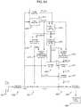
- FIG. 4shows how the noise power estimation may be embedded in a system for adaptive beamforming and noise reduction involving an adaptive target direction.
- the blocks 401, 402, 403, 404correspond to the blocks 201, 202, 203, and 204, respectively, in FIG. 2 .
- the noise analysis 409may contain a target absence detection corresponding to 309 to obtain a target absence signal T ( l,k ) with averaging in order to obtain an estimate of an M 'th order noise covariance matrix ⁇ VV ( l,k ) of the communication signals.
- a look vector estimate d ( l,k )is obtained in 414 by analysis of the noise and target covariance matrices, - this look vector analysis may in an embodiment be performed by using a single column of the matrix difference ⁇ XX ( l,k ) - ⁇ VV ( l,k ).
- the look vectoris estimated by using the eigenvector corresponding to the largest eigenvalue of said difference matrix.
- An adapted blocking matrix B ( l,k )is obtained in 415, which may be computed according to Eq. (2) based on the estimated look vector.
- the processing in blocks 406 - 408may be similar to the processing in blocks 206 - 208 of FIG 2 .
- FIG. 5shows computations for a noise reduction and beamforming method according to an embodiment of the invention.
- An embodiment according to the inventionmay comprise the steps described here explicitly or implicitly by combining multiple steps, and the particular order of the steps is not important.
- Audio signals in M channelswhere M ⁇ 2 are detected by means of a sensor array 501, and an analysis filterbank 502 processes signals into frequency dependent subbands.
- a set of N target cancelling filters 503where 1 ⁇ N ⁇ M, process the audio signals to obtain N target-cancelled signals.
- the target cancelling filtersare performed in the time domain, in others the filtering is performed in the frequency domain provided by the filterbanks.
- a target enhancing beamformer 504may process the M audio signals into a target enhanced signal.
- a target absence signal detector 505provides a signal for use of an estimator 506 providing an initial estimate of target enhancing beamformer output noise power during target absence.
- the covariance of the N -dimensional target-cancelledis obtained in one or more subbands, 507.
- the target-cancelled covariance matrixmay be regularized by adding a small value on the diagonal before matrix inversion, in order to obtain an estimated inverse target-cancelled covariance matrix which is used as coefficients of a quadratic form of order N, 508 of the target-cancelled subband signals.
- the result of the quadratic formis used as a correction scaling signal to be multiplied with the initial estimate of target enhancing beamformer output noise power to obtain a refined noise estimate of target enhancing beamformer output noise power, 509.
- the refined noise estimateforms the basis for computation of an estimate of the signal to noise ratio 510, which may in an example embodiment be used with classical methods such as Ephraim & Malah [13] (Eqs. 48 - 52) to obtain a post filter gain value in each subband, to be applied to the target enhancing beamformer 511 to obtain a post filtered enhanced target signal.
- a synthesis filterbank 512is used to obtain a time domain signal where the target signal is maintained and noise sources and residual echo signals are attenuated.
- the present disclosurerelates to the following points:
Landscapes
- Engineering & Computer Science (AREA)
- Signal Processing (AREA)
- Physics & Mathematics (AREA)
- Health & Medical Sciences (AREA)
- Acoustics & Sound (AREA)
- Computational Linguistics (AREA)
- Audiology, Speech & Language Pathology (AREA)
- Human Computer Interaction (AREA)
- Multimedia (AREA)
- Otolaryngology (AREA)
- General Health & Medical Sciences (AREA)
- Quality & Reliability (AREA)
- Circuit For Audible Band Transducer (AREA)
- Cable Transmission Systems, Equalization Of Radio And Reduction Of Echo (AREA)
Abstract
Description
- The present application relates to audio processing, in particular to speech enhancement, specifically to improving signal quality of a target speech signal in a noisy environment. The invention relates to estimation of the spectral inter-microphone correlation matrix of noise embedded in a multi-channel audio signal obtained from multiple microphones present in an acoustical environment comprising one or more target sound sources and a number of undesired noise sources.
- The invention may e.g. be used for deriving spectral signal-to-noise ratio estimates and forming spectral weights to be applied on a beamformer output signal in order to obtain an enhanced signal, where the target speech content is preserved and the noise components are significantly reduced.
- Said spectral weights may e.g. be used to further reduce a residual echo signal that has escaped from an initial stage in an echo cancellation system.
- The invention may e.g. be useful in applications such as headsets, hearing aids, active ear protection systems, mobile telephones, teleconferencing systems, karaoke systems, public address systems, mobile communication devices, hands-free communication devices, voice control systems, car audio systems, navigation systems, audio capture, video cameras, and video telephony.
- Background noise, reverberation and echo signals are typical causes of problems in systems for personal communication, and in systems involving automated recognition of voiced commands. Background noise and room reverberation can seriously decrease the sound quality and intelligibility of the desired speech signal. In a voice recognition system, background noise and reverberation increase the error rate. Furthermore, in some communication systems a speaker system delivers a known audio signal to the environment, which is picked up by a microphone array. For example, for a voice controlled TV-set it may be desired to disregard the echo of the television sound signal delivered to the loudspeakers when capturing voice commands. Similarly, in a telephone / voice communication setup, the far-end speech signal is delivered to one or more local loudspeakers, which produce an audio signal which is picked up by the local microphones as an undesirable echo. This echo should be removed before transmission of the near-end speech signal to the far-end. Similarly, a voice control system benefits from the removal of echo components.
- Traditional methods for addressing background noise include beamforming and single channel noise reduction. Beamforming allows a differentiation of sound sources by employing a spatial filter, i.e. a filter where the gain of a signal depends on the spatial direction of the sound relative to the array of microphones. Multi-microphone enhancement methods can be seen as a concatenation of a beamformer algorithm and a single channel noise reduction algorithm; therefore multi-microphone methods can perform spatial filtering in addition to the spectro-temporal filtering offered by stand-alone single-channel systems.
- The traditional method for echo cancellation is based on adaptively estimating the transfer functions from each loudspeaker signal to each of the microphone signals and subtracting an estimate of the echo from the microphone signals. However, certain components of the echo signals cannot be attenuated sufficiently by such methods, in particular in rooms with a long reverberation time. The part of the echo signal associated with late reverberation is often similar to ambient noise in that both sound fields are typically diffuse in nature. This is the primary reason that a multi-microphone spectral noise reduction system is also usable for removing the residual reverberant part of the echo signal.
- The Multi Channel Wiener filter (MWF) for speech enhancement (see e.g. [3] Chapter 3.2) is an optimal linear estimator in mean-squared error sense of a target signal, given that the microphone signal consists of the target signal with additive uncorrelated noise. The MWF can be decomposed into a concatenation of a Minimum Variance Distortionless Response (MVDR) beam former and a single-channel Wiener post-filter. While these two systems are theoretically identical, the decomposed system is advantageous in practice over a brute-force implementation of the MWF filter. Specifically, one can exploit that the spatial signal statistics, which need to be estimated to implement the MVDR beamformer, change across time at a different (often slower) rate than the signal statistics that need to be estimated to implement the post-filter.
US 2011/228951 discloses a sound processing apparatus that includes a target sound emphasizing unit configured to acquire a sound frequency component by emphasizing target sound in input sound in which the target sound and noise are included, a target sound suppressing unit configured to acquire a noise frequency component by suppressing the target sound in the input sound, a gain computing unit configured to compute a gain value to be multiplied by the sound frequency component using a gain function that provides a gain value and has a slope that are less than predetermined values when an energy ratio of the sound frequency component to the noise frequency component is less than or equal to a predetermined value, and a gain multiplier unit configured to multiply the sound frequency component by the gain value computed by the gain computing unit.- Most, if not all, post-filters rely on an estimate of the power spectral density (PSD) of the noise and undesired reverberation signal entering the post-filter. Considering a multi-microphone noise reduction system as a concatenation of a beamformer and a post-filter, it is obviously possible to estimate the noise PSD directly from the output signal of the beamformer, using well-known single-channel noise tracking algorithms (see e.g. [4] Section II, Eq. (1)-(3)). However, generally speaking, better performance can be obtained by taking advantage of having multiple microphone signals available when estimating the PSD of the noise entering the post-filter.
- The idea of using multiple microphone signals for estimating the PSD of the noise that enters the post filter is not new. In [10] (
Fig. 1 ), Zelinski used multiple microphone signals to estimate the noise PSD observed at the microphones under the assumption that the noise sequences were uncorrelated between microphones, i.e., the inter-microphone noise covariance matrix was diagonal. McCowan [11] (Fig. 1 ) and Lefkimmiatis [12] (Fig. 1 ) replaced this often unrealistic model with a diffuse (homogenous, isotropic) model of the noise field. More recently, Wolff [9] (Fig. 1 ) considered the beamformer in a generalized sidelobe canceller (GSC) structure, and used the output of a blocking matrix, combined with a voice activity detection (VAD) algorithm, to compute an estimate of the PSD of the noise entering the post-filter. - Herein we disclose a method and corresponding apparatus which estimate the time-varying and frequency-dependent inter-microphone noise covariance matrix, which unlike previously published methods and apparatus are optimal in a maximum likelihood sense.
- In the described embodiments, the noise covariance matrix may be used for noise reduction, speech enhancement, and attenuation of residual echo signals, or for improving the recognition rate in a voice control system. It is an advantage of the invention that the noise is estimated accurately, because this may lead to an improved sound quality in the enhanced audio signal, or may improve the recognition rate of an automated voice control system.
- In an embodiment, the spectral correlation matrix may be used for estimation of the noise level at the output of a beamformer that operates on a multi-channel audio signal such as signals obtained from an array of two or more microphones. This noise estimate may be used for estimation of a signal-to-noise ratio at the beamformer output, which may be used for calculation of a frequency dependent gain weight to be applied in a post-filtering of the beamformer output. A further embodiment is described where the estimated noise level at the output of a beamformer that operates on the multichannel audio signal is used along with the beamformer output signal for automated voice command recognition.
- In the following section, a noise power estimator is derived. Let the noisy signal impinging on them'th microphone be given by

- Each microphone signal may be passed through a discrete Fourier Transform (DFT) filterbank, leading to complex DFT coefficients


- We employ the standard assumption that DFT coefficients are independent across frame and frequency index, which allows us to process each DFT coefficient independently. Thus, without loss of generality, for a given frequency indexk, we can collect the DFT coefficients of framel for each microphone in a vector


- Similar equations describe the target vector


- We model the target signal as a point source impinging on the array. Letd(l,k) = [d1(l,k)···dM(l,k)]T denote the (complex-valued) propagation vector whose elementsdm represent the respective acoustic transfer function from the source to them'th microphone, evaluated at frequency indexk. Then,X(l,k) may be written as,X(l,k) =x(l,k)d(l,k), wherex(l,k) is the clean target DFT coefficient with frame indexl at the frequency index in question.
- Now, the correlation matrix ΦYY(l,k) of the noisy signalY(l,k) is defined as the averageE[Y(l,k)YH(l,k)] where the superscriptH denotes Hermitian transposition (conjugate transposed). By assuming independence of target and noise, ΦYY(l,k) can be written as the sum of the noise and target covariance matrices, ΦXX(l,k) and ΦVV(l,k), respectively. That is,

- Finally, let us assume the following model for the development of the noise covariance matrix across time,

- Thus, this model can be seen as a relaxation of the methodology known from early single-channel noise reduction systems, where the noise power estimated in the most recent noise-only region is assumed to remain constant across time when speech is present.
- The goal in this section is to derive an estimate of the noise covariance matrix ΦVV(l,k) =c2(l,k)ΦVV(l0,k),l >l0, that is, when speech is present. The general idea is to do this based on the output of a set of linearly independent target cancelling beamformers, sometimes referred to as a blocking matrix in GSC terminology [5] (
Fig. 4 ), see also [6] (Chapter 5.9 and the references therein). - Consider any full-rank matrix


- Obviously, many such matrices exist. Assume thatd(l,k) is known and normalized to unit length, and letH(l,k) =IM -d(l,k)dH(l,k), whereIM is theM-dimensional identity matrix. Then, it can be verified that one such matrixB(l,k) is given by the firstN columns of matrixH, that is

- Each column of matrixB can be considered a target-cancelling beamformer, because when applied to the noisy input vectorY(l,k), the output


- From the above equation the covariance matrix ofZ(l,k) is given by

- Inserting Eq. 1 in Eq. 4 we find

- For a complex filterbank, it follows from the Gaussian assumption that vectorZ(l,k) obeys a zero-mean (complex, circular symmetric) Gaussian distribution, that is,

- Thus the likelihood functioncan be written as


- Maximizingwith respect to the unknown scaling factorc2(l,k) leads to the maximum likelihood estimate


- Note that Equation 6 devices two different ways of estimating the scaling factor

- We further note that


- Finally, let


- In an equivalent manner, an estimate of the power of the noise in the beamformer output may be given by

- In an embodiment, this noise power estimate may be used to derive a post-filter gain value. By comparing the magnitude of the beamformer output signal to the noise power, a signal-to-noise ratio may be derived, which may be used for computing a gain value. In other embodiments where voice recognition is employed on the beamformer output signal, the voice recognition may benefit from being based on both a beamformed signal and a noise PSD estimate.
- Thus, a method for audio signal processing by a combination of beamforming and adaptive post-filtering of acoustic signals received from a microphone array may comprise some or all of the steps of:
receivingM communication signals in frequency subbands whereM is at least two; - in each subband processing the respectiveM subband communication signals with a blocking matrix(203,303,403) ofM rows andN linearly independent columns, whereN>=1 andN<M, to obtainN target cancelled signals;
- in each subband, processing the respectiveM subband communication signals and theN target cancelled signals with a set of beamformer coefficients(204,304,404) to obtain a beamformer output signal;
- processing theM communication signals with a target absence detector(309) to obtain a target absence signal in each subband;
- using the target absence signal to obtain an inverse target-cancelled covariance matrix of orderN(310,410) in each subband;
- processing theN target-cancelled signals in each subband with the inverse target-cancelled covariance matrix in a quadratic form(312, 412) to yield a real-valued noise correction factor in each subband;
- using the target absence signal to obtain an initial estimate(311, 411) of the noise power in the beamformer output signal averaged over recent frames with target absence in each subband;
- multiplying the initial noise estimate with the noise correction factor to obtain a refined estimate(417) of the power of the beamformer output noise signal component in each subband;
- processing the refined estimate of the power of the beamformer output noise signal component with the magnitude of the beamformer output to obtain a postfilter gain value in each subband;
- processing the beamformer output signal with the postfilter gain value(206,306,406) to obtain a postfilter output signal in each subband;
- processing the postfilter output subband signals through a synthesis filterbank(207,307,407) to obtain an enhanced beamformed output signal where the target signal is enhanced by attenuation of noise signal components.
- It is an advantage that the postfilter gain value is derived from an accurate estimate of the power of the noise component of the beamformer output. This is achieved in that the noise power is derived from a combination of N target-cancelled signals each of which are obtained from independent spatial filters (i.e. a blocking matrix) that cancel the desired target signal, and are therefore affected very little by it. This allows estimation of noise levels even in the presence of a target signal.
- By use of a quadratic form with matrix coefficients that are derived as the inverse correlation matrix of the N blocking matrix signals the estimate becomes optimal in a maximum likelihood sense. Previous methods for estimation of beamformer output noise using spatial filters [1] (
Fig. 2 , block 15),[2] (Fig. 2 ), [7] (Fig 2 ), [10] (Fig. 1 ), [11] (Fig. 1 ), [12] (Fig. 1 ) have not had this property and are therefore less accurate. - A traditional method for echo cancellation comprises an adaptive estimate of the transfer functions from each loudspeaker signal to each of the microphone signals, and to subtract the predicted loudspeaker signal component from each of the detected microphone signals. Because certain components of the echo signals may not in practice be attenuated well enough, in particular in connection with long room impulse responses, it is an advantage of the disclosed method that the residual echo signal associated with the late reverberation is estimated as ambient noise and in an embodiment is subsequently attenuated by an adaptive post filter.
- In other embodiments it is an advantage that a late reverberation signal and noise is estimated accurately because it may allow an increased recognition rate of a voice control system that is being passed an adaptively beamformed signal as well as an estimate of the noise PSD in said signal.
- In an embodiment, the target enhancing beamformer is an MVDR beamformer [3] (Chapter 2.3 Eq. 2.25) implemented by means of a GSC structure, see e.g. [3] (Chapter 5.2,
Fig. 5.1 ). The proposed method is advantageous in that it shares many of the same computational steps with the MVDR beamformer implemented in the GSC form. This can be realized by considering an MVDR beamformer which may be implemented by the equationyMVDR(l,k) =


- It should be stressed that the operatorE[·] in this disclosure is used in the meaning "average", which is meant to be interpreted either as a statistical expectation, or as an empirical average over a batch of samples, or as a lowpass filter of recent samples. A common averaging formula is to use a first order IIR low pass filter corresponding to thez-transformH(z) =λ/(1 - (1 -λ)z-1), whereλ is a parameter satisfying 0 ≤λ(1) ≤ 1 defining the time constantτ(l) of the averaging process where the relationship between the time constantτ(l) andλ(l) may be computed as


- In an embodiment the coefficientλ(l,k) is made time variant in order to be able to control over which time frame instances, or with what weighting of individual time frame instances, the average should be computed. Preferably, the averaging is performed over frames with target absence, as indicated by a target absence signalT(l,k) in each subband. In an embodiment, the signalT(l,k) attains a
value 1 when target is absent and a predetermined value ofε close or equal to 0, otherwise, and the coefficientλ(l,k) is made to depend on target absence by the relationλ(l,k) =T(l,k)λ0(k), whereλ0(k) reflects a predetermined averaging time constant for each subband. In a further embodiment the signalT(l,k) is derived from the output of a VAD (voice activity detector). - Since both the MVDR coefficient calculation for target enhancing beamformer coefficients and the noise estimation method benefit from averaging over frames dominated by undesired signals, such as noise signals, microphone noise, and residual echo signals, theN'th order inverse matrix

- In some communication situations the acoustical direction of incidence of the target signal is not predetermined. In an embodiment it is an advantage in such acoustical setups to adaptively estimate the blocking matrix. In a further embodiment this may be done by adaptively estimating a look vectord(l,k) in each subband by analysis of a covariance matrix estimated during frames with target signal presence as indicated by a target presence signal, derived, e.g., from a voice activity detector. In an embodiment said analysis is performed by means of a generalized eigenvector analysis of theM'th order covariance matrix ΦVV(l0,k) of microphone signals estimated during recent frames of target absence and theM'th order covariance matrix of microphone signals estimated during recent frames of target presence ΦYY(lP,k), wherelP may represent latest frame index with target presence. Said analysis may be performed by deriving the eigenvector corresponding to the largest eigenvalue of the generalized eigenvalue problem ΦYY(lP,k)v =λΦVV(l0,k)v, where


- As used herein, the singular forms "a," "an," and "the" are intended to include the plural forms as well (i.e. to have the meaning "at least one"), unless expressly stated otherwise. It will be further understood that the terms "includes," "comprises," "including," and/or "comprising," when used in this specification, specify the presence of stated features, integers, steps, operations, elements, and/or components, but do not preclude the presence or addition of one or more other features, integers, steps, operations, elements, components, and/or groups thereof. It will also be understood that when an element is referred to as being "connected" or "coupled" to another element, it can be directly connected or coupled to the other element or intervening elements may be present, unless expressly stated otherwise. Furthermore, "connected" or "coupled" as used herein may include wirelessly connected or coupled. As used herein, the term "and/or" includes any and all combinations of one or more of the associated listed items. The steps of any method disclosed herein do not have to be performed in the exact order disclosed, unless expressly stated otherwise.
- The invention will be explained more fully below in connection with a preferred embodiment and with reference to the drawings in which:
FIG. 1 shows a user in a personal communication or voice control scenario, with an echo cancellation and noise reduction system in an embodiment according to the invention.FIG. 2 shows a combined echo cancellation system, beamformer and noise reduction and residual echo reduction system based on noise and residual echo power estimation in an embodiment according to the invention.FIG. 3 shows a beamformer and noise reduction system, with a blocking matrix, a target absence detector, and a quadratic form for noise estimation refinement based on the inverse target-cancelled covariance matrix, in an embodiment according to the invention.FIG. 4 shows a beamformer and noise reduction system with adaptive target direction and noise power estimation in an embodiment according to the invention.FIG. 5 shows computational steps in a beamformer and noise reduction system in an embodiment according to the invention.- The figures are schematic and simplified for clarity, and they just show details which are essential to the understanding of the disclosure, while other details are left out. Throughout, the same reference numerals are used for identical or corresponding parts.
- Further scope of applicability of the present disclosure will become apparent from the detailed description given hereinafter. However, it should be understood that the detailed description and specific examples, while indicating preferred embodiments of the disclosure, are given by way of illustration only. Other embodiments may become apparent to those skilled in the art from the following detailed description.
- In the following description, reference is made to the accompanying figures, which illustrate how the invention may be practiced.
FIG. 1 shows a schematic view of a user in a communication situation, which may represent a hands-free telephone situation in e.g. a car, a teleconference, or a voice control situation, where a device is performing residual echo and noise reduction. Auser 105 is situated withambient noise sources 102 where one ormore loudspeakers 103 reproduce an acoustical signal from e.g. a far-end speaker 104. The loudspeaker(s) could also be reproducing a signal from other sound sources, such as radio, music source, sound tracks, karaoke system, etc. The user may produce a target speech signal which it is the aim of the device to detect with high quality. An array ofM transducers 101 detect an acoustical mixture signal which may be composed of a superposition of the target speech signal, echo signals from the loudspeakers, ambient noise, and transducer noise. The microphone array signals and the loudspeaker signals are passed to an initialecho cancelling system 106, which adaptively estimates the transfer function from one or more of the loudspeakers to one or more of the microphones, and subtracts a signal generated by filtering one or more of the loudspeaker signals according to one or more of the estimated transfer functions to obtainM initial echo cancelled communication signals. These communication signals are passed to abeamformer 107 which implements a spatial filter to enhance the target speech signal and attenuate noise and residual echo signals, and may in some embodiments also be processed by apost filter 107 to further reduce noise and residual echo signals by means of a time-frequency dependent gain function derived from a time-frequency dependent estimate of the signal-to-disturbance ratio, which is derived from a time-frequency dependent noise estimate. In a voice control situation an enhanced signal, which may or may not have been post-filtered, is passed to asubsequent system 108 for speech recognition. In a teleconference system, an enhanced signal is transmitted back to the far end. In other embodiments a representation of the time-frequency dependent noise power estimate is passed to the subsequent voice recognition system in addition to an enhanced signal.FIG. 2 shows how the disclosednoise power estimator 205 may be embedded in a communication system with echo cancelling, beamforming, and noise reduction. A loudspeaker signal in one or more audio channels is available in digital form from anaudio signal source 211 and is reproduced as an acoustical signal by one or more loudspeakers. A set of echo filters210 adapted to match the acoustical echo transfer functions, filter the loudspeaker signals to obtain an echo signal estimate for each of theM microphones,M > 1. The echo signal estimate is subtracted from the microphone signals to obtainM communication signalsym(n),m = 1..M wheren is a discrete sample time index. In an embodiment an analysis filterbank (not shown) processes each loudspeaker signal and the acoustical echo transfer functions are estimated in one or more subbands and the subsequent subtraction of the estimated echo signal at each microphone signal is performed in the subband domain. Afilterbank 202 produces a time-frequency representation of each communication signal, which in an embodiment may be performed as a short time Fourier transform (STFT) to obtain coefficients

beamformer 204 processes theM communication signals to obtain an enhanced beamformed signal by means of a set of beamformer weightsw(l,k) so thatYw(l,k) =wH(l,k)Y(l,k). The beamformer may in some embodiments have predetermined weights. In other embodiments the beamformer may be adaptive. A common method is a Generalized Sidelobe Canceller (GSC) structure where the blocking matrix signalZ(l,k) is adaptively filtered with coefficientsq(l,k) and subtracted from a predetermined reference beamformerw0(k), to minimize the beamformer output, e.g.w(l,k) =w0(k)- B(l,k)q(l,k). Thenoise power estimator 205 provides an estimateφ̂VV(l,k) of the power of the noise component of the enhanced beamformed signal, and is detailed further inFIG. 3 . The noise power estimate is used by thepost filter 206 to yield a time-frequency dependent gaing(l,k) which is applied to the enhanced beamformed signal. The gain may be derived by means of a gain function, e.g. as function of the estimated signal-to-noise-ratio (SNR) valueξ(l,k), asg(l,k) =G(ξ(l,k)), which in some embodiments can be a bounded Wiener filter, i.e.,


synthesis filterbank 207 which produces an enhanced time domain signal where the target signal is preserved and noise and echo signals are attenuated. The synthesis filterbank may apply an overlap-sum scheme so that an enhanced output signalx̃(n) is obtained, according to
FIG. 3 shows further details of anoise power estimator 205 according to an embodiment of the invention. In the diagram, blocks301 -308 correspond to blocks201 -208 inFIG. 2 , and block309 -312 represent details of thenoise power estimator 205. Atarget absence detector 309 processes the subband communication signalsY(l,k) to obtain a target absence indicator signalT(l,k), which in an embodiment may be a binary indicator derived from a comparison of a short term averaged power 〈|Y(l,k)|2〉 to a noise floor power estimator, such as R. Martin [4] (Section II - III), operating on the reference microphone signal in each subband, so that target absence is assumed when the ratio of the short term averaged power to the noise floor power estimate does not exceed a predetermined threshold value, for example 8 dB. The inverse target-cancelled covariance matrix
value 1 when target is absent and 0 otherwise, so by lettingλ(l,k) =T(l,k)λ0, the covariance may be computed as an average over recent frames with target absence. The predetermined parameterλ0 may in an example embodiment be set to correspond to a predetermined time constant of 0.1 seconds. An initial noise power estimate φVV0(l,k) is computed in311. In this computation it is important to use the same target absence signal and the same averaging process as used in310, which in an embodiment corresponds to the averaging process φVV0(l,k) = (Yw(l,k)YwH(l,k) - φVV0(l - 1,k))λ(l,k) + φVV0(l - 1,k), and using the same signalλ(l,k). A quadratic form is used in312 to compute the correction factor


FIG 2 .FIG. 4 shows how the noise power estimation may be embedded in a system for adaptive beamforming and noise reduction involving an adaptive target direction. Theblocks blocks FIG. 2 . Thenoise analysis 409 may contain a target absence detection corresponding to309 to obtain a target absence signalT(l,k) with averaging in order to obtain an estimate of anM'th order noise covariance matrix ΦVV(l,k) of the communication signals. In an embodiment, the averaging is performed as a recursive filter ΦVV(l,k) = (Y(l,k)YH(l,k) - ΦVV(l -1,k))λ(l,k) + ΦVV(l - 1,k) whereλ(l,k) =T(l,k)λ0, andλ0 is a predetermined parameter which may in an example embodiment be set to correspond to a time constant of 0.1 seconds. A target covariance matrix is obtained from thetarget analysis 413, and may in an embodiment comprise target presence detection to obtain a target presence signalS(l,k) which may be in form of a VAD (voice activity detector), such thatS(l,k) = 1 if target is present and 0 otherwise, and may in an embodiment be used with a recursive averaging process ΦXX(l,k) = (Y(l,k)YH(l,k)- ΦXX(l - 1,k))S(l,k)λ0 + ΦXX(l - 1,k) to obtain an average of target dominated frames. A look vector estimated(l,k) is obtained in414 by analysis of the noise and target covariance matrices, - this look vector analysis may in an embodiment be performed by using a single column of the matrix difference ΦXX(l,k) - ΦVV(l,k). In a further embodiment the look vector is estimated by using the eigenvector corresponding to the largest eigenvalue of said difference matrix. An adapted blocking matrixB(l,k) is obtained in415, which may be computed according to Eq. (2) based on the estimated look vector. From the noise covariance estimate and the look vector, an embodiment may derive a set ofbeamformer coefficients 416, which may be a set of MVDR coefficients according to
beamformer noise estimate 411 may be derived as φVV0(l,k) =wH(l,k)ΦVV(l,k)w(l,k). Likewise, an inverse target-cancelled covariance matrix may be computed in410 as


FIG 2 .FIG. 5 shows computations for a noise reduction and beamforming method according to an embodiment of the invention. An embodiment according to the invention may comprise the steps described here explicitly or implicitly by combining multiple steps, and the particular order of the steps is not important. Audio signals inM channels, whereM ≥ 2 are detected by means of asensor array 501, and ananalysis filterbank 502 processes signals into frequency dependent subbands. A set ofNtarget cancelling filters 503 , where 1 ≤N < M, process the audio signals to obtain N target-cancelled signals. In some embodiments the target cancelling filters are performed in the time domain, in others the filtering is performed in the frequency domain provided by the filterbanks. Atarget enhancing beamformer 504 may process theM audio signals into a target enhanced signal. A targetabsence signal detector 505 provides a signal for use of anestimator 506 providing an initial estimate of target enhancing beamformer output noise power during target absence. Using the same target absence signal, the covariance of theN-dimensional target-cancelled is obtained in one or more subbands,507. In some embodiments the target-cancelled covariance matrix may be regularized by adding a small value on the diagonal before matrix inversion, in order to obtain an estimated inverse target-cancelled covariance matrix which is used as coefficients of a quadratic form of orderN,508 of the target-cancelled subband signals. The result of the quadratic form is used as a correction scaling signal to be multiplied with the initial estimate of target enhancing beamformer output noise power to obtain a refined noise estimate of target enhancing beamformer output noise power,509. The refined noise estimate forms the basis for computation of an estimate of the signal tonoise ratio 510, which may in an example embodiment be used with classical methods such as Ephraim & Malah [13] (Eqs. 48 - 52) to obtain a post filter gain value in each subband, to be applied to thetarget enhancing beamformer 511 to obtain a post filtered enhanced target signal. Asynthesis filterbank 512 is used to obtain a time domain signal where the target signal is maintained and noise sources and residual echo signals are attenuated.- The invention is defined by the features of the independent claims. Preferred embodiments are defined in the dependent claims. Any reference numerals in the claims are intended to be non-limiting for their scope.
- Some preferred embodiments have been shown in the foregoing, but it should be stressed that the invention is not limited to these, but may be embodied in other ways within the subject-matter defined in the following claims. For example, in a hearing aid, further processing steps may be required, for example steps for hearing loss compensation.
- [1]
EP 2 026 597 B1 , Noise reduction by combined beamforming and post-filtering. - [2]
US patent 8,204,263 B2 , Method of estimating a weighting function of audio signals in a hearing aid. - [3]M. Brandstein and D. Ward, "Microphone Arrays", Springer 2001.
- [4]R. Martin, "Noise Power Spectral Density Estimation Based on Optimal Smoothing and Minimum Statistics", IEEE Trans. on Speech and Audio Processing, vol. 9, no. 5, 2001.
- [5] L. J. Griffiths and C. W. Jim, "An Alternative Approach to Linearly Constrained Adaptive Beamforming," IEEE Trans. Antennas Propagat., vol. 30, no. 1, pp. 27-34, January 1982.
- [6]S. Haykin, Adaptive Filter Theory, Prentice Hall, Third edition, 1996
- [7] K. U. Simmer, J. Bitzer, and C. Marro, "Post-Filtering Techniques," in Microphone Arrays - Signal Processing Techniques and Applications, M. Brandstein and D. Ward, Eds. 2001, Springer Verlag.
- [8] E. Warsitz, "Blind Acoustic Beamforming Based on Generalized Eigenvalue Decomposition", IEEE Trans. Audio Speech and Language Processing, Vol. 15, no 5, 2007.
- [9]T. Wolff and M. Buck, "Spatial maximum a posteriori post-filtering for arbitrary beamforming," in Handsfree Speech Communication and Microphone Arrays (HSCMA), 2008.
- [10]R. Zelinski, "A Microphone Array With Adaptive Post-Filtering for Noise Reduction in Reverberant Rooms," in Proc. IEEE International Conference on Acoustics, Speech and Signal Processing, 1988, vol. 5, pp. 2578-2581.
- [11]I. A. McCowan and H. Bourlard, "Microphone Array Post-Filter Based on Noise Field Coherence," IEEE Trans. Speech and Audio Processing, vol. 11, no. 6, pp. 709-716, 2003.
- [12]S. Lefkimmiatis and P. Maragos, "Optimum post-filter estimation for noise reduction in multichannel speech processing," in Proc. 14th European Signal Processing Conference, 2006.
- [13]Y. Ephraim and D. Malah, "Speech enhancement using a minimum-mean square error short-time spectral amplitude estimator," Acoustics, Speech and Signal Processing, IEEE Transactions on , vol.32, no.6, pp. 1109- 1121, Dec 1984.
- The present disclosure relates to the following points:
- 1. A method for audio signal processing, the method comprising:
- in one or more frequency subbands, receivingM communication signals (Ym(l,k)) in time frames and comprising a target signal (Xm(l,k)) and a noise signal (Vm(l,k)), whereM≥2;
- in each subband, processing theM subband communication signals (Ym(l,k)) with a set of beamformer coefficients (w(l,k)204, 304, 404) to obtain a beamformer output signal (Yw(l,k));
- in each subband, processing theM subband communication signals (Ym(l,k)) inN linearly independent target-cancelling beamformers (B(l,k),203, 303, 403), where1≤N<M, to obtainN target-cancelled signals (Z(l,k)) wherein the target signal (Xm(l,k)) is suppressed relative to the noise signal (Vm(l,k));
- processing the communication signals (Ym(l,k)) with a target absence detector(309) to obtain a target absence signal (T(l,k));
- in each subband, estimating a covariance matrix (ΦZZ(l,k)) of orderN of the target-cancelled signals (Z(l,k)) as an average, where individual time frames are weighted as a function of the target absence signal (T(l,k));
- in each subband, estimating an inverse target-cancelled covariance matrix

- in each subband, determining a real-valued scaling factor


- in each subband, determining an initial estimate (φVV0(l,k)311, 411) of the noise power in the beamformer output signal (Yw(l,k)) as an average, where individual time frames are weighted using said function of the target absence signal (T(l,k));
- in each subband, multiplying the initial noise estimate (φVV0(l,k)) with the scaling factor

- 2. A method according to
claim 1 where- determining the initial estimate (φVV0(l,k)311, 411) of the noise power in the beamformer output signal (Yw(l,k)) comprises determining the initial estimate (φVV0(l,k)311, 411) of the noise power in the beamformer output signal (Yw(l,k)) in dependence of the set of beamformer coefficients (w(l,k)204, 304, 404).
- 3. A method according to
claim 1 or 2 where- in one or more subbands, the beamformer output signal (Yw(l,k),204,304,404) is generated using at least one adaptive filter derived from the inverse target-cancelled covariance matrix

- in one or more subbands, the beamformer output signal (Yw(l,k),204,304,404) is generated using at least one adaptive filter derived from the inverse target-cancelled covariance matrix
- 4. A method according to any of claims 1-3 where
- in one or more subbands, theN linearly independent target cancelling beamformers (B(l,k),203,303,403) are computed adaptively(415) from analysis of theM communication signals.
- 5. A method according to claim 4 where
- in one or more subbands, theN linearly independent target cancelling beamformers (B(l,k),203,303,403) are determined adaptively from a look vector (d(l,k),414) derived from an analysis(413) of anM'th order mixture covariance matrix estimated during recent frames of target presence, and anM'th order noise covariance matrix(409) of communication signals estimated during recent frames of target absence.
- 6. A method according to claim 5 where
- in one or more subbands, said analysis comprises an eigenvector analysis of a difference between said mixture covariance matrix and said noise covariance matrix and selecting the eigenvector associated with the largest eigenvalue as the look vector (d(l,k)).
- 7. A method according to claim 5 where
- in one or more subbands, said analysis comprises a generalized eigenvector analysis of the inverse of said noise covariance estimate multiplied with said mixture covariance matrix and using the eigenvector associated with the largest eigenvalue to obtain the look vector (d(l,k)).
- 8. A method according to any of the claims 1-7 where
- in each subband, the inverse target-cancelled covariance matrix

- estimating a target-cancelled covariance matrix (ΦZZ(l,k)) as an average of said outer product matrix, where individual time frames are weighted as a function of the target absence signal (T(l,k))
- inverting the target-cancelled covariance matrix (ΦZZ(l,k)) to obtain the inverse target-cancelled covariance matrix

- in each subband, the inverse target-cancelled covariance matrix
- 9. A method according to any of the claims 1 - 7 where said inverse target-cancelled covariance matrix

- in each subband, processing theM communication signals by an outer product to obtain an outer product signal matrix of orderM;
- estimating a noise covariance matrix (ΦVV(l,k)) of orderM as an average of said outer product matrix, where individual time frames are weighted as a function of the target absence signal (T(l,k))
- in each subband, processing the noise covariance matrix (ΦVV(l,k)) with the blocking matrix (B(l,k)) to obtain a target-cancelled covariance matrix (ΦZZ(l,k)) of orderN;
- in each subband, inverting the target-cancelled covariance matrix (ΦZZ(l,k)) to obtain the inverse target-cancelled covariance matrix

- 10. A method according to any preceding claim, further comprising
- receiving an audio signal by means of a microphone array(101,201,301,401) comprisingM microphones, to obtainM microphone signals (ym(n)) each comprising a target signal (xm(n)) and a noise signal (vm(n));
- passing theM microphone signals (ym(n)) through an analysis filterbank(202,302,402) to obtain theM communication signals (Ym(l,k)) in one or more frequency subbands;
- in each subband, determining a post-filter gain value in dependence on the refined estimate (φVV(l,k)) of the noise power in the beamformer output signal (Yw(l,k)) and the beamformer output signal (Yw(l,k));
- in each subband, processing the beamformer output signal (Yw(l,k)) with the postfilter gain value(206,306,406) to obtain a postfilter output signal;
- combining the postfilter output signals of the subbands in a synthesis filterbank(207,307,407) to obtain an enhanced beamformed output signal.
- 11. A method according to any preceding claim, further comprising
- receivingL loudspeaker signals (ui(n)) fromL respective loudspeakers(209) whereL≥1,
- receiving an audio signal by means of a microphone array(101,201,301,401) comprisingM microphones, to obtainM echo-contaminated microphone signals (am(n)) each comprising a target signal (xm(n)) and a noise signal (vm(n));
- adaptively estimating filter weights(210) for filtering each of theL loudspeaker signals (ui(n)) to approximate each of theM echo-contaminated microphone signals (am(n));
- subtracting each of theL filtered speaker signals from each of theM echo-contaminated microphone signals (am(n)) to obtainM echo-cancelled microphone signals (ym(n)).
- in each subband, determining a post-filter gain value in dependence on the refined estimate (φVV(l,k)) of the noise power in the beamformer output signal (Yw(l,k)) and the beamformer output signal (Yw(l,k));
- in each subband, processing the beamformer output signal (Yw(l,k)) with the postfilter gain value(206,306,406) to obtain a postfilter output signal;
- combining the postfilter output signals of the subbands in a synthesis filterbank(207,307,407) to obtain an enhanced beamformed output signal.
- 12. A method according to any preceding claim where the enhanced beamformed output signal is used as input to a voice control system.
- 13. A method according to any of the claims 1-11 where the beamformer output signal and the refined estimate of the power of the beamformer output noise signal component are used as input to a voice control system.
- 14. An apparatus adapted to execute a method according to any of the preceding claims.
- 15. A hearing aid adapted to execute a method according to any of the claims 1-12.


Claims (15)
- A method for audio signal processing, the method comprising:- in one or more frequency subbands, receivingM communication signals (Ym(l,k)) in time frames and comprising a target signal (Xm(l,k)) and a noise signal (Vm(l,k)), whereM≥2;- in each subband, processing theM subband communication signals (Ym(l,k)) with a set of beamformer coefficients (w(l,k)204, 304, 404) to obtain a beamformer output signal (Yw(l,k));- in each subband, processing theM subband communication signals (Ym(l,k)) inN linearly independent target-cancelling beamformers (B(l,k),203, 303, 403), where1≤N<M, to obtainN target-cancelled signals (Z(l,k)) wherein the target signal (Xm(l,k)) is suppressed relative to the noise signal (Vm(l,k));- processing the communication signals (Ym(l,k)) with a target absence detector(309) to obtain a target absence signal (T(l,k));- in each subband, estimating an inverse target-cancelled covariance matrix
 - in each subband, determining a real-valued scaling factor (
 - in each subband, determining an initial estimate (φVV0(l,k)311, 411) of the noise power in the beamformer output signal (Yw(l,k)) as an average, where individual time frames are weighted using said function of the target absence signal (T(l,k));- in each subband, multiplying the initial noise estimate (φVV0(l,k)) with the scaling factor
 - in one or more subbands, theN linearly independent target cancelling beamformers (B(l,k),203,303,403) are computed adaptively(415) from analysis of theM communication signals.
 - The method according to claim 1, further comprising a step of:- in each subband, estimating a covariance matrix (ΦZZ(l,k)) of orderN of the target-cancelled signals (Z(l,k)) as an average, where individual time frames are weighted as a function of the target absence signal (T(l,k));
- A method according to claim 1 or 2 where- determining the initial estimate (φVV0(l,k)311, 411) of the noise power in the beamformer output signal (Yw(l,k)) comprises determining the initial estimate (φVV0(l,k)311, 411) of the noise power in the beamformer output signal (Yw(l,k)) in dependence of the set of beamformer coefficients (w(l,k)204, 304, 404).
- A method according to any of claims 1 to 3, where- in one or more subbands, the beamformer output signal (Yw(l,k),204,304,404) is generated using at least one adaptive filter derived from the inverse target-cancelled covariance matrix

- A method according to claim 1 where- in one or more subbands, theN linearly independent target cancelling beamformers (B(l,k),203,303,403) are determined adaptively from a look vector (d(l,k),414) derived from an analysis(413) of anM'th order mixture covariance matrix estimated during recent frames of target presence, and anM'th order noise covariance matrix(409) of communication signals estimated during recent frames of target absence.
- A method according to claim 5 where- in one or more subbands, said analysis comprises an eigenvector analysis of a difference between said mixture covariance matrix and said noise covariance matrix and selecting the eigenvector associated with the largest eigenvalue as the look vector (d(l,k)).
- A method according to claim 5 where- in one or more subbands, said analysis comprises a generalized eigenvector analysis of the inverse of said noise covariance estimate multiplied with said mixture covariance matrix and using the eigenvector associated with the largest eigenvalue to obtain the look vector (d(l,k)).
- A method according to any of the claims 1-7 where- in each subband, the inverse target-cancelled covariance matrix
 - estimating a target-cancelled covariance matrix (ΦZZ(l,k)) as an average of said outer product matrix, where individual time frames are weighted as a function of the target absence signal (T(l,k))- inverting the target-cancelled covariance matrix (ΦZZ(l,k)) to obtain the inverse target-cancelled covariance matrix
- A method according to any of the claims 1 - 7 where said inverse target-cancelled covariance matrix
 - in each subband, processing theM communication signals by an outer product to obtain an outer product signal matrix of orderM;- estimating a noise covariance matrix (ΦVV(l,k)) of orderM as an average of said outer product matrix, where individual time frames are weighted as a function of the target absence signal (T(l,k))- in each subband, processing the noise covariance matrix (ΦVV(l,k)) with the blocking matrix (B(l,k)) to obtain a target-cancelled covariance matrix (ΦZZ(l,k)) of orderN;- in each subband, inverting the target-cancelled covariance matrix (ΦZZ(l,k)) to obtain the inverse target-cancelled covariance matrix
- A method according to any preceding claim, further comprising- receiving an audio signal by means of a microphone array(101,201,301,401) comprisingM microphones, to obtainM microphone signals (ym(n)) each comprising a target signal (xm(n)) and a noise signal (vm(n));- passing theM microphone signals (ym(n)) through an analysis filterbank(202,302,402) to obtain theM communication signals (Ym(l,k)) in one or more frequency subbands;- in each subband, determining a post-filter gain value in dependence on the refined estimate (φVV(l,k)) of the noise power in the beamformer output signal (Yw(l,k)) and the beamformer output signal (Yw(l,k));- in each subband, processing the beamformer output signal (Yw(l,k)) with the postfilter gain value(206,306,406) to obtain a postfilter output signal;- combining the postfilter output signals of the subbands in a synthesis filterbank(207,307,407) to obtain an enhanced beamformed output signal.
- A method according to any preceding claim, further comprising- receivingL loudspeaker signals (ui(n)) fromL respective loudspeakers(209) whereL≥1,- receiving an audio signal by means of a microphone array(101,201,301,401) comprisingM microphones, to obtainM echo-contaminated microphone signals (am(n)) each comprising a target signal (xm(n)) and a noise signal (vm(n));- adaptively estimating filter weights(210) for filtering each of theL loudspeaker signals (ui(n)) to approximate each of theM echo-contaminated microphone signals (am(n));- subtracting each of theL filtered speaker signals from each of theM echo-contaminated microphone signals (am(n)) to obtainM echo-cancelled microphone signals (ym(n)).- in each subband, determining a post-filter gain value in dependence on the refined estimate (φVV(l,k)) of the noise power in the beamformer output signal (Yw(l,k)) and the beamformer output signal (Yw(l,k));- in each subband, processing the beamformer output signal (Yw(l,k)) with the postfilter gain value(206,306,406) to obtain a postfilter output signal;- combining the postfilter output signals of the subbands in a synthesis filterbank(207,307,407) to obtain an enhanced beamformed output signal.
- A method according to any preceding claim where the enhanced beamformed output signal is used as input to a voice control system.
- A method according to any of the claims 1-11 where the beamformer output signal and the refined estimate of the power of the beamformer output noise signal component are used as input to a voice control system.
- A hearing aid adapted to execute a method according to any of the claims 1-12.
- A binaural hearing aid system comprising two hearing aids each adapted to execute a method according to any of the claims 1-12.


Priority Applications (1)
| Application Number | Priority Date | Filing Date | Title |
|---|---|---|---|
| EP18200053.9AEP3462452A1 (en) | 2012-08-24 | 2012-08-24 | Noise estimation for use with noise reduction and echo cancellation in personal communication |
Applications Claiming Priority (3)
| Application Number | Priority Date | Filing Date | Title |
|---|---|---|---|
| EP16193246.2AEP3190587B1 (en) | 2012-08-24 | 2012-08-24 | Noise estimation for use with noise reduction and echo cancellation in personal communication |
| EP12181723.3AEP2701145B1 (en) | 2012-08-24 | 2012-08-24 | Noise estimation for use with noise reduction and echo cancellation in personal communication |
| EP18200053.9AEP3462452A1 (en) | 2012-08-24 | 2012-08-24 | Noise estimation for use with noise reduction and echo cancellation in personal communication |
Related Parent Applications (2)
| Application Number | Title | Priority Date | Filing Date |
|---|---|---|---|
| EP16193246.2ADivisionEP3190587B1 (en) | 2012-08-24 | 2012-08-24 | Noise estimation for use with noise reduction and echo cancellation in personal communication |
| EP12181723.3ADivisionEP2701145B1 (en) | 2012-08-24 | 2012-08-24 | Noise estimation for use with noise reduction and echo cancellation in personal communication |
Publications (1)
| Publication Number | Publication Date |
|---|---|
| EP3462452A1true EP3462452A1 (en) | 2019-04-03 |
Family
ID=46796347
Family Applications (3)
| Application Number | Title | Priority Date | Filing Date |
|---|---|---|---|
| EP18200053.9ACeasedEP3462452A1 (en) | 2012-08-24 | 2012-08-24 | Noise estimation for use with noise reduction and echo cancellation in personal communication |
| EP12181723.3AActiveEP2701145B1 (en) | 2012-08-24 | 2012-08-24 | Noise estimation for use with noise reduction and echo cancellation in personal communication |
| EP16193246.2AActiveEP3190587B1 (en) | 2012-08-24 | 2012-08-24 | Noise estimation for use with noise reduction and echo cancellation in personal communication |
Family Applications After (2)
| Application Number | Title | Priority Date | Filing Date |
|---|---|---|---|
| EP12181723.3AActiveEP2701145B1 (en) | 2012-08-24 | 2012-08-24 | Noise estimation for use with noise reduction and echo cancellation in personal communication |
| EP16193246.2AActiveEP3190587B1 (en) | 2012-08-24 | 2012-08-24 | Noise estimation for use with noise reduction and echo cancellation in personal communication |
Country Status (5)
| Country | Link |
|---|---|
| US (1) | US9224393B2 (en) |
| EP (3) | EP3462452A1 (en) |
| CN (2) | CN110085248B (en) |
| AU (1) | AU2013219177A1 (en) |
| DK (2) | DK3190587T3 (en) |
Cited By (2)
| Publication number | Priority date | Publication date | Assignee | Title |
|---|---|---|---|---|
| CN110324753A (en)* | 2019-07-31 | 2019-10-11 | 歌尔科技有限公司 | A kind of sound playing method based on earphone, device and earphone |
| CN112530451A (en)* | 2020-10-20 | 2021-03-19 | 国网黑龙江省电力有限公司伊春供电公司 | Speech enhancement method based on denoising autoencoder |
Families Citing this family (184)
| Publication number | Priority date | Publication date | Assignee | Title |
|---|---|---|---|---|
| US20140105411A1 (en)* | 2012-10-16 | 2014-04-17 | Peter Santos | Methods and systems for karaoke on a mobile device |
| US9048942B2 (en)* | 2012-11-30 | 2015-06-02 | Mitsubishi Electric Research Laboratories, Inc. | Method and system for reducing interference and noise in speech signals |
| WO2014137341A1 (en)* | 2013-03-07 | 2014-09-12 | Nuance Communications, Inc. | Method for training an automatic speech recognition system |
| US9312826B2 (en) | 2013-03-13 | 2016-04-12 | Kopin Corporation | Apparatuses and methods for acoustic channel auto-balancing during multi-channel signal extraction |
| US12380906B2 (en) | 2013-03-13 | 2025-08-05 | Solos Technology Limited | Microphone configurations for eyewear devices, systems, apparatuses, and methods |
| US10306389B2 (en) | 2013-03-13 | 2019-05-28 | Kopin Corporation | Head wearable acoustic system with noise canceling microphone geometry apparatuses and methods |
| DE102013205790B4 (en) | 2013-04-02 | 2017-07-06 | Sivantos Pte. Ltd. | Method for estimating a wanted signal and hearing device |
| US9269350B2 (en)* | 2013-05-24 | 2016-02-23 | Google Technology Holdings LLC | Voice controlled audio recording or transmission apparatus with keyword filtering |
| US9984675B2 (en) | 2013-05-24 | 2018-05-29 | Google Technology Holdings LLC | Voice controlled audio recording system with adjustable beamforming |
| TW201507489A (en)* | 2013-08-09 | 2015-02-16 | Nat Univ Tsing Hua | A method to eliminate echo by using an array microphone |
| GB2520048B (en)* | 2013-11-07 | 2018-07-11 | Toshiba Res Europe Limited | Speech processing system |
| US9704478B1 (en)* | 2013-12-02 | 2017-07-11 | Amazon Technologies, Inc. | Audio output masking for improved automatic speech recognition |
| EP2882203A1 (en)* | 2013-12-06 | 2015-06-10 | Oticon A/s | Hearing aid device for hands free communication |
| EP2916320A1 (en)* | 2014-03-07 | 2015-09-09 | Oticon A/s | Multi-microphone method for estimation of target and noise spectral variances |
| EP2916321B1 (en)* | 2014-03-07 | 2017-10-25 | Oticon A/s | Processing of a noisy audio signal to estimate target and noise spectral variances |
| DE102014205503A1 (en) | 2014-03-25 | 2015-10-01 | Hamm Ag | Method for correcting a measured value profile by eliminating periodically occurring measuring artifacts, in particular in the case of a soil compactor |
| EP2928210A1 (en) | 2014-04-03 | 2015-10-07 | Oticon A/s | A binaural hearing assistance system comprising binaural noise reduction |
| EP2928211A1 (en)* | 2014-04-04 | 2015-10-07 | Oticon A/s | Self-calibration of multi-microphone noise reduction system for hearing assistance devices using an auxiliary device |
| US9990939B2 (en)* | 2014-05-19 | 2018-06-05 | Nuance Communications, Inc. | Methods and apparatus for broadened beamwidth beamforming and postfiltering |
| EP3252766B1 (en)* | 2016-05-30 | 2021-07-07 | Oticon A/s | An audio processing device and a method for estimating a signal-to-noise-ratio of a sound signal |
| US9564144B2 (en)* | 2014-07-24 | 2017-02-07 | Conexant Systems, Inc. | System and method for multichannel on-line unsupervised bayesian spectral filtering of real-world acoustic noise |
| US9949041B2 (en) | 2014-08-12 | 2018-04-17 | Starkey Laboratories, Inc. | Hearing assistance device with beamformer optimized using a priori spatial information |
| DK2999235T3 (en)* | 2014-09-17 | 2020-01-20 | Oticon As | HEARING DEVICE INCLUDING A GSC RADIATOR FORM |
| GB2527865B (en) | 2014-10-30 | 2016-12-14 | Imagination Tech Ltd | Controlling operational characteristics of an acoustic echo canceller |
| DK3021600T5 (en) | 2014-11-13 | 2018-01-15 | Oticon As | PROCEDURE FOR ADAPTING A HEARING DEVICE TO A USER, A ADJUSTING SYSTEM FOR A HEARING DEVICE AND A HEARING DEVICE |
| US9508357B1 (en) | 2014-11-21 | 2016-11-29 | Apple Inc. | System and method of optimizing a beamformer for echo control |
| US10405829B2 (en) | 2014-12-01 | 2019-09-10 | Clarius Mobile Health Corp. | Ultrasound machine having scalable receive beamformer architecture comprising multiple beamformers with common coefficient generator and related methods |
| RU2673390C1 (en)* | 2014-12-12 | 2018-11-26 | Хуавэй Текнолоджиз Ко., Лтд. | Signal processing device for amplifying speech component in multi-channel audio signal |
| US10649088B1 (en)* | 2015-01-13 | 2020-05-12 | DSCG Solutions, Inc. | Absolute object position location identification |
| EP3054706A3 (en) | 2015-02-09 | 2016-12-07 | Oticon A/s | A binaural hearing system and a hearing device comprising a beamformer unit |
| EP3057337B1 (en) | 2015-02-13 | 2020-03-25 | Oticon A/s | A hearing system comprising a separate microphone unit for picking up a users own voice |
| EP3057340B1 (en)* | 2015-02-13 | 2019-05-22 | Oticon A/s | A partner microphone unit and a hearing system comprising a partner microphone unit |
| WO2016178231A1 (en)* | 2015-05-06 | 2016-11-10 | Bakish Idan | Method and system for acoustic source enhancement using acoustic sensor array |
| EP3295681B1 (en)* | 2015-05-15 | 2021-06-30 | Harman International Industries, Inc. | Acoustic echo cancelling system and method |
| EP3101919B1 (en) | 2015-06-02 | 2020-02-19 | Oticon A/s | A peer to peer hearing system |
| US9407989B1 (en) | 2015-06-30 | 2016-08-02 | Arthur Woodrow | Closed audio circuit |
| DK3118851T3 (en)* | 2015-07-01 | 2021-02-22 | Oticon As | IMPROVEMENT OF NOISY SPEAKING BASED ON STATISTICAL SPEECH AND NOISE MODELS |
| US10412488B2 (en) | 2015-08-19 | 2019-09-10 | Retune DSP ApS | Microphone array signal processing system |
| US9401158B1 (en)* | 2015-09-14 | 2016-07-26 | Knowles Electronics, Llc | Microphone signal fusion |
| DK3157268T3 (en)* | 2015-10-12 | 2021-08-16 | Oticon As | Hearing aid and hearing system configured to locate an audio source |
| US11631421B2 (en)* | 2015-10-18 | 2023-04-18 | Solos Technology Limited | Apparatuses and methods for enhanced speech recognition in variable environments |
| US20170150254A1 (en)* | 2015-11-19 | 2017-05-25 | Vocalzoom Systems Ltd. | System, device, and method of sound isolation and signal enhancement |
| CN108292508B (en)* | 2015-12-02 | 2021-11-23 | 日本电信电话株式会社 | Spatial correlation matrix estimation device, spatial correlation matrix estimation method, and recording medium |
| US9721582B1 (en)* | 2016-02-03 | 2017-08-01 | Google Inc. | Globally optimized least-squares post-filtering for speech enhancement |
| US9826306B2 (en) | 2016-02-22 | 2017-11-21 | Sonos, Inc. | Default playback device designation |
| US10264030B2 (en) | 2016-02-22 | 2019-04-16 | Sonos, Inc. | Networked microphone device control |
| US9811314B2 (en) | 2016-02-22 | 2017-11-07 | Sonos, Inc. | Metadata exchange involving a networked playback system and a networked microphone system |
| US10095470B2 (en) | 2016-02-22 | 2018-10-09 | Sonos, Inc. | Audio response playback |
| DK3229489T3 (en) | 2016-04-08 | 2021-05-10 | Oticon As | HEARING AID INCLUDING A DIRECTIONAL MICROPHONE SYSTEM |
| EP3236672B1 (en) | 2016-04-08 | 2019-08-07 | Oticon A/s | A hearing device comprising a beamformer filtering unit |
| DK3229490T3 (en)* | 2016-04-10 | 2019-12-16 | Oticon As | DISTORTION-FREE FILTER BANK FOR A HEARING DEVICE |
| CN105846793B (en)* | 2016-04-14 | 2019-10-08 | 北京智联安科技有限公司 | A kind of dynamically changeable time constant filter and filtering method |
| DK3509325T3 (en)* | 2016-05-30 | 2021-03-22 | Oticon As | HEARING AID WHICH INCLUDES A RADIATOR FILTER UNIT WHICH INCLUDES A SMOOTH UNIT |
| US10861478B2 (en)* | 2016-05-30 | 2020-12-08 | Oticon A/S | Audio processing device and a method for estimating a signal-to-noise-ratio of a sound signal |
| US10433076B2 (en)* | 2016-05-30 | 2019-10-01 | Oticon A/S | Audio processing device and a method for estimating a signal-to-noise-ratio of a sound signal |
| US11483663B2 (en) | 2016-05-30 | 2022-10-25 | Oticon A/S | Audio processing device and a method for estimating a signal-to-noise-ratio of a sound signal |
| US9978390B2 (en) | 2016-06-09 | 2018-05-22 | Sonos, Inc. | Dynamic player selection for audio signal processing |
| US10785581B2 (en)* | 2016-06-13 | 2020-09-22 | Med-El Elektromedizinische Geraete Gmbh | Recursive noise power estimation with noise model adaptation |
| US9818425B1 (en)* | 2016-06-17 | 2017-11-14 | Amazon Technologies, Inc. | Parallel output paths for acoustic echo cancellation |
| US10134399B2 (en) | 2016-07-15 | 2018-11-20 | Sonos, Inc. | Contextualization of voice inputs |
| US10115400B2 (en) | 2016-08-05 | 2018-10-30 | Sonos, Inc. | Multiple voice services |
| DK3285501T3 (en) | 2016-08-16 | 2020-02-17 | Oticon As | Hearing system comprising a hearing aid and a microphone unit for capturing a user's own voice |
| US9942678B1 (en) | 2016-09-27 | 2018-04-10 | Sonos, Inc. | Audio playback settings for voice interaction |
| DK3306956T3 (en) | 2016-10-05 | 2019-10-28 | Oticon As | A BINAURAL RADIATION FORM FILTER, A HEARING SYSTEM AND HEARING DEVICE |
| US10181323B2 (en) | 2016-10-19 | 2019-01-15 | Sonos, Inc. | Arbitration-based voice recognition |
| CN106782608B (en)* | 2016-12-10 | 2019-11-05 | 广州酷狗计算机科技有限公司 | Noise detecting method and device |
| EP3340653B1 (en)* | 2016-12-22 | 2020-02-05 | GN Hearing A/S | Active occlusion cancellation |
| US10170134B2 (en)* | 2017-02-21 | 2019-01-01 | Intel IP Corporation | Method and system of acoustic dereverberation factoring the actual non-ideal acoustic environment |
| US10182290B2 (en)* | 2017-02-23 | 2019-01-15 | Microsoft Technology Licensing, Llc | Covariance matrix estimation with acoustic imaging |
| US11183181B2 (en) | 2017-03-27 | 2021-11-23 | Sonos, Inc. | Systems and methods of multiple voice services |
| US10555094B2 (en) | 2017-03-29 | 2020-02-04 | Gn Hearing A/S | Hearing device with adaptive sub-band beamforming and related method |
| US10463476B2 (en) | 2017-04-28 | 2019-11-05 | Cochlear Limited | Body noise reduction in auditory prostheses |
| CN107026950B (en)* | 2017-05-04 | 2019-09-17 | 重庆第二师范学院 | A kind of frequency domain adaptive echo cancel method |
| US11468884B2 (en)* | 2017-05-08 | 2022-10-11 | Sony Corporation | Method, apparatus and computer program for detecting voice uttered from a particular position |
| US10468020B2 (en)* | 2017-06-06 | 2019-11-05 | Cypress Semiconductor Corporation | Systems and methods for removing interference for audio pattern recognition |
| EP3413589B1 (en) | 2017-06-09 | 2022-11-16 | Oticon A/s | A microphone system and a hearing device comprising a microphone system |
| US20180358032A1 (en)* | 2017-06-12 | 2018-12-13 | Ryo Tanaka | System for collecting and processing audio signals |
| US10475449B2 (en) | 2017-08-07 | 2019-11-12 | Sonos, Inc. | Wake-word detection suppression |
| CN107301869B (en)* | 2017-08-17 | 2021-01-29 | 珠海全志科技股份有限公司 | Microphone array pickup method, processor and storage medium thereof |
| US10048930B1 (en) | 2017-09-08 | 2018-08-14 | Sonos, Inc. | Dynamic computation of system response volume |
| EP3460795A1 (en)* | 2017-09-21 | 2019-03-27 | Fraunhofer-Gesellschaft zur Förderung der angewandten Forschung e.V. | Signal processor and method for providing a processed audio signal reducing noise and reverberation |
| US10446165B2 (en)* | 2017-09-27 | 2019-10-15 | Sonos, Inc. | Robust short-time fourier transform acoustic echo cancellation during audio playback |
| US10482868B2 (en) | 2017-09-28 | 2019-11-19 | Sonos, Inc. | Multi-channel acoustic echo cancellation |
| US10621981B2 (en) | 2017-09-28 | 2020-04-14 | Sonos, Inc. | Tone interference cancellation |
| US10051366B1 (en) | 2017-09-28 | 2018-08-14 | Sonos, Inc. | Three-dimensional beam forming with a microphone array |
| US10466962B2 (en) | 2017-09-29 | 2019-11-05 | Sonos, Inc. | Media playback system with voice assistance |
| EP3471440B1 (en) | 2017-10-10 | 2024-08-14 | Oticon A/s | A hearing device comprising a speech intelligibilty estimator for influencing a processing algorithm |
| DK3477964T3 (en) | 2017-10-27 | 2021-05-25 | Oticon As | HEARING SYSTEM CONFIGURED TO LOCATE A TARGET SOUND SOURCE |
| US10110994B1 (en)* | 2017-11-21 | 2018-10-23 | Nokia Technologies Oy | Method and apparatus for providing voice communication with spatial audio |
| US10679617B2 (en)* | 2017-12-06 | 2020-06-09 | Synaptics Incorporated | Voice enhancement in audio signals through modified generalized eigenvalue beamformer |
| US10880650B2 (en) | 2017-12-10 | 2020-12-29 | Sonos, Inc. | Network microphone devices with automatic do not disturb actuation capabilities |
| US10818290B2 (en) | 2017-12-11 | 2020-10-27 | Sonos, Inc. | Home graph |
| DK3506658T3 (en) | 2017-12-29 | 2020-11-30 | Oticon As | HEARING DEVICE WHICH INCLUDES A MICROPHONE ADAPTED TO BE PLACED AT OR IN A USER'S EAR |
| KR20200101363A (en)* | 2017-12-29 | 2020-08-27 | 하만인터내셔날인더스트리스인코포레이티드 | Acoustic cabin noise reduction system for far-end telecommunications |
| US11146887B2 (en) | 2017-12-29 | 2021-10-12 | Harman International Industries, Incorporated | Acoustical in-cabin noise cancellation system for far-end telecommunications |
| DK3525488T3 (en) | 2018-02-09 | 2020-11-30 | Oticon As | HEARING DEVICE WHICH INCLUDES A RADIATOR FILTER FILTER TO REDUCE FEEDBACK |
| JP6845373B2 (en)* | 2018-02-23 | 2021-03-17 | 日本電信電話株式会社 | Signal analyzer, signal analysis method and signal analysis program |
| US10418048B1 (en)* | 2018-04-30 | 2019-09-17 | Cirrus Logic, Inc. | Noise reference estimation for noise reduction |
| US11175880B2 (en) | 2018-05-10 | 2021-11-16 | Sonos, Inc. | Systems and methods for voice-assisted media content selection |
| US10959029B2 (en) | 2018-05-25 | 2021-03-23 | Sonos, Inc. | Determining and adapting to changes in microphone performance of playback devices |
| EP3582513B1 (en) | 2018-06-12 | 2021-12-08 | Oticon A/s | A hearing device comprising adaptive sound source frequency lowering |
| US10938994B2 (en)* | 2018-06-25 | 2021-03-02 | Cypress Semiconductor Corporation | Beamformer and acoustic echo canceller (AEC) system |
| DK3588983T3 (en) | 2018-06-25 | 2023-04-17 | Oticon As | HEARING DEVICE ADAPTED TO MATCHING INPUT TRANSDUCER USING THE VOICE OF A USER OF THE HEARING DEVICE |
| US11417351B2 (en)* | 2018-06-26 | 2022-08-16 | Google Llc | Multi-channel echo cancellation with scenario memory |
| US10681460B2 (en) | 2018-06-28 | 2020-06-09 | Sonos, Inc. | Systems and methods for associating playback devices with voice assistant services |
| US10559317B2 (en) | 2018-06-29 | 2020-02-11 | Cirrus Logic International Semiconductor Ltd. | Microphone array processing for adaptive echo control |
| US10461710B1 (en) | 2018-08-28 | 2019-10-29 | Sonos, Inc. | Media playback system with maximum volume setting |
| US11076035B2 (en) | 2018-08-28 | 2021-07-27 | Sonos, Inc. | Do not disturb feature for audio notifications |
| US10587430B1 (en) | 2018-09-14 | 2020-03-10 | Sonos, Inc. | Networked devices, systems, and methods for associating playback devices based on sound codes |
| US11024331B2 (en) | 2018-09-21 | 2021-06-01 | Sonos, Inc. | Voice detection optimization using sound metadata |
| US10811015B2 (en) | 2018-09-25 | 2020-10-20 | Sonos, Inc. | Voice detection optimization based on selected voice assistant service |
| US11100923B2 (en) | 2018-09-28 | 2021-08-24 | Sonos, Inc. | Systems and methods for selective wake word detection using neural network models |
| US10692518B2 (en) | 2018-09-29 | 2020-06-23 | Sonos, Inc. | Linear filtering for noise-suppressed speech detection via multiple network microphone devices |
| EP4346129A3 (en)* | 2018-10-12 | 2024-09-25 | Oticon A/s | Noise reduction method and system |
| US11899519B2 (en) | 2018-10-23 | 2024-02-13 | Sonos, Inc. | Multiple stage network microphone device with reduced power consumption and processing load |
| WO2020100340A1 (en)* | 2018-11-12 | 2020-05-22 | 日本電信電話株式会社 | Transfer function estimating device, method, and program |
| EP3654249A1 (en) | 2018-11-15 | 2020-05-20 | Snips | Dilated convolutions and gating for efficient keyword spotting |
| CN109597022B (en)* | 2018-11-30 | 2023-02-17 | 腾讯科技(深圳)有限公司 | Method, device and equipment for sound source azimuth calculation and target audio positioning |
| JP7407580B2 (en) | 2018-12-06 | 2024-01-04 | シナプティクス インコーポレイテッド | system and method |
| US11183183B2 (en) | 2018-12-07 | 2021-11-23 | Sonos, Inc. | Systems and methods of operating media playback systems having multiple voice assistant services |
| US11132989B2 (en) | 2018-12-13 | 2021-09-28 | Sonos, Inc. | Networked microphone devices, systems, and methods of localized arbitration |
| US10602268B1 (en) | 2018-12-20 | 2020-03-24 | Sonos, Inc. | Optimization of network microphone devices using noise classification |
| EP3675517B1 (en) | 2018-12-31 | 2021-10-20 | GN Audio A/S | Microphone apparatus and headset |
| US10867604B2 (en) | 2019-02-08 | 2020-12-15 | Sonos, Inc. | Devices, systems, and methods for distributed voice processing |
| CN109740582B (en)* | 2019-03-04 | 2020-09-11 | 广东石油化工学院 | Power signal noise filtering method and system for energy decomposition |
| CN109949820B (en)* | 2019-03-07 | 2020-05-08 | 出门问问信息科技有限公司 | Voice signal processing method, device and system |
| US11120794B2 (en) | 2019-05-03 | 2021-09-14 | Sonos, Inc. | Voice assistant persistence across multiple network microphone devices |
| CN110211601B (en)* | 2019-05-21 | 2020-05-08 | 出门问问信息科技有限公司 | Method, device and system for acquiring parameter matrix of spatial filter |
| US11200894B2 (en) | 2019-06-12 | 2021-12-14 | Sonos, Inc. | Network microphone device with command keyword eventing |
| US11044556B2 (en)* | 2019-06-28 | 2021-06-22 | Bose Corporation | Systems and methods for canceling echo in a microphone signal |
| US10871943B1 (en) | 2019-07-31 | 2020-12-22 | Sonos, Inc. | Noise classification for event detection |
| US11138969B2 (en) | 2019-07-31 | 2021-10-05 | Sonos, Inc. | Locally distributed keyword detection |
| IL319791A (en) | 2019-08-01 | 2025-05-01 | Dolby Laboratories Licensing Corp | Systems and methods for covariance smoothing |
| TWI719619B (en)* | 2019-09-03 | 2021-02-21 | 瑞昱半導體股份有限公司 | Electronic system with power-saving echo cancellation and related echo cancellation method |
| JP7658953B2 (en)* | 2019-09-11 | 2025-04-08 | ディーティーエス・インコーポレイテッド | Method for improving speech intelligibility through context adaptation |
| EP3793210A1 (en) | 2019-09-11 | 2021-03-17 | Oticon A/s | A hearing device comprising a noise reduction system |
| DE102019214220A1 (en) | 2019-09-18 | 2021-03-18 | Sivantos Pte. Ltd. | Method for operating a hearing aid and hearing aid |
| FI20195895A1 (en)* | 2019-10-16 | 2021-04-17 | Nokia Solutions & Networks Oy | Distribution of clipping noise between bands |
| US11189286B2 (en) | 2019-10-22 | 2021-11-30 | Sonos, Inc. | VAS toggle based on device orientation |
| CN110856072B (en)* | 2019-12-04 | 2021-03-19 | 北京声加科技有限公司 | Earphone conversation noise reduction method and earphone |
| CN110931007B (en)* | 2019-12-04 | 2022-07-12 | 思必驰科技股份有限公司 | Speech recognition method and system |
| US11200900B2 (en) | 2019-12-20 | 2021-12-14 | Sonos, Inc. | Offline voice control |
| US11562740B2 (en) | 2020-01-07 | 2023-01-24 | Sonos, Inc. | Voice verification for media playback |
| US11064294B1 (en) | 2020-01-10 | 2021-07-13 | Synaptics Incorporated | Multiple-source tracking and voice activity detections for planar microphone arrays |
| US11556307B2 (en) | 2020-01-31 | 2023-01-17 | Sonos, Inc. | Local voice data processing |
| US11308958B2 (en) | 2020-02-07 | 2022-04-19 | Sonos, Inc. | Localized wakeword verification |
| US11632635B2 (en)* | 2020-04-17 | 2023-04-18 | Oticon A/S | Hearing aid comprising a noise reduction system |
| US11482224B2 (en) | 2020-05-20 | 2022-10-25 | Sonos, Inc. | Command keywords with input detection windowing |
| US11308962B2 (en) | 2020-05-20 | 2022-04-19 | Sonos, Inc. | Input detection windowing |
| US12387716B2 (en) | 2020-06-08 | 2025-08-12 | Sonos, Inc. | Wakewordless voice quickstarts |
| US11698771B2 (en) | 2020-08-25 | 2023-07-11 | Sonos, Inc. | Vocal guidance engines for playback devices |
| WO2022048736A1 (en)* | 2020-09-02 | 2022-03-10 | Huawei Technologies Co., Ltd. | Acoustic processing device for mimo acoustic echo cancellation |
| US12283269B2 (en) | 2020-10-16 | 2025-04-22 | Sonos, Inc. | Intent inference in audiovisual communication sessions |
| CN112542176B (en)* | 2020-11-04 | 2023-07-21 | 北京百度网讯科技有限公司 | Signal enhancement method, device and storage medium |
| US11984123B2 (en) | 2020-11-12 | 2024-05-14 | Sonos, Inc. | Network device interaction by range |
| EP4040806A3 (en) | 2021-01-18 | 2022-12-21 | Oticon A/s | A hearing device comprising a noise reduction system |
| EP4040801A1 (en) | 2021-02-09 | 2022-08-10 | Oticon A/s | A hearing aid configured to select a reference microphone |
| CN113038338A (en)* | 2021-03-22 | 2021-06-25 | 联想(北京)有限公司 | Noise reduction processing method and device |
| CN113257270B (en)* | 2021-05-10 | 2022-07-15 | 中国科学技术大学 | Multi-channel voice enhancement method based on reference microphone optimization |
| CN113506582B (en)* | 2021-05-25 | 2024-07-09 | 北京小米移动软件有限公司 | Voice signal identification method, device and system |
| CN115484610A (en)* | 2021-06-16 | 2022-12-16 | 海能达通信股份有限公司 | Interference elimination method, device, base station and communication system for private network communication |
| WO2023276068A1 (en)* | 2021-06-30 | 2023-01-05 | 日本電信電話株式会社 | Acoustic signal enhancement device, acoustic signal enhancement method, and program |
| CN113689869B (en)* | 2021-07-26 | 2024-08-16 | 浙江大华技术股份有限公司 | Speech enhancement method, electronic device, and computer-readable storage medium |
| CN113990337B (en)* | 2021-09-16 | 2025-06-17 | 科大讯飞股份有限公司 | Audio optimization method and related device, electronic device, and storage medium |
| EP4564154A3 (en) | 2021-09-30 | 2025-07-23 | Sonos Inc. | Conflict management for wake-word detection processes |
| EP4409933A1 (en) | 2021-09-30 | 2024-08-07 | Sonos, Inc. | Enabling and disabling microphones and voice assistants |
| US11889261B2 (en)* | 2021-10-06 | 2024-01-30 | Bose Corporation | Adaptive beamformer for enhanced far-field sound pickup |
| EP4178221A1 (en) | 2021-11-08 | 2023-05-10 | Oticon A/s | A hearing device or system comprising a noise control system |
| CN116110421B (en)* | 2021-11-11 | 2025-07-04 | 深圳市韶音科技有限公司 | Voice activity detection method, system, voice enhancement method and system |
| EP4307296B1 (en)* | 2021-11-11 | 2025-10-08 | Shenzhen Shokz Co., Ltd. | Voice activity detection method and system, and voice enhancement method and system |
| US12057138B2 (en) | 2022-01-10 | 2024-08-06 | Synaptics Incorporated | Cascade audio spotting system |
| US11823707B2 (en) | 2022-01-10 | 2023-11-21 | Synaptics Incorporated | Sensitivity mode for an audio spotting system |
| US12327549B2 (en) | 2022-02-09 | 2025-06-10 | Sonos, Inc. | Gatekeeping for voice intent processing |
| US12432505B2 (en) | 2022-03-25 | 2025-09-30 | Oticon A/S | Hearing system comprising a hearing aid and an external processing device |
| DE102022111300A1 (en) | 2022-05-06 | 2023-11-09 | Elevear GmbH | Device for reducing noise when reproducing an audio signal with headphones or hearing aids and corresponding method |
| CN115424609A (en)* | 2022-08-16 | 2022-12-02 | 青岛大学 | Automatic voice recognition method, system, medium, device and terminal |
| CN116013347B (en)* | 2022-11-03 | 2025-08-12 | 西北工业大学 | Multichannel microphone array sound signal enhancement method and system |
| CN115691530B (en)* | 2022-11-08 | 2025-08-26 | 杭州国芯微电子股份有限公司 | A generalized sidelobe elimination method for microphone arrays |
| EP4398604A1 (en) | 2023-01-06 | 2024-07-10 | Oticon A/s | Hearing aid and method |
| EP4418689A1 (en) | 2023-02-17 | 2024-08-21 | Oticon A/s | Hearing aid including wind noise reduction |
| US20240314503A1 (en) | 2023-03-15 | 2024-09-19 | Oticon A/S | Hearing aid and method for estimating a sound pressure level |
| US12401942B1 (en) | 2023-05-25 | 2025-08-26 | Amazon Technologies, Inc. | Group beam selection and beam merging |
| US20240414483A1 (en)* | 2023-06-07 | 2024-12-12 | Oticon A/S | Hearing device comprising a directional system configured to adaptively optimize sound from multiple target positions |
| US20250124939A1 (en)* | 2023-10-13 | 2025-04-17 | Synaptics Incorporated | Multi-channel noise reduction for headphones |
Citations (4)
| Publication number | Priority date | Publication date | Assignee | Title |
|---|---|---|---|---|
| US20060106601A1 (en)* | 2004-11-18 | 2006-05-18 | Samsung Electronics Co., Ltd. | Noise elimination method, apparatus and medium thereof |
| EP2026597B1 (en) | 2007-08-13 | 2009-11-11 | Harman Becker Automotive Systems GmbH | Noise reduction by combined beamforming and post-filtering |
| US20110228951A1 (en) | 2010-03-16 | 2011-09-22 | Toshiyuki Sekiya | Sound processing apparatus, sound processing method, and program |
| US8204263B2 (en) | 2008-02-07 | 2012-06-19 | Oticon A/S | Method of estimating weighting function of audio signals in a hearing aid |
Family Cites Families (7)
| Publication number | Priority date | Publication date | Assignee | Title |
|---|---|---|---|---|
| US6144937A (en)* | 1997-07-23 | 2000-11-07 | Texas Instruments Incorporated | Noise suppression of speech by signal processing including applying a transform to time domain input sequences of digital signals representing audio information |
| CN100534001C (en)* | 2003-02-07 | 2009-08-26 | 日本电信电话株式会社 | Sound acquisition method and sound acquisition device |
| JP4671303B2 (en)* | 2005-09-02 | 2011-04-13 | 国立大学法人北陸先端科学技術大学院大学 | Post filter for microphone array |
| JP5075042B2 (en)* | 2008-07-23 | 2012-11-14 | 日本電信電話株式会社 | Echo canceling apparatus, echo canceling method, program thereof, and recording medium |
| CN101763858A (en)* | 2009-10-19 | 2010-06-30 | 瑞声声学科技(深圳)有限公司 | Method for processing double-microphone signal |
| EP2372700A1 (en)* | 2010-03-11 | 2011-10-05 | Oticon A/S | A speech intelligibility predictor and applications thereof |
| CN102164328B (en)* | 2010-12-29 | 2013-12-11 | 中国科学院声学研究所 | Audio input system used in home environment based on microphone array |
- 2012
- 2012-08-24EPEP18200053.9Apatent/EP3462452A1/ennot_activeCeased
- 2012-08-24DKDK16193246.2Tpatent/DK3190587T3/enactive
- 2012-08-24EPEP12181723.3Apatent/EP2701145B1/enactiveActive
- 2012-08-24EPEP16193246.2Apatent/EP3190587B1/enactiveActive
- 2012-08-24DKDK12181723.3Tpatent/DK2701145T3/enactive
- 2013
- 2013-08-14USUS13/967,055patent/US9224393B2/enactiveActive
- 2013-08-21AUAU2013219177Apatent/AU2013219177A1/ennot_activeAbandoned
- 2013-08-23CNCN201811229838.2Apatent/CN110085248B/ennot_activeExpired - Fee Related
- 2013-08-23CNCN201310373384.7Apatent/CN103632675B/enactiveActive
Patent Citations (4)
| Publication number | Priority date | Publication date | Assignee | Title |
|---|---|---|---|---|
| US20060106601A1 (en)* | 2004-11-18 | 2006-05-18 | Samsung Electronics Co., Ltd. | Noise elimination method, apparatus and medium thereof |
| EP2026597B1 (en) | 2007-08-13 | 2009-11-11 | Harman Becker Automotive Systems GmbH | Noise reduction by combined beamforming and post-filtering |
| US8204263B2 (en) | 2008-02-07 | 2012-06-19 | Oticon A/S | Method of estimating weighting function of audio signals in a hearing aid |
| US20110228951A1 (en) | 2010-03-16 | 2011-09-22 | Toshiyuki Sekiya | Sound processing apparatus, sound processing method, and program |
Non-Patent Citations (11)
| Title |
|---|
| E. WARSITZ: "Blind Acoustic Beamforming Based on Generalized Eigenvalue Decomposition", IEEE TRANS. AUDIO SPEECH AND LANGUAGE PROCESSING, vol. 15, no. 5, 2007, XP011185753, DOI: doi:10.1109/TASL.2007.898454 |
| I. A. MCCOWAN; H. BOURLARD: "Microphone Array Post-Filter Based on Noise Field Coherence", IEEE TRANS. SPEECH AND AUDIO PROCESSING, vol. 11, no. 6, 2003, pages 709 - 716, XP011104543, DOI: doi:10.1109/TSA.2003.818212 |
| K. U. SIMMER; J. BITZER; C. MARRO: "Microphone Arrays - Signal Processing Techniques and Applications", 2001, SPRINGER VERLAG, article "Post-Filtering Techniques" |
| L. J. GRIFFITHS; C. W. JIM: "An Alternative Approach to Linearly Constrained Adaptive Beamforming", IEEE TRANS. ANTENNAS PROPAGAT., vol. 30, no. 1, January 1982 (1982-01-01), pages 27 - 34, XP000608836, DOI: doi:10.1109/TAP.1982.1142739 |
| M. BRANDSTEIN; D. WARD: "Microphone Arrays", 2001, SPRINGER |
| R. MARTIN: "Noise Power Spectral Density Estimation Based on Optimal Smoothing and Minimum Statistics", IEEE TRANS. ON SPEECH AND AUDIO PROCESSING, vol. 9, no. 5, 2001, XP055223631, DOI: doi:10.1109/89.928915 |
| R. ZELINSKI: "A Microphone Array With Adaptive Post-Filtering for Noise Reduction in Reverberant Rooms", PROC. IEEE INTERNATIONAL CONFERENCE ON ACOUSTICS, SPEECH AND SIGNAL PROCESSING, vol. 5, 1988, pages 2578 - 2581, XP000042077 |
| S. HAYKIN: "Adaptive Filter Theory", 1996, PRENTICE HALL |
| S. LEFKIMMIATIS; P. MARAGOS: "Optimum post-filter estimation for noise reduction in multichannel speech processing", PROC. 14TH EUROPEAN SIGNAL PROCESSING CONFERENCE, 2006 |
| T. WOLFF; M. BUCK: "Spatial maximum a posteriori post-filtering for arbitrary beamforming", HANDSFREE SPEECH COMMUNICATION AND MICROPHONE ARRAYS (HSCMA, 2008 |
| Y. EPHRAIM; D. MALAH: "Speech enhancement using a minimum-mean square error short-time spectral amplitude estimator", ACOUSTICS, SPEECH AND SIGNAL PROCESSING, IEEE TRANSACTIONS ON, vol. 32, no. 6, December 1984 (1984-12-01), pages 1109 - 1121, XP002435684, DOI: doi:10.1109/TASSP.1984.1164453 |
Cited By (2)
| Publication number | Priority date | Publication date | Assignee | Title |
|---|---|---|---|---|
| CN110324753A (en)* | 2019-07-31 | 2019-10-11 | 歌尔科技有限公司 | A kind of sound playing method based on earphone, device and earphone |
| CN112530451A (en)* | 2020-10-20 | 2021-03-19 | 国网黑龙江省电力有限公司伊春供电公司 | Speech enhancement method based on denoising autoencoder |
Also Published As
| Publication number | Publication date |
|---|---|
| CN103632675B (en) | 2018-11-20 |
| DK2701145T3 (en) | 2017-01-16 |
| CN103632675A (en) | 2014-03-12 |
| US9224393B2 (en) | 2015-12-29 |
| AU2013219177A1 (en) | 2014-03-13 |
| CN110085248A (en) | 2019-08-02 |
| EP2701145B1 (en) | 2016-10-12 |
| CN110085248B (en) | 2023-09-29 |
| EP2701145A1 (en) | 2014-02-26 |
| EP3190587B1 (en) | 2018-10-17 |
| DK3190587T3 (en) | 2019-01-21 |
| US20140056435A1 (en) | 2014-02-27 |
| EP3190587A1 (en) | 2017-07-12 |
Similar Documents
| Publication | Publication Date | Title |
|---|---|---|
| EP3190587B1 (en) | Noise estimation for use with noise reduction and echo cancellation in personal communication | |
| EP2237271B1 (en) | Method for determining a signal component for reducing noise in an input signal | |
| EP3509325B1 (en) | A hearing aid comprising a beam former filtering unit comprising a smoothing unit | |
| EP2916321B1 (en) | Processing of a noisy audio signal to estimate target and noise spectral variances | |
| EP2237270B1 (en) | A method for determining a noise reference signal for noise compensation and/or noise reduction | |
| JP5436814B2 (en) | Noise reduction by combining beamforming and post-filtering | |
| Kjems et al. | Maximum likelihood based noise covariance matrix estimation for multi-microphone speech enhancement | |
| US8682006B1 (en) | Noise suppression based on null coherence | |
| JP2009522942A (en) | System and method using level differences between microphones for speech improvement | |
| US20190348056A1 (en) | Far field sound capturing | |
| Priyanka | A review on adaptive beamforming techniques for speech enhancement | |
| Thiergart et al. | An informed MMSE filter based on multiple instantaneous direction-of-arrival estimates | |
| Kodrasi et al. | EVD-based multi-channel dereverberation of a moving speaker using different RETF estimation methods | |
| Yousefian et al. | Using power level difference for near field dual-microphone speech enhancement | |
| US20190035382A1 (en) | Adaptive post filtering | |
| Kodrasi et al. | Curvature-based optimization of the trade-off parameter in the speech distortion weighted multichannel wiener filter | |
| US10692514B2 (en) | Single channel noise reduction | |
| Comminiello et al. | A novel affine projection algorithm for superdirective microphone array beamforming | |
| Aichner et al. | Least-squares error beamforming using minimum statistics and multichannel frequency-domain adaptive filtering | |
| Martın-Donas et al. | A postfiltering approach for dual-microphone smartphones | |
| Reindl et al. | An acoustic front-end for interactive TV incorporating multichannel acoustic echo cancellation and blind signal extraction | |
| Yong et al. | Incorporating multi-channel Wiener filter with single-channel speech enhancement algorithm | |
| Gustafsson et al. | Dual-Microphone Spectral Subtraction | |
| Azarpour et al. | Adaptive binaural noise reduction based on matched-filter equalization and post-filtering | |
| Zhang et al. | A frequency domain approach for speech enhancement with directionality using compact microphone array. |
Legal Events
| Date | Code | Title | Description |
|---|---|---|---|
| PUAI | Public reference made under article 153(3) epc to a published international application that has entered the european phase | Free format text:ORIGINAL CODE: 0009012 | |
| STAA | Information on the status of an ep patent application or granted ep patent | Free format text:STATUS: THE APPLICATION HAS BEEN PUBLISHED | |
| AC | Divisional application: reference to earlier application | Ref document number:2701145 Country of ref document:EP Kind code of ref document:P Ref document number:3190587 Country of ref document:EP Kind code of ref document:P | |
| AK | Designated contracting states | Kind code of ref document:A1 Designated state(s):AL AT BE BG CH CY CZ DE DK EE ES FI FR GB GR HR HU IE IS IT LI LT LU LV MC MK MT NL NO PL PT RO RS SE SI SK SM TR | |
| STAA | Information on the status of an ep patent application or granted ep patent | Free format text:STATUS: REQUEST FOR EXAMINATION WAS MADE | |
| 17P | Request for examination filed | Effective date:20191004 | |
| RBV | Designated contracting states (corrected) | Designated state(s):AL AT BE BG CH CY CZ DE DK EE ES FI FR GB GR HR HU IE IS IT LI LT LU LV MC MK MT NL NO PL PT RO RS SE SI SK SM TR | |
| STAA | Information on the status of an ep patent application or granted ep patent | Free format text:STATUS: EXAMINATION IS IN PROGRESS | |
| 17Q | First examination report despatched | Effective date:20191120 | |
| STAA | Information on the status of an ep patent application or granted ep patent | Free format text:STATUS: THE APPLICATION HAS BEEN REFUSED | |
| 18R | Application refused | Effective date:20220309 |