EP3461435B1 - Surgical clip made from carbon fibre reinforced plastic material - Google Patents
Surgical clip made from carbon fibre reinforced plastic materialDownload PDFInfo
- Publication number
- EP3461435B1 EP3461435B1EP17193622.2AEP17193622AEP3461435B1EP 3461435 B1EP3461435 B1EP 3461435B1EP 17193622 AEP17193622 AEP 17193622AEP 3461435 B1EP3461435 B1EP 3461435B1
- Authority
- EP
- European Patent Office
- Prior art keywords
- clip
- spring
- leg
- parts
- clip parts
- Prior art date
- Legal status (The legal status is an assumption and is not a legal conclusion. Google has not performed a legal analysis and makes no representation as to the accuracy of the status listed.)
- Active
Links
- 239000000463materialSubstances0.000titleclaimsdescription11
- OKTJSMMVPCPJKN-UHFFFAOYSA-NCarbonChemical compound[C]OKTJSMMVPCPJKN-UHFFFAOYSA-N0.000title1
- 229920002430Fibre-reinforced plasticPolymers0.000title1
- 229910052799carbonInorganic materials0.000title1
- 239000011151fibre-reinforced plasticSubstances0.000title1
- 239000004696Poly ether ether ketoneSubstances0.000claimsdescription14
- 229920002530polyetherether ketonePolymers0.000claimsdescription14
- 229920000049Carbon (fiber)Polymers0.000claimsdescription12
- 239000004917carbon fiberSubstances0.000claimsdescription12
- 229920003023plasticPolymers0.000claimsdescription7
- 239000004033plasticSubstances0.000claimsdescription6
- 206010002329AneurysmDiseases0.000claimsdescription3
- JUPQTSLXMOCDHR-UHFFFAOYSA-Nbenzene-1,4-diol;bis(4-fluorophenyl)methanoneChemical compoundOC1=CC=C(O)C=C1.C1=CC(F)=CC=C1C(=O)C1=CC=C(F)C=C1JUPQTSLXMOCDHR-UHFFFAOYSA-N0.000claims3
- 101100390736Danio rerio fign geneProteins0.000description5
- 101100390738Mus musculus Fign geneProteins0.000description5
- VNWKTOKETHGBQD-UHFFFAOYSA-NmethaneChemical compoundCVNWKTOKETHGBQD-UHFFFAOYSA-N0.000description4
- 239000002131composite materialSubstances0.000description3
- 239000013306transparent fiberSubstances0.000description3
- 238000010438heat treatmentMethods0.000description2
- 239000007943implantSubstances0.000description2
- 239000002184metalSubstances0.000description2
- 230000007704transitionEffects0.000description2
- 239000012780transparent materialSubstances0.000description2
- 238000005452bendingMethods0.000description1
- 239000004918carbon fiber reinforced polymerSubstances0.000description1
- 230000001419dependent effectEffects0.000description1
- 208000037265diseases, disorders, signs and symptomsDiseases0.000description1
- 239000000835fiberSubstances0.000description1
- 238000003780insertionMethods0.000description1
- 230000037431insertionEffects0.000description1
- 238000012986modificationMethods0.000description1
- 230000004048modificationEffects0.000description1
- 238000004023plastic weldingMethods0.000description1
- 230000000630rising effectEffects0.000description1
- 238000002604ultrasonographyMethods0.000description1
- 238000003466weldingMethods0.000description1
Images


Classifications
- A—HUMAN NECESSITIES
- A61—MEDICAL OR VETERINARY SCIENCE; HYGIENE
- A61B—DIAGNOSIS; SURGERY; IDENTIFICATION
- A61B17/00—Surgical instruments, devices or methods
- A61B17/12—Surgical instruments, devices or methods for ligaturing or otherwise compressing tubular parts of the body, e.g. blood vessels or umbilical cord
- A61B17/122—Clamps or clips, e.g. for the umbilical cord
- A61B17/1227—Spring clips
- A—HUMAN NECESSITIES
- A61—MEDICAL OR VETERINARY SCIENCE; HYGIENE
- A61L—METHODS OR APPARATUS FOR STERILISING MATERIALS OR OBJECTS IN GENERAL; DISINFECTION, STERILISATION OR DEODORISATION OF AIR; CHEMICAL ASPECTS OF BANDAGES, DRESSINGS, ABSORBENT PADS OR SURGICAL ARTICLES; MATERIALS FOR BANDAGES, DRESSINGS, ABSORBENT PADS OR SURGICAL ARTICLES
- A61L31/00—Materials for other surgical articles, e.g. stents, stent-grafts, shunts, surgical drapes, guide wires, materials for adhesion prevention, occluding devices, surgical gloves, tissue fixation devices
- A61L31/04—Macromolecular materials
- A61L31/06—Macromolecular materials obtained otherwise than by reactions only involving carbon-to-carbon unsaturated bonds
- A—HUMAN NECESSITIES
- A61—MEDICAL OR VETERINARY SCIENCE; HYGIENE
- A61L—METHODS OR APPARATUS FOR STERILISING MATERIALS OR OBJECTS IN GENERAL; DISINFECTION, STERILISATION OR DEODORISATION OF AIR; CHEMICAL ASPECTS OF BANDAGES, DRESSINGS, ABSORBENT PADS OR SURGICAL ARTICLES; MATERIALS FOR BANDAGES, DRESSINGS, ABSORBENT PADS OR SURGICAL ARTICLES
- A61L31/00—Materials for other surgical articles, e.g. stents, stent-grafts, shunts, surgical drapes, guide wires, materials for adhesion prevention, occluding devices, surgical gloves, tissue fixation devices
- A61L31/12—Composite materials, i.e. containing one material dispersed in a matrix of the same or different material
- A61L31/125—Composite materials, i.e. containing one material dispersed in a matrix of the same or different material having a macromolecular matrix
- A61L31/126—Composite materials, i.e. containing one material dispersed in a matrix of the same or different material having a macromolecular matrix containing carbon fillers
- A—HUMAN NECESSITIES
- A61—MEDICAL OR VETERINARY SCIENCE; HYGIENE
- A61B—DIAGNOSIS; SURGERY; IDENTIFICATION
- A61B17/00—Surgical instruments, devices or methods
- A61B2017/00831—Material properties
- A61B2017/00902—Material properties transparent or translucent
- A61B2017/00915—Material properties transparent or translucent for radioactive radiation
- A61B2017/0092—Material properties transparent or translucent for radioactive radiation for X-rays
- A—HUMAN NECESSITIES
- A61—MEDICAL OR VETERINARY SCIENCE; HYGIENE
- A61B—DIAGNOSIS; SURGERY; IDENTIFICATION
- A61B17/00—Surgical instruments, devices or methods
- A61B2017/00831—Material properties
- A61B2017/00964—Material properties composite
Definitions
- the inventionrelates to a surgical clip, in particular aneurysm clip, with two rotatably interconnected clip parts and a leg spring whose two spring legs are respectively supported on the two clip parts to bias the two clip parts against each other, wherein the leg spring made of a carbon fiber reinforced plastic material , in particular PEEK, is formed and the Kendendend facilitatorn along the spring turns of the leg spring are aligned.
- Such a surgical clipis for example through the article Brack et al., "Development of an artifact-free aneurysm clip," CURRENT DIRECTIONS IN BIOMEDICAL ENGINEERING, Vol. 2, No. 1, 30 September 2016 (2016-09-30), pages 543-546 , known.
- This known cliphas two clip parts made of plastic and a coil spring made of plastic, wherein the assembly of the clip is carried out by plastic welding of the coil spring with the clip parts.
- Surgical clipscomprising two interconnected clip parts made of metal and a leg spring made of metal, the spring legs are welded to the clip parts.
- a surgical clip with a first clamping arm and a second clamping armwhich are rotatably coupled together and biased by a spring in a rotational direction against each other in a closed position.
- a first housing part and on the second clamping arma second housing part is formed or arranged, which form in cooperation with a housing in which the coil spring is received.
- the one, inner spring endis attached to an axle pin, which defines an axis of rotation about which the two housing parts are pivotable relative to each other.
- the other outer spring endis supported on a radially inwardly projecting projection of one of the two housing parts.
- a surgical clip with two relative to each other pivotable about an axis of rotation clamping armsis known, which form in a clamping position a contiguous clamping area and each having a free and provided with a bearing end.
- the axis of rotation defining coil springis mounted.
- the coil springis assigned to the two clamping arms and holds them in the clamping position under tension.
- one spring endis supported in a recess of one clamping arm and the other spring end is supported on the outside of the other clamping arm.
- the present inventionhas the object, in a surgical clip of the type mentioned to improve the support or attachment of the leg spring to the clip parts.
- the two clip partseach have an axially projecting projection in the direction of the axis of rotation of the two clip parts, on which the respective spring leg of the leg spring is supported.
- the leg springis made of an X-ray transparent fiber composite material made of PEEK material, which is approved as an implant material, and Carbonendlosiern.
- the carbon fiber towsare aligned along the spring turns to provide sufficient stability to the leg spring when flexed.
- the two clip partsfrom an X-ray transparent plastic material, in particular PEEK (polyetheretherketone) formed.
- the two clip partscan advantageously be formed from a plastic material reinforced with short carbon fibers, in particular PEEK, that is to say from an X-ray-transparent fiber composite material in which the short carbon fibers in the structure are connected in disorder to the peek.
- the entire clipis made of X-ray transparent material.
- the two spring legscan be materially connected to the two clip parts, in particular welded together (ultrasound).
- the projectionmay be hook-shaped in order to overlap the respective spring leg radially and thereby fix it axially, or the respective spring leg can be embedded in the projection at least partially positively, in particular melted.
- the two clip partseach have a clamping arm, an operating arm and a rotary bearing portion located therebetween with an opening, wherein the pivot bearing portions of the two clip parts are rotatably mounted in each other and the openings of the two clip parts form an axial passage opening in which at least some of the spring coils of the leg spring are arranged.
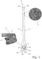
- the in Fig. 1 shown surgical clip 1comprises two rotatably interconnected, scissor-shaped clip parts 2 , 3 and a leg spring 4 to the two Clip parts 2, 3 against each other in the in Fig. 1 pretension shown closed end position.
- the two clip parts 2, 3are formed from a reinforced with Karbonkurzfasern 5 PEEK (polyetheretherketone) and the leg spring 4 from a carbon fiber reinforced with 6 PEEK.
- the clip 1is thus made of an X-ray transparent fiber composite material consisting of carbon fibers 5, 6 and PEEK material, which is approved as implant material.
- the carbon fiber fibers 6are aligned along the spring coils 7 in the leg spring 4 to give the leg spring 4 in bending stress sufficient stability.
- the one first clip part 2has a clamping arm and an operating arm 2a 2b with respect to the axis of rotation 8 opposed to each other, and between them a pivot bearing portion 9a.
- the pivot bearing portion 9ais formed as an axially open plug-in receptacle, the bottom or bottom plate 10a is annular and has on the outer circumference two opposing outer rotary guide portions 11a and therebetween each a radially inwardly recessed mounting recess 12a .
- the other, second clip part 3has a clamping arm 3a and an operating arm 3b , which lie opposite one another with respect to the axis of rotation 8, as well as a pivot bearing section 9b therebetween.
- the pivot bearing portion 9bis formed as an axially open plug-in receptacle, the bottom or bottom plate 10b is annular and on the outer circumference two opposing outer rotary guide portions 11b and therebetween each having a radially inwardly recessed mounting recess 12b .
- inner rotary guide portions 13bare provided, which face the axis of rotation 8 and are each formed by a shoulder on the clamping arm 3a and the operating arm 3b.
- a central axis of rotation 8 opening 14bis provided in the bottom plate 10b.
- the inner rotary guide portions 13bare overlapped on the opposite side of the bottom plate 10b in each case by a projection 15 and thereby formed as a guide groove.
- the second clip part 3is identical to the first clip part 2.
- the clip parts 2, 3are aligned with their two mounting recesses 12a and 12b respectively between the two outer rotary guide portions 11b and 11a of the other clip part and axially inserted into each other until they with their Base plates 10a, 10b abut each other. Subsequently, the two clip parts 2, 3 in the direction of the in Fig.
- the central opening 14a, 14b of the interconnected clip parts 2, 3form a through opening 16 , in which the leg spring 4 is arranged with its spring coils 7.
- the two spring legs 17 of the leg spring 4are integrally connected at 18 to the bottom plates 10a, 10b of the two clip parts 2, 3 by ultrasonic welding and thereby supported on the two clip parts 2, 3.
- the two clip parts 2, 3in any other way to each other directly or be indirectly rotatably mounted, so for example by a tongue and groove bearing as shown in FIGS. 12 to 16 of DE 10 2004 016 859 A1 , by a snap-in or snap-fit as in DE 103 09 491 B4 , through the leg spring 4 as in DE 199 35 418 C2 or by a molded or separate bearing sleeve as in DE 10 2013 200 127 A1 ,
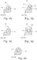
- FIGS. 4a-4eDifferent variants of the support of the two spring legs 17 on an axially projecting projection 19 of the clip parts 2, 3 are shown.
- the projection 19is integrally formed on the clip parts 2, 3 and thus also formed from reinforced with short carbon fibers 5 PEEK.
- the projection 19on the outside of the pivot bearing portion 9a, 9b, so on the bottom plate 10a, 10b, integrally formed, but may alternatively be integrally formed on the clamping arm 2a, 3a or the operating arm 2b, 3b.
- the spring leg 17is supported on the projection 19 at least in the direction of force 20 of its spring action.
- Fig. 4bis the projection 19 hook-shaped with a projection 21 and thus formed with an opposite to the direction of force 20 open groove 22 , in which the spring leg 17 is inserted and, because axially overlapped, axially fixed.
- the spring leg 17is partially positively embraced by the projection 19 and thereby fixed axially.
- the projection 19may have been remelted or deformed by a heat treatment around the spring leg 17.
- the projection 19has an axially open slot 23 , in which the spring leg 17 is inserted and thereby supported in and against the direction 20 of its spring action.
- Fig. 4eis the spring leg 17 embedded in the projection 19 completely positive fit or melted.
- the projection 19may first have a slot open on one side, the open end of the slot after the spring leg 17 has been inserted into the slot, has been remelted by a heat treatment and thereby closed.
- surgical clip 1is thus made entirely of carbon fiber reinforced PEEK, so from X-ray transparent material.
- FIGS. 5a, 5b shown clip part 2, 3serves both as a first and as a second clip part, ie, the clip is composed of two identical clip parts 2, 3.
- the projection 19is as in Fig. 4d formed with an axially open on one side slot 23, the two side walls 24 are each formed as a slot 22 toward rising ramp.
Landscapes
- Health & Medical Sciences (AREA)
- Surgery (AREA)
- Life Sciences & Earth Sciences (AREA)
- Animal Behavior & Ethology (AREA)
- Vascular Medicine (AREA)
- Veterinary Medicine (AREA)
- Public Health (AREA)
- Heart & Thoracic Surgery (AREA)
- General Health & Medical Sciences (AREA)
- Engineering & Computer Science (AREA)
- Chemical & Material Sciences (AREA)
- Epidemiology (AREA)
- Molecular Biology (AREA)
- Medical Informatics (AREA)
- Biomedical Technology (AREA)
- Nuclear Medicine, Radiotherapy & Molecular Imaging (AREA)
- Reproductive Health (AREA)
- Composite Materials (AREA)
- Materials Engineering (AREA)
- Chemical Kinetics & Catalysis (AREA)
- Surgical Instruments (AREA)
Description
Translated fromGermanDie Erfindung betrifft einen chirurgischen Clip, insbesondere Aneurysma-Clip, mit zwei drehbar miteinander verbundenen Clipteilen und mit einer Schenkelfeder, deren zwei Federschenkel jeweils an den beiden Clipteilen abgestützt sind, um die beiden Clipteile gegeneinander vorzuspannen, wobei die Schenkelfeder aus einem mit Karbonendlosfasern verstärkten Kunststoffmaterial, insbesondere PEEK, gebildet ist und die Karbonendlosfasern entlang der Federwindungen der Schenkelfeder ausgerichtet sind.The invention relates to a surgical clip, in particular aneurysm clip, with two rotatably interconnected clip parts and a leg spring whose two spring legs are respectively supported on the two clip parts to bias the two clip parts against each other, wherein the leg spring made of a carbon fiber reinforced plastic material , in particular PEEK, is formed and the Kendendendfasern along the spring turns of the leg spring are aligned.
Ein derartiger chirurgischer Clip ist beispielsweise durch den Artikel
Aus
Aus
Aus
Demgegenüber liegt der vorliegenden Erfindung die Aufgabe zugrunde, bei einem chirurgischen Clip der eingangs genannten Art die Abstützung bzw. Befestigung der Schenkelfeder an den Clipteilen zu verbessern.In contrast, the present invention has the object, in a surgical clip of the type mentioned to improve the support or attachment of the leg spring to the clip parts.
Diese Aufgabe wird erfindungsgemäß dadurch gelöst, dass die beiden Clipteile jeweils einen in Richtung der Drehachse der beiden Clipteile axial vorstehenden Vorsprung aufweisen, an dem der jeweilige Federschenkel der Schenkelfeder abgestützt ist.This object is achieved in that the two clip parts each have an axially projecting projection in the direction of the axis of rotation of the two clip parts, on which the respective spring leg of the leg spring is supported.
Die Schenkelfeder ist aus einem röntgentransparenten Faserverbundmaterial hergestellt, das aus PEEK-Material, welches als Implantatmaterial zugelassen ist, und Karbonendlosfasern besteht. Die Karbonendlosfasern sind entlang der Federwindungen ausgerichtet, um der Schenkelfeder bei Biegebeanspruchung ausreichende Stabilität zu verleihen.The leg spring is made of an X-ray transparent fiber composite material made of PEEK material, which is approved as an implant material, and Carbonendlosfasern. The carbon fiber tows are aligned along the spring turns to provide sufficient stability to the leg spring when flexed.
Besonders bevorzugt sind auch die beiden Clipteile aus einem röntgentransparenten Kunststoffmaterial, insbesondere PEEK (Polyetheretherketon), gebildet. Dabei können die beiden Clipteile vorteilhaft aus einem mit Karbonkurzfasern verstärkten Kunststoffmaterial, insbesondere PEEK, gebildet sein, also aus einem röntgentransparenten Faserverbundmaterial, in dem die Karbonkurzfasern im Gefüge ungeordnet mit dem Peek verbunden sind. In dieser Ausführung ist der gesamte Clip aus röntgentransparentem Material gebildet.Particularly preferably, the two clip parts from an X-ray transparent plastic material, in particular PEEK (polyetheretherketone) formed. In this case, the two clip parts can advantageously be formed from a plastic material reinforced with short carbon fibers, in particular PEEK, that is to say from an X-ray-transparent fiber composite material in which the short carbon fibers in the structure are connected in disorder to the peek. In this embodiment, the entire clip is made of X-ray transparent material.
Um die Schenkelfeder an den beiden Clipteilen abzustützen, können die beiden Federschenkel mit den beiden Clipteilen stoffschlüssig verbunden, insbesondere miteinander (ultraschall)verschweißt sein. Der Vorsprung kann hakenförmig ausgebildet sein, um den jeweiligen Federschenkel radial zu übergreifen und dadurch axial festzulegen, oder der jeweilige Federschenkel kann in dem Vorsprung zumindest teilweise formschlüssig eingebettet, insbesondere eingeschmolzen sein.In order to support the leg spring on the two clip parts, the two spring legs can be materially connected to the two clip parts, in particular welded together (ultrasound). The projection may be hook-shaped in order to overlap the respective spring leg radially and thereby fix it axially, or the respective spring leg can be embedded in the projection at least partially positively, in particular melted.
Vorzugsweise weisen die beiden Clipteile jeweils einen Klemmarm, einen Bedienarm und einen dazwischen befindlichen Drehlagerabschnitt mit einer Öffnung auf, wobei die Drehlagerabschnitte der beiden Clipteile drehbar ineinander gelagert sind und die Öffnungen der beiden Clipteile eine axiale Durchgangsöffnung ausbilden, in der zumindest einige der Federwindungen der Schenkelfeder angeordnet sind.Preferably, the two clip parts each have a clamping arm, an operating arm and a rotary bearing portion located therebetween with an opening, wherein the pivot bearing portions of the two clip parts are rotatably mounted in each other and the openings of the two clip parts form an axial passage opening in which at least some of the spring coils of the leg spring are arranged.
Weitere Vorteile und vorteilhafte Ausgestaltungen des Gegenstands der Erfindung ergeben sich aus der Beschreibung, den Ansprüchen und den Zeichnungen. Ebenso können die vorstehend genannten und die noch weiter aufgeführten Merkmale je für sich oder zu mehreren in beliebigen Kombinationen Verwendung finden. Die gezeigten und beschriebenen Ausführungsformen sind nicht als abschließende Aufzählung zu verstehen, sondern haben vielmehr beispielhaften Charakter für die Schilderung der Erfindung. Die vorliegende Erfindung wird durch die Merkmale des unabhängigen Anspruchs definiert. Bevorzugte Ausführungsformen sind in den abhängigen Ansprüchen angegeben. Es zeigen:
- Fig. 1
- einen chirurgischen Clip mit zwei Clipteilen und einer Schenkelfeder in seiner geschlossenen Endstellung;
- Fign. 2a, 2b
- ein erstes Clipteil des in
Fig.1 gezeigten Clips in einer Draufsicht (Fig. 2a ) und in einer Seitenansicht (Fig. 2b ); - Fign. 3a, 3b
- ein zweites Clipteil des in
Fig.1 gezeigten Clips in einer Draufsicht (Fig. 3a ) und in einer Seitenansicht (Fig. 3b ); - Fign. 4a-4e
- verschiedene Modifikationen eines an den Clipteilen jeweils vorhandenen Vorsprungs zur Abstützung der Schenkelfeder und;
- Fign. 5a, 5b
- ein weiteres Ausführungsbeispiel eines ersten oder zweiten Clip teils mit einem rampenförmigen Vorsprung in einer perspektivischen Ansicht (
Fig. 5a ) und in einer abgebrochenen Seitenansicht (Fig. 5b ).
- Fig. 1
- a surgical clip with two clip parts and a leg spring in its closed end position;
- FIGS. 2a, 2b
- a first clip part of the in
Fig.1 shown clips in a plan view (Fig. 2a ) and in a side view (Fig. 2b ); - FIGS. 3a, 3b
- a second clip part of the in
Fig.1 shown clips in a plan view (Fig. 3a ) and in a side view (Fig. 3b ); - FIGS. 4a-4e
- various modifications of a clip on the parts respectively existing projection for supporting the leg spring and;
- FIGS. 5a, 5b
- Another embodiment of a first or second clip part with a ramp-shaped projection in a perspective view (
Fig. 5a ) and in a broken side view (Fig. 5b ).
Der in
Die beiden Clipteile 2, 3 sind aus einem mit Karbonkurzfasern5 verstärkten PEEK (Polyetheretherketon) und die Schenkelfeder 4 aus einem mit Karbonendlosfasern6 verstärkten PEEK gebildet. Der Clip 1 ist somit aus einem röntgentransparenten Faserverbundmaterial hergestellt, das aus Karbonfasern 5, 6 und PEEK-Material, welches als Implantatmaterial zugelassen ist, besteht. Im Gegensatz zu den beiden Clipteilen 2, 3, in denen die Karbonkurzfasern 5 im Gefüge ungeordnet mit dem Peek verbunden sind, sind bei der Schenkelfeder 4 die Karbonendlosfasern 6 entlang den Federwindungen7 ausgerichtet, um der Schenkelfeder 4 bei Biegebeanspruchung ausreichende Stabilität zu verleihen.The two
Wie in
Wie in
Zum Verbinden der beiden Clipteile 2, 3 zum chirurgische Clip 1 werden die Clipteile 2, 3 mit ihren beiden Montageaussparungen 12a bzw. 12b jeweils zwischen den beiden äußere Drehführungsabschnitte 11b bzw. 11a des jeweils anderen Clipteils ausgerichtet und axial ineinander gesteckt, bis sie mit ihren Bodenplatten 10a, 10b aneinander anliegen. Anschließend werden die beiden Clipteile 2, 3 in Richtung auf die in
Die zentrischen Öffnung 14a, 14b der miteinander verbundenen Clipteile 2, 3 bilden eine Durchgangsöffnung16, in der die Schenkelfeder 4 mit ihren Federwindungen 7 angeordnet ist. Die beiden Federschenkel17 der Schenkelfeder 4 sind bei18 mit den Bodenplatten 10a, 10b der beiden Clipteilen 2, 3 durch Ultraschallschweißen stoffschlüssig verbunden und dadurch an den beiden Clipteilen 2, 3 abgestützt. Mithilfe einer zwischen die beiden Bedienarme 2b, 3b greifenden Anlegezange können die Bedienarme 2b, 3b gegen die Kraft der Schenkelfeder 4 auseinandergedrückt und dadurch die Klemmarme 2a, 3a geöffnet werden.The
Statt der in
In
In
In
In
In
In
Der in
Das in
Claims (7)
- Surgical clip (1), in particular an aneurysm clip, comprising two rotatably interconnected clip parts (2, 3) and a leg spring (4), the two spring legs (17) of which are in each case supported on the two clip parts (2, 3) so as to mutually pretension the two clip parts (2, 3),
wherein the leg spring (4) is formed from a plastics material, in particular PEEK, that is reinforced with continuous carbon fibers (6), and the continuous carbon fibers (6) are aligned along the spring coilings (7) of the leg spring (4),
characterized in that the two clip parts (2, 3) have in each case one protrusion (19) which axially protrudes in the direction of the axis of rotation (8) of the two clip parts (2, 3) and on which the respective spring leg (17) of the leg spring (4) is supported. - Surgical clip according to claim 1,characterized in that the protrusion (19) is configured so as to be hook-shaped and engages radially across the respective spring leg (17).
- Surgical clip according to claim 1,characterized in that the respective spring leg (17) is at least partially embedded in the protrusion (19) in a form-fitting manner, in particular is melted therein.
- Surgical clip according to any one of the preceding claims,characterized in that the two clip parts (2, 3) are formed from a plastics material, in particular PEEK.
- Surgical clip according to any one of the preceding claims,characterized in that the two clip parts (2, 3) are formed from a plastics material, in particular PEEK, which is reinforced with short carbon fibers (5).
- Surgical clip according to claim 4 or 5,characterized in that the two spring legs (17) of the leg spring (4) are connected to the two clip parts (2, 3) in a materially integral manner, in particular are welded to one another.
- Surgical clip according to one of the preceding claims,characterized in that the two clip parts (2, 3) have in each case one clamping arm (2a, 3a), one operating arm (2b, 3b), and a rotary bearing portion (9a, 9b) located therebetween, said rotary bearing portion (9a, 9b) having an opening (14a, 14b), wherein the rotary bearing portions (9a, 9b) of the two clip parts (2, 3) are mounted so as to be rotatable within one another, and the openings (14a, 14b) of the two clip parts (2, 3) form an axial passage opening (16) in which at least some of the spring coilings (7) of the leg spring (4) are disposed.
Priority Applications (2)
| Application Number | Priority Date | Filing Date | Title |
|---|---|---|---|
| EP17193622.2AEP3461435B1 (en) | 2017-09-28 | 2017-09-28 | Surgical clip made from carbon fibre reinforced plastic material |
| US16/138,974US10863991B2 (en) | 2017-09-28 | 2018-09-22 | Surgical clip made of carbon fiber reinforced plastic material |
Applications Claiming Priority (1)
| Application Number | Priority Date | Filing Date | Title |
|---|---|---|---|
| EP17193622.2AEP3461435B1 (en) | 2017-09-28 | 2017-09-28 | Surgical clip made from carbon fibre reinforced plastic material |
Publications (2)
| Publication Number | Publication Date |
|---|---|
| EP3461435A1 EP3461435A1 (en) | 2019-04-03 |
| EP3461435B1true EP3461435B1 (en) | 2019-09-04 |
Family
ID=59974278
Family Applications (1)
| Application Number | Title | Priority Date | Filing Date |
|---|---|---|---|
| EP17193622.2AActiveEP3461435B1 (en) | 2017-09-28 | 2017-09-28 | Surgical clip made from carbon fibre reinforced plastic material |
Country Status (2)
| Country | Link |
|---|---|
| US (1) | US10863991B2 (en) |
| EP (1) | EP3461435B1 (en) |
Families Citing this family (1)
| Publication number | Priority date | Publication date | Assignee | Title |
|---|---|---|---|---|
| FR3141847B1 (en)* | 2022-11-11 | 2025-06-06 | Xavier Renard | element for making a vascular clamp and vascular clamp thus made |
Citations (2)
| Publication number | Priority date | Publication date | Assignee | Title |
|---|---|---|---|---|
| DE19935418C2 (en)* | 1999-07-28 | 2001-07-12 | Aesculap Ag & Co Kg | Surgical clip |
| DE102013107876A1 (en)* | 2013-07-23 | 2015-01-29 | Aesculap Ag | Surgical clip, especially aneurysm clip |
Family Cites Families (6)
| Publication number | Priority date | Publication date | Assignee | Title |
|---|---|---|---|---|
| US4932955A (en)* | 1984-06-29 | 1990-06-12 | Baxter International Inc. | Clip |
| DE10309491B8 (en) | 2003-02-26 | 2005-09-08 | Aesculap Ag & Co. Kg | Surgical clip |
| DE102004016859B4 (en) | 2004-04-04 | 2015-08-27 | Peter Lazic Gmbh | Aneurysm clip |
| DE102009003273B4 (en) | 2009-05-20 | 2018-12-20 | Lazic Besitz GmbH & Co. KG | Aneurysm clip |
| DE102013200127A1 (en)* | 2013-01-08 | 2014-07-10 | Peter Lazic Gmbh | Aneurysm clip |
| ES2575727B1 (en)* | 2014-12-30 | 2017-04-12 | Neos Surgery, S.L. | Aneurysm clamp |
- 2017
- 2017-09-28EPEP17193622.2Apatent/EP3461435B1/enactiveActive
- 2018
- 2018-09-22USUS16/138,974patent/US10863991B2/enactiveActive
Patent Citations (2)
| Publication number | Priority date | Publication date | Assignee | Title |
|---|---|---|---|---|
| DE19935418C2 (en)* | 1999-07-28 | 2001-07-12 | Aesculap Ag & Co Kg | Surgical clip |
| DE102013107876A1 (en)* | 2013-07-23 | 2015-01-29 | Aesculap Ag | Surgical clip, especially aneurysm clip |
Also Published As
| Publication number | Publication date |
|---|---|
| EP3461435A1 (en) | 2019-04-03 |
| US10863991B2 (en) | 2020-12-15 |
| US20190090880A1 (en) | 2019-03-28 |
Similar Documents
| Publication | Publication Date | Title |
|---|---|---|
| DE8911948U1 (en) | Clamp for clamping blood vessels or aneurysms | |
| DE4028892C2 (en) | ||
| AT406201B (en) | HINGE JOINT BETWEEN A BRACKET AND A BRACKED JAW OF A FRAME | |
| DE202024101589U1 (en) | Single-axis header assembly for one implant | |
| EP2752164B1 (en) | Aneurysm clip | |
| EP1395757A1 (en) | Joint, particularly a ball-and-socket joint for chassis parts in a motor vehicle | |
| EP2852335B1 (en) | Surgical clip, in particular aneurysm clip | |
| DE2954560C2 (en) | ||
| EP3461435B1 (en) | Surgical clip made from carbon fibre reinforced plastic material | |
| DE2846299A1 (en) | HEART VALVE PROSTHESIS AND METHOD OF MANUFACTURING AND ASSEMBLING THE SAME | |
| EP2589346B1 (en) | Pre-tensioned aneurysm clip | |
| EP2929843B1 (en) | Surgical clip with three clamping arms | |
| WO2019238711A1 (en) | Centrifuge | |
| EP2214596B1 (en) | Implant | |
| EP3383319B1 (en) | Intraocular lens having a stiffened haptic | |
| DE202011051881U1 (en) | Prestressed aneurysm clip | |
| DE102004056265A1 (en) | Rifle | |
| EP3461434B1 (en) | Surgical clip with bearing sleeve | |
| DE102021101134A1 (en) | coupling arrangement | |
| DE112020000951T5 (en) | Shock absorbers | |
| EP2716932A2 (en) | Tension spring | |
| DE102018202276B4 (en) | Liquid pump with vibration damping element | |
| WO2003038240A1 (en) | Securing device for the moving blades of axial flow turbomachines | |
| AT518214B1 (en) | Hinge joint for a pair of glasses | |
| DE102004042216B4 (en) | Self-retaining hose socket for attaching a cable to an abutment |
Legal Events
| Date | Code | Title | Description |
|---|---|---|---|
| STAA | Information on the status of an ep patent application or granted ep patent | Free format text:STATUS: EXAMINATION IS IN PROGRESS | |
| PUAI | Public reference made under article 153(3) epc to a published international application that has entered the european phase | Free format text:ORIGINAL CODE: 0009012 | |
| 17P | Request for examination filed | Effective date:20180815 | |
| AK | Designated contracting states | Kind code of ref document:A1 Designated state(s):AL AT BE BG CH CY CZ DE DK EE ES FI FR GB GR HR HU IE IS IT LI LT LU LV MC MK MT NL NO PL PT RO RS SE SI SK SM TR | |
| AX | Request for extension of the european patent | Extension state:BA ME | |
| GRAJ | Information related to disapproval of communication of intention to grant by the applicant or resumption of examination proceedings by the epo deleted | Free format text:ORIGINAL CODE: EPIDOSDIGR1 | |
| STAA | Information on the status of an ep patent application or granted ep patent | Free format text:STATUS: GRANT OF PATENT IS INTENDED | |
| GRAP | Despatch of communication of intention to grant a patent | Free format text:ORIGINAL CODE: EPIDOSNIGR1 | |
| RIC1 | Information provided on ipc code assigned before grant | Ipc:A61B 17/00 20060101ALN20190404BHEP Ipc:A61B 17/122 20060101AFI20190404BHEP | |
| INTG | Intention to grant announced | Effective date:20190423 | |
| GRAS | Grant fee paid | Free format text:ORIGINAL CODE: EPIDOSNIGR3 | |
| GRAA | (expected) grant | Free format text:ORIGINAL CODE: 0009210 | |
| STAA | Information on the status of an ep patent application or granted ep patent | Free format text:STATUS: THE PATENT HAS BEEN GRANTED | |
| AK | Designated contracting states | Kind code of ref document:B1 Designated state(s):AL AT BE BG CH CY CZ DE DK EE ES FI FR GB GR HR HU IE IS IT LI LT LU LV MC MK MT NL NO PL PT RO RS SE SI SK SM TR | |
| REG | Reference to a national code | Ref country code:GB Ref legal event code:FG4D Free format text:NOT ENGLISH | |
| REG | Reference to a national code | Ref country code:CH Ref legal event code:EP | |
| REG | Reference to a national code | Ref country code:AT Ref legal event code:REF Ref document number:1174257 Country of ref document:AT Kind code of ref document:T Effective date:20190915 | |
| REG | Reference to a national code | Ref country code:DE Ref legal event code:R096 Ref document number:502017002201 Country of ref document:DE | |
| REG | Reference to a national code | Ref country code:CH Ref legal event code:NV Representative=s name:RIEDERER HASLER AND PARTNER PATENTANWAELTE AG, LI | |
| REG | Reference to a national code | Ref country code:IE Ref legal event code:FG4D Free format text:LANGUAGE OF EP DOCUMENT: GERMAN | |
| REG | Reference to a national code | Ref country code:NL Ref legal event code:MP Effective date:20190904 | |
| REG | Reference to a national code | Ref country code:LT Ref legal event code:MG4D | |
| PG25 | Lapsed in a contracting state [announced via postgrant information from national office to epo] | Ref country code:HR Free format text:LAPSE BECAUSE OF FAILURE TO SUBMIT A TRANSLATION OF THE DESCRIPTION OR TO PAY THE FEE WITHIN THE PRESCRIBED TIME-LIMIT Effective date:20190904 Ref country code:LT Free format text:LAPSE BECAUSE OF FAILURE TO SUBMIT A TRANSLATION OF THE DESCRIPTION OR TO PAY THE FEE WITHIN THE PRESCRIBED TIME-LIMIT Effective date:20190904 Ref country code:SE Free format text:LAPSE BECAUSE OF FAILURE TO SUBMIT A TRANSLATION OF THE DESCRIPTION OR TO PAY THE FEE WITHIN THE PRESCRIBED TIME-LIMIT Effective date:20190904 Ref country code:BG Free format text:LAPSE BECAUSE OF FAILURE TO SUBMIT A TRANSLATION OF THE DESCRIPTION OR TO PAY THE FEE WITHIN THE PRESCRIBED TIME-LIMIT Effective date:20191204 Ref country code:FI Free format text:LAPSE BECAUSE OF FAILURE TO SUBMIT A TRANSLATION OF THE DESCRIPTION OR TO PAY THE FEE WITHIN THE PRESCRIBED TIME-LIMIT Effective date:20190904 Ref country code:NO Free format text:LAPSE BECAUSE OF FAILURE TO SUBMIT A TRANSLATION OF THE DESCRIPTION OR TO PAY THE FEE WITHIN THE PRESCRIBED TIME-LIMIT Effective date:20191204 | |
| PG25 | Lapsed in a contracting state [announced via postgrant information from national office to epo] | Ref country code:RS Free format text:LAPSE BECAUSE OF FAILURE TO SUBMIT A TRANSLATION OF THE DESCRIPTION OR TO PAY THE FEE WITHIN THE PRESCRIBED TIME-LIMIT Effective date:20190904 Ref country code:GR Free format text:LAPSE BECAUSE OF FAILURE TO SUBMIT A TRANSLATION OF THE DESCRIPTION OR TO PAY THE FEE WITHIN THE PRESCRIBED TIME-LIMIT Effective date:20191205 Ref country code:LV Free format text:LAPSE BECAUSE OF FAILURE TO SUBMIT A TRANSLATION OF THE DESCRIPTION OR TO PAY THE FEE WITHIN THE PRESCRIBED TIME-LIMIT Effective date:20190904 Ref country code:AL Free format text:LAPSE BECAUSE OF FAILURE TO SUBMIT A TRANSLATION OF THE DESCRIPTION OR TO PAY THE FEE WITHIN THE PRESCRIBED TIME-LIMIT Effective date:20190904 Ref country code:ES Free format text:LAPSE BECAUSE OF FAILURE TO SUBMIT A TRANSLATION OF THE DESCRIPTION OR TO PAY THE FEE WITHIN THE PRESCRIBED TIME-LIMIT Effective date:20190904 | |
| PG25 | Lapsed in a contracting state [announced via postgrant information from national office to epo] | Ref country code:NL Free format text:LAPSE BECAUSE OF FAILURE TO SUBMIT A TRANSLATION OF THE DESCRIPTION OR TO PAY THE FEE WITHIN THE PRESCRIBED TIME-LIMIT Effective date:20190904 Ref country code:PT Free format text:LAPSE BECAUSE OF FAILURE TO SUBMIT A TRANSLATION OF THE DESCRIPTION OR TO PAY THE FEE WITHIN THE PRESCRIBED TIME-LIMIT Effective date:20200106 Ref country code:PL Free format text:LAPSE BECAUSE OF FAILURE TO SUBMIT A TRANSLATION OF THE DESCRIPTION OR TO PAY THE FEE WITHIN THE PRESCRIBED TIME-LIMIT Effective date:20190904 Ref country code:IT Free format text:LAPSE BECAUSE OF FAILURE TO SUBMIT A TRANSLATION OF THE DESCRIPTION OR TO PAY THE FEE WITHIN THE PRESCRIBED TIME-LIMIT Effective date:20190904 Ref country code:RO Free format text:LAPSE BECAUSE OF FAILURE TO SUBMIT A TRANSLATION OF THE DESCRIPTION OR TO PAY THE FEE WITHIN THE PRESCRIBED TIME-LIMIT Effective date:20190904 Ref country code:EE Free format text:LAPSE BECAUSE OF FAILURE TO SUBMIT A TRANSLATION OF THE DESCRIPTION OR TO PAY THE FEE WITHIN THE PRESCRIBED TIME-LIMIT Effective date:20190904 | |
| PG25 | Lapsed in a contracting state [announced via postgrant information from national office to epo] | Ref country code:SM Free format text:LAPSE BECAUSE OF FAILURE TO SUBMIT A TRANSLATION OF THE DESCRIPTION OR TO PAY THE FEE WITHIN THE PRESCRIBED TIME-LIMIT Effective date:20190904 Ref country code:IS Free format text:LAPSE BECAUSE OF FAILURE TO SUBMIT A TRANSLATION OF THE DESCRIPTION OR TO PAY THE FEE WITHIN THE PRESCRIBED TIME-LIMIT Effective date:20200224 Ref country code:CZ Free format text:LAPSE BECAUSE OF FAILURE TO SUBMIT A TRANSLATION OF THE DESCRIPTION OR TO PAY THE FEE WITHIN THE PRESCRIBED TIME-LIMIT Effective date:20190904 Ref country code:SK Free format text:LAPSE BECAUSE OF FAILURE TO SUBMIT A TRANSLATION OF THE DESCRIPTION OR TO PAY THE FEE WITHIN THE PRESCRIBED TIME-LIMIT Effective date:20190904 | |
| REG | Reference to a national code | Ref country code:DE Ref legal event code:R097 Ref document number:502017002201 Country of ref document:DE | |
| PLBE | No opposition filed within time limit | Free format text:ORIGINAL CODE: 0009261 | |
| STAA | Information on the status of an ep patent application or granted ep patent | Free format text:STATUS: NO OPPOSITION FILED WITHIN TIME LIMIT | |
| PG2D | Information on lapse in contracting state deleted | Ref country code:IS | |
| PG25 | Lapsed in a contracting state [announced via postgrant information from national office to epo] | Ref country code:DK Free format text:LAPSE BECAUSE OF FAILURE TO SUBMIT A TRANSLATION OF THE DESCRIPTION OR TO PAY THE FEE WITHIN THE PRESCRIBED TIME-LIMIT Effective date:20190904 Ref country code:IE Free format text:LAPSE BECAUSE OF NON-PAYMENT OF DUE FEES Effective date:20190928 Ref country code:LU Free format text:LAPSE BECAUSE OF NON-PAYMENT OF DUE FEES Effective date:20190928 Ref country code:IS Free format text:LAPSE BECAUSE OF FAILURE TO SUBMIT A TRANSLATION OF THE DESCRIPTION OR TO PAY THE FEE WITHIN THE PRESCRIBED TIME-LIMIT Effective date:20200105 | |
| REG | Reference to a national code | Ref country code:BE Ref legal event code:MM Effective date:20190930 | |
| 26N | No opposition filed | Effective date:20200605 | |
| PG25 | Lapsed in a contracting state [announced via postgrant information from national office to epo] | Ref country code:BE Free format text:LAPSE BECAUSE OF NON-PAYMENT OF DUE FEES Effective date:20190930 Ref country code:MC Free format text:LAPSE BECAUSE OF FAILURE TO SUBMIT A TRANSLATION OF THE DESCRIPTION OR TO PAY THE FEE WITHIN THE PRESCRIBED TIME-LIMIT Effective date:20190904 | |
| PG25 | Lapsed in a contracting state [announced via postgrant information from national office to epo] | Ref country code:CY Free format text:LAPSE BECAUSE OF FAILURE TO SUBMIT A TRANSLATION OF THE DESCRIPTION OR TO PAY THE FEE WITHIN THE PRESCRIBED TIME-LIMIT Effective date:20190904 | |
| PG25 | Lapsed in a contracting state [announced via postgrant information from national office to epo] | Ref country code:MT Free format text:LAPSE BECAUSE OF FAILURE TO SUBMIT A TRANSLATION OF THE DESCRIPTION OR TO PAY THE FEE WITHIN THE PRESCRIBED TIME-LIMIT Effective date:20190904 Ref country code:HU Free format text:LAPSE BECAUSE OF FAILURE TO SUBMIT A TRANSLATION OF THE DESCRIPTION OR TO PAY THE FEE WITHIN THE PRESCRIBED TIME-LIMIT; INVALID AB INITIO Effective date:20170928 | |
| PG25 | Lapsed in a contracting state [announced via postgrant information from national office to epo] | Ref country code:SI Free format text:LAPSE BECAUSE OF FAILURE TO SUBMIT A TRANSLATION OF THE DESCRIPTION OR TO PAY THE FEE WITHIN THE PRESCRIBED TIME-LIMIT Effective date:20190904 | |
| PG25 | Lapsed in a contracting state [announced via postgrant information from national office to epo] | Ref country code:TR Free format text:LAPSE BECAUSE OF FAILURE TO SUBMIT A TRANSLATION OF THE DESCRIPTION OR TO PAY THE FEE WITHIN THE PRESCRIBED TIME-LIMIT Effective date:20190904 | |
| PG25 | Lapsed in a contracting state [announced via postgrant information from national office to epo] | Ref country code:MK Free format text:LAPSE BECAUSE OF FAILURE TO SUBMIT A TRANSLATION OF THE DESCRIPTION OR TO PAY THE FEE WITHIN THE PRESCRIBED TIME-LIMIT Effective date:20190904 | |
| PGFP | Annual fee paid to national office [announced via postgrant information from national office to epo] | Ref country code:DE Payment date:20240912 Year of fee payment:8 | |
| PGFP | Annual fee paid to national office [announced via postgrant information from national office to epo] | Ref country code:GB Payment date:20240923 Year of fee payment:8 | |
| PGFP | Annual fee paid to national office [announced via postgrant information from national office to epo] | Ref country code:FR Payment date:20240924 Year of fee payment:8 | |
| PGFP | Annual fee paid to national office [announced via postgrant information from national office to epo] | Ref country code:AT Payment date:20240918 Year of fee payment:8 | |
| PGFP | Annual fee paid to national office [announced via postgrant information from national office to epo] | Ref country code:CH Payment date:20241001 Year of fee payment:8 |