EP3460550B1 - Multi-fiber fiber optic connector - Google Patents
Multi-fiber fiber optic connectorDownload PDFInfo
- Publication number
- EP3460550B1 EP3460550B1EP18197868.5AEP18197868AEP3460550B1EP 3460550 B1EP3460550 B1EP 3460550B1EP 18197868 AEP18197868 AEP 18197868AEP 3460550 B1EP3460550 B1EP 3460550B1
- Authority
- EP
- European Patent Office
- Prior art keywords
- fiber optic
- connector
- fiber
- cable
- connector body
- Prior art date
- Legal status (The legal status is an assumption and is not a legal conclusion. Google has not performed a legal analysis and makes no representation as to the accuracy of the status listed.)
- Active
Links
Images


Classifications
- G—PHYSICS
- G02—OPTICS
- G02B—OPTICAL ELEMENTS, SYSTEMS OR APPARATUS
- G02B6/00—Light guides; Structural details of arrangements comprising light guides and other optical elements, e.g. couplings
- G02B6/24—Coupling light guides
- G02B6/36—Mechanical coupling means
- G02B6/38—Mechanical coupling means having fibre to fibre mating means
- G02B6/3807—Dismountable connectors, i.e. comprising plugs
- G02B6/3873—Connectors using guide surfaces for aligning ferrule ends, e.g. tubes, sleeves, V-grooves, rods, pins, balls
- G02B6/3885—Multicore or multichannel optical connectors, i.e. one single ferrule containing more than one fibre, e.g. ribbon type
- G—PHYSICS
- G02—OPTICS
- G02B—OPTICAL ELEMENTS, SYSTEMS OR APPARATUS
- G02B6/00—Light guides; Structural details of arrangements comprising light guides and other optical elements, e.g. couplings
- G02B6/24—Coupling light guides
- G02B6/36—Mechanical coupling means
- G02B6/38—Mechanical coupling means having fibre to fibre mating means
- G02B6/3807—Dismountable connectors, i.e. comprising plugs
- G02B6/381—Dismountable connectors, i.e. comprising plugs of the ferrule type, e.g. fibre ends embedded in ferrules, connecting a pair of fibres
- G02B6/3818—Dismountable connectors, i.e. comprising plugs of the ferrule type, e.g. fibre ends embedded in ferrules, connecting a pair of fibres of a low-reflection-loss type
- G02B6/3821—Dismountable connectors, i.e. comprising plugs of the ferrule type, e.g. fibre ends embedded in ferrules, connecting a pair of fibres of a low-reflection-loss type with axial spring biasing or loading means
- G—PHYSICS
- G02—OPTICS
- G02B—OPTICAL ELEMENTS, SYSTEMS OR APPARATUS
- G02B6/00—Light guides; Structural details of arrangements comprising light guides and other optical elements, e.g. couplings
- G02B6/24—Coupling light guides
- G02B6/36—Mechanical coupling means
- G02B6/38—Mechanical coupling means having fibre to fibre mating means
- G02B6/3807—Dismountable connectors, i.e. comprising plugs
- G02B6/3887—Anchoring optical cables to connector housings, e.g. strain relief features
- G02B6/3888—Protection from over-extension or over-compression
- G—PHYSICS
- G02—OPTICS
- G02B—OPTICAL ELEMENTS, SYSTEMS OR APPARATUS
- G02B6/00—Light guides; Structural details of arrangements comprising light guides and other optical elements, e.g. couplings
- G02B6/44—Mechanical structures for providing tensile strength and external protection for fibres, e.g. optical transmission cables
- G02B6/4401—Optical cables
- G02B6/4403—Optical cables with ribbon structure
- G—PHYSICS
- G02—OPTICS
- G02B—OPTICAL ELEMENTS, SYSTEMS OR APPARATUS
- G02B6/00—Light guides; Structural details of arrangements comprising light guides and other optical elements, e.g. couplings
- G02B6/44—Mechanical structures for providing tensile strength and external protection for fibres, e.g. optical transmission cables
- G02B6/4401—Optical cables
- G02B6/4429—Means specially adapted for strengthening or protecting the cables
- G—PHYSICS
- G02—OPTICS
- G02B—OPTICAL ELEMENTS, SYSTEMS OR APPARATUS
- G02B6/00—Light guides; Structural details of arrangements comprising light guides and other optical elements, e.g. couplings
- G02B6/24—Coupling light guides
- G02B6/255—Splicing of light guides, e.g. by fusion or bonding
- G02B6/2558—Reinforcement of splice joint
- G—PHYSICS
- G02—OPTICS
- G02B—OPTICAL ELEMENTS, SYSTEMS OR APPARATUS
- G02B6/00—Light guides; Structural details of arrangements comprising light guides and other optical elements, e.g. couplings
- G02B6/24—Coupling light guides
- G02B6/36—Mechanical coupling means
- G02B6/38—Mechanical coupling means having fibre to fibre mating means
- G02B6/3807—Dismountable connectors, i.e. comprising plugs
- G02B6/381—Dismountable connectors, i.e. comprising plugs of the ferrule type, e.g. fibre ends embedded in ferrules, connecting a pair of fibres
- G02B6/3825—Dismountable connectors, i.e. comprising plugs of the ferrule type, e.g. fibre ends embedded in ferrules, connecting a pair of fibres with an intermediate part, e.g. adapter, receptacle, linking two plugs
- G—PHYSICS
- G02—OPTICS
- G02B—OPTICAL ELEMENTS, SYSTEMS OR APPARATUS
- G02B6/00—Light guides; Structural details of arrangements comprising light guides and other optical elements, e.g. couplings
- G02B6/24—Coupling light guides
- G02B6/36—Mechanical coupling means
- G02B6/38—Mechanical coupling means having fibre to fibre mating means
- G02B6/3807—Dismountable connectors, i.e. comprising plugs
- G02B6/3833—Details of mounting fibres in ferrules; Assembly methods; Manufacture
- G02B6/3846—Details of mounting fibres in ferrules; Assembly methods; Manufacture with fibre stubs
- G—PHYSICS
- G02—OPTICS
- G02B—OPTICAL ELEMENTS, SYSTEMS OR APPARATUS
- G02B6/00—Light guides; Structural details of arrangements comprising light guides and other optical elements, e.g. couplings
- G02B6/24—Coupling light guides
- G02B6/36—Mechanical coupling means
- G02B6/38—Mechanical coupling means having fibre to fibre mating means
- G02B6/3807—Dismountable connectors, i.e. comprising plugs
- G02B6/3869—Mounting ferrules to connector body, i.e. plugs
- G02B6/387—Connector plugs comprising two complementary members, e.g. shells, caps, covers, locked together
- G—PHYSICS
- G02—OPTICS
- G02B—OPTICAL ELEMENTS, SYSTEMS OR APPARATUS
- G02B6/00—Light guides; Structural details of arrangements comprising light guides and other optical elements, e.g. couplings
- G02B6/24—Coupling light guides
- G02B6/36—Mechanical coupling means
- G02B6/38—Mechanical coupling means having fibre to fibre mating means
- G02B6/3807—Dismountable connectors, i.e. comprising plugs
- G02B6/3887—Anchoring optical cables to connector housings, e.g. strain relief features
- G02B6/3889—Anchoring optical cables to connector housings, e.g. strain relief features using encapsulation for protection, e.g. adhesive, molding or casting resin
- G—PHYSICS
- G02—OPTICS
- G02B—OPTICAL ELEMENTS, SYSTEMS OR APPARATUS
- G02B6/00—Light guides; Structural details of arrangements comprising light guides and other optical elements, e.g. couplings
- G02B6/24—Coupling light guides
- G02B6/36—Mechanical coupling means
- G02B6/38—Mechanical coupling means having fibre to fibre mating means
- G02B6/3807—Dismountable connectors, i.e. comprising plugs
- G02B6/389—Dismountable connectors, i.e. comprising plugs characterised by the method of fastening connecting plugs and sockets, e.g. screw- or nut-lock, snap-in, bayonet type
- G02B6/3891—Bayonet type
- G—PHYSICS
- G02—OPTICS
- G02B—OPTICAL ELEMENTS, SYSTEMS OR APPARATUS
- G02B6/00—Light guides; Structural details of arrangements comprising light guides and other optical elements, e.g. couplings
- G02B6/24—Coupling light guides
- G02B6/36—Mechanical coupling means
- G02B6/38—Mechanical coupling means having fibre to fibre mating means
- G02B6/3807—Dismountable connectors, i.e. comprising plugs
- G02B6/389—Dismountable connectors, i.e. comprising plugs characterised by the method of fastening connecting plugs and sockets, e.g. screw- or nut-lock, snap-in, bayonet type
- G02B6/3894—Screw-lock type
- G—PHYSICS
- G02—OPTICS
- G02B—OPTICAL ELEMENTS, SYSTEMS OR APPARATUS
- G02B6/00—Light guides; Structural details of arrangements comprising light guides and other optical elements, e.g. couplings
- G02B6/24—Coupling light guides
- G02B6/36—Mechanical coupling means
- G02B6/40—Mechanical coupling means having fibre bundle mating means
- G02B6/406—Mechanical coupling means having fibre bundle mating means of the ferrule type, connecting a plurality of pairs of ferrules
- G—PHYSICS
- G02—OPTICS
- G02B—OPTICAL ELEMENTS, SYSTEMS OR APPARATUS
- G02B6/00—Light guides; Structural details of arrangements comprising light guides and other optical elements, e.g. couplings
- G02B6/44—Mechanical structures for providing tensile strength and external protection for fibres, e.g. optical transmission cables
- G02B6/4401—Optical cables
- G02B6/4429—Means specially adapted for strengthening or protecting the cables
- G02B6/44384—Means specially adapted for strengthening or protecting the cables the means comprising water blocking or hydrophobic materials
Definitions
- the present disclosurerelates generally to a fiber optic connector arrangement.
- Fiber optic communication systemsare becoming prevalent in part because service providers want to deliver high bandwidth communication capabilities (e.g., data and voice) to customers.
- Fiber optic communication systemsemploy a network of fiber optic cables to transmit large volumes of data and voice signals over relatively long distances.
- Optical fiber connectorsare an important part of most fiber optic communication systems. Fiber optic connectors allow two optical fibers to be quickly optically connected without requiring a splice. Fiber optic connectors can be used to optically interconnect two lengths of optical fiber. Fiber optic connectors can also be used to interconnect lengths of optical fiber to passive and active equipment.
- a typical fiber optic connectorincludes a ferrule assembly supported at a distal end of a connector housing.
- a springis used to bias the ferrule assembly in a distal direction relative to the connector housing.
- the ferrulefunctions to support an end portion of at least one optical fiber (in the case of a multi-fiber ferrule, the ends of multiple fibers are supported).
- the ferrulehas a distal end face at which a polished end of the optical fiber is located.
- connection systemshave been developed for use in outside environments. Such connection systems typically have a ruggedized/hardened construction adapted for accommodating substantial pull-out forces. Such connection systems are also typically sealed to limit moisture intrusion.
- Example fiber optic connection systems adapted for outside useare disclosed in U.S. Patent Nos. 6648520 , 7,264,402 , 7572065 , 7744288 , 7762726 , 7744286 , 7942590 .
- US 2011/0280525 A1discloses implementation techniques for splicing together at least two optical fibers of at least two cable segments in particular for splicing together two different types of fiber optic cable segments.
- Each cable segmentincludes at least one optical fiber.
- a second end of the second cable segmentis terminated at a fiber optic connector arrangement, e.g. a multifiber connector.
- Splicing the second cable segment to the first cable segmentoptically couples together the optical fibers of the cable segments at a splice location.
- the fused optical fibers at the splice locationare protected within a splice enclosure arrangement.
- US 6,173,097 B1discloses a multifiber connector which includes a multifile ferrule, splice components and a crimp tube that define a lengthwise extending passageway having a lateral cross-sectional shape that is generally oval for receiving and maintaining a plurality of optical fibers in a lateral side-by-side relationship.
- the crimp tubetherefore provides the optical fibers to the splice components in an aligned and properly spaced manner.
- Multi-fiber connectorscan include splice-on configurations and direct termination configurations.
- a splice-on configurationoptical fibers are pre-terminated within a multi-fiber ferrule and the end face of the ferrule is processed (e.g., polished and shaped as needed). After processing of the ferrule, the optical fibers have polished end faces at a front of the ferrule and also have pigtails that project rearwardly from the ferrule.
- the multi-fiber ferruleis loaded into a connector and the pigtails are spliced to optical fibers corresponding to a fiber optic cable desired to be coupled to the connector.
- the splice locationis positioned rearward of the connector (e.g., see U.S.
- the inventionis defined by a fiber optic connector arrangement with the features of claims 1.
- the fiber optic connector 110may be part of a hardened (i.e., environmentally sealed) fiber optic connector arrangement 108.
- the fiber optic connector arrangement 108is configured to interface with a second fiber optic cable assembly 200.
- the second fiber optic cable assembly 200includes a multi-fiber connector 210 terminating a second fiber optic cable 205.
- the fiber optic connector arrangement 108is configured to couple to a fiber optic adapter 150 to enable connection to the fiber optic connector 210 of the second fiber optic cable assembly 200.
- the example adapter 150enables a first fiber optic connector 110, which terminates a first optical cable 105, to mate with a second optic connector 210, which terminates a second optical cable 205.
- the adapter 150defines a socket configured to receive a connectorized end of the second cable assembly 200.
- the fiber optic adapter 150is configured to mount within an opening defined in a wall, plate, enclosure, or other structure.
- the fiber optic connector arrangement 108is a hardened (i.e., environmentally sealed) fiber optic connector arrangement 108.
- the adapter 150is a hardened (i.e., environmentally sealed) adapter.
- the adapter 150enables the hardened fiber optic connector arrangement 108 to mate with a non-hardened (i.e., unsealed) fiber optic connector 210.
- the adapter 150 coupled to the hardened fiber optic connector arrangement 108is configured to receive a non-hardened fiber optic connector 210 (e.g., an MPO connector).
- a non-hardened fiber optic connector 210e.g., an MPO connector
- Certain types of hardened fiber optic connector arrangements 108are configured to mate with other hardened fiber optic connector arrangements (e.g., in a plug and receptacle style connection).
- FIG. 2shows one example fiber optic cable 105 including one or more optical fibers 106 surrounded by an outer jacket 107.
- the outer jacket 107has an elongated transverse cross-sectional profile defining a major axis A1 and a minor axis A2.
- the transverse cross-sectional profile defined by the outer jacket 107is generally rectangular with rounded ends.
- the major axis A1 and the minor axis A2intersect perpendicularly at a lengthwise axis of the cable 105.
- the transverse cross-sectional profilehas maximum width that extends along the major axis A1 and a maximum thickness that extends along the minor axis A2.
- the maximum width of the transverse cross-sectional profileis longer than the maximum thickness of the transverse cross-sectional profile.
- the fiber optic cable 105is a flat drop cable.
- the first and second optical cables 105, 205include multiple optical fibers.
- the fiber optic connectors 110, 210are configured to terminate multiple fibers.
- one or both of the optical cables 105, 205include only a single optical fiber.
- the outer jacket 107also defines a first passage 109 that extends through the outer jacket 107 along a lengthwise axis of the outer jacket 107.
- the optical fibers 106are disposed loose in the first passage 109.
- the optical fibers 106may be ribbonized, buffered, or otherwise contained within the passage 109.
- the fiber optic cable 105includes twelve optical fibers 106. In other implementations, however, the fiber optic cable 105 may include a greater or lesser number of optical fibers 106 (e.g., one fiber, two fibers, six fibers, ten fibers, fifteen fibers, twenty-four fibers, etc.).
- At least one strength component 108'also extends through the outer jacket 107 along a lengthwise axis of the outer jacket 107.
- first and second strength members 108'are disposed on opposite sides of the first passage 109 along the major axis A1.
- example fiber optic cables 105may include a single strength component 108'.
- example fiber optic cables 105may include additional strength components 108'.
- each strength components 108'is formed by a layer of reinforcing elements (e.g., fibers or yarns such as aramid fibers or yarns) embedded or otherwise integrated within a binder to form a reinforcing structure.
- each strength component 108'can have a glass reinforced polymer (GRP) construction.
- GRPglass reinforced polymer
- the strength component 108'has a round cross-sectional profile.
- the cross-sectional profile of the strength component 108'may be any desired shape (e.g., rectangular, oblong, obround, etc.).
- Other example cable configurationsare disclosed in U.S. Patent No. 8,041,166 .
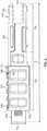
- FIG. 3shows an exploded view of the example fiber optic connector arrangement 108 of FIG. 1 .
- the example fiber optic connector arrangement 108includes a fiber optic connector 110 having a body 111 and a spring-biased ferrule 510.
- a metal reinforcing sleeve 131mounts over a rear portion 115 of the connector body 111.
- the metal reinforcing sleeve 131includes a main sleeve body 132 and a lip 133 that projects radially outwardly from the main sleeve body 132.
- the lip 133has a rearwardly facing surface 133a ( FIG. 15 ).
- An outermost sleeve 134mounts over the metal reinforcing sleeve 131.
- the outermost sleeve 134includes an internal shoulder having a forwardly facing surface 134a ( FIG. 15 ) that abuts the rearwardly facing surface 133a of the lip 133 to limit rearward movement of the reinforcing sleeve 131 relative to the outermost sleeve 134 (see FIG. 15 ).
- the outermost sleeve 134defines keying features 135 that mate with corresponding keying features 135b of the connector body 111 to ensure proper rotational alignment before the parts when the parts are assembled together.
- the connector body 111 and the outermost sleeve 134have a molded plastic construction.
- An external seal(e.g., an O-ring) 139 mounts about the outermost sleeve 134 (see FIGS. 8, 9 , and 12 ).
- the seal 139provides protection against water, dust, or other contaminants when the hardened connector arrangement 108 is mated with another component.
- a front end piece 130mounts at the front end 112 of the connector body 111 and connects to the outermost sleeve 134 such that the outermost sleeve 134 and the front end piece 130 are secured in place relative to the connector body 111 (i.e., the connector body 111 is captured between the pieces).
- the front end piece 130snap-fits to the outermost sleeve 134.
- the front end piece 130otherwise couples to the outermost sleeve 134.
- Keying features 135c of the front end piece 130may align with keying features 135a of the outermost sleeve 134 to ensure rotational alignment thereinbetween.
- the front end piece 130defines a through-opening through which a ferrule 510 of the connector 110 passes.
- a shrink tube 140(e.g., a shrink fit tube having a heat recoverable layer surrounding an adhesive layer as disclosed in U.S. Patent No. 5,470,622 ) and a strain-relief boot 143 protect the optical fibers 106 of the cable 105 as the cable exits the connector arrangement 108.
- the shrink tube 140has a forward section 141 that is configured to adherently attach over a rearward section 136 of the outmost sleeve 134 and a rearward section 142 that is configured to adherently attach over the cable 105 when installed.
- the tube 140mechanically couples the cable jacket to the sleeve 134 and seals the interface between the cable 105 and the sleeve 134.
- the tube 140mechanically couples the cable jacket to the sleeve 134 and seals the interface between the cable 105 and the sleeve 134.
- the strain-relief boot 143mounts coaxially over the shrink tube 140.
- the boot 143 and tube 140are shaped and configured to receive the transverse cross-sectional profile of the cable 105 (see FIG. 14 ).
- a fastener 145mounts over the outermost sleeve 134 for securing the fiber optic connector 110 to a component.
- the fastener 145includes a threaded nut.
- the fastener 145secures the connector 110 to another fiber optic connector (e.g., a hardened fiber optic connector).
- the fastener 145secures the connector 110 to the fiber optic adapter 150.
- outer threaded region 146 of the fastener 145may screw into inner threads of adapter 150.
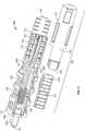
- FIGS. 4 - 6show one example implementation of a fiber optic connector 110 suitable for terminating a multi-fiber cable, such as cable 105 shown in FIG. 2 .
- the fiber optic connector 110includes a connector body 111, a multi-fiber ferrule 510 that mounts at a front end 112 of the connector body 111, and a cover 128.
- the connector body 111has a length L ( FIG. 4 ) that extends along an axis of the connector body 111.
- a fiber strain relief boot 508( FIG. 7 ) mounts at a back side of the ferrule 510.
- the connector body 111includes front and rear ends 112, 113 separated by the length L of the connector body 111.
- the connector body 111has a forward section 114 and a rearward section 115.
- the forward portion 114defines an interior 116 in which a rear portion of the multi-fiber ferrule 510 is disposed.
- a springe.g., a coil spring
- the spring 129biases the multi-fiber ferrule 510 in a forward direction through the first end 112 of the connector body 111.
- the rearward portion 115defines at least one strength component chamber 117 (see FIG. 5 ) and a fiber passage 118.
- the rearward portion 115defines two strength component chambers 117 (e.g., grooves, slots, receptacles).
- the fiber passage 118passes in between the strength component chambers 117.
- the inner walls 500 of the connector body 111taper inwardly from the forward interior 116 to the fiber passage 118 to accommodate the strength component chambers 117 (see FIG. 5 ).
- two fingers 119extend rearwardly from a rear plate 113 of the connector body 111. Each finger 119 includes inwardly directed teeth adapted to grip/bite into the cable jacket 107 when the cable 105 is attached to the connector 110.
- the multi-fiber ferrule 510is configured to receive polished ends of multiple optical fiber portions 102 (see FIG. 6 ).
- the multi-fiber ferrule 510defines a major axis A3 and a minor axis A4 ( FIGS. 4 and 5 ).
- the major and minor axes A3, A4 of the multi-fiber ferrule 510are generally perpendicular relative to one another.
- the major axis A3 of the multi-fiber ferrule 510is generally perpendicular to the major axis A1 of the jacket 107 of the fiber optic cable 105 and the minor axis A4 of the multi-fiber ferrule is generally perpendicular to the minor axis A2 of the jacket 107 of the fiber optic cable 105 (see FIG. 13 ).
- the multi-fiber ferrule 510has a width W and a height H ( FIG. 6 ).
- the multi-fiber ferrule 510supports ends of a plurality of optical fiber portions 102 in openings 101 aligned along a line (e.g., axis A3) that extends along the width of the multi-fiber ferrule 510.
- the optical fiber portions 102extend at least partially through the connector body 111.
- the optical fiber portions 102are integral with the optical fibers 106 of the fiber optic cable 105.
- the fibers 106 of the fiber optic cable 105extend through the fiber passage 118 of the connector body 111 and through the forward interior 116 of the connector body 111.
- the multi-fiber ferrule 510is mounted directly on the optical fibers 106 of the fiber optic cable 105 without any intermediate splice.
- the optical fibers 106 within the fiber optic cable 105are ribbonized or loose.
- the fiber passage 118is elongated along the minor axis A2 of the fiber optic cable 105 and ribbonized optical fibers are routed therethrough with the major axis of the ribbon aligned with a major axis of the fiber passage 118 (see FIG. 13 ).
- the matrix material binding the fibers in a rowis not visible.
- matrix material 502is schematically shown bonding the fibers 106 together to form the ribbon.
- the optical fiber portions 102are spliced to the optical fibers 106 of the fiber optic cable 105 at a splice location 103 within the connector body 111.
- the optical fiber portions 102are fusion spliced to the optical fibers 106 of the fiber optic cable 105, and the splices are mechanically reinforced using a re-coat process.
- the optical fiber portions 102are ribbonized. Ribbonized fibers 106 of the fiber optic cable 105 extend at least partially through the passage 118 towards the connector interior 116. The ribbonized fiber portions 102 are spliced to the ribbonized fibers 106 at the splice location 103.
- the fibers 106 and fiber portions 102may be fusion spliced.
- the splice location 103is reinforced and protected by a re-coating layer of additional binder or matrix material applied around the splice location 103.
- additional splice protectionis used to protect the re-coated splice section.
- a thin plate 430is disposed adjacent the ribbon and a heat shrink tube is wrapped and shrunk around the ribbon and the plate.
- the plate 430is formed of stainless steel, but may be formed from any desired material (e.g., tempered steel) in other implementations.
- the additional protectionenhances the robustness of the splice section while maintaining a low profile.
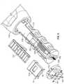
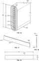
- FIG. 16shows an enlarged view of a section of an example optical cable 400 having a plurality of optical fibers 410 formed in a ribbon.
- a plate 430is disposed at the ribbon to extend across each of the fibers 410 and along part of the length of the fibers 410.
- a heat shrink tube 420is wrapped around both the optical fibers 410 and the plate 430.
- the plate 430includes a generally planar (i.e., flat) plate.
- the plate 430is generally rectangular.
- the plate 430has no flanges extending outwardly from a rectangular perimeter of the plate 430.
- the plate 430is generally flexible.
- the plate 430includes no edge reinforcements or stiffening elements. In certain implementations, the plate 430 has uniform flexibility. In some implementations, the plate 430 has a constant transverse cross-section (see FIG. 18 ) extending from one end 431 of the plate 430 to an opposite end 432 of the plate 430. In one example implementation, the plate 430 has a rectangular transverse cross-section (see FIG. 18 )
- the plate 430has a thickness PT that is no greater than about 0,0254 cm (0.01 inches) along the length PL of the plate 430. In certain implementations, the plate 430 has a thickness PT that is no greater than about 0,0127 cm (0.005 inches) along the length PL of the plate 430. In one example implementation, the plate 430 has a constant thickness PT ( FIG. 18 ) of about 0,00508 cm (0.002) inches. In other implementations, however, the plate 430 may have any desired thickness. In one example implementation, the plate 430 has a height PH ( FIG. 19 ) that is slightly greater than a height RH ( FIG. 16 ) of the recoated ribbon (see FIG.
- the plate 430has a length PL ( FIG. 19 ) that is slightly greater than a length of the re-coated ribbon, but in other implementations may have the same length or a smaller length.
- the plate 430has a height PH that is no greater than about 0,381 cm (0.15 inches) and a length PL that is no greater than about 0,3048 cm (1.2 inches).
- the plate 430has a height PH that is no greater than about 0,3302 cm (0.13 inches) and a length PL that is no greater than about 2,54 cm (1 inch).
- the plate 430has a height PH of about 0,3048 cm (0.12 inches) and a length PL of about 2,3495 cm (0.925 inches).
- the connector body 111also defines a side opening 120 ( FIG. 5 ) that extends along at least part of the length L of the connector body 111.
- the side opening 120is arranged and configured to allow the multi-fiber ferrule 510 to be inserted laterally into the connector body 111 through the side opening 120.
- the side opening 120is arranged and configured to allow the multi-fiber ferrule 510 and the optical fiber portions 102 to be inserted laterally into the connector body 111 through the side opening 120.
- the side opening 120is arranged and configured to allow the multi-fiber ferrule 510, the optical fiber portions 102, and the optical fibers 106 to be inserted laterally into the connector body 111 through the side opening 120. In this way, the optical fibers need not be axially threaded through an opening during the loading process.
- the cover 128mounts over the side opening 120 after the multi-fiber ferrule 510 has been inserted into the connector body 111 through the side opening 120.
- the side opening 120extends along the length L of the connector body 111 for at least fifty percent of the length L of the connector body 111.
- the side opening 120extends along the length L of the connector body 111 for at least 75 percent of the length L of the connector body 111.
- the lateral accessis provided along the length L of the connector body 111 from directly behind a front end plate 506 at the front end 112 to the rear end 113 of the connector body 111.
- the cover 128includes a first cover section 121 and a second cover section 125.
- the first cover section 121defines a retention surface 124 that is sized and shaped to be covered by a retaining surface 126 of the second cover section 125.
- the first cover section 121is disposed over a front portion of the side opening 120 and the second cover section 121 is disposed over a rear portion of the side opening 120.
- the cover 128is an integral piece.
- the cover 128cooperates with the connector body 111 to define one or more of the strength component chambers 117.
- the cover 128cooperates with the connector body 111 to define two strength component chambers 117 as will be described in more detail herein.
- the cover 128includes a spring compression member 122 that axially compresses the spring 129 within the connector body 111 when the cover 128 is mounted to the connector body 111.
- the spring compression member 122extends inwardly from the first cover section 121.
- the spring compression member 122includes an arm 122 that is sized and configured to extend laterally across the connector interior 116 when the cover 128 is coupled to the connector body 111.
- the spring compression member 122includes two arms 122 ( FIG. 3 ) extending laterally from the first cover section 121.
- the arms 122are sized to extend laterally across the connector interior 116 from the cover 128 to a radially opposite side of the connector body 111.
- the arm 122includes a distal tip 123 ( FIGS. 11 and 12 ) that fits into a slot or recess defined in the radially opposite side of the connector body 111.
- FIG. 6is a perspective view of the connector 110 with the first cover section 121 exploded from the body 111 to reveal part of the forward interior 116.
- a front end piece 130is exploded forwardly of the front end of the connector body 111 to reveal the opening through the front end plate 112.
- Optical fiber portions 102extend through the opening.
- the multi-fiber ferrule 510also has been exploded from the connector body 111 and rotated 90° for ease in comparing the ferrule 510 to the connector body 111.
- the side opening 120 in the connector body 111has a maximum cross-dimension CD that is smaller than a width W of the multi-fiber ferrule 510. When assembled, the ferrule 510 is oriented so that the width W extends along a major axis (e.g., see axis A3) of the front end piece 130.
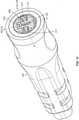
- FIGS. 7-9show the multi-fiber ferrule 510 extending through the through-opening in the front end plate 506 of the connector body 111.
- the through-openinghas a generally rectangular shape having opposing major sides and opposing minor sides.
- the ferrule 510defines rear shoulders 510a ( FIG. 8 ) that are sized and shaped to abut interior shoulders S at the minor sides of the front plate 506 to inhibit removal of the ferrule 510 from the body 111 (see FIG. 8 ).
- the ferrule 510is installed in the connector body 111 by sliding the ferrule 510 laterally through the side opening 120 of the connector body 111 and sliding the ferrule 510 forwardly through the through-opening in the front plate 506.
- the through-opening in the front plate 506is defined by one or more tapered walls T (see FIGS. 8 and 9 ). Such tapering may facilitate installation of the ferrule 510 in the connector body 111.
- the through-openinghas a transverse cross-sectional area that increases as the through-opening extends along the axis of the connector body 111 in a forward direction.
- the major sides of the through-openingdiverge from one another as the major sides extend in a forward direction.
- the minor sides of the through-openingalso diverge from one another as the major sides extend in a forward direction.
- the major and minor sidesare planar and are angled at oblique angles relative to the axis of the connector body 111.
- the rear section 115 of the connector body 111is configured to receive and retain at least one strength component 108' of a fiber optic cable 105. In certain implementations, the rear end 115 of the connector body 111 is configured to receive and retain at least two strength components 108' of the fiber optic cable105. Strength components 108' of the fiber optic cable 105 are anchored relative to the fiber optic connector 111.
- the rear section 115 of the connector body 111defines one or more chambers 117 in which the strength components 108' may be disposed.
- adhesivemay be applied to retain the strength components 108' in the chambers 117.
- the chambers 117may include inwardly directed teeth or other retention structures to aid in anchoring the strength components 108 within the chambers 117.
- the connector body 111forms a first portion of each component chamber 117 and the cover 128 (e.g., the second portion 125 of the cover 128) forms a second portion 127 of each component chamber 117 (see FIGS. 10 and 11 ).
- the cover 128is removed to reveal the side opening 120.
- the fiber portions 102are disposed in the ferrule 510. If necessary, the fiber portions 102 are spliced to exposed ends of the cable fibers 106.
- the connector body 111is installed on the cable 105 (e.g., over the splice location 103) by sliding the cable 105 through the side opening 120 so that the cable fibers 106 slide into fiber passage 118 and strength components 108' slide into the first portions of the component chambers 117.
- the cover 128is mounted to the connector body 111 to close the side opening 120 and to close the chambers 117.
- the arms 122 of the cover 128compress the spring 129 when the cover 128 is mounted to the connector body 111.
- Adhesivemay be added to the chambers 117 during the installation process.
Landscapes
- Physics & Mathematics (AREA)
- General Physics & Mathematics (AREA)
- Optics & Photonics (AREA)
- Mechanical Coupling Of Light Guides (AREA)
- Engineering & Computer Science (AREA)
- Plasma & Fusion (AREA)
Description
- The present disclosure relates generally to a fiber optic connector arrangement.
- Fiber optic communication systems are becoming prevalent in part because service providers want to deliver high bandwidth communication capabilities (e.g., data and voice) to customers. Fiber optic communication systems employ a network of fiber optic cables to transmit large volumes of data and voice signals over relatively long distances. Optical fiber connectors are an important part of most fiber optic communication systems. Fiber optic connectors allow two optical fibers to be quickly optically connected without requiring a splice. Fiber optic connectors can be used to optically interconnect two lengths of optical fiber. Fiber optic connectors can also be used to interconnect lengths of optical fiber to passive and active equipment.
- A typical fiber optic connector includes a ferrule assembly supported at a distal end of a connector housing. A spring is used to bias the ferrule assembly in a distal direction relative to the connector housing. The ferrule functions to support an end portion of at least one optical fiber (in the case of a multi-fiber ferrule, the ends of multiple fibers are supported). The ferrule has a distal end face at which a polished end of the optical fiber is located. When two fiber optic connectors are interconnected, the distal end faces of the ferrules abut one another and the ferrules are forced proximally relative to their respective connector housings against the bias of their respective springs. With the fiber optic connectors connected, their respected optical fibers are coaxially aligned such that the end faces of the optical fibers directly oppose one another. In this way, an optical signal can be transmitted from optical fiber to optical fiber through the aligned end faces of the optical fibers. For many fiber optic connector styles, alignment between two fiber optic connectors is provided through the use of an intermediate fiber optic adapter.
- A number of fiber optic connection systems have been developed for use in outside environments. Such connection systems typically have a ruggedized/hardened construction adapted for accommodating substantial pull-out forces. Such connection systems are also typically sealed to limit moisture intrusion. Example fiber optic connection systems adapted for outside use are disclosed in
U.S. Patent Nos. 6648520 ,7,264,402 ,7572065 ,7744288 ,7762726 ,7744286 ,7942590 . US 2011/0280525 A1 discloses implementation techniques for splicing together at least two optical fibers of at least two cable segments in particular for splicing together two different types of fiber optic cable segments. Each cable segment includes at least one optical fiber. A second end of the second cable segment is terminated at a fiber optic connector arrangement, e.g. a multifiber connector. Splicing the second cable segment to the first cable segment optically couples together the optical fibers of the cable segments at a splice location. The fused optical fibers at the splice location are protected within a splice enclosure arrangement.US 6,173,097 B1 discloses a multifiber connector which includes a multifile ferrule, splice components and a crimp tube that define a lengthwise extending passageway having a lateral cross-sectional shape that is generally oval for receiving and maintaining a plurality of optical fibers in a lateral side-by-side relationship. The crimp tube therefore provides the optical fibers to the splice components in an aligned and properly spaced manner.- Multi-fiber connectors can include splice-on configurations and direct termination configurations. For a splice-on configuration, optical fibers are pre-terminated within a multi-fiber ferrule and the end face of the ferrule is processed (e.g., polished and shaped as needed). After processing of the ferrule, the optical fibers have polished end faces at a front of the ferrule and also have pigtails that project rearwardly from the ferrule. In use, the multi-fiber ferrule is loaded into a connector and the pigtails are spliced to optical fibers corresponding to a fiber optic cable desired to be coupled to the connector. Typically, the splice location is positioned rearward of the connector (e.g., see
U.S. patent application serial No. 13/106,371, filed May 12, 2011 61/421,314, filed December 9, 2010 - The invention is defined by a fiber optic connector arrangement with the features of claims 1.
FIG. 1 is a perspective view of a first example hardened multi-fiber cable assembly in accordance with the principles of the present disclosure, and adapter is shown coupling the first cable assembly to a second example cable assembly terminated by a multi-fiber connector;FIG. 2 is a cross-sectional view of an example fiber optic cable having a major axis and a minor axis;FIG. 3 is an exploded view of the components of the first and second cable assemblies shown inFIG. 1 ;FIG. 4 is a top plan view of an example connector including a connector body, a spring-biased multi-fiber ferrule, and a cover;FIG. 5 is a perspective view of the example connector ofFIG. 4 shows in the cover exploded from a side opening in the connector body;FIG. 6 is a perspective view of a portion of the example hardened connector arrangement ofFIG. 3 including the connector ofFIG. 4 with a portion of the cover exploded to reveal part of the interior of the connector body, a front end piece exploded forwardly of the connector body to reveal optical fiber portions, and the multi-fiber ferrule exploded outwardly and rotated 90°;FIG. 7 is an axial cross-sectional view of the connector ofFIG. 4 ;FIG. 8 is an enlarged view of a cross-section of the example hardened connector arrangement ofFIG. 1 showing the ferrule extending outwardly through the connector body;FIG. 9 shows the view of the example hardened connector arrangement ofFIG. 8 rotated 90°;FIG. 10 is a bottom plan view of the example hardened connector arrangement ofFIG. 3 with various components exploded outwardly including the connector body, the cover, and the strain-relief boot;FIG. 11 is an axial cross-sectional view of the example hardened connector arrangement shown inFIG. 10 ;FIG. 12 is an enlarged, cross-sectional view of the example hardened connector arrangement ofFIG. 3 shown assembled and with a rear portion of the cable fibers and the strength components removed from view;FIG. 13 is a perspective view of a lateral cross-section of the example hardened connector arrangement ofFIG. 1 taken along the 13-13 line ofFIG. 1 ;FIG. 13A is a front elevational view of ribbonized fibers recoated in a matrix material;FIG. 14 is a perspective view of a lateral cross-section of the example hardened connector arrangement ofFIG. 1 taken along the 14-14 line ofFIG. 1 ;FIG. 15 is an axial cross-sectional view of the example hardened connector arrangement ofFIG. 3 shown assembled and with a rear portion of the cable fibers and the strength components removed from view;FIG. 16 is a perspective view of an enlarged section of an exampleoptical cable 400, which has a plurality ofoptical fibers 410 formed in a ribbon and a protection plate, suitable for use in the of fiber optic cable assemblies disclosed herein; andFIGS. 17-19 are various views of an example protection plate suitable for use in the cable shown inFIG. 16 .- Some aspects of this disclosure not part of the claimed invention are directed to certain types of fiber
optic cable assemblies 100 including a fiberoptic cable 105 terminated by a fiber optic connector 110 (FIG. 3 ). In accordance with some aspects, the fiberoptic connector 110 may be part of a hardened (i.e., environmentally sealed) fiberoptic connector arrangement 108. In some implementations, the fiberoptic connector arrangement 108 is configured to interface with a second fiberoptic cable assembly 200. In the example shown, the second fiberoptic cable assembly 200 includes amulti-fiber connector 210 terminating a second fiberoptic cable 205. - In other implementations, the fiber
optic connector arrangement 108 is configured to couple to a fiberoptic adapter 150 to enable connection to the fiberoptic connector 210 of the second fiberoptic cable assembly 200. For example, inFIG. 1 , theexample adapter 150 enables a first fiberoptic connector 110, which terminates a firstoptical cable 105, to mate with a secondoptic connector 210, which terminates a secondoptical cable 205. Theadapter 150 defines a socket configured to receive a connectorized end of thesecond cable assembly 200. In some implementations, thefiber optic adapter 150 is configured to mount within an opening defined in a wall, plate, enclosure, or other structure. - The fiber
optic connector arrangement 108 is a hardened (i.e., environmentally sealed) fiberoptic connector arrangement 108. In some implementations, theadapter 150 is a hardened (i.e., environmentally sealed) adapter. In certain implementations, theadapter 150 enables the hardened fiberoptic connector arrangement 108 to mate with a non-hardened (i.e., unsealed)fiber optic connector 210. For example, inFIG. 1 , theadapter 150 coupled to the hardened fiberoptic connector arrangement 108 is configured to receive a non-hardened fiber optic connector 210 (e.g., an MPO connector). Certain types of hardened fiberoptic connector arrangements 108 are configured to mate with other hardened fiber optic connector arrangements (e.g., in a plug and receptacle style connection). FIG. 2 shows one examplefiber optic cable 105 including one or moreoptical fibers 106 surrounded by anouter jacket 107. Theouter jacket 107 has an elongated transverse cross-sectional profile defining a major axis A1 and a minor axis A2. In the example shown, the transverse cross-sectional profile defined by theouter jacket 107 is generally rectangular with rounded ends. The major axis A1 and the minor axis A2 intersect perpendicularly at a lengthwise axis of thecable 105. The transverse cross-sectional profile has maximum width that extends along the major axis A1 and a maximum thickness that extends along the minor axis A2. The maximum width of the transverse cross-sectional profile is longer than the maximum thickness of the transverse cross-sectional profile. In one example implementation, thefiber optic cable 105 is a flat drop cable.- In some implementations, the first and second
optical cables fiber optic connectors optical cables outer jacket 107 also defines afirst passage 109 that extends through theouter jacket 107 along a lengthwise axis of theouter jacket 107. In certain implementations, theoptical fibers 106 are disposed loose in thefirst passage 109. In other implementations, theoptical fibers 106 may be ribbonized, buffered, or otherwise contained within thepassage 109. In the example shown, thefiber optic cable 105 includes twelveoptical fibers 106. In other implementations, however, thefiber optic cable 105 may include a greater or lesser number of optical fibers 106 (e.g., one fiber, two fibers, six fibers, ten fibers, fifteen fibers, twenty-four fibers, etc.). - At least one strength component 108' also extends through the
outer jacket 107 along a lengthwise axis of theouter jacket 107. In the example shown, first and second strength members 108' are disposed on opposite sides of thefirst passage 109 along the major axis A1. In other implementations, examplefiber optic cables 105 may include a single strength component 108'. In still other implementations, examplefiber optic cables 105 may include additional strength components 108'. In certain embodiments, each strength components 108' is formed by a layer of reinforcing elements (e.g., fibers or yarns such as aramid fibers or yarns) embedded or otherwise integrated within a binder to form a reinforcing structure. In still other embodiments, each strength component 108' can have a glass reinforced polymer (GRP) construction. In some implementations, the strength component 108' has a round cross-sectional profile. In other implementations, the cross-sectional profile of the strength component 108' may be any desired shape (e.g., rectangular, oblong, obround, etc.). Other example cable configurations are disclosed inU.S. Patent No. 8,041,166 . FIG. 3 shows an exploded view of the example fiberoptic connector arrangement 108 ofFIG. 1 . The example fiberoptic connector arrangement 108 includes afiber optic connector 110 having abody 111 and a spring-biasedferrule 510. Ametal reinforcing sleeve 131 mounts over arear portion 115 of theconnector body 111. Themetal reinforcing sleeve 131 includes amain sleeve body 132 and alip 133 that projects radially outwardly from themain sleeve body 132. Thelip 133 has a rearwardly facingsurface 133a (FIG. 15 ).- An
outermost sleeve 134 mounts over themetal reinforcing sleeve 131. Theoutermost sleeve 134 includes an internal shoulder having a forwardly facingsurface 134a (FIG. 15 ) that abuts therearwardly facing surface 133a of thelip 133 to limit rearward movement of the reinforcingsleeve 131 relative to the outermost sleeve 134 (seeFIG. 15 ). In certain implementations, theoutermost sleeve 134 defines keyingfeatures 135 that mate with corresponding keying features 135b of theconnector body 111 to ensure proper rotational alignment before the parts when the parts are assembled together. Theconnector body 111 and theoutermost sleeve 134 have a molded plastic construction. An external seal (e.g., an O-ring) 139 mounts about the outermost sleeve 134 (seeFIGS. 8, 9 , and12 ). Theseal 139 provides protection against water, dust, or other contaminants when thehardened connector arrangement 108 is mated with another component. - A
front end piece 130 mounts at thefront end 112 of theconnector body 111 and connects to theoutermost sleeve 134 such that theoutermost sleeve 134 and thefront end piece 130 are secured in place relative to the connector body 111 (i.e., theconnector body 111 is captured between the pieces). In certain implementations, thefront end piece 130 snap-fits to theoutermost sleeve 134. In other implementations, thefront end piece 130 otherwise couples to theoutermost sleeve 134. Keying features 135c of thefront end piece 130 may align with keying features 135a of theoutermost sleeve 134 to ensure rotational alignment thereinbetween. Thefront end piece 130 defines a through-opening through which aferrule 510 of theconnector 110 passes. - A shrink tube 140 (e.g., a shrink fit tube having a heat recoverable layer surrounding an adhesive layer as disclosed in
U.S. Patent No. 5,470,622 ) and a strain-relief boot 143 protect theoptical fibers 106 of thecable 105 as the cable exits theconnector arrangement 108. Theshrink tube 140 has aforward section 141 that is configured to adherently attach over arearward section 136 of theoutmost sleeve 134 and arearward section 142 that is configured to adherently attach over thecable 105 when installed. Thetube 140 mechanically couples the cable jacket to thesleeve 134 and seals the interface between thecable 105 and thesleeve 134. Thetube 140 mechanically couples the cable jacket to thesleeve 134 and seals the interface between thecable 105 and thesleeve 134. The strain-relief boot 143 mounts coaxially over theshrink tube 140. Theboot 143 andtube 140 are shaped and configured to receive the transverse cross-sectional profile of the cable 105 (seeFIG. 14 ). - A
fastener 145 mounts over theoutermost sleeve 134 for securing thefiber optic connector 110 to a component. In certain implementations, thefastener 145 includes a threaded nut. In some implementations, thefastener 145 secures theconnector 110 to another fiber optic connector (e.g., a hardened fiber optic connector). In other implementations, thefastener 145 secures theconnector 110 to thefiber optic adapter 150. For example, outer threadedregion 146 of thefastener 145 may screw into inner threads ofadapter 150. FIGS. 4 - 6 show one example implementation of afiber optic connector 110 suitable for terminating a multi-fiber cable, such ascable 105 shown inFIG. 2 . Thefiber optic connector 110 includes aconnector body 111, amulti-fiber ferrule 510 that mounts at afront end 112 of theconnector body 111, and acover 128. Theconnector body 111 has a length L (FIG. 4 ) that extends along an axis of theconnector body 111. A fiber strain relief boot 508 (FIG. 7 ) mounts at a back side of theferrule 510. Theconnector body 111 includes front andrear ends connector body 111. Theconnector body 111 has aforward section 114 and arearward section 115. Theforward portion 114 defines an interior 116 in which a rear portion of themulti-fiber ferrule 510 is disposed. A spring (e.g., a coil spring) 129 also is disposed in theconnector interior 116. Thespring 129 biases themulti-fiber ferrule 510 in a forward direction through thefirst end 112 of theconnector body 111.- The
rearward portion 115 defines at least one strength component chamber 117 (seeFIG. 5 ) and afiber passage 118. In certain implementations, therearward portion 115 defines two strength component chambers 117 (e.g., grooves, slots, receptacles). In such implementations, thefiber passage 118 passes in between thestrength component chambers 117. In certain implementations, theinner walls 500 of theconnector body 111 taper inwardly from theforward interior 116 to thefiber passage 118 to accommodate the strength component chambers 117 (seeFIG. 5 ). In certain implementations, twofingers 119 extend rearwardly from arear plate 113 of theconnector body 111. Eachfinger 119 includes inwardly directed teeth adapted to grip/bite into thecable jacket 107 when thecable 105 is attached to theconnector 110. - The
multi-fiber ferrule 510 is configured to receive polished ends of multiple optical fiber portions 102 (seeFIG. 6 ). Themulti-fiber ferrule 510 defines a major axis A3 and a minor axis A4 (FIGS. 4 and5 ). The major and minor axes A3, A4 of themulti-fiber ferrule 510 are generally perpendicular relative to one another. The major axis A3 of themulti-fiber ferrule 510 is generally perpendicular to the major axis A1 of thejacket 107 of thefiber optic cable 105 and the minor axis A4 of the multi-fiber ferrule is generally perpendicular to the minor axis A2 of thejacket 107 of the fiber optic cable 105 (seeFIG. 13 ). Themulti-fiber ferrule 510 has a width W and a height H (FIG. 6 ). Themulti-fiber ferrule 510 supports ends of a plurality ofoptical fiber portions 102 inopenings 101 aligned along a line (e.g., axis A3) that extends along the width of themulti-fiber ferrule 510. - When the
connector 110 is fully assembled, theoptical fiber portions 102 extend at least partially through theconnector body 111. In some implementations, theoptical fiber portions 102 are integral with theoptical fibers 106 of thefiber optic cable 105. In such implementations, thefibers 106 of thefiber optic cable 105 extend through thefiber passage 118 of theconnector body 111 and through theforward interior 116 of theconnector body 111. Themulti-fiber ferrule 510 is mounted directly on theoptical fibers 106 of thefiber optic cable 105 without any intermediate splice. In certain implementations, theoptical fibers 106 within thefiber optic cable 105 are ribbonized or loose. In some implementations, thefiber passage 118 is elongated along the minor axis A2 of thefiber optic cable 105 and ribbonized optical fibers are routed therethrough with the major axis of the ribbon aligned with a major axis of the fiber passage 118 (seeFIG. 13 ). InFIG. 13 , the matrix material binding the fibers in a row is not visible. InFIG. 13A ,matrix material 502 is schematically shown bonding thefibers 106 together to form the ribbon. - In other implementations, the
optical fiber portions 102 are spliced to theoptical fibers 106 of thefiber optic cable 105 at asplice location 103 within theconnector body 111. In certain implementations, theoptical fiber portions 102 are fusion spliced to theoptical fibers 106 of thefiber optic cable 105, and the splices are mechanically reinforced using a re-coat process. In certain implementations, theoptical fiber portions 102 are ribbonized.Ribbonized fibers 106 of thefiber optic cable 105 extend at least partially through thepassage 118 towards theconnector interior 116. Theribbonized fiber portions 102 are spliced to theribbonized fibers 106 at thesplice location 103. For example, thefibers 106 andfiber portions 102 may be fusion spliced. In certain implementations, thesplice location 103 is reinforced and protected by a re-coating layer of additional binder or matrix material applied around thesplice location 103. - According to the invention, additional splice protection is used to protect the re-coated splice section. A
thin plate 430 is disposed adjacent the ribbon and a heat shrink tube is wrapped and shrunk around the ribbon and the plate. In one example implementation, theplate 430 is formed of stainless steel, but may be formed from any desired material (e.g., tempered steel) in other implementations. The additional protection enhances the robustness of the splice section while maintaining a low profile. - For example,
FIG. 16 shows an enlarged view of a section of an exampleoptical cable 400 having a plurality ofoptical fibers 410 formed in a ribbon. Aplate 430 is disposed at the ribbon to extend across each of thefibers 410 and along part of the length of thefibers 410. Aheat shrink tube 420 is wrapped around both theoptical fibers 410 and theplate 430. As shown inFIG. 17 , theplate 430 includes a generally planar (i.e., flat) plate. In some implementations, theplate 430 is generally rectangular. In certain implementations, theplate 430 has no flanges extending outwardly from a rectangular perimeter of theplate 430. In certain implementations, theplate 430 is generally flexible. For example, in certain implementations, theplate 430 includes no edge reinforcements or stiffening elements. In certain implementations, theplate 430 has uniform flexibility. In some implementations, theplate 430 has a constant transverse cross-section (seeFIG. 18 ) extending from oneend 431 of theplate 430 to anopposite end 432 of theplate 430. In one example implementation, theplate 430 has a rectangular transverse cross-section (seeFIG. 18 ) - In some implementations, the
plate 430 has a thickness PT that is no greater than about 0,0254 cm (0.01 inches) along the length PL of theplate 430. In certain implementations, theplate 430 has a thickness PT that is no greater than about 0,0127 cm (0.005 inches) along the length PL of theplate 430. In one example implementation, theplate 430 has a constant thickness PT (FIG. 18 ) of about 0,00508 cm (0.002) inches. In other implementations, however, theplate 430 may have any desired thickness. In one example implementation, theplate 430 has a height PH (FIG. 19 ) that is slightly greater than a height RH (FIG. 16 ) of the recoated ribbon (seeFIG. 16 ), but in other implementations may have the same height or a smaller height. In one example implementation, theplate 430 has a length PL (FIG. 19 ) that is slightly greater than a length of the re-coated ribbon, but in other implementations may have the same length or a smaller length. In certain implementations, theplate 430 has a height PH that is no greater than about 0,381 cm (0.15 inches) and a length PL that is no greater than about 0,3048 cm (1.2 inches). In certain implementations, theplate 430 has a height PH that is no greater than about 0,3302 cm (0.13 inches) and a length PL that is no greater than about 2,54 cm (1 inch). In one example implementations, theplate 430 has a height PH of about 0,3048 cm (0.12 inches) and a length PL of about 2,3495 cm (0.925 inches). - The
connector body 111 also defines a side opening 120 (FIG. 5 ) that extends along at least part of the length L of theconnector body 111. Theside opening 120 is arranged and configured to allow themulti-fiber ferrule 510 to be inserted laterally into theconnector body 111 through theside opening 120. In certain implementations, theside opening 120 is arranged and configured to allow themulti-fiber ferrule 510 and theoptical fiber portions 102 to be inserted laterally into theconnector body 111 through theside opening 120. In certain implementations, theside opening 120 is arranged and configured to allow themulti-fiber ferrule 510, theoptical fiber portions 102, and theoptical fibers 106 to be inserted laterally into theconnector body 111 through theside opening 120. In this way, the optical fibers need not be axially threaded through an opening during the loading process. - The
cover 128 mounts over theside opening 120 after themulti-fiber ferrule 510 has been inserted into theconnector body 111 through theside opening 120. In some implementations, theside opening 120 extends along the length L of theconnector body 111 for at least fifty percent of the length L of theconnector body 111. Indeed, in some implementations, theside opening 120 extends along the length L of theconnector body 111 for at least 75 percent of the length L of theconnector body 111. In the example shown, the lateral access is provided along the length L of theconnector body 111 from directly behind afront end plate 506 at thefront end 112 to therear end 113 of theconnector body 111. - In some implementations, the
cover 128 includes afirst cover section 121 and asecond cover section 125. Thefirst cover section 121 defines aretention surface 124 that is sized and shaped to be covered by a retainingsurface 126 of thesecond cover section 125. In the example shown, thefirst cover section 121 is disposed over a front portion of theside opening 120 and thesecond cover section 121 is disposed over a rear portion of theside opening 120. In other implementations, thecover 128 is an integral piece. In some implementations, thecover 128 cooperates with theconnector body 111 to define one or more of thestrength component chambers 117. In the example shown inFIG. 13 , thecover 128 cooperates with theconnector body 111 to define twostrength component chambers 117 as will be described in more detail herein. - The
cover 128 includes aspring compression member 122 that axially compresses thespring 129 within theconnector body 111 when thecover 128 is mounted to theconnector body 111. In some implementations, thespring compression member 122 extends inwardly from thefirst cover section 121. In certain implementations, thespring compression member 122 includes anarm 122 that is sized and configured to extend laterally across theconnector interior 116 when thecover 128 is coupled to theconnector body 111. In the example shown, thespring compression member 122 includes two arms 122 (FIG. 3 ) extending laterally from thefirst cover section 121. In certain implementations, thearms 122 are sized to extend laterally across theconnector interior 116 from thecover 128 to a radially opposite side of theconnector body 111. In the example shown inFIG. 7 , thearm 122 includes a distal tip 123 (FIGS. 11 and12 ) that fits into a slot or recess defined in the radially opposite side of theconnector body 111. FIG. 6 is a perspective view of theconnector 110 with thefirst cover section 121 exploded from thebody 111 to reveal part of theforward interior 116. Afront end piece 130 is exploded forwardly of the front end of theconnector body 111 to reveal the opening through thefront end plate 112.Optical fiber portions 102 extend through the opening. Themulti-fiber ferrule 510 also has been exploded from theconnector body 111 and rotated 90° for ease in comparing theferrule 510 to theconnector body 111. Theside opening 120 in theconnector body 111 has a maximum cross-dimension CD that is smaller than a width W of themulti-fiber ferrule 510. When assembled, theferrule 510 is oriented so that the width W extends along a major axis (e.g., see axis A3) of thefront end piece 130.FIGS. 7-9 show themulti-fiber ferrule 510 extending through the through-opening in thefront end plate 506 of theconnector body 111. In certain implementations, the through-opening has a generally rectangular shape having opposing major sides and opposing minor sides. Theferrule 510 definesrear shoulders 510a (FIG. 8 ) that are sized and shaped to abut interior shoulders S at the minor sides of thefront plate 506 to inhibit removal of theferrule 510 from the body 111 (seeFIG. 8 ). Theferrule 510 is installed in theconnector body 111 by sliding theferrule 510 laterally through theside opening 120 of theconnector body 111 and sliding theferrule 510 forwardly through the through-opening in thefront plate 506.- In some implementations, the through-opening in the
front plate 506 is defined by one or more tapered walls T (seeFIGS. 8 and 9 ). Such tapering may facilitate installation of theferrule 510 in theconnector body 111. In certain implementations, the through-opening has a transverse cross-sectional area that increases as the through-opening extends along the axis of theconnector body 111 in a forward direction. In certain implementations, the major sides of the through-opening diverge from one another as the major sides extend in a forward direction. In certain implementations, the minor sides of the through-opening also diverge from one another as the major sides extend in a forward direction. In certain implementations, the major and minor sides are planar and are angled at oblique angles relative to the axis of theconnector body 111. - In some implementations, the
rear section 115 of theconnector body 111 is configured to receive and retain at least one strength component 108' of afiber optic cable 105. In certain implementations, therear end 115 of theconnector body 111 is configured to receive and retain at least two strength components 108' of the fiber optic cable105. Strength components 108' of thefiber optic cable 105 are anchored relative to thefiber optic connector 111. For example, in certain implementations, therear section 115 of theconnector body 111 defines one ormore chambers 117 in which the strength components 108' may be disposed. In certain implementations, adhesive may be applied to retain the strength components 108' in thechambers 117. In certain implementations, thechambers 117 may include inwardly directed teeth or other retention structures to aid in anchoring thestrength components 108 within thechambers 117. - In some implementations, the
connector body 111 forms a first portion of eachcomponent chamber 117 and the cover 128 (e.g., thesecond portion 125 of the cover 128) forms asecond portion 127 of each component chamber 117 (seeFIGS. 10 and 11 ). When theconnector 110 is assembled, thecover 128 is removed to reveal theside opening 120. Thefiber portions 102 are disposed in theferrule 510. If necessary, thefiber portions 102 are spliced to exposed ends of thecable fibers 106. Theconnector body 111 is installed on the cable 105 (e.g., over the splice location 103) by sliding thecable 105 through theside opening 120 so that thecable fibers 106 slide intofiber passage 118 and strength components 108' slide into the first portions of thecomponent chambers 117. Thecover 128 is mounted to theconnector body 111 to close theside opening 120 and to close thechambers 117. Thearms 122 of thecover 128 compress thespring 129 when thecover 128 is mounted to theconnector body 111. Adhesive may be added to thechambers 117 during the installation process.
Claims (7)
- A fiber optic connector arrangement (108) comprising:a multi-fiber optic connector having a splice-on configuration including multiple optical fibers (102) pre-installed in a multi-fiber ferrule (510); the fiber optic connector arrangement (108) being hardened, wherein the fiber optic connector (110) includes a connector body (111), and wherein theoptical fibers (102) are spliced to optical fibers (106, 410) of a fiberoptic cable (105) at a splice location (103) within the connector body (111),comprising a flat plate (430) at the splice location (103),characterized in that the fiber optic cable (105) is a ribbonized fiber optic cable (105) and by a shrink tube (420) wrapped and shrunk around the ribbonized fiber optic cable (105) and the flat plate (430).
- The fiber optic connector arrangement of claim 1, further comprising a metal sleeve (131) that mounts over a rear portion (115) of the connector body (111) and an outermost sleeve (134) that mounts over the metal sleeve (131), further comprising a fastener (145) being mounted over the outermost sleeve for securing the fiber optic connector (110) to a non-hardened fiber optic connector or another hardened fiber optic connector.
- The fiber optic connector arrangement of claim 2, wherein the fastener is a threaded nut.
- The fiber optic connector arrangement of claim 1, further comprising a strain-relief boot (143) to protect the optical fiber (106) of the ribbonized fiber optic cable (105) as the ribbonized fiber optic cable (105) exits the connector arrangement (108).
- The fiber optic connector arrangement of claim 1, wherein a rearward portion (115 ) of the connector body (111) defines at least one strength component chamber and a fiber passage.
- The fiber optic connector of claim 2, further comprising an external seal (139) that mounts about the outermost sleeve (134).
- The fiber optic connector of claim 2, wherein the connector body (111) and the outermost sleeve (134) have a molded plastic construction.
Priority Applications (1)
| Application Number | Priority Date | Filing Date | Title |
|---|---|---|---|
| EP22161784.8AEP4047402A1 (en) | 2011-11-23 | 2012-10-30 | Multi-fiber fiber optic connector |
Applications Claiming Priority (3)
| Application Number | Priority Date | Filing Date | Title |
|---|---|---|---|
| US201161563275P | 2011-11-23 | 2011-11-23 | |
| EP12851590.5AEP2783248B1 (en) | 2011-11-23 | 2012-10-30 | Multi-fiber fiber optic connector |
| PCT/US2012/062526WO2013077969A1 (en) | 2011-11-23 | 2012-10-30 | Multi-fiber fiber optic connector |
Related Parent Applications (1)
| Application Number | Title | Priority Date | Filing Date |
|---|---|---|---|
| EP12851590.5ADivisionEP2783248B1 (en) | 2011-11-23 | 2012-10-30 | Multi-fiber fiber optic connector |
Related Child Applications (1)
| Application Number | Title | Priority Date | Filing Date |
|---|---|---|---|
| EP22161784.8ADivisionEP4047402A1 (en) | 2011-11-23 | 2012-10-30 | Multi-fiber fiber optic connector |
Publications (2)
| Publication Number | Publication Date |
|---|---|
| EP3460550A1 EP3460550A1 (en) | 2019-03-27 |
| EP3460550B1true EP3460550B1 (en) | 2022-03-16 |
Family
ID=48470200
Family Applications (3)
| Application Number | Title | Priority Date | Filing Date |
|---|---|---|---|
| EP18197868.5AActiveEP3460550B1 (en) | 2011-11-23 | 2012-10-30 | Multi-fiber fiber optic connector |
| EP22161784.8APendingEP4047402A1 (en) | 2011-11-23 | 2012-10-30 | Multi-fiber fiber optic connector |
| EP12851590.5AActiveEP2783248B1 (en) | 2011-11-23 | 2012-10-30 | Multi-fiber fiber optic connector |
Family Applications After (2)
| Application Number | Title | Priority Date | Filing Date |
|---|---|---|---|
| EP22161784.8APendingEP4047402A1 (en) | 2011-11-23 | 2012-10-30 | Multi-fiber fiber optic connector |
| EP12851590.5AActiveEP2783248B1 (en) | 2011-11-23 | 2012-10-30 | Multi-fiber fiber optic connector |
Country Status (9)
| Country | Link |
|---|---|
| US (10) | US9304262B2 (en) |
| EP (3) | EP3460550B1 (en) |
| CN (1) | CN104011572B (en) |
| AU (3) | AU2012340980B2 (en) |
| BR (1) | BR112014012461B1 (en) |
| ES (1) | ES2703235T3 (en) |
| MX (1) | MX336679B (en) |
| RU (1) | RU2611687C2 (en) |
| WO (1) | WO2013077969A1 (en) |
Families Citing this family (85)
| Publication number | Priority date | Publication date | Assignee | Title |
|---|---|---|---|---|
| CN104011572B (en) | 2011-11-23 | 2016-03-16 | Adc电信公司 | Multi-fiber fiber optic connector |
| RU2014138122A (en) | 2012-02-20 | 2016-04-10 | Адс Телекоммьюникейшнз, Инк. | FIBER OPTICAL CONNECTOR, FIBER OPTICAL CONNECTOR AND CABLE ASSEMBLY AND METHODS FOR THEIR MANUFACTURE |
| US8939654B2 (en) | 2012-09-27 | 2015-01-27 | Adc Telecommunications, Inc. | Ruggedized multi-fiber fiber optic connector with sealed dust cap |
| CN104823090B (en) | 2012-11-30 | 2017-04-05 | 泰科电子公司 | Fiber optic connectors with field-installable outer connector housings |
| WO2014206976A1 (en) | 2013-06-27 | 2014-12-31 | Tyco Electronics Raychem Bvba | Fiber optic cable anchoring device for use with fiber optic connectors and methods of using the same |
| CN104849816B (en) | 2014-02-14 | 2017-01-11 | 泰科电子(上海)有限公司 | Optical fiber connector and assembly method therefor |
| CN104849815B (en) | 2014-02-14 | 2017-01-18 | 泰科电子(上海)有限公司 | Optical fiber connector and assembly method therefor |
| US9720185B2 (en) | 2014-05-23 | 2017-08-01 | Commscope Technologies Llc | Systems and method for processing optical cable assemblies |
| EP3158375A1 (en) | 2014-06-23 | 2017-04-26 | Tyco Electronics Raychem BVBA | Fiber optic connection system with fast coupling mechanism |
| WO2016004347A1 (en)* | 2014-07-03 | 2016-01-07 | Adc Telecommunications, Inc. | Optical fiber connector for multi-fiber cable |
| US9519114B2 (en) | 2014-07-03 | 2016-12-13 | Commscope Technologies Llc | Optical fiber connector for multi-fiber cable |
| EP3167321B1 (en) | 2014-07-07 | 2020-09-02 | Commscope Technologies LLC | Optical ferrule for multi-fiber cable and hardened multi-fiber optic connector therefore |
| CN105445862B (en) | 2014-07-09 | 2018-01-19 | 泰科电子(上海)有限公司 | The joints of optical fibre and its on-site assembly method |
| CN204359965U (en) | 2014-11-20 | 2015-05-27 | 泰科电子(上海)有限公司 | Connector system |
| CN105717576B (en) | 2014-12-04 | 2019-07-12 | 泰科电子(上海)有限公司 | System and method for protecting fibre junction head |
| WO2016095213A1 (en) | 2014-12-19 | 2016-06-23 | Tyco Electronics (Shanghai) Co., Ltd. | Hardened fiber optic connector with pre-compressed spring |
| US10560211B2 (en) | 2015-02-26 | 2020-02-11 | Commscope Technologies Llc | Cable arrangement with wavelength division multiplexer |
| JP6576052B2 (en)* | 2015-03-06 | 2019-09-18 | 株式会社フジクラ | Plug side optical connector, optical connector system, and optical cable with connector |
| JP6527718B2 (en)* | 2015-03-06 | 2019-06-05 | 株式会社フジクラ | Plug side optical connector and optical connector system |
| JP6671847B2 (en)* | 2015-03-06 | 2020-03-25 | 株式会社フジクラ | Optical connector and optical cable with connector |
| JP6576051B2 (en)* | 2015-03-06 | 2019-09-18 | 株式会社フジクラ | Optical connector, optical cable with connector, and optical connector mounting method |
| EP3822676A1 (en) | 2015-04-02 | 2021-05-19 | CommScope Technologies LLC | Fiber optic network architecture using high fiber-count fiber optic connectors |
| EP3345026B1 (en) | 2015-08-31 | 2020-10-14 | Commscope Technologies LLC | Splice-on fiber optic connector |
| US10620385B2 (en) | 2015-11-30 | 2020-04-14 | Commscope Technologies Llc | Fiber optic connector and assembly thereof |
| US10641970B2 (en) | 2015-12-16 | 2020-05-05 | Commscope Technologies Llc | Field installed fiber optic connector |
| US9739954B1 (en)* | 2016-02-19 | 2017-08-22 | Corning Optical Communications LLC | Strain relief device for a fiber optic connector |
| US10067302B2 (en) | 2016-03-24 | 2018-09-04 | Commscope Technologies Llc | Fiber optic wall jack |
| US10234641B2 (en)* | 2016-06-14 | 2019-03-19 | Clearfield, Inc. | In-line sealed adapter tube |
| WO2018044728A1 (en) | 2016-09-01 | 2018-03-08 | Commscope Technologies Llc | End face cleaning gel for hardened multi-fiber optical connectors; and methods |
| WO2018163498A1 (en)* | 2017-03-08 | 2018-09-13 | ソニー・オリンパスメディカルソリューションズ株式会社 | Medical device and method for manufacturing medical device |
| EP3602155A1 (en) | 2017-03-21 | 2020-02-05 | Corning Research & Development Corporation | Fiber optic cable assembly with thermoplastically overcoated fusion splice, and related method and apparatus |
| WO2018197410A1 (en)* | 2017-04-25 | 2018-11-01 | CommScope Connectivity Belgium BVBA | Connection module for cable seal gel block |
| MX2019014655A (en) | 2017-06-12 | 2020-02-07 | Commscope Technologies Llc | DISTRIBUTED BYPASS ARCHITECTURE THAT INCORPORATES HARD CONNECTIVITY. |
| KR102396108B1 (en) | 2017-06-22 | 2022-05-10 | 삼성전자주식회사 | Three-dimensional electrode structure and secondary battery including the same |
| US11300746B2 (en) | 2017-06-28 | 2022-04-12 | Corning Research & Development Corporation | Fiber optic port module inserts, assemblies and methods of making the same |
| US10359577B2 (en) | 2017-06-28 | 2019-07-23 | Corning Research & Development Corporation | Multiports and optical connectors with rotationally discrete locking and keying features |
| US11668890B2 (en) | 2017-06-28 | 2023-06-06 | Corning Research & Development Corporation | Multiports and other devices having optical connection ports with securing features and methods of making the same |
| CN111051945B (en) | 2017-06-28 | 2023-12-29 | 康宁研究与开发公司 | Compact fiber optic connector, cable assembly and method of making the same |
| US12271040B2 (en) | 2017-06-28 | 2025-04-08 | Corning Research & Development Corporation | Fiber optic extender ports, assemblies and methods of making the same |
| EP3704524A4 (en) | 2017-10-30 | 2021-09-15 | Commscope Technologies LLC | Universal cable anchoring for plug connectors |
| US10746938B2 (en) | 2017-11-17 | 2020-08-18 | Commscope Technologies Llc | Fiber optic connectors |
| RU2742142C1 (en) | 2017-11-22 | 2021-02-02 | Телефонактиеболагет Лм Эрикссон (Пабл) | Cable termination assembly |
| US11543597B2 (en) | 2018-01-12 | 2023-01-03 | Commscope Technologies Llc | Ferrule-less fiber optic connector with re-coat layer to protect buckling portion of optical fiber |
| CA3095881A1 (en) | 2018-04-02 | 2019-10-10 | Senko Advanced Components, Inc | Hybrid ingress protected connector and adapter assembly |
| EP3814818A4 (en)* | 2018-05-07 | 2022-02-09 | PPC Broadband, Inc. | Fiber optical connector |
| US10948664B2 (en) | 2018-05-08 | 2021-03-16 | Senko Advanced Components, Inc. | Ingress protected optical fiber connector having a reduced diameter with a removable retaining nut |
| CN112888978B (en) | 2018-09-07 | 2023-01-13 | 康宁公司 | Optical fiber fanout assembly with ribbonized interface for multi-way fusion splicing and method of making same |
| US10976492B2 (en) | 2018-09-07 | 2021-04-13 | Corning Incorporated | Cable with overcoated non-coplanar groups of fusion spliced optical fibers, and fabrication method |
| US11092756B2 (en) | 2018-10-10 | 2021-08-17 | Senko Advanced Components, Inc. | Ingress protected connector with an unitary orientation feature |
| US10976502B2 (en) | 2018-10-11 | 2021-04-13 | Seniko Advanced Components, Inc. | Outdoor rated assembly configured to blind mate opposing fiber optic connectors therein with a safety spring assembly |
| US11016247B2 (en) | 2018-10-11 | 2021-05-25 | Senko Advanced Components Inc | Mechanical splice protective sleeve for securing a splice area formed by splicing a plural of optical fibers |
| US11275221B2 (en)* | 2018-10-16 | 2022-03-15 | Senko Advanced Components, Inc. | Springless retention structure for an ingress protected hybrid connector assembly |
| PT3903136T (en) | 2018-12-28 | 2024-12-05 | Corning Res & Dev Corp | Multiport assemblies including mounting features or dust plugs |
| US11307359B2 (en) | 2019-02-07 | 2022-04-19 | Senko Advanced Components, Inc. | Ingress protected, outdoor rated connector with integrated optical connector plug frame |
| WO2020242847A1 (en) | 2019-05-31 | 2020-12-03 | Corning Research & Development Corporation | Multiports and other devices having optical connection ports with sliding actuators and methods of making the same |
| CN112099153B (en)* | 2019-06-17 | 2025-04-01 | 泰科电子(上海)有限公司 | Connector module |
| US11906795B2 (en) | 2019-06-19 | 2024-02-20 | Senko Advanced Components, Inc. | Fiber optic connector assembly with crimp tube subassembly and method of use |
| CN112241049A (en)* | 2019-07-16 | 2021-01-19 | 康普技术有限责任公司 | Optical fiber connector and optical fiber connector assembly |
| CN110542952B (en) | 2019-07-26 | 2021-05-18 | 华为技术有限公司 | Optical fiber connector and optical fiber connector |
| US11294133B2 (en) | 2019-07-31 | 2022-04-05 | Corning Research & Development Corporation | Fiber optic networks using multiports and cable assemblies with cable-to-connector orientation |
| US11360265B2 (en) | 2019-07-31 | 2022-06-14 | Corning Research & Development Corporation | Fiber optic cable assembly with overlapping bundled strength members, and fabrication method and apparatus |
| WO2021026482A1 (en) | 2019-08-08 | 2021-02-11 | Senko Advanced Components, Inc | Push pull mechanism for an outdoor rated connector assembly |
| MX2022002410A (en)* | 2019-08-26 | 2022-05-13 | Commscope Technologies Llc | FIBER OPTICAL CONNECTORS AND FIBER OPTICAL CONNECTION SYSTEMS. |
| US11487073B2 (en) | 2019-09-30 | 2022-11-01 | Corning Research & Development Corporation | Cable input devices having an integrated locking feature and assemblies using the cable input devices |
| EP3805827B1 (en) | 2019-10-07 | 2025-07-30 | Corning Research & Development Corporation | Fiber optic terminals and fiber optic networks having variable ratio couplers |
| US11650388B2 (en) | 2019-11-14 | 2023-05-16 | Corning Research & Development Corporation | Fiber optic networks having a self-supporting optical terminal and methods of installing the optical terminal |
| US11536921B2 (en) | 2020-02-11 | 2022-12-27 | Corning Research & Development Corporation | Fiber optic terminals having one or more loopback assemblies |
| EP4204876A1 (en)* | 2020-08-31 | 2023-07-05 | Corning Research & Development Corporation | Male plug optical connectors configured for mating with dissimilar connector |
| US11604320B2 (en) | 2020-09-30 | 2023-03-14 | Corning Research & Development Corporation | Connector assemblies for telecommunication enclosures |
| US11886009B2 (en) | 2020-10-01 | 2024-01-30 | Corning Research & Development Corporation | Coating fusion spliced optical fibers and subsequent processing methods thereof |
| US11754786B2 (en)* | 2020-10-29 | 2023-09-12 | Corning Research & Development Corporation | Multi-fiber splice protector and cable assembly with intra-connector splices, and fabrication method |
| AU2021368055A1 (en) | 2020-10-30 | 2023-06-08 | Corning Research & Development Corporation | Female fiber optic connectors having a rocker latch arm and methods of making the same |
| US11808983B2 (en) | 2020-11-24 | 2023-11-07 | Corning Research & Development Corporation | Multi-fiber splice protector with compact splice-on furcation housing |
| US11994722B2 (en) | 2020-11-30 | 2024-05-28 | Corning Research & Development Corporation | Fiber optic adapter assemblies including an adapter housing and a locking housing |
| US11686913B2 (en) | 2020-11-30 | 2023-06-27 | Corning Research & Development Corporation | Fiber optic cable assemblies and connector assemblies having a crimp ring and crimp body and methods of fabricating the same |
| US11927810B2 (en) | 2020-11-30 | 2024-03-12 | Corning Research & Development Corporation | Fiber optic adapter assemblies including a conversion housing and a release member |
| US11880076B2 (en) | 2020-11-30 | 2024-01-23 | Corning Research & Development Corporation | Fiber optic adapter assemblies including a conversion housing and a release housing |
| US11867947B2 (en) | 2021-04-30 | 2024-01-09 | Corning Research & Development Corporation | Cable assembly having routable splice protectors |
| DE102021111848A1 (en)* | 2021-05-06 | 2022-11-10 | Odu Gmbh & Co. Kg | Plug device, connector and connecting cable |
| US11947167B2 (en) | 2021-05-26 | 2024-04-02 | Corning Research & Development Corporation | Fiber optic terminals and tools and methods for adjusting a split ratio of a fiber optic terminal |
| CN113589459A (en)* | 2021-07-28 | 2021-11-02 | 江苏亨通光网科技有限公司 | 5.0mm round cable optical fiber assembly and manufacturing method thereof |
| USD1060249S1 (en) | 2021-08-30 | 2025-02-04 | Corning Research & Development Corporation | Multifiber connector for making optical connections |
| GB2622374A (en)* | 2022-09-13 | 2024-03-20 | Oxford Fiber Ltd | Optical fibre connector |
| US20240231014A9 (en)* | 2022-10-24 | 2024-07-11 | Baker Hughes Holdings Llc | Sealable fiber optic cable connection system |
| CN116577877A (en)* | 2023-04-18 | 2023-08-11 | 中国电信集团工会上海市委员会 | An automatic dust-proof multi-core connector and its method |
Citations (3)
| Publication number | Priority date | Publication date | Assignee | Title |
|---|---|---|---|---|
| US5832162A (en)* | 1995-12-15 | 1998-11-03 | Tii Industries, Inc. | Multiple fiber fusion splice protection sleeve |
| US6173097B1 (en)* | 1998-07-01 | 2001-01-09 | Siecor Operations, Llc | Field installable multifiber connector |
| US20110280525A1 (en)* | 2010-05-14 | 2011-11-17 | Adc Telecommunications, Inc. | Splice Enclosure Arrangement for Fiber Optic Cables |
Family Cites Families (173)
| Publication number | Priority date | Publication date | Assignee | Title |
|---|---|---|---|---|
| US2027962A (en) | 1933-03-03 | 1936-01-14 | Nat Carbon Co Inc | Production of articles from plastic compositions |
| NL130678C (en) | 1960-07-15 | 1900-01-01 | ||
| BE609815A (en) | 1960-10-31 | |||
| US3777048A (en) | 1971-09-22 | 1973-12-04 | Kaiser Aluminium Chem Corp | Molding process for splicing cable and product formed thereby |
| FR2395518A1 (en) | 1977-06-22 | 1979-01-19 | Comp Generale Electricite | CONNECTOR FOR OPTICAL FIBER |
| DE3172553D1 (en) | 1980-11-28 | 1985-11-07 | Toshiba Kk | Method for manufacturing a module for a fiber optic link |
| US4410561A (en) | 1981-07-31 | 1983-10-18 | Bell Telephone Laboratories, Incorporated | Method of forming coated optical fiber |
| JPS58120713U (en) | 1982-02-06 | 1983-08-17 | 株式会社中西歯科器械製作所 | Switch operation mechanism of light source circuit in optical air turbine handpiece |
| US4389428A (en) | 1982-03-15 | 1983-06-21 | International Telephone And Telegraph Corporation | Method of rejacketing a fusion splice in an ultraviolet light curable resin jacketed optical fiber |
| US4515434A (en) | 1983-03-09 | 1985-05-07 | Allied Corporation | Fiber optic connector |
| GB8327450D0 (en) | 1983-10-13 | 1983-11-16 | Bicc Plc | Optical fibre splicing |
| US4711752A (en) | 1984-06-22 | 1987-12-08 | Itt Corporation | Method and apparatus for molding fiber optic connector ferrule |
| US4662307A (en) | 1985-05-31 | 1987-05-05 | Corning Glass Works | Method and apparatus for recoating optical waveguide fibers |
| US4598974A (en) | 1985-08-15 | 1986-07-08 | International Business Machines Corporation | Optical fiber connector having integral electrodes for use in fusion splicing |
| US4744629A (en)* | 1985-08-16 | 1988-05-17 | Augat Inc. | Multifiber optical cable connector |
| US4798431A (en) | 1986-12-04 | 1989-01-17 | Itt Corporation | Optic fiber contact |
| NZ222903A (en) | 1986-12-17 | 1990-07-26 | Focas Ltd | Optical fibre connector: heat shrinkable sleeve |
| US4877306A (en) | 1987-09-30 | 1989-10-31 | Corning Glass Works | Coated optical waveguide fibers |
| US5046813A (en) | 1988-09-07 | 1991-09-10 | Fujikura Ltd. | Method and apparatus for aligning a plurality of single-fiber cables, and method of simultaneously fusion-splicing such cables |
| US4877303A (en) | 1988-09-22 | 1989-10-31 | Northern Telecom Limited | Fiber optic connector element & method for its use |
| US4964688A (en) | 1988-09-22 | 1990-10-23 | Northern Telecom Limited | Fiber optic connector element and method for its use |
| US4920366A (en) | 1989-05-31 | 1990-04-24 | Amp Incorporated | Construction of an optical fiber with a connector |
| US5093048A (en) | 1989-08-07 | 1992-03-03 | Grumman Aerospace Corporation | Rejacketing a spliced fiber optic cable |
| US5022735A (en) | 1989-11-07 | 1991-06-11 | The Charles Stark Draper Laboratory, Inc. | Fiber splice coating system |
| US5034170A (en) | 1989-11-07 | 1991-07-23 | Bell Communications Research, Inc. | High-precision adjustable injection molding of single-mode fiber optic connectors |
| US5127820A (en) | 1989-11-07 | 1992-07-07 | Bell Communications Research, Inc. | High-precision adjustable injection molding of single-mode fiber optic connectors |
| US5040867A (en) | 1990-03-21 | 1991-08-20 | Siecor Corporation | Slide fit optical connector having end cap to prevent rotation |
| US5042901A (en) | 1990-07-31 | 1991-08-27 | Siecor Corporation | Preconnectorized optical splice closure |
| US5470622A (en) | 1990-11-06 | 1995-11-28 | Raychem Corporation | Enclosing a substrate with a heat-recoverable article |
| CA2071344C (en) | 1991-06-18 | 1997-04-15 | Hiroshi Suganuma | Process for producing an optical fiber coupler |
| US5222171A (en) | 1991-10-21 | 1993-06-22 | Jozef Straus | Fused optical fiber splice element |
| US5210810A (en)* | 1991-12-19 | 1993-05-11 | At&T Bell Laboratories | Hermaphroditic connector for single fiber optical cable |
| CA2060424C (en) | 1992-01-31 | 1999-12-07 | Ming-Jun Li | Optical coupling element |
| US5263105A (en) | 1992-05-29 | 1993-11-16 | E. I. Du Pont De Nemours And Company | Connector assembly for connecting an optical fiber cable to a socket |
| US5367594A (en) | 1992-09-01 | 1994-11-22 | The Whitaker Corporation | Fiber optic splicer-connector |
| US5317663A (en) | 1993-05-20 | 1994-05-31 | Adc Telecommunications, Inc. | One-piece SC adapter |
| US5375183A (en) | 1993-05-25 | 1994-12-20 | The Whitaker Corporation | Overmolded alignment ferrule |
| JP3087561B2 (en) | 1993-12-28 | 2000-09-11 | 三菱電機株式会社 | Optical semiconductor module and manufacturing method thereof |
| US5740301A (en) | 1994-06-27 | 1998-04-14 | Fiberlign Division Of Preformed Line Products Ltd. | Fusion splicing block with electrodes disposed on planar surface |
| US5465313A (en) | 1994-06-29 | 1995-11-07 | Molex Incorporated | Optical fiber connector and method of fabricating same |
| US5495545A (en) | 1994-10-24 | 1996-02-27 | International Business Machines Corporation | Method for extending bandwidth of large core fiber optic transmission links |
| JPH08234042A (en) | 1995-03-01 | 1996-09-13 | Furukawa Electric Co Ltd:The | Optical fiber fusion splicer |
| DE59602092D1 (en) | 1995-03-07 | 1999-07-08 | Siemens Ag | SPLICE DEVICE FOR WELDING LIGHTWAVE GUIDES |
| JPH08262271A (en) | 1995-03-24 | 1996-10-11 | Hirose Electric Co Ltd | Dustproof cap for optical fiber connector |
| US5748819A (en) | 1995-04-05 | 1998-05-05 | Siecor Corporation | Field installable optical fiber connector and an associated method of fabrication |
| DE19517750A1 (en) | 1995-05-15 | 1996-11-21 | Siemens Ag | Optical waveguide connector for cable |
| JP3317824B2 (en) | 1995-08-25 | 2002-08-26 | 株式会社精工技研 | Manufacturing method of optical attenuation fiber assembly and optical attenuation fiber assembly |
| JP3620121B2 (en) | 1995-10-31 | 2005-02-16 | 住友電気工業株式会社 | Optical connector and assembly method |
| US5815619A (en) | 1996-12-10 | 1998-09-29 | Bloom; Cary | Fiber optic connector hermetically terminated |
| JP3515305B2 (en) | 1997-01-16 | 2004-04-05 | 株式会社フジクラ | Optical connector |
| CA2226052A1 (en) | 1997-02-13 | 1998-08-13 | Diamond Sa | Plug for an optical fiber plug connector and method of its manufacture |
| JP3602339B2 (en) | 1997-06-16 | 2004-12-15 | 株式会社フジクラ | Optical connector |
| US6247850B1 (en) | 1998-11-02 | 2001-06-19 | The Whitaker Corporation | Multiple fiber splice element and connector |
| US6068410A (en) | 1997-12-22 | 2000-05-30 | Siecor Corporation | Splice housing assembly and associated assembly method for mechanically decoupling a ferrule from a splice body |
| US6120193A (en) | 1997-12-22 | 2000-09-19 | Siecor Corporation | Splice house subassembly and associated connector |
| EP0939327A3 (en) | 1998-02-27 | 2002-02-13 | Siemens Aktiengesellschaft | Optical fibre connector and method of manufacture thereof |
| JP3792887B2 (en) | 1998-04-03 | 2006-07-05 | 三和電気工業株式会社 | Optical connector plug |
| US6498888B1 (en) | 1998-04-22 | 2002-12-24 | Institut National D'optique | High-attenuation fiber with cladding mode suppression for all-fiber optical attenuator |
| US6085003A (en) | 1998-07-28 | 2000-07-04 | Us Conec Ltd | Multifiber connector having a free floating ferrule |
| KR20010030946A (en) | 1998-08-07 | 2001-04-16 | 오카야마 노리오 | Ferrule for optical connector, mold for ferrule, method of manufacturing ferrule for optical connector, and method of testing ferrule for optical connector |
| EP1134603B1 (en) | 1998-11-26 | 2009-06-17 | SMK Corporation | Method of producing a ferrule |
| DE19933740C2 (en) | 1999-07-19 | 2003-10-30 | Ccs Technology Inc | Optical fiber connector and method for connection to the end of an optical fiber |
| US6340249B1 (en) | 1999-09-13 | 2002-01-22 | Alcoa Fujikura Limited | Connector assembly and method of securing fiber optic cable to connector |
| US6728451B2 (en)* | 1999-09-21 | 2004-04-27 | Tyco Telecommunications (Us) Inc. | Optical fiber holding structure and method of making same |
| WO2001027673A1 (en) | 1999-10-14 | 2001-04-19 | Cidra Corporation | Method and apparatus for recoating a fiber optic splice |
| JP2001215358A (en) | 2000-01-31 | 2001-08-10 | Molex Inc | Optical fiber ferrule and its manufacturing method |
| US7090406B2 (en) | 2000-05-26 | 2006-08-15 | Corning Cable Systems Llc | Preconnectorized fiber optic drop cables and assemblies |
| US7111990B2 (en)* | 2000-05-26 | 2006-09-26 | Corning Cable Systems, Llc | Figure-eight preconnectorized fiber optic drop cables and assemblies |
| US6648520B2 (en)* | 2001-09-28 | 2003-11-18 | Corning Cable Systems Llc | Fiber optic plug |
| DE50113125D1 (en) | 2000-06-05 | 2007-11-22 | Huber+Suhner Ag | METHOD FOR CONFIGURING AN OPTICAL CONNECTOR, DEVICE FOR CARRYING OUT SAID METHOD AND CONNECTOR FOR USE IN SUCH A PROCESS |
| JP2004503814A (en) | 2000-06-12 | 2004-02-05 | クローネ ゲーエムベーハー | Assembly and method for use in terminating optical fibers |
| US6439780B1 (en) | 2000-08-31 | 2002-08-27 | Corning Cable Systems Llc | Field-installable fiber optic ribbon connector and installation tool |
| US6550279B1 (en) | 2000-09-01 | 2003-04-22 | Corning Incorporated | Process for drawing optical fiber from a multiple crucible apparatus with a thermal gradient |
| CA2354718A1 (en) | 2000-09-06 | 2002-03-06 | Steve Martin | Molded optical fiber ferrule and method of making the same |
| JP2002082257A (en) | 2000-09-06 | 2002-03-22 | Sumitomo Electric Ind Ltd | Optical connectors and optical connector parts |
| JP4122699B2 (en) | 2000-09-29 | 2008-07-23 | 住友電気工業株式会社 | Dispersion management optical transmission line and its configuration method |
| JP4794033B2 (en) | 2000-10-13 | 2011-10-12 | 住友電気工業株式会社 | Mold for molding, method for reinforcing optical fiber connecting portion, and optical fiber cable |
| US6742936B1 (en) | 2000-11-06 | 2004-06-01 | Corning Cable Systems Llc | Low-loss intermatable ferrules for optical fibers and a method of fabrication thereof |
| AU2002240072A1 (en) | 2001-01-22 | 2002-07-30 | Gregory Hirsch | Pressed capillary optics |
| US6840687B2 (en) | 2001-02-07 | 2005-01-11 | Fitel Usa Corp. | Systems and methods for low-loss splicing of optical fibers |
| US6532327B1 (en) | 2001-03-13 | 2003-03-11 | 3M Innovative Properties Company | Refractive index grating manufacturing process |
| US6503422B2 (en) | 2001-03-15 | 2003-01-07 | Nuvisions International | Method of fabricating holding devices for fiber optic connector ferrules |
| US6827508B2 (en) | 2001-05-24 | 2004-12-07 | Fiber Optic Network Solutions Corporation | Optical fiber fusion system |
| US6520689B2 (en) | 2001-07-17 | 2003-02-18 | Corning Incorporated | Optical fiber splicing method and device |
| US6588235B2 (en) | 2001-08-30 | 2003-07-08 | Corning Incorporated | Method of centering a fiber core in a multiple-crucible method |
| US6916120B2 (en) | 2002-01-30 | 2005-07-12 | Adc Telecommunications, Inc. | Fiber optic connector and method |
| EP1333301A1 (en) | 2002-01-31 | 2003-08-06 | Sumitomo Electric Industries, Ltd. | Method for molding optical fiber fusion spliced portion and optical fiber with molded fusion spliced portion |
| US6918703B2 (en) | 2002-06-12 | 2005-07-19 | Molex Incorporated | System for terminating optical fibers in a fiber optic connector |
| US7220061B2 (en) | 2002-06-24 | 2007-05-22 | Diamond Sa | Connector-plug part for an optical plug-in connection, method for connecting a connector-plug part to the end of an optical waveguide cable and device for carrying out said method |
| US6964578B2 (en) | 2002-07-11 | 2005-11-15 | International Business Machines Corporation | Cable connector retaining assembly, system, and method of assembling same |
| US20040062480A1 (en) | 2002-09-26 | 2004-04-01 | Cronk Bryon J. | Stable recoated fiber bragg grating |
| US20090190890A1 (en)* | 2002-12-19 | 2009-07-30 | Freeland Riley S | Fiber optic cable having a dry insert and methods of making the same |
| US7277615B2 (en)* | 2002-12-19 | 2007-10-02 | Corning Cable Systems, Llc. | Fiber optic cable having a dry insert and methods of making the same |
| TW592934B (en) | 2002-12-30 | 2004-06-21 | Ind Tech Res Inst | Method for forming optic fiber connector with thermosetting material |
| US6918704B2 (en) | 2003-01-30 | 2005-07-19 | Panduit Corp. | Tunable fiber optic connector |
| JP2004325623A (en)* | 2003-04-23 | 2004-11-18 | Sumitomo Electric Ind Ltd | Optical fiber fusion splice reinforcement device and fusion splice reinforcement method |
| US20050042387A1 (en) | 2003-08-21 | 2005-02-24 | 3M Innovative Properties Company | Filament coating process and apparatus |
| US6856748B1 (en) | 2003-09-30 | 2005-02-15 | Corning Cable Systems Llc | Interconnection enclosure having a connector port and preterminated optical connector |
| US7216512B2 (en) | 2003-10-31 | 2007-05-15 | Corning Cable Systems, Llc | Method of making an optical fiber by laser cleaving |
| US7006739B2 (en) | 2003-12-15 | 2006-02-28 | Corning Cable Systems Llc | Pre-connectorized fiber optic distribution cable |
| US7088893B2 (en) | 2003-11-26 | 2006-08-08 | Corning Cable Systems Llc | Pre-connectorized fiber optic distribution cable having multifiber connector |
| US6979133B2 (en) | 2004-01-26 | 2005-12-27 | John Mezzalingua Associates, Inc. | Epoxy bonded fiber optic connector and method of constructing same |
| US20050238292A1 (en) | 2004-03-24 | 2005-10-27 | Barnes Brandon A | Field installable optical fiber connector having plastic splice holder and metal ferrule holder |
| US7104702B2 (en) | 2004-03-24 | 2006-09-12 | Corning Cable Systems Llc | Field installable optical fiber connector |
| US7147384B2 (en) | 2004-03-26 | 2006-12-12 | 3M Innovative Properties Company | Small form factor optical connector with thermoplastic adhesive |
| US20050213897A1 (en) | 2004-03-29 | 2005-09-29 | Palmer Jeffrey D | Field-installable fusion spliced fiber optic connector kits and methods therefor |
| JP2005352167A (en) | 2004-06-10 | 2005-12-22 | Fujikura Ltd | Butting device and fusion splicing device provided with this butting device |
| US20060002662A1 (en) | 2004-06-30 | 2006-01-05 | Tyco Electronics Corporation | Small form factor, field-installable connector |
| TW200610995A (en) | 2004-09-24 | 2006-04-01 | Reichle & De Massari Fa | Inner housing for a fibre-optical plug connector |
| US20060103039A1 (en) | 2004-11-15 | 2006-05-18 | Shields Jeff L | Heat shrink device and method |
| JP4457873B2 (en) | 2004-11-30 | 2010-04-28 | 住友電気工業株式会社 | Optical fiber fusion splicing device and fusion splicing method |
| US7298941B2 (en) | 2005-02-16 | 2007-11-20 | Applied Materials, Inc. | Optical coupling to IC chip |
| US7264402B2 (en) | 2005-03-10 | 2007-09-04 | Corning Cable Systems Llc | Multi-fiber optic receptacle and plug assembly |
| WO2006113810A2 (en) | 2005-04-19 | 2006-10-26 | Adc Telecommunications, Inc. | Fiber breakout with integral connector |
| JP4551819B2 (en) | 2005-05-31 | 2010-09-29 | 米沢電線株式会社 | Manufacturing method of ferrule with optical fiber |
| US8094988B2 (en) | 2005-12-15 | 2012-01-10 | Corning Cable Systems Llc | Apparatus and methods for verifying an acceptable splice termination |
| US7329049B2 (en) | 2005-12-27 | 2008-02-12 | Corning Cable Systems Llc | Splice connector for verifying an acceptable splice termination |
| SE530854C2 (en) | 2005-12-30 | 2008-09-30 | Ericsson Telefon Ab L M | Alignment of optical fibers in their jointing |
| US7264410B1 (en) | 2006-03-16 | 2007-09-04 | Corning Cable Systems Llc | Dual function splice component for mechanical splice connector |
| JP4240043B2 (en) | 2006-03-17 | 2009-03-18 | セイコーエプソン株式会社 | Dither matrix generation |
| US7330624B2 (en) | 2006-04-18 | 2008-02-12 | Corning Cable Systems Llc | Loopback device utilizing bend insensitive optical fiber |
| US8582938B2 (en)* | 2006-05-11 | 2013-11-12 | Corning Cable Systems Llc | Fiber optic distribution cables and structures therefore |
| JP4976226B2 (en) | 2006-08-07 | 2012-07-18 | 株式会社精工技研 | Optical connector parts and optical connectors |
| CA2662813C (en) | 2006-09-06 | 2015-08-11 | Afl Telecommunications Llc | Spliced-on connector system and method, splicer, and connector holder for producing the same |
| US7412130B2 (en) | 2006-09-18 | 2008-08-12 | X-Rite, Inc. | Fiber optic overmold method and product |
| JP4867590B2 (en) | 2006-11-07 | 2012-02-01 | 住友電気工業株式会社 | Optical fiber fusion splicer |
| JP5184865B2 (en) | 2006-11-13 | 2013-04-17 | 住友電気工業株式会社 | Optical connector |
| WO2008070006A2 (en) | 2006-12-01 | 2008-06-12 | Applied Optical Systems, Inc. | Quick terminated fiber optic termini and fiber optic cable, and method for making |
| US7591595B2 (en)* | 2007-01-24 | 2009-09-22 | Adc Telelcommunications, Inc. | Hardened fiber optic adapter |
| US7614797B2 (en)* | 2007-01-24 | 2009-11-10 | Adc Telecommunications, Inc. | Fiber optic connector mechanical interface converter |
| US7572065B2 (en) | 2007-01-24 | 2009-08-11 | Adc Telecommunications, Inc. | Hardened fiber optic connector |
| US7628549B2 (en) | 2007-01-25 | 2009-12-08 | Fujikura Ltd. | Optical connector |
| US20080193089A1 (en) | 2007-02-13 | 2008-08-14 | Fujikura Ltd. | Optical connector connecting method and structure |
| US7455460B2 (en) | 2007-03-08 | 2008-11-25 | Panduit Corp. | Fiber optic connector with double-clad stub fiber |
| US7738759B2 (en)* | 2007-03-16 | 2010-06-15 | 3M Innovative Properties Company | Optical fiber cable inlet device |
| US7614799B2 (en)* | 2007-05-03 | 2009-11-10 | Ofs Fitel, Llc | Hardened connector system including a translator |
| WO2009011799A1 (en) | 2007-07-16 | 2009-01-22 | Corning Cable Systems Llc | Fusion-splice fiber optic connectors and related tools |
| CA2636096A1 (en)* | 2007-08-02 | 2009-02-02 | Shawcor Ltd. | System for splicing fiber optic drop cables |
| JP4886644B2 (en) | 2007-09-14 | 2012-02-29 | 株式会社精工技研 | Optical connector kit |
| US7762726B2 (en) | 2007-12-11 | 2010-07-27 | Adc Telecommunications, Inc. | Hardened fiber optic connection system |
| JP4719755B2 (en)* | 2008-02-29 | 2011-07-06 | 住友電気工業株式会社 | Optical connector |
| US7708476B2 (en) | 2008-07-18 | 2010-05-04 | Corning Cable Systems Llc | Index-matching gel for nano-engineered optical fibers and mechanical splice assemblies and connectors using same |
| US8333519B2 (en)* | 2008-08-29 | 2012-12-18 | Adc Telecommunications, Inc. | Splice of fiber optic cables |
| US7802924B2 (en)* | 2008-09-29 | 2010-09-28 | Infinera Corporation | Fiber optic ferrule |
| WO2010062646A1 (en) | 2008-10-28 | 2010-06-03 | Adc Telecommunications, Inc. | Flat drop cable |
| US20100124394A1 (en) | 2008-11-19 | 2010-05-20 | David Wayne Meek | Process for connecting fibers and connected optical assembly |
| US8109679B2 (en)* | 2008-11-25 | 2012-02-07 | Corning Cable Systems Llc | Optical ferrule assemblies and methods of making the same |
| WO2010090211A1 (en) | 2009-02-05 | 2010-08-12 | 日本航空電子工業株式会社 | Optical connector apparatus |
| ES2854839T3 (en) | 2009-04-06 | 2021-09-23 | Commscope Technologies Llc | Fiber Optic Connector |
| JP2010256703A (en)* | 2009-04-27 | 2010-11-11 | Suncall Corp | Optical connector |
| US8646989B2 (en) | 2009-05-19 | 2014-02-11 | Adc Telecommunications, Inc. | Mechanical interface between a fiber optic cable and a fiber optic connector |
| US20100303425A1 (en) | 2009-05-29 | 2010-12-02 | Ziwei Liu | Protected Fiber Optic Assemblies and Methods for Forming the Same |
| CN102230991B (en) | 2009-10-23 | 2013-01-09 | 鸿富锦精密工业(深圳)有限公司 | Optical fiber coupling connector |
| JP5144623B2 (en) | 2009-10-28 | 2013-02-13 | Seiオプティフロンティア株式会社 | Optical connector assembly method |
| JP5369053B2 (en) | 2009-10-28 | 2013-12-18 | Seiオプティフロンティア株式会社 | Optical connector |
| WO2011087942A1 (en) | 2010-01-15 | 2011-07-21 | Corning Cable Systems Llc | An optical fiber stripper for a fiber optic connection termination system |
| EP2524254A1 (en) | 2010-01-15 | 2012-11-21 | Corning Cable Systems LLC | Fiber optic connector of a fiber optic connection termination system |
| CA2784804A1 (en) | 2010-01-15 | 2011-07-21 | Corning Cable Systems Llc | Optical fiber handler for a fiber optic connection termination system |
| US8262294B2 (en) | 2010-02-04 | 2012-09-11 | Adc Telecommunications, Inc. | Fiber optic dust cap and connector for terminating multi-fiber optical cables |
| CN101846776A (en)* | 2010-06-11 | 2010-09-29 | 余姚市中盛通信设备有限公司 | Rapid optical fiber connector |
| KR101038195B1 (en) | 2010-07-08 | 2011-06-01 | 박찬설 | Fiber Optic Connector and How to Assemble It |
| US8104974B1 (en)* | 2010-07-30 | 2012-01-31 | Tyco Electronics Corporation | Mating of optical fibers having angled end faces |
| US8885998B2 (en) | 2010-12-09 | 2014-11-11 | Adc Telecommunications, Inc. | Splice enclosure arrangement for fiber optic cables |
| MX2013009880A (en) | 2011-02-25 | 2014-05-13 | Ortronics Inc | Field termination optical fiber connectors and splicers. |
| US8494331B2 (en) | 2011-07-06 | 2013-07-23 | Go!Foton Holdings, Inc. | Apparatus and method for mass producing optical fiber splice-on connector subunits |
| CN104011572B (en) | 2011-11-23 | 2016-03-16 | Adc电信公司 | Multi-fiber fiber optic connector |
| CA2770903A1 (en) | 2011-11-30 | 2013-05-30 | Her Majesty The Queen In Right Of Canada, As Represented By The Minister Of Industry, Through The Communications Research Centre Canada | Method and apparatus for recoating an optical fiber having a non-uniform diameter |
| RU2014138122A (en) | 2012-02-20 | 2016-04-10 | Адс Телекоммьюникейшнз, Инк. | FIBER OPTICAL CONNECTOR, FIBER OPTICAL CONNECTOR AND CABLE ASSEMBLY AND METHODS FOR THEIR MANUFACTURE |
| US9500832B2 (en)* | 2012-08-24 | 2016-11-22 | Kmt Innovations Llc | Optical fiber strand and splice sleeve retention tool for use during fiber optic cable splicing |
| US8939654B2 (en) | 2012-09-27 | 2015-01-27 | Adc Telecommunications, Inc. | Ruggedized multi-fiber fiber optic connector with sealed dust cap |
| WO2014113690A1 (en)* | 2013-01-17 | 2014-07-24 | Daigo Saito | Optical fiber transition structure |
| CN105717576B (en)* | 2014-12-04 | 2019-07-12 | 泰科电子(上海)有限公司 | System and method for protecting fibre junction head |
| WO2021080816A1 (en)* | 2019-10-22 | 2021-04-29 | Commscope Technologies Llc | Flexible splice protector |
- 2012
- 2012-10-30CNCN201280064226.7Apatent/CN104011572B/ennot_activeExpired - Fee Related
- 2012-10-30AUAU2012340980Apatent/AU2012340980B2/enactiveActive
- 2012-10-30BRBR112014012461-2Apatent/BR112014012461B1/enactiveIP Right Grant
- 2012-10-30EPEP18197868.5Apatent/EP3460550B1/enactiveActive
- 2012-10-30EPEP22161784.8Apatent/EP4047402A1/enactivePending
- 2012-10-30USUS14/360,383patent/US9304262B2/ennot_activeExpired - Fee Related
- 2012-10-30EPEP12851590.5Apatent/EP2783248B1/enactiveActive
- 2012-10-30MXMX2014006200Apatent/MX336679B/enunknown
- 2012-10-30WOPCT/US2012/062526patent/WO2013077969A1/enactiveApplication Filing
- 2012-10-30RURU2014125253Apatent/RU2611687C2/enactive
- 2012-10-30ESES12851590Tpatent/ES2703235T3/enactiveActive
- 2016
- 2016-02-23USUS15/051,295patent/US9442257B2/enactiveActive
- 2016-06-17AUAU2016204125Apatent/AU2016204125B2/ennot_activeCeased
- 2016-07-13USUS15/209,282patent/US9864151B2/enactiveActive
- 2017
- 2017-09-27USUS15/717,622patent/US9964715B2/enactiveActive
- 2018
- 2018-02-05AUAU2018200842Apatent/AU2018200842B2/enactiveActive
- 2018-04-04USUS15/945,227patent/US10451817B2/enactiveActive
- 2019
- 2019-10-11USUS16/599,833patent/US10782487B2/enactiveActive
- 2020
- 2020-09-21USUS17/026,812patent/US11237331B2/enactiveActive
- 2022
- 2022-01-14USUS17/576,318patent/US20220206223A1/ennot_activeAbandoned
- 2023
- 2023-07-25USUS18/358,153patent/US12019282B2/enactiveActive
- 2024
- 2024-05-20USUS18/668,826patent/US20240393548A1/enactivePending
Patent Citations (3)
| Publication number | Priority date | Publication date | Assignee | Title |
|---|---|---|---|---|
| US5832162A (en)* | 1995-12-15 | 1998-11-03 | Tii Industries, Inc. | Multiple fiber fusion splice protection sleeve |
| US6173097B1 (en)* | 1998-07-01 | 2001-01-09 | Siecor Operations, Llc | Field installable multifiber connector |
| US20110280525A1 (en)* | 2010-05-14 | 2011-11-17 | Adc Telecommunications, Inc. | Splice Enclosure Arrangement for Fiber Optic Cables |
Also Published As
Similar Documents
| Publication | Publication Date | Title |
|---|---|---|
| US12019282B2 (en) | Multi-fiber fiber optic connector | |
| US10884196B2 (en) | Optical ferrule for multi-fiber cable and hardened multi-fiber optic connector therefore | |
| US11561357B2 (en) | Fiber optic connection modules | |
| US20060204178A1 (en) | Multi-fiber fiber optic receptacle and plug assembly |
Legal Events
| Date | Code | Title | Description |
|---|---|---|---|
| PUAI | Public reference made under article 153(3) epc to a published international application that has entered the european phase | Free format text:ORIGINAL CODE: 0009012 | |
| STAA | Information on the status of an ep patent application or granted ep patent | Free format text:STATUS: THE APPLICATION HAS BEEN PUBLISHED | |
| AC | Divisional application: reference to earlier application | Ref document number:2783248 Country of ref document:EP Kind code of ref document:P | |
| AK | Designated contracting states | Kind code of ref document:A1 Designated state(s):AL AT BE BG CH CY CZ DE DK EE ES FI FR GB GR HR HU IE IS IT LI LT LU LV MC MK MT NL NO PL PT RO RS SE SI SK SM TR | |
| STAA | Information on the status of an ep patent application or granted ep patent | Free format text:STATUS: REQUEST FOR EXAMINATION WAS MADE | |
| 17P | Request for examination filed | Effective date:20190702 | |
| RBV | Designated contracting states (corrected) | Designated state(s):AL AT BE BG CH CY CZ DE DK EE ES FI FR GB GR HR HU IE IS IT LI LT LU LV MC MK MT NL NO PL PT RO RS SE SI SK SM TR | |
| RAP1 | Party data changed (applicant data changed or rights of an application transferred) | Owner name:COMMSCOPE TECHNOLOGIES LLC | |
| STAA | Information on the status of an ep patent application or granted ep patent | Free format text:STATUS: EXAMINATION IS IN PROGRESS | |
| 17Q | First examination report despatched | Effective date:20200402 | |
| GRAP | Despatch of communication of intention to grant a patent | Free format text:ORIGINAL CODE: EPIDOSNIGR1 | |
| STAA | Information on the status of an ep patent application or granted ep patent | Free format text:STATUS: GRANT OF PATENT IS INTENDED | |
| INTG | Intention to grant announced | Effective date:20211013 | |
| GRAS | Grant fee paid | Free format text:ORIGINAL CODE: EPIDOSNIGR3 | |
| GRAA | (expected) grant | Free format text:ORIGINAL CODE: 0009210 | |
| STAA | Information on the status of an ep patent application or granted ep patent | Free format text:STATUS: THE PATENT HAS BEEN GRANTED | |
| AC | Divisional application: reference to earlier application | Ref document number:2783248 Country of ref document:EP Kind code of ref document:P | |
| AK | Designated contracting states | Kind code of ref document:B1 Designated state(s):AL AT BE BG CH CY CZ DE DK EE ES FI FR GB GR HR HU IE IS IT LI LT LU LV MC MK MT NL NO PL PT RO RS SE SI SK SM TR | |
| REG | Reference to a national code | Ref country code:GB Ref legal event code:FG4D | |
| REG | Reference to a national code | Ref country code:CH Ref legal event code:EP Ref country code:DE Ref legal event code:R096 Ref document number:602012077871 Country of ref document:DE | |
| REG | Reference to a national code | Ref country code:IE Ref legal event code:FG4D | |
| REG | Reference to a national code | Ref country code:AT Ref legal event code:REF Ref document number:1476302 Country of ref document:AT Kind code of ref document:T Effective date:20220415 | |
| REG | Reference to a national code | Ref country code:LT Ref legal event code:MG9D | |
| REG | Reference to a national code | Ref country code:NL Ref legal event code:MP Effective date:20220316 | |
| PG25 | Lapsed in a contracting state [announced via postgrant information from national office to epo] | Ref country code:SE Free format text:LAPSE BECAUSE OF FAILURE TO SUBMIT A TRANSLATION OF THE DESCRIPTION OR TO PAY THE FEE WITHIN THE PRESCRIBED TIME-LIMIT Effective date:20220316 Ref country code:RS Free format text:LAPSE BECAUSE OF FAILURE TO SUBMIT A TRANSLATION OF THE DESCRIPTION OR TO PAY THE FEE WITHIN THE PRESCRIBED TIME-LIMIT Effective date:20220316 Ref country code:NO Free format text:LAPSE BECAUSE OF FAILURE TO SUBMIT A TRANSLATION OF THE DESCRIPTION OR TO PAY THE FEE WITHIN THE PRESCRIBED TIME-LIMIT Effective date:20220616 Ref country code:LT Free format text:LAPSE BECAUSE OF FAILURE TO SUBMIT A TRANSLATION OF THE DESCRIPTION OR TO PAY THE FEE WITHIN THE PRESCRIBED TIME-LIMIT Effective date:20220316 Ref country code:HR Free format text:LAPSE BECAUSE OF FAILURE TO SUBMIT A TRANSLATION OF THE DESCRIPTION OR TO PAY THE FEE WITHIN THE PRESCRIBED TIME-LIMIT Effective date:20220316 Ref country code:BG Free format text:LAPSE BECAUSE OF FAILURE TO SUBMIT A TRANSLATION OF THE DESCRIPTION OR TO PAY THE FEE WITHIN THE PRESCRIBED TIME-LIMIT Effective date:20220616 | |
| PG25 | Lapsed in a contracting state [announced via postgrant information from national office to epo] | Ref country code:LV Free format text:LAPSE BECAUSE OF FAILURE TO SUBMIT A TRANSLATION OF THE DESCRIPTION OR TO PAY THE FEE WITHIN THE PRESCRIBED TIME-LIMIT Effective date:20220316 Ref country code:GR Free format text:LAPSE BECAUSE OF FAILURE TO SUBMIT A TRANSLATION OF THE DESCRIPTION OR TO PAY THE FEE WITHIN THE PRESCRIBED TIME-LIMIT Effective date:20220617 Ref country code:FI Free format text:LAPSE BECAUSE OF FAILURE TO SUBMIT A TRANSLATION OF THE DESCRIPTION OR TO PAY THE FEE WITHIN THE PRESCRIBED TIME-LIMIT Effective date:20220316 | |
| PG25 | Lapsed in a contracting state [announced via postgrant information from national office to epo] | Ref country code:NL Free format text:LAPSE BECAUSE OF FAILURE TO SUBMIT A TRANSLATION OF THE DESCRIPTION OR TO PAY THE FEE WITHIN THE PRESCRIBED TIME-LIMIT Effective date:20220316 | |
| PG25 | Lapsed in a contracting state [announced via postgrant information from national office to epo] | Ref country code:SM Free format text:LAPSE BECAUSE OF FAILURE TO SUBMIT A TRANSLATION OF THE DESCRIPTION OR TO PAY THE FEE WITHIN THE PRESCRIBED TIME-LIMIT Effective date:20220316 Ref country code:SK Free format text:LAPSE BECAUSE OF FAILURE TO SUBMIT A TRANSLATION OF THE DESCRIPTION OR TO PAY THE FEE WITHIN THE PRESCRIBED TIME-LIMIT Effective date:20220316 Ref country code:RO Free format text:LAPSE BECAUSE OF FAILURE TO SUBMIT A TRANSLATION OF THE DESCRIPTION OR TO PAY THE FEE WITHIN THE PRESCRIBED TIME-LIMIT Effective date:20220316 Ref country code:PT Free format text:LAPSE BECAUSE OF FAILURE TO SUBMIT A TRANSLATION OF THE DESCRIPTION OR TO PAY THE FEE WITHIN THE PRESCRIBED TIME-LIMIT Effective date:20220718 Ref country code:ES Free format text:LAPSE BECAUSE OF FAILURE TO SUBMIT A TRANSLATION OF THE DESCRIPTION OR TO PAY THE FEE WITHIN THE PRESCRIBED TIME-LIMIT Effective date:20220316 Ref country code:EE Free format text:LAPSE BECAUSE OF FAILURE TO SUBMIT A TRANSLATION OF THE DESCRIPTION OR TO PAY THE FEE WITHIN THE PRESCRIBED TIME-LIMIT Effective date:20220316 Ref country code:CZ Free format text:LAPSE BECAUSE OF FAILURE TO SUBMIT A TRANSLATION OF THE DESCRIPTION OR TO PAY THE FEE WITHIN THE PRESCRIBED TIME-LIMIT Effective date:20220316 | |
| PG25 | Lapsed in a contracting state [announced via postgrant information from national office to epo] | Ref country code:PL Free format text:LAPSE BECAUSE OF FAILURE TO SUBMIT A TRANSLATION OF THE DESCRIPTION OR TO PAY THE FEE WITHIN THE PRESCRIBED TIME-LIMIT Effective date:20220316 Ref country code:IS Free format text:LAPSE BECAUSE OF FAILURE TO SUBMIT A TRANSLATION OF THE DESCRIPTION OR TO PAY THE FEE WITHIN THE PRESCRIBED TIME-LIMIT Effective date:20220716 Ref country code:AL Free format text:LAPSE BECAUSE OF FAILURE TO SUBMIT A TRANSLATION OF THE DESCRIPTION OR TO PAY THE FEE WITHIN THE PRESCRIBED TIME-LIMIT Effective date:20220316 | |
| REG | Reference to a national code | Ref country code:DE Ref legal event code:R097 Ref document number:602012077871 Country of ref document:DE | |
| PLBE | No opposition filed within time limit | Free format text:ORIGINAL CODE: 0009261 | |
| STAA | Information on the status of an ep patent application or granted ep patent | Free format text:STATUS: NO OPPOSITION FILED WITHIN TIME LIMIT | |
| PG25 | Lapsed in a contracting state [announced via postgrant information from national office to epo] | Ref country code:DK Free format text:LAPSE BECAUSE OF FAILURE TO SUBMIT A TRANSLATION OF THE DESCRIPTION OR TO PAY THE FEE WITHIN THE PRESCRIBED TIME-LIMIT Effective date:20220316 | |
| 26N | No opposition filed | Effective date:20221219 | |
| PG25 | Lapsed in a contracting state [announced via postgrant information from national office to epo] | Ref country code:SI Free format text:LAPSE BECAUSE OF FAILURE TO SUBMIT A TRANSLATION OF THE DESCRIPTION OR TO PAY THE FEE WITHIN THE PRESCRIBED TIME-LIMIT Effective date:20220316 | |
| PG25 | Lapsed in a contracting state [announced via postgrant information from national office to epo] | Ref country code:MC Free format text:LAPSE BECAUSE OF FAILURE TO SUBMIT A TRANSLATION OF THE DESCRIPTION OR TO PAY THE FEE WITHIN THE PRESCRIBED TIME-LIMIT Effective date:20220316 | |
| REG | Reference to a national code | Ref country code:BE Ref legal event code:MM Effective date:20221031 | |
| PG25 | Lapsed in a contracting state [announced via postgrant information from national office to epo] | Ref country code:LU Free format text:LAPSE BECAUSE OF NON-PAYMENT OF DUE FEES Effective date:20221030 | |
| P01 | Opt-out of the competence of the unified patent court (upc) registered | Effective date:20230530 | |
| PG25 | Lapsed in a contracting state [announced via postgrant information from national office to epo] | Ref country code:IT Free format text:LAPSE BECAUSE OF FAILURE TO SUBMIT A TRANSLATION OF THE DESCRIPTION OR TO PAY THE FEE WITHIN THE PRESCRIBED TIME-LIMIT Effective date:20220316 Ref country code:FR Free format text:LAPSE BECAUSE OF NON-PAYMENT OF DUE FEES Effective date:20221031 | |
| PG25 | Lapsed in a contracting state [announced via postgrant information from national office to epo] | Ref country code:BE Free format text:LAPSE BECAUSE OF NON-PAYMENT OF DUE FEES Effective date:20221031 | |
| PG25 | Lapsed in a contracting state [announced via postgrant information from national office to epo] | Ref country code:IE Free format text:LAPSE BECAUSE OF NON-PAYMENT OF DUE FEES Effective date:20221030 | |
| REG | Reference to a national code | Ref country code:AT Ref legal event code:UEP Ref document number:1476302 Country of ref document:AT Kind code of ref document:T Effective date:20220316 | |
| PG25 | Lapsed in a contracting state [announced via postgrant information from national office to epo] | Ref country code:HU Free format text:LAPSE BECAUSE OF FAILURE TO SUBMIT A TRANSLATION OF THE DESCRIPTION OR TO PAY THE FEE WITHIN THE PRESCRIBED TIME-LIMIT; INVALID AB INITIO Effective date:20121030 | |
| PG25 | Lapsed in a contracting state [announced via postgrant information from national office to epo] | Ref country code:CY Free format text:LAPSE BECAUSE OF FAILURE TO SUBMIT A TRANSLATION OF THE DESCRIPTION OR TO PAY THE FEE WITHIN THE PRESCRIBED TIME-LIMIT Effective date:20220316 | |
| PG25 | Lapsed in a contracting state [announced via postgrant information from national office to epo] | Ref country code:MK Free format text:LAPSE BECAUSE OF FAILURE TO SUBMIT A TRANSLATION OF THE DESCRIPTION OR TO PAY THE FEE WITHIN THE PRESCRIBED TIME-LIMIT Effective date:20220316 | |
| PG25 | Lapsed in a contracting state [announced via postgrant information from national office to epo] | Ref country code:TR Free format text:LAPSE BECAUSE OF FAILURE TO SUBMIT A TRANSLATION OF THE DESCRIPTION OR TO PAY THE FEE WITHIN THE PRESCRIBED TIME-LIMIT Effective date:20220316 | |
| PG25 | Lapsed in a contracting state [announced via postgrant information from national office to epo] | Ref country code:MT Free format text:LAPSE BECAUSE OF FAILURE TO SUBMIT A TRANSLATION OF THE DESCRIPTION OR TO PAY THE FEE WITHIN THE PRESCRIBED TIME-LIMIT Effective date:20220316 | |
| PGFP | Annual fee paid to national office [announced via postgrant information from national office to epo] | Ref country code:DE Payment date:20241029 Year of fee payment:13 | |
| PGFP | Annual fee paid to national office [announced via postgrant information from national office to epo] | Ref country code:GB Payment date:20241028 Year of fee payment:13 | |
| PGFP | Annual fee paid to national office [announced via postgrant information from national office to epo] | Ref country code:AT Payment date:20241002 Year of fee payment:13 | |
| PGFP | Annual fee paid to national office [announced via postgrant information from national office to epo] | Ref country code:CH Payment date:20241101 Year of fee payment:13 |