EP3459473B1 - Instrument - Google Patents
InstrumentDownload PDFInfo
- Publication number
- EP3459473B1 EP3459473B1EP18194917.3AEP18194917AEP3459473B1EP 3459473 B1EP3459473 B1EP 3459473B1EP 18194917 AEP18194917 AEP 18194917AEP 3459473 B1EP3459473 B1EP 3459473B1
- Authority
- EP
- European Patent Office
- Prior art keywords
- control cable
- tool
- section
- bending
- jaw part
- Prior art date
- Legal status (The legal status is an assumption and is not a legal conclusion. Google has not performed a legal analysis and makes no representation as to the accuracy of the status listed.)
- Active
Links
Images


Classifications
- A—HUMAN NECESSITIES
- A61—MEDICAL OR VETERINARY SCIENCE; HYGIENE
- A61B—DIAGNOSIS; SURGERY; IDENTIFICATION
- A61B17/00—Surgical instruments, devices or methods
- A61B17/28—Surgical forceps
- A61B17/29—Forceps for use in minimally invasive surgery
- A—HUMAN NECESSITIES
- A61—MEDICAL OR VETERINARY SCIENCE; HYGIENE
- A61B—DIAGNOSIS; SURGERY; IDENTIFICATION
- A61B34/00—Computer-aided surgery; Manipulators or robots specially adapted for use in surgery
- A61B34/70—Manipulators specially adapted for use in surgery
- A—HUMAN NECESSITIES
- A61—MEDICAL OR VETERINARY SCIENCE; HYGIENE
- A61B—DIAGNOSIS; SURGERY; IDENTIFICATION
- A61B17/00—Surgical instruments, devices or methods
- A61B17/28—Surgical forceps
- A61B17/29—Forceps for use in minimally invasive surgery
- A61B2017/2926—Details of heads or jaws
- A61B2017/2927—Details of heads or jaws the angular position of the head being adjustable with respect to the shaft
- A—HUMAN NECESSITIES
- A61—MEDICAL OR VETERINARY SCIENCE; HYGIENE
- A61B—DIAGNOSIS; SURGERY; IDENTIFICATION
- A61B17/00—Surgical instruments, devices or methods
- A61B17/28—Surgical forceps
- A61B17/29—Forceps for use in minimally invasive surgery
- A61B2017/2926—Details of heads or jaws
- A61B2017/2932—Transmission of forces to jaw members
- A61B2017/2938—Independently actuatable jaw members, e.g. two actuating rods
- A—HUMAN NECESSITIES
- A61—MEDICAL OR VETERINARY SCIENCE; HYGIENE
- A61B—DIAGNOSIS; SURGERY; IDENTIFICATION
- A61B17/00—Surgical instruments, devices or methods
- A61B17/28—Surgical forceps
- A61B17/29—Forceps for use in minimally invasive surgery
- A61B2017/2947—Pivots
- A—HUMAN NECESSITIES
- A61—MEDICAL OR VETERINARY SCIENCE; HYGIENE
- A61B—DIAGNOSIS; SURGERY; IDENTIFICATION
- A61B34/00—Computer-aided surgery; Manipulators or robots specially adapted for use in surgery
- A61B34/30—Surgical robots
- A61B2034/305—Details of wrist mechanisms at distal ends of robotic arms
- A—HUMAN NECESSITIES
- A61—MEDICAL OR VETERINARY SCIENCE; HYGIENE
- A61B—DIAGNOSIS; SURGERY; IDENTIFICATION
- A61B34/00—Computer-aided surgery; Manipulators or robots specially adapted for use in surgery
- A61B34/70—Manipulators specially adapted for use in surgery
- A61B34/71—Manipulators operated by drive cable mechanisms
Definitions
- the present disclosurerelates to instruments, preferably in the form of a medical endoscope, for minimally invasive intervention in the diagnosis or surgical treatment of a patient.
- instrumentspreferably in the form of a medical endoscope, for minimally invasive intervention in the diagnosis or surgical treatment of a patient.
- Such instrumentscan, however, also be used as technical instruments.
- Medical instruments of this typetypically have a tool head in the form of scissors, pliers or grippers at the distal end of an elongated shaft, the tool being able to be actuated via control cables guided along the shaft by means of a handle arranged on the proximal end of the shaft.
- the instrumentcan also be part of a robot-controlled system in which the handle is replaced by or supports computer-controlled motor functions.
- the toolis often seated on a tool head, which in turn can be movable, i.e. rotatable around the longitudinal axis with respect to the shaft or angled against it. Additional control cables and multiple shaft sections are often required for these movements.
- the WO 2014/016337describes, for example, an instrument with a plurality of articulation sections.
- the US 6,309,403 B1 or the EP 0 612 496 A1describe instruments with a large number of segments that can be angled against one another.
- Chapter 6 of the doctoral thesis“Steering and Harvesting Technology for Minimally Invasive Biopsy” by Filip Jelinek (ISBN: 978-94-6203-742-7) also describes a bendable laparoscopic instrument.
- the kinematics of movement and actuationare complex in the very small installation space and require a large number of counterparts moving components.
- the assembly effort of this multitude of mutually movable componentsis correspondingly complex. Therefore, the known medical instruments of this type are relatively expensive and not suitable for single use. With repeated use, however, the sterilization can be complex because of the large number of components that can move relative to one another.
- the present disclosureprovides an instrument that is suitable for single use and has fewer mutually movable components while ensuring a high degree of freedom of movement and actuation for the tool.
- the instrumenthas a tool head articulated to a distal end of an elongated shaft and a pair of jaws for shearing, pinching or gripping, the pair of jaws having a first jaw part and a second jaw part.
- the tool headcan be angled in a defined manner with respect to a longitudinal axis of the shaft by a polar angle ⁇ in an angle plane parallel to the longitudinal axis by means of at least two convexly curved rolling surfaces abutting one another.
- the first jaw part and the second jaw partcan be pivoted independently of one another relative to the tool head in a tool plane that is essentially perpendicular to the angle plane and each define an essentially cylinder jacket-shaped or conical jacket-shaped tool control cable surface on which at least one tool control cable section in the form of a helical section can be partially wound or unwound .
- the first rolling surfaceis divided into a first section and a second section by means of a web running in the angled plane
- the second rolling surfaceis divided into a first section and a second section by means of a groove running in the angled plane.
- the webengages at least partially in the groove at every angle position (polar angle ⁇ ) of the tool head.
- the webalso defines two bend control cable guides on the apex side, the bend control cable guides running symmetrically with respect to the longitudinal axis.
- the angle control cable guidescan have a groove for at least partial insertion of an angle control cable. This, in conjunction with the web-groove engagement, prevents the bend control cable from kinking and slipping off the web.
- the tool control cablescan be routed without knots or fittings and without pulleys. This reduces the complexity, the variety of components and the production costs in such a way that the instrument is suitable for single use.
- the tool control cablescan preferably have a smooth-sliding synthetic fiber material such as aramid fibers, ultra-high molecular weight PE fibers (UHMWPE), Kevlar®, Dyneema®, Vectran® and / or carbon nanotubes.
- a first of the at least two rolling surfacescan be located on a proximal end region of the tool head and a second of the at least two rolling surfaces on a distal end of the shank, the first rolling surface having a greater convex rolling curvature than the second at each rolling point with the second rolling surface in the angled plane Rolling surface.
- the angled planecan be rotatable or fixed about the longitudinal axis relative to a handle or robot control on the proximal side. With a fixed angle plane, the entire instrument can be rotated, if necessary, in order to be able to angle the tool in a desired spatial direction.
- the polar angle ⁇can therefore be greater than 90 ° and possibly up to 120 ° and more.
- the center of gravity of the tool headmoves less far away from the longitudinal axis of the shaft when it is bent, so that a more compact function is achieved.
- the instrument disclosed hereinhas the advantage that the control cables are not bent too much.
- a curvature ratio ⁇ 1 / ⁇ 2 between first rolling curvature ⁇ 1 and second rolling curvature ⁇ 2 of 1.05 to 1.5has proven to be advantageous, in particular the range around 1.2 from 1.1 to 1.3.
- the rolling surfacescan be designed essentially cylindrical with a constant rolling curvature or with a variable curvature, such as elliptical or parabolic in the angled plane.
- the rolling surfacesdo not have to have the same shape, although it is advantageous if the rolling surfaces each have a symmetrical course of curvature with respect to the longitudinal axis if the angling in one or the other direction should not take place differently.
- the at least two rolling surfacescan interlock in a form-fitting manner and for this purpose preferably have interlocking teeth.
- the rolling surfacesdo not slip against one another in the angled plane, so that defined angling is ensured.
- theycan be in frictional engagement with one another for this purpose.
- the toothings on the corresponding rolling surfacespreferably have the same module or the same gear pitch.
- the webcan be higher in a central area around the longitudinal axis with respect to the first rolling surface than in lateral outer areas. This is particularly advantageous if the crosspiece guides an angle control cable on the apex side, which is therefore less kinked when the tool head is angled. Inexpensive pull ropes with plastic fibers can thus be used.
- the webcan define a web curvature symmetrically with respect to the longitudinal axis in the angled plane, at least in sections, the web curvature being smaller than the first rolling curvature.
- the center of the circle of curvature or the centers of the circle of curvaturecan be offset from the longitudinal axis (with a polar angle of 0 °).
- the webcan define a central bend in the angled plane and / or at least in sections the web curvature can decrease with the distance from the longitudinal axis.
- the webcan therefore taper to a point in the center in the angled plane or be rounded, for example describable or at least approximating by a parabola.
- the instrumentcan have a bend control cable which runs essentially in the bend plane and which has a first An angle control cable section, a second angle control cable section and a third angle control cable section, wherein the first angle control cable section leads essentially straight on a third lateral side in the longitudinal direction of the shaft from the shaft to the tool head, the second angle control cable section essentially straight on a fourth lateral side that is diametrically opposite the third lateral side Side leads in the longitudinal direction of the shaft from the shaft to the tool head, and the third angle control cable section is connected to the first and second angle control cable section and is in a force-locking connection with the tool head.
- the third angle control cable sectioncan be guided through the tool head in a meandering shape.
- the third angle control cable sectioncan connect the first and second angle control cable section.
- the angle control cablecould then be designed in one piece to reduce the number of components.
- the angle control cablecan be designed in two parts.
- the third bend control cable sectioncan define a bend control cable end of the first and second bend control cable section, the respective bend control cable end being able to be positively coupled to the tool head by frictional engagement, loop guidance and / or an end thickening.
- the angle control cablecan preferably have the same material as the tool control cables or also be configured differently.
- the tool control rope surfacecan define a diameter in the tool plane, the jaw parts in a slot-shaped tool holder of the tool head running in the tool plane over a common one perpendicular to the tool plane extending tool axis are stored, wherein the slot-shaped tool holder is deeper in the longitudinal direction than the diameter of the tool control rope surfaces.
- This optionalso simplifies the assembly and construction of the tool head.
- the instrumenthas a first tool control cable for the first jaw part and a second tool control cable for the second jaw part, each of the tool control cables having a first tool control cable section, a second tool control cable section and a third tool control cable section, the first tool control cable section essentially in the tool plane and essentially leads straight on a first lateral side in the longitudinal direction of the shaft from the shaft to the respective jaw part, the second tool control cable section essentially in the tool plane essentially straight on a second lateral side diametrically opposite the first lateral side in the longitudinal direction of the shaft from the shaft to the respective jaw part , and the third tool control cable section is connected to the first and second tool control cable section and is in frictional connection with the respective jaw part.
- the third tool control cable sectioncan be guided in a meandering shape through the associated jaw part. This achieves a frictional coupling between the tool control cable and the associated jaw part, so that the tool control cable can deflect the associated jaw part towards the first lateral side or the second lateral side by means of a tensile force.
- the third tool control cable sectioncan connect the first and second tool control cable sections.
- the tool control cablescould then each be designed in one piece to reduce the number of components.
- the tool control cablescan each be constructed in two parts.
- the third tool control cablecan define a tool control cable end of the first and second tool control cable section, wherein the respective end of the tool control cable can be non-positively coupled to the associated jaw part by means of frictional engagement, loop guidance and / or an end thickening.
- the third tool control cable sectioncan in each case be wound at least partially in the form of a helical section on the tool control cable surface of the respective jaw part. This simplifies the construction and assembly of the tool control cables and the jaw parts.
- each jaw partcan have a tool section extending radially away from the tool control cable surface, the third tool control cable section running on the tool control cable surface being guided in the circumferential direction in front of and behind the tool section into the respective jaw part and therein. This enables a high amplitude of deflection for the jaw parts.
- the third tool control cable section running on the tool control cable surfaceis guided into the respective jaw part in a lateral outer region of the tool control cable surface.
- the third tool control cable section of the first jaw partis spread apart from the third tool control cable section of the second jaw part from the shaft to the jaw parts, the tool control cables being able to be guided parallel through the shaft in the radial direction one above the other.
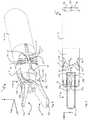
- Fig. 1shows a perspective view of a distal section of an instrument 1 with a tool head 5 articulated to a distal end 2 of an elongated shaft 3.
- a right-handed Cartesian coordinate systemis given, the longitudinal axis of the shaft 3 in the distal direction along the z- Axis runs.
- the tool head 5can be angled in an angled plane yz with respect to the shaft 3, the angled plane yz being spanned by the y-axis and the z-axis.
- two pliers jaw parts 7a, bcan be pivoted independently of one another about a tool axis 8 with respect to the tool head 5, the tool axis running in the y-direction.
- the x-axis and the z-axisthus span a tool plane xz in which the two pliers jaw parts 7a, b can be pivoted independently of one another.
- Independentis intended to mean here that there is no continuous movement coupling between the forceps jaw parts 7. However, the position of a forceps jaw part 7a, b limit the pivoting clearance of the other pliers jaw part 7b, a.
- a bend control cable 9is provided, which runs essentially parallel to the longitudinal axis of the shaft 3 from a proximal-side handle or robot control (not shown) to the tool head 5.
- a tool control cable 11a, bis provided for each forceps jaw part 7a, b, which likewise runs essentially parallel to the longitudinal axis of the shaft 3 from a proximal handle or robot control (not shown) to the tool head 5.
- a convexly curved first rolling surface 13is arranged on the proximal side of the tool head 5.
- R 1radius of curvature
- a corresponding convexly curved second rolling surface 15the first rolling surface 13 rolling on the second rolling surface 15 when the tool head 5 is angled.
- the radius of curvature R 2 of the second rolling surface 15is greater than the radius of curvature R 1 of the first rolling surface 13, so that the first rolling surface 13 at each rolling point with the second rolling surface 15 in the angle plane yz has a larger convex rolling curvature than the second rolling surface, ie ⁇ 1 > ⁇ 2 .
- the angle control cable 9has a first angle control cable section 9a, which leads essentially straight on a third lateral side (the side in the negative y-direction) in the longitudinal direction of the shaft 3 from the shaft 3 to the tool head 5.
- the angle control cable 9has a second angle control cable section 9b, which leads essentially straight on a fourth lateral side diametrically opposite the third lateral side (the side in the positive y-direction) in the longitudinal direction of the shaft 3 from the shaft 3 to the tool head 5.
- Such pull control commandscan be given manually by a handle connected to the bending control cable 9 at a proximal end of the shaft 3 or in an automated manner by a robot control system connected to a proximal end of the shaft 3.
- a robot controlis preferred here, since bending and tool control can be complex.
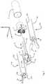
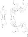
- FIG 3different angled positions of the instrument 1 at different polar angles ⁇ without the angle control cable 9 and without tool control cables 11 a, b are shown.
- the polar angle ⁇where 0 ° ⁇ ⁇ 120 ° here, spans between the longitudinal axis of the shaft 3 running in the z direction and the longitudinal axis of the tool head 5 in the angle plane yz.
- the tool head 5is angled once in the negative y-direction and once in the positive y-direction by 0 ° ⁇ ⁇ 90 °.
- the tool head 5is angled once in the negative y-direction and once in the positive y-direction by 90 ° ⁇ 120 °. Because the radius of curvature R 2 of the second rolling surface 15 is greater than the radius of curvature R 1 of the first rolling surface 13, each point of the tool head sweeps over part of an epicycloid that is not a cardioid. This enables rapid and symmetrical angling in the smallest possible space with, at the same time, the largest possible angular range or polar angle ⁇ .
- FIG Figure 1The partially visible web 17 of the tool head 5 is the side views of FIG Figure 3 good to see.
- the web 17runs in the angle plane yz and divides the first rolling surface 13 into a first section and a second section.
- the second rolling surface 15is analogous by means of a groove 19 running in the angled plane yz (see FIG Fig. 1 ) divided into a first section and a second section.
- the web 17engages at least partially in the groove 19 at every angled position or every polar angle ⁇ of the tool head 5 and thus stabilizes or guides the tool head 5 during the angling in the angled plane yz.
- the web 17is higher here in a central area around the longitudinal axis of the tool head 5 with respect to the first rolling surface 13 than in lateral outer areas.
- the web 19can, on the one hand, hold engagement in the groove 19 at every possible angled position or every possible polar angle ⁇ and, on the other hand, permit the largest possible polar angles ⁇ .
- the web 17tapers slightly in the middle with a kink 20 as in FIG Figures 3a and 3e can be seen.
- the web 17defines two bend control cable guides on the apex side, the bend control cable guides running symmetrically with respect to the longitudinal axis.
- the angle control cable guideseach have a groove 22 for at least partial insertion of the angle control cable 9. In this way, the angle control cable 9 is guided safely and without kinking on the top side on the web 17.
- each of the pliers jaw parts 7a, bcan be pivoted independently of one another about the tool axis 8 running in the y direction in the tool plane xz relative to the tool head 5 between a lateral stop point on the tool head 5 and the stop on the respective other pliers jaw part 7a, b.
- the lateral stop points defined by the tool head 5are arranged so far away from the tool axis 8 that pivot angles ⁇ of more than 90 ° and up to 120 ° are possible.
- the tool control cables 11a, beach have a first tool control cable section 23a, b, a second tool control cable section 25a, b and a third tool control cable section 27a, b, the first tool control cable section 23a, b essentially in the tool plane xz and essentially straight on a first lateral Side (the side in the negative x-direction) in the longitudinal direction of the shaft 3 leads from the shaft 3 to the respective jaw part 7a, b, the second tool control cable section 25a, b essentially in the tool plane xz, essentially straight on one of the first lateral side diametrically opposite second lateral side (the side in the positive x-direction) in the longitudinal direction of the shaft 3 leads from the shaft 3 to the respective jaw part 7a, b, and the third tool control
- the third tool control cable section 27a, bhere connects the first tool control cable section 23a, b to the second tool control cable section 25a, b, so that the tool control cable 11a, b is formed in one piece.
- the third tool control cable section 27a, bruns in a loop shape through the respective Pliers jaw part 7a, b to ensure the positive connection.
- the third tool control cable section 27a, bis here at least partially wound in the form of a helical section on a tool control cable surface 29a, b of the respective jaw part 7a, b.
- the jaw parts 7a, bhere each define the tool control rope surface 29a, b, which is essentially in the form of a cylinder jacket or a cone jacket.
- Each jaw part 7a, bhas a tool section 31a, b extending radially away from the tool control cable surface 29a, b, the third tool control cable section 27a, b running on the tool control cable surface 29a, b in the circumferential direction in front of and behind the tool section 31a, b into the respective jaw part 7a, b and is guided in a loop around the tool axis 8 therein.
- the tool control rope surface 29a, bdefines a diameter D in the tool plane xz (see Figure 8 ).
- the jaw parts 7a, brun here in a slot-shaped tool holder 33 of the tool head 5 that extends in the tool plane, the slot-shaped tool holder 33 being deeper in the longitudinal direction of the shaft 3 (z-direction) than the diameter D of the tool control rope surfaces 29a, b.
- the tool holder 33 of the tool head 5 for holding the jaw parts 7a, bcan be seen better, with A denoting the depth of the slot-shaped tool holder 33
- first tool control cable sections 23a, b and second tool control cable sections 25a, bare each guided parallel through the shaft 3 in the radial direction one above the other.
- the third tool control cable section 27a, bwhich runs in the form of a helical section on the associated tool control cable surface 29a, b, is guided into the respective jaw part 7a, b in a lateral outer region of the tool control cable surface 29a, b.
- the third tool control cable section 27a of the first jaw part 7ais opposite to the third tool control cable section 27b of the second jaw part Spread over the third tool control cable section 27b of the second jaw part 7b from the shaft 3 to the tool sections 31a, b of the jaw parts 7a, b.
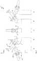
- the spreadingis better Fig. 2 to see.
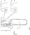
- a pliers jaw part 7ais shown in more detail with two different embodiments of a tool control rope surface 29a, which are each shown as detailed views 8a) and 8b).
- the tool control rope surface 29ais cylindrical and in Figure 8b ) the tool control rope surface 29a is cone-shaped.
- the tool control cable 11a in the form of a helical sectioncan at least partially be wound up on this tool control cable surface 29a.
- openings 35 arranged in the circumferential direction in front of and behind the tool section 31a, bare shown, through which the tool control cable 11a can be guided in the form of a loop into the pliers jaw part 7a.
- the openings 35are arranged here in a lateral outer region of the tool control cable surface 29a in order to spread the tool control cables 11a, b. Is analog Fig. 8 to understand for the second pliers jaw part 7b.
- Fig. 10the loop-shaped implementation of a one-piece tool control cable 11a through the pliers jaw part 7a is shown.
- the tool control cable 11ais here "sewn" into the pliers jaw part 7a and runs in a loop around the central opening for the tool axis 8
- Fig. 11an embodiment is shown in which the tool control cable 11a is formed in two pieces.
- the third tool control cable section 27ahere defines a distal end of the first tool control cable section 23a or that of the second tool control cable section 25a, each of which has an end thickening 37a here.
- the end thickening 37aprevents the tool control cable 11a from slipping when it is actuated and thus ensures a non-positive connection.
- the Figures 10 and 11apply analogously to the second jaw part 7b and the associated second tool control cable 11b.
Landscapes
- Health & Medical Sciences (AREA)
- Surgery (AREA)
- Life Sciences & Earth Sciences (AREA)
- Engineering & Computer Science (AREA)
- Medical Informatics (AREA)
- Biomedical Technology (AREA)
- Heart & Thoracic Surgery (AREA)
- Nuclear Medicine, Radiotherapy & Molecular Imaging (AREA)
- Molecular Biology (AREA)
- Animal Behavior & Ethology (AREA)
- General Health & Medical Sciences (AREA)
- Public Health (AREA)
- Veterinary Medicine (AREA)
- Robotics (AREA)
- Ophthalmology & Optometry (AREA)
- Surgical Instruments (AREA)
Description
Translated fromGermanDie vorliegende Offenbarung betrifft Instrumente, vorzugsweise in Form eines medizinischen Endoskops zum minimalinvasiven Eingriff bei der Diagnose oder chirurgischen Behandlung eines Patienten. Solche Instrumente können allerdings auch als technische Instrumente verwendet werden.The present disclosure relates to instruments, preferably in the form of a medical endoscope, for minimally invasive intervention in the diagnosis or surgical treatment of a patient. Such instruments can, however, also be used as technical instruments.
Medizinische Instrumente dieser Art weisen typischerweise am distalen Ende eines länglichen Schafts einen Werkzeugkopf in Form einer Schere, Zange oder Greifers auf, wobei das Werkzeug über entlang des Schafts geführte Steuerseile mittels einer am proximalen Ende des Schafts angeordneten Handhabe betätigt werden kann. Das Instrument kann auch Teil eines robotergesteuerten Systems sein, bei dem die Handhabe durch eine computergesteuerte Motorik ersetzt ist oder diese unterstützt. Das Werkzeug sitzt dabei häufig auf einem Werkzeugkopf, der seinerseits beweglich sein kann, d.h. gegenüber dem Schaft um die Längsachse drehbar oder gegen diese abwinkelbar. Für diese Bewegungen sind oft zusätzliche Steuerseile und mehrere Schaftabschnitte erforderlich.Medical instruments of this type typically have a tool head in the form of scissors, pliers or grippers at the distal end of an elongated shaft, the tool being able to be actuated via control cables guided along the shaft by means of a handle arranged on the proximal end of the shaft. The instrument can also be part of a robot-controlled system in which the handle is replaced by or supports computer-controlled motor functions. The tool is often seated on a tool head, which in turn can be movable, i.e. rotatable around the longitudinal axis with respect to the shaft or angled against it. Additional control cables and multiple shaft sections are often required for these movements.
Die
Die Bewegungs- und Betätigungskinematik ist auf dem sehr kleinen Bauraum komplex und erfordert eine Vielzahl von gegeneinander beweglichen Komponenten. Der Montageaufwand dieser Vielzahl von gegeneinander beweglichen Komponenten ist entsprechend komplex. Daher sind die bekannten medizinischen Instrumente dieser Art relativ teuer und nicht für die einmalige Verwendung geeignet. Bei mehrmaliger Verwendung kann allerdings die Sterilisierung wegen der Vielzahl von gegeneinander beweglichen Komponenten aufwändig sein.The kinematics of movement and actuation are complex in the very small installation space and require a large number of counterparts moving components. The assembly effort of this multitude of mutually movable components is correspondingly complex. Therefore, the known medical instruments of this type are relatively expensive and not suitable for single use. With repeated use, however, the sterilization can be complex because of the large number of components that can move relative to one another.
Die vorliegende Offenbarung stellt ein Instrument bereit, das für die einmalige Verwendung geeignet ist und weniger gegeneinander bewegliche Komponenten aufweist und dabei einen hohen Grad an Bewegungs- und Betätigungsfreiheit für das Werkzeug sicherstellt.The present disclosure provides an instrument that is suitable for single use and has fewer mutually movable components while ensuring a high degree of freedom of movement and actuation for the tool.
Gemäß der vorliegenden Erfindung weist das Instrument einen an einem distalen Ende eines länglichen Schafts angelenkten Werkzeugkopf und ein Maulteilpaar zum Scheren, Kneifen oder Greifen auf, wobei das Maulteilpaar ein erstes Maulteil und ein zweites Maulteil aufweist. Der Werkzeugkopf ist dabei gegenüber einer Längsachse des Schafts um einen Polarwinkel θ in einer zur Längsachse parallelen Abwinkelebene mittels mindestens zwei aneinander anliegender konvex gekrümmter Wälzflächen definiert abwinkelbar. Das erste Maulteil und das zweite Maulteil sind in einer zur Abwinkelebene im Wesentlichen senkrechten Werkzeugebene unabhängig voneinander gegenüber dem Werkzeugkopf verschwenkbar und definieren jeweils eine im Wesentlichen zylindermantelförmige oder kegelmantelförmige Werkzeugsteuerseilfläche, auf der jeweils zumindest ein Werkzeugsteuerseilabschnitt in Form eines Wendelabschnitts teilweise auf- bzw. abwickelbar ist. Dabei ist die erste Wälzfläche mittels eines in der Abwinkelebene verlaufenden Stegs in einen ersten Abschnitt und einen zweiten Abschnitt aufgeteilt und die zweite Wälzfläche mittels einer in der Abwinkelebene verlaufenden Nut in einen ersten Abschnitt und einen zweiten Abschnitt aufgeteilt. Der Steg greift dabei bei jeder Abwinkelposition (Polarwinkel θ) des Werkzeugkopfs zumindest teilweise in die Nut ein. Damit wird der Werkzeugkopf auf einfache Weise ohne zusätzliche Komponenten senkrecht zur Abwinkelebene fixiert. Auch ein unerwünschtes Verdrehen der Wälzflächen gegeneinander außerhalb der Abwinkelebene wird durch den steten Steg-Nut-Eingriff verhindert. Der Steg definiert zudem scheitelseitig zwei Abwinkelsteuerseilführungen, wobei die Abwinkelsteuerseilführungen symmetrisch bezüglich der Längsachse verlaufen. Beispielsweise kann die Abwinkelsteuerseilführungen eine Rille zur mindestens teilweisen Einlage eines Abwinkelsteuerseils aufweisen. Damit wird im Zusammenspiel mit dem Steg-Nut-Eingriff ein Abknicken und Abrutschen des Abwinkelsteuerseils vom Steg verhindert.According to the present invention, the instrument has a tool head articulated to a distal end of an elongated shaft and a pair of jaws for shearing, pinching or gripping, the pair of jaws having a first jaw part and a second jaw part. The tool head can be angled in a defined manner with respect to a longitudinal axis of the shaft by a polar angle θ in an angle plane parallel to the longitudinal axis by means of at least two convexly curved rolling surfaces abutting one another. The first jaw part and the second jaw part can be pivoted independently of one another relative to the tool head in a tool plane that is essentially perpendicular to the angle plane and each define an essentially cylinder jacket-shaped or conical jacket-shaped tool control cable surface on which at least one tool control cable section in the form of a helical section can be partially wound or unwound . The first rolling surface is divided into a first section and a second section by means of a web running in the angled plane, and the second rolling surface is divided into a first section and a second section by means of a groove running in the angled plane. The web engages at least partially in the groove at every angle position (polar angle θ) of the tool head. In this way, the tool head is fixed in a simple manner without additional components perpendicular to the angled plane. Unwanted twisting of the rolling surfaces against each other outside the angle plane is also prevented by the constant web-groove engagement. The web also defines two bend control cable guides on the apex side, the bend control cable guides running symmetrically with respect to the longitudinal axis. For example, the angle control cable guides can have a groove for at least partial insertion of an angle control cable. This, in conjunction with the web-groove engagement, prevents the bend control cable from kinking and slipping off the web.
Damit können die Werkzeugsteuerseile knoten- und fittingfrei und ohne Seilrollen geführt werden. Dies reduziert die Komplexität, Bauteilevielfalt und Produktionskosten derart, dass das Instrument zur EinmalVerwendung geeignet ist. Die Werkzeugsteuerseile können wegen der wendelabschnittsförmigen Führung auf der zylindermantel- oder kegelmantelförmigen Werkzeugsteuerseilfläche bevorzugt ein gut gleitendes Kunstfasermaterial wie beispielsweise Aramidfasern, Ultra-Hochmolekulargewichtige PE-Fasern (UHMWPE), Kevlar®, Dyneema®, Vectran® und/oder Carbon-Nanotubes aufweisen.This means that the tool control cables can be routed without knots or fittings and without pulleys. This reduces the complexity, the variety of components and the production costs in such a way that the instrument is suitable for single use. Because of the helical section-shaped guidance on the cylindrical jacket or conical jacket-shaped tool control cable surface, the tool control cables can preferably have a smooth-sliding synthetic fiber material such as aramid fibers, ultra-high molecular weight PE fibers (UHMWPE), Kevlar®, Dyneema®, Vectran® and / or carbon nanotubes.
Optional kann sich eine erste der mindestens zwei Wälzflächen an einem proximalen Endbereich des Werkzeugkopfs und eine zweite der mindestens zwei Wälzflächen an einem distalen Schaftende befinden, wobei die erste Wälzfläche an jedem Wälzpunkt mit der zweiten Wälzfläche in der Abwinkelebene eine größere konvexe Abrollkrümmung hat als die zweite Wälzfläche. Mit "Krümmung" sei hier das betragsmäßige Krümmungsmaß κ=1/r als Kehrwert des Krümmungsradius r des lokalen Schmiegekreises an jedem Punkt entlang einer Kurve gemeint. Ob eine Links- bzw. Rechtskrümmung vorliegt, d.h. das Vorzeichen der Krümmung, sei hierin relativ zum zugehörigen Bauteilkörper über die Attribute "konvex" bzw. "konkav" definiert. Die Abwinkelebene kann relativ zu einer proximalseitigen Handhabe bzw. Robotersteuerung um die Längsachse drehbar oder fix sein. Bei fixer Abwinkelebene kann ggf. das ganze Instrument gedreht werden, um das Werkzeug in eine gewünschte Raumrichtung abwinkeln zu können.Optionally, a first of the at least two rolling surfaces can be located on a proximal end region of the tool head and a second of the at least two rolling surfaces on a distal end of the shank, the first rolling surface having a greater convex rolling curvature than the second at each rolling point with the second rolling surface in the angled plane Rolling surface. With "curvature" is meant here the amount of curvature κ = 1 / r as the reciprocal of the radius of curvature r of the local osculating circle at every point along a curve. Whether there is a left or right curvature, ie the sign of the curvature, is here relative to the associated component body Defined via the attributes "convex" or "concave". The angled plane can be rotatable or fixed about the longitudinal axis relative to a handle or robot control on the proximal side. With a fixed angle plane, the entire instrument can be rotated, if necessary, in order to be able to angle the tool in a desired spatial direction.
Durch die größere konvexe Krümmung der werkzeugseitigen ersten Wälzfläche auf der weniger konvex gekrümmten schaftseitigen zweiten Wälzfläche kann eine hohe Beweglichkeit des Werkzeugkopfes erreicht werden, ohne mehrere gegeneinander bewegliche Gelenkabschnitte vorzusehen. Der Polarwinkel θ kann dadurch größer als 90° sein und ggf. bis zu 120° und mehr betragen. Außerdem bewegt sich dadurch der Schwerpunkt des Werkzeugkopfes beim Abwinkeln weniger weit von der Längsachse des Schafts weg, sodass eine kompaktere Funktionsweise erreicht wird. Gegenüber einem herkömmlichen Abwinkein über eine feste Abwinkelachse hat das hierein offenbarte Instrument hingegen den Vorteil, dass die Steuerseile nicht zu sehr abgeknickt werden. Ein Krümmungsverhältnis κ1/κ2 zwischen erster Abrollkrümmung κ1 und zweiter Abrollkrümmung κ2 von 1,05 bis 1,5 hat sich hierbei als vorteilhaft herausgestellt, insbesondere der Bereich um 1,2 von 1,1 bis 1,3.Due to the greater convex curvature of the tool-side first rolling surface on the less convexly curved shaft-side second rolling surface, a high degree of mobility of the tool head can be achieved without providing a plurality of mutually movable joint sections. The polar angle θ can therefore be greater than 90 ° and possibly up to 120 ° and more. In addition, the center of gravity of the tool head moves less far away from the longitudinal axis of the shaft when it is bent, so that a more compact function is achieved. In contrast to conventional angling via a fixed angling axis, the instrument disclosed herein has the advantage that the control cables are not bent too much. A curvatureratio κ 1 / κ2 between first rolling curvature κ1 and second rolling curvature κ2 of 1.05 to 1.5 has proven to be advantageous, in particular the range around 1.2 from 1.1 to 1.3.
Die Wälzflächen können im Wesentlichen zylinderförmig mit einer konstanten Abrollkrümmung ausgestaltet sein oder mit veränderlicher Krümmung, wie etwa in der Abwinkelebene elliptisch oder parabelförmig. Die Wälzflächen müssen dabei nicht die gleiche Form haben, wobei es allerdings vorteilhaft ist, wenn die Wälzflächen jeweils bezüglich der Längsachse einen symmetrischen Krümmungsverlauf haben, wenn das Abwinkeln in die eine oder andere Richtung nicht unterschiedlich ablaufen soll.The rolling surfaces can be designed essentially cylindrical with a constant rolling curvature or with a variable curvature, such as elliptical or parabolic in the angled plane. The rolling surfaces do not have to have the same shape, although it is advantageous if the rolling surfaces each have a symmetrical course of curvature with respect to the longitudinal axis if the angling in one or the other direction should not take place differently.
Optional können die mindestens zwei Wälzflächen formschlüssig ineinander greifen und dazu vorzugsweise ineinandergreifende Verzahnungen aufweisen. Dadurch verrutschen die Wälzflächen in der Abwinkelebene nicht gegeneinander, sodass ein definiertes Abwinkeln sichergestellt ist. Alternativ oder zusätzlich können sie zu diesem Zweck in Reibschluss miteinander stehen. Vorzugsweise haben die Verzahnungen auf den korrespondierenden Wälzflächen das gleiche Modul bzw. die gleiche Zahnradteilung.Optionally, the at least two rolling surfaces can interlock in a form-fitting manner and for this purpose preferably have interlocking teeth. As a result, the rolling surfaces do not slip against one another in the angled plane, so that defined angling is ensured. Alternatively or additionally, they can be in frictional engagement with one another for this purpose. The toothings on the corresponding rolling surfaces preferably have the same module or the same gear pitch.
Optional kann der Steg in einem Zentralbereich um die Längsachse höher bezüglich der ersten Wälzfläche sein als in lateralen Außenbereichen. Dies ist besonders vorteilhaft, wenn der Steg scheitelseitig ein Abwinkelsteuerseil führt, das dadurch weniger abgeknickt wird, wenn der Werkzeugkopf abgewinkelt wird. Es können somit kostengünstige Zugseile mit Kunststofffasern verwendet werden.Optionally, the web can be higher in a central area around the longitudinal axis with respect to the first rolling surface than in lateral outer areas. This is particularly advantageous if the crosspiece guides an angle control cable on the apex side, which is therefore less kinked when the tool head is angled. Inexpensive pull ropes with plastic fibers can thus be used.
Optional kann der Steg symmetrisch bezüglich der Längsachse in der Abwinkelebene mindestens abschnittsweise eine Stegkrümmung definieren, wobei die Stegkrümmung kleiner ist als die erste Abrollkrümmung. Der Krümmungskreismittelpunkt bzw. die Krümmungskreismittelpunkte können (bei einem Polarwinkel von 0°) dabei versetzt zur Längsachse liegen.Optionally, the web can define a web curvature symmetrically with respect to the longitudinal axis in the angled plane, at least in sections, the web curvature being smaller than the first rolling curvature. The center of the circle of curvature or the centers of the circle of curvature can be offset from the longitudinal axis (with a polar angle of 0 °).
Optional kann der Steg einen zentralen Knick in der Abwinkelebene definieren und/oder mindestens abschnittsweise die Stegkrümmung mit dem Abstand zur Längsachse abnehmen. Der Steg kann also in der Abwinkelebene mittig spitzförmig zulaufen oder abgerundet sein, etwa durch eine Parabel beschreibbar oder zumindest annäherbar.Optionally, the web can define a central bend in the angled plane and / or at least in sections the web curvature can decrease with the distance from the longitudinal axis. The web can therefore taper to a point in the center in the angled plane or be rounded, for example describable or at least approximating by a parabola.
Optional kann das Instrument ein im Wesentlichen in der Abwinkelebene verlaufendes Abwinkelsteuerseil aufweisen, das einen ersten Abwinkelsteuerseilabschnitt, einen zweiten Abwinkelsteuerseilabschnitt und einen dritten Abwinkelsteuerseilabschnitt aufweist, wobei der erste Abwinkelsteuerseilabschnitt im Wesentlichen gerade auf einer dritten lateralen Seite in Längsrichtung des Schafts vom Schaft zum Werkzeugkopf führt, wobei der zweite Abwinkelsteuerseilabschnitt im Wesentlichen gerade auf einer der dritten lateralen Seite diametral gegenüberliegenden vierten lateralen Seite in Längsrichtung des Schafts vom Schaft zum Werkzeugkopf führt, und sich der dritte Abwinkelsteuerseilabschnitt jeweils am ersten und zweiten Abwinkelsteuerseilabschnitt anschließt und in kraftschlüssiger Verbindung mit dem Werkzeugkopf steht. Dabei kann der dritte Abwinkelsteuerseilabschnitt mäanderförmig durch den Werkzeugkopf geführt sein. Damit wird eine reibschlüssige Kopplung zwischen dem Abwinkelsteuerseil und dem Werkzeugkopf erzielt, sodass das Abwinkelsteuerseil zügelartig mittels Zugkraft den Werkzeugkopf zur dritten lateralen Seite bzw. zur vierten lateralen Seite hin abwinkeln kann. Der dritte Abwinkelsteuerseilabschnitt kann dabei den ersten und zweiten Abwinkelsteuerseilabschnitt verbinden. Das Abwinkelsteuerseil könnte dann zur Reduktion von Komponenten einstückig ausgebildet sein. Alternativ zu einer einstückigen Ausbildung kann das Abwinkelsteuerseil zweiteilig ausgebildet sein. Der dritte Abwinkelsteuerseilabschnitt kann dabei jeweils ein Abwinkelsteuerseilende des ersten und zweiten Abwinkelsteuerseilabschnitts definieren, wobei das jeweilige Abwinkelsteuerseilende durch Reibschluss, Schlingenführung und/oder eine Endverdickung kraftschlüssig mit dem Werkzeugkopf gekoppelt sein kann. Das Abwinkelsteuerseil kann vorzugsweise das gleiche Material aufweisen wie die Werkzeugsteuerseile oder auch anders ausgestaltet sein.Optionally, the instrument can have a bend control cable which runs essentially in the bend plane and which has a first An angle control cable section, a second angle control cable section and a third angle control cable section, wherein the first angle control cable section leads essentially straight on a third lateral side in the longitudinal direction of the shaft from the shaft to the tool head, the second angle control cable section essentially straight on a fourth lateral side that is diametrically opposite the third lateral side Side leads in the longitudinal direction of the shaft from the shaft to the tool head, and the third angle control cable section is connected to the first and second angle control cable section and is in a force-locking connection with the tool head. The third angle control cable section can be guided through the tool head in a meandering shape. This achieves a frictional coupling between the angle control cable and the tool head, so that the angle control cable can bend the tool head towards the third lateral side or the fourth lateral side in the manner of a rein by means of tensile force. The third angle control cable section can connect the first and second angle control cable section. The angle control cable could then be designed in one piece to reduce the number of components. As an alternative to a one-piece design, the angle control cable can be designed in two parts. The third bend control cable section can define a bend control cable end of the first and second bend control cable section, the respective bend control cable end being able to be positively coupled to the tool head by frictional engagement, loop guidance and / or an end thickening. The angle control cable can preferably have the same material as the tool control cables or also be configured differently.
Optional kann die Werkzeugsteuerseilfläche in der Werkzeugebene einen Durchmesser definieren, wobei die Maulteile in einer schlitzförmigen in der Werkzeugebene verlaufenden Werkzeugaufnahme des Werkzeugkopfs über eine gemeinsame senkrecht zur Werkzeugebene verlaufende Werkzeugachse gelagert sind, wobei die schlitzförmige Werkzeugaufnahme in der Längsrichtung tiefer ist als der Durchmesser der Werkzeugsteuerseilflächen. Mit dieser Option werden ebenfalls die Montage und der Aufbau des Werkzeugkopfs vereinfacht.Optionally, the tool control rope surface can define a diameter in the tool plane, the jaw parts in a slot-shaped tool holder of the tool head running in the tool plane over a common one perpendicular to the tool plane extending tool axis are stored, wherein the slot-shaped tool holder is deeper in the longitudinal direction than the diameter of the tool control rope surfaces. This option also simplifies the assembly and construction of the tool head.
Erfindungsgemäß weist das Instrument ein erstes Werkzeugsteuerseil für das erste Maulteil und ein zweites Werkzeugsteuerseil für das zweite Maulteil auf, wobei jedes der Werkzeugsteuerseile einen ersten Werkzeugsteuerseilabschnitt, einen zweiten Werkzeugsteuerseilabschnitt und einen dritten Werkzeugsteuerseilabschnitt aufweist, wobei der erste Werkzeugsteuerseilabschnitt im Wesentlichen in der Werkzeugebene und im Wesentlichen gerade auf einer ersten lateralen Seite in Längsrichtung des Schafts vom Schaft zum jeweiligen Maulteil führt, wobei der zweite Werkzeugsteuerseilabschnitt im Wesentlichen in der Werkzeugebene im Wesentlichen gerade auf einer der ersten lateralen Seite diametral gegenüberliegenden zweiten lateralen Seite in Längsrichtung des Schafts vom Schaft zum jeweiligen Maulteil führt, und sich der dritte Werkzeugsteuerseilabschnitt jeweils am ersten und zweiten Werkzeugsteuerseilabschnitt anschließt und in kraftschlüssiger Verbindung mit dem jeweiligen Maulteil steht. Dabei kann der dritte Werkzeugsteuerseilabschnitt mäanderförmig durch das zugehörige Maulteil geführt sein. Damit wird eine reibschlüssige Kopplung zwischen dem Werkzeugsteuerseil und dem zugehörigen Maulteil erzielt, sodass das Werkzeugsteuerseil zügelartig mittels Zugkraft das zugehörige Maulteil zur ersten lateralen Seite bzw. zur zweiten lateralen Seite hin auslenken kann. Der dritte Werkzeugsteuerseilabschnitt kann dabei jeweils den ersten und zweiten Werkzeugsteuerseilabschnitt verbinden. Die Werkzeugsteuerseile könnten dann zur Reduktion von Komponenten jeweils einstückig ausgebildet sein. Alternativ zu einer einstückigen Ausbildung können die Werkzeugsteuerseile jeweils zweiteilig ausgebildet sein. Der dritte Werkzeugsteuerseil kann dabei jeweils ein Werkzeugsteuerseilende des ersten und zweiten Werkzeugsteuerseilabschnitts definieren, wobei das jeweilige Werkzeugsteuerseilende durch Reibschluss, Schlingenführung und/oder eine Endverdickung kraftschlüssig mit dem zugehörigen Maulteil gekoppelt sein kann.According to the invention, the instrument has a first tool control cable for the first jaw part and a second tool control cable for the second jaw part, each of the tool control cables having a first tool control cable section, a second tool control cable section and a third tool control cable section, the first tool control cable section essentially in the tool plane and essentially leads straight on a first lateral side in the longitudinal direction of the shaft from the shaft to the respective jaw part, the second tool control cable section essentially in the tool plane essentially straight on a second lateral side diametrically opposite the first lateral side in the longitudinal direction of the shaft from the shaft to the respective jaw part , and the third tool control cable section is connected to the first and second tool control cable section and is in frictional connection with the respective jaw part. The third tool control cable section can be guided in a meandering shape through the associated jaw part. This achieves a frictional coupling between the tool control cable and the associated jaw part, so that the tool control cable can deflect the associated jaw part towards the first lateral side or the second lateral side by means of a tensile force. The third tool control cable section can connect the first and second tool control cable sections. The tool control cables could then each be designed in one piece to reduce the number of components. As an alternative to a one-piece construction, the tool control cables can each be constructed in two parts. The third tool control cable can define a tool control cable end of the first and second tool control cable section, wherein the respective end of the tool control cable can be non-positively coupled to the associated jaw part by means of frictional engagement, loop guidance and / or an end thickening.
Optional kann der dritte Werkzeugsteuerseilabschnitt jeweils zumindest teilweise in Form eines Wendelabschnitts auf der Werkzeugsteuerseilfläche des jeweiligen Maulteils aufgewickelt sein. Damit wird der Aufbau und die Montage des der Werkzeugsteuerseile und der Maulteile vereinfacht.Optionally, the third tool control cable section can in each case be wound at least partially in the form of a helical section on the tool control cable surface of the respective jaw part. This simplifies the construction and assembly of the tool control cables and the jaw parts.
Optional kann jedes Maulteil einen von der Werkzeugsteuerseilfläche radial weg erstreckenden Werkzeugabschnitt aufweisen, wobei der auf der Werkzeugsteuerseilfläche verlaufende dritte Werkzeugsteuerseilabschnitt in Umfangsrichtung vor und hinter dem Werkzeugabschnitt in das jeweilige Maulteil und darin schlingenförmig geführt ist. Damit wird eine hohe Auslenkungsamplitude für die Maulteile ermöglicht.Optionally, each jaw part can have a tool section extending radially away from the tool control cable surface, the third tool control cable section running on the tool control cable surface being guided in the circumferential direction in front of and behind the tool section into the respective jaw part and therein. This enables a high amplitude of deflection for the jaw parts.
Erfindungsgemäß ist der auf der Werkzeugsteuerseilfläche verlaufende dritte Werkzeugsteuerseilabschnitt in einem lateralen Außenbereich der Werkzeugsteuerseilfläche in das jeweilige Maulteil geführt. Dadurch wird der dritte Werkzeugsteuerseilabschnitt des ersten Maulteils gegenüber dem dritten Werkzeugsteuerseilabschnitt des zweiten Maulteils vom Schaft zu den Maulteilen hin aufgespreizt, wobei die Werkzeugsteuerseile in radialer Richtung übereinander parallel durch den Schaft geführt sein können.According to the invention, the third tool control cable section running on the tool control cable surface is guided into the respective jaw part in a lateral outer region of the tool control cable surface. As a result, the third tool control cable section of the first jaw part is spread apart from the third tool control cable section of the second jaw part from the shaft to the jaw parts, the tool control cables being able to be guided parallel through the shaft in the radial direction one above the other.
Die Offenbarung ist nachfolgend anhand von in den Zeichnungen dargestellten Ausführungsbeispielen näher erläutert. Es zeigen:
Fig. 1 eine perspektivische Ansicht auf einen distalen Abschnitt eines Ausführungsbeispiels eines Instruments gemäß der vorliegenden Offenbarung;Fig. 2 eine Seitenansicht auf die Abwinkelebene eines distalen Abschnitts eines Ausführungsbeispiels eines Instruments gemäß der vorliegenden Offenbarung;Fig. 3a-e fünf Seitenansichten auf die Abwinkelebene eines distalen Abschnitts eines Ausführungsbeispiels eines Instruments gemäß der vorliegenden Offenbarung in jeweils unterschiedlichen Abwinkelpositionen;Fig. 4 eine Seitenansicht auf die Werkzeugebene eines distalen Abschnitts eines Ausführungsbeispiels eines Instruments gemäß der vorliegenden Offenbarung;Fig. 5a-f sechs Seitenansichten auf die Werkzeugebene eines distalen Abschnitts eines Ausführungsbeispiels eines Instruments gemäß der vorliegenden Offenbarung in jeweils unterschiedlichen Auslenkungspositionen der Maulteile;Fig. 6 eine perspektivische Ansicht auf einen Teilschnitt eines distalen Abschnitts eines Ausführungsbeispiels eines Instruments gemäß der vorliegenden Offenbarung;Fig. 7 eine perspektivische Explosionsansicht auf einen distalen Abschnitt eines Ausführungsbeispiels eines Instruments gemäß der vorliegenden Offenbarung;Fig. 8 eine perspektivische Ansicht auf ein Maulteil eines Ausführungsbeispiels eines Instruments gemäß der vorliegenden Offenbarung;Fig.9 eine perspektivische Ansicht auf einen Werkzeugkopf und ein Abwinkelsteuerseil eines Ausführungsbeispiels eines Instruments gemäß der vorliegenden Offenbarung;Fig. 10 perspektivische Ansichten von zwei Seiten auf ein Maulteil und ein Werkzeugsteuerseil gemäß einer ersten Ausführungsform eines Ausführungsbeispiels eines Instruments gemäß der vorliegenden Offenbarung; undFig. 11 perspektivische Ansichten von zwei Seiten auf ein Maulteil und ein Werkzeugsteuerseil gemäß einer zweiten Ausführungsform eines Ausführungsbeispiels eines Instruments gemäß der vorliegenden Offenbarung.
Fig. 1 a perspective view of a distal portion of an embodiment of an instrument according to the present disclosure;Fig. 2 a side view of the angled plane of a distal portion of an embodiment of an instrument according to the present disclosure;Figures 3a-e five side views of the angled plane of a distal section of an exemplary embodiment of an instrument according to the present disclosure in respectively different angled positions;Fig. 4 a side view of the tool plane of a distal portion of an embodiment of an instrument according to the present disclosure;Figures 5a-f six side views of the tool plane of a distal section of an embodiment of an instrument according to the present disclosure in different deflection positions of the jaw parts;Fig. 6 a perspective view of a partial section of a distal portion of an embodiment of an instrument according to the present disclosure;Fig. 7 an exploded perspective view of a distal portion of an embodiment of an instrument according to the present disclosure;Fig. 8 a perspective view of a jaw part of an embodiment of an instrument according to the present disclosure;Fig. 9 a perspective view of a tool head and an angle control cable of an embodiment of an instrument according to the present disclosure;Fig. 10 perspective views from two sides of a jaw part and a tool control cable according to a first embodiment of an embodiment of an instrument according to the present disclosure; andFig. 11 perspective views from two sides of a jaw part and a tool control cable according to a second embodiment of an embodiment of an instrument according to the present disclosure.
Zum Abwinkeln des Werkzeugkopfs 5 gegenüber dem Schaft 3 ist ein Abwinkelsteuerseil 9 vorgesehen, das im Wesentlichen parallel zur Längsachse des Schafts 3 von einer proximalseitigen Handhabe oder Robotersteuerung (nicht gezeigt) zum Werkzeugkopf 5 verläuft. Für das Verschwenken der Zangenmaulteile 7a,b ist für jedes Zangenmaulteil 7a,b jeweils ein Werkzeugsteuerseil 11 a,b vorgesehen, das ebenfalls im Wesentlichen parallel zur Längsachse des Schafts 3 von einer proximalseitigen Handhabe oder Robotersteuerung (nicht gezeigt) zum Werkzeugkopf 5 verläuft.To bend the
In der Seitensicht der
Um ein Verrutschen der Wälzflächen 13, 15 gegeneinander zu vermeiden und ein definiertes Abwälzen zu ermöglichen, ist sind hier jeweils ineinandergreifende Verzahnungen auf den beiden Wälzflächen 13, 15 vorgesehen. Das Abwinkelsteuerseil 9 weist einen ersten Abwinkelsteuerseilabschnitt 9a auf, der im Wesentlichen gerade auf einer dritten lateralen Seite (die Seite in negative y-Richtung) in Längsrichtung des Schafts 3 vom Schaft 3 zum Werkzeugkopf 5 führt. Außerdem weist das Abwinkelsteuerseil 9 einen zweiten Abwinkelsteuerseilabschnitt 9b auf, der Wesentlichen gerade auf einer der dritten lateralen Seite diametral gegenüberliegenden vierten lateralen Seite (die Seite in positive y-Richtung) in Längsrichtung des Schafts 3 vom Schaft 3 zum Werkzeugkopf 5 führt. Bei Zug am ersten Abwinkelsteuerseilabschnitt 9a winkelt der Werkzeugkopf 5 in negative y-Richtung ab, und bei Zug am zweiten Abwinkelsteuerseilabschnitt 9b winkelt der Werkzeugkopf 5 in positive y-Richtung ab. Solche Zugsteuerbefehle können durch eine mit dem Abwinkelsteuerseil 9 verbundene Handhabe an einem proximalen Ende des Schafts 3 manuell oder durch ein an einem proximalen Ende des Schafts 3 angeschlossenes Robotersteuersystem automatisiert gegeben werden. Eine Robotersteuerung ist hier bevorzugt, da eine Abwinklungs- und Werkzeugsteuerung komplex sein kann.In order to prevent the rolling surfaces 13, 15 from slipping against one another and to enable defined rolling, are here In each case interlocking toothings are provided on the two rolling
In
Ein in
Der Steg 17 definiert scheitelseitig zwei Abwinkelsteuerseilführungen, wobei die Abwinkelsteuerseilführungen symmetrisch bezüglich der Längsachse verlaufen. Die Abwinkelsteuerseilführungen weisen jeweils eine Rille 22 zur mindestens teilweisen Einlage des Abwinkelsteuerseils 9 auf. Damit wird das Abwinkelsteuerseil 9 sicher und ohne Abknicken scheitelseitig auf dem Steg 17 geführt.The
In den Seitenansichten der
In dem perspektivischen Teilschnitt von
Der dritte Werkzeugsteuerseilabschnitt 27a,b, ist hierbei zumindest teilweise in Form eines Wendelabschnitts auf einer Werkzeugsteuerseilfläche 29a,b, des jeweiligen Maulteils 7a,b aufgewickelt. Die Maulteile 7a,b definieren hier jeweils die im Wesentlichen zylindermantel- oder kegelmantelförmige Werkzeugsteuerseilfläche 29a,b. Jedes Maulteil 7a,b weist dabei einen sich von der Werkzeugsteuerseilfläche 29a,b radial weg erstreckenden Werkzeugabschnitt 31a,b auf, wobei der auf der Werkzeugsteuerseilfläche 29a,b verlaufende dritte Werkzeugsteuerseilabschnitt 27a,b in Umfangsrichtung vor und hinter dem Werkzeugabschnitt 31a,b in das jeweilige Maulteil 7a,b und darin schlingenförmig um die Werkzeugachse 8 geführt ist. Die Werkzeugsteuerseilfläche 29a,b definiert in der Werkzeugebene x-z einen Durchmesser D (siehe
In
In
In
In
Die nummerierten Bezeichnungen der Bauteile oder Bewegungsrichtungen als "erste", "zweite", "dritte" usw. sind hierin rein willkürlich zur Unterscheidung der Bauteile oder Bewegungsrichtungen untereinander gewählt und können beliebig anders gewählt werden. Es ist damit kein Bedeutungsrang verbunden.The numbered designations of the components or directions of movement as “first”, “second”, “third” etc. are chosen here purely arbitrarily to distinguish the components or directions of movement from one another and can be chosen differently as desired. It is not associated with any rank of importance.
Die beschriebenen Ausführungsformen sind als illustrative Beispiele zu verstehen und stellen keine abschließende Liste von möglichen Ausführungsformen dar. Jedes Merkmal, das im Rahmen einer Ausführungsform offenbart wurde, kann allein oder in Kombination mit einem oder mehreren anderen Merkmalen verwendet werden, unabhängig davon, in welcher Ausführungsform die Merkmale jeweils beschrieben wurden. Im Übrigen soll hierin weder der Begriff "aufweisen" zusätzliche andere Merkmale oder Verfahrensschritte ausschließen noch soll "ein" oder "eine" eine Mehrzahl ausschließen.The described embodiments are to be understood as illustrative examples and do not represent an exhaustive list of possible ones Each feature that has been disclosed in the context of an embodiment can be used alone or in combination with one or more other features, regardless of the embodiment in which the features were described in each case. Furthermore, the term “having” is not intended to exclude additional other features or method steps, nor is “a” intended to exclude a plurality.
Claims (17)
- An instrument (1) with- a tool head (5) which is articulated on a distal end (2) of an elongate shank (3),- a jaw part pair (7a, 7b) for shear cutting, pinching or gripping,
wherein the jaw part pair (7a,b) comprises a first jaw part (7a) and a second jaw part (7b), and- a first tool control cable (11a) for the first jaw part (7a) and a second tool control cable (11b) for the second jaw part (7b);wherein the tool head (5) can be bent in a defined manner with respect to a longitudinal axis of the shank (3) about a polar angle (θ) in a bending plane (y-z) which is parallel to the longitudinal axis, by way of at least two convexly curved rolling surfaces (13, 15) which bear on one another,
wherein the first jaw part (7a) and the second jaw part (7b) are pivotable with respect to the tool head (5) independently of one another in a tool plane (x-z) which is essentially perpendicular to the bending plane (y-z), and
wherein the first jaw part (7a) and the second jaw part (7b) each define a cylinder-jacket-shaped or cone-jacket-shaped tool control cable surface (29a,b), on which at least one tool control cable section (27a,b) in the form of spiral section can be partly wound on and wound off,
wherein a first rolling surface (13) of the at least two rolling surfaces (13, 15) is divided by way of a web (17) which runs in the bending plane (y-z) into a first section and a second section, and a second rolling surface (15) of the at least two rolling surfaces (13, 15) is divided by way of a groove (19) which runs in the bending plane (y-z) into a first section and a second section, wherein the web (17) at each bending position of the tool head (5) engages at least partly into the groove (19) wherein the web (17) at the apex side defines two bending control cable guides,
wherein the bending control cable guides run symmetrically with respect to the longitudinal axis,
wherein each of the tool control cables (11a,b) comprises a first tool control cable section (23a,b) a second tool control cable section (25a,b) and a third tool control cable section (27a,b), wherein the first tool control cable section (23a,b) leads essentially in the tool plane (x-z) and essentially in a straight line on a first lateral side in the longitudinal direction of the shank (3) from the shank to the respective jaw part (7a,b), wherein the second tool control cable section (25a,b) leads essentially in the tool plane (x-z) essentially in a straight line on a second lateral side which is diametrically opposite the first lateral side, in the longitudinal direction of the shank (3) from the shank (3) to the respective jaw part (7a,7b), and the third tool control cable section (27a,b) connects to the first and the second tool control cable section (25a,b, 27a,b) and is non-positively connected to the respective jaw part (7a,7b), wherein the third tool control cable section (27a) of the first jaw part (7a) is spread out with respect to the third tool control cable section (27b) of the second jaw part (7b), from the shank (3) towards the jaw parts (7a, b) in the bending plane (y-z), wherein the third tool control cable section (27a, b) which runs on the tool control cable surface (29a,b) is led in a lateral outer region of the tool control cable surface (29a,b) into the respective jaw part (7a,b). - An instrument (1) according to claim 1, wherein a first (13) of the at least two rolling surfaces (13, 15) are located at a proximal end region of the tool head (5) and a second (15) of the at least two rolling surfaces (13, 15) is located on the distal shank end (2), wherein the first rolling surface (13) at each rolling point with the second rolling surface (15) in the bending plane (y-z) has a greater convex rolling curvature than the second rolling surface (15).
- An instrument (1) according to claim 2, wherein the at least two rolling surfaces (13, 15) comprise toothings which engage into one another.
- An instrument (1) according to one of the preceding claims, wherein the web (17) in a central region about the longitudinal axis is higher with respect to the first rolling surface (13) than in the lateral outer regions.
- An instrument (1) according to one of the preceding claims, wherein the web (17) symmetrically with respect to the longitudinal axis in the bending plane (y-z) at least in sections defines web curvature, wherein the web curvature is smaller than the first rolling curvature.
- An instrument (1) according to one of the preceding claims, wherein the web (17) defines a central angle bend (20) in the bending plane (y-z) and/or at least in sections the web curvature decreases with the distance to the longitudinal axis.
- An instrument (1) according to one of the preceding claims, wherein the bending control cable guides comprise a groove (22) for the at least partial insertion of a bending control cable (9).
- An instrument (1) according to one of the preceding claims, with a bending control cable (9) which runs essentially in the bending plane (y-z) and which comprises a first bending control cable section (9a), a second bending control cable section (9b) and a third bending control cable section (9a), wherein the first bending control cable section (9a) leads in an essentially straight line on a third lateral side in the longitudinal direction of the shank (3) from the shank (3) to the tool head (5), wherein the second bending control cable section (9b) leads essentially in a straight line on a fourth lateral side which is diametrically opposite to the third lateral side, in the longitudinal direction of the shank (3) from the shank (3) to the tool head (5), and the third bending control cable section (9c) connects to the first (9a) and the second bending control cable section (9b) and is non-positively connected to the tool head (5).
- An instrument (1) according to claim 8, wherein the third bending control cable section (9c) is lead through the tool head (5) in a meandering manner.
- An instrument (1) according to claim 8 or 9, wherein the third bending control cable section connects the first and the second bending control cable section.
- An instrument (1) according to claim 8, 9 or 10, wherein the third bending control cable section (9c) defines a bending control cable end of the first (9a) and of the second bending control cable section (9b), wherein the respective bending control cable end is non-positively coupled to the tool head by way of a friction fit, loop guide and/or an end thickening.
- An instrument (1) according to one of the preceding claims, wherein the tool control cable surface (29a, b) in the tool plane (x-z) defines a diameter (D) and wherein the jaw parts (7a,b) are mounted in a tool receiver (33) of the tool head (5) which runs slot-like manner in the tool plane (x-z), over a common tool axis (8) which runs perpendicularly to the tool plane (x-z), wherein the slot-like tool receiver (33) is deeper in the longitudinal direction than the diameter (D) of the tool control cable surfaces (29a,b).
- An instrument (1) according to one of the preceding claims, wherein the third tool control cable section (27a,b) is led through the respective jaw part (7a,b) in a meandering manner.
- An instrument (1) according to one of the preceding claims, wherein the third tool control cable section (27a,b) connects the first (23a,b) and the second tool control cable section (25a,b).
- An instrument (1) according to one of the preceding claims, wherein the third tool control cable section (27a,b) defines a tool control cable end of the first (23a,b) and second tool control cable section (25a,b), wherein the respective tool control cable end is non-positively coupled to the respective jaw part (7a,b) by way of a friction fit, loop guide and/or an end thickening.
- An instrument (1) according to one of the preceding claims, wherein the third tool control cable section (27a,b) at least partially is wound in the form of a spiral section on the tool control cable surface (29a,b) of the respective jaw part (7a,b).
- An instrument (1) according to one of the preceding claims, wherein each jaw part (7a,b) comprises a tool section (31a,b) which extends radially away from the tool control cable surface (29a,b), wherein the third tool control cable section (27a,b) which runs on the tool control cable surface (29a,b), in the circumferential direction is led into the respective jaw part (7a,b) in front of or behind the tool section (31a,b) and is led therein in a loop-like manner.
Applications Claiming Priority (1)
| Application Number | Priority Date | Filing Date | Title |
|---|---|---|---|
| DE102017216682.7ADE102017216682A1 (en) | 2017-09-20 | 2017-09-20 | instrument |
Publications (2)
| Publication Number | Publication Date |
|---|---|
| EP3459473A1 EP3459473A1 (en) | 2019-03-27 |
| EP3459473B1true EP3459473B1 (en) | 2021-05-05 |
Family
ID=63637797
Family Applications (1)
| Application Number | Title | Priority Date | Filing Date |
|---|---|---|---|
| EP18194917.3AActiveEP3459473B1 (en) | 2017-09-20 | 2018-09-17 | Instrument |
Country Status (2)
| Country | Link |
|---|---|
| EP (1) | EP3459473B1 (en) |
| DE (1) | DE102017216682A1 (en) |
Families Citing this family (3)
| Publication number | Priority date | Publication date | Assignee | Title |
|---|---|---|---|---|
| US12082835B2 (en) | 2020-03-25 | 2024-09-10 | Covidien Lp | Surgical device including two-cable hemispherical grasper |
| CN113995514B (en)* | 2021-12-31 | 2022-03-04 | 极限人工智能(北京)有限公司 | Abdomen entering assembly, surgical instrument, split type surgical device and robot |
| CN114305541B (en)* | 2022-03-16 | 2022-05-17 | 极限人工智能(北京)有限公司 | Rope fixing structure, surgical instrument, split type surgical device and robot |
Family Cites Families (7)
| Publication number | Priority date | Publication date | Assignee | Title |
|---|---|---|---|---|
| DE4305376C1 (en) | 1993-02-22 | 1994-09-29 | Wolf Gmbh Richard | Medical instrument shaft |
| US6309403B1 (en) | 1998-06-01 | 2001-10-30 | Board Of Trustees Operating Michigan State University | Dexterous articulated linkage for surgical applications |
| US9186221B2 (en)* | 2008-07-16 | 2015-11-17 | Intuitive Surgical Operations Inc. | Backend mechanism for four-cable wrist |
| EP2877100B1 (en) | 2012-07-24 | 2021-01-20 | Richard Wolf GmbH | Shaft for medical instruments, comprising movable sections |
| DE102013220019A1 (en)* | 2013-10-02 | 2015-04-02 | Richard Wolf Gmbh | Instrument, in particular a medical endoscopic instrument or technoscope |
| DE102014218669A1 (en)* | 2014-09-17 | 2016-03-17 | Richard Wolf Gmbh | Instrument, in particular medical endoscopic instrument |
| WO2016123139A2 (en)* | 2015-01-26 | 2016-08-04 | Intuitive Surgical Operations, Inc. | Rolling-contact joint mechanisms and methods |
- 2017
- 2017-09-20DEDE102017216682.7Apatent/DE102017216682A1/ennot_activeWithdrawn
- 2018
- 2018-09-17EPEP18194917.3Apatent/EP3459473B1/enactiveActive
Also Published As
| Publication number | Publication date |
|---|---|
| DE102017216682A1 (en) | 2019-03-21 |
| EP3459473A1 (en) | 2019-03-27 |
Similar Documents
| Publication | Publication Date | Title |
|---|---|---|
| EP3876819B1 (en) | Endoscopic instrument | |
| WO2019211456A1 (en) | Endoscope deflection using a distal folding mechanism | |
| EP2696741B1 (en) | Control apparatus | |
| DE69731096T2 (en) | PINZETTE, ESPECIALLY FOR BIOPSY | |
| EP3697284A2 (en) | Method for producing an iendoscope insertion tube and endoscope comprising an insertion tube | |
| EP3459473B1 (en) | Instrument | |
| DE10308902A1 (en) | Flexible ureteropyeloscope | |
| EP0612496A1 (en) | Handle for medical instruments | |
| WO2010136272A1 (en) | Control device | |
| DE102014217796B4 (en) | Instrument, in particular medical-endoscopic instrument or technoscope | |
| EP3454769B1 (en) | Instrument, in particular medical endososcopic instrument | |
| EP0609503A1 (en) | Medical instrument | |
| EP2581031A1 (en) | Bending device | |
| WO2014124846A1 (en) | Instrument, in particular medical endoscopic instrument or technoscope | |
| DE102016118158B3 (en) | Bendable shaft tube of a medical instrument, medical instrument and method for producing a flexible shaft tube | |
| DE102014206930B4 (en) | Instrument, in particular medical endoscopic instrument | |
| DE102014219195A1 (en) | Instrument, in particular medico-endoscopic shaft instrument | |
| WO2014173409A1 (en) | Instrument, in particular a medical endoscopic instrument or technoscope | |
| DE102022134137A1 (en) | Control device for an endoscopic device, handpiece for a flexible endoscopic device and endoscopic device | |
| DE102015204486A1 (en) | Surgical instrument | |
| EP2371295A1 (en) | Medical instrument for a minimally invasive procedure | |
| DE10160922A1 (en) | Endoscope tube piece e.g. for surgical endoscope, has interlocking elements on facing tube segments surfaces for stabilizing torsional or lateral forces | |
| DE102022106843B4 (en) | Limiting device and method for limiting the mobility of a swivel joint | |
| DE102013204677B4 (en) | endoscopic instrument | |
| EP4574010A1 (en) | Articulation member for or in a deflection mechanism |
Legal Events
| Date | Code | Title | Description |
|---|---|---|---|
| PUAI | Public reference made under article 153(3) epc to a published international application that has entered the european phase | Free format text:ORIGINAL CODE: 0009012 | |
| STAA | Information on the status of an ep patent application or granted ep patent | Free format text:STATUS: THE APPLICATION HAS BEEN PUBLISHED | |
| AK | Designated contracting states | Kind code of ref document:A1 Designated state(s):AL AT BE BG CH CY CZ DE DK EE ES FI FR GB GR HR HU IE IS IT LI LT LU LV MC MK MT NL NO PL PT RO RS SE SI SK SM TR | |
| AX | Request for extension of the european patent | Extension state:BA ME | |
| STAA | Information on the status of an ep patent application or granted ep patent | Free format text:STATUS: REQUEST FOR EXAMINATION WAS MADE | |
| 17P | Request for examination filed | Effective date:20190322 | |
| RBV | Designated contracting states (corrected) | Designated state(s):AL AT BE BG CH CY CZ DE DK EE ES FI FR GB GR HR HU IE IS IT LI LT LU LV MC MK MT NL NO PL PT RO RS SE SI SK SM TR | |
| STAA | Information on the status of an ep patent application or granted ep patent | Free format text:STATUS: EXAMINATION IS IN PROGRESS | |
| 17Q | First examination report despatched | Effective date:20200813 | |
| GRAP | Despatch of communication of intention to grant a patent | Free format text:ORIGINAL CODE: EPIDOSNIGR1 | |
| STAA | Information on the status of an ep patent application or granted ep patent | Free format text:STATUS: GRANT OF PATENT IS INTENDED | |
| RIC1 | Information provided on ipc code assigned before grant | Ipc:A61B 34/00 20160101ALN20201118BHEP Ipc:A61B 17/29 20060101AFI20201118BHEP Ipc:A61B 34/30 20160101ALN20201118BHEP | |
| INTG | Intention to grant announced | Effective date:20201210 | |
| GRAS | Grant fee paid | Free format text:ORIGINAL CODE: EPIDOSNIGR3 | |
| GRAA | (expected) grant | Free format text:ORIGINAL CODE: 0009210 | |
| STAA | Information on the status of an ep patent application or granted ep patent | Free format text:STATUS: THE PATENT HAS BEEN GRANTED | |
| AK | Designated contracting states | Kind code of ref document:B1 Designated state(s):AL AT BE BG CH CY CZ DE DK EE ES FI FR GB GR HR HU IE IS IT LI LT LU LV MC MK MT NL NO PL PT RO RS SE SI SK SM TR | |
| REG | Reference to a national code | Ref country code:GB Ref legal event code:FG4D Free format text:NOT ENGLISH | |
| REG | Reference to a national code | Ref country code:CH Ref legal event code:EP | |
| REG | Reference to a national code | Ref country code:AT Ref legal event code:REF Ref document number:1388821 Country of ref document:AT Kind code of ref document:T Effective date:20210515 | |
| REG | Reference to a national code | Ref country code:IE Ref legal event code:FG4D Free format text:LANGUAGE OF EP DOCUMENT: GERMAN | |
| REG | Reference to a national code | Ref country code:DE Ref legal event code:R096 Ref document number:502018005096 Country of ref document:DE | |
| REG | Reference to a national code | Ref country code:LT Ref legal event code:MG9D | |
| PG25 | Lapsed in a contracting state [announced via postgrant information from national office to epo] | Ref country code:HR Free format text:LAPSE BECAUSE OF FAILURE TO SUBMIT A TRANSLATION OF THE DESCRIPTION OR TO PAY THE FEE WITHIN THE PRESCRIBED TIME-LIMIT Effective date:20210505 Ref country code:LT Free format text:LAPSE BECAUSE OF FAILURE TO SUBMIT A TRANSLATION OF THE DESCRIPTION OR TO PAY THE FEE WITHIN THE PRESCRIBED TIME-LIMIT Effective date:20210505 Ref country code:FI Free format text:LAPSE BECAUSE OF FAILURE TO SUBMIT A TRANSLATION OF THE DESCRIPTION OR TO PAY THE FEE WITHIN THE PRESCRIBED TIME-LIMIT Effective date:20210505 Ref country code:BG Free format text:LAPSE BECAUSE OF FAILURE TO SUBMIT A TRANSLATION OF THE DESCRIPTION OR TO PAY THE FEE WITHIN THE PRESCRIBED TIME-LIMIT Effective date:20210805 | |
| PG25 | Lapsed in a contracting state [announced via postgrant information from national office to epo] | Ref country code:PL Free format text:LAPSE BECAUSE OF FAILURE TO SUBMIT A TRANSLATION OF THE DESCRIPTION OR TO PAY THE FEE WITHIN THE PRESCRIBED TIME-LIMIT Effective date:20210505 Ref country code:LV Free format text:LAPSE BECAUSE OF FAILURE TO SUBMIT A TRANSLATION OF THE DESCRIPTION OR TO PAY THE FEE WITHIN THE PRESCRIBED TIME-LIMIT Effective date:20210505 Ref country code:NO Free format text:LAPSE BECAUSE OF FAILURE TO SUBMIT A TRANSLATION OF THE DESCRIPTION OR TO PAY THE FEE WITHIN THE PRESCRIBED TIME-LIMIT Effective date:20210805 Ref country code:PT Free format text:LAPSE BECAUSE OF FAILURE TO SUBMIT A TRANSLATION OF THE DESCRIPTION OR TO PAY THE FEE WITHIN THE PRESCRIBED TIME-LIMIT Effective date:20210906 Ref country code:RS Free format text:LAPSE BECAUSE OF FAILURE TO SUBMIT A TRANSLATION OF THE DESCRIPTION OR TO PAY THE FEE WITHIN THE PRESCRIBED TIME-LIMIT Effective date:20210505 Ref country code:SE Free format text:LAPSE BECAUSE OF FAILURE TO SUBMIT A TRANSLATION OF THE DESCRIPTION OR TO PAY THE FEE WITHIN THE PRESCRIBED TIME-LIMIT Effective date:20210505 Ref country code:GR Free format text:LAPSE BECAUSE OF FAILURE TO SUBMIT A TRANSLATION OF THE DESCRIPTION OR TO PAY THE FEE WITHIN THE PRESCRIBED TIME-LIMIT Effective date:20210806 Ref country code:IS Free format text:LAPSE BECAUSE OF FAILURE TO SUBMIT A TRANSLATION OF THE DESCRIPTION OR TO PAY THE FEE WITHIN THE PRESCRIBED TIME-LIMIT Effective date:20210905 | |
| REG | Reference to a national code | Ref country code:NL Ref legal event code:MP Effective date:20210505 | |
| PG25 | Lapsed in a contracting state [announced via postgrant information from national office to epo] | Ref country code:NL Free format text:LAPSE BECAUSE OF FAILURE TO SUBMIT A TRANSLATION OF THE DESCRIPTION OR TO PAY THE FEE WITHIN THE PRESCRIBED TIME-LIMIT Effective date:20210505 | |
| PG25 | Lapsed in a contracting state [announced via postgrant information from national office to epo] | Ref country code:RO Free format text:LAPSE BECAUSE OF FAILURE TO SUBMIT A TRANSLATION OF THE DESCRIPTION OR TO PAY THE FEE WITHIN THE PRESCRIBED TIME-LIMIT Effective date:20210505 Ref country code:CZ Free format text:LAPSE BECAUSE OF FAILURE TO SUBMIT A TRANSLATION OF THE DESCRIPTION OR TO PAY THE FEE WITHIN THE PRESCRIBED TIME-LIMIT Effective date:20210505 Ref country code:DK Free format text:LAPSE BECAUSE OF FAILURE TO SUBMIT A TRANSLATION OF THE DESCRIPTION OR TO PAY THE FEE WITHIN THE PRESCRIBED TIME-LIMIT Effective date:20210505 Ref country code:SM Free format text:LAPSE BECAUSE OF FAILURE TO SUBMIT A TRANSLATION OF THE DESCRIPTION OR TO PAY THE FEE WITHIN THE PRESCRIBED TIME-LIMIT Effective date:20210505 Ref country code:SK Free format text:LAPSE BECAUSE OF FAILURE TO SUBMIT A TRANSLATION OF THE DESCRIPTION OR TO PAY THE FEE WITHIN THE PRESCRIBED TIME-LIMIT Effective date:20210505 Ref country code:ES Free format text:LAPSE BECAUSE OF FAILURE TO SUBMIT A TRANSLATION OF THE DESCRIPTION OR TO PAY THE FEE WITHIN THE PRESCRIBED TIME-LIMIT Effective date:20210505 Ref country code:EE Free format text:LAPSE BECAUSE OF FAILURE TO SUBMIT A TRANSLATION OF THE DESCRIPTION OR TO PAY THE FEE WITHIN THE PRESCRIBED TIME-LIMIT Effective date:20210505 | |
| REG | Reference to a national code | Ref country code:DE Ref legal event code:R097 Ref document number:502018005096 Country of ref document:DE | |
| PLBE | No opposition filed within time limit | Free format text:ORIGINAL CODE: 0009261 | |
| STAA | Information on the status of an ep patent application or granted ep patent | Free format text:STATUS: NO OPPOSITION FILED WITHIN TIME LIMIT | |
| 26N | No opposition filed | Effective date:20220208 | |
| REG | Reference to a national code | Ref country code:CH Ref legal event code:PL | |
| REG | Reference to a national code | Ref country code:BE Ref legal event code:MM Effective date:20210930 | |
| PG25 | Lapsed in a contracting state [announced via postgrant information from national office to epo] | Ref country code:IS Free format text:LAPSE BECAUSE OF FAILURE TO SUBMIT A TRANSLATION OF THE DESCRIPTION OR TO PAY THE FEE WITHIN THE PRESCRIBED TIME-LIMIT Effective date:20210905 Ref country code:MC Free format text:LAPSE BECAUSE OF FAILURE TO SUBMIT A TRANSLATION OF THE DESCRIPTION OR TO PAY THE FEE WITHIN THE PRESCRIBED TIME-LIMIT Effective date:20210505 Ref country code:AL Free format text:LAPSE BECAUSE OF FAILURE TO SUBMIT A TRANSLATION OF THE DESCRIPTION OR TO PAY THE FEE WITHIN THE PRESCRIBED TIME-LIMIT Effective date:20210505 | |
| PG25 | Lapsed in a contracting state [announced via postgrant information from national office to epo] | Ref country code:LU Free format text:LAPSE BECAUSE OF NON-PAYMENT OF DUE FEES Effective date:20210917 Ref country code:IT Free format text:LAPSE BECAUSE OF FAILURE TO SUBMIT A TRANSLATION OF THE DESCRIPTION OR TO PAY THE FEE WITHIN THE PRESCRIBED TIME-LIMIT Effective date:20210505 Ref country code:IE Free format text:LAPSE BECAUSE OF NON-PAYMENT OF DUE FEES Effective date:20210917 Ref country code:BE Free format text:LAPSE BECAUSE OF NON-PAYMENT OF DUE FEES Effective date:20210930 | |
| PG25 | Lapsed in a contracting state [announced via postgrant information from national office to epo] | Ref country code:LI Free format text:LAPSE BECAUSE OF NON-PAYMENT OF DUE FEES Effective date:20210930 Ref country code:CH Free format text:LAPSE BECAUSE OF NON-PAYMENT OF DUE FEES Effective date:20210930 | |
| PG25 | Lapsed in a contracting state [announced via postgrant information from national office to epo] | Ref country code:CY Free format text:LAPSE BECAUSE OF FAILURE TO SUBMIT A TRANSLATION OF THE DESCRIPTION OR TO PAY THE FEE WITHIN THE PRESCRIBED TIME-LIMIT Effective date:20210505 | |
| PG25 | Lapsed in a contracting state [announced via postgrant information from national office to epo] | Ref country code:HU Free format text:LAPSE BECAUSE OF FAILURE TO SUBMIT A TRANSLATION OF THE DESCRIPTION OR TO PAY THE FEE WITHIN THE PRESCRIBED TIME-LIMIT; INVALID AB INITIO Effective date:20180917 | |
| PG25 | Lapsed in a contracting state [announced via postgrant information from national office to epo] | Ref country code:MK Free format text:LAPSE BECAUSE OF FAILURE TO SUBMIT A TRANSLATION OF THE DESCRIPTION OR TO PAY THE FEE WITHIN THE PRESCRIBED TIME-LIMIT Effective date:20210505 | |
| PG25 | Lapsed in a contracting state [announced via postgrant information from national office to epo] | Ref country code:TR Free format text:LAPSE BECAUSE OF FAILURE TO SUBMIT A TRANSLATION OF THE DESCRIPTION OR TO PAY THE FEE WITHIN THE PRESCRIBED TIME-LIMIT Effective date:20210505 | |
| PG25 | Lapsed in a contracting state [announced via postgrant information from national office to epo] | Ref country code:MT Free format text:LAPSE BECAUSE OF FAILURE TO SUBMIT A TRANSLATION OF THE DESCRIPTION OR TO PAY THE FEE WITHIN THE PRESCRIBED TIME-LIMIT Effective date:20210505 | |
| PGFP | Annual fee paid to national office [announced via postgrant information from national office to epo] | Ref country code:DE Payment date:20240926 Year of fee payment:7 | |
| PGFP | Annual fee paid to national office [announced via postgrant information from national office to epo] | Ref country code:GB Payment date:20240923 Year of fee payment:7 | |
| PGFP | Annual fee paid to national office [announced via postgrant information from national office to epo] | Ref country code:FR Payment date:20240924 Year of fee payment:7 | |
| REG | Reference to a national code | Ref country code:AT Ref legal event code:MM01 Ref document number:1388821 Country of ref document:AT Kind code of ref document:T Effective date:20230917 | |
| PG25 | Lapsed in a contracting state [announced via postgrant information from national office to epo] | Ref country code:AT Free format text:LAPSE BECAUSE OF NON-PAYMENT OF DUE FEES Effective date:20230917 | |
| PG25 | Lapsed in a contracting state [announced via postgrant information from national office to epo] | Ref country code:AT Free format text:LAPSE BECAUSE OF NON-PAYMENT OF DUE FEES Effective date:20230917 |