EP3458897B1 - Wide angle imaging directional backlights - Google Patents
Wide angle imaging directional backlightsDownload PDFInfo
- Publication number
- EP3458897B1 EP3458897B1EP17799963.8AEP17799963AEP3458897B1EP 3458897 B1EP3458897 B1EP 3458897B1EP 17799963 AEP17799963 AEP 17799963AEP 3458897 B1EP3458897 B1EP 3458897B1
- Authority
- EP
- European Patent Office
- Prior art keywords
- directional
- light
- vehicle
- display
- display device
- Prior art date
- Legal status (The legal status is an assumption and is not a legal conclusion. Google has not performed a legal analysis and makes no representation as to the accuracy of the status listed.)
- Active
Links
Images


Classifications
- G—PHYSICS
- G02—OPTICS
- G02B—OPTICAL ELEMENTS, SYSTEMS OR APPARATUS
- G02B6/00—Light guides; Structural details of arrangements comprising light guides and other optical elements, e.g. couplings
- G02B6/0001—Light guides; Structural details of arrangements comprising light guides and other optical elements, e.g. couplings specially adapted for lighting devices or systems
- G02B6/0011—Light guides; Structural details of arrangements comprising light guides and other optical elements, e.g. couplings specially adapted for lighting devices or systems the light guides being planar or of plate-like form
- G02B6/0013—Means for improving the coupling-in of light from the light source into the light guide
- G02B6/0015—Means for improving the coupling-in of light from the light source into the light guide provided on the surface of the light guide or in the bulk of it
- G02B6/0016—Grooves, prisms, gratings, scattering particles or rough surfaces
- H—ELECTRICITY
- H04—ELECTRIC COMMUNICATION TECHNIQUE
- H04N—PICTORIAL COMMUNICATION, e.g. TELEVISION
- H04N13/00—Stereoscopic video systems; Multi-view video systems; Details thereof
- H04N13/30—Image reproducers
- H04N13/302—Image reproducers for viewing without the aid of special glasses, i.e. using autostereoscopic displays
- G—PHYSICS
- G02—OPTICS
- G02B—OPTICAL ELEMENTS, SYSTEMS OR APPARATUS
- G02B27/00—Optical systems or apparatus not provided for by any of the groups G02B1/00 - G02B26/00, G02B30/00
- G02B27/01—Head-up displays
- G02B27/0149—Head-up displays characterised by mechanical features
- G—PHYSICS
- G02—OPTICS
- G02B—OPTICAL ELEMENTS, SYSTEMS OR APPARATUS
- G02B6/00—Light guides; Structural details of arrangements comprising light guides and other optical elements, e.g. couplings
- G02B6/0001—Light guides; Structural details of arrangements comprising light guides and other optical elements, e.g. couplings specially adapted for lighting devices or systems
- G02B6/0011—Light guides; Structural details of arrangements comprising light guides and other optical elements, e.g. couplings specially adapted for lighting devices or systems the light guides being planar or of plate-like form
- G02B6/0033—Means for improving the coupling-out of light from the light guide
- G02B6/0035—Means for improving the coupling-out of light from the light guide provided on the surface of the light guide or in the bulk of it
- G02B6/0045—Means for improving the coupling-out of light from the light guide provided on the surface of the light guide or in the bulk of it by shaping at least a portion of the light guide
- G02B6/0046—Tapered light guide, e.g. wedge-shaped light guide
- G02B6/0048—Tapered light guide, e.g. wedge-shaped light guide with stepwise taper
- G—PHYSICS
- G02—OPTICS
- G02B—OPTICAL ELEMENTS, SYSTEMS OR APPARATUS
- G02B6/00—Light guides; Structural details of arrangements comprising light guides and other optical elements, e.g. couplings
- G02B6/0001—Light guides; Structural details of arrangements comprising light guides and other optical elements, e.g. couplings specially adapted for lighting devices or systems
- G02B6/0011—Light guides; Structural details of arrangements comprising light guides and other optical elements, e.g. couplings specially adapted for lighting devices or systems the light guides being planar or of plate-like form
- G02B6/0033—Means for improving the coupling-out of light from the light guide
- G02B6/005—Means for improving the coupling-out of light from the light guide provided by one optical element, or plurality thereof, placed on the light output side of the light guide
- G02B6/0055—Reflecting element, sheet or layer
- G—PHYSICS
- G02—OPTICS
- G02B—OPTICAL ELEMENTS, SYSTEMS OR APPARATUS
- G02B6/00—Light guides; Structural details of arrangements comprising light guides and other optical elements, e.g. couplings
- G02B6/0001—Light guides; Structural details of arrangements comprising light guides and other optical elements, e.g. couplings specially adapted for lighting devices or systems
- G02B6/0011—Light guides; Structural details of arrangements comprising light guides and other optical elements, e.g. couplings specially adapted for lighting devices or systems the light guides being planar or of plate-like form
- G02B6/0066—Light guides; Structural details of arrangements comprising light guides and other optical elements, e.g. couplings specially adapted for lighting devices or systems the light guides being planar or of plate-like form characterised by the light source being coupled to the light guide
- G02B6/0068—Arrangements of plural sources, e.g. multi-colour light sources
- G—PHYSICS
- G02—OPTICS
- G02F—OPTICAL DEVICES OR ARRANGEMENTS FOR THE CONTROL OF LIGHT BY MODIFICATION OF THE OPTICAL PROPERTIES OF THE MEDIA OF THE ELEMENTS INVOLVED THEREIN; NON-LINEAR OPTICS; FREQUENCY-CHANGING OF LIGHT; OPTICAL LOGIC ELEMENTS; OPTICAL ANALOGUE/DIGITAL CONVERTERS
- G02F1/00—Devices or arrangements for the control of the intensity, colour, phase, polarisation or direction of light arriving from an independent light source, e.g. switching, gating or modulating; Non-linear optics
- G02F1/01—Devices or arrangements for the control of the intensity, colour, phase, polarisation or direction of light arriving from an independent light source, e.g. switching, gating or modulating; Non-linear optics for the control of the intensity, phase, polarisation or colour
- G02F1/13—Devices or arrangements for the control of the intensity, colour, phase, polarisation or direction of light arriving from an independent light source, e.g. switching, gating or modulating; Non-linear optics for the control of the intensity, phase, polarisation or colour based on liquid crystals, e.g. single liquid crystal display cells
- G02F1/1323—Arrangements for providing a switchable viewing angle
- G—PHYSICS
- G02—OPTICS
- G02F—OPTICAL DEVICES OR ARRANGEMENTS FOR THE CONTROL OF LIGHT BY MODIFICATION OF THE OPTICAL PROPERTIES OF THE MEDIA OF THE ELEMENTS INVOLVED THEREIN; NON-LINEAR OPTICS; FREQUENCY-CHANGING OF LIGHT; OPTICAL LOGIC ELEMENTS; OPTICAL ANALOGUE/DIGITAL CONVERTERS
- G02F1/00—Devices or arrangements for the control of the intensity, colour, phase, polarisation or direction of light arriving from an independent light source, e.g. switching, gating or modulating; Non-linear optics
- G02F1/01—Devices or arrangements for the control of the intensity, colour, phase, polarisation or direction of light arriving from an independent light source, e.g. switching, gating or modulating; Non-linear optics for the control of the intensity, phase, polarisation or colour
- G02F1/13—Devices or arrangements for the control of the intensity, colour, phase, polarisation or direction of light arriving from an independent light source, e.g. switching, gating or modulating; Non-linear optics for the control of the intensity, phase, polarisation or colour based on liquid crystals, e.g. single liquid crystal display cells
- G02F1/133—Constructional arrangements; Operation of liquid crystal cells; Circuit arrangements
- G02F1/13306—Circuit arrangements or driving methods for the control of single liquid crystal cells
- G02F1/13318—Circuits comprising a photodetector
- G—PHYSICS
- G06—COMPUTING OR CALCULATING; COUNTING
- G06T—IMAGE DATA PROCESSING OR GENERATION, IN GENERAL
- G06T7/00—Image analysis
- G06T7/70—Determining position or orientation of objects or cameras
- H—ELECTRICITY
- H04—ELECTRIC COMMUNICATION TECHNIQUE
- H04N—PICTORIAL COMMUNICATION, e.g. TELEVISION
- H04N13/00—Stereoscopic video systems; Multi-view video systems; Details thereof
- H04N13/30—Image reproducers
- H04N13/302—Image reproducers for viewing without the aid of special glasses, i.e. using autostereoscopic displays
- H04N13/32—Image reproducers for viewing without the aid of special glasses, i.e. using autostereoscopic displays using arrays of controllable light sources; using moving apertures or moving light sources
- H—ELECTRICITY
- H04—ELECTRIC COMMUNICATION TECHNIQUE
- H04N—PICTORIAL COMMUNICATION, e.g. TELEVISION
- H04N13/00—Stereoscopic video systems; Multi-view video systems; Details thereof
- H04N13/30—Image reproducers
- H04N13/366—Image reproducers using viewer tracking
- H04N13/368—Image reproducers using viewer tracking for two or more viewers
- H—ELECTRICITY
- H04—ELECTRIC COMMUNICATION TECHNIQUE
- H04N—PICTORIAL COMMUNICATION, e.g. TELEVISION
- H04N7/00—Television systems
- H04N7/18—Closed-circuit television [CCTV] systems, i.e. systems in which the video signal is not broadcast
- H04N7/183—Closed-circuit television [CCTV] systems, i.e. systems in which the video signal is not broadcast for receiving images from a single remote source
- G—PHYSICS
- G02—OPTICS
- G02F—OPTICAL DEVICES OR ARRANGEMENTS FOR THE CONTROL OF LIGHT BY MODIFICATION OF THE OPTICAL PROPERTIES OF THE MEDIA OF THE ELEMENTS INVOLVED THEREIN; NON-LINEAR OPTICS; FREQUENCY-CHANGING OF LIGHT; OPTICAL LOGIC ELEMENTS; OPTICAL ANALOGUE/DIGITAL CONVERTERS
- G02F1/00—Devices or arrangements for the control of the intensity, colour, phase, polarisation or direction of light arriving from an independent light source, e.g. switching, gating or modulating; Non-linear optics
- G02F1/01—Devices or arrangements for the control of the intensity, colour, phase, polarisation or direction of light arriving from an independent light source, e.g. switching, gating or modulating; Non-linear optics for the control of the intensity, phase, polarisation or colour
- G02F1/13—Devices or arrangements for the control of the intensity, colour, phase, polarisation or direction of light arriving from an independent light source, e.g. switching, gating or modulating; Non-linear optics for the control of the intensity, phase, polarisation or colour based on liquid crystals, e.g. single liquid crystal display cells
- G02F1/133—Constructional arrangements; Operation of liquid crystal cells; Circuit arrangements
- G02F1/1333—Constructional arrangements; Manufacturing methods
- G02F1/1335—Structural association of cells with optical devices, e.g. polarisers or reflectors
- G02F1/1336—Illuminating devices
- G02F1/133615—Edge-illuminating devices, i.e. illuminating from the side
- G—PHYSICS
- G02—OPTICS
- G02F—OPTICAL DEVICES OR ARRANGEMENTS FOR THE CONTROL OF LIGHT BY MODIFICATION OF THE OPTICAL PROPERTIES OF THE MEDIA OF THE ELEMENTS INVOLVED THEREIN; NON-LINEAR OPTICS; FREQUENCY-CHANGING OF LIGHT; OPTICAL LOGIC ELEMENTS; OPTICAL ANALOGUE/DIGITAL CONVERTERS
- G02F2203/00—Function characteristic
- G02F2203/12—Function characteristic spatial light modulator
- H—ELECTRICITY
- H04—ELECTRIC COMMUNICATION TECHNIQUE
- H04N—PICTORIAL COMMUNICATION, e.g. TELEVISION
- H04N13/00—Stereoscopic video systems; Multi-view video systems; Details thereof
- H04N13/30—Image reproducers
- H04N13/302—Image reproducers for viewing without the aid of special glasses, i.e. using autostereoscopic displays
- H04N13/31—Image reproducers for viewing without the aid of special glasses, i.e. using autostereoscopic displays using parallax barriers
- H—ELECTRICITY
- H04—ELECTRIC COMMUNICATION TECHNIQUE
- H04N—PICTORIAL COMMUNICATION, e.g. TELEVISION
- H04N13/00—Stereoscopic video systems; Multi-view video systems; Details thereof
- H04N13/30—Image reproducers
- H04N13/366—Image reproducers using viewer tracking
- H04N13/383—Image reproducers using viewer tracking for tracking with gaze detection, i.e. detecting the lines of sight of the viewer's eyes
Definitions
- This disclosuregenerally relates to illumination of light modulation devices, and more specifically relates to control of directional displays for automotive applications and light guides for providing large area illumination from localized light sources for use in 2D, privacy, night mode, 3D, and/or autostereoscopic display devices.
- Spatially multiplexed autostereoscopic displaystypically align a parallax component such as a lenticular screen or parallax barrier with an array of images arranged as at least first and second sets of pixels on a spatial light modulator, for example an LCD.
- the parallax componentdirects light from each of the sets of pixels into different respective directions to provide first and second viewing windows in front of the display.
- An observer with an eye placed in the first viewing windowcan see a first image with light from the first set of pixels; and with an eye placed in the second viewing window can see a second image, with light from the second set of pixels.
- Such displayshave reduced spatial resolution compared to the native resolution of the spatial light modulator and further, the structure of the viewing windows is determined by the pixel aperture shape and parallax component imaging function. Gaps between the pixels, for example for electrodes, typically produce non-uniform viewing windows. Undesirably such displays exhibit image flicker as an observer moves laterally with respect to the display and so limit the viewing freedom of the display. Such flicker can be reduced by defocusing the optical elements; however such defocusing results in increased levels of image cross talk and increases visual strain for an observer. Such flicker can be reduced by adjusting the shape of the pixel aperture, however such changes can reduce display brightness and can compromise addressing electronics in the spatial light modulator.
- a directional illumination apparatusmay include an imaging directional backlight for directing light and an illuminator array for providing light to the imaging directional backlight.
- the imaging directional backlightmay include a waveguide for guiding light.
- the waveguidemay include a first light guiding surface and a second light guiding surface, opposite the first light guiding surface.
- Display backlights in generalemploy waveguides and edge emitting sources. Certain imaging directional backlights have the additional capability of directing the illumination through a display panel into viewing windows.
- An imaging systemmay be formed between multiple sources and the respective window images.
- One example of an imaging directional backlightis an optical valve that may employ a folded optical system and hence may also be an example of a folded imaging directional backlight.
- Lightmay propagate substantially without loss in one direction through the optical valve while counter-propagating light may be extracted by reflection off tilted facets as described in U.S. Pat. Appl. No. 13/300,293 (now U.S. Patent No. 9,519,153 ), which represents the closest prior art.
- Directional backlightsprovide illumination through a waveguide with directions within the waveguide imaged to viewing windows. Diverging light from light sources at the input end and propagating within the waveguide is provided with reduced divergence, and typically collimated, by a curved reflecting mirror at a reflecting end of the waveguide and is imaged towards a viewing window by means of curved light extraction features or a lens such as a Fresnel lens.
- the collimated lightis substantially parallel to the edges of a rectangular shaped waveguide and so light is output across the entire area of the waveguide towards the viewing window.
- the direction of the collimated lightis not parallel to the edges of a rectangular waveguide but is inclined at a non-zero angle.
- a non-illuminated (or void) outer portion(that may be triangular in shape) is formed between one edge of the collimated beam and the respective edge of the waveguide.
- no lightis directed to the respective viewing window from within the outer portion and the display will appear dark in this region. It would be desirable to reduce the appearance of the dark outer portions for off-axis viewing positions so that more of the area of the waveguide can be used to illuminate a spatial light modulator, advantageously reducing system size and cost.
- Modification of the systemmay overcome this limitation by introducing light into regions that are void.
- Such modified illumination apparatus embodimentsmay lead to increased brightness, local independent illumination and directional capabilities.
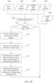
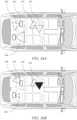
- a display apparatusfor use in a vehicle comprising: a directional display device arranged to display an image, the directional display device having an angular output light distribution that is variable; and a control system arranged to vary the angular output light distribution of the directional display device on the basis of the output of a vehicle sensor system provided on the vehicle, wherein the vehicle sensor system comprises a darkness sensor system arranged to detect dark ambient conditions, the control system being arranged to angularly restrict the angular output light distribution of the directional display device on the basis of the output of the darkness sensor system indicating that dark ambient conditions have been detected.
- the display apparatusmay achieve reduced stray light reaching the driver for operation in low light conditions, for example during night driving.
- Display areamay be increased in comparison to conventional backlights, while providing an equivalent amount of stray light.
- Specular reflections of display imagesmay be reduced from glass areas such as the side windows or windshield, and display light falling onto vehicle surfaces such as upholstery or headlining may be reduced in illuminance.
- the vehicle sensor systemmay further comprise a gaze sensor system arranged to detect the gaze of an occupant of the vehicle, and the control system may be arranged to angularly expand the angular output light distribution of the directional display device on the basis of the output of the gaze sensor system indicating that the occupant's gaze is directed at the directional display device.
- a gaze sensor systemarranged to detect the gaze of an occupant of the vehicle
- the control systemmay be arranged to angularly expand the angular output light distribution of the directional display device on the basis of the output of the gaze sensor system indicating that the occupant's gaze is directed at the directional display device.
- the function and content of some of the vehicle displaycan be directed to passengers with the same display showing a content to the driver only when looked at by the driver. The amount of distracting light to the driver is reduced.
- the control systemmay be further arranged to decrease the brightness of the directional display device and/or adapt the color balance of the directional display device for viewing in dark ambient conditions on the basis of the output of the darkness sensor system indicating that dark ambient conditions have been detected.
- the vehicle sensor systemmay further comprise a brightness sensor system arranged to detect bright ambient conditions, and the control system may be arranged to restrict the angular output light distribution of the directional display device on the basis of the output of the brightness sensor system indicating that bright ambient conditions have been detected.
- the viewability of the vehicle displaysmay be improved for the driver in bright ambient conditions without increasing the overall power consumption over that of a conventional backlight.
- Advantageously reduced power consumptionmay extend the operating time of the vehicle or reduce the alternator load on the vehicle, improving its efficiency.
- the control systemmay be further arranged to increase the brightness of the directional display device and/or adapt the color balance of the directional display device for viewing in bright ambient conditions on the basis of the output of the darkness sensor system indicating that bright ambient conditions have been detected.
- the vehicle sensor systemmay further comprise a vehicle motion sensor system arranged to detect motion of the vehicle, and the control system may be arranged to expand the angular output light distribution of the directional display device on the basis of the output of the vehicle motion sensor system indicating that the vehicle is motionless for a specified time.
- the driver and passengermay enjoy entertainment or other content from built-in vehicle displays when the vehicle is parked or in stationary traffic.
- the vehicle sensor systemmay further comprise an occupant sensor system arranged to recognize an occupant of the vehicle, and the control system may be arranged to direct the angular output light distribution of the directional display device towards an occupant on the basis of the output of the occupant sensor system.
- control systemcan be arranged to recognize the driver and link his portable device, for example a phone device, to the view seen by the driver.
- the passenger's phone devicemay be automatically linked to the passenger view.
- the display apparatusmay further comprise an orientation sensor arranged to detect the orientation of the directional display device and the control system may be arranged to vary the angular output light distribution of the directional display device on the basis of the output of the orientation sensor.
- the portable directional-display-capable phones, tablets and devices of passengersmay be arranged to avoid or reduce reflections from vehicle glass areas that can be visible or distracting to the driver.
- the orientation sensormay comprise an inertial sensor.
- Advantageously inertial sensorsmay respond to the movement of a portable device with relatively low lag or latency compared to that of a camera image that is subsequently processed.
- the orientation sensormay comprise a camera system and an analysis system arranged to detect the position of windows or glass areas of the vehicle in images captured by the camera system.
- a camera systemmay not be subject to the drift or integrated error that may accumulate in an inertial sensor system.
- Advantageously use of inertial and camera systemscan improve the overall performance of the glass reflection prediction system and reduce driver distracting reflections.
- the directional display devicemay be mounted to the vehicle or built-in to the vehicle.
- the directional display devicemay be mounted to the central console of the vehicle.
- the directional display devicemay be arranged to display an image captured by an image capture system such as a camera facing rearward (rearwardly) of the vehicle.
- an image capture systemsuch as a camera facing rearward (rearwardly) of the vehicle.
- the directional output of synthetic mirror displaysdisplays which emulate the function of conventional vehicle mirrors, may be controlled to avoid distracting reflections. Such displays may further brighten or change their output display direction when looked at by the driver reducing night time levels of stray light in the cabin.
- the directional display apparatusmay be a portable apparatus, the control system of the directional display apparatus being arranged to communicate with a processing system of the vehicle.
- the portable devices in the vehiclemay be requested or mandated to control their directional output and brightness to avoid distracting specular reflections visible to the driver or to reduce the levels of ambient light in the vehicle at night time.
- the processing system of the vehiclemay be arranged to communicate vehicle internal layout or geometry information to the control system of the directional display apparatus that identifies the internal layout of the vehicle, the control system may be arranged to vary the angular output light distribution of the directional display device on the basis of the layout information.
- the portable directional display devicesmay be able to receive the vehicle layout information including, for example, the position of glass areas or windows without having to calculate or model the likely positions of windows or glass.
- the communication with the processing system of the vehiclemay be wireless communication.
- the portable directional display devicesdo not need to be physically wired to the vehicle to receive information about the vehicle.
- the display apparatus control systemmay be arranged to vary the angular output light distribution of the directional display device in a manner that may reduce the incidence of light on windows of the vehicle.
- the distracting effect of light reflected in glass on the driveris reduced.
- the visibility of objects outside the vehicle through the glass surfacesis improved.
- the display apparatus control systemmay also be arranged to vary at least one of the brightness, contrast, color balance and content of the image displayed on the directional display device.
- the directional display devicemay comprise: a directional backlight arranged to direct light into selectable viewing windows; and may further comprise a spatial light modulator arranged to modulate the light output by the directional backlight, wherein the control system may be arranged to vary the angular output light distribution of the directional display device by selecting the viewing windows into which light is directed.
- the passenger and drivermay see images without undue distraction to the driver or high levels of background illumination within the vehicle cabin or distracting window or glass surface reflections.
- the directional backlightmay comprise: an array of light sources; and a directional waveguide arranged to direct light from each light source into a respective viewing window, wherein the control system may be arranged to vary the angular output light distribution of the directional display device by selecting which light sources are operated.
- the directional waveguidemay comprise: first and second opposed guide surfaces for guiding input light from the light sources along the waveguide; and a reflective end for reflecting input light back along the waveguide, wherein the second guide surface may be arranged to deflect light reflected from the reflective end through the first guide surface as output light.
- the first guide surfacemay be arranged to guide light by total internal reflection and the second guide surface may comprise a plurality of light extraction features oriented to direct light reflected by the reflected end in directions allowing exit through the first guide surface as the output light and intermediate regions between the light extraction features that are arranged to guide light along the waveguide.
- Embodiments hereinmay provide an autostereoscopic display that provides wide angle viewing which may allow for directional viewing and conventional 2D compatibility.
- the wide angle viewing modemay be for observer tracked autostereoscopic 3D display, observer tracked 2D display (for example for privacy or power saving applications), for wide viewing angle 2D display or for wide viewing angle stereoscopic 3D display.
- embodimentsmay provide a controlled illuminator for the purposes of an efficient autostereoscopic display.
- Such componentscan be used in directional backlights, to provide directional displays including autostereoscopic displays.
- embodimentsmay relate to a directional backlight apparatus and a directional display which may incorporate the directional backlight apparatus.
- Such an apparatusmay be used for autostereoscopic displays, privacy displays, multi-user displays and other directional display applications that may achieve, for example, power savings operation and/or high luminance operation.
- Embodiments hereinmay provide an autostereoscopic display with large area and thin structure. Further, as will be described, the optical valves of the present disclosure may achieve thin optical components with large back working distances. Such components can be used in directional backlights, to provide directional displays including autostereoscopic displays. Further, embodiments may provide a controlled illuminator for the purposes of an efficient autostereoscopic display.
- Embodiments of the present disclosuremay be used in a variety of optical systems.
- the embodimentsmay include or work with a variety of projectors, projection systems, optical components, displays, microdisplays, computer systems, processors, self-contained projector systems, visual and/or audiovisual systems and electrical and/or optical devices.
- aspects of the present disclosuremay be used with practically any apparatus related to optical and electrical devices, optical systems, presentation systems or any apparatus that may contain any type of optical system. Accordingly, embodiments of the present disclosure may be employed in optical systems, devices used in visual and/or optical presentations, visual peripherals and so on and in a number of computing environments.
- Directional backlightsoffer control over the illumination emanating from substantially the entire output surface controlled typically through modulation of independent LED light sources arranged at the input aperture side of an optical waveguide. Controlling the emitted light directional distribution can achieve single person viewing for a security function, where the display can only be seen by a single viewer from a limited range of angles; high electrical efficiency, where illumination is primarily provided over a small angular directional distribution; alternating left and right eye viewing for time sequential stereoscopic and autostereoscopic display; and low cost.
- Time multiplexed autostereoscopic displayscan advantageously improve the spatial resolution of autostereoscopic display by directing light from all of the pixels of a spatial light modulator to a first viewing window in a first time slot, and all of the pixels to a second viewing window in a second time slot.
- Time multiplexed displayscan advantageously achieve directional illumination by directing an illuminator array through a substantially transparent time multiplexed spatial light modulator using directional optical elements, wherein the directional optical elements substantially form an image of the illuminator array in the window plane.
- the uniformity of the viewing windowsmay be advantageously independent of the arrangement of pixels in the spatial light modulator.
- Such displayscan provide observer tracking displays which have low flicker, with low levels of cross talk for a moving observer.
- the illuminator elements of the time sequential illumination systemmay be provided, for example, by pixels of a spatial light modulator with size approximately 100 micrometers in combination with a lens array.
- pixelssuffer from similar difficulties as for spatially multiplexed displays. Further, such devices may have low efficiency and higher cost, requiring additional display components.
- High window plane uniformitycan be conveniently achieved with macroscopic illuminators, for example, an array of LEDs in combination with homogenizing and diffusing optical elements that are typically of size 1 mm or greater.
- the increased size of the illuminator elementsmeans that the size of the directional optical elements increases proportionately. For example, a 16 mm wide illuminator imaged to a 65 mm wide viewing window may require a 200 mm back working distance.
- the increased thickness of the optical elementscan prevent useful application, for example, to mobile displays, or large area displays.
- optical valves as described in commonly-owned U.S. Pat. Appl. No. 13/300,293advantageously can be arranged in combination with fast switching transmissive spatial light modulators to achieve time multiplexed autostereoscopic illumination in a thin package while providing high resolution images with flicker free observer tracking and low levels of cross talk.
- Describedis a one dimensional array of viewing positions, or windows, that can display different images in a first, typically horizontal, direction, but contain the same images when moving in a second, typically vertical, direction.
- imaging directional backlightsare arranged to direct the illumination from multiple light sources through a display panel to respective multiple viewing windows in at least one axis.
- Each viewing windowis substantially formed as an image in at least one axis of a light source by the imaging system of the imaging directional backlight.
- An imaging systemmay be formed between multiple light sources and the respective window images. In this manner, the light from each of the multiple light sources is substantially not visible for an observer's eye outside of the respective viewing window.
- Non-imaging backlightsare used for illumination of 2D displays. See, e.g., Kälil Käläntär et al., Backlight Unit With Double Surface Light Emission, J. Soc. Inf. Display, Vol. 12, Issue 4, pp. 379-387 (Dec. 2004 ).
- Non-imaging backlightsare typically arranged to direct the illumination from multiple light sources through a display panel into a substantially common viewing zone for each of the multiple light sources to achieve wide viewing angle and high display uniformity.
- non-imaging backlightsdo not form viewing windows. In this manner, the light from each of the multiple light sources may be visible for an observer's eye at substantially all positions across the viewing zone.
- Such conventional non-imaging backlightsmay have some directionality, for example, to increase screen gain compared to Lambertian illumination, which may be provided by brightness enhancement films such as BEF TM from 3M. However, such directionality may be substantially the same for each of the respective light sources. Thus, for these reasons and others that should be apparent to persons of ordinary skill, conventional non-imaging backlights are different to imaging directional backlights.
- Edge lit non-imaging backlight illumination structuresmay be used in liquid crystal display systems such as those seen in 2D Laptops, Monitors and TVs. Light propagates from the edge of a lossy waveguide which may include sparse features; typically local indentations in the surface of the guide which cause light to be lost regardless of the propagation direction of the light.
- an optical valveis an optical structure that may be a type of light guiding structure or device referred to as, for example, a light valve, an optical valve directional backlight, and a valve directional backlight ("v-DBL").
- optical valveis different to a spatial light modulator (even though spatial light modulators may be sometimes generally referred to as a "light valve” in the art).
- One example of an imaging directional backlightis an optical valve that may employ a folded optical system. Light may propagate substantially without loss in one direction through the optical valve, may be incident on an imaging reflector, and may counter-propagate such that the light may be extracted by reflection off tilted light extraction features, and directed to viewing windows as described in U.S. Pat. Appl. No. 13/300,293 (now U.S. Patent No. 9,519,153 ), which is herein incorporated by reference in its entirety.
- a stepped waveguide imaging directional backlightmay be at least one of an optical valve.
- a stepped waveguideis a waveguide for an imaging directional backlight comprising a waveguide for guiding light, further comprising: a first light guiding surface; and a second light guiding surface, opposite the first light guiding surface, further comprising a plurality of light guiding features interspersed with a plurality of extraction features arranged as steps.
- lightmay propagate within an exemplary optical valve in a first direction from an input side to a reflective side and may be transmitted substantially without loss.
- Lightmay be reflected at the reflective side and propagates in a second direction substantially opposite the first direction.
- the lightmay be incident on light extraction features, which are operable to redirect the light outside the optical valve.
- the optical valvegenerally allows light to propagate in the first direction and may allow light to be extracted while propagating in the second direction.
- the optical valvemay achieve time sequential directional illumination of large display areas. Additionally, optical elements may be employed that are thinner than the back working distance of the optical elements to direct light from macroscopic illuminators to a window plane. Such displays may use an array of light extraction features arranged to extract light counter propagating in a substantially parallel waveguide.
- Thin imaging directional backlight implementations for use with LCDshave been proposed and demonstrated by 3M, for example U.S. Patent No. 7,528,893 ; by Microsoft, for example U.S. Patent No. 7,970,246 which may be referred to herein as a "wedge type directional backlight;” by RealD, for example U.S. Pat. Appl. No. 13/300,293 (now U.S. Patent No. 9,519,153 ) which may be referred to herein as an "optical valve” or "optical valve directional backlight,” all of which are herein incorporated by reference in their entirety.
- the present disclosureprovides stepped waveguide imaging directional backlights in which light may reflect back and forth between the internal faces of, for example, a stepped waveguide which may include a first side and a first set of features. As the light travels along the length of the stepped waveguide, the light may not substantially change angle of incidence with respect to the first side and first set of surfaces and so may not reach the critical angle of the medium at these internal faces. Light extraction may be advantageously achieved by a second set of surfaces (the step “risers") that are inclined to the first set of surfaces (the step "treads"). Note that the second set of surfaces may not be part of the light guiding operation of the stepped waveguide, but may be arranged to provide light extraction from the structure.
- a wedge type imaging directional backlightmay allow light to guide within a wedge profiled waveguide having continuous internal surfaces. The optical valve is thus not a wedge type imaging directional backlight.
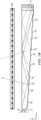
- FIGURE 1Ais a schematic diagram illustrating a front view of light propagation in one embodiment of a directional display device
- FIGURE 1Bis a schematic diagram illustrating a side view of light propagation in the directional display device of FIGURE 1A .
- FIGURE 1Aillustrates a front view in the xy plane of a directional backlight of a directional display device, and includes an illuminator array 15 which may be used to illuminate a stepped waveguide 1.
- Illuminator array 15includes illuminator elements 15a through illuminator element 15n (where n is an integer greater than one).
- the stepped waveguide 1 of FIGURE 1Amay be a stepped, display sized waveguide 1.
- Illumination elements 15a through 15nare light sources that may be light emitting diodes (LEDs).
- FIGURE 1Billustrates a side view in the xz plane, and includes illuminator array 15, SLM 48, extraction features 12, guiding features 10, and stepped waveguide 1, arranged as shown.
- the side view provided in FIGURE 1Bis an alternative view of the front view shown in FIGURE 1A . Accordingly, the illuminator array 15 of FIGURES 1A and 1B corresponds to one another and the stepped waveguide 1 of FIGURES 1A and 1B may correspond to one another.
- the stepped waveguide 1may have an input end 2 that is thin and a reflective end 4 that is thick.
- the waveguide 1extends between the input end 2 that receives input light and the reflective end 4 that reflects the input light back through the waveguide 1.
- the length of the input end 2 in a lateral direction across the waveguideis greater than the height of the input end 2.
- the illuminator elements 15a - 15nare disposed at different input positions in a lateral direction across the input end 2.
- the waveguide 1has first and second, opposed guide surfaces extending between the input end 2 and the reflective end 4 for guiding light forwards and back along the waveguide 1.
- the second guide surfacehas a plurality of light extraction features 12 facing the reflective end 4 and arranged to reflect at least some of the light guided back through the waveguide 1 from the reflective end from different input positions across the input end in different directions through the first guide surface that are dependent on the input position.
- the light extraction features 12are reflective facets, although other reflective features could be used.
- the light extraction features 12do not guide light through the waveguide, whereas the intermediate regions of the second guide surface intermediate the light extraction features 12 guide light without extracting it. Those regions of the second guide surface are planar and may extend parallel to the first guide surface, or at a relatively low inclination.
- the light extraction features 12extend laterally to those regions so that the second guide surface has a stepped shape which may include the light extraction features 12 and intermediate regions.
- the light extraction features 12are oriented to reflect light from the light sources, after reflection from the reflective end 4, through the first guide surface.
- the light extraction features 12are arranged to direct input light from different input positions in the lateral direction across the input end in different directions relative to the first guide surface that are dependent on the input position.
- the illumination elements 15a-15nare arranged at different input positions, the light from respective illumination elements 15a-15n is reflected in those different directions.
- each of the illumination elements 15a-15ndirects light into a respective optical window in output directions distributed in the lateral direction in dependence on the input positions.
- the lateral direction across the input end 2 in which the input positions are distributedcorresponds with regard to the output light to a lateral direction to the normal to the first guide surface.
- the illuminator elements 15a - 15nmay be selectively operated to direct light into a selectable optical window.
- the optical windowsmay be used individually or in groups as viewing windows.
- the SLM 48extends across the waveguide and modulates the light output therefrom.
- the SLM 48may be a liquid crystal display (LCD), this is merely by way of example and other spatial light modulators or displays may be used including LCOS, DLP devices, and so forth, as this illuminator may work in reflection.
- the SLM 48is disposed across the first guide surface of the waveguide and modulates the light output through the first guide surface after reflection from the light extraction features 12.
- FIGURE 1AThe operation of a directional display device that may provide a one dimensional array of viewing windows is illustrated in front view in FIGURE 1A , with its side profile shown in FIGURE 1B .
- the lightmay propagate along +x in a first direction, within the stepped waveguide 1, while at the same time, the light may fan out in the xy plane and upon reaching the far curved end side 4, may substantially or entirely fill the curved end side 4.
- the lightWhile propagating, the light may spread out to a set of angles in the xz plane up to, but not exceeding the critical angle of the guide material.
- the extraction features 12 that link the guiding features 10 of the bottom side of the stepped waveguide 1may have a tilt angle greater than the critical angle and hence may be missed by substantially all light propagating along +x in the first direction, ensuring the substantially lossless forward propagation.
- the curved end side 4 of the stepped waveguide 1may be made reflective, typically by being coated with a reflective material such as, for example, silver, although other reflective techniques may be employed.
- Lightmay therefore be redirected in a second direction, back down the guide in the direction of - x and may be substantially collimated in the xy or display plane.
- the angular spreadmay be substantially preserved in the xz plane about the principal propagation direction, which may allow light to hit the riser edges and reflect out of the guide.
- lightmay be effectively directed approximately normal to the xy display plane with the xz angular spread substantially maintained relative to the propagation direction. This angular spread may be increased when light exits the stepped waveguide 1 through refraction, but may be decreased somewhat dependent on the reflective properties of the extraction features 12.
- reflectionmay be reduced when total internal reflection (TIR) fails, squeezing the xz angular profile and shifting off normal.
- TIRtotal internal reflection
- the increased angular spread and central normal directionmay be preserved.
- lightmay exit the stepped waveguide 1 approximately collimated and may be directed off normal in proportion to the y-position of the respective illuminator element 15a - 15n in illuminator array 15 from the input edge center. Having independent illuminator elements 15a - 15n along the input edge 2 then enables light to exit from the entire first light directing side 6 and propagate at different external angles, as illustrated in FIGURE 1A .
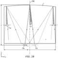
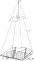
- Illuminating a spatial light modulator (SLM) 48 such as a fast liquid crystal display (LCD) panel with such a devicemay achieve autostereoscopic 3D as shown in top view or yz- plane viewed from the illuminator array 15 end in FIGURE 2A , front view in FIGURE 2B and side view in FIGURE 2C .
- FIGURE 2Ais a schematic diagram illustrating in a top view, propagation of light in a directional display device
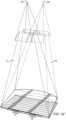
- FIGURE 2Bis a schematic diagram illustrating in a front view, propagation of light in a directional display device
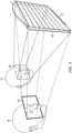
- FIGURE 2Cis a schematic diagram illustrating in side view propagation of light in a directional display device.
- a stepped waveguide 1may be located behind a fast (e.g., greater than 100Hz) LCD panel SLM 48 that displays sequential right and left eye images.
- a faste.g., greater than 100Hz
- specific illuminator elements 15a through 15n of illuminator array 15may be selectively turned on and off, providing illuminating light that enters right and left eyes substantially independently by virtue of the system's directionality.
- sets of illuminator elements of illuminator array 15are turned on together, providing a one dimensional viewing window 26 or an optical pupil with limited width in the horizontal direction, but extended in the vertical direction, in which both eyes horizontally separated may view a left eye image, and another viewing window 44 in which a right eye image may primarily be viewed by both eyes, and a central position in which both the eyes may view different images.
- 3Dmay be viewed when the head of a viewer is approximately centrally aligned. Movement to the side away from the central position may result in the scene collapsing onto a 2D image.
- the reflective end 4may have positive optical power in the lateral direction across the waveguide.
- the optical axismay be defined with reference to the shape of the reflective end 4, for example being a line that passes through the center of curvature of the reflective end 4 and coincides with the axis of reflective symmetry of the end 4 about the x-axis.
- the optical axismay be similarly defined with respect to other components having optical power, for example the light extraction features 12 if they are curved, or the Fresnel lens 62 described below.
- the optical axis 238is typically coincident with the mechanical axis of the waveguide 1.
- the optical axis 238is a line that passes through the center of curvature of the surface at end 4 and coincides with the axis of reflective symmetry of the side 4 about the x-axis.
- the optical axis 238is typically coincident with the mechanical axis of the waveguide 1.
- the cylindrical reflecting surface at end 4may typically comprise a spherical profile to optimize performance for on-axis and off-axis viewing positions. Other profiles may be used.
- FIGURE 3is a schematic diagram illustrating in side view a directional display device. Further, FIGURE 3 illustrates additional detail of a side view of the operation of a stepped waveguide 1, which may be a transparent material.
- the stepped waveguide 1may include an illuminator input side 2, a reflective side 4, a first light directing side 6 which may be substantially planar, and a second light directing side 8 which includes guiding features 10 and light extraction features 12.
- light rays 16 from an illuminator element 15c of an illuminator array 15may be guided in the stepped waveguide 1 by means of total internal reflection by the first light directing side 6 and total internal reflection by the guiding feature 10, to the reflective side 4, which may be a mirrored surface.
- reflective side 4may be a mirrored surface and may reflect light, it may in some embodiments also be possible for light to pass through reflective side 4.
- light ray 18 reflected by the reflective side 4may be further guided in the stepped waveguide 1 by total internal reflection at the reflective side 4 and may be reflected by extraction features 12.
- Light rays 18 that are incident on extraction features 12may be substantially deflected away from guiding modes of the stepped waveguide 1 and may be directed, as shown by ray 20, through the side 6 to an optical pupil that may form a viewing window 26 of an autostereoscopic display.
- the width of the viewing window 26may be determined by at least the size of the illuminator, output design distance and optical power in the side 4 and extraction features 12.
- the height of the viewing windowmay be primarily determined by the reflection cone angle of the extraction features 12 and the illumination cone angle input at the input side 2.
- each viewing window 26represents a range of separate output directions with respect to the surface normal direction of the spatial light modulator 48 that intersect with a plane at the nominal viewing distance.
- FIGURE 4Ais a schematic diagram illustrating in front view a directional display device which may be illuminated by a first illuminator element and including curved light extraction features. Further, FIGURE 4A shows in front view further guiding of light rays from illuminator element 15c of illuminator array 15, in the stepped waveguide 1. Each of the output rays are directed towards the same viewing window 26 from the respective illuminator 14. Thus light ray 30 may intersect the ray 20 in the window 26, or may have a different height in the window as shown by ray 32. Additionally, in various embodiments, sides 22, 24 of the waveguide 1 may be transparent, mirrored, or blackened surfaces.
- light extraction features 12may be elongate, and the orientation of light extraction features 12 in a first region 34 of the light directing side 8 (light directing side 8 shown in FIGURE 3 , but not shown in FIGURE 4A ) may be different to the orientation of light extraction features 12 in a second region 36 of the light directing side 8.
- FIGURE 4Bis a schematic diagram illustrating in front view an optical valve which may be illuminated by a second illuminator element. Further, FIGURE 4B shows the light rays 40, 42 from a second illuminator element 15h of the illuminator array 15. The curvature of the reflective end on the side 4 and the light extraction features 12 cooperatively produce a second viewing window 44 laterally separated from the viewing window 26 with light rays from the illuminator element 15h.
- the arrangement illustrated in FIGURE 4Bmay provide a real image of the illuminator element 15c at a viewing window 26 in which the real image may be formed by cooperation of optical power in reflective side 4 and optical power which may arise from different orientations of elongate light extraction features 12 between regions 34 and 36, as shown in FIGURE 4A .
- the arrangement of FIGURE 4Bmay achieve improved aberrations of the imaging of illuminator element 15c to lateral positions in viewing window 26. Improved aberrations may achieve an extended viewing freedom for an autostereoscopic display while achieving low cross talk levels.
- FIGURE 5is a schematic diagram illustrating in front view an embodiment of a directional display device having substantially linear light extraction features. Further, FIGURE 5 shows a similar arrangement of components to FIGURE 1 (with corresponding elements being similar), with one of the differences being that the light extraction features 12 are substantially linear and parallel to each other. Advantageously, such an arrangement may provide substantially uniform illumination across a display surface and may be more convenient to manufacture than the curved extraction features of FIGURE 4A and FIGURE 4B .
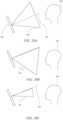
- FIGURE 6Ais a schematic diagram illustrating one embodiment of the generation of a first viewing window in a time multiplexed imaging directional display device in a first time slot
- FIGURE 6Bis a schematic diagram illustrating another embodiment of the generation of a second viewing window in a time multiplexed imaging directional backlight apparatus in a second time slot
- FIGURE 6Cis a schematic diagram illustrating another embodiment of the generation of a first and a second viewing window in a time multiplexed imaging directional display device.
- FIGURE 6Ashows schematically the generation of illumination window 26 from stepped waveguide 1.
- Illuminator element group 31 in illuminator array 15may provide a light cone 17 directed towards a viewing window 26.
- FIGURE 6Bshows schematically the generation of illumination window 44.
- Illuminator element group 33 in illuminator array 15may provide a light cone 19 directed towards viewing window 44.
- windows 26 and 44may be provided in sequence as shown in FIGURE 6C . If the image on a spatial light modulator 48 (not shown in FIGURES 6A , 6B , 6C ) is adjusted in correspondence with the light direction output, then an autostereoscopic image may be achieved for a suitably placed viewer. Similar operation can be achieved with all the directional backlights described herein.
- illuminator element groups 31, 33each include one or more illumination elements from illumination elements 15a to 15n, where n is an integer greater than one.
- FIGURE 7is a schematic diagram illustrating one embodiment of an observer tracking autostereoscopic directional display device. As shown in FIGURE 7 , selectively turning on and off illuminator elements 15a to 15n along axis 29 provides for directional control of viewing windows.
- the head 45 positionmay be monitored with a camera, motion sensor, motion detector, or any other appropriate optical, mechanical or electrical means, and the appropriate illuminator elements of illuminator array 15 may be turned on and off to provide substantially independent images to each eye irrespective of the head 45 position.
- the head tracking systemmay provide monitoring of more than one head 45, 47 (head 47 not shown in FIGURE 7 ) and may supply the same left and right eye images to each viewers' left and right eyes providing 3D to all viewers. Again similar operation can be achieved with all the directional backlights described herein.
- FIGURE 8is a schematic diagram illustrating one embodiment of a multi-viewer directional display device as an example including an imaging directional backlight.
- at least two 2D imagesmay be directed towards a pair of viewers 45, 47 so that each viewer may watch a different image on the spatial light modulator 48.
- the two 2D images of FIGURE 8may be generated in a similar manner as described with respect to FIGURE 7 in that the two images would be displayed in sequence and in synchronization with sources whose light is directed toward the two viewers.
- One imageis presented on the spatial light modulator 48 in a first phase
- a second imageis presented on the spatial light modulator 48 in a second phase different from the first phase.
- the output illuminationis adjusted to provide first and second viewing windows 26, 44 respectively. An observer with both eyes in window 26 will perceive a first image while an observer with both eyes in window 44 will perceive a second image.
- FIGURE 9is a schematic diagram illustrating a privacy directional display device which includes an imaging directional backlight.
- 2D display systemsmay also utilize directional backlighting for security and efficiency purposes in which light may be primarily directed at the eyes of a first viewer 45 as shown in FIGURE 9 .
- first viewer 45may be able to view an image on device 50
- lightis not directed towards second viewer 47.
- second viewer 47is prevented from viewing an image on device 50.
- Each of the embodiments of the present disclosuremay advantageously provide autostereoscopic, dual image or privacy display functions.
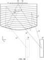
- FIGURE 10is a schematic diagram illustrating in side view the structure of a time multiplexed directional display device as an example including an imaging directional backlight. Further, FIGURE 10 shows in side view an autostereoscopic directional display device, which may include the stepped waveguide 1 and a Fresnel lens 62 arranged to provide the viewing window 26 in a window plane 106 at a nominal viewing distance from the spatial light modulator for a substantially collimated output across the stepped waveguide 1 output surface. A vertical diffuser 68 may be arranged to extend the height of the window 26 further. The light may then be imaged through the spatial light modulator 48.
- an autostereoscopic directional display devicewhich may include the stepped waveguide 1 and a Fresnel lens 62 arranged to provide the viewing window 26 in a window plane 106 at a nominal viewing distance from the spatial light modulator for a substantially collimated output across the stepped waveguide 1 output surface.
- a vertical diffuser 68may be arranged to extend the height of the window 26 further
- the illuminator array 15may include light emitting diodes (LEDs) that may, for example, be phosphor converted blue LEDs, or may be separate RGB LEDs.
- the illuminator elements in illuminator array 15may include a uniform light source and spatial light modulator arranged to provide separate illumination regions.
- the illuminator elementsmay include laser light source(s).
- the laser outputmay be directed onto a diffuser by means of scanning, for example, using a galvo or MEMS scanner.
- laser lightmay thus be used to provide the appropriate illuminator elements in illuminator array 15 to provide a substantially uniform light source with the appropriate output angle, and further to provide reduction in speckle.
- the illuminator array 15may be an array of laser light emitting elements.
- the diffusermay be a wavelength converting phosphor, so that illumination may be at a different wavelength to the visible output light.
- a further wedge type directional backlightis generally discussed by U.S. Patent No. 7,660,047 which is herein incorporated by reference in its entirety.
- the wedge type directional backlight and optical valvefurther process light beams in different ways.
- light input at an appropriate anglewill output at a defined position on a major surface, but light rays will exit at substantially the same angle and substantially parallel to the major surface.
- light input to a stepped waveguide of an optical valve at a certain anglemay output from points across the first side, with output angle determined by input angle.
- the stepped waveguide of the optical valvemay not require further light re-direction films to extract light towards an observer and angular non-uniformities of input may not provide non-uniformities across the display surface.
- waveguides, directional backlights and directional display devicesthat are based on and incorporate the structures of FIGURES 1 to 10 above. Except for the modifications and/or additional features which will now be described, the above description applies equally to the following waveguides, directional backlights and display devices, but for brevity will not be repeated.
- the waveguides described belowmay be incorporated into a directional backlight or a directional display device as described above.
- the directional backlights described belowmay be incorporated into a directional display device as described above.
- FIGURE 11is a schematic diagram illustrating a directional display apparatus comprising a directional display device and a control system.
- the arrangement and operation of the control systemwill now be described and may be applied, with changes as necessary, to each of the display devices disclosed herein.
- the directional backlightcomprises a waveguide 1 and an array 15 of illumination elements 15a-15n arranged as described above.
- the control systemis arranged to selectively operate the illumination elements 15a-15n to direct light into selectable viewing windows.
- Fresnel lens 62may be arranged to cooperate with reflective end 4 to achieve viewing windows at a viewing plane.
- Transmissive spatial light modulator 48may be arranged to receive the light from the directional backlight. The image displayed on the SLM 48 may be presented in synchronization with the illumination of the light sources of the array 15.
- the control systemmay comprise a sensor system arranged to detect the position of the observer 99 relative to the display device 100.
- the sensor systemcomprises a position sensor 70, such as a camera arranged to determine the position of an observer 99; and a head position measurement system 72 that may for example comprise a computer vision image processing system.
- the position sensor 70may comprise known sensors including those comprising cameras and image processing units arranged to detect the position of observer faces.
- Position sensor 70may further comprise a stereo sensor arranged to improve the measure of longitudinal position compared to a monoscopic camera.
- position sensor 70may comprise measurement of eye spacing to give a measure of required placement of respective arrays of viewing windows from tiles of the directional display.
- the control systemmay further comprise an illumination controller 74 and an image controller 76 that are both supplied with the detected position of the observer supplied from the head position measurement system 72.
- the illumination controller 74comprises an LED controller arranged to determine which light sources of array 15 should be switched to direct light to respective eyes of observer 99 in cooperation with waveguide 1; and an LED driver arranged to control the operation of light sources of light source array 15 by means of drive lines.
- the illumination controller 74selects the illuminator elements 15 to be operated in dependence on the position of the observer 99 detected by the head position measurement system 72, so that the viewing windows 26 into which light is directed are in positions corresponding to the left and right eyes of the observer 99. In this manner, the lateral output directionality of the waveguide 1 corresponds with the observer position.
- the image controller 76is arranged to control the SLM 48 to display images.
- the image controller 76 and the illumination controller 74may operate as follows.
- the image controller 76controls the SLM 48 to display temporally multiplexed left and right eye images and the LED controller operates the light sources 15 to direct light into viewing windows in positions corresponding to the left and right eyes of an observer synchronously with the display of left and right eye images.
- an autostereoscopic effectis achieved using a time division multiplexing technique.
- a single viewing windowmay be illuminated by operation of a light source (which may comprise one or more LEDs) by means of a drive line wherein other drive lines are not driven as described elsewhere.
- the head position measurement system 72detects the position of an observer 99 relative to the display device 100.
- the LED controllerselects the light sources 15 to be operated in dependence on the position of the observer detected by the head position measurement system 72, so that the viewing windows into which light is directed are in positions corresponding to the left and right eyes of the observer.
- the output directionality of the waveguide 1may be achieved to correspond with the viewer position so that a first image may be directed to the observer's right eye in a first phase and directed to the observer's left eye in a second phase.
- FIGURE 12is a schematic diagram illustrating a side view of a directional display device with a rear reflector 300.
- the directional display devicemay include a directional backlight and a transmissive spatial light modulator.
- the rear reflector 300may include an array of reflective facets 310.
- the arrayis a linear array in that it repeats in a linear direction (e.g. vertically in FIGURE 12 ).
- Light rays 304 that are reflected from light extraction features 12 of the waveguide 1are directed to a vertical viewing position in the viewing window 26, with an angular distribution in the direction 320.
- light rays 306 that are transmitted through the features 12are lost to the system, or may interact with materials behind the display and scatter to produce undesirable cross talk between respective viewing windows.
- an optical windowrefers to the image of a single light source in the window plane.
- a viewing window 26is a region in the window plane 106 in which light is provided and which may include image data of substantially the same image from across the display area.
- a viewing windowmay be formed from multiple optical windows.
- the optical windowshave a small lateral extent (y-axis direction) and a large extent in a vertical direction orthogonal to the lateral extent (x-axis direction).
- light rays 306 that are transmitted through the features 12are incident on the reflective facets of rear reflector 300.
- the light rays 306are thus redirected towards the viewing window 26.
- the lateral extent and position of the respective optical windows for rays 304, 306is substantially the same; however the distribution of light in the vertical direction may be different for light ray bundles directed by reflection or transmission at features 12.
- a directional backlightmay thus include a waveguide and an array of light sources disposed at different input positions in a lateral direction across the input end of the waveguide.
- the waveguidemay have an input end, may include first and second opposed guide surfaces for guiding light along the waveguide, and a reflective end facing the input end for reflecting the input light back through the waveguide.
- the first guide surfacemay be arranged to guide light by total internal reflection and the second guide surface may have a stepped shape which may include a plurality of facets oriented to reflect light from the light sources, after reflection from the reflective end, through the first guide surface into optical windows in output directions.
- the output directionsmay be distributed in a lateral direction to the normal to the first guide surface in dependence on the input positions, and intermediate regions between the facets that are arranged to direct light through the waveguide without extracting it.
- the directional backlightmay also include a rear reflector which may include a linear array of reflective facets arranged to reflect light from the light sources that is transmitted through the plurality of facets of the waveguide, back through the waveguide to exit through the first guide surface into the optical windows.
- a directional display devicemay thus also include a directional backlight and a transmissive spatial light modulator arranged to receive the output light from the first guide surface.
- a display apparatusmay thus also include a directional display device, and a control system arranged to selectively operate the light sources to direct light into viewing windows corresponding to the output directions.
- the display apparatusmay be an autostereoscopic display apparatus in which the control system is further arranged to control the display device to display temporally multiplexed left and right images and synchronously to direct the displayed images into viewing windows in positions corresponding to left and right eyes of an observer.
- the control systemmay further include a sensor system arranged to detect the position of an observer across the display device.
- the control systemmay be arranged to direct the displayed images into viewing windows in positions corresponding to left and right eyes of an observer, in dependence on the detected position of the observer.
- the optical windows and viewing windows 26 achieved by the rays 304, 306may substantially overlap in the lateral direction.
- the cross talk of the displaymay be substantially maintained.
- the total intensity of light rays directed to viewing window 26may be increased and the display brightness may be increased.
- the battery lifetime of a mobile display devicemay be increased, and the cost and number of light sources may be reduced for a desired brightness level. Further cross talk from unwanted transmitted light through features 12 is reduced or eliminated.
- the reflector 300may be formed in a thin film that may be mounted in the case of a display system, thus minimizing cost and thickness.
- the structure of the reflector 300may be formed on a rear case of the backlight, for example by molding the structure of the reflector 300 as part of the display case and then coating with a metallization layer.
- thismay provide a stiff and flat structure, achieving high window quality for the viewing windows 26 that are reflected from the reflector 300.
- FIGURE 13is a schematic diagram illustrating in side view, the structure of a directional display device comprising a wedge directional backlight comprising a wedge waveguide 1104 with faceted mirror end 1102.
- the first guide surface 1105 of the waveguide 1104is arranged to guide light by total internal reflection and the second guide surface 1106 is substantially planar and inclined at an angle to direct light in directions that break the total internal reflection for outputting light through the first guide surface 1105.
- the display devicefurther comprises a deflection element 1108 extending across the first guide surface 1105 of the waveguide 1104 for deflecting light from array 1101 of light sources towards the normal to the first guide surface 1105.
- the waveguide 1104may further comprise a reflective end 1102 for reflecting input light back through the waveguide 1104, the second guide 1106 surface being arranged to deflect light as output light through the first guide surface 1105 after reflection from the reflective end 1102.
- the reflective endhas positive optical power in the lateral direction (y-axis) in a similar manner to the reflective end shown in FIGURE 5 for example. Further facets in the reflective end 1102 deflect the reflected light cones within the waveguide 1104 to achieve output coupling on the return path. Thus viewing windows are produced in a similar manner to that shown in FIGURE 8 .
- the directional displaymay comprise a spatial light modulator 1110 and parallax element 1100 aligned to the spatial light modulator 1110 that is further arranged to provide optical windows.
- a control system 72 similar to that shown in FIGURE 11may be arranged to provide control of directional illumination providing viewing windows 26 and windows 109 from the parallax element and aligned spatial light modulator.
- a first guide surfacemay be arranged to guide light by total internal reflection and the second guide surface may be substantially planar and inclined at an angle to direct light in directions that break that total internal reflection for outputting light through the first guide surface, and the display device may further comprise a deflection element extending across the first guide surface of the waveguide for deflecting light towards the normal to the first guide surface.
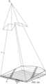
- FIGURE 14is a schematic diagram illustrating in perspective view, the formation of an optical window by an optical valve.
- Light source 15emay be arranged to provide optical window 26e after propagation in the waveguide 1.
- Light source 15emay be arranged to the right of the optical axis 199 when viewed from the position of the optical window 26e.
- Further light source 17emay also be arranged to substantially illuminate optical window 26e.
- Void correcting light source 17eis to the left of the optical axis 199 when viewed from the front.
- optical aberrationswill create an overlap of optical windows 26a-n from sources 15a-n and sources 17a-n, 19a-n (on opposite side to 17a-n and not shown) that is not identical but similar. Illumination of multiple sources provides a final uniform illuminated waveguide with desirable angular and spatial uniformity characteristics.
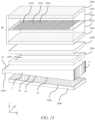
- FIGURE 15is a schematic diagram illustrating in side view, a directional display comprising a waveguide 1 arranged with a spatial light modulator 48.
- Reflective end 4may be provided by a Fresnel mirror.
- Taper region 2204may be arranged at the input to the waveguide 1 to increase input coupling efficiency from the light sources 15a-15n of the array of illuminator elements 15 and to increase illumination uniformity.
- Shading layer 2206 with aperture 2203may be arranged to hide light scattering regions at the edge of the waveguide 1.
- Rear reflector 2200may comprise facets 2202 that are curved and arranged to provide viewing windows 26 from groups of optical windows provided by imaging light sources of the array 15 to the window plane 106.
- Optical stack 2208may comprise reflective polarizers, retarder layers and diffusers.
- Rear reflectors 2200 and optical stack 2208are described further in U.S. Patent Appl. No. 14/186,862, filed February 21, 2014 , entitled "Directional backlight” ( U.S. Patent Publ. No. 2104-0240828 ; Attorney Ref. No. 355001) incorporated herein by reference in its entirety.
- Spatial light modulator 48may comprise a liquid crystal display that may comprise an input polarizer 2210, TFT glass substrate 2212, liquid crystal layer 2214, color filter glass substrate 2216 and output polarizer 2218.
- Red pixels 2220, green pixels 2222 and blue pixels 2224may be arranged in an array at the liquid crystal layer 2214.
- White, yellow, additional green or other color pixelsmay be further arranged in the liquid crystal layer to increase transmission efficiency, color gamut or perceived image resolution.
- injection of input light into the waveguideis along the long edge.
- the physical size of the LED packages of the array 15 and scatter from waveguide and other surfaces near the input end 2limit the minimum bezel width that can be achieved. It would be desirable to reduce the width of the side bezel along the long edges of the waveguide.
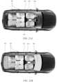
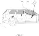
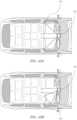
- FIGURE 16is a schematic diagram illustrating in side view, the location of displays in a vehicle cabin 401.
- Some displayssuch as 502 are mounted to or built-in to the vehicle 400. The output from such displays may be directed to the driver 504 but may also be visible in reflection 506 from the windshield 406.
- the cabin 401may also contain seat back displays 508 and portable phones 602 or tablet devices 604 that are not fixed to the vehicle but are "co-located”. With such displays in the vehicle 400, then the overall cabin 401 luminance and reflections from glass, for example 406, 404 and 402 can be both distracting for the driver at nighttime and the amount of blue and green light in the display output may impair the driver's night vision adaption, thereby reducing the safety of the vehicle operation.
- FIGURE 17is a schematic graph illustrating the luminance profile of a directional display in an axis orthogonal to the lateral direction (i.e. vertical). From the curve shown it can be seen that the luminance at +/- 45 degrees is about 20% of that at the peak brightness.
- FIGURE 18is a schematic diagram illustrating in side view reflections of light from a display from the windscreen or windshield (both terms are used in this specification) of a vehicle.
- the reflection of the light output at +/-45 degrees (510)may be about 8% so that for a display 502 with peak output in direction 504 of say 250 nits, then the light 511 reflected to the occupant 600 would be about 4 nits.
- FIGURES 19A-Bare schematic graphs illustrating angular profiles of light from a directional display with respect to occupants and vehicle windshield for portrait and landscape display orientations.
- FIGURE 19Ashows angular output light distribution of the directional display device in which the output light cone is controlled in the windshield direction so that in the region 702 indicated the angular space or angular cone of output light which is at 20% or more of the maximum output light 704.
- the angular spread in the horizontal directionmay be further electronically and dynamically controlled (e.g., reduced) as explained in other figures of this specification.
- FIGURE 19Bdiffers from FIGURE19A in that an angular output light distribution region 706 is produced in which the output light is at or above 20% of the intensity of the peak light output 708.
- the angular spread in the verticalmay be further controlled as explained in this specification
- FIGURES 20A-Care schematic diagrams illustrating in side view light cones from a directional display towards an occupant 600.
- a conventional display 502which may be an LCD, OLED or LED display, light may be emitted in the vertical direction as explained with reference to FIGURE 17 .
- the output from display 502is shown for illustrative purposes as illumination cone 522 representing the light output within for example +/- 45 degrees.
- the peak luminanceis in direction 520 normal to the display 502 and directed to occupant 600.
- FIGURE 20Bshows how the vertical angular output light distribution cone 524 may be tilted down so that the occupant 600 still sees the display but the windshield (not shown) reflections are reduced.
- FIGURE 20Cshows an illumination or angular output light distribution cone 526 that is both tilted down from the display normal 520 and narrowed.
- the narrow angular output light distribution conemaintains display visibility for the occupant 600 with reduced illumination of the footwell area and so may reduce the cabin background illumination, which helps avoid night time distractions and enables less power to be used by the display. Reducing the power of ancillary devices such as displays contributes to less demand on the vehicle alternator, increasing fuel efficiency, or for electric vehicles, extending the vehicle range.
- FIGURES 21A-Bare schematic diagrams illustrating in top view a typical vehicle cabin 401.
- the cabin 401may contain displays mounted to the vehicle such as the Driver Information Display (DID) or instrument cluster display (not labelled) for primary use of the driver in seat 424.
- the cabin 401may also contain portable personal devices such as phones, tablets or video players used by passengers for example in seats 420. All of these display have the potential to produce unwanted and distracting reflections in vehicle glass shown hatched in FIGURE 21B , for example 406, 402 and 422
- FIGURES 22A-Bare schematic diagrams illustrating in top view of a typical vehicle cabin 401 and respective angular output light distributions 536, 538 from a center stack directional display 532 in a first and second modes of operation.
- Automotive displaysmay differ from conventional mobile display applications in that they can be expected to provide clear readability for both very high illuminance conditions for example in bright sunlight and very low illuminance conditions such as at night time.
- daytime operationit would be desirable to increase display luminance without substantially increasing display power consumption.
- night time operationlight that is not directed to occupants' eyes can degrade the outside vision of the driver by means of (i) reflections of the display surface from windscreens and (ii) reflection from non-specular surfaces in the vehicle that provide a background illumination that may compete with externally illuminated objects, thus degrading driver night vision.
- the trend to fit both more and larger displays to vehicles coupled with the reduction in windshield angles (to improve aerodynamic efficiency)may all contribute to degraded driver outside vision.
- CSDCenter Stack Display
- center stack display 532may be arranged to provide angular output light distribution 536 with angular width illustrated as cone angular size 541 in direction 537 normal to the display 532.
- angular output light distributionssuch as 536 and 538 are used to show the extent of the angular illuminance output of displays (in this case CSD 532) at reference angles 541, 543 at which the display angular output drops to, for example, 20% of the peak illuminance output.
- the length of the angular output light distribution cones 536, 538represent the relative peak illuminance of display 532.
- the angular output light distribution 536is configured such that the display can conveniently be seen by driver, passenger and other occupants (not shown).
- angular output light distribution 538may be provided with direction 539, reduced cone angular size 543 and reduced illuminance. As illustrated, angular output light distribution 538 has a smaller length indicating lower display illuminance.
- the display 532may be switched automatically between first and second modes by means of signals from controller 534 which may also receive signals from vehicle sensors such as ambient light sensors and GPS position sensors and time clocks. Switching between modes may also be done under manual control.
- controller 534may also receive signals from vehicle sensors such as ambient light sensors and GPS position sensors and time clocks. Switching between modes may also be done under manual control.
- the total illuminance of the cabinincluding from specular surfaces such as glass windows 404, 406 and non-specular surfaces such as seats and headlining is reduced.
- the display power consumptionmay be reduced, increasing vehicle efficiency.
- the reflection from glass areas of cabin 401may be reduced.
- FIGURE 23is a schematic diagram illustrating in front view part of an automotive cabin. Light from display 502 may reach the occupant 600 both directly via path 1018 or may also reach the occupant 600 by reflection off side window glass 404 following path 1016, 1014.
- a directional display as described hereinwhich can alter the angular output angle can reduce side window reflections.
- Such a displaymay also adjust intensity and the image contrast of the images to reduce distracting reflections.
- FIGURES 24A-Care schematic diagrams illustrating in top view an automotive cabin and respective angular output light distribution from a passenger directional display in a first, second and third modes of operation.
- Modern vehiclesmay be fitted with large 17"-diagonal (or more) displays intended for passenger use.
- the angular output light distribution from these displaysis not intended for and may be required to be prevented from viewing by the driver.
- these large displayscan produce substantial reflections in side windows that are particularly distracting to the driver at night time.
- FIGURE 24Aillustrates a first mode of operation of the passenger specific display 540 in which it emits angular output light distribution 542 symmetrical with the passenger direction 544. In daylight operation the lower intensity at the side of the angular output light distribution towards the driver and the reflection at side window 546 may not be disturbing or distracting.
- FIGURE 24Billustrates a second mode of operation of the passenger specific display 540 for use where legislation or the driver requires that the display 540 is not visible to the driver at all. This may be achieved by tilting the angular output light distribution 548 from display 540 so that it tilts away from the driver. This has the side effect of potentially increasing the reflection at the side windows, however in bright sunlight or daylight this may not be distracting to the driver.
- FIGURE 24Cillustrates a third mode of operation of display 540 suitable for night time operation.
- the angular output light distribution 550 from display 540is narrowed so that no significant light falls on the side window glass and there is no visibility of the display directly by the driver.
- the angular output light distribution 550may be directed at the passenger and may also be reduced in intensity.
- the color temperature of the display white pointmay also be altered to a warmer color which humans find more comfortable for night time viewing.
- the display angular output light distribution coneis shown altered in direction and/or width in the horizontal direction, however the display cone may additionally be altered in the vertical direction as explained with reference to FIGURE 20A-C , in which case reflections from the windshield may be reduced or eliminated. Similarly diffuse reflection from upholstery may be reduced.
- the passengermay continue to use the display 540 at night time without disturbing the driver's night vision or producing distracting reflections.
- the display 540may not be required to be turned off at night time.
- the display 540may consume less power when emitting narrow angular output light distribution 550, which improves the electrical efficiency of the vehicle.
- FIGURES 25A-Bare schematic diagrams illustrating in top view an automotive cabin and respective angular output light distribution from further vehicle mounted directional displays in first and second modes of operation.
- the Driver Information Display(DID, 557) is frequently an electronic display and must be clearly visible in all lighting conditions including bright sunlight and at night time.
- Modern vehiclesmay now being provided with "synthetic" door mirror displays 556 which are embodied as electronic displays such as LCD panels placed internal to the vehicle and driven by signals that use data from small cameras or other sensors that provide outside views of the vehicle analogous to that provided by conventional wing or door mirrors. Not fitting bulky door mirrors can improve the aerodynamic efficiency of the vehicle and therefore also improve fuel efficiency or battery range.
- Such displaysare controllable to emit in angular output light distributions that vary according to driver commands and/or the operating environment including the light level exterior to the vehicle.
- FIGURE 25Aillustrates a first mode of operation where the Driver Instrument Display (DID 557) and synthetic mirror displays 556, 555 operate with angular output light distributions 552, 554 and 558. In bright sunlight or daylight the reflections produced by these displays in window glass may not be distracting given the level of outside or exterior illumination.
- FIGURE 25Billustrates a second mode of operation suitable for night time or low level outside illumination.
- the angular output light distribution 562 of the DID display 557is narrowed to reduce glass surface reflections.
- the angular output light distribution 564 of synthetic mirror display 556is also narrowed to reduce glass reflections.
- Synthetic mirror 555is shown with angular output light distribution 568 which may be in the same direction but is reduced in intensity compared to that of angular output light distribution 558 in FIGURE 25A .
- the intensity of light in angular output light distribution 562 and 564may also be reduced to match the driver's preference.
- Advantageously glass reflectionsare reduced.
- Advantageously background illumination in the cabin from upholstery, headlining or other contentsmay be reduced.
- Advantageously the driver's visual comfort level in high and low outside lighting levelmay be improved.
- Advantageously the smaller angular output light distributions 562, 564may consume less electrical power and therefore improve the vehicle efficiency.
- the vehiclemay also contain other displays such as seat back displays or passengers may be using smartphone and tablet displays. It would be desirable to provide a reduction of reflections from these portable mobile devices that are co-located to the vehicle. Reflections can be via glass surfaces to the eyes of a driver. Unlike the built in displays mounted to the vehicle the screens of these devices may be moveable or even be moving independently when in use.
- FIGURES 26A-Bare schematic diagrams illustrating in top view an automotive cabin and respective angular output light distribution from further portable directional displays in first and second modes of operation, further comprising display control communication means.
- FIGURE 26Aillustrates a first mode of operation suitable for daylight where seat back display 508 is emitting with angular output light distribution 576 and other passengers are using devices such as tablets 606, 608 emitting with angular output light distribution 570 and 572 and smartphone 610 emitting with angular output light distribution 574.
- the co-located portable mobile devicesmay be in communication with controller 534 by means of antenna 535 and communication protocols such as Bluetooth or WiFi. By this means the devices can be informed about the vehicle status, for example if it is in day mode or night mode. Setting to night mode may be dependent on the exterior illumination of the vehicle.
- FIGURE 26Billustrates a second mode of operation suitable for night time operation.
- the seat back display 508has reduced angle and brightness of angular output light distribution 586 and the co-located portable directional display devices are also operating at reduced brightness and angular output light distributions as indicated by angular output light distributions 580, 582, 584.
- Devices 606, 608, 508, 610may receive the instruction to enter the narrow angular output light distribution and low brightness second mode by means of controller 534 and antenna 535 and communication protocol such as Bluetooth or Wifi.
- the instruction to enter the second modemay be automatic or commanded by the driver.
- the brightness and angular emission of portable directional display devices in the cabinmay be reduced so that the display glass reflections are also reduced. Further, reflections from non-specular surfaces in the cabin may be reduced so that the background illumination level is maintained at a low level in order to preserve the driver's night vision adaptation.
- FIGURE 27is a flowchart illustrating directional illumination control of the displays mounted to the vehicle of FIGURE 24A-C and FIGURE 25A-C and the portable directional displays of FIGURES 26A-B for switching to a night mode of operation.
- the data sources available to the vehiclemay include the Date and Time (1060), the vehicle location and in particular the latitude derived from a Global Positioning System (GPS, 1062).
- GPSGlobal Positioning System
- the vehiclemay also have a darkness sensor system 1064 arranged to detect dark ambient conditions exterior to the vehicle.
- the vehiclemay also be capable of processing the commands from the driver by means of voice, gesture or the user interface of the vehicle such as buttons, dials, or a touch screen.
- These data sourcesmay be processed (1100) by the vehicle controller 534 in order to determine (1102) if the vehicle should request or command the directional displays mounted to the vehicle (e.g. 540 of FIGURE 24A-C ) and co-located portable directional displays ( FIGURE 26B 606, 608, 610 and 508) to switch to night mode.
- the displaysmay be requested to narrow or restrict their output light emission angle (1110), alter the screen colors and luminance for night mode (1112) and co-located portable devices (e.g. FIGURE 26B 606, 608, 610 and 508) may be requested to switch to night mode (1114), which may include changing colors, contrast, brightness and angular output light distribution cone width.
- the sensors available to the vehicle and internal processingmay enable the displays in the vehicle to enter night mode automatically or on the command of the driver, thereby improving the driver's visual comfort at night or in low light conditions such as at dusk or in underground car parks.
- FIGURE 28is a flowchart illustrating directional illumination control of the displays mounted to the vehicle of FIGURE 24A-C and FIGURE 25A-C and the portable directional displays of FIGURES 26A-B for a daytime mode of operation.
- the data sources available to the vehiclemay include the Date and Time (1060), the vehicle location and in particular the latitude derived from a Global Positioning System (GPS, 1062).
- GPSGlobal Positioning System
- the vehiclemay also have a darkness sensor 1064 arranged to detect bright or dark ambient conditions.
- the vehiclemay also be capable of processing the commands from the driver by means of voice, gesture or the user interface of the vehicle such as buttons, dials, or a touch screen.
- These data sourcesmay be processed (1100) by the vehicle controller 534 in order to determine (1104) if the vehicle should request or command the directional displays mounted to the vehicle (e.g. 540 of FIGURE 24A-C ) and co-located portable directional displays ( FIGURE 26B 606, 608, 610 and 508) to switch to day mode.
- the displaysmay be requested to derestrict their emission angle (1120), alter the screen colors and luminance for daylight mode (1122) and co-located portable devices (e.g. FIGURE 26B 606, 608, 610 and 508) may permitted to switch to day mode (1124), which may include changing colors, contrast, brightness and angular display angular output light distribution width.
- the convenience of the passengersis improved by enabling their displays to switch between driver sympathetic day and night modes without the need for user interaction or interruption of their work or entertainment.
- Vehicles that have rear facing seatsmay present additional glass reflection issues for the driver because rear facing seats have a short distance to the back window glass without an obscuring seat back. It would be desirable to reduce visibility of devices that are operated by rearwards facing occupants.
- FIGURES 29A-Bare schematic diagrams illustrating in top view an automotive cabin and respective angular output light distributions from further portable directional displays used by rear facing seat occupants in first and second modes of operation, further comprising display control communication means.
- FIGURE 29Aillustrates a first mode of operation where portable directional display 620 is operated by the occupant of a rear facing seat and produces angular output light distribution 588.
- the permission to operate in this first modemay be confirmed by communication with controller 534 by means of antenna 535 and by means of a wireless protocol such as Bluetooth or WiFi.
- a wireless protocolsuch as Bluetooth or WiFi.
- the angular output light distribution 588is shown in the horizontal plane but also extends in the vertical direction as explained with reference to FIGURE 17 and FIGURE 18 .
- FIGURE 29Billustrates a second mode of operation where the portable directional display 620 is operated by the occupant of a rear facing seat and produces angular output light distribution 590 with less angular spread and may also adopt reduced intensity.
- the instruction to operate in this second modemay be received by communication with controller 534 by means of antenna 535 and by means of a wireless protocol such as Bluetooth or WiFi.
- the power consumption of the portable directional display 620may also be reduced extending its operating time, or if operated using power supplied by the vehicle, reducing the load on the vehicle alternator or drain on the vehicle battery. Reducing the drain from the vehicle battery may be important for vehicles that are stationary such as in a traffic jam.
- FIGURE 30is a flowchart illustrating directional illumination control of the portable directional displays of FIGURES 26A-B and FIGURES 29A-B for a night time mode of operation where the vehicle communicates or broadcasts the internal layout of the vehicle including the layout position and shape or geometry of the vehicles glass areas (1068) and the driver's position to the portable directional displays.
- the portable directional displaysmay be arranged to restrict their angular output light distribution to minimize specular and diffuse reflections (1110). Further the portable directional displays may alter their colors and luminance (1112) to a night mode as described with reference to FIGURE 27 .
- the portable directional display devicesmay use the vehicle internal-layout information in conjunction with their own inertial sensors and optionally their own front or rearward (rearwardly) facing cameras (1114) to locate or predict reflections via glass surfaces. Responsive to that prediction the display angular output light distribution may be altered in angular direction or angular width, including altering the angular output angle to zero, i.e. off.
- the portable directional display devicesmay also use their inertial sensors and their cameras to predict reflections that will be distracting to the driver and may ignore reflections that the driver will not be able to see (1116). Responsive to that prediction the display angular output light distribution may be altered in angular direction or angular width, including altering the angular output angle to zero, i.e. off.
- Advantageously ray paths from a display to a driver by means of specular reflections from glass surfacesmay be calculated or predicted.
- Light that is directed to the drivermay be reduced by means of control of directionality in response to said calculated or predicted ray paths.
- FIGURES 31A-Care schematic diagrams illustrating in top view an automotive cabin and portable displays arranged to receive internal layout of the vehicle's including the location or shape of glass areas and the seat occupied by the driver in order to detect direct reflections from a glass surface to a driver.
- FIGURE 31Aillustrates the internal vehicle layout information being communicated from controller 534 by means of antenna 535 and a wireless protocol such as WiFi or Bluetooth to portable directional display device 622.
- the vehiclemay communicate its model type or serial number and the internal layout information may be accessed from a database internal to the portable directional display, or may be accessed from a database external to the vehicle, e.g. from a website.
- FIGURE 31Billustrates an example where portable directional display 622, having earlier received the internal layout information of the vehicle, is able to predict from its inertial sensors and or built in cameras that the currently selected angular output light distribution 596 will produce a disturbing reflection 594 in the direction of the driver.
- FIGURE 31Cillustrates display device 622 having detected or predicted a disturbing reflection, altering its angular output light distribution 598 such that reflections are in a new direction 595 which is not calculated to be disturbing for the driver.
- the display intensitymay also be reduced.
- the display output angular distribution anglemay be reduced to zero.
- Advantageously ray pathsmay be predicted and directionality adjusted, reducing unwanted visibility of displays and their reflections by the driver in night time driving and thereby increasing safety.
- FIGURE 32is a flowchart illustrating directional illumination control of the portable directional displays of FIGURES 26A-B for a night time mode of operation arranged to locate reflections from directional displays via glass surfaces to the eyes of a driver wherein the relative location of glass surfaces and driver location are detected by the respective portable directional display devices.
- the portable directional display devicescan calculate said ray paths with reduced vehicle input.
- the internal inertial sensorssuch as accelerometers and the built in cameras (1078) can cooperate to build up a model of the internal layout of the vehicle and the reflectance of surfaces. This can be done without the model type or name of the vehicle being known.
- the data captured by the portable display devicescan be compared to generic internal vehicle internal layout in order to determine the actual internal vehicle layout (1080) without having to rely on external databases or internal layout information supplied and communicated by the vehicle itself.
- Such datacan be captured in the background during daylight in order that the model can be prepared in advance of the need to switch to night mode.
- the internal layout informationcan be captured during night mode with the aid of cameras, inertial sensors and IR light sources built in to the personal directional display so that reflection data can be obtained at night without producing disturbing reflections to the driver.
- knowledge of the position (1202) of the personal devicecan be used in conjunction with the inertial sensors and cameras to predict movement and therefore also to predict disturbances from reflections (1024) to the driver.
- the predicted disturbancescan be used to determine a combination of display directional angle change or reduction including optionally dimming or even turning the display to emit over a zero angle (1206). If the angle of the display is reduced to zero when oriented to produce a disturbing reflection, the user will soon learn how to hold the device to avoid this.
- the low latency of inertial sensorscan provide accurate short term predictions of the portable display device position and orientation and the camera systems may provide longer term drift correction and identification of internal layout features such as glass, headlining upholstery and occupants. Thereby the disturbance to the driver may be minimized while allowing the other occupants to continue using their portable devices.
- FIGURES 33A-Care schematic diagrams illustrating in top view an automotive cabin and portable displays arranged to detect the internal layout of the vehicle in order to detect or predict direct reflections from a glass surface to a driver.
- FIGURE 33Adiffers from
- FIGURE 31Ain that the portable directional display device 622 can capture the location of specular and reflective surfaces in the vehicle autonomously and without needing internal layout information to be supplied by the vehicle controller 534 or other communication means.
- FIGURE 33Billustrates the light output distribution 596 creating a potential reflection disturbance in the direction of the driver 594.
- FIGURE 33Cillustrates how the output light distribution 598 may be modified to reduce or illuminate the reflective disturbance to the driver in direction 594.
- the vehiclemay still communicate to the portable directional display devices the instruction or request to enter the night mode where specular reflections and overall lighting disturbances from diffuse reflections are reduced.
- this methodcan also deal with "VARIABLES” such as passengers wearing light colored clothing or bags or temporary vehicle contents that are light colored or reflective. Therefore the reliability of the reflection disturbance reduction can be improved.
- Advantageously ray pathsmay be collected and directionality adjusted, reducing unwanted visibility of displays by the driver for night time driving and increasing safety.
- FIGURES 34A-Bare schematic diagrams illustrating in top view an automotive cabin and control of the directionality of portable directional mobile displays such that reflections from the display via a glass surface to a driver are minimized.
- Portable directional display device 624may autonomously alter its light output directional distribution from 626 where there is reflection from the back glass to the driver to output directional distribution 628 where there may be a window reflection, but this is not seen by or disturbing to the driver.
- the device 624may use its own darkness sensor system to indicate that dark ambient conditions have been detected, may use its own camera to recognize specular reflecting surfaces, may use its own processing to determine its location relative to the vehicle and the driver, and may use its own processing to determine if a disturbing reflection for the driver is predicted and take mitigating action.
- portable display device emitting angular light output distribution 640may detect similar conditions as device 622, but if it does not have a controllable directional display it may reduce its brightness to mitigate disturbance to the driver.
- Portable directional device 630may calculate that there is no direction in which it can adjust its angular directional output 632 without creating a disturbance for the driver. In which case the device may elect to turn its angular distribution angle to zero 638, effectively turning off the display. As soon as device 630 detects that it has been physically re-oriented so that a disturbing reflection is not likely then the display angular distribution angle may be reset to a non-zero angular width. It can be particularly problematic with emissive displays such as OLED and LED and LCD to maintain sufficient readability in very high ambient sunlight conditions or where there is a reflectance of the sun from the surface of the display directed directly at the driver.
- FIGURE 35is a schematic diagram illustrating in side view, reflection of sunlight from a directional display to an occupant in a vehicle cabin.
- the position of the sun 644 and the reflection paths 646 from displays mounted to the vehicle towards the driver's eyescan be calculated or predicted.
- the darkness sensor system built in to the vehiclemay also indicate that bright ambient conditions have been detected, i.e. it is not a cloudy or rainy day.
- FIGURES 36A-Bare schematic diagrams illustrating in top view an automotive cabin and control of the directionality of directional displays mounted to the vehicle in response to a bright ambient or prediction of a sunlight reflection from the display to the driver's eye line.
- FIGURE 36Ashows the normal daylight use angular output distributions 648, 650 from CSD directional display 532 mounted to the vehicle and passenger directional display 540 mounted to the vehicle.
- the drivermay see the output directional distribution indicated by angular output light distribution 652 where the light output in this narrower angular distribution may be increased over that of 648 without necessarily increasing the overall display power consumption of display 532.
- passenger directional display 540may alter its angular light output distribution from 650 to 654.
- Advantageously readability of the passenger directional display 540 and the CSD directional display 532are increased in high or very high ambient light conditions without requiring more power from the display backlight system.
- Advantageously concentrating the angular output from the displays 540, 532may reduce the drain on the vehicle battery or load on vehicle alternator. This may increase the efficiency of the vehicle.
- FIGURE 37is a flowchart illustrating angular output light distribution control of directional displays to provide a directional high luminance output in response to very high ambient light levels or reflection of bright external sources such as the sun by said directional display to a vehicle occupant.
- the vehiclemay process data (1100) from sensors including a darkness sensor system (1064) indicating that bright ambient conditions exist.
- the vehiclemay also process data (1100) from the date and time (1060) and latitude (1062) which may be derived from the GPS system.
- the drivermay choose to override (1066) sensor values to force the system to switch to high ambient Sunlight Mode (1104).
- the angular output of the directional displaysmay be narrowed and directed (1124) straight at the driver.
- the displaymay be brighter for the same power consumption as only a narrower range of angular space is illuminated.
- the angular output of the directional displaymay be adjusted in horizontal, vertical or both axes.
- the screen color choice and display contrast settingsmay be modified (1122) to enhance viewability and clarity in high ambient conditions.
- the display luminancemay be adjusted in response to the position of the reflections of direct sunlight from a display. Further advantageously the adjustment can be done for the driver's displays and or the passenger's display. Further advantageously the brightness of the directional display may be increased while minimizing the power needs of the backlight system and thereby increasing the battery range or efficiency of the vehicle.
- the CSD display 532because of the nature of the displayed information, may only require occasional or sporadic attention by the driver, and when the driver is not looking at this information the display may be optimized in angle and content for the passenger. In bright ambient conditions this means that the display produces only one super bright angular output light distribution at any one time but the directionality of this angular output varies in response to the gaze of the driver.
- FIGURE 38is a flowchart illustrating angular output illumination control of directional displays mounted to the vehicle to provide an increased luminance output in response to the location of reflection of bright external sources by said directional display to a vehicle occupant when said occupant is not looking directly at the display.
- Sunlight Mode(1070) is set or automatically selected, a camera built in to the vehicle and close to or in the display area may detect the gaze (1072) of the driver.
- Ambient light sensors (1064) and user override controls (1066)may be used to determine if (1106) the driver is looking at the display in high ambient or with the sun reflecting off the display.
- the angular output of directional displayssuch as the CSD 532 mounted to the vehicle (see FIGURE 39A ) may be moved (1130) to the driver's eyes.
- the screen colors, contrast and luminancemay be optimized for viewability in high ambient light (1132). Further the display content may be changed (1134) to a default view allowed to be viewed by the driver, or to that requested by the driver by, for example, voice commands, e.g. "show outside temperature", or "show oil temperature”. If the driver is not looking at the directional display such as the CSD 532, the angular output illumination direction may be moved (1136) to the passenger direction or a default direction.
- the screen colors, contrast and luminance (1138)may be optimized for high ambient light viewing suitable for the display content (1140) requested by the passenger.
- FIGURES 39A-Bare schematic diagrams illustrating in top view an automotive cabin and control of the directionality of directional display CSD 532 mounted to the vehicle in response to driver 658 gaze direction.
- the driver's gazemay be detected by means of a camera 664 and when looking at CSD 532 the angular output light distribution 656 along with content and brightness, display image contrast may be optimized for the driver in high ambient light or sunlight reflecting conditions.
- the driver's gazemay be detected by means of camera 664 and when looking away from the CSD 532 the angular output illumination direction 660 along with content and brightness, display image contrast may be optimized for passenger 662 viewing.
- the driver and the passengercan share a display viewable in very bright ambient.
- the power consumption of the displayis reduced as an angular output light distribution for the driver is not illuminated when the driver is not looking at it.
- FIGURES 40A-Bare schematic diagrams illustrating in top view an automotive cabin and control of the directionality of directional displays in response to driver gaze direction in a low ambient light level or night mode of operation.
- the drivers gazemay be detected by means of a camera 664 and when looking at CSD 532 the angular output light distribution 666 along with content and brightness, display image contrast may be optimized for the driver in low ambient light conditions.
- the driver's gazemay be detected by means of camera 664 and when looking away from the CSD 532 the angular output illumination direction 668 along with content and brightness, display image contrast may be optimized for passenger 662 viewing, or may adopt a default night mode angular output illumination direction cone (not shown) designed to minimize specular glass reflections and diffuse cabin reflectance.
- the displays mounted to the vehiclemay provide an angular light output direction that is generally non-distracting to the driver, but may be clearly visible to the driver when looked at by the driver.
- FIGURE 41is a flowchart illustrating directional illumination control of directional displays to provide control of display directionality in response to driver gaze direction in low ambient light conditions or night mode.
- night mode (1071)is set or automatically selected, a camera built in to the vehicle and close to or in the display area may detect the gaze (1072) of the driver.
- Infra-red illumination(not shown) may be provided within the vehicle cabin to improve the gaze detection in low ambient light level. Infra-red light is not visible to the driver and therefore does not produce distracting reflections.
- Ambient light sensors (1064) and user override controls (1066)such information may be used to determine if (1106) the driver is looking at the display in low ambient conditions.
- the angular output of directional displayssuch as the CSD 532 mounted to the vehicle (see FIGURE 40A ) may be moved (1150) to the driver's eyes.
- the screen luminancemay slightly increase (1152) but still be at a level to be non-disturbing to the driver.
- the display contentmay be changed (1154) to a default view allowed to be viewed by the driver, or to that requested by the driver by for example voice commands e.g. "show outside temperature", or "show oil temperature”.
- the angular output illumination directionmay be moved (1156) to the passenger direction or a default direction.
- the screen luminance (1158)may be decreased to further reduce specular and diffuse reflections within the vehicle cabin and the display content (1140) may revert to default or to that requested by the passenger.
- the display angular light output directionmay be adjusted in response to the gaze direction of the driver.
- large information displayscan be used without producing annoying or distracting specular reflections in vehicle glass or substantially increasing the background cabin illumination from diffuse reflections off headlining, upholstery etc. The driver may see the information when needed simply by looking at or in the direction of the display.
- FIGURE 42is a schematic diagram illustrating in front view an automotive cabin 1000 and respective angular output light distribution from driver functional directional displays. It would be desirable if these displays could reduce the light pollution created in night time operation.
- FIGURE 42shows emissive directional displays 1042 and 1044, which can alter the angular output light distribution, providing the function of side and rear views from outside the vehicle.
- the image signal for the displaysmay be provided from data captured by rearward (rearwardly) or side facing cameras to the vehicle.
- the displayed imagesmay also include digital overlay data such as warnings.
- 1040is an emissive directional display which can alter the angular output light distribution, and provides the function of a rear view display.
- the angular output from such displaysmay be narrowed and or directed away from the driver to reduce distractions.
- the output from the displaymay change in angle and optionally in brightness when the driver is looking at the displays. Further the displays may automatically alter their angular output light distribution towards the driver if a condition warranting attention is detected by the vehicle cameras and sensors.
- FIGURES 43A-Dare schematic diagrams illustrating in top view an automotive cabin and control of the directionality of directional displays in response a stationary vehicle.
- FIGURE 43Ashows a directional display device such as CSD 532 mounted to the vehicle.
- the angular output light distributionmay be set to a wide angular output light distribution 670 to enable viewing by the driver and passenger. Viewed images may include entertainment such as TV programs.
- FIGURE 43Billustrates when the vehicle is moving the angular output light distribution may be set to angular output light distribution 672 appropriate to passenger viewing.
- FIGURE 43Cdiffers from FIGURE 43A in that the angular output light distribution 674 is produced from passenger display 540 when the vehicle is stationary.
- FIGURE 43Ddiffers from FIGURE 43B in that the display output angular light distribution 676 is produced from passenger display 540 when the vehicle is moving.
- the vehicle occupantscan make full use of the entertainment displays mounted to the vehicle without the driver being able to see entertainment images while the vehicle is in motion.
- FIGURE 44is a flowchart illustrating directional illumination control of directional displays to provide control of display directionality in response to a stationary vehicle.
- the vehicle's speed sensor (1080) or position sensor (1082)may be used to determine if the vehicle is stationary for a period of time. If stationary (1160), the displays mounted to the vehicle may alter their angular output light distribution to a wide angle mode (1162). Additionally the content of the display may be altered (1164) so as to prevent the viewing of entertainment content by the driver when the vehicle is in motion, in compliance with law in certain countries.
- the vehicle occupantscan make full use of the entertainment displays mounted to the vehicle without the driver being able to see entertainment while the vehicle is in motion.
- FIGURE 45is a schematic diagram illustrating in top view an automotive cabin and control of the directionality of directional displays in response to an emergency or vehicle crash.
- directional displayssuch as CSD 532 mounted to the vehicle may switch their angular output light distribution 678 between a wide angle mode and a narrow angle mode (not shown). The narrow angle may be zero.
- the output lightmay implement a recognized emergency signal such as switching angle in the pattern of Morse code SOS.
- seat back displays 508 and co-located portable directional displaymay be instructed to operate in SOS or "beacon" mode. If the passenger seat was occupied, passenger display 540 may not operate in SOS mode.
- the SOS modemay also be operated if the vehicle is detected, by means of monitoring the GPS system, as having left the highway abruptly or entered an area marked on the map as water.
- the vehiclemay also instruct built in communications modules and co-located portable directional display device with an independent communications function to make an emergency call or text message before the vehicle power is lost as a result of the crash.
- the vehicle's own lighting systemmay be rendered inoperable by the crash either directly because of damage, or indirectly by open circuiting electrical system and power to reduce likelihood of fire.
- FIGURE 46is a flowchart illustrating directional illumination control of directional displays to provide control of display directionality in response to a vehicle crash.
- Sensorssuch as accelerometer (1090) and signals such as deployment of one or more airbags (1092) along with GPS position and speed data (1080) may be monitored in order to automatically detect a vehicle emergency (1186) and trigger SOS or beacon mode by directional devices mounted to the vehicle (1188) or portable directional display devices (1190). The vehicle occupants may also trigger or cancel beacon mode manually (1066).
- the vehiclemay be more easily noticed by passers-by and emergency workers.
- FIGURE 47is a schematic diagram illustrating in top view an automotive cabin and registration of at least two portable personal display devices (that are optionally provided with directional displays) to the directional display of the CSD 532.
- the driver's cell phone 1194may be linked to the directional display CSD 532, which may produce an output angular light distribution 1192 appropriate for viewing by the driver.
- the passenger's cell phone or tablet 1198may also be linked to the directional display CSD 532, which may produce an output angular light distribution cone 1196 appropriate for viewing by the passenger.
- Such light cones 1192, 1198may be present at the same time or controlled as explained in other embodiments in this specification.
- the vehicle systemmay additionally limit the display of content to the respective cones 1192, 1196 in compliance with applicable law e.g. viewing of entertainment images by the driver may be prohibited.
- FIGURE 48is a flowchart illustrating directional illumination control comprising registration of at least two personal display devices.
- the driverat any time may be identified by means of a camera system (1098) including facial recognition software and linked to a database of phone numbers and their registered owners.
- the systemmay therefore decide (1170) which is the driver's phone and link this device to the driver's view display (1172).
- the driver's view displaymay enable a subset of the phone's functions or content to be enabled.
- other phone or tablet devicemay be linked to the passenger's display (1176) and additional or extra functions may be enabled (1178).
- the systemmay automatically link the driver and passenger devices to their respective views in the directional displays mounted to the vehicle and manage the allowable content that may be displayed.
- the systemmay automatically react to driver passenger swaps for example during a long journey.
- FIGURES 49A-Bare schematic diagrams illustrating in top view an automotive cabin for an autonomous vehicle comprising a directional display.
- FIGURE 49Ashows the driver 658 sitting for left hand drive.
- Directional display CSD 532 mounted to the vehicleproduces angular output light distribution 682 appropriate to the driver as described in the foregoing embodiments.
- FIGURE 49Bshows the driver sitting in the same vehicle but now adopting a driving seat for right hand drive.
- Directional display CSD 532 mounted to the vehicleproduces angular output light distribution 684 appropriate to the driver 659 as described in the foregoing embodiments.
- the vehicle override controlsare electrically operated rather than mechanical and can also be altered easily from left to right hand drive. This is illustrated by the presence of two steering wheels in the figures.
- the drivermay choose which seat to sit in when operating an autonomously controlled vehicle. This may be helpful when the sun for example is entering predominantly from the side window on one side of the vehicle. Further advantageously this feature may be useful when crossing from a right hand drive country such as UK to a left hand drive country such as France.
- the embodiments related to stepped waveguide directional backlightsmay be applied with changes as necessary to the wedge directional backlight as described herein.
- the terms “substantially” and “approximately”provide an industry-accepted tolerance for its corresponding term and/or relativity between items. Such an industry-accepted tolerance ranges from zero percent to ten percent and corresponds to, but is not limited to, component values, angles, et cetera. Such relativity between items ranges between approximately zero percent to ten percent.
Landscapes
- Physics & Mathematics (AREA)
- General Physics & Mathematics (AREA)
- Optics & Photonics (AREA)
- Nonlinear Science (AREA)
- Engineering & Computer Science (AREA)
- Chemical & Material Sciences (AREA)
- Crystallography & Structural Chemistry (AREA)
- Multimedia (AREA)
- Signal Processing (AREA)
- Mathematical Physics (AREA)
- Theoretical Computer Science (AREA)
- Computer Vision & Pattern Recognition (AREA)
- Devices For Indicating Variable Information By Combining Individual Elements (AREA)
- Planar Illumination Modules (AREA)
- Liquid Crystal (AREA)
Description
- This disclosure generally relates to illumination of light modulation devices, and more specifically relates to control of directional displays for automotive applications and light guides for providing large area illumination from localized light sources for use in 2D, privacy, night mode, 3D, and/or autostereoscopic display devices.
- Spatially multiplexed autostereoscopic displays typically align a parallax component such as a lenticular screen or parallax barrier with an array of images arranged as at least first and second sets of pixels on a spatial light modulator, for example an LCD. The parallax component directs light from each of the sets of pixels into different respective directions to provide first and second viewing windows in front of the display. An observer with an eye placed in the first viewing window can see a first image with light from the first set of pixels; and with an eye placed in the second viewing window can see a second image, with light from the second set of pixels.
- Such displays have reduced spatial resolution compared to the native resolution of the spatial light modulator and further, the structure of the viewing windows is determined by the pixel aperture shape and parallax component imaging function. Gaps between the pixels, for example for electrodes, typically produce non-uniform viewing windows. Undesirably such displays exhibit image flicker as an observer moves laterally with respect to the display and so limit the viewing freedom of the display. Such flicker can be reduced by defocusing the optical elements; however such defocusing results in increased levels of image cross talk and increases visual strain for an observer. Such flicker can be reduced by adjusting the shape of the pixel aperture, however such changes can reduce display brightness and can compromise addressing electronics in the spatial light modulator.
- According to the present disclosure, a directional illumination apparatus may include an imaging directional backlight for directing light and an illuminator array for providing light to the imaging directional backlight. The imaging directional backlight may include a waveguide for guiding light. The waveguide may include a first light guiding surface and a second light guiding surface, opposite the first light guiding surface.
- Display backlights in general employ waveguides and edge emitting sources. Certain imaging directional backlights have the additional capability of directing the illumination through a display panel into viewing windows. An imaging system may be formed between multiple sources and the respective window images. One example of an imaging directional backlight is an optical valve that may employ a folded optical system and hence may also be an example of a folded imaging directional backlight. Light may propagate substantially without loss in one direction through the optical valve while counter-propagating light may be extracted by reflection off tilted facets as described in
U.S. Pat. Appl. No. 13/300,293 (nowU.S. Patent No. 9,519,153 - Further prior art is disclosed in
US 2014/268358 A1 . - Directional backlights provide illumination through a waveguide with directions within the waveguide imaged to viewing windows. Diverging light from light sources at the input end and propagating within the waveguide is provided with reduced divergence, and typically collimated, by a curved reflecting mirror at a reflecting end of the waveguide and is imaged towards a viewing window by means of curved light extraction features or a lens such as a Fresnel lens. For the on-axis viewing window, the collimated light is substantially parallel to the edges of a rectangular shaped waveguide and so light is output across the entire area of the waveguide towards the viewing window. For off-axis positions, the direction of the collimated light is not parallel to the edges of a rectangular waveguide but is inclined at a non-zero angle. Thus a non-illuminated (or void) outer portion (that may be triangular in shape) is formed between one edge of the collimated beam and the respective edge of the waveguide. Ideally, no light is directed to the respective viewing window from within the outer portion and the display will appear dark in this region. It would be desirable to reduce the appearance of the dark outer portions for off-axis viewing positions so that more of the area of the waveguide can be used to illuminate a spatial light modulator, advantageously reducing system size and cost.
- In general with this and related imaging directional backlight systems, not all the backlight area may be useable due to vignetting at high angles. Modification of the system may overcome this limitation by introducing light into regions that are void. Such modified illumination apparatus embodiments may lead to increased brightness, local independent illumination and directional capabilities.
- According to the present invention there is provided a display apparatus for use in a vehicle comprising: a directional display device arranged to display an image, the directional display device having an angular output light distribution that is variable; and a control system arranged to vary the angular output light distribution of the directional display device on the basis of the output of a vehicle sensor system provided on the vehicle, wherein the vehicle sensor system comprises a darkness sensor system arranged to detect dark ambient conditions, the control system being arranged to angularly restrict the angular output light distribution of the directional display device on the basis of the output of the darkness sensor system indicating that dark ambient conditions have been detected.
- Advantageously, the display apparatus may achieve reduced stray light reaching the driver for operation in low light conditions, for example during night driving. Display area may be increased in comparison to conventional backlights, while providing an equivalent amount of stray light. Specular reflections of display images may be reduced from glass areas such as the side windows or windshield, and display light falling onto vehicle surfaces such as upholstery or headlining may be reduced in illuminance.
- The vehicle sensor system may further comprise a gaze sensor system arranged to detect the gaze of an occupant of the vehicle, and the control system may be arranged to angularly expand the angular output light distribution of the directional display device on the basis of the output of the gaze sensor system indicating that the occupant's gaze is directed at the directional display device.
- Advantageously the function and content of some of the vehicle display can be directed to passengers with the same display showing a content to the driver only when looked at by the driver. The amount of distracting light to the driver is reduced.
- The control system may be further arranged to decrease the brightness of the directional display device and/or adapt the color balance of the directional display device for viewing in dark ambient conditions on the basis of the output of the darkness sensor system indicating that dark ambient conditions have been detected.
- The vehicle sensor system may further comprise a brightness sensor system arranged to detect bright ambient conditions, and the control system may be arranged to restrict the angular output light distribution of the directional display device on the basis of the output of the brightness sensor system indicating that bright ambient conditions have been detected.
- Advantageously the viewability of the vehicle displays may be improved for the driver in bright ambient conditions without increasing the overall power consumption over that of a conventional backlight. Advantageously reduced power consumption may extend the operating time of the vehicle or reduce the alternator load on the vehicle, improving its efficiency.
- The control system may be further arranged to increase the brightness of the directional display device and/or adapt the color balance of the directional display device for viewing in bright ambient conditions on the basis of the output of the darkness sensor system indicating that bright ambient conditions have been detected.
- The vehicle sensor system may further comprise a vehicle motion sensor system arranged to detect motion of the vehicle, and the control system may be arranged to expand the angular output light distribution of the directional display device on the basis of the output of the vehicle motion sensor system indicating that the vehicle is motionless for a specified time.
- Advantageously the driver and passenger may enjoy entertainment or other content from built-in vehicle displays when the vehicle is parked or in stationary traffic.
- The vehicle sensor system may further comprise an occupant sensor system arranged to recognize an occupant of the vehicle, and the control system may be arranged to direct the angular output light distribution of the directional display device towards an occupant on the basis of the output of the occupant sensor system.
- Advantageously the control system can be arranged to recognize the driver and link his portable device, for example a phone device, to the view seen by the driver. The passenger's phone device may be automatically linked to the passenger view.
- The display apparatus may further comprise an orientation sensor arranged to detect the orientation of the directional display device and the control system may be arranged to vary the angular output light distribution of the directional display device on the basis of the output of the orientation sensor.
- Advantageously the portable directional-display-capable phones, tablets and devices of passengers may be arranged to avoid or reduce reflections from vehicle glass areas that can be visible or distracting to the driver.
- The orientation sensor may comprise an inertial sensor. Advantageously inertial sensors may respond to the movement of a portable device with relatively low lag or latency compared to that of a camera image that is subsequently processed.
- The orientation sensor may comprise a camera system and an analysis system arranged to detect the position of windows or glass areas of the vehicle in images captured by the camera system.
- Advantageously a camera system may not be subject to the drift or integrated error that may accumulate in an inertial sensor system. Advantageously use of inertial and camera systems can improve the overall performance of the glass reflection prediction system and reduce driver distracting reflections.
- The directional display device may be mounted to the vehicle or built-in to the vehicle.
- The directional display device may be mounted to the central console of the vehicle.
- The directional display device may be arranged to display an image captured by an image capture system such as a camera facing rearward (rearwardly) of the vehicle. Advantageously the directional output of synthetic mirror displays, displays which emulate the function of conventional vehicle mirrors, may be controlled to avoid distracting reflections. Such displays may further brighten or change their output display direction when looked at by the driver reducing night time levels of stray light in the cabin.
- The directional display apparatus may be a portable apparatus, the control system of the directional display apparatus being arranged to communicate with a processing system of the vehicle.
- Advantageously the portable devices in the vehicle may be requested or mandated to control their directional output and brightness to avoid distracting specular reflections visible to the driver or to reduce the levels of ambient light in the vehicle at night time.
- The processing system of the vehicle may be arranged to communicate vehicle internal layout or geometry information to the control system of the directional display apparatus that identifies the internal layout of the vehicle, the control system may be arranged to vary the angular output light distribution of the directional display device on the basis of the layout information.
- Advantageously the portable directional display devices may be able to receive the vehicle layout information including, for example, the position of glass areas or windows without having to calculate or model the likely positions of windows or glass.
- The communication with the processing system of the vehicle may be wireless communication.
- Advantageously the portable directional display devices do not need to be physically wired to the vehicle to receive information about the vehicle.
- The display apparatus control system may be arranged to vary the angular output light distribution of the directional display device in a manner that may reduce the incidence of light on windows of the vehicle.
- Advantageously the distracting effect of light reflected in glass on the driver is reduced. The visibility of objects outside the vehicle through the glass surfaces is improved.
- The display apparatus control system may also be arranged to vary at least one of the brightness, contrast, color balance and content of the image displayed on the directional display device.
- Advantageously the distraction to the driver from reflections both specular and diffuse or scattered is reduced.
- The directional display device may comprise: a directional backlight arranged to direct light into selectable viewing windows; and may further comprise a spatial light modulator arranged to modulate the light output by the directional backlight, wherein the control system may be arranged to vary the angular output light distribution of the directional display device by selecting the viewing windows into which light is directed.
- Advantageously the passenger and driver may see images without undue distraction to the driver or high levels of background illumination within the vehicle cabin or distracting window or glass surface reflections.
- The directional backlight may comprise: an array of light sources; and a directional waveguide arranged to direct light from each light source into a respective viewing window, wherein the control system may be arranged to vary the angular output light distribution of the directional display device by selecting which light sources are operated.
- The directional waveguide may comprise: first and second opposed guide surfaces for guiding input light from the light sources along the waveguide; and a reflective end for reflecting input light back along the waveguide, wherein the second guide surface may be arranged to deflect light reflected from the reflective end through the first guide surface as output light.
- The first guide surface may be arranged to guide light by total internal reflection and the second guide surface may comprise a plurality of light extraction features oriented to direct light reflected by the reflected end in directions allowing exit through the first guide surface as the output light and intermediate regions between the light extraction features that are arranged to guide light along the waveguide.
- Any of the aspects of the present disclosure may be applied in any combination.
- Embodiments herein may provide an autostereoscopic display that provides wide angle viewing which may allow for directional viewing and conventional 2D compatibility. The wide angle viewing mode may be for observer tracked autostereoscopic 3D display, observer tracked 2D display (for example for privacy or power saving applications), for wide viewing angle 2D display or for wide viewing angle stereoscopic 3D display. Further, embodiments may provide a controlled illuminator for the purposes of an efficient autostereoscopic display. Such components can be used in directional backlights, to provide directional displays including autostereoscopic displays. Additionally, embodiments may relate to a directional backlight apparatus and a directional display which may incorporate the directional backlight apparatus. Such an apparatus may be used for autostereoscopic displays, privacy displays, multi-user displays and other directional display applications that may achieve, for example, power savings operation and/or high luminance operation.
- Embodiments herein may provide an autostereoscopic display with large area and thin structure. Further, as will be described, the optical valves of the present disclosure may achieve thin optical components with large back working distances. Such components can be used in directional backlights, to provide directional displays including autostereoscopic displays. Further, embodiments may provide a controlled illuminator for the purposes of an efficient autostereoscopic display.
- Embodiments of the present disclosure may be used in a variety of optical systems. The embodiments may include or work with a variety of projectors, projection systems, optical components, displays, microdisplays, computer systems, processors, self-contained projector systems, visual and/or audiovisual systems and electrical and/or optical devices. Aspects of the present disclosure may be used with practically any apparatus related to optical and electrical devices, optical systems, presentation systems or any apparatus that may contain any type of optical system. Accordingly, embodiments of the present disclosure may be employed in optical systems, devices used in visual and/or optical presentations, visual peripherals and so on and in a number of computing environments.
- Before proceeding to the disclosed embodiments in detail, it should be understood that the disclosure is not limited in its application or creation to the details of the particular arrangements shown, because the disclosure is capable of other embodiments. Moreover, aspects of the disclosure may be set forth in different combinations and arrangements to define embodiments unique in their own right. Also, the terminology used herein is for the purpose of description and not of limitation.
- Directional backlights offer control over the illumination emanating from substantially the entire output surface controlled typically through modulation of independent LED light sources arranged at the input aperture side of an optical waveguide. Controlling the emitted light directional distribution can achieve single person viewing for a security function, where the display can only be seen by a single viewer from a limited range of angles; high electrical efficiency, where illumination is primarily provided over a small angular directional distribution; alternating left and right eye viewing for time sequential stereoscopic and autostereoscopic display; and low cost.
- These and other advantages and features of the present disclosure will become apparent to those of ordinary skill in the art upon reading this disclosure in its entirety.
- Embodiments are illustrated by way of example in the accompanying FIGURES, in which like reference numbers indicate similar parts, and in which:
FIGURE 1A is a schematic diagram illustrating a front view of light propagation in one embodiment of a directional display device, in accordance with the present disclosure;FIGURE 1B is a schematic diagram illustrating a side view of light propagation in one embodiment of the directional display device ofFIGURE 1A , in accordance with the present disclosure;FIGURE 2A is a schematic diagram illustrating in a top view of light propagation in another embodiment of a directional display device, in accordance with the present disclosure;FIGURE 2B is a schematic diagram illustrating light propagation in a front view of the directional display device ofFIGURE 2A , in accordance with the present disclosure;FIGURE 2C is a schematic diagram illustrating light propagation in a side view of the directional display device ofFIGURE 2A , in accordance with the present disclosure;FIGURE 3 is a schematic diagram illustrating in a side view of a directional display device, in accordance with the present disclosure;FIGURE 4A is schematic diagram illustrating in a front view, generation of a viewing window in a directional display device including curved light extraction features, in accordance with the present disclosure;FIGURE 4B is a schematic diagram illustrating in a front view, generation of a first and a second viewing window in a directional display device including curved light extraction features, in accordance with the present disclosure;FIGURE 5 is a schematic diagram illustrating generation of a first viewing window in a directional display device including linear light extraction features, in accordance with the present disclosure;FIGURE 6A is a schematic diagram illustrating one embodiment of the generation of a first viewing window in a time multiplexed directional display device in a first time slot, in accordance with the present disclosure;FIGURE 6B is a schematic diagram illustrating another embodiment of the generation of a second viewing window in a time multiplexed directional display device in a second time slot, in accordance with the present disclosure;FIGURE 6C is a schematic diagram illustrating another embodiment of the generation of a first and a second viewing window in a time multiplexed directional display device, in accordance with the present disclosure;FIGURE 7 is a schematic diagram illustrating an observer tracking autostereoscopic directional display device, in accordance with the present disclosure;FIGURE 8 is a schematic diagram illustrating a multi-viewer directional display device, in accordance with the present disclosure;FIGURE 9 is a schematic diagram illustrating a privacy directional display device, in accordance with the present disclosure;FIGURE 10 is a schematic diagram illustrating in side view, the structure of a time multiplexed directional display device, in accordance with the present disclosure;FIGURE 11 is a schematic diagram illustrating a directional display apparatus comprising a directional display device and a control system, in accordance with the present disclosure;FIGURE 12 is a schematic diagram illustrating in perspective view the formation of an optical window by a directional waveguide, in accordance with the present disclosure;FIGURE 13 is a schematic diagram illustrating in side view, a directional display comprising an optical wedge, in accordance with the present disclosure;FIGURE 14 is a schematic diagram illustrating in perspective view, the formation of an optical window by an optical valve, in accordance with the present disclosure;FIGURE 15 is a schematic diagram illustrating in side view, a directional display comprising an optical valve, in accordance with the present disclosure;FIGURE 16 is a schematic diagram illustrating in side view, the location of directional displays in a vehicle cabin, in accordance with the present disclosure;FIGURE 17 is a schematic graph illustrating the luminance profile of a directional display in an axis orthogonal to the lateral direction, in accordance with the present disclosure;FIGURE 18 is a schematic diagram illustrating in side view reflections of light from a display from the windscreen of a vehicle, in accordance with the present disclosure;FIGURE 19A andFIGURE 19B are schematic graphs illustrating angular profiles of light from a directional display with respect to occupant and vehicle locations for portrait and landscape display orientations, in accordance with the present disclosure;FIGURE 20A, FIGURE 20B, andFIGURE 20C are schematic diagrams illustrating in side view angular output light distribution cones from a directional display towards an occupant, in accordance with the present disclosure;FIGURE 21A andFIGURE 21B are schematic diagrams illustrating in top view an automotive cabin, in accordance with the present disclosure;FIGURE 22A andFIGURE 22B are schematic diagrams illustrating in top view an automotive cabin and respective angular output light distributions from a center console directional display in a first and second modes of operation, in accordance with the present disclosure;FIGURE 23 is a schematic diagram illustrating in front view an automotive cabin and respective angular output light distributions from a directional display and side window, in accordance with the present disclosure;FIGURE 24A, FIGURE 24B, andFIGURE 24C are schematic diagrams illustrating in top view an automotive cabin and respective angular output light distributions from a passenger directional display in a first, second and third modes of operation, in accordance with the present disclosure;FIGURE 25A andFIGURE 25B are schematic diagrams illustrating in top view an automotive cabin and respective angular output light distributions from further mounted directional displays in first and second modes of operation, in accordance with the present disclosure;FIGURE 26A andFIGURE 26B are schematic diagrams illustrating in top view an automotive cabin and respective angular output light distributions from further portable directional displays in first and second modes of operation, further comprising display control communication means, in accordance with the present disclosure;FIGURE 27 is a flowchart illustrating directional illumination control of the portable directional displays ofFIGURES 26A-B for a night mode of operation, in accordance with the present disclosure;FIGURE 28 is a flowchart illustrating directional illumination control of the portable directional displays ofFIGURES 26A-B for a daytime mode of operation, in accordance with the present disclosure;FIGURE 29A andFIGURE 29B are schematic diagrams illustrating in top view an automotive cabin and respective angular output light distributions from portable displays for rear facing occupant locations, in accordance with the present disclosure;FIGURE 30 is a flowchart illustrating directional illumination control of the portable directional displays ofFIGURES 26A-B for a night time mode of operation arranged to locate reflections from directional displays via glass surfaces to the eyes of a driver wherein the relative location of glass surfaces and driver location are broadcast to the respective portable mobile devices, in accordance with the present disclosure;FIGURE 31A, FIGURE 31B, andFIGURE 31C are schematic diagrams illustrating in top view an automotive cabin and portable displays arranged to collect internal layout information of the vehicle to detect direct reflections from a glass surface to a driver, in accordance with the present disclosure;FIGURE 32 is a flowchart illustrating directional illumination control of the portable directional displays ofFIGURES 26A-B for a night time mode of operation arranged to locate reflections from directional displays via glass surfaces to the eyes of a driver wherein the relative location of glass surfaces and driver location are detected by the respective portable mobile devices, in accordance with the present disclosure;FIGURE 33A , andFIGURE 33B , andFIGURE 33C are schematic diagrams illustrating in top view an automotive cabin and portable displays arranged to detect the internal layout of the vehicle to detect direct reflections from a glass surface to a driver, in accordance with the present disclosure;FIGURE 34A andFIGURE 34B are schematic diagrams illustrating in top view an automotive cabin and control of the directionality of portable directional mobile displays such that reflections from the display via a glass surface to a driver are minimized, in accordance with the present disclosure;FIGURE 35 is a schematic diagram illustrating in side view, reflection of sunlight from a directional display to an occupant in a vehicle cabin, in accordance with the present disclosure;FIGURE 36A andFIGURE 36B are schematic diagrams illustrating in top view an automotive cabin and control of the directionality of directional displays in response to a sunlight, in accordance with the present disclosure;FIGURE 37 is a flowchart illustrating directional illumination control of directional displays to provide a very high luminance output in response to the location of reflection of bright external sources by said directional display to a vehicle occupant, in accordance with the present disclosure;FIGURE 38 is a flowchart illustrating directional illumination control of directional displays to provide a very high luminance output in response to the location of reflection of bright external sources by said directional display to a vehicle occupant when said occupant is not looking directly at the display, in accordance with the present disclosure;FIGURE 39A andFIGURE 39B are schematic diagrams illustrating in top view an automotive cabin and control of the directionality of directional displays in response to occupant gaze direction, in accordance with the present disclosure;FIGURE 40A andFIGURE 40B are schematic diagrams illustrating in top view an automotive cabin and control of the directionality of directional displays in response to driver gaze direction in a night mode of operation, in accordance with the present disclosure;FIGURE 41 is a flowchart illustrating directional illumination control of directional displays to provide control of display directionality in response to driver gaze direction, in accordance with the present disclosure;FIGURE 42 is a schematic diagram illustrating in front view an automotive cabin and respective angular output light distributions from a driver functional directional displays, in accordance with the present disclosure;FIGURE 43A, FIGURE 43B ,FIGURE 43C, andFIGURE 43D are schematic diagrams illustrating in top view an automotive cabin and control of the directionality of directional displays in response a stationary vehicle, in accordance with the present disclosure;FIGURE 44 is a flowchart illustrating directional illumination control of directional displays to provide control of display directionality in response to a stationary vehicle, in accordance with the present disclosure;FIGURE 45 is a schematic diagrams illustrating in top view an automotive cabin and control of the directionality of directional displays in response to a vehicle crash, in accordance with the present disclosure;FIGURE 46 is a flowchart illustrating directional illumination control of directional displays to provide control of display directionality in response to a vehicle crash, in accordance with the present disclosure;FIGURE 47 is a schematic diagrams illustrating in top view an automotive cabin and registration of at least two directional display devices, in accordance with the present disclosure;FIGURE 48 is a flowchart illustrating directional illumination control comprising registration of at least two directional display devices, in accordance with the present disclosure; andFIGURE 49A andFIGURE 49B are schematic diagrams illustrating in top view an automotive cabin for an autonomous vehicle comprising a directional display, in accordance with the present disclosure.- Time multiplexed autostereoscopic displays can advantageously improve the spatial resolution of autostereoscopic display by directing light from all of the pixels of a spatial light modulator to a first viewing window in a first time slot, and all of the pixels to a second viewing window in a second time slot. Thus an observer with eyes arranged to receive light in first and second viewing windows will see a full resolution image across the whole of the display over multiple time slots. Time multiplexed displays can advantageously achieve directional illumination by directing an illuminator array through a substantially transparent time multiplexed spatial light modulator using directional optical elements, wherein the directional optical elements substantially form an image of the illuminator array in the window plane.
- The uniformity of the viewing windows may be advantageously independent of the arrangement of pixels in the spatial light modulator. Advantageously, such displays can provide observer tracking displays which have low flicker, with low levels of cross talk for a moving observer.
- To achieve high uniformity in the window plane, it is desirable to provide an array of illumination elements that have a high spatial uniformity. The illuminator elements of the time sequential illumination system may be provided, for example, by pixels of a spatial light modulator with size approximately 100 micrometers in combination with a lens array. However, such pixels suffer from similar difficulties as for spatially multiplexed displays. Further, such devices may have low efficiency and higher cost, requiring additional display components.
- High window plane uniformity can be conveniently achieved with macroscopic illuminators, for example, an array of LEDs in combination with homogenizing and diffusing optical elements that are typically of
size 1 mm or greater. However, the increased size of the illuminator elements means that the size of the directional optical elements increases proportionately. For example, a 16 mm wide illuminator imaged to a 65 mm wide viewing window may require a 200 mm back working distance. Thus, the increased thickness of the optical elements can prevent useful application, for example, to mobile displays, or large area displays. - Addressing the aforementioned shortcomings, optical valves as described in commonly-owned
U.S. Pat. Appl. No. 13/300,293 (nowU.S. Patent No. 9,519,153 - Conventional non-imaging display backlights commonly employ optical waveguides and have edge illumination from light sources such as LEDs. However, it should be appreciated that there are many fundamental differences in the function, design, structure, and operation between such conventional non-imaging display backlights and the imaging directional backlights discussed in the present disclosure.
- Generally, for example, in accordance with the present disclosure, imaging directional backlights are arranged to direct the illumination from multiple light sources through a display panel to respective multiple viewing windows in at least one axis. Each viewing window is substantially formed as an image in at least one axis of a light source by the imaging system of the imaging directional backlight. An imaging system may be formed between multiple light sources and the respective window images. In this manner, the light from each of the multiple light sources is substantially not visible for an observer's eye outside of the respective viewing window.
- In contradistinction, conventional non-imaging backlights or light guiding plates (LGPs) are used for illumination of 2D displays.See, e.g.,Kälil Käläntär et al., Backlight Unit With Double Surface Light Emission, J. Soc. Inf. Display, Vol. 12,). Non-imaging backlights are typically arranged to direct the illumination from multiple light sources through a display panel into a substantially common viewing zone for each of the multiple light sources to achieve wide viewing angle and high display uniformity. Thus non-imaging backlights do not form viewing windows. In this manner, the light from each of the multiple light sources may be visible for an observer's eye at substantially all positions across the viewing zone. Such conventional non-imaging backlights may have some directionality, for example, to increase screen gain compared to Lambertian illumination, which may be provided by brightness enhancement films such as BEF™ from 3M. However, such directionality may be substantially the same for each of the respective light sources. Thus, for these reasons and others that should be apparent to persons of ordinary skill, conventional non-imaging backlights are different to imaging directional backlights. Edge lit non-imaging backlight illumination structures may be used in liquid crystal display systems such as those seen in 2D Laptops, Monitors and TVs. Light propagates from the edge of a lossy waveguide which may include sparse features; typically local indentations in the surface of the guide which cause light to be lost regardless of the propagation direction of the light.
- As used herein, an optical valve is an optical structure that may be a type of light guiding structure or device referred to as, for example, a light valve, an optical valve directional backlight, and a valve directional backlight ("v-DBL"). In the present disclosure, optical valve is different to a spatial light modulator (even though spatial light modulators may be sometimes generally referred to as a "light valve" in the art). One example of an imaging directional backlight is an optical valve that may employ a folded optical system. Light may propagate substantially without loss in one direction through the optical valve, may be incident on an imaging reflector, and may counter-propagate such that the light may be extracted by reflection off tilted light extraction features, and directed to viewing windows as described in
U.S. Pat. Appl. No. 13/300,293 (nowU.S. Patent No. 9,519,153 - Additionally, as used herein, a stepped waveguide imaging directional backlight may be at least one of an optical valve. A stepped waveguide is a waveguide for an imaging directional backlight comprising a waveguide for guiding light, further comprising: a first light guiding surface; and a second light guiding surface, opposite the first light guiding surface, further comprising a plurality of light guiding features interspersed with a plurality of extraction features arranged as steps.
- In operation, light may propagate within an exemplary optical valve in a first direction from an input side to a reflective side and may be transmitted substantially without loss. Light may be reflected at the reflective side and propagates in a second direction substantially opposite the first direction. As the light propagates in the second direction, the light may be incident on light extraction features, which are operable to redirect the light outside the optical valve. Stated differently, the optical valve generally allows light to propagate in the first direction and may allow light to be extracted while propagating in the second direction.
- The optical valve may achieve time sequential directional illumination of large display areas. Additionally, optical elements may be employed that are thinner than the back working distance of the optical elements to direct light from macroscopic illuminators to a window plane. Such displays may use an array of light extraction features arranged to extract light counter propagating in a substantially parallel waveguide.
- Thin imaging directional backlight implementations for use with LCDs have been proposed and demonstrated by 3M, for example
U.S. Patent No. 7,528,893 ; by Microsoft, for exampleU.S. Patent No. 7,970,246 which may be referred to herein as a "wedge type directional backlight;" by RealD, for exampleU.S. Pat. Appl. No. 13/300,293 (nowU.S. Patent No. 9,519,153 - The present disclosure provides stepped waveguide imaging directional backlights in which light may reflect back and forth between the internal faces of, for example, a stepped waveguide which may include a first side and a first set of features. As the light travels along the length of the stepped waveguide, the light may not substantially change angle of incidence with respect to the first side and first set of surfaces and so may not reach the critical angle of the medium at these internal faces. Light extraction may be advantageously achieved by a second set of surfaces (the step "risers") that are inclined to the first set of surfaces (the step "treads"). Note that the second set of surfaces may not be part of the light guiding operation of the stepped waveguide, but may be arranged to provide light extraction from the structure. By contrast, a wedge type imaging directional backlight may allow light to guide within a wedge profiled waveguide having continuous internal surfaces. The optical valve is thus not a wedge type imaging directional backlight.
FIGURE 1A is a schematic diagram illustrating a front view of light propagation in one embodiment of a directional display device, andFIGURE 1B is a schematic diagram illustrating a side view of light propagation in the directional display device ofFIGURE 1A .FIGURE 1A illustrates a front view in thexy plane of a directional backlight of a directional display device, and includes anilluminator array 15 which may be used to illuminate a steppedwaveguide 1.Illuminator array 15 includesilluminator elements 15a throughilluminator element 15n (where n is an integer greater than one). In one example, the steppedwaveguide 1 ofFIGURE 1A may be a stepped, displaysized waveguide 1.Illumination elements 15a through 15n are light sources that may be light emitting diodes (LEDs). Although LEDs are discussed herein asilluminator elements 15a - 15n, other light sources may be used such as, but not limited to, diode sources, semiconductor sources, laser sources, local field emission sources, organic emitter arrays, and so forth. Additionally,FIGURE 1B illustrates a side view in thexz plane, and includesilluminator array 15,SLM 48, extraction features 12, guiding features 10, and steppedwaveguide 1, arranged as shown. The side view provided inFIGURE 1B is an alternative view of the front view shown inFIGURE 1A . Accordingly, theilluminator array 15 ofFIGURES 1A and1B corresponds to one another and the steppedwaveguide 1 ofFIGURES 1A and1B may correspond to one another.- Further, in
FIGURE 1B , the steppedwaveguide 1 may have aninput end 2 that is thin and areflective end 4 that is thick. Thus thewaveguide 1 extends between theinput end 2 that receives input light and thereflective end 4 that reflects the input light back through thewaveguide 1. The length of theinput end 2 in a lateral direction across the waveguide is greater than the height of theinput end 2. Theilluminator elements 15a - 15n are disposed at different input positions in a lateral direction across theinput end 2. - The
waveguide 1 has first and second, opposed guide surfaces extending between theinput end 2 and thereflective end 4 for guiding light forwards and back along thewaveguide 1. The second guide surface has a plurality of light extraction features 12 facing thereflective end 4 and arranged to reflect at least some of the light guided back through thewaveguide 1 from the reflective end from different input positions across the input end in different directions through the first guide surface that are dependent on the input position. - In this example, the light extraction features 12 are reflective facets, although other reflective features could be used. The light extraction features 12 do not guide light through the waveguide, whereas the intermediate regions of the second guide surface intermediate the light extraction features 12 guide light without extracting it. Those regions of the second guide surface are planar and may extend parallel to the first guide surface, or at a relatively low inclination. The light extraction features 12 extend laterally to those regions so that the second guide surface has a stepped shape which may include the light extraction features 12 and intermediate regions. The light extraction features 12 are oriented to reflect light from the light sources, after reflection from the
reflective end 4, through the first guide surface. - The light extraction features 12 are arranged to direct input light from different input positions in the lateral direction across the input end in different directions relative to the first guide surface that are dependent on the input position. As the
illumination elements 15a-15n are arranged at different input positions, the light fromrespective illumination elements 15a-15n is reflected in those different directions. In this manner, each of theillumination elements 15a-15n directs light into a respective optical window in output directions distributed in the lateral direction in dependence on the input positions. The lateral direction across theinput end 2 in which the input positions are distributed corresponds with regard to the output light to a lateral direction to the normal to the first guide surface. The lateral directions as defined at theinput end 2 and with regard to the output light remain parallel in this embodiment where the deflections at thereflective end 4 and the first guide surface are generally orthogonal to the lateral direction. Under the control of a control system, theilluminator elements 15a - 15n may be selectively operated to direct light into a selectable optical window. The optical windows may be used individually or in groups as viewing windows. - The
SLM 48 extends across the waveguide and modulates the light output therefrom. Although theSLM 48 may be a liquid crystal display (LCD), this is merely by way of example and other spatial light modulators or displays may be used including LCOS, DLP devices, and so forth, as this illuminator may work in reflection. In this example, theSLM 48 is disposed across the first guide surface of the waveguide and modulates the light output through the first guide surface after reflection from the light extraction features 12. - The operation of a directional display device that may provide a one dimensional array of viewing windows is illustrated in front view in
FIGURE 1A , with its side profile shown inFIGURE 1B . In operation, inFIGURES 1A and1B , light may be emitted from anilluminator array 15, such as an array ofilluminator elements 15a through 15n, located at different positions, y, along the surface ofthin end side 2, x=0, of the steppedwaveguide 1. The light may propagate along +x in a first direction, within the steppedwaveguide 1, while at the same time, the light may fan out in thexy plane and upon reaching the farcurved end side 4, may substantially or entirely fill thecurved end side 4. While propagating, the light may spread out to a set of angles in thexz plane up to, but not exceeding the critical angle of the guide material. The extraction features 12 that link the guiding features 10 of the bottom side of the steppedwaveguide 1 may have a tilt angle greater than the critical angle and hence may be missed by substantially all light propagating along +x in the first direction, ensuring the substantially lossless forward propagation. - Continuing the discussion of
FIGURES 1A and1B , thecurved end side 4 of the steppedwaveguide 1 may be made reflective, typically by being coated with a reflective material such as, for example, silver, although other reflective techniques may be employed. Light may therefore be redirected in a second direction, back down the guide in the direction of -x and may be substantially collimated in thexy or display plane. The angular spread may be substantially preserved in thexz plane about the principal propagation direction, which may allow light to hit the riser edges and reflect out of the guide. In an embodiment with approximately 45 degree tilted extraction features 12, light may be effectively directed approximately normal to thexy display plane with thexz angular spread substantially maintained relative to the propagation direction. This angular spread may be increased when light exits the steppedwaveguide 1 through refraction, but may be decreased somewhat dependent on the reflective properties of the extraction features 12. - In some embodiments with uncoated extraction features 12, reflection may be reduced when total internal reflection (TIR) fails, squeezing the xz angular profile and shifting off normal. However, in other embodiments having silver coated or metallized extraction features, the increased angular spread and central normal direction may be preserved. Continuing the description of the embodiment with silver coated extraction features, in the xz plane, light may exit the stepped
waveguide 1 approximately collimated and may be directed off normal in proportion to the y-position of therespective illuminator element 15a - 15n inilluminator array 15 from the input edge center. Havingindependent illuminator elements 15a - 15n along theinput edge 2 then enables light to exit from the entire firstlight directing side 6 and propagate at different external angles, as illustrated inFIGURE 1A . - Illuminating a spatial light modulator (SLM) 48 such as a fast liquid crystal display (LCD) panel with such a device may achieve autostereoscopic 3D as shown in top view oryz-plane viewed from the
illuminator array 15 end inFIGURE 2A , front view inFIGURE 2B and side view inFIGURE 2C .FIGURE 2A is a schematic diagram illustrating in a top view, propagation of light in a directional display device,FIGURE 2B is a schematic diagram illustrating in a front view, propagation of light in a directional display device, andFIGURE 2C is a schematic diagram illustrating in side view propagation of light in a directional display device. As illustrated inFIGURES 2A ,2B , and2C , a steppedwaveguide 1 may be located behind a fast (e.g., greater than 100Hz)LCD panel SLM 48 that displays sequential right and left eye images. In synchronization,specific illuminator elements 15a through 15n of illuminator array 15 (where n is an integer greater than one) may be selectively turned on and off, providing illuminating light that enters right and left eyes substantially independently by virtue of the system's directionality. In the simplest case, sets of illuminator elements ofilluminator array 15 are turned on together, providing a onedimensional viewing window 26 or an optical pupil with limited width in the horizontal direction, but extended in the vertical direction, in which both eyes horizontally separated may view a left eye image, and anotherviewing window 44 in which a right eye image may primarily be viewed by both eyes, and a central position in which both the eyes may view different images. In this way, 3D may be viewed when the head of a viewer is approximately centrally aligned. Movement to the side away from the central position may result in the scene collapsing onto a 2D image. - The
reflective end 4 may have positive optical power in the lateral direction across the waveguide. In embodiments in which typically thereflective end 4 has positive optical power, the optical axis may be defined with reference to the shape of thereflective end 4, for example being a line that passes through the center of curvature of thereflective end 4 and coincides with the axis of reflective symmetry of theend 4 about the x-axis. In the case that the reflectingsurface 4 is flat, the optical axis may be similarly defined with respect to other components having optical power, for example the light extraction features 12 if they are curved, or theFresnel lens 62 described below. Theoptical axis 238 is typically coincident with the mechanical axis of thewaveguide 1. In the present embodiments that typically comprise a substantially cylindrical reflecting surface atend 4, theoptical axis 238 is a line that passes through the center of curvature of the surface atend 4 and coincides with the axis of reflective symmetry of theside 4 about the x-axis. Theoptical axis 238 is typically coincident with the mechanical axis of thewaveguide 1. The cylindrical reflecting surface atend 4 may typically comprise a spherical profile to optimize performance for on-axis and off-axis viewing positions. Other profiles may be used. FIGURE 3 is a schematic diagram illustrating in side view a directional display device. Further,FIGURE 3 illustrates additional detail of a side view of the operation of a steppedwaveguide 1, which may be a transparent material. The steppedwaveguide 1 may include anilluminator input side 2, areflective side 4, a firstlight directing side 6 which may be substantially planar, and a secondlight directing side 8 which includes guiding features 10 and light extraction features 12. In operation, light rays 16 from anilluminator element 15c of an illuminator array 15 (not shown inFIGURE 3 ), that may be an addressable array of LEDs for example, may be guided in the steppedwaveguide 1 by means of total internal reflection by the firstlight directing side 6 and total internal reflection by the guidingfeature 10, to thereflective side 4, which may be a mirrored surface. Althoughreflective side 4 may be a mirrored surface and may reflect light, it may in some embodiments also be possible for light to pass throughreflective side 4.- Continuing the discussion of
FIGURE 3 ,light ray 18 reflected by thereflective side 4 may be further guided in the steppedwaveguide 1 by total internal reflection at thereflective side 4 and may be reflected by extraction features 12. Light rays 18 that are incident on extraction features 12 may be substantially deflected away from guiding modes of the steppedwaveguide 1 and may be directed, as shown byray 20, through theside 6 to an optical pupil that may form aviewing window 26 of an autostereoscopic display. The width of theviewing window 26 may be determined by at least the size of the illuminator, output design distance and optical power in theside 4 and extraction features 12. The height of the viewing window may be primarily determined by the reflection cone angle of the extraction features 12 and the illumination cone angle input at theinput side 2. Thus eachviewing window 26 represents a range of separate output directions with respect to the surface normal direction of the spatiallight modulator 48 that intersect with a plane at the nominal viewing distance. FIGURE 4A is a schematic diagram illustrating in front view a directional display device which may be illuminated by a first illuminator element and including curved light extraction features. Further,FIGURE 4A shows in front view further guiding of light rays fromilluminator element 15c ofilluminator array 15, in the steppedwaveguide 1. Each of the output rays are directed towards thesame viewing window 26 from the respective illuminator 14. Thuslight ray 30 may intersect theray 20 in thewindow 26, or may have a different height in the window as shown byray 32. Additionally, in various embodiments, sides 22, 24 of thewaveguide 1 may be transparent, mirrored, or blackened surfaces. Continuing the discussion ofFIGURE 4A , light extraction features 12 may be elongate, and the orientation of light extraction features 12 in afirst region 34 of the light directing side 8 (light directing side 8 shown inFIGURE 3 , but not shown inFIGURE 4A ) may be different to the orientation of light extraction features 12 in asecond region 36 of thelight directing side 8.FIGURE 4B is a schematic diagram illustrating in front view an optical valve which may be illuminated by a second illuminator element. Further,FIGURE 4B shows the light rays 40, 42 from asecond illuminator element 15h of theilluminator array 15. The curvature of the reflective end on theside 4 and the light extraction features 12 cooperatively produce asecond viewing window 44 laterally separated from theviewing window 26 with light rays from theilluminator element 15h.- Advantageously, the arrangement illustrated in
FIGURE 4B may provide a real image of theilluminator element 15c at aviewing window 26 in which the real image may be formed by cooperation of optical power inreflective side 4 and optical power which may arise from different orientations of elongate light extraction features 12 betweenregions FIGURE 4A . The arrangement ofFIGURE 4B may achieve improved aberrations of the imaging ofilluminator element 15c to lateral positions inviewing window 26. Improved aberrations may achieve an extended viewing freedom for an autostereoscopic display while achieving low cross talk levels. FIGURE 5 is a schematic diagram illustrating in front view an embodiment of a directional display device having substantially linear light extraction features. Further,FIGURE 5 shows a similar arrangement of components toFIGURE 1 (with corresponding elements being similar), with one of the differences being that the light extraction features 12 are substantially linear and parallel to each other. Advantageously, such an arrangement may provide substantially uniform illumination across a display surface and may be more convenient to manufacture than the curved extraction features ofFIGURE 4A andFIGURE 4B .FIGURE 6A is a schematic diagram illustrating one embodiment of the generation of a first viewing window in a time multiplexed imaging directional display device in a first time slot,FIGURE 6B is a schematic diagram illustrating another embodiment of the generation of a second viewing window in a time multiplexed imaging directional backlight apparatus in a second time slot, andFIGURE 6C is a schematic diagram illustrating another embodiment of the generation of a first and a second viewing window in a time multiplexed imaging directional display device. Further,FIGURE 6A shows schematically the generation ofillumination window 26 from steppedwaveguide 1.Illuminator element group 31 inilluminator array 15 may provide alight cone 17 directed towards a viewingwindow 26.FIGURE 6B shows schematically the generation ofillumination window 44.Illuminator element group 33 inilluminator array 15 may provide alight cone 19 directed towardsviewing window 44. In cooperation with a time multiplexed display,windows FIGURE 6C . If the image on a spatial light modulator 48 (not shown inFIGURES 6A ,6B ,6C ) is adjusted in correspondence with the light direction output, then an autostereoscopic image may be achieved for a suitably placed viewer. Similar operation can be achieved with all the directional backlights described herein. Note thatilluminator element groups illumination elements 15a to 15n, where n is an integer greater than one.FIGURE 7 is a schematic diagram illustrating one embodiment of an observer tracking autostereoscopic directional display device. As shown inFIGURE 7 , selectively turning on and offilluminator elements 15a to 15n alongaxis 29 provides for directional control of viewing windows. Thehead 45 position may be monitored with a camera, motion sensor, motion detector, or any other appropriate optical, mechanical or electrical means, and the appropriate illuminator elements ofilluminator array 15 may be turned on and off to provide substantially independent images to each eye irrespective of thehead 45 position. The head tracking system (or a second head tracking system) may provide monitoring of more than onehead 45, 47 (head 47 not shown inFIGURE 7 ) and may supply the same left and right eye images to each viewers' left and right eyes providing 3D to all viewers. Again similar operation can be achieved with all the directional backlights described herein.FIGURE 8 is a schematic diagram illustrating one embodiment of a multi-viewer directional display device as an example including an imaging directional backlight. As shown inFIGURE 8 , at least two 2D images may be directed towards a pair ofviewers light modulator 48. The two 2D images ofFIGURE 8 may be generated in a similar manner as described with respect toFIGURE 7 in that the two images would be displayed in sequence and in synchronization with sources whose light is directed toward the two viewers. One image is presented on the spatiallight modulator 48 in a first phase, and a second image is presented on the spatiallight modulator 48 in a second phase different from the first phase. In correspondence with the first and second phases, the output illumination is adjusted to provide first andsecond viewing windows window 26 will perceive a first image while an observer with both eyes inwindow 44 will perceive a second image.FIGURE 9 is a schematic diagram illustrating a privacy directional display device which includes an imaging directional backlight. 2D display systems may also utilize directional backlighting for security and efficiency purposes in which light may be primarily directed at the eyes of afirst viewer 45 as shown inFIGURE 9 . Further, as illustrated inFIGURE 9 , althoughfirst viewer 45 may be able to view an image ondevice 50, light is not directed towardssecond viewer 47. Thussecond viewer 47 is prevented from viewing an image ondevice 50. Each of the embodiments of the present disclosure may advantageously provide autostereoscopic, dual image or privacy display functions.FIGURE 10 is a schematic diagram illustrating in side view the structure of a time multiplexed directional display device as an example including an imaging directional backlight. Further,FIGURE 10 shows in side view an autostereoscopic directional display device, which may include the steppedwaveguide 1 and aFresnel lens 62 arranged to provide theviewing window 26 in awindow plane 106 at a nominal viewing distance from the spatial light modulator for a substantially collimated output across the steppedwaveguide 1 output surface. Avertical diffuser 68 may be arranged to extend the height of thewindow 26 further. The light may then be imaged through the spatiallight modulator 48. Theilluminator array 15 may include light emitting diodes (LEDs) that may, for example, be phosphor converted blue LEDs, or may be separate RGB LEDs. Alternatively, the illuminator elements inilluminator array 15 may include a uniform light source and spatial light modulator arranged to provide separate illumination regions. Alternatively the illuminator elements may include laser light source(s). The laser output may be directed onto a diffuser by means of scanning, for example, using a galvo or MEMS scanner. In one example, laser light may thus be used to provide the appropriate illuminator elements inilluminator array 15 to provide a substantially uniform light source with the appropriate output angle, and further to provide reduction in speckle. Alternatively, theilluminator array 15 may be an array of laser light emitting elements. Additionally in one example, the diffuser may be a wavelength converting phosphor, so that illumination may be at a different wavelength to the visible output light.- A further wedge type directional backlight is generally discussed by
U.S. Patent No. 7,660,047 which is herein incorporated by reference in its entirety. The wedge type directional backlight and optical valve further process light beams in different ways. In the wedge type waveguide, light input at an appropriate angle will output at a defined position on a major surface, but light rays will exit at substantially the same angle and substantially parallel to the major surface. By comparison, light input to a stepped waveguide of an optical valve at a certain angle may output from points across the first side, with output angle determined by input angle. Advantageously, the stepped waveguide of the optical valve may not require further light re-direction films to extract light towards an observer and angular non-uniformities of input may not provide non-uniformities across the display surface. - There will now be described some waveguides, directional backlights and directional display devices that are based on and incorporate the structures of
FIGURES 1 to 10 above. Except for the modifications and/or additional features which will now be described, the above description applies equally to the following waveguides, directional backlights and display devices, but for brevity will not be repeated. The waveguides described below may be incorporated into a directional backlight or a directional display device as described above. Similarly, the directional backlights described below may be incorporated into a directional display device as described above. FIGURE 11 is a schematic diagram illustrating a directional display apparatus comprising a directional display device and a control system. The arrangement and operation of the control system will now be described and may be applied, with changes as necessary, to each of the display devices disclosed herein. The directional backlight comprises awaveguide 1 and anarray 15 ofillumination elements 15a-15n arranged as described above. The control system is arranged to selectively operate theillumination elements 15a-15n to direct light into selectable viewing windows.- The
reflective end 4 converges the reflected light.Fresnel lens 62 may be arranged to cooperate withreflective end 4 to achieve viewing windows at a viewing plane. Transmissive spatiallight modulator 48 may be arranged to receive the light from the directional backlight. The image displayed on theSLM 48 may be presented in synchronization with the illumination of the light sources of thearray 15. - The control system may comprise a sensor system arranged to detect the position of the
observer 99 relative to thedisplay device 100. The sensor system comprises aposition sensor 70, such as a camera arranged to determine the position of anobserver 99; and a headposition measurement system 72 that may for example comprise a computer vision image processing system. Theposition sensor 70 may comprise known sensors including those comprising cameras and image processing units arranged to detect the position of observer faces.Position sensor 70 may further comprise a stereo sensor arranged to improve the measure of longitudinal position compared to a monoscopic camera. Alternativelyposition sensor 70 may comprise measurement of eye spacing to give a measure of required placement of respective arrays of viewing windows from tiles of the directional display. - The control system may further comprise an
illumination controller 74 and animage controller 76 that are both supplied with the detected position of the observer supplied from the headposition measurement system 72. - The
illumination controller 74 comprises an LED controller arranged to determine which light sources ofarray 15 should be switched to direct light to respective eyes ofobserver 99 in cooperation withwaveguide 1; and an LED driver arranged to control the operation of light sources oflight source array 15 by means of drive lines. Theillumination controller 74 selects theilluminator elements 15 to be operated in dependence on the position of theobserver 99 detected by the headposition measurement system 72, so that theviewing windows 26 into which light is directed are in positions corresponding to the left and right eyes of theobserver 99. In this manner, the lateral output directionality of thewaveguide 1 corresponds with the observer position. - The
image controller 76 is arranged to control theSLM 48 to display images. To provide an autostereoscopic display, theimage controller 76 and theillumination controller 74 may operate as follows. Theimage controller 76 controls theSLM 48 to display temporally multiplexed left and right eye images and the LED controller operates thelight sources 15 to direct light into viewing windows in positions corresponding to the left and right eyes of an observer synchronously with the display of left and right eye images. In this manner, an autostereoscopic effect is achieved using a time division multiplexing technique. In one example, a single viewing window may be illuminated by operation of a light source (which may comprise one or more LEDs) by means of a drive line wherein other drive lines are not driven as described elsewhere. - The head
position measurement system 72 detects the position of anobserver 99 relative to thedisplay device 100. The LED controller selects thelight sources 15 to be operated in dependence on the position of the observer detected by the headposition measurement system 72, so that the viewing windows into which light is directed are in positions corresponding to the left and right eyes of the observer. In this manner, the output directionality of thewaveguide 1 may be achieved to correspond with the viewer position so that a first image may be directed to the observer's right eye in a first phase and directed to the observer's left eye in a second phase. FIGURE 12 is a schematic diagram illustrating a side view of a directional display device with arear reflector 300. The directional display device may include a directional backlight and a transmissive spatial light modulator. Therear reflector 300 may include an array ofreflective facets 310. The array is a linear array in that it repeats in a linear direction (e.g. vertically inFIGURE 12 ). Light rays 304 that are reflected from light extraction features 12 of thewaveguide 1 are directed to a vertical viewing position in theviewing window 26, with an angular distribution in thedirection 320. In the absence ofrear reflector 300,light rays 306 that are transmitted through thefeatures 12 are lost to the system, or may interact with materials behind the display and scatter to produce undesirable cross talk between respective viewing windows.- In the present disclosure an optical window refers to the image of a single light source in the window plane. By way of comparison, a
viewing window 26 is a region in thewindow plane 106 in which light is provided and which may include image data of substantially the same image from across the display area. Thus a viewing window may be formed from multiple optical windows. Typically the optical windows have a small lateral extent (y-axis direction) and a large extent in a vertical direction orthogonal to the lateral extent (x-axis direction). - In the present embodiment,
light rays 306 that are transmitted through thefeatures 12 are incident on the reflective facets ofrear reflector 300. The light rays 306 are thus redirected towards the viewingwindow 26. For a given light source of thearray 15, the lateral extent and position of the respective optical windows forrays - A directional backlight may thus include a waveguide and an array of light sources disposed at different input positions in a lateral direction across the input end of the waveguide. The waveguide may have an input end, may include first and second opposed guide surfaces for guiding light along the waveguide, and a reflective end facing the input end for reflecting the input light back through the waveguide. The first guide surface may be arranged to guide light by total internal reflection and the second guide surface may have a stepped shape which may include a plurality of facets oriented to reflect light from the light sources, after reflection from the reflective end, through the first guide surface into optical windows in output directions. The output directions may be distributed in a lateral direction to the normal to the first guide surface in dependence on the input positions, and intermediate regions between the facets that are arranged to direct light through the waveguide without extracting it. The directional backlight may also include a rear reflector which may include a linear array of reflective facets arranged to reflect light from the light sources that is transmitted through the plurality of facets of the waveguide, back through the waveguide to exit through the first guide surface into the optical windows.
- A directional display device may thus also include a directional backlight and a transmissive spatial light modulator arranged to receive the output light from the first guide surface. A display apparatus may thus also include a directional display device, and a control system arranged to selectively operate the light sources to direct light into viewing windows corresponding to the output directions. The display apparatus may be an autostereoscopic display apparatus in which the control system is further arranged to control the display device to display temporally multiplexed left and right images and synchronously to direct the displayed images into viewing windows in positions corresponding to left and right eyes of an observer. The control system may further include a sensor system arranged to detect the position of an observer across the display device. The control system may be arranged to direct the displayed images into viewing windows in positions corresponding to left and right eyes of an observer, in dependence on the detected position of the observer.
- Advantageously, the optical windows and
viewing windows 26 achieved by therays viewing window 26 may be increased and the display brightness may be increased. The battery lifetime of a mobile display device may be increased, and the cost and number of light sources may be reduced for a desired brightness level. Further cross talk from unwanted transmitted light throughfeatures 12 is reduced or eliminated. Further, thereflector 300 may be formed in a thin film that may be mounted in the case of a display system, thus minimizing cost and thickness. Alternatively the structure of thereflector 300 may be formed on a rear case of the backlight, for example by molding the structure of thereflector 300 as part of the display case and then coating with a metallization layer. Advantageously this may provide a stiff and flat structure, achieving high window quality for theviewing windows 26 that are reflected from thereflector 300. FIGURE 13 is a schematic diagram illustrating in side view, the structure of a directional display device comprising a wedge directional backlight comprising awedge waveguide 1104 withfaceted mirror end 1102. Thefirst guide surface 1105 of thewaveguide 1104 is arranged to guide light by total internal reflection and thesecond guide surface 1106 is substantially planar and inclined at an angle to direct light in directions that break the total internal reflection for outputting light through thefirst guide surface 1105. The display device further comprises adeflection element 1108 extending across thefirst guide surface 1105 of thewaveguide 1104 for deflecting light fromarray 1101 of light sources towards the normal to thefirst guide surface 1105. Further thewaveguide 1104 may further comprise areflective end 1102 for reflecting input light back through thewaveguide 1104, thesecond guide 1106 surface being arranged to deflect light as output light through thefirst guide surface 1105 after reflection from thereflective end 1102. The reflective end has positive optical power in the lateral direction (y-axis) in a similar manner to the reflective end shown inFIGURE 5 for example. Further facets in thereflective end 1102 deflect the reflected light cones within thewaveguide 1104 to achieve output coupling on the return path. Thus viewing windows are produced in a similar manner to that shown inFIGURE 8 . Further the directional display may comprise aspatial light modulator 1110 andparallax element 1100 aligned to thespatial light modulator 1110 that is further arranged to provide optical windows. Acontrol system 72 similar to that shown inFIGURE 11 may be arranged to provide control of directional illumination providingviewing windows 26 and windows 109 from the parallax element and aligned spatial light modulator.- Thus a first guide surface may be arranged to guide light by total internal reflection and the second guide surface may be substantially planar and inclined at an angle to direct light in directions that break that total internal reflection for outputting light through the first guide surface, and the display device may further comprise a deflection element extending across the first guide surface of the waveguide for deflecting light towards the normal to the first guide surface.
FIGURE 14 is a schematic diagram illustrating in perspective view, the formation of an optical window by an optical valve.Light source 15e may be arranged to provideoptical window 26e after propagation in thewaveguide 1.Light source 15e may be arranged to the right of theoptical axis 199 when viewed from the position of theoptical window 26e. Furtherlight source 17e may also be arranged to substantially illuminateoptical window 26e. Void correctinglight source 17e is to the left of theoptical axis 199 when viewed from the front. In practice, optical aberrations will create an overlap of optical windows 26a-n fromsources 15a-n and sources 17a-n, 19a-n (on opposite side to 17a-n and not shown) that is not identical but similar. Illumination of multiple sources provides a final uniform illuminated waveguide with desirable angular and spatial uniformity characteristics.FIGURE 15 is a schematic diagram illustrating in side view, a directional display comprising awaveguide 1 arranged with a spatiallight modulator 48.Reflective end 4 may be provided by a Fresnel mirror.Taper region 2204 may be arranged at the input to thewaveguide 1 to increase input coupling efficiency from thelight sources 15a-15n of the array ofilluminator elements 15 and to increase illumination uniformity.Shading layer 2206 withaperture 2203 may be arranged to hide light scattering regions at the edge of thewaveguide 1.Rear reflector 2200 may comprisefacets 2202 that are curved and arranged to provideviewing windows 26 from groups of optical windows provided by imaging light sources of thearray 15 to thewindow plane 106.Optical stack 2208 may comprise reflective polarizers, retarder layers and diffusers.Rear reflectors 2200 andoptical stack 2208 are described further inU.S. Patent Appl. No. 14/186,862, filed February 21, 2014 U.S. Patent Publ. No. 2104-0240828 ; Attorney Ref. No. 355001) incorporated herein by reference in its entirety.- Spatial
light modulator 48 may comprise a liquid crystal display that may comprise aninput polarizer 2210,TFT glass substrate 2212,liquid crystal layer 2214, colorfilter glass substrate 2216 andoutput polarizer 2218.Red pixels 2220,green pixels 2222 andblue pixels 2224 may be arranged in an array at theliquid crystal layer 2214. White, yellow, additional green or other color pixels (not shown) may be further arranged in the liquid crystal layer to increase transmission efficiency, color gamut or perceived image resolution. - In the embodiment of
FIGURE 15 , injection of input light into the waveguide is along the long edge. The physical size of the LED packages of thearray 15 and scatter from waveguide and other surfaces near theinput end 2 limit the minimum bezel width that can be achieved. It would be desirable to reduce the width of the side bezel along the long edges of the waveguide. FIGURE 16 is a schematic diagram illustrating in side view, the location of displays in avehicle cabin 401. Some displays such as 502 are mounted to or built-in to thevehicle 400. The output from such displays may be directed to thedriver 504 but may also be visible inreflection 506 from thewindshield 406. Thecabin 401 may also contain seat back displays 508 andportable phones 602 ortablet devices 604 that are not fixed to the vehicle but are "co-located". With such displays in thevehicle 400, then theoverall cabin 401 luminance and reflections from glass, for example 406, 404 and 402 can be both distracting for the driver at nighttime and the amount of blue and green light in the display output may impair the driver's night vision adaption, thereby reducing the safety of the vehicle operation.- In the following paragraphs the descriptions are made with respect to a passenger vehicle shown in
FIGURE16 ; however this disclosure is not limited to such a vehicle and may apply to five-seat cars, two-seat cars, motorcycles, bicycles, trucks, buses, trains, boats, aircraft, and other vehicles without limitation. FIGURE 17 is a schematic graph illustrating the luminance profile of a directional display in an axis orthogonal to the lateral direction (i.e. vertical). From the curve shown it can be seen that the luminance at +/- 45 degrees is about 20% of that at the peak brightness.FIGURE 18 is a schematic diagram illustrating in side view reflections of light from a display from the windscreen or windshield (both terms are used in this specification) of a vehicle. With alaminated windshield 406, the reflection of the light output at +/-45 degrees (510) may be about 8% so that for adisplay 502 with peak output indirection 504 of say 250 nits, then the light 511 reflected to theoccupant 600 would be about 4 nits.FIGURES 19A-B are schematic graphs illustrating angular profiles of light from a directional display with respect to occupants and vehicle windshield for portrait and landscape display orientations.FIGURE 19A shows angular output light distribution of the directional display device in which the output light cone is controlled in the windshield direction so that in theregion 702 indicated the angular space or angular cone of output light which is at 20% or more of themaximum output light 704. The angular spread in the horizontal direction may be further electronically and dynamically controlled (e.g., reduced) as explained in other figures of this specification.FIGURE 19B differs fromFIGURE19A in that an angular outputlight distribution region 706 is produced in which the output light is at or above 20% of the intensity of the peaklight output 708. The angular spread in the vertical (windscreen-footwell axis) may be further controlled as explained in this specificationFIGURES 20A-C are schematic diagrams illustrating in side view light cones from a directional display towards anoccupant 600. For aconventional display 502 which may be an LCD, OLED or LED display, light may be emitted in the vertical direction as explained with reference toFIGURE 17 . InFIGURE 20A the output fromdisplay 502 is shown for illustrative purposes asillumination cone 522 representing the light output within for example +/- 45 degrees. The peak luminance is indirection 520 normal to thedisplay 502 and directed tooccupant 600.- Advantageously
FIGURE 20B shows how the vertical angular outputlight distribution cone 524 may be tilted down so that theoccupant 600 still sees the display but the windshield (not shown) reflections are reduced. FIGURE 20C shows an illumination or angular outputlight distribution cone 526 that is both tilted down from the display normal 520 and narrowed.- Advantageously the narrow angular output light distribution cone maintains display visibility for the
occupant 600 with reduced illumination of the footwell area and so may reduce the cabin background illumination, which helps avoid night time distractions and enables less power to be used by the display. Reducing the power of ancillary devices such as displays contributes to less demand on the vehicle alternator, increasing fuel efficiency, or for electric vehicles, extending the vehicle range. FIGURES 21A-B are schematic diagrams illustrating in top view atypical vehicle cabin 401. Thecabin 401 may contain displays mounted to the vehicle such as the Driver Information Display (DID) or instrument cluster display (not labelled) for primary use of the driver inseat 424. Thecabin 401 may also contain portable personal devices such as phones, tablets or video players used by passengers for example inseats 420. All of these display have the potential to produce unwanted and distracting reflections in vehicle glass shown hatched inFIGURE 21B , for example 406, 402 and 422FIGURES 22A-B are schematic diagrams illustrating in top view of atypical vehicle cabin 401 and respective angular outputlight distributions directional display 532 in a first and second modes of operation.- Automotive displays may differ from conventional mobile display applications in that they can be expected to provide clear readability for both very high illuminance conditions for example in bright sunlight and very low illuminance conditions such as at night time. In daytime operation it would be desirable to increase display luminance without substantially increasing display power consumption. For night time operation, light that is not directed to occupants' eyes can degrade the outside vision of the driver by means of (i) reflections of the display surface from windscreens and (ii) reflection from non-specular surfaces in the vehicle that provide a background illumination that may compete with externally illuminated objects, thus degrading driver night vision. The trend to fit both more and larger displays to vehicles coupled with the reduction in windshield angles (to improve aerodynamic efficiency) may all contribute to degraded driver outside vision.
- It would be desirable to provide a reduction in reflections from specular surfaces such as glass
surfaces including windows 404 andwindshield 406 for light from displays such as a Center Stack Display (CSD), 532 which is built-in or mounted to the vehicle. In particular it would be desirable to enable increase the size ofCSD 532 while achieving low visibility of specular reflections such as from glass surfaces. - In a first mode of operation,
center stack display 532 may be arranged to provide angular outputlight distribution 536 with angular width illustrated as coneangular size 541 indirection 537 normal to thedisplay 532. For illustrative convenience the angular output light distributions such as 536 and 538 are used to show the extent of the angular illuminance output of displays (in this case CSD 532) atreference angles light distribution cones display 532. InFIGURE 22A , the angular outputlight distribution 536 is configured such that the display can conveniently be seen by driver, passenger and other occupants (not shown). In a second mode of operation as illustrated inFIGURE 22B , such as for use in environments with low ambient lighting levels, angular outputlight distribution 538 may be provided withdirection 539, reduced coneangular size 543 and reduced illuminance. As illustrated, angular outputlight distribution 538 has a smaller length indicating lower display illuminance. - The
display 532 may be switched automatically between first and second modes by means of signals fromcontroller 534 which may also receive signals from vehicle sensors such as ambient light sensors and GPS position sensors and time clocks. Switching between modes may also be done under manual control. - Advantageously the total illuminance of the cabin including from specular surfaces such as
glass windows - Advantageously the display power consumption may be reduced, increasing vehicle efficiency. Advantageously the reflection from glass areas of
cabin 401 may be reduced. FIGURE 23 is a schematic diagram illustrating in front view part of an automotive cabin. Light fromdisplay 502 may reach theoccupant 600 both directly viapath 1018 or may also reach theoccupant 600 by reflection offside window glass 404 followingpath - It would be desirable to reduce distracting reflections at
side glass 404. Advantageously a directional display as described herein which can alter the angular output angle can reduce side window reflections. Such a display may also adjust intensity and the image contrast of the images to reduce distracting reflections. FIGURES 24A-C are schematic diagrams illustrating in top view an automotive cabin and respective angular output light distribution from a passenger directional display in a first, second and third modes of operation.- Modern vehicles may be fitted with large 17"-diagonal (or more) displays intended for passenger use. The angular output light distribution from these displays is not intended for and may be required to be prevented from viewing by the driver. In addition these large displays can produce substantial reflections in side windows that are particularly distracting to the driver at night time.
- It would be desirable if during the light direction output from the display could be altered to suit different ambient light level conditions.
FIGURE 24A illustrates a first mode of operation of the passengerspecific display 540 in which it emits angular outputlight distribution 542 symmetrical with thepassenger direction 544. In daylight operation the lower intensity at the side of the angular output light distribution towards the driver and the reflection atside window 546 may not be disturbing or distracting.FIGURE 24B illustrates a second mode of operation of the passengerspecific display 540 for use where legislation or the driver requires that thedisplay 540 is not visible to the driver at all. This may be achieved by tilting the angular outputlight distribution 548 fromdisplay 540 so that it tilts away from the driver. This has the side effect of potentially increasing the reflection at the side windows, however in bright sunlight or daylight this may not be distracting to the driver.FIGURE 24C illustrates a third mode of operation ofdisplay 540 suitable for night time operation. The angular outputlight distribution 550 fromdisplay 540 is narrowed so that no significant light falls on the side window glass and there is no visibility of the display directly by the driver. In this case the angular outputlight distribution 550 may be directed at the passenger and may also be reduced in intensity. The color temperature of the display white point may also be altered to a warmer color which humans find more comfortable for night time viewing.- In these figures the display angular output light distribution cone is shown altered in direction and/or width in the horizontal direction, however the display cone may additionally be altered in the vertical direction as explained with reference to
FIGURE 20A-C , in which case reflections from the windshield may be reduced or eliminated. Similarly diffuse reflection from upholstery may be reduced. - Advantageously the passenger may continue to use the
display 540 at night time without disturbing the driver's night vision or producing distracting reflections. Advantageously thedisplay 540 may not be required to be turned off at night time. Advantageously thedisplay 540 may consume less power when emitting narrow angular outputlight distribution 550, which improves the electrical efficiency of the vehicle. FIGURES 25A-B are schematic diagrams illustrating in top view an automotive cabin and respective angular output light distribution from further vehicle mounted directional displays in first and second modes of operation.- The Driver Information Display (DID, 557) is frequently an electronic display and must be clearly visible in all lighting conditions including bright sunlight and at night time. Modern vehicles may now being provided with "synthetic" door mirror displays 556 which are embodied as electronic displays such as LCD panels placed internal to the vehicle and driven by signals that use data from small cameras or other sensors that provide outside views of the vehicle analogous to that provided by conventional wing or door mirrors. Not fitting bulky door mirrors can improve the aerodynamic efficiency of the vehicle and therefore also improve fuel efficiency or battery range.
- It is desirable that such displays are controllable to emit in angular output light distributions that vary according to driver commands and/or the operating environment including the light level exterior to the vehicle.
FIGURE 25A illustrates a first mode of operation where the Driver Instrument Display (DID 557) and synthetic mirror displays 556, 555 operate with angular outputlight distributions FIGURE 25B illustrates a second mode of operation suitable for night time or low level outside illumination. The angular outputlight distribution 562 of the DIDdisplay 557 is narrowed to reduce glass surface reflections. The angular outputlight distribution 564 ofsynthetic mirror display 556 is also narrowed to reduce glass reflections.Synthetic mirror 555 is shown with angular outputlight distribution 568 which may be in the same direction but is reduced in intensity compared to that of angular outputlight distribution 558 inFIGURE 25A . The intensity of light in angular outputlight distribution - Advantageously glass reflections are reduced. Advantageously background illumination in the cabin from upholstery, headlining or other contents may be reduced. Advantageously the driver's visual comfort level in high and low outside lighting level may be improved. Advantageously the smaller angular output
light distributions - The vehicle may also contain other displays such as seat back displays or passengers may be using smartphone and tablet displays. It would be desirable to provide a reduction of reflections from these portable mobile devices that are co-located to the vehicle. Reflections can be via glass surfaces to the eyes of a driver. Unlike the built in displays mounted to the vehicle the screens of these devices may be moveable or even be moving independently when in use.
- It would be desirable to reduce scattered reflections from surfaces such as upholstery and headlining within a vehicle during night time operation.
FIGURES 26A-B are schematic diagrams illustrating in top view an automotive cabin and respective angular output light distribution from further portable directional displays in first and second modes of operation, further comprising display control communication means.FIGURE 26A illustrates a first mode of operation suitable for daylight where seat backdisplay 508 is emitting with angular outputlight distribution 576 and other passengers are using devices such astablets light distribution smartphone 610 emitting with angular outputlight distribution 574. In bright sunlight or daylight the emission with angular output light distribution shown may not produce reflections in the vehicle glass that are disturbing or distracting to the driver. The co-located portable mobile devices may be in communication withcontroller 534 by means ofantenna 535 and communication protocols such as Bluetooth or WiFi. By this means the devices can be informed about the vehicle status, for example if it is in day mode or night mode. Setting to night mode may be dependent on the exterior illumination of the vehicle.FIGURE 26B illustrates a second mode of operation suitable for night time operation. The seat backdisplay 508 has reduced angle and brightness of angular outputlight distribution 586 and the co-located portable directional display devices are also operating at reduced brightness and angular output light distributions as indicated by angular outputlight distributions Devices controller 534 andantenna 535 and communication protocol such as Bluetooth or Wifi. The instruction to enter the second mode may be automatic or commanded by the driver.- Advantageously the brightness and angular emission of portable directional display devices in the cabin may be reduced so that the display glass reflections are also reduced. Further, reflections from non-specular surfaces in the cabin may be reduced so that the background illumination level is maintained at a low level in order to preserve the driver's night vision adaptation.
FIGURE 27 is a flowchart illustrating directional illumination control of the displays mounted to the vehicle ofFIGURE 24A-C andFIGURE 25A-C and the portable directional displays ofFIGURES 26A-B for switching to a night mode of operation. The data sources available to the vehicle may include the Date and Time (1060), the vehicle location and in particular the latitude derived from a Global Positioning System (GPS, 1062). The vehicle may also have adarkness sensor system 1064 arranged to detect dark ambient conditions exterior to the vehicle. The vehicle may also be capable of processing the commands from the driver by means of voice, gesture or the user interface of the vehicle such as buttons, dials, or a touch screen. These data sources may be processed (1100) by thevehicle controller 534 in order to determine (1102) if the vehicle should request or command the directional displays mounted to the vehicle (e.g. 540 ofFIGURE 24A-C ) and co-located portable directional displays (FIGURE 26B displays data 1100, the displays may be requested to narrow or restrict their output light emission angle (1110), alter the screen colors and luminance for night mode (1112) and co-located portable devices (e.g. FIGURE 26B 606, 608, 610 and 508) may be requested to switch to night mode (1114), which may include changing colors, contrast, brightness and angular output light distribution cone width. - Advantageously the sensors available to the vehicle and internal processing may enable the displays in the vehicle to enter night mode automatically or on the command of the driver, thereby improving the driver's visual comfort at night or in low light conditions such as at dusk or in underground car parks.
FIGURE 28 is a flowchart illustrating directional illumination control of the displays mounted to the vehicle ofFIGURE 24A-C andFIGURE 25A-C and the portable directional displays ofFIGURES 26A-B for a daytime mode of operation. The data sources available to the vehicle may include the Date and Time (1060), the vehicle location and in particular the latitude derived from a Global Positioning System (GPS, 1062). The vehicle may also have adarkness sensor 1064 arranged to detect bright or dark ambient conditions. The vehicle may also be capable of processing the commands from the driver by means of voice, gesture or the user interface of the vehicle such as buttons, dials, or a touch screen. These data sources may be processed (1100) by thevehicle controller 534 in order to determine (1104) if the vehicle should request or command the directional displays mounted to the vehicle (e.g. 540 ofFIGURE 24A-C ) and co-located portable directional displays (FIGURE 26B displays data 1100, the displays may be requested to derestrict their emission angle (1120), alter the screen colors and luminance for daylight mode (1122) and co-located portable devices (e.g. FIGURE 26B 606, 608, 610 and 508) may permitted to switch to day mode (1124), which may include changing colors, contrast, brightness and angular display angular output light distribution width. - Advantageously the convenience of the passengers is improved by enabling their displays to switch between driver sympathetic day and night modes without the need for user interaction or interruption of their work or entertainment.
- Vehicles that have rear facing seats may present additional glass reflection issues for the driver because rear facing seats have a short distance to the back window glass without an obscuring seat back. It would be desirable to reduce visibility of devices that are operated by rearwards facing occupants.
FIGURES 29A-B are schematic diagrams illustrating in top view an automotive cabin and respective angular output light distributions from further portable directional displays used by rear facing seat occupants in first and second modes of operation, further comprising display control communication means.FIGURE 29A illustrates a first mode of operation where portabledirectional display 620 is operated by the occupant of a rear facing seat and produces angular outputlight distribution 588. The permission to operate in this first mode may be confirmed by communication withcontroller 534 by means ofantenna 535 and by means of a wireless protocol such as Bluetooth or WiFi. Note that the angular outputlight distribution 588 is shown in the horizontal plane but also extends in the vertical direction as explained with reference toFIGURE 17 andFIGURE 18 .FIGURE 29B illustrates a second mode of operation where the portabledirectional display 620 is operated by the occupant of a rear facing seat and produces angular outputlight distribution 590 with less angular spread and may also adopt reduced intensity. The instruction to operate in this second mode may be received by communication withcontroller 534 by means ofantenna 535 and by means of a wireless protocol such as Bluetooth or WiFi.- Advantageously visibility to a driver of devices that are operated by rearwards facing occupants may be reduced. Advantageously the power consumption of the portable
directional display 620 may also be reduced extending its operating time, or if operated using power supplied by the vehicle, reducing the load on the vehicle alternator or drain on the vehicle battery. Reducing the drain from the vehicle battery may be important for vehicles that are stationary such as in a traffic jam. FIGURE 30 is a flowchart illustrating directional illumination control of the portable directional displays ofFIGURES 26A-B andFIGURES 29A-B for a night time mode of operation where the vehicle communicates or broadcasts the internal layout of the vehicle including the layout position and shape or geometry of the vehicles glass areas (1068) and the driver's position to the portable directional displays. The portable directional displays may be arranged to restrict their angular output light distribution to minimize specular and diffuse reflections (1110). Further the portable directional displays may alter their colors and luminance (1112) to a night mode as described with reference toFIGURE 27 . The portable directional display devices may use the vehicle internal-layout information in conjunction with their own inertial sensors and optionally their own front or rearward (rearwardly) facing cameras (1114) to locate or predict reflections via glass surfaces. Responsive to that prediction the display angular output light distribution may be altered in angular direction or angular width, including altering the angular output angle to zero, i.e. off. The portable directional display devices may also use their inertial sensors and their cameras to predict reflections that will be distracting to the driver and may ignore reflections that the driver will not be able to see (1116). Responsive to that prediction the display angular output light distribution may be altered in angular direction or angular width, including altering the angular output angle to zero, i.e. off.- Advantageously ray paths from a display to a driver by means of specular reflections from glass surfaces may be calculated or predicted. Light that is directed to the driver may be reduced by means of control of directionality in response to said calculated or predicted ray paths.
FIGURES 31A-C are schematic diagrams illustrating in top view an automotive cabin and portable displays arranged to receive internal layout of the vehicle's including the location or shape of glass areas and the seat occupied by the driver in order to detect direct reflections from a glass surface to a driver.FIGURE 31A illustrates the internal vehicle layout information being communicated fromcontroller 534 by means ofantenna 535 and a wireless protocol such as WiFi or Bluetooth to portabledirectional display device 622. Alternatively the vehicle may communicate its model type or serial number and the internal layout information may be accessed from a database internal to the portable directional display, or may be accessed from a database external to the vehicle, e.g. from a website.FIGURE 31B illustrates an example where portabledirectional display 622, having earlier received the internal layout information of the vehicle, is able to predict from its inertial sensors and or built in cameras that the currently selected angular outputlight distribution 596 will produce adisturbing reflection 594 in the direction of the driver.FIGURE 31C illustratesdisplay device 622 having detected or predicted a disturbing reflection, altering its angular outputlight distribution 598 such that reflections are in anew direction 595 which is not calculated to be disturbing for the driver. The display intensity may also be reduced. The display output angular distribution angle may be reduced to zero.- Advantageously ray paths may be predicted and directionality adjusted, reducing unwanted visibility of displays and their reflections by the driver in night time driving and thereby increasing safety.
FIGURE 32 is a flowchart illustrating directional illumination control of the portable directional displays ofFIGURES 26A-B for a night time mode of operation arranged to locate reflections from directional displays via glass surfaces to the eyes of a driver wherein the relative location of glass surfaces and driver location are detected by the respective portable directional display devices.- It would be desirable for portable directional display devices to calculate said ray paths with reduced vehicle input. In particular without needing to receive the internal layout or of the vehicle from the vehicle or from an external source. In this example, when the portable directional display is in either day or night mode, the internal inertial sensors such as accelerometers and the built in cameras (1078) can cooperate to build up a model of the internal layout of the vehicle and the reflectance of surfaces. This can be done without the model type or name of the vehicle being known. The data captured by the portable display devices can be compared to generic internal vehicle internal layout in order to determine the actual internal vehicle layout (1080) without having to rely on external databases or internal layout information supplied and communicated by the vehicle itself. Such data can be captured in the background during daylight in order that the model can be prepared in advance of the need to switch to night mode. Alternatively the internal layout information can be captured during night mode with the aid of cameras, inertial sensors and IR light sources built in to the personal directional display so that reflection data can be obtained at night without producing disturbing reflections to the driver.
- Once the vehicle internal layout has been captured, knowledge of the position (1202) of the personal device can be used in conjunction with the inertial sensors and cameras to predict movement and therefore also to predict disturbances from reflections (1024) to the driver. The predicted disturbances can be used to determine a combination of display directional angle change or reduction including optionally dimming or even turning the display to emit over a zero angle (1206). If the angle of the display is reduced to zero when oriented to produce a disturbing reflection, the user will soon learn how to hold the device to avoid this.
- Advantageously the low latency of inertial sensors can provide accurate short term predictions of the portable display device position and orientation and the camera systems may provide longer term drift correction and identification of internal layout features such as glass, headlining upholstery and occupants. Thereby the disturbance to the driver may be minimized while allowing the other occupants to continue using their portable devices.
FIGURES 33A-C are schematic diagrams illustrating in top view an automotive cabin and portable displays arranged to detect the internal layout of the vehicle in order to detect or predict direct reflections from a glass surface to a driver.FIGURE 33A differs fromFIGURE 31A in that the portabledirectional display device 622 can capture the location of specular and reflective surfaces in the vehicle autonomously and without needing internal layout information to be supplied by thevehicle controller 534 or other communication means.FIGURE 33B illustrates thelight output distribution 596 creating a potential reflection disturbance in the direction of thedriver 594.FIGURE 33C illustrates how theoutput light distribution 598 may be modified to reduce or illuminate the reflective disturbance to the driver indirection 594. The vehicle may still communicate to the portable directional display devices the instruction or request to enter the night mode where specular reflections and overall lighting disturbances from diffuse reflections are reduced.- Advantageously this method can also deal with "VARIABLES" such as passengers wearing light colored clothing or bags or temporary vehicle contents that are light colored or reflective. Therefore the reliability of the reflection disturbance reduction can be improved.
- Advantageously ray paths may be collected and directionality adjusted, reducing unwanted visibility of displays by the driver for night time driving and increasing safety.
FIGURES 34A-B are schematic diagrams illustrating in top view an automotive cabin and control of the directionality of portable directional mobile displays such that reflections from the display via a glass surface to a driver are minimized. Portabledirectional display device 624 may autonomously alter its light output directional distribution from 626 where there is reflection from the back glass to the driver to outputdirectional distribution 628 where there may be a window reflection, but this is not seen by or disturbing to the driver. Thedevice 624 may use its own darkness sensor system to indicate that dark ambient conditions have been detected, may use its own camera to recognize specular reflecting surfaces, may use its own processing to determine its location relative to the vehicle and the driver, and may use its own processing to determine if a disturbing reflection for the driver is predicted and take mitigating action. Similarly portable display device emitting angularlight output distribution 640 may detect similar conditions asdevice 622, but if it does not have a controllable directional display it may reduce its brightness to mitigate disturbance to the driver. Portabledirectional device 630 may calculate that there is no direction in which it can adjust its angulardirectional output 632 without creating a disturbance for the driver. In which case the device may elect to turn its angular distribution angle to zero 638, effectively turning off the display. As soon asdevice 630 detects that it has been physically re-oriented so that a disturbing reflection is not likely then the display angular distribution angle may be reset to a non-zero angular width. It can be particularly problematic with emissive displays such as OLED and LED and LCD to maintain sufficient readability in very high ambient sunlight conditions or where there is a reflectance of the sun from the surface of the display directed directly at the driver.FIGURE 35 is a schematic diagram illustrating in side view, reflection of sunlight from a directional display to an occupant in a vehicle cabin. Using knowledge of the vehicle's latitude and heading direction supplied by a GPS unit, and knowing the time of day, the position of thesun 644 and thereflection paths 646 from displays mounted to the vehicle towards the driver's eyes can be calculated or predicted. The darkness sensor system built in to the vehicle may also indicate that bright ambient conditions have been detected, i.e. it is not a cloudy or rainy day.- It would be desirable for drivers to maintain visibility of displays in bright direct sunlight, while not dazzling the driver in lower illuminance conditions and minimizing the power needed to illuminate the displays mounted to the vehicle.
FIGURES 36A-B are schematic diagrams illustrating in top view an automotive cabin and control of the directionality of directional displays mounted to the vehicle in response to a bright ambient or prediction of a sunlight reflection from the display to the driver's eye line.FIGURE 36A shows the normal daylight useangular output distributions directional display 532 mounted to the vehicle and passengerdirectional display 540 mounted to the vehicle. Sensors detecting bright ambient light and a knowledge of the time and vehicle direction from GPS systems integrated or connected by wireless network to the vehicle,controller 534 may calculate that the visibility of thedisplays directional displays FIGURE 36B . The driver may see the output directional distribution indicated by angular outputlight distribution 652 where the light output in this narrower angular distribution may be increased over that of 648 without necessarily increasing the overall display power consumption ofdisplay 532. Similarly passengerdirectional display 540 may alter its angular light output distribution from 650 to 654.- Advantageously readability of the passenger
directional display 540 and the CSDdirectional display 532 are increased in high or very high ambient light conditions without requiring more power from the display backlight system. Advantageously concentrating the angular output from thedisplays FIGURE 37 is a flowchart illustrating angular output light distribution control of directional displays to provide a directional high luminance output in response to very high ambient light levels or reflection of bright external sources such as the sun by said directional display to a vehicle occupant. The vehicle may process data (1100) from sensors including a darkness sensor system (1064) indicating that bright ambient conditions exist. The vehicle may also process data (1100) from the date and time (1060) and latitude (1062) which may be derived from the GPS system. Optionally the driver may choose to override (1066) sensor values to force the system to switch to high ambient Sunlight Mode (1104). When in sunlight mode the angular output of the directional displays may be narrowed and directed (1124) straight at the driver. This may enable the display to be brighter for the same power consumption as only a narrower range of angular space is illuminated. Note that the angular output of the directional display may be adjusted in horizontal, vertical or both axes. Optionally the screen color choice and display contrast settings may be modified (1122) to enhance viewability and clarity in high ambient conditions.- Advantageously the display luminance may be adjusted in response to the position of the reflections of direct sunlight from a display. Further advantageously the adjustment can be done for the driver's displays and or the passenger's display. Further advantageously the brightness of the directional display may be increased while minimizing the power needs of the backlight system and thereby increasing the battery range or efficiency of the vehicle.
- The
CSD display 532, because of the nature of the displayed information, may only require occasional or sporadic attention by the driver, and when the driver is not looking at this information the display may be optimized in angle and content for the passenger. In bright ambient conditions this means that the display produces only one super bright angular output light distribution at any one time but the directionality of this angular output varies in response to the gaze of the driver. FIGURE 38 is a flowchart illustrating angular output illumination control of directional displays mounted to the vehicle to provide an increased luminance output in response to the location of reflection of bright external sources by said directional display to a vehicle occupant when said occupant is not looking directly at the display. If Sunlight Mode (1070) is set or automatically selected, a camera built in to the vehicle and close to or in the display area may detect the gaze (1072) of the driver. Along with Ambient light sensors (1064) and user override controls (1066), such information may be used to determine if (1106) the driver is looking at the display in high ambient or with the sun reflecting off the display. In which case the angular output of directional displays such as theCSD 532 mounted to the vehicle (seeFIGURE 39A ) may be moved (1130) to the driver's eyes. The screen colors, contrast and luminance may be optimized for viewability in high ambient light (1132). Further the display content may be changed (1134) to a default view allowed to be viewed by the driver, or to that requested by the driver by, for example, voice commands, e.g. "show outside temperature", or "show oil temperature". If the driver is not looking at the directional display such as theCSD 532, the angular output illumination direction may be moved (1136) to the passenger direction or a default direction. The screen colors, contrast and luminance (1138) may be optimized for high ambient light viewing suitable for the display content (1140) requested by the passenger.FIGURES 39A-B are schematic diagrams illustrating in top view an automotive cabin and control of the directionality ofdirectional display CSD 532 mounted to the vehicle in response todriver 658 gaze direction. InFIGURE 39A , the driver's gaze may be detected by means of acamera 664 and when looking atCSD 532 the angular outputlight distribution 656 along with content and brightness, display image contrast may be optimized for the driver in high ambient light or sunlight reflecting conditions. InFIGURE 39B , the driver's gaze may be detected by means ofcamera 664 and when looking away from theCSD 532 the angularoutput illumination direction 660 along with content and brightness, display image contrast may be optimized forpassenger 662 viewing.- Advantageously the driver and the passenger can share a display viewable in very bright ambient. Advantageously the power consumption of the display is reduced as an angular output light distribution for the driver is not illuminated when the driver is not looking at it.
FIGURES 40A-B are schematic diagrams illustrating in top view an automotive cabin and control of the directionality of directional displays in response to driver gaze direction in a low ambient light level or night mode of operation. InFIGURE 40A , the drivers gaze may be detected by means of acamera 664 and when looking atCSD 532 the angular outputlight distribution 666 along with content and brightness, display image contrast may be optimized for the driver in low ambient light conditions. InFIGURE 40B , the driver's gaze may be detected by means ofcamera 664 and when looking away from theCSD 532 the angularoutput illumination direction 668 along with content and brightness, display image contrast may be optimized forpassenger 662 viewing, or may adopt a default night mode angular output illumination direction cone (not shown) designed to minimize specular glass reflections and diffuse cabin reflectance.- Advantageously the displays mounted to the vehicle may provide an angular light output direction that is generally non-distracting to the driver, but may be clearly visible to the driver when looked at by the driver.
FIGURE 41 is a flowchart illustrating directional illumination control of directional displays to provide control of display directionality in response to driver gaze direction in low ambient light conditions or night mode. If night mode (1071) is set or automatically selected, a camera built in to the vehicle and close to or in the display area may detect the gaze (1072) of the driver. Infra-red illumination (not shown) may be provided within the vehicle cabin to improve the gaze detection in low ambient light level. Infra-red light is not visible to the driver and therefore does not produce distracting reflections. Along with Ambient light sensors (1064) and user override controls (1066), such information may be used to determine if (1106) the driver is looking at the display in low ambient conditions. In which case the angular output of directional displays such as theCSD 532 mounted to the vehicle (seeFIGURE 40A ) may be moved (1150) to the driver's eyes. The screen luminance may slightly increase (1152) but still be at a level to be non-disturbing to the driver. Further the display content may be changed (1154) to a default view allowed to be viewed by the driver, or to that requested by the driver by for example voice commands e.g. "show outside temperature", or "show oil temperature". If the driver is not looking at the directional display such as theCSD 532, the angular output illumination direction may be moved (1156) to the passenger direction or a default direction. The screen luminance (1158) may be decreased to further reduce specular and diffuse reflections within the vehicle cabin and the display content (1140) may revert to default or to that requested by the passenger.- Advantageously the display angular light output direction may be adjusted in response to the gaze direction of the driver. Further advantageously large information displays can be used without producing annoying or distracting specular reflections in vehicle glass or substantially increasing the background cabin illumination from diffuse reflections off headlining, upholstery etc. The driver may see the information when needed simply by looking at or in the direction of the display.
- It would be desirable for functional display luminance to be directed towards a driver.
FIGURE 42 is a schematic diagram illustrating in front view anautomotive cabin 1000 and respective angular output light distribution from driver functional directional displays. It would be desirable if these displays could reduce the light pollution created in night time operation.FIGURE 42 shows emissivedirectional displays - Advantageously night time distraction to the driver from displays mounted to the vehicle is reduced.
- It would be desirable for display directionality to be controlled in response to a stationary vehicle.
FIGURES 43A-D are schematic diagrams illustrating in top view an automotive cabin and control of the directionality of directional displays in response a stationary vehicle.FIGURE 43A shows a directional display device such asCSD 532 mounted to the vehicle. When the vehicle is stationary for a period of time, for example two minutes or five minutes, the angular output light distribution may be set to a wide angular outputlight distribution 670 to enable viewing by the driver and passenger. Viewed images may include entertainment such as TV programs.FIGURE 43B illustrates when the vehicle is moving the angular output light distribution may be set to angular outputlight distribution 672 appropriate to passenger viewing.FIGURE 43C differs fromFIGURE 43A in that the angular outputlight distribution 674 is produced frompassenger display 540 when the vehicle is stationary.FIGURE 43D differs fromFIGURE 43B in that the display output angularlight distribution 676 is produced frompassenger display 540 when the vehicle is moving.- Advantageously the vehicle occupants can make full use of the entertainment displays mounted to the vehicle without the driver being able to see entertainment images while the vehicle is in motion.
FIGURE 44 is a flowchart illustrating directional illumination control of directional displays to provide control of display directionality in response to a stationary vehicle. The vehicle's speed sensor (1080) or position sensor (1082) may be used to determine if the vehicle is stationary for a period of time. If stationary (1160), the displays mounted to the vehicle may alter their angular output light distribution to a wide angle mode (1162). Additionally the content of the display may be altered (1164) so as to prevent the viewing of entertainment content by the driver when the vehicle is in motion, in compliance with law in certain countries.- Advantageously the vehicle occupants can make full use of the entertainment displays mounted to the vehicle without the driver being able to see entertainment while the vehicle is in motion.
- It would be desirable for display directionality to be controlled in response to a crash or emergency situation.
FIGURE 45 is a schematic diagram illustrating in top view an automotive cabin and control of the directionality of directional displays in response to an emergency or vehicle crash. When a crash has been detected at night, for example by reference to the airbag being deployed, directional displays such asCSD 532 mounted to the vehicle may switch their angular outputlight distribution 678 between a wide angle mode and a narrow angle mode (not shown). The narrow angle may be zero. The output light may implement a recognized emergency signal such as switching angle in the pattern of Morse code SOS. Similarly, seat back displays 508 and co-located portable directional display may be instructed to operate in SOS or "beacon" mode. If the passenger seat was occupied,passenger display 540 may not operate in SOS mode.- The SOS mode may also be operated if the vehicle is detected, by means of monitoring the GPS system, as having left the highway abruptly or entered an area marked on the map as water. The vehicle may also instruct built in communications modules and co-located portable directional display device with an independent communications function to make an emergency call or text message before the vehicle power is lost as a result of the crash. The vehicle's own lighting system may be rendered inoperable by the crash either directly because of damage, or indirectly by open circuiting electrical system and power to reduce likelihood of fire.
FIGURE 46 is a flowchart illustrating directional illumination control of directional displays to provide control of display directionality in response to a vehicle crash. Sensors such as accelerometer (1090) and signals such as deployment of one or more airbags (1092) along with GPS position and speed data (1080) may be monitored in order to automatically detect a vehicle emergency (1186) and trigger SOS or beacon mode by directional devices mounted to the vehicle (1188) or portable directional display devices (1190). The vehicle occupants may also trigger or cancel beacon mode manually (1066).- Advantageously in events where a vehicle leaves the road, particularly at night, the vehicle may be more easily noticed by passers-by and emergency workers.
- Now that personal devices such as phones can be synchronized or linked with the vehicle it would be desirable for more than one portable directional display to be registered or synchronized to a vehicle.
FIGURE 47 is a schematic diagram illustrating in top view an automotive cabin and registration of at least two portable personal display devices (that are optionally provided with directional displays) to the directional display of theCSD 532. For example the driver'scell phone 1194 may be linked to thedirectional display CSD 532, which may produce an outputangular light distribution 1192 appropriate for viewing by the driver. The passenger's cell phone ortablet 1198 may also be linked to thedirectional display CSD 532, which may produce an output angularlight distribution cone 1196 appropriate for viewing by the passenger. Suchlight cones respective cones FIGURE 48 is a flowchart illustrating directional illumination control comprising registration of at least two personal display devices. The driver at any time may be identified by means of a camera system (1098) including facial recognition software and linked to a database of phone numbers and their registered owners. The system may therefore decide (1170) which is the driver's phone and link this device to the driver's view display (1172). The driver's view display may enable a subset of the phone's functions or content to be enabled. Similarly other phone or tablet device may be linked to the passenger's display (1176) and additional or extra functions may be enabled (1178).- Advantageously the system may automatically link the driver and passenger devices to their respective views in the directional displays mounted to the vehicle and manage the allowable content that may be displayed. The system may automatically react to driver passenger swaps for example during a long journey.
- It would be desirable to provide an autonomous vehicle with directional display data in response to which side of a vehicle an occupant is located.
FIGURES 49A-B are schematic diagrams illustrating in top view an automotive cabin for an autonomous vehicle comprising a directional display.- It would be desirable that the driver could choose which seat to sit in and "drive" from when operating a vehicle capable of autonomous operation.
FIGURE 49A shows thedriver 658 sitting for left hand drive.Directional display CSD 532 mounted to the vehicle produces angular outputlight distribution 682 appropriate to the driver as described in the foregoing embodiments.FIGURE 49B shows the driver sitting in the same vehicle but now adopting a driving seat for right hand drive.Directional display CSD 532 mounted to the vehicle produces angular outputlight distribution 684 appropriate to thedriver 659 as described in the foregoing embodiments. Note that the vehicle override controls are electrically operated rather than mechanical and can also be altered easily from left to right hand drive. This is illustrated by the presence of two steering wheels in the figures.- Advantageously the driver may choose which seat to sit in when operating an autonomously controlled vehicle. This may be helpful when the sun for example is entering predominantly from the side window on one side of the vehicle. Further advantageously this feature may be useful when crossing from a right hand drive country such as UK to a left hand drive country such as France.
- The embodiments related to stepped waveguide directional backlights may be applied with changes as necessary to the wedge directional backlight as described herein.
- As may be used herein, the terms "substantially" and "approximately" provide an industry-accepted tolerance for its corresponding term and/or relativity between items. Such an industry-accepted tolerance ranges from zero percent to ten percent and corresponds to, but is not limited to, component values, angles, et cetera. Such relativity between items ranges between approximately zero percent to ten percent.
- While various embodiments in accordance with the principles disclosed herein have been described above, it should be understood that they have been presented by way of example only, and not limitation. Thus, the breadth and scope of this disclosure should not be limited by any of the above-described exemplary embodiments, but should be defined only in accordance with the claims.
Claims (16)
- A display apparatus for use in a vehicle, said display apparatus comprisinga directional display device (100) arranged to display an image, the directional display device (100) having an angular output light distribution that is variable, andcharacterized by further comprising a control system (72) arranged to vary the angular output light distribution of the directional display device (100) on the basis of the output of a vehicle sensor system provided on the vehicle, wherein the vehicle sensor system comprises a darkness sensor system (1064) arranged to detect dark ambient conditions, the control system (72) being arranged to angularly restrict the angular output light distribution of the directional display device (100) on the basis of the output of the darkness sensor system (1064) indicating that dark ambient conditions have been detected.
- A display apparatus according to claim 1, wherein the vehicle sensor system further comprises a gaze sensor system (664) arranged to detect the gaze of an occupant of the vehicle, and the control system (72) is arranged to angularly expand the angular output light distribution of the directional display device (100) on the basis of the output of the gaze sensor system (664) indicating that the occupant's gaze is directed at the directional display device (100).
- A display apparatus according to any one of claim 1 or 2, wherein the vehicle sensor system further comprises a brightness sensor system arranged to detect bright ambient conditions, and the control system (72) is arranged to restrict the angular output light distribution of the directional display device (100) on the basis of the output of the brightness sensor system indicating that bright ambient conditions have been detected.
- A display apparatus according to any one of the preceding claims, wherein the vehicle sensor system further comprises a vehicle motion sensor system arranged to detect motion of the vehicle, and the control system (72) is arranged to expand the angular output light distribution of the directional display device (100) on the basis of the output of the vehicle motion sensor system indicating that the vehicle is motionless for a specified time.
- A display apparatus according to any one of the preceding claims, wherein the vehicle sensor system further comprises an occupant sensor system arranged to recognize an occupant of the vehicle, and the control system (72) is arranged to direct the angular output light distribution of the directional display device (100) towards an occupant on the basis of the output of the occupant sensor system.
- A display apparatus according to any one of the preceding claims, wherein the display apparatus further comprises an orientation sensor arranged to detect the orientation of the directional display device (100) and the control system (72) is arranged to vary the angular output light distribution of the directional display device (100) on the basis of the output of the orientation sensor.
- A display apparatus according to claim 6, wherein the orientation sensor comprises a camera system and an analysis system arranged to detect the position of windows of the vehicle in images captured by the camera system.
- A display apparatus according to any one of the preceding claims, wherein the directional display device (100) is mounted to the vehicle, and optionally the directional display device (100) is arranged to display an image captured by an image capture system facing rearwardly of the vehicle.
- A display apparatus according to any one of claims 1 to 7, wherein the directional display apparatus is a portable apparatus, the control system (72) of the directional display apparatus being arranged to communicate with a processing system of the vehicle.
- A display apparatus according to claim 9, wherein the processing system of the vehicle is arranged to communicate layout information to the control system (72) of the directional display apparatus that identifies the internal layout of the vehicle, and the control system is arranged to vary the angular output light distribution of the directional display device (100) on the basis of the layout information.
- A display apparatus according to any one of the preceding claims, wherein the control system is arranged to vary the angular output light distribution of the directional display device (100) in a manner that reduces the incidence of light on windows of the vehicle.
- A display apparatus according to any one of the preceding claims, wherein the directional display device (100) is arranged to display an image that may be viewed on the directional display device (100).
- A display apparatus according to any one of the preceding claims, wherein the directional display device (100) comprises:a directional backlight (1, 15) arranged to direct light into selectable viewing windows; anda spatial light modulator (48) arranged to modulate the light output by the directional backlight,wherein the control system (72) is arranged to vary the angular output light distribution of the directional display device (100) by selecting the viewing windows into which light is directed.
- A display apparatus according to claim 13, wherein the directional backlight is an imaging directional backlight that comprises:an array of light sources (15); anda directional waveguide (1) arranged to direct light from each light source (15) into a respective viewing window,wherein the control system (72) is arranged to vary the angular output light distribution of the directional display device (100) by selecting which light sources (15) are operated.
- A display apparatus according to claim 14, wherein the directional waveguide (1) comprises:first and second opposed guide surfaces (6, 8) for guiding input light from the light sources (15) along the waveguide (1); anda reflective end (4) for reflecting input light back along the waveguide (1),wherein the second guide surface (8) is arranged to deflect light reflected from the reflective end (4) through the first guide surface (6) as output light.
- A display apparatus according to claim 15, wherein the first guide surface (6) is arranged to guide light by total internal reflection and the second guide surface (8) comprises a plurality of light extraction features (12) oriented to direct light reflected by the reflected end (4) in directions allowing exit through the first guide surface (6) as the output light and intermediate regions (10) between the light extraction features (12) that are arranged to guide light along the waveguide (1).
Applications Claiming Priority (2)
| Application Number | Priority Date | Filing Date | Title |
|---|---|---|---|
| US201662339081P | 2016-05-19 | 2016-05-19 | |
| PCT/US2017/032734WO2017200950A1 (en) | 2016-05-19 | 2017-05-15 | Wide angle imaging directional backlights |
Publications (3)
| Publication Number | Publication Date |
|---|---|
| EP3458897A1 EP3458897A1 (en) | 2019-03-27 |
| EP3458897A4 EP3458897A4 (en) | 2019-11-06 |
| EP3458897B1true EP3458897B1 (en) | 2025-04-02 |
Family
ID=60326256
Family Applications (1)
| Application Number | Title | Priority Date | Filing Date |
|---|---|---|---|
| EP17799963.8AActiveEP3458897B1 (en) | 2016-05-19 | 2017-05-15 | Wide angle imaging directional backlights |
Country Status (4)
| Country | Link |
|---|---|
| US (2) | US11079619B2 (en) |
| EP (1) | EP3458897B1 (en) |
| CN (2) | CN114554177A (en) |
| WO (1) | WO2017200950A1 (en) |
Families Citing this family (42)
| Publication number | Priority date | Publication date | Assignee | Title |
|---|---|---|---|---|
| US10475418B2 (en) | 2015-10-26 | 2019-11-12 | Reald Spark, Llc | Intelligent privacy system, apparatus, and method thereof |
| EP3458897B1 (en) | 2016-05-19 | 2025-04-02 | RealD Spark, LLC | Wide angle imaging directional backlights |
| EP3607387A4 (en) | 2017-04-03 | 2020-11-25 | RealD Spark, LLC | Segmented imaging directional backlights |
| US10126575B1 (en) | 2017-05-08 | 2018-11-13 | Reald Spark, Llc | Optical stack for privacy display |
| US20210199879A1 (en) | 2017-05-08 | 2021-07-01 | Reald Spark, Llc | Optical stack for imaging directional backlights |
| CN116841075A (en) | 2017-05-08 | 2023-10-03 | 瑞尔D斯帕克有限责任公司 | Optical stack for directional display |
| DE102017213177A1 (en)* | 2017-07-31 | 2019-01-31 | Audi Ag | Method for operating a screen of a motor vehicle and motor vehicle |
| DE102017007669A1 (en) | 2017-08-14 | 2019-02-14 | Sioptica Gmbh | Free and restricted viewing mode screen and use of same |
| TWI878209B (en) | 2017-09-15 | 2025-04-01 | 美商瑞爾D斯帕克有限責任公司 | Display device and a view angle control optical element for application to a display device |
| WO2019090246A1 (en) | 2017-11-06 | 2019-05-09 | Reald Spark, Llc | Privacy display apparatus |
| WO2019125479A1 (en)* | 2017-12-21 | 2019-06-27 | Leia Inc. | Mode-selectable backlight, privacy display, and method |
| FI128594B (en)* | 2017-12-22 | 2020-08-31 | Dispelix Oy | Staircase waveguide element, personal display device and method of producing an image |
| US10976578B2 (en) | 2018-01-25 | 2021-04-13 | Reald Spark, Llc | Reflective optical stack for privacy display |
| KR102759510B1 (en) | 2018-01-25 | 2025-02-04 | 리얼디 스파크, 엘엘씨 | Touchscreen for privacy display |
| EP3769516B1 (en) | 2018-03-22 | 2025-06-25 | RealD Spark, LLC | Optical waveguide for directional backlight |
| FR3081250B1 (en)* | 2018-05-15 | 2021-08-13 | Renault Sas | PROCESS AND DEVICE FOR FEEDBACK BY AUGMENTED REALITY CAMERAS |
| US11079645B2 (en) | 2018-06-29 | 2021-08-03 | Reald Spark, Llc | Stabilization for privacy display |
| WO2020018552A1 (en) | 2018-07-18 | 2020-01-23 | Reald Spark, Llc | Optical stack for switchable directional display |
| US11106103B2 (en)* | 2018-10-03 | 2021-08-31 | Reald Spark, Llc | Privacy display apparatus controlled in response to environment of apparatus |
| US11092852B2 (en) | 2018-11-07 | 2021-08-17 | Reald Spark, Llc | Directional display apparatus |
| US11287677B2 (en) | 2019-01-07 | 2022-03-29 | Reald Spark, Llc | Optical stack for privacy display |
| US11029566B2 (en) | 2019-02-12 | 2021-06-08 | Reald Spark, Llc | Diffuser for privacy display |
| TW202102883A (en) | 2019-07-02 | 2021-01-16 | 美商瑞爾D斯帕克有限責任公司 | Directional display apparatus |
| WO2021026018A1 (en) | 2019-08-02 | 2021-02-11 | Reald Spark, Llc | Optical stack for privacy display |
| EP4038605B1 (en) | 2019-10-02 | 2024-09-25 | RealD Spark, LLC | Privacy display apparatus |
| US11733578B2 (en) | 2019-11-13 | 2023-08-22 | ReaID Spark, LLC | Display device with uniform off-axis luminance reduction |
| CN114761844A (en) | 2019-12-10 | 2022-07-15 | 瑞尔D斯帕克有限责任公司 | Control of reflection of display device |
| WO2021126707A1 (en) | 2019-12-18 | 2021-06-24 | Reald Spark, Llc | Control of ambient light for a privacy display |
| CN113126315B (en)* | 2020-01-16 | 2023-03-31 | 驻景(广州)科技有限公司 | Three-dimensional display module assembly that optical waveguide sagittal is shaded |
| WO2021222606A1 (en) | 2020-04-30 | 2021-11-04 | Reald Spark, Llc | Directional display apparatus |
| WO2021222598A1 (en) | 2020-04-30 | 2021-11-04 | Reald Spark, Llc | Directional display apparatus |
| US11353752B2 (en) | 2020-04-30 | 2022-06-07 | Reald Spark, Llc | Directional display apparatus |
| EP4189285A4 (en) | 2020-07-29 | 2024-07-24 | RealD Spark, LLC | REAR LIGHTING FOR A SWITCHABLE DIRECTION INDICATOR |
| EP4189447A4 (en) | 2020-07-29 | 2024-07-31 | RealD Spark, LLC | Pupillated illumination apparatus |
| FI129781B (en)* | 2020-10-26 | 2022-08-31 | Teknologian Tutkimuskeskus Vtt Oy | Device for controlling visibility |
| DE102021200422B4 (en) | 2021-01-18 | 2025-02-13 | Volkswagen Aktiengesellschaft | Display device and motor vehicle comprising a display device |
| US11892717B2 (en) | 2021-09-30 | 2024-02-06 | Reald Spark, Llc | Marks for privacy display |
| CN113985519B (en)* | 2021-12-24 | 2022-04-08 | 深圳铅笔视界科技有限公司 | Optical waveguide device, display device and display equipment |
| WO2023154217A1 (en) | 2022-02-09 | 2023-08-17 | Reald Spark, Llc | Observer-tracked privacy display |
| EP4505240A1 (en) | 2022-04-07 | 2025-02-12 | RealD Spark, LLC | Directional display apparatus |
| WO2024226506A1 (en) | 2023-04-25 | 2024-10-31 | Reald Spark, Llc | Switchable privacy display |
| WO2025030030A2 (en) | 2023-08-03 | 2025-02-06 | Reald Spark, Llc | Privacy displays |
Family Cites Families (764)
| Publication number | Priority date | Publication date | Assignee | Title |
|---|---|---|---|---|
| US1128979A (en) | 1912-06-01 | 1915-02-16 | Walter Hess | Stereoscopic picture. |
| US1970311A (en) | 1931-02-14 | 1934-08-14 | Bell Telephone Labor Inc | Projection of images for viewing in stereoscopic relief |
| US2133121A (en) | 1936-04-02 | 1938-10-11 | Richard I Stearns | Stereoscopic screen and method stereoscopic vision |
| US2247969A (en) | 1937-12-31 | 1941-07-01 | Adlake Co | Edge glow lighting system |
| US2480178A (en) | 1946-05-08 | 1949-08-30 | Ivan H Zinberg | Light conductor |
| US2810905A (en) | 1949-08-23 | 1957-10-22 | Sperry Rand Corp | High frequency directive beam apparatus |
| US3409351A (en) | 1966-02-07 | 1968-11-05 | Douglas F. Winnek | Composite stereography |
| DE2011417A1 (en) | 1970-03-11 | 1971-09-23 | Agfa Gevaert Ag | Projection screen for projection with a three-dimensional impression |
| US3914022A (en) | 1974-07-02 | 1975-10-21 | Gen Electric | Quasi-homeotropic twisted nematic liquid crystal device |
| US3992841A (en) | 1974-08-30 | 1976-11-23 | Ward Jr Robertson | Panel construction and projection screen constructed from such panels |
| US4059916A (en) | 1975-01-30 | 1977-11-29 | Copal Company Limited | Light diffusing device |
| US4528617A (en) | 1982-02-08 | 1985-07-09 | Sheltered Workshop For The Disabled, Inc. | Light distribution apparatus |
| JPS58143305A (en) | 1982-02-22 | 1983-08-25 | Hitachi Ltd | Display panel |
| US4542958A (en) | 1983-01-13 | 1985-09-24 | Vasco, Ltd. | Variable aspect display |
| US4621898A (en) | 1983-03-17 | 1986-11-11 | Allied Corporation | Directional optical filter |
| JPS6134583A (en) | 1984-07-26 | 1986-02-18 | シャープ株式会社 | Lighting apparatus |
| US4829365A (en) | 1986-03-07 | 1989-05-09 | Dimension Technologies, Inc. | Autostereoscopic display with illuminating lines, light valve and mask |
| US4804253A (en) | 1986-05-15 | 1989-02-14 | General Electric Company | Lenticular filter for display devices |
| US4807978A (en) | 1987-09-10 | 1989-02-28 | Hughes Aircraft Company | Color display device and method using holographic lenses |
| CA1312320C (en) | 1987-11-12 | 1993-01-05 | Makoto Oe | Plane light source unit |
| JPH06142Y2 (en) | 1988-02-29 | 1994-01-05 | 株式会社三洋物産 | Pachinko machine game board |
| US5005108A (en) | 1989-02-10 | 1991-04-02 | Lumitex, Inc. | Thin panel illuminator |
| US4974941A (en) | 1989-03-08 | 1990-12-04 | Hercules Incorporated | Process of aligning and realigning liquid crystal media |
| AU628953B2 (en) | 1989-04-03 | 1992-09-24 | Canon Kabushiki Kaisha | Liquid crystal apparatus |
| US5050946A (en) | 1990-09-27 | 1991-09-24 | Compaq Computer Corporation | Faceted light pipe |
| US6392689B1 (en) | 1991-02-21 | 2002-05-21 | Eugene Dolgoff | System for displaying moving images pseudostereoscopically |
| JP2566087B2 (en) | 1992-01-27 | 1996-12-25 | 株式会社東芝 | Colored microlens array and manufacturing method thereof |
| JP2746790B2 (en) | 1992-03-02 | 1998-05-06 | 富士写真フイルム株式会社 | Stereoscopic image recording method and stereoscopic image recording apparatus |
| US5528720A (en) | 1992-03-23 | 1996-06-18 | Minnesota Mining And Manufacturing Co. | Tapered multilayer luminaire devices |
| US6002829A (en) | 1992-03-23 | 1999-12-14 | Minnesota Mining And Manufacturing Company | Luminaire device |
| JPH05289208A (en) | 1992-04-15 | 1993-11-05 | Fuji Photo Film Co Ltd | Method and device for recording stereoscopic image |
| US5459592A (en) | 1992-04-24 | 1995-10-17 | Sharp Kabushiki Kaisha | Projection display system including a collimating tapered waveguide or lens with the normal to optical axis angle increasing toward the lens center |
| US5278608A (en) | 1992-05-19 | 1994-01-11 | Eastman Kodak Company | Electronically printed depth photography system with improved viewing range |
| US5347644A (en) | 1992-06-11 | 1994-09-13 | Sedlmayr Steven R | Three-dimensional image display device and systems and methods for implementation thereof |
| US5903388A (en) | 1992-06-11 | 1999-05-11 | Sedlmayr Steven R | High efficiency electromagnetic beam projector and systems and method for implementation thereof |
| EP0659324B1 (en) | 1992-09-09 | 2000-04-12 | EICHENLAUB, Jesse B. | Stroboscopic illumination system for video displays |
| US5896225A (en) | 1993-05-24 | 1999-04-20 | Deutsche Thomson Brandt Gmbh | Device for stereoscopic image observation within an increased observation area |
| US5796451A (en) | 1993-10-23 | 1998-08-18 | Samsung Display Devices Co., Ltd. | Liquid crystal cell with an external color filter |
| GB2284068A (en) | 1993-11-12 | 1995-05-24 | Sharp Kk | Three-dimensional projection display apparatus |
| US5581402A (en) | 1993-11-22 | 1996-12-03 | Eastman Kodak Company | Method for producing an improved stereoscopic picture and stereoscopic picture obtained according to this method |
| GB2294350A (en) | 1994-10-21 | 1996-04-24 | Sharp Kk | Light source and display |
| DE69432283T2 (en) | 1993-12-01 | 2004-01-22 | Sharp K.K. | Display for three-dimensional images |
| KR100349284B1 (en) | 1993-12-21 | 2002-12-31 | 미네소타 마이닝 앤드 매뉴팩춰링 캄파니 | Optical display |
| EP0742940A4 (en) | 1994-01-31 | 1998-09-30 | Sdl Inc | Laser illuminated display system |
| US5510831A (en) | 1994-02-10 | 1996-04-23 | Vision Iii Imaging, Inc. | Autostereoscopic imaging apparatus and method using suit scanning of parallax images |
| US5588526A (en) | 1994-04-01 | 1996-12-31 | Insight, Inc. | Flat box system with multiple view optics |
| EP0760962B1 (en) | 1994-04-11 | 2002-10-02 | Minnesota Mining And Manufacturing Company | Tapered multilayer luminaire device |
| US5933276A (en) | 1994-04-13 | 1999-08-03 | Board Of Trustees, University Of Arkansas, N.A. | Aberration-free directional image window sheet |
| US5671994A (en) | 1994-06-08 | 1997-09-30 | Clio Technologies, Inc. | Flat and transparent front-lighting system using microprisms |
| DE19521254A1 (en) | 1994-06-24 | 1996-01-04 | Minnesota Mining & Mfg | Display system with brightness boosting film |
| US5575549A (en) | 1994-08-12 | 1996-11-19 | Enplas Corporation | Surface light source device |
| US5835166A (en) | 1994-08-17 | 1998-11-10 | Hall; Dennis R. | Chiral nematic liquid crystal polarization modulated color display for stereoscopic viewing device |
| US5808784A (en) | 1994-09-06 | 1998-09-15 | Dai Nippon Printing Co., Ltd. | Lens array sheet surface light source, and transmission type display device |
| US6184969B1 (en) | 1994-10-25 | 2001-02-06 | James L. Fergason | Optical display system and method, active and passive dithering using birefringence, color image superpositioning and display enhancement |
| GB2296617A (en) | 1994-12-29 | 1996-07-03 | Sharp Kk | Observer tracking autosteroscopic display |
| GB2297876A (en) | 1995-02-09 | 1996-08-14 | Sharp Kk | Observer tracking autostereoscopic display |
| US6380997B1 (en) | 1995-04-07 | 2002-04-30 | Colorlink, Inc. | Achromatic polarization inverters for displaying inverse frames in DC balanced liquid crystal displays |
| US5658490A (en) | 1995-04-07 | 1997-08-19 | Board Of Regents Of The University Of Colorado | Liquid crystal achromatic compound retarder |
| AU5638796A (en) | 1995-05-09 | 1996-11-29 | Monsanto Company | Conductive font |
| JP3459721B2 (en) | 1995-05-22 | 2003-10-27 | キヤノン株式会社 | Stereoscopic image display method and stereoscopic image display device using the same |
| US5579139A (en) | 1995-06-07 | 1996-11-26 | Ois Optical Imaging Systems, Inc. | LCD with reduced canopy reflection having a retarder of 220-320 nm retardation outside a polarizer |
| JPH0915532A (en) | 1995-06-29 | 1997-01-17 | Canon Inc | Stereoscopic image display method and stereoscopic image display device using the same |
| US6023315A (en) | 1995-07-04 | 2000-02-08 | Sharp Kabushiki Kaisha | Spatial light modulator and directional display |
| GB9513658D0 (en) | 1995-07-05 | 1995-09-06 | Philips Electronics Uk Ltd | Autostereoscopic display apparatus |
| US5726729A (en) | 1995-08-01 | 1998-03-10 | Casio Computer Co., Ltd. | Liquid crystal display device |
| JP3286138B2 (en) | 1995-08-03 | 2002-05-27 | 日東電工株式会社 | Light guide plate, surface light source device, polarized light source device, and liquid crystal display device |
| JPH09113911A (en) | 1995-10-15 | 1997-05-02 | Semiconductor Energy Lab Co Ltd | Display device |
| JPH09197405A (en) | 1995-11-14 | 1997-07-31 | Sharp Corp | Viewing angle control type liquid crystal display device |
| US6061179A (en) | 1996-01-23 | 2000-05-09 | Canon Kabushiki Kaisha | Stereoscopic image display apparatus with two-/three-dimensional image display switching function |
| DE69735736T2 (en) | 1996-01-31 | 2006-11-02 | Canon K.K. | Stereoscopic image display device with broadened field of view |
| US6064424A (en) | 1996-02-23 | 2000-05-16 | U.S. Philips Corporation | Autostereoscopic display apparatus |
| TW413993B (en) | 1996-03-15 | 2000-12-01 | Sharp Kk | Image display device |
| TW331593B (en) | 1996-05-13 | 1998-05-11 | Konika Co Ltd | Planer light source device and light guide plate |
| IT1285368B1 (en) | 1996-05-27 | 1998-06-03 | Fiat Ricerche | MICROFILTERS AND MICROCHOPPER DEVICE FOR THE DYNAMIC SELECTION OF COLORS AND IMAGES. |
| JP2865618B2 (en) | 1996-05-31 | 1999-03-08 | 嶋田プレシジョン株式会社 | Light guide plate and light guide plate assembly |
| US5914760A (en) | 1996-06-21 | 1999-06-22 | Casio Computer Co., Ltd. | Surface light source device and liquid crystal display device using the same |
| GB2314640A (en) | 1996-06-26 | 1998-01-07 | Sharp Kk | Liquid crystal devices |
| GB2320156A (en) | 1996-12-07 | 1998-06-10 | Sharp Kk | Directional display and method of making a mask for a directional display |
| GB9618593D0 (en) | 1996-09-06 | 1996-10-16 | Central Research Lab Ltd | Apparatus for displaying an image |
| US6046849A (en) | 1996-09-12 | 2000-04-04 | Sharp Kabushiki Kaisha | Parallax barrier, display, passive polarisation modulating optical element and method of making such an element |
| GB2321815A (en) | 1997-02-04 | 1998-08-05 | Sharp Kk | Autostereoscopic display with viewer position indicator |
| GB2317291A (en) | 1996-09-12 | 1998-03-18 | Sharp Kk | Observer tracking directional display |
| DE19638081A1 (en) | 1996-09-19 | 1998-03-26 | Hella Kg Hueck & Co | Light for vehicles |
| GB2317710A (en) | 1996-09-27 | 1998-04-01 | Sharp Kk | Spatial light modulator and directional display |
| GB2317771A (en) | 1996-09-27 | 1998-04-01 | Sharp Kk | Observer tracking directional display |
| US6642981B1 (en) | 1996-09-30 | 2003-11-04 | Fujitsu Display Technologies Corporation | Liquid crystal display device operating in a vertically aligned mode including at least one retardation film |
| US5854872A (en) | 1996-10-08 | 1998-12-29 | Clio Technologies, Inc. | Divergent angle rotator system and method for collimating light beams |
| GB2318878A (en) | 1996-10-31 | 1998-05-06 | Sharp Kk | Reflective liquid crystal device |
| JP3397602B2 (en) | 1996-11-11 | 2003-04-21 | 富士通株式会社 | Image display apparatus and method |
| GB9623682D0 (en) | 1996-11-14 | 1997-01-08 | Philips Electronics Nv | Autostereoscopic display apparatus |
| CA2222313C (en) | 1996-12-12 | 2001-04-03 | Gregory P. Crawford | Liquid crystal display employing dual negative retarders and a brightness enhancing film |
| US5771066A (en) | 1997-01-03 | 1998-06-23 | Barnea; Daniel I. | Three dimensional display device |
| JP3441911B2 (en) | 1997-02-20 | 2003-09-02 | キヤノン株式会社 | Information processing apparatus and method |
| JPH10268251A (en) | 1997-03-27 | 1998-10-09 | Advanced Display:Kk | Control method for liquid crystal display device |
| WO1998043441A1 (en) | 1997-03-27 | 1998-10-01 | Litton Systems, Inc. | Autostereoscopic projection system |
| US5791757A (en) | 1997-04-01 | 1998-08-11 | Ford Global Technologies, Inc. | Vehicle lighting system utilizing a uniform thickness thin sheet optical element |
| GB2324428A (en) | 1997-04-17 | 1998-10-21 | Sharp Kk | Image tracking; observer tracking stereoscopic display |
| US6280043B1 (en) | 1997-05-14 | 2001-08-28 | Enplas Corporation | Surface light source device of side light type |
| JP3615355B2 (en) | 1997-06-04 | 2005-02-02 | 株式会社エンプラス | Sidelight type surface light source device and light guide plate |
| TW509808B (en) | 1997-06-12 | 2002-11-11 | Sharp Kk | Liquid crystal display device |
| US6141070A (en) | 1997-06-13 | 2000-10-31 | Citizen Watch Co., Ltd. | Normally black liquid crystal display with twisted compensator and . .DELTAnd of 1500-1800 nm |
| US6055103A (en) | 1997-06-28 | 2000-04-25 | Sharp Kabushiki Kaisha | Passive polarisation modulating optical element and method of making such an element |
| GB9715397D0 (en) | 1997-07-23 | 1997-09-24 | Philips Electronics Nv | Lenticular screen adaptor |
| DE19737449A1 (en) | 1997-08-22 | 1999-02-25 | Hertz Inst Heinrich | Viewer-tracking autostereoscopic flat screen display |
| US6099758A (en) | 1997-09-17 | 2000-08-08 | Merck Patent Gesellschaft Mit Beschrankter Haftung | Broadband reflective polarizer |
| JP3199313B2 (en) | 1997-11-10 | 2001-08-20 | キヤノン株式会社 | Reflection type liquid crystal display device and projection type liquid crystal display device using the same |
| US6411306B1 (en) | 1997-11-14 | 2002-06-25 | Eastman Kodak Company | Automatic luminance and contrast adustment for display device |
| GB2331883A (en) | 1997-11-26 | 1999-06-02 | Sharp Kk | Dual image viewing system |
| JP3322197B2 (en) | 1997-12-17 | 2002-09-09 | 松下電器産業株式会社 | Liquid crystal display |
| US6295109B1 (en) | 1997-12-26 | 2001-09-25 | Sharp Kabushiki Kaisha | LCD with plurality of pixels having reflective and transmissive regions |
| US7239293B2 (en) | 1998-01-21 | 2007-07-03 | New York University | Autostereoscopic display |
| JP3642381B2 (en) | 1998-02-26 | 2005-04-27 | 日東電工株式会社 | Light guide plate, surface light source device, and reflective liquid crystal display device |
| US5949933A (en) | 1998-03-03 | 1999-09-07 | Alliedsignal Inc. | Lenticular illumination system |
| JPH11259007A (en) | 1998-03-10 | 1999-09-24 | Sony Corp | Reflection type display device |
| US20040108971A1 (en) | 1998-04-09 | 2004-06-10 | Digilens, Inc. | Method of and apparatus for viewing an image |
| KR100530812B1 (en) | 1998-04-13 | 2005-11-28 | 네브엔지니어링 인코포레이티드 | Wavelet-based facial motion capture for avatar animation |
| DE19827590C2 (en) | 1998-06-20 | 2001-05-03 | Christoph Grosmann | Method and device for autostereoscopy |
| JP3862422B2 (en) | 1998-07-10 | 2006-12-27 | キヤノン株式会社 | Image reading device |
| US6456340B1 (en) | 1998-08-12 | 2002-09-24 | Pixonics, Llc | Apparatus and method for performing image transforms in a digital display system |
| US6476850B1 (en) | 1998-10-09 | 2002-11-05 | Kenneth Erbey | Apparatus for the generation of a stereoscopic display |
| US6816158B1 (en) | 1998-10-30 | 2004-11-09 | Lemelson Jerome H | Three-dimensional display system |
| US6642984B1 (en) | 1998-12-08 | 2003-11-04 | Fujitsu Display Technologies Corporation | Liquid crystal display apparatus having wide transparent electrode and stripe electrodes |
| GB9828287D0 (en) | 1998-12-23 | 1999-02-17 | Secr Defence Brit | Image display system |
| FI106323B (en) | 1998-12-30 | 2001-01-15 | Nokia Mobile Phones Ltd | The backlight light guide for a flat screen |
| US6256447B1 (en) | 1998-12-31 | 2001-07-03 | Physical Optics Corporation | Backlight for correcting diagonal line distortion |
| US6392727B1 (en) | 1998-12-31 | 2002-05-21 | Honeywell International Inc. | Reduced reflectance polarized display |
| US6752505B2 (en) | 1999-02-23 | 2004-06-22 | Solid State Opto Limited | Light redirecting films and film systems |
| US7088333B1 (en) | 1999-03-12 | 2006-08-08 | Matsushita Electric Industrial Co., Ltd. | Surface lighting device and portable terminal using the same |
| EP1082638A4 (en) | 1999-03-24 | 2001-05-30 | Lg Chemical Ltd | A backlight system |
| US6464365B1 (en) | 1999-07-23 | 2002-10-15 | Bae Systems Information And Electronic Systems Integration Inc. | Light collimator for liquid crystal displays |
| US6305813B1 (en) | 1999-08-11 | 2001-10-23 | North American Lighting, Inc. | Display device using a light guide for exterior automotive lighting |
| GB2354389A (en) | 1999-09-15 | 2001-03-21 | Sharp Kk | Stereo images with comfortable perceived depth |
| US6859240B1 (en) | 2000-01-27 | 2005-02-22 | Mems Optical Inc. | Autostereoscopic display |
| JP3457591B2 (en) | 1999-10-08 | 2003-10-20 | インターナショナル・ビジネス・マシーンズ・コーポレーション | Liquid crystal display |
| DE60024653T2 (en) | 1999-10-08 | 2006-08-10 | 3M Innovative Properties Co., Saint Paul | LIGHTING DISPLAY DEVICE AND METHOD FOR BRIGHTENING INCREASE IN LIGHTING DISPLAY DEVICE |
| JP3405972B2 (en) | 2000-01-11 | 2003-05-12 | 株式会社東芝 | Liquid crystal display |
| EP1166012A1 (en) | 2000-01-14 | 2002-01-02 | Koninklijke Philips Electronics N.V. | Display device |
| GB0003311D0 (en) | 2000-02-15 | 2000-04-05 | Koninkl Philips Electronics Nv | Autostereoscopic display driver |
| US6347874B1 (en) | 2000-02-16 | 2002-02-19 | 3M Innovative Properties Company | Wedge light extractor with risers |
| HU0000752D0 (en) | 2000-02-21 | 2000-04-28 | Pixel element for three-dimensional screen | |
| JP4994556B2 (en) | 2000-03-17 | 2012-08-08 | ストラテジック パテント アクイジションズ エルエルシー | High clarity lens system |
| JP3968742B2 (en) | 2000-03-30 | 2007-08-29 | 株式会社エンプラス | Light guide plate, surface light source device and display device |
| WO2001077744A1 (en) | 2000-04-10 | 2001-10-18 | Sony Corporation | Liquid crystal display, liquid crystal display element and liquid crystal display system |
| US6975455B1 (en) | 2000-04-18 | 2005-12-13 | 3M Innovative Properties Company | Transflective layer for displays |
| JP4412441B2 (en) | 2000-07-11 | 2010-02-10 | 日本電気株式会社 | Liquid crystal display |
| KR100514011B1 (en) | 2000-07-24 | 2005-09-13 | 미츠비시 레이온 가부시키가이샤 | Surface illuminant device and prism sheet used therefor |
| JP2002050219A (en) | 2000-07-25 | 2002-02-15 | Internatl Business Mach Corp <Ibm> | Planar light source device, light guide plate, display device |
| US6373637B1 (en) | 2000-09-13 | 2002-04-16 | Eastman Kodak Company | Diagonal lenticular image system |
| US6422713B1 (en) | 2000-10-17 | 2002-07-23 | Ford Global Technologies, Inc. | Thin-sheet collimation optics for diode laser illumination systems for use in night vision and exterior lighting applications |
| GB0029340D0 (en) | 2000-11-30 | 2001-01-17 | Cambridge 3D Display Ltd | Flat panel camera |
| JP4266551B2 (en) | 2000-12-14 | 2009-05-20 | 三菱レイヨン株式会社 | Surface light source system and light deflection element used therefor |
| US7136031B2 (en) | 2000-12-18 | 2006-11-14 | Byoungho Lee | Reflecting three-dimensional display system |
| US7495719B2 (en) | 2001-02-28 | 2009-02-24 | Hitachi Displays, Ltd. | Device capable of switching between an image display status and a mirror status, and an instrument disposed therewith |
| US6734617B2 (en) | 2001-03-28 | 2004-05-11 | Intel Corporation | Stiffening flat-panel displays |
| JP4148657B2 (en) | 2001-04-04 | 2008-09-10 | シャープ株式会社 | Liquid crystal display |
| GB0108838D0 (en) | 2001-04-07 | 2001-05-30 | Cambridge 3D Display Ltd | Far field display |
| US7001058B2 (en) | 2001-05-16 | 2006-02-21 | Ben-Zion Inditsky | Ultra-thin backlight |
| JP4049267B2 (en) | 2001-06-01 | 2008-02-20 | フィリップス ルミレッズ ライティング カンパニー リミテッド ライアビリティ カンパニー | Compact lighting system and display device |
| GB0114998D0 (en) | 2001-06-20 | 2001-08-08 | Secr Defence | Liquid crystal device |
| EP1412803A2 (en) | 2001-07-13 | 2004-04-28 | Mems Optical, Inc. | Autostereoscopic display with rotated microlens-array and method of displaying multidimensional images, especially color images |
| KR100799156B1 (en) | 2001-07-13 | 2008-01-29 | 삼성전자주식회사 | Light guide plate, manufacturing method thereof, liquid crystal display device using the same |
| GB0118866D0 (en) | 2001-08-02 | 2001-09-26 | Cambridge 3D Display Ltd | Shaped taper flat panel display |
| GB0119176D0 (en) | 2001-08-06 | 2001-09-26 | Ocuity Ltd | Optical switching apparatus |
| US20030117395A1 (en) | 2001-08-17 | 2003-06-26 | Byoungyi Yoon | Method and system for calculating a photographing ratio of a camera |
| JP2003150073A (en) | 2001-08-27 | 2003-05-21 | Omron Corp | Image display unit and front light |
| US7101048B2 (en) | 2001-09-25 | 2006-09-05 | Cambridge Flat Protection Displays Limited | Flat-panel projection display |
| US20030089956A1 (en) | 2001-09-27 | 2003-05-15 | Allen Richard Charles | Polarization rotators, articles containing the polarization rotators, and methods of making and using the same |
| JP2003107476A (en) | 2001-09-28 | 2003-04-09 | Nippon Oil Corp | Liquid crystal display device |
| KR100403599B1 (en) | 2001-11-06 | 2003-10-30 | 삼성전자주식회사 | Illumination system and a projection system imploying it |
| US7365908B2 (en) | 2001-11-08 | 2008-04-29 | Eugene Dolgoff | Tiling of panels for multiple-image displays |
| AU2002359708A1 (en) | 2001-12-14 | 2003-07-15 | Digital Optics International Corporation | Uniform illumination system |
| TW594119B (en) | 2001-12-21 | 2004-06-21 | Au Optronics Corp | Backlight module for thin film transistor liquid crystal display |
| US6837588B2 (en) | 2001-12-25 | 2005-01-04 | Minebea Co., Ltd. | Spread illuminating apparatus with means for reflecting light dispersely |
| JP2003207743A (en) | 2002-01-16 | 2003-07-25 | Olympus Optical Co Ltd | Stereoscopic observation apparatus |
| JP3980890B2 (en) | 2002-01-23 | 2007-09-26 | シャープ株式会社 | Light guide plate and light source device and display device including the same |
| CN100445824C (en) | 2002-01-31 | 2008-12-24 | 三菱丽阳株式会社 | Light deflection element and light source device using the same |
| WO2003075207A2 (en) | 2002-03-01 | 2003-09-12 | Planar Systems, Inc. | Reflection resistant touch screens |
| JP2003262734A (en) | 2002-03-08 | 2003-09-19 | Citizen Electronics Co Ltd | Light guide plate |
| US6831786B2 (en) | 2002-03-11 | 2004-12-14 | Eastman Kodak Company | Surface formed complex multi-layered polymer lenses for light diffusion |
| JP4348457B2 (en) | 2002-03-13 | 2009-10-21 | ドルビー ラボラトリーズ ライセンシング コーポレイション | High dynamic range display, display controller, and image display method |
| JP3716934B2 (en) | 2002-03-14 | 2005-11-16 | 日本電気株式会社 | Light modulation display device, method of manufacturing the same, and display device equipped with the light modulation display device |
| JP3867597B2 (en) | 2002-03-19 | 2007-01-10 | セイコーエプソン株式会社 | Electro-optical device, electronic apparatus, and projection display device |
| US7572045B2 (en) | 2002-03-28 | 2009-08-11 | Koninklijke Philips Electronics N.V. | Compact lighting system and display device |
| US6791639B2 (en) | 2002-05-14 | 2004-09-14 | International Business Machines Corporation | Direct view display with lenticular lens for improved brightness and wide viewing angle |
| US20040046709A1 (en) | 2002-09-05 | 2004-03-11 | Kazutora Yoshino | 3 Dimensional image projector and holodeck |
| US7437765B2 (en) | 2002-06-04 | 2008-10-14 | Sap Aktiengesellschaft | Sensitive display system |
| KR100513718B1 (en) | 2002-06-20 | 2005-09-07 | 삼성전자주식회사 | Illumination apparatus for planar display device |
| JP4027164B2 (en) | 2002-06-21 | 2007-12-26 | 株式会社日立製作所 | Display device |
| GB2390172A (en) | 2002-06-28 | 2003-12-31 | Sharp Kk | Polarising optical element and display |
| JP3937945B2 (en) | 2002-07-04 | 2007-06-27 | セイコーエプソン株式会社 | Display device and electronic apparatus equipped with the same |
| US9955551B2 (en) | 2002-07-12 | 2018-04-24 | Yechezkal Evan Spero | Detector controlled illuminating system |
| JP3969252B2 (en) | 2002-08-27 | 2007-09-05 | 日本電気株式会社 | Stereoscopic image plane image switching display device and portable terminal device |
| JP2004095390A (en) | 2002-08-30 | 2004-03-25 | Fujitsu Display Technologies Corp | Lighting device and display device |
| GB2393344A (en) | 2002-09-17 | 2004-03-24 | Sharp Kk | Autostereoscopic display |
| WO2004027492A1 (en) | 2002-09-19 | 2004-04-01 | Mitsubishi Denki Kabushiki Kaisha | Display unit and electronic apparatus equipped with display unit |
| JP4398141B2 (en) | 2002-10-31 | 2010-01-13 | パイオニア株式会社 | Display apparatus and method |
| KR100499133B1 (en) | 2002-11-04 | 2005-07-04 | 삼성전자주식회사 | Backlight unit |
| KR100526402B1 (en) | 2002-11-22 | 2005-11-08 | 주식회사 엘지화학 | Negative c-plate type optical anisotropic film comprising poly cycloolefin and method for preparing the same |
| US20040263969A1 (en) | 2002-11-25 | 2004-12-30 | Lenny Lipton | Lenticular antireflection display |
| US6811274B2 (en) | 2002-12-04 | 2004-11-02 | General Electric Company | Polarization sensitive optical substrate |
| US7125131B2 (en) | 2002-12-06 | 2006-10-24 | General Electric Company | Brightness enhancement film with improved view angle |
| US6779893B2 (en) | 2003-01-24 | 2004-08-24 | Intel Corporation | Non-collinear light engine for color imaging systems |
| KR100462326B1 (en) | 2003-01-28 | 2004-12-18 | 주식회사 엘지화학 | Vertically aligned liquid crystal display having a negative compensation film |
| GB2398130A (en) | 2003-02-05 | 2004-08-11 | Ocuity Ltd | Switchable active lens for display apparatus |
| WO2004075526A2 (en) | 2003-02-21 | 2004-09-02 | Koninklijke Philips Electronics N.V. | Autostereoscopic display |
| JP4143444B2 (en) | 2003-03-07 | 2008-09-03 | キヤノン株式会社 | Illumination optics |
| JP3961973B2 (en) | 2003-03-14 | 2007-08-22 | 富士通株式会社 | OTDR measurement method and terminal device |
| JP4294992B2 (en) | 2003-03-31 | 2009-07-15 | シャープ株式会社 | Reflective liquid crystal display |
| JP4637827B2 (en) | 2003-03-31 | 2011-02-23 | コーニンクレッカ フィリップス エレクトロニクス エヌ ヴィ | Display device and method for displaying data on display device |
| KR100468860B1 (en) | 2003-04-15 | 2005-01-29 | 삼성전자주식회사 | Light guide panel having light deflection member and edge light type backlight apparatus |
| KR20070092330A (en) | 2003-04-16 | 2007-09-12 | 업스트림 엔지니어링 오와이 | 2d / 3d data projector |
| US7245430B2 (en) | 2003-04-21 | 2007-07-17 | Ricoh Company, Ltd. | Method and apparatus for displaying three-dimensional stereo image using light deflector |
| US7976169B2 (en) | 2003-05-14 | 2011-07-12 | Sun Innovations, Inc. | Waveguide display |
| US6937310B2 (en) | 2003-05-16 | 2005-08-30 | Eastman Kodak Company | Compensation films for LCDs |
| GB0313044D0 (en) | 2003-06-06 | 2003-07-09 | Cambridge Flat Projection | Flat panel scanning illuminator |
| JP2005017489A (en) | 2003-06-24 | 2005-01-20 | Olympus Corp | Optical antenna |
| GB2403814A (en) | 2003-07-10 | 2005-01-12 | Ocuity Ltd | Directional display apparatus with birefringent lens structure |
| GB2403815A (en) | 2003-07-10 | 2005-01-12 | Ocuity Ltd | Birefringent lens array structure |
| CN100390631C (en) | 2003-07-23 | 2008-05-28 | 夏普株式会社 | Liquid crystal display device |
| US6997595B2 (en) | 2003-08-18 | 2006-02-14 | Eastman Kodak Company | Brightness enhancement article having trapezoidal prism surface |
| GB2405519A (en) | 2003-08-30 | 2005-03-02 | Sharp Kk | A multiple-view directional display |
| GB2405542A (en) | 2003-08-30 | 2005-03-02 | Sharp Kk | Multiple view directional display having display layer and parallax optic sandwiched between substrates. |
| CA2581612A1 (en) | 2003-09-22 | 2005-04-07 | Gene Dolgoff | Omnidirectional lenticular and barrier-grid image display |
| GB2406730A (en) | 2003-09-30 | 2005-04-06 | Ocuity Ltd | Directional display. |
| KR100677050B1 (en) | 2003-10-22 | 2007-01-31 | 주식회사 엘지화학 | Planar switching liquid crystal display comprising a viewing angle compensation film using + A-plate and + C-plate |
| JP4719156B2 (en) | 2003-11-06 | 2011-07-06 | 住友化学株式会社 | Dichroic guest-host polarizer comprising oriented polymer film |
| WO2005052673A2 (en) | 2003-11-21 | 2005-06-09 | Sharp Laboratories Of America, Inc. | Liquid crystal display with adaptive color |
| IL165376A0 (en)* | 2003-12-02 | 2006-01-15 | Electro Optics Ind Ltd | Vehicle display system |
| US7052168B2 (en) | 2003-12-17 | 2006-05-30 | 3M Innovative Properties Company | Illumination device |
| DE10359403B4 (en) | 2003-12-18 | 2005-12-15 | Seereal Technologies Gmbh | Autostereoscopic multi-user display |
| JP4408368B2 (en) | 2003-12-24 | 2010-02-03 | 株式会社 日立ディスプレイズ | DISPLAY DEVICE, DISPLAY METHOD, AND DEVICE USING THEM |
| KR100561066B1 (en) | 2004-01-08 | 2006-03-15 | 주식회사 엘지화학 | Vertically oriented liquid crystal display with improved viewing angle |
| US8179361B2 (en) | 2004-01-15 | 2012-05-15 | Hitachi Chemical Co., Ltd. | Reflector and backlight device |
| US7307679B2 (en) | 2004-01-16 | 2007-12-11 | Fujifilm Corporation | Liquid-crystal display and polarizing plate |
| GB2410116A (en) | 2004-01-17 | 2005-07-20 | Sharp Kk | Illumination system and display device |
| JP4845893B2 (en) | 2004-01-20 | 2011-12-28 | シャープ株式会社 | Directional backlight and multi-view display devices |
| JP4558651B2 (en) | 2004-02-13 | 2010-10-06 | 三菱電機株式会社 | Liquid crystal display device and information equipment |
| JP4285350B2 (en) | 2004-02-26 | 2009-06-24 | セイコーエプソン株式会社 | Viewing angle control element and manufacturing method thereof, liquid crystal display device, electronic device |
| US6962415B2 (en) | 2004-02-27 | 2005-11-08 | Honeywell International Inc. | Electro-optical dimming system |
| US8094927B2 (en) | 2004-02-27 | 2012-01-10 | Eastman Kodak Company | Stereoscopic display system with flexible rendering of disparity map according to the stereoscopic fusing capability of the observer |
| JP2005266215A (en) | 2004-03-18 | 2005-09-29 | Toshiba Matsushita Display Technology Co Ltd | Liquid crystal display device and resistance detection type touch panel |
| US20050219693A1 (en) | 2004-04-02 | 2005-10-06 | David Hartkop | Scanning aperture three dimensional display device |
| US7375886B2 (en) | 2004-04-19 | 2008-05-20 | Stereographics Corporation | Method and apparatus for optimizing the viewing distance of a lenticular stereogram |
| GB2413394A (en) | 2004-04-20 | 2005-10-26 | Sharp Kk | Display |
| JP4668549B2 (en) | 2004-04-21 | 2011-04-13 | 大日本印刷株式会社 | Optical compensation element with variable phase difference and liquid crystal display using the same |
| JP4616577B2 (en) | 2004-04-22 | 2011-01-19 | 株式会社日立製作所 | Video display device |
| JP2005321693A (en) | 2004-05-11 | 2005-11-17 | Hitachi Displays Ltd | Liquid crystal display |
| GB2414127A (en) | 2004-05-12 | 2005-11-16 | Sharp Kk | Time sequential colour projection |
| JP4717494B2 (en) | 2004-05-20 | 2011-07-06 | セイコーインスツル株式会社 | LIGHTING DEVICE AND DISPLAY DEVICE USING THE SAME |
| US7349043B2 (en) | 2004-05-24 | 2008-03-25 | Nec Corporation | Light source, display device, portable terminal device, and ray direction switching element |
| EP1759238A4 (en) | 2004-05-24 | 2009-07-22 | Colorlink Inc | High durability and high performance polarization optics using a low-elasticity organic layer |
| TWI254166B (en) | 2004-05-25 | 2006-05-01 | Au Optronics Corp | 3D display system and method |
| US7160017B2 (en) | 2004-06-03 | 2007-01-09 | Eastman Kodak Company | Brightness enhancement film using a linear arrangement of light concentrators |
| JP2005345799A (en) | 2004-06-03 | 2005-12-15 | Toshiba Electronic Engineering Corp | Visual field angle control panel and display apparatus |
| JP4367258B2 (en) | 2004-06-18 | 2009-11-18 | 日本電気株式会社 | Input/output devices and terminals |
| JP3908241B2 (en) | 2004-06-24 | 2007-04-25 | オリンパス株式会社 | Video display device |
| GB2415850A (en) | 2004-06-29 | 2006-01-04 | Sharp Kk | Multiple view directional display operable in two orientations. |
| US7204631B2 (en) | 2004-06-30 | 2007-04-17 | 3M Innovative Properties Company | Phosphor based illumination system having a plurality of light guides and an interference reflector |
| US7088488B2 (en) | 2004-07-13 | 2006-08-08 | Imation Corp. | Spatial light modulator device with diffusive element |
| US7215391B2 (en) | 2004-07-16 | 2007-05-08 | United Microelectronics Corp. | Liquid crystal on silicon display with micro color filters positioned on the top surface of the transparent substrate |
| WO2006025234A1 (en) | 2004-08-31 | 2006-03-09 | Sharp Kabushiki Kaisha | Display element and display unit |
| JP4123208B2 (en) | 2004-09-03 | 2008-07-23 | セイコーエプソン株式会社 | Liquid crystal display device, electronic equipment |
| US7834834B2 (en) | 2004-09-07 | 2010-11-16 | Sharp Kabushiki Kaisha | Display device, viewing angle control device, and electronic apparatus |
| US7278775B2 (en) | 2004-09-09 | 2007-10-09 | Fusion Optix Inc. | Enhanced LCD backlight |
| US20080128728A1 (en) | 2004-09-10 | 2008-06-05 | Luminus Devices, Inc. | Polarized light-emitting devices and methods |
| US7227567B1 (en) | 2004-09-14 | 2007-06-05 | Avaya Technology Corp. | Customizable background for video communications |
| US7817106B2 (en) | 2004-09-15 | 2010-10-19 | Sharp Kabushiki Kaisha | Display device, viewing angle control device, and electronic apparatus |
| WO2006030745A1 (en) | 2004-09-17 | 2006-03-23 | Sharp Kabushiki Kaisha | Display, viewing angle controller, and electronic apparatus |
| GB2418315A (en) | 2004-09-21 | 2006-03-22 | Sharp Kk | Multiple view display |
| GB2418518A (en) | 2004-09-24 | 2006-03-29 | Sharp Kk | A Display |
| JP4506412B2 (en) | 2004-10-28 | 2010-07-21 | ウシオ電機株式会社 | Polarizing element unit and polarized light irradiation device |
| US7450204B1 (en) | 2004-11-02 | 2008-11-11 | University Of Central Florida Research Foundation, Inc. | Multi-film compensated liquid crystal display with initial homogeneous alignment |
| JP4536489B2 (en) | 2004-11-15 | 2010-09-01 | 株式会社 日立ディスプレイズ | Optical element and display device using the same |
| JP4186918B2 (en) | 2004-12-01 | 2008-11-26 | セイコーエプソン株式会社 | Image display device |
| DE102004059729B3 (en) | 2004-12-11 | 2006-04-13 | Fraunhofer-Gesellschaft zur Förderung der angewandten Forschung e.V. | Imaging method for the autostereoscopic generation of three-dimensional image data from scanned sub-pixel extracts from left and right views of an image uses an optical separating grid |
| DE102004063838A1 (en) | 2004-12-23 | 2006-07-06 | Seereal Technologies Gmbh | Method and apparatus for calculating computer generated video holograms |
| US20060139447A1 (en) | 2004-12-23 | 2006-06-29 | Unkrich Mark A | Eye detection system and method for control of a three-dimensional display |
| US7170680B2 (en) | 2005-01-06 | 2007-01-30 | E. I. Du Pont De Nemours And Company | Privacy screen for a display |
| JP4225279B2 (en) | 2005-01-19 | 2009-02-18 | セイコーエプソン株式会社 | Liquid crystal display device and electronic device |
| TWI255896B (en) | 2005-01-19 | 2006-06-01 | Au Optronics Corp | Backlight module |
| GB0502453D0 (en) | 2005-02-05 | 2005-03-16 | Cambridge Flat Projection | Flat panel lens |
| US7355800B2 (en) | 2005-02-07 | 2008-04-08 | Coherent, Inc. | Apparatus for projecting a line of light from a diode-laser array |
| JP2006251050A (en) | 2005-03-08 | 2006-09-21 | Toshiba Matsushita Display Technology Co Ltd | Liquid crystal display element |
| TWI407772B (en) | 2005-03-17 | 2013-09-01 | Koninkl Philips Electronics Nv | Autostereoscopic display device and color filter thereof |
| EP1881266A4 (en) | 2005-03-17 | 2013-06-12 | Fujitsu Ltd | ILLUMINATOR AND LIQUID CRYSTAL DISPLAY |
| JP4600317B2 (en) | 2005-03-31 | 2010-12-15 | カシオ計算機株式会社 | Illumination device that emits at least two illumination lights having directivity and display device using the same |
| US20070115551A1 (en) | 2005-04-01 | 2007-05-24 | Alexis Spilman | Space-variant waveplate for polarization conversion, methods and applications |
| WO2006110646A2 (en) | 2005-04-08 | 2006-10-19 | Real D | Autostereoscopic display with planar pass-through |
| US7430358B2 (en) | 2005-04-20 | 2008-09-30 | Wavefront Technology, Inc. | Elliptical diffusers used in displays |
| US8675125B2 (en) | 2005-04-27 | 2014-03-18 | Parellel Consulting Limited Liability Company | Minimized-thickness angular scanner of electromagnetic radiation |
| US7188953B2 (en) | 2005-05-03 | 2007-03-13 | Eastman Kodak Company | Display apparatus using LCD panel |
| CN100578392C (en) | 2005-05-06 | 2010-01-06 | 视瑞尔技术公司 | Holographic reproduction device of 3D scene |
| GB2426351A (en) | 2005-05-19 | 2006-11-22 | Sharp Kk | A dual view display |
| US8542334B2 (en) | 2005-05-20 | 2013-09-24 | Institut Jozef Stefan | Variable contrast, wide viewing angle LCD light-switching filter |
| US7633583B2 (en) | 2005-05-23 | 2009-12-15 | Ran-Hong Raymond Wang | Controlling polarization for liquid crystal displays |
| DE102006023993A1 (en) | 2005-05-23 | 2007-03-08 | Wang, Ran-Hong, Tustin | Polarization control for liquid crystal displays |
| JP2006330164A (en) | 2005-05-24 | 2006-12-07 | Casio Comput Co Ltd | Liquid crystal display |
| US8237876B2 (en) | 2005-05-25 | 2012-08-07 | Kim Leong Tan | Tilted C-plate retarder compensator and display systems incorporating the same |
| TW200641416A (en) | 2005-05-31 | 2006-12-01 | Bright View Electronics Co Ltd | A lighting device providing longitudinal illumination |
| KR100650191B1 (en) | 2005-05-31 | 2006-11-27 | 삼성전기주식회사 | High brightness LEDs with built-in protection against electrostatic discharge shock |
| GB2427033A (en)* | 2005-06-07 | 2006-12-13 | Sharp Kk | A display switchable between public and private modes |
| JP2006350106A (en) | 2005-06-17 | 2006-12-28 | Casio Comput Co Ltd | Liquid crystal display |
| US7404645B2 (en) | 2005-06-20 | 2008-07-29 | Digital Display Innovations, Llc | Image and light source modulation for a digital display system |
| JP4741887B2 (en) | 2005-06-24 | 2011-08-10 | Nec液晶テクノロジー株式会社 | Light source device, display device, and terminal device |
| KR100813977B1 (en) | 2005-07-08 | 2008-03-14 | 삼성전자주식회사 | High resolution 2D-3D switchable autostereoscopic display apparatus |
| US7965268B2 (en) | 2005-07-08 | 2011-06-21 | Sharp Kabushiki Kaisha | Display device and liquid crystal display panel |
| GB2428100A (en) | 2005-07-08 | 2007-01-17 | Sharp Kk | Display device and optical device |
| GB2428345A (en) | 2005-07-13 | 2007-01-24 | Sharp Kk | A display having multiple view and single view modes |
| CN100376970C (en) | 2005-07-20 | 2008-03-26 | 清华大学 | Light guide plate and backlight module |
| WO2007014371A2 (en) | 2005-07-28 | 2007-02-01 | Light Prescriptions Innovators, Llc | Etendue-conserving illumination-optics for backlights and frontlights |
| KR101128519B1 (en) | 2005-08-04 | 2012-03-27 | 삼성전자주식회사 | High resolution autostereoscopic display |
| CN1908753A (en) | 2005-08-05 | 2007-02-07 | 鸿富锦精密工业(深圳)有限公司 | Polarized light converter, method for fabrication and backlight component |
| JP4831729B2 (en) | 2005-08-05 | 2011-12-07 | Nltテクノロジー株式会社 | Variable viewing angle liquid crystal display device, method and terminal |
| JP3872810B1 (en) | 2005-08-12 | 2007-01-24 | シャープ株式会社 | Light source control device, illumination device, and liquid crystal display device |
| KR101298786B1 (en) | 2005-08-27 | 2013-08-22 | 쓰리엠 이노베이티브 프로퍼티즈 컴파니 | Illumination assembly and system |
| WO2007027759A2 (en) | 2005-09-02 | 2007-03-08 | Colorlink, Inc. | Polarization beam splitter and combiner |
| EP1764644B1 (en) | 2005-09-09 | 2017-08-30 | Viavi Solutions Inc. | Optimally oriented trim retarders |
| US7628502B2 (en) | 2005-09-22 | 2009-12-08 | Dai Nippon Printing Co., Ltd. | Light controlling sheet and surface light source device |
| JP4626467B2 (en) | 2005-09-29 | 2011-02-09 | カシオ計算機株式会社 | Liquid crystal display device |
| US7663712B2 (en) | 2005-10-10 | 2010-02-16 | Skc Haas Display Films Co., Ltd. | Backlight unit with linearly reduced divergence having the width of an output aperture vary over the length of a light divergence reduction structure |
| US7378686B2 (en) | 2005-10-18 | 2008-05-27 | Goldeneye, Inc. | Light emitting diode and side emitting lens |
| JP2007148279A (en) | 2005-10-31 | 2007-06-14 | Optrex Corp | Display apparatus |
| JP2009521137A (en) | 2005-11-14 | 2009-05-28 | リアルデー | Monitor with integral interdigitation |
| US7824091B2 (en) | 2005-12-21 | 2010-11-02 | Koninklijke Philips Electronics N.V. | Backlight arrangement |
| US7859753B2 (en) | 2005-12-21 | 2010-12-28 | Chem Image Corporation | Optical birefringence filters with interleaved absorptive and zero degree reflective polarizers |
| TWI321694B (en) | 2005-12-23 | 2010-03-11 | Innolux Display Corp | Backlight module and liquid crystal display module |
| KR20070071293A (en) | 2005-12-29 | 2007-07-04 | 엘지.필립스 엘시디 주식회사 | LCD and its manufacturing method |
| JP4215058B2 (en) | 2006-01-19 | 2009-01-28 | エプソンイメージングデバイス株式会社 | Image display device and electronic device |
| US7528906B2 (en) | 2006-01-23 | 2009-05-05 | Real D | Achromatic polarization switches |
| JPWO2007086456A1 (en) | 2006-01-27 | 2009-06-18 | 株式会社エンプラス | Surface light source device and display device |
| US7593615B2 (en) | 2006-02-10 | 2009-09-22 | Rpc Photonics, Inc. | Optical devices for guiding illumination |
| KR100813975B1 (en) | 2006-02-27 | 2008-03-14 | 삼성전자주식회사 | High resolution 2D-3D switchable autostereoscopic display apparatus |
| US20070223252A1 (en) | 2006-03-24 | 2007-09-27 | Junwon Lee | Illumination apparatus and film |
| CN100498389C (en) | 2006-03-25 | 2009-06-10 | 鸿富锦精密工业(深圳)有限公司 | Light conducting plate and back light module |
| KR100765075B1 (en) | 2006-03-26 | 2007-10-09 | 엘지이노텍 주식회사 | Nitride semiconductor light emitting device and manufacturing method thereof |
| JP4385031B2 (en) | 2006-03-31 | 2009-12-16 | 日本ライツ株式会社 | Light guide plate and flat illumination device |
| JP2007279474A (en) | 2006-04-10 | 2007-10-25 | Hitachi Displays Ltd | Liquid crystal display |
| JP2007311325A (en) | 2006-04-17 | 2007-11-29 | Citizen Electronics Co Ltd | Light guide plate and its manufacturing method, and back light unit using its light guide plate |
| US7524053B2 (en) | 2006-05-12 | 2009-04-28 | Real D | 3-D eyewear |
| US8446548B2 (en) | 2006-05-19 | 2013-05-21 | Nlt Technologies, Ltd. | Light source device, display device, terminal device, and transparent/scattering state switching element |
| US7646453B2 (en) | 2006-06-05 | 2010-01-12 | Skc Haas Display Films Co., Ltd. | Reflective polarizer with polarization splitting microstructure |
| US7876489B2 (en) | 2006-06-05 | 2011-01-25 | Pixtronix, Inc. | Display apparatus with optical cavities |
| GB2439563A (en) | 2006-06-13 | 2008-01-02 | Sharp Kk | A thermally re-writeable optical element and a display, reflector and backlight incorporating the same. |
| KR20070118765A (en) | 2006-06-13 | 2007-12-18 | 쓰리엠 이노베이티브 프로퍼티즈 컴파니 | Circular Polarizer Composite and Optical System Comprising the Same |
| WO2008001896A1 (en) | 2006-06-30 | 2008-01-03 | Sharp Kabushiki Kaisha | Display and field-of-view angle control device used for the same |
| KR100830340B1 (en) | 2006-07-04 | 2008-05-16 | 삼성에스디아이 주식회사 | Light guide plate of backlight unit and backlight unit having same |
| JP4819122B2 (en) | 2006-07-05 | 2011-11-24 | シャープ株式会社 | Liquid crystal display device and viewing angle control panel |
| EP2045516A4 (en) | 2006-07-21 | 2011-04-13 | Fujifilm Corp | Unit light guide plate, light guide plate unit, planar illuminating device and liquid crystal display device |
| KR100823274B1 (en) | 2006-07-26 | 2008-04-17 | 삼성전자주식회사 | Lighting device and display device employing the same |
| US8045097B2 (en) | 2006-08-09 | 2011-10-25 | Sharp Kabushiki Kaisha | Liquid crystal display device and viewing angle control module |
| KR101259011B1 (en) | 2006-09-15 | 2013-04-29 | 삼성전자주식회사 | Multiview autosterescopic display apparatus with lnterlaced image |
| US8040458B2 (en) | 2006-09-26 | 2011-10-18 | Panasonic Corporation | Planar illumination device and liquid crystal display device using the same |
| GB0619366D0 (en) | 2006-10-02 | 2006-11-08 | Cambridge Flat Projection | Distortionless wedge projection |
| JP4197716B2 (en) | 2006-10-03 | 2008-12-17 | 株式会社東芝 | 3D image display device |
| JP5243439B2 (en) | 2006-10-06 | 2013-07-24 | スリーエム イノベイティブ プロパティズ カンパニー | Backlight module for autostereoscopic 3D display device and scanning backlight for LCD device |
| GB0620014D0 (en) | 2006-10-10 | 2006-11-22 | Cambridge Flat Projection | Prismatic film backlight |
| WO2008053739A1 (en) | 2006-10-27 | 2008-05-08 | Toray Industries, Inc. | White polyester film for light reflective plate |
| JP4572888B2 (en)* | 2006-10-30 | 2010-11-04 | ソニー株式会社 | Liquid crystal device and electronic device |
| GB2443648A (en) | 2006-11-07 | 2008-05-14 | Sharp Kk | LC display having public and private viewing modes arranged to display a first image in the public mode and second and third spatially interlaced images in th |
| GB2443649A (en) | 2006-11-07 | 2008-05-14 | Sharp Kk | Liquid crystal device having splay-twist and splay-bend mode |
| JP4986582B2 (en) | 2006-11-15 | 2012-07-25 | シチズンホールディングス株式会社 | Liquid crystal light modulation device, liquid crystal light modulation device, and liquid crystal light modulation device driving method |
| WO2008067558A2 (en) | 2006-11-30 | 2008-06-05 | Real D | High performance shutter glasses for multifunctional display |
| TWI427374B (en) | 2006-12-27 | 2014-02-21 | Fujifilm Corp | Retardation compensation element, van liquid crystal display device, and liquid crystal projector |
| TWI340259B (en) | 2006-12-29 | 2011-04-11 | Ind Tech Res Inst | Light guide plate |
| RU2009128624A (en) | 2006-12-29 | 2011-02-10 | Ой Модинес Лтд (Fi) | INPUT LIGHT STRUCTURE FOR LIGHT CONDUCTOR DEVICES |
| CN101578475B (en) | 2007-01-22 | 2012-03-07 | 夏普株式会社 | Light source module and backlight light source |
| CN101573651B (en) | 2007-01-31 | 2011-08-24 | 夏普株式会社 | Liquid crystal panel and display device for viewing angle control |
| JP2008197132A (en) | 2007-02-08 | 2008-08-28 | Seiko Epson Corp | Directional display |
| EP1956425A3 (en) | 2007-02-09 | 2009-04-29 | JDS Uniphase Corporation | Single-layer birefringent crystal optical retarders |
| JP4148299B1 (en) | 2007-02-13 | 2008-09-10 | ソニー株式会社 | Optical package and manufacturing method thereof, lighting device, and display device |
| JP4974703B2 (en) | 2007-02-21 | 2012-07-11 | 富士フイルム株式会社 | Surface lighting device |
| GB0704803D0 (en) | 2007-03-13 | 2007-04-18 | Cambridge Flat Projection | Structured colour illumination of lcd's |
| JP4967731B2 (en) | 2007-03-15 | 2012-07-04 | セイコーエプソン株式会社 | Image display device and optical member therefor |
| US7798698B2 (en) | 2007-03-23 | 2010-09-21 | Victor Company Of Japan, Limited | Lighting device and display device |
| US7806579B2 (en) | 2007-03-30 | 2010-10-05 | Honeywell International Inc. | Luminaire having a two-way waveguide |
| RU2377623C2 (en) | 2007-04-20 | 2009-12-27 | Василий Александрович ЕЖОВ | Method of viewing stereo images with complete resolution for each aspect and device to this end |
| DE102008021721A1 (en) | 2007-05-08 | 2008-11-27 | Citizen Electronics Co., Ltd., Fujiyoshida-shi | Optical component, backlight unit and display device |
| US7780330B2 (en) | 2007-05-16 | 2010-08-24 | Rohm And Haas Electronics Materials Llc | Elongated illuminators configuration for LCD displays |
| US7991257B1 (en) | 2007-05-16 | 2011-08-02 | Fusion Optix, Inc. | Method of manufacturing an optical composite |
| US7528893B2 (en) | 2007-05-18 | 2009-05-05 | 3M Innovative Properties Company | Backlight for liquid crystal display |
| CN101681056B (en) | 2007-05-20 | 2013-03-27 | 3M创新有限公司 | Backlight and display system using same |
| CN101681572B (en) | 2007-05-21 | 2012-11-07 | 夏普株式会社 | Display and viewing angle control element used for same |
| GB2449682A (en) | 2007-06-01 | 2008-12-03 | Sharp Kk | Optical system for converting a flat image to a non-flat image |
| US8482685B2 (en) | 2007-06-05 | 2013-07-09 | Samsung Display Co., Ltd. | Liquid crystal display panel |
| JP4902431B2 (en) | 2007-06-07 | 2012-03-21 | 富士フイルム株式会社 | Surface lighting device |
| JP2008305713A (en) | 2007-06-08 | 2008-12-18 | Fujifilm Corp | Surface lighting device |
| US20080316303A1 (en) | 2007-06-08 | 2008-12-25 | Joseph Chiu | Display Device |
| US7618178B2 (en) | 2007-06-11 | 2009-11-17 | SKC Haas Display Films Co., Lt.d | Backlight containing formed birefringence reflective polarizer |
| JP2008310271A (en) | 2007-06-18 | 2008-12-25 | Sharp Corp | Liquid crystal display device and viewing angle control panel |
| US20090009894A1 (en) | 2007-07-05 | 2009-01-08 | Chin-Lun Chuang | Combined prismatic condenser board |
| US20100149459A1 (en) | 2007-07-09 | 2010-06-17 | Koji Yabuta | View angle control element and display device provided with the same |
| JP2009020293A (en) | 2007-07-11 | 2009-01-29 | Sharp Corp | Display and viewing angle control device used therefor |
| JP4928608B2 (en) | 2007-07-19 | 2012-05-09 | シャープ株式会社 | Display and viewing angle control element used therefor |
| KR20090009436A (en) | 2007-07-20 | 2009-01-23 | 엘지이노텍 주식회사 | LED backlight |
| TWI356937B (en) | 2007-07-20 | 2012-01-21 | Chimei Innolux Corp | Viewing angle controllable liquid crystal display |
| JP5248062B2 (en) | 2007-08-24 | 2013-07-31 | 株式会社東芝 | Directional backlight, display device, and stereoscopic image display device |
| JP5066741B2 (en) | 2007-09-27 | 2012-11-07 | スタンレー電気株式会社 | Light guide plate for surface light source |
| US8587559B2 (en) | 2007-09-28 | 2013-11-19 | Samsung Electronics Co., Ltd. | Multipoint nanostructure-film touch screen |
| WO2009052052A1 (en) | 2007-10-16 | 2009-04-23 | 3M Innovative Properties Company | Higher transmission light control film |
| JP2009104061A (en) | 2007-10-25 | 2009-05-14 | Seiko Epson Corp | Electro-optical device and electronic apparatus |
| US8087793B2 (en) | 2007-10-30 | 2012-01-03 | Edward Pakhchyan | Back-light assembly |
| JP5299757B2 (en) | 2007-10-30 | 2013-09-25 | Nltテクノロジー株式会社 | Display device and electronic device |
| KR100932304B1 (en) | 2007-10-30 | 2009-12-16 | 제일모직주식회사 | Light guide plate for backlight unit having an asymmetric prism on the back and liquid crystal display using the same |
| TWM332872U (en) | 2007-10-31 | 2008-05-21 | Nano Prec Corp | Light guide plate and side-emitting backlight module having the same |
| US7791683B2 (en) | 2007-11-19 | 2010-09-07 | Honeywell International Inc. | Backlight systems for liquid crystal displays |
| JP4996433B2 (en) | 2007-11-27 | 2012-08-08 | ミネベア株式会社 | Surface lighting device |
| CN101458347B (en) | 2007-12-14 | 2011-12-21 | 鸿富锦精密工业(深圳)有限公司 | Prism lens, method for making same, and LCD device employing the prism lens |
| WO2009082739A1 (en) | 2007-12-20 | 2009-07-02 | Real D | Intra-pixel illumination system and methods |
| US20090168459A1 (en) | 2007-12-27 | 2009-07-02 | Qualcomm Incorporated | Light guide including conjugate film |
| KR101421626B1 (en) | 2008-01-09 | 2014-07-22 | 삼성디스플레이 주식회사 | Light source unit and backlight unit and liquid crystal display having the same |
| CN101743433B (en) | 2008-01-23 | 2013-01-16 | 松下电器产业株式会社 | Wavelength separator, planar illumination device and liquid crystal display device using the wavelength separator |
| US8721149B2 (en) | 2008-01-30 | 2014-05-13 | Qualcomm Mems Technologies, Inc. | Illumination device having a tapered light guide |
| JP5702151B2 (en) | 2008-02-07 | 2015-04-15 | スリーエム イノベイティブ プロパティズ カンパニー | Hollow backlight with structured film |
| JP4902566B2 (en) | 2008-02-15 | 2012-03-21 | シャープ株式会社 | Surface illumination device and display device |
| GB2457690A (en) | 2008-02-21 | 2009-08-26 | Sharp Kk | Viewer position tracking display |
| GB2457691A (en) | 2008-02-21 | 2009-08-26 | Sharp Kk | Display with regions simultaneously operable in different viewing modes |
| GB2457693A (en) | 2008-02-21 | 2009-08-26 | Sharp Kk | Display comprising a parallax optic for providing private and public viewing modes |
| JP5792464B2 (en) | 2008-02-22 | 2015-10-14 | スリーエム イノベイティブ プロパティズ カンパニー | BACKLIGHT HAVING SELECTIVE OUTPUT LIGHT DISTRIBUTION, DISPLAY SYSTEM USING SAME, AND METHOD FOR FORMING BACKLIGHT |
| GB2457106A (en) | 2008-03-04 | 2009-08-05 | Sharp Kk | LCD device with luminance variations perceivable only by off-axis viewers |
| US7750982B2 (en) | 2008-03-19 | 2010-07-06 | 3M Innovative Properties Company | Autostereoscopic display with fresnel lens element and double sided prism film adjacent a backlight having a light transmission surface with left and right eye light sources at opposing ends modulated at a rate of at least 90 hz |
| KR20110009093A (en) | 2008-04-03 | 2011-01-27 | 스미또모 가가꾸 가부시키가이샤 | Liquid crystal display |
| KR101467192B1 (en) | 2008-04-04 | 2014-12-01 | 엘지이노텍 주식회사 | Image separation display device |
| KR100932211B1 (en) | 2008-04-11 | 2009-12-16 | 한양대학교 산학협력단 | Transverse electric field type liquid crystal display device |
| JP5027734B2 (en) | 2008-05-15 | 2012-09-19 | 日東電工株式会社 | Video viewing equipment |
| US8684588B2 (en) | 2008-06-04 | 2014-04-01 | Sharp Kabushiki Kaisha | Light guide elements for display device |
| US8068187B2 (en) | 2008-06-18 | 2011-11-29 | 3M Innovative Properties Company | Stereoscopic 3D liquid crystal display apparatus having a double sided prism film comprising cylindrical lenses and non-contiguous prisms |
| US9253416B2 (en) | 2008-06-19 | 2016-02-02 | Motorola Solutions, Inc. | Modulation of background substitution based on camera attitude and motion |
| GB2461907A (en) | 2008-07-17 | 2010-01-20 | Sharp Kk | Angularly restricted display |
| JP4525808B2 (en) | 2008-07-28 | 2010-08-18 | ソニー株式会社 | Stereoscopic image display device and manufacturing method thereof |
| WO2010019922A1 (en) | 2008-08-15 | 2010-02-18 | Real D | Enhanced ghost compensation for stereoscopic imagery |
| US8621635B2 (en) | 2008-08-18 | 2013-12-31 | Microsoft Corporation | Web page privacy risk detection |
| US8223296B2 (en) | 2008-08-25 | 2012-07-17 | Lg Display Co. Ltd. | Backlight unit and liquid crystal display device having the same |
| KR101450146B1 (en) | 2008-09-02 | 2014-10-14 | 삼성디스플레이 주식회사 | Backlight assembly and display device having the same |
| KR101440499B1 (en)* | 2008-09-02 | 2014-09-17 | 삼성디스플레이 주식회사 | Display device |
| US7660047B1 (en) | 2008-09-03 | 2010-02-09 | Microsoft Corporation | Flat panel lens |
| EP2340534B1 (en) | 2008-10-03 | 2013-07-24 | RealD Inc. | Optimal depth mapping |
| EP2351377A1 (en) | 2008-10-21 | 2011-08-03 | Koninklijke Philips Electronics N.V. | Method and system for processing an input three dimensional video signal |
| WO2010047355A1 (en) | 2008-10-22 | 2010-04-29 | 株式会社クラレ | Surface light source element and image display device equipped with same |
| WO2010048632A1 (en) | 2008-10-24 | 2010-04-29 | Real D | Stereoscopic image format with depth information |
| JP4817080B2 (en) | 2008-10-29 | 2011-11-16 | 奇美電子股▲ふん▼有限公司 | Horizontal drive type liquid crystal display device |
| US7798699B2 (en) | 2008-11-10 | 2010-09-21 | Nokia Corporation | Layered light guide with diffractive structures |
| TWI396873B (en) | 2008-12-31 | 2013-05-21 | Nat Univ Tsing Hua | A polarized and microstructural light-guide device comprises a non-polarized light source module |
| US8152349B2 (en) | 2009-01-15 | 2012-04-10 | Microsoft Corporation | End reflector for a flat panel lens |
| JP2010164914A (en) | 2009-01-19 | 2010-07-29 | Hitachi Displays Ltd | Liquid crystal display device |
| US8026997B2 (en) | 2009-01-28 | 2011-09-27 | Sharp Laboratories Of America, Inc. | Area active backlight with steerable light source |
| WO2010101697A2 (en) | 2009-02-06 | 2010-09-10 | Oculis Labs, Inc. | Video-based privacy supporting system |
| KR20100092152A (en) | 2009-02-12 | 2010-08-20 | 엘지이노텍 주식회사 | Backlight unit |
| JP5275441B2 (en) | 2009-02-17 | 2013-08-28 | シャープ株式会社 | Light guide, surface light source device, and liquid crystal display device |
| DE102009010538B4 (en) | 2009-02-25 | 2022-02-03 | tooz technologies GmbH | Multifunctional glass with an optically effective surface, which at least partially has a Fresnel structure with a number of Fresnel segments, and a method for producing such an optical multifunctional glass |
| US20100214135A1 (en) | 2009-02-26 | 2010-08-26 | Microsoft Corporation | Dynamic rear-projected user interface |
| JP5143770B2 (en) | 2009-03-02 | 2013-02-13 | 株式会社ジャパンディスプレイイースト | Liquid crystal display |
| JP5357958B2 (en) | 2009-03-04 | 2013-12-04 | 林テレンプ株式会社 | In-vehicle display device |
| US20100231498A1 (en) | 2009-03-13 | 2010-09-16 | Microsoft Corporation | Image display via multiple light guide sections |
| EP2236074B1 (en)* | 2009-04-01 | 2021-05-26 | Tobii AB | Visual display with illuminators for gaze tracking |
| WO2010124028A2 (en) | 2009-04-21 | 2010-10-28 | Vasylyev Sergiy V | Light collection and illumination systems employing planar waveguide |
| US8639072B2 (en) | 2011-10-19 | 2014-01-28 | Milan Momcilo Popovich | Compact wearable display |
| US20100277575A1 (en) | 2009-04-30 | 2010-11-04 | Tetracam, Inc. | Method and apparatus for providing a 3d image via a media device |
| US8721152B2 (en) | 2009-05-01 | 2014-05-13 | Abl Ip Holding Llc | Light emitting devices and applications thereof |
| KR101253049B1 (en) | 2009-05-07 | 2013-04-11 | 엘지디스플레이 주식회사 | Liquid crystal display device and method for fabricating the same |
| DE102009003069A1 (en) | 2009-05-13 | 2010-11-25 | Seereal Technologies S.A. | 3D display with controllable visibility tracker |
| US8203595B2 (en) | 2009-05-21 | 2012-06-19 | Alcatel Lucent | Method and apparatus for enabling improved eye contact in video teleconferencing applications |
| KR20120018370A (en) | 2009-05-28 | 2012-03-02 | 코닌클리케 필립스 일렉트로닉스 엔.브이. | Autostereoscopic display device |
| US8216405B2 (en) | 2009-05-28 | 2012-07-10 | Microsoft Corporation | Making an optic with a cladding |
| GB2470752B (en) | 2009-06-03 | 2015-01-07 | Au Optronics Corp | Autostereoscopic Display Apparatus |
| KR101624377B1 (en) | 2009-06-11 | 2016-05-25 | 니폰 제온 가부시키가이샤 | Surface light source device, lighting equipment, backlight device |
| JP5563250B2 (en)* | 2009-06-30 | 2014-07-30 | 株式会社ジャパンディスプレイ | Stereoscopic image display device |
| BRPI1012268A2 (en) | 2009-06-30 | 2016-04-05 | Sharp Kk | lighting device, display device and television receiver. |
| KR20110006773A (en) | 2009-07-15 | 2011-01-21 | 삼성전자주식회사 | Display and Television |
| EP2282231A3 (en) | 2009-08-07 | 2011-05-04 | JDS Uniphase Corporation | Multi-segment optical retarder for creating 3d images |
| JP5375424B2 (en) | 2009-08-10 | 2013-12-25 | 東芝ライテック株式会社 | LIGHT EMITTING DEVICE AND ITS MANUFACTURING METHOD, LAMP, AND LAMP SYSTEM |
| FR2949264B1 (en) | 2009-08-18 | 2012-02-24 | Screen Res | METHOD FOR MANUFACTURING A PROJECTION SCREEN AND SCREEN THEREFOR |
| US20110044582A1 (en) | 2009-08-21 | 2011-02-24 | Microsoft Corporation | Efficient collimation of light with optical wedge |
| US20110242298A1 (en) | 2009-08-21 | 2011-10-06 | Microsoft Corporation | Private video presentation |
| US8354806B2 (en) | 2009-08-21 | 2013-01-15 | Microsoft Corporation | Scanning collimation of light via flat panel lamp |
| US20110044056A1 (en) | 2009-08-21 | 2011-02-24 | Microsoft Corporation | Light collector for an illumination optic |
| JP5333050B2 (en) | 2009-08-25 | 2013-11-06 | ソニー株式会社 | 3D image display device and 3D image display device manufacturing method |
| JP5656055B2 (en) | 2009-09-29 | 2015-01-21 | Nltテクノロジー株式会社 | Optical element manufacturing method, optical element exposure apparatus, optical element, illumination optical apparatus, display apparatus, and electronic apparatus |
| JP5429625B2 (en) | 2009-11-11 | 2014-02-26 | 大日本印刷株式会社 | Light guide plate, surface light source device and display device |
| DE112010004660T5 (en)* | 2009-12-02 | 2012-10-11 | Mitsubishi Electric Corporation | Liquid crystal display device |
| JP4985787B2 (en) | 2010-01-12 | 2012-07-25 | オムロン株式会社 | Surface light source device and liquid crystal display device |
| KR101684478B1 (en) | 2010-01-20 | 2016-12-09 | 삼성디스플레이 주식회사 | Backlight assembly having a plurality of light guide plates |
| US20110188120A1 (en) | 2010-01-29 | 2011-08-04 | Beam Engineering For Advanced Measurement Co. | Broadband optics for manipulating light beams and images |
| KR101680771B1 (en) | 2010-02-04 | 2016-11-30 | 삼성전자주식회사 | Three-dimensional image display apparatus and method |
| JP2013080562A (en) | 2010-02-10 | 2013-05-02 | Sharp Corp | Backlight device, liquid crystal display, and television receiver |
| US9285589B2 (en) | 2010-02-28 | 2016-03-15 | Microsoft Technology Licensing, Llc | AR glasses with event and sensor triggered control of AR eyepiece applications |
| US20110216266A1 (en) | 2010-03-02 | 2011-09-08 | Microsoft Corporation | Wedge backlight with diffraction grating |
| US8922480B1 (en)* | 2010-03-05 | 2014-12-30 | Amazon Technologies, Inc. | Viewer-based device control |
| JP5055398B2 (en) | 2010-03-12 | 2012-10-24 | 株式会社ジャパンディスプレイイースト | Illumination device and liquid crystal display device |
| JP5462672B2 (en) | 2010-03-16 | 2014-04-02 | 株式会社ジャパンディスプレイ | Display device and electronic device |
| US9180609B2 (en) | 2010-03-26 | 2015-11-10 | Ubright Optronics Corporation | Optical substrates having light collimating and diffusion structures |
| US20160067931A1 (en) | 2010-03-26 | 2016-03-10 | Ubright Optronics Corporation | Optical substrates having light collimating and diffusion structures |
| US9851479B2 (en) | 2010-03-26 | 2017-12-26 | Ubright Optronics Corporation | Optical substrates having light collimating and diffusion structures |
| US9628722B2 (en) | 2010-03-30 | 2017-04-18 | Personify, Inc. | Systems and methods for embedding a foreground video into a background feed based on a control input |
| KR20110109565A (en) | 2010-03-31 | 2011-10-06 | 삼성전자주식회사 | Backlight unit, 3D display and 3D image forming method having the same |
| TW201135688A (en) | 2010-04-02 | 2011-10-16 | Wistron Corp | Method of providing privacy for a display apparatus and display apparatus |
| TWI424206B (en) | 2010-04-06 | 2014-01-21 | Coretronic Corp | Light guide plate and light source module |
| MX2012012033A (en) | 2010-04-16 | 2013-05-20 | Flex Lighting Ii Llc | Illumination device comprising a film-based lightguide. |
| US9326347B2 (en) | 2010-04-23 | 2016-04-26 | Martin Professional Aps | Light fixture with background display using diffuse pixels between nondiffuse light sources |
| US8564740B2 (en) | 2010-05-24 | 2013-10-22 | 3M Innovative Properties Company | Directional backlight with reduced crosstalk |
| US8477261B2 (en) | 2010-05-26 | 2013-07-02 | Microsoft Corporation | Shadow elimination in the backlight for a 3-D display |
| KR20130117645A (en) | 2010-05-31 | 2013-10-28 | 다이니폰 인사츠 가부시키가이샤 | Light-guide panel, planar light-source device, and display device |
| US10089937B2 (en) | 2010-06-21 | 2018-10-02 | Microsoft Technology Licensing, Llc | Spatial and temporal multiplexing display |
| US8539560B2 (en) | 2010-06-24 | 2013-09-17 | International Business Machines Corporation | Content protection using automatically selectable display surfaces |
| KR101680770B1 (en) | 2010-07-09 | 2016-11-29 | 삼성전자주식회사 | Back light unit and display apparatus employing the same |
| KR102038951B1 (en) | 2010-07-12 | 2019-10-31 | 다이니폰 인사츠 가부시키가이샤 | Display device |
| JPWO2012008152A1 (en) | 2010-07-14 | 2013-09-05 | パナソニック株式会社 | Display device |
| GB201011829D0 (en) | 2010-07-14 | 2010-09-01 | Two Trees Photonics Ltd | Display system |
| CN101886764A (en) | 2010-07-26 | 2010-11-17 | 鸿富锦精密工业(深圳)有限公司 | LED surface light source device |
| KR101198185B1 (en) | 2010-07-27 | 2012-11-12 | 전북대학교산학협력단 | Liquid Crystal Display and method for making thereof |
| KR101131983B1 (en)* | 2010-07-28 | 2012-03-29 | 안희경 | A head-up display device for vehicle moving the projecting position of virtual images by the vehicle velocity |
| KR101729556B1 (en) | 2010-08-09 | 2017-04-24 | 엘지전자 주식회사 | A system, an apparatus and a method for displaying a 3-dimensional image and an apparatus for tracking a location |
| WO2012021967A1 (en) | 2010-08-16 | 2012-02-23 | Tandemlaunch Technologies Inc. | System and method for analyzing three-dimensional (3d) media content |
| US8820937B2 (en) | 2010-08-17 | 2014-09-02 | Lc-Tec Displays Ab | Optical polarization state modulator assembly for use in stereoscopic three-dimensional image projection system |
| US9024997B2 (en) | 2010-09-03 | 2015-05-05 | At&T Intellectual Property L.L.P. | Virtual presence via mobile |
| JP5364666B2 (en) | 2010-09-13 | 2013-12-11 | 株式会社東芝 | Stereoscopic image display apparatus, method and program |
| US8534901B2 (en) | 2010-09-13 | 2013-09-17 | Teledyne Reynolds, Inc. | Collimating waveguide apparatus and method |
| JP5803320B2 (en) | 2010-09-14 | 2015-11-04 | 大日本印刷株式会社 | Surface light source device, liquid crystal display device, and optical member |
| EP2431786A1 (en) | 2010-09-17 | 2012-03-21 | Bayer MaterialScience AG | Autostereoscopic 3D display |
| JP5921550B2 (en) | 2010-09-22 | 2016-05-24 | コーニンクレッカ フィリップス エヌ ヴェKoninklijke Philips N.V. | Multi-view display device |
| US8651725B2 (en) | 2010-09-30 | 2014-02-18 | Global Lighting Technology Inc. | Backlight module |
| US10176781B2 (en) | 2010-09-30 | 2019-01-08 | Apple Inc. | Ambient display adaptation for privacy screens |
| TWI448789B (en) | 2010-10-07 | 2014-08-11 | Innolux Corp | Photo alignment process and liquid crystal display using the same |
| US8848040B2 (en) | 2010-10-08 | 2014-09-30 | 3Dv Co., Ltd. | 3D display system with active shutter plate |
| US9294717B2 (en) | 2010-10-13 | 2016-03-22 | At&T Intellectual Property I, L.P. | System and method to enable layered video messaging |
| KR20120045098A (en) | 2010-10-29 | 2012-05-09 | 삼성전자주식회사 | Backlight assembly and liquid crystal device having the same |
| KR101670927B1 (en) | 2010-11-05 | 2016-11-01 | 삼성전자주식회사 | Display apparatus and method |
| JP2012108311A (en) | 2010-11-17 | 2012-06-07 | Toshiba Mobile Display Co Ltd | Liquid crystal display device |
| US20130328866A1 (en) | 2010-11-19 | 2013-12-12 | Reald Inc. | Spatially multiplexed imaging directional backlight displays |
| US20140041205A1 (en) | 2010-11-19 | 2014-02-13 | Reald Inc. | Method of manufacturing directional backlight apparatus and directional structured optical film |
| US8651726B2 (en) | 2010-11-19 | 2014-02-18 | Reald Inc. | Efficient polarized directional backlight |
| WO2012068532A2 (en) | 2010-11-19 | 2012-05-24 | Reald Inc. | Directional flat illuminators |
| US9250448B2 (en)* | 2010-11-19 | 2016-02-02 | Reald Inc. | Segmented directional backlight and related methods of backlight illumination |
| US8988336B2 (en) | 2010-12-16 | 2015-03-24 | 3M Innovative Properties Company | Dual-orientation autostereoscopic backlight and display |
| US8801964B2 (en) | 2010-12-22 | 2014-08-12 | Photon Dynamics, Inc. | Encapsulated polymer network liquid crystal material, device and applications |
| US20120162763A1 (en) | 2010-12-28 | 2012-06-28 | Lg Display Co., Ltd. | Image display device |
| KR20120074825A (en) | 2010-12-28 | 2012-07-06 | 엘지전자 주식회사 | Display apparatus |
| TWI421596B (en) | 2010-12-31 | 2014-01-01 | Au Optronics Corp | Three-dimensional display apparatus and backlight module thereof |
| US8823769B2 (en) | 2011-01-05 | 2014-09-02 | Ricoh Company, Ltd. | Three-dimensional video conferencing system with eye contact |
| EP2663901B1 (en) | 2011-01-14 | 2019-03-06 | Levent Onural | Apparatus for holographic display |
| TWI442110B (en) | 2011-01-26 | 2014-06-21 | Coretronic Corp | Light guide plate and light source module |
| EP3640763A1 (en) | 2011-02-10 | 2020-04-22 | Samsung Electronics Co., Ltd. | Portable device comprising a touch-screen display, and method for controlling same |
| US8836777B2 (en) | 2011-02-25 | 2014-09-16 | DigitalOptics Corporation Europe Limited | Automatic detection of vertical gaze using an embedded imaging device |
| JP2012204370A (en) | 2011-03-23 | 2012-10-22 | Sony Corp | Light source circuit unit, lighting device, and display device |
| JP5751922B2 (en) | 2011-05-09 | 2015-07-22 | キヤノン株式会社 | Light emitting device and display device |
| CN103688211B (en) | 2011-05-12 | 2017-02-15 | 瑞尔D股份有限公司 | Polarization compensated stereoscopic systems |
| WO2012158574A1 (en) | 2011-05-13 | 2012-11-22 | Reald Inc. | Efficient polarized directional backlight |
| US9153031B2 (en) | 2011-06-22 | 2015-10-06 | Microsoft Technology Licensing, Llc | Modifying video regions using mobile device input |
| JP5649526B2 (en) | 2011-07-01 | 2015-01-07 | 株式会社ジャパンディスプレイ | Display device |
| US9164216B2 (en) | 2011-07-06 | 2015-10-20 | Sharp Kabushiki Kaisha | Illumination device and display device |
| US8801260B2 (en) | 2011-07-11 | 2014-08-12 | Seiko Epson Corporation | Display device, electronic apparatus and lighting device |
| US8752200B2 (en) | 2011-07-12 | 2014-06-10 | At&T Intellectual Property I, L.P. | Devices, systems and methods for security using magnetic field based identification |
| US20140133181A1 (en) | 2011-07-13 | 2014-05-15 | Sharp Kabushiki Kaisha | Illumination device and display device |
| US8760762B1 (en) | 2011-08-12 | 2014-06-24 | Google Inc. | Image waveguide utilizing two mirrored or polarized surfaces |
| US20130050610A1 (en) | 2011-08-23 | 2013-02-28 | Sharp Kabushiki Kaisha | Liquid crystal display |
| JP6242569B2 (en) | 2011-08-25 | 2017-12-06 | 東芝メディカルシステムズ株式会社 | Medical image display apparatus and X-ray diagnostic apparatus |
| KR101227145B1 (en) | 2011-09-16 | 2013-02-07 | 전북대학교산학협력단 | Stereoscopic image display device and manufacturing method of the same |
| US9229253B2 (en) | 2011-09-30 | 2016-01-05 | 3M Innovative Properties Company | Electronically switchable privacy film and display device having same |
| US9097826B2 (en) | 2011-10-08 | 2015-08-04 | Svv Technology Innovations, Inc. | Collimating illumination systems employing a waveguide |
| US20130100097A1 (en)* | 2011-10-21 | 2013-04-25 | Qualcomm Mems Technologies, Inc. | Device and method of controlling lighting of a display based on ambient lighting conditions |
| KR20130046116A (en) | 2011-10-27 | 2013-05-07 | 삼성디스플레이 주식회사 | 2 dimension/3 dimension switchable display apparatus |
| US20130107340A1 (en) | 2011-10-31 | 2013-05-02 | Yoon Kean Wong | Autostereoscopic Steering Light-Guide Three-Dimensional Displays |
| WO2013074899A1 (en)* | 2011-11-16 | 2013-05-23 | Flextronics Ap, Llc | Configurable dash display |
| KR101507202B1 (en) | 2011-11-16 | 2015-04-08 | 엘지디스플레이 주식회사 | Spatial Light Modulating Panel Using Transparent Type Liquid Crystal Display Panel And 3D Display Device Using The Same |
| US20130127861A1 (en) | 2011-11-18 | 2013-05-23 | Jacques Gollier | Display apparatuses and methods for simulating an autostereoscopic display device |
| US20140140091A1 (en) | 2012-11-20 | 2014-05-22 | Sergiy Victorovich Vasylyev | Waveguide illumination system |
| US20130135588A1 (en) | 2011-11-29 | 2013-05-30 | Milan Momcilo Popovich | 3D display apparatus |
| WO2013079607A1 (en) | 2011-11-30 | 2013-06-06 | Fraunhofer-Gesellschaft zur Förderung der angewandten Forschung e.V. | View rendering for the provision of virtual eye contact using special geometric constraints in combination with eye-tracking |
| JP5839211B2 (en) | 2011-12-06 | 2016-01-06 | エルジー・ケム・リミテッド | Liquid crystal cell |
| US8942434B1 (en) | 2011-12-20 | 2015-01-27 | Amazon Technologies, Inc. | Conflict resolution for pupil detection |
| KR101282125B1 (en) | 2012-01-18 | 2013-07-04 | 주식회사 지앤씨에스 | Back-light assembly and display device having the same |
| KR102124632B1 (en) | 2012-01-26 | 2020-06-22 | 시리얼 테크놀로지즈 에스.에이. | Display with observer tracking |
| HK1201331A1 (en) | 2012-01-31 | 2015-08-28 | Alphamicron Incorporated | Electronically dimmable optical device |
| JP5915888B2 (en) | 2012-02-02 | 2016-05-11 | 株式会社リコー | Alignment film processing equipment |
| US8937604B2 (en) | 2012-02-28 | 2015-01-20 | Eastman Kodak Company | Touch-responsive capacitor with polarizing dielectric structure |
| CN102645778B (en) | 2012-03-08 | 2016-01-27 | 北京京东方光电科技有限公司 | A kind of display panels and preparation method thereof |
| US8950883B2 (en) | 2012-03-09 | 2015-02-10 | Corning Incorporated | Bezel-free display device using directional backlighting |
| EP2639498A1 (en) | 2012-03-14 | 2013-09-18 | Samsung Electronics Co., Ltd | Light Guide Panel and Backlight Unit having the same |
| JP5556837B2 (en) | 2012-03-15 | 2014-07-23 | オムロン株式会社 | Surface light source device and liquid crystal display device |
| TWI481915B (en) | 2013-08-20 | 2015-04-21 | Radiant Opto Electronics Corp | Light guide plate with multidirectional structures |
| TWI485453B (en) | 2014-01-02 | 2015-05-21 | Radiant Opto Electronics Corp | Light guide plate |
| JP5816115B2 (en) | 2012-03-21 | 2015-11-18 | 株式会社ジャパンディスプレイ | Display device and electronic device |
| JP5532075B2 (en)* | 2012-04-18 | 2014-06-25 | 凸版印刷株式会社 | Liquid crystal display |
| US9707892B2 (en)* | 2012-04-25 | 2017-07-18 | Gentex Corporation | Multi-focus optical system |
| TW201346341A (en) | 2012-05-03 | 2013-11-16 | Ind Tech Res Inst | Display apparatus and control method thereof |
| US20130300985A1 (en) | 2012-05-14 | 2013-11-14 | Marcus Bulda | Integrated privacy filter |
| US9188731B2 (en) | 2012-05-18 | 2015-11-17 | Reald Inc. | Directional backlight |
| WO2013173760A1 (en) | 2012-05-18 | 2013-11-21 | Reald Inc. | Source conditioning for imaging directional backlights |
| US9678267B2 (en) | 2012-05-18 | 2017-06-13 | Reald Spark, Llc | Wide angle imaging directional backlights |
| KR102062019B1 (en) | 2012-05-18 | 2020-01-03 | 리얼디 스파크, 엘엘씨 | Directionally illuminated waveguide arrangement |
| US9235057B2 (en) | 2012-05-18 | 2016-01-12 | Reald Inc. | Polarization recovery in a directional display device |
| US9350980B2 (en) | 2012-05-18 | 2016-05-24 | Reald Inc. | Crosstalk suppression in a directional backlight |
| EP2850473B1 (en) | 2012-05-18 | 2018-09-12 | RealD Spark, LLC | Directional display apparatus |
| KR102099590B1 (en) | 2012-05-18 | 2020-04-10 | 리얼디 스파크, 엘엘씨 | Controlling light sources of a directional backlight |
| US9195087B2 (en) | 2012-05-29 | 2015-11-24 | Sharp Kabushiki Kaisha | Display device and television device |
| US9581731B2 (en) | 2012-07-09 | 2017-02-28 | Corning Incorporated | Anti-glare and anti-sparkle transparent structures |
| US9285532B2 (en) | 2012-07-13 | 2016-03-15 | Blackberry Limited | Backlight module having a prisim reflector |
| KR101979669B1 (en) | 2012-07-13 | 2019-05-17 | 삼성전자주식회사 | Method for correcting user’s gaze direction in image, machine-readable storage medium and communication terminal |
| WO2014018269A1 (en) | 2012-07-23 | 2014-01-30 | Reald Inc. | Observer tracking autostereoscopic display |
| CN102819144B (en) | 2012-07-30 | 2014-11-12 | 北京京东方光电科技有限公司 | Preparation method and orienting realizing method of orienting membrane, and liquid crystal display device |
| KR20140018742A (en) | 2012-08-03 | 2014-02-13 | 삼성디스플레이 주식회사 | Backlight unit and display apparatus having the same |
| US9081195B2 (en) | 2012-08-13 | 2015-07-14 | Innolux Corporation | Three-dimensional image display apparatus and three-dimensional image processing method |
| US20150338564A1 (en) | 2012-08-21 | 2015-11-26 | Dahai ZHANG | Surface texture of light guide plate, use and manufacturing method thereof |
| JP2015200681A (en) | 2012-08-27 | 2015-11-12 | シャープ株式会社 | liquid crystal display device |
| US9810948B2 (en) | 2012-09-05 | 2017-11-07 | Sharp Kabushiki Kaisha | Spatial light modulator comprising a liquid crystal device having reduced stray light |
| US9057808B2 (en) | 2012-09-11 | 2015-06-16 | Apple Inc. | Textured light guide to reduce friction with film |
| US9420266B2 (en)* | 2012-10-02 | 2016-08-16 | Reald Inc. | Stepped waveguide autostereoscopic display apparatus with a reflective directional element |
| TWI496453B (en) | 2012-10-05 | 2015-08-11 | Zhangjiagang Kangde Xin Optronics Material Co Ltd | A method of displaying a three - dimensional image in both directions |
| CN103807664A (en) | 2012-11-07 | 2014-05-21 | 纬创资通股份有限公司 | Light source module and method for making light source module |
| JP5532109B2 (en) | 2012-11-15 | 2014-06-25 | オムロン株式会社 | Light guide plate and surface light source device |
| US20150334365A1 (en) | 2012-11-29 | 2015-11-19 | Sharp Kabushiki Kaisha | Stereoscopic image processing apparatus, stereoscopic image processing method, and recording medium |
| CN103047581B (en) | 2012-12-04 | 2015-04-01 | 京东方科技集团股份有限公司 | Backlight module and display device with same |
| JP6237998B2 (en) | 2012-12-26 | 2017-11-29 | オムロン株式会社 | Light guide plate and surface light source device |
| KR102087704B1 (en)* | 2012-12-27 | 2020-03-11 | 도판 인사츠 가부시키가이샤 | Liquid crystal display device, liquid display device substrate, and production method for liquid crystal display device substrate |
| CN103901526A (en) | 2012-12-28 | 2014-07-02 | 群创光电股份有限公司 | Light guide plate, backlight module and display device |
| US8973149B2 (en) | 2013-01-14 | 2015-03-03 | Lookout, Inc. | Detection of and privacy preserving response to observation of display screen |
| JP5915556B2 (en) | 2013-01-30 | 2016-05-11 | オムロン株式会社 | Light guide plate |
| CN111487707A (en) | 2013-02-22 | 2020-08-04 | 瑞尔D斯帕克有限责任公司 | directional backlight |
| US9262648B2 (en) | 2013-02-22 | 2016-02-16 | Fujitsu Limited | Display device with automatic viewing angle control |
| JP6207850B2 (en) | 2013-03-13 | 2017-10-04 | 株式会社日立エルジーデータストレージ | Virtual image display device |
| US9261641B2 (en) | 2013-03-25 | 2016-02-16 | 3M Innovative Properties Company | Dual-sided film with compound prisms |
| US9784902B2 (en) | 2013-03-25 | 2017-10-10 | 3M Innovative Properties Company | Dual-sided film with split light spreading structures |
| CN105102879A (en) | 2013-03-29 | 2015-11-25 | 夏普株式会社 | Lighting and display devices |
| CN107264283B (en)* | 2013-03-29 | 2019-07-19 | 株式会社斯巴鲁 | Display devices for transport equipment |
| KR102254799B1 (en) | 2013-06-17 | 2021-05-24 | 리얼디 스파크, 엘엘씨 | Controlling light sources of a directional backlight |
| KR102147520B1 (en) | 2013-07-29 | 2020-08-25 | 삼성디스플레이 주식회사 | Curved display apparatus |
| CN103473494B (en) | 2013-09-03 | 2016-08-17 | 小米科技有限责任公司 | A kind of run the method for application, device and terminal unit |
| JP6115420B2 (en)* | 2013-09-17 | 2017-04-19 | 株式会社Jvcケンウッド | Image display device |
| US10012884B2 (en) | 2013-09-23 | 2018-07-03 | Lc-Tec Displays Ab | High contrast electro-optic liquid crystal camera iris providing angle independent transmission for uniform gray shades |
| US20150088284A1 (en) | 2013-09-25 | 2015-03-26 | Board Of Trustees Of The University Of Alabama | Miniature Surface EMG/EKG |
| WO2015046439A1 (en) | 2013-09-26 | 2015-04-02 | 大日本印刷株式会社 | Prism sheet, area light source device, image source unit, and liquid crystal display device |
| EP3058562A4 (en) | 2013-10-14 | 2017-07-26 | RealD Spark, LLC | Control of directional display |
| CN106062466B (en) | 2013-11-15 | 2020-01-31 | 瑞尔D斯帕克有限责任公司 | Directional backlight with light emitting element package |
| WO2015072193A1 (en) | 2013-11-15 | 2015-05-21 | シャープ株式会社 | Display device |
| CN105960609A (en) | 2013-12-03 | 2016-09-21 | 埃西勒国际通用光学公司 | Transparent thin film, process for manufacturing film and spatial phase modulator |
| KR102271203B1 (en) | 2013-12-23 | 2021-06-30 | 삼성디스플레이 주식회사 | Display device |
| GB2524233A (en)* | 2014-03-04 | 2015-09-23 | Nokia Technologies Oy | A method, apparatus and/or computer program for controlling light output of a display |
| EP3936934B1 (en) | 2014-03-21 | 2024-04-24 | RealD Spark, LLC | Directional backlight |
| JP2015195181A (en) | 2014-03-28 | 2015-11-05 | 大日本印刷株式会社 | Surface light source device and display device |
| WO2015157184A1 (en) | 2014-04-07 | 2015-10-15 | The Regents Of The University Of California | Highly tunable magnetic liquid crystals |
| US9147068B1 (en) | 2014-04-08 | 2015-09-29 | Vysk Communications, Inc. | Internal signal diversion apparatus and method for mobile communication devices |
| KR20150116974A (en) | 2014-04-08 | 2015-10-19 | 삼성디스플레이 주식회사 | Image display apparatus |
| JP6288442B2 (en) | 2014-04-09 | 2018-03-07 | オムロン株式会社 | Light guide plate and surface light source device |
| US9638841B2 (en) | 2014-04-10 | 2017-05-02 | Microsoft Technology Licensing, Llc | Laminated diffuser |
| US9494726B2 (en) | 2014-05-27 | 2016-11-15 | Microsoft Technology Licensing, Llc | Switchable backlight unit |
| KR20150137217A (en) | 2014-05-28 | 2015-12-09 | 삼성디스플레이 주식회사 | Liquid crystal display apparatus |
| US9921345B2 (en) | 2014-05-30 | 2018-03-20 | 3M Innovative Properties Company | Optical systems having variable viewing angles |
| CN105320314B (en) | 2014-06-04 | 2019-07-16 | 宸盛光电有限公司 | Touch control display device |
| JP6540988B2 (en)* | 2014-06-09 | 2019-07-10 | 日本精機株式会社 | Head-up display device |
| EP3161550A4 (en) | 2014-06-26 | 2018-04-18 | RealD Spark, LLC | Directional privacy display |
| JP6349398B2 (en) | 2014-07-29 | 2018-06-27 | シャープ株式会社 | Lighting device and display device |
| US20170269285A1 (en) | 2014-07-29 | 2017-09-21 | Sharp Kabushiki Kaisha | Illumination device and display device |
| WO2016037061A1 (en) | 2014-09-05 | 2016-03-10 | Massachusetts Institute Of Technology | Methods and apparatus for liquid crystal photoalignment |
| KR20160044145A (en) | 2014-10-14 | 2016-04-25 | 삼성디스플레이 주식회사 | Backlight unit and display apparatus having the same |
| KR102145981B1 (en) | 2014-10-31 | 2020-08-20 | 엘지디스플레이 주식회사 | Compound for alignment layer, Alignment layer, Method of fabricating alignment layer and Liquid crystal display device including alignment layer |
| US9727741B2 (en) | 2014-11-11 | 2017-08-08 | International Business Machines Corporation | Confidential content display in flexible display devices |
| CN104597661B (en) | 2014-11-21 | 2017-06-27 | 深圳市华星光电技术有限公司 | Homeotropic liquid crystal display and preparation method thereof |
| CN104618705B (en)* | 2014-11-28 | 2017-04-05 | 深圳市魔眼科技有限公司 | Different distance self adaptation holography display methods and equipment based on eyeball tracking |
| EP3029519B1 (en) | 2014-12-02 | 2018-03-07 | LG Display Co., Ltd. | Light controlling apparatus and method of fabricating the same |
| US10310164B2 (en) | 2014-12-10 | 2019-06-04 | Sharp Kabushiki Kaisha | Display backlight having lightguide with variable density light extraction elements |
| KR20160092150A (en) | 2015-01-26 | 2016-08-04 | 삼성디스플레이 주식회사 | Display device and driving method for display device |
| EP3250982B1 (en) | 2015-01-30 | 2021-09-29 | Hewlett-Packard Development Company, L.P. | Electronic display illumination |
| US20160224106A1 (en) | 2015-02-03 | 2016-08-04 | Kobo Incorporated | Method and system for transitioning to private e-reading mode |
| KR101596848B1 (en)* | 2015-03-02 | 2016-02-23 | 엘지전자 주식회사 | Display panel and mobile terminal |
| CN107407833B (en) | 2015-03-20 | 2021-01-08 | 夏普株式会社 | mirror display |
| US10061370B2 (en) | 2015-05-15 | 2018-08-28 | Intel Corporation | Micro louvers for active privacy screen |
| CN107850804B (en) | 2015-05-27 | 2021-06-11 | 瑞尔D斯帕克有限责任公司 | Wide-angle imaging directional backlight |
| WO2016195786A1 (en) | 2015-06-03 | 2016-12-08 | Apple Inc | Electronic device display with switchable film structures |
| US10247982B2 (en) | 2015-06-03 | 2019-04-02 | Apple Inc. | Electronic device display with switchable film structures |
| WO2016206013A1 (en) | 2015-06-24 | 2016-12-29 | Intel Corporation | Touch sensitive active privacy screen |
| JP6618289B2 (en) | 2015-07-23 | 2019-12-11 | スタンレー電気株式会社 | Surface light source device and prism sheet |
| US10591767B2 (en) | 2015-07-29 | 2020-03-17 | Sharp Kabushiki Kaisha | Sunlight readable LCD with uniform in-cell retarder |
| KR101721325B1 (en) | 2015-08-10 | 2017-03-30 | 엘지디스플레이 주식회사 | Polarization switching touch screen panel, switchable lens touch screen panel, and 2-dimensional and 3-dimensional image display device having the same |
| CN105068337B (en) | 2015-08-26 | 2018-04-20 | 昆山龙腾光电有限公司 | The changeable liquid crystal display device in visual angle |
| DE102015011933B3 (en) | 2015-09-14 | 2017-02-02 | Sioptica Gmbh | Method and use of a screen for the secure presentation of information |
| WO2017050631A1 (en) | 2015-09-23 | 2017-03-30 | Koninklijke Philips N.V. | Display device and driving method |
| KR102447099B1 (en) | 2015-09-23 | 2022-09-26 | 삼성전자주식회사 | Light source device, display apparatus comprising the same, display method using the same |
| US20170090103A1 (en) | 2015-09-25 | 2017-03-30 | Qualcomm Mems Technologies, Inc. | Illumination system with overlapping light guiding units |
| JP6801667B2 (en) | 2015-09-30 | 2020-12-16 | 日本ゼオン株式会社 | Liquid crystal display device |
| CN106873209B (en) | 2015-09-30 | 2021-05-11 | 乐金显示有限公司 | Light control device, transparent display device including the same, and manufacturing method thereof |
| KR102069487B1 (en) | 2015-10-05 | 2020-01-23 | 주식회사 엘지화학 | Optical Film |
| WO2017065745A1 (en) | 2015-10-13 | 2017-04-20 | Hewlett-Packard Development Company, L.P. | Privacy backlight module |
| US10475418B2 (en) | 2015-10-26 | 2019-11-12 | Reald Spark, Llc | Intelligent privacy system, apparatus, and method thereof |
| CN105372883B (en) | 2015-11-03 | 2018-05-29 | 昆山龙腾光电有限公司 | The changeable liquid crystal display device in visual angle |
| KR101990286B1 (en) | 2015-12-18 | 2019-06-18 | 주식회사 엘지화학 | Vertical Alignment Layer |
| CN105446014B (en) | 2015-12-24 | 2019-05-14 | 昆山龙腾光电有限公司 | The liquid crystal display device of view angle switch can be achieved |
| US20190025624A1 (en) | 2015-12-31 | 2019-01-24 | Kimberly-Clark Worldwide, Inc. | Two mode electro-optic filter |
| CN105607347B (en) | 2016-02-18 | 2018-12-11 | 武汉华星光电技术有限公司 | Color membrane substrates, liquid crystal display panel and liquid crystal display |
| JPWO2017154979A1 (en) | 2016-03-08 | 2019-01-10 | 凸版印刷株式会社 | Display body and method of manufacturing display body |
| TWI592722B (en) | 2016-03-16 | 2017-07-21 | 揚昇照明股份有限公司 | Backlight module and display apparatus |
| WO2017172277A1 (en) | 2016-03-28 | 2017-10-05 | Lc-Tec Displays Ab | Electro-optic guest-host liquid crystal variable transmission filter with wide viewing angle |
| US20170299941A1 (en) | 2016-04-13 | 2017-10-19 | Boulder Nonlinear Systems, Inc. | Compact liquid crystal beam steering devices including multiple polarization gratings |
| EP3458897B1 (en) | 2016-05-19 | 2025-04-02 | RealD Spark, LLC | Wide angle imaging directional backlights |
| US10425635B2 (en) | 2016-05-23 | 2019-09-24 | Reald Spark, Llc | Wide angle imaging directional backlights |
| TWI606286B (en) | 2016-05-24 | 2017-11-21 | 揚昇照明股份有限公司 | Composite film and display device |
| CN105867007A (en) | 2016-05-31 | 2016-08-17 | 京东方科技集团股份有限公司 | Display device and control method thereof |
| CN105842909B (en) | 2016-06-16 | 2019-02-26 | 京东方科技集团股份有限公司 | Liquid crystal display device and method of making the same |
| TWI598669B (en) | 2016-06-20 | 2017-09-11 | 明基材料股份有限公司 | Liquid crystal device |
| WO2017221838A1 (en) | 2016-06-20 | 2017-12-28 | 大日本印刷株式会社 | Light control film, method for driving light control film, light control member, and vehicle |
| WO2018003380A1 (en) | 2016-06-30 | 2018-01-04 | 富士フイルム株式会社 | Optical device and display device |
| US11034335B2 (en)* | 2016-07-07 | 2021-06-15 | Nio Usa, Inc. | Low-profile imaging system with enhanced viewing angles |
| WO2018035492A1 (en) | 2016-08-18 | 2018-02-22 | Rushline, LLC | Systems and methods for enabling dialog amongst different participant groups with variable and association-based privacy |
| US10496831B2 (en) | 2016-09-20 | 2019-12-03 | Intel Corporation | Dynamic electronic display privacy filter |
| KR102630256B1 (en) | 2016-09-30 | 2024-01-25 | 엘지디스플레이 주식회사 | Organic light emitting display apparatus |
| TWM537663U (en) | 2016-10-25 | 2017-03-01 | 揚昇照明股份有限公司 | Viewing angle control device and viewing angle controllable display apparatus |
| CN106557711B (en) | 2016-11-04 | 2018-07-24 | 深圳大学 | The screen privacy guard method of mobile terminal device and system |
| WO2018102193A1 (en) | 2016-11-29 | 2018-06-07 | 3M Innovative Properties Company | Optical stack |
| US9955144B2 (en) | 2016-12-11 | 2018-04-24 | Lightscope Media, Llc | 3D display system |
| TWI605287B (en) | 2016-12-29 | 2017-11-11 | 揚昇照明股份有限公司 | Display Device |
| CN106483694B (en) | 2017-01-03 | 2019-09-27 | 京东方科技集团股份有限公司 | Display screen, display device and display method |
| WO2018129059A1 (en) | 2017-01-04 | 2018-07-12 | Reald Spark, Llc | Optical stack for imaging directional backlights |
| US10649248B1 (en) | 2017-01-17 | 2020-05-12 | Apple Inc. | Displays with adjustable privacy levels |
| CN107065371B (en) | 2017-01-23 | 2023-10-10 | 京东方科技集团股份有限公司 | Double-sided multifunctional device and display method thereof |
| CN108345139B (en) | 2017-01-25 | 2022-04-22 | 中强光电股份有限公司 | Viewing angle switchable display device |
| JP2018147759A (en) | 2017-03-06 | 2018-09-20 | 恵和株式会社 | Optical sheet and backlight unit |
| JP7394625B2 (en) | 2017-03-31 | 2023-12-08 | スリーエム イノベイティブ プロパティズ カンパニー | light guide |
| EP3607387A4 (en) | 2017-04-03 | 2020-11-25 | RealD Spark, LLC | Segmented imaging directional backlights |
| US10488705B2 (en) | 2017-04-19 | 2019-11-26 | Apple Inc. | Electronic devices with backlit displays |
| US10303030B2 (en) | 2017-05-08 | 2019-05-28 | Reald Spark, Llc | Reflective optical stack for privacy display |
| CN116841075A (en) | 2017-05-08 | 2023-10-03 | 瑞尔D斯帕克有限责任公司 | Optical stack for directional display |
| US10126575B1 (en) | 2017-05-08 | 2018-11-13 | Reald Spark, Llc | Optical stack for privacy display |
| US20210199879A1 (en) | 2017-05-08 | 2021-07-01 | Reald Spark, Llc | Optical stack for imaging directional backlights |
| CN110662996B (en) | 2017-05-29 | 2022-04-19 | 富士胶片株式会社 | Display device |
| CN107102460B (en) | 2017-07-06 | 2023-02-17 | 京东方科技集团股份有限公司 | Anti-peeping device, display and driving method of display |
| TWI878209B (en) | 2017-09-15 | 2025-04-01 | 美商瑞爾D斯帕克有限責任公司 | Display device and a view angle control optical element for application to a display device |
| WO2019067846A1 (en) | 2017-09-29 | 2019-04-04 | Reald Spark, Llc | Optical stack for directional backlights |
| US10948648B2 (en) | 2017-09-29 | 2021-03-16 | Reald Spark, Llc | Backlights having stacked waveguide and optical components with different coefficients of friction |
| WO2019090246A1 (en) | 2017-11-06 | 2019-05-09 | Reald Spark, Llc | Privacy display apparatus |
| KR102461160B1 (en) | 2017-11-22 | 2022-10-31 | 삼성디스플레이 주식회사 | Display Device |
| US10424232B2 (en) | 2017-12-21 | 2019-09-24 | X Development Llc | Directional light emitters and electronic displays featuring the same |
| CN207650518U (en) | 2017-12-26 | 2018-07-24 | 扬升照明股份有限公司 | Viewing angle switchable device and viewing angle switchable display module |
| JP7067077B2 (en) | 2018-01-18 | 2022-05-16 | Agc株式会社 | Glass plate and display device |
| KR102759510B1 (en) | 2018-01-25 | 2025-02-04 | 리얼디 스파크, 엘엘씨 | Touchscreen for privacy display |
| US10976578B2 (en) | 2018-01-25 | 2021-04-13 | Reald Spark, Llc | Reflective optical stack for privacy display |
| JP2019158953A (en) | 2018-03-08 | 2019-09-19 | シャープ株式会社 | Circularly polarizing plate, display device, and laminated retardation plate |
| WO2019178060A1 (en) | 2018-03-12 | 2019-09-19 | Magic Leap, Inc. | Tilting array based display |
| EP3769516B1 (en) | 2018-03-22 | 2025-06-25 | RealD Spark, LLC | Optical waveguide for directional backlight |
| CN208126055U (en) | 2018-04-28 | 2018-11-20 | 扬升照明股份有限公司 | Display device |
| US10823990B2 (en) | 2018-05-16 | 2020-11-03 | Sharp Kabushiki Kaisha | Bistable switchable liquid crystal private device |
| US11079645B2 (en) | 2018-06-29 | 2021-08-03 | Reald Spark, Llc | Stabilization for privacy display |
| WO2020018552A1 (en) | 2018-07-18 | 2020-01-23 | Reald Spark, Llc | Optical stack for switchable directional display |
| CN209171779U (en) | 2018-07-27 | 2019-07-30 | 麒盛科技股份有限公司 | A kind of fan assembly structure for beddo |
| US11106103B2 (en) | 2018-10-03 | 2021-08-31 | Reald Spark, Llc | Privacy display apparatus controlled in response to environment of apparatus |
| US20200132904A1 (en) | 2018-10-30 | 2020-04-30 | Sharp Kabushiki Kaisha | Thin circular polarizer for display applications |
| US11092852B2 (en) | 2018-11-07 | 2021-08-17 | Reald Spark, Llc | Directional display apparatus |
| US11107972B2 (en) | 2018-12-11 | 2021-08-31 | Facebook Technologies, Llc | Nanovoided tunable optics |
| US11287677B2 (en) | 2019-01-07 | 2022-03-29 | Reald Spark, Llc | Optical stack for privacy display |
| CN111474619B (en) | 2019-01-23 | 2022-02-18 | 诚屏科技股份有限公司 | Light guide plate and light source module |
| TW202102883A (en) | 2019-07-02 | 2021-01-16 | 美商瑞爾D斯帕克有限責任公司 | Directional display apparatus |
| WO2021026018A1 (en) | 2019-08-02 | 2021-02-11 | Reald Spark, Llc | Optical stack for privacy display |
| US11467332B2 (en) | 2019-09-10 | 2022-10-11 | Meta Platforms Technologies, Llc | Display with switchable retarder array |
| US11016341B2 (en) | 2019-09-11 | 2021-05-25 | Reald Spark, Llc | Directional illumination apparatus and privacy display |
| US11733578B2 (en) | 2019-11-13 | 2023-08-22 | ReaID Spark, LLC | Display device with uniform off-axis luminance reduction |
| JP7395328B2 (en) | 2019-11-14 | 2023-12-11 | 株式会社ジャパンディスプレイ | Vehicle display device |
| TWI732476B (en) | 2020-03-02 | 2021-07-01 | 友達光電股份有限公司 | Display apparatus |
| JP7467220B2 (en) | 2020-04-28 | 2024-04-15 | 株式会社ジャパンディスプレイ | Display system and vehicle |
| US11353752B2 (en) | 2020-04-30 | 2022-06-07 | Reald Spark, Llc | Directional display apparatus |
| WO2021222606A1 (en) | 2020-04-30 | 2021-11-04 | Reald Spark, Llc | Directional display apparatus |
| CN113741084B (en) | 2020-05-29 | 2024-11-26 | 夏普株式会社 | Liquid crystal display device and polarizing plate |
| EP4189447A4 (en) | 2020-07-29 | 2024-07-31 | RealD Spark, LLC | Pupillated illumination apparatus |
| WO2022271582A1 (en) | 2021-06-22 | 2022-12-29 | Reald Spark, Llc | Illumination apparatus |
| JP7642455B2 (en) | 2021-06-23 | 2025-03-10 | 株式会社ジャパンディスプレイ | Electronics |
| US11892717B2 (en) | 2021-09-30 | 2024-02-06 | Reald Spark, Llc | Marks for privacy display |
| TW202332973A (en) | 2022-02-09 | 2023-08-16 | 美商瑞爾D斯帕克有限責任公司 | Display device with uniform off-axis luminance reduction |
| WO2023154217A1 (en) | 2022-02-09 | 2023-08-17 | Reald Spark, Llc | Observer-tracked privacy display |
- 2017
- 2017-05-15EPEP17799963.8Apatent/EP3458897B1/enactiveActive
- 2017-05-15WOPCT/US2017/032734patent/WO2017200950A1/ennot_activeCeased
- 2017-05-15CNCN202210053112.8Apatent/CN114554177A/enactivePending
- 2017-05-15CNCN201780030715.3Apatent/CN109416431B/enactiveActive
- 2017-05-15USUS15/595,615patent/US11079619B2/enactiveActive
- 2021
- 2021-06-21USUS17/352,497patent/US12392949B2/enactiveActive
Also Published As
| Publication number | Publication date |
|---|---|
| US11079619B2 (en) | 2021-08-03 |
| EP3458897A1 (en) | 2019-03-27 |
| WO2017200950A1 (en) | 2017-11-23 |
| EP3458897A4 (en) | 2019-11-06 |
| CN109416431A (en) | 2019-03-01 |
| CN109416431B (en) | 2022-02-08 |
| US12392949B2 (en) | 2025-08-19 |
| US20210389516A1 (en) | 2021-12-16 |
| CN114554177A (en) | 2022-05-27 |
| US20170336661A1 (en) | 2017-11-23 |
Similar Documents
| Publication | Publication Date | Title |
|---|---|---|
| US12392949B2 (en) | Wide angle imaging directional backlights | |
| US10408992B2 (en) | Segmented imaging directional backlights | |
| US11287651B2 (en) | Reconfigurable optics for multi-plane heads-up displays | |
| EP3464996B1 (en) | Wide angle imaging directional backlights | |
| EP1991905B1 (en) | Vehicle rearview assembly including a high intensity display | |
| US10583773B2 (en) | Vehicle-mounted system and vehicle | |
| EP4339510A2 (en) | Adjustable lighting | |
| KR20250117640A (en) | Vehicle display device |
Legal Events
| Date | Code | Title | Description |
|---|---|---|---|
| STAA | Information on the status of an ep patent application or granted ep patent | Free format text:STATUS: THE INTERNATIONAL PUBLICATION HAS BEEN MADE | |
| PUAI | Public reference made under article 153(3) epc to a published international application that has entered the european phase | Free format text:ORIGINAL CODE: 0009012 | |
| STAA | Information on the status of an ep patent application or granted ep patent | Free format text:STATUS: REQUEST FOR EXAMINATION WAS MADE | |
| 17P | Request for examination filed | Effective date:20181129 | |
| AK | Designated contracting states | Kind code of ref document:A1 Designated state(s):AL AT BE BG CH CY CZ DE DK EE ES FI FR GB GR HR HU IE IS IT LI LT LU LV MC MK MT NL NO PL PT RO RS SE SI SK SM TR | |
| AX | Request for extension of the european patent | Extension state:BA ME | |
| DAV | Request for validation of the european patent (deleted) | ||
| DAX | Request for extension of the european patent (deleted) | ||
| A4 | Supplementary search report drawn up and despatched | Effective date:20191009 | |
| RIC1 | Information provided on ipc code assigned before grant | Ipc:G02B 27/01 20060101ALI20191002BHEP Ipc:G02B 27/00 20060101AFI20191002BHEP Ipc:G02F 1/1335 20060101ALI20191002BHEP Ipc:G02B 27/22 20180101ALI20191002BHEP Ipc:F21V 8/00 20060101ALI20191002BHEP | |
| RAP1 | Party data changed (applicant data changed or rights of an application transferred) | Owner name:REALD SPARK, LLC | |
| STAA | Information on the status of an ep patent application or granted ep patent | Free format text:STATUS: EXAMINATION IS IN PROGRESS | |
| 17Q | First examination report despatched | Effective date:20201118 | |
| RAP3 | Party data changed (applicant data changed or rights of an application transferred) | Owner name:REALD SPARK, LLC | |
| GRAP | Despatch of communication of intention to grant a patent | Free format text:ORIGINAL CODE: EPIDOSNIGR1 | |
| STAA | Information on the status of an ep patent application or granted ep patent | Free format text:STATUS: GRANT OF PATENT IS INTENDED | |
| RIC1 | Information provided on ipc code assigned before grant | Ipc:G02F 1/13357 20060101ALI20241015BHEP Ipc:G02B 27/01 20060101ALI20241015BHEP Ipc:G02F 1/1335 20060101ALI20241015BHEP Ipc:F21V 8/00 20060101ALI20241015BHEP Ipc:G02B 27/00 20060101AFI20241015BHEP | |
| INTG | Intention to grant announced | Effective date:20241031 | |
| GRAS | Grant fee paid | Free format text:ORIGINAL CODE: EPIDOSNIGR3 | |
| GRAA | (expected) grant | Free format text:ORIGINAL CODE: 0009210 | |
| STAA | Information on the status of an ep patent application or granted ep patent | Free format text:STATUS: THE PATENT HAS BEEN GRANTED | |
| AK | Designated contracting states | Kind code of ref document:B1 Designated state(s):AL AT BE BG CH CY CZ DE DK EE ES FI FR GB GR HR HU IE IS IT LI LT LU LV MC MK MT NL NO PL PT RO RS SE SI SK SM TR | |
| P01 | Opt-out of the competence of the unified patent court (upc) registered | Free format text:CASE NUMBER: APP_9248/2025 Effective date:20250224 | |
| REG | Reference to a national code | Ref country code:GB Ref legal event code:FG4D | |
| REG | Reference to a national code | Ref country code:CH Ref legal event code:EP | |
| REG | Reference to a national code | Ref country code:IE Ref legal event code:FG4D | |
| REG | Reference to a national code | Ref country code:DE Ref legal event code:R096 Ref document number:602017088713 Country of ref document:DE | |
| PGFP | Annual fee paid to national office [announced via postgrant information from national office to epo] | Ref country code:DE Payment date:20250507 Year of fee payment:9 | |
| PGFP | Annual fee paid to national office [announced via postgrant information from national office to epo] | Ref country code:FR Payment date:20250602 Year of fee payment:9 | |
| REG | Reference to a national code | Ref country code:NL Ref legal event code:MP Effective date:20250402 | |
| PG25 | Lapsed in a contracting state [announced via postgrant information from national office to epo] | Ref country code:NL Free format text:LAPSE BECAUSE OF FAILURE TO SUBMIT A TRANSLATION OF THE DESCRIPTION OR TO PAY THE FEE WITHIN THE PRESCRIBED TIME-LIMIT Effective date:20250402 | |
| REG | Reference to a national code | Ref country code:AT Ref legal event code:MK05 Ref document number:1781822 Country of ref document:AT Kind code of ref document:T Effective date:20250402 | |
| PG25 | Lapsed in a contracting state [announced via postgrant information from national office to epo] | Ref country code:ES Free format text:LAPSE BECAUSE OF FAILURE TO SUBMIT A TRANSLATION OF THE DESCRIPTION OR TO PAY THE FEE WITHIN THE PRESCRIBED TIME-LIMIT Effective date:20250402 Ref country code:FI Free format text:LAPSE BECAUSE OF FAILURE TO SUBMIT A TRANSLATION OF THE DESCRIPTION OR TO PAY THE FEE WITHIN THE PRESCRIBED TIME-LIMIT Effective date:20250402 Ref country code:PT Free format text:LAPSE BECAUSE OF FAILURE TO SUBMIT A TRANSLATION OF THE DESCRIPTION OR TO PAY THE FEE WITHIN THE PRESCRIBED TIME-LIMIT Effective date:20250804 | |
| REG | Reference to a national code | Ref country code:LT Ref legal event code:MG9D |