EP3458719B1 - Fan - Google Patents
FanDownload PDFInfo
- Publication number
- EP3458719B1 EP3458719B1EP17724350.8AEP17724350AEP3458719B1EP 3458719 B1EP3458719 B1EP 3458719B1EP 17724350 AEP17724350 AEP 17724350AEP 3458719 B1EP3458719 B1EP 3458719B1
- Authority
- EP
- European Patent Office
- Prior art keywords
- fan
- air
- stream
- comprised
- longitudinal aperture
- Prior art date
- Legal status (The legal status is an assumption and is not a legal conclusion. Google has not performed a legal analysis and makes no representation as to the accuracy of the status listed.)
- Active
Links
Images

Classifications
- F—MECHANICAL ENGINEERING; LIGHTING; HEATING; WEAPONS; BLASTING
- F04—POSITIVE - DISPLACEMENT MACHINES FOR LIQUIDS; PUMPS FOR LIQUIDS OR ELASTIC FLUIDS
- F04D—NON-POSITIVE-DISPLACEMENT PUMPS
- F04D25/00—Pumping installations or systems
- F04D25/02—Units comprising pumps and their driving means
- F04D25/08—Units comprising pumps and their driving means the working fluid being air, e.g. for ventilation
- F04D25/10—Units comprising pumps and their driving means the working fluid being air, e.g. for ventilation the unit having provisions for automatically changing direction of output air
- F—MECHANICAL ENGINEERING; LIGHTING; HEATING; WEAPONS; BLASTING
- F04—POSITIVE - DISPLACEMENT MACHINES FOR LIQUIDS; PUMPS FOR LIQUIDS OR ELASTIC FLUIDS
- F04D—NON-POSITIVE-DISPLACEMENT PUMPS
- F04D25/00—Pumping installations or systems
- F04D25/02—Units comprising pumps and their driving means
- F04D25/08—Units comprising pumps and their driving means the working fluid being air, e.g. for ventilation
- F—MECHANICAL ENGINEERING; LIGHTING; HEATING; WEAPONS; BLASTING
- F04—POSITIVE - DISPLACEMENT MACHINES FOR LIQUIDS; PUMPS FOR LIQUIDS OR ELASTIC FLUIDS
- F04D—NON-POSITIVE-DISPLACEMENT PUMPS
- F04D29/00—Details, component parts, or accessories
- F04D29/40—Casings; Connections of working fluid
- F04D29/42—Casings; Connections of working fluid for radial or helico-centrifugal pumps
- F04D29/44—Fluid-guiding means, e.g. diffusers
- F04D29/441—Fluid-guiding means, e.g. diffusers especially adapted for elastic fluid pumps
- F—MECHANICAL ENGINEERING; LIGHTING; HEATING; WEAPONS; BLASTING
- F04—POSITIVE - DISPLACEMENT MACHINES FOR LIQUIDS; PUMPS FOR LIQUIDS OR ELASTIC FLUIDS
- F04D—NON-POSITIVE-DISPLACEMENT PUMPS
- F04D29/00—Details, component parts, or accessories
- F04D29/40—Casings; Connections of working fluid
- F04D29/52—Casings; Connections of working fluid for axial pumps
- F04D29/54—Fluid-guiding means, e.g. diffusers
- F04D29/541—Specially adapted for elastic fluid pumps
- F—MECHANICAL ENGINEERING; LIGHTING; HEATING; WEAPONS; BLASTING
- F05—INDEXING SCHEMES RELATING TO ENGINES OR PUMPS IN VARIOUS SUBCLASSES OF CLASSES F01-F04
- F05D—INDEXING SCHEME FOR ASPECTS RELATING TO NON-POSITIVE-DISPLACEMENT MACHINES OR ENGINES, GAS-TURBINES OR JET-PROPULSION PLANTS
- F05D2250/00—Geometry
- F05D2250/50—Inlet or outlet
- F05D2250/52—Outlet
Definitions
- the present inventionconcerns a fan usable in closed domestic or public places, to create a stream of air for ventilating or conditioning the surrounding environment.
- fanas used hereafter is intended to mean, in a broader sense, any apparatus whatsoever able to supply ventilation, conditioning, cooling, heating, thermo-ventilation, dehumidification or purification of the air.
- Fans for roomsare known, substantially configured as a column, with a containing structure which houses the mechanical components that generate the stream of ventilation or conditioning air, and a zone from which the stream of air is emitted, comprising one or more exit apertures through which the stream is emitted toward the environment.
- the exit apertureis generally located in sight on the front part of the structure of the fan, often making the technical components partly visible, for example the ventilation blades and/or the possible heating means.
- Portable fansare also known, which do not have the internal components visible or partly visible, or that do not have ventilation blades, but which have a stream of air confined to a limited portion of space.
- the stream of airis greatly limited in its distribution in the space, which significantly reduces the effectiveness of the fan.
- fansare known that provide to regulate the speed and temperature of the stream of air supplied by means of particular electronic controls, to keep them inside ranges such that they do not cause discomfort for the user.
- theydo not guarantee either optimum performance of the fan or the desired level of comfort for the user.
- the US patent 6.997.680for example describes the importance of the correct ventilation by a portable device for the heat comfort perceived by a user.
- the solution describedprovides to make a fan which comprises a combination of the characteristics of a column fan and a cooling tower, in which the stream of air is emitted from the inside of the fan directly toward the user.
- the US patent application US 2004/0120815describes a fan with a housing and an air generator, in which the air is introduced by an aperture provided in the lower zone of the housing, and is emitted through an exit aperture made in correspondence with a wall of the housing directly toward the user.
- CN 104 863 871 , US 2010/226752 , CN 105 351 230 and US 2015/136997disclose other solutions for fan assemblies.
- One purpose of the present inventionis to obtain an improved fan compared with fans known in the state of the art.
- Another purpose of the present inventionis to obtain a fan which generates a distributed stream of air at uniform temperature, able to guarantee maximum comfort to the people in the room where it is positioned.
- Another purposeis to obtain a fan that allows to condition in an optimum manner the zone where the user is positioned.
- Another purpose of the present inventionis to obtain a fan that allows to optimize consumption, thus achieving energy saving.
- the Applicanthas devised, tested and embodied the present invention to overcome the shortcomings of the state of the art and to obtain these and other purposes and advantages.
- the present inventionconcerns a fan to emit a stream of air into a space.
- the fancomprises a main body with a vertical development with respect to a support base on which it is located in a condition of use, the main body defining an internal housing compartment.
- the fanhas a longitudinal aperture, for the emission of the stream of air toward the outside, and also comprises an air suction and distribution unit, and a channeling element positioned in proximity to the longitudinal aperture and cooperating with it to determine the exit of the stream of air through the longitudinal aperture, so that the exiting stream adheres to the external surface of the main body and is conveyed toward the front of the fan.
- the external surface of the main bodyhas a rounded geometry substantially without discontinuities so that the stream of air, exiting from the longitudinal aperture, is conveyed adherent toward the environment to be ventilated or conditioned.
- the fanhas a geometrical section shape of the external surface defined by a wing-like profile, suitable to confer on the stream of air that transits in contact with it values of temperature, speed and turbulence suitable to guarantee the user a feeling of optimum comfort.
- the profileis defined by a polyline, which can be approximated by a plurality of convex arc segments located one after the other.
- the convex arc segments that make up the polylinehave a progressively increasing radius of curvature, and a progressively decreasing amplitude in the direction of the stream of air, that is, from the longitudinal aperture toward the front of the fan.
- the profile of the characteristic sectionhas a symmetrical shape with respect to the median plane of the fan, which joins the front part and the rear part where there is the longitudinal aperture.
- the shape of the section defined by the polylineallows to keep the stream of air exiting from the longitudinal aperture adherent to the external wall of the main body toward the front part of the fan.
- the shape of the section defined by the polylineallows to limit the formation of turbulence in the stream of air, something which can entail a great dissipation of energy and hence a poorer performance of the fan.
- the stream of airis able to reach smaller distances from the fan, compared with the distances that it could reach without turbulence.
- the presence of turbulencecan increase the heat exchange between the user and the surrounding environment, which can be unpleasant, especially if the fan is used for heating.
- the main bodyat least in correspondence with the zone defined by the polyline, also has a surface finish suitable to eliminate, or at least reduce, possible wrinkles and roughness.
- the channeling elementhas or is associated with means suitable to subdivide the stream of air exiting from the longitudinal aperture into two streams with opposite directions, so that the streams separate substantially in correspondence to the longitudinal aperture and are separately conveyed adhering to the external surface of the main body, toward the front part of the fan, where they are at least partly rejoined and spread into the environment.
- Embodiments described here with reference to figs. 1-4concern a fan 10 usable in particular in closed spaces for ventilating air at room temperature, for cooling, heating, thermo-ventilating, dehumidifying or purifying air.
- the fan 10comprises a main body 12 with a vertical development with respect to a support base 18 on which it is positioned during use.
- the main body 12defines inside it a compartment 13 for housing functional components.
- the fan 10has a longitudinal aperture 16, and comprises a unit 14 to take in and distribute a stream of air W.
- the air suction and distribution unit 14is located, at least for a substantial part, above the longitudinal aperture 16.
- the longitudinal aperture 16is disposed on the opposite side with respect to the space to be conditioned.
- the longitudinal aperture 16is located in the rear part of the fan 10, and the stream of air W exiting from the longitudinal aperture 16 is deflected so as to reach the front zone located at the front of the fan 10, as indicated by arrows F in figs. 3 and 4 .
- rear part and front zoneare only intended to define a functional relationship between these two parts, which have to be substantially opposite each other with respect to the main body 12 and the user.
- the air suction and distribution unit 14can comprise a rotor 15 provided with suitably oriented blades to determine the suction of the air from the outside and its entrance into the main body 12, and a drive member 17 connected to the rotor 15.
- the suction and distribution unit 14can be oriented in such a way that the axis of rotation of the rotor 15 is substantially parallel to the axis of development of the longitudinal aperture 16.
- the airenters inside the main body 12 through through entrance holes 27.
- the through entrance holes 27can be made at least partly above the longitudinal aperture 16, in the top part and/or on the upper lateral wall of the main body 12.
- the compartment 13allows to channel inside the fan 10 the stream of air W from the entrance holes 27 toward the longitudinal aperture 16.
- the fan 10also comprises a channeling element 20 positioned near the longitudinal aperture 16 and cooperating with it to direct the stream of air W toward the outside.
- the channeling element 20is configured so as to allow the stream of air W exiting from the longitudinal aperture 16 to adhere to an external surface 22 of the main body 12. In other words, the channeling element 20 is able to deflect the stream of air W exiting from the longitudinal aperture 16.
- the channeling element 20comprises an active surface 20a which, during use, is struck by the stream of air W exiting from the longitudinal aperture 16.
- the active surface 20acan have a convex shape.
- the channeling element 20makes the stream of air W exiting from the longitudinal aperture 16 in its travel toward the front zone of the fan 10 follow the profile of the external surface 22.
- the channeling element 20is configured to determine a minimum passage section of the stream of air W exiting from the compartment 13.
- the external surface 22has a rounded geometry, substantially without any discontinuities, so that the stream of air, exiting from the rear part of the fan 10, is conveyed adherent toward the front part and then toward the space to be ventilated or conditioned.
- the rounded geometryis suitable to convey the stream of air W adherent to the external surface 22 without creating significant variations in the development of the stream, and without creating disturbances, turbulence, discontinuities or any other factor that could disturb the development of the stream.
- the main body 12can have a tapered shape in at least part of its vertical development.
- the main body 12has on its height a narrowing in section substantially in correspondence with the longitudinal aperture 16.
- the diameter inside which the cross section of the main body 12 is inscribedcan be comprised in a range from 100mm to 230mm and the height of the main body 12 can be comprised in a range between 750mm and 850mm.
- the main body 12can be configured to have a continuous surface in the front part, while in correspondence with the longitudinal aperture 16 it has a profile folded toward the inside, to define the longitudinal aperture 16 itself.
- the particular rounded geometry of the main body 12 in correspondence with the longitudinal aperture 16allows to convey the stream of air W adherent to the external surface 22, so as to form a surface film that is then propagated toward the front of the fan 10.
- the main body 12in correspondence with the zone affected by the longitudinal aperture 16, has a geometric section shape with a profile 40 defined by a polyline, which can be approximated by a plurality of convex arc segments S1, S2, S3, ....SN located one after the other.
- the polyline profile 40is configured to generate a stream of air in the front part of the fan 10 such as to guarantee a high level of comfort for a user.
- the profile 40 of the characteristic sectionhas a symmetrical shape with respect to a median plane M of the fan 10 which joins the front part and rear part where there is the longitudinal aperture 16.
- profile 40can affect only one zone of the main body 12, in particular that zone where the longitudinal aperture 16 is made.
- the longitudinal aperture 16 and the profile 40can affect the whole longitudinal (vertical) development of the main body 12, or only one portion thereof.
- the successive convex arc segmentsin the direction of the stream of air from the longitudinal aperture 16 to the front part of the fan 10, have a progressively decreasing amplitude and a progressively increasing radius of curvature.
- the convex arc segments S1, S2, S3, ....SNare tangent to each other.
- the profile 40can be approximated by at least three convex arc segments S1, S2, S3.
- the first convex arc segment S1can extend for an amplitude corresponding to a first angle ⁇ 1, comprised for example between 110° and 150°, and can have a first radius of curvature R1 comprised between 5mm and 10mm.
- the first radius of curvature R1can be comprised between 6mm and 8mm.
- the first radius of curvature R1can be comprised between 6.8mm and 7.2mm.
- the first convex arc segment S1can extend for an amplitude corresponding to a first angle ⁇ 1, comprised between 120° and 140°, and can have a first radius of curvature R1 which can be comprised for example between 6.9mm and 7.1mm.
- the second convex arc segment S2can extend for an amplitude corresponding to a second angle ⁇ 2, comprised for example between 50° and 70°, and can have a second radius of curvature R2 comprised between 25mm and 45mm.
- the second radius of curvature R2can be comprised between 30mm and 40mm.
- the second convex arc segment S2can extend for an amplitude corresponding to a second angle ⁇ 2, comprised between 55° and 65°, and can have a second radius of curvature R2 comprised between 32mm and 37 mm.
- the third convex arc segment S3can extend for an amplitude corresponding to a third angle ⁇ 3, comprised for example between 20° and 40°, and can have a third radius of curvature R3 comprised between 80mm and 130 mm.
- the third radius of curvature R3can be comprised between 90mm and 120mm.
- the third convex arc segment S3can extend for an amplitude corresponding to a third angle ⁇ 3, comprised between 25° and 35°, and can have a third radius of curvature R3 comprised between 100mm and 110 mm, more particularly it can be comprised for example between 104mm and 106mm.
- the second convex arc segment S2is tangent at one end with the first convex arc segment S1 and at the opposite end with the third convex arc segment S3, so that the profile 40 has a development without discontinuities.
- each convex arc segment S1, S2, S3itself consists of a plurality of arc sub-segments, which in their entirety approximate the respective arc segments S1, S2, S3.
- Each arc sub-segmenthas, with respect to the previous segment (in the direction of the stream of air W) a progressively decreasing amplitude and a progressively increasing radius of curvature.
- two arc sub-segmentsare disposed one after the other, and extend for respective amplitudes, for example with angles of 67° and 63°, and in which the respective radii of curvature can vary for example from 6.8mm to 7mm and from 7mm to 7.2mm.
- the curvature of the first convex arc segment S1cooperates with the channeling element 20 to define an exit passage 21 for the stream of air.
- the channeling element 20can have an arched shape, with a radius of curvature suitable to cooperate with the first arc segments to define an exit passage 21 on each side of the median plane M.
- the channeling element 20can have a curvilinear profile, which can be positioned above the portion of the external surface 22 in correspondence with the longitudinal aperture 16.
- the channeling element 20has a longitudinal development at least equal to the extension of the longitudinal aperture 16.
- the channeling element 20has a vertical development equal to the development of the main body 12.
- the channeling element 20can provide a separator element 24 configured to determine a separation substantially into two halves of the stream of air W exiting from the longitudinal aperture 16.
- the separator element 24can have in section a triangle or arrow shape, with an apex 24a facing toward the longitudinal aperture 16 and the base facing toward the channeling element 20.
- the separator element 24can have concave sides, arched toward the inside.
- the apex 24acan be rounded or beveled.
- the presence of the separator element 24allows to obtain a progressive reduction in the transit section of the air, which is maximum in correspondence with the longitudinal aperture 16, that is, on the apex 24a of the separator element 24, and is minimum in correspondence with the end of the exit passage 21, that is, in correspondence with the outermost end of the channeling element 20.
- the reduction in section between the apex 24a of the separator element 24 and the passage 21can therefore determine an increase in the speed of the stream of air W toward the outside and toward the front part of the fan 10.
- the passage 21is conformed as a narrowing in section for the passage of the stream of air W.
- each passage 21has a width comprised between about 0.1mm and 50mm.
- the passage 21has a width comprised between about 1mm and about 20mm.
- the passage 21has a width comprised between about 3mm and about 10mm.
- the width of the passage 21thus designed allows to supply a stream of air toward the user with a speed suitable to confer on the user a sensation of optimum comfort at the desired distance.
- the speed of the stream of air at exitis such as to optimize both the effectiveness of the functioning of the fan 10 and the comfort of the user.
- the stream of air Wis kept adherent to the external surface 22 for a greater segment than it would be if the section were circular and constant for the whole height of the main body 12. Consequently, the stream of air W that strikes the user will be more intense and less turbulent.
- the stream of air W obtained with the fan 10 according to the inventionat a distance comprised between about 50cm and about 300cm from the fan 10, has a front that develops substantially uniform in a longitudinal direction, such as to optimize a feeling of heat wellbeing in the user. More particularly, the distance can be comprised between 150cm and 300cm.
- the external surface 22 of the main body 12, at least in correspondence with the sections defined by the polyline profile 40,has a surface finish suitable to eliminate, or at least reduce, possible wrinkles and roughness, so as to prevent turbulence in the stream of air, thus guaranteeing a high level of comfort for the user.
- the external surface 22can have a surface roughness comprised between 0.001 ⁇ and 100 ⁇ measured in terms of Ra, Rz and Rq.
- the external surface 22can have a surface roughness comprised between 0.01 ⁇ and 50 ⁇ .
- the combination of the geometric shape of the profile 40, the width of the passage 21 and the surface roughness as described abovedetermines optimum comfort for the user, since the speed, temperature and turbulence of the stream of air generated are such as to guarantee a homogeneous stream on the horizontal plane, which can surround the user without creating hotter or colder points in localized parts of the body.
- the speed at a height corresponding to the heels of a useris a non-zero value and can be, for example, less than about 0.6m/s, while the maximum speed of the stream of air at a distance of about 50cm from the fan 10 can be less than 2m/s, so as to prevent localized cooling effects.
- the speed at a height corresponding to the heels of a usercan be more than 0.1m/s, and in any case for every longitudinal section not less than 0.05m/s.
- the temperature of the stream of air in heating modecan be higher than room temperature for all the sections characterized by the shape of the profile 40, while in cooling mode the temperature can be the same as the room temperature.
- turbulencethis can be eliminated or at least significantly reduced compared with that in known apparatuses.
- the turbulence of the stream of air Wwill always be less than 50% and, in particular, in the sections where the stream of air has maximum speed, the turbulence will be less than 20%.
- the maximum speed gradients in the case of heating and coolingcan be, respectively, less than 1m/s, or comprised between 1m/s and 3m/s.
- the maximum temperature gradientscan be, in the case of heating, less than 3°C on the horizontal axis, and less than 3°C on the vertical axis.
- the maximum gradients of turbulence in the case of heating and coolingcan be kept respectively less than 30% and less than 40%.
- the fan 10 according to the inventionallows to condition the zone where the user is in the best possible way.
- the profile 40allows to supply a homogeneous stream of air that tends to improve the user's perception of the heat, without needing to condition the whole room, thus allowing to obtain great energy saving.
- the energy consumption needed to create a zone of heat wellbeing surrounding a useris less than the energy consumption that would be needed to guarantee the same heat wellbeing by conditioning the whole room.
- the fan 10can also comprise a filtering element 26, installed upstream of the air suction and distribution unit 14 and in correspondence with the entrance holes 27, so that the air sucked in can be suitably cleaned and purified of dust or particular allergens present in it.
- a filtering element 26installed upstream of the air suction and distribution unit 14 and in correspondence with the entrance holes 27, so that the air sucked in can be suitably cleaned and purified of dust or particular allergens present in it.
- the fan 10can comprise a conditioning device 28 installed inside the main body 12 and in substantial correspondence with the longitudinal aperture 16.
- the conditioning device 28can be any device whatsoever, able to modify the condition of the stream of air W to supply a determinate effect inside the space where it is emitted by the fan 10.
- the conditioning device 28can supply heating, cooling or dehumidification of the stream of air W, or also a combination of these in the case of a fan 10 designed to perform diverse functions according to requirements.
- the fan 10comprises a deflector device 34 provided with a plurality of deflector elements 35 to convey the stream of air through the longitudinal aperture 16 and toward the channeling element 20.
- the fan 10can comprise an adjustment device 36 which cooperates with the deflector device 34 to determine the desired orientation of the deflector elements 35, in order to modulate the direction of the stream of air W.
- the adjustment device 36can determine the rotation of the deflector elements 35 from a position substantially parallel to the support base 18 to a position substantially perpendicular to the support base 18.
- the fan 10also comprises a device 30 to rotate the main body 12, so that it is possible to direct the jet of air as a function of the position of the user.
Landscapes
- Engineering & Computer Science (AREA)
- Mechanical Engineering (AREA)
- General Engineering & Computer Science (AREA)
- Structures Of Non-Positive Displacement Pumps (AREA)
- Air-Conditioning Room Units, And Self-Contained Units In General (AREA)
- Air-Flow Control Members (AREA)
- Cooling Or The Like Of Electrical Apparatus (AREA)
- Jet Pumps And Other Pumps (AREA)
- Walking Sticks, Umbrellas, And Fans (AREA)
Description
- The present invention concerns a fan usable in closed domestic or public places, to create a stream of air for ventilating or conditioning the surrounding environment.
- The term fan as used hereafter is intended to mean, in a broader sense, any apparatus whatsoever able to supply ventilation, conditioning, cooling, heating, thermo-ventilation, dehumidification or purification of the air.
- Fans for rooms are known, substantially configured as a column, with a containing structure which houses the mechanical components that generate the stream of ventilation or conditioning air, and a zone from which the stream of air is emitted, comprising one or more exit apertures through which the stream is emitted toward the environment.
- In the most typical and widespread solutions, the exit aperture is generally located in sight on the front part of the structure of the fan, often making the technical components partly visible, for example the ventilation blades and/or the possible heating means.
- This can give the fan an unpleasant esthetic effect, preventing the manufacturer from obtaining a clean profile, without discontinuities and thus lowering the esthetic value of the fan.
- Furthermore, since the technical components face directly toward the space, they are more subject to contact with dust or other dirt that can compromise the functioning thereof.
- Portable fans are also known, which do not have the internal components visible or partly visible, or that do not have ventilation blades, but which have a stream of air confined to a limited portion of space.
- In particular, the stream of air is greatly limited in its distribution in the space, which significantly reduces the effectiveness of the fan.
- In the field of portable fans, moreover, there is a growing tendency to produce devices intended to confer a comfortable feeling for a user.
- The concept of comfort is generally considered for installation products attached to or integrated in the walls of a room, but it is difficult to apply to ventilation products of the portable type.
- For example, fans are known that provide to regulate the speed and temperature of the stream of air supplied by means of particular electronic controls, to keep them inside ranges such that they do not cause discomfort for the user. However, they do not guarantee either optimum performance of the fan or the desired level of comfort for the user.
- The
US patent 6.997.680 for example describes the importance of the correct ventilation by a portable device for the heat comfort perceived by a user. The solution described provides to make a fan which comprises a combination of the characteristics of a column fan and a cooling tower, in which the stream of air is emitted from the inside of the fan directly toward the user. - The US patent application
US 2004/0120815 describes a fan with a housing and an air generator, in which the air is introduced by an aperture provided in the lower zone of the housing, and is emitted through an exit aperture made in correspondence with a wall of the housing directly toward the user. - Other solutions of known fans intended to obtain a comfortable feeling for a user are described for example in
US 6.973.260 and inCN104807093 . CN 104 863 871 ,US 2010/226752 ,CN 105 351 230 andUS 2015/136997 disclose other solutions for fan assemblies.- These known solutions, due to their geometry and the disposition of the slit through which the air exits, are not able to optimize the conditioning of the zone occupied by the user, guaranteeing optimum heat wellness.
- One purpose of the present invention is to obtain an improved fan compared with fans known in the state of the art.
- Another purpose of the present invention is to obtain a fan which generates a distributed stream of air at uniform temperature, able to guarantee maximum comfort to the people in the room where it is positioned.
- Another purpose is to obtain a fan that allows to condition in an optimum manner the zone where the user is positioned.
- Another purpose of the present invention is to obtain a fan that allows to optimize consumption, thus achieving energy saving.
- The Applicant has devised, tested and embodied the present invention to overcome the shortcomings of the state of the art and to obtain these and other purposes and advantages.
- The present invention is set forth and characterized in the independent claim, while the dependent claims describe other characteristics of the invention or variants to the main inventive idea.
- In accordance with the above purposes, the present invention concerns a fan to emit a stream of air into a space.
- The fan comprises a main body with a vertical development with respect to a support base on which it is located in a condition of use, the main body defining an internal housing compartment.
- According to one aspect of the present invention, the fan has a longitudinal aperture, for the emission of the stream of air toward the outside, and also comprises an air suction and distribution unit, and a channeling element positioned in proximity to the longitudinal aperture and cooperating with it to determine the exit of the stream of air through the longitudinal aperture, so that the exiting stream adheres to the external surface of the main body and is conveyed toward the front of the fan.
- According to another aspect of the invention, the external surface of the main body has a rounded geometry substantially without discontinuities so that the stream of air, exiting from the longitudinal aperture, is conveyed adherent toward the environment to be ventilated or conditioned.
- According to one aspect of the present invention, at least for the segment of the main body affected by the longitudinal aperture, the fan has a geometrical section shape of the external surface defined by a wing-like profile, suitable to confer on the stream of air that transits in contact with it values of temperature, speed and turbulence suitable to guarantee the user a feeling of optimum comfort.
- In particular, the profile is defined by a polyline, which can be approximated by a plurality of convex arc segments located one after the other.
- According to some embodiments, the convex arc segments that make up the polyline have a progressively increasing radius of curvature, and a progressively decreasing amplitude in the direction of the stream of air, that is, from the longitudinal aperture toward the front of the fan.
- According to some embodiments, the profile of the characteristic section has a symmetrical shape with respect to the median plane of the fan, which joins the front part and the rear part where there is the longitudinal aperture.
- The shape of the section defined by the polyline allows to keep the stream of air exiting from the longitudinal aperture adherent to the external wall of the main body toward the front part of the fan.
- In particular, the shape of the section defined by the polyline allows to limit the formation of turbulence in the stream of air, something which can entail a great dissipation of energy and hence a poorer performance of the fan. In fact, when there is turbulence, the stream of air is able to reach smaller distances from the fan, compared with the distances that it could reach without turbulence.
- Furthermore, the presence of turbulence can increase the heat exchange between the user and the surrounding environment, which can be unpleasant, especially if the fan is used for heating.
- According to other embodiments, the main body, at least in correspondence with the zone defined by the polyline, also has a surface finish suitable to eliminate, or at least reduce, possible wrinkles and roughness.
- According to another aspect, the channeling element has or is associated with means suitable to subdivide the stream of air exiting from the longitudinal aperture into two streams with opposite directions, so that the streams separate substantially in correspondence to the longitudinal aperture and are separately conveyed adhering to the external surface of the main body, toward the front part of the fan, where they are at least partly rejoined and spread into the environment.
- These and other characteristics of the present invention will become apparent from the following description of some embodiments, given as a non-restrictive example with reference to the attached drawings wherein:
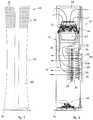
fig. 1 is a front elevation view of a fan according to one embodiment of the present invention;fig. 2 is a view in section of the fan infig. 1 taken according to the section plan II-II visible infig. 3 ;fig. 3 is a cross section of the fan infig. 2 ;fig. 4 is a cross section of a variant of the fan infig. 2 ;- fig. 5 is a cross section of a variant of the fan in
fig. 2 ; - fig. 6 is a cross section of a variant of the fan in
fig. 2 ; - To facilitate comprehension, the same reference numbers have been used, where possible, to identify identical common elements in the drawings. It is understood that elements and characteristics of one embodiment can conveniently be incorporated into other embodiments without further clarifications.
- Embodiments described here with reference to
figs. 1-4 concern afan 10 usable in particular in closed spaces for ventilating air at room temperature, for cooling, heating, thermo-ventilating, dehumidifying or purifying air. - The
fan 10 comprises amain body 12 with a vertical development with respect to asupport base 18 on which it is positioned during use. - The
main body 12 defines inside it acompartment 13 for housing functional components. - The
fan 10 has alongitudinal aperture 16, and comprises aunit 14 to take in and distribute a stream of air W. - According to possible solutions, the air suction and
distribution unit 14 is located, at least for a substantial part, above thelongitudinal aperture 16. - The
longitudinal aperture 16 is disposed on the opposite side with respect to the space to be conditioned. In particular, thelongitudinal aperture 16 is located in the rear part of thefan 10, and the stream of air W exiting from thelongitudinal aperture 16 is deflected so as to reach the front zone located at the front of thefan 10, as indicated by arrows F infigs. 3 and 4 . - In general, the expressions "rear part" and "front zone" are only intended to define a functional relationship between these two parts, which have to be substantially opposite each other with respect to the
main body 12 and the user. - According to other embodiments, the air suction and
distribution unit 14 can comprise arotor 15 provided with suitably oriented blades to determine the suction of the air from the outside and its entrance into themain body 12, and adrive member 17 connected to therotor 15. - According to some embodiments, the suction and
distribution unit 14 can be oriented in such a way that the axis of rotation of therotor 15 is substantially parallel to the axis of development of thelongitudinal aperture 16. - According to possible embodiments, the air enters inside the
main body 12 through throughentrance holes 27. - According to some embodiments, the through
entrance holes 27 can be made at least partly above thelongitudinal aperture 16, in the top part and/or on the upper lateral wall of themain body 12. - The fact that the through
entrance holes 27 and the suction anddistribution unit 14 are disposed in the upper part of themain body 12 advantageously allows to take in and recirculate cleaner air compared with that in correspondence with the floor, where dust or other dirt can deposit. - The
compartment 13 allows to channel inside thefan 10 the stream of air W from the entrance holes 27 toward thelongitudinal aperture 16. - The
fan 10 also comprises a channelingelement 20 positioned near thelongitudinal aperture 16 and cooperating with it to direct the stream of air W toward the outside. - The channeling
element 20 is configured so as to allow the stream of air W exiting from thelongitudinal aperture 16 to adhere to anexternal surface 22 of themain body 12. In other words, the channelingelement 20 is able to deflect the stream of air W exiting from thelongitudinal aperture 16. - The channeling
element 20 comprises anactive surface 20a which, during use, is struck by the stream of air W exiting from thelongitudinal aperture 16. Theactive surface 20a can have a convex shape. - The channeling
element 20 makes the stream of air W exiting from thelongitudinal aperture 16 in its travel toward the front zone of thefan 10 follow the profile of theexternal surface 22. - Furthermore, in cooperation with the
external surface 22, the channelingelement 20 is configured to determine a minimum passage section of the stream of air W exiting from thecompartment 13. - In one formulation of the invention, the
external surface 22 has a rounded geometry, substantially without any discontinuities, so that the stream of air, exiting from the rear part of thefan 10, is conveyed adherent toward the front part and then toward the space to be ventilated or conditioned. - According to one aspect of the present invention, the rounded geometry is suitable to convey the stream of air W adherent to the
external surface 22 without creating significant variations in the development of the stream, and without creating disturbances, turbulence, discontinuities or any other factor that could disturb the development of the stream. - According to one embodiment, shown by way of example in
fig. 1 , themain body 12 can have a tapered shape in at least part of its vertical development. - In particular, according to an advantageous formulation, the
main body 12 has on its height a narrowing in section substantially in correspondence with thelongitudinal aperture 16. - By way of example, the diameter inside which the cross section of the
main body 12 is inscribed can be comprised in a range from 100mm to 230mm and the height of themain body 12 can be comprised in a range between 750mm and 850mm. - The
main body 12 can be configured to have a continuous surface in the front part, while in correspondence with thelongitudinal aperture 16 it has a profile folded toward the inside, to define thelongitudinal aperture 16 itself. - In this way, the particular rounded geometry of the
main body 12 in correspondence with thelongitudinal aperture 16 allows to convey the stream of air W adherent to theexternal surface 22, so as to form a surface film that is then propagated toward the front of thefan 10. - According to one aspect of the invention, in correspondence with the zone affected by the
longitudinal aperture 16, themain body 12 has a geometric section shape with aprofile 40 defined by a polyline, which can be approximated by a plurality of convex arc segments S1, S2, S3, ....SN located one after the other. - In particular, the
polyline profile 40 is configured to generate a stream of air in the front part of thefan 10 such as to guarantee a high level of comfort for a user. - According to some embodiments, the
profile 40 of the characteristic section has a symmetrical shape with respect to a median plane M of thefan 10 which joins the front part and rear part where there is thelongitudinal aperture 16. - It should be noted that the
profile 40 can affect only one zone of themain body 12, in particular that zone where thelongitudinal aperture 16 is made. - In some embodiments, the
longitudinal aperture 16 and theprofile 40 can affect the whole longitudinal (vertical) development of themain body 12, or only one portion thereof. - According to some embodiments, in the direction of the stream of air from the
longitudinal aperture 16 to the front part of thefan 10, the successive convex arc segments have a progressively decreasing amplitude and a progressively increasing radius of curvature. - According to some embodiments, the convex arc segments S1, S2, S3, ....SN are tangent to each other.
- According to some embodiments, for example shown with reference to
fig. 3 , theprofile 40 can be approximated by at least three convex arc segments S1, S2, S3. - Even if in the following description we refer by way of example to three arc segments, it is clear that there can be any number N of convex arc segments, for example five, seven, ten, twenty, one hundred or more, provided that the convex arc segments have a progressively decreasing amplitude with respect to each other in the direction of the stream of air, and a progressively increasing radius of curvature.
- According to some embodiments, the first convex arc segment S1 can extend for an amplitude corresponding to a first angle α1, comprised for example between 110° and 150°, and can have a first radius of curvature R1 comprised between 5mm and 10mm. In particular, the first radius of curvature R1 can be comprised between 6mm and 8mm. For example the first radius of curvature R1 can be comprised between 6.8mm and 7.2mm.
- According to other embodiments, the first convex arc segment S1 can extend for an amplitude corresponding to a first angle α1, comprised between 120° and 140°, and can have a first radius of curvature R1 which can be comprised for example between 6.9mm and 7.1mm.
- According to other embodiments, the second convex arc segment S2 can extend for an amplitude corresponding to a second angle α2, comprised for example between 50° and 70°, and can have a second radius of curvature R2 comprised between 25mm and 45mm. In particular, the second radius of curvature R2 can be comprised between 30mm and 40mm.
- According to other embodiments, the second convex arc segment S2 can extend for an amplitude corresponding to a second angle α2, comprised between 55° and 65°, and can have a second radius of curvature R2 comprised between 32mm and 37 mm.
- According to some embodiments, the third convex arc segment S3 can extend for an amplitude corresponding to a third angle α3, comprised for example between 20° and 40°, and can have a third radius of curvature R3 comprised between 80mm and 130 mm. In particular, the third radius of curvature R3 can be comprised between 90mm and 120mm.
- According to other embodiments, the third convex arc segment S3 can extend for an amplitude corresponding to a third angle α3, comprised between 25° and 35°, and can have a third radius of curvature R3 comprised between 100mm and 110 mm, more particularly it can be comprised for example between 104mm and 106mm.
- According to some embodiments, the second convex arc segment S2 is tangent at one end with the first convex arc segment S1 and at the opposite end with the third convex arc segment S3, so that the
profile 40 has a development without discontinuities. - According to other embodiments, it can be provided that each convex arc segment S1, S2, S3 itself consists of a plurality of arc sub-segments, which in their entirety approximate the respective arc segments S1, S2, S3. Each arc sub-segment has, with respect to the previous segment (in the direction of the stream of air W) a progressively decreasing amplitude and a progressively increasing radius of curvature.
- For example, according to a possible embodiment, not shown, it can be provided that instead of the first convex arc segment S1, two arc sub-segments are disposed one after the other, and extend for respective amplitudes, for example with angles of 67° and 63°, and in which the respective radii of curvature can vary for example from 6.8mm to 7mm and from 7mm to 7.2mm.
- According to other embodiments, the curvature of the first convex arc segment S1 cooperates with the channeling
element 20 to define anexit passage 21 for the stream of air. - According to other embodiments, the channeling
element 20 can have an arched shape, with a radius of curvature suitable to cooperate with the first arc segments to define anexit passage 21 on each side of the median plane M. - According to some embodiments, the channeling
element 20 can have a curvilinear profile, which can be positioned above the portion of theexternal surface 22 in correspondence with thelongitudinal aperture 16. - In one embodiment, the channeling
element 20 has a longitudinal development at least equal to the extension of thelongitudinal aperture 16. - In another embodiment, shown in
fig. 2 , the channelingelement 20 has a vertical development equal to the development of themain body 12. - In another embodiment, shown by way of example in
fig. 4 , the channelingelement 20 can provide aseparator element 24 configured to determine a separation substantially into two halves of the stream of air W exiting from thelongitudinal aperture 16. - According to some embodiments, the
separator element 24 can have in section a triangle or arrow shape, with an apex 24a facing toward thelongitudinal aperture 16 and the base facing toward the channelingelement 20. - According to other embodiments, the
separator element 24 can have concave sides, arched toward the inside. - In some embodiments, the apex 24a can be rounded or beveled.
- The presence of the
separator element 24 allows to obtain a progressive reduction in the transit section of the air, which is maximum in correspondence with thelongitudinal aperture 16, that is, on the apex 24a of theseparator element 24, and is minimum in correspondence with the end of theexit passage 21, that is, in correspondence with the outermost end of the channelingelement 20. - The reduction in section between the apex 24a of the
separator element 24 and thepassage 21 can therefore determine an increase in the speed of the stream of air W toward the outside and toward the front part of thefan 10. - In this way two streams of air W are created, with opposite directions, each of which, exiting from a
respective passage 21, adheres with a respective portion of theexternal surface 22 of themain body 12, with the streams substantially combining again on the front of thefan 10. - According to some embodiments, the
passage 21 is conformed as a narrowing in section for the passage of the stream of air W. - According to some embodiments, each
passage 21 has a width comprised between about 0.1mm and 50mm. - According to some embodiments, the
passage 21 has a width comprised between about 1mm and about 20mm. - According to other embodiments, the
passage 21 has a width comprised between about 3mm and about 10mm. - The width of the
passage 21 thus designed allows to supply a stream of air toward the user with a speed suitable to confer on the user a sensation of optimum comfort at the desired distance. - In particular, the speed of the stream of air at exit is such as to optimize both the effectiveness of the functioning of the
fan 10 and the comfort of the user. - In particular, thanks to the fact that in correspondence with the longitudinal aperture 16 a wing-shaped
profile 40 is formed, the stream of air W is kept adherent to theexternal surface 22 for a greater segment than it would be if the section were circular and constant for the whole height of themain body 12. Consequently, the stream of air W that strikes the user will be more intense and less turbulent. - For example, according to some embodiments, the stream of air W obtained with the
fan 10 according to the invention, at a distance comprised between about 50cm and about 300cm from thefan 10, has a front that develops substantially uniform in a longitudinal direction, such as to optimize a feeling of heat wellbeing in the user. More particularly, the distance can be comprised between 150cm and 300cm. - According to other embodiments, the
external surface 22 of themain body 12, at least in correspondence with the sections defined by thepolyline profile 40, has a surface finish suitable to eliminate, or at least reduce, possible wrinkles and roughness, so as to prevent turbulence in the stream of air, thus guaranteeing a high level of comfort for the user. - According to some embodiments, the
external surface 22 can have a surface roughness comprised between 0.001µ and 100µ measured in terms of Ra, Rz and Rq. - According to other embodiments, the
external surface 22 can have a surface roughness comprised between 0.01µ and 50µ. - The combination of the geometric shape of the
profile 40, the width of thepassage 21 and the surface roughness as described above determines optimum comfort for the user, since the speed, temperature and turbulence of the stream of air generated are such as to guarantee a homogeneous stream on the horizontal plane, which can surround the user without creating hotter or colder points in localized parts of the body. - For example, considering three characteristic heights for a person seated and standing, and considering a room temperature T of not more than 21°C for heating and not less than 24°C for cooling, the geometric parameters given above allow to obtain a stream of air with the following characteristics of speed, temperature and turbulence.
- For example, in the case of heating, the speed at a height corresponding to the heels of a user is a non-zero value and can be, for example, less than about 0.6m/s, while the maximum speed of the stream of air at a distance of about 50cm from the
fan 10 can be less than 2m/s, so as to prevent localized cooling effects. - In the case of cooling, the speed at a height corresponding to the heels of a user can be more than 0.1m/s, and in any case for every longitudinal section not less than 0.05m/s.
- According to some embodiments, the temperature of the stream of air in heating mode can be higher than room temperature for all the sections characterized by the shape of the
profile 40, while in cooling mode the temperature can be the same as the room temperature. - Finally, with regard to turbulence, this can be eliminated or at least significantly reduced compared with that in known apparatuses. For example, with the
profile 40 according to the invention the turbulence of the stream of air W will always be less than 50% and, in particular, in the sections where the stream of air has maximum speed, the turbulence will be less than 20%. - In this way, for each section characterized by a
profile 40, a homogeneous front of the stream of air is created, with a longitudinal development, characterized by small vertical gradients, which is able to generate a feeling of heat wellbeing in the user. - According to some embodiments, for example, the maximum speed gradients in the case of heating and cooling can be, respectively, less than 1m/s, or comprised between 1m/s and 3m/s.
- According to other embodiments, the maximum temperature gradients can be, in the case of heating, less than 3°C on the horizontal axis, and less than 3°C on the vertical axis.
- According to other embodiments, the maximum gradients of turbulence in the case of heating and cooling can be kept respectively less than 30% and less than 40%.
- According to some embodiments, the
fan 10 according to the invention allows to condition the zone where the user is in the best possible way. In particular, theprofile 40 allows to supply a homogeneous stream of air that tends to improve the user's perception of the heat, without needing to condition the whole room, thus allowing to obtain great energy saving. - Indeed, the energy consumption needed to create a zone of heat wellbeing surrounding a user is less than the energy consumption that would be needed to guarantee the same heat wellbeing by conditioning the whole room.
- According to other embodiments, shown by way of example in
fig. 2 , thefan 10 can also comprise afiltering element 26, installed upstream of the air suction anddistribution unit 14 and in correspondence with the entrance holes 27, so that the air sucked in can be suitably cleaned and purified of dust or particular allergens present in it. - According to another embodiment, shown by way of example in
fig. 2 , thefan 10 can comprise aconditioning device 28 installed inside themain body 12 and in substantial correspondence with thelongitudinal aperture 16. - The
conditioning device 28 can be any device whatsoever, able to modify the condition of the stream of air W to supply a determinate effect inside the space where it is emitted by thefan 10. - For example, the
conditioning device 28 can supply heating, cooling or dehumidification of the stream of air W, or also a combination of these in the case of afan 10 designed to perform diverse functions according to requirements. - According to embodiments described here, the
fan 10 comprises adeflector device 34 provided with a plurality ofdeflector elements 35 to convey the stream of air through thelongitudinal aperture 16 and toward the channelingelement 20. - According to another embodiment, shown by way of example in
figs. 2 and3 , thefan 10 can comprise anadjustment device 36 which cooperates with thedeflector device 34 to determine the desired orientation of thedeflector elements 35, in order to modulate the direction of the stream of air W. - In one embodiment, the
adjustment device 36 can determine the rotation of thedeflector elements 35 from a position substantially parallel to thesupport base 18 to a position substantially perpendicular to thesupport base 18. - According to another embodiment, shown by way of example in
fig. 2 , thefan 10 also comprises adevice 30 to rotate themain body 12, so that it is possible to direct the jet of air as a function of the position of the user. - It is clear that modifications and/or additions of parts may be made to the
fan 10 as described heretofore, without departing from the field and scope of the present invention. - It is also clear that, although the present invention has been described with reference to some specific examples, a person of skill in the art shall certainly be able to achieve many other equivalent forms of fan, having the characteristics as set forth in the claims and hence all coming within the field of protection defined thereby.
Claims (13)
- Fan comprising a main body (12) with a vertical development with respect to a support base (18) on which it is located in a condition of use, said main body (12) defining an internal housing compartment (13), wherein it has a rear longitudinal aperture (16), for the emission of a stream of air (W) toward the outside, and also comprises an air suction and distribution unit (14) disposed above said longitudinal aperture (16), entrance holes (27) made above said longitudinal aperture (16), in the top part and/or on the upper lateral wall of said main body (12), and a channeling element (20) positioned in proximity to said longitudinal aperture (16) and cooperating with it to divert said stream of air (W) so that said stream of air (W) is conveyed toward a front part of the fan (10), at least partly following a profile (40) of an external surface (22) of the main body (12), wherein said profile (40) comprises a polyline approximated by a plurality of convex arc segments (S1, S2, S3, ....SN) located one after the other, said polyline profile (40) being configured to generate a stream of air (W) toward the front part of the fan such as to guarantee a high level of comfort for a user, and wherein said external surface (22) of said main body (12) has a rounded geometry substantially without discontinuities so that the stream of air (W), exiting from the rear part of the fan, is conveyed adherent toward the front part and then toward the external environment to be ventilated or conditioned.
- Fan as in claim 1,characterized in that said convex arc segments (S1, S2, S3, ....SN) that form said polyline have a progressively increasing radius of curvature, and a progressively decreasing amplitude in the direction of the stream of air (W), that is, from the longitudinal aperture (16) toward the front part of the fan.
- Fan as in claim 1 or 2,characterized in that said profile (40) has a symmetrical shape with respect to a median plane (M) of the fan, which joins the front part and a rear part where said longitudinal aperture (16) is made.
- Fan as in any claim hereinbefore,characterized in that said convex arc segments (S1, S2, S3,... SN) are in pairs tangent to each other.
- Fan as in any claim hereinbefore,characterized in that said profile (40) is approximated by at least three convex arc segments (S1, S2, S3), wherein a first convex arc segment (S1) extends for an amplitude corresponding to a first angle (α1) comprised between 110° and 150°, with a first radius of curvature (R1) comprised between 5mm and 10mm, in particular between 6mm and 8mm, for example comprised between 6.8mm and 7.2mm, a second convex arc segment (S2) extends for an amplitude corresponding to a second angle (α2) comprised between 50° and 70°, with a second radius of curvature (R2) comprised between 25mm and 45mm, in particular between 30mm and 40mm, for example comprised between 32mm and 37mm, and wherein a third convex arc segment (S3) extends for an amplitude corresponding to a third angle (α3) comprised between 25° and 35°, with a third radius of curvature (R3) comprised between 80mm and 130 mm, in particular, between 90mm and 120mm, for example comprised between 100mm and 110mm.
- Fan as in any claim hereinbefore,characterized in that said channeling element (20) has a curvilinear profile which can overlap the portion of said external surface (22) in correspondence with said longitudinal aperture (16).
- Fan as in any claim hereinbefore,characterized in that said channeling element (20), in cooperation with said external surface (22), is configured to determine a minimum section for the passage of said stream of air (W) exiting from said compartment (13).
- Fan as in claim 7,characterized in that said passage (21) has a width comprised between about 0.1mm and 50mm.
- Fan as in any claim hereinbefore,characterized in that said external surface (22), at least in correspondence with the sections defined by said polyline profile (40), can have a surface roughness comprised between 0.001µ and 100 µ, measured in terms of Ra, Rz and Rq.
- Fan as in any claim hereinbefore,characterized in that, for each section having said profile (40), said stream of air (W) has a homogeneous front with a longitudinal development, wherein said stream of air (W), at a distance comprised between about 50cm and about 300cm from the fan, has defined and uniform values of temperature, speed and turbulence, with small gradients and deviations from a mean value, such as to generate a feeling of heat wellbeing in the user.
- Fan as in any claim hereinbefore,characterized in that said channeling element (20) comprises a separator element (24) configured to determine a separation substantially into two halves of said stream of air (W) exiting from said longitudinal aperture (16).
- Fan as in claims 7 and 11,characterized in that said separator element (24) has in section a triangle or arrow shape, with an apex (24a) facing toward said longitudinal aperture (16) and the base facing toward said channeling element (20), said triangle or arrow shaped section determining a progressive reduction in the transit section of the air from said apex (24a) of said separator element (24) toward said exit passage (21).
- Fan as in any claim hereinbefore,characterized in that it comprises a filtering element (26) located upstream of said suction and distribution unit (14) and in correspondence with entrance holes (27) of the stream of air (W).
Applications Claiming Priority (3)
| Application Number | Priority Date | Filing Date | Title |
|---|---|---|---|
| ITUA2016A003574AITUA20163574A1 (en) | 2016-05-18 | 2016-05-18 | FAN |
| IT201700051934 | 2017-05-12 | ||
| PCT/EP2017/061965WO2017198765A1 (en) | 2016-05-18 | 2017-05-18 | Fan |
Publications (2)
| Publication Number | Publication Date |
|---|---|
| EP3458719A1 EP3458719A1 (en) | 2019-03-27 |
| EP3458719B1true EP3458719B1 (en) | 2020-05-13 |
Family
ID=58737568
Family Applications (1)
| Application Number | Title | Priority Date | Filing Date |
|---|---|---|---|
| EP17724350.8AActiveEP3458719B1 (en) | 2016-05-18 | 2017-05-18 | Fan |
Country Status (11)
| Country | Link |
|---|---|
| US (2) | US11326613B2 (en) |
| EP (1) | EP3458719B1 (en) |
| JP (2) | JP6964095B2 (en) |
| KR (2) | KR20190015325A (en) |
| CN (2) | CN109416047B (en) |
| AU (2) | AU2017266310B2 (en) |
| BR (2) | BR112018073723A2 (en) |
| CA (2) | CA3024343A1 (en) |
| MX (2) | MX2018014266A (en) |
| RU (2) | RU2734367C2 (en) |
| WO (2) | WO2017198763A1 (en) |
Families Citing this family (13)
| Publication number | Priority date | Publication date | Assignee | Title |
|---|---|---|---|---|
| WO2021075896A1 (en) | 2019-10-18 | 2021-04-22 | 엘지전자 주식회사 | Blower |
| KR102622928B1 (en)* | 2019-10-18 | 2024-01-08 | 엘지전자 주식회사 | Air cleaning apparatus |
| KR20210112122A (en)* | 2020-03-04 | 2021-09-14 | 엘지전자 주식회사 | Blower |
| US11982293B2 (en) | 2020-03-04 | 2024-05-14 | Lg Electronics Inc. | Blower |
| US11754090B2 (en) | 2020-03-04 | 2023-09-12 | Lg Electronics Inc. | Blower |
| US11473593B2 (en) | 2020-03-04 | 2022-10-18 | Lg Electronics Inc. | Blower comprising a fan installed in an inner space of a lower body having a first and second upper body positioned above and a space formed between the bodies wherein the bodies have a first and second openings formed through respective boundary surfaces which are opened and closed by a door assembly |
| EP4145001B1 (en)* | 2020-03-11 | 2024-08-14 | LG Electronics, Inc. | Blower |
| US11920611B2 (en) | 2020-03-11 | 2024-03-05 | Lg Electronics Inc. | Blower |
| TWI857394B (en)* | 2020-05-14 | 2024-10-01 | 南韓商Lg電子股份有限公司 | Blower |
| KR102399917B1 (en)* | 2020-05-18 | 2022-05-19 | 엘지전자 주식회사 | Blower |
| WO2021235619A1 (en)* | 2020-05-18 | 2021-11-25 | 엘지전자 주식회사 | Blower |
| JP7620829B2 (en)* | 2021-09-02 | 2025-01-24 | パナソニックIpマネジメント株式会社 | Blower |
| KR102572842B1 (en)* | 2021-09-03 | 2023-08-29 | 엘지전자 주식회사 | Blower |
Family Cites Families (40)
| Publication number | Priority date | Publication date | Assignee | Title |
|---|---|---|---|---|
| US2255759A (en)* | 1940-04-24 | 1941-09-16 | Howard H Carpenter | Electric heating appliance |
| US2471784A (en)* | 1945-11-19 | 1949-05-31 | Seifner | Heat exchange unit |
| US2583374A (en)* | 1950-10-18 | 1952-01-22 | Hydraulic Supply Mfg Company | Exhaust fan |
| BE560119A (en)* | 1956-09-13 | |||
| US3429527A (en)* | 1966-01-19 | 1969-02-25 | Dehavilland Aircraft Canada | Vertical take-off winged aircraft structure and method |
| US3500738A (en)* | 1967-12-12 | 1970-03-17 | Norman B Wenig | Multiple use air moving apparatus |
| US3885891A (en)* | 1972-11-30 | 1975-05-27 | Rockwell International Corp | Compound ejector |
| US3830450A (en)* | 1972-12-15 | 1974-08-20 | Us Navy | Dual purpose circulation control airfoil |
| US4332529A (en)* | 1975-08-11 | 1982-06-01 | Morton Alperin | Jet diffuser ejector |
| JPS56167897A (en)* | 1980-05-28 | 1981-12-23 | Toshiba Corp | Fan |
| US4448354A (en)* | 1982-07-23 | 1984-05-15 | The United States Of America As Represented By The Secretary Of The Air Force | Axisymmetric thrust augmenting ejector with discrete primary air slot nozzles |
| US4815942A (en)* | 1982-10-25 | 1989-03-28 | Elayne P. Alperin | Axially-symmetric, jet-diffuser ejector |
| US4466819A (en)* | 1983-08-11 | 1984-08-21 | Owens-Corning Fiberglas Corporation | Method and apparatus for producing a continuous glass filament mat |
| FI69332C (en)* | 1984-03-02 | 1986-01-10 | Valmet Oy | ANORDNING I TORKNINGSPARTIET AV EN PAPPERSMASKIN |
| US4856968A (en)* | 1988-02-02 | 1989-08-15 | Armbruster Joseph M | Air circulation device |
| SU1643799A1 (en)* | 1989-02-13 | 1991-04-23 | Snegov Anatolij A | Domestic fan |
| US5762034A (en)* | 1996-01-16 | 1998-06-09 | Board Of Trustees Operating Michigan State University | Cooling fan shroud |
| US6073881A (en)* | 1998-08-18 | 2000-06-13 | Chen; Chung-Ching | Aerodynamic lift apparatus |
| US6321034B2 (en)* | 1999-12-06 | 2001-11-20 | The Holmes Group, Inc. | Pivotable heater |
| US6830433B2 (en)* | 2002-08-05 | 2004-12-14 | Kaz, Inc. | Tower fan |
| US7699580B2 (en)* | 2002-12-18 | 2010-04-20 | Lasko Holdings, Inc. | Portable air moving device |
| US6760543B1 (en)* | 2002-12-18 | 2004-07-06 | Lasko Holdings, Inc. | Heated air circulator with uniform exhaust airflow |
| GB0903682D0 (en)* | 2009-03-04 | 2009-04-15 | Dyson Technology Ltd | A fan |
| GB2468329A (en)* | 2009-03-04 | 2010-09-08 | Dyson Technology Ltd | Fan assembly |
| NZ593318A (en)* | 2009-03-04 | 2012-11-30 | Dyson Technology Ltd | An annular fan assembly with a silencing member |
| GB2468322B (en)* | 2009-03-04 | 2011-03-16 | Dyson Technology Ltd | Tilting fan stand |
| GB2482548A (en)* | 2010-08-06 | 2012-02-08 | Dyson Technology Ltd | A fan assembly with a heater |
| US20120051884A1 (en)* | 2010-08-28 | 2012-03-01 | Zhongshan Longde Electric Industries Co., Ltd. | Air blowing device |
| KR101229109B1 (en)* | 2011-01-21 | 2013-02-05 | (주)엠파워텍 | Hair dryer |
| TWI433994B (en)* | 2011-01-25 | 2014-04-11 | Delta Electronics Inc | Fan assembly |
| KR20130013892A (en)* | 2011-07-29 | 2013-02-06 | 남순호 | Wingless electric fan |
| JP6012965B2 (en) | 2012-01-11 | 2016-10-25 | シャープ株式会社 | Blower device and method |
| GB2500017B (en)* | 2012-03-06 | 2015-07-29 | Dyson Technology Ltd | A Humidifying Apparatus |
| JP5994643B2 (en)* | 2013-01-09 | 2016-09-21 | 株式会社デンソー | Blower |
| JP2015063979A (en)* | 2013-09-26 | 2015-04-09 | パナソニック株式会社 | Blower |
| CN104863871B (en) | 2014-05-06 | 2018-01-30 | 广东美的环境电器制造有限公司 | Fan |
| CN204328743U (en)* | 2014-12-04 | 2015-05-13 | 贾传瑞 | Without leaf Lamp with ceiling fan |
| CN104832443B (en)* | 2015-05-25 | 2017-05-24 | 广东美的环境电器制造有限公司 | fan |
| CN105351230B (en)* | 2015-12-10 | 2017-11-28 | 南华大学 | Coanda fin ventilation fan |
| FR3065752B1 (en)* | 2017-04-28 | 2021-01-01 | Valeo Systemes Thermiques | COANDA-EFFECT TUBE VENTILATION DEVICE WITH DOUBLE EJECTORS FOR MOTOR VEHICLE HEAT EXCHANGE MODULE |
- 2017
- 2017-05-18EPEP17724350.8Apatent/EP3458719B1/enactiveActive
- 2017-05-18USUS16/303,087patent/US11326613B2/enactiveActive
- 2017-05-18RURU2018144848Apatent/RU2734367C2/enactive
- 2017-05-18BRBR112018073723-2Apatent/BR112018073723A2/ennot_activeIP Right Cessation
- 2017-05-18USUS16/303,066patent/US11326612B2/enactiveActive
- 2017-05-18KRKR1020187036766Apatent/KR20190015325A/ennot_activeAbandoned
- 2017-05-18CNCN201780042341.7Apatent/CN109416047B/enactiveActive
- 2017-05-18CACA3024343Apatent/CA3024343A1/ennot_activeAbandoned
- 2017-05-18JPJP2018560487Apatent/JP6964095B2/enactiveActive
- 2017-05-18AUAU2017266310Apatent/AU2017266310B2/enactiveActive
- 2017-05-18WOPCT/EP2017/061960patent/WO2017198763A1/ennot_activeCeased
- 2017-05-18KRKR1020187036765Apatent/KR20190015324A/ennot_activeAbandoned
- 2017-05-18WOPCT/EP2017/061965patent/WO2017198765A1/ennot_activeCeased
- 2017-05-18MXMX2018014266Apatent/MX2018014266A/enunknown
- 2017-05-18JPJP2018560473Apatent/JP6964094B2/enactiveActive
- 2017-05-18AUAU2017266312Apatent/AU2017266312B2/enactiveActive
- 2017-05-18BRBR112018073722-4Apatent/BR112018073722A2/ennot_activeIP Right Cessation
- 2017-05-18CACA3024352Apatent/CA3024352A1/ennot_activeAbandoned
- 2017-05-18RURU2018144836Apatent/RU2733158C2/enactive
- 2017-05-18CNCN201780042337.0Apatent/CN109477491B/enactiveActive
- 2017-05-18MXMX2018014265Apatent/MX2018014265A/enunknown
Non-Patent Citations (1)
| Title |
|---|
| None* |
Also Published As
| Publication number | Publication date |
|---|---|
| RU2018144836A3 (en) | 2020-08-03 |
| WO2017198763A1 (en) | 2017-11-23 |
| CN109416047B (en) | 2023-08-01 |
| AU2017266312A1 (en) | 2018-12-06 |
| US20190277297A1 (en) | 2019-09-12 |
| BR112018073722A2 (en) | 2019-02-26 |
| MX2018014265A (en) | 2019-11-28 |
| US20190301475A1 (en) | 2019-10-03 |
| RU2018144848A3 (en) | 2020-08-03 |
| CN109477491A (en) | 2019-03-15 |
| JP6964094B2 (en) | 2021-11-10 |
| US11326612B2 (en) | 2022-05-10 |
| WO2017198765A1 (en) | 2017-11-23 |
| AU2017266310B2 (en) | 2022-08-04 |
| AU2017266312B2 (en) | 2022-06-30 |
| CN109477491B (en) | 2021-02-19 |
| RU2733158C2 (en) | 2020-09-29 |
| EP3458719A1 (en) | 2019-03-27 |
| MX2018014266A (en) | 2019-11-28 |
| JP2019522138A (en) | 2019-08-08 |
| BR112018073723A2 (en) | 2019-02-26 |
| RU2018144836A (en) | 2020-06-18 |
| US11326613B2 (en) | 2022-05-10 |
| CA3024343A1 (en) | 2017-11-23 |
| AU2017266310A1 (en) | 2018-12-06 |
| JP2019519710A (en) | 2019-07-11 |
| RU2734367C2 (en) | 2020-10-15 |
| CA3024352A1 (en) | 2017-11-23 |
| KR20190015325A (en) | 2019-02-13 |
| KR20190015324A (en) | 2019-02-13 |
| JP6964095B2 (en) | 2021-11-10 |
| CN109416047A (en) | 2019-03-01 |
| RU2018144848A (en) | 2020-06-18 |
Similar Documents
| Publication | Publication Date | Title |
|---|---|---|
| EP3458719B1 (en) | Fan | |
| CN104697053B (en) | Air conditioner room unit and deep bead | |
| JP2014020652A (en) | Wind direction control device, and blower | |
| JP2011007367A (en) | Smoke guide plate and smoking area | |
| EP3458721B1 (en) | Fan | |
| JP6845622B2 (en) | Air conditioning ducts for vehicles and railcars | |
| JP5589405B2 (en) | Blower | |
| JP4311631B2 (en) | Ion diffusion device | |
| CN207394984U (en) | Wind shield, air conditioner room unit and air conditioner | |
| JP5763413B2 (en) | partition | |
| CN117677800A (en) | Air outlet of air conditioning unit | |
| CN106322710B (en) | Air conditioner air deflector and air-conditioning | |
| KR102683500B1 (en) | Quarantine table | |
| JP7386387B2 (en) | Air blower | |
| JP2012002369A (en) | Air cleaner | |
| JP2004085128A (en) | Air conditioner | |
| JPH0960959A (en) | Clean room air blowout duct | |
| KR20110000787U (en) | Cool air circulation device for air-conditioner the ceiling | |
| CN117346223A (en) | Air conditioner indoor unit and air conditioner | |
| JP2015039467A (en) | Bathroom heating dryer with mist sauna function | |
| JP2009097851A (en) | Air conditioner | |
| JPH10170037A (en) | Smoke air cleaner |
Legal Events
| Date | Code | Title | Description |
|---|---|---|---|
| STAA | Information on the status of an ep patent application or granted ep patent | Free format text:STATUS: UNKNOWN | |
| STAA | Information on the status of an ep patent application or granted ep patent | Free format text:STATUS: THE INTERNATIONAL PUBLICATION HAS BEEN MADE | |
| PUAI | Public reference made under article 153(3) epc to a published international application that has entered the european phase | Free format text:ORIGINAL CODE: 0009012 | |
| STAA | Information on the status of an ep patent application or granted ep patent | Free format text:STATUS: REQUEST FOR EXAMINATION WAS MADE | |
| 17P | Request for examination filed | Effective date:20181130 | |
| AK | Designated contracting states | Kind code of ref document:A1 Designated state(s):AL AT BE BG CH CY CZ DE DK EE ES FI FR GB GR HR HU IE IS IT LI LT LU LV MC MK MT NL NO PL PT RO RS SE SI SK SM TR | |
| AX | Request for extension of the european patent | Extension state:BA ME | |
| DAV | Request for validation of the european patent (deleted) | ||
| DAX | Request for extension of the european patent (deleted) | ||
| GRAP | Despatch of communication of intention to grant a patent | Free format text:ORIGINAL CODE: EPIDOSNIGR1 | |
| STAA | Information on the status of an ep patent application or granted ep patent | Free format text:STATUS: GRANT OF PATENT IS INTENDED | |
| INTG | Intention to grant announced | Effective date:20200203 | |
| GRAS | Grant fee paid | Free format text:ORIGINAL CODE: EPIDOSNIGR3 | |
| GRAA | (expected) grant | Free format text:ORIGINAL CODE: 0009210 | |
| STAA | Information on the status of an ep patent application or granted ep patent | Free format text:STATUS: THE PATENT HAS BEEN GRANTED | |
| AK | Designated contracting states | Kind code of ref document:B1 Designated state(s):AL AT BE BG CH CY CZ DE DK EE ES FI FR GB GR HR HU IE IS IT LI LT LU LV MC MK MT NL NO PL PT RO RS SE SI SK SM TR | |
| REG | Reference to a national code | Ref country code:GB Ref legal event code:FG4D | |
| REG | Reference to a national code | Ref country code:CH Ref legal event code:EP | |
| REG | Reference to a national code | Ref country code:DE Ref legal event code:R096 Ref document number:602017016521 Country of ref document:DE | |
| REG | Reference to a national code | Ref country code:AT Ref legal event code:REF Ref document number:1270661 Country of ref document:AT Kind code of ref document:T Effective date:20200615 | |
| REG | Reference to a national code | Ref country code:LT Ref legal event code:MG4D | |
| REG | Reference to a national code | Ref country code:NL Ref legal event code:MP Effective date:20200513 | |
| PG25 | Lapsed in a contracting state [announced via postgrant information from national office to epo] | Ref country code:IS Free format text:LAPSE BECAUSE OF FAILURE TO SUBMIT A TRANSLATION OF THE DESCRIPTION OR TO PAY THE FEE WITHIN THE PRESCRIBED TIME-LIMIT Effective date:20200913 Ref country code:NO Free format text:LAPSE BECAUSE OF FAILURE TO SUBMIT A TRANSLATION OF THE DESCRIPTION OR TO PAY THE FEE WITHIN THE PRESCRIBED TIME-LIMIT Effective date:20200813 Ref country code:FI Free format text:LAPSE BECAUSE OF FAILURE TO SUBMIT A TRANSLATION OF THE DESCRIPTION OR TO PAY THE FEE WITHIN THE PRESCRIBED TIME-LIMIT Effective date:20200513 Ref country code:PT Free format text:LAPSE BECAUSE OF FAILURE TO SUBMIT A TRANSLATION OF THE DESCRIPTION OR TO PAY THE FEE WITHIN THE PRESCRIBED TIME-LIMIT Effective date:20200914 Ref country code:SE Free format text:LAPSE BECAUSE OF FAILURE TO SUBMIT A TRANSLATION OF THE DESCRIPTION OR TO PAY THE FEE WITHIN THE PRESCRIBED TIME-LIMIT Effective date:20200513 Ref country code:GR Free format text:LAPSE BECAUSE OF FAILURE TO SUBMIT A TRANSLATION OF THE DESCRIPTION OR TO PAY THE FEE WITHIN THE PRESCRIBED TIME-LIMIT Effective date:20200814 Ref country code:LT Free format text:LAPSE BECAUSE OF FAILURE TO SUBMIT A TRANSLATION OF THE DESCRIPTION OR TO PAY THE FEE WITHIN THE PRESCRIBED TIME-LIMIT Effective date:20200513 | |
| PG25 | Lapsed in a contracting state [announced via postgrant information from national office to epo] | Ref country code:RS Free format text:LAPSE BECAUSE OF FAILURE TO SUBMIT A TRANSLATION OF THE DESCRIPTION OR TO PAY THE FEE WITHIN THE PRESCRIBED TIME-LIMIT Effective date:20200513 Ref country code:BG Free format text:LAPSE BECAUSE OF FAILURE TO SUBMIT A TRANSLATION OF THE DESCRIPTION OR TO PAY THE FEE WITHIN THE PRESCRIBED TIME-LIMIT Effective date:20200813 Ref country code:LV Free format text:LAPSE BECAUSE OF FAILURE TO SUBMIT A TRANSLATION OF THE DESCRIPTION OR TO PAY THE FEE WITHIN THE PRESCRIBED TIME-LIMIT Effective date:20200513 Ref country code:HR Free format text:LAPSE BECAUSE OF FAILURE TO SUBMIT A TRANSLATION OF THE DESCRIPTION OR TO PAY THE FEE WITHIN THE PRESCRIBED TIME-LIMIT Effective date:20200513 | |
| REG | Reference to a national code | Ref country code:AT Ref legal event code:MK05 Ref document number:1270661 Country of ref document:AT Kind code of ref document:T Effective date:20200513 | |
| PG25 | Lapsed in a contracting state [announced via postgrant information from national office to epo] | Ref country code:AL Free format text:LAPSE BECAUSE OF FAILURE TO SUBMIT A TRANSLATION OF THE DESCRIPTION OR TO PAY THE FEE WITHIN THE PRESCRIBED TIME-LIMIT Effective date:20200513 Ref country code:NL Free format text:LAPSE BECAUSE OF FAILURE TO SUBMIT A TRANSLATION OF THE DESCRIPTION OR TO PAY THE FEE WITHIN THE PRESCRIBED TIME-LIMIT Effective date:20200513 | |
| PG25 | Lapsed in a contracting state [announced via postgrant information from national office to epo] | Ref country code:DK Free format text:LAPSE BECAUSE OF FAILURE TO SUBMIT A TRANSLATION OF THE DESCRIPTION OR TO PAY THE FEE WITHIN THE PRESCRIBED TIME-LIMIT Effective date:20200513 Ref country code:AT Free format text:LAPSE BECAUSE OF FAILURE TO SUBMIT A TRANSLATION OF THE DESCRIPTION OR TO PAY THE FEE WITHIN THE PRESCRIBED TIME-LIMIT Effective date:20200513 Ref country code:EE Free format text:LAPSE BECAUSE OF FAILURE TO SUBMIT A TRANSLATION OF THE DESCRIPTION OR TO PAY THE FEE WITHIN THE PRESCRIBED TIME-LIMIT Effective date:20200513 Ref country code:SM Free format text:LAPSE BECAUSE OF FAILURE TO SUBMIT A TRANSLATION OF THE DESCRIPTION OR TO PAY THE FEE WITHIN THE PRESCRIBED TIME-LIMIT Effective date:20200513 Ref country code:CZ Free format text:LAPSE BECAUSE OF FAILURE TO SUBMIT A TRANSLATION OF THE DESCRIPTION OR TO PAY THE FEE WITHIN THE PRESCRIBED TIME-LIMIT Effective date:20200513 Ref country code:CH Free format text:LAPSE BECAUSE OF NON-PAYMENT OF DUE FEES Effective date:20200531 Ref country code:RO Free format text:LAPSE BECAUSE OF FAILURE TO SUBMIT A TRANSLATION OF THE DESCRIPTION OR TO PAY THE FEE WITHIN THE PRESCRIBED TIME-LIMIT Effective date:20200513 Ref country code:LI Free format text:LAPSE BECAUSE OF NON-PAYMENT OF DUE FEES Effective date:20200531 Ref country code:ES Free format text:LAPSE BECAUSE OF FAILURE TO SUBMIT A TRANSLATION OF THE DESCRIPTION OR TO PAY THE FEE WITHIN THE PRESCRIBED TIME-LIMIT Effective date:20200513 | |
| REG | Reference to a national code | Ref country code:DE Ref legal event code:R097 Ref document number:602017016521 Country of ref document:DE | |
| PG25 | Lapsed in a contracting state [announced via postgrant information from national office to epo] | Ref country code:PL Free format text:LAPSE BECAUSE OF FAILURE TO SUBMIT A TRANSLATION OF THE DESCRIPTION OR TO PAY THE FEE WITHIN THE PRESCRIBED TIME-LIMIT Effective date:20200513 Ref country code:MC Free format text:LAPSE BECAUSE OF FAILURE TO SUBMIT A TRANSLATION OF THE DESCRIPTION OR TO PAY THE FEE WITHIN THE PRESCRIBED TIME-LIMIT Effective date:20200513 Ref country code:SK Free format text:LAPSE BECAUSE OF FAILURE TO SUBMIT A TRANSLATION OF THE DESCRIPTION OR TO PAY THE FEE WITHIN THE PRESCRIBED TIME-LIMIT Effective date:20200513 | |
| PLBE | No opposition filed within time limit | Free format text:ORIGINAL CODE: 0009261 | |
| STAA | Information on the status of an ep patent application or granted ep patent | Free format text:STATUS: NO OPPOSITION FILED WITHIN TIME LIMIT | |
| PG25 | Lapsed in a contracting state [announced via postgrant information from national office to epo] | Ref country code:LU Free format text:LAPSE BECAUSE OF NON-PAYMENT OF DUE FEES Effective date:20200518 | |
| 26N | No opposition filed | Effective date:20210216 | |
| PG25 | Lapsed in a contracting state [announced via postgrant information from national office to epo] | Ref country code:IE Free format text:LAPSE BECAUSE OF NON-PAYMENT OF DUE FEES Effective date:20200518 | |
| PG25 | Lapsed in a contracting state [announced via postgrant information from national office to epo] | Ref country code:SI Free format text:LAPSE BECAUSE OF FAILURE TO SUBMIT A TRANSLATION OF THE DESCRIPTION OR TO PAY THE FEE WITHIN THE PRESCRIBED TIME-LIMIT Effective date:20200513 | |
| PG25 | Lapsed in a contracting state [announced via postgrant information from national office to epo] | Ref country code:TR Free format text:LAPSE BECAUSE OF FAILURE TO SUBMIT A TRANSLATION OF THE DESCRIPTION OR TO PAY THE FEE WITHIN THE PRESCRIBED TIME-LIMIT Effective date:20200513 Ref country code:MT Free format text:LAPSE BECAUSE OF FAILURE TO SUBMIT A TRANSLATION OF THE DESCRIPTION OR TO PAY THE FEE WITHIN THE PRESCRIBED TIME-LIMIT Effective date:20200513 Ref country code:CY Free format text:LAPSE BECAUSE OF FAILURE TO SUBMIT A TRANSLATION OF THE DESCRIPTION OR TO PAY THE FEE WITHIN THE PRESCRIBED TIME-LIMIT Effective date:20200513 | |
| PG25 | Lapsed in a contracting state [announced via postgrant information from national office to epo] | Ref country code:MK Free format text:LAPSE BECAUSE OF FAILURE TO SUBMIT A TRANSLATION OF THE DESCRIPTION OR TO PAY THE FEE WITHIN THE PRESCRIBED TIME-LIMIT Effective date:20200513 | |
| P01 | Opt-out of the competence of the unified patent court (upc) registered | Effective date:20230513 | |
| PGFP | Annual fee paid to national office [announced via postgrant information from national office to epo] | Ref country code:DE Payment date:20250528 Year of fee payment:9 | |
| PGFP | Annual fee paid to national office [announced via postgrant information from national office to epo] | Ref country code:GB Payment date:20250520 Year of fee payment:9 | |
| PGFP | Annual fee paid to national office [announced via postgrant information from national office to epo] | Ref country code:BE Payment date:20250526 Year of fee payment:9 Ref country code:IT Payment date:20250514 Year of fee payment:9 | |
| PGFP | Annual fee paid to national office [announced via postgrant information from national office to epo] | Ref country code:FR Payment date:20250527 Year of fee payment:9 |