EP3457989B1 - Prosthetic valves, valve leaflets and related methods - Google Patents
Prosthetic valves, valve leaflets and related methodsDownload PDFInfo
- Publication number
- EP3457989B1 EP3457989B1EP17725140.2AEP17725140AEP3457989B1EP 3457989 B1EP3457989 B1EP 3457989B1EP 17725140 AEP17725140 AEP 17725140AEP 3457989 B1EP3457989 B1EP 3457989B1
- Authority
- EP
- European Patent Office
- Prior art keywords
- valve
- oxide
- leaflets
- layer
- fibrous matrix
- Prior art date
- Legal status (The legal status is an assumption and is not a legal conclusion. Google has not performed a legal analysis and makes no representation as to the accuracy of the status listed.)
- Active
Links
Images


Classifications
- A—HUMAN NECESSITIES
- A61—MEDICAL OR VETERINARY SCIENCE; HYGIENE
- A61F—FILTERS IMPLANTABLE INTO BLOOD VESSELS; PROSTHESES; DEVICES PROVIDING PATENCY TO, OR PREVENTING COLLAPSING OF, TUBULAR STRUCTURES OF THE BODY, e.g. STENTS; ORTHOPAEDIC, NURSING OR CONTRACEPTIVE DEVICES; FOMENTATION; TREATMENT OR PROTECTION OF EYES OR EARS; BANDAGES, DRESSINGS OR ABSORBENT PADS; FIRST-AID KITS
- A61F2/00—Filters implantable into blood vessels; Prostheses, i.e. artificial substitutes or replacements for parts of the body; Appliances for connecting them with the body; Devices providing patency to, or preventing collapsing of, tubular structures of the body, e.g. stents
- A61F2/02—Prostheses implantable into the body
- A61F2/24—Heart valves ; Vascular valves, e.g. venous valves; Heart implants, e.g. passive devices for improving the function of the native valve or the heart muscle; Transmyocardial revascularisation [TMR] devices; Valves implantable in the body
- A61F2/2412—Heart valves ; Vascular valves, e.g. venous valves; Heart implants, e.g. passive devices for improving the function of the native valve or the heart muscle; Transmyocardial revascularisation [TMR] devices; Valves implantable in the body with soft flexible valve members, e.g. tissue valves shaped like natural valves
- A—HUMAN NECESSITIES
- A61—MEDICAL OR VETERINARY SCIENCE; HYGIENE
- A61L—METHODS OR APPARATUS FOR STERILISING MATERIALS OR OBJECTS IN GENERAL; DISINFECTION, STERILISATION OR DEODORISATION OF AIR; CHEMICAL ASPECTS OF BANDAGES, DRESSINGS, ABSORBENT PADS OR SURGICAL ARTICLES; MATERIALS FOR BANDAGES, DRESSINGS, ABSORBENT PADS OR SURGICAL ARTICLES
- A61L27/00—Materials for grafts or prostheses or for coating grafts or prostheses
- A61L27/14—Macromolecular materials
- A—HUMAN NECESSITIES
- A61—MEDICAL OR VETERINARY SCIENCE; HYGIENE
- A61L—METHODS OR APPARATUS FOR STERILISING MATERIALS OR OBJECTS IN GENERAL; DISINFECTION, STERILISATION OR DEODORISATION OF AIR; CHEMICAL ASPECTS OF BANDAGES, DRESSINGS, ABSORBENT PADS OR SURGICAL ARTICLES; MATERIALS FOR BANDAGES, DRESSINGS, ABSORBENT PADS OR SURGICAL ARTICLES
- A61L27/00—Materials for grafts or prostheses or for coating grafts or prostheses
- A61L27/28—Materials for coating prostheses
- A61L27/30—Inorganic materials
- A61L27/306—Other specific inorganic materials not covered by A61L27/303 - A61L27/32
- B—PERFORMING OPERATIONS; TRANSPORTING
- B32—LAYERED PRODUCTS
- B32B—LAYERED PRODUCTS, i.e. PRODUCTS BUILT-UP OF STRATA OF FLAT OR NON-FLAT, e.g. CELLULAR OR HONEYCOMB, FORM
- B32B27/00—Layered products comprising a layer of synthetic resin
- B32B27/02—Layered products comprising a layer of synthetic resin in the form of fibres or filaments
- C—CHEMISTRY; METALLURGY
- C08—ORGANIC MACROMOLECULAR COMPOUNDS; THEIR PREPARATION OR CHEMICAL WORKING-UP; COMPOSITIONS BASED THEREON
- C08K—Use of inorganic or non-macromolecular organic substances as compounding ingredients
- C08K3/00—Use of inorganic substances as compounding ingredients
- C08K3/18—Oxygen-containing compounds, e.g. metal carbonyls
- C08K3/20—Oxides; Hydroxides
- C08K3/22—Oxides; Hydroxides of metals
- D—TEXTILES; PAPER
- D04—BRAIDING; LACE-MAKING; KNITTING; TRIMMINGS; NON-WOVEN FABRICS
- D04H—MAKING TEXTILE FABRICS, e.g. FROM FIBRES OR FILAMENTARY MATERIAL; FABRICS MADE BY SUCH PROCESSES OR APPARATUS, e.g. FELTS, NON-WOVEN FABRICS; COTTON-WOOL; WADDING ; NON-WOVEN FABRICS FROM STAPLE FIBRES, FILAMENTS OR YARNS, BONDED WITH AT LEAST ONE WEB-LIKE MATERIAL DURING THEIR CONSOLIDATION
- D04H1/00—Non-woven fabrics formed wholly or mainly of staple fibres or like relatively short fibres
- D04H1/40—Non-woven fabrics formed wholly or mainly of staple fibres or like relatively short fibres from fleeces or layers composed of fibres without existing or potential cohesive properties
- D04H1/54—Non-woven fabrics formed wholly or mainly of staple fibres or like relatively short fibres from fleeces or layers composed of fibres without existing or potential cohesive properties by welding together the fibres, e.g. by partially melting or dissolving
- D04H1/541—Composite fibres, e.g. sheath-core, sea-island or side-by-side; Mixed fibres
- D04H1/5412—Composite fibres, e.g. sheath-core, sea-island or side-by-side; Mixed fibres sheath-core
- A—HUMAN NECESSITIES
- A61—MEDICAL OR VETERINARY SCIENCE; HYGIENE
- A61F—FILTERS IMPLANTABLE INTO BLOOD VESSELS; PROSTHESES; DEVICES PROVIDING PATENCY TO, OR PREVENTING COLLAPSING OF, TUBULAR STRUCTURES OF THE BODY, e.g. STENTS; ORTHOPAEDIC, NURSING OR CONTRACEPTIVE DEVICES; FOMENTATION; TREATMENT OR PROTECTION OF EYES OR EARS; BANDAGES, DRESSINGS OR ABSORBENT PADS; FIRST-AID KITS
- A61F2/00—Filters implantable into blood vessels; Prostheses, i.e. artificial substitutes or replacements for parts of the body; Appliances for connecting them with the body; Devices providing patency to, or preventing collapsing of, tubular structures of the body, e.g. stents
- A61F2/02—Prostheses implantable into the body
- A61F2/24—Heart valves ; Vascular valves, e.g. venous valves; Heart implants, e.g. passive devices for improving the function of the native valve or the heart muscle; Transmyocardial revascularisation [TMR] devices; Valves implantable in the body
- A61F2/2412—Heart valves ; Vascular valves, e.g. venous valves; Heart implants, e.g. passive devices for improving the function of the native valve or the heart muscle; Transmyocardial revascularisation [TMR] devices; Valves implantable in the body with soft flexible valve members, e.g. tissue valves shaped like natural valves
- A61F2/2415—Manufacturing methods
- A—HUMAN NECESSITIES
- A61—MEDICAL OR VETERINARY SCIENCE; HYGIENE
- A61F—FILTERS IMPLANTABLE INTO BLOOD VESSELS; PROSTHESES; DEVICES PROVIDING PATENCY TO, OR PREVENTING COLLAPSING OF, TUBULAR STRUCTURES OF THE BODY, e.g. STENTS; ORTHOPAEDIC, NURSING OR CONTRACEPTIVE DEVICES; FOMENTATION; TREATMENT OR PROTECTION OF EYES OR EARS; BANDAGES, DRESSINGS OR ABSORBENT PADS; FIRST-AID KITS
- A61F2/00—Filters implantable into blood vessels; Prostheses, i.e. artificial substitutes or replacements for parts of the body; Appliances for connecting them with the body; Devices providing patency to, or preventing collapsing of, tubular structures of the body, e.g. stents
- A61F2/02—Prostheses implantable into the body
- A61F2/24—Heart valves ; Vascular valves, e.g. venous valves; Heart implants, e.g. passive devices for improving the function of the native valve or the heart muscle; Transmyocardial revascularisation [TMR] devices; Valves implantable in the body
- A61F2/2412—Heart valves ; Vascular valves, e.g. venous valves; Heart implants, e.g. passive devices for improving the function of the native valve or the heart muscle; Transmyocardial revascularisation [TMR] devices; Valves implantable in the body with soft flexible valve members, e.g. tissue valves shaped like natural valves
- A61F2/2418—Scaffolds therefor, e.g. support stents
- A—HUMAN NECESSITIES
- A61—MEDICAL OR VETERINARY SCIENCE; HYGIENE
- A61F—FILTERS IMPLANTABLE INTO BLOOD VESSELS; PROSTHESES; DEVICES PROVIDING PATENCY TO, OR PREVENTING COLLAPSING OF, TUBULAR STRUCTURES OF THE BODY, e.g. STENTS; ORTHOPAEDIC, NURSING OR CONTRACEPTIVE DEVICES; FOMENTATION; TREATMENT OR PROTECTION OF EYES OR EARS; BANDAGES, DRESSINGS OR ABSORBENT PADS; FIRST-AID KITS
- A61F2210/00—Particular material properties of prostheses classified in groups A61F2/00 - A61F2/26 or A61F2/82 or A61F9/00 or A61F11/00 or subgroups thereof
- A61F2210/0076—Particular material properties of prostheses classified in groups A61F2/00 - A61F2/26 or A61F2/82 or A61F9/00 or A61F11/00 or subgroups thereof multilayered, e.g. laminated structures
- A—HUMAN NECESSITIES
- A61—MEDICAL OR VETERINARY SCIENCE; HYGIENE
- A61F—FILTERS IMPLANTABLE INTO BLOOD VESSELS; PROSTHESES; DEVICES PROVIDING PATENCY TO, OR PREVENTING COLLAPSING OF, TUBULAR STRUCTURES OF THE BODY, e.g. STENTS; ORTHOPAEDIC, NURSING OR CONTRACEPTIVE DEVICES; FOMENTATION; TREATMENT OR PROTECTION OF EYES OR EARS; BANDAGES, DRESSINGS OR ABSORBENT PADS; FIRST-AID KITS
- A61F2250/00—Special features of prostheses classified in groups A61F2/00 - A61F2/26 or A61F2/82 or A61F9/00 or A61F11/00 or subgroups thereof
- A61F2250/0014—Special features of prostheses classified in groups A61F2/00 - A61F2/26 or A61F2/82 or A61F9/00 or A61F11/00 or subgroups thereof having different values of a given property or geometrical feature, e.g. mechanical property or material property, at different locations within the same prosthesis
- A61F2250/0015—Special features of prostheses classified in groups A61F2/00 - A61F2/26 or A61F2/82 or A61F9/00 or A61F11/00 or subgroups thereof having different values of a given property or geometrical feature, e.g. mechanical property or material property, at different locations within the same prosthesis differing in density or specific weight
- A61F2250/0017—Special features of prostheses classified in groups A61F2/00 - A61F2/26 or A61F2/82 or A61F9/00 or A61F11/00 or subgroups thereof having different values of a given property or geometrical feature, e.g. mechanical property or material property, at different locations within the same prosthesis differing in density or specific weight differing in yarn density
- A—HUMAN NECESSITIES
- A61—MEDICAL OR VETERINARY SCIENCE; HYGIENE
- A61F—FILTERS IMPLANTABLE INTO BLOOD VESSELS; PROSTHESES; DEVICES PROVIDING PATENCY TO, OR PREVENTING COLLAPSING OF, TUBULAR STRUCTURES OF THE BODY, e.g. STENTS; ORTHOPAEDIC, NURSING OR CONTRACEPTIVE DEVICES; FOMENTATION; TREATMENT OR PROTECTION OF EYES OR EARS; BANDAGES, DRESSINGS OR ABSORBENT PADS; FIRST-AID KITS
- A61F2250/00—Special features of prostheses classified in groups A61F2/00 - A61F2/26 or A61F2/82 or A61F9/00 or A61F11/00 or subgroups thereof
- A61F2250/0014—Special features of prostheses classified in groups A61F2/00 - A61F2/26 or A61F2/82 or A61F9/00 or A61F11/00 or subgroups thereof having different values of a given property or geometrical feature, e.g. mechanical property or material property, at different locations within the same prosthesis
- A61F2250/0023—Special features of prostheses classified in groups A61F2/00 - A61F2/26 or A61F2/82 or A61F9/00 or A61F11/00 or subgroups thereof having different values of a given property or geometrical feature, e.g. mechanical property or material property, at different locations within the same prosthesis differing in porosity
- A—HUMAN NECESSITIES
- A61—MEDICAL OR VETERINARY SCIENCE; HYGIENE
- A61F—FILTERS IMPLANTABLE INTO BLOOD VESSELS; PROSTHESES; DEVICES PROVIDING PATENCY TO, OR PREVENTING COLLAPSING OF, TUBULAR STRUCTURES OF THE BODY, e.g. STENTS; ORTHOPAEDIC, NURSING OR CONTRACEPTIVE DEVICES; FOMENTATION; TREATMENT OR PROTECTION OF EYES OR EARS; BANDAGES, DRESSINGS OR ABSORBENT PADS; FIRST-AID KITS
- A61F2250/00—Special features of prostheses classified in groups A61F2/00 - A61F2/26 or A61F2/82 or A61F9/00 or A61F11/00 or subgroups thereof
- A61F2250/0014—Special features of prostheses classified in groups A61F2/00 - A61F2/26 or A61F2/82 or A61F9/00 or A61F11/00 or subgroups thereof having different values of a given property or geometrical feature, e.g. mechanical property or material property, at different locations within the same prosthesis
- A61F2250/0028—Special features of prostheses classified in groups A61F2/00 - A61F2/26 or A61F2/82 or A61F9/00 or A61F11/00 or subgroups thereof having different values of a given property or geometrical feature, e.g. mechanical property or material property, at different locations within the same prosthesis differing in fibre orientations
- A—HUMAN NECESSITIES
- A61—MEDICAL OR VETERINARY SCIENCE; HYGIENE
- A61F—FILTERS IMPLANTABLE INTO BLOOD VESSELS; PROSTHESES; DEVICES PROVIDING PATENCY TO, OR PREVENTING COLLAPSING OF, TUBULAR STRUCTURES OF THE BODY, e.g. STENTS; ORTHOPAEDIC, NURSING OR CONTRACEPTIVE DEVICES; FOMENTATION; TREATMENT OR PROTECTION OF EYES OR EARS; BANDAGES, DRESSINGS OR ABSORBENT PADS; FIRST-AID KITS
- A61F2250/00—Special features of prostheses classified in groups A61F2/00 - A61F2/26 or A61F2/82 or A61F9/00 or A61F11/00 or subgroups thereof
- A61F2250/0014—Special features of prostheses classified in groups A61F2/00 - A61F2/26 or A61F2/82 or A61F9/00 or A61F11/00 or subgroups thereof having different values of a given property or geometrical feature, e.g. mechanical property or material property, at different locations within the same prosthesis
- A61F2250/0036—Special features of prostheses classified in groups A61F2/00 - A61F2/26 or A61F2/82 or A61F9/00 or A61F11/00 or subgroups thereof having different values of a given property or geometrical feature, e.g. mechanical property or material property, at different locations within the same prosthesis differing in thickness
- A—HUMAN NECESSITIES
- A61—MEDICAL OR VETERINARY SCIENCE; HYGIENE
- A61F—FILTERS IMPLANTABLE INTO BLOOD VESSELS; PROSTHESES; DEVICES PROVIDING PATENCY TO, OR PREVENTING COLLAPSING OF, TUBULAR STRUCTURES OF THE BODY, e.g. STENTS; ORTHOPAEDIC, NURSING OR CONTRACEPTIVE DEVICES; FOMENTATION; TREATMENT OR PROTECTION OF EYES OR EARS; BANDAGES, DRESSINGS OR ABSORBENT PADS; FIRST-AID KITS
- A61F2250/00—Special features of prostheses classified in groups A61F2/00 - A61F2/26 or A61F2/82 or A61F9/00 or A61F11/00 or subgroups thereof
- A61F2250/0058—Additional features; Implant or prostheses properties not otherwise provided for
- A61F2250/0076—Additional features; Implant or prostheses properties not otherwise provided for waterproof
- C—CHEMISTRY; METALLURGY
- C08—ORGANIC MACROMOLECULAR COMPOUNDS; THEIR PREPARATION OR CHEMICAL WORKING-UP; COMPOSITIONS BASED THEREON
- C08K—Use of inorganic or non-macromolecular organic substances as compounding ingredients
- C08K3/00—Use of inorganic substances as compounding ingredients
- C08K3/18—Oxygen-containing compounds, e.g. metal carbonyls
- C08K3/20—Oxides; Hydroxides
- C08K3/22—Oxides; Hydroxides of metals
- C08K2003/2227—Oxides; Hydroxides of metals of aluminium
- C—CHEMISTRY; METALLURGY
- C08—ORGANIC MACROMOLECULAR COMPOUNDS; THEIR PREPARATION OR CHEMICAL WORKING-UP; COMPOSITIONS BASED THEREON
- C08K—Use of inorganic or non-macromolecular organic substances as compounding ingredients
- C08K3/00—Use of inorganic substances as compounding ingredients
- C08K3/18—Oxygen-containing compounds, e.g. metal carbonyls
- C08K3/20—Oxides; Hydroxides
- C08K3/22—Oxides; Hydroxides of metals
- C08K2003/2237—Oxides; Hydroxides of metals of titanium
- C08K2003/2241—Titanium dioxide
- C—CHEMISTRY; METALLURGY
- C08—ORGANIC MACROMOLECULAR COMPOUNDS; THEIR PREPARATION OR CHEMICAL WORKING-UP; COMPOSITIONS BASED THEREON
- C08K—Use of inorganic or non-macromolecular organic substances as compounding ingredients
- C08K3/00—Use of inorganic substances as compounding ingredients
- C08K3/18—Oxygen-containing compounds, e.g. metal carbonyls
- C08K3/20—Oxides; Hydroxides
- C08K3/22—Oxides; Hydroxides of metals
- C08K2003/2255—Oxides; Hydroxides of metals of molybdenum
- D—TEXTILES; PAPER
- D01—NATURAL OR MAN-MADE THREADS OR FIBRES; SPINNING
- D01F—CHEMICAL FEATURES IN THE MANUFACTURE OF ARTIFICIAL FILAMENTS, THREADS, FIBRES, BRISTLES OR RIBBONS; APPARATUS SPECIALLY ADAPTED FOR THE MANUFACTURE OF CARBON FILAMENTS
- D01F8/00—Conjugated, i.e. bi- or multicomponent, artificial filaments or the like; Manufacture thereof
- D—TEXTILES; PAPER
- D04—BRAIDING; LACE-MAKING; KNITTING; TRIMMINGS; NON-WOVEN FABRICS
- D04H—MAKING TEXTILE FABRICS, e.g. FROM FIBRES OR FILAMENTARY MATERIAL; FABRICS MADE BY SUCH PROCESSES OR APPARATUS, e.g. FELTS, NON-WOVEN FABRICS; COTTON-WOOL; WADDING ; NON-WOVEN FABRICS FROM STAPLE FIBRES, FILAMENTS OR YARNS, BONDED WITH AT LEAST ONE WEB-LIKE MATERIAL DURING THEIR CONSOLIDATION
- D04H3/00—Non-woven fabrics formed wholly or mainly of yarns or like filamentary material of substantial length
- D04H3/08—Non-woven fabrics formed wholly or mainly of yarns or like filamentary material of substantial length characterised by the method of strengthening or consolidating
- D04H3/14—Non-woven fabrics formed wholly or mainly of yarns or like filamentary material of substantial length characterised by the method of strengthening or consolidating with bonds between thermoplastic yarns or filaments produced by welding
- D04H3/147—Composite yarns or filaments
Definitions
- aspects hereinrelate to prosthetic valves, valve leaflets and related methods. More specifically, aspects herein relates to fibrous valve leaflets and valves including the same.
- Heart functioncan be significantly impaired when a heart valve is not functioning properly. Potential causes for heart valve malfunction include dilation of an annulus around the valve, ventricular dilation, and a prolapsed or misshapen valve leaflet. When the heart valve is unable to close properly, the blood within a heart chamber can regurgitate, or leak backwards through the valve.
- Valve regurgitationmay be treated by replacing or repairing a diseased valve, such as an aortic valve.
- Surgical valve replacementis one method for treating the diseased valve, but other less invasive methods of treatments are also available to many patients.
- Minimally invasive methods of treatmentsuch as transcatheter aortic valve replacement (TAVR), generally involve the use of delivery catheters that are delivered through arterial passageways or other anatomical routes into the heart to replace the diseased valve with an implantable prosthetic heart valve.
- Leaflets of such valveshave been formed from various materials including synthetic materials and animal tissues.
- US2007232169 A1discloses medical devices that contain at least one multi-component polymeric fiber.
- the multi-component polymeric fiberfurther contains at least two components of differing composition.
- the prosthetic valve of the inventionis defined in claim 1 and the method of making such a valve in claim 15. Aspects herein include prosthetic valves, valve leaflets and related methods.
- a prosthetic valveis included.
- the prosthetic valveincludes a plurality of leaflets.
- the leafletshave a root portion and an edge portion substantially opposite the root portion and movable relative to the root portion to coapt with a respective edge portion of at least one of the other leaflets of the plurality of leaflets.
- the leafletsinclude a fibrous matrix, the fibrous matrix including polymeric fibers having an average diameter of about 10 nanometers to about 10 micrometers.
- a coatingsurrounds the polymeric fibers within the fibrous matrix.
- the coatinghas a thickness of about 3 to about 30 nanometers.
- the coatingis formed of a material selected from the group consisting of a metal oxide, a nitride, a carbide, a sulfide, or fluoride.
- the leafletseach have a thickness between an upstream side and a downstream side of about 0.003" (0.0762 mm) to about 0.015" (0.381 mm).
- the polymeric fiberscan include a polymer selected from the group consisting of poly(ethylene oxide), polyethylene, polyisobutylene polyurethane (PIBU), poly(styrene-block-isobutylene-block-styrene (SIBS), polypropylene, polystyrene, polyvinylchloride, polyisobutylene (PIB), poly(styrene) polyurethanes, polyvinylidene difluoride, poly(methyl methacrylate), polyethylene glycol, polyanilines, polypyrroles, polythiophenes, polyphenols, polyacetylenes, polyphenylenes, polyacrylonitriles, polylactic acids, polycaprolactone, polyglycolides, polyvinyl acetates, cellulose acetate, chitosan, proteins, carbohydrates and copolymers including one or more of these.
- the valvecan include a synthetic polymer.
- the coating materialcan include a metal oxide selected from the group consisting of aluminum oxide, titanium dioxide, silicon dioxide, ruthenium oxide, rhodium oxide, palladium oxide, silver oxide, osmium oxide, iridium oxide, platinum oxide and gold oxide.
- the metal oxidecomprising aluminum oxide (Al 2 O 3 ).
- the coating surrounding the polymeric fibersprevents the penetration of water there through.
- the coating surrounding the polymeric fiberscan include a polymeric layer.
- the coating surrounding the polymeric fiberscan be a multilaminate layer including metal oxide and polymeric sublayers.
- the strength of the polymeric fibers in the fibrous matrix after implantation and exposure to the in vivo environmentis greater than an otherwise identical fibrous matrix lacking the metal oxide coating.
- the fibrous matrixcan include a void volume of between 1 and 75 %.
- the density of the fibrous matrixis substantially uniform across the thickness of the leaflet.
- the density of the fibrous matrixcan be asymmetric across the thickness of the leaflet.
- the density of the fibrous matrixis greater on the upstream side of the valve leaflet than on the downstream side of the valve leaflet.
- the density of the fibrous matrixvaries across the width of the leaflet.
- the valvecan include a frame, wherein the leaflets are attached to the frame.
- the leafletscan be sewn to the frame.
- the leafletscan be integral with the frame.
- the framecan be expandable.
- the valvecan be a TAVI valve.
- the leafletscan assume an open position to allow the flow of blood through the valve and a closed position to block the flow of blood through the valve.
- the flexural stiffness of the leafletis less than 8 g/cm.
- a method of making a valveis included.
- the methodcan include depositing polymeric fibers in a layer to form a fibrous matrix, cutting the fibrous matrix into the shape of a valve leaflet and applying a layer of a metal oxide onto the polymeric fibers using a gas phase deposition technique.
- the methodcan further include attaching the valve leaflet onto a frame.
- the gas phase deposition techniquecomprising atomic layer deposition (ALD).
- depositing the polymeric fibersincludes electrospinning.
- depositing the polymeric fibersincludes weaving.
- the average diameter of the polymeric fibersis about 10 nanometers to about 10 micrometers.
- the average thickness of the metal oxide layeris about 3 to about 30 nanometers.
- a method of making a valvehaving the steps of depositing polymeric fibers into a mold in a layer to form a fibrous matrix, removing the fibrous matrix from the mold and applying a layer of a metal oxide onto the polymeric fibers using a gas phase deposition technique.
- a method of making a valvehaving the steps of depositing polymeric fibers onto a frame to form a valve leaflet and applying a layer of a metal oxide onto the polymeric fibers using a gas phase deposition technique.
- Leaflets of such prosthetic valvescan be formed from various materials including synthetic materials and animal tissues. Synthetic leaflets should be designed to withstand repetitive stresses over a substantial length of time.
- Electrospun and/or woven fiberscan be formed into a layer and can successfully withstand such repetitive stresses. However, partly due to their small diameter which effectively increases the surface area to mass ratio, some fibers can degrade over time in the in vivo environment.
- valve leafletsformed with small diameter fibers, such as electrospun fibers and/or woven fibers, that are coated with a layer (such as a metal oxide layer) that prevents degradation of the fibers in vivo.
- FIG. 1is an illustration of a prosthetic heart valve 100 provided herein within a heart 102 of a human body 105.
- the hearthas four heart valves: a pulmonary valve, a tricuspid valve, an aortic valve and a mitral valve.
- the heart valvesallow blood to pass through the heart and into major blood vessels connected to the heart, for example, the aorta and pulmonary artery.
- Prosthetic heart valve 100 of FIG. 1is an aortic prosthetic heart valve that can be surgically implanted or delivered through blood vessels using a delivery device or catheter 110.
- the delivery catheter 110can be inserted into a femoral, subclavian, or an aortic incision during a transcatheter aortic valve replacement (TAVR) procedure.
- TAVRtranscatheter aortic valve replacement
- the delivery catheter 110can deliver the prosthetic heart valve 100 to the desired location within the anatomy and release the heart valve 100 at a desired implantation site.
- FIG. 1shows prosthetic heart valve 100 replacing an aortic valve
- prosthetic heart valve 100can be a replacement for another type of heart valve (e.g., a mitral valve or a tricuspid valve).
- the heart valveis specifically a TAVI (transcatheter aortic valve implantation) valve.
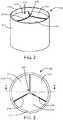
- the prosthetic heart valve 100includes a base 212 defining a substantially cylindrical passage 213 and a plurality of polymeric leaflets 214 disposed along the substantially cylindrical passage 213.
- Each polymeric leaflet 214includes a respective root portion 216 coupled to the base 212 and a respective edge portion 218 movable relative to the root portion 216 to coapt with the edge portions of the other polymeric leaflets along the coaptation region 220.
- the prosthetic heart valve 100can be any type of heart valve (e.g., a mitral valve or an aortic valve).
- the prosthetic heart valve 100is implanted (e.g., surgically or through transcatheter delivery) in a mammalian heart.
- the edge portions 218 of the leaflets 214amove into coaptation with one another in a closed position to substantially restrict fluid from flowing past the prosthetic heart valve 100 in a closed position.
- the edge portions 218 of the leaflets 214move away from one another to an open position permitting fluid to flow past the prosthetic heart valve 100. Movement of the leaflets 214 between the closed and open positions substantially approximates the hemodynamic performance of a healthy natural valve.
- FIG. 3shows a top view of the prosthetic heart valve 100.
- the base 212includes a frame 422 disposed in a polymer layer 424.
- the frame 422may not be disposed in a polymer layer.
- the respective root portions 216 of the leaflets 214can be attached to the base 212 using a mechanical mechanism, a fastener, sutures or can otherwise be sewn on.
- the polymer layer 424can be disposed between each of the leaflets 214 and the frame 422 such that the polymer layer 424 protects the leaflets 214 from inadvertent contact with the frame 422 (e.g., as can occur through eccentric deformation of the prosthetic heart valve 100 on a calcium deposit present at the implantation site).
- the frame 422is substantially cylindrical such that the outer surface of the base 212 is substantially cylindrical and the polymer layer 424 disposed on the frame 422 forms the substantially cylindrical passage 213.
- the frame 422can provide a radial force sufficient to at least partially secure the valve 100 in place at the implantation site.
- the frame 422is radially expandable from a collapsed position (e.g., for transcatheter delivery) to an expanded position (e.g., for positioning at the implantation site).
- the frame 422can be a self-expandable stent or a balloon-expandable stent.
- the framecan be formed of various materials.
- the framecan be formed of a metal, a polymer, a ceramic, a composite, or the like.
- the framecan be formed of a polymer and a metal oxide layer can be disposed over the polymeric frame.
- the metal oxide layercan be applied in various ways, including ALD techniques described herein.
- the frame 422is completely disposed in the polymer layer 424, with the polymer layer 424 forming a contoured outer surface of the valve 10. However, in some implementations, the frame 422 is partially disposed in the polymer layer 424. In certain implementations, the polymer layer 424 is applied to the frame 422 to form a substantially smooth inner and/or outer surface of the valve 100.
- the valve 100 and the leaflets 214have an upstream side 250 and a downstream side 252.
- valve leafletscan be integral with the frame and/or a polymer layer disposed over the frame.
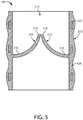
- FIG. 5a schematic cross-sectional view is shown of an artificial heart valve in accordance with various examples.
- the valve leaflets 214are integral with the polymer layer 424.
- the polymer layer 424can form a substantially continuous surface with the respective root portions 416 of the leaflets 214. This can reduce the likelihood of stress concentrations at the junction of the respective root portions 216 and the base 212.
- the root portions 216are secured to the polymer layer 224 and, thus, the base 212 without the use of sutures, the base 212 can be formed without support portions typically required on sutured valves.
- Thiscan facilitate formation of the prosthetic heart valve 100 with a lower overall height as compared to sutured valves. Such lower overall height can improve the hemodynamic performance of the prosthetic heart valve as compared to valves having larger overall heights.
- the lower overall height facilitated by the formation of the prosthetic heart valve 100 without suturescan improve the physiological performance of the prosthetic heart valve 100 as compared to valves having larger overall heights.
- the base 212can define an overall height of the prosthetic heart valve 100 and the height of the base 212 can be sized such that the coronary ostium is not covered by the prosthetic heart valve 100 at the implantation site. This can, for example, reduce the likelihood of disrupting normal electrical signaling in the heart.
- the base 212has an overall height of about 5 mm to about 20 mm, depending on the diameter of the cylindrical valve body.
- the polymeric leaflets 214each have a substantially uniform thickness along a length of the leaflet extending from each respective root portion 216 to the respective edge portion 218. In other examples the polymeric leaflets 214 have a thickness that varies along a length of the leaflet extending from each respective root portion 216 to the respective edge portion 218.
- the natural anatomical construction of a heart valveis such that there are anisotropic mechanical properties.
- the structure of the native leafletis a trilayer construct. On the side facing the ventricle, there is a layer of collagen and elastin fibers with a radial orientation (aligned from the wall of the supporting structure to the tip of the valve leaflet). In the fibrosa layer (the side facing the aorta) there is collagen but the fibers are oriented more circumferentially, which imparts characteristic flexibility and enables valve sealing.
- various parameters of the materials of the leaflets of the present disclosuresuch as stiffness, thickness, density, and the like can be varied along the leaflets 214 to substantially match the anisotropic mechanical properties of healthy, native leaflets.
- the flexural stiffness of the leaflete.g., leaflet 214) is less than 8 g/cm.
- FIG. 6is a schematic cross-sectional view of a portion of a valve leaflet in accordance with some examples herein as taken along line 6-6' of FIG. 4 .
- the valve leaflet 214includes a plurality of fibers 604. This view is provided by way of example and it will be appreciated that the actual orientation of fibers within the layer may be substantially more random than as shown in FIG. 6 , depending on the technique used for deposition of the fibers.
- the fibers 604form a fibrous matrix or fibrous layer 608.
- the fibrous layer 608can include a substantial number of pores 606 or voids. The density of the fibrous matrix is such that the void volume is between 1 and 75 percent of the total volume of the fibrous matrix.
- the density of the fibrous matrixis substantially uniform across the thickness of the leaflet. In some examples, the density of the fibrous matrix is asymmetric across the thickness of the leaflet. In some examples, the density of the fibrous matrix is greater on the upstream side of the valve leaflet than on the downstream side of the valve leaflet. In some examples the density of the fibrous matrix varies across the width of the leaflet.
- the thickness of the fibrous layer 608can vary. In some examples the fibrous layer 608 can be from about 0.002" (0.0508 mm) to about 0.02" (0.508 mm) thick. In some examples the fibrous layer 608 can be from about 0.003" (0.0762 mm) to about 0.015" (0.381 mm) thick.
- FIG. 7is a schematic cross-sectional view of a fiber 604 in accordance with various examples herein.
- the fiber 604can include a polymeric core 702 and a shell or coating 706.
- the polymeric core 702can have a thickness or diameter 704 in the ranges described below. However, in some examples, the diameter 704 is from about 10 nanometers to about 10 micrometers. Exemplary materials for the polymeric core 702 of fibers are described in greater detail below.
- the coating (or shell) 706can have a thickness 708 of about 3 to about 30 nanometers. In some examples, the coating 706 is greater than or equal to about 2, 3, 4, 5, 6, 8, 10, 12, 14, 16, 18, 20, 22, 24, 26 or 28 nanometers. In some examples, the coating 706 is less than or equal to about 30, 28, 26, 24, 22, 20, 18, 16, 14, 12, 10, 8 or 6 nanometers. In some examples these thicknesses can apply to the sum of all coatings applied to the polymeric core. In some examples these thickness can apply to individual layers making up the entire coating on the polymer core. Exemplary materials for the coating 706 are described in greater detail below.
- the fibercan include more than one layer (or coating layer) disposed over the polymer core.
- FIG. 8a schematic cross-sectional view of a fiber 604 in accordance with various examples is shown.
- the fiber 604can include a polymeric core 702, and a shell or coating including a first layer 802 disposed over the polymeric core and a second layer 804 disposed over the first layer 802.
- the first layer 802 and second layer 804can be formed of different materials.
- at least one of the first and second layerscan be formed of a metal oxide and at least one of the first and second layers can be formed of a polymer.
- the fiber 604can include a polymeric core 702, a first layer 902 disposed over the polymeric core, a second layer 904 disposed over the first layer 902, and a third layer disposed over the second layer 904.
- the first layer 902, second layer 904 and third layer 906can be formed of different materials. In some examples, one or more of the layers that are not contacting each other can be formed of the same materials. While FIG. 9 illustrates three coating layers, it will be appreciated that in various examples herein even more than three coating layers can be used. In some examples, there are from 1 to 9 coating layers. In some examples, there are from 2 to 5 coating layers.
- FIG. 10is a schematic cross-sectional view of a portion of a valve leaflet 214 in accordance with various examples herein.
- the valve leaflet 214can include a first zone or portion 1004 and a second zone or portion 1002.
- the first zone or portion 1004can have a first thickness 1008 and the second zone or portion 1002 can have a second thickness 1006.
- the first thickness 1008 and the second thickness 1006can either be the same or different.
- FIG. 11is a schematic cross-sectional view of a portion of a valve leaflet 214 in accordance with various examples herein.
- the valve leaflet 214can include a first zone or portion 1106, a second zone or portion 1104 and a third zone or portion 1102.
- the first zone or portioncan be the same as the third zone or portion, while the second zone or portion can be different.
- all of the first zone, second zone, and third zonecan be different from one another.
- Fibers hereincan be formed of various materials including, specifically, polymers.
- the fiberscan include a polymeric material such as a polymer, or a blend of polymers.
- a "polymer”is any macromolecule composed of two or more monomers, and includes dimers, trimers, tetramers, etc.
- a "monomer”is a polymerizable molecule.
- the polymeric materialscomprise polymer molecules having a median number of monomers that numbers in the tens (10 to 99), in the hundreds (100 to 999), in the thousands (1,000 to 9,999), or in the tens of thousands (10,000 to 99,999) as well as a mixture of polymers having different median numbers of monomers.
- the polymeric materialscan comprise polymer molecules having a median number of monomers that is 100,000 or more.
- Polymers hereincan be crosslinked or uncrosslinked, linear or branched, natural or synthetic, thermoplastic or thermosetting, and may be biostable, biodegradable, bioabsorbable, biodisintegrable, or dissolvable.
- Exemplary polymerscan include those that are capable of being electrospun.
- Exemplary polymerscan include, but are not limited to, poly(ethylene oxide), polyethylene, polyisobutylene polyurethane (PIBU), poly(styrene-block-isobutylene-block-styrene (SIBS), polypropylene, polystyrene, polyvinylchloride, polyisobutylene (PIB), poly(styrene) polyurethanes, polyvinylidene difluoride, poly(methyl methacrylate), polyethylene glycol, polyanilines, polypyrroles, polythiophenes, polyphenols, polyacetylenes, polyphenylenes, polyacrylonitriles, polylactic acids, polycaprolactone, polyglycolides, polyvinyl acetates, cellulose acetate and copolymers including one or more of these.
- Polymerscan also include biological polymers such as chitosan, proteins, carbohydrates,
- the fiberscan be formed in various ways.
- the fiberscan be formed through an electrospinning (or electrostatic fiber formation or electrospraying) process.
- Electrospinningis a fiber production method which uses electric force to draw charged threads of polymer solutions or polymer melts. When a sufficiently high voltage is applied to a liquid droplet, the body of the liquid becomes charged, and electrostatic repulsion counteracts the surface tension and the droplet is stretched. At a critical point a stream of liquid erupts from the surface. This point of eruption is known as the Taylor cone. If the molecular cohesion of the liquid is sufficiently high, stream breakup does not occur and a charged liquid jet is formed.
- the mode of current flowchanges from ohmic to convective as the charge migrates to the surface of the fiber.
- the jetis then elongated by a whipping process caused by electrostatic repulsion initiated at small bends in the fiber, until it is finally deposited on the grounded collector.
- the elongation and thinning of the fiber resulting from this bending instabilityleads to the formation of substantially uniform fibers with nanometer-scale diameters.
- the two principal parameters that control behavior of the Taylor coneare the viscosity and voltage at the nozzle.
- Exemplary methods of creating ultra-thin fibers for use in creating a fiber meshworkinvolve electro-spinning. Electro-spinning methods are described in Shin, Hohman, Brenner, and Rutledge, "Experimental Characterization of electrospinning: the electrically forced jet and instabilities", Polymer 42, 9955-9967, (2001 ). Fibers that are micrometers in diameter can be created by melt spinning or gel spinning, i.e., they are formed out of a gel or a molten melt.
- a particularly exemplary method of depositing the fiber meshworkis to use a process referred to as flow-limited field-injection electrostatic spraying (FFESS).
- FFESSis a form of electrospraying which offers a very high degree of control over shape and flow regimes, and which allows spinning a fiber-meshwork on top of a medical device, such as an endoprosthesis, with a glass spray nozzle. The nozzle generates a charge at the liquid meniscus that enables successful electrospray.
- FFESSelectro-spraying
- the FFESS method for electro-spinningcreates a fiber meshwork in which the one or more fibers have a highly controlled fiber diameter.
- the diameter of the fibers formed during the spinning processcan be controlled.
- a further advantage of FFESSis thus that, because of the high degree of control of the fiber diameter, if the weight of the fiber meshwork as well as the density of the polymer material for a given fiber diameter are known, the total surface area of the meshwork can be precisely calculated.
- the surface area of a fiber of diameter d, and of length 1assuming a uniform perfectly cylindrical constant cross-section along its length, is ⁇ d1, ignoring contributions from the ends of the fibers.
- FFESSis further described in "Controlling surface nano-structure using flow-limited field-injection electrostatic spraying (FFESS) of poly(d,l-lactide-co-glycolide)", Berkland, Pack, and Kim, Biomaterials, 25: 5649-5658, (2004 ) and U.S. Patent Application Publication No. 2004/0022939 .
- Solvents used during the electrospinning processcan affect various aspects such as fiber morphology.
- Solvents usedcan include, but are not limited to, dichloromethane, chloroform, methanol, tetrahydrofuran, ethyl acetate, ethanol, methyl ethyl ketone, dichloroethane, water, dimethylformamide, and combinations including one or more of these.
- the solution conductivitycan be manipulated in order to impact fiber diameter and morphology.
- various saltsincluding but not limited to sodium chloride and phosphate salts
- fiberscan be formed, deposited and/or formed into components of a valve in other ways.
- fiberscan be woven.
- fiberscan be woven to form a fibrous matrix forming at least part of a valve leaflet. Many different weaving techniques are contemplated herein.
- Fibers hereincan include, but are not limited to, spinning, centrifugal spinning (force spinning), drawing, template synthesis, phase separation, melt-blowing, self-assembly and the like.
- Diameters of the polymeric core of fibers used hereincan be greater than about 5, 10, 20, 30, 50, 100, 150, 200, 250, 500, 750, or 1000 nanometers. In some examples the diameter of the polymeric core of fibers herein can be greater than about 1, 2, 3, 4, 5, 6, 7, or 8 micrometers. Diameters of the polymeric core of fibers used herein can be less than about 20, 18, 16, 14, 12, 10, 8, 6, 4, 2 or 1 micrometer. In some examples, diameters of the polymeric core of fibers used herein can be less than about 1000, 900, 800, 700, 600, 500, 400, 200, 100, or 50 nanometers.
- Diameters of the polymeric core of fibers used hereincan be within a range wherein any of the foregoing numbers can serve as the lower or upper bound of the range, provided that the lower bound is less than the upper bound.
- the average diameter of the polymeric corecan be from about 10 nanometers to about 10 micrometers.
- Examples hereincan include fibers wherein a coating or layer of material is disposed on a polymeric fiber.
- the coating or layercan completely encapsulate the fiber in that it can surround the fiber on all sides.
- the thickness of the coating or layercan be approximately equal on all sides.
- the coating or layercan include various materials.
- Exemplary materialscan include, but are not limited to, metal oxides, nitrides, carbides, sulfides, and fluorides.
- a thin film deposition techniqueis used.
- Exemplary techniquescan include vapor deposition techniques such as physical vapor deposition (PVD), electron beam physical vapor deposition (EB-PVD), hot-filament chemical vapor deposition (HFCVD), hot-filament metal oxide deposition (HFMOD), plasma-assisted chemical vapor deposition, aerosol-chemical vapor deposition (ACVD).
- PVDphysical vapor deposition
- EB-PVDelectron beam physical vapor deposition
- HFCVDhot-filament chemical vapor deposition
- HFMODhot-filament metal oxide deposition
- plasma-assisted chemical vapor depositionaerosol-chemical vapor deposition
- the materialscan be deposited using a technique known as atomic layer deposition (ALD).
- ALDatomic layer deposition
- Atomic layer depositionis a thin film deposition method in which a film is grown on a substrate by exposing its surface to alternate gaseous species (typically referred to as precursors).
- precursorstypically referred to as alternate gaseous species
- the precursorsare not present simultaneously in the reactor, but they are inserted as a series of sequential, non-overlapping pulses. In each of these pulses the precursor molecules react with the surface in a self-limiting way, so that the reaction terminates once all the reactive sites on the surface are consumed. Consequently, the maximum amount of material deposited on the surface after a single exposure to all of the precursors (a so-called ALD cycle) is determined by the nature of the precursor-surface interaction. By varying the number of cycles it is possible to grow materials uniformly and with high precision on arbitrarily complex and large substrates.
- Deposited metal oxidescan include, but are not limited to, aluminum oxide (Al 2 O 3 ), titanium dioxide (TiO 2 ), silicon dioxide (SiO 2 ) and the like.
- the metal oxidecan be a noble metal oxide such as ruthenium oxide, rhodium oxide, palladium oxide, silver oxide, osmium oxide, iridium oxide, platinum oxide and gold oxide.
- the coatingcan be a nanolaminate including a plurality of thin individual layers that alternate with each other to form a multilayer stack having a total of at least 4 layers.
- the nanolaminatecan have at least 8 or at least 10 layers.
- the individual layersmay be metal or ceramic layers.
- suitable metals and ceramics for the individual layers of the nanolaminateinclude Al 2 O 3 , SiO 2 , Si 3 N 4 , TiO 2 , BN, ZnO, W, IrOx, B 2 O 3 , CO 2 O 3 , Cr 2 O 3 , Fe 2 O 3 , Ga 2 O 3 , HfO 2 , In 2 O 3 , MgO, Nb 2 O 5 , NiO, Pd, Pt, SnO 2 , Ta 2 O 5 , TaN, TaN, AlN, TiCrO, TiN, VO 2 , WO 3 , ZnO, (Ta/Al)N, (Ti/Al)N, (Al/Zn)O, ZnS, ZnSe, ZrO, SC 2 O 3 , Y 2 O 3 , Ca 10 (PO 4 )(OH) 2 , rare earth oxides, and combinations thereof.
- one of the layersmay be Al 2 O 3 , TiO 2 , TiO
- useful nanolaminatesinclude structures in which (a) one layer is Al 2 O 3 and the other layer is Ta 2 O 5 ; (b) one layer is Al 2 O 3 and the other layer is W; and (c) one layer is Al 2 O 3 and the other layer is TiO 2 .
- the individual layersmay be amorphous or crystalline.
- the layers of the nanolaminatecan be formed by atomic layer deposition.
- Atomic layer depositionis a self-limiting deposition process in which the growth of the monolayer being deposited stops after a certain point (e.g., because of thermodynamic conditions or the bonding nature of the molecules involved), even though sufficient quantities of deposition materials are still available. Atomic layer deposition creates layers that are smooth and uniform
- a TiO 2 layercan be formed by atomic layer deposition by reacting titanium tetrachloride (TiCl 4 ) and water (H 2 O) according to the following two sequential half-reactions: :Mg--OH + TiCl 4 (g) ⁇ :Mg--O--TiCl 3 + HCl (A) :Mg--O--TiCl 3 + 3 H 2 O ⁇ :Mg--O--Ti(OH) 3 + 3HCl (B) with :Mg--OH and :Mg--O--TiCl 3 being the surface species.
- TiCl 4titanium tetrachloride
- H 2 Owater
- Titanium tetrachloride and other precursor materials for forming a titanium oxide coatingcan be obtained from Sigma-Aldrich Corporation of St. Louis, Mo.
- the choice of deposition temperatureis selected based upon the desired crystalline form of the TiO 2 layer.
- the crystalline anatase form of titanium oxidepreferentially develops at relatively high deposition temperatures (e.g., greater than 250° C.), whereas the amorphous form of titanium oxide preferentially develops at relatively low deposition temperatures (e.g., less than 150° C.).
- Aluminum oxidecan be deposited by atomic layer deposition using trimethylaluminum and water as the precursors, and a deposition temperature as low as 50° C.
- suitable reactants and reactant conditions for atomic layer deposition to form layered structuresare described, for example, in (a) Fabreguette et al., "X-ray mirrors on flexible polymer substrates fabricated by atomic layer deposition," Thin Solid Films 515:7177-7180 (2007 ); (b) Szeghalmi et al., "All dielectric hard x-ray mirror by atomic layer deposition," Appl. Phys. Lett.
- the thickness of the coating or layercan vary.
- the coatingis greater than or equal to about 2, 3, 4, 5, 6, 8, 10, 12, 14, 16, 18, 20, 22, 24, 26 or 28 nanometers.
- the coatingis less than or equal to about 30, 28, 26, 24, 22, 20, 18, 16, 14, 12, 10, 8 or 6 nanometers.
- the total coatingcan have a thickness of about 3 to about 30 nanometers.
- individual sublayerscan have a thickness of about 1 to about 30 nanometers.
- a method of making a valveis included.
- the methodcan specifically include depositing polymeric fibers in a layer to form a fibrous matrix.
- the methodcan further include cutting the fibrous matrix into the shape of a valve leaflet.
- the methodcan further include applying a layer of a metal oxide onto the polymeric fibers using a gas phase deposition technique.
- the methodcan further include attaching the valve leaflet onto a frame.
- the valve leafletcan be attached in various way including through mechanical fixation, adhesives, welding, and the like.
- the valve leafletcan be sewn on.
- a method of making a valveis included.
- the methodcan specifically include depositing polymeric fibers into a mold in a layer to form a fibrous matrix.
- the methodcan include removing the fibrous matrix from the mold.
- the methodcan include applying a layer of a metal oxide onto the polymeric fibers using a gas phase deposition technique.
- a method of making a valvecan include depositing polymeric fibers onto a frame to form a valve leaflet and applying a layer of a metal oxide onto the polymeric fibers using a gas phase deposition technique.
- the phrase “configured”describes a system, apparatus, or other structure that is constructed or configured to perform a particular task or adopt a particular configuration to.
- the phrase “configured”can be used interchangeably with other similar phrases such as arranged and configured, constructed and arranged, constructed, manufactured and arranged, and the like.
Landscapes
- Health & Medical Sciences (AREA)
- Engineering & Computer Science (AREA)
- Chemical & Material Sciences (AREA)
- Oral & Maxillofacial Surgery (AREA)
- Veterinary Medicine (AREA)
- General Health & Medical Sciences (AREA)
- Transplantation (AREA)
- Public Health (AREA)
- Life Sciences & Earth Sciences (AREA)
- Animal Behavior & Ethology (AREA)
- Cardiology (AREA)
- Biomedical Technology (AREA)
- Medicinal Chemistry (AREA)
- Dermatology (AREA)
- Epidemiology (AREA)
- Vascular Medicine (AREA)
- Heart & Thoracic Surgery (AREA)
- Inorganic Chemistry (AREA)
- Textile Engineering (AREA)
- Organic Chemistry (AREA)
- Polymers & Plastics (AREA)
- Chemical Kinetics & Catalysis (AREA)
- Manufacturing & Machinery (AREA)
- Prostheses (AREA)
Description
- This application is being filed as a PCT International Patent application on May 12, 2017 in the name of Boston Scientific Scimed, Inc., a U.S. national corporation, applicant for the designation of all countries and Jan Weber, a U.S. Citizen, and Haiying Zhou, a U.S. Citizen, and Bruce R. Forsyth, a U.S. Citizen, inventors for the designation of all countries, and claims priority to
U.S. Provisional Application No. 62/338,722, filed May 19, 2016 - Aspects herein relate to prosthetic valves, valve leaflets and related methods. More specifically, aspects herein relates to fibrous valve leaflets and valves including the same.
- Heart function can be significantly impaired when a heart valve is not functioning properly. Potential causes for heart valve malfunction include dilation of an annulus around the valve, ventricular dilation, and a prolapsed or misshapen valve leaflet. When the heart valve is unable to close properly, the blood within a heart chamber can regurgitate, or leak backwards through the valve.
- Valve regurgitation may be treated by replacing or repairing a diseased valve, such as an aortic valve. Surgical valve replacement is one method for treating the diseased valve, but other less invasive methods of treatments are also available to many patients. Minimally invasive methods of treatment, such as transcatheter aortic valve replacement (TAVR), generally involve the use of delivery catheters that are delivered through arterial passageways or other anatomical routes into the heart to replace the diseased valve with an implantable prosthetic heart valve. Leaflets of such valves have been formed from various materials including synthetic materials and animal tissues.
US2007232169 A1 discloses medical devices that contain at least one multi-component polymeric fiber. The multi-component polymeric fiber further contains at least two components of differing composition. - The prosthetic valve of the invention is defined in
claim 1 and the method of making such a valve in claim 15. Aspects herein include prosthetic valves, valve leaflets and related methods. In an example, a prosthetic valve is included. The prosthetic valve includes a plurality of leaflets. The leaflets have a root portion and an edge portion substantially opposite the root portion and movable relative to the root portion to coapt with a respective edge portion of at least one of the other leaflets of the plurality of leaflets. The leaflets include a fibrous matrix, the fibrous matrix including polymeric fibers having an average diameter of about 10 nanometers to about 10 micrometers. A coating surrounds the polymeric fibers within the fibrous matrix. The coating has a thickness of about 3 to about 30 nanometers. The coating is formed of a material selected from the group consisting of a metal oxide, a nitride, a carbide, a sulfide, or fluoride. - In some examples, the leaflets each have a thickness between an upstream side and a downstream side of about 0.003" (0.0762 mm) to about 0.015" (0.381 mm).
- The polymeric fibers can include a polymer selected from the group consisting of poly(ethylene oxide), polyethylene, polyisobutylene polyurethane (PIBU), poly(styrene-block-isobutylene-block-styrene (SIBS), polypropylene, polystyrene, polyvinylchloride, polyisobutylene (PIB), poly(styrene) polyurethanes, polyvinylidene difluoride, poly(methyl methacrylate), polyethylene glycol, polyanilines, polypyrroles, polythiophenes, polyphenols, polyacetylenes, polyphenylenes, polyacrylonitriles, polylactic acids, polycaprolactone, polyglycolides, polyvinyl acetates, cellulose acetate, chitosan, proteins, carbohydrates and copolymers including one or more of these. In some examples, the valve can include a synthetic polymer.
- The coating material can include a metal oxide selected from the group consisting of aluminum oxide, titanium dioxide, silicon dioxide, ruthenium oxide, rhodium oxide, palladium oxide, silver oxide, osmium oxide, iridium oxide, platinum oxide and gold oxide. In some examples, the metal oxide comprising aluminum oxide (Al2O3).
In addition, in some examples the coating surrounding the polymeric fibers prevents the penetration of water there through. In addition or alternatively, the coating surrounding the polymeric fibers can include a polymeric layer. In addition or alternatively,
the coating surrounding the polymeric fibers can be a multilaminate layer including metal oxide and polymeric sublayers. - In various examples, the strength of the polymeric fibers in the fibrous matrix after implantation and exposure to thein vivo environment is greater than an otherwise identical fibrous matrix lacking the metal oxide coating. In various examples,
the fibrous matrix can include a void volume of between 1 and 75 %. In various examples, the density of the fibrous matrix is substantially uniform across the thickness of the leaflet. In addition or alternatively, the density of the fibrous matrix can be asymmetric across the thickness of the leaflet. In addition or alternatively, the density of the fibrous matrix is greater on the upstream side of the valve leaflet than on the downstream side of the valve leaflet. In addition or alternatively, the density of the fibrous matrix varies across the width of the leaflet. - In various examples, the valve can include a frame, wherein the leaflets are attached to the frame. In addition or alternatively, the leaflets can be sewn to the frame. In addition or alternatively, the leaflets can be integral with the frame. In addition, or alternatively, the frame can be expandable. In addition, or alternatively, the valve can be a TAVI valve. In addition, or alternatively, the leaflets can assume an open position to allow the flow of blood through the valve and a closed position to block the flow of blood through the valve. In addition, or alternatively, the flexural stiffness of the leaflet is less than 8 g/cm.
- In an example, a method of making a valve is included. The method can include depositing polymeric fibers in a layer to form a fibrous matrix, cutting the fibrous matrix into the shape of a valve leaflet and applying a layer of a metal oxide onto the polymeric fibers using a gas phase deposition technique. In various aspects, the method can further include attaching the valve leaflet onto a frame. In various examples, the gas phase deposition technique comprising atomic layer deposition (ALD). In addition or alternatively, depositing the polymeric fibers includes electrospinning. In addition or alternatively, depositing the polymeric fibers includes weaving.
- In various examples, the average diameter of the polymeric fibers is about 10 nanometers to about 10 micrometers. In addition or alternatively, the average thickness of the metal oxide layer is about 3 to about 30 nanometers.
- In an example, a method of making a valve is included having the steps of depositing polymeric fibers into a mold in a layer to form a fibrous matrix, removing the fibrous matrix from the mold and applying a layer of a metal oxide onto the polymeric fibers using a gas phase deposition technique.
- In an example, a method of making a valve is included having the steps of depositing polymeric fibers onto a frame to form a valve leaflet and applying a layer of a metal oxide onto the polymeric fibers using a gas phase deposition technique.
- This summary is an overview of some of the teachings of the present application and is not intended to be an exclusive or exhaustive treatment of the present subject matter. Further details are found in the detailed description and appended claims. Other aspects will be apparent to persons skilled in the art upon reading and understanding the following detailed description and viewing the drawings that form a part thereof, each of which is not to be taken in a limiting sense. The scope herein is defined by the appended claims.
- Aspects may be more completely understood in connection with the following drawings, in which:
FIG. 1 is a schematic view a prosthetic heart valve within a human body.FIG. 2 is a schematic perspective view of a prosthetic heart valve in accordance with various examples herein.FIG. 3 is a schematic top view of a prosthetic heart valve.FIG. 4 is a schematic cross-sectional view of an artificial heart valve as taken along line 4-4' ofFIG. 3 .FIG. 5 is a schematic cross-sectional view of an artificial heart valve in accordance with various examples.FIG. 6 is a schematic cross-sectional view of a portion of a valve leaflet in accordance with some examples herein.FIG. 7 is a schematic cross-sectional view of a fiber in accordance with various examples herein.FIG. 8 is a schematic cross-sectional view of a fiber in accordance with various examples herein.FIG. 9 is a schematic cross-sectional view of a fiber in accordance with various examples herein.FIG. 10 is a schematic cross-sectional view of a portion of a valve leaflet in accordance with various examples herein.FIG. 11 is a schematic cross-sectional view of a portion of a valve leaflet in accordance with various examples herein.- While examples are susceptible to various modifications and alternative forms, specifics thereof have been shown by way of example and drawings, and will be described in detail. It should be understood, however, that the scope herein is not limited to the particular examples described. On the contrary, the intention is to cover modifications, equivalents, and alternatives falling within the spirit and scope herein.
- The examples described herein are not intended to be exhaustive or to limit the scope to the precise forms disclosed in the following detailed description. Rather, the examples are chosen and described so that others skilled in the art can appreciate and understand the principles and practices.
- The publications and patents disclosed herein are provided solely for their disclosure. Nothing herein is to be construed as an admission that the inventors are not entitled to antedate any publication and/or patent, including any publication and/or patent cited herein.
- Leaflets of such prosthetic valves can be formed from various materials including synthetic materials and animal tissues. Synthetic leaflets should be designed to withstand repetitive stresses over a substantial length of time.
- Electrospun and/or woven fibers can be formed into a layer and can successfully withstand such repetitive stresses. However, partly due to their small diameter which effectively increases the surface area to mass ratio, some fibers can degrade over time in thein vivo environment.
- Examples herein include valve leaflets formed with small diameter fibers, such as electrospun fibers and/or woven fibers, that are coated with a layer (such as a metal oxide layer) that prevents degradation of the fibersin vivo.
FIG. 1 is an illustration of aprosthetic heart valve 100 provided herein within aheart 102 of ahuman body 105. The heart has four heart valves: a pulmonary valve, a tricuspid valve, an aortic valve and a mitral valve. The heart valves allow blood to pass through the heart and into major blood vessels connected to the heart, for example, the aorta and pulmonary artery.Prosthetic heart valve 100 ofFIG. 1 is an aortic prosthetic heart valve that can be surgically implanted or delivered through blood vessels using a delivery device orcatheter 110. Thedelivery catheter 110 can be inserted into a femoral, subclavian, or an aortic incision during a transcatheter aortic valve replacement (TAVR) procedure. Once inserted, thedelivery catheter 110 can deliver theprosthetic heart valve 100 to the desired location within the anatomy and release theheart valve 100 at a desired implantation site. AlthoughFIG. 1 showsprosthetic heart valve 100 replacing an aortic valve, in some cases,prosthetic heart valve 100 can be a replacement for another type of heart valve (e.g., a mitral valve or a tricuspid valve). In some examples the heart valve is specifically a TAVI (transcatheter aortic valve implantation) valve.- Referring to
FIG. 2 theprosthetic heart valve 100 includes a base 212 defining a substantiallycylindrical passage 213 and a plurality ofpolymeric leaflets 214 disposed along the substantiallycylindrical passage 213. Eachpolymeric leaflet 214 includes arespective root portion 216 coupled to thebase 212 and arespective edge portion 218 movable relative to theroot portion 216 to coapt with the edge portions of the other polymeric leaflets along thecoaptation region 220. It should be appreciated that theprosthetic heart valve 100 can be any type of heart valve (e.g., a mitral valve or an aortic valve). - In use, the
prosthetic heart valve 100 is implanted (e.g., surgically or through transcatheter delivery) in a mammalian heart. Theedge portions 218 of the leaflets 214a move into coaptation with one another in a closed position to substantially restrict fluid from flowing past theprosthetic heart valve 100 in a closed position. Theedge portions 218 of theleaflets 214 move away from one another to an open position permitting fluid to flow past theprosthetic heart valve 100. Movement of theleaflets 214 between the closed and open positions substantially approximates the hemodynamic performance of a healthy natural valve.FIG. 3 shows a top view of theprosthetic heart valve 100. - Referring now to
FIG. 4 , a cross-sectional view of elements of a prosthetic heart valve are shown as taken along line 4-4' ofFIG. 3 . Thebase 212 includes aframe 422 disposed in apolymer layer 424. However, in other examples, theframe 422 may not be disposed in a polymer layer. In some examples, therespective root portions 216 of theleaflets 214 can be attached to the base 212 using a mechanical mechanism, a fastener, sutures or can otherwise be sewn on. Additionally or alternatively, thepolymer layer 424 can be disposed between each of theleaflets 214 and theframe 422 such that thepolymer layer 424 protects theleaflets 214 from inadvertent contact with the frame 422 (e.g., as can occur through eccentric deformation of theprosthetic heart valve 100 on a calcium deposit present at the implantation site). - The
frame 422 is substantially cylindrical such that the outer surface of thebase 212 is substantially cylindrical and thepolymer layer 424 disposed on theframe 422 forms the substantiallycylindrical passage 213. Theframe 422 can provide a radial force sufficient to at least partially secure thevalve 100 in place at the implantation site. In some implementations, theframe 422 is radially expandable from a collapsed position (e.g., for transcatheter delivery) to an expanded position (e.g., for positioning at the implantation site). For example, theframe 422 can be a self-expandable stent or a balloon-expandable stent. - The frame can be formed of various materials. By way of example, the frame can be formed of a metal, a polymer, a ceramic, a composite, or the like. In some examples, the frame can be formed of a polymer and a metal oxide layer can be disposed over the polymeric frame. The metal oxide layer can be applied in various ways, including ALD techniques described herein.
- The
frame 422 is completely disposed in thepolymer layer 424, with thepolymer layer 424 forming a contoured outer surface of the valve 10. However, in some implementations, theframe 422 is partially disposed in thepolymer layer 424. In certain implementations, thepolymer layer 424 is applied to theframe 422 to form a substantially smooth inner and/or outer surface of thevalve 100. Thevalve 100 and theleaflets 214 have anupstream side 250 and adownstream side 252. - In some examples the valve leaflets can be integral with the frame and/or a polymer layer disposed over the frame. Referring now to
FIG. 5 , a schematic cross-sectional view is shown of an artificial heart valve in accordance with various examples. In this view, thevalve leaflets 214 are integral with thepolymer layer 424. Thepolymer layer 424 can form a substantially continuous surface with the respective root portions 416 of theleaflets 214. This can reduce the likelihood of stress concentrations at the junction of therespective root portions 216 and thebase 212. - In this particular embodiment, the
root portions 216 are secured to the polymer layer 224 and, thus, thebase 212 without the use of sutures, the base 212 can be formed without support portions typically required on sutured valves. This can facilitate formation of theprosthetic heart valve 100 with a lower overall height as compared to sutured valves. Such lower overall height can improve the hemodynamic performance of the prosthetic heart valve as compared to valves having larger overall heights. - Additionally or alternatively, the lower overall height facilitated by the formation of the
prosthetic heart valve 100 without sutures can improve the physiological performance of theprosthetic heart valve 100 as compared to valves having larger overall heights. For example, the base 212 can define an overall height of theprosthetic heart valve 100 and the height of the base 212 can be sized such that the coronary ostium is not covered by theprosthetic heart valve 100 at the implantation site. This can, for example, reduce the likelihood of disrupting normal electrical signaling in the heart. In some implementations, thebase 212 has an overall height of about 5 mm to about 20 mm, depending on the diameter of the cylindrical valve body. - In some examples the
polymeric leaflets 214 each have a substantially uniform thickness along a length of the leaflet extending from eachrespective root portion 216 to therespective edge portion 218. In other examples thepolymeric leaflets 214 have a thickness that varies along a length of the leaflet extending from eachrespective root portion 216 to therespective edge portion 218. - The natural anatomical construction of a heart valve is such that there are anisotropic mechanical properties. The structure of the native leaflet is a trilayer construct. On the side facing the ventricle, there is a layer of collagen and elastin fibers with a radial orientation (aligned from the wall of the supporting structure to the tip of the valve leaflet). In the fibrosa layer (the side facing the aorta) there is collagen but the fibers are oriented more circumferentially, which imparts characteristic flexibility and enables valve sealing. It should be appreciated that various parameters of the materials of the leaflets of the present disclosure such as stiffness, thickness, density, and the like can be varied along the
leaflets 214 to substantially match the anisotropic mechanical properties of healthy, native leaflets. In some examples, the flexural stiffness of the leaflet (e.g., leaflet 214) is less than 8 g/cm. FIG. 6 is a schematic cross-sectional view of a portion of a valve leaflet in accordance with some examples herein as taken along line 6-6' ofFIG. 4 . Thevalve leaflet 214 includes a plurality offibers 604. This view is provided by way of example and it will be appreciated that the actual orientation of fibers within the layer may be substantially more random than as shown inFIG. 6 , depending on the technique used for deposition of the fibers. Thefibers 604 form a fibrous matrix orfibrous layer 608. Thefibrous layer 608 can include a substantial number ofpores 606 or voids.
The density of the fibrous matrix is such that the void volume is between 1 and 75 percent of the total volume of the fibrous matrix. In some examples, the density of the fibrous matrix is substantially uniform across the thickness of the leaflet. In some examples, the density of the fibrous matrix is asymmetric across the thickness of the leaflet. In some examples, the density of the fibrous matrix is greater on the upstream side of the valve leaflet than on the downstream side of the valve leaflet. In some examples the density of the fibrous matrix varies across the width of the leaflet.- The thickness of the
fibrous layer 608 can vary. In some examples thefibrous layer 608 can be from about 0.002" (0.0508 mm) to about 0.02" (0.508 mm) thick. In some examples thefibrous layer 608 can be from about 0.003" (0.0762 mm) to about 0.015" (0.381 mm) thick. FIG. 7 is a schematic cross-sectional view of afiber 604 in accordance with various examples herein. Thefiber 604 can include apolymeric core 702 and a shell orcoating 706. Thepolymeric core 702 can have a thickness ordiameter 704 in the ranges described below. However, in some examples, thediameter 704 is from about 10 nanometers to about 10 micrometers. Exemplary materials for thepolymeric core 702 of fibers are described in greater detail below.- If the coating layer(s) on the polymeric fiber are too thick, the flexibility of the fiber can be adversely impacted. If the coating layer(s) are too thin, it will be ineffective to prevent migration of water and other components and therefore ineffective to prevent the degradation of the fibers. The coating (or shell) 706 can have a
thickness 708 of about 3 to about 30 nanometers. In some examples, thecoating 706 is greater than or equal to about 2, 3, 4, 5, 6, 8, 10, 12, 14, 16, 18, 20, 22, 24, 26 or 28 nanometers. In some examples, thecoating 706 is less than or equal to about 30, 28, 26, 24, 22, 20, 18, 16, 14, 12, 10, 8 or 6 nanometers. In some examples these thicknesses can apply to the sum of all coatings applied to the polymeric core. In some examples these thickness can apply to individual layers making up the entire coating on the polymer core. Exemplary materials for thecoating 706 are described in greater detail below. - In some examples, the fiber can include more than one layer (or coating layer) disposed over the polymer core. Referring now to
FIG. 8 , a schematic cross-sectional view of afiber 604 in accordance with various examples is shown. Thefiber 604 can include apolymeric core 702, and a shell or coating including afirst layer 802 disposed over the polymeric core and asecond layer 804 disposed over thefirst layer 802. Thefirst layer 802 andsecond layer 804 can be formed of different materials. In some examples, at least one of the first and second layers can be formed of a metal oxide and at least one of the first and second layers can be formed of a polymer. - Referring now to
FIG. 9 , a schematic cross-sectional view of afiber 604 in accordance with various examples is shown. Thefiber 604 can include apolymeric core 702, afirst layer 902 disposed over the polymeric core, asecond layer 904 disposed over thefirst layer 902, and a third layer disposed over thesecond layer 904. Thefirst layer 902,second layer 904 andthird layer 906 can be formed of different materials. In some examples, one or more of the layers that are not contacting each other can be formed of the same materials. WhileFIG. 9 illustrates three coating layers, it will be appreciated that in various examples herein even more than three coating layers can be used. In some examples, there are from 1 to 9 coating layers. In some examples, there are from 2 to 5 coating layers. - In some examples different zones or portions of fibers can have different properties. By way of example, different zones or layers of fibers can have different densities of fibers (for example, as measured by void space). In some examples, different zones can be formed of polymeric fibers with different properties, such as different polymer compositions, different diameters, etc.
FIG. 10 is a schematic cross-sectional view of a portion of avalve leaflet 214 in accordance with various examples herein. Thevalve leaflet 214 can include a first zone orportion 1004 and a second zone orportion 1002. The first zone orportion 1004 can have afirst thickness 1008 and the second zone orportion 1002 can have asecond thickness 1006. Thefirst thickness 1008 and thesecond thickness 1006 can either be the same or different.FIG. 11 is a schematic cross-sectional view of a portion of avalve leaflet 214 in accordance with various examples herein. Thevalve leaflet 214 can include a first zone orportion 1106, a second zone orportion 1104 and a third zone orportion 1102. In some examples, the first zone or portion can be the same as the third zone or portion, while the second zone or portion can be different. In some examples, all of the first zone, second zone, and third zone can be different from one another. - Fibers herein can be formed of various materials including, specifically, polymers. The fibers can include a polymeric material such as a polymer, or a blend of polymers. A "polymer" is any macromolecule composed of two or more monomers, and includes dimers, trimers, tetramers, etc. A "monomer" is a polymerizable molecule. Typically, the polymeric materials comprise polymer molecules having a median number of monomers that numbers in the tens (10 to 99), in the hundreds (100 to 999), in the thousands (1,000 to 9,999), or in the tens of thousands (10,000 to 99,999) as well as a mixture of polymers having different median numbers of monomers. The polymeric materials can comprise polymer molecules having a median number of monomers that is 100,000 or more.
- Polymers herein can be crosslinked or uncrosslinked, linear or branched, natural or synthetic, thermoplastic or thermosetting, and may be biostable, biodegradable, bioabsorbable, biodisintegrable, or dissolvable.
- Exemplary polymers can include those that are capable of being electrospun. Exemplary polymers can include, but are not limited to, poly(ethylene oxide), polyethylene, polyisobutylene polyurethane (PIBU), poly(styrene-block-isobutylene-block-styrene (SIBS), polypropylene, polystyrene, polyvinylchloride, polyisobutylene (PIB), poly(styrene) polyurethanes, polyvinylidene difluoride, poly(methyl methacrylate), polyethylene glycol, polyanilines, polypyrroles, polythiophenes, polyphenols, polyacetylenes, polyphenylenes, polyacrylonitriles, polylactic acids, polycaprolactone, polyglycolides, polyvinyl acetates, cellulose acetate and copolymers including one or more of these. Polymers can also include biological polymers such as chitosan, proteins, carbohydrates, and the like.
- The fibers can be formed in various ways. In some examples, the fibers can be formed through an electrospinning (or electrostatic fiber formation or electrospraying) process. Electrospinning is a fiber production method which uses electric force to draw charged threads of polymer solutions or polymer melts. When a sufficiently high voltage is applied to a liquid droplet, the body of the liquid becomes charged, and electrostatic repulsion counteracts the surface tension and the droplet is stretched. At a critical point a stream of liquid erupts from the surface. This point of eruption is known as the Taylor cone. If the molecular cohesion of the liquid is sufficiently high, stream breakup does not occur and a charged liquid jet is formed. As the jet dries in flight, the mode of current flow changes from ohmic to convective as the charge migrates to the surface of the fiber. The jet is then elongated by a whipping process caused by electrostatic repulsion initiated at small bends in the fiber, until it is finally deposited on the grounded collector. The elongation and thinning of the fiber resulting from this bending instability leads to the formation of substantially uniform fibers with nanometer-scale diameters.
- The two principal parameters that control behavior of the Taylor cone are the viscosity and voltage at the nozzle. Exemplary methods of creating ultra-thin fibers for use in creating a fiber meshwork involve electro-spinning. Electro-spinning methods are described inShin, Hohman, Brenner, and Rutledge, "Experimental Characterization of electrospinning: the electrically forced jet and instabilities", Polymer 42, 9955-9967, (2001). Fibers that are micrometers in diameter can be created by melt spinning or gel spinning, i.e., they are formed out of a gel or a molten melt.
- A particularly exemplary method of depositing the fiber meshwork, is to use a process referred to as flow-limited field-injection electrostatic spraying (FFESS). FFESS is a form of electrospraying which offers a very high degree of control over shape and flow regimes, and which allows spinning a fiber-meshwork on top of a medical device, such as an endoprosthesis, with a glass spray nozzle. The nozzle generates a charge at the liquid meniscus that enables successful electrospray. The two principal differences between conventional electro-spraying (CES) and FFESS are first that FFESS sprays a polymer/solvent solution from a smooth glass capillary whereas CES uses a metal hypodermic needle, and second that FFESS uses a sharpened tungsten needle inside capillary, whereas CES has no analogous structure. The overall effect of the FFESS apparatus is to improve jet stability and uniformity of the polymer sprayed by FFESS relative to that from CES.
- Using the FFESS method for electro-spinning creates a fiber meshwork in which the one or more fibers have a highly controlled fiber diameter. In particular, as would be understood by one of ordinary skill in the art, by controlling the voltage, flow-rate, concentration of polymer in the spray fluid, the viscosity of the spray fluid, and the distance of the nozzle from the surface of the underlying structure (e.g., a mold or a valve frame, or a pocket within a valve frame), the diameter of the fibers formed during the spinning process can be controlled. For exemplary descriptions of the various factors, see, e.g., "Electrostatic Spinning and Properties of Ultrafine Fibers", Rutledge, et al., National Textile Center Annual Report, M01-D22, (November 2001). See also further description on the internet at www.che.vt.edu/Wilkes/electrospinning/electrspinning.html. It is also consistent with the fiber meshwork that the diameter of the fibers can be changed during deposition.
- A further advantage of FFESS is thus that, because of the high degree of control of the fiber diameter, if the weight of the fiber meshwork as well as the density of the polymer material for a given fiber diameter are known, the total surface area of the meshwork can be precisely calculated. Thus, the surface area of a fiber of diameter d, and of
length 1, assuming a uniform perfectly cylindrical constant cross-section along its length, is πd1, ignoring contributions from the ends of the fibers. FFESS is further described in "Controlling surface nano-structure using flow-limited field-injection electrostatic spraying (FFESS) of poly(d,l-lactide-co-glycolide)",Berkland, Pack, and Kim, Biomaterials, 25: 5649-5658, (2004) andU.S. Patent Application Publication No. 2004/0022939 . - Solvents used during the electrospinning process can affect various aspects such as fiber morphology. Solvents used can include, but are not limited to, dichloromethane, chloroform, methanol, tetrahydrofuran, ethyl acetate, ethanol, methyl ethyl ketone, dichloroethane, water, dimethylformamide, and combinations including one or more of these. In some examples, the solution conductivity can be manipulated in order to impact fiber diameter and morphology. By way of example, various salts (including but not limited to sodium chloride and phosphate salts) can be added with the solvent in order to change the solution conductivity.
- Beyond electrospinning, it will be appreciated that fibers can be formed, deposited and/or formed into components of a valve in other ways. For example, in some examples, fibers can be woven. In some examples fibers can be woven to form a fibrous matrix forming at least part of a valve leaflet. Many different weaving techniques are contemplated herein.
- Other techniques of forming fibers herein can include, but are not limited to, spinning, centrifugal spinning (force spinning), drawing, template synthesis, phase separation, melt-blowing, self-assembly and the like.
- Diameters of the polymeric core of fibers used herein can be greater than about 5, 10, 20, 30, 50, 100, 150, 200, 250, 500, 750, or 1000 nanometers. In some examples the diameter of the polymeric core of fibers herein can be greater than about 1, 2, 3, 4, 5, 6, 7, or 8 micrometers. Diameters of the polymeric core of fibers used herein can be less than about 20, 18, 16, 14, 12, 10, 8, 6, 4, 2 or 1 micrometer. In some examples, diameters of the polymeric core of fibers used herein can be less than about 1000, 900, 800, 700, 600, 500, 400, 200, 100, or 50 nanometers. Diameters of the polymeric core of fibers used herein can be within a range wherein any of the foregoing numbers can serve as the lower or upper bound of the range, provided that the lower bound is less than the upper bound. In some examples, the average diameter of the polymeric core can be from about 10 nanometers to about 10 micrometers.
- Examples herein can include fibers wherein a coating or layer of material is disposed on a polymeric fiber. In various examples, the coating or layer can completely encapsulate the fiber in that it can surround the fiber on all sides. In various examples, the thickness of the coating or layer can be approximately equal on all sides.
- The coating or layer can include various materials. Exemplary materials can include, but are not limited to, metal oxides, nitrides, carbides, sulfides, and fluorides.
- Materials can be deposited in various ways. In various examples, a thin film deposition technique is used. Exemplary techniques can include vapor deposition techniques such as physical vapor deposition (PVD), electron beam physical vapor deposition (EB-PVD), hot-filament chemical vapor deposition (HFCVD), hot-filament metal oxide deposition (HFMOD), plasma-assisted chemical vapor deposition, aerosol-chemical vapor deposition (ACVD).
- In some examples the materials can be deposited using a technique known as atomic layer deposition (ALD). Atomic layer deposition is a thin film deposition method in which a film is grown on a substrate by exposing its surface to alternate gaseous species (typically referred to as precursors). In contrast to chemical vapor deposition, the precursors are not present simultaneously in the reactor, but they are inserted as a series of sequential, non-overlapping pulses. In each of these pulses the precursor molecules react with the surface in a self-limiting way, so that the reaction terminates once all the reactive sites on the surface are consumed. Consequently, the maximum amount of material deposited on the surface after a single exposure to all of the precursors (a so-called ALD cycle) is determined by the nature of the precursor-surface interaction. By varying the number of cycles it is possible to grow materials uniformly and with high precision on arbitrarily complex and large substrates.
- Deposited metal oxides can include, but are not limited to, aluminum oxide (Al2O3), titanium dioxide (TiO2), silicon dioxide (SiO2) and the like. In some examples, the metal oxide can be a noble metal oxide such as ruthenium oxide, rhodium oxide, palladium oxide, silver oxide, osmium oxide, iridium oxide, platinum oxide and gold oxide.
- In some examples, multiple layers of materials can be deposited and those layers can differ from one another. In some examples, the coating can be a nanolaminate including a plurality of thin individual layers that alternate with each other to form a multilayer stack having a total of at least 4 layers. In some examples, the nanolaminate can have at least 8 or at least 10 layers. The individual layers may be metal or ceramic layers. Examples of suitable metals and ceramics for the individual layers of the nanolaminate include Al2O3, SiO2, Si3N4, TiO2, BN, ZnO, W, IrOx, B2O3, CO2O3, Cr2O3, Fe2O3, Ga2O3, HfO2, In2O3, MgO, Nb2O5, NiO, Pd, Pt, SnO2, Ta2O5, TaN, TaN, AlN, TiCrO, TiN, VO2, WO3, ZnO, (Ta/Al)N, (Ti/Al)N, (Al/Zn)O, ZnS, ZnSe, ZrO, SC2O3, Y2O3, Ca10(PO4)(OH)2, rare earth oxides, and combinations thereof. In some examples, one of the layers may be Al2O3, TiO2, W, or Ta2O5.
- Specific examples of useful nanolaminates include structures in which (a) one layer is Al2O3 and the other layer is Ta2O5; (b) one layer is Al2O3 and the other layer is W; and (c) one layer is Al2O3 and the other layer is TiO2. The individual layers may be amorphous or crystalline.
- The layers of the nanolaminate can be formed by atomic layer deposition. Atomic layer deposition is a self-limiting deposition process in which the growth of the monolayer being deposited stops after a certain point (e.g., because of thermodynamic conditions or the bonding nature of the molecules involved), even though sufficient quantities of deposition materials are still available. Atomic layer deposition creates layers that are smooth and uniform
U.S. Publ. Pat. Appl. No. 2011/0022160 , entitled "Medical Devices Having an Inorganic Coating Layer Formed by Atomic Layer Deposition," which is assigned to the same assignee as the present application, describes materials and conditions for using atomic layer deposition to prepare layers on various medical devices. For example, a TiO2 layer can be formed by atomic layer deposition by reacting titanium tetrachloride (TiCl4) and water (H2O) according to the following two sequential half-reactions:
:Mg--OH + TiCl4(g) → :Mg--O--TiCl3 + HCl (A)
:Mg--O--TiCl3 + 3 H2O → :Mg--O--Ti(OH)3 + 3HCl (B)
with :Mg--OH and :Mg--O--TiCl3 being the surface species. These two half-reactions give the overall reaction :Mg--OH + TiCl4 + 3 H2O → :Mg--O--Ti(OH)3 + 4 HCl. Titanium tetrachloride and other precursor materials for forming a titanium oxide coating can be obtained from Sigma-Aldrich Corporation of St. Louis, Mo. The choice of deposition temperature is selected based upon the desired crystalline form of the TiO2 layer. The crystalline anatase form of titanium oxide preferentially develops at relatively high deposition temperatures (e.g., greater than 250° C.), whereas the amorphous form of titanium oxide preferentially develops at relatively low deposition temperatures (e.g., less than 150° C.).- Aluminum oxide can be deposited by atomic layer deposition using trimethylaluminum and water as the precursors, and a deposition temperature as low as 50° C. Other examples of suitable reactants and reactant conditions for atomic layer deposition to form layered structures are described, for example, in (a)Fabreguette et al., "X-ray mirrors on flexible polymer substrates fabricated by atomic layer deposition," Thin Solid Films 515:7177-7180 (2007); (b)Szeghalmi et al., "All dielectric hard x-ray mirror by atomic layer deposition," Appl. Phys. Lett. 94:133111 (2009); and (c)Fabreguette et al., "Ultrahigh x-ray reflectivity from W/Al2O3 multilayers fabricated using atomic layer deposition," Appl. Phys. Lett. 88:013166 (2006).
- As noted above, the thickness of the coating or layer can vary. In some examples, the coating is greater than or equal to about 2, 3, 4, 5, 6, 8, 10, 12, 14, 16, 18, 20, 22, 24, 26 or 28 nanometers. In some examples, the coating is less than or equal to about 30, 28, 26, 24, 22, 20, 18, 16, 14, 12, 10, 8 or 6 nanometers. In some examples, the total coating can have a thickness of about 3 to about 30 nanometers. In some examples, individual sublayers can have a thickness of about 1 to about 30 nanometers.
- Various methods are included herein. In an example, a method of making a valve is included. The method can specifically include depositing polymeric fibers in a layer to form a fibrous matrix. The method can further include cutting the fibrous matrix into the shape of a valve leaflet. The method can further include applying a layer of a metal oxide onto the polymeric fibers using a gas phase deposition technique. In some examples, the method can further include attaching the valve leaflet onto a frame. The valve leaflet can be attached in various way including through mechanical fixation, adhesives, welding, and the like. In some examples the valve leaflet can be sewn on.
- In some examples, a method of making a valve is included. The method can specifically include depositing polymeric fibers into a mold in a layer to form a fibrous matrix. In some examples the method can include removing the fibrous matrix from the mold. In some examples the method can include applying a layer of a metal oxide onto the polymeric fibers using a gas phase deposition technique.
- In some examples, a method of making a valve can include depositing polymeric fibers onto a frame to form a valve leaflet and applying a layer of a metal oxide onto the polymeric fibers using a gas phase deposition technique.
- It should be noted that, as used in this specification and the appended claims, the singular forms "a," "an," and "the" include plural referents unless the content clearly dictates otherwise. Thus, for example, reference to a composition containing "a compound" includes a mixture of two or more compounds. It should also be noted that the term "or" is generally employed in its sense including "and/or" unless the content clearly dictates otherwise.
- It should also be noted that, as used in this specification and the appended claims, the phrase "configured" describes a system, apparatus, or other structure that is constructed or configured to perform a particular task or adopt a particular configuration to. The phrase "configured" can be used interchangeably with other similar phrases such as arranged and configured, constructed and arranged, constructed, manufactured and arranged, and the like.
- All publications and patent applications in this specification are indicative of the level of ordinary skill in the art to which this application pertains.
- Aspects have been described with reference to various specific and preferred examples and techniques. However, it should be understood that many variations and modifications may be made while remaining within the scope herein.
Claims (15)
- A prosthetic valve (100) comprising:a plurality of leaflets (214, 214a),the leaflets (214) each having a root portion (216) and an edge portion (218) substantially opposite the root portion (216) and movable relative to the root portion (216) to coapt with a respective edge portion (216) of at least one of the other leaflets (214) of the plurality of leaflets (214),the leaflets (214) comprising a fibrous matrix, the fibrous matrix comprising polymeric fibers having an average diameter of 10 nanometers to 10 micrometers;a coating (706) surrounding the polymeric fibers (604) within the fibrous matrix, the coating have a thickness of 3 to 30 nanometers, wherein the coating is formed of a material selected from the group consisting of a metal oxide, a nitride, a carbide, a sulfide, or fluoride.
- The valve of claim 1, the leaflets (214, 214a) each having a thickness between an upstream side and a downstream side of 0.003" (0.0762 mm) to 0.015" (0.381 mm).
- The valve of any of claims 1-2, the polymeric fibers 604) comprising a polymer selected from the group consisting of poly(ethylene oxide), polyethylene, polyisobutylene polyurethane (PIBU), poly(styrene-block-isobutylene-block-styrene (SIBS), polypropylene, polystyrene, polyvinylchloride, polyisobutylene (PIB), poly(styrene) polyurethanes, polyvinylidene difluoride, poly(methyl methacrylate), polyethylene glycol, polyanilines, polypyrroles, polythiophenes, polyphenols, polyacetylenes, polyphenylenes, polyacrylonitriles, polylactic acids, polycaprolactone, polyglycolides, polyvinyl acetates, cellulose acetate, chitosan, proteins, carbohydrates and copolymers including one or more of these.
- The valve of any of claims 1-3, the coating material comprising a metal oxide selected from the group consisting of aluminum oxide, titanium dioxide, silicon dioxide, ruthenium oxide, rhodium oxide, palladium oxide, silver oxide, osmium oxide, iridium oxide, platinum oxide and gold oxide.
- The valve of any of claims 1-3, the metal oxide comprising aluminum oxide (Al2O3).
- The valve of any of claims 1-5, wherein the coating surrounding the polymeric fibers (604) prevents the penetration of water there through.
- The valve of any of claims 1-6, the coating surrounding the polymeric fibers (604) comprising a multilaminatc layer comprising metal oxide and polymeric sublayers.
- The valve of any of claims 1-7, wherein the density of the fibrous matrix is substantially uniform across the thickness of the leaflet (214, 214a).
- The valve of any of claims 1-7, wherein the density of the fibrous matrix is asymmetric across the thickness of the leaflet (214, 214a).
- The valve of claim 9, wherein the density of the fibrous matrix is greater on the upstream side of the valve leaflet than on the downstream side of the valve leaflet (214, 214a).
- The valve of any of claims 1-9, wherein the density of the fibrous matrix varies across the width of the leaflet (214, 214a).
- The valve of any of claims 1-11, further comprising a frame, wherein the leaflets (214, 214a) are attached to the frame.
- The valve of any of claims 1-12, wherein the valve is a TAVI valve.
- The valve of any of claims 1-13, wherein the flexural stiffness of the leaflet (214, 214a) is less than 8 g/cm.
- A method of making a valve (100) as described in any of claims 1-14 comprising:depositing polymeric fibers (604) in a layer to form a fibrous matrix, the fibrous matrix comprising polymeric fibers having an average diameter of 10 nanometers to 10 micrometers;cutting the fibrous matrix into the shape of a valve leaflet (214, 214a); andapplying a layer of a metal oxide onto the polymeric fibers (604) using a gas phase deposition technique, the layer having a thickness of 3 to 30 nanometers.
Applications Claiming Priority (2)
| Application Number | Priority Date | Filing Date | Title |
|---|---|---|---|
| US201662338722P | 2016-05-19 | 2016-05-19 | |
| PCT/US2017/032656WO2017200920A1 (en) | 2016-05-19 | 2017-05-15 | Prosthetic valves, valve leaflets and related methods |
Publications (2)
| Publication Number | Publication Date |
|---|---|
| EP3457989A1 EP3457989A1 (en) | 2019-03-27 |
| EP3457989B1true EP3457989B1 (en) | 2021-09-29 |
Family
ID=58745519
Family Applications (1)
| Application Number | Title | Priority Date | Filing Date |
|---|---|---|---|
| EP17725140.2AActiveEP3457989B1 (en) | 2016-05-19 | 2017-05-15 | Prosthetic valves, valve leaflets and related methods |
Country Status (4)
| Country | Link |
|---|---|
| US (2) | US10368982B2 (en) |
| EP (1) | EP3457989B1 (en) |
| CN (1) | CN109475409B (en) |
| WO (1) | WO2017200920A1 (en) |
Cited By (14)
| Publication number | Priority date | Publication date | Assignee | Title |
|---|---|---|---|---|
| US11311376B2 (en) | 2019-06-20 | 2022-04-26 | Neovase Tiara Inc. | Low profile prosthetic mitral valve |
| US11357622B2 (en) | 2016-01-29 | 2022-06-14 | Neovase Tiara Inc. | Prosthetic valve for avoiding obstruction of outflow |
| US11389291B2 (en) | 2013-04-04 | 2022-07-19 | Neovase Tiara Inc. | Methods and apparatus for delivering a prosthetic valve to a beating heart |
| US11413139B2 (en) | 2011-11-23 | 2022-08-16 | Neovasc Tiara Inc. | Sequentially deployed transcatheter mitral valve prosthesis |
| US11419720B2 (en) | 2010-05-05 | 2022-08-23 | Neovasc Tiara Inc. | Transcatheter mitral valve prosthesis |
| US11464631B2 (en) | 2016-11-21 | 2022-10-11 | Neovasc Tiara Inc. | Methods and systems for rapid retraction of a transcatheter heart valve delivery system |
| US11491006B2 (en) | 2019-04-10 | 2022-11-08 | Neovasc Tiara Inc. | Prosthetic valve with natural blood flow |
| US11497602B2 (en) | 2012-02-14 | 2022-11-15 | Neovasc Tiara Inc. | Methods and apparatus for engaging a valve prosthesis with tissue |
| US11602429B2 (en) | 2019-04-01 | 2023-03-14 | Neovasc Tiara Inc. | Controllably deployable prosthetic valve |
| US11737872B2 (en) | 2018-11-08 | 2023-08-29 | Neovasc Tiara Inc. | Ventricular deployment of a transcatheter mitral valve prosthesis |
| US11779742B2 (en) | 2019-05-20 | 2023-10-10 | Neovasc Tiara Inc. | Introducer with hemostasis mechanism |
| US11793640B2 (en) | 2017-08-25 | 2023-10-24 | Neovasc Tiara Inc. | Sequentially deployed transcatheter mitral valve prosthesis |
| US11998447B2 (en) | 2019-03-08 | 2024-06-04 | Neovasc Tiara Inc. | Retrievable prosthesis delivery system |
| US12109111B2 (en) | 2015-12-15 | 2024-10-08 | Neovasc Tiara Inc. | Transseptal delivery system |
Families Citing this family (37)
| Publication number | Priority date | Publication date | Assignee | Title |
|---|---|---|---|---|
| US8888843B2 (en) | 2011-01-28 | 2014-11-18 | Middle Peak Medical, Inc. | Device, system, and method for transcatheter treatment of valve regurgitation |
| US8845717B2 (en) | 2011-01-28 | 2014-09-30 | Middle Park Medical, Inc. | Coaptation enhancement implant, system, and method |
| WO2014008207A1 (en) | 2012-07-02 | 2014-01-09 | Boston Scientific Scimed, Inc. | Prosthetic heart valve formation |
| US10166098B2 (en) | 2013-10-25 | 2019-01-01 | Middle Peak Medical, Inc. | Systems and methods for transcatheter treatment of valve regurgitation |
| EP3157469B2 (en) | 2014-06-18 | 2024-10-02 | Polares Medical Inc. | Mitral valve implants for the treatment of valvular regurgitation |
| CA2958065C (en) | 2014-06-24 | 2023-10-31 | Middle Peak Medical, Inc. | Systems and methods for anchoring an implant |
| US10426609B2 (en) | 2015-04-09 | 2019-10-01 | Boston Scientific Scimed, Inc. | Fiber reinforced prosthetic heart valve having undulating fibers |
| US10299915B2 (en) | 2015-04-09 | 2019-05-28 | Boston Scientific Scimed, Inc. | Synthetic heart valves composed of zwitterionic polymers |
| US10314696B2 (en) | 2015-04-09 | 2019-06-11 | Boston Scientific Scimed, Inc. | Prosthetic heart valves having fiber reinforced leaflets |
| US10716671B2 (en) | 2015-07-02 | 2020-07-21 | Boston Scientific Scimed, Inc. | Prosthetic heart valve composed of composite fibers |
| US10413403B2 (en) | 2015-07-14 | 2019-09-17 | Boston Scientific Scimed, Inc. | Prosthetic heart valve including self-reinforced composite leaflets |
| US10195023B2 (en) | 2015-09-15 | 2019-02-05 | Boston Scientific Scimed, Inc. | Prosthetic heart valves including pre-stressed fibers |
| US9592121B1 (en) | 2015-11-06 | 2017-03-14 | Middle Peak Medical, Inc. | Device, system, and method for transcatheter treatment of valvular regurgitation |
| EP3457989B1 (en) | 2016-05-19 | 2021-09-29 | Boston Scientific Scimed, Inc. | Prosthetic valves, valve leaflets and related methods |
| US10653523B2 (en) | 2017-01-19 | 2020-05-19 | 4C Medical Technologies, Inc. | Systems, methods and devices for delivery systems, methods and devices for implanting prosthetic heart valves |
| US10561495B2 (en) | 2017-01-24 | 2020-02-18 | 4C Medical Technologies, Inc. | Systems, methods and devices for two-step delivery and implantation of prosthetic heart valve |
| US12029647B2 (en) | 2017-03-07 | 2024-07-09 | 4C Medical Technologies, Inc. | Systems, methods and devices for prosthetic heart valve with single valve leaflet |
| JP7159230B2 (en) | 2017-03-13 | 2022-10-24 | ポラレス・メディカル・インコーポレイテッド | Devices, systems and methods for transcatheter treatment of valvular regurgitation |
| US10653524B2 (en) | 2017-03-13 | 2020-05-19 | Polares Medical Inc. | Device, system, and method for transcatheter treatment of valvular regurgitation |
| US10478303B2 (en) | 2017-03-13 | 2019-11-19 | Polares Medical Inc. | Device, system, and method for transcatheter treatment of valvular regurgitation |
| EP4613214A2 (en)* | 2017-04-18 | 2025-09-10 | Edwards Lifesciences Corporation | Heart valve sealing devices and delivery devices therefor |
| US10925998B2 (en) | 2017-04-25 | 2021-02-23 | Boston Scientific Scimed, Inc. | Method of manufacturing a biocompatible composite material |
| US12036113B2 (en) | 2017-06-14 | 2024-07-16 | 4C Medical Technologies, Inc. | Delivery of heart chamber prosthetic valve implant |
| PL238746B1 (en) | 2018-07-24 | 2021-09-27 | American Heart Of Poland Spolka Akcyjna | Method of forming prefabricated elements used in the production of transcatheter aortic valve implantation systems and prefabricated aortic valve |
| US11857441B2 (en) | 2018-09-04 | 2024-01-02 | 4C Medical Technologies, Inc. | Stent loading device |
| US11452628B2 (en) | 2019-04-15 | 2022-09-27 | 4C Medical Technologies, Inc. | Loading systems for collapsible prosthetic heart valve devices and methods thereof |
| US12245935B2 (en) | 2019-11-26 | 2025-03-11 | Boston Scientific Limited | Composite web-polymer heart valve |
| US12133797B2 (en) | 2020-01-31 | 2024-11-05 | 4C Medical Technologies, Inc. | Prosthetic heart valve delivery system: paddle attachment feature |
| US11931253B2 (en) | 2020-01-31 | 2024-03-19 | 4C Medical Technologies, Inc. | Prosthetic heart valve delivery system: ball-slide attachment |
| US12053375B2 (en) | 2020-03-05 | 2024-08-06 | 4C Medical Technologies, Inc. | Prosthetic mitral valve with improved atrial and/or annular apposition and paravalvular leakage mitigation |
| US11992403B2 (en) | 2020-03-06 | 2024-05-28 | 4C Medical Technologies, Inc. | Devices, systems and methods for improving recapture of prosthetic heart valve device with stent frame having valve support with inwardly stent cells |
| WO2021221748A1 (en)* | 2020-04-28 | 2021-11-04 | Edwards Lifesciences Corporation | Silk-based electrospun materials for implant systems and devices |
| CN113813080A (en)* | 2020-06-18 | 2021-12-21 | 脉通医疗科技(嘉兴)有限公司 | Artificial valve and preparation method thereof |
| US11464634B2 (en) | 2020-12-16 | 2022-10-11 | Polares Medical Inc. | Device, system, and method for transcatheter treatment of valvular regurgitation with secondary anchors |
| US11759321B2 (en) | 2021-06-25 | 2023-09-19 | Polares Medical Inc. | Device, system, and method for transcatheter treatment of valvular regurgitation |
| US20250161033A1 (en)* | 2022-03-01 | 2025-05-22 | Arizona Board Of Regents On Behalf Of The University Of Arizona | Polymeric heart valve system and methods of making and using thereof |
| WO2025147387A1 (en)* | 2024-01-05 | 2025-07-10 | Edwards Lifesciences Corporation | Anisotropic cellulosic material |
Family Cites Families (121)
| Publication number | Priority date | Publication date | Assignee | Title |
|---|---|---|---|---|
| US4340091A (en) | 1975-05-07 | 1982-07-20 | Albany International Corp. | Elastomeric sheet materials for heart valve and other prosthetic implants |
| US4016714A (en) | 1975-05-21 | 1977-04-12 | Ashaway Line & Twine Mfg. Co. | String construction |
| JPS5490897A (en) | 1977-12-27 | 1979-07-18 | Hiroshi Matsumoto | Medical prosthetics |
| JPS58133318A (en) | 1982-02-01 | 1983-08-09 | Mitsubishi Metal Corp | Method for applying high frequency hardening to end surface of machine parts having different radii around axial line thereof |
| US4753652A (en) | 1984-05-04 | 1988-06-28 | Children's Medical Center Corporation | Biomaterial implants which resist calcification |
| NL8500538A (en) | 1985-02-26 | 1986-09-16 | Stichting Tech Wetenschapp | HEART VALVE PROSTHESIS, METHOD FOR MANUFACTURING A HEART VALVE PROSTHESIS AND MOLD USED THEREIN |
| DE3541478A1 (en) | 1985-11-23 | 1987-05-27 | Beiersdorf Ag | HEART VALVE PROSTHESIS AND METHOD FOR THE PRODUCTION THEREOF |
| EP0331345A3 (en) | 1988-03-02 | 1990-10-17 | Pfizer Hospital Products Group, Inc. | Triaxially woven fabric for heart valve |
| US5296292A (en) | 1990-09-04 | 1994-03-22 | W. L. Gore & Associates, Inc. | Elongated cylindrical tensile article |
| US5740051A (en) | 1991-01-25 | 1998-04-14 | Sanders Prototypes, Inc. | 3-D model making |
| CA2060635A1 (en) | 1991-02-12 | 1992-08-13 | Keith D'alessio | Bioabsorbable medical implants |
| JP3165166B2 (en) | 1991-02-27 | 2001-05-14 | セーレン株式会社 | Artificial blood vessel and method for producing the same |
| JPH0654868A (en) | 1992-08-06 | 1994-03-01 | Tokai Rubber Ind Ltd | Artificial valve for living body |
| US5507814A (en) | 1994-03-30 | 1996-04-16 | Northwestern University | Orthopedic implant with self-reinforced mantle |
| DE19526721B4 (en) | 1994-08-08 | 2005-07-21 | Sumitomo Rubber Industries Ltd., Kobe | tire cord |
| US5843158A (en) | 1996-01-05 | 1998-12-01 | Medtronic, Inc. | Limited expansion endoluminal prostheses and methods for their use |
| IL118149A0 (en) | 1996-05-05 | 1996-09-12 | Rdc Rafael Dev Corp | Method for producing heart valves and heart valves produced by the method |
| US6764509B2 (en) | 1996-09-06 | 2004-07-20 | Carbomedics Inc. | Prosthetic heart valve with surface modification |
| US20030097175A1 (en) | 1999-12-08 | 2003-05-22 | O'connor Bernard | Heart valve prosthesis and method of manufacture |
| US6699214B2 (en) | 2000-01-19 | 2004-03-02 | Scimed Life Systems, Inc. | Shear-sensitive injectable delivery system |
| DE60140625D1 (en) | 2000-08-15 | 2010-01-07 | Univ Illinois | PROCESS FOR PRODUCING MICROPARTICLES |
| WO2002024119A1 (en) | 2000-09-21 | 2002-03-28 | St. Jude Medical, Inc. | Valved prostheses with reinforced polymer leaflets |
| DE10050305A1 (en) | 2000-10-09 | 2002-04-11 | Adiam Life Science Ag | Production of thin membranes, especially flaps for heart valves, comprises applying drops of polymer solution or viscous, multicomponent polymerizable system in line or over surface of a base or support and then drying |
| DE10050092A1 (en) | 2000-10-09 | 2002-04-11 | Adiam Life Science Ag | Prosthetic mitral valve comprises base and valve flaps which have core which is more rigid than their surface layer |
| US6953332B1 (en) | 2000-11-28 | 2005-10-11 | St. Jude Medical, Inc. | Mandrel for use in forming valved prostheses having polymer leaflets by dip coating |
| US6596024B2 (en) | 2000-12-21 | 2003-07-22 | Carbomedics Inc. | Polymeric heart valve fabricated from polyurethane/polysiliconeurethane blends |
| US6916338B2 (en) | 2001-03-16 | 2005-07-12 | Mayo Foundation For Medical Education And Research | Synthetic leaflets for heart valve repair or replacement |
| US6562069B2 (en) | 2001-09-19 | 2003-05-13 | St. Jude Medical, Inc. | Polymer leaflet designs for medical devices |
| CA2457189C (en) | 2001-09-28 | 2011-08-09 | Boston Scientific Limited | Medical devices comprising nanomaterials and therapeutic methods utilizing the same |
| US6726715B2 (en) | 2001-10-23 | 2004-04-27 | Childrens Medical Center Corporation | Fiber-reinforced heart valve prosthesis |
| US6716241B2 (en) | 2002-03-05 | 2004-04-06 | John G. Wilder | Venous valve and graft combination |
| FR2838631B1 (en) | 2002-04-23 | 2004-12-24 | Engeneering And Technological | METHOD FOR PRODUCING AN AORTIC OR MITRAL HEART VALVE PROSTHESIS AND AORTIC OR MITRAL HEART VALVE PROSTHESIS THUS OBTAINED |
| GB0218202D0 (en) | 2002-08-06 | 2002-09-11 | Avecia Ltd | Organic light emitting diodes |
| US20040122515A1 (en)* | 2002-11-21 | 2004-06-24 | Xi Chu | Prosthetic valves and methods of manufacturing |
| PT2426241E (en) | 2003-03-11 | 2013-08-30 | Allergan Inc | Immunoneutral silk-fiber-based medical devices |
| WO2004082536A1 (en) | 2003-03-20 | 2004-09-30 | Aortech International Plc | Valve |
| US20070255206A1 (en) | 2003-10-14 | 2007-11-01 | Reneker Darrell H | Balloon for Use in Angioplasty |
| CN1893990A (en) | 2003-10-14 | 2007-01-10 | 库比医药公司 | Balloons for Angioplasty |
| CN1309751C (en) | 2003-11-28 | 2007-04-11 | 中国石油天然气股份有限公司 | Preparation method and application of modified coupling agent |
| FR2863617B1 (en) | 2003-12-15 | 2006-01-21 | Rhodia Chimie Sa | ZWITTERIONIC POLYMERS COMPRISING BETAINE - TYPE UNITS AND USE OF ZWITTERIONIC POLYMERS IN BOREHOLE FLUIDS. |
| US7445631B2 (en) | 2003-12-23 | 2008-11-04 | Sadra Medical, Inc. | Methods and apparatus for endovascularly replacing a patient's heart valve |
| US7977026B2 (en) | 2004-02-06 | 2011-07-12 | Rohm And Haas Electronic Materials Llc | Imaging methods |
| EP1737391A2 (en) | 2004-04-13 | 2007-01-03 | Cook Incorporated | Implantable frame with variable compliance |
| US7335264B2 (en) | 2004-04-22 | 2008-02-26 | Boston Scientific Scimed, Inc. | Differentially coated medical devices, system for differentially coating medical devices, and coating method |
| US9498563B2 (en) | 2004-04-23 | 2016-11-22 | Boston Scientific Scimed, Inc. | Medical articles having therapeutic-agent-containing regions formed from coalesced polymer particles |
| GB0414099D0 (en) | 2004-06-23 | 2004-07-28 | Univ Glasgow | Biocompatible layered structures and methods for their manufacture |
| WO2006026325A2 (en) | 2004-08-26 | 2006-03-09 | Pathak Chandrashekhar P | Implantable tissue compositions and method |
| US7235431B2 (en) | 2004-09-02 | 2007-06-26 | Micron Technology, Inc. | Methods for packaging a plurality of semiconductor dice using a flowable dielectric material |
| CN105696139B (en) | 2004-11-09 | 2019-04-16 | 得克萨斯大学体系董事会 | The manufacture and application of nano-fibre yams, band and plate |
| PL1835948T3 (en)* | 2004-12-24 | 2016-12-30 | An implantable biomaterial and a method of producing same | |
| US8535702B2 (en) | 2005-02-01 | 2013-09-17 | Boston Scientific Scimed, Inc. | Medical devices having porous polymeric regions for controlled drug delivery and regulated biocompatibility |
| US7867274B2 (en) | 2005-02-23 | 2011-01-11 | Boston Scientific Scimed, Inc. | Valve apparatus, system and method |
| US8341930B1 (en) | 2005-09-15 | 2013-01-01 | Samson Rope Technologies | Rope structure with improved bending fatigue and abrasion resistance characteristics |
| EP1948088A2 (en) | 2005-11-18 | 2008-07-30 | Innovia LLC | Trileaflet heart valve |
| US8455088B2 (en) | 2005-12-23 | 2013-06-04 | Boston Scientific Scimed, Inc. | Spun nanofiber, medical devices, and methods |
| US8545865B2 (en) | 2006-03-24 | 2013-10-01 | Boston Scientific Scimed, Inc. | Medical devices having polymer brushes |
| US7737060B2 (en) | 2006-03-31 | 2010-06-15 | Boston Scientific Scimed, Inc. | Medical devices containing multi-component fibers |
| US20080020012A1 (en) | 2006-06-22 | 2008-01-24 | Ju Young M | Collagen scaffolds, medical implants with same and methods of use |
| JP2010517625A (en) | 2007-02-05 | 2010-05-27 | ボストン サイエンティフィック リミテッド | Synthetic composite material structure |
| US9415567B2 (en) | 2007-02-05 | 2016-08-16 | Boston Scientific Scimed, Inc. | Synthetic composite structures |
| US20100249922A1 (en) | 2007-09-19 | 2010-09-30 | St Jude Medical Inc. | Fiber-reinforced synthetic sheets for prosthetic heart valve leaflets |
| WO2009075788A1 (en) | 2007-12-05 | 2009-06-18 | Semprus Biociences Corporation | Synthetic non-fouling amino acids |
| WO2009085096A2 (en) | 2007-12-05 | 2009-07-09 | Semprus Biosciences Corporation | Non-leaching, non-fouling antimicrobial coatings |
| WO2009086650A1 (en) | 2008-01-11 | 2009-07-16 | Medmix Systems Ag | Dispensing appliance for a multiple cartridge |
| US8187623B2 (en) | 2008-06-25 | 2012-05-29 | Boston Scientific Scimed, Inc. | Medical copolymers |
| WO2009158600A1 (en) | 2008-06-27 | 2009-12-30 | Cardiac Pacemakers, Inc. | Polyisobutylene urethane, urea and urethane/urea copolymers and medical devices containing the same |
| EP2340055B1 (en) | 2008-08-19 | 2017-01-25 | DSM IP Assets B.V. | Implantable valve prosthesis and method for manufacturing such a valve |
| WO2010048281A1 (en) | 2008-10-21 | 2010-04-29 | Emory University | Composite biomimetic materials |
| CN102365308B (en) | 2009-01-12 | 2014-03-12 | 马萨诸塞大学卢维尔分校 | Polyisobutylene-based polyurethanes |
| DE102009037739A1 (en) | 2009-06-29 | 2010-12-30 | Be Innovative Gmbh | Percutaneously implantable valve stent, device for its application and method for producing the valve stent |
| EP2456481B1 (en) | 2009-07-24 | 2016-11-23 | Boston Scientific Scimed, Inc. | Medical devices having an inorganic coating layer formed by atomic layer deposition |
| US8529934B2 (en) | 2009-08-21 | 2013-09-10 | Boston Scientific Scimed, Inc. | Crosslinkable polyisobutylene-based polymers and medical devices containing the same |
| WO2011038138A1 (en) | 2009-09-25 | 2011-03-31 | Origene Technologies, Inc. | Protein arrays and uses thereof |
| CN101690683A (en) | 2009-10-14 | 2010-04-07 | 东华大学 | Tissue engineering heart valve bracket and preparation method thereof |
| AU2010339654B2 (en) | 2009-12-21 | 2014-07-17 | Innovative Surface Technologies, Inc. | Coating agents and coated articles |
| EP2542184B1 (en) | 2010-03-01 | 2016-05-25 | Colibri Heart Valve LLC | Percutaneously deliverable heart valve and methods associated therewith |
| WO2011156590A2 (en) | 2010-06-09 | 2011-12-15 | Semprus Biosciences Corp. | Non-fouling, anti-microbial, anti-thrombogenic graft compositions |
| US9145627B2 (en) | 2010-09-17 | 2015-09-29 | 3M Innovative Properties Company | Fiber-reinforced nanoparticle-loaded thermoset polymer composite wires and cables, and methods |
| US20120122359A1 (en) | 2010-11-16 | 2012-05-17 | 3M Innovative Properties Company | Ionically crosslinkable poly(isobutylene) adhesive polymers |
| AU2011343755A1 (en) | 2010-12-14 | 2013-06-06 | Colibri Heart Valve Llc | Percutaneously deliverable heart valve including folded membrane cusps with integral leaflets |
| WO2012092437A1 (en) | 2010-12-29 | 2012-07-05 | Chidren's Hospital- Boston | Curved fiber arrangement for prosthetic heart valves |
| US20120172981A1 (en) | 2011-01-05 | 2012-07-05 | Curia, Inc. | Prosthetic valves formed with supporting structure and isotropic filter screen leaflets |
| US8864816B2 (en) | 2011-03-15 | 2014-10-21 | Boston Scientific Scimed, Inc. | Implantable medical devices incorporating x-ray mirrors |
| US8945212B2 (en) | 2011-04-01 | 2015-02-03 | W. L. Gore & Associates, Inc. | Durable multi-layer high strength polymer composite suitable for implant and articles produced therefrom |
| US9744033B2 (en) | 2011-04-01 | 2017-08-29 | W.L. Gore & Associates, Inc. | Elastomeric leaflet for prosthetic heart valves |
| US9554900B2 (en) | 2011-04-01 | 2017-01-31 | W. L. Gore & Associates, Inc. | Durable high strength polymer composites suitable for implant and articles produced therefrom |
| US20130197631A1 (en) | 2011-04-01 | 2013-08-01 | W. L. Gore & Associates, Inc. | Durable multi-layer high strength polymer composite suitable for implant and articles produced therefrom |
| US20140163671A1 (en) | 2011-04-01 | 2014-06-12 | W. L. Gore & Associates, Inc. | Leaflet and valve apparatus |
| US9308087B2 (en) | 2011-04-28 | 2016-04-12 | Neovasc Tiara Inc. | Sequentially deployed transcatheter mitral valve prosthesis |
| EP2522308B1 (en) | 2011-05-10 | 2015-02-25 | Biotronik AG | Mechanical transcatheter heart valve prosthesis |
| US9987130B2 (en) | 2011-12-13 | 2018-06-05 | Boston Scientific Scimed, Inc. | Decalcifying heart valve |
| JP5912556B2 (en) | 2012-01-13 | 2016-04-27 | 有限会社ナイセム | Suture for medical device sewing, its use, and medical device sewn using the suture |
| US20150005869A1 (en) | 2012-02-14 | 2015-01-01 | Neograft Technologies, Inc. | Kink Resistant Graft Devices and Related Systems and Methods |
| CN102602083B (en) | 2012-03-20 | 2014-10-22 | 浙江顺天复合材料有限公司 | Fibre-reinforced compound material core and preparation method thereof |
| US9554902B2 (en)* | 2012-06-28 | 2017-01-31 | St. Jude Medical, Cardiology Division, Inc. | Leaflet in configuration for function in various shapes and sizes |
| WO2014008207A1 (en) | 2012-07-02 | 2014-01-09 | Boston Scientific Scimed, Inc. | Prosthetic heart valve formation |
| EP2897557A1 (en) | 2012-09-21 | 2015-07-29 | Zimmer, Inc. | Variable density implant and method |
| KR20150127127A (en) | 2013-03-13 | 2015-11-16 | 더블유.엘. 고어 앤드 어소시에이트스, 인코포레이티드 | Durable high strength polymer composites suitable for implant and articles produced therefrom |
| CA3049221A1 (en) | 2013-03-13 | 2014-10-02 | William C. Bruchman | Elastomeric leaflet for prosthetic heart valves |
| KR20150130300A (en) | 2013-03-15 | 2015-11-23 | 더블유.엘. 고어 앤드 어소시에이트스, 인코포레이티드 | Improved leaflet and valve apparatus |
| WO2014143866A1 (en) | 2013-03-15 | 2014-09-18 | Arsenal Medical, Inc. | Core-sheath fibers and methods of making and using same |
| US20140322512A1 (en) | 2013-03-15 | 2014-10-30 | Quynh Pham | Core-sheath fibers and methods of making and using same |
| CN103628147B (en) | 2013-07-04 | 2015-11-25 | 青岛大学 | A kind of electrostatic spinning apparatus preparing heterogeneous spiral winding fibre bundle and twisted wire |
| CN104674578A (en) | 2013-11-27 | 2015-06-03 | 常州校果信息服务有限公司 | Stranding type combined core |
| CN105916529B (en) | 2014-01-21 | 2019-06-25 | 心脏起搏器股份公司 | The medical device mixed polymer structure and coating of lubricity and durability with raising |
| US9610150B2 (en) | 2014-03-18 | 2017-04-04 | Boston Scientific Scimed, Inc. | Devices for sizing a cavity to fit an organ and related methods of use |
| KR20230048175A (en) | 2014-08-15 | 2023-04-10 | 더 존스 홉킨스 유니버시티 | Composite material for tissue restoration |
| CN106999270B (en) | 2014-09-09 | 2021-01-01 | 华盛顿大学 | Functionalized zwitterionic and mixed-charge polymers, related hydrogels, and methods for their use |
| US10314696B2 (en) | 2015-04-09 | 2019-06-11 | Boston Scientific Scimed, Inc. | Prosthetic heart valves having fiber reinforced leaflets |
| US10299915B2 (en) | 2015-04-09 | 2019-05-28 | Boston Scientific Scimed, Inc. | Synthetic heart valves composed of zwitterionic polymers |
| US10426609B2 (en) | 2015-04-09 | 2019-10-01 | Boston Scientific Scimed, Inc. | Fiber reinforced prosthetic heart valve having undulating fibers |
| US10016273B2 (en) | 2015-06-05 | 2018-07-10 | Medtronic, Inc. | Filtered sealing components for a transcatheter valve prosthesis |
| US10716671B2 (en) | 2015-07-02 | 2020-07-21 | Boston Scientific Scimed, Inc. | Prosthetic heart valve composed of composite fibers |
| US10413403B2 (en) | 2015-07-14 | 2019-09-17 | Boston Scientific Scimed, Inc. | Prosthetic heart valve including self-reinforced composite leaflets |
| US10195023B2 (en) | 2015-09-15 | 2019-02-05 | Boston Scientific Scimed, Inc. | Prosthetic heart valves including pre-stressed fibers |
| EP3457989B1 (en) | 2016-05-19 | 2021-09-29 | Boston Scientific Scimed, Inc. | Prosthetic valves, valve leaflets and related methods |
| CN106084094A (en) | 2016-06-02 | 2016-11-09 | 新乡市瑞丰新材料股份有限公司 | A kind of preparation method of polyisobutene succinimide |
| US11185406B2 (en) | 2017-01-23 | 2021-11-30 | Edwards Lifesciences Corporation | Covered prosthetic heart valve |
| US10925998B2 (en) | 2017-04-25 | 2021-02-23 | Boston Scientific Scimed, Inc. | Method of manufacturing a biocompatible composite material |
| US20210236688A1 (en) | 2018-04-27 | 2021-08-05 | University Of Pittsburgh - Of The Commonwealth System Of Higher Education | Biodegradable Metallic - Polymeric Composite Prosthesis for Heart Valve Replacement |
| US12245935B2 (en) | 2019-11-26 | 2025-03-11 | Boston Scientific Limited | Composite web-polymer heart valve |
- 2017
- 2017-05-15EPEP17725140.2Apatent/EP3457989B1/enactiveActive
- 2017-05-15USUS15/595,176patent/US10368982B2/enactiveActive
- 2017-05-15WOPCT/US2017/032656patent/WO2017200920A1/ennot_activeCeased
- 2017-05-15CNCN201780042303.1Apatent/CN109475409B/ennot_activeExpired - Fee Related
- 2019
- 2019-07-30USUS16/526,150patent/US11559394B2/enactiveActive
Cited By (20)
| Publication number | Priority date | Publication date | Assignee | Title |
|---|---|---|---|---|
| US11419720B2 (en) | 2010-05-05 | 2022-08-23 | Neovasc Tiara Inc. | Transcatheter mitral valve prosthesis |
| US12053369B2 (en) | 2011-11-23 | 2024-08-06 | Neovasc Tiara Inc. | Sequentially deployed transcatheter mitral valve prosthesis |
| US11413139B2 (en) | 2011-11-23 | 2022-08-16 | Neovasc Tiara Inc. | Sequentially deployed transcatheter mitral valve prosthesis |
| US12138159B2 (en) | 2012-02-14 | 2024-11-12 | Neovasc Tiara Inc. | Methods and apparatus for engaging a valve prosthesis with tissue |
| US11497602B2 (en) | 2012-02-14 | 2022-11-15 | Neovasc Tiara Inc. | Methods and apparatus for engaging a valve prosthesis with tissue |
| US11389291B2 (en) | 2013-04-04 | 2022-07-19 | Neovase Tiara Inc. | Methods and apparatus for delivering a prosthetic valve to a beating heart |
| US12109111B2 (en) | 2015-12-15 | 2024-10-08 | Neovasc Tiara Inc. | Transseptal delivery system |
| US11357622B2 (en) | 2016-01-29 | 2022-06-14 | Neovase Tiara Inc. | Prosthetic valve for avoiding obstruction of outflow |
| US12193932B2 (en) | 2016-01-29 | 2025-01-14 | Neovasc Tiara Inc. | Prosthetic valve for avoiding obstruction of outflow |
| US11464631B2 (en) | 2016-11-21 | 2022-10-11 | Neovasc Tiara Inc. | Methods and systems for rapid retraction of a transcatheter heart valve delivery system |
| US12201524B2 (en) | 2016-11-21 | 2025-01-21 | Neovasc Tiara Inc. | Methods and systems for rapid retraction of a transcatheter heart valve delivery system |
| US11793640B2 (en) | 2017-08-25 | 2023-10-24 | Neovasc Tiara Inc. | Sequentially deployed transcatheter mitral valve prosthesis |
| US11737872B2 (en) | 2018-11-08 | 2023-08-29 | Neovasc Tiara Inc. | Ventricular deployment of a transcatheter mitral valve prosthesis |
| US11998447B2 (en) | 2019-03-08 | 2024-06-04 | Neovasc Tiara Inc. | Retrievable prosthesis delivery system |
| US11602429B2 (en) | 2019-04-01 | 2023-03-14 | Neovasc Tiara Inc. | Controllably deployable prosthetic valve |
| US12036117B2 (en) | 2019-04-10 | 2024-07-16 | Neovasc Tiara Inc. | Prosthetic valve with natural blood flow |
| US11491006B2 (en) | 2019-04-10 | 2022-11-08 | Neovasc Tiara Inc. | Prosthetic valve with natural blood flow |
| US11779742B2 (en) | 2019-05-20 | 2023-10-10 | Neovasc Tiara Inc. | Introducer with hemostasis mechanism |
| US11931254B2 (en) | 2019-06-20 | 2024-03-19 | Neovasc Tiara Inc. | Low profile prosthetic mitral valve |
| US11311376B2 (en) | 2019-06-20 | 2022-04-26 | Neovase Tiara Inc. | Low profile prosthetic mitral valve |
Also Published As
| Publication number | Publication date |
|---|---|
| EP3457989A1 (en) | 2019-03-27 |
| WO2017200920A1 (en) | 2017-11-23 |
| US20190350703A1 (en) | 2019-11-21 |
| US20170333185A1 (en) | 2017-11-23 |
| CN109475409B (en) | 2021-02-19 |
| US11559394B2 (en) | 2023-01-24 |
| CN109475409A (en) | 2019-03-15 |
| US10368982B2 (en) | 2019-08-06 |
Similar Documents
| Publication | Publication Date | Title |
|---|---|---|
| US11559394B2 (en) | Prosthetic valves, valve leaflets and related methods | |
| US11298227B2 (en) | Tricuspid regurgitation control devices for orthogonal transcatheter heart valve prosthesis | |
| DE60133278T2 (en) | DEVICE FOR TREATING HEART DISEASES | |
| CA3040390C (en) | Improvements for prosthetic valves and related inventions | |
| US20200237506A1 (en) | Collapsible Inner Flow Control Component for Side-Delivered Transcatheter Heart Valve Prosthesis | |
| CA2558128C (en) | Medical devices including metallic films and polymer layers | |
| US7195641B2 (en) | Valvular prostheses having metal or pseudometallic construction and methods of manufacture | |
| US20190388218A1 (en) | Transcatheter Heart Valve with Plication Tissue Anchors | |
| EP1536849B1 (en) | Microarray drug delivery coatings | |
| US12115275B2 (en) | Biocompatible polyisobutylene-fiber composite materials and methods | |
| CN103249379A (en) | Ergonomic mitral heart valve holders | |
| JP2008513118A (en) | Elastic radiopaque adhesive composite and prosthesis | |
| CN101005812A (en) | Implantable metal graft and method of making the same | |
| AU2013221580A1 (en) | Kink resistant graft devices and related systems and methods | |
| AU2005269719A1 (en) | Methods and devices for maintaining patency of surgically created channels in a body organ | |
| WO2006130873A2 (en) | Methods and devices for maintaining surgically created channels in a body organ | |
| AU2018251992A1 (en) | Nasal implants, delivery tools, systems, and methods of use | |
| US12245935B2 (en) | Composite web-polymer heart valve | |
| US20250025296A1 (en) | Delivery handle arrangement for prosthetic valve delivery systems | |
| WO2006080010A2 (en) | Device and method for coronary artery bypass procedure | |
| US20240245507A1 (en) | Medical device that includes coating material | |
| CN119950119A (en) | Implantable device and method of manufacturing the same | |
| PL238746B1 (en) | Method of forming prefabricated elements used in the production of transcatheter aortic valve implantation systems and prefabricated aortic valve |
Legal Events
| Date | Code | Title | Description |
|---|---|---|---|
| STAA | Information on the status of an ep patent application or granted ep patent | Free format text:STATUS: UNKNOWN | |
| STAA | Information on the status of an ep patent application or granted ep patent | Free format text:STATUS: THE INTERNATIONAL PUBLICATION HAS BEEN MADE | |
| PUAI | Public reference made under article 153(3) epc to a published international application that has entered the european phase | Free format text:ORIGINAL CODE: 0009012 | |
| STAA | Information on the status of an ep patent application or granted ep patent | Free format text:STATUS: REQUEST FOR EXAMINATION WAS MADE | |
| 17P | Request for examination filed | Effective date:20181212 | |
| AK | Designated contracting states | Kind code of ref document:A1 Designated state(s):AL AT BE BG CH CY CZ DE DK EE ES FI FR GB GR HR HU IE IS IT LI LT LU LV MC MK MT NL NO PL PT RO RS SE SI SK SM TR | |
| AX | Request for extension of the european patent | Extension state:BA ME | |
| DAV | Request for validation of the european patent (deleted) | ||
| DAX | Request for extension of the european patent (deleted) | ||
| GRAP | Despatch of communication of intention to grant a patent | Free format text:ORIGINAL CODE: EPIDOSNIGR1 | |
| RIC1 | Information provided on ipc code assigned before grant | Ipc:A61L 27/14 20060101ALN20210323BHEP Ipc:A61F 2/24 20060101AFI20210323BHEP | |
| STAA | Information on the status of an ep patent application or granted ep patent | Free format text:STATUS: GRANT OF PATENT IS INTENDED | |
| RIC1 | Information provided on ipc code assigned before grant | Ipc:A61L 27/14 20060101ALN20210331BHEP Ipc:A61F 2/24 20060101AFI20210331BHEP | |
| INTG | Intention to grant announced | Effective date:20210429 | |
| GRAS | Grant fee paid | Free format text:ORIGINAL CODE: EPIDOSNIGR3 | |
| GRAA | (expected) grant | Free format text:ORIGINAL CODE: 0009210 | |
| STAA | Information on the status of an ep patent application or granted ep patent | Free format text:STATUS: THE PATENT HAS BEEN GRANTED | |
| AK | Designated contracting states | Kind code of ref document:B1 Designated state(s):AL AT BE BG CH CY CZ DE DK EE ES FI FR GB GR HR HU IE IS IT LI LT LU LV MC MK MT NL NO PL PT RO RS SE SI SK SM TR | |
| REG | Reference to a national code | Ref country code:GB Ref legal event code:FG4D | |
| RIN1 | Information on inventor provided before grant (corrected) | Inventor name:FORSYTH, BRUCE R. Inventor name:ZHOU, HAIYING Inventor name:WEBER, JAN | |
| REG | Reference to a national code | Ref country code:DE Ref legal event code:R096 Ref document number:602017046745 Country of ref document:DE | |
| REG | Reference to a national code | Ref country code:CH Ref legal event code:EP Ref country code:AT Ref legal event code:REF Ref document number:1433550 Country of ref document:AT Kind code of ref document:T Effective date:20211015 | |
| REG | Reference to a national code | Ref country code:IE Ref legal event code:FG4D | |
| REG | Reference to a national code | Ref country code:LT Ref legal event code:MG9D | |
| REG | Reference to a national code | Ref country code:NL Ref legal event code:FP | |
| PG25 | Lapsed in a contracting state [announced via postgrant information from national office to epo] | Ref country code:SE Free format text:LAPSE BECAUSE OF FAILURE TO SUBMIT A TRANSLATION OF THE DESCRIPTION OR TO PAY THE FEE WITHIN THE PRESCRIBED TIME-LIMIT Effective date:20210929 Ref country code:RS Free format text:LAPSE BECAUSE OF FAILURE TO SUBMIT A TRANSLATION OF THE DESCRIPTION OR TO PAY THE FEE WITHIN THE PRESCRIBED TIME-LIMIT Effective date:20210929 Ref country code:HR Free format text:LAPSE BECAUSE OF FAILURE TO SUBMIT A TRANSLATION OF THE DESCRIPTION OR TO PAY THE FEE WITHIN THE PRESCRIBED TIME-LIMIT Effective date:20210929 Ref country code:FI Free format text:LAPSE BECAUSE OF FAILURE TO SUBMIT A TRANSLATION OF THE DESCRIPTION OR TO PAY THE FEE WITHIN THE PRESCRIBED TIME-LIMIT Effective date:20210929 Ref country code:NO Free format text:LAPSE BECAUSE OF FAILURE TO SUBMIT A TRANSLATION OF THE DESCRIPTION OR TO PAY THE FEE WITHIN THE PRESCRIBED TIME-LIMIT Effective date:20211229 Ref country code:LT Free format text:LAPSE BECAUSE OF FAILURE TO SUBMIT A TRANSLATION OF THE DESCRIPTION OR TO PAY THE FEE WITHIN THE PRESCRIBED TIME-LIMIT Effective date:20210929 Ref country code:BG Free format text:LAPSE BECAUSE OF FAILURE TO SUBMIT A TRANSLATION OF THE DESCRIPTION OR TO PAY THE FEE WITHIN THE PRESCRIBED TIME-LIMIT Effective date:20211229 | |
| REG | Reference to a national code | Ref country code:AT Ref legal event code:MK05 Ref document number:1433550 Country of ref document:AT Kind code of ref document:T Effective date:20210929 | |
| PG25 | Lapsed in a contracting state [announced via postgrant information from national office to epo] | Ref country code:LV Free format text:LAPSE BECAUSE OF FAILURE TO SUBMIT A TRANSLATION OF THE DESCRIPTION OR TO PAY THE FEE WITHIN THE PRESCRIBED TIME-LIMIT Effective date:20210929 Ref country code:GR Free format text:LAPSE BECAUSE OF FAILURE TO SUBMIT A TRANSLATION OF THE DESCRIPTION OR TO PAY THE FEE WITHIN THE PRESCRIBED TIME-LIMIT Effective date:20211230 | |
| PG25 | Lapsed in a contracting state [announced via postgrant information from national office to epo] | Ref country code:AT Free format text:LAPSE BECAUSE OF FAILURE TO SUBMIT A TRANSLATION OF THE DESCRIPTION OR TO PAY THE FEE WITHIN THE PRESCRIBED TIME-LIMIT Effective date:20210929 | |
| PG25 | Lapsed in a contracting state [announced via postgrant information from national office to epo] | Ref country code:IS Free format text:LAPSE BECAUSE OF FAILURE TO SUBMIT A TRANSLATION OF THE DESCRIPTION OR TO PAY THE FEE WITHIN THE PRESCRIBED TIME-LIMIT Effective date:20220129 Ref country code:SK Free format text:LAPSE BECAUSE OF FAILURE TO SUBMIT A TRANSLATION OF THE DESCRIPTION OR TO PAY THE FEE WITHIN THE PRESCRIBED TIME-LIMIT Effective date:20210929 Ref country code:RO Free format text:LAPSE BECAUSE OF FAILURE TO SUBMIT A TRANSLATION OF THE DESCRIPTION OR TO PAY THE FEE WITHIN THE PRESCRIBED TIME-LIMIT Effective date:20210929 Ref country code:PT Free format text:LAPSE BECAUSE OF FAILURE TO SUBMIT A TRANSLATION OF THE DESCRIPTION OR TO PAY THE FEE WITHIN THE PRESCRIBED TIME-LIMIT Effective date:20220131 Ref country code:PL Free format text:LAPSE BECAUSE OF FAILURE TO SUBMIT A TRANSLATION OF THE DESCRIPTION OR TO PAY THE FEE WITHIN THE PRESCRIBED TIME-LIMIT Effective date:20210929 Ref country code:ES Free format text:LAPSE BECAUSE OF FAILURE TO SUBMIT A TRANSLATION OF THE DESCRIPTION OR TO PAY THE FEE WITHIN THE PRESCRIBED TIME-LIMIT Effective date:20210929 Ref country code:EE Free format text:LAPSE BECAUSE OF FAILURE TO SUBMIT A TRANSLATION OF THE DESCRIPTION OR TO PAY THE FEE WITHIN THE PRESCRIBED TIME-LIMIT Effective date:20210929 Ref country code:CZ Free format text:LAPSE BECAUSE OF FAILURE TO SUBMIT A TRANSLATION OF THE DESCRIPTION OR TO PAY THE FEE WITHIN THE PRESCRIBED TIME-LIMIT Effective date:20210929 Ref country code:AL Free format text:LAPSE BECAUSE OF FAILURE TO SUBMIT A TRANSLATION OF THE DESCRIPTION OR TO PAY THE FEE WITHIN THE PRESCRIBED TIME-LIMIT Effective date:20210929 | |
| REG | Reference to a national code | Ref country code:DE Ref legal event code:R097 Ref document number:602017046745 Country of ref document:DE | |
| PG25 | Lapsed in a contracting state [announced via postgrant information from national office to epo] | Ref country code:DK Free format text:LAPSE BECAUSE OF FAILURE TO SUBMIT A TRANSLATION OF THE DESCRIPTION OR TO PAY THE FEE WITHIN THE PRESCRIBED TIME-LIMIT Effective date:20210929 | |
| PLBE | No opposition filed within time limit | Free format text:ORIGINAL CODE: 0009261 | |
| STAA | Information on the status of an ep patent application or granted ep patent | Free format text:STATUS: NO OPPOSITION FILED WITHIN TIME LIMIT | |
| 26N | No opposition filed | Effective date:20220630 | |
| PG25 | Lapsed in a contracting state [announced via postgrant information from national office to epo] | Ref country code:SI Free format text:LAPSE BECAUSE OF FAILURE TO SUBMIT A TRANSLATION OF THE DESCRIPTION OR TO PAY THE FEE WITHIN THE PRESCRIBED TIME-LIMIT Effective date:20210929 | |
| REG | Reference to a national code | Ref country code:CH Ref legal event code:PL | |
| REG | Reference to a national code | Ref country code:BE Ref legal event code:MM Effective date:20220531 | |
| PG25 | Lapsed in a contracting state [announced via postgrant information from national office to epo] | Ref country code:MC Free format text:LAPSE BECAUSE OF FAILURE TO SUBMIT A TRANSLATION OF THE DESCRIPTION OR TO PAY THE FEE WITHIN THE PRESCRIBED TIME-LIMIT Effective date:20210929 Ref country code:LU Free format text:LAPSE BECAUSE OF NON-PAYMENT OF DUE FEES Effective date:20220515 Ref country code:LI Free format text:LAPSE BECAUSE OF NON-PAYMENT OF DUE FEES Effective date:20220531 Ref country code:IT Free format text:LAPSE BECAUSE OF FAILURE TO SUBMIT A TRANSLATION OF THE DESCRIPTION OR TO PAY THE FEE WITHIN THE PRESCRIBED TIME-LIMIT Effective date:20210929 Ref country code:CH Free format text:LAPSE BECAUSE OF NON-PAYMENT OF DUE FEES Effective date:20220531 | |
| PG25 | Lapsed in a contracting state [announced via postgrant information from national office to epo] | Ref country code:BE Free format text:LAPSE BECAUSE OF NON-PAYMENT OF DUE FEES Effective date:20220531 | |
| PG25 | Lapsed in a contracting state [announced via postgrant information from national office to epo] | Ref country code:HU Free format text:LAPSE BECAUSE OF FAILURE TO SUBMIT A TRANSLATION OF THE DESCRIPTION OR TO PAY THE FEE WITHIN THE PRESCRIBED TIME-LIMIT; INVALID AB INITIO Effective date:20170515 | |
| PG25 | Lapsed in a contracting state [announced via postgrant information from national office to epo] | Ref country code:SM Free format text:LAPSE BECAUSE OF FAILURE TO SUBMIT A TRANSLATION OF THE DESCRIPTION OR TO PAY THE FEE WITHIN THE PRESCRIBED TIME-LIMIT Effective date:20210929 Ref country code:MK Free format text:LAPSE BECAUSE OF FAILURE TO SUBMIT A TRANSLATION OF THE DESCRIPTION OR TO PAY THE FEE WITHIN THE PRESCRIBED TIME-LIMIT Effective date:20210929 Ref country code:CY Free format text:LAPSE BECAUSE OF FAILURE TO SUBMIT A TRANSLATION OF THE DESCRIPTION OR TO PAY THE FEE WITHIN THE PRESCRIBED TIME-LIMIT Effective date:20210929 | |
| PG25 | Lapsed in a contracting state [announced via postgrant information from national office to epo] | Ref country code:MT Free format text:LAPSE BECAUSE OF FAILURE TO SUBMIT A TRANSLATION OF THE DESCRIPTION OR TO PAY THE FEE WITHIN THE PRESCRIBED TIME-LIMIT Effective date:20210929 | |
| PGFP | Annual fee paid to national office [announced via postgrant information from national office to epo] | Ref country code:NL Payment date:20250423 Year of fee payment:9 | |
| PGFP | Annual fee paid to national office [announced via postgrant information from national office to epo] | Ref country code:DE Payment date:20250423 Year of fee payment:9 | |
| PGFP | Annual fee paid to national office [announced via postgrant information from national office to epo] | Ref country code:GB Payment date:20250423 Year of fee payment:9 | |
| PGFP | Annual fee paid to national office [announced via postgrant information from national office to epo] | Ref country code:FR Payment date:20250424 Year of fee payment:9 | |
| PGFP | Annual fee paid to national office [announced via postgrant information from national office to epo] | Ref country code:IE Payment date:20250424 Year of fee payment:9 |