EP3456297B1 - Instruments for expandable interbody implants - Google Patents
Instruments for expandable interbody implantsDownload PDFInfo
- Publication number
- EP3456297B1 EP3456297B1EP18194369.7AEP18194369AEP3456297B1EP 3456297 B1EP3456297 B1EP 3456297B1EP 18194369 AEP18194369 AEP 18194369AEP 3456297 B1EP3456297 B1EP 3456297B1
- Authority
- EP
- European Patent Office
- Prior art keywords
- implant
- plunger
- delivery system
- handle
- fluid
- Prior art date
- Legal status (The legal status is an assumption and is not a legal conclusion. Google has not performed a legal analysis and makes no representation as to the accuracy of the status listed.)
- Active
Links
Images


Classifications
- A—HUMAN NECESSITIES
- A61—MEDICAL OR VETERINARY SCIENCE; HYGIENE
- A61F—FILTERS IMPLANTABLE INTO BLOOD VESSELS; PROSTHESES; DEVICES PROVIDING PATENCY TO, OR PREVENTING COLLAPSING OF, TUBULAR STRUCTURES OF THE BODY, e.g. STENTS; ORTHOPAEDIC, NURSING OR CONTRACEPTIVE DEVICES; FOMENTATION; TREATMENT OR PROTECTION OF EYES OR EARS; BANDAGES, DRESSINGS OR ABSORBENT PADS; FIRST-AID KITS
- A61F2/00—Filters implantable into blood vessels; Prostheses, i.e. artificial substitutes or replacements for parts of the body; Appliances for connecting them with the body; Devices providing patency to, or preventing collapsing of, tubular structures of the body, e.g. stents
- A61F2/02—Prostheses implantable into the body
- A61F2/30—Joints
- A61F2/46—Special tools for implanting artificial joints
- A61F2/4601—Special tools for implanting artificial joints for introducing bone substitute, for implanting bone graft implants or for compacting them in the bone cavity
- A—HUMAN NECESSITIES
- A61—MEDICAL OR VETERINARY SCIENCE; HYGIENE
- A61F—FILTERS IMPLANTABLE INTO BLOOD VESSELS; PROSTHESES; DEVICES PROVIDING PATENCY TO, OR PREVENTING COLLAPSING OF, TUBULAR STRUCTURES OF THE BODY, e.g. STENTS; ORTHOPAEDIC, NURSING OR CONTRACEPTIVE DEVICES; FOMENTATION; TREATMENT OR PROTECTION OF EYES OR EARS; BANDAGES, DRESSINGS OR ABSORBENT PADS; FIRST-AID KITS
- A61F2/00—Filters implantable into blood vessels; Prostheses, i.e. artificial substitutes or replacements for parts of the body; Appliances for connecting them with the body; Devices providing patency to, or preventing collapsing of, tubular structures of the body, e.g. stents
- A61F2/02—Prostheses implantable into the body
- A61F2/30—Joints
- A61F2/46—Special tools for implanting artificial joints
- A61F2/4603—Special tools for implanting artificial joints for insertion or extraction of endoprosthetic joints or of accessories thereof
- A61F2/4611—Special tools for implanting artificial joints for insertion or extraction of endoprosthetic joints or of accessories thereof of spinal prostheses
- A—HUMAN NECESSITIES
- A61—MEDICAL OR VETERINARY SCIENCE; HYGIENE
- A61F—FILTERS IMPLANTABLE INTO BLOOD VESSELS; PROSTHESES; DEVICES PROVIDING PATENCY TO, OR PREVENTING COLLAPSING OF, TUBULAR STRUCTURES OF THE BODY, e.g. STENTS; ORTHOPAEDIC, NURSING OR CONTRACEPTIVE DEVICES; FOMENTATION; TREATMENT OR PROTECTION OF EYES OR EARS; BANDAGES, DRESSINGS OR ABSORBENT PADS; FIRST-AID KITS
- A61F2/00—Filters implantable into blood vessels; Prostheses, i.e. artificial substitutes or replacements for parts of the body; Appliances for connecting them with the body; Devices providing patency to, or preventing collapsing of, tubular structures of the body, e.g. stents
- A61F2/02—Prostheses implantable into the body
- A61F2/30—Joints
- A61F2/44—Joints for the spine, e.g. vertebrae, spinal discs
- A61F2/4455—Joints for the spine, e.g. vertebrae, spinal discs for the fusion of spinal bodies, e.g. intervertebral fusion of adjacent spinal bodies, e.g. fusion cages
- A—HUMAN NECESSITIES
- A61—MEDICAL OR VETERINARY SCIENCE; HYGIENE
- A61F—FILTERS IMPLANTABLE INTO BLOOD VESSELS; PROSTHESES; DEVICES PROVIDING PATENCY TO, OR PREVENTING COLLAPSING OF, TUBULAR STRUCTURES OF THE BODY, e.g. STENTS; ORTHOPAEDIC, NURSING OR CONTRACEPTIVE DEVICES; FOMENTATION; TREATMENT OR PROTECTION OF EYES OR EARS; BANDAGES, DRESSINGS OR ABSORBENT PADS; FIRST-AID KITS
- A61F2/00—Filters implantable into blood vessels; Prostheses, i.e. artificial substitutes or replacements for parts of the body; Appliances for connecting them with the body; Devices providing patency to, or preventing collapsing of, tubular structures of the body, e.g. stents
- A61F2/02—Prostheses implantable into the body
- A61F2/48—Operating or control means, e.g. from outside the body, control of sphincters
- A61F2/484—Fluid means, i.e. hydraulic or pneumatic
- A—HUMAN NECESSITIES
- A61—MEDICAL OR VETERINARY SCIENCE; HYGIENE
- A61F—FILTERS IMPLANTABLE INTO BLOOD VESSELS; PROSTHESES; DEVICES PROVIDING PATENCY TO, OR PREVENTING COLLAPSING OF, TUBULAR STRUCTURES OF THE BODY, e.g. STENTS; ORTHOPAEDIC, NURSING OR CONTRACEPTIVE DEVICES; FOMENTATION; TREATMENT OR PROTECTION OF EYES OR EARS; BANDAGES, DRESSINGS OR ABSORBENT PADS; FIRST-AID KITS
- A61F2/00—Filters implantable into blood vessels; Prostheses, i.e. artificial substitutes or replacements for parts of the body; Appliances for connecting them with the body; Devices providing patency to, or preventing collapsing of, tubular structures of the body, e.g. stents
- A61F2/02—Prostheses implantable into the body
- A61F2/30—Joints
- A61F2/44—Joints for the spine, e.g. vertebrae, spinal discs
- A61F2/4455—Joints for the spine, e.g. vertebrae, spinal discs for the fusion of spinal bodies, e.g. intervertebral fusion of adjacent spinal bodies, e.g. fusion cages
- A61F2/447—Joints for the spine, e.g. vertebrae, spinal discs for the fusion of spinal bodies, e.g. intervertebral fusion of adjacent spinal bodies, e.g. fusion cages substantially parallelepipedal, e.g. having a rectangular or trapezoidal cross-section
- A—HUMAN NECESSITIES
- A61—MEDICAL OR VETERINARY SCIENCE; HYGIENE
- A61F—FILTERS IMPLANTABLE INTO BLOOD VESSELS; PROSTHESES; DEVICES PROVIDING PATENCY TO, OR PREVENTING COLLAPSING OF, TUBULAR STRUCTURES OF THE BODY, e.g. STENTS; ORTHOPAEDIC, NURSING OR CONTRACEPTIVE DEVICES; FOMENTATION; TREATMENT OR PROTECTION OF EYES OR EARS; BANDAGES, DRESSINGS OR ABSORBENT PADS; FIRST-AID KITS
- A61F2/00—Filters implantable into blood vessels; Prostheses, i.e. artificial substitutes or replacements for parts of the body; Appliances for connecting them with the body; Devices providing patency to, or preventing collapsing of, tubular structures of the body, e.g. stents
- A61F2/02—Prostheses implantable into the body
- A61F2/30—Joints
- A61F2002/30001—Additional features of subject-matter classified in A61F2/28, A61F2/30 and subgroups thereof
- A61F2002/30316—The prosthesis having different structural features at different locations within the same prosthesis; Connections between prosthetic parts; Special structural features of bone or joint prostheses not otherwise provided for
- A61F2002/30535—Special structural features of bone or joint prostheses not otherwise provided for
- A61F2002/30537—Special structural features of bone or joint prostheses not otherwise provided for adjustable
- A61F2002/30556—Special structural features of bone or joint prostheses not otherwise provided for adjustable for adjusting thickness
- A—HUMAN NECESSITIES
- A61—MEDICAL OR VETERINARY SCIENCE; HYGIENE
- A61F—FILTERS IMPLANTABLE INTO BLOOD VESSELS; PROSTHESES; DEVICES PROVIDING PATENCY TO, OR PREVENTING COLLAPSING OF, TUBULAR STRUCTURES OF THE BODY, e.g. STENTS; ORTHOPAEDIC, NURSING OR CONTRACEPTIVE DEVICES; FOMENTATION; TREATMENT OR PROTECTION OF EYES OR EARS; BANDAGES, DRESSINGS OR ABSORBENT PADS; FIRST-AID KITS
- A61F2/00—Filters implantable into blood vessels; Prostheses, i.e. artificial substitutes or replacements for parts of the body; Appliances for connecting them with the body; Devices providing patency to, or preventing collapsing of, tubular structures of the body, e.g. stents
- A61F2/02—Prostheses implantable into the body
- A61F2/30—Joints
- A61F2/46—Special tools for implanting artificial joints
- A61F2/4603—Special tools for implanting artificial joints for insertion or extraction of endoprosthetic joints or of accessories thereof
- A61F2002/4625—Special tools for implanting artificial joints for insertion or extraction of endoprosthetic joints or of accessories thereof with relative movement between parts of the instrument during use
- A—HUMAN NECESSITIES
- A61—MEDICAL OR VETERINARY SCIENCE; HYGIENE
- A61F—FILTERS IMPLANTABLE INTO BLOOD VESSELS; PROSTHESES; DEVICES PROVIDING PATENCY TO, OR PREVENTING COLLAPSING OF, TUBULAR STRUCTURES OF THE BODY, e.g. STENTS; ORTHOPAEDIC, NURSING OR CONTRACEPTIVE DEVICES; FOMENTATION; TREATMENT OR PROTECTION OF EYES OR EARS; BANDAGES, DRESSINGS OR ABSORBENT PADS; FIRST-AID KITS
- A61F2/00—Filters implantable into blood vessels; Prostheses, i.e. artificial substitutes or replacements for parts of the body; Appliances for connecting them with the body; Devices providing patency to, or preventing collapsing of, tubular structures of the body, e.g. stents
- A61F2/02—Prostheses implantable into the body
- A61F2/30—Joints
- A61F2/46—Special tools for implanting artificial joints
- A61F2002/4631—Special tools for implanting artificial joints the prosthesis being specially adapted for being cemented
- A—HUMAN NECESSITIES
- A61—MEDICAL OR VETERINARY SCIENCE; HYGIENE
- A61F—FILTERS IMPLANTABLE INTO BLOOD VESSELS; PROSTHESES; DEVICES PROVIDING PATENCY TO, OR PREVENTING COLLAPSING OF, TUBULAR STRUCTURES OF THE BODY, e.g. STENTS; ORTHOPAEDIC, NURSING OR CONTRACEPTIVE DEVICES; FOMENTATION; TREATMENT OR PROTECTION OF EYES OR EARS; BANDAGES, DRESSINGS OR ABSORBENT PADS; FIRST-AID KITS
- A61F2/00—Filters implantable into blood vessels; Prostheses, i.e. artificial substitutes or replacements for parts of the body; Appliances for connecting them with the body; Devices providing patency to, or preventing collapsing of, tubular structures of the body, e.g. stents
- A61F2/02—Prostheses implantable into the body
- A61F2/30—Joints
- A61F2/46—Special tools for implanting artificial joints
- A61F2002/4688—Special tools for implanting artificial joints having operating or control means
- A61F2002/4692—Special tools for implanting artificial joints having operating or control means fluid
- A61F2002/4693—Special tools for implanting artificial joints having operating or control means fluid hydraulic
Definitions
- Intervertebral implantsare commonly used in spinal surgery, such as in interbody fusion procedures, in which an implant (e.g ., a spacer or cage) is placed in the disc space between two vertebrae to be fused together. At least a portion of the disc is typically removed before the implant is positioned in the intervertebral space, and the implant may be supplemented with bone graft material to promote fusion of the vertebrae. Interbody fusion procedures may also be performed in conjunction with other types of fixation, such as pedicle screw fixation, to provide additional stability, particularly while the vertebrae fuse together.
- an implante.g a spacer or cage
- fixationsuch as pedicle screw fixation
- Different interbody fusion procedurescan be distinguished by their location along the spine (e.g ., in the cervical, thoracic, or lumbar regions); by the type of implant used; and by the surgical approach to the intervertebral space, in which different surgical approaches often imply different structural characteristics of the implant or implants used.
- Different surgical approaches to the spineinclude anterior, posterior, and lateral.
- Examples of interbody fusion techniques performed along a posterior approachinclude posterior lumbar interbody fusion (PLIF) and transforaminal lumbar interbody fusion (TLIF).
- PLIF techniquestypically include positioning two intervertebral implants into the intervertebral space along a posterior to anterior direction, with one implant being positioned towards the left side of the spine and one implant being positioned towards the right side of the spine.
- TLIF techniquestypically have a straight shape, in that they extend along a central axis.
- TLIF techniquestypically include positioning one intervertebral implant into the intervertebral space (often towards the anterior portion of the intervertebral space) from the posterior of the patient, but the spine is approached on one side from a more lateral position than in PLIF techniques.
- the implants used in such TLIF techniquesare often curved, such that they have an overall kidney bean-like shape.
- Interbody fusion techniques performed along a lateral approachoften involve implants that are generally symmetric along their linear longitudinal axis ( e.g ., having a substantially rectangular or oval shape), but the implants are typically larger than those used in PLIF or TLIF techniques. That is, intervertebral implants used in lateral approaches often cover a substantial portion of the disc space.
- intervertebral implantsinclude expandable implants. Such implants often have an initially contracted configuration, such that they have a low profile in the superior-inferior direction, in order to ease insertion into the intervertebral space. Such expandable implants can then be expanded in the superior-inferior direction after implantation, so as to securely engage and stabilize the vertebrae on both sides of the intervertebral space. Examples of such expandable intervertebral implants are disclosed in U.S. Patent Application Publication No. 2017/0333199 (hereinafter "the '199 Publication”), U.S. Patent No. 8,992,620 (hereinafter "the '620 Patent”), and in U.S. Patent Application Publication No.
- Document US 2014/303730relates to a tool system to remove tissue from the intervertebral space, a system for delivery of inflatable membranes or balloons into the intervertebral space and a fluid management system to provide for controlled delivery of fluids into the balloons.
- US2009248163discloses a delivery system for implantation of an implant into an intervertebral space that features the use of an extension or other accessory.
- the present inventionis as defined in claim 1 and provides a delivery system for implantation of an implant into an intervertebral space.
- a delivery system in accordance with the inventionincludes an elongated tool having a distal end removably securable to the implant.
- a proximal end of the elongated toolhas an attachment interface for detachable securement to a plurality of different modules. Each module may be adapted to effectuate a different function of the delivery system during implantation of the implant.
- the different functions of the modulesmay include: grasping the elongated tool, providing an impaction surface for driving the advancement of the implant, advancing a graft material through the elongated tool into the implant, and actuating the expansion of the implant.
- one of the modulesmay be a handle. At least one of the modules may define a flat impaction surface at a proximal end of a handle for driving the advancement of the elongated tool. That flat impaction surface may be defined on a connect cap removably attachable to the handle.
- Another one of the modulesmay be a bone graft supply system.
- the bone graft supply systemmay include a plunger advanceable in a distal direction to drive graft material distally through the elongated tool and into the implant.
- the distal advancement of the plungermay be driven by squeezing a trigger of a pistol-grip handle.
- Another one of the modulesmay be an expander for actuating the expansion of the implant.
- the expandermay include a fluid delivery system for supplying hydraulic fluid into the implant to expand the implant.
- the fluid delivery systemmay include a pressure gauge for displaying the pressure of the hydraulic fluid supplied to the implant.
- the fluid delivery systemmay include a plunger advanceable within a fluid reservoir for driving the hydraulic fluid into the implant via a fluid delivery cannula.
- the fluid reservoirmay be oriented transverse to the fluid delivery cannula, such that the plunger is advanceable within the reservoir along a direction transverse to the fluid delivery cannula.
- the fluid delivery systemmay include a selector mechanism for switching between two different modes of travel by the plunger.
- One of the two modes of travel by the plungermay include rotation of the plunger about its longitudinal axis, such that the plunger travels along a threaded connection.
- Another one of the two modes of travel by the plungermay include sliding the plunger linearly along the longitudinal axis of the plunger.
- the different modulesmay be securable to and detachable from the proximal end of the elongated tool by depressing a button on the respective module.
- a fluid delivery systemfor removable connection to a hydraulically expandable intervertebral implant.
- a fluid delivery system in accordance with such aspects of the inventionmay include a fluid delivery cannula and a plunger having a handle adapted to be grasped by a surgeon or other user.
- the handlemay include a gauge configured to display an indication correlated to the hydraulic pressure supplied to the intervertebral implant via the fluid delivery cannula.
- a tool in accordance with such aspects of the inventionis configured for supplying a hydraulic fluid into the implant to expand the implant.
- the toolpreferably includes an elongated shaft having a fluid delivery cannula therein.
- the fluid delivery cannulamay have a distal end engageable with the implant such that the distal end is in fluid communication with a port on the implant.
- At least the distal end of the fluid delivery cannulais desirably a relatively rigid structure.
- the toolis preferably adapted to induce movement of the fluid delivery cannula in a distal direction relative to the shaft, such that the distal end of the fluid delivery cannula moves into engagement with a lock release within the implant so as to unlock the expansion of the implant and permit the implant to collapse.
- the movement of the fluid delivery cannula in the distal direction relative to the shaftmay be induced by a pivotable lever connected to the tool.
- An implant in accordance with such aspects of the inventionpreferably include a housing and a top plate movable away from the housing so as to expand the implant.
- the housingmay include a side surface extending transverse to the top plate along a height dimension of the implant.
- the side surfacemay have an opening therein, which opening may communicate with an interior cavity of the implant so as to permit a graft material to be supplied into the interior cavity via the opening.
- the housingmay also include a ramp extending between the opening and the interior cavity. The ramp is preferably oriented at an oblique angle to the side surface of the housing, so as to direct the graft material to a particular location of the interior cavity along the height dimension of the implant.
- a spinal implant system in accordance with yet further aspects of the inventionmay include such an expandable intervertebral implant and may further include a reamer having a flexible shaft.
- the shaft of such reameris preferably adapted to be received through the opening in the side surface of the implant and along the ramp into the interior cavity of the implant.
- such reamermay be used to clear graft blockages during backfilling of the implant.
- a block in accordance with such aspects of the inventionmay include a base and a projection extending from the base.
- the projectionis desirably sized to be received through a first opening in the implant such that the projection is positioned at least partially within the interior cavity of the implant.
- a spinal implant system in accordance with yet further aspects of the inventionmay include such a block and may further include an intervertebral implant.
- Such implantdesirably includes a second opening on an opposite side of the implant from the first opening.
- the second openingis preferably oriented upwardly so as to receive a supply of graft material into the interior cavity through the second opening.
- the projection of the blockis desirably configured to closely fit within the interior cavity of the implant, such that graft material positioned within the interior cavity is prevented from flowing downwardly past an upper surface of the projection into a portion of the interior cavity occupied by the projection.
- the blockmay include a retaining mechanism configured to move into engagement with the implant to secure the implant to the block.
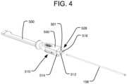
- FIG. 1illustrates an embodiment of an implant delivery system for insertion of an expandable implant 10 into an intervertebral space in accordance with the present invention.
- the expandable implant 10may, for example, be structured like any of the embodiments of expandable implants disclosed in the '199 Publication.
- a delivery tool 100 of the delivery systemis comprised of a handle 550 connected to an insertion shaft 500.
- the handle 550is adapted to be grasped by a surgeon or other user while the expandable implant 10 is inserted into the intervertebral space using the delivery tool 100, and the handle 550 includes features at its proximal end to facilitate engagement with, and control of, the expandable implant 10.
- the expandable implant 10is connectable to the distal end of the insertion shaft 500.
- connect caps of the delivery systemcan be fitted to the proximal end of the handle 550 via a connection mechanism that allows for connect caps to be interchanged.
- Each connect capserves a different purpose during implantation of the expandable implant 10 and can be readily switched without disconnecting the delivery tool 100 from the implant 10 and without removing the implant 10 from the intervertebral space.
- Connect cap 502allows for the advancement of plunger 506 for the fluid delivery system and plunger 508 for the bone graft supply line 404.
- Connect cap 504provides for a durable impaction surface during insertion of the expandable implant 10.
- Both connect cap 502 and connect cap 504have a button 503 that facilitates the attachment and removal of connect caps 502 and 504.
- the delivery tool 100also has a flip lever 510 that allows for unlocking and collapsing the expandable implant 10.
- FIGS. 2-5illustrate the insertion of rotatable threaded member 158.
- FIG. 2illustrates the delivery tool 100 having a receptacle 512 for receiving a rotatable threaded member 158, a receptacle 514 for the fluid delivery cannula 154, and a receptacle 516 for the bone graft supply line 404.
- the receptacle 512 for receiving the rotatable threaded member 158extends from the proximal end of the handle 500 through the distal end of the insertion shaft 500.
- the distal end of the rotatable threaded member 158is inserted into the proximal end of receptacle 512, as illustrated in FIG.
- the distal end of the rotatable threaded member 158extends out of the distal end of the insertion shaft 500 and connects with the proximal end of the expandable implant 10, as illustrated in FIG. 5 , in order to secure the implant 10 to the delivery tool 100.
- the expandable implant 10is secured to the delivery tool 100 by threading the threaded distal end of the rotatable threaded member 158 into a delivery tool anchor in the form of a threaded receptacle on the proximal end of the expandable implant 10, as disclosed in the '199 Publication.
- connect cap 502 or 504need not be attached to the handle 550 of the delivery tool 100.
- Receptacle 514is for receiving the fluid delivery cannula 154 of a fluid delivery system.
- the fluid delivery cannula 154allows for hydraulic fluid to be delivered to expandable implant 10 to expand expandable implant 10.
- the delivery tool 100may be easier to manipulate than some delivery tools, which may include bulky external syringes for supplying hydraulic fluid.
- fluid delivery cannula 154includes a reservoir 518 at the proximal end of the fluid delivery cannula 154 and an outlet 152 for delivering pressurized fluid at the distal end of the fluid delivery cannula 154.
- the reservoir 518has a rack mechanism 520 along its periphery that will interact with a pinion mechanism 522 at one end of flip lever 510, as shown in FIG. 15C (and discussed below).
- Outlet 152 for delivering pressurized fluidis inserted into receptacle 514 for the fluid delivery cannula at the proximal end of the handle 550, as illustrated in FIG. 7A .
- the outlet 152 for delivering pressurized fluidwill be located at the distal end of the insertion shaft 500, where it can fluidly communicate with the inlet of a pressure channel on the proximal end of the expandable implant 10.
- the outlet 152may project from the distal end of the insertion shaft 500, such that it is partially received within the inlet of the expandable implant, where it can form a sealing connection by engaging an o-ring positioned within the pressure channel of the implant 10, as disclosed in the '199 Publication.
- FIGS. 8-11Billustrate how connect cap 504 attaches to the proximal end of handle 550 of delivery tool 100. Preparation for attachment of connect cap 504 to handle 550 is illustrated in FIG. 8 .
- Connect cap 504provides for a flat surface on its proximal end to provide a durable impaction surface to help insert or place expandable implant 10.
- Connect cap 504can be interchanged with connect cap 502 and connect cap 702 at various points during the use of the delivery tool 100.
- Connect cap 502provides for plunger 506 and plunger 508 to be used in conjunction with the delivery tool 100.
- Connect cap 702provides a pistol-grip handle 700 that can be used to back-fill interior cavity 15 of expandable implant 10 with graft material.
- FIG. 9illustrates an attachment interface 528 at the proximal end of the handle 550 to which the connect cap 504 will be attached.
- the attachment interface 528includes two recesses 511 to allow for alignment between handle 550 and connect cap 504, by receiving corresponding projections 505 of the connect cap 504, as discussed below.
- the attachment interface 528also includes a locking mechanism 534 for keeping the connect cap 504 securely attached to the attachment interface 528.
- the locking mechanism 534includes a projection 501 having a recess 532 and one or more ( e.g ., two) overhead projections 530.
- the proximal end of the handle 550may also include a connection 536 (e.g ., a threaded bore) for securely and removably connecting to a slap hammer to assist with removal of the delivery tool 100 and implant 10 in the proximal direction if the implant 10 becomes stuck in the intervertebral space.
- a connection 536e.g ., a threaded bore
- connect cap 504is comprised of a sliding lock mechanism 535 having a central hole 537 in it that is shaped to receive the projection 501 on the proximal end of handle 550.
- the sliding lock mechanism 535is spring-biased, using springs 507.
- a stop pin 509is received through a slot 542 in the sliding lock mechanism 535 to constrain the travel of the sliding lock mechanism 535, such that the sliding lock mechanism 535 is retained within the connect cap 504.
- the sliding lock mechanism 535includes an outwardly projecting button 503, which may be a projecting portion of the sliding lock mechanism 535 projecting out of slot 539 on connect cap 504.
- the sliding lock mechanism 535allows for connect cap 504 to be locked to the locking mechanism 534 of the handle 550.
- button 503is pressed, causing springs 507 to compress, so that the central hole 537 becomes aligned with projection 501.
- Projections 505 on the distal end of connect cap 504align with recesses 511 on the proximal end of handle 550.
- the sliding lock mechanism 535slides such that stop pin 509 slides within slot 542, the end 540 of central opening 537 slides into the recess 532 of projection 501, and the side peripheral edges 544 of the sliding lock mechanism 535 slide under the overhead projections 530.
- the inter-engagement of all those structures discussed aboveprevents the connect cap 504 from becoming disconnected from handle 550 when the button 503 is in its undepressed position.
- Connect cap 504Removal of connect cap 504 is done through a similar process as attaching connect cap 504. That is, to remove connect cap 504, button 503 is pressed, causing springs 507 to compress. This shifts sliding lock mechanism 535 such that it is no longer locked into place by the overhead projections 530 on projection 501 or by the recess 532 in projection 501. Once button 503 is pressed, connect cap 504 can be lifted off handle 550.
- the connect cap 502may have substantially the same attachment structure as the connect cap 504, and therefore attaching and removing connect cap 502 may use the same process as connect cap 504, as described above.
- connect cap 502allows for either or both of plunger 506 or plunger 508 to be received through or removed from the connect cap 502 during the use of the delivery tool 100.
- Receptacle 524is threaded to receive the plunger 506 of the fluid delivery system, which is used to push the hydraulic fluid into the expandable implant 10.
- Receptacle 526receives plunger 508 that is used to push graft material in order to back-fill the expandable implant 10 after it has been expanded.
- FIG. 13illustrates how connect cap 502 can be attached to the proximal end of the handle 550 of the delivery tool 100 after having already received plunger 506.
- FIG. 14illustrates how connect cap 502 with plunger 506 align and function with all the other elements of handle 550.
- Plunger 506is seated within reservoir 518. Threadedly advancing the plunger 506 pushes the hydraulic fluid through fluid delivery cannula 154 and out the outlet 152, which is in fluid communication with the inlet of a pressure channel of the expandable implant 10.
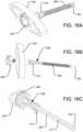
- FIGS. 16A-16Care exemplary of the shape of what the handle may look like.
- FIGS. 16A-16Cillustrate the handle 602 with a pressure gauge 600 embedded in the handle.
- Another embodiment of handle 602may be without such a recess or a pressure gauge embedded within it.
- Plunger 506can be operated by turning an attached handle. As the handle is turned, plunger 506 pushes hydraulic fluid from reservoir 518 through the fluid delivery cannula 154 and out the outlet 152 into the expandable implant 10 causing expandable implant 10 to expand.
- connect cap 502may be replaced with connect cap 1002, which includes a selector mechanism 1004 for selecting between two modes of travel by the plunger 1006 that pushes the hydraulic fluid into the implant 10.
- the plunger 1006may be threadedly engaged within a receptacle 1024 in the connect cap 1002 so that the plunger 1006 can travel ( i.e ., be advanced or retracted) by rotation about its longitudinal axis, similar to plunger 506.
- the threadsmay be disengaged from the plunger 1006 so that the plunger can travel by sliding it linearly through the receptacle 1024.
- the process of attaching and removing connect cap 1002is the same process as attaching and removing connect caps 502 and 504. That is, the connect cap 1002 may have a sliding lock mechanism 1035 constrained by a stop pin 1009 in the same manner as the sliding lock mechanism 535 and stop pin 509 of connect caps 502 and 504.
- the selector mechanism 1004 for selecting between the two modes of travelmay include a pivotable lever 1008 controllable by manipulating an external projection 1010 such that the lever 1008 pivots about a pivot pin 1012 received through a hole 1014 in the lever 1008.
- Such pivoting of the lever 1008may selectively bring threads 1016 on the lever 1008 into engagement with threads on the plunger 1006, as shown in FIG. 31D , or it may disengage the threads 1016 of the lever 1008 from the threads of the plunger 1006, as shown in FIG. 31E .
- the lever 1008can be held in the engaged and disengaged positions by a pin 1018 that engages respective notches 1020 and 1022 formed on the lever 1008.
- the lever 1008can be pivoted about the pivot pin 1012 to the disengaged position shown in FIG. 31E .
- the lever 1008can then be held in that disengaged position, in which the threads 1016 are spaced apart from the plunger 1006, by having the pin 1018 positioned in notch 1022.
- a biasing spring 1025may bias the lever 1008 back towards the engaged position.
- the lever 1008may be returned to the engaged position of FIG.
- the lever 1008may be moved back to the engaged position by simply pulling on the projection 1010 until the pin 1018 disengages the notch 1022.
- the two modes of travel discussed abovemay desirably permit the plunger 1006 to advance the hydraulic fluid into the implant in the rotational, threaded engagement mode, and then the plunger 1006 can be quickly released by disengaging the lever 1008 and pulling the plunger 1006 in the proximal direction.
- the two states of engagement between the lever 1008 and the plunger 1006may also give the surgeon a choice between two modes for delivery of the hydraulic fluid into the implant. That is, the surgeon may use the threaded advancement mode if a slower and more controlled advancement is appropriate, and/or if it is desirable to employ the mechanical advantage provided by the screw drive to amplify the input force. The surgeon may also choose to use the sliding, non-threaded mode if more rapid advancement of the plunger is desirable.
- the sliding, non-threaded modemay also desirably allow the plunger 1006 to be initially positioned into or removed from the receptacle 1024 of the connect cap 1002 relatively quickly, by eliminating the need to threadedly advance or retract the plunger 1006 the entire distance to the desired position.
- FIGS. 15A-15Dillustrate the interaction between rack mechanism 520 on reservoir 518 and pinion mechanism 522 on flip lever 510.
- outlet 152 for delivering pressurized fluid at the distal end of the fluid delivery cannula 154is a distance away from the pushable unlocking tether 212a in the expandable implant 10, as illustrated in FIGS. 15A-B .
- pressing distally on the pushable unlocking tether 212aallows for expandable implant 10 to collapse so that it can be repositioned if necessary.
- the expandable implant 10may include a pushable unlocking tether 212a engaged with a lower lock support so as to rotate the lower lock support 20 in the unlock direction when the pushable unlocking tether 212a is pushed in the distal direction.
- FIG. 15Cillustrates the activation of flip lever 510.
- the pinion mechanism 522 on the flip lever 510interacts with rack mechanism 520 on reservoir 518 to cause reservoir 518 and fluid delivery cannula 154 to move towards the distal end of insertion shaft 500.
- outlet 152 for delivering pressurized fluidalso moves distally and pushes on the internal unlocking mechanism within the expandable implant 10, as shown in FIG. 15D .
- the flip lever 510may beneficially allow for the relatively rigid structure of fluid delivery cannula 154 to move to activate the unlocking mechanism within expandable implant 10.
- FIGS. 16A-16Cexemplify handle 602 having a pressure gauge 600 to measure the pressure of the fluid in the fluid delivery cannula 154 as the handle 602 is turned.
- Pressure gauge 600provides numerical readings of the pressure of the fluid inside the expandable implant 10.
- Handle 602has a recess to receive pressure gauge 600.
- the distal end of pressure gauge 600has a threaded member that allows for a secure connection between pressure gauge 600 and handle 602.
- handle 602is threaded to receive the threaded proximal end of handle connector 610.
- a secure connection between handle 602 and handle connector 610is formed such that the rotation of handle 602 is transmitted to the handle connector 610.
- Handle connector 610connects handle 602 to plunger 606.
- the proximal end of plunger 606is fitted to have o-ring 608 as part of its assembly when connected to the distal end of handle connector 610.
- Plunger 606has a passageway 612 to provide fluid communication between the fluid delivery cannula 154 and the pressure gauge 600, so that the pressure gauge 600 can read the pressure in the fluid delivery cannula 154 as hydraulic fluid is delivered to the expandable implant 10.
- the passageway 612 in plunger 606communicates with passageways in handle 602 and handle connector 610, as shown in FIG. 16C .
- O-ring 608is in place to create a seal between the plunger 606 and handle connector 610 to minimize leakage between those components.
- Plunger 606also has an o-ring 604 located at the distal end of plunger 606 that creates a movable seal between the plunger 606 and the reservoir 518 of the fluid delivery cannula 154 as the plunger 606 advances within the reservoir 518.
- plunger 606The distal end of plunger 606 is inserted into the proximal end of receptacle 524 on connect cap 502.
- the threading of plunger 606is the same as plunger 506, allowing the threading of plunger 606 to also match the threading of receptacle.
- Plunger 606is operated by turning handle 602. As the handle 602 is turned, plunger 606 pushes hydraulic fluid from reservoir 518 through the fluid delivery cannula 154 and out the outlet 152 into the expandable implant 10, causing expandable implant 10 to expand.
- the pressure gauge 600may provide an absolute reading, instead of a relative measure, of the pressure of the fluid in the expandable implant 10. This may help prevent the surgeon from over-pressurizing the expandable implant 10.
- the gaugemay provide a relative pressure reading, such as by displaying color-coded regions associated with different pre-defined ranges of pressure.
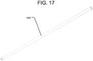
- the delivery systemprovides a bone graft supply system for back-filling the expandable implant 10 with graft material.
- the bone graft supply line 404 of the bone graft supply systemis a cannula that does not have to be inserted into the delivery tool 100 until after the expandable implant 10 is inserted.
- the cannula used for the bone graft supply line 404may also be translucent, which allows for better visualization of the amount of graft material being delivered.
- a large diameter bone graft supply line 404for receiving different sizes of graft material.
- the diameter of the bone graft supply line 404is 6mm ID.
- providing such a larger diameter bone graft supply line 404may beneficially allow for the use of more types of graft materials, such as cancellous chips, autograft, or synthetic bone graft materials such as those manufactured by Orthovita, Inc. under the trademark VITOSS ® .
- the distal end of the bone graft supply line 404is inserted into the proximal end of receptacle 516 on the handle 550.
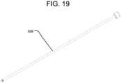
- a plunger 508 of the bone graft supply systemis introduced and inserted into the proximal end of the bone graft supply line 404, as illustrated in FIGS. 19-20B , for dispensing the graft material.
- plunger 508does not illustrate connect cap 502 being connected to handle 500, it may be in place when using plunger 508, in which case the plunger 508 can be introduced through the receptacle 526 of the connect cap when inserting the plunger 508 into the bone graft supply line 404.
- plunger 508is pushed in the distal direction, causing graft material to move distally through the bone graft supply line 404 and into the passage for graft material 392 of the expandable implant 10, to back-fill the interior cavity 15 of the expandable implant 10.
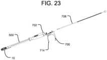
- connect cap 502may be replaced with connect cap 702, which is fitted with a pistol-grip handle 700 to form a bone graft gun for delivering graft material to the expandable implant 10.
- the process of attaching and removing connect cap 702is the same process as attaching and removing connect caps 502 and 504.
- plunger 708is inserted into the proximal end of the pistol-grip handle 700, as illustrated in FIG. 23 .
- Plunger 708is designed to work with the pistol-grip handle 700 using a ratcheting advancement mechanism. As the pistol-grip trigger 714 is squeezed towards the handle 700, the trigger 714 pivots about pivot point 706 such that movable pawl 710 connected to the trigger 714 engages ratchet teeth on the plunger 708 and pushes the plunger 708 distally. When the trigger 714 is released, a biasing spring 704 moves the trigger 714 back to its original position.
- the ratchet teethare pushed through a spring-biased fixed pawl 712 that prevents the plunger 708 from retracting in the proximal direction, unless the fixed pawl 712 is released from engagement with the plunger 708 by pushing the fixed pawl 712 against its spring 716.
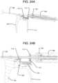
- the distal movement of the plunger 708pushes graft material through bone graft supply line 404 and into the passage for graft material 392 of the expandable implant 10 to fill the interior cavity 15 of the expandable implant 10. This process is exemplified in FIGS. 24A-24B . It is believed that using a ratcheting mechanism in this manner is preferable over tamping the bone graft material, as tamping may cause jamming of the bone graft material.
- FIG. 25illustrates one embodiment of a grafting block 800 that can be used to help pre-pack the implant 10 with graft material.
- a projection 804 from a base 802 of the grafting block 800is shaped to be at least partially received within the interior cavity 15 of the expandable implant 10, as shown in FIGS. 28A-28B , such that the projection 804 occupies a portion 808 of the interior cavity 15 extending from the passage 392, while leaving a remaining open region 810 of the interior cavity 15 unoccupied.
- the projection 804will prevent graft material packed into the open region 810 of the interior cavity 15 from filling the portion 808 extending from the passage 392, which might cause a blockage to the later-inserted graft material when back-filling the expandable implant 10 after insertion.
- the projection 804may be configured at one end to a height that matches the apex of the ramp 393 inside the expandable implant 10.
- the remainder of the projection 804may be configured to a height that is aligned with the boundary between the implant housing 11 and the expandable top end plate 13. In that way, any back-filled graft material added later will primarily fill the initial portion 808 that was blocked out, as well as the new volume created by the expansion of the implant.
- a retaining mechanism 806that will assist in keeping the expandable implant 10 on the grafting block 800.
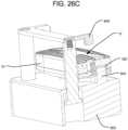
- the retaining mechanism 806is adjustable in height, as illustrated in FIGS. 26A-26C .
- Retaining mechanism 806allows for the expandable implant 10 to be placed on the projection 804 when the retaining mechanism 806 is in the raised position.
- the retaining mechanism 806assists in keeping the expandable implant 10 on the grafting block 800.
- FIGS. 27-28Bshow an alternative embodiment of the grafting block 800.
- the grafting block 800does not have the retaining mechanism 806.
- the use of the grafting block 800is optional. In one example, when no pre-packing of the graft material is performed (e.g., where the graft material is entirely supplied via the bone graft supply line 404 after the implant 10 has been implanted), the grafting block 800 may not be used.
- the ramp 393 inside the expandable implant 10is used to guide graft material into the area of the interior cavity 15 that was not pre-packed using the grafting block 800.
- the ramp 393guides new graft material into the expanded volume that is created once the expandable implant 10 is inserted and expanded.
- FIG. 29illustrates a flexible graft reamer 900 that can be used to clear blockages during backfilling. Graft reamer 900 can also be used to re-establish a grafting channel within passage 392.
- the graft reamer 900fits within delivery tool 100 while the insertion shaft 500 is connected to the expandable implant 10.
- the flexibility of graft reamer 900allows graft reamer 900 to fit within passage 392 in the expandable implant 10 and around ramp 393 in the expandable implant 10.
- FIGS. 32-44The components of another embodiment of a delivery system are illustrated in FIGS. 32-44 .
- the components of such embodimentare adapted to provide a surgeon with improved viewability of the expandable implant 10 (both directly and using fluoroscopy), as well as to improve the speed and efficiency of surgery, so as to minimize the time that tissue is retracted.
- modular partscan be attached to and detached from the insertion shaft of the delivery tool between each phase of the procedure.
- the modular instrumentsconsist of a handle 2550, an insertion shaft 2500, a rotatable threaded member 2158, a fluid delivery system 2400, a bone graft gun 2750, and a bone graft supply line 2404.
- the modular partscan be attached to the insertion shaft using a sliding lock mechanism 2535.
- the sliding lock mechanism 2535 of the handle 2550is illustrated in FIGS. 33A-C , but a similar sliding lock mechanism 2535 may be incorporated into the fluid delivery system 2400 and the bone graft gun 2750 for securely (yet removably) coupling those components with the insertion shaft 2500.
- the proximal end of the insertion shaft 2500may define a locking mechanism 2534 for securely coupling to the sliding lock mechanism 2535.
- the locking mechanism 2534is shaped to fit securely within a correspondingly shaped receptacle 2515 in the distal end of the handle 2550.
- the locking mechanism 2534includes a recess 2532 for engaging the sliding lock mechanism 2535, as discussed below.
- the sliding lock mechanism 2535operates similarly to the sliding lock mechanism 535 of the connect cap 504 illustrated in FIG. 11A .
- the sliding lock mechanism 2535may be slidable within the distal end of the handle 2550, and it may be biased by one or more springs 2507 so that a button 2503 of the sliding lock mechanism 2535 is biased to project outwardly from an exterior surface of the handle 2550.
- a stop pin 2509is received through a slot 2542 in the sliding lock mechanism 2535 to constrain the travel of the sliding lock mechanism 2535, such that the sliding lock mechanism 2535 is retained within the handle 2550.
- the sliding lock mechanism 2535includes a central hole 2537 that is shaped to receive the locking mechanism 2534 of the insertion shaft 2500.
- button 2503is pressed, causing the springs 2507 to compress, so that the central hole 2537 becomes aligned with the locking mechanism 2534.
- button 503is released, causing the springs 2507 to de-compress and lock the locking mechanism 2534 to the sliding lock mechanism 2535.
- the sliding lock mechanism 2535slides such that stop pin 2509 slides within the slot 2542, and the end 2540 of central opening 2537 slides into the recess 2532 of the locking mechanism 2534.
- the engagement of the sliding lock mechanism 2535 with the recess 2532prevents the handle 2550 from moving longitudinally and becoming disconnected from the insertion shaft 2500 when the button is in its undepressed position. Removal of the handle 2550 is then done through the reverse process, by pressing the button 2503 of the sliding lock mechanism 2535 and lifting the handle 2550 off of the insertion shaft 2500.
- FIG. 34Ashows an exploded view of the handle 2550, the insertion shaft 2500, the rotatable threaded member 2158, and the implant 10.
- the rotatable threaded member 2158includes a threaded portion on its distal end, which is inserted into the proximal end of a receptacle 2512 in the insertion shaft 2500.
- the rotatable threaded member 2158then extends out the distal end of the insertion shaft 2500 and screws into the implant 10 to attach the implant 10 to the insertion shaft 2500, a system which can remain intact throughout the procedure.
- the handle 2550then attaches to the proximal end of the insertion shaft 2500, e.g ., via sliding lock mechanism 2535, so that the handle 2550 can be grasped by the surgeon during insertion of the implant 10 into the intervertebral space.
- the proximal end of the handle 2550also desirably provides a durable impaction surface to help insert or place expandable implant 10.
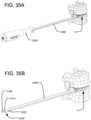
- the handle 2550includes a threaded bore 2536 on its proximal end for receiving a slap hammer, which can help with removal of the implant 10 if necessary. Placement of the implant 10 into the disc space is shown in FIG. 35A .
- the handle 2550can be removed from the insertion shaft 2500, as shown in FIG. 35B .
- the insertion shaft 2500is designed to have minimal cross-sectional dimensions, so as to increase visualization of the implant and its expansion, both directly by the surgeon as well as via fluoroscopy. The removal of the handle 2550 enhances visibility even further.
- the fluid delivery system 2400may be attached to the insertion shaft 2500 to expand the implant 10.
- An exploded view of the fluid delivery system 2400is illustrated in FIG. 36 .
- the fluid delivery system 2400includes a fluid delivery cannula 2154, a reservoir 2518, a plunger 2506, and a connect cap 2502.
- the connect cap 2502desirably includes a sliding lock mechanism 2535 for attaching the fluid delivery system 2400 to the locking mechanism 2534 at the proximal end of the insertion shaft 2500, in the same manner shown in FIGS. 33A-C . As shown in FIGS.
- the distal end of the fluid delivery cannula 2154may be inserted into a receptacle 2514 on the proximal end of the insertion shaft 2500.
- the outlet 2152 for delivering pressurized fluidwill be located at the distal end of the insertion shaft 2500, where it can fluidly communicate with the inlet of a pressure channel on the proximal end of the expandable implant 10. Specifically, in the same manner shown in FIGS.
- the outlet 2152 of this embodimentmay likewise project from the distal end of the insertion shaft 2500, such that it is partially received within the inlet of the expandable implant, where it can form a sealing connection by engaging an o-ring positioned within the pressure channel of the implant 10.
- the reservoir 2518may be angled with respect to the fluid delivery cannula 2154, which preferably positions the reservoir 2518 out of the line of site of the surgeon and/or the fluoroscope to the implant. Desirably, such positioning improves visibility for viewing the implant 10, as well as relocating a user's hands outside the radiation area of the fluoroscope.
- the reservoir 2518may be angled at 90 degrees with respect to the fluid delivery cannula 2154, although other angles to position the reservoir 2518 away from the viewing area could also be used.
- the reservoir 2518may receive the threaded plunger 2506 to pressurize the system.
- the plunger 2506may be engaged by a plunger engagement mechanism 2008, as shown in FIGS. 38A-C .
- the plunger engagement mechanism 2008 of the embodiment of FIGS. 38A-Cmay be designed to allow two modes of travel by the plunger 2506.
- the plunger engagement mechanism 2008is slidable within a proximal portion of the reservoir 2518, and it may be biased by one or more springs 2025 so that a button 2003 of plunger engagement mechanism 2008 is biased to project outwardly from an exterior surface of the reservoir 2518.
- a stop pin 2009is received through a slot 2042 in the plunger engagement mechanism 2008 to constrain the travel of the plunger engagement mechanism 2008, such that the plunger engagement mechanism 2008 is retained within the reservoir 2518.
- the plunger engagement mechanism 2008includes a central hole 2037 that is shaped to receive the plunger 2506 through it. At least one side of the hole includes a threaded portion 2016 structured to engage the threads of the plunger 2506.
- the button 2003holding the button 2003 in a depressed state allows for one of the two modes of travel by the plunger 2506, in which the threaded portion 2016 of the plunger engagement mechanism 2008 is disengaged from the threads of the plunger 2506, so that the plunger can travel along the reservoir 2518 by sliding the plunger 2506 linearly through the opening 2037 in the plunger engagement mechanism 2008.
- the spring 2025will de-compress and cause the threaded portion 2016 of the plunger engagement mechanism 2008 to move into engagement with the threads of the plunger 2506, which activates the other mode of travel by the plunger 2506. That is, due to the threaded engagement between the threads of the plunger 2506 and the threaded portion 2016 of the plunger engagement mechanism 2008, the plunger can travel along the reservoir 2518 by rotation about the longitudinal axis of the plunger.
- the two modes of travel of the plunger 2506 through the plunger engagement mechanism 2008may desirably permit the plunger 2506 to advance the hydraulic fluid into the implant in the rotational, threaded engagement mode, and then the plunger 2506 can be quickly released by depressing the button 2003 and pulling the plunger 2506 in the proximal direction.
- the two states of engagement between the plunger engagement mechanism 2008 and the plunger 2506may also give the surgeon a choice between two modes for delivery of the hydraulic fluid into the implant.
- the surgeonmay use the threaded advancement mode if a slower and more controlled advancement is appropriate, and/or if it is desirable to employ the mechanical advantage provided by the screw drive to amplify the input force.
- the surgeonmay also choose to use the sliding, non-threaded mode if more rapid advancement of the plunger is desirable.
- the sliding, non-threaded modemay also desirably allow the plunger 2506 to be initially positioned into or removed from the reservoir 2518 relatively quickly, by eliminating the need to threadedly advance or retract the plunger 2506 the entire distance to the desired position.
- the implant 10may be repositioned (if desired) by unlocking the expansion mechanism, such as by pressing distally on the unlocking tether 212a.
- the fluid delivery cannula 2154may be advanceable distally relative to the reservoir 2518, so as to push on the unlocking tether 212a within the expandable implant 10, in the same manner as illustrated in FIG. 15D .
- the fluid delivery system 2400may be removed from the insertion shaft 2500, and then a tube or other rigid, elongate component may be inserted into the same receptacle 2514 at the proximal end of the insertion shaft, so as to travel through the insertion shaft 2500 and push the unlocking tether 212a of the implant 10.
- the fluid delivery system 2400may be removed from the insertion shaft 2500, as shown in FIGS. 39A-B .
- the bone graft supply systemmay then be attached to the insertion shaft 2500 to fill the expanded implant 10 with bone graft material.
- the bone graft supply systemmay include a bone graft gun 2750 having a connect cap 2702 and a bone graft supply line 2404. The steps of using the bone graft gun 2750 are shown in FIGS. 40A-42C . Specifically, the bone graft supply line 2404 may first be connected to the bone graft gun 2750, as shown in FIGS. 40A-B .
- the proximal portion of the bone graft supply line 2404includes a recess 2519 around at least a portion of its outer periphery. That recess 2519 is shaped to engage the sliding lock mechanism 2535 of the connect cap 2702 of the bone graft gun 2750 in much the same manner that the recess 2532 on the insertion shaft 2500 engages the end 2540 of the central opening 2537 of the sliding lock mechanism 2535 in order to secure the insertion shaft 2500 to the handle 2550.
- both the bone graft supply line 2404 and the insertion shaft 2500can be secured to the connect cap 2702 of the bone graft gun 2750 via the sliding lock mechanism 2535.
- the proximal portion of the bone graft supply line 2404is inserted into a corresponding receptacle 2526 on the connect cap 2702 of the bone graft gun 2750 while the button 2503 of the sliding lock mechanism 2535 is depressed.
- the depressing of the button 2503causes the central opening 2537 of the sliding lock mechanism 2535 to be positioned such that the proximal portion of the bone graft supply line 2404 can be received through the central opening 2537.
- the bone graft supply line 2404can be secured to the bone graft gun 2740 by releasing the button 2503, which results in the biasing of the sliding lock mechanism 2535 to a shifted position, in which a portion of the periphery of the central opening 2537 is received within the recess 2519 of the bone graft supply line 2404, as shown in FIG. 41B .
- the bone graft gun 2750 with attached bone graft supply line 2404is then connected to the insertion shaft 2500, as shown in FIGS. 42A-B .
- the distal end of the bone graft supply line 2404is placed within an opening 2516 at the distal end of the insertion shaft 2500 (see FIGS. 34B and 39A ), such that the bone graft supply line 2404 is positioned alongside the insertion shaft 2500, where it may be partially received in and supported by a groove or channel 2517 extending along the insertion shaft 2500 (see FIG. 34B ).
- the connect cap 2702 of the bone graft supply gun 2750is also connected to the locking mechanism 2534 at the proximal end of the insertion shaft 2500 via a sliding lock mechanism 2535 like that of handle 2550.
- the distal end of plunger 2508is then inserted into the proximal end of the bone graft supply line 2404.
- Plunger 2508is designed to work with the bone graft gun 2750 using a pistol-grip trigger 2714 and a ratcheting advancement mechanism like that shown in FIGS. 24A-B .
- the insertion shaft 2500can be removed from the implant 10 by unthreading the rotatable threaded member 2158.
- the insertion shaftmay include bend angles within one or more planes.
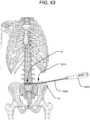
- an insertion shaft 3500may be provided having a single bend 3513 in a cephalad direction within the frontal or coronal plane. As shown in FIG. 43 , such bend 3515 may allow the insertion shaft 3500 to avoid the iliac crest IC.
- a bend in the anterior direction within the horizontal or transverse planemay additionally or alternatively be provided.
- an insertion shaft 4500may be provided having a compound bend 4513, consisting of a cephalad bend like that shown in FIG. 43 , as well as a bend in the anterior direction within the horizontal or transverse plane, as shown in FIG. 44 . All of such bends are preferably located approximately 40 millimeters from the distal end of the insertion shaft 3500, and the bends preferably have an angle between 15 and 30 degrees.
- One or more components of the delivery tool 100are desirably made of radiolucent material, such that they do not impair visualization of the implant 10 ( e.g ., by fluoroscopy) while it is being implanted and further manipulated.
- the components of the connect capsincluding the sliding lock mechanisms, may be fabricated from a plastic to reduce blockage of imaging, while the fluid delivery cannula 2154 and the reservoir 2518 may be fabricated from a metal for strength and durability.
- the rotatable threaded member 158may be made of a flexible material or it may have a flexible portion corresponding to the position of the bend.
- the fluid delivery cannula 154may also be fabricated from a flexible material, such as nitinol, to travel through the bent insertion shaft 3500.
- the bone graft supply line 404may also be fabricated from a flexible material, or a non-flexible material having a bend that matches that of the insertion shaft 3500.
Landscapes
- Health & Medical Sciences (AREA)
- Engineering & Computer Science (AREA)
- Biomedical Technology (AREA)
- Orthopedic Medicine & Surgery (AREA)
- Transplantation (AREA)
- Heart & Thoracic Surgery (AREA)
- Oral & Maxillofacial Surgery (AREA)
- Cardiology (AREA)
- Vascular Medicine (AREA)
- Life Sciences & Earth Sciences (AREA)
- Animal Behavior & Ethology (AREA)
- General Health & Medical Sciences (AREA)
- Public Health (AREA)
- Veterinary Medicine (AREA)
- Neurology (AREA)
- Physical Education & Sports Medicine (AREA)
- Prostheses (AREA)
Description
- Intervertebral implants are commonly used in spinal surgery, such as in interbody fusion procedures, in which an implant (e.g., a spacer or cage) is placed in the disc space between two vertebrae to be fused together. At least a portion of the disc is typically removed before the implant is positioned in the intervertebral space, and the implant may be supplemented with bone graft material to promote fusion of the vertebrae. Interbody fusion procedures may also be performed in conjunction with other types of fixation, such as pedicle screw fixation, to provide additional stability, particularly while the vertebrae fuse together.
- Different interbody fusion procedures can be distinguished by their location along the spine (e.g., in the cervical, thoracic, or lumbar regions); by the type of implant used; and by the surgical approach to the intervertebral space, in which different surgical approaches often imply different structural characteristics of the implant or implants used. Different surgical approaches to the spine include anterior, posterior, and lateral. Examples of interbody fusion techniques performed along a posterior approach include posterior lumbar interbody fusion (PLIF) and transforaminal lumbar interbody fusion (TLIF). PLIF techniques typically include positioning two intervertebral implants into the intervertebral space along a posterior to anterior direction, with one implant being positioned towards the left side of the spine and one implant being positioned towards the right side of the spine. The implants used in such PLIF techniques typically have a straight shape, in that they extend along a central axis. TLIF techniques, by contrast, typically include positioning one intervertebral implant into the intervertebral space (often towards the anterior portion of the intervertebral space) from the posterior of the patient, but the spine is approached on one side from a more lateral position than in PLIF techniques. The implants used in such TLIF techniques are often curved, such that they have an overall kidney bean-like shape. Interbody fusion techniques performed along a lateral approach, on the other hand, often involve implants that are generally symmetric along their linear longitudinal axis (e.g., having a substantially rectangular or oval shape), but the implants are typically larger than those used in PLIF or TLIF techniques. That is, intervertebral implants used in lateral approaches often cover a substantial portion of the disc space.
- Included among the different types of intervertebral implants are expandable implants. Such implants often have an initially contracted configuration, such that they have a low profile in the superior-inferior direction, in order to ease insertion into the intervertebral space. Such expandable implants can then be expanded in the superior-inferior direction after implantation, so as to securely engage and stabilize the vertebrae on both sides of the intervertebral space. Examples of such expandable intervertebral implants are disclosed in
U.S. Patent Application Publication No. 2017/0333199 (hereinafter "the '199 Publication"),U.S. Patent No. 8,992,620 (hereinafter "the '620 Patent"), and inU.S. Patent Application Publication No. 2017/0290671 (hereinafter "the '671 Publication"). Expandable intervertebral implants having certain similar features to those in the `620 Patent, the '199 Publication, and the '671 Publication are disclosed herein, and therefore some similar nomenclature is used herein for clarity and consistency. - Various tools that interface with the expandable implants for insertion and expansion are used. Although considerable effort has been devoted in the art to optimization of such tools, still further improvement would be desirable. Document
US 2014/303730 relates to a tool system to remove tissue from the intervertebral space, a system for delivery of inflatable membranes or balloons into the intervertebral space and a fluid management system to provide for controlled delivery of fluids into the balloons.US2009248163 discloses a delivery system for implantation of an implant into an intervertebral space that features the use of an extension or other accessory. - The present invention is as defined in claim 1 and provides a delivery system for implantation of an implant into an intervertebral space. A delivery system in accordance with the invention includes an elongated tool having a distal end removably securable to the implant. A proximal end of the elongated tool has an attachment interface for detachable securement to a plurality of different modules. Each module may be adapted to effectuate a different function of the delivery system during implantation of the implant.
- The different functions of the modules may include: grasping the elongated tool, providing an impaction surface for driving the advancement of the implant, advancing a graft material through the elongated tool into the implant, and actuating the expansion of the implant. For example, one of the modules may be a handle. At least one of the modules may define a flat impaction surface at a proximal end of a handle for driving the advancement of the elongated tool. That flat impaction surface may be defined on a connect cap removably attachable to the handle. Another one of the modules may be a bone graft supply system. The bone graft supply system may include a plunger advanceable in a distal direction to drive graft material distally through the elongated tool and into the implant. The distal advancement of the plunger may be driven by squeezing a trigger of a pistol-grip handle. Another one of the modules may be an expander for actuating the expansion of the implant. The expander may include a fluid delivery system for supplying hydraulic fluid into the implant to expand the implant. The fluid delivery system may include a pressure gauge for displaying the pressure of the hydraulic fluid supplied to the implant. The fluid delivery system may include a plunger advanceable within a fluid reservoir for driving the hydraulic fluid into the implant via a fluid delivery cannula. The fluid reservoir may be oriented transverse to the fluid delivery cannula, such that the plunger is advanceable within the reservoir along a direction transverse to the fluid delivery cannula. The fluid delivery system may include a selector mechanism for switching between two different modes of travel by the plunger. One of the two modes of travel by the plunger may include rotation of the plunger about its longitudinal axis, such that the plunger travels along a threaded connection. Another one of the two modes of travel by the plunger may include sliding the plunger linearly along the longitudinal axis of the plunger. The different modules may be securable to and detachable from the proximal end of the elongated tool by depressing a button on the respective module.
- Other aspects of the invention provide a fluid delivery system for removable connection to a hydraulically expandable intervertebral implant. A fluid delivery system in accordance with such aspects of the invention may include a fluid delivery cannula and a plunger having a handle adapted to be grasped by a surgeon or other user. The handle may include a gauge configured to display an indication correlated to the hydraulic pressure supplied to the intervertebral implant via the fluid delivery cannula.
- Yet other aspects of the invention provide a tool removably securable to an expandable intervertebral implant. A tool in accordance with such aspects of the invention is configured for supplying a hydraulic fluid into the implant to expand the implant. The tool preferably includes an elongated shaft having a fluid delivery cannula therein. The fluid delivery cannula may have a distal end engageable with the implant such that the distal end is in fluid communication with a port on the implant. At least the distal end of the fluid delivery cannula is desirably a relatively rigid structure. The tool is preferably adapted to induce movement of the fluid delivery cannula in a distal direction relative to the shaft, such that the distal end of the fluid delivery cannula moves into engagement with a lock release within the implant so as to unlock the expansion of the implant and permit the implant to collapse. In accordance with some aspects of the invention, the movement of the fluid delivery cannula in the distal direction relative to the shaft may be induced by a pivotable lever connected to the tool.
- Other aspects of the invention provide an expandable intervertebral implant. An implant in accordance with such aspects of the invention preferably include a housing and a top plate movable away from the housing so as to expand the implant. The housing may include a side surface extending transverse to the top plate along a height dimension of the implant. The side surface may have an opening therein, which opening may communicate with an interior cavity of the implant so as to permit a graft material to be supplied into the interior cavity via the opening. The housing may also include a ramp extending between the opening and the interior cavity. The ramp is preferably oriented at an oblique angle to the side surface of the housing, so as to direct the graft material to a particular location of the interior cavity along the height dimension of the implant. A spinal implant system in accordance with yet further aspects of the invention may include such an expandable intervertebral implant and may further include a reamer having a flexible shaft. The shaft of such reamer is preferably adapted to be received through the opening in the side surface of the implant and along the ramp into the interior cavity of the implant. Desirably, such reamer may be used to clear graft blockages during backfilling of the implant.
- Still other aspects of the invention provide a block for supporting an intervertebral implant while packing an interior cavity of the implant with graft material. A block in accordance with such aspects of the invention may include a base and a projection extending from the base. The projection is desirably sized to be received through a first opening in the implant such that the projection is positioned at least partially within the interior cavity of the implant. A spinal implant system in accordance with yet further aspects of the invention may include such a block and may further include an intervertebral implant. Such implant desirably includes a second opening on an opposite side of the implant from the first opening. When the implant is supported on the block with the projection received through the first opening in the implant, the second opening is preferably oriented upwardly so as to receive a supply of graft material into the interior cavity through the second opening. The projection of the block is desirably configured to closely fit within the interior cavity of the implant, such that graft material positioned within the interior cavity is prevented from flowing downwardly past an upper surface of the projection into a portion of the interior cavity occupied by the projection. In accordance with some aspects of the invention, the block may include a retaining mechanism configured to move into engagement with the implant to secure the implant to the block.
FIG. 1 is a perspective view of an implant delivery system in accordance with one embodiment of the present invention connected to an expandable implant.FIG. 2 is a perspective view of a delivery tool of the implant delivery system ofFIG. 1 .FIG. 3 is a perspective view of a rotatable threaded member.FIG. 4 is a perspective view of the insertion of the rotatable threaded member into the delivery tool.FIG. 5 is a perspective view of the rotatable threaded member inserted into the delivery tool connected to an expandable implant.FIG. 6 is a perspective view of a fluid delivery cannula.FIG. 7A is a perspective view of the insertion of the fluid delivery cannula into the delivery tool.FIG. 7B is a perspective view of the distal end of the delivery tool with the fluid delivery cannula inserted and projecting distally towards the expandable implant.FIG. 8 is a perspective view of the attachment of a connect cap for impaction to the handle of the delivery tool.FIG. 9 is a perspective view of the proximal end of the handle of the delivery tool.FIG. 10 is an exploded view of the connect cap ofFIG. 8 .FIG. 11A is a perspective, cross-sectional view showing a sliding lock mechanism within the connect cap ofFIG. 8 .FIG. 11B is a perspective view of the connect cap ofFIG. 8 connected to the proximal end of the handle of the delivery tool.FIG. 12 is a perspective view of a different connect cap with a plunger for the fluid delivery cannula.FIG. 13 is a perspective view of the attachment of the connect cap and plunger ofFIG. 12 to the handle of the delivery tool.FIG. 14 is a perspective, cross-sectional view of the connect cap and plunger ofFIG. 12 attached to the proximal end of the handle of the delivery tool.FIGS. 15A ,15C and15D are top, cross-sectional views of the delivery tool connected to the expandable implant, showing the movement of the fluid delivery cannula by a flip lever of the delivery tool.FIG. 15B is a perspective, cross-sectional view of the expandable implant connected to the distal end of the delivery tool.FIG. 16A is a perspective view of an alternative embodiment of a plunger containing a pressure gauge for the fluid delivery cannula.FIG. 16B is an exploded view of the plunger ofFIG. 16A .FIG. 16C is a cross-sectional view of the plunger ofFIG. 16A .FIG. 17 is a perspective view of a bone graft supply line.FIG. 18 is a perspective view of the insertion of the bone graft supply line into the delivery tool.FIG. 19 is a perspective view of a plunger for the bone graft supply line.FIGS. 20A-20B are perspective views of the insertion of the plunger into the bone graft supply line.FIGS. 21A-21B are cross-sectional views of the movement of the plunger ofFIG. 19 within the bone graft supply line.FIGS. 22A-22B are perspective views of the attachment of a connect cap fitted with a pistol-grip handle.FIG. 23 is a perspective view of the insertion of a plunger that fits within the pistol-grip handle.FIGS. 24A-24B are side, cross-sectional views of the pistol-grip handle with the plunger inserted to deliver graft material to the expandable implant.FIG. 25 is a perspective view of a grafting block.FIGS. 26A-26B are perspective views of the grafting block with the expandable implant placed upon it and a retaining mechanism at varying heights.FIG. 26C is a perspective, cross sectional view of the grafting block with retaining mechanism having the expandable implant placed upon it.FIG. 27 is a perspective view of the expandable implant on an alternative embodiment of a grafting block without a retaining mechanism.FIGS. 28A-28B are perspective, cross-sectional views of the expandable implant on the grafting block ofFIG. 27 .FIG. 29 is a perspective view of a graft reamer.FIGS. 30A-30B are side, cross sectional views of the graft reamer inserted into the expandable implant.FIG. 31A is a perspective view of the attachment to the handle of the delivery tool of a connect cap with a fluid delivery plunger having two modes of travel.FIG. 31B is an exploded view of the connect cap ofFIG. 31A .FIG. 31C is a perspective view of a lever of a selector mechanism of the connect cap ofFIG. 31A .FIG. 31D is a cross-sectional view of the selector mechanism of the connect cap ofFIG. 31A in an engaged position.FIG. 31E is a cross-sectional view of the selector mechanism of the connect cap ofFIG. 31A in a disengaged position.FIG. 32 is an exploded view of an implant delivery system in accordance with another embodiment of the present invention.FIG. 33A is a perspective view of the attachment of a handle of the implant delivery system ofFIG. 32 to an insertion shaft of the implant delivery system.FIG. 33B is a cross-sectional view of the arrangement ofFIG. 33A .FIG. 33C is an enlarged, cross-sectional view of the handle and insertion shaft ofFIGS. 33A-B connected to one another.FIG. 34A is an exploded view of a delivery tool of the implant delivery system ofFIG. 32 .FIG. 34B is a perspective view of the delivery tool ofFIG. 34A connected to an expandable implant.FIG. 35A is a perspective view of the delivery tool inserting and placing the implant into the intervertebral space.FIG. 35B is a perspective view of the arrangement ofFIG. 35A , with the handle removed from the insertion shaft of the delivery tool.FIG. 36 is an exploded view of a fluid delivery system of the implant delivery system ofFIG. 32 .FIGS. 37A-37B are perspective views of the insertion of the fluid delivery system ofFIG. 36 into the delivery tool.FIG. 38A-38B are cross-sectional views of the insertion of a plunger of the fluid delivery system ofFIG. 36 into a reservoir of the fluid delivery system.FIG. 38C is a perspective, cross-sectional view of a plunger engagement mechanism engaging the plunger of the fluid delivery system ofFIG. 36 .FIGS. 39A-39B are perspective views of the insertion shaft of the implant delivery system ofFIG. 32 connected to the expanded implant within the intervertebral space.FIGS. 40A-40B are perspective views of the insertion of a bone graft supply line into a bone graft supply system of the implant delivery system ofFIG. 32 .FIGS. 41A-41B are perspective, cross-sectional views of the bone graft supply line connected to the bone graft supply system ofFIGS. 40A-B .FIGS. 42A-42B are perspective views of the insertion of a bone graft supply system into the implant delivery system ofFIG. 32 .FIG. 42C is a perspective view of the bone graft supply system ofFIGS. 42A-B injecting bone graft material into the implant.FIG. 43 is a simplified view showing a delivery tool in accordance with another embodiment of the present invention inserting an implant into an intervertebral space along a lateral approach.FIG. 44 is a perspective view of a delivery tool in accordance with another embodiment of the present invention.FIG. 1 illustrates an embodiment of an implant delivery system for insertion of anexpandable implant 10 into an intervertebral space in accordance with the present invention. Theexpandable implant 10 may, for example, be structured like any of the embodiments of expandable implants disclosed in the '199 Publication. Adelivery tool 100 of the delivery system is comprised of ahandle 550 connected to aninsertion shaft 500. Thehandle 550 is adapted to be grasped by a surgeon or other user while theexpandable implant 10 is inserted into the intervertebral space using thedelivery tool 100, and thehandle 550 includes features at its proximal end to facilitate engagement with, and control of, theexpandable implant 10. Theexpandable implant 10 is connectable to the distal end of theinsertion shaft 500. Various connect caps of the delivery system can be fitted to the proximal end of thehandle 550 via a connection mechanism that allows for connect caps to be interchanged. Each connect cap serves a different purpose during implantation of theexpandable implant 10 and can be readily switched without disconnecting thedelivery tool 100 from theimplant 10 and without removing theimplant 10 from the intervertebral space.Connect cap 502 allows for the advancement ofplunger 506 for the fluid delivery system andplunger 508 for the bonegraft supply line 404.Connect cap 504 provides for a durable impaction surface during insertion of theexpandable implant 10. Both connectcap 502 and connectcap 504 have abutton 503 that facilitates the attachment and removal of connect caps 502 and 504. Thedelivery tool 100 also has aflip lever 510 that allows for unlocking and collapsing theexpandable implant 10.FIGS. 2-5 illustrate the insertion of rotatable threadedmember 158.FIG. 2 illustrates thedelivery tool 100 having areceptacle 512 for receiving a rotatable threadedmember 158, areceptacle 514 for thefluid delivery cannula 154, and areceptacle 516 for the bonegraft supply line 404. Thereceptacle 512 for receiving the rotatable threadedmember 158 extends from the proximal end of thehandle 500 through the distal end of theinsertion shaft 500. The distal end of the rotatable threadedmember 158, as illustrated inFIG. 3 , is inserted into the proximal end ofreceptacle 512, as illustrated inFIG. 4 . The distal end of the rotatable threadedmember 158 extends out of the distal end of theinsertion shaft 500 and connects with the proximal end of theexpandable implant 10, as illustrated inFIG. 5 , in order to secure theimplant 10 to thedelivery tool 100. Specifically, theexpandable implant 10 is secured to thedelivery tool 100 by threading the threaded distal end of the rotatable threadedmember 158 into a delivery tool anchor in the form of a threaded receptacle on the proximal end of theexpandable implant 10, as disclosed in the '199 Publication. When connecting the rotatable threadedmember 158 to theexpandable implant 10, connectcap handle 550 of thedelivery tool 100.Receptacle 514 is for receiving thefluid delivery cannula 154 of a fluid delivery system. Thefluid delivery cannula 154 allows for hydraulic fluid to be delivered toexpandable implant 10 to expandexpandable implant 10. Beneficially, by receiving the hydraulic fluid delivery components within thehandle 550 and insertion shaft 500 (e.g., in receptacle 514), thedelivery tool 100 may be easier to manipulate than some delivery tools, which may include bulky external syringes for supplying hydraulic fluid.- As illustrated in
FIG. 6 ,fluid delivery cannula 154 includes areservoir 518 at the proximal end of thefluid delivery cannula 154 and anoutlet 152 for delivering pressurized fluid at the distal end of thefluid delivery cannula 154. Thereservoir 518 has arack mechanism 520 along its periphery that will interact with apinion mechanism 522 at one end offlip lever 510, as shown inFIG. 15C (and discussed below).Outlet 152 for delivering pressurized fluid is inserted intoreceptacle 514 for the fluid delivery cannula at the proximal end of thehandle 550, as illustrated inFIG. 7A . After thefluid delivery cannula 154 is seated in thehandle 550 andinsertion shaft 500, theoutlet 152 for delivering pressurized fluid will be located at the distal end of theinsertion shaft 500, where it can fluidly communicate with the inlet of a pressure channel on the proximal end of theexpandable implant 10. As shown inFIGS. 15A and7B , theoutlet 152 may project from the distal end of theinsertion shaft 500, such that it is partially received within the inlet of the expandable implant, where it can form a sealing connection by engaging an o-ring positioned within the pressure channel of theimplant 10, as disclosed in the '199 Publication. FIGS. 8-11B illustrate howconnect cap 504 attaches to the proximal end ofhandle 550 ofdelivery tool 100. Preparation for attachment ofconnect cap 504 to handle 550 is illustrated inFIG. 8 .Connect cap 504 provides for a flat surface on its proximal end to provide a durable impaction surface to help insert or placeexpandable implant 10.Connect cap 504 can be interchanged withconnect cap 502 and connectcap 702 at various points during the use of thedelivery tool 100.Connect cap 502 provides forplunger 506 andplunger 508 to be used in conjunction with thedelivery tool 100.Connect cap 702 provides a pistol-grip handle 700 that can be used to back-fill interior cavity 15 ofexpandable implant 10 with graft material.FIG. 9 illustrates anattachment interface 528 at the proximal end of thehandle 550 to which theconnect cap 504 will be attached. Theattachment interface 528 includes tworecesses 511 to allow for alignment betweenhandle 550 and connectcap 504, by receiving correspondingprojections 505 of theconnect cap 504, as discussed below. Theattachment interface 528 also includes alocking mechanism 534 for keeping theconnect cap 504 securely attached to theattachment interface 528. Thelocking mechanism 534 includes aprojection 501 having arecess 532 and one or more (e.g., two)overhead projections 530. Although not illustrated in the other figures, the proximal end of thehandle 550 may also include a connection 536 (e.g., a threaded bore) for securely and removably connecting to a slap hammer to assist with removal of thedelivery tool 100 andimplant 10 in the proximal direction if theimplant 10 becomes stuck in the intervertebral space.- As illustrated in
FIG. 10 , connectcap 504 is comprised of a slidinglock mechanism 535 having acentral hole 537 in it that is shaped to receive theprojection 501 on the proximal end ofhandle 550. The slidinglock mechanism 535 is spring-biased, using springs 507. Astop pin 509 is received through aslot 542 in the slidinglock mechanism 535 to constrain the travel of the slidinglock mechanism 535, such that the slidinglock mechanism 535 is retained within theconnect cap 504. The slidinglock mechanism 535 includes an outwardly projectingbutton 503, which may be a projecting portion of the slidinglock mechanism 535 projecting out ofslot 539 onconnect cap 504. - The sliding
lock mechanism 535 allows forconnect cap 504 to be locked to thelocking mechanism 534 of thehandle 550. Specifically, whenconnect cap 504 is being attached to the proximal end ofhandle 550, as illustrated inFIGS. 11A-11B ,button 503 is pressed, causingsprings 507 to compress, so that thecentral hole 537 becomes aligned withprojection 501.Projections 505 on the distal end ofconnect cap 504 align withrecesses 511 on the proximal end ofhandle 550. Once connectcap 504 is aligned and seated on theattachment interface 528 at the proximal end ofhandle 550,button 503 is released, causingsprings 507 to de-compress and lock thelocking mechanism 534 into place. Specifically, when thebutton 503 is released, the slidinglock mechanism 535 slides such thatstop pin 509 slides withinslot 542, theend 540 ofcentral opening 537 slides into therecess 532 ofprojection 501, and the sideperipheral edges 544 of the slidinglock mechanism 535 slide under theoverhead projections 530. The inter-engagement of all those structures discussed above prevents theconnect cap 504 from becoming disconnected fromhandle 550 when thebutton 503 is in its undepressed position. - Removal of
connect cap 504 is done through a similar process as attachingconnect cap 504. That is, to removeconnect cap 504,button 503 is pressed, causingsprings 507 to compress. This shifts slidinglock mechanism 535 such that it is no longer locked into place by theoverhead projections 530 onprojection 501 or by therecess 532 inprojection 501. Oncebutton 503 is pressed, connectcap 504 can be lifted offhandle 550. - The
connect cap 502 may have substantially the same attachment structure as theconnect cap 504, and therefore attaching and removingconnect cap 502 may use the same process as connectcap 504, as described above. - The structure of
connect cap 502 allows for either or both ofplunger 506 orplunger 508 to be received through or removed from theconnect cap 502 during the use of thedelivery tool 100. There are multiple receptacles in theconnect cap 502.Receptacle 524 is threaded to receive theplunger 506 of the fluid delivery system, which is used to push the hydraulic fluid into theexpandable implant 10.Receptacle 526 receivesplunger 508 that is used to push graft material in order to back-fill theexpandable implant 10 after it has been expanded. - The distal end of
plunger 506 is inserted intoreceptacle 524 onconnect cap 502, as seen inFIG 12 .Receptacle 524 is threaded to match the threading ofplunger 506.FIG. 13 illustrates howconnect cap 502 can be attached to the proximal end of thehandle 550 of thedelivery tool 100 after having already receivedplunger 506. FIG. 14 illustrates howconnect cap 502 withplunger 506 align and function with all the other elements ofhandle 550.Plunger 506 is seated withinreservoir 518. Threadedly advancing theplunger 506 pushes the hydraulic fluid throughfluid delivery cannula 154 and out theoutlet 152, which is in fluid communication with the inlet of a pressure channel of theexpandable implant 10.Plunger 506 for thefluid delivery cannula 154 has a structure on the proximal end that allows for a variety of handles to be attached for turningplunger 506.FIGS. 16A-16C are exemplary of the shape of what the handle may look like.FIGS. 16A-16C illustrate thehandle 602 with apressure gauge 600 embedded in the handle. Another embodiment ofhandle 602 may be without such a recess or a pressure gauge embedded within it.Plunger 506 can be operated by turning an attached handle. As the handle is turned,plunger 506 pushes hydraulic fluid fromreservoir 518 through thefluid delivery cannula 154 and out theoutlet 152 into theexpandable implant 10 causingexpandable implant 10 to expand.- In an alternative embodiment, as illustrated in
FIGS. 31A-31E , connectcap 502 may be replaced withconnect cap 1002, which includes aselector mechanism 1004 for selecting between two modes of travel by theplunger 1006 that pushes the hydraulic fluid into theimplant 10. In one mode, theplunger 1006 may be threadedly engaged within areceptacle 1024 in theconnect cap 1002 so that theplunger 1006 can travel (i.e., be advanced or retracted) by rotation about its longitudinal axis, similar toplunger 506. In another mode, the threads may be disengaged from theplunger 1006 so that the plunger can travel by sliding it linearly through thereceptacle 1024. The process of attaching and removingconnect cap 1002 is the same process as attaching and removing connectcaps connect cap 1002 may have a slidinglock mechanism 1035 constrained by astop pin 1009 in the same manner as the slidinglock mechanism 535 and stoppin 509 of connect caps 502 and 504. - The
selector mechanism 1004 for selecting between the two modes of travel may include apivotable lever 1008 controllable by manipulating anexternal projection 1010 such that thelever 1008 pivots about apivot pin 1012 received through ahole 1014 in thelever 1008. Such pivoting of thelever 1008 may selectively bringthreads 1016 on thelever 1008 into engagement with threads on theplunger 1006, as shown inFIG. 31D , or it may disengage thethreads 1016 of thelever 1008 from the threads of theplunger 1006, as shown inFIG. 31E . Thelever 1008 can be held in the engaged and disengaged positions by apin 1018 that engagesrespective notches lever 1008. Thus, by pressing on theprojection 1010 when thelever 1008 is in the engaged position shown inFIG. 31D (in which thepin 1018 is received by notch 1020), thelever 1008 can be pivoted about thepivot pin 1012 to the disengaged position shown inFIG. 31E . Thelever 1008 can then be held in that disengaged position, in which thethreads 1016 are spaced apart from theplunger 1006, by having thepin 1018 positioned innotch 1022. Abiasing spring 1025 may bias thelever 1008 back towards the engaged position. Thus, thelever 1008 may be returned to the engaged position ofFIG. 31D by pushing distally on abutton 1026 connected to thepin 1018, so that thepin 1018 compresses aspring 1028 until a narrowedregion 1030 of thepin 1018 becomes aligned with thenotch 1022, thus allowing thelever 1008 to rotate back towards the engaged position under the influence of thebiasing spring 1025. Alternatively, thelever 1008 may be moved back to the engaged position by simply pulling on theprojection 1010 until thepin 1018 disengages thenotch 1022. - The two modes of travel discussed above may desirably permit the
plunger 1006 to advance the hydraulic fluid into the implant in the rotational, threaded engagement mode, and then theplunger 1006 can be quickly released by disengaging thelever 1008 and pulling theplunger 1006 in the proximal direction. The two states of engagement between thelever 1008 and theplunger 1006 may also give the surgeon a choice between two modes for delivery of the hydraulic fluid into the implant. That is, the surgeon may use the threaded advancement mode if a slower and more controlled advancement is appropriate, and/or if it is desirable to employ the mechanical advantage provided by the screw drive to amplify the input force. The surgeon may also choose to use the sliding, non-threaded mode if more rapid advancement of the plunger is desirable. The sliding, non-threaded mode may also desirably allow theplunger 1006 to be initially positioned into or removed from thereceptacle 1024 of theconnect cap 1002 relatively quickly, by eliminating the need to threadedly advance or retract theplunger 1006 the entire distance to the desired position. FIGS. 15A-15D illustrate the interaction betweenrack mechanism 520 onreservoir 518 andpinion mechanism 522 onflip lever 510. Beforeflip lever 510 is activated,outlet 152 for delivering pressurized fluid at the distal end of thefluid delivery cannula 154 is a distance away from thepushable unlocking tether 212a in theexpandable implant 10, as illustrated inFIGS. 15A-B . As disclosed in the '199 Publication, pressing distally on thepushable unlocking tether 212a allows forexpandable implant 10 to collapse so that it can be repositioned if necessary. That is, theexpandable implant 10 may include apushable unlocking tether 212a engaged with a lower lock support so as to rotate thelower lock support 20 in the unlock direction when thepushable unlocking tether 212a is pushed in the distal direction.FIG. 15C illustrates the activation offlip lever 510. As theflip lever 510 is pivoted outwardly from its initial position extending along and substantially flush with the outer surface of thehandle 550 as shown inFIGS. 13-14 , thepinion mechanism 522 on theflip lever 510 interacts withrack mechanism 520 onreservoir 518 to causereservoir 518 andfluid delivery cannula 154 to move towards the distal end ofinsertion shaft 500. Asreservoir 518 andfluid delivery cannula 154 move towards the distal end ofinsertion shaft 500,outlet 152 for delivering pressurized fluid also moves distally and pushes on the internal unlocking mechanism within theexpandable implant 10, as shown inFIG. 15D . This causes theexpandable implant 10 to collapse so that theexpandable implant 10 can be repositioned if necessary. Returningflip lever 510 to the original position withdrawsoutlet 152,fluid delivery cannula 154, andreservoir 518 back to the original depth, allowingexpandable implant 10 to be re-expanded.- Instead of using a thin, flexible wire to push the unlocking mechanism within the
expandable implant 10, as may be done in some other delivery tools, theflip lever 510 may beneficially allow for the relatively rigid structure offluid delivery cannula 154 to move to activate the unlocking mechanism withinexpandable implant 10. - In another embodiment of
delivery tool 100,FIGS. 16A-16C exemplify handle 602 having apressure gauge 600 to measure the pressure of the fluid in thefluid delivery cannula 154 as thehandle 602 is turned.Pressure gauge 600 provides numerical readings of the pressure of the fluid inside theexpandable implant 10. Handle 602 has a recess to receivepressure gauge 600. The distal end ofpressure gauge 600 has a threaded member that allows for a secure connection betweenpressure gauge 600 and handle 602. - The distal end of
handle 602 is threaded to receive the threaded proximal end ofhandle connector 610. A secure connection betweenhandle 602 and handleconnector 610 is formed such that the rotation ofhandle 602 is transmitted to thehandle connector 610.Handle connector 610 connects handle 602 toplunger 606. The proximal end ofplunger 606 is fitted to have o-ring 608 as part of its assembly when connected to the distal end ofhandle connector 610. Plunger 606 has apassageway 612 to provide fluid communication between thefluid delivery cannula 154 and thepressure gauge 600, so that thepressure gauge 600 can read the pressure in thefluid delivery cannula 154 as hydraulic fluid is delivered to theexpandable implant 10. Thepassageway 612 inplunger 606 communicates with passageways inhandle 602 and handleconnector 610, as shown inFIG. 16C . O-ring 608 is in place to create a seal between theplunger 606 and handleconnector 610 to minimize leakage between those components.Plunger 606 also has an o-ring 604 located at the distal end ofplunger 606 that creates a movable seal between theplunger 606 and thereservoir 518 of thefluid delivery cannula 154 as theplunger 606 advances within thereservoir 518.- The distal end of
plunger 606 is inserted into the proximal end ofreceptacle 524 onconnect cap 502. The threading ofplunger 606 is the same asplunger 506, allowing the threading ofplunger 606 to also match the threading of receptacle. Plunger 606 is operated by turninghandle 602. As thehandle 602 is turned,plunger 606 pushes hydraulic fluid fromreservoir 518 through thefluid delivery cannula 154 and out theoutlet 152 into theexpandable implant 10, causingexpandable implant 10 to expand. Beneficially, thepressure gauge 600 may provide an absolute reading, instead of a relative measure, of the pressure of the fluid in theexpandable implant 10. This may help prevent the surgeon from over-pressurizing theexpandable implant 10. In an alternative embodiment, the gauge may provide a relative pressure reading, such as by displaying color-coded regions associated with different pre-defined ranges of pressure.- The delivery system provides a bone graft supply system for back-filling the
expandable implant 10 with graft material. The bonegraft supply line 404 of the bone graft supply system, as illustrated inFIG. 17 , is a cannula that does not have to be inserted into thedelivery tool 100 until after theexpandable implant 10 is inserted. By inserting the bonegraft supply line 404 into thedelivery tool 100 after theexpandable implant 10 is inserted, there will be better visualization of the anatomy and theexpandable implant 10 during insertion and graft material can be prepared and loaded at the same time theexpandable implant 10 is being inserted. The cannula used for the bonegraft supply line 404 may also be translucent, which allows for better visualization of the amount of graft material being delivered. - In some embodiments it may be preferable to have a large diameter bone
graft supply line 404 for receiving different sizes of graft material. In one embodiment, the diameter of the bonegraft supply line 404 is 6mm ID. In contrast to other commercial products, providing such a larger diameter bonegraft supply line 404 may beneficially allow for the use of more types of graft materials, such as cancellous chips, autograft, or synthetic bone graft materials such as those manufactured by Orthovita, Inc. under the trademark VITOSS®. - As illustrated in
FIG. 18 , the distal end of the bonegraft supply line 404 is inserted into the proximal end ofreceptacle 516 on thehandle 550. Once bonegraft supply line 404 is seated withinreceptacle 516 inhandle 550, aplunger 508 of the bone graft supply system is introduced and inserted into the proximal end of the bonegraft supply line 404, as illustrated inFIGS. 19-20B , for dispensing the graft material. AlthoughFIG. 20 does not illustrateconnect cap 502 being connected to handle 500, it may be in place when usingplunger 508, in which case theplunger 508 can be introduced through thereceptacle 526 of the connect cap when inserting theplunger 508 into the bonegraft supply line 404. As illustrated inFIGS. 21A-21B ,plunger 508 is pushed in the distal direction, causing graft material to move distally through the bonegraft supply line 404 and into the passage forgraft material 392 of theexpandable implant 10, to back-fill theinterior cavity 15 of theexpandable implant 10. - In another embodiment of a bone graft supply system, as illustrated in
FIGS. 22A-22B , connectcap 502 may be replaced withconnect cap 702, which is fitted with a pistol-grip handle 700 to form a bone graft gun for delivering graft material to theexpandable implant 10. The process of attaching and removingconnect cap 702 is the same process as attaching and removing connectcaps - After
connect cap 702 is connected to handle 550, the distal end ofplunger 708 is inserted into the proximal end of the pistol-grip handle 700, as illustrated inFIG. 23 .Plunger 708 is designed to work with the pistol-grip handle 700 using a ratcheting advancement mechanism. As the pistol-grip trigger 714 is squeezed towards thehandle 700, thetrigger 714 pivots aboutpivot point 706 such thatmovable pawl 710 connected to thetrigger 714 engages ratchet teeth on theplunger 708 and pushes theplunger 708 distally. When thetrigger 714 is released, a biasingspring 704 moves thetrigger 714 back to its original position. As theplunger 708 is advanced in the distal direction, the ratchet teeth are pushed through a spring-biased fixedpawl 712 that prevents theplunger 708 from retracting in the proximal direction, unless the fixedpawl 712 is released from engagement with theplunger 708 by pushing the fixedpawl 712 against itsspring 716. The distal movement of theplunger 708 pushes graft material through bonegraft supply line 404 and into the passage forgraft material 392 of theexpandable implant 10 to fill theinterior cavity 15 of theexpandable implant 10. This process is exemplified inFIGS. 24A-24B . It is believed that using a ratcheting mechanism in this manner is preferable over tamping the bone graft material, as tamping may cause jamming of the bone graft material. - The
expandable implant 10 can be pre-packed with graft material, back-filled with graft material after implantation, or a combination of both.FIG. 25 illustrates one embodiment of agrafting block 800 that can be used to help pre-pack theimplant 10 with graft material. Aprojection 804 from abase 802 of thegrafting block 800 is shaped to be at least partially received within theinterior cavity 15 of theexpandable implant 10, as shown inFIGS. 28A-28B , such that theprojection 804 occupies aportion 808 of theinterior cavity 15 extending from thepassage 392, while leaving a remainingopen region 810 of theinterior cavity 15 unoccupied. In that way, thatprojection 804 will prevent graft material packed into theopen region 810 of theinterior cavity 15 from filling theportion 808 extending from thepassage 392, which might cause a blockage to the later-inserted graft material when back-filling theexpandable implant 10 after insertion. For example, theprojection 804 may be configured at one end to a height that matches the apex of theramp 393 inside theexpandable implant 10. The remainder of theprojection 804 may be configured to a height that is aligned with the boundary between theimplant housing 11 and the expandabletop end plate 13. In that way, any back-filled graft material added later will primarily fill theinitial portion 808 that was blocked out, as well as the new volume created by the expansion of the implant. - In one embodiment, there is a
retaining mechanism 806 that will assist in keeping theexpandable implant 10 on thegrafting block 800. Theretaining mechanism 806 is adjustable in height, as illustrated inFIGS. 26A-26C .Retaining mechanism 806 allows for theexpandable implant 10 to be placed on theprojection 804 when theretaining mechanism 806 is in the raised position. When theretaining mechanism 806 is lowered after theexpandable implant 10 is placed on theprojection 804, theretaining mechanism 806 assists in keeping theexpandable implant 10 on thegrafting block 800. FIGS. 27-28B show an alternative embodiment of thegrafting block 800. In the alternative embodiment, thegrafting block 800 does not have theretaining mechanism 806. As with other instruments and devices disclosed herein, the use of thegrafting block 800 is optional. In one example, when no pre-packing of the graft material is performed (e.g., where the graft material is entirely supplied via the bonegraft supply line 404 after theimplant 10 has been implanted), thegrafting block 800 may not be used.- The
ramp 393 inside theexpandable implant 10 is used to guide graft material into the area of theinterior cavity 15 that was not pre-packed using thegrafting block 800. Theramp 393 guides new graft material into the expanded volume that is created once theexpandable implant 10 is inserted and expanded. FIG. 29 illustrates aflexible graft reamer 900 that can be used to clear blockages during backfilling.Graft reamer 900 can also be used to re-establish a grafting channel withinpassage 392.- As illustrated in
FIGS. 30A-30B , thegraft reamer 900 fits withindelivery tool 100 while theinsertion shaft 500 is connected to theexpandable implant 10. The flexibility ofgraft reamer 900 allowsgraft reamer 900 to fit withinpassage 392 in theexpandable implant 10 and aroundramp 393 in theexpandable implant 10. - The components of another embodiment of a delivery system are illustrated in
FIGS. 32-44 . The components of such embodiment are adapted to provide a surgeon with improved viewability of the expandable implant 10 (both directly and using fluoroscopy), as well as to improve the speed and efficiency of surgery, so as to minimize the time that tissue is retracted. - In this embodiment, modular parts (including the handle of the delivery tool itself) can be attached to and detached from the insertion shaft of the delivery tool between each phase of the procedure. As illustrated in
FIG. 32 , the modular instruments consist of ahandle 2550, aninsertion shaft 2500, a rotatable threadedmember 2158, afluid delivery system 2400, abone graft gun 2750, and a bonegraft supply line 2404. The modular parts can be attached to the insertion shaft using a slidinglock mechanism 2535. The slidinglock mechanism 2535 of thehandle 2550 is illustrated inFIGS. 33A-C , but a similar slidinglock mechanism 2535 may be incorporated into thefluid delivery system 2400 and thebone graft gun 2750 for securely (yet removably) coupling those components with theinsertion shaft 2500. - As shown in
FIGS 33A-C , the proximal end of theinsertion shaft 2500 may define alocking mechanism 2534 for securely coupling to the slidinglock mechanism 2535. Specifically, thelocking mechanism 2534 is shaped to fit securely within a correspondingly shaped receptacle 2515 in the distal end of thehandle 2550. Thelocking mechanism 2534 includes arecess 2532 for engaging the slidinglock mechanism 2535, as discussed below. The slidinglock mechanism 2535 operates similarly to the slidinglock mechanism 535 of theconnect cap 504 illustrated inFIG. 11A . That is, the slidinglock mechanism 2535 may be slidable within the distal end of thehandle 2550, and it may be biased by one ormore springs 2507 so that abutton 2503 of the slidinglock mechanism 2535 is biased to project outwardly from an exterior surface of thehandle 2550. Astop pin 2509 is received through aslot 2542 in the slidinglock mechanism 2535 to constrain the travel of the slidinglock mechanism 2535, such that the slidinglock mechanism 2535 is retained within thehandle 2550. The slidinglock mechanism 2535 includes acentral hole 2537 that is shaped to receive thelocking mechanism 2534 of theinsertion shaft 2500. Whenhandle 2550 is being attached to the proximal end of theinsertion shaft 2500, as illustrated inFIGS. 33A-33C ,button 2503 is pressed, causing thesprings 2507 to compress, so that thecentral hole 2537 becomes aligned with thelocking mechanism 2534. Once thereceptacle 2515 of thehandle 2550 receives thelocking mechanism 2534 of theinsertion shaft 2500,button 503 is released, causing thesprings 2507 to de-compress and lock thelocking mechanism 2534 to the slidinglock mechanism 2535. Specifically, when thebutton 2503 is released, the slidinglock mechanism 2535 slides such thatstop pin 2509 slides within theslot 2542, and theend 2540 ofcentral opening 2537 slides into therecess 2532 of thelocking mechanism 2534. Due to the close fit between thelocking mechanism 2534 and the correspondingly shaped receptacle 2515 in the distal end of thehandle 2550, the engagement of the slidinglock mechanism 2535 with therecess 2532 prevents thehandle 2550 from moving longitudinally and becoming disconnected from theinsertion shaft 2500 when the button is in its undepressed position. Removal of thehandle 2550 is then done through the reverse process, by pressing thebutton 2503 of the slidinglock mechanism 2535 and lifting thehandle 2550 off of theinsertion shaft 2500. - The insertion of the
implant 10 may be accomplished using the components illustrated inFIGS. 34A-35B .FIG. 34A shows an exploded view of thehandle 2550, theinsertion shaft 2500, the rotatable threadedmember 2158, and theimplant 10. The rotatable threadedmember 2158 includes a threaded portion on its distal end, which is inserted into the proximal end of areceptacle 2512 in theinsertion shaft 2500. The rotatable threadedmember 2158 then extends out the distal end of theinsertion shaft 2500 and screws into theimplant 10 to attach theimplant 10 to theinsertion shaft 2500, a system which can remain intact throughout the procedure. Thehandle 2550 then attaches to the proximal end of theinsertion shaft 2500,e.g., via slidinglock mechanism 2535, so that thehandle 2550 can be grasped by the surgeon during insertion of theimplant 10 into the intervertebral space. The proximal end of thehandle 2550 also desirably provides a durable impaction surface to help insert or placeexpandable implant 10. As shown inFIG. 34B , thehandle 2550 includes a threadedbore 2536 on its proximal end for receiving a slap hammer, which can help with removal of theimplant 10 if necessary. Placement of theimplant 10 into the disc space is shown inFIG. 35A . After placement is complete, thehandle 2550 can be removed from theinsertion shaft 2500, as shown inFIG. 35B . Theinsertion shaft 2500 is designed to have minimal cross-sectional dimensions, so as to increase visualization of the implant and its expansion, both directly by the surgeon as well as via fluoroscopy. The removal of thehandle 2550 enhances visibility even further. - After removing the
handle 2550 from theinsertion shaft 2500, thefluid delivery system 2400 may be attached to theinsertion shaft 2500 to expand theimplant 10. An exploded view of thefluid delivery system 2400 is illustrated inFIG. 36 . Thefluid delivery system 2400 includes afluid delivery cannula 2154, areservoir 2518, aplunger 2506, and aconnect cap 2502. Theconnect cap 2502 desirably includes a slidinglock mechanism 2535 for attaching thefluid delivery system 2400 to thelocking mechanism 2534 at the proximal end of theinsertion shaft 2500, in the same manner shown inFIGS. 33A-C . As shown inFIGS. 37A-37B , the distal end of thefluid delivery cannula 2154 may be inserted into areceptacle 2514 on the proximal end of theinsertion shaft 2500. After thefluid delivery cannula 2154 is seated in theinsertion shaft 2500, theoutlet 2152 for delivering pressurized fluid will be located at the distal end of theinsertion shaft 2500, where it can fluidly communicate with the inlet of a pressure channel on the proximal end of theexpandable implant 10. Specifically, in the same manner shown inFIGS. 15A and7B , theoutlet 2152 of this embodiment may likewise project from the distal end of theinsertion shaft 2500, such that it is partially received within the inlet of the expandable implant, where it can form a sealing connection by engaging an o-ring positioned within the pressure channel of theimplant 10. In the present embodiment, thereservoir 2518 may be angled with respect to thefluid delivery cannula 2154, which preferably positions thereservoir 2518 out of the line of site of the surgeon and/or the fluoroscope to the implant. Desirably, such positioning improves visibility for viewing theimplant 10, as well as relocating a user's hands outside the radiation area of the fluoroscope. Preferably, thereservoir 2518 may be angled at 90 degrees with respect to thefluid delivery cannula 2154, although other angles to position thereservoir 2518 away from the viewing area could also be used. - The
reservoir 2518 may receive the threadedplunger 2506 to pressurize the system. Theplunger 2506 may be engaged by aplunger engagement mechanism 2008, as shown inFIGS. 38A-C . Like theselector mechanism 1004 ofFIGS. 31A-31E , theplunger engagement mechanism 2008 of the embodiment ofFIGS. 38A-C may be designed to allow two modes of travel by theplunger 2506. Theplunger engagement mechanism 2008 is slidable within a proximal portion of thereservoir 2518, and it may be biased by one ormore springs 2025 so that abutton 2003 ofplunger engagement mechanism 2008 is biased to project outwardly from an exterior surface of thereservoir 2518. Astop pin 2009 is received through aslot 2042 in theplunger engagement mechanism 2008 to constrain the travel of theplunger engagement mechanism 2008, such that theplunger engagement mechanism 2008 is retained within thereservoir 2518. Theplunger engagement mechanism 2008 includes acentral hole 2037 that is shaped to receive theplunger 2506 through it. At least one side of the hole includes a threadedportion 2016 structured to engage the threads of theplunger 2506. When theplunger 2506 is inserted into thereservoir 2518,button 2003 is pressed, causing thespring 2025 to compress, so thatplunger 2506 can freely slide though thecentral hole 2037. Thus, holding thebutton 2003 in a depressed state allows for one of the two modes of travel by theplunger 2506, in which the threadedportion 2016 of theplunger engagement mechanism 2008 is disengaged from the threads of theplunger 2506, so that the plunger can travel along thereservoir 2518 by sliding theplunger 2506 linearly through theopening 2037 in theplunger engagement mechanism 2008. By releasing thebutton 2003, thespring 2025 will de-compress and cause the threadedportion 2016 of theplunger engagement mechanism 2008 to move into engagement with the threads of theplunger 2506, which activates the other mode of travel by theplunger 2506. That is, due to the threaded engagement between the threads of theplunger 2506 and the threadedportion 2016 of theplunger engagement mechanism 2008, the plunger can travel along thereservoir 2518 by rotation about the longitudinal axis of the plunger. - As with the embodiment of the
selector mechanism 1004 ofFIGS. 31A-31E , the two modes of travel of theplunger 2506 through theplunger engagement mechanism 2008 may desirably permit theplunger 2506 to advance the hydraulic fluid into the implant in the rotational, threaded engagement mode, and then theplunger 2506 can be quickly released by depressing thebutton 2003 and pulling theplunger 2506 in the proximal direction. The two states of engagement between theplunger engagement mechanism 2008 and theplunger 2506 may also give the surgeon a choice between two modes for delivery of the hydraulic fluid into the implant. That is, the surgeon may use the threaded advancement mode if a slower and more controlled advancement is appropriate, and/or if it is desirable to employ the mechanical advantage provided by the screw drive to amplify the input force. The surgeon may also choose to use the sliding, non-threaded mode if more rapid advancement of the plunger is desirable. The sliding, non-threaded mode may also desirably allow theplunger 2506 to be initially positioned into or removed from thereservoir 2518 relatively quickly, by eliminating the need to threadedly advance or retract theplunger 2506 the entire distance to the desired position. - After the
implant 10 has been expanded under the influence of the pressurized fluid, theimplant 10 may be repositioned (if desired) by unlocking the expansion mechanism, such as by pressing distally on the unlockingtether 212a. In one embodiment of thefluid delivery system 2400, thefluid delivery cannula 2154 may be advanceable distally relative to thereservoir 2518, so as to push on the unlockingtether 212a within theexpandable implant 10, in the same manner as illustrated inFIG. 15D . In another embodiment, thefluid delivery system 2400 may be removed from theinsertion shaft 2500, and then a tube or other rigid, elongate component may be inserted into thesame receptacle 2514 at the proximal end of the insertion shaft, so as to travel through theinsertion shaft 2500 and push the unlockingtether 212a of theimplant 10. - Once the implant is placed and expanded, the
fluid delivery system 2400 may be removed from theinsertion shaft 2500, as shown inFIGS. 39A-B . The bone graft supply system may then be attached to theinsertion shaft 2500 to fill the expandedimplant 10 with bone graft material. The bone graft supply system may include abone graft gun 2750 having aconnect cap 2702 and a bonegraft supply line 2404. The steps of using thebone graft gun 2750 are shown inFIGS. 40A-42C . Specifically, the bonegraft supply line 2404 may first be connected to thebone graft gun 2750, as shown inFIGS. 40A-B . The proximal portion of the bonegraft supply line 2404 includes arecess 2519 around at least a portion of its outer periphery. Thatrecess 2519 is shaped to engage the slidinglock mechanism 2535 of theconnect cap 2702 of thebone graft gun 2750 in much the same manner that therecess 2532 on theinsertion shaft 2500 engages theend 2540 of thecentral opening 2537 of the slidinglock mechanism 2535 in order to secure theinsertion shaft 2500 to thehandle 2550. Thus, both the bonegraft supply line 2404 and theinsertion shaft 2500 can be secured to theconnect cap 2702 of thebone graft gun 2750 via the slidinglock mechanism 2535. In particular, with regard to the bonegraft supply line 2404, the proximal portion of the bonegraft supply line 2404 is inserted into acorresponding receptacle 2526 on theconnect cap 2702 of thebone graft gun 2750 while thebutton 2503 of the slidinglock mechanism 2535 is depressed. The depressing of thebutton 2503 causes thecentral opening 2537 of the slidinglock mechanism 2535 to be positioned such that the proximal portion of the bonegraft supply line 2404 can be received through thecentral opening 2537. Then, the bonegraft supply line 2404 can be secured to the bone graft gun 2740 by releasing thebutton 2503, which results in the biasing of the slidinglock mechanism 2535 to a shifted position, in which a portion of the periphery of thecentral opening 2537 is received within therecess 2519 of the bonegraft supply line 2404, as shown inFIG. 41B . - The
bone graft gun 2750 with attached bonegraft supply line 2404 is then connected to theinsertion shaft 2500, as shown inFIGS. 42A-B . Specifically, the distal end of the bonegraft supply line 2404 is placed within anopening 2516 at the distal end of the insertion shaft 2500 (seeFIGS. 34B and39A ), such that the bonegraft supply line 2404 is positioned alongside theinsertion shaft 2500, where it may be partially received in and supported by a groove orchannel 2517 extending along the insertion shaft 2500 (seeFIG. 34B ). Theconnect cap 2702 of the bonegraft supply gun 2750 is also connected to thelocking mechanism 2534 at the proximal end of theinsertion shaft 2500 via a slidinglock mechanism 2535 like that ofhandle 2550. The distal end ofplunger 2508 is then inserted into the proximal end of the bonegraft supply line 2404.Plunger 2508 is designed to work with thebone graft gun 2750 using a pistol-grip trigger 2714 and a ratcheting advancement mechanism like that shown inFIGS. 24A-B . - When all phases of the surgery are complete, the
insertion shaft 2500 can be removed from theimplant 10 by unthreading the rotatable threadedmember 2158. - In alternative embodiments, as illustrated in
FIGS. 43-44 , the insertion shaft may include bend angles within one or more planes. For example, for an L4/L5 lateral approach (e.g., in a trans-psoas or anterior-to-psoas ("ATP") approach), aninsertion shaft 3500 may be provided having asingle bend 3513 in a cephalad direction within the frontal or coronal plane. As shown inFIG. 43 , such bend 3515 may allow theinsertion shaft 3500 to avoid the iliac crest IC. A bend in the anterior direction within the horizontal or transverse plane may additionally or alternatively be provided. For example, for an ATP approach, aninsertion shaft 4500 may be provided having acompound bend 4513, consisting of a cephalad bend like that shown inFIG. 43 , as well as a bend in the anterior direction within the horizontal or transverse plane, as shown inFIG. 44 . All of such bends are preferably located approximately 40 millimeters from the distal end of theinsertion shaft 3500, and the bends preferably have an angle between 15 and 30 degrees. - One or more components of the
delivery tool 100, such ashandle 550, are desirably made of radiolucent material, such that they do not impair visualization of the implant 10 (e.g., by fluoroscopy) while it is being implanted and further manipulated. The components of the connect caps, including the sliding lock mechanisms, may be fabricated from a plastic to reduce blockage of imaging, while thefluid delivery cannula 2154 and thereservoir 2518 may be fabricated from a metal for strength and durability. - Particularly in the case of an
insertion shaft 3500 having an angled bend, such as those shown inFIGS. 43-44 , the rotatable threadedmember 158 may be made of a flexible material or it may have a flexible portion corresponding to the position of the bend. Thefluid delivery cannula 154 may also be fabricated from a flexible material, such as nitinol, to travel through thebent insertion shaft 3500. The bonegraft supply line 404 may also be fabricated from a flexible material, or a non-flexible material having a bend that matches that of theinsertion shaft 3500. - Although the invention herein has been described with reference to particular embodiments, it is to be understood that these embodiments are merely illustrative of the principles and applications of the present invention. It is therefore to be understood that numerous modifications may be made to the illustrative embodiments and that other arrangements may be devised-.
Claims (14)
- A delivery system (100) for implantation of an implant (10) into an intervertebral space, comprising:an elongated tool (500) having a proximal end and a distal end,and a plurality of different modules whereinthe distal end is removably securable to the implant (10); andthe proximal end has an attachment interface (528) for detachable securement to a plurality of different modules (502, 504),the delivery system beingcharacterized in that each module is adapted to effectuate a different function of the delivery system during the implantation of the implant, andin that each of the different modules is securable to and detachable from the proximal end of the tool (500) by depressing a button (503) on the respective module.
- The delivery system (100) of claim 1, wherein one of the plurality of different modules is a handle (550).
- The delivery system (100) of claim 1, wherein one (504) of the plurality of different modules defines a flat impaction surface at a proximal end of a handle (550) for driving the advancement of the tool (500).
- The delivery system (100) of claim 3, wherein the flat impaction surface is defined on a connect cap (504) removably attachable to the handle (550).
- The delivery system (100) of any one of claims 1 to 4, wherein one (502) of the plurality of different modules is a bone graft supply system.
- The delivery system (100) of claim 5, wherein the module includes a plunger (508) advanceable in a distal direction to drive graft material distally through the tool (500) and into the implant (10).
- The delivery system (100) of claim 6, wherein the module includes a pistol-grip handle (700) having a trigger (714) that is squeezable to drive the advancement of the plunger (708) in the distal direction.
- The delivery system (100) of any one of claims 1 to 7, wherein one of the plurality of different modules is an expander (154) for actuating expansion of the implant (10).
- The delivery system (100) of claim 8, wherein the module is a fluid delivery system (154) for supplying a hydraulic fluid into the implant (10) to expand the implant (10).
- The delivery system (100) of claim 9, further comprising a pressure gauge (600) for displaying the pressure of the hydraulic fluid supplied to the implant (10).
- The delivery system (100) of any one of claims 9 or 10, wherein the module includes a plunger (506, 1006) advanceable within a fluid reservoir (518) for driving the hydraulic fluid into the implant (10) via a fluid delivery cannula (154).
- The delivery system (100) of claim 11, wherein the fluid reservoir (518) is oriented transverse to the fluid delivery cannula (154), such that the plunger (506, 1006) is advanceable within the reservoir (518) along a direction transverse to the fluid delivery cannula (154).
- The delivery system (100) of any one of claims 11 or 12, wherein the module includes a selector mechanism (1004) for switching between two different modes of travel by the plunger (1006).
- The delivery system (100) of claim 13, wherein one of the two modes includes rotation of the plunger (1006) about its longitudinal axis such that the plunger travels along a threaded connection, and wherein a second one of the two modes includes sliding the plunger (1006) linearly along its longitudinal axis.
Applications Claiming Priority (1)
| Application Number | Priority Date | Filing Date | Title |
|---|---|---|---|
| US201762559037P | 2017-09-15 | 2017-09-15 |
Publications (2)
| Publication Number | Publication Date |
|---|---|
| EP3456297A1 EP3456297A1 (en) | 2019-03-20 |
| EP3456297B1true EP3456297B1 (en) | 2023-10-04 |
Family
ID=63579247
Family Applications (1)
| Application Number | Title | Priority Date | Filing Date |
|---|---|---|---|
| EP18194369.7AActiveEP3456297B1 (en) | 2017-09-15 | 2018-09-13 | Instruments for expandable interbody implants |
Country Status (2)
| Country | Link |
|---|---|
| US (3) | US11083597B2 (en) |
| EP (1) | EP3456297B1 (en) |
Families Citing this family (13)
| Publication number | Priority date | Publication date | Assignee | Title |
|---|---|---|---|---|
| US8597360B2 (en) | 2004-11-03 | 2013-12-03 | Neuropro Technologies, Inc. | Bone fusion device |
| WO2013023096A1 (en) | 2011-08-09 | 2013-02-14 | Neuropro Technologies, Inc. | Bone fusion device, system and method |
| US9358123B2 (en) | 2011-08-09 | 2016-06-07 | Neuropro Spinal Jaxx, Inc. | Bone fusion device, apparatus and method |
| US9532883B2 (en) | 2012-04-13 | 2017-01-03 | Neuropro Technologies, Inc. | Bone fusion device |
| CA2906531C (en) | 2013-03-15 | 2020-10-06 | Neuropro Technologies, Inc. | Bodiless bone fusion device, apparatus and method |
| US10729560B2 (en) | 2017-01-18 | 2020-08-04 | Neuropro Technologies, Inc. | Bone fusion system, device and method including an insertion instrument |
| US10111760B2 (en) | 2017-01-18 | 2018-10-30 | Neuropro Technologies, Inc. | Bone fusion system, device and method including a measuring mechanism |
| US10973657B2 (en) | 2017-01-18 | 2021-04-13 | Neuropro Technologies, Inc. | Bone fusion surgical system and method |
| US10213321B2 (en) | 2017-01-18 | 2019-02-26 | Neuropro Technologies, Inc. | Bone fusion system, device and method including delivery apparatus |
| US11147690B2 (en)* | 2018-02-28 | 2021-10-19 | Globus Medical Inc. | Systems and methods for performing spinal surgery |
| US11191650B2 (en)* | 2020-02-03 | 2021-12-07 | Globus Medical Inc. | Expandable fusions devices, instruments, and methods thereof |
| EP4188235A4 (en)* | 2020-07-30 | 2024-10-23 | Tedan Surgical Innovations, Inc. | Anterior to the psoas surgical access system and a modified surgical approach technique |
| US20240293236A1 (en)* | 2021-06-23 | 2024-09-05 | NovApproach Spine, LLC | Spinal surgical approach method |
Family Cites Families (144)
| Publication number | Priority date | Publication date | Assignee | Title |
|---|---|---|---|---|
| US3142435A (en) | 1961-10-20 | 1964-07-28 | Charles W Stange | Shopping bag |
| US3581033A (en) | 1969-05-19 | 1971-05-25 | J B T Instr Inc | Toggle switch |
| US4743230A (en) | 1985-09-05 | 1988-05-10 | Advanced Cardiovascular Systems, Inc. | Inflating and deflating device for balloon dilatation catheters |
| US5571189A (en) | 1994-05-20 | 1996-11-05 | Kuslich; Stephen D. | Expandable fabric implant for stabilizing the spinal motion segment |
| US5943924A (en) | 1995-03-06 | 1999-08-31 | Jarvis; Jack D. | Integral multi-sized socket tool |
| US5702455A (en)* | 1996-07-03 | 1997-12-30 | Saggar; Rahul | Expandable prosthesis for spinal fusion |
| US5800549A (en) | 1997-04-30 | 1998-09-01 | Howmedica Inc. | Method and apparatus for injecting an elastic spinal implant |
| US6004326A (en) | 1997-09-10 | 1999-12-21 | United States Surgical | Method and instrumentation for implant insertion |
| US5993416A (en) | 1998-01-15 | 1999-11-30 | Medtronic Ave, Inc. | Method and apparatus for regulating the fluid flow rate to and preventing over-pressurization of a balloon catheter |
| US6264659B1 (en) | 1999-02-22 | 2001-07-24 | Anthony C. Ross | Method of treating an intervertebral disk |
| US6395007B1 (en) | 1999-03-16 | 2002-05-28 | American Osteomedix, Inc. | Apparatus and method for fixation of osteoporotic bone |
| US6770079B2 (en) | 1999-03-16 | 2004-08-03 | American Osteomedix, Inc. | Apparatus and method for fixation of osteoporotic bone |
| WO2001028469A2 (en) | 1999-10-21 | 2001-04-26 | Sdgi Holdings, Inc. | Devices and techniques for a posterior lateral disc space approach |
| US6830570B1 (en) | 1999-10-21 | 2004-12-14 | Sdgi Holdings, Inc. | Devices and techniques for a posterior lateral disc space approach |
| US6764491B2 (en) | 1999-10-21 | 2004-07-20 | Sdgi Holdings, Inc. | Devices and techniques for a posterior lateral disc space approach |
| US7938836B2 (en) | 2003-10-23 | 2011-05-10 | Trans1, Inc. | Driver assembly for simultaneous axial delivery of spinal implants |
| US7601171B2 (en) | 2003-10-23 | 2009-10-13 | Trans1 Inc. | Spinal motion preservation assemblies |
| US7744599B2 (en) | 2000-02-16 | 2010-06-29 | Trans1 Inc. | Articulating spinal implant |
| US6332894B1 (en) | 2000-03-07 | 2001-12-25 | Zimmer, Inc. | Polymer filled spinal fusion cage |
| DE10011678B4 (en) | 2000-03-10 | 2007-07-26 | Richard Wolf Gmbh | Surgical instrument for applying implants |
| KR100371308B1 (en) | 2000-08-28 | 2003-02-07 | 구자교 | a prosthetic implant for spinal interbody fusion and a inserting apparatus thereof |
| DE60224850T2 (en) | 2001-02-04 | 2009-01-22 | Warsaw Orthopedic, Inc., Warsaw | Instrumentation for introducing and positioning an expandable intervertebral fusion implant |
| US6796959B2 (en) | 2001-03-19 | 2004-09-28 | Atrion Medical Products, Inc. | Actuating mechanism for fluid displacement and pressurizing device |
| US20020147496A1 (en) | 2001-04-06 | 2002-10-10 | Integrated Vascular Systems, Inc. | Apparatus for treating spinal discs |
| US20040083002A1 (en) | 2001-04-06 | 2004-04-29 | Belef William Martin | Methods for treating spinal discs |
| US6620162B2 (en) | 2001-07-20 | 2003-09-16 | Spineology, Inc. | Device for inserting fill material particles into body cavities |
| US6706069B2 (en)* | 2001-09-13 | 2004-03-16 | J. Lee Berger | Spinal grooved director with built in balloon |
| AU2003234508A1 (en) | 2002-05-06 | 2003-11-17 | Warsaw Orthopedic, Inc. | Instrumentation and methods for preparation of an intervertebral space |
| WO2003105673A2 (en) | 2002-06-17 | 2003-12-24 | Trimedyne, Inc. | Devices and methods for minimally invasive treatment of degenerated spinal discs |
| US7488337B2 (en)* | 2002-09-30 | 2009-02-10 | Saab Mark A | Apparatus and methods for bone, tissue and duct dilatation |
| US7500991B2 (en) | 2002-12-31 | 2009-03-10 | Depuy Acromed, Inc. | Banana cage |
| US20040143283A1 (en) | 2003-01-17 | 2004-07-22 | Mcgill Scott | Inflation adaptor and method of use |
| US7824444B2 (en) | 2003-03-20 | 2010-11-02 | Spineco, Inc. | Expandable spherical spinal implant |
| US7753958B2 (en) | 2003-08-05 | 2010-07-13 | Gordon Charles R | Expandable intervertebral implant |
| US7235082B2 (en) | 2003-08-12 | 2007-06-26 | Depuy Spine, Inc. | Device for insertion of implants |
| AU2004283727A1 (en) | 2003-10-23 | 2005-05-06 | Trans1 Inc. | Tools and tool kits for performing minimally invasive procedures on the spine |
| US7648506B2 (en) | 2003-12-16 | 2010-01-19 | Depuy Acromed, Inc. | Pivoting implant holder |
| US7811292B2 (en) | 2004-03-02 | 2010-10-12 | Aesculap Implant Systems, Inc. | Surgical instrument for implants |
| US20050245938A1 (en) | 2004-04-28 | 2005-11-03 | Kochan Jeffrey P | Method and apparatus for minimally invasive repair of intervertebral discs and articular joints |
| US8690883B2 (en) | 2004-06-29 | 2014-04-08 | Spine Wave, Inc. | Articulating injection cannula and seal assembly |
| US7789913B2 (en) | 2004-06-29 | 2010-09-07 | Spine Wave, Inc. | Methods for injecting a curable biomaterial into an intervertebral space |
| JP2008508980A (en) | 2004-08-09 | 2008-03-27 | トランス1,インク. | Nucleus nucleus prosthesis device and method |
| US20060085075A1 (en) | 2004-10-04 | 2006-04-20 | Archus Orthopedics, Inc. | Polymeric joint complex and methods of use |
| US7530970B2 (en) | 2004-11-29 | 2009-05-12 | Merit Medical Systems, Inc. | Inflation syringe quick release apparatus |
| US7575580B2 (en) | 2005-04-15 | 2009-08-18 | Warsaw Orthopedic, Inc. | Instruments, implants and methods for positioning implants into a spinal disc space |
| WO2006130491A2 (en) | 2005-05-27 | 2006-12-07 | Stryker Corporation | Hand-held fluid delivery device with sensors to determine fluid pressure and volume of fluid delivered to intervertebral discs during discography |
| EP1903949A2 (en) | 2005-07-14 | 2008-04-02 | Stout Medical Group, L.P. | Expandable support device and method of use |
| AU2006281991A1 (en) | 2005-08-15 | 2007-02-22 | Spinecell Pty Ltd | A tissue prosthesis and a method of, and equipment for, forming a tissue prosthesis |
| US7985256B2 (en) | 2005-09-26 | 2011-07-26 | Coalign Innovations, Inc. | Selectively expanding spine cage, hydraulically controllable in three dimensions for enhanced spinal fusion |
| US9028550B2 (en) | 2005-09-26 | 2015-05-12 | Coalign Innovations, Inc. | Selectively expanding spine cage with enhanced bone graft infusion |
| US8070813B2 (en)* | 2005-09-26 | 2011-12-06 | Coalign Innovations, Inc. | Selectively expanding spine cage, hydraulically controllable in three dimensions for vertebral body replacement |
| US8696681B2 (en) | 2005-09-29 | 2014-04-15 | K2M, Inc. | Adjustable interbody introducer device and method |
| US20070093897A1 (en) | 2005-10-21 | 2007-04-26 | Stryker Spine (In France) | System and method for fusion cage implantation |
| US20070135921A1 (en)* | 2005-12-09 | 2007-06-14 | Park Kee B | Surgical implant |
| US7988695B2 (en) | 2005-12-21 | 2011-08-02 | Theken Spine, Llc | Articulated delivery instrument |
| US20070161962A1 (en) | 2006-01-09 | 2007-07-12 | Edie Jason A | Device and method for moving fill material to an implant |
| US7588599B2 (en) | 2006-01-26 | 2009-09-15 | Spinal Generations, Llc | Interbody cage system |
| US20070179614A1 (en) | 2006-01-30 | 2007-08-02 | Sdgi Holdings, Inc. | Intervertebral prosthetic disc and method of installing same |
| US20070191860A1 (en) | 2006-01-30 | 2007-08-16 | Sdgi Holdings, Inc. | Intervertebral prosthetic disc inserter |
| WO2008115975A1 (en) | 2006-03-22 | 2008-09-25 | Alpinespine Llc | Pivotable interbody spacer system and method |
| US8157845B2 (en) | 2006-03-22 | 2012-04-17 | Beacon Biomedical, Llc | Pivotable vetrebral spacer |
| EP1998720B1 (en) | 2006-03-22 | 2021-05-12 | Alphaspine, Inc. | Pivotable interbody spacer |
| US7976549B2 (en) | 2006-03-23 | 2011-07-12 | Theken Spine, Llc | Instruments for delivering spinal implants |
| US20070225809A1 (en) | 2006-03-27 | 2007-09-27 | Ray Charles D | System and device for filling a human implantable container with a filler material |
| US7708779B2 (en) | 2006-05-01 | 2010-05-04 | Warsaw Orthopedic, Inc. | Expandable intervertebral spacers and methods of use |
| WO2008002482A2 (en) | 2006-06-23 | 2008-01-03 | Surmodics, Inc. | Hydrogel-based joint repair system and method |
| US20080065082A1 (en) | 2006-09-08 | 2008-03-13 | Narissa Chang | Steerable rasp/trial inserter |
| US8506636B2 (en) | 2006-09-08 | 2013-08-13 | Theken Spine, Llc | Offset radius lordosis |
| US20080077150A1 (en) | 2006-09-22 | 2008-03-27 | Linh Nguyen | Steerable rasp/trial member inserter and method of use |
| US8641764B2 (en) | 2006-10-11 | 2014-02-04 | G&L Consulting, Llc | Spine implant insertion device and method |
| US8088147B2 (en) | 2006-10-24 | 2012-01-03 | Trans1 Inc. | Multi-membrane prosthetic nucleus |
| US20080161929A1 (en) | 2006-12-29 | 2008-07-03 | Mccormack Bruce | Cervical distraction device |
| US7824427B2 (en) | 2007-01-16 | 2010-11-02 | Perez-Cruet Miquelangelo J | Minimally invasive interbody device |
| EP2124778B1 (en) | 2007-02-21 | 2019-09-25 | Benvenue Medical, Inc. | Devices for treating the spine |
| US8377131B2 (en) | 2007-06-06 | 2013-02-19 | Spirit Spine Holdings Corporation, Inc. | Medical implant |
| US20080306557A1 (en) | 2007-06-11 | 2008-12-11 | Moti Altarac | Inserter for a spinal implant |
| US8398649B2 (en) | 2007-08-06 | 2013-03-19 | Us Spine, Inc. | Articulating transforaminal lumbar interbody fusion inserter device and associated method of use |
| US7958804B2 (en)* | 2007-12-06 | 2011-06-14 | Custom Spec Engineering, Inc. | Screwdriver handle having removable rotating cap |
| US8241294B2 (en)* | 2007-12-19 | 2012-08-14 | Depuy Spine, Inc. | Instruments for expandable corpectomy spinal fusion cage |
| US8696751B2 (en) | 2008-12-10 | 2014-04-15 | Coalign Innovations, Inc. | Adjustable distraction cage with linked locking mechanisms |
| US8992620B2 (en) | 2008-12-10 | 2015-03-31 | Coalign Innovations, Inc. | Adjustable distraction cage with linked locking mechanisms |
| US8216317B2 (en) | 2008-03-31 | 2012-07-10 | Stryker Spine | Spinal implant apparatus and methods |
| US20090248163A1 (en)* | 2008-03-31 | 2009-10-01 | King Emily E | Spinal surgery interbody |
| EP2285312A4 (en) | 2008-05-01 | 2014-03-12 | Columna Pty Ltd | Systems methods and apparatuses for formation and insertion of tissue prostheses |
| US8361152B2 (en)* | 2008-06-06 | 2013-01-29 | Providence Medical Technology, Inc. | Facet joint implants and delivery tools |
| US8814937B2 (en) | 2008-09-18 | 2014-08-26 | Peter L. Mayer | Intervertebral disc prosthesis, method for assembling, method for implanting prosthesis, and method for explanting |
| US8187333B2 (en) | 2008-09-18 | 2012-05-29 | Mayer Peter L | Intervertebral disc prosthesis and method for implanting and explanting |
| EP2174602B1 (en)* | 2008-10-07 | 2012-09-19 | Neurendo B.V. | A minimal invasive neurosurgery assembly |
| US8147554B2 (en) | 2008-10-13 | 2012-04-03 | Globus Medical, Inc. | Intervertebral spacer |
| US8545566B2 (en) | 2008-10-13 | 2013-10-01 | Globus Medical, Inc. | Articulating spacer |
| US8499681B2 (en) | 2008-11-13 | 2013-08-06 | Atrion Medical Products, Inc. | Actuating mechanism for fluid displacement and pressurizing device |
| US8191457B2 (en) | 2008-11-13 | 2012-06-05 | Atrion Medical Products, Inc. | Actuating mechanism for fluid displacement and pressurizing device |
| US20100262245A1 (en) | 2009-02-18 | 2010-10-14 | Alfaro Arthur A | Intervertebral spacer |
| US8142435B2 (en)* | 2009-02-19 | 2012-03-27 | Aesculap Implant Systems, Llc | Multi-functional surgical instrument and method of use for inserting an implant between two bones |
| US8252060B2 (en) | 2009-04-02 | 2012-08-28 | Globus Medical Inc. | Method of installation of intervertebral spacers |
| US8241364B2 (en) | 2009-04-02 | 2012-08-14 | Globus Medical, Inc. | Method of installation of intervertebral spacers |
| BRPI1015207A2 (en) | 2009-04-07 | 2016-05-03 | Illuminoss Medical Inc | photodynamic bone stabilization systems and methods for treating spine conditions |
| US8998924B2 (en) | 2009-04-16 | 2015-04-07 | Coalign Innovations, Inc. | Insertion handle for surgical implants |
| WO2010140974A1 (en) | 2009-06-05 | 2010-12-09 | Shl Group Ab | Medicament delivery device |
| US9168138B2 (en) | 2009-12-09 | 2015-10-27 | DePuy Synthes Products, Inc. | Aspirating implants and method of bony regeneration |
| EP2547292B1 (en) | 2010-03-16 | 2019-04-24 | Pinnacle Spine Group, LLC | Ntervertebral implants and graft delivery systems |
| US8673007B2 (en) | 2010-04-20 | 2014-03-18 | Warsaw Orthopedic, Inc. | Implant with insertion device and method |
| US8353957B2 (en) | 2010-04-20 | 2013-01-15 | Warsaw Orthopedic, Inc. | Expandable medical device and method |
| US20110295370A1 (en) | 2010-06-01 | 2011-12-01 | Sean Suh | Spinal Implants and Methods of Use Thereof |
| US8568420B2 (en)* | 2010-06-11 | 2013-10-29 | Globus Medical, Inc. | Devices for delivering bone filler material and associated method of use |
| BR112013000994A2 (en) | 2010-08-10 | 2017-07-11 | Synthes Gmbh | expandable implant |
| US20120065613A1 (en) | 2010-08-27 | 2012-03-15 | Pepper John R | Methods and Systems for Interbody Implant and Bone Graft Delivery |
| US9480576B2 (en) | 2010-08-27 | 2016-11-01 | Thompson Mis | Methods and systems for interbody implant and bone graft delivery |
| US8641757B2 (en) | 2010-09-10 | 2014-02-04 | Edwards Lifesciences Corporation | Systems for rapidly deploying surgical heart valves |
| US9044284B2 (en) | 2010-09-29 | 2015-06-02 | Spinal Generations, Llc | Intervertebral insert system |
| US9414930B2 (en) | 2010-10-26 | 2016-08-16 | Kyphon SÀRL | Activatable devices containing a chemonucleolysis agent |
| US8425611B2 (en) | 2010-10-26 | 2013-04-23 | Warsaw Orthopedic, Inc. | Expandable orthopedic implant system and method |
| US8828018B2 (en) | 2010-12-13 | 2014-09-09 | Ashraf A. Ragab | Bone cage placement device |
| EP2654584A1 (en) | 2010-12-22 | 2013-10-30 | Illuminoss Medical, Inc. | Systems and methods for treating conditions and diseases of the spine |
| US9468745B2 (en) | 2011-01-05 | 2016-10-18 | Spotlight Technology Partners Llc | Apparatus and methods for inflating and deflating balloon catheters |
| US8414590B2 (en) | 2011-04-14 | 2013-04-09 | Custom Spine, Inc. | Pivoting insertion apparatus and method |
| WO2013082497A1 (en)* | 2011-11-30 | 2013-06-06 | Beth Israel Deaconess Medical Center | Systems and methods for endoscopic vertebral fusion |
| US8663332B1 (en) | 2012-12-13 | 2014-03-04 | Ouroboros Medical, Inc. | Bone graft distribution system |
| DE202013012321U1 (en) | 2012-12-26 | 2016-04-25 | Scott A. Koss | Arrangement, kit and vertebral implant for percutaneous disc recovery |
| EP2948106B1 (en) | 2013-01-24 | 2021-05-26 | BioSpine, LLC | Adjustable interbody fusion device |
| US9271844B2 (en)* | 2013-03-13 | 2016-03-01 | Warsaw Orthopedic, Inc. | Expandable spinal implant system and method |
| US10292832B2 (en) | 2013-03-14 | 2019-05-21 | Ohio State Innovation Foundation | Spinal fixation device |
| US9763802B2 (en) | 2013-03-14 | 2017-09-19 | Atlas Spine, Inc. | Transpedicular nucleus replacement system |
| WO2014185989A2 (en) | 2013-05-14 | 2014-11-20 | Spine View, Inc. | Intervertebral devices and related methods |
| US9668876B2 (en) | 2013-12-05 | 2017-06-06 | Spinal Elements, Inc. | Expandable interbody device |
| US9808354B2 (en) | 2014-01-17 | 2017-11-07 | Stryker European Holdings I, Llc | Implant insertion tool |
| WO2015200543A2 (en)* | 2014-06-24 | 2015-12-30 | The University Of Toledo | Apparatus and method for injecting bone graft substitute and other materials |
| US9681961B2 (en) | 2014-08-01 | 2017-06-20 | Warsaw Orthopedic, Inc. | Surgical instrument system and method |
| US9730806B2 (en) | 2014-10-27 | 2017-08-15 | Warsaw Orthopedic, Inc. | Spinal implant system and method |
| KR102464886B1 (en) | 2014-11-04 | 2022-11-08 | 스파이널 스태빌라이제이션 테크놀로지스, 엘엘씨 | Percutaneous implantable nuclear prosthesis |
| US10238507B2 (en) | 2015-01-12 | 2019-03-26 | Surgentec, Llc | Bone graft delivery system and method for using same |
| US9060876B1 (en) | 2015-01-20 | 2015-06-23 | Ouroboros Medical, Inc. | Stabilized intervertebral scaffolding systems |
| US20160242823A1 (en) | 2015-02-19 | 2016-08-25 | Mi4Spine, Llc | Interspinous process spacer device including locking ring |
| US9968388B2 (en) | 2015-03-24 | 2018-05-15 | Warsaw Orthopedic, Inc. | Surgical injection system and method |
| US20160317324A1 (en) | 2015-04-28 | 2016-11-03 | Intai Technology Corporation | Spinal fusion surgery instrument for implanting and intervertebral cage thereof |
| US9814602B2 (en) | 2015-05-14 | 2017-11-14 | Globus Medical, Inc. | Expandable intervertebral implants and methods of installation thereof |
| US11369483B2 (en) | 2015-07-17 | 2022-06-28 | Expanding Innovations, Inc. | Intervertebral devices and related methods |
| JP6891176B2 (en) | 2015-09-01 | 2021-06-18 | スパイナル スタビライゼーション テクノロジーズ リミテッド ライアビリティ カンパニー | Implantable nucleus pulposus prosthesis |
| US9757250B2 (en) | 2015-09-14 | 2017-09-12 | Warsaw Orthopedic, Inc. | Spinal implant system and method |
| US10548738B2 (en) | 2016-04-07 | 2020-02-04 | Howmedica Osteonics Corp. | Expandable interbody implant |
| US10285825B2 (en)* | 2016-04-07 | 2019-05-14 | Howmedica Osteonics Corp. | Surgical insertion instruments |
| US10137007B2 (en) | 2016-05-05 | 2018-11-27 | Warsaw Orthopedic, Inc. | Geared cam expandable interbody implant and method of implanting same |
| AU2017203369B2 (en) | 2016-05-20 | 2022-04-28 | Vb Spine Us Opco Llc | Expandable interbody implant with lordosis correction |
| US10433978B2 (en) | 2016-05-31 | 2019-10-08 | Bullard Spine, Llc | Systems and methods for adjacent vertebral fixation |
- 2018
- 2018-09-13EPEP18194369.7Apatent/EP3456297B1/enactiveActive
- 2018-09-14USUS16/131,726patent/US11083597B2/enactiveActive
- 2021
- 2021-07-12USUS17/373,117patent/US11833062B2/enactiveActive
- 2023
- 2023-10-31USUS18/499,174patent/US12226321B2/enactiveActive
Also Published As
| Publication number | Publication date |
|---|---|
| US11833062B2 (en) | 2023-12-05 |
| US20240058140A1 (en) | 2024-02-22 |
| EP3456297A1 (en) | 2019-03-20 |
| US20190083283A1 (en) | 2019-03-21 |
| US12226321B2 (en) | 2025-02-18 |
| US20210338455A1 (en) | 2021-11-04 |
| US11083597B2 (en) | 2021-08-10 |
Similar Documents
| Publication | Publication Date | Title |
|---|---|---|
| EP3456297B1 (en) | Instruments for expandable interbody implants | |
| US10751069B2 (en) | Delivery of apparatus and methods for vertebrostening | |
| ES2357496T3 (en) | DEVICE AND SYSTEM FOR ADMINISTRATION OF A CURABLE MATERIAL IN A BONE. | |
| US10507040B2 (en) | Systems and methods for off-axis tissue manipulation | |
| CN101720207B (en) | Devices, systems and methods for delivering orthotic material into bone | |
| EP3025661B1 (en) | Apparatus for inserting a medical implant | |
| JP6077998B2 (en) | Minimally invasive intervertebral system and method | |
| EP2222236B1 (en) | Steerable vertebroplasty system with cavity creation element | |
| US10292719B2 (en) | Steerable curvable vertebroplasty drill | |
| US20050113843A1 (en) | Remotely actuated system for bone cement delivery | |
| US20030078589A1 (en) | High pressure applicator | |
| CN101795629A (en) | Articulating cavitation device | |
| US11678922B2 (en) | Bone treatment systems and methods | |
| JP2017185239A (en) | Surgical insertion instruments | |
| EP3154442B1 (en) | Tissue retractor | |
| US20220039969A1 (en) | Bone graft delivery system and method for using same | |
| EP2023823A2 (en) | Vertebral treatment device , system and methods of use | |
| WO2011137062A2 (en) | Multi-port delivery system | |
| AU2017204475B2 (en) | Steerable vertebroplasty system with cavity creation element |
Legal Events
| Date | Code | Title | Description |
|---|---|---|---|
| PUAI | Public reference made under article 153(3) epc to a published international application that has entered the european phase | Free format text:ORIGINAL CODE: 0009012 | |
| STAA | Information on the status of an ep patent application or granted ep patent | Free format text:STATUS: THE APPLICATION HAS BEEN PUBLISHED | |
| AK | Designated contracting states | Kind code of ref document:A1 Designated state(s):AL AT BE BG CH CY CZ DE DK EE ES FI FR GB GR HR HU IE IS IT LI LT LU LV MC MK MT NL NO PL PT RO RS SE SI SK SM TR | |
| AX | Request for extension of the european patent | Extension state:BA ME | |
| STAA | Information on the status of an ep patent application or granted ep patent | Free format text:STATUS: REQUEST FOR EXAMINATION WAS MADE | |
| 17P | Request for examination filed | Effective date:20190917 | |
| STAA | Information on the status of an ep patent application or granted ep patent | Free format text:STATUS: EXAMINATION IS IN PROGRESS | |
| 17Q | First examination report despatched | Effective date:20200421 | |
| GRAP | Despatch of communication of intention to grant a patent | Free format text:ORIGINAL CODE: EPIDOSNIGR1 | |
| STAA | Information on the status of an ep patent application or granted ep patent | Free format text:STATUS: GRANT OF PATENT IS INTENDED | |
| INTG | Intention to grant announced | Effective date:20230512 | |
| P01 | Opt-out of the competence of the unified patent court (upc) registered | Effective date:20230427 | |
| GRAS | Grant fee paid | Free format text:ORIGINAL CODE: EPIDOSNIGR3 | |
| GRAA | (expected) grant | Free format text:ORIGINAL CODE: 0009210 | |
| STAA | Information on the status of an ep patent application or granted ep patent | Free format text:STATUS: THE PATENT HAS BEEN GRANTED | |
| AK | Designated contracting states | Kind code of ref document:B1 Designated state(s):AL AT BE BG CH CY CZ DE DK EE ES FI FR GB GR HR HU IE IS IT LI LT LU LV MC MK MT NL NO PL PT RO RS SE SI SK SM TR | |
| REG | Reference to a national code | Ref country code:GB Ref legal event code:FG4D | |
| REG | Reference to a national code | Ref country code:CH Ref legal event code:EP | |
| REG | Reference to a national code | Ref country code:IE Ref legal event code:FG4D | |
| REG | Reference to a national code | Ref country code:DE Ref legal event code:R096 Ref document number:602018058568 Country of ref document:DE | |
| REG | Reference to a national code | Ref country code:LT Ref legal event code:MG9D | |
| REG | Reference to a national code | Ref country code:NL Ref legal event code:MP Effective date:20231004 | |
| REG | Reference to a national code | Ref country code:AT Ref legal event code:MK05 Ref document number:1616948 Country of ref document:AT Kind code of ref document:T Effective date:20231004 | |
| PG25 | Lapsed in a contracting state [announced via postgrant information from national office to epo] | Ref country code:NL Free format text:LAPSE BECAUSE OF FAILURE TO SUBMIT A TRANSLATION OF THE DESCRIPTION OR TO PAY THE FEE WITHIN THE PRESCRIBED TIME-LIMIT Effective date:20231004 | |
| PG25 | Lapsed in a contracting state [announced via postgrant information from national office to epo] | Ref country code:GR Free format text:LAPSE BECAUSE OF FAILURE TO SUBMIT A TRANSLATION OF THE DESCRIPTION OR TO PAY THE FEE WITHIN THE PRESCRIBED TIME-LIMIT Effective date:20240105 | |
| PG25 | Lapsed in a contracting state [announced via postgrant information from national office to epo] | Ref country code:IS Free format text:LAPSE BECAUSE OF FAILURE TO SUBMIT A TRANSLATION OF THE DESCRIPTION OR TO PAY THE FEE WITHIN THE PRESCRIBED TIME-LIMIT Effective date:20240204 | |
| PG25 | Lapsed in a contracting state [announced via postgrant information from national office to epo] | Ref country code:LT Free format text:LAPSE BECAUSE OF FAILURE TO SUBMIT A TRANSLATION OF THE DESCRIPTION OR TO PAY THE FEE WITHIN THE PRESCRIBED TIME-LIMIT Effective date:20231004 | |
| PG25 | Lapsed in a contracting state [announced via postgrant information from national office to epo] | Ref country code:AT Free format text:LAPSE BECAUSE OF FAILURE TO SUBMIT A TRANSLATION OF THE DESCRIPTION OR TO PAY THE FEE WITHIN THE PRESCRIBED TIME-LIMIT Effective date:20231004 | |
| PG25 | Lapsed in a contracting state [announced via postgrant information from national office to epo] | Ref country code:ES Free format text:LAPSE BECAUSE OF FAILURE TO SUBMIT A TRANSLATION OF THE DESCRIPTION OR TO PAY THE FEE WITHIN THE PRESCRIBED TIME-LIMIT Effective date:20231004 | |
| PG25 | Lapsed in a contracting state [announced via postgrant information from national office to epo] | Ref country code:LT Free format text:LAPSE BECAUSE OF FAILURE TO SUBMIT A TRANSLATION OF THE DESCRIPTION OR TO PAY THE FEE WITHIN THE PRESCRIBED TIME-LIMIT Effective date:20231004 Ref country code:IS Free format text:LAPSE BECAUSE OF FAILURE TO SUBMIT A TRANSLATION OF THE DESCRIPTION OR TO PAY THE FEE WITHIN THE PRESCRIBED TIME-LIMIT Effective date:20240204 Ref country code:GR Free format text:LAPSE BECAUSE OF FAILURE TO SUBMIT A TRANSLATION OF THE DESCRIPTION OR TO PAY THE FEE WITHIN THE PRESCRIBED TIME-LIMIT Effective date:20240105 Ref country code:ES Free format text:LAPSE BECAUSE OF FAILURE TO SUBMIT A TRANSLATION OF THE DESCRIPTION OR TO PAY THE FEE WITHIN THE PRESCRIBED TIME-LIMIT Effective date:20231004 Ref country code:BG Free format text:LAPSE BECAUSE OF FAILURE TO SUBMIT A TRANSLATION OF THE DESCRIPTION OR TO PAY THE FEE WITHIN THE PRESCRIBED TIME-LIMIT Effective date:20240104 Ref country code:AT Free format text:LAPSE BECAUSE OF FAILURE TO SUBMIT A TRANSLATION OF THE DESCRIPTION OR TO PAY THE FEE WITHIN THE PRESCRIBED TIME-LIMIT Effective date:20231004 Ref country code:PT Free format text:LAPSE BECAUSE OF FAILURE TO SUBMIT A TRANSLATION OF THE DESCRIPTION OR TO PAY THE FEE WITHIN THE PRESCRIBED TIME-LIMIT Effective date:20240205 | |
| PG25 | Lapsed in a contracting state [announced via postgrant information from national office to epo] | Ref country code:SE Free format text:LAPSE BECAUSE OF FAILURE TO SUBMIT A TRANSLATION OF THE DESCRIPTION OR TO PAY THE FEE WITHIN THE PRESCRIBED TIME-LIMIT Effective date:20231004 Ref country code:RS Free format text:LAPSE BECAUSE OF FAILURE TO SUBMIT A TRANSLATION OF THE DESCRIPTION OR TO PAY THE FEE WITHIN THE PRESCRIBED TIME-LIMIT Effective date:20231004 Ref country code:PL Free format text:LAPSE BECAUSE OF FAILURE TO SUBMIT A TRANSLATION OF THE DESCRIPTION OR TO PAY THE FEE WITHIN THE PRESCRIBED TIME-LIMIT Effective date:20231004 Ref country code:NO Free format text:LAPSE BECAUSE OF FAILURE TO SUBMIT A TRANSLATION OF THE DESCRIPTION OR TO PAY THE FEE WITHIN THE PRESCRIBED TIME-LIMIT Effective date:20240104 Ref country code:LV Free format text:LAPSE BECAUSE OF FAILURE TO SUBMIT A TRANSLATION OF THE DESCRIPTION OR TO PAY THE FEE WITHIN THE PRESCRIBED TIME-LIMIT Effective date:20231004 Ref country code:HR Free format text:LAPSE BECAUSE OF FAILURE TO SUBMIT A TRANSLATION OF THE DESCRIPTION OR TO PAY THE FEE WITHIN THE PRESCRIBED TIME-LIMIT Effective date:20231004 | |
| REG | Reference to a national code | Ref country code:DE Ref legal event code:R097 Ref document number:602018058568 Country of ref document:DE | |
| PG25 | Lapsed in a contracting state [announced via postgrant information from national office to epo] | Ref country code:DK Free format text:LAPSE BECAUSE OF FAILURE TO SUBMIT A TRANSLATION OF THE DESCRIPTION OR TO PAY THE FEE WITHIN THE PRESCRIBED TIME-LIMIT Effective date:20231004 | |
| PG25 | Lapsed in a contracting state [announced via postgrant information from national office to epo] | Ref country code:CZ Free format text:LAPSE BECAUSE OF FAILURE TO SUBMIT A TRANSLATION OF THE DESCRIPTION OR TO PAY THE FEE WITHIN THE PRESCRIBED TIME-LIMIT Effective date:20231004 | |
| PG25 | Lapsed in a contracting state [announced via postgrant information from national office to epo] | Ref country code:SK Free format text:LAPSE BECAUSE OF FAILURE TO SUBMIT A TRANSLATION OF THE DESCRIPTION OR TO PAY THE FEE WITHIN THE PRESCRIBED TIME-LIMIT Effective date:20231004 | |
| PG25 | Lapsed in a contracting state [announced via postgrant information from national office to epo] | Ref country code:SM Free format text:LAPSE BECAUSE OF FAILURE TO SUBMIT A TRANSLATION OF THE DESCRIPTION OR TO PAY THE FEE WITHIN THE PRESCRIBED TIME-LIMIT Effective date:20231004 Ref country code:SK Free format text:LAPSE BECAUSE OF FAILURE TO SUBMIT A TRANSLATION OF THE DESCRIPTION OR TO PAY THE FEE WITHIN THE PRESCRIBED TIME-LIMIT Effective date:20231004 Ref country code:RO Free format text:LAPSE BECAUSE OF FAILURE TO SUBMIT A TRANSLATION OF THE DESCRIPTION OR TO PAY THE FEE WITHIN THE PRESCRIBED TIME-LIMIT Effective date:20231004 Ref country code:IT Free format text:LAPSE BECAUSE OF FAILURE TO SUBMIT A TRANSLATION OF THE DESCRIPTION OR TO PAY THE FEE WITHIN THE PRESCRIBED TIME-LIMIT Effective date:20231004 Ref country code:EE Free format text:LAPSE BECAUSE OF FAILURE TO SUBMIT A TRANSLATION OF THE DESCRIPTION OR TO PAY THE FEE WITHIN THE PRESCRIBED TIME-LIMIT Effective date:20231004 Ref country code:DK Free format text:LAPSE BECAUSE OF FAILURE TO SUBMIT A TRANSLATION OF THE DESCRIPTION OR TO PAY THE FEE WITHIN THE PRESCRIBED TIME-LIMIT Effective date:20231004 Ref country code:CZ Free format text:LAPSE BECAUSE OF FAILURE TO SUBMIT A TRANSLATION OF THE DESCRIPTION OR TO PAY THE FEE WITHIN THE PRESCRIBED TIME-LIMIT Effective date:20231004 | |
| PLBE | No opposition filed within time limit | Free format text:ORIGINAL CODE: 0009261 | |
| STAA | Information on the status of an ep patent application or granted ep patent | Free format text:STATUS: NO OPPOSITION FILED WITHIN TIME LIMIT | |
| 26N | No opposition filed | Effective date:20240705 | |
| PGFP | Annual fee paid to national office [announced via postgrant information from national office to epo] | Ref country code:DE Payment date:20240702 Year of fee payment:7 | |
| PGFP | Annual fee paid to national office [announced via postgrant information from national office to epo] | Ref country code:GB Payment date:20240701 Year of fee payment:7 | |
| PGFP | Annual fee paid to national office [announced via postgrant information from national office to epo] | Ref country code:FR Payment date:20240702 Year of fee payment:7 | |
| PG25 | Lapsed in a contracting state [announced via postgrant information from national office to epo] | Ref country code:SI Free format text:LAPSE BECAUSE OF FAILURE TO SUBMIT A TRANSLATION OF THE DESCRIPTION OR TO PAY THE FEE WITHIN THE PRESCRIBED TIME-LIMIT Effective date:20231004 | |
| PG25 | Lapsed in a contracting state [announced via postgrant information from national office to epo] | Ref country code:SI Free format text:LAPSE BECAUSE OF FAILURE TO SUBMIT A TRANSLATION OF THE DESCRIPTION OR TO PAY THE FEE WITHIN THE PRESCRIBED TIME-LIMIT Effective date:20231004 | |
| PG25 | Lapsed in a contracting state [announced via postgrant information from national office to epo] | Ref country code:MC Free format text:LAPSE BECAUSE OF FAILURE TO SUBMIT A TRANSLATION OF THE DESCRIPTION OR TO PAY THE FEE WITHIN THE PRESCRIBED TIME-LIMIT Effective date:20231004 | |
| REG | Reference to a national code | Ref country code:CH Ref legal event code:PL | |
| PG25 | Lapsed in a contracting state [announced via postgrant information from national office to epo] | Ref country code:LU Free format text:LAPSE BECAUSE OF NON-PAYMENT OF DUE FEES Effective date:20240913 | |
| REG | Reference to a national code | Ref country code:DE Ref legal event code:R081 Ref document number:602018058568 Country of ref document:DE Owner name:VB SPINE US OPCO LLC, WILMINGTON, US Free format text:FORMER OWNER: HOWMEDICA OSTEONICS CORP., MAHWAH, NJ, US Ref country code:GB Ref legal event code:732E Free format text:REGISTERED BETWEEN 20250522 AND 20250528 | |
| REG | Reference to a national code | Ref country code:BE Ref legal event code:MM Effective date:20240930 | |
| PG25 | Lapsed in a contracting state [announced via postgrant information from national office to epo] | Ref country code:BE Free format text:LAPSE BECAUSE OF NON-PAYMENT OF DUE FEES Effective date:20240930 | |
| PG25 | Lapsed in a contracting state [announced via postgrant information from national office to epo] | Ref country code:CH Free format text:LAPSE BECAUSE OF NON-PAYMENT OF DUE FEES Effective date:20240930 | |
| PG25 | Lapsed in a contracting state [announced via postgrant information from national office to epo] | Ref country code:IE Free format text:LAPSE BECAUSE OF NON-PAYMENT OF DUE FEES Effective date:20240913 | |
| PG25 | Lapsed in a contracting state [announced via postgrant information from national office to epo] | Ref country code:FI Free format text:LAPSE BECAUSE OF FAILURE TO SUBMIT A TRANSLATION OF THE DESCRIPTION OR TO PAY THE FEE WITHIN THE PRESCRIBED TIME-LIMIT Effective date:20231004 |