EP3454769B1 - Instrument, in particular medical endososcopic instrument - Google Patents
Instrument, in particular medical endososcopic instrumentDownload PDFInfo
- Publication number
- EP3454769B1 EP3454769B1EP17733349.9AEP17733349AEP3454769B1EP 3454769 B1EP3454769 B1EP 3454769B1EP 17733349 AEP17733349 AEP 17733349AEP 3454769 B1EP3454769 B1EP 3454769B1
- Authority
- EP
- European Patent Office
- Prior art keywords
- cable
- guide
- instrument
- shaft
- shank
- Prior art date
- Legal status (The legal status is an assumption and is not a legal conclusion. Google has not performed a legal analysis and makes no representation as to the accuracy of the status listed.)
- Active
Links
Images


Classifications
- A—HUMAN NECESSITIES
- A61—MEDICAL OR VETERINARY SCIENCE; HYGIENE
- A61B—DIAGNOSIS; SURGERY; IDENTIFICATION
- A61B34/00—Computer-aided surgery; Manipulators or robots specially adapted for use in surgery
- A61B34/70—Manipulators specially adapted for use in surgery
- A61B34/71—Manipulators operated by drive cable mechanisms
- A—HUMAN NECESSITIES
- A61—MEDICAL OR VETERINARY SCIENCE; HYGIENE
- A61B—DIAGNOSIS; SURGERY; IDENTIFICATION
- A61B17/00—Surgical instruments, devices or methods
- A61B17/28—Surgical forceps
- A61B17/29—Forceps for use in minimally invasive surgery
- A—HUMAN NECESSITIES
- A61—MEDICAL OR VETERINARY SCIENCE; HYGIENE
- A61B—DIAGNOSIS; SURGERY; IDENTIFICATION
- A61B17/00—Surgical instruments, devices or methods
- A61B17/28—Surgical forceps
- A61B17/29—Forceps for use in minimally invasive surgery
- A61B2017/2926—Details of heads or jaws
- A61B2017/2927—Details of heads or jaws the angular position of the head being adjustable with respect to the shaft
- A—HUMAN NECESSITIES
- A61—MEDICAL OR VETERINARY SCIENCE; HYGIENE
- A61B—DIAGNOSIS; SURGERY; IDENTIFICATION
- A61B34/00—Computer-aided surgery; Manipulators or robots specially adapted for use in surgery
- A61B34/30—Surgical robots
- A61B2034/305—Details of wrist mechanisms at distal ends of robotic arms
Definitions
- the inventionrelates to an instrument and in particular to a medical endoscopic instrument with the features specified in the preamble of claim 1.
- instrumentsIn the field of minimally invasive surgery, instruments are used which, at the distal end of a shaft, have an instrument head which can be angled relative to the shaft and which has a tool arranged thereon. These instruments are inserted through a natural or artificially created supply channel into the interior of the patient to be treated, so that the tool can be arranged in the immediate vicinity of the object to be treated, while devices for controlling the tool, which are arranged on the proximal side of the shaft, are easily accessible to the operator outside of the Patients. Instruments of this type are also used in other areas, for example in technoscopes for use in cavities in technical objects.
- the starting point of the inventionare those instruments in which the instrument head is articulated at the distal end of the shaft via a double joint with two joint axes spaced apart in the longitudinal direction of the instrument, the instrument head being mounted on a roller body at its proximal end on one at the distal end of the Rolled shaft trained rolling elements.
- Cable pullsare used, which are coupled to the instrument head in an antagonistic manner.
- Such instrumentsare made of, for example DE 102014219195 A1 and DE 102014206930 A1 known.
- the object of the inventionis to provide an instrument of the type described in the introduction, in which the adverse effects of outside forces acting on the tool arranged on the instrument head are at least considerably reduced and, at best, do not occur at all.
- the instrument according to the inventionis preferably a medical endoscopic instrument, but it can also be a Act a technoscope that is used in hard-to-reach cavities of technical objects.
- the instrumentcan be designed as a manually operable instrument or form part of a robotic system. Irrespective of this, the instrument has an elongated, preferably straight and rigid shaft, on the distal side of which an instrument head is arranged. This instrument head carries a tool on the distal side.
- the type of this toolis in principle arbitrary, but in the instrument according to the invention a jaw tool with two jaw parts which can be pivoted relative to one another is preferably provided, the jaw parts being controllable from the proximal side of the shaft with actuating means guided through the shaft.
- the instrument headis articulated on the shaft via a double joint with two joint axes spaced apart in the longitudinal direction of the instrument.
- a double jointis to be understood here as a joint which has a joint part which can be pivoted about a joint axis formed at the distal end of the shaft, hereinafter referred to as the proximal joint axis, the instrument head on the joint part distally on the joint part, articulated axis hereinafter referred to as the distal hinge axis is articulated.
- the instrument headcan be angled relative to the shaft in such a way that its total angulation relative to the shaft results from the sum of the angulation of the joint part relative to the shaft and its angulation relative to the joint part.
- the instrument headTo control the angulation of the instrument head, it is motionally connected with two cables that act antagonistically on the instrument head.
- the two cablescan be two separate cables, each of which is connected to the movement of the instrument head.
- only one ropeis used to form the two rope pulls, which rope is coupled to the instrument head to form a loop, the two ends of the rope then each forming one of the rope pulls.
- the cablesare guided through the shaft and are operatively connected to a control device on the proximal side of the shaft.
- the control devicecan be a handle for manual actuation or a control interface of a robotic system.
- a cable guideIn the area of the distal end of the shaft, a cable guide is arranged, which has two guide surfaces, each of which one of the cable pulls bears against.
- the guide surfacesface one another in the radial direction of the shaft in the cable guide and are preferably at a radial distance from one another which is less than the distance between the two cable pulls on the distal side of the cable guide.
- the decisive special feature of the inventionis that the guide surfaces of the cable guide can be moved synchronously in the same direction transverse to the central axis of the shaft, that is to say in the radial direction of the shaft.
- This movability of the guide surfacesproves to be particularly advantageous if, from the outside, the one arranged on the instrument head Tool acts an interfering force, which strives to change a desired orientation of the instrument head relative to the shaft. In order to counteract this, an increase in the tensile force on the cable pull acting as an agonist or an increase in the torque exerted by this tensile force on the instrument head is necessary.
- the cables of the instrument according to the inventionare expediently prestressed between their connection to the instrument head and their connection to the control device arranged on the proximal side of the shaft.
- the tensionincreases in the cable that forms the agonist, which lengthens as a result, while in the cable that forms the antagonist, the pre-stretching decreases, as a result of which this cable can completely lose its tension.
- the guide surface of the cable guide, on which the antagonist restsis expediently also to be moved in a targeted manner in the radial direction of the shaft in such a way that the tension in the antagonist forming cable again increased.
- the configuration according to the inventionis advantageous in which the guide surfaces of the cable pull can be moved synchronously in the same direction.
- the entire cable guidecan be moved at least in the direction transverse to the central axis of the shaft. Accordingly, in the case of an interference force acting on the tool when the instrument head is angled, not only is the guide surface on which the cable forming the agonist rests moved radially outward, but at the same time also the guide surface on which the cable forming the antagonist rests is in moves in the same direction as the other guide surface, increasing the tension in the cable forming the antagonist.
- the guide surfacesare automatically movable due to an increase in the force acting on the cable pull acting as agonists.
- An increase in the force acting on the cable acting as an agonisttakes place when an interference force directed transversely to the central axis of the instrument head acts on the tool. Since the cable pull forming the agonist has a greater radial distance from the central axis of the shaft than in the cable guide, particularly when the instrument head is angled, the cable pull acting as an agonist becomes a transverse to the central axis on the guide surface of the cable guide against which it rests exerted force on the shaft.
- the increase in the force effect on the cable acting as an agonist caused by an interference force on the toolis also accompanied by an increase in the force directed outwards in the direction transverse to the central axis of the shaft on the guide surface for this cable.
- this guide surfacewhich is freely movable in the shaft at least in the direction transverse to the central axis of the shaft, is moved radially outward in the shaft until a balance of forces has been established between the disturbing force and the forces acting on the two cable pulls.
- the one with this guide surfacesynchronously movable other guide surface, which is freely movable in the direction transverse to the central axis of the shaft, is moved in the same direction as the guide surface on which the cable pull forming the agonists rests.
- the guide surfaces for the two cables provided for angling the instrument headcan in principle be formed by any guide bodies. With regard to the friction between the guide surfaces and the cables pulling against them, it proves to be advantageous if guide bodies rotatably mounted transversely to the central axis of the shaft are used. In this sense, it is preferably provided according to the invention that the cable guide has two cable pulleys spaced apart from one another in the radial direction of the shaft, each of which forms a guide surface for a cable pull.
- the axes of rotation of the two rope pulleyspreferably have the same distance from the central axis of the shaft in a normal position of the cable guide, in which the cable guide is not moved transversely to the central axis of the shaft due to an interference force acting on the tool or on the instrument head.
- the rope pulleyspreferably also have an identical diameter.
- the cablesare passed between the pulleys and are supported on the mutually facing sides of the pulleys. If one of the cable pulls used to control the bending of the instrument head is subjected to tension, this leads to a rotary movement of the corresponding cable pulley against which this cable pull rests. In this respect, there is only a certain rolling friction between the cable pull and the cable pulley, but this is significantly lower than the sliding friction acting on the cable pull in the case of a fixedly arranged guide body.
- the cable guide in the instrument according to the inventioncan advantageously be in the direction transverse to the central axis the shaft can be moved.
- the cable guideis preferably displaceably mounted in the shaft as a whole such that it can be moved from its normal position in a direction transverse to the central axis of the shaft and in an opposite direction within the shaft.
- the guidewhich is displaceable transversely to the central axis of the shaft, expediently has a slide which is guided in a guide arranged inside the shaft.
- the guide surfaces for the two cable pulls used to control the instrument headare formed opposite one another on the slide and, according to the preferred embodiment, the cable pulleys forming the guide surfaces are rotatably mounted.
- the guide for the slide or the cable guideis a linear guide running in the direction transverse to the central axis of the shaft, in which the slide can be displaced, the guide advantageously preventing movement of the slide in the axial direction of the shaft.
- the cable guidecan also be movable in another way relative to the shaft.
- the type of kinematic configuration of the cable guideis expediently based on the cross-sectional dimensions of the shaft and on the free space available for the cable guide within the inner lumen of the shaft. In any case, it must be ensured that the movement of the cable guide contains a movement component in the direction transverse to the central axis of the hollow shaft.
- the cable guidecan be pivoted in the direction transverse to the central axis of the shaft in a configuration displaceable in the direction transverse to the central axis of the shaft be.
- the cable guideis expediently pivotable about a pivot axis spaced from the cable guide in the direction of the central axis of the shaft, that is to say the cable guide can be pivoted in the axial direction of the shaft on the proximal side or distal side of the cable guide.
- the cable guidecan be pivoted about an axis arranged between its guide surfaces.
- the cable guidecan be pivoted to the shaft in the radial direction of the shaft between the two guide surfaces of the shaft, so that when the cable guide is pivoted, one of the guide surfaces is moved away from the central axis of the shaft in the radial direction of the shaft, while the other guide surface in same radial direction of the shaft is moved in the direction of the central axis of the shaft.
- the cable guidecan also be displaceable both in the radial direction of the shaft and also pivotable about an axis arranged between the guide surfaces of the cable guide, so that the cable guide is moved in a linear movement in the direction transverse to the central axis of the shaft can, on the other hand, can also be pivoted about a bearing arranged between the guide surfaces of the cable guide. If necessary, a superimposition of the linear and the swiveling movement of the cable guide is also possible.
- the cable guidecan be moved, it is sensible to ensure that the two guide surfaces can be sufficiently moved transversely to the central axis of the shaft.
- the medical endoscopic instrument shown in the drawingis a pair of pliers.
- This instrumentwhich can be a manually operated instrument or an instrument used in connection with an operating robot, has an elongated, hollow-cylindrical shaft 2, only the distal end of the shaft 2 being shown in the drawing for reasons of clarity.
- the control devices or drives at the proximal end of the shaft 2are also not shown, since they can be designed in a known manner.
- the distal end of the shaft 2is formed by an end piece 4.
- an instrument head 8is pivotably articulated on the shaft 2 about a proximal pivot axis formed by a joint pin 10 and about a distal pivot axis formed by a joint pin 12.
- the instrument head 8forms a tool carrier for a jaw tool with two jaw parts 14 and 16 which can be pivoted relative to one another.
- the sleeve-shaped end piece 4 of the shaft 2has at its distal end two projections 18 and 20 which protrude in the longitudinal extension of the shaft 2 and are spaced apart in the direction transverse to the longitudinal direction of the shaft 2.
- two mutually spaced projections 22 and 24are formed on the proximal end of the instrument head 8 and extend in the proximal direction.
- projections 22 and 24are transverse to the longitudinal extension of the instrument head 8 and aligned through holes formed through which the hinge pin 12 forming the distal joint axis of the double joint 6 is guided.
- a joint part 26is articulated on the outside of the projections 18 and 22 to the joint pins 10 and 12 forming the proximal and distal joint axis of the double joint 6.
- a further joint part 28is articulated on the hinge pins 10 and 12 on the outside of the projections 20 and 24.
- the joint parts 26 and 28form part of the double joint 6 and pivotally connect the instrument head 8 to the shaft 2.
- the instrument head 8can thus be angled relative to the shaft 2 in a plane normal to the central axes of the hinge pins 10 and 12, with its angling from the sum of the angular deflection of the joint parts 26 and 28 relative to the shaft 2 and the angular deflection of the instrument head 8 relative to the joint parts 26 and 28.
- the end piece 4 of the shaft 2 and the instrument head 8are connected to one another via pairs of rolling elements.
- the distal ends of the projections 18 and 20 formed on the end piece 4 and the proximal ends of the projections 18 and 20 formed on the instrument head 8 Projections 22 and 24each have a toothed section in the form of a gear segment, wherein the toothed sections formed on the projections 18 and 20 and the toothed sections formed on the projections 22 and 24, which have an identical pitch circle diameter, are in engagement with one another.
- two cable pulls 30 and 32 and two cable pulls 34 and 36are each fixed in an antagonistic manner on the jaw part 14.
- the cables 30, 32, 34 and 36are used to control the movement of the jaw tool and are guided over the area of the double joint 6 through the inner lumen of the shaft 2 to the proximal side of the shaft 2 and are operatively connected there to a control device.
- Each of the four cable pulls 30, 32, 34 and 36 used to control the movement of the jaw toolis deflected in the region of the double joint 6 on a pair of deflection pulleys assigned to it.
- One of these pairs of deflection rollers, on which the cable pull 30 is deflected,is formed by two deflection rollers 38 and 40, the deflection roller 38 being rotatably mounted on the outside of the projection 24 of the instrument head 8 on the hinge pin 12 and the deflection roller 40 arranged on the proximal side of the deflection roller 38 on the outside of the on the end piece 4 of the shaft 2 formed projection 20 is rotatably mounted on the hinge pin 10.
- a further deflection roller 42is rotatably mounted on the hinge pin 12.
- This deflection roller 42together with a deflection roller 44 rotatably mounted on the hinge pin 10 on the outside of the deflection roller 40, forms a further deflection roller pair for the cable pull 34.
- the drawingdoes not show, corresponding to the deflection roller pair formed by the deflection rollers 38 and 40 and that of the deflection rollers 42 and 44 formed pulley pair outside the projection 22 of the instrument head 8 and Projection 18 of the end piece 4 of the shaft 2 further deflection rollers for deflecting the cables 32 and 36 are arranged.
- An actuating disk 46 with a circular peripheral contouris arranged on the instrument head 8 in the space between the proximal projections 22 and 24 formed on the instrument head 8 (see in particular 2 and 3 ).
- the actuating disc 46is rotatably mounted on the hinge pin 12 and connected to the instrument head 8 in a rotationally fixed manner.
- a cable 48is wrapped around the actuating disc 46 on the distal side, a pin 50 connected to the cable 48 engaging in a recess formed on the actuating disc 46, as a result of which the cable 48 is positively fixed to the actuating disc 46.
- the free ends of the cable 48form cables 52 and 54, which are used to control the angulation of the instrument head 8 relative to the shaft 2.
- the cables 52 and 54are guided through the shaft 2 to the proximal side of the shaft 2, where they are functionally connected to a control device.
- a guide roller 56is rotatably mounted on the hinge pin 10 in the space between the distal projections 18 and 20 of the end section 4 of the shaft 2.
- the cable pulls 52 and 54are guided in contact with two circumferential regions facing away from one another.
- a cable guide 58, 58 I , 58 II , 58 III , 58 IV , 59 Vis arranged in an area at the distal end of the shaft 2 and on the proximal side of the end piece 4. All these rope guides 58, 58 I , 58 II , 58 III , 58 IV , 59 V have in common that they have two guide surfaces, spaced apart from one another in the direction transverse to the central axis X of the shaft 2, for the cable pulls 52 and 54, which are formed by two rotatably mounted cable pulleys 60 and 62.
- the radial distance from one anotheris smaller than the diameter of the guide roller 56.
- the cable pulls 52 and 54are passed between the cable rollers 60 and 62, the Cable 52 is on the side of the cable pulley 60 facing the cable pulley 60 and the cable 54 is on the side of the cable pulley 62 facing the cable pulley 60.
- the rope pulleys 60 and 62are connected to one another by means of two connecting elements 64 and 66, which are each arranged on the outside of one of the two flat sides of the rope pulleys 60 and 62.
- the connecting elements 64 and 66form a slide 68, which is arranged in the linear guide in the shaft 2 and oriented in directions transverse to the central axis X of the shaft 2, which is not shown in the drawing for reasons of clarity, in directions A and B ( Fig. 4 ) is freely movable.
- two recesses 70are formed on the shaft 2 on two sides diametrically opposite in the direction of movement of the cable guide 58, starting from the distal end of the end section 4 of the shaft 2, into which the end sections of the cable guide 58 engage can.
- the cable guide 58 I of the in Fig. 5 the instrument shownis correct with the cable guide 58 of the in the 1-4 shown instrument coincides as the rope pulleys 60 and 62 of the rope guide 58 I are rotatably mounted in a carriage 68 which is displaceable in a linear guide transverse to the central axis X of the shaft 2.
- the cable guide 58 Idiffers from the cable guide 58 in that the slide 68 can be pivoted about a pivot bearing 72 arranged between the cable pulleys 60 and 62, so that the cable guide 58 I does not only move into the position due to an interference force Y acting laterally on the jaw tool Directions A and B but also in directions C and D for force compensation between the cable forces acting on the cable pulls 52 and 54 and the interference force Y is pivotable.
- the rope pulleys 60 and 62 of the rope guide 58 IIare pivotable about an axis formed by the hinge pin 10 in the direction E and opposite direction F.
- the cable pulley 60is rotatably mounted on a proximal end of a bracket 74 articulated on the articulation pin 10 and the cable pulley 62 is rotatably mounted on a proximal end of an articulated arm 76 articulated on the articulation pin 10.
- the pulleys 60 and 62 of the rope guide 58 III in Fig. 7 Instruments shownare pivotally mounted in directions G and H about an axis arranged on the proximal side of the pulleys 60 and 62. This axis is formed by a pin 78 which is the central axis X of shaft 2 crosses.
- Two booms 80 and 82are articulated to the pin 78, the cable pulley 60 being rotatably mounted on the distal end of the boom 80 and the cable pulley 62 being rotatably mounted on the distal end of the boom 82.
- the cable guide 58 IVhas a cantilever 84 articulated on the articulation pin 10, to the proximal end of which a connecting element 86 connecting the cable pulleys 60 and 62 is fastened.
- the rope pulleys 60 and 62 of the rope guide 58 Vare connected to one another via a connecting element 86.
- the connecting element 86is fastened to the distal end of a cantilever 88, which projects from the connecting element 86 in the proximal direction and is articulated with its proximal end to a pin 90 arranged crossing the central axis X of the shaft 2.
Landscapes
- Health & Medical Sciences (AREA)
- Surgery (AREA)
- Engineering & Computer Science (AREA)
- Life Sciences & Earth Sciences (AREA)
- Biomedical Technology (AREA)
- Robotics (AREA)
- Nuclear Medicine, Radiotherapy & Molecular Imaging (AREA)
- Heart & Thoracic Surgery (AREA)
- Medical Informatics (AREA)
- Molecular Biology (AREA)
- Animal Behavior & Ethology (AREA)
- General Health & Medical Sciences (AREA)
- Public Health (AREA)
- Veterinary Medicine (AREA)
- Surgical Instruments (AREA)
Description
Translated fromGermanDie Erfindung betrifft ein Instrument und insbesondere ein medizinisch-endoskopisches Instrument mit den im Oberbegriff von Anspruch 1 angegebenen Merkmalen.The invention relates to an instrument and in particular to a medical endoscopic instrument with the features specified in the preamble of claim 1.
Im Bereich der minimal-Invasiven Chirurgie werden Instrumente eingesetzt, die an dem distalen Ende eines Schafts einen gegenüber dem Schaft abwinkelbaren Instrumentenkopf mit einem daran angeordneten Werkzeug aufweisen. Diese Instrumente werden durch einen natürlichen oder künstlich geschaffenen Zufuhrkanal in das Körperinnere des zu behandelnden Patienten eingeführt, so dass das Werkzeug in unmittelbarer Nähe des Behandlungsgegenstandes angeordnet werden kann, während sich proximalseitig des Schafts angeordnete Einrichtungen zur Steuerung des Werkzeugs für den Operateur gut zugänglich außerhalb des Patienten befinden. Instrumente dieser Art finden darüber hinaus auch auf anderen Gebieten, beispielsweise bei Technoskopen zum Einsatz in Hohlräumen technischer Objekte, Verwendung.In the field of minimally invasive surgery, instruments are used which, at the distal end of a shaft, have an instrument head which can be angled relative to the shaft and which has a tool arranged thereon. These instruments are inserted through a natural or artificially created supply channel into the interior of the patient to be treated, so that the tool can be arranged in the immediate vicinity of the object to be treated, while devices for controlling the tool, which are arranged on the proximal side of the shaft, are easily accessible to the operator outside of the Patients. Instruments of this type are also used in other areas, for example in technoscopes for use in cavities in technical objects.
Den Ausgangspunkt der Erfindung bilden solche Instrumente, bei denen der Instrumentenkopf am distalen Ende des Schafts über ein Doppelgelenk mit zwei in Längsrichtung des Instruments voneinander beabstandeten Gelenkachsen angelenkt ist, wobei der Instrumentenkopf über einen an seinem proximalen Ende ausgebildeten Wälzkörper auf einem an dem distalen Ende des Schafts ausgebildeten Wälzkörper abwälzt. Zur Bewegungssteuerung des Instrumentenkopfs werden üblicherweise Seilzüge verwendet, die mit dem Instrumentenkopf antagonistisch wirkend bewegungsgekoppelt sind. Derartige Instrumente sind beispielsweise aus
Des Weiteren ist aus der
Insbesondere bei Instrumenten, bei denen die Krafteinleitung zum Abwinkein des Instrumentenkopfs über die Seilzüge direkt an dem Instrumentenkopf also distalseitig des Doppelgelenks erfolgt, stellen außenseitig auf das an dem Instrumentenkopf angeordnete Werkzeug wirkende Störkräfte ein Problem dar, da sie zu einer unerwünschten Änderung der Ausrichtung des Instrumentenkopfs relativ zu dem Schaft führen können. Diese Problematik tritt typischerweise auch auf, wenn Störkräfte direkt auf den Instrumentenkopf wirken, so dass nachfolgend immer dann, wenn von auf das Werkzeug wirkenden Störkräften die Rede ist, hierunter auch direkt auf den Instrumentenkopf wirkende Störkräfte zu verstehen sind.Particularly in the case of instruments in which the force is applied to the instrument head by means of the cable pulls directly on the instrument head, i.e. on the distal side of the double joint, disturbing forces acting on the outside of the tool arranged on the instrument head represent a problem because they lead to an undesirable change in the orientation of the instrument head can lead relative to the shaft. This problem typically also arises when disturbing forces act directly on the instrument head, so that whenever disturbing forces acting on the tool are mentioned, this also includes disturbing forces acting directly on the instrument head.
Vor dem Hintergrund dieser Problematik besteht die Aufgabe der Erfindung darin, ein Instrument der eingangs beschriebenen Art zu schaffen, bei dem die nachteiligen Auswirkungen von außenseitig auf das an dem Instrumentenkopf angeordnete Werkzeug wirkenden Störkräften zumindest in erheblichem Maße verringert sind und günstigstenfalls gar nicht auftreten.Against the background of this problem, the object of the invention is to provide an instrument of the type described in the introduction, in which the adverse effects of outside forces acting on the tool arranged on the instrument head are at least considerably reduced and, at best, do not occur at all.
Diese Aufgabe wird durch ein Instrument mit den in Anspruch 1 angegebenen Merkmalen gelöst, wobei sich vorteilhafte Weiterbildungen dieses Instruments aus den Unteransprüchen, der nachfolgenden Beschreibung sowie der Zeichnung ergeben. Gemäß der Erfindung können hierbei die Unteransprüche jeweils für sich aber auch in sinnvoller Kombination miteinander das Instrument nach Anspruch 1 weiter ausgestalten.This object is achieved by an instrument with the features specified in claim 1, advantageous developments of this instrument resulting from the subclaims, the following description and the drawing. According to the invention, the subclaims can each further individually or in a meaningful combination with one another in designing the instrument according to claim 1.
Das erfindungsgemäße Instrument ist bevorzugt ein medizinisch-endoskopisches Instrument, es kann sich bei ihm aber auch um ein Technoskop handeln, das in schwer zugänglichen Hohlräumen technischer Objekte eingesetzt wird. Darüber hinaus kann das Instrument als ein manuell betätigbares Instrument ausgebildet sein oder Teil eines robotischen Systems bilden. Unabhängig hiervon weist das Instrument einen länglichen, vorzugsweise gerade und starr ausgebildeten Schaft auf, distalseitig dessen, ein Instrumentenkopf angeordnet ist. Dieser Instrumentenkopf trägt distalseitig ein Werkzeug. Die Art dieses Werkzeugs ist grundsätzlich beliebig, bei dem erfindungsgemäßen Instrument ist allerdings bevorzugt ein Maulwerkzeug mit zwei relativ zueinander verschwenkbaren Maulteilen vorgesehen, wobei die Maulteile von proximalseitig des Schafts mit durch den Schaft geführten Betätigungsmitteln steuerbar sind.The instrument according to the invention is preferably a medical endoscopic instrument, but it can also be a Act a technoscope that is used in hard-to-reach cavities of technical objects. In addition, the instrument can be designed as a manually operable instrument or form part of a robotic system. Irrespective of this, the instrument has an elongated, preferably straight and rigid shaft, on the distal side of which an instrument head is arranged. This instrument head carries a tool on the distal side. The type of this tool is in principle arbitrary, but in the instrument according to the invention a jaw tool with two jaw parts which can be pivoted relative to one another is preferably provided, the jaw parts being controllable from the proximal side of the shaft with actuating means guided through the shaft.
Der Instrumentenkopf ist über ein Doppelgelenk mit zwei in Längsrichtung des Instruments voneinander beabstandeten Gelenkachsen an dem Schaft angelenkt. Hierbei ist unter einem Doppelgelenk ein solches Gelenk zu verstehen, das einen Gelenkteil aufweist, der um eine an dem distalen Ende des Schafts ausgebildete Gelenkachse, die nachfolgend als proximale Gelenkachse bezeichnet wird, schwenkbar ist, wobei der Instrumentenkopf distalseitig an dem Gelenkteil um eine zweite, nachfolgend als distale Gelenkachse bezeichnete Gelenkachse abwinkelbar angelenkt ist. Somit ist der Instrumentenkopf relativ zu dem Schaft derart abwinkelbar, dass sich seine Gesamtabwinkelung relativ zu dem Schaft aus der Summe der Abwinkelung des Gelenkteils relativ zu dem Schaft und seiner Abwinkelung relativ zu dem Gelenkteil ergibt.The instrument head is articulated on the shaft via a double joint with two joint axes spaced apart in the longitudinal direction of the instrument. A double joint is to be understood here as a joint which has a joint part which can be pivoted about a joint axis formed at the distal end of the shaft, hereinafter referred to as the proximal joint axis, the instrument head on the joint part distally on the joint part, articulated axis hereinafter referred to as the distal hinge axis is articulated. Thus, the instrument head can be angled relative to the shaft in such a way that its total angulation relative to the shaft results from the sum of the angulation of the joint part relative to the shaft and its angulation relative to the joint part.
Zur Steuerung der Abwinkelung des Instrumentenkopfs ist dieser mit zwei antagonistisch auf den Instrumentenkopf wirkenden Seilzügen bewegungsverbunden. Das heißt, die Bewegungsverbindung der beiden Seilzüge mit dem Instrumentenkopf ist dergestalt, dass einer der Seilzüge als Agonist bei einer Zugbeanspruchung einer Abwinkelung des Instrumentenkopfs in eine erste Richtung hervorruft, wobei der andere Seilzug als Antagonist einen Gegenspieler zu dem ersten Seilzug bildet und bei einer Zugbeanspruchung als Agonist eine Gegenbewegung des Instrumentenkopfs hervorruft. Bei den beiden Seilzügen kann es sich um zwei separate Seile handeln, die jeweils mit dem Instrumentenkopf bewegungsverbunden sind. Daneben besteht auch die Möglichkeit, dass zur Bildung der beiden Seilzüge lediglich ein Seil verwendet wird, welches unter Bildung einer Schlaufe mit dem Instrumentenkopf bewegungsgekoppelt ist, wobei dann die beiden Enden des Seils jeweils einen der Seilzüge bilden. Die Seilzüge sind durch den Schaft geführt und proximalseitig des Schafts mit einer Steuerungseinrichtung wirkungsverbunden. Bei der Steuerungseinrichtung kann es sich, je nach Art des Instruments, um eine Handhabe zur manuellen Betätigung oder um eine Steuerungsschnittstelle eines robotischen Systems handeln.To control the angulation of the instrument head, it is motionally connected with two cables that act antagonistically on the instrument head. This means that the movement connection of the two cable pulls to the instrument head is such that one of the cable pulls acts as an agonist when a bend is stressed of the instrument head in a first direction, the other cable pull acting as an antagonist opposing the first cable pull and causing a counter movement of the instrument head when subjected to tensile stress as an agonist. The two cables can be two separate cables, each of which is connected to the movement of the instrument head. In addition, there is also the possibility that only one rope is used to form the two rope pulls, which rope is coupled to the instrument head to form a loop, the two ends of the rope then each forming one of the rope pulls. The cables are guided through the shaft and are operatively connected to a control device on the proximal side of the shaft. Depending on the type of instrument, the control device can be a handle for manual actuation or a control interface of a robotic system.
Im Bereich des distalen Endes des Schafts ist eine Seilführung angeordnet, welche zwei Führungsflächen aufweist, an denen jeweils einer der Seilzüge anliegt. Die Führungsflächen sind in der Seilführung einander in radialer Richtung des Schafts zugewandt und weisen vorzugsweise einen radialen Abstand voneinander auf, welcher geringer als der Abstand der beiden Seilzüge distalseitig der Seilführung ist. Demzufolge stützen sich die an dem Instrumentenkopf festgelegten Seilzüge an den Führungsflächen in radialer Richtung des Schafts nach außen, das heißt in Richtung von einer Mittelachse des Schafts weg, ab, wobei sie gegenüber ihrer Anordnung distalseitig der Seilführung in Richtung der Mittelachse des Schafts in gewissem Maße zusammengeführt sind.In the area of the distal end of the shaft, a cable guide is arranged, which has two guide surfaces, each of which one of the cable pulls bears against. The guide surfaces face one another in the radial direction of the shaft in the cable guide and are preferably at a radial distance from one another which is less than the distance between the two cable pulls on the distal side of the cable guide. As a result, the cables attached to the instrument head are supported on the guide surfaces in the radial direction of the shaft outwards, that is to say in the direction away from a central axis of the shaft, to a certain extent relative to their arrangement on the distal side of the cable guide in the direction of the central axis of the shaft are merged.
Die maßgebliche Besonderheit der Erfindung besteht darin, dass die Führungsflächen der Seilführung synchron in gleicher Richtung quer zu der Mittelachse des Schafts also in radialer Richtung des Schafts bewegbar sind. Diese Bewegbarkeit der Führungsflächen erweist sich insbesondere dann als vorteilhaft, wenn von außen auf das an dem Instrumentenkopf angeordnete Werkzeug eine Störkraft wirkt, welche bestrebt ist, eine gewünschte Ausrichtung des Instrumentenkopfs relativ zu dem Schaft zu verändern. Um dem entgegenwirken zu können, ist eine Erhöhung der Zugkraft an dem als Agonist wirkenden Seilzug bzw. eine Erhöhung des von dieser Zugkraft auf den Instrumentenkopf ausgeübten Drehmoments erforderlich. Dies wird dadurch bewirkt, dass die Führungsfläche der Seilführung, an welcher der den Agonisten bildenden Seilzug anliegt, soweit in radialer Richtung von der Mittelachse des Schafts weg nach außen bewegt wird, bis sich zwischen den von der Störkraft und den von den auf die beiden Seilzüge wirkenden Kräften auf den Instrumentenkopf ausgeübten Drehmomenten ein Gleichgewichtszustand einstellt, indem sich der Angriffshebel des Agonisten zu einem Momentanpol des Doppelgelenks und hiermit das von den Agonisten verursachte Drehmoment durch die Bewegung des als Agonist wirkenden Seilzugs vergrößert.The decisive special feature of the invention is that the guide surfaces of the cable guide can be moved synchronously in the same direction transverse to the central axis of the shaft, that is to say in the radial direction of the shaft. This movability of the guide surfaces proves to be particularly advantageous if, from the outside, the one arranged on the instrument head Tool acts an interfering force, which strives to change a desired orientation of the instrument head relative to the shaft. In order to counteract this, an increase in the tensile force on the cable pull acting as an agonist or an increase in the torque exerted by this tensile force on the instrument head is necessary. This is brought about by the fact that the guide surface of the cable guide, on which the cable forming the agonist rests, is moved outwards in the radial direction as far away from the central axis of the shaft until there is a difference between the interference force and the one on the two cable pulls acting forces on the instrument head sets an equilibrium state in that the agonist's attack lever increases to an instantaneous pole of the double joint and thus the torque caused by the agonists by the movement of the cable acting as an agonist.
Die Seilzüge des erfindungsgemäßen Instruments sind zweckmäßigerweise zwischen ihrer Anbindung an dem Instrumentenkopf und ihrer Anbindung an der proximalseitig des Schafts angeordneten Steuerungseinrichtung vorgespannt. Bei einer auf das Werkzeug bzw. auf den Instrumentenkopf wirkenden Störkraft erhöht sich die Spannung in dem den Agonisten bildenden Seilzug, der sich dadurch längt, während in dem den Antagonisten bildenden Seilzug die Vordehnung abnimmt, wodurch dieser Seilzug seine Spannung vollständig verlieren kann. Dies kann bei einem die beiden Seilzüge bildenden Seil ungünstigstenfalls dazu führen, dass das Seil, welches distalseitig der proximalen Gelenkachse des Doppelgelenks vorzugsweise an weiteren Umlenk- und/oder Führungsrollen geführt ist, von einer dieser Rollen abspringt, wodurch das Instrument unbrauchbar wird. Um dem entgegenzuwirken, ist zweckmäßigerweise auch die Führungsfläche der Seilführung, an welcher der Antagonist anliegt, derart gezielt in radialer Richtung des Schafts so zu bewegen, dass sich die Spannung in dem den Antagonisten bildenden Seilzug wieder erhöht. In diesem Zusammenhang ist die erfindungsgemäße Ausgestaltung vorteilhaft, bei welcher die Führungsflächen des Seilzugs synchron in gleicher Richtung bewegbar sind. Besonders vorteilhaft ist hierbei die gesamte Seilführung zumindest in Richtung quer zur Mittelachse des Schafts bewegbar. Dementsprechend wird bei einer bei abgewinkeltem Instrumentenkopf auf das Werkzeug wirkenden Störkraft bevorzugt nicht nur die Führungsfläche, an welcher der den Agonisten bildende Seilzug anliegt, in radialer Richtung nach außen bewegt, sondern gleichzeitig auch die Führungsfläche, an welcher der den Antagonisten bildende Seilzug anliegt, in die gleiche Richtung wie die andere Führungsfläche bewegt, wobei sich die Spannung in dem den Antagonisten bildenden Seilzug erhöht.The cables of the instrument according to the invention are expediently prestressed between their connection to the instrument head and their connection to the control device arranged on the proximal side of the shaft. In the event of an interference force acting on the tool or on the instrument head, the tension increases in the cable that forms the agonist, which lengthens as a result, while in the cable that forms the antagonist, the pre-stretching decreases, as a result of which this cable can completely lose its tension. In the worst case, in the case of a rope forming the two cable pulls, this can result in the rope, which is guided on the distal side of the proximal joint axis of the double joint preferably on further deflection and / or guide rollers, jumping off one of these rollers, as a result of which the instrument becomes unusable. In order to counteract this, the guide surface of the cable guide, on which the antagonist rests, is expediently also to be moved in a targeted manner in the radial direction of the shaft in such a way that the tension in the antagonist forming cable again increased. In this context, the configuration according to the invention is advantageous in which the guide surfaces of the cable pull can be moved synchronously in the same direction. The entire cable guide can be moved at least in the direction transverse to the central axis of the shaft. Accordingly, in the case of an interference force acting on the tool when the instrument head is angled, not only is the guide surface on which the cable forming the agonist rests moved radially outward, but at the same time also the guide surface on which the cable forming the antagonist rests is in moves in the same direction as the other guide surface, increasing the tension in the cable forming the antagonist.
Vorteilhafterweise sind die Führungsflächen aufgrund einer Erhöhung der Kraftwirkung auf den als Agonisten wirkenden Seilzug selbsttätig bewegbar. Eine Erhöhung der Kraftwirkung auf den als Agonist wirkenden Seilzug findet dann statt, wenn auf das Werkzeug eine quer zur Mittelachse des Instrumentenkopfs gerichtete Störkraft wirkt. Da der den Agonisten bildende Seilzug distalseitig der Seilführung insbesondere bei abgewinkeltem Instrumentenkopf einen größeren radialen Abstand von der Mittelachse des Schafts als in der Seilführung hat, wird von dem als Agonist wirkenden Seilzug auf die Führungsfläche der Seilführung, an der er anliegt, eine quer zur Mittelachse des Schafts nach außen gerichtete Kraft ausgeübt. Mit der von einer Störkraft an dem Werkzeug verursachten Erhöhung der Kraftwirkung auf den als Agonist wirkenden Seilzug geht somit auch eine Erhöhung der in Richtung quer zur Mittelachse des Schafts nach außen gerichteten Kraft auf die Führungsfläche für diesen Seilzug einher. Hierdurch wird diese Führungsfläche, die in dem Schaft zumindest in Richtung quer zur Mittelachse des Schafts frei bewegbar angeordnet ist, in dem Schaft radial nach außen bewegt, bis sich ein Kräftegleichgewicht zwischen der Störkraft und den an den beiden Seilzügen wirkenden Kräften eingestellt hat. Die mit dieser Führungsfläche synchron bewegbare andere Führungsfläche, welche in Richtung quer zur Mittelachse des Schafts frei bewegbar ist, wird hierbei in die gleiche Richtung wie die Führungsfläche bewegt, an welcher der den Agonisten bildende Seilzug anliegt.Advantageously, the guide surfaces are automatically movable due to an increase in the force acting on the cable pull acting as agonists. An increase in the force acting on the cable acting as an agonist takes place when an interference force directed transversely to the central axis of the instrument head acts on the tool. Since the cable pull forming the agonist has a greater radial distance from the central axis of the shaft than in the cable guide, particularly when the instrument head is angled, the cable pull acting as an agonist becomes a transverse to the central axis on the guide surface of the cable guide against which it rests exerted force on the shaft. The increase in the force effect on the cable acting as an agonist caused by an interference force on the tool is also accompanied by an increase in the force directed outwards in the direction transverse to the central axis of the shaft on the guide surface for this cable. As a result, this guide surface, which is freely movable in the shaft at least in the direction transverse to the central axis of the shaft, is moved radially outward in the shaft until a balance of forces has been established between the disturbing force and the forces acting on the two cable pulls. The one with this guide surface synchronously movable other guide surface, which is freely movable in the direction transverse to the central axis of the shaft, is moved in the same direction as the guide surface on which the cable pull forming the agonists rests.
Die Führungsflächen für die beiden zur Abwinkelung des Instrumentenkopfs vorgesehenen Seilzüge können prinzipiell von beliebigen Führungskörpern gebildet werden. Hinsichtlich der Reibung zwischen den Führungsflächen und den daran anliegenden Seilzügen erweist es sich aber als vorteilhaft, wenn quer zur Mittelachse des Schafts drehbar gelagerte Führungskörper verwendet werden. In diesem Sinne ist erfindungsgemäß bevorzugt vorgesehen, dass die Seilführung zwei in radialer Richtung des Schafts voneinander beabstandete Seilrollen aufweist, welche jeweils eine Führungsfläche für einen Seilzug bilden. Hierbei weisen die Drehachsen der beiden Seilrollen bei einer Normalstellung der Seilführung, in welcher die Seilführung nicht aufgrund einer auf das Werkzeug bzw. auf den Instrumentenkopf wirkenden Störkraft quer zur Mittelachse des Schafts bewegt ist, vorzugsweise jeweils den gleichen Abstand von der Mittelachse des Schafts auf. Des Weiteren weisen die Seilrollen bevorzugt auch einen identischen Durchmesser auf. Die Seilzüge sind zwischen den Seilrollen hindurchgeführt und stützen sich an den einander zugewandten Seiten der Seilrollen ab. Wird einer der Seilzüge zur Steuerung der Abwinkelung des Instrumentenkopfs auf Zug beansprucht, führt dies zu einer Drehbewegung der entsprechenden Seilrolle, an der dieser Seilzug anliegt. Insofern besteht zwischen dem Seilzug und der Seilrolle lediglich eine gewisse Rollreibung, die aber deutlich geringer als die bei einem feststehend angeordneten Führungskörper auf den Seilzug wirkende Gleitreibung ist.The guide surfaces for the two cables provided for angling the instrument head can in principle be formed by any guide bodies. With regard to the friction between the guide surfaces and the cables pulling against them, it proves to be advantageous if guide bodies rotatably mounted transversely to the central axis of the shaft are used. In this sense, it is preferably provided according to the invention that the cable guide has two cable pulleys spaced apart from one another in the radial direction of the shaft, each of which forms a guide surface for a cable pull. Here, the axes of rotation of the two rope pulleys preferably have the same distance from the central axis of the shaft in a normal position of the cable guide, in which the cable guide is not moved transversely to the central axis of the shaft due to an interference force acting on the tool or on the instrument head. Furthermore, the rope pulleys preferably also have an identical diameter. The cables are passed between the pulleys and are supported on the mutually facing sides of the pulleys. If one of the cable pulls used to control the bending of the instrument head is subjected to tension, this leads to a rotary movement of the corresponding cable pulley against which this cable pull rests. In this respect, there is only a certain rolling friction between the cable pull and the cable pulley, but this is significantly lower than the sliding friction acting on the cable pull in the case of a fixedly arranged guide body.
Zur Realisierung einer synchronen Bewegung der Führungsflächen der Seilführung in gleicher Richtung, kann die Seilführung bei dem erfindungsgemäßen Instrument vorteilhaft in Richtung quer zur Mittelachse des Schafts verschiebbar sein. Dementsprechend ist die Seilführung vorzugsweise in dem Schaft als Ganzes derart verschiebbar gelagert, dass sie von ihrer Normalstellung in eine Richtung quer zur Mittelachse des Schafts und in eine hierzu entgegengesetzte Richtung innerhalb des Schafts bewegt werden kann.To achieve a synchronous movement of the guide surfaces of the cable guide in the same direction, the cable guide in the instrument according to the invention can advantageously be in the direction transverse to the central axis the shaft can be moved. Accordingly, the cable guide is preferably displaceably mounted in the shaft as a whole such that it can be moved from its normal position in a direction transverse to the central axis of the shaft and in an opposite direction within the shaft.
Zu diesem Zweck weist die quer zur Mittelachse des Schafts verschiebbare Führung zweckmäßigerweise einen Schlitten auf, welcher in einer innerhalb des Schafts angeordneten Führung verschiebbar geführt ist. An dem Schlitten sind einander gegenüberliegend die Führungsflächen für die zur Steuerung des Instrumentenkopfs verwendeten beiden Seilzüge ausgebildet und gemäß der bevorzugten Ausgestaltung die die Führungsflächen bildenden Seilrollen drehbar gelagert. Bei der Führung für den Schlitten bzw. die Seilführung handelt es sich um eine in Richtung quer zur Mittelachse des Schafts verlaufende Linearführung, in welcher der Schlitten verschiebbar ist, wobei die Führung zweckmäßigerweise eine Bewegung des Schlittens in axialer Richtung des Schafts verhindert.For this purpose, the guide, which is displaceable transversely to the central axis of the shaft, expediently has a slide which is guided in a guide arranged inside the shaft. The guide surfaces for the two cable pulls used to control the instrument head are formed opposite one another on the slide and, according to the preferred embodiment, the cable pulleys forming the guide surfaces are rotatably mounted. The guide for the slide or the cable guide is a linear guide running in the direction transverse to the central axis of the shaft, in which the slide can be displaced, the guide advantageously preventing movement of the slide in the axial direction of the shaft.
Neben einer in Richtung quer zur Mittelachse des Schafts verschiebbaren Ausgestaltung der Seilführung kann die Seilführung auch in anderer Art und Weise relativ zu dem Schaft bewegbar sein. Die Art der kinematischen Ausgestaltung der Seilführung richtet sich hierbei zweckmäßigerweise an den Querschnittsabmessungen des Schafts und an dem innerhalb des Innenlumens des Schafts zur Verfügung stehenden freien Bauraums für die Seilführung. In jedem Fall ist aber sicherzustellen, dass die Bewegung der Seilführung eine Bewegungskomponente in Richtung quer zur Mittelachse des Hohlschafts enthält.In addition to a configuration of the cable guide that can be displaced in the direction transverse to the central axis of the shaft, the cable guide can also be movable in another way relative to the shaft. The type of kinematic configuration of the cable guide is expediently based on the cross-sectional dimensions of the shaft and on the free space available for the cable guide within the inner lumen of the shaft. In any case, it must be ensured that the movement of the cable guide contains a movement component in the direction transverse to the central axis of the hollow shaft.
So kann die Seilführung in alternativer vorteilhafter Ausgestaltung zu einer in Richtung quer zur Mittelachse des Schafts verschiebbaren Ausgestaltung in Richtung quer zur Mittelachse des Schafts schwenkbar sein. Zweckmäßigerweise ist die Seilführung hierbei um eine in Richtung der Mittelachse des Schafts von der Seilführung beabstandete Schwenkachse schwenkbar, das heißt, die Seilführung kann in axialer Richtung des Schafts proximalseitig oder distalseitig der Seilführung schwenkbar angelenkt sein.Thus, in an alternative advantageous embodiment, the cable guide can be pivoted in the direction transverse to the central axis of the shaft in a configuration displaceable in the direction transverse to the central axis of the shaft be. The cable guide is expediently pivotable about a pivot axis spaced from the cable guide in the direction of the central axis of the shaft, that is to say the cable guide can be pivoted in the axial direction of the shaft on the proximal side or distal side of the cable guide.
Ferner kann es auch von Vorteil sein, wenn die Seilführung, wie es gemäß einer anderen zweckmäßigen Ausgestaltung vorgesehen ist, um eine zwischen deren Führungsflächen angeordnete Achse schwenkbar ist. Demzufolge kann die Seilführung in radialer Richtung des Schafts zwischen den beiden Führungsflächen des Schafts schwenkbar an dem Schaft angelenkt sein, so dass bei einer Schwenkbewegung der Seilführung eine der Führungsflächen in radialer Richtung des Schafts von der Mittelachse des Schafts wegbewegt wird, während die andere Führungsfläche in gleicher radialer Richtung des Schafts in Richtung der Mittelachse des Schafts bewegt wird.Furthermore, it can also be advantageous if the cable guide, as is provided according to another expedient embodiment, can be pivoted about an axis arranged between its guide surfaces. As a result, the cable guide can be pivoted to the shaft in the radial direction of the shaft between the two guide surfaces of the shaft, so that when the cable guide is pivoted, one of the guide surfaces is moved away from the central axis of the shaft in the radial direction of the shaft, while the other guide surface in same radial direction of the shaft is moved in the direction of the central axis of the shaft.
Gemäß einer weiteren vorteilhaften Ausgestaltung des erfindungsgemäßen Instruments kann die Seilführung auch sowohl in radialer Richtung des Schafts verschiebbar als auch um eine zwischen den Führungsflächen der Seilführung angeordnete Achse schwenkbar sein, so dass die Seilführung einerseits in einer Linearbewegung in Richtung quer zur Mittelachse des Schafts bewegt werden kann, andererseits aber auch um ein zwischen den Führungsflächen der Seilführung angeordnetes Lager geschwenkt werden kann. Hierbei ist gegebenenfalls auch eine Überlagerung der Linear- und der Schwenkbewegung der Seilführung möglich.According to a further advantageous embodiment of the instrument according to the invention, the cable guide can also be displaceable both in the radial direction of the shaft and also pivotable about an axis arranged between the guide surfaces of the cable guide, so that the cable guide is moved in a linear movement in the direction transverse to the central axis of the shaft can, on the other hand, can also be pivoted about a bearing arranged between the guide surfaces of the cable guide. If necessary, a superimposition of the linear and the swiveling movement of the cable guide is also possible.
Unabhängig davon, in welcher Weise die Seilführung bewegbar ist, ist sinnvollerweise sicherzustellen, dass die beiden Führungsflächen in ausreichendem Maße quer zur Mittelachse des Schafts bewegbar sind. In diesem Zusammenhang ist weiter zweckmäßig vorgesehen, dass an der Außenwandung des Schafts in Bewegungsrichtung der Seilführung einander diametral gegenüberliegend zwei Ausnehmungen zur Aufnahme der Seilführung ausgebildet sind, wodurch der mögliche Bewegungsweg der Seilführungen vergrößert wird.Regardless of the manner in which the cable guide can be moved, it is sensible to ensure that the two guide surfaces can be sufficiently moved transversely to the central axis of the shaft. In this context, it is further expedient that the outer wall of the shaft in the direction of movement of the cable guide diametrically opposite two recesses for receiving the cable guide are formed, whereby the possible path of movement of the cable guides is increased.
Nachfolgend ist die Erfindung anhand von in der Zeichnung dargestellten Ausführungsbeispielen näher erläutert. In der Zeichnung zeigt jeweils schematisch vereinfacht und in unterschiedlichen Maßstäben:
- Fig. 1
- in perspektivischer Darstellung einen distalen Endabschnitt eines medizinisch-endoskopischen Instruments mit abgewinkeltem Instrumentenkopf,
- Fig. 2
- den distalen Endabschnitt nach
Fig. 1 mit einem in Längsverlängerung eines Schafts angeordneten Instrumentenkopf in einem Längsschnitt, - Fig. 3
- die Schnittansicht nach
Fig. 2 mit abgewinkeltem Instrumentenkopf, - Fig. 4
- in einer Prinzipdarstellung das medizinisch-endoskopisches Instrument nach
Fig. 1 , - Fig. 5
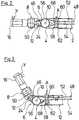
- in einer Prinzipdarstellung ein medizinisch-endoskopisches Instrument gemäß einer zweiten Ausgestaltung,
- Fig. 6
- in einer Prinzipdarstellung ein medizinisch-endoskopisches Instrument gemäß einer dritten Ausgestaltung,
- Fig. 7
- in einer Prinzipdarstellung ein medizinisch-endoskopisches Instrument gemäß einer vierten Ausgestaltung,
- Fig. 8
- in einer Prinzipdarstellung ein medizinisch-endoskopisches Instrument gemäß einer fünften Ausgestaltung und
- Fig. 9
- in einer Prinzipdarstellung ein medizinisch-endoskopisches Instrument gemäß einer sechsten Ausgestaltung.
- Fig. 1
- a perspective view of a distal end section of a medical endoscopic instrument with an angled instrument head,
- Fig. 2
- the distal end portion
Fig. 1 with an instrument head arranged in the longitudinal extension of a shaft in a longitudinal section, - Fig. 3
- the sectional view after
Fig. 2 with angled instrument head, - Fig. 4
- in a schematic representation of the medical endoscopic instrument
Fig. 1 , - Fig. 5
- a schematic representation of a medical endoscopic instrument according to a second embodiment,
- Fig. 6
- a basic representation of a medical endoscopic instrument according to a third embodiment,
- Fig. 7
- a schematic representation of a medical endoscopic instrument according to a fourth embodiment,
- Fig. 8
- a schematic representation of a medical endoscopic instrument according to a fifth embodiment and
- Fig. 9
- a schematic representation of a medical endoscopic instrument according to a sixth embodiment.
Bei dem in der Zeichnung dargestellten medizinisch-endoskopischen Instrument handelt es sich um eine Zange. Dieses Instrument, welches ein manuell zu betätigendes Instrument oder ein in Verbindung mit einem Operationsroboter verwendetes Instrument sein kann, weist einen länglichen, hohlzylindrisch ausgebildeten Schaft 2 auf, wobei in der Zeichnung aus Gründen der besseren Übersichtlichkeit lediglich das distale Ende des Schafts 2 dargestellt ist. Auch die Steuerungseinrichtungen bzw. Antriebe am proximalen Ende des Schafts 2 sind nicht dargestellt, da diese in bekannter Weise ausgebildet sein können.The medical endoscopic instrument shown in the drawing is a pair of pliers. This instrument, which can be a manually operated instrument or an instrument used in connection with an operating robot, has an elongated, hollow-
Das distale Ende des Schafts 2 wird von einem Endstück 4 gebildet. An das Endstück 4 schließt sich distalseitig ein Doppelgelenk 6 an, über welches ein Instrumentenkopf 8 an dem Schaft 2 um eine von einem Gelenkstift 10 gebildete proximale Schwenkachse und um eine von einem Gelenkstift 12 gebildete distale Schwenkachse schwenkbar angelenkt ist. Der Instrumentenkopf 8 bildet einen Werkzeugträger für ein Maulwerkzeug mit zwei relativ zueinander verschwenkbaren Maulteilen 14 und 16.The distal end of the
Das hülsenförmig ausgebildete Endstück 4 des Schafts 2 weist an seinem distalen Ende zwei Vorsprünge 18 und 20 auf, die in Längsverlängerung des Schafts 2 vorstehen und in Richtung quer zur Längsrichtung des Schafts 2 voneinander beabstandet sind. An den Vorsprüngen 18 und 20 ist jeweils ein quer zur Längsausdehnung des Schafts 2 verlaufendes Durchgangsloch ausgebildet, wobei die Durchgangslöcher der beiden Vorsprünge 18 und 20 miteinander fluchten. Diese Durchgangslöcher dienen zur Aufnahme des Gelenkstifts 10, der die proximale Gelenkachse des Doppelgelenks 6 bildet.The sleeve-shaped
Korrespondierend zu den beiden an den Endstück 4 ausgebildeten Vorsprüngen 18 und 20 sind an dem proximalen Ende des Instrumentenkopfs 8 zwei voneinander beabstandete Vorsprünge 22 und 24 ausgebildet, die sich in proximaler Richtung erstrecken. An den Vorsprüngen 22 und 24 sind quer zur Längsausdehnung des Instrumentenkopfs 8 verlaufende und miteinander fluchtende Durchgangslöcher ausgebildet, durch die der die distale Gelenkachse des Doppelgelenks 6 bildende Gelenkstift 12 geführt ist.Corresponding to the two
An den die proximale und distale Gelenkachse des Doppelgelenks 6 bildenden Gelenkstifte 10 und 12 ist außenseitig der Vorsprünge 18 und 22 ein Gelenkteil 26 angelenkt. In ähnlicher Weise ist an den Gelenkstiften 10 und 12 außenseitig der Vorsprünge 20 und 24 ein weiteres Gelenkteil 28 angelenkt. Die Gelenkteile 26 und 28 bilden einen Teil des Doppelgelenks 6 und verbinden des Instrumentenkopf 8 schwenkbeweglich mit dem Schaft 2. Der Instrumentenkopf 8 ist somit relativ zu dem Schaft 2 in einer Ebene normal zu den Mittelachsen der Gelenkstifte 10 und 12 abwinkelbar, wobei sich seine Abwinkelung aus der Summe der Abwinkelung der Gelenkteile 26 und 28 relativ zu dem Schaft 2 und der Abwinkelung des Instrumentenkopfs 8 relativ zu dem Gelenkteilen 26 und 28 ergibt.A
Um eine definierte Abwinkelung des Instrumentenkopfes 8 relativ zu dem Schaft 2 zu ermöglichen, sind das Endstück 4 des Schafts 2 und der Instrumentenkopf 8 über Wälzkörperpaarungen miteinander verbunden. Zur Bildung dieser Wälzkörperpaarungen weisen die distalen Enden der an dem Endstück 4 ausgebildeten Vorsprünge 18 und 20 und die proximalen Enden der an dem Instrumentenkopf 8 ausgebildeten Vorsprünge 22 und 24 jeweils einen Verzahnabschnitt in Form eines Zahnradsegments auf, wobei die an den Vorsprüngen 18 und 20 ausgebildeten Verzahnabschnitte und die an den Vorsprüngen 22 und 24 ausgebildeten Verzahnabschnitte, welche einen identischen Teilkreisdurchmesser aufweisen, miteinander in Eingriff sind.In order to enable a defined angling of the
Wie aus
Jeder der vier zur Bewegungssteuerung des Maulwerkzeugs eingesetzten Seilzüge 30, 32, 34 und 36 wird im Bereich des Doppelgelenks 6 an einem ihm zugeordneten Umlenkrollenpaar umgelenkt. Eines dieser Umlenkrollenpaare, an dem der Seilzug 30 umgelenkt wird, wird von zwei Umlenkrollen 38 und 40 gebildet, wobei die Umlenkrolle 38 außenseitig des Vorsprungs 24 des Instrumentenkopfs 8 auf den Gelenkstift 12 drehbar gelagert ist und die proximalseitig der Umlenkrolle 38 angeordnete Umlenkrolle 40 außenseitig des an dem Endstück 4 des Schafts 2 ausgebildeten Vorsprung 20 drehbar auf dem Gelenkstift 10 gelagert ist. Außenseitig der Umlenkrolle 38 ist auf dem Gelenkstift 12 eine weitere Umlenkrolle 42 drehbar gelagert. Dieser Umlenkrolle 42 bildet zusammen mit einer außenseitig der Umlenkrolle 40 drehbar auf dem Gelenkstift 10 gelagerten Umlenkrolle 44 ein weiteres Umlenkrollenpaar für den Seilzug 34. Aus der Zeichnung nicht ersichtlich, sind korrespondierend zu dem von den Umlenkrollen 38 und 40 gebildeten Umlenkrollenpaar und dem von den Umlenkrollen 42 und 44 gebildeten Umlenkrollenpaar außenseitig des Vorsprungs 22 des Instrumentenkopfs 8 und des Vorsprungs 18 des Endstücks 4 des Schafts 2 weitere Umlenkrollen zur Umlenkung der Seilzüge 32 und 36 angeordnet.Each of the four cable pulls 30, 32, 34 and 36 used to control the movement of the jaw tool is deflected in the region of the double joint 6 on a pair of deflection pulleys assigned to it. One of these pairs of deflection rollers, on which the
An dem Instrumentenkopf 8 ist in dem Zwischenraum zwischen den an dem Instrumentenkopf 8 ausgebildeten proximalen Vorsprüngen 22 und 24 eine Betätigungsscheibe 46 mit einer kreisförmigen Umfangskontur angeordnet (siehe insbesondere
Die Betätigungsscheibe 46 wird distalseitig von einem Seil 48 umschlungen, wobei ein mit dem Seil 48 verbundener Zapfen 50 in eine an der Betätigungsscheibe 46 ausgebildete Ausnehmung eingreift, wodurch das Seil 48 formschlüssig an der Betätigungsscheibe 46 festgelegt ist. Die freien Enden des Seils 48 bilden Seilzüge 52 und 54, welche zur Steuerung der Abwinkelung des Instrumentenkopfs 8 relativ zu dem Schaft 2 dienen. Hierzu sind die Seilzüge 52 und 54 durch den Schaft 2 nach proximalseitig des Schafts 2 geführt, wo sie mit einer Steuerungseinrichtung wirkungsverbunden sind.A
Proximalseitig der Betätigungsscheibe 46 ist auf dem Gelenkstift 10 in dem Zwischenraum zwischen den distalen Vorsprüngen 18 und 20 des Endabschnitts 4 des Schafts 2 eine Führungsrolle 56 drehbar gelagert. An der Führungsrolle 56, welche einen größeren Außendurchmesser als die Betätigungsscheibe 46 aufweist, sind die Seilzüge 52 und 54 an zwei voneinander abgewandten Umfangsbereichen anliegend geführt.On the proximal side of the
In einem Bereich am distalen Ende des Schafts 2 und proximalseitig des Endstücks 4 ist bei allen in der Zeichnung dargestellten Ausführungsbeispielen eine Seilführung 58, 58I, 58II, 58III, 58IV, 59V angeordnet. All diesen Seilführungen 58, 58I, 58II, 58III, 58IV, 59V ist gemeinsam, dass sie zwei in Richtung quer zur Mittelachse X des Schafts 2 voneinander beabstandete Führungsflächen für die Seilzüge 52 und 54 aufweisen, welche von zwei drehbar gelagerten Seilrollen 60 und 62 gebildet werden. Darüber hinaus ist bei allen Seilführungen 58, 58I, 58II, 58III, 58IV, 59V der radiale Abstand voneinander geringer als der Durchmesser der Führungsrolle 56. Die Seilzüge 52 und 54 sind zwischen den Seilrollen 60 und 62 hindurchgeführt, wobei der Seilzug 52 an der der Seilrolle 62 zugewandten Seite der Seilrolle 60 und der Seilzug 54 an der der Seilrolle 60 zugewandten Seite der Seilrolle 62 anliegt.In all the exemplary embodiments shown in the drawing, a
Bei dem in den
Die Bedeutung der Seilführung 58 wird insbesondere aus den
Die Seilführung 58I des in
Bei dem in
Die Seilrollen 60 und 62 der Seilführung 58III des in
Wie bei dem in
Auch bei dem in
- 22nd
- Schaftshaft
- 44th
- EndstückTail
- 66
- DoppelgelenkDouble joint
- 88th
- InstrumentenkopfInstrument head
- 1010th
- GelenkstiftHinge pin
- 1212
- GelenkstiftHinge pin
- 1414
- MaulteilMouth part
- 1616
- MaulteilMouth part
- 1818th
- Vorsprunghead Start
- 2020th
- Vorsprunghead Start
- 2222
- Vorsprunghead Start
- 2424th
- Vorsprunghead Start
- 2626
- GelenkteilJoint part
- 2828
- GelenkteilJoint part
- 3030th
- SeilzugCable
- 3232
- SeilzugCable
- 3434
- SeilzugCable
- 3636
- SeilzugCable
- 3838
- UmlenkrollePulley
- 4040
- UmlenkrollePulley
- 4242
- UmlenkrollePulley
- 4444
- UmlenkrollePulley
- 4646
- BetätigungsscheibeActuating disc
- 4848
- Seilrope
- 5050
- ZapfenCones
- 5252
- SeilzugCable
- 5454
- SeilzugCable
- 5656
- FührungsrolleLeadership role
- 58, 58I, 58II, 58III, 58IV, 59V58, 58I , 58II , 58III , 58IV , 59V
- SeilführungRope guide
- 6060
- SeilrolleRope pulley
- 6262
- SeilrolleRope pulley
- 6464
- VerbindungselementFastener
- 6666
- VerbindungselementFastener
- 6868
- Schlittencarriage
- 7070
- AusnehmungRecess
- 7272
- SchwenklagerSwivel bearing
- 7474
- Auslegerboom
- 7676
- Auslegerboom
- 7878
- Stiftpen
- 8080
- Auslegerboom
- 8282
- Auslegerboom
- 8484
- Auslegerboom
- 8686
- VerbindungselementFastener
- 8888
- Auslegerboom
- 9090
- Stiftpen
- AA
- Richtungdirection
- BB
- Richtungdirection
- CC.
- Richtungdirection
- DD
- Richtungdirection
- EE
- Richtungdirection
- FF
- Richtungdirection
- GG
- Richtungdirection
- HH
- Richtungdirection
- XX
- MittelachseCentral axis
- YY
- StörkraftDisruptive force
Claims (10)
- An instrument, in particular a medical-endoscopic instrument, with a shank (2), with an instrument head (8) which is arranged distally of the shank (2) and which is articulated to the shank (2) via a double joint (6) with two joint axes which are distanced to one another in the longitudinal direction of the instrument, and with two pull cables (52, 54) which are led through the shank (2) and which are connected in movement to the instrument head (8) in an antagonistically acting manner and in the region of the distal end of the shank (2) bear on two guide surfaces of a cable guide (58, 58I, 58II, 58III, 58IV, 59V) which face one another in the radial direction of the shank (2),characterised in that guide surfaces of the cable guide (58, 58I, 58II, 58III, 58IV, 59V) are movable synchronously in the same direction transversely to a middle axis (X) of the shank (2).
- An instrument according to claim 1,characterised in that the guide surfaces are autonomously movable due to a force action upon a pull cable (52, 54) which acts as an antagonist.
- An instrument according to one of the preceding claims,characterised in that the cable guide (58, 58I, 58", 58III, 58IV, 59V) comprises two cable rollers (60, 62) which are distanced to one another in the radial direction of the shank (2) and which each form a guide surface for a pull cable (52, 54).
- An instrument according to one of the preceding claims,characterised in that the cable guide (58, 58I) is displaceable in a direction transverse to the middle axis (X) of the shank (2).
- An instrument according to claim 4,characterised in that the cable guide (58, 58I) comprises a slide (68) which is displaceably guided in a guide which is arranged within the shank (2).
- An instrument according to one of the claims 1 - 3,characterised in that the cable guide (58II, 58III, 58IV, 58V) is pivotable in the direction transverse to the middle axis (X) of the shaft (2).
- An instrument according to claim 6,characterised in that the cable guide (58II, 58III, 58IV, 58V) is pivotable about a pivot axis which is distanced to the cable guide (58II, 58III, 58IV, 58V) in the direction of the middle axis (X) of the shank (2).
- An instrument according to one of the claims 1- 3,characterised in that the cable guide (58I) is pivotable about an axis which is arranged between its guide surfaces.
- An instrument according to one of the preceding claims,characterised in that the cable guide (58I) is displaceable in the radial direction of the shaft (2) as well as pivotable about an axis which is arranged between the guide surfaces of the cable guide (58I).
- An instrument according to one of the preceding claims,characterised in that two recesses (70) for receiving the cable guide (58, 58I, 58II, 58III, 58IV, 58V) are formed on the outer wall of the shank (2) diametrically opposite one another in the movement direction of the cable guide.
Applications Claiming Priority (2)
| Application Number | Priority Date | Filing Date | Title |
|---|---|---|---|
| DE102016208218.3ADE102016208218A1 (en) | 2016-05-12 | 2016-05-12 | Instrument, in particular medical endoscopic instrument |
| PCT/DE2017/200040WO2017194064A1 (en) | 2016-05-12 | 2017-05-09 | Instrument, in particular medical endoscopic instrument |
Publications (2)
| Publication Number | Publication Date |
|---|---|
| EP3454769A1 EP3454769A1 (en) | 2019-03-20 |
| EP3454769B1true EP3454769B1 (en) | 2020-06-10 |
Family
ID=59227423
Family Applications (1)
| Application Number | Title | Priority Date | Filing Date |
|---|---|---|---|
| EP17733349.9AActiveEP3454769B1 (en) | 2016-05-12 | 2017-05-09 | Instrument, in particular medical endososcopic instrument |
Country Status (3)
| Country | Link |
|---|---|
| EP (1) | EP3454769B1 (en) |
| DE (1) | DE102016208218A1 (en) |
| WO (1) | WO2017194064A1 (en) |
Families Citing this family (6)
| Publication number | Priority date | Publication date | Assignee | Title |
|---|---|---|---|---|
| CN112842526B (en)* | 2020-12-31 | 2022-06-03 | 杭州康基医疗器械有限公司 | Be applied to difference compensation mechanism of manipulator |
| CN114010319B (en)* | 2021-09-15 | 2022-09-23 | 苏州中科华影健康科技有限公司 | Endoscopic surgery mechanical device and surgical robot |
| DE102021126892B4 (en) | 2021-10-16 | 2023-08-24 | Karl Storz Se & Co. Kg | MEDICAL INSTRUMENT |
| DE102021126895B4 (en) | 2021-10-16 | 2023-08-31 | Karl Storz Se & Co. Kg | MEDICAL INSTRUMENT |
| DE102021126893B4 (en) | 2021-10-16 | 2023-08-24 | Karl Storz Se & Co. Kg | MEDICAL INSTRUMENT |
| DE102024109223A1 (en)* | 2023-09-09 | 2025-03-13 | Deutsches Zentrum für Luft- und Raumfahrt e.V. | Robotic device for endoscopic inspections |
Family Cites Families (4)
| Publication number | Priority date | Publication date | Assignee | Title |
|---|---|---|---|---|
| EP2732937A4 (en)* | 2011-07-12 | 2015-05-27 | Yaskawa Denki Seisakusho Kk | HAND OF ROBOT, AND ROBOT |
| DE102014206930B4 (en)* | 2014-04-10 | 2023-01-26 | Richard Wolf Gmbh | Instrument, in particular medical endoscopic instrument |
| DE102014219195B4 (en)* | 2014-09-23 | 2024-07-18 | Richard Wolf Gmbh | Instrument, in particular medical-endoscopic shaft instrument |
| US10154841B2 (en)* | 2015-06-18 | 2018-12-18 | Ethicon Llc | Surgical stapling instruments with lockout arrangements for preventing firing system actuation when a cartridge is spent or missing |
- 2016
- 2016-05-12DEDE102016208218.3Apatent/DE102016208218A1/ennot_activeWithdrawn
- 2017
- 2017-05-09WOPCT/DE2017/200040patent/WO2017194064A1/ennot_activeCeased
- 2017-05-09EPEP17733349.9Apatent/EP3454769B1/enactiveActive
Non-Patent Citations (1)
| Title |
|---|
| None* |
Also Published As
| Publication number | Publication date |
|---|---|
| EP3454769A1 (en) | 2019-03-20 |
| DE102016208218A1 (en) | 2017-11-16 |
| WO2017194064A1 (en) | 2017-11-16 |
Similar Documents
| Publication | Publication Date | Title |
|---|---|---|
| EP3454769B1 (en) | Instrument, in particular medical endososcopic instrument | |
| EP3474767B1 (en) | Instrument support device for a manipulator of a robotic surgical system | |
| EP2877100B1 (en) | Shaft for medical instruments, comprising movable sections | |
| DE69835148T2 (en) | SURGICAL CLIPS AND TERMINALS | |
| DE102014217796B4 (en) | Instrument, in particular medical-endoscopic instrument or technoscope | |
| EP0609503B1 (en) | Medical instrument | |
| DE102009042150A1 (en) | Surgical instrument to be used in combination with a trocar or something similar has proximal and distal ends as well as an end section with an articulated zone | |
| EP3076882A1 (en) | Instrument, in particular a medical endoscopic instrument or technoscope | |
| DE4104755A1 (en) | SURGICAL INSTRUMENT | |
| EP2869749A1 (en) | Medical instrument, and method for pivoting such a medical instrument | |
| EP2675386A2 (en) | Surgical instrument | |
| WO2014124846A1 (en) | Instrument, in particular medical endoscopic instrument or technoscope | |
| EP3062680B1 (en) | Deflection movement transmission device, endoscope bend control, and endoscope | |
| EP2106759A1 (en) | Medical instrument with flexible insert | |
| DE102018209087A1 (en) | Control handle device and catheter instrument | |
| EP4376728B1 (en) | Surgical instrument and steering gear for same | |
| DE102014219195B4 (en) | Instrument, in particular medical-endoscopic shaft instrument | |
| DE102016118158B3 (en) | Bendable shaft tube of a medical instrument, medical instrument and method for producing a flexible shaft tube | |
| EP3459473B1 (en) | Instrument | |
| DE102014206930B4 (en) | Instrument, in particular medical endoscopic instrument | |
| EP3800496B1 (en) | Endoscopic instrument | |
| WO2014173409A1 (en) | Instrument, in particular a medical endoscopic instrument or technoscope | |
| DE102014218669A1 (en) | Instrument, in particular medical endoscopic instrument | |
| EP4389023B1 (en) | Steering gear for surgical instrument and surgical instrument equipped with the same | |
| EP3943024B1 (en) | Medical instrument |
Legal Events
| Date | Code | Title | Description |
|---|---|---|---|
| STAA | Information on the status of an ep patent application or granted ep patent | Free format text:STATUS: UNKNOWN | |
| STAA | Information on the status of an ep patent application or granted ep patent | Free format text:STATUS: THE INTERNATIONAL PUBLICATION HAS BEEN MADE | |
| PUAI | Public reference made under article 153(3) epc to a published international application that has entered the european phase | Free format text:ORIGINAL CODE: 0009012 | |
| STAA | Information on the status of an ep patent application or granted ep patent | Free format text:STATUS: REQUEST FOR EXAMINATION WAS MADE | |
| 17P | Request for examination filed | Effective date:20181009 | |
| AK | Designated contracting states | Kind code of ref document:A1 Designated state(s):AL AT BE BG CH CY CZ DE DK EE ES FI FR GB GR HR HU IE IS IT LI LT LU LV MC MK MT NL NO PL PT RO RS SE SI SK SM TR | |
| AX | Request for extension of the european patent | Extension state:BA ME | |
| DAV | Request for validation of the european patent (deleted) | ||
| DAX | Request for extension of the european patent (deleted) | ||
| STAA | Information on the status of an ep patent application or granted ep patent | Free format text:STATUS: EXAMINATION IS IN PROGRESS | |
| 17Q | First examination report despatched | Effective date:20191008 | |
| GRAP | Despatch of communication of intention to grant a patent | Free format text:ORIGINAL CODE: EPIDOSNIGR1 | |
| STAA | Information on the status of an ep patent application or granted ep patent | Free format text:STATUS: GRANT OF PATENT IS INTENDED | |
| INTG | Intention to grant announced | Effective date:20200205 | |
| GRAS | Grant fee paid | Free format text:ORIGINAL CODE: EPIDOSNIGR3 | |
| GRAA | (expected) grant | Free format text:ORIGINAL CODE: 0009210 | |
| STAA | Information on the status of an ep patent application or granted ep patent | Free format text:STATUS: THE PATENT HAS BEEN GRANTED | |
| AK | Designated contracting states | Kind code of ref document:B1 Designated state(s):AL AT BE BG CH CY CZ DE DK EE ES FI FR GB GR HR HU IE IS IT LI LT LU LV MC MK MT NL NO PL PT RO RS SE SI SK SM TR | |
| REG | Reference to a national code | Ref country code:GB Ref legal event code:FG4D Free format text:NOT ENGLISH | |
| REG | Reference to a national code | Ref country code:CH Ref legal event code:EP Ref country code:AT Ref legal event code:REF Ref document number:1278609 Country of ref document:AT Kind code of ref document:T Effective date:20200615 | |
| REG | Reference to a national code | Ref country code:DE Ref legal event code:R096 Ref document number:502017005670 Country of ref document:DE | |
| REG | Reference to a national code | Ref country code:IE Ref legal event code:FG4D Free format text:LANGUAGE OF EP DOCUMENT: GERMAN | |
| REG | Reference to a national code | Ref country code:LT Ref legal event code:MG4D | |
| PG25 | Lapsed in a contracting state [announced via postgrant information from national office to epo] | Ref country code:SE Free format text:LAPSE BECAUSE OF FAILURE TO SUBMIT A TRANSLATION OF THE DESCRIPTION OR TO PAY THE FEE WITHIN THE PRESCRIBED TIME-LIMIT Effective date:20200610 Ref country code:LT Free format text:LAPSE BECAUSE OF FAILURE TO SUBMIT A TRANSLATION OF THE DESCRIPTION OR TO PAY THE FEE WITHIN THE PRESCRIBED TIME-LIMIT Effective date:20200610 Ref country code:GR Free format text:LAPSE BECAUSE OF FAILURE TO SUBMIT A TRANSLATION OF THE DESCRIPTION OR TO PAY THE FEE WITHIN THE PRESCRIBED TIME-LIMIT Effective date:20200911 Ref country code:NO Free format text:LAPSE BECAUSE OF FAILURE TO SUBMIT A TRANSLATION OF THE DESCRIPTION OR TO PAY THE FEE WITHIN THE PRESCRIBED TIME-LIMIT Effective date:20200910 Ref country code:FI Free format text:LAPSE BECAUSE OF FAILURE TO SUBMIT A TRANSLATION OF THE DESCRIPTION OR TO PAY THE FEE WITHIN THE PRESCRIBED TIME-LIMIT Effective date:20200610 | |
| REG | Reference to a national code | Ref country code:NL Ref legal event code:MP Effective date:20200610 | |
| PG25 | Lapsed in a contracting state [announced via postgrant information from national office to epo] | Ref country code:LV Free format text:LAPSE BECAUSE OF FAILURE TO SUBMIT A TRANSLATION OF THE DESCRIPTION OR TO PAY THE FEE WITHIN THE PRESCRIBED TIME-LIMIT Effective date:20200610 Ref country code:RS Free format text:LAPSE BECAUSE OF FAILURE TO SUBMIT A TRANSLATION OF THE DESCRIPTION OR TO PAY THE FEE WITHIN THE PRESCRIBED TIME-LIMIT Effective date:20200610 Ref country code:HR Free format text:LAPSE BECAUSE OF FAILURE TO SUBMIT A TRANSLATION OF THE DESCRIPTION OR TO PAY THE FEE WITHIN THE PRESCRIBED TIME-LIMIT Effective date:20200610 Ref country code:BG Free format text:LAPSE BECAUSE OF FAILURE TO SUBMIT A TRANSLATION OF THE DESCRIPTION OR TO PAY THE FEE WITHIN THE PRESCRIBED TIME-LIMIT Effective date:20200910 | |
| PG25 | Lapsed in a contracting state [announced via postgrant information from national office to epo] | Ref country code:NL Free format text:LAPSE BECAUSE OF FAILURE TO SUBMIT A TRANSLATION OF THE DESCRIPTION OR TO PAY THE FEE WITHIN THE PRESCRIBED TIME-LIMIT Effective date:20200610 Ref country code:AL Free format text:LAPSE BECAUSE OF FAILURE TO SUBMIT A TRANSLATION OF THE DESCRIPTION OR TO PAY THE FEE WITHIN THE PRESCRIBED TIME-LIMIT Effective date:20200610 | |
| PG25 | Lapsed in a contracting state [announced via postgrant information from national office to epo] | Ref country code:CZ Free format text:LAPSE BECAUSE OF FAILURE TO SUBMIT A TRANSLATION OF THE DESCRIPTION OR TO PAY THE FEE WITHIN THE PRESCRIBED TIME-LIMIT Effective date:20200610 Ref country code:RO Free format text:LAPSE BECAUSE OF FAILURE TO SUBMIT A TRANSLATION OF THE DESCRIPTION OR TO PAY THE FEE WITHIN THE PRESCRIBED TIME-LIMIT Effective date:20200610 Ref country code:IT Free format text:LAPSE BECAUSE OF FAILURE TO SUBMIT A TRANSLATION OF THE DESCRIPTION OR TO PAY THE FEE WITHIN THE PRESCRIBED TIME-LIMIT Effective date:20200610 Ref country code:PT Free format text:LAPSE BECAUSE OF FAILURE TO SUBMIT A TRANSLATION OF THE DESCRIPTION OR TO PAY THE FEE WITHIN THE PRESCRIBED TIME-LIMIT Effective date:20201012 Ref country code:ES Free format text:LAPSE BECAUSE OF FAILURE TO SUBMIT A TRANSLATION OF THE DESCRIPTION OR TO PAY THE FEE WITHIN THE PRESCRIBED TIME-LIMIT Effective date:20200610 Ref country code:SM Free format text:LAPSE BECAUSE OF FAILURE TO SUBMIT A TRANSLATION OF THE DESCRIPTION OR TO PAY THE FEE WITHIN THE PRESCRIBED TIME-LIMIT Effective date:20200610 Ref country code:EE Free format text:LAPSE BECAUSE OF FAILURE TO SUBMIT A TRANSLATION OF THE DESCRIPTION OR TO PAY THE FEE WITHIN THE PRESCRIBED TIME-LIMIT Effective date:20200610 | |
| PG25 | Lapsed in a contracting state [announced via postgrant information from national office to epo] | Ref country code:SK Free format text:LAPSE BECAUSE OF FAILURE TO SUBMIT A TRANSLATION OF THE DESCRIPTION OR TO PAY THE FEE WITHIN THE PRESCRIBED TIME-LIMIT Effective date:20200610 Ref country code:PL Free format text:LAPSE BECAUSE OF FAILURE TO SUBMIT A TRANSLATION OF THE DESCRIPTION OR TO PAY THE FEE WITHIN THE PRESCRIBED TIME-LIMIT Effective date:20200610 Ref country code:IS Free format text:LAPSE BECAUSE OF FAILURE TO SUBMIT A TRANSLATION OF THE DESCRIPTION OR TO PAY THE FEE WITHIN THE PRESCRIBED TIME-LIMIT Effective date:20201010 | |
| REG | Reference to a national code | Ref country code:DE Ref legal event code:R097 Ref document number:502017005670 Country of ref document:DE | |
| PLBE | No opposition filed within time limit | Free format text:ORIGINAL CODE: 0009261 | |
| STAA | Information on the status of an ep patent application or granted ep patent | Free format text:STATUS: NO OPPOSITION FILED WITHIN TIME LIMIT | |
| PG25 | Lapsed in a contracting state [announced via postgrant information from national office to epo] | Ref country code:DK Free format text:LAPSE BECAUSE OF FAILURE TO SUBMIT A TRANSLATION OF THE DESCRIPTION OR TO PAY THE FEE WITHIN THE PRESCRIBED TIME-LIMIT Effective date:20200610 | |
| 26N | No opposition filed | Effective date:20210311 | |
| PG25 | Lapsed in a contracting state [announced via postgrant information from national office to epo] | Ref country code:SI Free format text:LAPSE BECAUSE OF FAILURE TO SUBMIT A TRANSLATION OF THE DESCRIPTION OR TO PAY THE FEE WITHIN THE PRESCRIBED TIME-LIMIT Effective date:20200610 | |
| REG | Reference to a national code | Ref country code:CH Ref legal event code:PL | |
| PG25 | Lapsed in a contracting state [announced via postgrant information from national office to epo] | Ref country code:CH Free format text:LAPSE BECAUSE OF NON-PAYMENT OF DUE FEES Effective date:20210531 Ref country code:MC Free format text:LAPSE BECAUSE OF FAILURE TO SUBMIT A TRANSLATION OF THE DESCRIPTION OR TO PAY THE FEE WITHIN THE PRESCRIBED TIME-LIMIT Effective date:20200610 Ref country code:LI Free format text:LAPSE BECAUSE OF NON-PAYMENT OF DUE FEES Effective date:20210531 Ref country code:LU Free format text:LAPSE BECAUSE OF NON-PAYMENT OF DUE FEES Effective date:20210509 | |
| REG | Reference to a national code | Ref country code:BE Ref legal event code:MM Effective date:20210531 | |
| PG25 | Lapsed in a contracting state [announced via postgrant information from national office to epo] | Ref country code:IE Free format text:LAPSE BECAUSE OF NON-PAYMENT OF DUE FEES Effective date:20210509 | |
| PG25 | Lapsed in a contracting state [announced via postgrant information from national office to epo] | Ref country code:BE Free format text:LAPSE BECAUSE OF NON-PAYMENT OF DUE FEES Effective date:20210531 | |
| PG25 | Lapsed in a contracting state [announced via postgrant information from national office to epo] | Ref country code:CY Free format text:LAPSE BECAUSE OF FAILURE TO SUBMIT A TRANSLATION OF THE DESCRIPTION OR TO PAY THE FEE WITHIN THE PRESCRIBED TIME-LIMIT Effective date:20200610 | |
| REG | Reference to a national code | Ref country code:AT Ref legal event code:MM01 Ref document number:1278609 Country of ref document:AT Kind code of ref document:T Effective date:20220509 | |
| PG25 | Lapsed in a contracting state [announced via postgrant information from national office to epo] | Ref country code:HU Free format text:LAPSE BECAUSE OF FAILURE TO SUBMIT A TRANSLATION OF THE DESCRIPTION OR TO PAY THE FEE WITHIN THE PRESCRIBED TIME-LIMIT; INVALID AB INITIO Effective date:20170509 Ref country code:AT Free format text:LAPSE BECAUSE OF NON-PAYMENT OF DUE FEES Effective date:20220509 | |
| PG25 | Lapsed in a contracting state [announced via postgrant information from national office to epo] | Ref country code:MK Free format text:LAPSE BECAUSE OF FAILURE TO SUBMIT A TRANSLATION OF THE DESCRIPTION OR TO PAY THE FEE WITHIN THE PRESCRIBED TIME-LIMIT Effective date:20200610 | |
| PG25 | Lapsed in a contracting state [announced via postgrant information from national office to epo] | Ref country code:MT Free format text:LAPSE BECAUSE OF FAILURE TO SUBMIT A TRANSLATION OF THE DESCRIPTION OR TO PAY THE FEE WITHIN THE PRESCRIBED TIME-LIMIT Effective date:20200610 | |
| PGFP | Annual fee paid to national office [announced via postgrant information from national office to epo] | Ref country code:DE Payment date:20250522 Year of fee payment:9 | |
| PGFP | Annual fee paid to national office [announced via postgrant information from national office to epo] | Ref country code:GB Payment date:20250522 Year of fee payment:9 | |
| PGFP | Annual fee paid to national office [announced via postgrant information from national office to epo] | Ref country code:FR Payment date:20250521 Year of fee payment:9 |