EP3453335B1 - Ablation device with articulated imaging transducer - Google Patents
Ablation device with articulated imaging transducerDownload PDFInfo
- Publication number
- EP3453335B1 EP3453335B1EP18189282.9AEP18189282AEP3453335B1EP 3453335 B1EP3453335 B1EP 3453335B1EP 18189282 AEP18189282 AEP 18189282AEP 3453335 B1EP3453335 B1EP 3453335B1
- Authority
- EP
- European Patent Office
- Prior art keywords
- needle
- tip
- shaft
- tines
- imaging
- Prior art date
- Legal status (The legal status is an assumption and is not a legal conclusion. Google has not performed a legal analysis and makes no representation as to the accuracy of the status listed.)
- Active
Links
Images


Classifications
- A—HUMAN NECESSITIES
- A61—MEDICAL OR VETERINARY SCIENCE; HYGIENE
- A61B—DIAGNOSIS; SURGERY; IDENTIFICATION
- A61B18/00—Surgical instruments, devices or methods for transferring non-mechanical forms of energy to or from the body
- A61B18/04—Surgical instruments, devices or methods for transferring non-mechanical forms of energy to or from the body by heating
- A61B18/12—Surgical instruments, devices or methods for transferring non-mechanical forms of energy to or from the body by heating by passing a current through the tissue to be heated, e.g. high-frequency current
- A61B18/14—Probes or electrodes therefor
- A61B18/1477—Needle-like probes
- A—HUMAN NECESSITIES
- A61—MEDICAL OR VETERINARY SCIENCE; HYGIENE
- A61B—DIAGNOSIS; SURGERY; IDENTIFICATION
- A61B8/00—Diagnosis using ultrasonic, sonic or infrasonic waves
- A61B8/08—Clinical applications
- A61B8/0833—Clinical applications involving detecting or locating foreign bodies or organic structures
- A61B8/0841—Clinical applications involving detecting or locating foreign bodies or organic structures for locating instruments
- A—HUMAN NECESSITIES
- A61—MEDICAL OR VETERINARY SCIENCE; HYGIENE
- A61B—DIAGNOSIS; SURGERY; IDENTIFICATION
- A61B8/00—Diagnosis using ultrasonic, sonic or infrasonic waves
- A61B8/12—Diagnosis using ultrasonic, sonic or infrasonic waves in body cavities or body tracts, e.g. by using catheters
- A—HUMAN NECESSITIES
- A61—MEDICAL OR VETERINARY SCIENCE; HYGIENE
- A61B—DIAGNOSIS; SURGERY; IDENTIFICATION
- A61B8/00—Diagnosis using ultrasonic, sonic or infrasonic waves
- A61B8/44—Constructional features of the ultrasonic, sonic or infrasonic diagnostic device
- A61B8/4444—Constructional features of the ultrasonic, sonic or infrasonic diagnostic device related to the probe
- A61B8/445—Details of catheter construction
- A—HUMAN NECESSITIES
- A61—MEDICAL OR VETERINARY SCIENCE; HYGIENE
- A61B—DIAGNOSIS; SURGERY; IDENTIFICATION
- A61B8/00—Diagnosis using ultrasonic, sonic or infrasonic waves
- A61B8/44—Constructional features of the ultrasonic, sonic or infrasonic diagnostic device
- A61B8/4444—Constructional features of the ultrasonic, sonic or infrasonic diagnostic device related to the probe
- A61B8/4461—Features of the scanning mechanism, e.g. for moving the transducer within the housing of the probe
- A—HUMAN NECESSITIES
- A61—MEDICAL OR VETERINARY SCIENCE; HYGIENE
- A61B—DIAGNOSIS; SURGERY; IDENTIFICATION
- A61B18/00—Surgical instruments, devices or methods for transferring non-mechanical forms of energy to or from the body
- A61B2018/00053—Mechanical features of the instrument of device
- A61B2018/0016—Energy applicators arranged in a two- or three dimensional array
- A—HUMAN NECESSITIES
- A61—MEDICAL OR VETERINARY SCIENCE; HYGIENE
- A61B—DIAGNOSIS; SURGERY; IDENTIFICATION
- A61B18/00—Surgical instruments, devices or methods for transferring non-mechanical forms of energy to or from the body
- A61B2018/00315—Surgical instruments, devices or methods for transferring non-mechanical forms of energy to or from the body for treatment of particular body parts
- A61B2018/00559—Female reproductive organs
- A—HUMAN NECESSITIES
- A61—MEDICAL OR VETERINARY SCIENCE; HYGIENE
- A61B—DIAGNOSIS; SURGERY; IDENTIFICATION
- A61B18/00—Surgical instruments, devices or methods for transferring non-mechanical forms of energy to or from the body
- A61B18/04—Surgical instruments, devices or methods for transferring non-mechanical forms of energy to or from the body by heating
- A61B18/12—Surgical instruments, devices or methods for transferring non-mechanical forms of energy to or from the body by heating by passing a current through the tissue to be heated, e.g. high-frequency current
- A61B18/14—Probes or electrodes therefor
- A61B2018/1405—Electrodes having a specific shape
- A61B2018/1425—Needle
- A61B2018/143—Needle multiple needles
- A—HUMAN NECESSITIES
- A61—MEDICAL OR VETERINARY SCIENCE; HYGIENE
- A61B—DIAGNOSIS; SURGERY; IDENTIFICATION
- A61B18/00—Surgical instruments, devices or methods for transferring non-mechanical forms of energy to or from the body
- A61B18/04—Surgical instruments, devices or methods for transferring non-mechanical forms of energy to or from the body by heating
- A61B18/12—Surgical instruments, devices or methods for transferring non-mechanical forms of energy to or from the body by heating by passing a current through the tissue to be heated, e.g. high-frequency current
- A61B18/14—Probes or electrodes therefor
- A61B2018/1475—Electrodes retractable in or deployable from a housing
- A—HUMAN NECESSITIES
- A61—MEDICAL OR VETERINARY SCIENCE; HYGIENE
- A61B—DIAGNOSIS; SURGERY; IDENTIFICATION
- A61B90/00—Instruments, implements or accessories specially adapted for surgery or diagnosis and not covered by any of the groups A61B1/00 - A61B50/00, e.g. for luxation treatment or for protecting wound edges
- A61B90/36—Image-producing devices or illumination devices not otherwise provided for
- A61B90/37—Surgical systems with images on a monitor during operation
- A61B2090/378—Surgical systems with images on a monitor during operation using ultrasound
- A61B2090/3782—Surgical systems with images on a monitor during operation using ultrasound transmitter or receiver in catheter or minimal invasive instrument
- A61B2090/3784—Surgical systems with images on a monitor during operation using ultrasound transmitter or receiver in catheter or minimal invasive instrument both receiver and transmitter being in the instrument or receiver being also transmitter
Definitions
- the present inventionrelates generally to medical devices and methods. More particularly, the present invention relates to an imaging and therapy device having a deployable treatment needle or needles and a pivotal imaging array.
- Uterine fibroidsare benign tumors in the uterine wall and are the most common tumor of the female pelvis. Fibroids afflict up to 30% of women of childbearing age and can cause significant symptoms including discomfort, pelvic pain, mennorhagia (excessive bleeding), anemia, infertility, and miscarriage. While fibroids may be located in the muscle (intramural), adjacent to the endometrium (submucosal), or in the outer layer of the uterus (subserosal), and can grow up to several centimeters in diameter.
- Surgical interventionsinclude myomectomy, where fibroids are removed in an open surgical procedure requiring laparotomy and general anesthesia, and hysterectomy, involving complete surgical removal of the uterus. Both these procedures are long and have significant blood loss.
- Laparoscopic myomectomyis a laparoscopic procedure requiring highly skilled laparoscopic gynecologists.
- Uterine artery embolizationrelies on blocking the uterine artery supplying blood to the fibroid by injecting small particles. While sometimes effective, common complications of arterial embolization include infection, premature menopause, and severe pelvic pain.
- a third approachrelies on complete endometrial ablation, which is generally effective for treating bleeding but less reliable for treating fibroids.
- US 2007/0249939describes a delivery system including rigid shaft, an imaging core, and an interventional core.
- the rigid delivery shafthas a proximal end, an angled distal tip, and an axial passage therethrough.
- the imaging corecomprises an ultrasound imaging insert disposed within the axial passage.
- the imaging inserthas an ultrasound array within a distal portion thereof, wherein the ultrasound array is tilted relative to a shaft axis.
- the interventional corecomprises a curved ablation needle coupled to the rigid shaft.
- An angle of needle curvaturemay be inversely proportional to the ultrasound array tilt and tip angle
- US5469853describes a bendable ultrasonic probe that bends against a longitudinal direction of the carrier. The bendable portion bends in a direction away from an exit port of a therapy channel enabling an ultrasonic device carried by the bendable portion to be repositioned relative to the therapy channel and the exit port.
- An endosurgical toolmay exit the exit port.
- US2006/0058680describes a guide device for a laparoscopic ultrasound probe.
- the guide deviceincludes a sheath that is adapted to fit over at least a portion of the ultrasound probe, and a guide coupled to the sheath for guiding a medical tool inserted therethrough to position the medical tool in a plane of an ultrasound image obtained via the ultrasound probe.
- the laparoscopic ultrasound probeis flexible so that the distal end thereof can be controlled to bend.
- the present inventionis set out in the appended claims. Described herein are apparatus for imaging and treating fibroids and other tumors and tissue mases located in the walls of a uterus or other body cavity.
- the apparatus and systemscomprise a straight shaft having a distal end and a proximal end.
- a delivery needlepreferably straight, is reciprocatably coupled to the shaft, typically being mounted in a straight lumen in the shaft, so that a tissue-penetrating tip of the needle can be distally advanced from the shaft along an axial path.
- the delivery needlecarries tines forming a needle array, deployable from within the delivery needle.
- a tip or other structureis pivotally attached to the distal end of the shaft and is moveable between a position parallel to the axial path and a position at an acute or right angle relative to the axial path.
- the pivotable tipcarries or comprises an ultrasonic imaging array, and the tip can be oriented to align a field of view of the imaging array with the needle as the needle is advanced along the axial path.
- the combination of a straight shaft, delivery needle, and pivotally attached tip or imaging arrayhas a number of advantages.
- the straight shaft and needlecan be advanced with precision into tissue surrounding the body cavity, where the needle can be made sufficiently strong to resist unwanted deflection of the type which could occur with other needle configurations.
- the use of a delivery needle and shaftalso enables and facilitates the deployment of a needle array, including a plurality of tines, from the delivery needle to increase the volume of tissue being treated with the needle array.
- the pivotable imaging arrayallows straightening of the imaging array to provide a low profile for introduction through the cervix into the uterus, while also allowing reorientation to cover a wide range of viewing fields after entering the uterus or other body cavity to permit locating fibroids and other tumors and to further follow the advance of the needle array into the fibroids or other tumors.
- the delivery needleis for delivery only, and does not provide treatment. In alternative embodiments, the delivery needle may be used for treatment.
- the pivotable tipfurther allows the effective field of view of the ultrasound image to be increased by pivoting the tip, which has the effect of sweeping the ultrasound image. The tip may be pivoted to enhance the view of the delivery needle and/or the needle array, including tines.
- the imaging arraywill be formed on an imaging core, where the imaging core is removably positionable in the straight shaft so that the imaging array extends into the pivotally attached tip.
- the straight shaftwill usually be rigid while the imaging core is relatively flexible, allowing the imaging core to bend at the point where the tip is pivotally attached to the shaft.
- the needle assemblymay be attached directly to the ultrasound probe or the imaging core may be hinged at the point where the tip is pivotally attached to the shaft.
- the delivery needlewill carry a needle array having at least one tine which can be advanced from the delivery needle, usually carrying a plurality of tines, where the tines are reciprocatably attached to the delivery needle to permit deployment and retraction, usually after the delivery needle has been advanced into target tissue.
- a plurality of tineswill usually be arranged to radially diverge from the delivery needle as the tines are distally advanced.
- at least one additional tinemay be reciprocatably mounted on the delivery needle in a range to be advanced axially from the needle, often forming a center axis to a symmetric deployment of radially diverging tines.
- the tinesmay be electrically conductive while the delivery needle itself is electrically non-conductive or insulating.
- the tinesmay be arranged to be connected to a single pole of an electrosurgical power supply in order to provide for monopolar treatment.
- a certain number of the tinesmay be adopted to one pole of the power supply while others are connected to the other pole, providing for bipolar treatment.
- the imaging and therapeutic delivery systemwill further comprise a handle attached to the proximal end of the straight shaft.
- the handlemay include a lever coupled to the pivotally attached distal tip by one or more pull rods. The lever can be pulled or pushed to actuate the pull rod(s) to pivot the tip.
- the handlemay include a first slide mechanism coupled to the delivery needle, where the slide mechanism can be reciprocated to advance and retract the needle along the axial path.
- the tinesmay be reciprocatably attached to the delivery needle and connected to a second slide mechanism on the handle, optionally being disposed on the first slide mechanism itself, to advance and retract the tines relative to the needle.
- a stop structuremay be disposed on the pivotally attached tip so that the stop structure prevents advancement of the needle when the tip is parallel to the axial path of the needle.
- the methodsinclude introducing a straight shaft into the uterus. Uterine fibroids are then located using an ultrasonic imaging transducer carried by or formed as part of a pivotable tip attached to a distal end of the shaft. The tip is pivoted to reposition a field of view of the ultrasonic transducer carried by the tip.
- the tipmay block advancement of the needle when disposed parallel to the shaft (prior to deployment) and allow advancement when pivoted from the parallel orientation.
- a delivery needlemay be axially advanced from the distal tip of the shaft into tissue near or in a uterine fibroid located using the ultrasonic transducer. Advancement of the needle may be observed by the transducer by aligning the field of view with the needle advancement.
- the shaftis introduced to the uterus via a transvaginal and transcervical introduction.
- Locating fibroidsmay comprise manually rotating and translating the shaft to scan the uterine wall with the ultrasonic transducer. Locating may also comprise pivoting the ultrasonic transducer to adjust the field of view.
- an array including a plurality of tinesmay be advanced from the delivery needle after the needle has been advanced into tissue at or near the uterine fibroid. This method will sweep the ultrasound field of view relative to the needle and anatomy to be imaged. The fibroid is then treated by delivering energy from the needle and/or tines into the fibroid, typically radiofrequency energy, including both monopolar and bipolar radiofrequency energy. Usually, the tines will be electrically active to deliver the radiofrequency energy while the delivery needle is electrically non-conductive to limit the distribution of energy in the uterine wall or other tissue being treated.
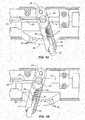
- a tip 18which is adapted to receive an ultrasonic imaging array (shown in broken line at 38) is pivotally attached to a distal end 20 of the hollow rod 14 of the straight shaft assembly 12.
- a needle and tine array 21( Fig. 1B ) is deployed through a lumen or central passage in the needle tube 16 at a distal end 20 of the shaft assembly 12.
- a handle assembly 22is attached to a proximal end 24 of the straight shaft assembly 12 and includes a pivoting mechanism 26, typically found on its lower surface as illustrated, for selectively pivoting the imaging array tip 18 between a low profile configuration where the tip 18 is axially aligned with the axis of the shaft assembly 12, as illustrated in Fig. 1A , and a deflected configuration where the tip 18 is oriented at an acute or right angle relative to the axis of the shaft, as illustrated in Fig. 1B .
- the tip 18may be placed in its axially aligned, low profile configuration for introduction to the body cavity, for example through the cervix into the uterus, and may be shifted to its deflected configuration in order to image tissue and/or to track deployment of the needle/tine array 21.
- the pivoting mechanism 26includes a lever 28 which may be manually retracted from the distally advanced configuration shown in Fig. 1A to the proximally retracted configuration shown in Fig. 1B in order to pivot the tip 18.
- the handle 22will also include a delivery needle/tine deployment mechanism 30 which includes a first slide subassembly 32 and a second slide subassembly 34.
- the handlewill usually further include a port 36 at its proximal end.
- Port 36allows introduction of an ultrasonic or other imaging core, where the imaging core has an imaging array 38, typically an ultrasonic imaging array as described in detail in copending Application Nos. 11/620,594 ; 11/620,569 ; and 11/564,164 , published as US2007/017938 , US2007/0161905 and US2007/0249936 respectively.
- the proximal end of the handlewill also allow electrical connections to be made to the needle/tine array. Additionally, the distal end of the handle will provide a standard luer connection for the infusion of non-conductive coupling fluids.
- a stop structure 19is attached to an upper surface of the pivotally attached tip 18, as illustrated in Figs. 2B and 2C .
- the stop structure 19will block the advancement path of the needle 16 (as shown in Fig. 2B ). This is advantageous since it prevents accidental needle advancement while the shaft assembly 12 is in the introductory configuration. Deployment of the tip 18, as shown in Fig. 2C , moves the stop structure 19 out of the advancement path of the needle 16, as described below.
- FIG. 2For clarity, components of the first slide assembly 32 and second slide assembly 34 have been removed from the view in Fig. 2 .
- the tip 18is pivotally attached at the distal end 20 of the straight shaft assembly 12 by a pivot pin 40 or similar structure, as best seen in Fig. 2A .
- a pair of pull rods 42are attached at anchors 44 so that drawing the wires in a proximal direction will deflect the tip 18 from an axially aligned configuration, as shown in broken line in Fig.
- the rods 42extend through tubes 46 disposed on each side of the hollow rod 14 of the shaft assembly 12. As best seen in Figs. 3A and 3B , the rods 42 are attached at their proximal ends to a rotating anchor 50 disposed in lever 28.
- a rotating anchor 50disposed in lever 28.
- the tip 18may be laterally deflected, as shown in full line in Fig. 2A .
- the tip 18may be returned to the axially aligned configuration as shown in broken line in Fig. 2A .
- the lever 28is pivotally attached to the body of handle 22 by a pivot pin 48 so that the anchor 50 is offset from the point of rotation of the lever 28.
- the anchor 50is actually translated as the lever is rotated back and forth about the pivot pin 48.
- a locking pin 52allows the lever 28 to be selectively locked in place to hold the pivot tip 18 in a fixed orientation.
- Locking pin 52is mounted in a central passage 54 of the lever 28 and carries a pin 56 which seats in one of a plurality of pockets 58 formed in an arcurate locking strip 60.
- the lever 28can be released by pressing the pin 52 against spring 62 so that the pin 56 is lifted out of the pocket 58, as shown in Fig. 3A .
- the levermay be moved freely back and forth to deploy the tip 18.
- the locking pin 52may be released to permit pin 56 to engage the closest pocket 58 where it is held in place by spring 62.
- the lever 28will typically be advanced forwardly to close the tip 18 to a low profile configuration for introducing the imaging and therapy delivery system 10 to the patient for treatment, for example through the cervix into the uterus. Once in place, the lever 28 can be unlocked using the locking pin 52 and oriented to a desired angle relative to the shaft assembly 12 to permit imaging and, in particular, to allow advancement of the delivery needle 70 in the tissue to be observed.
- Figs. 4A-4Cuse of the lever 28 for deflecting the tip 18 is illustrated.
- the tip 18is axially aligned with the axis of the shaft assembly 12 and the lever 28 is in its forward or distal-most position, as shown in Fig. 4A .
- lever 28may be drawn proximally as indicated by the adjacent arrow, to deflect the tip 18 away from the axis of shaft 12, as shown by the arrow adjacent the tip in Fig. 4B .
- the lever 28reaches its fully proximal position, as shown in Fig. 4C , the tip 18 has been fully deflected away from the axis of shaft assembly 12.
- slide subassemblies 32 and 34for extending delivery needle 70 and needle array 21 have not been activated in Figs. 4A-4B .
- FIGs. 5-10operation of the first slide subassembly 32 and the second slide subassembly 34 will be described. For clarity, portions of the pivot mechanism 26 have been removed from these views. Prior to deployment, as shown in Figs. 5 and 6 , the needle/tine array 21 is fully drawn into the central passage of needle tube 16. Needle tube 16 has an open distal tip 64 through which the delivery needle and tines will emerge when advanced using the slide subassemblies 32 and 34.
- the first slide subassembly 32comprises a reciprocating carriage 66 having a coupling 68 attached to a proximal end of the needle 70.
- the carriage 66may be axially advanced and retracted by manually pressing buttons 72 to disengage pins 74 ( Fig. 5 ) from pockets 76 in a straight locking strip 78. Once the pins 74 are disengaged, the carriage 66 may be distally advanced, as shown in Figs. 7 and 8 , to advance tip 80 of needle 70 from the distal end of the needle tube 16.
- the buttons 72may then be released to allow pins 74 to reenter the adjacent pockets 76 in the locking strip 78, thus locking the needle 70 in place.
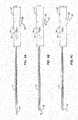
- a plurality of radially diverging tines 82may be deployed from the distal end of needle 70 using the second slide subassembly 34 which includes a thumb slide 84.
- the thumb slide 84is reciprocatably carried in the carriage 66 so that the thumb slide will advance the tines relative to the needle.
- the thumb slideis connected to a tine rod 86 which enters a hollow central passage or lumen of the needle 70 and is coupled to the plurality of tines 82 so that advancement of the thumb slide 84 from the retracted position shown in Figs. 7 and 8 to the distally advanced position shown in Figs. 9 and 10 causes the tines 82 to emerge from the distal end of the needle 70.
- the tines 82are preferably formed from a straight, resilient metal, such as stainless steel, nickel titanium, or the like, and are deflected outwardly by ramps (not shown) in the distal end of the needle.
- a lockout circuit(not shown) may be provided to prevent energizing the tines if the tines are not fully advanced.
- Figs. 11A and 11BThe use of the imaging and therapeutic delivery system 10 of the present invention is illustrated in Figs. 11A and 11B .
- the needle 70is advanced into target tissue identified by the imaging using the first slide subassembly 32, as shown in Fig. 11A .
- the position of the tip 18will be adjusted to assure that travel of the needle 70 into the tissue may be observed.
- the thumb slide 84 of the second slide subassembly 34may then be advanced, as shown in Fig. 11B , to extend the tines 82 into the tissue.
- the needle 70 and tines 82will be rotatably connected to the remainder of the device to allow the handle to be rotated, thus rotating the imaging array 38, to facilitate imaging even after the needle and tines have been deployed.
Landscapes
- Health & Medical Sciences (AREA)
- Life Sciences & Earth Sciences (AREA)
- Engineering & Computer Science (AREA)
- Surgery (AREA)
- Public Health (AREA)
- Animal Behavior & Ethology (AREA)
- Veterinary Medicine (AREA)
- Nuclear Medicine, Radiotherapy & Molecular Imaging (AREA)
- Biomedical Technology (AREA)
- Heart & Thoracic Surgery (AREA)
- Medical Informatics (AREA)
- Molecular Biology (AREA)
- Physics & Mathematics (AREA)
- General Health & Medical Sciences (AREA)
- Pathology (AREA)
- Biophysics (AREA)
- Radiology & Medical Imaging (AREA)
- Plasma & Fusion (AREA)
- Otolaryngology (AREA)
- Surgical Instruments (AREA)
- Ultra Sonic Daignosis Equipment (AREA)
Description
- 1.Field of the Invention. The present invention relates generally to medical devices and methods. More particularly, the present invention relates to an imaging and therapy device having a deployable treatment needle or needles and a pivotal imaging array.
- Uterine fibroids are benign tumors in the uterine wall and are the most common tumor of the female pelvis. Fibroids afflict up to 30% of women of childbearing age and can cause significant symptoms including discomfort, pelvic pain, mennorhagia (excessive bleeding), anemia, infertility, and miscarriage. While fibroids may be located in the muscle (intramural), adjacent to the endometrium (submucosal), or in the outer layer of the uterus (subserosal), and can grow up to several centimeters in diameter.
- Current treatments for fibroids include both pharmaceutical and surgical intervention. Pharmaceutical treatments include the administration of NSAIDS, estrogen-progesterone combinations, and the like. Medications, however, are generally ineffective and are palliative rather than curative. Surgical interventions include myomectomy, where fibroids are removed in an open surgical procedure requiring laparotomy and general anesthesia, and hysterectomy, involving complete surgical removal of the uterus. Both these procedures are long and have significant blood loss.
- As improvements over open surgical procedures, several minimally invasive procedures have been developed. Laparoscopic myomectomy is a laparoscopic procedure requiring highly skilled laparoscopic gynecologists. Uterine artery embolization relies on blocking the uterine artery supplying blood to the fibroid by injecting small particles. While sometimes effective, common complications of arterial embolization include infection, premature menopause, and severe pelvic pain. A third approach relies on complete endometrial ablation, which is generally effective for treating bleeding but less reliable for treating fibroids.
- More recently, and of particular interest to the present invention, the use of radio frequency needles and other ablation elements for treating individual fibroids via a transvaginal approach has been proposed. As described, for example, in published
U.S. Patent Applications 2006/0189972 ;2007/0179380 ;2007/0249936 ; and2008/0033493 , each of which is commonly assigned with the present application, a probe carrying a curved needle is used to treat individual fibroids. The probe carries on-board ultrasonic or other imaging so that the needle can be guided into the fibroid under direct observation. While highly effective in many cases, accurate advancement of a curved needle into a fibroid can be problematic. Moreover, use of a single needle does not always deliver sufficient energy to fully ablate relatively large fibroids. - For these reasons, it would be desirable to provide alternative devices and methods for treating, ablating, or removing uterine fibroids and other tissue masses. It would be particularly desirable if such methods and devices were able to treat uterine fibroids which are large, difficult to penetrate, or which otherwise resist treatment with curved and laterally deployed needles. At least some of these objectives will be met by the inventions described below.
- 2.Brief Description of the Background Art. The following US published applications discussed above are relevant to the present invention:
2006/0189972 ;2007/0179380 ;200710249936 2008/0033493 . US 2007/0249939 describes a delivery system including rigid shaft, an imaging core, and an interventional core. The rigid delivery shaft has a proximal end, an angled distal tip, and an axial passage therethrough. The imaging core comprises an ultrasound imaging insert disposed within the axial passage. The imaging insert has an ultrasound array within a distal portion thereof, wherein the ultrasound array is tilted relative to a shaft axis. The interventional core comprises a curved ablation needle coupled to the rigid shaft. An angle of needle curvature may be inversely proportional to the ultrasound array tilt and tip angleUS5469853 describes a bendable ultrasonic probe that bends against a longitudinal direction of the carrier. The bendable portion bends in a direction away from an exit port of a therapy channel enabling an ultrasonic device carried by the bendable portion to be repositioned relative to the therapy channel and the exit port. An endosurgical tool may exit the exit port.US2006/0058680 describes a guide device for a laparoscopic ultrasound probe. The guide device includes a sheath that is adapted to fit over at least a portion of the ultrasound probe, and a guide coupled to the sheath for guiding a medical tool inserted therethrough to position the medical tool in a plane of an ultrasound image obtained via the ultrasound probe. The laparoscopic ultrasound probe is flexible so that the distal end thereof can be controlled to bend.- The present invention is set out in the appended claims. Described herein are apparatus for imaging and treating fibroids and other tumors and tissue mases located in the walls of a uterus or other body cavity. The apparatus and systems comprise a straight shaft having a distal end and a proximal end. A delivery needle, preferably straight, is reciprocatably coupled to the shaft, typically being mounted in a straight lumen in the shaft, so that a tissue-penetrating tip of the needle can be distally advanced from the shaft along an axial path. The delivery needle carries tines forming a needle array, deployable from within the delivery needle. A tip or other structure is pivotally attached to the distal end of the shaft and is moveable between a position parallel to the axial path and a position at an acute or right angle relative to the axial path. The pivotable tip carries or comprises an ultrasonic imaging array, and the tip can be oriented to align a field of view of the imaging array with the needle as the needle is advanced along the axial path.
- The combination of a straight shaft, delivery needle, and pivotally attached tip or imaging array has a number of advantages. The straight shaft and needle can be advanced with precision into tissue surrounding the body cavity, where the needle can be made sufficiently strong to resist unwanted deflection of the type which could occur with other needle configurations. The use of a delivery needle and shaft also enables and facilitates the deployment of a needle array, including a plurality of tines, from the delivery needle to increase the volume of tissue being treated with the needle array. The pivotable imaging array allows straightening of the imaging array to provide a low profile for introduction through the cervix into the uterus, while also allowing reorientation to cover a wide range of viewing fields after entering the uterus or other body cavity to permit locating fibroids and other tumors and to further follow the advance of the needle array into the fibroids or other tumors. It should be noted that in the preferred embodiment, the delivery needle is for delivery only, and does not provide treatment. In alternative embodiments, the delivery needle may be used for treatment. The pivotable tip further allows the effective field of view of the ultrasound image to be increased by pivoting the tip, which has the effect of sweeping the ultrasound image. The tip may be pivoted to enhance the view of the delivery needle and/or the needle array, including tines.
- In the preferred embodiment, the imaging array will be formed on an imaging core, where the imaging core is removably positionable in the straight shaft so that the imaging array extends into the pivotally attached tip. The straight shaft will usually be rigid while the imaging core is relatively flexible, allowing the imaging core to bend at the point where the tip is pivotally attached to the shaft. In alternate embodiments, the needle assembly may be attached directly to the ultrasound probe or the imaging core may be hinged at the point where the tip is pivotally attached to the shaft.
- The delivery needle will carry a needle array having at least one tine which can be advanced from the delivery needle, usually carrying a plurality of tines, where the tines are reciprocatably attached to the delivery needle to permit deployment and retraction, usually after the delivery needle has been advanced into target tissue. A plurality of tines will usually be arranged to radially diverge from the delivery needle as the tines are distally advanced. Optionally, at least one additional tine may be reciprocatably mounted on the delivery needle in a range to be advanced axially from the needle, often forming a center axis to a symmetric deployment of radially diverging tines. In order to localize the treatment, the tines may be electrically conductive while the delivery needle itself is electrically non-conductive or insulating. In such cases, the tines may be arranged to be connected to a single pole of an electrosurgical power supply in order to provide for monopolar treatment. Alternatively, a certain number of the tines may be adopted to one pole of the power supply while others are connected to the other pole, providing for bipolar treatment.
- In certain exemplary embodiments, the imaging and therapeutic delivery system will further comprise a handle attached to the proximal end of the straight shaft. The handle may include a lever coupled to the pivotally attached distal tip by one or more pull rods. The lever can be pulled or pushed to actuate the pull rod(s) to pivot the tip. Additionally, the handle may include a first slide mechanism coupled to the delivery needle, where the slide mechanism can be reciprocated to advance and retract the needle along the axial path. In the embodiments which include the plurality of tines, the tines may be reciprocatably attached to the delivery needle and connected to a second slide mechanism on the handle, optionally being disposed on the first slide mechanism itself, to advance and retract the tines relative to the needle. Optionally, a stop structure may be disposed on the pivotally attached tip so that the stop structure prevents advancement of the needle when the tip is parallel to the axial path of the needle.
- Also disclosed are methods for treating uterine fibroids. The methods include introducing a straight shaft into the uterus. Uterine fibroids are then located using an ultrasonic imaging transducer carried by or formed as part of a pivotable tip attached to a distal end of the shaft. The tip is pivoted to reposition a field of view of the ultrasonic transducer carried by the tip. Optionally, the tip may block advancement of the needle when disposed parallel to the shaft (prior to deployment) and allow advancement when pivoted from the parallel orientation. A delivery needle may be axially advanced from the distal tip of the shaft into tissue near or in a uterine fibroid located using the ultrasonic transducer. Advancement of the needle may be observed by the transducer by aligning the field of view with the needle advancement.
- In preferred aspects of the methods, the shaft is introduced to the uterus via a transvaginal and transcervical introduction. Locating fibroids may comprise manually rotating and translating the shaft to scan the uterine wall with the ultrasonic transducer. Locating may also comprise pivoting the ultrasonic transducer to adjust the field of view. Optionally, an array including a plurality of tines may be advanced from the delivery needle after the needle has been advanced into tissue at or near the uterine fibroid. This method will sweep the ultrasound field of view relative to the needle and anatomy to be imaged. The fibroid is then treated by delivering energy from the needle and/or tines into the fibroid, typically radiofrequency energy, including both monopolar and bipolar radiofrequency energy. Usually, the tines will be electrically active to deliver the radiofrequency energy while the delivery needle is electrically non-conductive to limit the distribution of energy in the uterine wall or other tissue being treated.
Figs. 1A and1B are perspective views of an imaging and therapeutic delivery system constructed in accordance with the principles of the present invention shown with portions broken away. InFig. 1A , a delivery needle and array including radially diverging tines are retracted within the shaft of the device, and a pivotally attached tip is shown in axial alignment with the axial deployment path of the needle. InFig. 1B , the delivery needle and associated tines are shown in their deployed configuration with the pivotally attached tip shown oriented at an acute angle relative to the axial advancement path of the needle.Fig. 2 illustrates the imaging and therapeutic delivery system ofFigs. 1A and1B in cross-section.Fig. 2A is a detail of the distal tip of the device illustrated inFig. 2 .Figs. 2B and 2C illustrate a stop structure on the pivotally attached tip which prevents needle advancement prior to deployment of the tip.Figs. 3A and 3B illustrate the pivotal tip deployment mechanism in detail, also in cross-section.Figs. 4A-4C illustrate the relative movement of the deployment mechanism and the pivotal tip, as the deployment mechanism is actuated.Figs. 5 and 6 are side and top views of the imaging and therapeutic delivery system shown with portions broken away in a non-deployed configuration.Figs. 7 and 8 are views similar toFigs. 5 and 6 , except that the delivery needle has been deployed and the pivotally attached tip has been positioned at an acute angle.Figs. 9 and 10 are views similar toFigs. 5 and 6 andFigs. 7 and 8 , respectively, further illustrating the deployment of the needle array, comprising radially diverging tines from the delivery needle.Figs. 11A and 11B illustrate deployment of the delivery needle and tines into tissue.- Referring to
Figs. 1A and1B , an imaging and therapeutic delivery system constructed in accordance with the principles of the present invention comprises astraight shaft assembly 12 including ahollow rod 14 and aneedle tube 16. Atip 18 which is adapted to receive an ultrasonic imaging array (shown in broken line at 38) is pivotally attached to adistal end 20 of thehollow rod 14 of thestraight shaft assembly 12. A needle and tine array 21 (Fig. 1B ) is deployed through a lumen or central passage in theneedle tube 16 at adistal end 20 of theshaft assembly 12. Ahandle assembly 22 is attached to aproximal end 24 of thestraight shaft assembly 12 and includes apivoting mechanism 26, typically found on its lower surface as illustrated, for selectively pivoting theimaging array tip 18 between a low profile configuration where thetip 18 is axially aligned with the axis of theshaft assembly 12, as illustrated inFig. 1A , and a deflected configuration where thetip 18 is oriented at an acute or right angle relative to the axis of the shaft, as illustrated inFig. 1B . Thetip 18 may be placed in its axially aligned, low profile configuration for introduction to the body cavity, for example through the cervix into the uterus, and may be shifted to its deflected configuration in order to image tissue and/or to track deployment of the needle/tine array 21. As described in more detail below, thepivoting mechanism 26 includes alever 28 which may be manually retracted from the distally advanced configuration shown inFig. 1A to the proximally retracted configuration shown inFig. 1B in order to pivot thetip 18. - The
handle 22 will also include a delivery needle/tine deployment mechanism 30 which includes afirst slide subassembly 32 and asecond slide subassembly 34. The handle will usually further include aport 36 at its proximal end.Port 36 allows introduction of an ultrasonic or other imaging core, where the imaging core has animaging array 38, typically an ultrasonic imaging array as described in detail in copending Application Nos.11/620,594 11/620,569 11/564,164 US2007/017938 ,US2007/0161905 andUS2007/0249936 respectively. The proximal end of the handle will also allow electrical connections to be made to the needle/tine array. Additionally, the distal end of the handle will provide a standard luer connection for the infusion of non-conductive coupling fluids. - A
stop structure 19 is attached to an upper surface of the pivotally attachedtip 18, as illustrated inFigs. 2B and 2C . When thetip 18 is parallel to the axis of the shaft (hollow rod 14), thestop structure 19 will block the advancement path of the needle 16 (as shown inFig. 2B ). This is advantageous since it prevents accidental needle advancement while theshaft assembly 12 is in the introductory configuration. Deployment of thetip 18, as shown inFig. 2C , moves thestop structure 19 out of the advancement path of theneedle 16, as described below. - Referring now to
Figs. 2 ,2A ,3A, and 3B , operation of thepivot mechanism 26 for selectively deflecting thetip 18 disposed at the distal end of thestraight shaft assembly 12 will be described. For clarity, components of thefirst slide assembly 32 andsecond slide assembly 34 have been removed from the view inFig. 2 . Thetip 18 is pivotally attached at thedistal end 20 of thestraight shaft assembly 12 by apivot pin 40 or similar structure, as best seen inFig. 2A . A pair ofpull rods 42 are attached at anchors 44 so that drawing the wires in a proximal direction will deflect thetip 18 from an axially aligned configuration, as shown in broken line inFig. 2A , to the deflected configuration, as shown in full line inFig. 2A . Therods 42 extend throughtubes 46 disposed on each side of thehollow rod 14 of theshaft assembly 12. As best seen inFigs. 3A and 3B , therods 42 are attached at their proximal ends to arotating anchor 50 disposed inlever 28. Thus, by drawing thelever 28 proximally, as shown inFig. 3A , thetip 18 may be laterally deflected, as shown in full line inFig. 2A . Conversely, by pushing thelever 28 in a distal direction, as shown inFig. 3B , thetip 18 may be returned to the axially aligned configuration as shown in broken line inFig. 2A . Thelever 28 is pivotally attached to the body ofhandle 22 by apivot pin 48 so that theanchor 50 is offset from the point of rotation of thelever 28. Thus, theanchor 50 is actually translated as the lever is rotated back and forth about thepivot pin 48. - A locking
pin 52 allows thelever 28 to be selectively locked in place to hold thepivot tip 18 in a fixed orientation. Lockingpin 52 is mounted in acentral passage 54 of thelever 28 and carries apin 56 which seats in one of a plurality ofpockets 58 formed in anarcurate locking strip 60. Thus, thelever 28 can be released by pressing thepin 52 againstspring 62 so that thepin 56 is lifted out of thepocket 58, as shown inFig. 3A . In this configuration, the lever may be moved freely back and forth to deploy thetip 18. When thetip 18 is in its desired location, the lockingpin 52 may be released to permitpin 56 to engage theclosest pocket 58 where it is held in place byspring 62. It will be appreciated that thelever 28 will typically be advanced forwardly to close thetip 18 to a low profile configuration for introducing the imaging andtherapy delivery system 10 to the patient for treatment, for example through the cervix into the uterus. Once in place, thelever 28 can be unlocked using thelocking pin 52 and oriented to a desired angle relative to theshaft assembly 12 to permit imaging and, in particular, to allow advancement of thedelivery needle 70 in the tissue to be observed. - Referring now to
Figs. 4A-4C , use of thelever 28 for deflecting thetip 18 is illustrated. Initially, thetip 18 is axially aligned with the axis of theshaft assembly 12 and thelever 28 is in its forward or distal-most position, as shown inFig. 4A . By depressing lockingpin 52, as shown inFig. 4B ,lever 28 may be drawn proximally as indicated by the adjacent arrow, to deflect thetip 18 away from the axis ofshaft 12, as shown by the arrow adjacent the tip inFig. 4B . When thelever 28 reaches its fully proximal position, as shown inFig. 4C , thetip 18 has been fully deflected away from the axis ofshaft assembly 12. Note thatslide subassemblies 32 and 34 (for extendingdelivery needle 70 and needle array 21) have not been activated inFigs. 4A-4B . - Referring now to
Figs. 5-10 , operation of thefirst slide subassembly 32 and thesecond slide subassembly 34 will be described. For clarity, portions of thepivot mechanism 26 have been removed from these views. Prior to deployment, as shown inFigs. 5 and 6 , the needle/tine array 21 is fully drawn into the central passage ofneedle tube 16.Needle tube 16 has an opendistal tip 64 through which the delivery needle and tines will emerge when advanced using theslide subassemblies - The
first slide subassembly 32 comprises a reciprocatingcarriage 66 having acoupling 68 attached to a proximal end of theneedle 70. Thecarriage 66 may be axially advanced and retracted by manually pressingbuttons 72 to disengage pins 74 (Fig. 5 ) frompockets 76 in astraight locking strip 78. Once thepins 74 are disengaged, thecarriage 66 may be distally advanced, as shown inFigs. 7 and 8 , to advancetip 80 ofneedle 70 from the distal end of theneedle tube 16. Thebuttons 72 may then be released to allowpins 74 to reenter theadjacent pockets 76 in the lockingstrip 78, thus locking theneedle 70 in place. - Referring now in particular to
Figs. 9 and 10 , a plurality of radially divergingtines 82 may be deployed from the distal end ofneedle 70 using thesecond slide subassembly 34 which includes athumb slide 84. Thethumb slide 84 is reciprocatably carried in thecarriage 66 so that the thumb slide will advance the tines relative to the needle. The thumb slide is connected to atine rod 86 which enters a hollow central passage or lumen of theneedle 70 and is coupled to the plurality oftines 82 so that advancement of thethumb slide 84 from the retracted position shown inFigs. 7 and 8 to the distally advanced position shown inFigs. 9 and 10 causes thetines 82 to emerge from the distal end of theneedle 70. Thetines 82 are preferably formed from a straight, resilient metal, such as stainless steel, nickel titanium, or the like, and are deflected outwardly by ramps (not shown) in the distal end of the needle. Optionally, a lockout circuit (not shown) may be provided to prevent energizing the tines if the tines are not fully advanced. - The use of the imaging and
therapeutic delivery system 10 of the present invention is illustrated inFigs. 11A and 11B . After imaging using theimaging array 38 carried on or intip 18, theneedle 70 is advanced into target tissue identified by the imaging using thefirst slide subassembly 32, as shown inFig. 11A . Usually, the position of thetip 18 will be adjusted to assure that travel of theneedle 70 into the tissue may be observed. After the location of theneedle tip 80 has been confirmed, thethumb slide 84 of thesecond slide subassembly 34 may then be advanced, as shown inFig. 11B , to extend thetines 82 into the tissue. In the preferred embodiments of the present invention, theneedle 70 andtines 82 will be rotatably connected to the remainder of the device to allow the handle to be rotated, thus rotating theimaging array 38, to facilitate imaging even after the needle and tines have been deployed. - While the above is a complete description of the preferred embodiments of the invention, various alternatives, modifications, and equivalents may be used. Therefore, the above description should not be taken as limiting the scope of the invention which is defined by the appended claims.
Claims (11)
- An imaging and therapeutic delivery system comprising:a straight shaft (12) having a distal end and a proximal end;a needle (70) reciprocatably coupled to the shaft so that a tissue-penetrating tip on the needle can be distally advanced from the shaft along an axial path;a tip (18) pivotally attached to the distal end of the shaft and movable between a position parallel to the axial path and a position at an acute or right angle relative to the axial path, wherein the tip (18) includes a stop structure (19) disposed thereon so that the stop structure (19) prevents advancement of the needle (70) when the tip (18) is parallel to the axial path, and wherein deployment of the tip (18) moves the stop structure (19) out of the advancement path of the needle (70); andan ultrasonic imaging array (38) carried by the pivotally attached tip (18), wherein the tip can be oriented to align a field of view of the imaging array with the needle (70) as the needle is advanced along the axial path so as to sweep the ultrasound field of view relative to the needle and anatomy to be imaged,the system further comprising a plurality of tines (82) carried by the needle (70), wherein the tines are reciprocatably attached to the needle.
- A system as in claim 1, wherein the tip (18) is offset from the axial path of the needle (70).
- A system as in claim 1 or 2, further comprising an imaging core which includes the imaging array (38) near a distal end thereof, wherein the imaging core is removably positionable in the straight shaft (12) so that the imaging array extends into the pivotally attached tip (18).
- A system as in claim 3, wherein the straight shaft (12) is relatively rigid and the imaging core is flexible, wherein the imaging core can bend at the point where the tip is pivotally attached to the shaft.
- A system as in claim 3, wherein the straight shaft (12) is relatively rigid and the imaging core is hinged at the point where the tip is pivotally attached to the shaft.
- A system as in claim 1, wherein the ultrasonic imaging array is configured to sweep the ultrasound field of view relative to the anatomy, needle (70) and plurality of tines (82).
- A system as in any of the preceding claims, wherein the tines (82) are arranged to radially diverge from the needle (70) as they are advanced distally.
- A system as in claim 7, wherein at least one additional tine is arranged to advance axially from the needle (70).
- A system as in any of the preceding claims, wherein the needle (70) is electrically non-conductive and the tines (82) are electrically conductive.
- A system as in any one of the preceding claims, wherein rotation of said ultrasonic imaging array is independent of movement of said needle (70).
- A system as in any one of the preceding claims, wherein the needle (70) is reciprocatably deployed in the shaft (12).
Applications Claiming Priority (3)
| Application Number | Priority Date | Filing Date | Title |
|---|---|---|---|
| US12/198,861US20100056926A1 (en) | 2008-08-26 | 2008-08-26 | Ablation device with articulated imaging transducer |
| EP09812027.2AEP2328479B1 (en) | 2008-08-26 | 2009-08-25 | Ablation device with articulated imaging transducer |
| PCT/US2009/054956WO2010027820A1 (en) | 2008-08-26 | 2009-08-25 | Ablation device with articulated imaging transducer |
Related Parent Applications (2)
| Application Number | Title | Priority Date | Filing Date |
|---|---|---|---|
| EP09812027.2ADivisionEP2328479B1 (en) | 2008-08-26 | 2009-08-25 | Ablation device with articulated imaging transducer |
| EP09812027.2ADivision-IntoEP2328479B1 (en) | 2008-08-26 | 2009-08-25 | Ablation device with articulated imaging transducer |
Publications (2)
| Publication Number | Publication Date |
|---|---|
| EP3453335A1 EP3453335A1 (en) | 2019-03-13 |
| EP3453335B1true EP3453335B1 (en) | 2021-05-19 |
Family
ID=41726434
Family Applications (2)
| Application Number | Title | Priority Date | Filing Date |
|---|---|---|---|
| EP18189282.9AActiveEP3453335B1 (en) | 2008-08-26 | 2009-08-25 | Ablation device with articulated imaging transducer |
| EP09812027.2AActiveEP2328479B1 (en) | 2008-08-26 | 2009-08-25 | Ablation device with articulated imaging transducer |
Family Applications After (1)
| Application Number | Title | Priority Date | Filing Date |
|---|---|---|---|
| EP09812027.2AActiveEP2328479B1 (en) | 2008-08-26 | 2009-08-25 | Ablation device with articulated imaging transducer |
Country Status (4)
| Country | Link |
|---|---|
| US (1) | US20100056926A1 (en) |
| EP (2) | EP3453335B1 (en) |
| ES (2) | ES2700864T3 (en) |
| WO (1) | WO2010027820A1 (en) |
Families Citing this family (29)
| Publication number | Priority date | Publication date | Assignee | Title |
|---|---|---|---|---|
| US7918795B2 (en) | 2005-02-02 | 2011-04-05 | Gynesonics, Inc. | Method and device for uterine fibroid treatment |
| US10058342B2 (en) | 2006-01-12 | 2018-08-28 | Gynesonics, Inc. | Devices and methods for treatment of tissue |
| US7874986B2 (en)* | 2006-04-20 | 2011-01-25 | Gynesonics, Inc. | Methods and devices for visualization and ablation of tissue |
| US11259825B2 (en) | 2006-01-12 | 2022-03-01 | Gynesonics, Inc. | Devices and methods for treatment of tissue |
| US10595819B2 (en) | 2006-04-20 | 2020-03-24 | Gynesonics, Inc. | Ablation device with articulated imaging transducer |
| US8206300B2 (en) | 2008-08-26 | 2012-06-26 | Gynesonics, Inc. | Ablation device with articulated imaging transducer |
| US8632534B2 (en) | 2009-04-03 | 2014-01-21 | Angiodynamics, Inc. | Irreversible electroporation (IRE) for congestive obstructive pulmonary disease (COPD) |
| WO2010138919A2 (en) | 2009-05-28 | 2010-12-02 | Angiodynamics, Inc. | System and method for synchronizing energy delivery to the cardiac rhythm |
| US9895189B2 (en) | 2009-06-19 | 2018-02-20 | Angiodynamics, Inc. | Methods of sterilization and treating infection using irreversible electroporation |
| EP3556308B1 (en) | 2009-11-05 | 2023-12-20 | Stratus Medical, LLC | Systems for spinal radio frequency neurotomy |
| KR101632429B1 (en) | 2010-05-21 | 2016-06-21 | 님버스 컨셉츠, 엘엘씨 | Systems and methods for tissue ablation |
| EP2627274B1 (en) | 2010-10-13 | 2022-12-14 | AngioDynamics, Inc. | System for electrically ablating tissue of a patient |
| US9078665B2 (en) | 2011-09-28 | 2015-07-14 | Angiodynamics, Inc. | Multiple treatment zone ablation probe |
| US9414881B2 (en) | 2012-02-08 | 2016-08-16 | Angiodynamics, Inc. | System and method for increasing a target zone for electrical ablation |
| US8992427B2 (en)* | 2012-09-07 | 2015-03-31 | Gynesonics, Inc. | Methods and systems for controlled deployment of needle structures in tissue |
| WO2015058096A1 (en) | 2013-10-18 | 2015-04-23 | Ziva Medical, Inc. | Methods and systems for the treatment of polycystic ovary syndrome |
| EP3062452B1 (en)* | 2013-10-22 | 2019-12-04 | LG Electronics Inc. | Method and apparatus for transmitting physical downlink control channel in wireless access system supporting machine-type communication |
| US12114911B2 (en) | 2014-08-28 | 2024-10-15 | Angiodynamics, Inc. | System and method for ablating a tissue site by electroporation with real-time pulse monitoring |
| ES2964948T3 (en) | 2015-03-31 | 2024-04-10 | May Health Us Inc | Methods and systems for the manipulation of ovarian tissues |
| WO2017046192A1 (en)* | 2015-09-18 | 2017-03-23 | Biotype Diagnostic Gmbh | Confirmation test for primary nucleic acid amplification products in a continuous reaction preparation and direct evaluation by means of electrophoretic methods |
| US20180263705A1 (en)* | 2017-03-19 | 2018-09-20 | Spiration, Inc. - Olympus Respiratory America | User interface and lock features for positioning multiple components within a body |
| US10987161B2 (en) | 2016-03-21 | 2021-04-27 | Spiration, Inc.—Olympus Respiratory America | User interface and lock features for positioning multiple components within a body |
| CN115715689B (en) | 2016-11-11 | 2025-01-17 | 杰尼索尼克斯公司 | Tissue controlled treatment and dynamic interaction and comparison with tissue and/or treatment data |
| KR20190086485A (en) | 2016-11-14 | 2019-07-22 | 지네소닉스, 인크. | Methods and systems for real-time planning and monitoring of ablation needle deployment within an organization |
| US10905492B2 (en) | 2016-11-17 | 2021-02-02 | Angiodynamics, Inc. | Techniques for irreversible electroporation using a single-pole tine-style internal device communicating with an external surface electrode |
| GB2589776A (en)* | 2018-06-11 | 2021-06-09 | Actuated Medical Inc | Tissue ablation system with deployable tines |
| US11564736B2 (en) | 2019-01-25 | 2023-01-31 | May Health Sas | Systems and methods for applying energy to ovarian tissue |
| JP7529196B2 (en)* | 2020-07-29 | 2024-08-06 | 慶應義塾 | Medical Devices |
| CN115005971A (en)* | 2022-07-07 | 2022-09-06 | 南京瑞波医学科技有限公司 | A multifunctional medical ablation device |
Family Cites Families (97)
| Publication number | Priority date | Publication date | Assignee | Title |
|---|---|---|---|---|
| US5370675A (en)* | 1992-08-12 | 1994-12-06 | Vidamed, Inc. | Medical probe device and method |
| US4802487A (en)* | 1987-03-26 | 1989-02-07 | Washington Research Foundation | Endoscopically deliverable ultrasound imaging system |
| US4936281A (en)* | 1989-04-13 | 1990-06-26 | Everest Medical Corporation | Ultrasonically enhanced RF ablation catheter |
| US7549424B2 (en)* | 1991-10-18 | 2009-06-23 | Pro Surg, Inc. | Method and apparatus for tissue treatment with laser and electromagnetic radiation |
| US6730081B1 (en)* | 1991-10-18 | 2004-05-04 | Ashvin H. Desai | Endoscopic surgical instrument |
| US6770071B2 (en)* | 1995-06-07 | 2004-08-03 | Arthrocare Corporation | Bladed electrosurgical probe |
| US5470308A (en)* | 1992-08-12 | 1995-11-28 | Vidamed, Inc. | Medical probe with biopsy stylet |
| US5469853A (en)* | 1992-12-11 | 1995-11-28 | Tetrad Corporation | Bendable ultrasonic probe and sheath for use therewith |
| US6832996B2 (en)* | 1995-06-07 | 2004-12-21 | Arthrocare Corporation | Electrosurgical systems and methods for treating tissue |
| US5860974A (en)* | 1993-07-01 | 1999-01-19 | Boston Scientific Corporation | Heart ablation catheter with expandable electrode and method of coupling energy to an electrode on a catheter shaft |
| US5456689A (en)* | 1993-10-13 | 1995-10-10 | Arnold J. Kresch | Method and device for tissue resection |
| US6569159B1 (en)* | 1993-11-08 | 2003-05-27 | Rita Medical Systems, Inc. | Cell necrosis apparatus |
| US5873828A (en)* | 1994-02-18 | 1999-02-23 | Olympus Optical Co., Ltd. | Ultrasonic diagnosis and treatment system |
| US5517989A (en)* | 1994-04-01 | 1996-05-21 | Cardiometrics, Inc. | Guidewire assembly |
| US5492126A (en)* | 1994-05-02 | 1996-02-20 | Focal Surgery | Probe for medical imaging and therapy using ultrasound |
| US6405732B1 (en)* | 1994-06-24 | 2002-06-18 | Curon Medical, Inc. | Method to treat gastric reflux via the detection and ablation of gastro-esophageal nerves and receptors |
| US6032673A (en)* | 1994-10-13 | 2000-03-07 | Femrx, Inc. | Methods and devices for tissue removal |
| US6837888B2 (en)* | 1995-06-07 | 2005-01-04 | Arthrocare Corporation | Electrosurgical probe with movable return electrode and methods related thereto |
| US6837887B2 (en)* | 1995-06-07 | 2005-01-04 | Arthrocare Corporation | Articulated electrosurgical probe and methods |
| KR19990029038A (en)* | 1995-07-16 | 1999-04-15 | 요아브 빨띠에리 | Free aiming of needle ceramic |
| US6080150A (en)* | 1995-08-15 | 2000-06-27 | Rita Medical Systems, Inc. | Cell necrosis apparatus |
| US5780435A (en)* | 1995-12-15 | 1998-07-14 | Praecis Pharmaceuticals Incorporated | Methods for treating prostate cancer with LHRH-R antagonists |
| US5863294A (en)* | 1996-01-26 | 1999-01-26 | Femrx, Inc. | Folded-end surgical tubular cutter and method for fabrication |
| US5769880A (en)* | 1996-04-12 | 1998-06-23 | Novacept | Moisture transport system for contact electrocoagulation |
| US6419673B1 (en)* | 1996-05-06 | 2002-07-16 | Stuart Edwards | Ablation of rectal and other internal body structures |
| US6077257A (en)* | 1996-05-06 | 2000-06-20 | Vidacare, Inc. | Ablation of rectal and other internal body structures |
| US5649911A (en)* | 1996-05-17 | 1997-07-22 | Indiana University Foundation | Intravenous catheter and delivery system |
| US6719755B2 (en)* | 1996-10-22 | 2004-04-13 | Epicor Medical, Inc. | Methods and devices for ablation |
| US5730752A (en)* | 1996-10-29 | 1998-03-24 | Femrx, Inc. | Tubular surgical cutters having aspiration flow control ports |
| US5741287A (en)* | 1996-11-01 | 1998-04-21 | Femrx, Inc. | Surgical tubular cutter having a tapering cutting chamber |
| US5906615A (en)* | 1997-03-31 | 1999-05-25 | Femrx, Inc. | Serpentine ablation/coagulation electrode |
| US5873877A (en)* | 1997-04-11 | 1999-02-23 | Vidamed, Inc. | Medical probe device with transparent distal extremity |
| US5876340A (en)* | 1997-04-17 | 1999-03-02 | Irvine Biomedical, Inc. | Ablation apparatus with ultrasonic imaging capabilities |
| US5891137A (en)* | 1997-05-21 | 1999-04-06 | Irvine Biomedical, Inc. | Catheter system having a tip with fixation means |
| US5876399A (en)* | 1997-05-28 | 1999-03-02 | Irvine Biomedical, Inc. | Catheter system and methods thereof |
| US6039748A (en)* | 1997-08-05 | 2000-03-21 | Femrx, Inc. | Disposable laparoscopic morcellator |
| US5916198A (en)* | 1997-08-05 | 1999-06-29 | Femrx, Inc. | Non-binding surgical valve |
| EP1014858A4 (en)* | 1997-08-19 | 2005-07-13 | John D Mendlein | Ultrasonic transmission films and devices, particularly for hygienic transducer surfaces |
| US6055449A (en)* | 1997-09-22 | 2000-04-25 | Siemens Corporate Research, Inc. | Method for localization of a biopsy needle or similar surgical tool in a radiographic image |
| US6171249B1 (en)* | 1997-10-14 | 2001-01-09 | Circon Corporation | Ultrasound guided therapeutic and diagnostic device |
| AU2114299A (en)* | 1998-01-14 | 1999-08-02 | Conway-Stuart Medical, Inc. | Electrosurgical device for sphincter treatment |
| CN1058905C (en)* | 1998-01-25 | 2000-11-29 | 重庆海扶(Hifu)技术有限公司 | High-intensity focus supersonic tumor scanning therapy system |
| US6059766A (en)* | 1998-02-27 | 2000-05-09 | Micro Therapeutics, Inc. | Gynecologic embolotherapy methods |
| JP4125814B2 (en)* | 1998-03-04 | 2008-07-30 | Hoya株式会社 | Ultrasound endoscope |
| US6508815B1 (en)* | 1998-05-08 | 2003-01-21 | Novacept | Radio-frequency generator for powering an ablation device |
| US7276063B2 (en)* | 1998-08-11 | 2007-10-02 | Arthrocare Corporation | Instrument for electrosurgical tissue treatment |
| US6425867B1 (en)* | 1998-09-18 | 2002-07-30 | University Of Washington | Noise-free real time ultrasonic imaging of a treatment site undergoing high intensity focused ultrasound therapy |
| US6190383B1 (en)* | 1998-10-21 | 2001-02-20 | Sherwood Services Ag | Rotatable electrode device |
| AU1727400A (en)* | 1998-11-16 | 2000-06-05 | United States Surgical Corporation | Apparatus for thermal treatment of tissue |
| US6507747B1 (en)* | 1998-12-02 | 2003-01-14 | Board Of Regents, The University Of Texas System | Method and apparatus for concomitant structural and biochemical characterization of tissue |
| US6254601B1 (en)* | 1998-12-08 | 2001-07-03 | Hysterx, Inc. | Methods for occlusion of the uterine arteries |
| ES2228165T3 (en)* | 1998-12-09 | 2005-04-01 | Cook Incorporated | HOLLOW NEEDLE, CURVED, SUPERELASTIC, FOR MEDICAL USE. |
| US6692490B1 (en)* | 1999-05-18 | 2004-02-17 | Novasys Medical, Inc. | Treatment of urinary incontinence and other disorders by application of energy and drugs |
| US20030032896A1 (en)* | 2000-09-25 | 2003-02-13 | Vance Products, Inc., D/B/A/ Cook Urological, Inc. | Microvolume embryo transfer system |
| US20020077550A1 (en)* | 1999-10-05 | 2002-06-20 | Rabiner Robert A. | Apparatus and method for treating gynecological diseases using an ultrasonic medical device operating in a transverse mode |
| JP4216501B2 (en)* | 1999-11-10 | 2009-01-28 | サイティック・サージカル・プロダクツ | Device for detecting perforations in body cavities |
| US6626855B1 (en)* | 1999-11-26 | 2003-09-30 | Therus Corpoation | Controlled high efficiency lesion formation using high intensity ultrasound |
| US6506156B1 (en)* | 2000-01-19 | 2003-01-14 | Vascular Control Systems, Inc | Echogenic coating |
| US6579298B1 (en)* | 2000-02-29 | 2003-06-17 | Scimed Life Systems, Inc. | Method and apparatus for treating vein graft lesions |
| US6379348B1 (en)* | 2000-03-15 | 2002-04-30 | Gary M. Onik | Combined electrosurgical-cryosurgical instrument |
| DK1268808T3 (en)* | 2000-03-31 | 2007-04-10 | Centre Nat Rech Scient | Mutants of lactobacillus casei with a defect in the regulation of carbon catabolism |
| US6543272B1 (en)* | 2000-04-21 | 2003-04-08 | Insightec-Txsonics Ltd. | Systems and methods for testing and calibrating a focused ultrasound transducer array |
| US6550482B1 (en)* | 2000-04-21 | 2003-04-22 | Vascular Control Systems, Inc. | Methods for non-permanent occlusion of a uterine artery |
| US6419648B1 (en)* | 2000-04-21 | 2002-07-16 | Insightec-Txsonics Ltd. | Systems and methods for reducing secondary hot spots in a phased array focused ultrasound system |
| US6355275B1 (en)* | 2000-06-23 | 2002-03-12 | Carbon Medical Technologies, Inc. | Embolization using carbon coated microparticles |
| US6506171B1 (en)* | 2000-07-27 | 2003-01-14 | Insightec-Txsonics, Ltd | System and methods for controlling distribution of acoustic energy around a focal point using a focused ultrasound system |
| US6840935B2 (en)* | 2000-08-09 | 2005-01-11 | Bekl Corporation | Gynecological ablation procedure and system using an ablation needle |
| US20020165947A1 (en)* | 2000-09-25 | 2002-11-07 | Crossbeam Systems, Inc. | Network application apparatus |
| US6679855B2 (en)* | 2000-11-07 | 2004-01-20 | Gerald Horn | Method and apparatus for the correction of presbyopia using high intensity focused ultrasound |
| US6540677B1 (en)* | 2000-11-17 | 2003-04-01 | Bjorn A. J. Angelsen | Ultrasound transceiver system for remote operation through a minimal number of connecting wires |
| US6506154B1 (en)* | 2000-11-28 | 2003-01-14 | Insightec-Txsonics, Ltd. | Systems and methods for controlling a phased array focused ultrasound system |
| US6572613B1 (en)* | 2001-01-16 | 2003-06-03 | Alan G. Ellman | RF tissue penetrating probe |
| EP1357842B1 (en)* | 2001-01-16 | 2010-11-03 | Cytyc Surgical Products | Apparatus and method for treating venous reflux |
| US6559644B2 (en)* | 2001-05-30 | 2003-05-06 | Insightec - Txsonics Ltd. | MRI-based temperature mapping with error compensation |
| US6735461B2 (en)* | 2001-06-19 | 2004-05-11 | Insightec-Txsonics Ltd | Focused ultrasound system with MRI synchronization |
| DE10131964B4 (en)* | 2001-07-02 | 2005-11-03 | Siemens Audiologische Technik Gmbh | Method for operating a digital programmable hearing aid and digital programmable hearing aid |
| US6728571B1 (en)* | 2001-07-16 | 2004-04-27 | Scimed Life Systems, Inc. | Electronically scanned optical coherence tomography with frequency modulated signals |
| US6994706B2 (en)* | 2001-08-13 | 2006-02-07 | Minnesota Medical Physics, Llc | Apparatus and method for treatment of benign prostatic hyperplasia |
| US6522142B1 (en)* | 2001-12-14 | 2003-02-18 | Insightec-Txsonics Ltd. | MRI-guided temperature mapping of tissue undergoing thermal treatment |
| US20040006336A1 (en)* | 2002-07-02 | 2004-01-08 | Scimed Life Systems, Inc. | Apparatus and method for RF ablation into conductive fluid-infused tissue |
| US6705994B2 (en)* | 2002-07-08 | 2004-03-16 | Insightec - Image Guided Treatment Ltd | Tissue inhomogeneity correction in ultrasound imaging |
| TWM242759U (en)* | 2002-11-01 | 2004-09-01 | Quanta Comp Inc | Heat isolation apparatus |
| US6953458B2 (en)* | 2002-12-20 | 2005-10-11 | Trimedyne, Inc. | Device and method for delivery of long wavelength laser energy to a tissue site |
| US6936048B2 (en)* | 2003-01-16 | 2005-08-30 | Charlotte-Mecklenburg Hospital Authority | Echogenic needle for transvaginal ultrasound directed reduction of uterine fibroids and an associated method |
| US7635332B2 (en)* | 2003-02-14 | 2009-12-22 | Siemens Medical Solutions Usa, Inc. | System and method of operating microfabricated ultrasonic transducers for harmonic imaging |
| US7306595B2 (en)* | 2003-11-18 | 2007-12-11 | Boston Scientific Scimed, Inc. | System and method for tissue ablation |
| US20060058680A1 (en)* | 2004-08-25 | 2006-03-16 | Stephen Solomon | Needle guide for laparoscopic ultrasonography |
| US7229438B2 (en)* | 2004-10-14 | 2007-06-12 | Boston Scientific Scimed, Inc. | Ablation probe with distal inverted electrode array |
| US7918795B2 (en) | 2005-02-02 | 2011-04-05 | Gynesonics, Inc. | Method and device for uterine fibroid treatment |
| US7517346B2 (en)* | 2005-02-08 | 2009-04-14 | Boston Scientific Scimed, Inc. | Radio frequency ablation system with integrated ultrasound imaging |
| US8512333B2 (en)* | 2005-07-01 | 2013-08-20 | Halt Medical Inc. | Anchored RF ablation device for the destruction of tissue masses |
| US10433859B2 (en)* | 2005-10-12 | 2019-10-08 | Atricure, Inc. | Diaphragm entry for posterior surgical access |
| US9357977B2 (en) | 2006-01-12 | 2016-06-07 | Gynesonics, Inc. | Interventional deployment and imaging system |
| US7815571B2 (en) | 2006-04-20 | 2010-10-19 | Gynesonics, Inc. | Rigid delivery systems having inclined ultrasound and needle |
| US7874986B2 (en) | 2006-04-20 | 2011-01-25 | Gynesonics, Inc. | Methods and devices for visualization and ablation of tissue |
| US8298145B2 (en)* | 2006-08-01 | 2012-10-30 | Gynesonics, Inc. | Peri-capsular fibroid treatment |
| US8285362B2 (en)* | 2007-06-28 | 2012-10-09 | W. L. Gore & Associates, Inc. | Catheter with deflectable imaging device |
- 2008
- 2008-08-26USUS12/198,861patent/US20100056926A1/ennot_activeAbandoned
- 2009
- 2009-08-25EPEP18189282.9Apatent/EP3453335B1/enactiveActive
- 2009-08-25ESES09812027Tpatent/ES2700864T3/enactiveActive
- 2009-08-25EPEP09812027.2Apatent/EP2328479B1/enactiveActive
- 2009-08-25WOPCT/US2009/054956patent/WO2010027820A1/enactiveApplication Filing
- 2009-08-25ESES18189282Tpatent/ES2876928T3/enactiveActive
Non-Patent Citations (1)
| Title |
|---|
| None* |
Also Published As
| Publication number | Publication date |
|---|---|
| US20100056926A1 (en) | 2010-03-04 |
| ES2700864T3 (en) | 2019-02-19 |
| EP2328479A1 (en) | 2011-06-08 |
| EP2328479A4 (en) | 2015-11-18 |
| WO2010027820A1 (en) | 2010-03-11 |
| EP2328479B1 (en) | 2018-11-07 |
| EP3453335A1 (en) | 2019-03-13 |
| ES2876928T3 (en) | 2021-11-15 |
Similar Documents
| Publication | Publication Date | Title |
|---|---|---|
| EP3453335B1 (en) | Ablation device with articulated imaging transducer | |
| US8206300B2 (en) | Ablation device with articulated imaging transducer | |
| US12048583B2 (en) | Ablation device with articulated imaging transducer | |
| US11992258B2 (en) | Needle and tine deployment mechanism | |
| US8506485B2 (en) | Devices and methods for treatment of tissue | |
| US10058342B2 (en) | Devices and methods for treatment of tissue | |
| US11259825B2 (en) | Devices and methods for treatment of tissue | |
| US20220175405A1 (en) | Devices and methods for treatment of tissue |
Legal Events
| Date | Code | Title | Description |
|---|---|---|---|
| PUAI | Public reference made under article 153(3) epc to a published international application that has entered the european phase | Free format text:ORIGINAL CODE: 0009012 | |
| STAA | Information on the status of an ep patent application or granted ep patent | Free format text:STATUS: THE APPLICATION HAS BEEN PUBLISHED | |
| AC | Divisional application: reference to earlier application | Ref document number:2328479 Country of ref document:EP Kind code of ref document:P | |
| AK | Designated contracting states | Kind code of ref document:A1 Designated state(s):AT BE BG CH CY CZ DE DK EE ES FI FR GB GR HR HU IE IS IT LI LT LU LV MC MK MT NL NO PL PT RO SE SI SK SM TR | |
| STAA | Information on the status of an ep patent application or granted ep patent | Free format text:STATUS: REQUEST FOR EXAMINATION WAS MADE | |
| 17P | Request for examination filed | Effective date:20190613 | |
| RBV | Designated contracting states (corrected) | Designated state(s):AT BE BG CH CY CZ DE DK EE ES FI FR GB GR HR HU IE IS IT LI LT LU LV MC MK MT NL NO PL PT RO SE SI SK SM TR | |
| STAA | Information on the status of an ep patent application or granted ep patent | Free format text:STATUS: EXAMINATION IS IN PROGRESS | |
| 17Q | First examination report despatched | Effective date:20190913 | |
| GRAP | Despatch of communication of intention to grant a patent | Free format text:ORIGINAL CODE: EPIDOSNIGR1 | |
| STAA | Information on the status of an ep patent application or granted ep patent | Free format text:STATUS: GRANT OF PATENT IS INTENDED | |
| RIC1 | Information provided on ipc code assigned before grant | Ipc:A61B 90/00 20160101ALN20201117BHEP Ipc:A61B 18/14 20060101ALI20201117BHEP Ipc:A61B 8/12 20060101ALI20201117BHEP Ipc:A61B 8/08 20060101AFI20201117BHEP Ipc:A61B 8/00 20060101ALI20201117BHEP | |
| INTG | Intention to grant announced | Effective date:20201211 | |
| GRAS | Grant fee paid | Free format text:ORIGINAL CODE: EPIDOSNIGR3 | |
| GRAA | (expected) grant | Free format text:ORIGINAL CODE: 0009210 | |
| STAA | Information on the status of an ep patent application or granted ep patent | Free format text:STATUS: THE PATENT HAS BEEN GRANTED | |
| AC | Divisional application: reference to earlier application | Ref document number:2328479 Country of ref document:EP Kind code of ref document:P | |
| AK | Designated contracting states | Kind code of ref document:B1 Designated state(s):AT BE BG CH CY CZ DE DK EE ES FI FR GB GR HR HU IE IS IT LI LT LU LV MC MK MT NL NO PL PT RO SE SI SK SM TR | |
| REG | Reference to a national code | Ref country code:GB Ref legal event code:FG4D | |
| REG | Reference to a national code | Ref country code:CH Ref legal event code:EP | |
| REG | Reference to a national code | Ref country code:DE Ref legal event code:R096 Ref document number:602009063722 Country of ref document:DE | |
| REG | Reference to a national code | Ref country code:AT Ref legal event code:REF Ref document number:1393214 Country of ref document:AT Kind code of ref document:T Effective date:20210615 | |
| REG | Reference to a national code | Ref country code:IE Ref legal event code:FG4D | |
| REG | Reference to a national code | Ref country code:NL Ref legal event code:FP | |
| REG | Reference to a national code | Ref country code:LT Ref legal event code:MG9D | |
| REG | Reference to a national code | Ref country code:AT Ref legal event code:MK05 Ref document number:1393214 Country of ref document:AT Kind code of ref document:T Effective date:20210519 | |
| PG25 | Lapsed in a contracting state [announced via postgrant information from national office to epo] | Ref country code:LT Free format text:LAPSE BECAUSE OF FAILURE TO SUBMIT A TRANSLATION OF THE DESCRIPTION OR TO PAY THE FEE WITHIN THE PRESCRIBED TIME-LIMIT Effective date:20210519 Ref country code:HR Free format text:LAPSE BECAUSE OF FAILURE TO SUBMIT A TRANSLATION OF THE DESCRIPTION OR TO PAY THE FEE WITHIN THE PRESCRIBED TIME-LIMIT Effective date:20210519 Ref country code:FI Free format text:LAPSE BECAUSE OF FAILURE TO SUBMIT A TRANSLATION OF THE DESCRIPTION OR TO PAY THE FEE WITHIN THE PRESCRIBED TIME-LIMIT Effective date:20210519 Ref country code:BG Free format text:LAPSE BECAUSE OF FAILURE TO SUBMIT A TRANSLATION OF THE DESCRIPTION OR TO PAY THE FEE WITHIN THE PRESCRIBED TIME-LIMIT Effective date:20210819 Ref country code:AT Free format text:LAPSE BECAUSE OF FAILURE TO SUBMIT A TRANSLATION OF THE DESCRIPTION OR TO PAY THE FEE WITHIN THE PRESCRIBED TIME-LIMIT Effective date:20210519 | |
| REG | Reference to a national code | Ref country code:ES Ref legal event code:FG2A Ref document number:2876928 Country of ref document:ES Kind code of ref document:T3 Effective date:20211115 | |
| PG25 | Lapsed in a contracting state [announced via postgrant information from national office to epo] | Ref country code:LV Free format text:LAPSE BECAUSE OF FAILURE TO SUBMIT A TRANSLATION OF THE DESCRIPTION OR TO PAY THE FEE WITHIN THE PRESCRIBED TIME-LIMIT Effective date:20210519 Ref country code:PT Free format text:LAPSE BECAUSE OF FAILURE TO SUBMIT A TRANSLATION OF THE DESCRIPTION OR TO PAY THE FEE WITHIN THE PRESCRIBED TIME-LIMIT Effective date:20210920 Ref country code:NO Free format text:LAPSE BECAUSE OF FAILURE TO SUBMIT A TRANSLATION OF THE DESCRIPTION OR TO PAY THE FEE WITHIN THE PRESCRIBED TIME-LIMIT Effective date:20210819 Ref country code:PL Free format text:LAPSE BECAUSE OF FAILURE TO SUBMIT A TRANSLATION OF THE DESCRIPTION OR TO PAY THE FEE WITHIN THE PRESCRIBED TIME-LIMIT Effective date:20210519 Ref country code:SE Free format text:LAPSE BECAUSE OF FAILURE TO SUBMIT A TRANSLATION OF THE DESCRIPTION OR TO PAY THE FEE WITHIN THE PRESCRIBED TIME-LIMIT Effective date:20210519 Ref country code:GR Free format text:LAPSE BECAUSE OF FAILURE TO SUBMIT A TRANSLATION OF THE DESCRIPTION OR TO PAY THE FEE WITHIN THE PRESCRIBED TIME-LIMIT Effective date:20210820 Ref country code:IS Free format text:LAPSE BECAUSE OF FAILURE TO SUBMIT A TRANSLATION OF THE DESCRIPTION OR TO PAY THE FEE WITHIN THE PRESCRIBED TIME-LIMIT Effective date:20210919 | |
| PG25 | Lapsed in a contracting state [announced via postgrant information from national office to epo] | Ref country code:RO Free format text:LAPSE BECAUSE OF FAILURE TO SUBMIT A TRANSLATION OF THE DESCRIPTION OR TO PAY THE FEE WITHIN THE PRESCRIBED TIME-LIMIT Effective date:20210519 Ref country code:CZ Free format text:LAPSE BECAUSE OF FAILURE TO SUBMIT A TRANSLATION OF THE DESCRIPTION OR TO PAY THE FEE WITHIN THE PRESCRIBED TIME-LIMIT Effective date:20210519 Ref country code:DK Free format text:LAPSE BECAUSE OF FAILURE TO SUBMIT A TRANSLATION OF THE DESCRIPTION OR TO PAY THE FEE WITHIN THE PRESCRIBED TIME-LIMIT Effective date:20210519 Ref country code:SM Free format text:LAPSE BECAUSE OF FAILURE TO SUBMIT A TRANSLATION OF THE DESCRIPTION OR TO PAY THE FEE WITHIN THE PRESCRIBED TIME-LIMIT Effective date:20210519 Ref country code:SK Free format text:LAPSE BECAUSE OF FAILURE TO SUBMIT A TRANSLATION OF THE DESCRIPTION OR TO PAY THE FEE WITHIN THE PRESCRIBED TIME-LIMIT Effective date:20210519 Ref country code:EE Free format text:LAPSE BECAUSE OF FAILURE TO SUBMIT A TRANSLATION OF THE DESCRIPTION OR TO PAY THE FEE WITHIN THE PRESCRIBED TIME-LIMIT Effective date:20210519 | |
| REG | Reference to a national code | Ref country code:DE Ref legal event code:R097 Ref document number:602009063722 Country of ref document:DE | |
| PLBE | No opposition filed within time limit | Free format text:ORIGINAL CODE: 0009261 | |
| STAA | Information on the status of an ep patent application or granted ep patent | Free format text:STATUS: NO OPPOSITION FILED WITHIN TIME LIMIT | |
| PG25 | Lapsed in a contracting state [announced via postgrant information from national office to epo] | Ref country code:MC Free format text:LAPSE BECAUSE OF FAILURE TO SUBMIT A TRANSLATION OF THE DESCRIPTION OR TO PAY THE FEE WITHIN THE PRESCRIBED TIME-LIMIT Effective date:20210519 | |
| REG | Reference to a national code | Ref country code:BE Ref legal event code:MM Effective date:20210831 | |
| 26N | No opposition filed | Effective date:20220222 | |
| PG25 | Lapsed in a contracting state [announced via postgrant information from national office to epo] | Ref country code:IS Free format text:LAPSE BECAUSE OF FAILURE TO SUBMIT A TRANSLATION OF THE DESCRIPTION OR TO PAY THE FEE WITHIN THE PRESCRIBED TIME-LIMIT Effective date:20210919 Ref country code:LU Free format text:LAPSE BECAUSE OF NON-PAYMENT OF DUE FEES Effective date:20210825 | |
| PG25 | Lapsed in a contracting state [announced via postgrant information from national office to epo] | Ref country code:IE Free format text:LAPSE BECAUSE OF NON-PAYMENT OF DUE FEES Effective date:20210825 Ref country code:BE Free format text:LAPSE BECAUSE OF NON-PAYMENT OF DUE FEES Effective date:20210831 | |
| PGFP | Annual fee paid to national office [announced via postgrant information from national office to epo] | Ref country code:NL Payment date:20220826 Year of fee payment:14 | |
| PGFP | Annual fee paid to national office [announced via postgrant information from national office to epo] | Ref country code:IT Payment date:20220819 Year of fee payment:14 Ref country code:ES Payment date:20220901 Year of fee payment:14 | |
| PGFP | Annual fee paid to national office [announced via postgrant information from national office to epo] | Ref country code:CH Payment date:20220905 Year of fee payment:14 | |
| PG25 | Lapsed in a contracting state [announced via postgrant information from national office to epo] | Ref country code:CY Free format text:LAPSE BECAUSE OF FAILURE TO SUBMIT A TRANSLATION OF THE DESCRIPTION OR TO PAY THE FEE WITHIN THE PRESCRIBED TIME-LIMIT Effective date:20210519 | |
| P01 | Opt-out of the competence of the unified patent court (upc) registered | Effective date:20230517 | |
| PG25 | Lapsed in a contracting state [announced via postgrant information from national office to epo] | Ref country code:HU Free format text:LAPSE BECAUSE OF FAILURE TO SUBMIT A TRANSLATION OF THE DESCRIPTION OR TO PAY THE FEE WITHIN THE PRESCRIBED TIME-LIMIT; INVALID AB INITIO Effective date:20090825 | |
| REG | Reference to a national code | Ref country code:CH Ref legal event code:PL | |
| REG | Reference to a national code | Ref country code:NL Ref legal event code:MM Effective date:20230901 | |
| PG25 | Lapsed in a contracting state [announced via postgrant information from national office to epo] | Ref country code:MK Free format text:LAPSE BECAUSE OF FAILURE TO SUBMIT A TRANSLATION OF THE DESCRIPTION OR TO PAY THE FEE WITHIN THE PRESCRIBED TIME-LIMIT Effective date:20210519 Ref country code:CH Free format text:LAPSE BECAUSE OF NON-PAYMENT OF DUE FEES Effective date:20230831 | |
| PG25 | Lapsed in a contracting state [announced via postgrant information from national office to epo] | Ref country code:NL Free format text:LAPSE BECAUSE OF NON-PAYMENT OF DUE FEES Effective date:20230901 | |
| PG25 | Lapsed in a contracting state [announced via postgrant information from national office to epo] | Ref country code:NL Free format text:LAPSE BECAUSE OF NON-PAYMENT OF DUE FEES Effective date:20230901 | |
| PG25 | Lapsed in a contracting state [announced via postgrant information from national office to epo] | Ref country code:IT Free format text:LAPSE BECAUSE OF NON-PAYMENT OF DUE FEES Effective date:20230825 | |
| PGFP | Annual fee paid to national office [announced via postgrant information from national office to epo] | Ref country code:FR Payment date:20240624 Year of fee payment:16 | |
| PG25 | Lapsed in a contracting state [announced via postgrant information from national office to epo] | Ref country code:MT Free format text:LAPSE BECAUSE OF FAILURE TO SUBMIT A TRANSLATION OF THE DESCRIPTION OR TO PAY THE FEE WITHIN THE PRESCRIBED TIME-LIMIT Effective date:20210519 | |
| REG | Reference to a national code | Ref country code:ES Ref legal event code:FD2A Effective date:20241002 | |
| PGFP | Annual fee paid to national office [announced via postgrant information from national office to epo] | Ref country code:DE Payment date:20240626 Year of fee payment:16 | |
| PGFP | Annual fee paid to national office [announced via postgrant information from national office to epo] | Ref country code:GB Payment date:20240801 Year of fee payment:16 | |
| PG25 | Lapsed in a contracting state [announced via postgrant information from national office to epo] | Ref country code:ES Free format text:LAPSE BECAUSE OF NON-PAYMENT OF DUE FEES Effective date:20230826 | |
| PG25 | Lapsed in a contracting state [announced via postgrant information from national office to epo] | Ref country code:ES Free format text:LAPSE BECAUSE OF NON-PAYMENT OF DUE FEES Effective date:20230826 |