EP3448490B1 - Interventional medical systems and associated assemblies - Google Patents
Interventional medical systems and associated assembliesDownload PDFInfo
- Publication number
- EP3448490B1 EP3448490B1EP17722328.6AEP17722328AEP3448490B1EP 3448490 B1EP3448490 B1EP 3448490B1EP 17722328 AEP17722328 AEP 17722328AEP 3448490 B1EP3448490 B1EP 3448490B1
- Authority
- EP
- European Patent Office
- Prior art keywords
- distal end
- opening
- shaft
- receptacle
- catheter
- Prior art date
- Legal status (The legal status is an assumption and is not a legal conclusion. Google has not performed a legal analysis and makes no representation as to the accuracy of the status listed.)
- Active
Links
Images


Classifications
- A—HUMAN NECESSITIES
- A61—MEDICAL OR VETERINARY SCIENCE; HYGIENE
- A61N—ELECTROTHERAPY; MAGNETOTHERAPY; RADIATION THERAPY; ULTRASOUND THERAPY
- A61N1/00—Electrotherapy; Circuits therefor
- A61N1/02—Details
- A61N1/04—Electrodes
- A61N1/05—Electrodes for implantation or insertion into the body, e.g. heart electrode
- A61N1/056—Transvascular endocardial electrode systems
- A61N1/057—Anchoring means; Means for fixing the head inside the heart
- A61N1/0573—Anchoring means; Means for fixing the head inside the heart chacterised by means penetrating the heart tissue, e.g. helix needle or hook
- A—HUMAN NECESSITIES
- A61—MEDICAL OR VETERINARY SCIENCE; HYGIENE
- A61B—DIAGNOSIS; SURGERY; IDENTIFICATION
- A61B17/00—Surgical instruments, devices or methods
- A61B17/34—Trocars; Puncturing needles
- A61B17/3468—Trocars; Puncturing needles for implanting or removing devices, e.g. prostheses, implants, seeds, wires
- A—HUMAN NECESSITIES
- A61—MEDICAL OR VETERINARY SCIENCE; HYGIENE
- A61N—ELECTROTHERAPY; MAGNETOTHERAPY; RADIATION THERAPY; ULTRASOUND THERAPY
- A61N1/00—Electrotherapy; Circuits therefor
- A61N1/18—Applying electric currents by contact electrodes
- A61N1/32—Applying electric currents by contact electrodes alternating or intermittent currents
- A61N1/36—Applying electric currents by contact electrodes alternating or intermittent currents for stimulation
- A61N1/372—Arrangements in connection with the implantation of stimulators
- A61N1/375—Constructional arrangements, e.g. casings
- A61N1/37518—Anchoring of the implants, e.g. fixation
- A—HUMAN NECESSITIES
- A61—MEDICAL OR VETERINARY SCIENCE; HYGIENE
- A61N—ELECTROTHERAPY; MAGNETOTHERAPY; RADIATION THERAPY; ULTRASOUND THERAPY
- A61N1/00—Electrotherapy; Circuits therefor
- A61N1/18—Applying electric currents by contact electrodes
- A61N1/32—Applying electric currents by contact electrodes alternating or intermittent currents
- A61N1/36—Applying electric currents by contact electrodes alternating or intermittent currents for stimulation
- A61N1/372—Arrangements in connection with the implantation of stimulators
- A61N1/375—Constructional arrangements, e.g. casings
- A61N1/3756—Casings with electrodes thereon, e.g. leadless stimulators
- A—HUMAN NECESSITIES
- A61—MEDICAL OR VETERINARY SCIENCE; HYGIENE
- A61N—ELECTROTHERAPY; MAGNETOTHERAPY; RADIATION THERAPY; ULTRASOUND THERAPY
- A61N1/00—Electrotherapy; Circuits therefor
- A61N1/18—Applying electric currents by contact electrodes
- A61N1/32—Applying electric currents by contact electrodes alternating or intermittent currents
- A61N1/36—Applying electric currents by contact electrodes alternating or intermittent currents for stimulation
- A61N1/372—Arrangements in connection with the implantation of stimulators
- A61N1/375—Constructional arrangements, e.g. casings
- A61N1/3758—Packaging of the components within the casing
- A—HUMAN NECESSITIES
- A61—MEDICAL OR VETERINARY SCIENCE; HYGIENE
- A61N—ELECTROTHERAPY; MAGNETOTHERAPY; RADIATION THERAPY; ULTRASOUND THERAPY
- A61N1/00—Electrotherapy; Circuits therefor
- A61N1/02—Details
- A61N1/04—Electrodes
- A61N1/05—Electrodes for implantation or insertion into the body, e.g. heart electrode
- A61N1/056—Transvascular endocardial electrode systems
- A61N1/057—Anchoring means; Means for fixing the head inside the heart
- A61N2001/0578—Anchoring means; Means for fixing the head inside the heart having means for removal or extraction
- A—HUMAN NECESSITIES
- A61—MEDICAL OR VETERINARY SCIENCE; HYGIENE
- A61N—ELECTROTHERAPY; MAGNETOTHERAPY; RADIATION THERAPY; ULTRASOUND THERAPY
- A61N1/00—Electrotherapy; Circuits therefor
- A61N1/02—Details
- A61N1/04—Electrodes
- A61N1/05—Electrodes for implantation or insertion into the body, e.g. heart electrode
- A61N1/056—Transvascular endocardial electrode systems
- A61N1/057—Anchoring means; Means for fixing the head inside the heart
- A61N2001/058—Fixing tools
Definitions
- the present disclosurepertains to interventional medical systems that include relatively compact implantable medical devices, and more particularly to assemblies of catheters that are configured to deliver the devices to an implant site.
- the traditional implantable cardiac pacemakerincludes a pulse generator device to which one or more flexible elongate lead wires are coupled.
- the deviceis typically implanted in a subcutaneous pocket, remote from the heart, and each of the one or more lead wires extends therefrom to a corresponding electrode, coupled thereto and positioned at a pacing site, either endocardial or epicardial.
- Mechanical and/or MRI compatibility issueswhich are sometimes associated with elongate lead wires and well known to those skilled in the art, have motivated the development of implantable cardiac pacing devices that are wholly contained within a relatively compact package, the entirety of which is configured for implant in close proximity to the pacing site, for example, within a right ventricle RV of the heart.
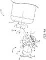
- Figure 1is a schematic showing an example of an implanted relatively compact implantable medical device 100.
- Figure 1illustrates medical device 100 having been delivered through a catheter 200, which an operator has maneuvered up through the inferior vena cava IVC and the right atrium RA into the right ventricle RV.
- Device 100is shown deployed at an implant site in the right ventricular apex. Another potential cardiac implant site may be within an appendage of a right atrium RA, or within a coronary vein.
- Device 100 and catheter 200may be similar to the device and tool, respectively, described in the commonly assigned United States Patent Application US 2015/0094668 .
- Figure 1further illustrates device 100 including a hermetically sealed enclosure 105 containing pulse generator electronics and a power source (not shown), pace/sense electrodes 111, 112 formed on an exterior surface of enclosure 105, and a fixation member, for example, formed from a plurality of elastically deformable fingers 115 mounted to a distal end of enclosure 105, in proximity to electrode 111, in order to fix, or secure electrode 111 against the endocardial surface at the implant site.
- Enclosure 105is preferably formed from a biocompatible and biostable metal such as titanium overlaid with an insulative layer, for example, medical grade polyurethane or silicone, except where electrode 112 is formed as an exposed portion of the metal.
- An hermetic feedthrough assemblycouples electrode 111 to the pulse generator contained within device enclosure 105.
- Device 100is shown fixed at the implant site by fingers 115 of the fixation member thereof, but still secured to catheter 200 by a flexible tether 280, which extends out from a distal opening 203 of catheter 200, being joined to a holding member 121 of device 100.
- tether 280extends out from a distal opening 203 of catheter 200, being joined to a holding member 121 of device 100.
- the operatorcan separate tether 280 from device 100, for example, by releasing an end of one length 281 of tether 280, and then pulling on an end of another length 282 of tether 280 to withdraw an entirety of length 282 proximally through delivery catheter 200 so that tether length 281 is pulled distally and through holding member 121.
- Securing device 100 to catheter 200 with tether 280is typically accomplished by a process in which tether 280 is looped through device holding member 121, after which first and second lengths 281, 282 of tether 280 are threaded through one or more lumens of catheter 200 such that opposing ends thereof protrude out from a proximal opening 201 of catheter 200. Because this process may be somewhat tedious, a manufacturer of device 100 and catheter 200 may secure the two together as a system, and provide the system to the operator in a single sterile package.
- the packaging of such a device separately from the associated cathetermay be preferred, so that alternative means for securing the device to the catheter may be necessary to increase the ease by which an operator may load the device into the catheter at the time of an implant procedure.
- Embodiments of interventional medical systemsinclude a relatively compact implantable medical device and a catheter, wherein a receptacle, which may be formed in a distal end of an inner assembly shaft of the catheter, has an interior contour configured to mate with a head and neck contour of a holding member of the device, and has a laterally facing opening with a profile that matches a longitudinal profile of the head and neck of the holding member.
- a receptaclewhich may be formed in a distal end of an inner assembly shaft of the catheter, has an interior contour configured to mate with a head and neck contour of a holding member of the device, and has a laterally facing opening with a profile that matches a longitudinal profile of the head and neck of the holding member.
- the catheter inner assemblyfurther includes a lock and release member useful for securing the device to the catheter, when the device holding member has been passed through the opening of the receptacle to mate with the interior contour of the receptacle.
- the lock and release memberincludes an arcuate sidewall in sliding engagement with the shaft so that the sidewall can be moved between a first location, at which the sidewall overlays the laterally facing opening of the receptacle, and a second location, at which the sidewall is located proximal to the opening.
- a handle of the catheterincludes a control member coupled to the lock and release member.
- Figure 2Ais a plan view of an interventional medical system 3400, according to some embodiments.
- Figure 2Aillustrates system 3400 including a catheter 300 and an implantable medical device 400, 500 (two types of embodiments described below), which is similar to device 100 described above, in conjunction with Figure 1 .
- Figure 2Afurther illustrates catheter 300 including an elongate outer tubular member 320, an inner assembly 350, 650 (two types of embodiments described below), and a handle 370, wherein handle 370 includes a first control member 371 coupled to outer tubular member 371, and a second control member 372 coupled to a lock and release member 50 of inner assembly 350, 650, which will be described in greater detail below.
- inner assembly 350extends within a lumen 302 ( Figure 5 ) of outer tubular member 320 and is in sliding engagement therewith, so that, when control member 371 is moved to a first position, a distal portion of inner assembly 350, 650 is contained within lumen 302, and, when control member 371 is moved to a second position, as shown in Figure 2A , inner assembly 350, 650 protrudes distally from a distal-most opening 303 of lumen 302, which is defined at a distal end 322 of outer tubular member 320.
- Figure 2Bis a schematic cross-section view through section line B-B of Figure 2A , in which proximal ends 321, 51 of outer tubular member 320 and lock and release member 50, respectively, are shown coupled to the corresponding control members 371, 372 within a shell S of handle 370.
- Handle 370may be constructed from injection molded, relatively hard, medical grade plastic parts, according to methods known in the art.
- medical device 400, 500includes a holding member 421, 521 having a contour that forms a neck N and an enlarged head H, wherein neck N extends proximally from a proximal end 12 of device housing 105.
- Figures 3A-Bare a perspective views of the distal portion of catheter inner assembly 350 and a proximal portion of medical device 400, according to some embodiments, in which device 400 is shown positioned relative to inner assembly 350, according to some methods for securing device 400 to catheter 300.
- Figures 3A-Bshow lock and release member 50 of catheter inner assembly 350 retracted, for example, by moving second control member 372 per arrow R of Figure 2A , to expose a distal end 32 of an elongate shaft 30 of inner assembly 350.
- a proximal end 31 of shaft 30is shown fixed to shell S of handle 370, such that second control member 372 may be employed to retract and advance lock and release member 50 relative to shaft 30.
- Figure 3Aillustrates distal end 32 of shaft 30 having a receptacle 34 formed therein to receive enlarged head H and neck N of device holding member 421, for example, as shown in Figure 3B .
- receptacle 34 of shaft 30has an interior contour IC3 configured to mate with the head and neck contour of device holding member 421, when holding member 421 is received therein. At least a portion of interior contour IC3 is shown being approximately hemispherical to mate with the spherical contour of holding member head H, according to some embodiments.
- Figure 3Aillustrates receptacle 34 including a laterally facing opening that has a profile LO3 matching a longitudinal profile of neck N and enlarged head H of holding member 421, wherein the longitudinal profile corresponds to that which extends parallel to a longitudinal axis D of device 400.
- a longitudinal axis C of catheter inner assembly shaft 30is shown in Figure 3A for reference, so that the descriptor "laterally facing" for the opening of receptacle 34 can be understood to mean facing in a direction approximately orthogonal to axis C.
- profile LO3 of the lateral facing opening of receptacle 34matches the head and neck profile of holding member 421 so that the opening only allows a properly oriented passage of holding member 421 therethrough, for example, per arrow P.
- receptacle 34is sized such that passage of holding member 421 through the laterally facing opening thereof and into mating contact with interior contour IC3 does not cause holding member 421 or receptacle opening to deform.
- Figure 3Billustrates a distal end of lock and release member 50 of inner assembly 350 being formed by an arcuate sidewall 52, which, in a retracted position, being located proximal to shaft distal end 32, allows passage of holding member 421 into and out from of receptacle 34.
- sidewall 52is in sliding engagement around shaft 30, to be moved, per arrow L, from the retracted position to an advanced position, at which sidewall 52 overlays the laterally facing opening of receptacle 34 to secure device 400 to catheter 300.
- outer tubular member 320may be advanced, per arrow A of Figure 2A , relative to inner assembly 350 and the secured device 400, so that the distal portion of inner assembly 350 and secured device 400 are contained within lumen 302 of outer tubular member 320, for example, as described below in conjunction with Figure 5 .
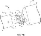
- Figures 4A-Bare perspective views of a distal portion of catheter inner assembly 650 and a proximal portion of associated implantable medical device 500, according to some alternate embodiments.
- Figures 4A-Billustrate the head and neck contour of device holding member 521 being slightly different than that of device holding member 421.
- Figures 4A-Bfurther illustrate a distal end 62 of an elongate shaft 60 of catheter inner assembly 650 exposed and having a receptacle 64 formed therein that conforms to head H and neck N of holding member 521.
- receptacle 64has an interior contour IC6 configured to mate with the head and neck contour of device holding member 521, when holding member 521 is received therein, for example, as shown in Figure 4B .
- Receptacle 64may receive device holding member 521 through one of a pair of laterally facing openings thereof, each of which has a profile LO6 matching a longitudinal profile of head H and neck N of holding member 521, the longitudinal profile extending along longitudinal axis D of device 500.
- Figure 4Ashows longitudinal axis C of catheter inner assembly 650 to provide a reference for the orientation of each of the pair of laterally facing openings of receptacle 64 (that is, facing in a direction approximately orthogonal to axis C), and to show that openings are located directly opposite one another and aligned with one another.
- profile LO6 of each laterally facing opening of receptacle 64allows only properly oriented passage of holding member 521 therethrough, for example, per arrow P of Figure 4A ; and the passage of holding member 521 into receptacle 64 does not cause either to deform.
- inner assembly 650includes lock and release member 50, which operates in the same manner described above for inner assembly 350, being retractable (per arrow R of Figure 2A ) and advanceable (per arrow L of Figure 4B ) relative to shaft 60.
- arcuate sidewall 52 of lock and release member 50may be moved per arrow L to overlay the openings of receptacle 64 and thereby secure device 500 to catheter 300.
- outer tubular member 320may be advanced, per arrow A of Figure 2A , relative to inner assembly 650 and the secured device 500, so that the distal portion of inner assembly 650 and secured device 500 are contained within lumen 302 of outer tubular member 320, as shown in Figure 5 .
- Figure 5is a longitudinal cross-section view through a distal portion of system 3400, according to any of the embodiments described above and below.
- Figure 5illustrates secured device 400, 500 having been passed through distal-most opening 303 to be contained within lumen 302 at distal end 322 of outer tubular member 320, such that outer tubular member 320 holds elastically deformable fingers 115 of the device fixation member in an extended condition.
- fingers 115which may number up to as many as eight, are formed from a super-elastic material, for example, having been cut from a Nitinol tube according to methods known in the art.
- fingers 115may be shaped by bending and holding fingers 115 in the relaxed curvature shown in Figure 2A , while heat treating, according to methods known to those skilled in the art.
- Fixation fingers 115may be mounted around electrode 111, for example, in a manner similar to that described for a fixation component 102 in a commonly assigned United States Patent Application 2012/0172690.
- the super-elastic nature of Nitinolallows fingers 115 to elastically deform between the relaxed condition of Figure 2A and the extended condition of Figure 5 , in which a free end of each finger 115 extends distally away from device housing 105.
- an operatorcan employ catheter 300 to deliver secured device 400, 500, which is contained within lumen 302 of outer tubular member 320, to a target implant site, for example, the site in the right ventricle RV shown in Figure 1 , with fixation member fingers 115 oriented to pierce into tissue at the implant site as the operator retracts outer tubular member 320 relative to inner assembly 350, 550 and secured device 400, 500, for example, by moving first control member 371 toward the second position shown in Figure 2A .
- the piercing fingers 115are configured to secure electrode 111 in intimate tissue contact at the target implant site, and, according to some embodiments, device 400, 500 preferably includes a steroid-eluting member (not shown), for example, mounted in, or around electrode 111, which is useful for reducing inflammation of the pierced tissue to maintain effective and efficient pacing via electrode 111.
- a steroid-eluting membernot shown
- the operatormay apply a pull force through catheter 300 to test the fixation of device 400, 500 at the implant site, and/or remove device 400, 500 from the implant site for repositioning at a more suitable site, if necessary.
- a lumen 33, 63 of inner assembly shaft 30, 60may extend along the entire length thereof, for example, being in fluid communication with receptacle 34, 64 at distal end 32, 62, and in fluid communication with a proximal port opening 376 of handle 370 ( Figure 2A ), for example, via a conduit shown with dashed lines in Figure 2B .
- a diameter of lumen 33, 63may range from approximately .065 inch to approximately 0.085 inch, for example, to receive passage therethrough of a goose neck snare tool, such as is known to those skilled in the art, which may be useful in retrieving the released device 400, 500 from the implant site, if necessary.
- An outer diameter of the length of shaft 30, 60may be approximately 0.11 inch, in some exemplary embodiments.
- either of inner assemblies 350, 650may include a steering subassembly, according to any suitable configuration known in the art.
- the optional steering subassemblyis shown including an elongate pull wire PW and a pull band PB, wherein pull wire PW extends along a length of shaft 30, 60 with a proximal end thereof coupled to a third control member 373 of handle 370, and a distal end thereof coupled to pull band PB, which is mounted around shaft 30, 60 in proximity to distal end 32, 62.
- Pull wire PWmay extend in another lumen of shaft 30, 60, which extends alongside lumen 33, 63 and has a diameter of approximately 0.016 inch. According to some methods, an operator moves third control member 373 to deflect inner assembly 350, 650, via pull wire PW, when navigating catheter 300 to the target implant site. According to some other exemplary embodiments, rather than being integrated into inner assembly 350, 650, a steering assembly is integrated into outer tubular member 320 in a similar fashion to that described above, according to methods known in the art.
- catheter 300is as follows.
- Outer tubular member 320for example, extending over a length of approximately 100 cm, may be formed by a stainless steel braid-reinforced medical grade polymer, for example, one or more appropriate grades of polyether block amide, which are arranged for decreasing stiffness from handle 370 to distal end 322 (e.g., including PEBAX ® 3533, 6333, 4033, and 7233), and lumen 302 of tubular member 320 may have a diameter of up to approximately 0.3 inch (7.6 mm) at distal end 322.
- a stainless steel braid-reinforced medical grade polymerfor example, one or more appropriate grades of polyether block amide, which are arranged for decreasing stiffness from handle 370 to distal end 322 (e.g., including PEBAX ® 3533, 6333, 4033, and 7233), and lumen 302 of tubular member 320 may have a diameter of up to approximately 0.3 inch (7.6 mm) at distal end 322.
- Distal end 322may have a radiopaque filler blended therein, or a radiopaque marker (e.g., Tungsten-filled Vestamid ® ) bonded thereto, either according to methods known to those skilled in the art.
- inner assembly shaft 30, 60may also have a length being formed from a stainless steel braid-reinforced medical grade polymer, for example, one or more appropriate grades of polyether block amide (e.g., including PEBAX ® 3533, 6333, 4033), wherein distal end 32, 62 may formed separately from the length, for example, also from a polyether block amide, such as PEBAX ® 7233, that is over-molded onto the length, or molded separately and heat fused to the length.
- polyether block amidee.g., including PEBAX ® 3533, 6333, 4033
- distal end 32, 62is radiopaque for fluoroscopic visualization, for example, being formed from a material that includes a radiopaque filler, such as PEBAX ® 7233 blended with 20% to 60% Barium Sulfate.
- a radiopaque fillersuch as PEBAX ® 7233 blended with 20% to 60% Barium Sulfate.
- lock and release member 50 of inner assembly 350, 650includes an elongate tube 501 joining proximal end 51 to the distal end thereof, wherein tube 501 may encompass arcuate sidewall 52 that forms the distal end.
- tube 501is relatively flexible between the proximal and distal ends, for example, being formed from a relatively soft grade of medical grade polyether block amide, such as PEBAX ® 3533 or PEBAX ® 5533, with stainless steel braid reinforcement.
- Arcuate sidewall 52 of lock and release member 50may be significantly stiffer than tube 501 and sufficient to ensure retention of device holding member 421, 521 within receptacle 34, 64, wherein sidewall 52 may be formed from a harder durometer material, such as a medical grade polyamide or the aforementioned PEBAX ® 7233 that is over-molded or heat fused to tube 501.
Landscapes
- Health & Medical Sciences (AREA)
- Cardiology (AREA)
- Heart & Thoracic Surgery (AREA)
- Life Sciences & Earth Sciences (AREA)
- Public Health (AREA)
- Biomedical Technology (AREA)
- Engineering & Computer Science (AREA)
- Animal Behavior & Ethology (AREA)
- General Health & Medical Sciences (AREA)
- Nuclear Medicine, Radiotherapy & Molecular Imaging (AREA)
- Veterinary Medicine (AREA)
- Vascular Medicine (AREA)
- Radiology & Medical Imaging (AREA)
- Surgery (AREA)
- Medical Informatics (AREA)
- Pathology (AREA)
- Molecular Biology (AREA)
- Media Introduction/Drainage Providing Device (AREA)
- Prostheses (AREA)
Description
- The present disclosure pertains to interventional medical systems that include relatively compact implantable medical devices, and more particularly to assemblies of catheters that are configured to deliver the devices to an implant site.
- The traditional implantable cardiac pacemaker includes a pulse generator device to which one or more flexible elongate lead wires are coupled. The device is typically implanted in a subcutaneous pocket, remote from the heart, and each of the one or more lead wires extends therefrom to a corresponding electrode, coupled thereto and positioned at a pacing site, either endocardial or epicardial. Mechanical and/or MRI compatibility issues, which are sometimes associated with elongate lead wires and well known to those skilled in the art, have motivated the development of implantable cardiac pacing devices that are wholly contained within a relatively compact package, the entirety of which is configured for implant in close proximity to the pacing site, for example, within a right ventricle RV of the heart.
Figure 1 is a schematic showing an example of an implanted relatively compact implantablemedical device 100.Figure 1 illustratesmedical device 100 having been delivered through acatheter 200, which an operator has maneuvered up through the inferior vena cava IVC and the right atrium RA into the right ventricle RV.Device 100 is shown deployed at an implant site in the right ventricular apex. Another potential cardiac implant site may be within an appendage of a right atrium RA, or within a coronary vein.Device 100 andcatheter 200 may be similar to the device and tool, respectively, described in the commonly assigned United States Patent ApplicationUS 2015/0094668 .Figure 1 further illustratesdevice 100 including a hermetically sealedenclosure 105 containing pulse generator electronics and a power source (not shown), pace/sense electrodes enclosure 105, and a fixation member, for example, formed from a plurality of elasticallydeformable fingers 115 mounted to a distal end ofenclosure 105, in proximity toelectrode 111, in order to fix, or secureelectrode 111 against the endocardial surface at the implant site.Enclosure 105 is preferably formed from a biocompatible and biostable metal such as titanium overlaid with an insulative layer, for example, medical grade polyurethane or silicone, except whereelectrode 112 is formed as an exposed portion of the metal. An hermetic feedthrough assembly, such as any suitable type known to those skilled in the art,couples electrode 111 to the pulse generator contained withindevice enclosure 105.Device 100 is shown fixed at the implant site byfingers 115 of the fixation member thereof, but still secured tocatheter 200 by aflexible tether 280, which extends out from adistal opening 203 ofcatheter 200, being joined to aholding member 121 ofdevice 100. Thus, the operator, viatether 280, is able to test the fixation ofdevice 100 at the implant site, and/or removedevice 100 from the implant site for repositioning at a more suitable site, if necessary. Once satisfied with the implant ofdevice 100, the operator can separatetether 280 fromdevice 100, for example, by releasing an end of onelength 281 oftether 280, and then pulling on an end of anotherlength 282 oftether 280 to withdraw an entirety oflength 282 proximally throughdelivery catheter 200 so thattether length 281 is pulled distally and throughholding member 121.- Securing
device 100 tocatheter 200 withtether 280 is typically accomplished by a process in whichtether 280 is looped throughdevice holding member 121, after which first andsecond lengths tether 280 are threaded through one or more lumens ofcatheter 200 such that opposing ends thereof protrude out from aproximal opening 201 ofcatheter 200. Because this process may be somewhat tedious, a manufacturer ofdevice 100 andcatheter 200 may secure the two together as a system, and provide the system to the operator in a single sterile package. However, due to shelf life considerations, the packaging of such a device separately from the associated catheter may be preferred, so that alternative means for securing the device to the catheter may be necessary to increase the ease by which an operator may load the device into the catheter at the time of an implant procedure. - The invention is defined in claim 7. Embodiments of interventional medical systems, disclosed herein, include a relatively compact implantable medical device and a catheter, wherein a receptacle, which may be formed in a distal end of an inner assembly shaft of the catheter, has an interior contour configured to mate with a head and neck contour of a holding member of the device, and has a laterally facing opening with a profile that matches a longitudinal profile of the head and neck of the holding member. Thus, the laterally facing opening of the receptacle allows only properly oriented passage of the device holding member therethrough, and this passage is without deformation of either the device holding member or the laterally facing opening. The catheter inner assembly further includes a lock and release member useful for securing the device to the catheter, when the device holding member has been passed through the opening of the receptacle to mate with the interior contour of the receptacle. According to some embodiments of the catheter inner assembly, the lock and release member includes an arcuate sidewall in sliding engagement with the shaft so that the sidewall can be moved between a first location, at which the sidewall overlays the laterally facing opening of the receptacle, and a second location, at which the sidewall is located proximal to the opening. In some embodiments, a handle of the catheter includes a control member coupled to the lock and release member.
- The following drawings are illustrative of particular embodiments of the present disclosure and therefore do not limit the scope of the invention as claimed. The drawings are not to scale (unless so stated) and are intended for use in conjunction with the explanations in the following detailed description. Embodiments will hereinafter be described in conjunction with the appended drawings wherein like numerals denote like elements, and:
Figure 1 is a schematic showing an exemplary relatively compact implantable medical device having been delivered from a catheter to an implant site;Figure 2A is a plan view of an interventional medical system, according to some embodiments;Figure 2B is a schematic cross-section view through section line B-B ofFigure 2A ;Figures 3A-B are a perspective views of a distal portion of a catheter assembly and a proximal portion of an associated implantable medical device, according to some embodiments;Figures 4A-B are perspective views of a distal portion of a catheter assembly and a proximal portion of an associated implantable medical device, according to some alternate embodiments; andFigure 5 is a longitudinal cross-section view through a distal portion of a system, according to any of the embodiments described above.- The following detailed description is exemplary in nature and is not intended to limit the scope, applicability, or configuration of the invention as claimed in any way. Rather, the following description provides practical examples, and those skilled in the art will recognize that some of the examples may have suitable alternatives.
Figure 2A is a plan view of an interventionalmedical system 3400, according to some embodiments.Figure 2A illustratessystem 3400 including acatheter 300 and an implantablemedical device 400, 500 (two types of embodiments described below), which is similar todevice 100 described above, in conjunction withFigure 1 .Figure 2A further illustratescatheter 300 including an elongate outertubular member 320, aninner assembly 350, 650 (two types of embodiments described below), and ahandle 370, whereinhandle 370 includes afirst control member 371 coupled to outertubular member 371, and asecond control member 372 coupled to a lock andrelease member 50 ofinner assembly inner assembly 350 extends within a lumen 302 (Figure 5 ) of outertubular member 320 and is in sliding engagement therewith, so that, whencontrol member 371 is moved to a first position, a distal portion ofinner assembly lumen 302, and, whencontrol member 371 is moved to a second position, as shown inFigure 2A ,inner assembly distal-most opening 303 oflumen 302, which is defined at adistal end 322 of outertubular member 320.Figure 2B is a schematic cross-section view through section line B-B ofFigure 2A , in whichproximal ends tubular member 320 and lock andrelease member 50, respectively, are shown coupled to thecorresponding control members handle 370.Handle 370 may be constructed from injection molded, relatively hard, medical grade plastic parts, according to methods known in the art.- With further reference to
Figure 2A ,medical device holding member proximal end 12 ofdevice housing 105.Figures 3A-B are a perspective views of the distal portion of catheterinner assembly 350 and a proximal portion ofmedical device 400, according to some embodiments, in whichdevice 400 is shown positioned relative toinner assembly 350, according to some methods for securingdevice 400 tocatheter 300.Figures 3A-B show lock and releasemember 50 of catheterinner assembly 350 retracted, for example, by movingsecond control member 372 per arrow R ofFigure 2A , to expose adistal end 32 of anelongate shaft 30 ofinner assembly 350. With reference toFigure 2B , a proximal end 31 ofshaft 30 is shown fixed to shell S ofhandle 370, such thatsecond control member 372 may be employed to retract and advance lock and releasemember 50 relative toshaft 30.Figure 3A illustratesdistal end 32 ofshaft 30 having areceptacle 34 formed therein to receive enlarged head H and neck N ofdevice holding member 421, for example, as shown inFigure 3B . - With further reference to
Figure 3A ,receptacle 34 ofshaft 30 has an interior contour IC3 configured to mate with the head and neck contour ofdevice holding member 421, when holdingmember 421 is received therein. At least a portion of interior contour IC3 is shown being approximately hemispherical to mate with the spherical contour of holding member head H, according to some embodiments.Figure 3A illustratesreceptacle 34 including a laterally facing opening that has a profile LO3 matching a longitudinal profile of neck N and enlarged head H ofholding member 421, wherein the longitudinal profile corresponds to that which extends parallel to a longitudinal axis D ofdevice 400. A longitudinal axis C of catheterinner assembly shaft 30 is shown inFigure 3A for reference, so that the descriptor "laterally facing" for the opening ofreceptacle 34 can be understood to mean facing in a direction approximately orthogonal to axis C. According to the illustrated embodiment, profile LO3 of the lateral facing opening ofreceptacle 34 matches the head and neck profile ofholding member 421 so that the opening only allows a properly oriented passage ofholding member 421 therethrough, for example, per arrow P. Furthermore,receptacle 34 is sized such that passage ofholding member 421 through the laterally facing opening thereof and into mating contact with interior contour IC3 does not cause holdingmember 421 or receptacle opening to deform. Figure 3B illustrates a distal end of lock andrelease member 50 ofinner assembly 350 being formed by anarcuate sidewall 52, which, in a retracted position, being located proximal to shaftdistal end 32, allows passage of holdingmember 421 into and out from ofreceptacle 34. According to the illustrated embodiment,sidewall 52 is in sliding engagement aroundshaft 30, to be moved, per arrow L, from the retracted position to an advanced position, at whichsidewall 52 overlays the laterally facing opening ofreceptacle 34 to securedevice 400 tocatheter 300. According to some methods, after securingdevice 400 in this manner, outertubular member 320 may be advanced, per arrow A ofFigure 2A , relative toinner assembly 350 and the secureddevice 400, so that the distal portion ofinner assembly 350 and secureddevice 400 are contained withinlumen 302 of outertubular member 320, for example, as described below in conjunction withFigure 5 .Figures 4A-B are perspective views of a distal portion of catheterinner assembly 650 and a proximal portion of associated implantablemedical device 500, according to some alternate embodiments.Figures 4A-B illustrate the head and neck contour ofdevice holding member 521 being slightly different than that ofdevice holding member 421.Figures 4A-B further illustrate adistal end 62 of anelongate shaft 60 of catheterinner assembly 650 exposed and having areceptacle 64 formed therein that conforms to head H and neck N ofholding member 521. With reference toFigure 4A ,receptacle 64 has an interior contour IC6 configured to mate with the head and neck contour ofdevice holding member 521, when holdingmember 521 is received therein, for example, as shown inFigure 4B .Receptacle 64 may receivedevice holding member 521 through one of a pair of laterally facing openings thereof, each of which has a profile LO6 matching a longitudinal profile of head H and neck N ofholding member 521, the longitudinal profile extending along longitudinal axis D ofdevice 500. As inFigure 3A ,Figure 4A shows longitudinal axis C of catheterinner assembly 650 to provide a reference for the orientation of each of the pair of laterally facing openings of receptacle 64 (that is, facing in a direction approximately orthogonal to axis C), and to show that openings are located directly opposite one another and aligned with one another.- According to the illustrated embodiment, profile LO6 of each laterally facing opening of
receptacle 64 allows only properly oriented passage ofholding member 521 therethrough, for example, per arrow P ofFigure 4A ; and the passage ofholding member 521 intoreceptacle 64 does not cause either to deform. With reference toFigure 4B , in conjunction withFigures 2A-B ,inner assembly 650 includes lock andrelease member 50, which operates in the same manner described above forinner assembly 350, being retractable (per arrow R ofFigure 2A ) and advanceable (per arrow L ofFigure 4B ) relative toshaft 60. Thus, after holdingmember 521 has been passed through one of the pair of laterally facing openings ofreceptacle 64, so that the head and neck contour of holdingmember 521 mates with interior contour IC6, as shown inFigure 4B ,arcuate sidewall 52 of lock andrelease member 50 may be moved per arrow L to overlay the openings ofreceptacle 64 and therebysecure device 500 tocatheter 300. As was described above fordevice 400, oncedevice 500 is secured, outertubular member 320 may be advanced, per arrow A ofFigure 2A , relative toinner assembly 650 and thesecured device 500, so that the distal portion ofinner assembly 650 andsecured device 500 are contained withinlumen 302 of outertubular member 320, as shown inFigure 5 . Figure 5 is a longitudinal cross-section view through a distal portion ofsystem 3400, according to any of the embodiments described above and below.Figure 5 illustratessecured device distal-most opening 303 to be contained withinlumen 302 atdistal end 322 of outertubular member 320, such that outertubular member 320 holds elasticallydeformable fingers 115 of the device fixation member in an extended condition. According to an exemplary embodiment,fingers 115, which may number up to as many as eight, are formed from a super-elastic material, for example, having been cut from a Nitinol tube according to methods known in the art. After cutting the Nitinol tubing,fingers 115 may be shaped by bending and holdingfingers 115 in the relaxed curvature shown inFigure 2A , while heat treating, according to methods known to those skilled in the art.Fixation fingers 115 may be mounted aroundelectrode 111, for example, in a manner similar to that described for a fixation component 102 in a commonly assigned United States Patent Application 2012/0172690. The super-elastic nature of Nitinol allowsfingers 115 to elastically deform between the relaxed condition ofFigure 2A and the extended condition ofFigure 5 , in which a free end of eachfinger 115 extends distally away fromdevice housing 105. Thus, an operator can employcatheter 300 to deliversecured device lumen 302 of outertubular member 320, to a target implant site, for example, the site in the right ventricle RV shown inFigure 1 , withfixation member fingers 115 oriented to pierce into tissue at the implant site as the operator retracts outertubular member 320 relative toinner assembly 350, 550 andsecured device first control member 371 toward the second position shown inFigure 2A .- The piercing
fingers 115 are configured to secureelectrode 111 in intimate tissue contact at the target implant site, and, according to some embodiments,device electrode 111, which is useful for reducing inflammation of the pierced tissue to maintain effective and efficient pacing viaelectrode 111. Once the operator deploysdevice fixation member fingers 115 securing electrode to tissue at the implant site, the operator may apply a pull force throughcatheter 300 to test the fixation ofdevice device Figures 3A-B andFigures 4A-B , it may be appreciated that such a force, represented by arrow F (Figures 3B ,4B ), is transferred todevice member receptacle release member 50 ofinner assembly arcuate sidewall 52 at the distal end thereof no longer covers the laterally facing opening(s) ofreceptacle device catheter 300 by allowingdevice holding member receptacle - With reference back to
Figures 3A and4A , alumen inner assembly shaft receptacle distal end proximal port opening 376 of handle 370 (Figure 2A ), for example, via a conduit shown with dashed lines inFigure 2B . A diameter oflumen device shaft - Furthermore, in some exemplary embodiments, either of
inner assemblies Figures 2A-B ,Figure 3A , andFigure 4A , the optional steering subassembly is shown including an elongate pull wire PW and a pull band PB, wherein pull wire PW extends along a length ofshaft third control member 373 ofhandle 370, and a distal end thereof coupled to pull band PB, which is mounted aroundshaft distal end shaft lumen third control member 373 to deflectinner assembly catheter 300 to the target implant site. According to some other exemplary embodiments, rather than being integrated intoinner assembly tubular member 320 in a similar fashion to that described above, according to methods known in the art. - Finally some additional construction detail, according to some exemplary embodiments of
catheter 300, is as follows. - Outer
tubular member 320, for example, extending over a length of approximately 100 cm, may be formed by a stainless steel braid-reinforced medical grade polymer, for example, one or more appropriate grades of polyether block amide, which are arranged for decreasing stiffness fromhandle 370 to distal end 322 (e.g., including PEBAX® 3533, 6333, 4033, and 7233), andlumen 302 oftubular member 320 may have a diameter of up to approximately 0.3 inch (7.6 mm) atdistal end 322.Distal end 322 may have a radiopaque filler blended therein, or a radiopaque marker (e.g., Tungsten-filled Vestamid®) bonded thereto, either according to methods known to those skilled in the art. In these exemplary embodiments,inner assembly shaft distal end distal end - With reference to
Figure 5 , lock andrelease member 50 ofinner assembly elongate tube 501 joiningproximal end 51 to the distal end thereof, whereintube 501 may encompassarcuate sidewall 52 that forms the distal end. According to some preferred embodiments,tube 501 is relatively flexible between the proximal and distal ends, for example, being formed from a relatively soft grade of medical grade polyether block amide, such as PEBAX® 3533 or PEBAX® 5533, with stainless steel braid reinforcement.Arcuate sidewall 52 of lock andrelease member 50 may be significantly stiffer thantube 501 and sufficient to ensure retention ofdevice holding member receptacle sidewall 52 may be formed from a harder durometer material, such as a medical grade polyamide or the aforementioned PEBAX® 7233 that is over-molded or heat fused totube 501. - In the foregoing detailed description, the methods and assemblies have been described with reference to specific embodiments. However, it may be appreciated that various modifications and changes can be made without departing from the scope of the invention as set forth in the appended claims.
Claims (9)
- An interventional medical system comprising a relatively compact implantable medical device (400) and a catheter (300); the medical device comprising an electronic controller, a hermetically sealed housing containing the controller, an electrode electrically coupled to the controller, a fixation member mounted to a distal end of the housing, and a holding member, the holding member having a first contour, wherein the first contour forms a neck and an enlarged head, the neck extending longitudinally from a proximal end of the housing to the head; the catheter comprising an elongate inner assembly (350), an elongate outer tubular member (320), and a handle (370), the handle comprising a first control member (371) and a second control member (372), the outer tubular member comprising a proximal end (321) coupled to the first control member, the outer tubular member defining an elongate lumen (302) that extends from a proximal opening thereof, at the proximal end of the tubular member, to a distal-most opening thereof, at a distal end of the outer tubular member, the distal-most opening allowing passage of the medical device therethrough, the inner assembly extending along, and being in sliding engagement within the lumen of the outer tubular member; and the catheter inner assembly comprising:an elongate shaft (30) including a proximal end (31) secured to the handle, and a distal end (32) having a receptacle (34) formed therein, the receptacle being sized to receive the device holding member and having an interior contour configured to mate with the contour of the device holding member when the holding member is received therein, and the receptacle including a laterally facing opening, the laterally facing opening having a profile that matches a longitudinal profile of the neck and the enlarged head of the first contour of the device holding member so that the laterally facing opening allows only a properly oriented passage of the holding member therethrough, the passage being without deformation of either the device holding member or the laterally facing opening of the receptacle; anda lock and release member (50) extending alongside the elongate shaft, the lock and release member including a proximal end and a distal end, the proximal end of the lock and release member being coupled to the second control member of the handle, and the distal end comprising an arcuate sidewall (52) in sliding engagement around the shaft; andwherein, when the second control member of the catheter handle is in a first position, the arcuate sidewall of the distal end of the lock and release member overlays the laterally facing opening of the shaft receptacle;when the second control member of the catheter handle is in a second position, the arcuate sidewall of the distal end of the lock and release member is located proximal to the laterally facing opening of the shaft receptacle;when the first control member of the catheter handle is in a first position, the distal end of the shaft and the lock and release member of the inner assembly is contained within the lumen of the outer tubular member of the catheter; andwhen the first control member of the catheter handle is in a second position, the inner assembly protrudes distally from the distal-most opening of the lumen of the outer tubular member of the catheter.
- The system of claim 1, wherein the handle of the catheter further comprises a third control member (373); and the inner assembly of the catheter further comprises a steering subassembly, the steering subassembly comprising an elongate pull wire (PW) and a pull band (PB), the pull wire extending along a length of the shaft and including a proximal end coupled to the third control member of the handle and distal end coupled to the pull band, the pull band being mounted around the shaft just proximal to the distal end thereof.
- The system of any one of claims 1-2, wherein the laterally facing opening of the receptacle of the inner assembly shaft is a first opening of a pair of laterally facing openings; and a second opening of the pair is located directly opposite the first opening, being aligned therewith, the second opening having a profile that is identical to that of the first opening.
- The system of any one of claims 1-3, wherein at least a portion of the contour of receptacle of the inner assembly shaft is approximately hemispherical.
- The system of any one of claims 1-4, wherein the distal end of the inner assembly shaft is radiopaque.
- The system of any one of claims 1-5, wherein inner assembly lock and release member further includes an elongate tube (501) joining the proximal end thereof to the distal end thereof, the tube extending around the inner assembly shaft, and the arcuate sidewall of the distal end being significantly stiffer than the tube.
- A catheter assembly useful for securing an implantable medical device (400) to the catheter (300), the device comprising an electronic controller, a hermetically sealed housing containing the controller, and a holding member, the holding member having a first contour, wherein the first contour forms a neck and an enlarged head, the neck extending longitudinally from a proximal end of the housing to the head, and the assembly comprising:a handle (370) comprising a control member (371);an elongate shaft (30) including a proximal end (31) secured to the handle, and a distal end (32) having a receptacle (34) formed therein, the receptacle being sized to receive the device holding member and having an interior contour configured to mate with the contour of the device holding member when the holding member is receive therein, and the receptacle including a laterally facing opening, the laterally facing opening having a profile that matches a longitudinal profile of the neck and the enlarged head of the first contour of the device holding member so that the laterally facing opening allows only a properly oriented passage of the holding member therethrough, the passage being without deformation of either the device holding member or the laterally facing opening of the distal end receptacle; anda lock and release member (50) extending alongside the elongate shaft, the lock and release member including a proximal end and a distal end, the proximal end of the lock and release member being coupled to the control member of the handle, and the distal end comprising an arcuate sidewall (52) in sliding engagement around the shaft; andwherein, when the control member of the handle is in a first position, the arcuate sidewall of the distal end of the lock and release member overlays the laterally facing opening of the shaft receptacle; andwhen the control member of the handle is in a second position, the arcuate sidewall of the distal end of the lock and release member is located proximal to the laterally facing opening of the shaft receptacle.
- The assembly of claim 7, wherein the laterally facing opening of the shaft receptacle is a first opening of a pair of laterally facing openings; and a second opening of the pair is located directly opposite the first opening, being aligned therewith, the second opening having a profile that is identical to that of the first opening.
- The assembly of any one of claims 7-8, wherein the lock and release member further includes an elongate tube (501) joining the proximal end thereof to the distal end thereof, the tube extending around the shaft, and the arcuate sidewall of the distal end being significantly stiffer than the tube.
Applications Claiming Priority (2)
| Application Number | Priority Date | Filing Date | Title |
|---|---|---|---|
| US15/140,565US10350408B2 (en) | 2016-04-28 | 2016-04-28 | Interventional medical systems, associated assemblies and methods |
| PCT/US2017/029822WO2017189838A2 (en) | 2016-04-28 | 2017-04-27 | Interventional medical systems, associated assemblies and methods |
Publications (2)
| Publication Number | Publication Date |
|---|---|
| EP3448490A2 EP3448490A2 (en) | 2019-03-06 |
| EP3448490B1true EP3448490B1 (en) | 2022-08-24 |
Family
ID=58672797
Family Applications (1)
| Application Number | Title | Priority Date | Filing Date |
|---|---|---|---|
| EP17722328.6AActiveEP3448490B1 (en) | 2016-04-28 | 2017-04-27 | Interventional medical systems and associated assemblies |
Country Status (4)
| Country | Link |
|---|---|
| US (1) | US10350408B2 (en) |
| EP (1) | EP3448490B1 (en) |
| CN (1) | CN109152909B (en) |
| WO (1) | WO2017189838A2 (en) |
Families Citing this family (18)
| Publication number | Priority date | Publication date | Assignee | Title |
|---|---|---|---|---|
| US11198013B2 (en) | 2016-11-21 | 2021-12-14 | Cardiac Pacemakers, Inc. | Catheter and leadless cardiac devices including electrical pathway barrier |
| WO2018094193A1 (en) | 2016-11-21 | 2018-05-24 | Cardiac Pacemakers, Inc. | Delivery devices and wall apposition sensing |
| US10485981B2 (en) | 2016-12-27 | 2019-11-26 | Cardiac Pacemakers, Inc. | Fixation methods for leadless cardiac devices |
| CN110114114B (en) | 2016-12-27 | 2023-05-02 | 心脏起搏器股份公司 | Delivery devices and methods for leadless cardiac devices |
| US10806931B2 (en) | 2016-12-27 | 2020-10-20 | Cardiac Pacemakers, Inc. | Delivery devices and methods for leadless cardiac devices |
| AU2017387024B2 (en) | 2016-12-27 | 2020-04-09 | Cardiac Pacemakers, Inc. | Leadless delivery catheter with conductive pathway |
| WO2018140597A2 (en) | 2017-01-26 | 2018-08-02 | Cardiac Pacemakers, Inc. | Delivery devices and methods for leadless cardiac devices |
| CN110418661B (en) | 2017-03-10 | 2024-01-02 | 心脏起搏器股份公司 | Fixing piece for leadless cardiac device |
| US10737092B2 (en) | 2017-03-30 | 2020-08-11 | Cardiac Pacemakers, Inc. | Delivery devices and methods for leadless cardiac devices |
| WO2018236958A1 (en)* | 2017-06-22 | 2018-12-27 | St. Jude Medical, Cardiology Division, Inc. | ADMINISTRATION DEVICE WITH ATTACHMENT FOR IMPLANTABLE MEDICAL DEVICE |
| US11577085B2 (en) | 2017-08-03 | 2023-02-14 | Cardiac Pacemakers, Inc. | Delivery devices and methods for leadless cardiac devices |
| CN113660977B (en) | 2019-03-29 | 2024-12-17 | 心脏起搏器股份公司 | Systems and methods for treating cardiac arrhythmias |
| EP3946556B1 (en) | 2019-03-29 | 2024-06-19 | Cardiac Pacemakers, Inc. | Systems for treating cardiac arrhythmias |
| US11510697B2 (en) | 2019-09-11 | 2022-11-29 | Cardiac Pacemakers, Inc. | Tools and systems for implanting and/or retrieving a leadless cardiac pacing device with helix fixation |
| WO2021050685A1 (en) | 2019-09-11 | 2021-03-18 | Cardiac Pacemakers, Inc. | Tools and systems for implanting and/or retrieving a leadless cardiac pacing device with helix fixation |
| US20240058616A1 (en)* | 2022-08-17 | 2024-02-22 | Pacesetter, Inc. | Biostimulator transport system having drive belt |
| US12397459B2 (en) | 2023-05-17 | 2025-08-26 | Pacesetter, Inc. | Systems and methods for a slitter assembly |
| WO2024236438A1 (en)* | 2023-05-17 | 2024-11-21 | Medtronic, Inc. | Retainer for a medical device delivery system |
Citations (1)
| Publication number | Priority date | Publication date | Assignee | Title |
|---|---|---|---|---|
| US5417708A (en)* | 1994-03-09 | 1995-05-23 | Cook Incorporated | Intravascular treatment system and percutaneous release mechanism therefor |
Family Cites Families (36)
| Publication number | Priority date | Publication date | Assignee | Title |
|---|---|---|---|---|
| US3835864A (en) | 1970-09-21 | 1974-09-17 | Rasor Ass Inc | Intra-cardiac stimulator |
| US4280510A (en)* | 1979-02-08 | 1981-07-28 | Medtronic, Inc. | Sutureless myocardial lead introducer |
| US4411276A (en)* | 1981-04-28 | 1983-10-25 | Medtronic, Inc. | Implantable multiple connector |
| US5180368A (en)* | 1989-09-08 | 1993-01-19 | Advanced Cardiovascular Systems, Inc. | Rapidly exchangeable and expandable cage catheter for repairing damaged blood vessels |
| US5261916A (en) | 1991-12-12 | 1993-11-16 | Target Therapeutics | Detachable pusher-vasoocclusive coil assembly with interlocking ball and keyway coupling |
| US5250071A (en) | 1992-09-22 | 1993-10-05 | Target Therapeutics, Inc. | Detachable embolic coil assembly using interlocking clasps and method of use |
| US5383913A (en)* | 1993-04-21 | 1995-01-24 | Schiff; Steven M. | Bidirectional lead connector for left or right sided implantation of pacemakers and/or other implantable electrophysiologic devices and a method for using the same |
| US7052493B2 (en)* | 1996-10-22 | 2006-05-30 | Epicor Medical, Inc. | Methods and devices for ablation |
| CA2643221A1 (en)* | 2002-03-15 | 2003-09-25 | Nmt Medical, Inc. | Coupling system useful in placement of implants |
| US20050267555A1 (en) | 2004-05-28 | 2005-12-01 | Marnfeldt Goran N | Engagement tool for implantable medical devices |
| JP2011521697A (en)* | 2008-05-30 | 2011-07-28 | コーニンクレッカ フィリップス エレクトロニクス エヌ ヴィ | Implantable connection device |
| AU2010236349B2 (en)* | 2009-04-15 | 2015-04-02 | Microvention, Inc. | Implant delivery system |
| EP2394695B1 (en) | 2010-06-14 | 2012-09-26 | Sorin CRM SAS | Standalone intracardiac capsule and implantation accessory |
| US20120095539A1 (en) | 2010-10-13 | 2012-04-19 | Alexander Khairkhahan | Delivery Catheter Systems and Methods |
| US8615310B2 (en) | 2010-12-13 | 2013-12-24 | Pacesetter, Inc. | Delivery catheter systems and methods |
| US9775982B2 (en) | 2010-12-29 | 2017-10-03 | Medtronic, Inc. | Implantable medical device fixation |
| US20120172891A1 (en) | 2010-12-29 | 2012-07-05 | Medtronic, Inc. | Implantable medical device fixation testing |
| US8758365B2 (en)* | 2011-08-03 | 2014-06-24 | Medtronic, Inc. | Implant system including guiding accessory and methods of use |
| US8504156B2 (en) | 2011-08-26 | 2013-08-06 | Medtronic, Inc. | Holding members for implantable cardiac stimulation devices |
| US8945145B2 (en) | 2011-09-22 | 2015-02-03 | Medtronic, Inc. | Delivery system assemblies for implantable medical devices |
| US8945146B2 (en) | 2011-10-24 | 2015-02-03 | Medtronic, Inc. | Delivery system assemblies and associated methods for implantable medical devices |
| US8781605B2 (en) | 2011-10-31 | 2014-07-15 | Pacesetter, Inc. | Unitary dual-chamber leadless intra-cardiac medical device and method of implanting same |
| US8721587B2 (en) | 2011-11-17 | 2014-05-13 | Medtronic, Inc. | Delivery system assemblies and associated methods for implantable medical devices |
| US9216293B2 (en) | 2011-11-17 | 2015-12-22 | Medtronic, Inc. | Delivery system assemblies for implantable medical devices |
| US20140018818A1 (en) | 2012-07-12 | 2014-01-16 | Pacesetter, Inc. | System and method of implanting a medical device |
| US9238145B2 (en) | 2012-11-27 | 2016-01-19 | Biotronik Se & Co. Kg | Leadless implantable device delivery apparatus |
| US20140172034A1 (en) | 2012-12-18 | 2014-06-19 | Pacesetter, Inc. | Intra-cardiac implantable medical device with ic device extension for lv pacing/sensing |
| KR20150140760A (en)* | 2013-04-08 | 2015-12-16 | 아파마 메디칼, 인크. | Cardiac ablation catheters and methods of use thereof |
| EP2801341A1 (en) | 2013-05-06 | 2014-11-12 | Biotronik AG | Release device for releasing a medical implant from an insertion device, and also insertion device comprising a release device |
| JP6151452B2 (en) | 2013-08-16 | 2017-06-21 | カーディアック ペースメイカーズ, インコーポレイテッド | Delivery device and method for a leadless heart device |
| US10722723B2 (en) | 2013-08-16 | 2020-07-28 | Cardiac Pacemakers, Inc. | Delivery devices and methods for leadless cardiac devices |
| JP6182675B2 (en) | 2013-08-16 | 2017-08-16 | カーディアック ペースメイカーズ, インコーポレイテッド | Leadless cardiac pacemaker and collection device |
| US9526522B2 (en)* | 2013-09-27 | 2016-12-27 | Medtronic, Inc. | Interventional medical systems, tools, and assemblies |
| US9283382B2 (en) | 2014-04-01 | 2016-03-15 | Medtronic, Inc. | Interventional medical systems, tools, and associated methods |
| US9539423B2 (en)* | 2014-07-17 | 2017-01-10 | Medtronic, Inc. | Interventional medical systems, tools, and methods of use |
| US10478620B2 (en) | 2014-08-26 | 2019-11-19 | Medtronic, Inc. | Interventional medical systems, devices, and methods of use |
- 2016
- 2016-04-28USUS15/140,565patent/US10350408B2/enactiveActive
- 2017
- 2017-04-27CNCN201780026409.2Apatent/CN109152909B/enactiveActive
- 2017-04-27WOPCT/US2017/029822patent/WO2017189838A2/ennot_activeCeased
- 2017-04-27EPEP17722328.6Apatent/EP3448490B1/enactiveActive
Patent Citations (1)
| Publication number | Priority date | Publication date | Assignee | Title |
|---|---|---|---|---|
| US5417708A (en)* | 1994-03-09 | 1995-05-23 | Cook Incorporated | Intravascular treatment system and percutaneous release mechanism therefor |
Also Published As
| Publication number | Publication date |
|---|---|
| EP3448490A2 (en) | 2019-03-06 |
| CN109152909B (en) | 2020-12-15 |
| WO2017189838A2 (en) | 2017-11-02 |
| WO2017189838A3 (en) | 2017-12-07 |
| US10350408B2 (en) | 2019-07-16 |
| CN109152909A (en) | 2019-01-04 |
| US20170312496A1 (en) | 2017-11-02 |
Similar Documents
| Publication | Publication Date | Title |
|---|---|---|
| EP3448490B1 (en) | Interventional medical systems and associated assemblies | |
| US20250177736A1 (en) | Interventional medical device and method of use | |
| US9844664B2 (en) | Interventional medical systems, catheters, and subassemblies | |
| US10434283B2 (en) | Interventional medical systems, associated assemblies and methods | |
| EP3193998B1 (en) | Interventional medical systems | |
| US9750931B2 (en) | Interventional medical systems, assemblies and methods | |
| EP3448510B1 (en) | Interventional medical systems and improved assemblies thereof and associated methods of use | |
| US20170043158A1 (en) | Interventional medical systems and catheters | |
| CN107847750B (en) | Interventional medical systems, catheters and methods | |
| EP2780077B1 (en) | Delivery system assemblies for implantable medical devices | |
| US11357484B2 (en) | Medical device retrieval with multiple snares | |
| US20160059002A1 (en) | Interventional medical systems, devices, and components thereof | |
| US20170340316A1 (en) | Interventional medical device retrieval | |
| US20250186786A1 (en) | Dual chamber pacing | |
| US20110071609A1 (en) | Biasing and fixation features on leads | |
| WO2018080470A1 (en) | Interventional medical systems and catheters | |
| US10398892B2 (en) | Interventional medical systems and associated assemblies and methods |
Legal Events
| Date | Code | Title | Description |
|---|---|---|---|
| STAA | Information on the status of an ep patent application or granted ep patent | Free format text:STATUS: UNKNOWN | |
| STAA | Information on the status of an ep patent application or granted ep patent | Free format text:STATUS: THE INTERNATIONAL PUBLICATION HAS BEEN MADE | |
| PUAI | Public reference made under article 153(3) epc to a published international application that has entered the european phase | Free format text:ORIGINAL CODE: 0009012 | |
| STAA | Information on the status of an ep patent application or granted ep patent | Free format text:STATUS: REQUEST FOR EXAMINATION WAS MADE | |
| 17P | Request for examination filed | Effective date:20181108 | |
| AK | Designated contracting states | Kind code of ref document:A2 Designated state(s):AL AT BE BG CH CY CZ DE DK EE ES FI FR GB GR HR HU IE IS IT LI LT LU LV MC MK MT NL NO PL PT RO RS SE SI SK SM TR | |
| AX | Request for extension of the european patent | Extension state:BA ME | |
| DAV | Request for validation of the european patent (deleted) | ||
| DAX | Request for extension of the european patent (deleted) | ||
| STAA | Information on the status of an ep patent application or granted ep patent | Free format text:STATUS: EXAMINATION IS IN PROGRESS | |
| 17Q | First examination report despatched | Effective date:20191010 | |
| GRAP | Despatch of communication of intention to grant a patent | Free format text:ORIGINAL CODE: EPIDOSNIGR1 | |
| STAA | Information on the status of an ep patent application or granted ep patent | Free format text:STATUS: GRANT OF PATENT IS INTENDED | |
| INTG | Intention to grant announced | Effective date:20220408 | |
| GRAS | Grant fee paid | Free format text:ORIGINAL CODE: EPIDOSNIGR3 | |
| GRAA | (expected) grant | Free format text:ORIGINAL CODE: 0009210 | |
| STAA | Information on the status of an ep patent application or granted ep patent | Free format text:STATUS: THE PATENT HAS BEEN GRANTED | |
| AK | Designated contracting states | Kind code of ref document:B1 Designated state(s):AL AT BE BG CH CY CZ DE DK EE ES FI FR GB GR HR HU IE IS IT LI LT LU LV MC MK MT NL NO PL PT RO RS SE SI SK SM TR | |
| REG | Reference to a national code | Ref country code:CH Ref legal event code:EP | |
| REG | Reference to a national code | Ref country code:IE Ref legal event code:FG4D | |
| REG | Reference to a national code | Ref country code:AT Ref legal event code:REF Ref document number:1513217 Country of ref document:AT Kind code of ref document:T Effective date:20220915 Ref country code:DE Ref legal event code:R096 Ref document number:602017060977 Country of ref document:DE | |
| REG | Reference to a national code | Ref country code:LT Ref legal event code:MG9D | |
| REG | Reference to a national code | Ref country code:NL Ref legal event code:MP Effective date:20220824 | |
| PG25 | Lapsed in a contracting state [announced via postgrant information from national office to epo] | Ref country code:SE Free format text:LAPSE BECAUSE OF FAILURE TO SUBMIT A TRANSLATION OF THE DESCRIPTION OR TO PAY THE FEE WITHIN THE PRESCRIBED TIME-LIMIT Effective date:20220824 Ref country code:RS Free format text:LAPSE BECAUSE OF FAILURE TO SUBMIT A TRANSLATION OF THE DESCRIPTION OR TO PAY THE FEE WITHIN THE PRESCRIBED TIME-LIMIT Effective date:20220824 Ref country code:PT Free format text:LAPSE BECAUSE OF FAILURE TO SUBMIT A TRANSLATION OF THE DESCRIPTION OR TO PAY THE FEE WITHIN THE PRESCRIBED TIME-LIMIT Effective date:20221226 Ref country code:NO Free format text:LAPSE BECAUSE OF FAILURE TO SUBMIT A TRANSLATION OF THE DESCRIPTION OR TO PAY THE FEE WITHIN THE PRESCRIBED TIME-LIMIT Effective date:20221124 Ref country code:NL Free format text:LAPSE BECAUSE OF FAILURE TO SUBMIT A TRANSLATION OF THE DESCRIPTION OR TO PAY THE FEE WITHIN THE PRESCRIBED TIME-LIMIT Effective date:20220824 Ref country code:LV Free format text:LAPSE BECAUSE OF FAILURE TO SUBMIT A TRANSLATION OF THE DESCRIPTION OR TO PAY THE FEE WITHIN THE PRESCRIBED TIME-LIMIT Effective date:20220824 Ref country code:LT Free format text:LAPSE BECAUSE OF FAILURE TO SUBMIT A TRANSLATION OF THE DESCRIPTION OR TO PAY THE FEE WITHIN THE PRESCRIBED TIME-LIMIT Effective date:20220824 Ref country code:FI Free format text:LAPSE BECAUSE OF FAILURE TO SUBMIT A TRANSLATION OF THE DESCRIPTION OR TO PAY THE FEE WITHIN THE PRESCRIBED TIME-LIMIT Effective date:20220824 | |
| REG | Reference to a national code | Ref country code:AT Ref legal event code:MK05 Ref document number:1513217 Country of ref document:AT Kind code of ref document:T Effective date:20220824 | |
| PG25 | Lapsed in a contracting state [announced via postgrant information from national office to epo] | Ref country code:PL Free format text:LAPSE BECAUSE OF FAILURE TO SUBMIT A TRANSLATION OF THE DESCRIPTION OR TO PAY THE FEE WITHIN THE PRESCRIBED TIME-LIMIT Effective date:20220824 Ref country code:IS Free format text:LAPSE BECAUSE OF FAILURE TO SUBMIT A TRANSLATION OF THE DESCRIPTION OR TO PAY THE FEE WITHIN THE PRESCRIBED TIME-LIMIT Effective date:20221224 Ref country code:HR Free format text:LAPSE BECAUSE OF FAILURE TO SUBMIT A TRANSLATION OF THE DESCRIPTION OR TO PAY THE FEE WITHIN THE PRESCRIBED TIME-LIMIT Effective date:20220824 Ref country code:GR Free format text:LAPSE BECAUSE OF FAILURE TO SUBMIT A TRANSLATION OF THE DESCRIPTION OR TO PAY THE FEE WITHIN THE PRESCRIBED TIME-LIMIT Effective date:20221125 | |
| PG25 | Lapsed in a contracting state [announced via postgrant information from national office to epo] | Ref country code:SM Free format text:LAPSE BECAUSE OF FAILURE TO SUBMIT A TRANSLATION OF THE DESCRIPTION OR TO PAY THE FEE WITHIN THE PRESCRIBED TIME-LIMIT Effective date:20220824 Ref country code:RO Free format text:LAPSE BECAUSE OF FAILURE TO SUBMIT A TRANSLATION OF THE DESCRIPTION OR TO PAY THE FEE WITHIN THE PRESCRIBED TIME-LIMIT Effective date:20220824 Ref country code:ES Free format text:LAPSE BECAUSE OF FAILURE TO SUBMIT A TRANSLATION OF THE DESCRIPTION OR TO PAY THE FEE WITHIN THE PRESCRIBED TIME-LIMIT Effective date:20220824 Ref country code:DK Free format text:LAPSE BECAUSE OF FAILURE TO SUBMIT A TRANSLATION OF THE DESCRIPTION OR TO PAY THE FEE WITHIN THE PRESCRIBED TIME-LIMIT Effective date:20220824 Ref country code:CZ Free format text:LAPSE BECAUSE OF FAILURE TO SUBMIT A TRANSLATION OF THE DESCRIPTION OR TO PAY THE FEE WITHIN THE PRESCRIBED TIME-LIMIT Effective date:20220824 Ref country code:AT Free format text:LAPSE BECAUSE OF FAILURE TO SUBMIT A TRANSLATION OF THE DESCRIPTION OR TO PAY THE FEE WITHIN THE PRESCRIBED TIME-LIMIT Effective date:20220824 | |
| REG | Reference to a national code | Ref country code:DE Ref legal event code:R097 Ref document number:602017060977 Country of ref document:DE | |
| PG25 | Lapsed in a contracting state [announced via postgrant information from national office to epo] | Ref country code:SK Free format text:LAPSE BECAUSE OF FAILURE TO SUBMIT A TRANSLATION OF THE DESCRIPTION OR TO PAY THE FEE WITHIN THE PRESCRIBED TIME-LIMIT Effective date:20220824 Ref country code:EE Free format text:LAPSE BECAUSE OF FAILURE TO SUBMIT A TRANSLATION OF THE DESCRIPTION OR TO PAY THE FEE WITHIN THE PRESCRIBED TIME-LIMIT Effective date:20220824 | |
| PG25 | Lapsed in a contracting state [announced via postgrant information from national office to epo] | Ref country code:AL Free format text:LAPSE BECAUSE OF FAILURE TO SUBMIT A TRANSLATION OF THE DESCRIPTION OR TO PAY THE FEE WITHIN THE PRESCRIBED TIME-LIMIT Effective date:20220824 | |
| PLBE | No opposition filed within time limit | Free format text:ORIGINAL CODE: 0009261 | |
| STAA | Information on the status of an ep patent application or granted ep patent | Free format text:STATUS: NO OPPOSITION FILED WITHIN TIME LIMIT | |
| 26N | No opposition filed | Effective date:20230525 | |
| PG25 | Lapsed in a contracting state [announced via postgrant information from national office to epo] | Ref country code:SI Free format text:LAPSE BECAUSE OF FAILURE TO SUBMIT A TRANSLATION OF THE DESCRIPTION OR TO PAY THE FEE WITHIN THE PRESCRIBED TIME-LIMIT Effective date:20220824 | |
| REG | Reference to a national code | Ref country code:CH Ref legal event code:PL | |
| GBPC | Gb: european patent ceased through non-payment of renewal fee | Effective date:20230427 | |
| PG25 | Lapsed in a contracting state [announced via postgrant information from national office to epo] | Ref country code:LU Free format text:LAPSE BECAUSE OF NON-PAYMENT OF DUE FEES Effective date:20230427 | |
| REG | Reference to a national code | Ref country code:BE Ref legal event code:MM Effective date:20230430 | |
| PG25 | Lapsed in a contracting state [announced via postgrant information from national office to epo] | Ref country code:MC Free format text:LAPSE BECAUSE OF FAILURE TO SUBMIT A TRANSLATION OF THE DESCRIPTION OR TO PAY THE FEE WITHIN THE PRESCRIBED TIME-LIMIT Effective date:20220824 | |
| PG25 | Lapsed in a contracting state [announced via postgrant information from national office to epo] | Ref country code:GB Free format text:LAPSE BECAUSE OF NON-PAYMENT OF DUE FEES Effective date:20230427 | |
| PG25 | Lapsed in a contracting state [announced via postgrant information from national office to epo] | Ref country code:MC Free format text:LAPSE BECAUSE OF FAILURE TO SUBMIT A TRANSLATION OF THE DESCRIPTION OR TO PAY THE FEE WITHIN THE PRESCRIBED TIME-LIMIT Effective date:20220824 Ref country code:LI Free format text:LAPSE BECAUSE OF NON-PAYMENT OF DUE FEES Effective date:20230430 Ref country code:GB Free format text:LAPSE BECAUSE OF NON-PAYMENT OF DUE FEES Effective date:20230427 Ref country code:CH Free format text:LAPSE BECAUSE OF NON-PAYMENT OF DUE FEES Effective date:20230430 | |
| REG | Reference to a national code | Ref country code:IE Ref legal event code:MM4A | |
| PG25 | Lapsed in a contracting state [announced via postgrant information from national office to epo] | Ref country code:BE Free format text:LAPSE BECAUSE OF NON-PAYMENT OF DUE FEES Effective date:20230430 | |
| PG25 | Lapsed in a contracting state [announced via postgrant information from national office to epo] | Ref country code:IE Free format text:LAPSE BECAUSE OF NON-PAYMENT OF DUE FEES Effective date:20230427 | |
| PG25 | Lapsed in a contracting state [announced via postgrant information from national office to epo] | Ref country code:IE Free format text:LAPSE BECAUSE OF NON-PAYMENT OF DUE FEES Effective date:20230427 | |
| PG25 | Lapsed in a contracting state [announced via postgrant information from national office to epo] | Ref country code:IT Free format text:LAPSE BECAUSE OF FAILURE TO SUBMIT A TRANSLATION OF THE DESCRIPTION OR TO PAY THE FEE WITHIN THE PRESCRIBED TIME-LIMIT Effective date:20220824 | |
| PG25 | Lapsed in a contracting state [announced via postgrant information from national office to epo] | Ref country code:BG Free format text:LAPSE BECAUSE OF FAILURE TO SUBMIT A TRANSLATION OF THE DESCRIPTION OR TO PAY THE FEE WITHIN THE PRESCRIBED TIME-LIMIT Effective date:20220824 | |
| PG25 | Lapsed in a contracting state [announced via postgrant information from national office to epo] | Ref country code:BG Free format text:LAPSE BECAUSE OF FAILURE TO SUBMIT A TRANSLATION OF THE DESCRIPTION OR TO PAY THE FEE WITHIN THE PRESCRIBED TIME-LIMIT Effective date:20220824 | |
| PGFP | Annual fee paid to national office [announced via postgrant information from national office to epo] | Ref country code:FR Payment date:20250319 Year of fee payment:9 | |
| PGFP | Annual fee paid to national office [announced via postgrant information from national office to epo] | Ref country code:DE Payment date:20250319 Year of fee payment:9 | |
| PG25 | Lapsed in a contracting state [announced via postgrant information from national office to epo] | Ref country code:CY Free format text:LAPSE BECAUSE OF FAILURE TO SUBMIT A TRANSLATION OF THE DESCRIPTION OR TO PAY THE FEE WITHIN THE PRESCRIBED TIME-LIMIT; INVALID AB INITIO Effective date:20170427 | |
| PG25 | Lapsed in a contracting state [announced via postgrant information from national office to epo] | Ref country code:HU Free format text:LAPSE BECAUSE OF FAILURE TO SUBMIT A TRANSLATION OF THE DESCRIPTION OR TO PAY THE FEE WITHIN THE PRESCRIBED TIME-LIMIT; INVALID AB INITIO Effective date:20170427 |