EP3448216B1 - Vacuum cleaner and vacuum cleaner system - Google Patents
Vacuum cleaner and vacuum cleaner systemDownload PDFInfo
- Publication number
- EP3448216B1 EP3448216B1EP16718692.3AEP16718692AEP3448216B1EP 3448216 B1EP3448216 B1EP 3448216B1EP 16718692 AEP16718692 AEP 16718692AEP 3448216 B1EP3448216 B1EP 3448216B1
- Authority
- EP
- European Patent Office
- Prior art keywords
- profile
- vacuum cleaner
- housing
- opening
- air inlet
- Prior art date
- Legal status (The legal status is an assumption and is not a legal conclusion. Google has not performed a legal analysis and makes no representation as to the accuracy of the status listed.)
- Active
Links
- 238000003032molecular dockingMethods0.000claimsdescription7
- 230000000694effectsEffects0.000claimsdescription3
- 238000007789sealingMethods0.000claimsdescription3
- 230000001419dependent effectEffects0.000claims2
- 238000010407vacuum cleaningMethods0.000description14
- 230000005484gravityEffects0.000description5
- 239000000428dustSubstances0.000description4
- 238000004140cleaningMethods0.000description1
- 238000010276constructionMethods0.000description1
- 239000000463materialSubstances0.000description1
- 239000002184metalSubstances0.000description1
- 229920003023plasticPolymers0.000description1
- 239000004033plasticSubstances0.000description1
- 238000000926separation methodMethods0.000description1
Images


Classifications
- A—HUMAN NECESSITIES
- A47—FURNITURE; DOMESTIC ARTICLES OR APPLIANCES; COFFEE MILLS; SPICE MILLS; SUCTION CLEANERS IN GENERAL
- A47L—DOMESTIC WASHING OR CLEANING; SUCTION CLEANERS IN GENERAL
- A47L5/00—Structural features of suction cleaners
- A47L5/12—Structural features of suction cleaners with power-driven air-pumps or air-compressors, e.g. driven by motor vehicle engine vacuum
- A47L5/22—Structural features of suction cleaners with power-driven air-pumps or air-compressors, e.g. driven by motor vehicle engine vacuum with rotary fans
- A47L5/225—Convertible suction cleaners, i.e. convertible between different types thereof, e.g. from upright suction cleaners to sledge-type suction cleaners
- A—HUMAN NECESSITIES
- A47—FURNITURE; DOMESTIC ARTICLES OR APPLIANCES; COFFEE MILLS; SPICE MILLS; SUCTION CLEANERS IN GENERAL
- A47L—DOMESTIC WASHING OR CLEANING; SUCTION CLEANERS IN GENERAL
- A47L5/00—Structural features of suction cleaners
- A47L5/12—Structural features of suction cleaners with power-driven air-pumps or air-compressors, e.g. driven by motor vehicle engine vacuum
- A47L5/22—Structural features of suction cleaners with power-driven air-pumps or air-compressors, e.g. driven by motor vehicle engine vacuum with rotary fans
- A47L5/24—Hand-supported suction cleaners
- A—HUMAN NECESSITIES
- A47—FURNITURE; DOMESTIC ARTICLES OR APPLIANCES; COFFEE MILLS; SPICE MILLS; SUCTION CLEANERS IN GENERAL
- A47L—DOMESTIC WASHING OR CLEANING; SUCTION CLEANERS IN GENERAL
- A47L5/00—Structural features of suction cleaners
- A47L5/12—Structural features of suction cleaners with power-driven air-pumps or air-compressors, e.g. driven by motor vehicle engine vacuum
- A47L5/22—Structural features of suction cleaners with power-driven air-pumps or air-compressors, e.g. driven by motor vehicle engine vacuum with rotary fans
- A47L5/28—Suction cleaners with handles and nozzles fixed on the casings, e.g. wheeled suction cleaners with steering handle
- A—HUMAN NECESSITIES
- A47—FURNITURE; DOMESTIC ARTICLES OR APPLIANCES; COFFEE MILLS; SPICE MILLS; SUCTION CLEANERS IN GENERAL
- A47L—DOMESTIC WASHING OR CLEANING; SUCTION CLEANERS IN GENERAL
- A47L9/00—Details or accessories of suction cleaners, e.g. mechanical means for controlling the suction or for effecting pulsating action; Storing devices specially adapted to suction cleaners or parts thereof; Carrying-vehicles specially adapted for suction cleaners
- A47L9/02—Nozzles
- A47L9/04—Nozzles with driven brushes or agitators
- A47L9/0461—Dust-loosening tools, e.g. agitators, brushes
- A47L9/0466—Rotating tools
- A47L9/0477—Rolls
- A—HUMAN NECESSITIES
- A47—FURNITURE; DOMESTIC ARTICLES OR APPLIANCES; COFFEE MILLS; SPICE MILLS; SUCTION CLEANERS IN GENERAL
- A47L—DOMESTIC WASHING OR CLEANING; SUCTION CLEANERS IN GENERAL
- A47L9/00—Details or accessories of suction cleaners, e.g. mechanical means for controlling the suction or for effecting pulsating action; Storing devices specially adapted to suction cleaners or parts thereof; Carrying-vehicles specially adapted for suction cleaners
- A47L9/24—Hoses or pipes; Hose or pipe couplings
- A47L9/242—Hose or pipe couplings
- A47L9/244—Hose or pipe couplings for telescopic or extensible hoses or pipes
- A—HUMAN NECESSITIES
- A47—FURNITURE; DOMESTIC ARTICLES OR APPLIANCES; COFFEE MILLS; SPICE MILLS; SUCTION CLEANERS IN GENERAL
- A47L—DOMESTIC WASHING OR CLEANING; SUCTION CLEANERS IN GENERAL
- A47L9/00—Details or accessories of suction cleaners, e.g. mechanical means for controlling the suction or for effecting pulsating action; Storing devices specially adapted to suction cleaners or parts thereof; Carrying-vehicles specially adapted for suction cleaners
- A47L9/28—Installation of the electric equipment, e.g. adaptation or attachment to the suction cleaner; Controlling suction cleaners by electric means
- A47L9/2868—Arrangements for power supply of vacuum cleaners or the accessories thereof
- A47L9/2873—Docking units or charging stations
- A—HUMAN NECESSITIES
- A47—FURNITURE; DOMESTIC ARTICLES OR APPLIANCES; COFFEE MILLS; SPICE MILLS; SUCTION CLEANERS IN GENERAL
- A47L—DOMESTIC WASHING OR CLEANING; SUCTION CLEANERS IN GENERAL
- A47L9/00—Details or accessories of suction cleaners, e.g. mechanical means for controlling the suction or for effecting pulsating action; Storing devices specially adapted to suction cleaners or parts thereof; Carrying-vehicles specially adapted for suction cleaners
- A47L9/28—Installation of the electric equipment, e.g. adaptation or attachment to the suction cleaner; Controlling suction cleaners by electric means
- A47L9/2868—Arrangements for power supply of vacuum cleaners or the accessories thereof
- A47L9/2884—Details of arrangements of batteries or their installation
- A—HUMAN NECESSITIES
- A47—FURNITURE; DOMESTIC ARTICLES OR APPLIANCES; COFFEE MILLS; SPICE MILLS; SUCTION CLEANERS IN GENERAL
- A47L—DOMESTIC WASHING OR CLEANING; SUCTION CLEANERS IN GENERAL
- A47L9/00—Details or accessories of suction cleaners, e.g. mechanical means for controlling the suction or for effecting pulsating action; Storing devices specially adapted to suction cleaners or parts thereof; Carrying-vehicles specially adapted for suction cleaners
- A47L9/32—Handles
- A47L9/322—Handles for hand-supported suction cleaners
- A—HUMAN NECESSITIES
- A47—FURNITURE; DOMESTIC ARTICLES OR APPLIANCES; COFFEE MILLS; SPICE MILLS; SUCTION CLEANERS IN GENERAL
- A47L—DOMESTIC WASHING OR CLEANING; SUCTION CLEANERS IN GENERAL
- A47L9/00—Details or accessories of suction cleaners, e.g. mechanical means for controlling the suction or for effecting pulsating action; Storing devices specially adapted to suction cleaners or parts thereof; Carrying-vehicles specially adapted for suction cleaners
- A47L9/32—Handles
- A47L9/327—Handles for suction cleaners with hose between nozzle and casing
- A—HUMAN NECESSITIES
- A47—FURNITURE; DOMESTIC ARTICLES OR APPLIANCES; COFFEE MILLS; SPICE MILLS; SUCTION CLEANERS IN GENERAL
- A47L—DOMESTIC WASHING OR CLEANING; SUCTION CLEANERS IN GENERAL
- A47L9/00—Details or accessories of suction cleaners, e.g. mechanical means for controlling the suction or for effecting pulsating action; Storing devices specially adapted to suction cleaners or parts thereof; Carrying-vehicles specially adapted for suction cleaners
- A47L9/24—Hoses or pipes; Hose or pipe couplings
- A47L9/248—Parts, details or accessories of hoses or pipes
- A—HUMAN NECESSITIES
- A47—FURNITURE; DOMESTIC ARTICLES OR APPLIANCES; COFFEE MILLS; SPICE MILLS; SUCTION CLEANERS IN GENERAL
- A47L—DOMESTIC WASHING OR CLEANING; SUCTION CLEANERS IN GENERAL
- A47L9/00—Details or accessories of suction cleaners, e.g. mechanical means for controlling the suction or for effecting pulsating action; Storing devices specially adapted to suction cleaners or parts thereof; Carrying-vehicles specially adapted for suction cleaners
- A47L9/32—Handles
- A47L9/325—Handles for wheeled suction cleaners with steering handle
Definitions
- Embodiments hereinrelate to a vacuum cleaner. More particularly, embodiments herein relate to an upright/stick type vacuum cleaner and/or a handheld vacuum cleaner. Embodiments herein further relate to a vacuum cleaner system comprising a vacuum cleaner and a docking station.
- This type of vacuum cleanergenerally have an elongated body with a nozzle in one end and a handle in the other end.
- a housing with a fan and filtermay be attached to the elongated body and may extend substantially in parallel thereto.
- Such housingmay comprise a fan and motor, a dust collector, a filter and other necessary parts.
- Handheld vacuum cleanersallow a user to remove dust and debris in a relatively easy and efficient manner and may be operated with a single hand grip.
- the housingis detachable from the elongated body and may be used independently as a handheld vacuum cleaner separate from the elongated body. This may be practical e.g. for sucking up crumbs from tables and similar. This also allow a user to reach surfaces where a nozzle of the body would not fit.
- a vacuum cleaneris disclosed in EP1969988.
- a drawback with many upright/stick type vacuum cleanersis that it is difficult to vacuum clean under beds, sofas and the like, since the housing may restrict how far the nozzle may reach. In other words, the housing may hit the bed / sofa when a dimension of the housing is larger than the height between the bed / sofa and the floor to be cleaned.
- a housing of the vacuum cleaner in GB1151990may be moved between different positions. Hereby a user may access surfaces under low furniture's and similar.
- the vacuum cleaner disclosed in GB1151990works well in some applications, but there remains a need improvements with regards to efficiency, flexibility and ergonomics.
- An objectis to provide a more efficient vacuum cleaner.
- a vacuum cleanercomprising; a housing comprising a motor fan unit for generating an airflow, a housing air outlet and a housing air inlet, and a profile arrangement comprising a first profile end for attachment of a nozzle, a profile handle end for attachment of a handle and a profile extending between the first profile end and the profile handle end, and an airflow channel extending from the first profile end to the housing air outlet via the housing air inlet, for allowing an airflow from the first profile end to the housing air outlet.
- the profile arrangementcomprises a first profile part and a second profile part, the second profile part is arranged to at least partly enclose the first profile part and the first profile part is slidable into the second profile part for adjustment of a length of the profile and that the housing is arranged to be moveably attached to the profile, such that the housing is moveable along at least a part of the length of the profile.
- the housingSince the first profile part is slidable or retractable into the second profile part and the housing is arranged to be moveably attached to the profile such that the housing is moveable along at least a part of the length of the profile a very flexible vacuum cleaner is achieved.
- a usermay extend the profile when necessary, such that he/she may use the vacuum cleaner in a standing position, and may retract the profile, e.g. when using the vacuum cleaner in a staircase or similar. Further, he/she may move the housing to a position relatively near the nozzle when vacuum cleaning a floor and may move the housing to a position closer to the grip portion e.g. when he/she is vacuum cleaning walls, ceilings etc.
- a usermay thus change both the length of the profile and the gravity point of the vacuum cleaner.
- the vacuum cleanerenables efficient, flexible and ergonomic vacuum cleaning. This further allows the vacuum cleaner to have relatively more weight if necessary. This has proven to be very useful when the vacuum cleaner is equipped with a powerful motor and a battery with some weight.
- the profilecomprises at least one opening, the at least one opening being a slit shaped opening, having a first slit opening section in the first profile part and a second slit opening section in the second profile part.
- the housingis arranged to be movably attached to the profile at different positions of the first and/or the second profile part and an airflow from the nozzle / first profile end can enter the housing via the first slit opening section or the second slit opening section.
- the profilecomprises opening cover means, arranged to allow the airflow channel to a section of the opening where the housing air inlet is positioned.
- the opening cover meansare arranged to close off the remaining sections of the opening. This enables an efficient flow and a strong suction force from the first profile end to the housing.
- the opening covering meansalso prevent smaller objects from getting stuck in the opening and may prevent a user from jamming his/her fingers in the opening when moving the housing along the length of the profile.
- the opening cover meansis at least one of; a flexible cover strip, one or more elastic sealing elements, one or more lids and a zipper arrangement.
- a flexible cover stripis at least one of; a flexible cover strip, one or more elastic sealing elements, one or more lids and a zipper arrangement.
- the vacuum cleanercomprises a flexible hose with a first end in the first profile end and a second end operatively connected to the housing air inlet.
- a flexible hoseis a reliable and efficient solution for connecting the first profile end with the housing air inlet.
- the flexible hosealso provides for an efficient and obstacle-free airflow between the first profile end and the housing air inlet.
- the flexible hoseat least partly is enclosed within the profile, and the second end is operatively connected to the housing air inlet via the opening of the profile.
- the flexible hoseis then well-protected by the profile.
- the first profile partcomprises a first rail
- the second profile partcomprises a second rail
- the housingcomprises a housing base which is arranged to be displaced along the first rail and/or the second rail.
- the housingmay be permanently or releasable attached to the housing base.
- the housing air inletis arranged in the housing base and the second end of the flexible hose is arranged to be attached to the housing base.
- the profilecomprises at least one opening which comprises two or more distinct openings along the length of the profile.
- the housingeasily may be moved between different distinct positions along the profile.
- the housingis attachable to the profile in positions along the length of the profile for which the housing air inlet is substantially aligned to one distinct opening of the two or more distinct openings and according to some embodiments one or more distinct openings which is/are not substantially aligned to the air inlet is/are closed off by the opening covering means. This enables an efficient flow and a strong suction force from the first profile end to the housing.
- the vacuum cleanercomprises a handle, attached to the profile arrangement, preferably pivotally attached to the profile handle end.
- the handleallows a user to adjust a handle positions in accordance to his/her preferences.
- the handlealso may be used to extend or shorten a length of the vacuum cleaner.
- the handlecomprises a control arrangement for control of at least one of a fan effect and a nozzle function.
- a flow rate of airmay be adjusted.
- a usermay also efficiently control one or more nozzle functions, such as nozzle lights, a brush roller or the like via the control arrangement.
- the vacuum cleanercomprises a nozzle with a nozzle air inlet, attachable to the first profile end.
- a nozzlemay be useful in many applications, such as during vacuum cleaning of a floor.
- the vacuum cleanercomprises a first side which is arranged to face upwards or oblique upwards when the vacuum cleaner is positioned in an operating position and a second side, arranged to face downwards or oblique downwards when the vacuum cleaner is positioned in an operating position, and in that the housing is attached to the first side.
- the vacuum cleanercomprises a chargeable battery for powering of e.g. the motor fan unit.
- a batterymay be a substantial part of a weight of the vacuum cleaner. Embodiments herein has proven to efficiently "compensate" for this weight since a user may both select a suitable length and select where the point of gravity should be located along the profile.
- An object hereinis also to provide a more efficient vacuum cleaner system.
- the objectis achieved by a vacuum cleaner system comprising a docking station and a vacuum cleaner according to embodiments herein, said docking station being capable to charge the battery of the vacuum cleaner.
- a vacuum cleaner systemcomprising a docking station and a vacuum cleaner according to embodiments herein, said docking station being capable to charge the battery of the vacuum cleaner.
- FIG. 1 and Fig. 2illustrate a vacuum cleaner 1 according to some embodiments.
- the vacuum cleaner 1is illustrated in perspective view.
- the vacuum cleaner 1comprises a housing 10.
- the housing 10may be made as a hollow body or structure for housing some parts of the vacuum cleaner 1.
- the housing 10may comprise a motor fan unit for generating an airflow.
- a schematic airflow and a schematic motor fan unitare illustrated in Figs. 9-11 .
- the housing 10also comprises a housing air outlet 11 and a housing air inlet, also illustrated in Figs. 9-11 .
- the vacuum cleaner 1further comprises a profile arrangement 20.
- the profile arrangement 20comprises a first profile end 21, a profile grip portion 22 and a profile 23 extending between the first profile end 21 and the profile grip portion 22.
- the profile arrangement 20comprises at least one opening 25 for allowing an airflow from the first profile end 21 to the housing air inlet.
- the profile arrangement 20may also be referred to as an open profile arrangement, an elongated profile arrangement or the like.
- the profile 23may also be referred to as an open profile, an elongated profile or the like.
- the opening 25can for example be a slit shaped opening, having a first slit opening section 25a in the first profile part 23a and a second slit opening section 25b in the second profile part 23b.
- the at least one opening 25comprises two or more distinct openings 25' along the length of the profile 23. As illustrated in Fig. 1 and 2 the opening 25 may be radially arranged or directed, in contrast to any end orifices of the profile 23.
- the profile arrangement 20comprises the first profile part 23a and the second profile part 23b.
- the second profile part 23bis arranged to at least partly enclose the first profile part 23a.
- the second profile part 23bis illustrated closest to a nozzle 40 of the vacuum cleaner 1.
- the first profile part 23ais closest to the nozzle 40.
- a profile part with a larger dimension, into which the other profile part may be slidcan selectively be arranged at an upper or lower position.
- the first profile part 23ais slidable or retractable into the second profile part 23b for adjustment of a length of the profile 23.
- the first profile part 23a and the second profile part 23btogether form a telescopic profile 23.
- the profile arrangement 20may comprise a lock 24 or similar for locking the first profile part 23a and the second profile part 23b relatively each other.
- a handle 50is attached to the profile grip portion 22.
- the vacuum cleaner illustrated in Figs. 1 and 2comprises opening cover means 26.
- the opening cover means 26are arranged to allow an airflow to a section of the opening 25 where the housing 10 with its air inlet is positioned and to close off the remaining sections of the opening 25.
- the opening cover means 26can comprise and close off sections of the opening 25.
- the opening cover means 26comprises a flexible cover strip.
- Such flexible cover stripmay be designed with the same working principle as an extendable / retractable measure tape and may comprise one or two parts.
- the opening cover means 26may in some embodiments comprise of one or more elastic sealing elements for selectively closing off the opening 25.
- the opening cover means 26may also comprise a zipper arrangement or the like for selectively closing off the opening.
- the opening cover means 26may also/alternatively comprise one or more lids, as illustrated in Fig. 16 .
- the housing 10is arranged to be attached to the profile 23 at different positions of the first profile part 23a and/or the second profile part 23b along the length of the profile 23.
- the housing 10is arranged in a first position A and in Fig. 2 the housing is arranged in a second position B. Since the first position is most far from the nozzle it may sometimes be referred to as an upper position and the second position may sometimes be referred to as a lower position when the vacuum cleaner is arranged in a standup position.
- the housing 10can be arranged in a number of different positions along the length of the profile 23.
- the first position A and the second position Bmay serve as examples of housing positions.
- the housing 10may be arranged in e.g. 2-6 distinct positions along the length of the profile 23.
- the housing 10may be arranged to be freely slidable and to be attachable at any position along the length of the profile 23.
- the housingmay be fixed in a selected position by a latch of any kind and released when the latch is opened.
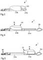
- Fig. 3the vacuum cleaner 1 is retracted and the first profile part 23a is to a high extent enclosed by the second profile part 23b.
- the handle 50is in a folded position.
- This vacuum cleaner set-upmay be suitable e.g. for vacuum cleaning of staircases.
- Fig. 4the vacuum cleaner 1 is extracted and only a small part of the first profile part 23a is enclosed by the second profile part 23b.
- the handle 50is in an open position.
- the housing 10is in a lower or second position B.
- This vacuum cleaner set-upmay be suitable e.g. during vacuum cleaning of floors when a relatively low point of gravity may be preferred.
- Fig. 5the vacuum cleaner 1 is extracted and only a small part of the first profile part 23a is enclosed by the second profile part 23b.
- the handle 50is in an open position.
- the housing 10is in an upper or first position A.
- This vacuum cleaner set-upmay be suitable e.g. during vacuum cleaning in situations where the nozzle 40 is higher up than the housing 10, such as when walls, high shelfs or ceilings are vacuum cleaned. Since the housing 10 is in the second position B, it will be relatively low when the vacuum cleaner has the nozzle 40 upwards. Thus, a relatively low point of gravity is achieved also during these vacuum cleaning operations. Further, this vacuum cleaner set-up may be advantageous for vacuum cleaning under low furniture's such as beds, sofas and the like. Since the housing 10 is in the first position A the nozzle 40 may reach far under a bed without being hindered by the housing 10.
- Fig. 6illustrates the vacuum cleaner 1 with only a small type of nozzle attached.
- the vacuum cleaner 1is retracted and the first profile part 23a is to a high extent enclosed by the second profile part 23b.
- the handle 50is in a folded position.
- This vacuum cleaner set-upmay be suitable e.g. for vacuum cleaning of tables, shelfs and similar.
- Fig. 7the vacuum cleaner 1 is extracted and only a small part of the first profile part 23a is enclosed by the second profile part 23b.
- the handle 50is in a closed position.
- the housing 10is in the first position A.
- This vacuum cleaner set-upmay be suitable e.g. during vacuum cleaning in situations where the first profile end 21 is higher up than the housing 10, such as when walls, high shelfs or ceilings are vacuum cleaned. Since the housing 10 is in the first position A, it will be relatively low when the vacuum cleaner has the first profile end 21 upwards. Thus, a relatively low point of gravity is achieved also during these vacuum cleaning operations.
- Fig. 8illustrates the vacuum cleaner 1 with a combined nozzle and a flexible tube 41 attached.
- the vacuum cleaner 1is retracted and the first profile part 23a is to a high extent enclosed by the second profile part 23b.
- the handle 50is in a folded position.
- This vacuum cleaner set-upmay be suitable e.g. for vacuum cleaning of tables, shelfs and similar.
- the housing 10may comprise a motor fan unit 12, one or more filters 13 and a housing air inlet 14.
- the housing 10may also comprise a bag, dust separation chamber or dust collector 19.
- the motor fan unitis capable of building up an underpressure, thereby causing an airflow 60 to flow from an air inlet 61 at the nozzle 40 to the housing air outlet 11 via the housing air inlet 14.
- Fig. 10is a schematic cross section of the vacuum cleaner set-up illustrated in Fig. 4 with the housing 10, the first profile part 23a and the second profile part 23b.
- Fig. 11is a schematic cross section of the vacuum cleaner set-up illustrated in Fig. 5 with the housing 10, the first profile part 23a and the second profile part 23b.
- a flexible hose 35is illustrated.
- the flexible hose 35can be arranged within the profile with a first end 36 in the first profile end and a second end 37 operatively connected to the opening 25 of the profile 23 and to the housing air inlet 14.
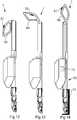
- Fig. 12is a side view of the vacuum cleaner 1 with the handle 50 in a folded position.
- Fig. 13is a side view of the vacuum cleaner 1 with the handle 50 in a semi-folded position and in Fig. 14 the vacuum cleaner 1 has the handle 50 in the open position.
- the handle 50may optionally comprise a control arrangement 51 for control of at least one of a fan effect, a nozzle function or any other vacuum cleaner function which may need to be adjustable.
- a vacuum cleaner system 70 with a chargeable battery 71 and a docking station 72are illustrated.
- the docking station 72is capable to charge the battery 71 of the vacuum cleaner.
- the vacuum cleaner 1may be powered via an electric cable instead of a battery.
- Fig. 15illustrates a cross-sectional view of the vacuum cleaner 1 according to some embodiments.
- the vacuum cleaner 1comprises the first profile part 23a, the second profile part 23b and the flexible hose 35.
- the first profile part 23acomprises a first rail 27a.
- the second profile part 23bcomprises a second rail 27b.
- the housingcomprises a housing base 16 which is arranged to be displaced along the first rail 27a and/or the second rail 27b.
- the housing base 16may comprise grooves 16a arranged to co-operate with the first rail 27a and second grooves 16b arranged to co-operate with the second rail 27b.
- the housing base 16easily may be slid/displaced along the profile.
- the housing air inlet(denominated 14 in Figs. 9-11 ) may be arranged in the housing base 16.
- the second end of the flexible hose(denominated 37 in Figs. 9-11 ) may be arranged to be attached to the housing base 16.
- the housing base 16comprises one or more brackets or sleeves which partly or fully may encloses the profile 23.
- the housing base 16may then be slid along a length of the profile 23 mainly co-operating with exterior surfaces of the first 23a and/or second 23b profile parts.
- a first sleeve partmay be arranged to be fit around the first profile part 23a and a second sleeve part may be arranged to be fitted around the second profile part 23b.
- Such embodimentsmay be designed with rails or may be designed without any rails.
- electrical cables 59are illustrated. Such cables may be arranged within an interstice 58 of a profile part. Such cables 59 may connect a control arrangement at a handle with other parts, such as the nozzle, fan and/or motor. In some embodiments sliding contacts are arranged within the interstice 58.
- Fig. 16is illustrated an embodiment in which the at least one opening comprises two distinct openings 25' along the length of the first profile part 23a and the second profile part 23b.
- Covering means 26 in form of lidsmay be arranged to allow airflow to the housing 10 and to block openings 25' at other positions.
- the lidsmay e.g. be biased into closed positions and forced to be opened by the housing 10.
- the housing, profile arrangement, nozzle and handlemay, at least partly, be made of plastics, metal or any other suitable material.
Landscapes
- Engineering & Computer Science (AREA)
- Mechanical Engineering (AREA)
- Robotics (AREA)
- Electric Vacuum Cleaner (AREA)
- Nozzles For Electric Vacuum Cleaners (AREA)
Description
- Embodiments herein relate to a vacuum cleaner. More particularly, embodiments herein relate to an upright/stick type vacuum cleaner and/or a handheld vacuum cleaner. Embodiments herein further relate to a vacuum cleaner system comprising a vacuum cleaner and a docking station.
- Different kinds of stick type vacuum cleaners are known. This type of vacuum cleaner generally have an elongated body with a nozzle in one end and a handle in the other end. A housing with a fan and filter may be attached to the elongated body and may extend substantially in parallel thereto. Such housing may comprise a fan and motor, a dust collector, a filter and other necessary parts.
- Handheld vacuum cleaners allow a user to remove dust and debris in a relatively easy and efficient manner and may be operated with a single hand grip.
- In some stick type vacuum cleaners the housing is detachable from the elongated body and may be used independently as a handheld vacuum cleaner separate from the elongated body. This may be practical e.g. for sucking up crumbs from tables and similar. This also allow a user to reach surfaces where a nozzle of the body would not fit. In
EP1969988 an example of such a vacuum cleaner is disclosed. - A drawback with many upright/stick type vacuum cleaners is that it is difficult to vacuum clean under beds, sofas and the like, since the housing may restrict how far the nozzle may reach. In other words, the housing may hit the bed / sofa when a dimension of the housing is larger than the height between the bed / sofa and the floor to be cleaned.
- Further, it may be a challenge to efficiently use the vacuum cleaner on surfaces above a certain height, such as walls, shelfs and ceilings, since the design of the handheld vacuum cleaner is generally optimized for floor-cleaning.
- In
GB1151990 GB1151990 GB1151990 - An object is to provide a more efficient vacuum cleaner.
- According to an embodiment, the object is achieved by a vacuum cleaner comprising; a housing comprising a motor fan unit for generating an airflow, a housing air outlet and a housing air inlet, and a profile arrangement comprising a first profile end for attachment of a nozzle, a profile handle end for attachment of a handle and a profile extending between the first profile end and the profile handle end, and an airflow channel extending from the first profile end to the housing air outlet via the housing air inlet, for allowing an airflow from the first profile end to the housing air outlet. The profile arrangement comprises a first profile part and a second profile part, the second profile part is arranged to at least partly enclose the first profile part and the first profile part is slidable into the second profile part for adjustment of a length of the profile and that the housing is arranged to be moveably attached to the profile, such that the housing is moveable along at least a part of the length of the profile.
- Since the first profile part is slidable or retractable into the second profile part and the housing is arranged to be moveably attached to the profile such that the housing is moveable along at least a part of the length of the profile a very flexible vacuum cleaner is achieved. A user may extend the profile when necessary, such that he/she may use the vacuum cleaner in a standing position, and may retract the profile, e.g. when using the vacuum cleaner in a staircase or similar. Further, he/she may move the housing to a position relatively near the nozzle when vacuum cleaning a floor and may move the housing to a position closer to the grip portion e.g. when he/she is vacuum cleaning walls, ceilings etc. A user may thus change both the length of the profile and the gravity point of the vacuum cleaner. Hereby the vacuum cleaner enables efficient, flexible and ergonomic vacuum cleaning. This further allows the vacuum cleaner to have relatively more weight if necessary. This has proven to be very useful when the vacuum cleaner is equipped with a powerful motor and a battery with some weight.
- According to some embodiments the profile comprises at least one opening, the at least one opening being a slit shaped opening, having a first slit opening section in the first profile part and a second slit opening section in the second profile part. The housing is arranged to be movably attached to the profile at different positions of the first and/or the second profile part and an airflow from the nozzle / first profile end can enter the housing via the first slit opening section or the second slit opening section.
- According to some embodiments the profile comprises opening cover means, arranged to allow the airflow channel to a section of the opening where the housing air inlet is positioned. According to some embodiments the opening cover means are arranged to close off the remaining sections of the opening. This enables an efficient flow and a strong suction force from the first profile end to the housing. The opening covering means also prevent smaller objects from getting stuck in the opening and may prevent a user from jamming his/her fingers in the opening when moving the housing along the length of the profile.
- According to some embodiments the opening cover means is at least one of; a flexible cover strip, one or more elastic sealing elements, one or more lids and a zipper arrangement. Hereby efficient covering of the opening is achieved.
- According to some embodiments the vacuum cleaner comprises a flexible hose with a first end in the first profile end and a second end operatively connected to the housing air inlet. A flexible hose is a reliable and efficient solution for connecting the first profile end with the housing air inlet. The flexible hose also provides for an efficient and obstacle-free airflow between the first profile end and the housing air inlet.
- According to some embodiments the flexible hose at least partly is enclosed within the profile, and the second end is operatively connected to the housing air inlet via the opening of the profile. The flexible hose is then well-protected by the profile.
- According to some embodiments the first profile part comprises a first rail, the second profile part comprises a second rail and the housing comprises a housing base which is arranged to be displaced along the first rail and/or the second rail. Hereby the housing easily and reliably is displaceable between different positions along the profile. The housing may be permanently or releasable attached to the housing base. According to some embodiments the housing air inlet is arranged in the housing base and the second end of the flexible hose is arranged to be attached to the housing base.
- According to some embodiments the profile comprises at least one opening which comprises two or more distinct openings along the length of the profile. Hereby the housing easily may be moved between different distinct positions along the profile. According to some embodiments the housing is attachable to the profile in positions along the length of the profile for which the housing air inlet is substantially aligned to one distinct opening of the two or more distinct openings and according to some embodiments one or more distinct openings which is/are not substantially aligned to the air inlet is/are closed off by the opening covering means. This enables an efficient flow and a strong suction force from the first profile end to the housing.
- According to some embodiments the vacuum cleaner comprises a handle, attached to the profile arrangement, preferably pivotally attached to the profile handle end. The handle allows a user to adjust a handle positions in accordance to his/her preferences. The handle also may be used to extend or shorten a length of the vacuum cleaner.
- According to some embodiments the handle comprises a control arrangement for control of at least one of a fan effect and a nozzle function. Hereby a flow rate of air may be adjusted. A user may also efficiently control one or more nozzle functions, such as nozzle lights, a brush roller or the like via the control arrangement.
- According to some embodiments the vacuum cleaner comprises a nozzle with a nozzle air inlet, attachable to the first profile end. A nozzle may be useful in many applications, such as during vacuum cleaning of a floor.
- According to some embodiments the vacuum cleaner comprises a first side which is arranged to face upwards or oblique upwards when the vacuum cleaner is positioned in an operating position and a second side, arranged to face downwards or oblique downwards when the vacuum cleaner is positioned in an operating position, and in that the housing is attached to the first side. Hereby vacuum cleaning under sofas, beds etc. is facilitated.
- According to some embodiments the vacuum cleaner comprises a chargeable battery for powering of e.g. the motor fan unit. A battery may be a substantial part of a weight of the vacuum cleaner. Embodiments herein has proven to efficiently "compensate" for this weight since a user may both select a suitable length and select where the point of gravity should be located along the profile.
- An object herein is also to provide a more efficient vacuum cleaner system. According to an embodiment, the object is achieved by a vacuum cleaner system comprising a docking station and a vacuum cleaner according to embodiments herein, said docking station being capable to charge the battery of the vacuum cleaner. Hereby an efficient, flexible and ergonomic vacuum cleaner system is achieved.
- The various aspects of embodiments herein, including its particular features and advantages, will be readily understood from the following detailed description and the accompanying drawings, in which:
Fig. 1 illustrates a perspective view of a vacuum cleaner according to some embodiments with the housing in a first position,Fig. 2 illustrates theFig. 1 vacuum cleaner with the housing in a second position,Fig. 3 illustrates a side view of the vacuum cleaner according to some embodiments when retracted,Fig. 4 illustrates theFig 3 . vacuum cleaner when extracted and with the housing in the second position,Fig. 5 illustrates theFig. 4 vacuum cleaner with the housing in the first position,Fig. 6 illustrates a vacuum cleaner according to some embodiments when retracted,Fig. 7 illustrates a vacuum cleaner according to some embodiments,Fig. 8 illustrates a vacuum cleaner according to some other embodiments,Fig. 9 illustrates a cross section of theFig. 3 vacuum cleaner,Fig. 10 illustrates a cross section of theFig. 4 vacuum cleaner,Fig. 11 illustrates a cross section of theFig. 5 vacuum cleaner,Fig. 12 illustrates a vacuum cleaner according to some other embodiments with a handle in a folded position,Fig. 13 illustrates a vacuum cleaner according to some other embodiments with the handle in a semi-folded position,Fig. 14 illustrates a vacuum cleaner system and a vacuum cleaner according to some other embodiments with the handle in an open position,Fig. 15 illustrates a cross-section of the vacuum cleaner, andFig. 16 schematically illustrates a vacuum cleaner according to some embodiments.- Embodiments herein will now be described more fully with reference to the accompanying drawings, in which embodiments are shown. Well-known functions or constructions will not necessarily be described in detail for brevity and/or clarity.
Fig. 1 andFig. 2 illustrate avacuum cleaner 1 according to some embodiments. InFig. 1 and Fig. 2 thevacuum cleaner 1 is illustrated in perspective view.- The
vacuum cleaner 1 comprises ahousing 10. Thehousing 10 may be made as a hollow body or structure for housing some parts of thevacuum cleaner 1. Thehousing 10 may comprise a motor fan unit for generating an airflow. A schematic airflow and a schematic motor fan unit are illustrated inFigs. 9-11 . Thehousing 10 also comprises ahousing air outlet 11 and a housing air inlet, also illustrated inFigs. 9-11 . - The
vacuum cleaner 1 further comprises aprofile arrangement 20. Theprofile arrangement 20 comprises afirst profile end 21, aprofile grip portion 22 and aprofile 23 extending between thefirst profile end 21 and the profile grip portion 22.Theprofile arrangement 20 comprises at least oneopening 25 for allowing an airflow from thefirst profile end 21 to the housing air inlet. Theprofile arrangement 20 may also be referred to as an open profile arrangement, an elongated profile arrangement or the like. Theprofile 23 may also be referred to as an open profile, an elongated profile or the like. Theopening 25 can for example be a slit shaped opening, having a firstslit opening section 25a in thefirst profile part 23a and a secondslit opening section 25b in thesecond profile part 23b. In other embodiments, illustrated in conjunction withFig. 16 , the at least oneopening 25 comprises two or more distinct openings25' along the length of theprofile 23. As illustrated inFig. 1 and 2 theopening 25 may be radially arranged or directed, in contrast to any end orifices of theprofile 23. - The
profile arrangement 20 comprises thefirst profile part 23a and thesecond profile part 23b. Thesecond profile part 23b is arranged to at least partly enclose thefirst profile part 23a. In the embodiment illustrated inFigs. 1 and 2 thesecond profile part 23b is illustrated closest to anozzle 40 of thevacuum cleaner 1. In other embodiments thefirst profile part 23a is closest to thenozzle 40. In other words, a profile part with a larger dimension, into which the other profile part may be slid, can selectively be arranged at an upper or lower position. Thefirst profile part 23a is slidable or retractable into thesecond profile part 23b for adjustment of a length of theprofile 23. Thefirst profile part 23a and thesecond profile part 23b together form atelescopic profile 23. Theprofile arrangement 20 may comprise alock 24 or similar for locking thefirst profile part 23a and thesecond profile part 23b relatively each other. - In the embodiments illustrated in
Figs. 1 and 2 also ahandle 50 is attached to theprofile grip portion 22. - The vacuum cleaner illustrated in
Figs. 1 and 2 comprises opening cover means26. The opening cover means 26 are arranged to allow an airflow to a section of theopening 25 where thehousing 10 with its air inlet is positioned and to close off the remaining sections of theopening 25. The opening cover means 26 can comprise and close off sections of theopening 25. Alternatively the opening cover means 26 comprises a flexible cover strip. Such flexible cover strip may be designed with the same working principle as an extendable / retractable measure tape and may comprise one or two parts. The opening cover means 26 may in some embodiments comprise of one or more elastic sealing elements for selectively closing off theopening 25. The opening cover means 26 may also comprise a zipper arrangement or the like for selectively closing off the opening. The opening cover means 26 may also/alternatively comprise one or more lids, as illustrated inFig. 16 . - The
housing 10 is arranged to be attached to theprofile 23 at different positions of thefirst profile part 23a and/or thesecond profile part 23b along the length of theprofile 23. InFig. 1 thehousing 10 is arranged in a first positionA and inFig. 2 the housing is arranged in a second positionB. Since the first position is most far from the nozzle it may sometimes be referred to as an upper position and the second position may sometimes be referred to as a lower position when the vacuum cleaner is arranged in a standup position. - It is understood that the
housing 10 can be arranged in a number of different positions along the length of theprofile 23. The first position A and the second position B may serve as examples of housing positions. In some embodiments thehousing 10 may be arranged in e.g. 2-6 distinct positions along the length of theprofile 23. In some embodiments thehousing 10 may be arranged to be freely slidable and to be attachable at any position along the length of theprofile 23. The housing may be fixed in a selected position by a latch of any kind and released when the latch is opened. - In
Fig. 3 thevacuum cleaner 1 is retracted and thefirst profile part 23a is to a high extent enclosed by thesecond profile part 23b. Thehandle 50 is in a folded position. This vacuum cleaner set-up may be suitable e.g. for vacuum cleaning of staircases. - In
Fig. 4 thevacuum cleaner 1 is extracted and only a small part of thefirst profile part 23a is enclosed by thesecond profile part 23b. Thehandle 50 is in an open position. Thehousing 10 is in a lower or second position B. This vacuum cleaner set-up may be suitable e.g. during vacuum cleaning of floors when a relatively low point of gravity may be preferred. - In
Fig. 5 thevacuum cleaner 1 is extracted and only a small part of thefirst profile part 23a is enclosed by thesecond profile part 23b. Thehandle 50 is in an open position. Thehousing 10 is in an upper or first position A. This vacuum cleaner set-up may be suitable e.g. during vacuum cleaning in situations where thenozzle 40 is higher up than thehousing 10, such as when walls, high shelfs or ceilings are vacuum cleaned. Since thehousing 10 is in the second position B, it will be relatively low when the vacuum cleaner has thenozzle 40 upwards. Thus, a relatively low point of gravity is achieved also during these vacuum cleaning operations. Further, this vacuum cleaner set-up may be advantageous for vacuum cleaning under low furniture's such as beds, sofas and the like. Since thehousing 10 is in the first position A thenozzle 40 may reach far under a bed without being hindered by thehousing 10. Fig. 6 illustrates thevacuum cleaner 1 with only a small type of nozzle attached. Thevacuum cleaner 1 is retracted and thefirst profile part 23a is to a high extent enclosed by thesecond profile part 23b. Thehandle 50 is in a folded position. This vacuum cleaner set-up may be suitable e.g. for vacuum cleaning of tables, shelfs and similar.- In
Fig. 7 thevacuum cleaner 1 is extracted and only a small part of thefirst profile part 23a is enclosed by thesecond profile part 23b. Thehandle 50 is in a closed position. Thehousing 10 is in the first position A. This vacuum cleaner set-up may be suitable e.g. during vacuum cleaning in situations where thefirst profile end 21 is higher up than thehousing 10, such as when walls, high shelfs or ceilings are vacuum cleaned. Since thehousing 10 is in the first position A, it will be relatively low when the vacuum cleaner has the first profile end 21 upwards. Thus, a relatively low point of gravity is achieved also during these vacuum cleaning operations. Fig. 8 illustrates thevacuum cleaner 1 with a combined nozzle and aflexible tube 41 attached. Thevacuum cleaner 1 is retracted and thefirst profile part 23a is to a high extent enclosed by thesecond profile part 23b. Thehandle 50 is in a folded position. This vacuum cleaner set-up may be suitable e.g. for vacuum cleaning of tables, shelfs and similar.- In
Fig. 9, Fig. 10 andFig. 11 schematic cross sections of thevacuum cleaner 1 are illustrated. Thehousing 10 may comprise amotor fan unit 12, one ormore filters 13 and ahousing air inlet 14. Thehousing 10 may also comprise a bag, dust separation chamber ordust collector 19. The motor fan unit is capable of building up an underpressure, thereby causing anairflow 60 to flow from anair inlet 61 at thenozzle 40 to thehousing air outlet 11 via thehousing air inlet 14.Fig. 10 is a schematic cross section of the vacuum cleaner set-up illustrated inFig. 4 with thehousing 10, thefirst profile part 23a and thesecond profile part 23b.Fig. 11 is a schematic cross section of the vacuum cleaner set-up illustrated inFig. 5 with thehousing 10, thefirst profile part 23a and thesecond profile part 23b. - In the embodiments illustrated in
Figs. 9-11 aflexible hose 35 is illustrated. Theflexible hose 35 can be arranged within the profile with afirst end 36 in the first profile end and asecond end 37 operatively connected to theopening 25 of theprofile 23 and to thehousing air inlet 14. Fig. 12 is a side view of thevacuum cleaner 1 with thehandle 50 in a folded position.Fig. 13 is a side view of thevacuum cleaner 1 with thehandle 50 in a semi-folded position and inFig. 14 thevacuum cleaner 1 has thehandle 50 in the open position. Thehandle 50 may optionally comprise acontrol arrangement 51 for control of at least one of a fan effect, a nozzle function or any other vacuum cleaner function which may need to be adjustable.- In
Fig. 14 avacuum cleaner system 70 with achargeable battery 71 and adocking station 72 are illustrated. Thedocking station 72 is capable to charge thebattery 71 of the vacuum cleaner. In some embodiment thevacuum cleaner 1 may be powered via an electric cable instead of a battery. Fig. 15 illustrates a cross-sectional view of thevacuum cleaner 1 according to some embodiments. In the embodiment depicted inFig. 15 thevacuum cleaner 1 comprises thefirst profile part 23a, thesecond profile part 23b and theflexible hose 35. Thefirst profile part 23a comprises afirst rail 27a. Thesecond profile part 23b comprises asecond rail 27b. The housing comprises ahousing base 16 which is arranged to be displaced along thefirst rail 27a and/or thesecond rail 27b. Thehousing base 16 may comprisegrooves 16a arranged to co-operate with thefirst rail 27a andsecond grooves 16b arranged to co-operate with thesecond rail 27b. Hereby thehousing base 16 easily may be slid/displaced along the profile. The housing air inlet (denominated 14 inFigs. 9-11 ) may be arranged in thehousing base 16. The second end of the flexible hose (denominated 37 inFigs. 9-11 ) may be arranged to be attached to thehousing base 16.- In some embodiments the
housing base 16 comprises one or more brackets or sleeves which partly or fully may encloses theprofile 23. Thehousing base 16 may then be slid along a length of theprofile 23 mainly co-operating with exterior surfaces of the first 23a and/or second 23b profile parts. A first sleeve part may be arranged to be fit around thefirst profile part 23a and a second sleeve part may be arranged to be fitted around thesecond profile part 23b. Such embodiments may be designed with rails or may be designed without any rails. - In
Fig. 15 electrical cables 59 are illustrated. Such cables may be arranged within aninterstice 58 of a profile part.Such cables 59 may connect a control arrangement at a handle with other parts, such as the nozzle, fan and/or motor. In some embodiments sliding contacts are arranged within theinterstice 58. - In
Fig. 16 is illustrated an embodiment in which the at least one opening comprises two distinct openings 25' along the length of thefirst profile part 23a and thesecond profile part 23b. Covering means 26 in form of lids may be arranged to allow airflow to thehousing 10 and to block openings 25' at other positions. The lids may e.g. be biased into closed positions and forced to be opened by thehousing 10. - The housing, profile arrangement, nozzle and handle may, at least partly, be made of plastics, metal or any other suitable material.
Claims (18)
- A vacuum cleaner (1) comprising;- a housing (10) comprising a motor fan unit (12) for generating an airflow, a housing air outlet (11) and a housing air inlet (14), and- a profile arrangement (20) comprising a first profile end (21) for attachment of a nozzle (40), a profile handle end (22) for attachment of a handle (50) and a profile (23) extending between the first profile end (21) and the profile handle end (22), and- an airflow channel (60) extending from the first profile end (21) to the housing air outlet (11) via the housing air inlet (14), for allowing an airflow from the first profile end (21) to the housing air outlet (11),characterized in that the profile arrangement (20) comprises a first profile part (23a) and a second profile part (23b), the second profile part (23b) is arranged to at least partly enclose the first profile part (23a) and the first profile part (23a) is slidable into the second profile part (23b) for adjustment of a length of the profile (23) and that the housing (10) is arranged to be moveably attached to the profile (23), such that the housing (10) is moveable along at least a part of the length of the profile (23).
- The vacuum cleaner (1) according to claim 1wherein the profile (23) comprises at least one opening (25), the at least one opening (25) being a slit shaped opening, having a first slit opening section (25a) in the first profile part (23a) and a second slit opening section (25b) in the second profile part (23b).
- The vacuum cleaner (1) according to claim 1 or 2wherein the profile (23) comprises opening cover means (26), arranged to allow the airflow channel (60) to a section of the opening (25) where the housing air inlet (14) is positioned.
- The vacuum cleaner (1) according to claim 3wherein the opening cover means (26) are arranged to close off the remaining sections of the opening (25).
- The vacuum cleaner (1) according to claim 3 or 4wherein the opening cover means (26) is at least one of;- a flexible cover strip,- one or more elastic sealing elements,- one or more lids and- a zipper arrangement.
- The vacuum cleaner (1) according to any one of the preceding claimswherein it comprises a flexible hose (35) with a first end (36) in the first profile end (21) and a second end (37) operatively connected to the housing air inlet (14).
- The vacuum cleaner (1) according to claimwherein the flexible hose (35) at least partly is enclosed within the profile (23), and where the second end (37) is operatively connected to the housing air inlet (14) via the opening (25) of the profile (23).
- The vacuum cleaner (1) according to any one of the preceding claimswherein the first profile part (23a) comprises a first rail (27a), the second profile part (23b) comprises a second rail (27b) and the housing (10) comprises a housing base (16) which is arranged to be displaced along the first rail (27a) and/or the second rail (27b).
- The vacuum cleaner (1) according to claim 8 when dependent on claim 6 or 7,wherein the housing air inlet (14) is arranged in the housing base (16) and wherein the second end (37) of the flexible hose (35) is arranged to be attached to the housing base (16).
- The vacuum cleaner (1) according to claim 1wherein it comprises at least one opening (25) which comprises two or more distinct openings (25') along the length of the profile (23).
- The vacuum cleaner (1) according to claim 10wherein the housing (10) is attachable to the profile (23) in positions along the length of the profile (23) for which the housing air inlet (14) is substantially aligned to one distinct opening (25') of the two or more distinct openings (25').
- The vacuum cleaner (1) according to claim 11 when dependent on claim 3 or 4 or 5wherein one or more distinct openings (25') which is/are not substantially aligned to the air inlet (14) is/are closed off by the opening covering means (26).
- The vacuum cleaner (1) according to any one of the preceding claimswherein the vacuum cleaner (1) comprises a handle (50), attached to the profile arrangement (23), preferably pivotally attached to the profile handle end (22).
- The vacuum cleaner (1) according to claim 13,wherein the handle (50) comprises a control arrangement (51) for control of at least one of a fan effect and a nozzle function.
- The vacuum cleaner (1) according to any one of the preceding claimswherein the vacuum cleaner (1) comprises a nozzle (40) with a nozzle air inlet, attachable to the first profile end (21).
- The vacuum cleaner (1) according to any one of the preceding claimswherein the vacuum cleaner (1) comprises a first side which is arranged to face upwards or oblique upwards when the vacuum cleaner (1) is positioned in an operating position and a second side, arranged to face downwards or oblique downwards when the vacuum cleaner (1) is positioned in an operating position, and in that the housing (10) is attached to the first side.
- The vacuum cleaner (1) according to any one of the preceding claimswherein the vacuum cleaner (1) comprises a chargeable battery (71) for powering of e.g. the motor fan unit (12).
- A vacuum cleaner system (70) comprising a docking station (72) and a vacuum cleaner (1) according to claim 17, said docking station (72) being capable to charge the battery (71) of the vacuum cleaner (1).
Applications Claiming Priority (1)
| Application Number | Priority Date | Filing Date | Title |
|---|---|---|---|
| PCT/EP2016/059339WO2017186280A1 (en) | 2016-04-27 | 2016-04-27 | Vacuum cleaner and vacuum cleaner system |
Publications (2)
| Publication Number | Publication Date |
|---|---|
| EP3448216A1 EP3448216A1 (en) | 2019-03-06 |
| EP3448216B1true EP3448216B1 (en) | 2020-02-05 |
Family
ID=55809134
Family Applications (1)
| Application Number | Title | Priority Date | Filing Date |
|---|---|---|---|
| EP16718692.3AActiveEP3448216B1 (en) | 2016-04-27 | 2016-04-27 | Vacuum cleaner and vacuum cleaner system |
Country Status (6)
| Country | Link |
|---|---|
| US (1) | US11058267B2 (en) |
| EP (1) | EP3448216B1 (en) |
| JP (1) | JP6849165B2 (en) |
| KR (1) | KR102496980B1 (en) |
| CN (1) | CN109068906A (en) |
| WO (1) | WO2017186280A1 (en) |
Families Citing this family (26)
| Publication number | Priority date | Publication date | Assignee | Title |
|---|---|---|---|---|
| EP3448216B1 (en) | 2016-04-27 | 2020-02-05 | Aktiebolaget Electrolux | Vacuum cleaner and vacuum cleaner system |
| USD915013S1 (en) | 2017-07-24 | 2021-03-30 | Aktiebolaget Electrolux | Vacuum cleaner |
| US11707167B2 (en)* | 2017-12-04 | 2023-07-25 | Transform Sr Brands Llc | Stick vacuum with indexing vacuum head assembly |
| EP3723571B1 (en)* | 2017-12-14 | 2023-09-27 | Aktiebolaget Electrolux | Vacuum cleaner and valve |
| US11534042B2 (en) | 2017-12-15 | 2022-12-27 | Aktiebolaget Electrolux | Vacuum cleaner |
| WO2019120542A1 (en)* | 2017-12-21 | 2019-06-27 | Aktiebolaget Electrolux | Vacuum cleaner |
| US20190216277A1 (en)* | 2018-01-15 | 2019-07-18 | Intelliclean Solutions, Llc | Upright vacuum with telescoping head |
| WO2019172962A1 (en) | 2018-03-09 | 2019-09-12 | Midea America Corp. | Surface cleaning apparatus |
| JP6941784B2 (en)* | 2018-03-30 | 2021-09-29 | パナソニックIpマネジメント株式会社 | Vacuum cleaner |
| WO2019214819A1 (en) | 2018-05-09 | 2019-11-14 | Aktiebolaget Electrolux | Vacuum cleaner and vacuum cleaner system |
| WO2019233554A1 (en)* | 2018-06-05 | 2019-12-12 | Aktiebolaget Electrolux | Self-stand mode for stick vacuum cleaner |
| WO2020006182A1 (en)* | 2018-06-27 | 2020-01-02 | Bissell Inc. | Surface cleaning apparatus |
| CN109512334B (en)* | 2018-11-28 | 2021-04-20 | 苏州凯丽达电器有限公司 | Assembly of portable dust collector and charging terminal base |
| CN111358340B (en)* | 2018-12-25 | 2022-01-28 | 江苏美的清洁电器股份有限公司 | Cleaning device |
| CN111358339B (en)* | 2018-12-25 | 2021-07-30 | 江苏美的清洁电器股份有限公司 | Cleaning device |
| CN110432820B (en)* | 2019-08-09 | 2021-05-07 | 苏州诚河清洁设备有限公司 | Vacuum cleaner with a vacuum cleaner head |
| CN112971592A (en)* | 2019-12-16 | 2021-06-18 | 江苏美的清洁电器股份有限公司 | Vertical dust collector |
| CN113768405B (en)* | 2020-06-09 | 2022-09-16 | 江苏美的清洁电器股份有限公司 | Vertical dust collector |
| EP4226830A4 (en)* | 2020-10-08 | 2024-11-20 | LG Electronics Inc. | MODULAR CLEANING DEVICE |
| US11832779B2 (en)* | 2020-11-20 | 2023-12-05 | Origyn LLC | Vacuum cleaner |
| US11659968B2 (en) | 2021-05-25 | 2023-05-30 | Bissell Inc. | Surface cleaning apparatus with a brake assembly |
| USD1047325S1 (en)* | 2021-08-24 | 2024-10-15 | Emerson Electric Co. | Backpack vacuum cleaner |
| CN116076941B (en)* | 2021-11-05 | 2025-08-19 | 追觅创新科技(苏州)有限公司 | Cleaning equipment |
| USD1070209S1 (en)* | 2022-05-09 | 2025-04-08 | Ningbo Shijia Cleaning Tools Co., Ltd | Vacuum |
| JP1777706S (en)* | 2023-04-19 | 2024-08-14 | Handheld vacuum cleaner | |
| USD1091031S1 (en)* | 2024-02-20 | 2025-08-26 | Yunjing Intelligence Innovation (Shenzhen) Co., Ltd. | Cleaning device |
Family Cites Families (127)
| Publication number | Priority date | Publication date | Assignee | Title |
|---|---|---|---|---|
| US1355553A (en) | 1912-02-02 | 1920-10-12 | United Electric Company | Suction cleaning-nozzle |
| US1161908A (en) | 1912-02-13 | 1915-11-30 | United Electric Company | Suction cleaning-nozzle. |
| US1139736A (en) | 1912-10-16 | 1915-05-18 | Domestic Appliances Company | Cleaning-tool. |
| US2074042A (en) | 1935-02-09 | 1937-03-16 | Bank Edward Carl | Swivel connection for vacuum cleaner nozzles |
| GB468920A (en) | 1935-11-26 | 1937-07-15 | Electrolux Ltd | Improvements in nozzles for vacuum cleaners |
| DE742606C (en) | 1940-10-05 | 1943-12-08 | Fisker & Nielsen As | Vacuum cleaner mouthpiece |
| US2530886A (en) | 1946-11-09 | 1950-11-21 | Maisel Florence | Steering means for manually propelled devices |
| US2660457A (en) | 1950-04-14 | 1953-11-24 | Adelaide H Mallon | Telescopic handle |
| US2867833A (en) | 1955-04-06 | 1959-01-13 | Hoover Co | Convertible suction cleaners |
| US3306634A (en) | 1963-02-07 | 1967-02-28 | Pul Vac Inc | Articulate joint |
| SE334712B (en)* | 1967-03-23 | 1971-05-03 | Electrolux Ab | |
| GB1472384A (en) | 1975-01-24 | 1977-05-04 | Wright G | Vacuum cleaners |
| JPS5261173U (en)* | 1975-10-06 | 1977-05-04 | ||
| DE3206464A1 (en) | 1982-02-23 | 1983-09-01 | Düpro AG, 8590 Romanshorn | CLEANER |
| US4571772A (en) | 1982-12-27 | 1986-02-25 | Prototypes, Ltd. | Upright vacuum cleaning appliance |
| US4704765A (en) | 1984-06-11 | 1987-11-10 | Sharp Kabushiki Kaisha | Portable vacuum cleaner |
| SE8502774D0 (en) | 1985-06-05 | 1985-06-05 | Stefan Moszkowski | SUCTION CHANNEL FOR AIR TRANSPORT |
| US4653137A (en) | 1986-02-20 | 1987-03-31 | Eugene Fleischhauer | Vacuum cleaner attachments |
| US4638527A (en) | 1986-02-20 | 1987-01-27 | Fleischhauer Eugene T | Vacuum cleaner attachments |
| US4700429A (en) | 1986-10-23 | 1987-10-20 | Whirlpool Corporation | Quick release wand for cannister vacuum cleaner |
| JPS6383145U (en)* | 1986-11-21 | 1988-06-01 | ||
| JPS63125947U (en)* | 1987-02-10 | 1988-08-17 | ||
| DE3909408A1 (en) | 1989-03-22 | 1990-10-18 | Stein & Co Gmbh | HAND VACUUM CLEANER |
| US5347679A (en) | 1993-01-07 | 1994-09-20 | Royal Appliance Mfg. Co. | Stick type vacuum cleaner |
| US5323510A (en) | 1993-07-09 | 1994-06-28 | Redding Glenn K | Vacuum cleaner having improved steering features |
| US5584436A (en) | 1994-11-18 | 1996-12-17 | White Consolidated Industires, Inc. | Portable blower with detachable nozzle |
| AU701818B2 (en) | 1995-10-12 | 1999-02-04 | Nilfisk A/S | A suction pipe for a suction cleaner |
| US6065183A (en) | 1995-10-12 | 2000-05-23 | Nilfisk A/S | Connection element for a mouthpiece |
| US5797162A (en) | 1995-12-06 | 1998-08-25 | Royal Appliance Mfg. Co. | Extendable hose for a vacuum cleaner |
| US6108861A (en) | 1995-12-06 | 2000-08-29 | Royal Appliance Mfg. Co. | Extendable hose for a vacuum cleaner |
| DE19617066A1 (en) | 1996-04-29 | 1997-10-30 | Vorwerk Co Interholding | vacuum cleaner |
| DE19630286A1 (en) | 1996-07-26 | 1998-01-29 | Miele & Cie | Vacuum cleaner |
| US5794305A (en) | 1996-12-17 | 1998-08-18 | Weger; Kenneth J. | Articulation device for a vacuum cleaner |
| ES2179388T3 (en) | 1997-01-21 | 2003-01-16 | Vorwerk Co Interholding | POWDER VACUUM DRIVER THROUGH AN ELECTRIC MOTOR, ESPECIALLY POWDER VACUUM SYSTEM. |
| DE19738329A1 (en) | 1997-09-02 | 1999-03-04 | Bosch Siemens Hausgeraete | Hose arrangement for a vacuum cleaner |
| US6055703A (en) | 1997-10-14 | 2000-05-02 | Oreck Holdings Llc | Upright vacuum cleaner having improved steering apparatus with a lock out feature |
| SE9800405D0 (en)* | 1998-02-12 | 1998-02-12 | Electrolux Ab | Handle for a vacuum cleaner |
| CN2321380Y (en) | 1998-03-25 | 1999-06-02 | 潘景良 | Telescopic pipe for suction cleaner |
| US6345408B1 (en) | 1998-07-28 | 2002-02-12 | Sharp Kabushiki Kaisha | Electric vacuum cleaner and nozzle unit therefor |
| JP3151746B2 (en) | 1999-03-18 | 2001-04-03 | 株式会社日立製作所 | Suction body of vacuum cleaner and vacuum cleaner provided with this suction body |
| CN1111386C (en) | 2000-03-30 | 2003-06-18 | 胡岳安 | Telescopic steel pipe of suction cleaner |
| EP1282375B1 (en) | 2000-05-11 | 2008-09-03 | Koninklijke Philips Electronics N.V. | Suction attachment comprising a rotatable foot and a displaceable brush |
| KR100389289B1 (en) | 2000-09-22 | 2003-06-27 | 주식회사 대우일렉트로닉스 | Vacuum cleaner |
| JP3788755B2 (en) | 2001-08-29 | 2006-06-21 | シャープ株式会社 | Vacuum cleaner |
| US6823559B2 (en) | 2002-02-07 | 2004-11-30 | Wessel-Werk Gmbh | Front brush attachment device for vacuum cleaner |
| US20040134016A1 (en) | 2003-01-10 | 2004-07-15 | Royal Appliance Manufacturing Company | Suction wet jet mop |
| SE0300355D0 (en) | 2003-02-10 | 2003-02-10 | Electrolux Ab | Hand held vacuum cleaner |
| EP1449476B1 (en) | 2003-02-20 | 2008-08-27 | Wessel-Werk Gmbh | Nozzle for smooth surfaces and for textile floor coverings |
| DE10312906B4 (en) | 2003-02-20 | 2006-05-04 | Wessel-Werk Gmbh | Staubstaugerdüse for smooth floors and textile floor coverings |
| ITUD20030107A1 (en)* | 2003-05-20 | 2004-11-21 | De Longhi Spa | MULTIFUNCTIONAL ELECTRIC CLEANING EQUIPMENT. |
| DE202004000425U1 (en) | 2004-01-14 | 2004-04-15 | Fischer-Rohrtechnik Gmbh | Telescopic vacuum cleaner tube with means for conveying electrostatic charges away with a spring arrangement to ensure contact in the open and closed position of the telescopic tubes |
| US7353564B2 (en) | 2004-02-03 | 2008-04-08 | Robert Wertz | Vacuum sweeper |
| KR100642076B1 (en) | 2004-07-01 | 2006-11-10 | 삼성광주전자 주식회사 | Suction structure assembly and vacuum cleaner with same |
| GB2416482B (en) | 2004-07-22 | 2007-12-05 | Techtronic Ind Co Ltd | Hose assembly for suction cleaner |
| DE102004052306A1 (en) | 2004-10-16 | 2006-04-20 | Stein & Co Gmbh | Device for arranging a suction attachment |
| DE102004058556A1 (en) | 2004-12-03 | 2006-06-08 | Miele & Cie. Kg | Suction hose for vacuum cleaner |
| US7805804B2 (en) | 2004-12-21 | 2010-10-05 | Royal Appliance Mfg. Co. | Steerable upright vacuum cleaner |
| DE102004061971B4 (en) | 2004-12-23 | 2012-04-26 | Wessel-Werk Gmbh | Floor nozzle for vacuum cleaner |
| DE202005013078U1 (en) | 2005-08-18 | 2005-11-24 | Tong, Sammy Fai Sai | Method for locking a telescopic suction tube inner and outer tubes has a longitudinal groove in the inner tube with holes in which a ball in a control block on the outer tube engages |
| SE529538C2 (en) | 2006-01-29 | 2007-09-04 | Lennart Olsson | Vacuum cleaner tubes comprising an inner and an outer relative to each other telescopic parts |
| CN100370942C (en) | 2006-03-23 | 2008-02-27 | 沈盘根 | Universal vacuum cleaner telescopic tube |
| US7356876B2 (en) | 2006-07-27 | 2008-04-15 | Panasonic Corporation Of North America | Swivel assembly for connecting a wand to a nozzle assembly of a vacuum cleaner |
| US10765277B2 (en) | 2006-12-12 | 2020-09-08 | Omachron Intellectual Property Inc. | Configuration of a surface cleaning apparatus |
| US8950039B2 (en) | 2009-03-11 | 2015-02-10 | G.B.D. Corp. | Configuration of a surface cleaning apparatus |
| BRPI0720239B1 (en) | 2006-12-13 | 2018-09-25 | Electrolux Ab | dry floor cleaning device / wet |
| US9888817B2 (en) | 2014-12-17 | 2018-02-13 | Omachron Intellectual Property Inc. | Surface cleaning apparatus |
| GB2444898A (en) | 2006-12-22 | 2008-06-25 | Dyson Technology Ltd | A vacuum cleaner nozzle |
| GB2448745A (en) | 2007-04-27 | 2008-10-29 | Hoover Ltd | An upright vacuum cleaner |
| GB2447995A (en)* | 2007-05-25 | 2008-10-01 | Richards Morphy N I Ltd | Vacuum cleaner with sliding dust collection chamber |
| US20100175217A1 (en) | 2007-08-29 | 2010-07-15 | G.B.D. Corp. | Cyclonic surface cleaning apparatus with externally positioned dirt chamber |
| DE102007040958A1 (en) | 2007-08-30 | 2009-03-05 | Miele & Cie. Kg | Upright vacuum cleaner |
| DE102007040961A1 (en) | 2007-08-30 | 2009-03-05 | Miele & Cie. Kg | Upright vacuum cleaner |
| US8296901B2 (en) | 2008-01-24 | 2012-10-30 | Euro-Pro Operating Llc | Reconfigurable airflow wand |
| FR2932708B1 (en) | 2008-06-19 | 2011-04-01 | Nielsen Innovation | ARTICULATION SYSTEM AGENCY BETWEEN A TOOL AND A MANUAL DRIVING UNIT |
| JP5428248B2 (en)* | 2008-09-03 | 2014-02-26 | パナソニック株式会社 | Electric vacuum cleaner |
| GB2468514B (en) | 2009-03-12 | 2012-07-11 | Dyson Technology Ltd | A surface-treating head |
| CA2674761C (en) | 2009-03-13 | 2016-10-04 | G.B.D. Corp. | Surface cleaning apparatus with different cleaning configurations |
| CA2674758C (en) | 2009-07-30 | 2017-02-21 | G.B.D. Corp. | Surface cleaning apparatus |
| CA2674763A1 (en) | 2009-07-30 | 2011-01-30 | G.B.D. Corp. | Surface cleaning apparatus |
| US8082624B2 (en) | 2009-11-10 | 2011-12-27 | Oreck Holdings Llc | Rotatable coupling for steering vacuum cleaner |
| DE102009059290A1 (en) | 2009-12-23 | 2011-06-30 | Miele & Cie. KG, 33332 | Vacuum cleaner for use as e.g. hand-operated vacuum cleaner, has device housing provided with dust chamber and power supply unit and detachably connected with suction tube handle combination |
| US20110219567A1 (en) | 2010-03-12 | 2011-09-15 | G.B.D. Corp. | Reconfigurable upright surface cleaning apparatus with a powered brush motor |
| US8875340B2 (en) | 2010-03-12 | 2014-11-04 | G.B.D. Corp. | Surface cleaning apparatus with enhanced operability |
| US8448295B2 (en) | 2010-03-12 | 2013-05-28 | Electrolux Home Care Products, Inc. | Vacuum cleaner with rotating handle |
| CN101803892B (en) | 2010-03-19 | 2012-05-23 | 宁波富佳实业有限公司 | Vertical dust collector with liftable host machine |
| CN101813112A (en) | 2010-05-10 | 2010-08-25 | 沈盘根 | Telescopic tube |
| US8667643B2 (en) | 2010-09-10 | 2014-03-11 | Euro-Pro Operating Llc | Method and apparatus for assisting pivot motion of a handle in a floor treatment device |
| US8869349B2 (en) | 2010-10-15 | 2014-10-28 | Techtronic Floor Care Technology Limited | Steering assembly for surface cleaning device |
| US20120167334A1 (en) | 2011-01-05 | 2012-07-05 | Dant Ryan T | Belt shifter mechanism |
| US8887352B2 (en) | 2011-02-25 | 2014-11-18 | Panasonic Corporation Of North America | Canister vacuum cleaner incorporating a control handle and nozzle assembly with upright swivel lock |
| US8627545B2 (en) | 2011-03-18 | 2014-01-14 | Panasonic Corporation Of North America | Vacuum cleaner with enhanced maneuverability |
| GB2495123B (en) | 2011-09-29 | 2014-05-28 | Dyson Technology Ltd | An upright vacuum cleaner |
| US9282862B2 (en) | 2011-10-14 | 2016-03-15 | Techtronic Floor Care Technology Limited | Steering assembly for surface cleaning device |
| US20140331445A1 (en) | 2011-12-14 | 2014-11-13 | Euro-Pro Operating Llc | Surface cleaning apparatus with a sideways pivoting handle |
| US10016107B2 (en) | 2011-12-14 | 2018-07-10 | Sharkninja Operating Llc | Surface cleaning apparatus with a sideways pivoting handle |
| US9955831B2 (en) | 2012-03-09 | 2018-05-01 | Sharkninja Operating Llc | Surface cleaning apparatus with an adjustable handle |
| GB2504674B (en) | 2012-08-03 | 2014-11-26 | Dyson Technology Ltd | A floor tool for a vacuum cleaning appliance |
| GB2504675B (en) | 2012-08-03 | 2014-11-26 | Dyson Technology Ltd | A floor tool for a vacuum cleaning appliance |
| GB2504676B (en) | 2012-08-03 | 2014-11-26 | Dyson Technology Ltd | A floor tool for a vacuum cleaning appliance |
| GB2504677B (en) | 2012-08-03 | 2014-11-26 | Dyson Technology Ltd | A floor tool for a vacuum cleaning appliance |
| GB2504678B (en) | 2012-08-03 | 2014-11-26 | Dyson Technology Ltd | A floor tool for a vacuum cleaning appliance |
| GB2508153B (en) | 2012-11-21 | 2015-03-11 | Dyson Technology Ltd | Cleaner head for a cleaning appliance |
| JP2014124443A (en) | 2012-12-27 | 2014-07-07 | Iris Ohyama Inc | Vacuum cleaner |
| US9215960B2 (en) | 2013-02-28 | 2015-12-22 | Omachron Intellectual Property Inc. | Surface cleaning apparatus |
| USD725855S1 (en) | 2013-04-10 | 2015-03-31 | Techtronic Floor Care Technology Limited | Upright vacuum cleaner |
| CN108784514A (en) | 2013-06-05 | 2018-11-13 | 格雷技术有限公司 | Hand-held vacuum cleaner |
| EP3030125B1 (en) | 2013-08-09 | 2020-07-22 | Techtronic Floor Care Technology Limited | Vacuum cleaner including a removable handle assembly |
| USD730001S1 (en) | 2013-09-02 | 2015-05-19 | Samsung Electronics Co., Ltd. | Vacuum cleaner |
| CA2833555C (en)* | 2013-11-18 | 2020-03-10 | Canplas Industries Ltd. | Handheld vacuum cleaner and docking assembly for connecting to a central vacuum system |
| USD772510S1 (en) | 2014-04-09 | 2016-11-22 | Sharkninja Operating Llc | Combined handle and head |
| JP1530912S (en) | 2014-09-16 | 2015-08-10 | ||
| US20160157690A1 (en) | 2014-12-05 | 2016-06-09 | Panasonic Corporation Of North America | Upright vacuum cleaner with swivel connection between nozzle and handle assemblies |
| US20160157687A1 (en) | 2014-12-05 | 2016-06-09 | Panasonic Corporation Of North America | Upright vacuum cleaner with supplemental cleaning tool having swivel connection |
| USD759919S1 (en) | 2014-12-30 | 2016-06-21 | Bissell Homecare, Inc. | Vacuum cleaner upright portion |
| CN107405032B (en) | 2015-03-06 | 2020-11-13 | 阿尔弗雷德·卡赫欧洲两合公司 | Separator device for a vacuum cleaner and vacuum cleaner |
| EP3264959B1 (en) | 2015-03-06 | 2019-05-29 | Alfred Kärcher SE & Co. KG | Vacuum cleaner |
| USD778015S1 (en) | 2015-05-05 | 2017-01-31 | Bissell Homecare, Inc. | Vacuum cleaner upright portion |
| USD770106S1 (en) | 2015-05-15 | 2016-10-25 | Sharkninja Operating Llc | Vacuum cleaner |
| USD784636S1 (en) | 2015-05-22 | 2017-04-18 | Sharkninja Operating Llc | Vacuum cleaner |
| USD791421S1 (en) | 2015-10-14 | 2017-07-04 | Bissell Homecare, Inc. | Surface cleaner upright portion |
| US10080471B2 (en) | 2015-12-21 | 2018-09-25 | Electrolux Home Care Products, Inc. | Versatile vacuum cleaners |
| EP3448216B1 (en) | 2016-04-27 | 2020-02-05 | Aktiebolaget Electrolux | Vacuum cleaner and vacuum cleaner system |
| USD837469S1 (en) | 2016-07-22 | 2019-01-01 | Sharkninja Operating Llc | Vacuum cleaner |
| US9962050B2 (en) | 2016-08-29 | 2018-05-08 | Omachron Intellectual Property Inc. | Surface cleaning apparatus |
| GB2554937B (en) | 2016-10-14 | 2020-03-11 | Tti Macao Commercial Offshore Ltd | A tool for a surface cleaning apparatus |
| AU201712421S (en) | 2016-10-31 | 2017-06-01 | Black & Decker Inc | Vacuum cleaner |
| USD836863S1 (en) | 2017-06-12 | 2018-12-25 | Emerson Electric Co. | Upright vacuum cleaner |
- 2016
- 2016-04-27EPEP16718692.3Apatent/EP3448216B1/enactiveActive
- 2016-04-27USUS16/095,525patent/US11058267B2/ennot_activeExpired - Fee Related
- 2016-04-27KRKR1020187030230Apatent/KR102496980B1/enactiveActive
- 2016-04-27CNCN201680084974.XApatent/CN109068906A/enactivePending
- 2016-04-27JPJP2018546841Apatent/JP6849165B2/ennot_activeExpired - Fee Related
- 2016-04-27WOPCT/EP2016/059339patent/WO2017186280A1/ennot_activeCeased
Non-Patent Citations (1)
| Title |
|---|
| None* |
Also Published As
| Publication number | Publication date |
|---|---|
| US11058267B2 (en) | 2021-07-13 |
| US20190125147A1 (en) | 2019-05-02 |
| EP3448216A1 (en) | 2019-03-06 |
| KR20190002458A (en) | 2019-01-08 |
| CN109068906A (en) | 2018-12-21 |
| WO2017186280A1 (en) | 2017-11-02 |
| KR102496980B1 (en) | 2023-02-06 |
| JP6849165B2 (en) | 2021-03-24 |
| JP2019514453A (en) | 2019-06-06 |
Similar Documents
| Publication | Publication Date | Title |
|---|---|---|
| EP3448216B1 (en) | Vacuum cleaner and vacuum cleaner system | |
| US11534042B2 (en) | Vacuum cleaner | |
| US11759066B2 (en) | Hand carryable surface cleaning apparatus | |
| CN101390723B (en) | A cleaning device | |
| US5379483A (en) | Vacuum cleaner having a tool attached to the nozzle | |
| US9962049B2 (en) | Surface cleaning apparatus | |
| EP2515732B1 (en) | Vacuum cleaner with retractable auxiliary suction hose | |
| CN101390736B (en) | A handle assembly for a cleaning appliance | |
| US5337443A (en) | Vacuum cleaner | |
| CA2678220A1 (en) | Surface cleaning apparatus | |
| US6615446B2 (en) | Canister vacuum cleaner | |
| WO2019233554A1 (en) | Self-stand mode for stick vacuum cleaner | |
| WO2019120542A1 (en) | Vacuum cleaner | |
| JP2011245029A (en) | Vacuum cleaner | |
| US20030101533A1 (en) | Canister vacuum cleaner | |
| KR102174352B1 (en) | Surface cleaning apparatus | |
| CN112566534A (en) | Battery powered vacuum cleaner | |
| CN109199233B (en) | Suction pipe assembly for vacuum cleaner and multipurpose vacuum cleaner | |
| WO2017033012A1 (en) | An upright vacuum cleaner |
Legal Events
| Date | Code | Title | Description |
|---|---|---|---|
| STAA | Information on the status of an ep patent application or granted ep patent | Free format text:STATUS: UNKNOWN | |
| STAA | Information on the status of an ep patent application or granted ep patent | Free format text:STATUS: THE INTERNATIONAL PUBLICATION HAS BEEN MADE | |
| PUAI | Public reference made under article 153(3) epc to a published international application that has entered the european phase | Free format text:ORIGINAL CODE: 0009012 | |
| STAA | Information on the status of an ep patent application or granted ep patent | Free format text:STATUS: REQUEST FOR EXAMINATION WAS MADE | |
| 17P | Request for examination filed | Effective date:20181127 | |
| AK | Designated contracting states | Kind code of ref document:A1 Designated state(s):AL AT BE BG CH CY CZ DE DK EE ES FI FR GB GR HR HU IE IS IT LI LT LU LV MC MK MT NL NO PL PT RO RS SE SI SK SM TR | |
| AX | Request for extension of the european patent | Extension state:BA ME | |
| DAV | Request for validation of the european patent (deleted) | ||
| DAX | Request for extension of the european patent (deleted) | ||
| GRAP | Despatch of communication of intention to grant a patent | Free format text:ORIGINAL CODE: EPIDOSNIGR1 | |
| STAA | Information on the status of an ep patent application or granted ep patent | Free format text:STATUS: GRANT OF PATENT IS INTENDED | |
| INTG | Intention to grant announced | Effective date:20190829 | |
| GRAS | Grant fee paid | Free format text:ORIGINAL CODE: EPIDOSNIGR3 | |
| GRAA | (expected) grant | Free format text:ORIGINAL CODE: 0009210 | |
| STAA | Information on the status of an ep patent application or granted ep patent | Free format text:STATUS: THE PATENT HAS BEEN GRANTED | |
| AK | Designated contracting states | Kind code of ref document:B1 Designated state(s):AL AT BE BG CH CY CZ DE DK EE ES FI FR GB GR HR HU IE IS IT LI LT LU LV MC MK MT NL NO PL PT RO RS SE SI SK SM TR | |
| REG | Reference to a national code | Ref country code:GB Ref legal event code:FG4D | |
| REG | Reference to a national code | Ref country code:AT Ref legal event code:REF Ref document number:1229356 Country of ref document:AT Kind code of ref document:T Effective date:20200215 | |
| REG | Reference to a national code | Ref country code:DE Ref legal event code:R096 Ref document number:602016029100 Country of ref document:DE | |
| REG | Reference to a national code | Ref country code:IE Ref legal event code:FG4D | |
| REG | Reference to a national code | Ref country code:CH Ref legal event code:EP | |
| REG | Reference to a national code | Ref country code:NL Ref legal event code:MP Effective date:20200205 | |
| PG25 | Lapsed in a contracting state [announced via postgrant information from national office to epo] | Ref country code:NO Free format text:LAPSE BECAUSE OF FAILURE TO SUBMIT A TRANSLATION OF THE DESCRIPTION OR TO PAY THE FEE WITHIN THE PRESCRIBED TIME-LIMIT Effective date:20200505 Ref country code:FI Free format text:LAPSE BECAUSE OF FAILURE TO SUBMIT A TRANSLATION OF THE DESCRIPTION OR TO PAY THE FEE WITHIN THE PRESCRIBED TIME-LIMIT Effective date:20200205 Ref country code:PT Free format text:LAPSE BECAUSE OF FAILURE TO SUBMIT A TRANSLATION OF THE DESCRIPTION OR TO PAY THE FEE WITHIN THE PRESCRIBED TIME-LIMIT Effective date:20200628 Ref country code:RS Free format text:LAPSE BECAUSE OF FAILURE TO SUBMIT A TRANSLATION OF THE DESCRIPTION OR TO PAY THE FEE WITHIN THE PRESCRIBED TIME-LIMIT Effective date:20200205 | |
| REG | Reference to a national code | Ref country code:LT Ref legal event code:MG4D | |
| PG25 | Lapsed in a contracting state [announced via postgrant information from national office to epo] | Ref country code:HR Free format text:LAPSE BECAUSE OF FAILURE TO SUBMIT A TRANSLATION OF THE DESCRIPTION OR TO PAY THE FEE WITHIN THE PRESCRIBED TIME-LIMIT Effective date:20200205 Ref country code:GR Free format text:LAPSE BECAUSE OF FAILURE TO SUBMIT A TRANSLATION OF THE DESCRIPTION OR TO PAY THE FEE WITHIN THE PRESCRIBED TIME-LIMIT Effective date:20200506 Ref country code:SE Free format text:LAPSE BECAUSE OF FAILURE TO SUBMIT A TRANSLATION OF THE DESCRIPTION OR TO PAY THE FEE WITHIN THE PRESCRIBED TIME-LIMIT Effective date:20200205 Ref country code:IS Free format text:LAPSE BECAUSE OF FAILURE TO SUBMIT A TRANSLATION OF THE DESCRIPTION OR TO PAY THE FEE WITHIN THE PRESCRIBED TIME-LIMIT Effective date:20200605 Ref country code:LV Free format text:LAPSE BECAUSE OF FAILURE TO SUBMIT A TRANSLATION OF THE DESCRIPTION OR TO PAY THE FEE WITHIN THE PRESCRIBED TIME-LIMIT Effective date:20200205 Ref country code:BG Free format text:LAPSE BECAUSE OF FAILURE TO SUBMIT A TRANSLATION OF THE DESCRIPTION OR TO PAY THE FEE WITHIN THE PRESCRIBED TIME-LIMIT Effective date:20200505 | |
| PG25 | Lapsed in a contracting state [announced via postgrant information from national office to epo] | Ref country code:NL Free format text:LAPSE BECAUSE OF FAILURE TO SUBMIT A TRANSLATION OF THE DESCRIPTION OR TO PAY THE FEE WITHIN THE PRESCRIBED TIME-LIMIT Effective date:20200205 | |
| PG25 | Lapsed in a contracting state [announced via postgrant information from national office to epo] | Ref country code:CZ Free format text:LAPSE BECAUSE OF FAILURE TO SUBMIT A TRANSLATION OF THE DESCRIPTION OR TO PAY THE FEE WITHIN THE PRESCRIBED TIME-LIMIT Effective date:20200205 Ref country code:ES Free format text:LAPSE BECAUSE OF FAILURE TO SUBMIT A TRANSLATION OF THE DESCRIPTION OR TO PAY THE FEE WITHIN THE PRESCRIBED TIME-LIMIT Effective date:20200205 Ref country code:RO Free format text:LAPSE BECAUSE OF FAILURE TO SUBMIT A TRANSLATION OF THE DESCRIPTION OR TO PAY THE FEE WITHIN THE PRESCRIBED TIME-LIMIT Effective date:20200205 Ref country code:EE Free format text:LAPSE BECAUSE OF FAILURE TO SUBMIT A TRANSLATION OF THE DESCRIPTION OR TO PAY THE FEE WITHIN THE PRESCRIBED TIME-LIMIT Effective date:20200205 Ref country code:LT Free format text:LAPSE BECAUSE OF FAILURE TO SUBMIT A TRANSLATION OF THE DESCRIPTION OR TO PAY THE FEE WITHIN THE PRESCRIBED TIME-LIMIT Effective date:20200205 Ref country code:SM Free format text:LAPSE BECAUSE OF FAILURE TO SUBMIT A TRANSLATION OF THE DESCRIPTION OR TO PAY THE FEE WITHIN THE PRESCRIBED TIME-LIMIT Effective date:20200205 Ref country code:DK Free format text:LAPSE BECAUSE OF FAILURE TO SUBMIT A TRANSLATION OF THE DESCRIPTION OR TO PAY THE FEE WITHIN THE PRESCRIBED TIME-LIMIT Effective date:20200205 Ref country code:SK Free format text:LAPSE BECAUSE OF FAILURE TO SUBMIT A TRANSLATION OF THE DESCRIPTION OR TO PAY THE FEE WITHIN THE PRESCRIBED TIME-LIMIT Effective date:20200205 | |
| REG | Reference to a national code | Ref country code:DE Ref legal event code:R097 Ref document number:602016029100 Country of ref document:DE | |
| REG | Reference to a national code | Ref country code:AT Ref legal event code:MK05 Ref document number:1229356 Country of ref document:AT Kind code of ref document:T Effective date:20200205 | |
| PG25 | Lapsed in a contracting state [announced via postgrant information from national office to epo] | Ref country code:MC Free format text:LAPSE BECAUSE OF FAILURE TO SUBMIT A TRANSLATION OF THE DESCRIPTION OR TO PAY THE FEE WITHIN THE PRESCRIBED TIME-LIMIT Effective date:20200205 | |
| REG | Reference to a national code | Ref country code:CH Ref legal event code:PL | |
| PLBE | No opposition filed within time limit | Free format text:ORIGINAL CODE: 0009261 | |
| STAA | Information on the status of an ep patent application or granted ep patent | Free format text:STATUS: NO OPPOSITION FILED WITHIN TIME LIMIT | |
| 26N | No opposition filed | Effective date:20201106 | |
| PG25 | Lapsed in a contracting state [announced via postgrant information from national office to epo] | Ref country code:AT Free format text:LAPSE BECAUSE OF FAILURE TO SUBMIT A TRANSLATION OF THE DESCRIPTION OR TO PAY THE FEE WITHIN THE PRESCRIBED TIME-LIMIT Effective date:20200205 Ref country code:LI Free format text:LAPSE BECAUSE OF NON-PAYMENT OF DUE FEES Effective date:20200430 Ref country code:IT Free format text:LAPSE BECAUSE OF FAILURE TO SUBMIT A TRANSLATION OF THE DESCRIPTION OR TO PAY THE FEE WITHIN THE PRESCRIBED TIME-LIMIT Effective date:20200205 Ref country code:LU Free format text:LAPSE BECAUSE OF NON-PAYMENT OF DUE FEES Effective date:20200427 Ref country code:CH Free format text:LAPSE BECAUSE OF NON-PAYMENT OF DUE FEES Effective date:20200430 | |
| REG | Reference to a national code | Ref country code:BE Ref legal event code:MM Effective date:20200430 | |
| PG25 | Lapsed in a contracting state [announced via postgrant information from national office to epo] | Ref country code:PL Free format text:LAPSE BECAUSE OF FAILURE TO SUBMIT A TRANSLATION OF THE DESCRIPTION OR TO PAY THE FEE WITHIN THE PRESCRIBED TIME-LIMIT Effective date:20200205 Ref country code:BE Free format text:LAPSE BECAUSE OF NON-PAYMENT OF DUE FEES Effective date:20200430 Ref country code:SI Free format text:LAPSE BECAUSE OF FAILURE TO SUBMIT A TRANSLATION OF THE DESCRIPTION OR TO PAY THE FEE WITHIN THE PRESCRIBED TIME-LIMIT Effective date:20200205 | |
| PG25 | Lapsed in a contracting state [announced via postgrant information from national office to epo] | Ref country code:IE Free format text:LAPSE BECAUSE OF NON-PAYMENT OF DUE FEES Effective date:20200427 | |
| PG25 | Lapsed in a contracting state [announced via postgrant information from national office to epo] | Ref country code:TR Free format text:LAPSE BECAUSE OF FAILURE TO SUBMIT A TRANSLATION OF THE DESCRIPTION OR TO PAY THE FEE WITHIN THE PRESCRIBED TIME-LIMIT Effective date:20200205 Ref country code:MT Free format text:LAPSE BECAUSE OF FAILURE TO SUBMIT A TRANSLATION OF THE DESCRIPTION OR TO PAY THE FEE WITHIN THE PRESCRIBED TIME-LIMIT Effective date:20200205 Ref country code:CY Free format text:LAPSE BECAUSE OF FAILURE TO SUBMIT A TRANSLATION OF THE DESCRIPTION OR TO PAY THE FEE WITHIN THE PRESCRIBED TIME-LIMIT Effective date:20200205 | |
| PG25 | Lapsed in a contracting state [announced via postgrant information from national office to epo] | Ref country code:MK Free format text:LAPSE BECAUSE OF FAILURE TO SUBMIT A TRANSLATION OF THE DESCRIPTION OR TO PAY THE FEE WITHIN THE PRESCRIBED TIME-LIMIT Effective date:20200205 Ref country code:AL Free format text:LAPSE BECAUSE OF FAILURE TO SUBMIT A TRANSLATION OF THE DESCRIPTION OR TO PAY THE FEE WITHIN THE PRESCRIBED TIME-LIMIT Effective date:20200205 | |
| P01 | Opt-out of the competence of the unified patent court (upc) registered | Effective date:20230521 | |
| PGFP | Annual fee paid to national office [announced via postgrant information from national office to epo] | Ref country code:FR Payment date:20230421 Year of fee payment:8 Ref country code:DE Payment date:20230427 Year of fee payment:8 | |
| PGFP | Annual fee paid to national office [announced via postgrant information from national office to epo] | Ref country code:GB Payment date:20230418 Year of fee payment:8 | |
| REG | Reference to a national code | Ref country code:DE Ref legal event code:R119 Ref document number:602016029100 Country of ref document:DE | |
| GBPC | Gb: european patent ceased through non-payment of renewal fee | Effective date:20240427 | |
| PG25 | Lapsed in a contracting state [announced via postgrant information from national office to epo] | Ref country code:DE Free format text:LAPSE BECAUSE OF NON-PAYMENT OF DUE FEES Effective date:20241105 | |
| PG25 | Lapsed in a contracting state [announced via postgrant information from national office to epo] | Ref country code:GB Free format text:LAPSE BECAUSE OF NON-PAYMENT OF DUE FEES Effective date:20240427 | |
| PG25 | Lapsed in a contracting state [announced via postgrant information from national office to epo] | Ref country code:FR Free format text:LAPSE BECAUSE OF NON-PAYMENT OF DUE FEES Effective date:20240430 | |
| PG25 | Lapsed in a contracting state [announced via postgrant information from national office to epo] | Ref country code:GB Free format text:LAPSE BECAUSE OF NON-PAYMENT OF DUE FEES Effective date:20240427 Ref country code:FR Free format text:LAPSE BECAUSE OF NON-PAYMENT OF DUE FEES Effective date:20240430 Ref country code:DE Free format text:LAPSE BECAUSE OF NON-PAYMENT OF DUE FEES Effective date:20241105 |