EP3447374B1 - Lighting device - Google Patents
Lighting deviceDownload PDFInfo
- Publication number
- EP3447374B1 EP3447374B1EP17814510.8AEP17814510AEP3447374B1EP 3447374 B1EP3447374 B1EP 3447374B1EP 17814510 AEP17814510 AEP 17814510AEP 3447374 B1EP3447374 B1EP 3447374B1
- Authority
- EP
- European Patent Office
- Prior art keywords
- illuminator device
- heat dissipation
- light source
- housing
- dissipation member
- Prior art date
- Legal status (The legal status is an assumption and is not a legal conclusion. Google has not performed a legal analysis and makes no representation as to the accuracy of the status listed.)
- Active
Links
Images


Classifications
- F—MECHANICAL ENGINEERING; LIGHTING; HEATING; WEAPONS; BLASTING
- F21—LIGHTING
- F21V—FUNCTIONAL FEATURES OR DETAILS OF LIGHTING DEVICES OR SYSTEMS THEREOF; STRUCTURAL COMBINATIONS OF LIGHTING DEVICES WITH OTHER ARTICLES, NOT OTHERWISE PROVIDED FOR
- F21V29/00—Protecting lighting devices from thermal damage; Cooling or heating arrangements specially adapted for lighting devices or systems
- F21V29/50—Cooling arrangements
- F21V29/502—Cooling arrangements characterised by the adaptation for cooling of specific components
- F21V29/503—Cooling arrangements characterised by the adaptation for cooling of specific components of light sources
- F—MECHANICAL ENGINEERING; LIGHTING; HEATING; WEAPONS; BLASTING
- F21—LIGHTING
- F21V—FUNCTIONAL FEATURES OR DETAILS OF LIGHTING DEVICES OR SYSTEMS THEREOF; STRUCTURAL COMBINATIONS OF LIGHTING DEVICES WITH OTHER ARTICLES, NOT OTHERWISE PROVIDED FOR
- F21V29/00—Protecting lighting devices from thermal damage; Cooling or heating arrangements specially adapted for lighting devices or systems
- F21V29/50—Cooling arrangements
- F21V29/70—Cooling arrangements characterised by passive heat-dissipating elements, e.g. heat-sinks
- F21V29/83—Cooling arrangements characterised by passive heat-dissipating elements, e.g. heat-sinks the elements having apertures, ducts or channels, e.g. heat radiation holes
- F—MECHANICAL ENGINEERING; LIGHTING; HEATING; WEAPONS; BLASTING
- F21—LIGHTING
- F21K—NON-ELECTRIC LIGHT SOURCES USING LUMINESCENCE; LIGHT SOURCES USING ELECTROCHEMILUMINESCENCE; LIGHT SOURCES USING CHARGES OF COMBUSTIBLE MATERIAL; LIGHT SOURCES USING SEMICONDUCTOR DEVICES AS LIGHT-GENERATING ELEMENTS; LIGHT SOURCES NOT OTHERWISE PROVIDED FOR
- F21K9/00—Light sources using semiconductor devices as light-generating elements, e.g. using light-emitting diodes [LED] or lasers
- F21K9/20—Light sources comprising attachment means
- F21K9/23—Retrofit light sources for lighting devices with a single fitting for each light source, e.g. for substitution of incandescent lamps with bayonet or threaded fittings
- F21K9/237—Details of housings or cases, i.e. the parts between the light-generating element and the bases; Arrangement of components within housings or cases
- F—MECHANICAL ENGINEERING; LIGHTING; HEATING; WEAPONS; BLASTING
- F21—LIGHTING
- F21V—FUNCTIONAL FEATURES OR DETAILS OF LIGHTING DEVICES OR SYSTEMS THEREOF; STRUCTURAL COMBINATIONS OF LIGHTING DEVICES WITH OTHER ARTICLES, NOT OTHERWISE PROVIDED FOR
- F21V29/00—Protecting lighting devices from thermal damage; Cooling or heating arrangements specially adapted for lighting devices or systems
- F21V29/50—Cooling arrangements
- F21V29/70—Cooling arrangements characterised by passive heat-dissipating elements, e.g. heat-sinks
Definitions
- the present disclosurebelongs to the field of semiconductor illumination technology, and in particular relates to an illuminator device.
- the high-power lampis generally provided with a heat dissipation structure between a lamp housing and an encloser.
- Most of current heat dissipation structuresare made of aluminum alloy and provided with a plurality of fins which are closely arranged, so the structure is complex.
- the entire lamphas large weight, which exceeds the weight that a lamp holder (e.g., the standard lamp holder E27 or E40) of the lamp can bear. Therefore, the illuminator device also needs to be additionally equipped with a safety chain.
- the safety chainis connected between a mounting bracket and a light source, thus not only increasing the cost of the high-power lamp but also being inconvenient to replace the light source.
- CN 203 023 858 Urelates to a heat dissipation type light-emitting diode (LED) lamp comprising a snap ring, a heat dissipating component, cooling fins, a copper substrate, an LED light source and a transparent cover, the heat dissipating component is in a ring shape, the snap ring is attached to one end of the heat dissipating component, the cooling fins are covered at the other end of the heat dissipating component, the copper substrate is attached to the cooling fins, the LED light source is mounted on the copper substrate, the transparent cover is covered on the LED light source and mounted on the heat dissipating component, and cooling air flow channels which enable airflow inside the LED light source and outside the LED source to form convective flow are correspondingly arranged in the snap ring and the heat dissipating component.
- LEDlight-emitting diode
- CN 102 434 804 Arelates to a lighting lamp, in particular to an LED (Light-emitting Diode) tubing lamp with an inner runner radiator.
- LED lighting lamppassages which are axially penetrated through the air flow are uniformly distributed at the periphery of the radiator.
- CN 101 813 242 Arelates to a high efficient luminophor comprising a connection part, a heat radiator, a luminescent part, a central ventilation part and a transparent shell, wherein the connection part is provided with a wind-guiding part, a wind-guiding chamber and ventilation holes; the luminescent part is provided with a plurality of light-emitting diodes on the working surface of the heat radiator, and the working surface is arranged between an inner channel and an outer channel of the heat radiator; the central ventilated part is communicated with the inner channel by using a central channel of the central ventilation part, and the second end of the central ventilation part is located in the transparent shell, thereby an inner airflow channel is formed in air holes and the central channel of the central ventilation part through the inner channel, the wind-guiding chamber and the ventilation holes, and an outer airflow channel is formed in air holes and the periphery of the second end of the central ventilation part through the outer channel, the wind-guiding chamber and the ventilation holes.
- EP 2 320 133 A2relates to a lighting device including a heat radiating body which comprises a base and a cylindrical body extending to the base; a light source disposed on a part of the heat radiating body; and an outer case being spaced apart from an outer surface of the heat radiating body and surrounding the heat radiating body.
- the LED lightsinclude a holding substrate formed by connecting a lamp shade and a lamp stand, a power strip and a heat dissipation ring;
- the lamp standcomprises a locating slot corresponding to the shape of the power strip, and the heat dissipation ring is fixed in the locating slot so as to form a heat dissipation chamber therebetween;
- the heat dissipation chambercomprises a plurality of first heat dissipation holes, the locating slot correspondingly comprises a plurality of second heat dissipation holes that communicate with the first heat dissipation holes and the surface of the lamp stand is equipped with a plurality of heat dissipation holes communicating with the second heat dissipation holes.
- CN 102 374 427 Adiscloses an LED (light-emitting diode) bulb lamp which comprises a standard lamp holder, a lamp body, a bulb and an LED lamp bank, wherein the LED lamp bank is arranged in the lamp body, the bulb is arranged at the front end of the lamp body and covers the LED lamp bank, wherein the LED lamp bank comprises an aluminum base and a plurality of LED lamps and a driving power supply arranged on the aluminum base, the lamp body comprises an upper body connected with the standard lamp body and a cooling cover connected between the bulb and the upper body, and a plurality of cooling air channels are evenly distributed in circumferential direction on the cooling cover.
- the LED full optical angle floodlightcomprises a hollow housing and an LED fixed frame and an LED lamp panel which are fixedly arranged in the housing; the LED lamp panel is laterally arranged on the peripheral wall of the LED fixed frame; in addition, a power supply board, a radiator and a heat pipe are also arranged in the housing, wherein one end of the heat pipe is inserted in the LED fixed frame and is in contact with the LED fixed frame, the other end of the heat pipe is accommodated in the radiator and is in contact with the radiator and meanwhile, the power supply board is arranged at one side of the radiator and is electrically connected with the LED lamp panel.
- the present disclosureprovides an illuminator device with good heat dissipation effect.
- an illuminator devicefollowing independent claim 1 which includes a housing, a heat dissipation member provided at an end of the housing, a light source module configured to include an end in thermal contact with the heat dissipation member, an optical member provided at another end of the light source module, and a driving power supply module electrically connected with the light source module, the light source module and the housing are respectively provided at two ends of the heat dissipation member, a plurality of channels communicating inside of the illuminator device with outside of the illuminator device are provided in the illuminator device, and the plurality of channels penetrate through the housing and the heat dissipation member.
- the illuminator devicefurther includes an encloser which positions the optical member at the another end of the light source module.
- the housingis formed with a plurality of first through grooves; a plurality of pipes are formed in the heat dissipation member; the encloser is provided with a plurality of first openings; the plurality of pipes are respectively communicated with the plurality of first through grooves and the plurality of first openings; and the plurality of first through grooves, the plurality of pipes and the plurality of first openings form the plurality of channels.
- each of the first through groovesincludes a first port and a first groove which are communicated with each other; the first port is provided at the first end face and communicated with at least one of the plurality of pipes; and the first groove is formed by denting the outer surface of the side wall.
- the housingis formed with a plurality of second through grooves; and the plurality of second through grooves penetrate through both an inner surface and the outer surface of the side wall of the housing.
- each of the second through groovesincludes at least one second port and a second groove which are communicated with each other; the at least one second port penetrates through the inner surface and the outer surface of the side wall of the housing and is communicated with at least one of the plurality of pipes; and the second groove is formed by denting the outer surface of the side wall.
- the heat dissipation memberis toroidal columnar and includes an inner ring, an outer ring and a plurality of connecting plates connecting the inner ring and the outer ring; and the plurality of pipes are formed by enclosure of the inner ring, the outer ring and the plurality of connecting plates.
- the light source moduleincludes a substrate and a light source provided on a side of the substrate; and emergent light from the light source is emitted at least after light homogenization or light distribution by the optical member.
- the light sourceis annularly arranged.
- the illuminator devicefurther includes a heat homogenization plate which is provided on another side of the substrate and is in thermal contact with the heat dissipation member.
- the light source module and the driving power supply moduleare separately provided; and the driving power supply module is fixed in the housing.
- the light source module and the driving power supply moduleare provided in a one-piece form.
- the optical memberincludes an edge part and a central part; the encloser is provided around the edge part of the optical member; and the central part of the optical member is protruded out of an upper surface of the encloser.
- the encloseris combined with the heat homogenization plate.
- the heat dissipation memberincludes a first end and a second end arranged in an upper-lower direction; and the housing is fixedly connected with the second end of the heat dissipation member and bonded to the second end.
- the heat dissipation memberincludes a first end and a second end arranged in an upper-lower direction; and the light source module is fixedly connected with the first end of the heat dissipation member and bonded to the first end.
- the illuminator devicefurther includes a lamp holder which is electrically connected with the driving power supply module and configured to electrically connect the illuminator device to an external power supply.
- the advantages of the present disclosureare: Compared with the prior art, in the illuminator device provided by the embodiments of the present disclosure, by utilization of an external heat dissipation member and the arrangement of a plurality of channels communicating the inside of the illuminator device with the outside of the illuminator device, the convection between the air outside the illuminator device and the air inside the illuminator device can be realized by utilization of the channels.
- the heat emitted by the light source module in the illuminator devicecan be effectively and rapidly dissipated through the channels. Therefore, the illuminator device has good heat dissipation effect, and then the service life of the light source module in the illuminator device is prolonged.
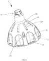
- FIG. 1 to FIG. 3illustrate an illuminator device 100 provided by the embodiment of the present disclosure, which is a high-power light bulb.
- the illuminator device 100includes a housing 1, a heat dissipation member 2 provided at an end of the housing 1, a light source module 5 configured to include an end in thermal contact with the heat dissipation member 2, an optical member 6 provided at another end of the light source module 5, an encloser 7 connected with the light source module 5 and configured to position the optical member 6 at the end of the light source module 5, a lamp holder 3 connected to another end of the housing 1, and a driving power supply module 4 accommodated into the housing 1 and electrically connected with the light source module 5.
- the light source module 5 and the housing 1are respectively provided at two ends of the heat dissipation member 2.
- the heat dissipation member 2is in thermal contact with the light source module 5, so that the heat emitted by the light source module 5 can be transferred to the heat dissipation member 2 and then be dissipated to the outside of the illuminator device 100 through the heat dissipation member 2.
- the heat transfer mediummay be air or other heat-conducting materials.
- a plurality of channels 8 communicating the inside of the illuminator device 100 with the outside of the illuminator device 100are provided in the illuminator device 100.
- each channel 8penetrates through the housing 1, the heat dissipation member 2 and the encloser 7.
- the channels 8can realize the convection between the air outside the illuminator device 100 and the air inside the illuminator device 100.
- the illuminator device 100may be a high-power LED lamp for indoor lighting, which may be mounted on a mounting base such as a ceiling.
- the lamp holder 3is electrically connected with the internal driving power supply module so as to electrically connect the illuminator device 100 to the commercial power.
- the housing 1is in the shape of a cap and is formed in a one-piece form by an insulating material.
- the housing 1is provided with a plurality of first through grooves 11 and a plurality of second through grooves 12.
- the housing 1is provided therein with a plurality of first positioning columns 13 connected with the heat dissipation member 2 and a plurality of second positioning columns 14 for supporting the light source module 5.
- a horizontal end faceis provided at an end of the housing 1 and bonded to an end of the heat dissipation member 2.
- the horizontal end face of the housing 1may be defined to be a first end face 15 of the housing 1.
- Another end of the housing 1is connected with the lamp holder 3; an outer surface of another end of the housing 1 is provided with screw threads; and the lamp holder 3 may be in threaded connection with the another end of the housing 1.
- the first through grooves 11extend to an outer surface of a side wall of the housing 1 from the first end face 15 of the housing 1.
- the first through groove 11is communicated with at least one channel 8 and includes a first port 111 and a first groove 112 which are communicated with each other.
- the first port 111is provided at the first end face 15.
- the first groove 112is formed by denting the outer surface of the side wall.
- the second through grooves 12penetrate through an inner surface and the outer surface of the side wall of the housing 1.
- the second through groove 12is communicated with at least one channel 8.
- the second through groove 12includes two second ports 121 and one second groove 122, in which the second ports 121 penetrate through the inner surface and the outer surface of the side wall of the housing 1; the second groove 122 is formed by denting the outer surface of the side wall; and the two second ports 121 are respectively formed on two sides of the second groove 122.
- the second through grooves 12further enhance the communication between the inner space of the housing 1 and the outer space of the illuminator device 100.
- Other embodimentsmay also adopt the form of only arranging the first through grooves or the second through grooves.
- a plurality of first positioning columns 13are formed inside the housing 1; a top surface of the first positioning column 13 is flush with the first end face 15; and a first positioning hole 131 which extends from the top surface of the first positioning column 13 to the outer surface of the housing 1 is formed in the first positioning column 13.
- a plurality of second positioning columns 14are provided inside the housing 1; a top surface of the second positioning column 14 is lower than the first end face 15; and the top surfaces of the plurality of second positioning columns 14 form a receiving surface for placing the driving power supply module 4 together.
- Second positioning holes 141are formed in the second positioning columns 14 respectively.
- the heat dissipation member 2is toroidal columnar and made of a metallic material with good thermal conductivity such as aluminum, and the outside diameter of the heat dissipation member 2 is flush with the outside diameter of the housing 1.
- the heat dissipation member 2includes a first end (not signed) and a second end (not signed) arranged in an upper-lower direction, the fist end of the heat dissipation member 2 is fixedly connected with the light source module 5, and the second end of the heat dissipation member 2 is fixedly connected with the hosing 1.
- the heat dissipation member 2includes a round inner ring 21, a round outer ring 22, and a plurality of connecting parts 23 extending along a radial direction and connecting the inner ring 21 and the outer ring 22.
- the inner ring 21 and the outer ring 22are concentrically arranged, and the plurality of connecting parts 23 extend along a vertical direction and uniformly distributed between the inner ring 21 and the outer ring 22.
- the shape of the connecting part 23is not limited to be a linear plate, or may also be curved, etc.
- a plurality of pipes 24 extending longitudinallyare formed in the heat dissipation member 2.
- the pipes 24are formed due to enclosure of the inner ring 21, the outer ring 22 and the connecting parts 23.
- the connecting parts 23are provided with a plurality of vertical third positioning holes 231 and vertical fourth positioning holes 232, in which the third positioning holes 231 correspond to the first positioning holes 131.
- the illuminator device 100further includes a plurality of first screws 16.
- the first screws 16penetrate through the first positioning holes 131 of the first positioning columns 13 and are accommodated into the third positioning holes 231 to realize the fixed connection between the housing 1 and the heat dissipation member 2.
- the wall surfaces of the plurality of pipes 24 of the heat dissipation member 2are provided with a plurality of vertical protruding strips 25.
- the protruding strips 25are configured to increase the internal surface area of the heat dissipation member 2 and enhance the heat dissipation effect.
- Other embodimentsmay also adopt other connecting means such as bonding connection, fastener connection or welding connection.
- the heat dissipation member 2is made of aluminum profile.
- the heat dissipation member with required lengthis cut from an aluminum profile matrix with corresponding diameter according to different lamp powers, luminous fluxes and photoelectric parameters.
- the powersmay range from tens of watts to hundreds of watts, and the luminous fluxes may range from hundreds of lumens to tens of thousands of lumens.
- the traditional high-power light sourcessuch as high-power fluorescent lamps and high-power metal halide lamps can be well replaced.
- one set of aluminum profile moldcan obtain a plurality of illuminator devices provided by the embodiment of the disclosure with different powers, so the production cost can be greatly reduced.
- the light source module 5includes a second substrate 51, a light source 52 provided on a side of the second substrate 51, and a heat homogenization plate 53 provided on another side of the second substrate 51.
- the heat homogenization plate 53is in thermal contact with the heat dissipation member 2, and emergent light from the light source 52 is emitted at least after light homogenization or light distribution by the optical member 6.
- the light sourceadopts a light-emitting diode (LED) light source and is annularly arranged, the light source may be provided to be an annular LED light source, or the light source may be provided to include a plurality of concentric annular LED light sources. In other embodiments, the light source may adopt TL light sources or other light sources.
- the second substrate 51may be a printed circuit board, and the second substrate 51 is provided with a plurality of fifth positioning holes 511.
- the heat homogenization plate 53is a vacuum cavity having a fine structure at an inner wall, is made of metal with good thermal conductivity such as copper, and is configured to enhance heat dissipation.
- a surface of the heat homogenization plate 53is provided with a plurality of sixth positioning holes 531, and the circumference of the heat homogenization plate 53 is further provided with a plurality of seventh positioning holes 532 and a plurality of clamping grooves 533.
- the illuminator device 100further includes a plurality of second screws 54.
- the second screws 54penetrate through the fifth positioning holes 511 and the sixth positioning holes 531 and are accommodated into the fourth positioning holes 232 to realize the fixed connection between the light source module 5 and the heat dissipation member 2. Moreover, the light source module 5 is bonded to the first end (not signed) of the heat dissipation member 2. In other embodiments, other connecting means such as bonding connection, fastener connection or welding connection may also be adopted.
- the driving power supply module 4includes a plurality of elements, including but not limited to an LED driving controller chip, a rectifying chip, a resistor, a capacitor, a fuse wire and a coil, which are all mounted on the first substrate 41 of the driving power supply module 4; through holes 411 corresponding to four second positioning columns 14 are formed at the first substrate 41; and the first substrate 41 is provided on a receiving surface in the housing 1, formed by the four second positioning columns 14.
- the illuminator device 100further includes four third screws 42. The third screws 42 penetrate through the through holes 411 and are accommodated into the second positioning columns 14 to fix the first substrate 41 in the housing 1.
- the driving power supply module 4 and the light source module 5may also be provided in a one-piece form; and the driving power supply module 4 and the light source module 5 may be provided on the same surface or different surfaces of the substrate.
- the optical member 6adopts a bubble cap, is formed in a one-piece form by an insulating material such as plastic, and is semispherical.
- the optical member 6includes a light-transmissive part 61 taken as a central part and protruded out of an upper surface of the encloser 7, and a horizontal edge part 62 extending to the outside from a side of the light-transmissive part 61.
- the second substrate 51 of the light source module 5abuts against the heat dissipation member 2 through the edge part 62; and a plurality of notches (not shown in the figures) are formed at the edge part 62 of the light-transmissive part 61.
- a TIR lens, a COB lens, a bulb-cap type light homogenizing shade, or a combination of a lens and a bulb capmay also be taken as the optical member; and as for the annular light source, the optical member may also be correspondingly set to be annular.
- the encloser 7is in the shape of a circular ring and is arranged around the edge part 62 of the optical member 6.
- the encloser 7includes a horizontal part 71 and a first vertical part 72 and a second vertical part 73 which are provided on two sides of the horizontal part 71 respectively.
- the outside diameter of the encloser 7is flush with the outside diameter of the heat dissipation member 2.
- a plurality of positioning columns 721 and elastic clamping arms 722are provided at the first vertical part 72. The positioning columns 721 may cooperate with the seventh positioning holes 532 at the heat homogenization plate 53.
- the elastic clamping arms 722penetrate through the plurality of notches (not shown in the figure) of the edge part 62 and the clamping grooves 533 formed at the edge of the heat homogenization plate 53, and are clamped into the edge of the heat homogenization plate 53.
- a plurality of first openings 711are formed at the horizontal part 71.
- the first openings 711are aligned with the first through grooves 11 in an upper-lower direction.
- the pipes 24are respectively communicated with the first through grooves 11 and the first openings 711.
- the first openings 711, the pipes 24 and the first through holes 11form the channels 8.
- the airflow from the outside of the illuminator device 100enters the first openings 711, penetrates through the channels 8 and then the pipes 24 of the heat dissipation member 2, and is discharged from the first ports 112 and the second ports 122 of the housing 1, so as to form internal and external convection and achieve effective heat dissipation.
- the enclosermay be removed; the structure of the optical member is adjusted and designed to be flush with the outside diameter of the heat dissipation member 2 and be fixedly connected with the heat dissipation member 2; and the optical member is provided with a structure taken as one part of the channel for heat dissipation.
- the illuminator device 100provided by the embodiments of the present disclosure is provided with a plurality of channels communicating the inside of the illuminator device 100 with the outside of the illuminator device 100; and the channels may be utilized to realize the convection between the air outside the illuminator device 100 and the air inside the illuminator device 100.
- the flow of the heat dissipation airflowis divided into at least two parts: one path aligned in the upper-lower direction has a rapid first flow rate; and the other path diffused into the large-size pipes 24 has a second flow rate, the second flow rate is lower than the first flow rate, and the path of airflow can fully exchange heat with the inner walls of the pipes 24.
- the heat emitted by the light source module 5 in the illuminator device 100can be effectively and rapidly dissipated through the channels 8. Therefore, the illuminator device 100 has good heat dissipation effect, and then the service life of the light source module 5 in the illuminator device 100 can be prolonged.
- the heat dissipation member 2has simple structure and light weight, so the weight of the entire illuminator device 100 is reduced and the light source module 5 may be replaced without the need of the additional installation of a safety chain, so that the illuminator device 100 is easy to assemble and disassemble.
Landscapes
- Engineering & Computer Science (AREA)
- General Engineering & Computer Science (AREA)
- Physics & Mathematics (AREA)
- Microelectronics & Electronic Packaging (AREA)
- Optics & Photonics (AREA)
- Arrangement Of Elements, Cooling, Sealing, Or The Like Of Lighting Devices (AREA)
- Non-Portable Lighting Devices Or Systems Thereof (AREA)
Description
- The present disclosure belongs to the field of semiconductor illumination technology, and in particular relates to an illuminator device.
- After a lamp, especially a high-power lamp, is illuminated and used for a long time, the temperature of the entire lamp will be high, and the service life of the lamp will be greatly shortened if the lamp cannot effectively dissipate heat. Therefore, the high-power lamp is generally provided with a heat dissipation structure between a lamp housing and an encloser. Most of current heat dissipation structures are made of aluminum alloy and provided with a plurality of fins which are closely arranged, so the structure is complex. Thus, the entire lamp has large weight, which exceeds the weight that a lamp holder (e.g., the standard lamp holder E27 or E40) of the lamp can bear. Therefore, the illuminator device also needs to be additionally equipped with a safety chain. The safety chain is connected between a mounting bracket and a light source, thus not only increasing the cost of the high-power lamp but also being inconvenient to replace the light source.
CN 203 023 858 U relates to a heat dissipation type light-emitting diode (LED) lamp comprising a snap ring, a heat dissipating component, cooling fins, a copper substrate, an LED light source and a transparent cover, the heat dissipating component is in a ring shape, the snap ring is attached to one end of the heat dissipating component, the cooling fins are covered at the other end of the heat dissipating component, the copper substrate is attached to the cooling fins, the LED light source is mounted on the copper substrate, the transparent cover is covered on the LED light source and mounted on the heat dissipating component, and cooling air flow channels which enable airflow inside the LED light source and outside the LED source to form convective flow are correspondingly arranged in the snap ring and the heat dissipating component.CN 102 434 804 A relates to a lighting lamp, in particular to an LED (Light-emitting Diode) tubing lamp with an inner runner radiator. In the LED lighting lamp, passages which are axially penetrated through the air flow are uniformly distributed at the periphery of the radiator.CN 101 813 242 A relates to a high efficient luminophor comprising a connection part, a heat radiator, a luminescent part, a central ventilation part and a transparent shell, wherein the connection part is provided with a wind-guiding part, a wind-guiding chamber and ventilation holes; the luminescent part is provided with a plurality of light-emitting diodes on the working surface of the heat radiator, and the working surface is arranged between an inner channel and an outer channel of the heat radiator; the central ventilated part is communicated with the inner channel by using a central channel of the central ventilation part, and the second end of the central ventilation part is located in the transparent shell, thereby an inner airflow channel is formed in air holes and the central channel of the central ventilation part through the inner channel, the wind-guiding chamber and the ventilation holes, and an outer airflow channel is formed in air holes and the periphery of the second end of the central ventilation part through the outer channel, the wind-guiding chamber and the ventilation holes.EP 2 320 133 A2
a light source disposed on a part of the heat radiating body; and an outer case being spaced apart from an outer surface of the heat radiating body and surrounding the heat radiating body.CN 204 629 144 U discloses an air convection style LED lights. The LED lights include a holding substrate formed by connecting a lamp shade and a lamp stand, a power strip and a heat dissipation ring; the lamp stand comprises a locating slot corresponding to the shape of the power strip, and the heat dissipation ring is fixed in the locating slot so as to form a heat dissipation chamber therebetween; the heat dissipation chamber comprises a plurality of first heat dissipation holes, the locating slot correspondingly comprises a plurality of second heat dissipation holes that communicate with the first heat dissipation holes and the surface of the lamp stand is equipped with a plurality of heat dissipation holes communicating with the second heat dissipation holes.CN 102 374 427 A discloses an LED (light-emitting diode) bulb lamp which comprises a standard lamp holder, a lamp body, a bulb and an LED lamp bank, wherein the LED lamp bank is arranged in the lamp body, the bulb is arranged at the front end of the lamp body and covers the LED lamp bank, wherein the LED lamp bank comprises an aluminum base and a plurality of LED lamps and a driving power supply arranged on the aluminum base, the lamp body comprises an upper body connected with the standard lamp body and a cooling cover connected between the bulb and the upper body, and a plurality of cooling air channels are evenly distributed in circumferential direction on the cooling cover.CN 204 437 777 U relates to a lamp and discloses an LED (Light-Emitting Diode) full optical angle floodlight. The LED full optical angle floodlight comprises a hollow housing and an LED fixed frame and an LED lamp panel which are fixedly arranged in the housing; the LED lamp panel is laterally arranged on the peripheral wall of the LED fixed frame; in addition, a power supply board, a radiator and a heat pipe are also arranged in the housing, wherein one end of the heat pipe is inserted in the LED fixed frame and is in contact with the LED fixed frame, the other end of the heat pipe is accommodated in the radiator and is in contact with the radiator and meanwhile, the power supply board is arranged at one side of the radiator and is electrically connected with the LED lamp panel.- In order to solve the above problem, the present disclosure provides an illuminator device with good heat dissipation effect.
- To achieve the above object, the present disclosure provides an illuminator device following
independent claim 1 which includes a housing, a heat dissipation member provided at an end of the housing, a light source module configured to include an end in thermal contact with the heat dissipation member, an optical member provided at another end of the light source module, and a driving power supply module electrically connected with the light source module, the light source module and the housing are respectively provided at two ends of the heat dissipation member, a plurality of channels communicating inside of the illuminator device with outside of the illuminator device are provided in the illuminator device, and the plurality of channels penetrate through the housing and the heat dissipation member. - Further, the illuminator device further includes an encloser which positions the optical member at the another end of the light source module.
- Further, the housing is formed with a plurality of first through grooves; a plurality of pipes are formed in the heat dissipation member; the encloser is provided with a plurality of first openings; the plurality of pipes are respectively communicated with the plurality of first through grooves and the plurality of first openings; and the plurality of first through grooves, the plurality of pipes and the plurality of first openings form the plurality of channels.
- Further, each of the first through grooves includes a first port and a first groove which are communicated with each other; the first port is provided at the first end face and communicated with at least one of the plurality of pipes; and the first groove is formed by denting the outer surface of the side wall.
- Further, the housing is formed with a plurality of second through grooves; and the plurality of second through grooves penetrate through both an inner surface and the outer surface of the side wall of the housing.
- Further, each of the second through grooves includes at least one second port and a second groove which are communicated with each other; the at least one second port penetrates through the inner surface and the outer surface of the side wall of the housing and is communicated with at least one of the plurality of pipes; and the second groove is formed by denting the outer surface of the side wall.
- Further, the heat dissipation member is toroidal columnar and includes an inner ring, an outer ring and a plurality of connecting plates connecting the inner ring and the outer ring; and the plurality of pipes are formed by enclosure of the inner ring, the outer ring and the plurality of connecting plates.
- Further, the light source module includes a substrate and a light source provided on a side of the substrate; and emergent light from the light source is emitted at least after light homogenization or light distribution by the optical member.
- Further, the light source is annularly arranged.
- Further, the illuminator device further includes a heat homogenization plate which is provided on another side of the substrate and is in thermal contact with the heat dissipation member.
- Further, the light source module and the driving power supply module are separately provided; and the driving power supply module is fixed in the housing.
- Further, the light source module and the driving power supply module are provided in a one-piece form.
- Further, the optical member includes an edge part and a central part; the encloser is provided around the edge part of the optical member; and the central part of the optical member is protruded out of an upper surface of the encloser.
- Further, the encloser is combined with the heat homogenization plate.
- Further, the heat dissipation member includes a first end and a second end arranged in an upper-lower direction; and the housing is fixedly connected with the second end of the heat dissipation member and bonded to the second end.
- Further, the heat dissipation member includes a first end and a second end arranged in an upper-lower direction; and the light source module is fixedly connected with the first end of the heat dissipation member and bonded to the first end.
- Further, the illuminator device further includes a lamp holder which is electrically connected with the driving power supply module and configured to electrically connect the illuminator device to an external power supply.
- The advantages of the present disclosure are:
Compared with the prior art, in the illuminator device provided by the embodiments of the present disclosure, by utilization of an external heat dissipation member and the arrangement of a plurality of channels communicating the inside of the illuminator device with the outside of the illuminator device, the convection between the air outside the illuminator device and the air inside the illuminator device can be realized by utilization of the channels. Thus, the heat emitted by the light source module in the illuminator device can be effectively and rapidly dissipated through the channels. Therefore, the illuminator device has good heat dissipation effect, and then the service life of the light source module in the illuminator device is prolonged. - The foregoing is only the brief description of the technical solutions of the present disclosure. Implementation may be made according to the content of the description for more clear understanding of the technical means of the present disclosure. Moreover, the preferred embodiments of the present disclosure will be given below for more obvious and easy understanding of the above and other objectives, characteristics and advantages of the present disclosure.
- The accompanying drawings illustrated here are only provided for further understanding of the present disclosure and constitute one part of the present disclosure. The exemplary embodiments of the present disclosure and the description thereof are used for explaining the present disclosure and do not constitute an improper limitation of the present disclosure. In the accompanying drawings:
FIG. 1 is a schematic three-dimensional assembly view of an illuminator device provided by a preferred embodiment of the present disclosure;FIG. 2 is a schematic exploded view ofFIG. 1 ;FIG. 3 is a schematic exploded view ofFIG. 1 from another viewpoint;FIG. 4 is a schematic view of a housing in the illuminator device provided by the preferred embodiment of the present disclosure;FIG. 5 is a schematic view of the housing inFIG. 4 from another viewpoint;FIG. 6 is a schematic view of the housing inFIG. 4 from still another viewpoint;FIG. 7 is a schematic view of a heat dissipation member in the illuminator device provided by the preferred embodiment of the present disclosure; andFIG. 8 is a schematic sectional view along the A-A line inFIG. 1 .- In order to make objects, technical details and advantages of the embodiments of the disclosure apparent, the technical solutions of the embodiments will be described in a clearly and fully understandable way in connection with the embodiments of the disclosure and related drawings. Apparently, the described embodiments are just a part but not all of the embodiments of the disclosure. Based on the described embodiments herein, those skilled in the art can obtain other embodiment(s), without any inventive work, which should be within the scope of the disclosure.
FIG. 1 to FIG. 3 illustrate anilluminator device 100 provided by the embodiment of the present disclosure, which is a high-power light bulb. Theilluminator device 100 includes ahousing 1, aheat dissipation member 2 provided at an end of thehousing 1, alight source module 5 configured to include an end in thermal contact with theheat dissipation member 2, anoptical member 6 provided at another end of thelight source module 5, an encloser 7 connected with thelight source module 5 and configured to position theoptical member 6 at the end of thelight source module 5, a lamp holder 3 connected to another end of thehousing 1, and a driving power supply module 4 accommodated into thehousing 1 and electrically connected with thelight source module 5. In theilluminator device 100, thelight source module 5 and thehousing 1 are respectively provided at two ends of theheat dissipation member 2. Theheat dissipation member 2 is in thermal contact with thelight source module 5, so that the heat emitted by thelight source module 5 can be transferred to theheat dissipation member 2 and then be dissipated to the outside of theilluminator device 100 through theheat dissipation member 2. The heat transfer medium may be air or other heat-conducting materials.- As shown in
FIG. 8 , a plurality of channels 8 communicating the inside of theilluminator device 100 with the outside of theilluminator device 100 are provided in theilluminator device 100. In theilluminator device 100, each channel 8 penetrates through thehousing 1, theheat dissipation member 2 and the encloser 7. The channels 8 can realize the convection between the air outside theilluminator device 100 and the air inside theilluminator device 100. Theilluminator device 100 may be a high-power LED lamp for indoor lighting, which may be mounted on a mounting base such as a ceiling. The lamp holder 3 is electrically connected with the internal driving power supply module so as to electrically connect theilluminator device 100 to the commercial power. - Detailed description will be given below to the components and the connecting relationships between the components in the
illuminator device 100, provided by the embodiment of the present disclosure. - As shown in
FIG. 2 ,FIG. 4 andFIG. 5 , thehousing 1 is in the shape of a cap and is formed in a one-piece form by an insulating material. Thehousing 1 is provided with a plurality of first throughgrooves 11 and a plurality of second throughgrooves 12. Thehousing 1 is provided therein with a plurality offirst positioning columns 13 connected with theheat dissipation member 2 and a plurality ofsecond positioning columns 14 for supporting thelight source module 5. A horizontal end face is provided at an end of thehousing 1 and bonded to an end of theheat dissipation member 2. The horizontal end face of thehousing 1 may be defined to be afirst end face 15 of thehousing 1. Another end of thehousing 1 is connected with the lamp holder 3; an outer surface of another end of thehousing 1 is provided with screw threads; and the lamp holder 3 may be in threaded connection with the another end of thehousing 1. - Specifically, the first through
grooves 11 extend to an outer surface of a side wall of thehousing 1 from thefirst end face 15 of thehousing 1. The first throughgroove 11 is communicated with at least one channel 8 and includes afirst port 111 and afirst groove 112 which are communicated with each other. Thefirst port 111 is provided at thefirst end face 15. Thefirst groove 112 is formed by denting the outer surface of the side wall. By adoption of the first throughgrooves 11, the inner space of thehousing 1 may be communicated with the outside of theilluminator device 100. - Specifically, the second through
grooves 12 penetrate through an inner surface and the outer surface of the side wall of thehousing 1. The second throughgroove 12 is communicated with at least one channel 8. The second throughgroove 12 includes twosecond ports 121 and onesecond groove 122, in which thesecond ports 121 penetrate through the inner surface and the outer surface of the side wall of thehousing 1; thesecond groove 122 is formed by denting the outer surface of the side wall; and the twosecond ports 121 are respectively formed on two sides of thesecond groove 122. The second throughgrooves 12 further enhance the communication between the inner space of thehousing 1 and the outer space of theilluminator device 100. Other embodiments may also adopt the form of only arranging the first through grooves or the second through grooves. - As shown in
FIG. 4 , a plurality offirst positioning columns 13 are formed inside thehousing 1; a top surface of thefirst positioning column 13 is flush with thefirst end face 15; and afirst positioning hole 131 which extends from the top surface of thefirst positioning column 13 to the outer surface of thehousing 1 is formed in thefirst positioning column 13. With reference toFIG. 5 andFIG. 8 , a plurality ofsecond positioning columns 14 are provided inside thehousing 1; a top surface of thesecond positioning column 14 is lower than thefirst end face 15; and the top surfaces of the plurality ofsecond positioning columns 14 form a receiving surface for placing the driving power supply module 4 together. Second positioning holes 141 are formed in thesecond positioning columns 14 respectively. - As shown in
FIG. 3 andFIG. 7 , theheat dissipation member 2 is toroidal columnar and made of a metallic material with good thermal conductivity such as aluminum, and the outside diameter of theheat dissipation member 2 is flush with the outside diameter of thehousing 1. Theheat dissipation member 2 includes a first end (not signed) and a second end (not signed) arranged in an upper-lower direction, the fist end of theheat dissipation member 2 is fixedly connected with thelight source module 5, and the second end of theheat dissipation member 2 is fixedly connected with thehosing 1. Theheat dissipation member 2 includes a roundinner ring 21, a roundouter ring 22, and a plurality of connectingparts 23 extending along a radial direction and connecting theinner ring 21 and theouter ring 22. Specifically, theinner ring 21 and theouter ring 22 are concentrically arranged, and the plurality of connectingparts 23 extend along a vertical direction and uniformly distributed between theinner ring 21 and theouter ring 22. The shape of the connectingpart 23 is not limited to be a linear plate, or may also be curved, etc. By adoption of the above design, a plurality ofpipes 24 extending longitudinally are formed in theheat dissipation member 2. Thepipes 24 are formed due to enclosure of theinner ring 21, theouter ring 22 and the connectingparts 23. Moreover, the connectingparts 23 are provided with a plurality of vertical third positioning holes 231 and vertical fourth positioning holes 232, in which the third positioning holes 231 correspond to the first positioning holes 131. - As shown in
FIG. 2 ,FIG. 3 ,FIG. 4 andFIG. 7 , theilluminator device 100 further includes a plurality of first screws 16. The first screws 16 penetrate through the first positioning holes 131 of thefirst positioning columns 13 and are accommodated into the third positioning holes 231 to realize the fixed connection between thehousing 1 and theheat dissipation member 2. The wall surfaces of the plurality ofpipes 24 of theheat dissipation member 2 are provided with a plurality of vertical protruding strips 25. The protruding strips 25 are configured to increase the internal surface area of theheat dissipation member 2 and enhance the heat dissipation effect. Other embodiments may also adopt other connecting means such as bonding connection, fastener connection or welding connection. - According to the invention, the
heat dissipation member 2 is made of aluminum profile. The heat dissipation member with required length is cut from an aluminum profile matrix with corresponding diameter according to different lamp powers, luminous fluxes and photoelectric parameters. The powers may range from tens of watts to hundreds of watts, and the luminous fluxes may range from hundreds of lumens to tens of thousands of lumens. The traditional high-power light sources such as high-power fluorescent lamps and high-power metal halide lamps can be well replaced. Meanwhile, one set of aluminum profile mold can obtain a plurality of illuminator devices provided by the embodiment of the disclosure with different powers, so the production cost can be greatly reduced. - As shown in
FIG. 2 andFIG. 3 , thelight source module 5 includes asecond substrate 51, alight source 52 provided on a side of thesecond substrate 51, and aheat homogenization plate 53 provided on another side of thesecond substrate 51. Theheat homogenization plate 53 is in thermal contact with theheat dissipation member 2, and emergent light from thelight source 52 is emitted at least after light homogenization or light distribution by theoptical member 6. In the embodiment of the present disclosure, the light source adopts a light-emitting diode (LED) light source and is annularly arranged, the light source may be provided to be an annular LED light source, or the light source may be provided to include a plurality of concentric annular LED light sources. In other embodiments, the light source may adopt TL light sources or other light sources. - The
second substrate 51 may be a printed circuit board, and thesecond substrate 51 is provided with a plurality of fifth positioning holes 511. Theheat homogenization plate 53 is a vacuum cavity having a fine structure at an inner wall, is made of metal with good thermal conductivity such as copper, and is configured to enhance heat dissipation. A surface of theheat homogenization plate 53 is provided with a plurality of sixth positioning holes 531, and the circumference of theheat homogenization plate 53 is further provided with a plurality of seventh positioning holes 532 and a plurality of clampinggrooves 533. Theilluminator device 100 further includes a plurality of second screws 54. The second screws 54 penetrate through the fifth positioning holes 511 and the sixth positioning holes 531 and are accommodated into the fourth positioning holes 232 to realize the fixed connection between thelight source module 5 and theheat dissipation member 2. Moreover, thelight source module 5 is bonded to the first end (not signed) of theheat dissipation member 2. In other embodiments, other connecting means such as bonding connection, fastener connection or welding connection may also be adopted. - As shown in
FIG. 2 andFIG. 8 , the driving power supply module 4 includes a plurality of elements, including but not limited to an LED driving controller chip, a rectifying chip, a resistor, a capacitor, a fuse wire and a coil, which are all mounted on thefirst substrate 41 of the driving power supply module 4; through holes 411 corresponding to foursecond positioning columns 14 are formed at thefirst substrate 41; and thefirst substrate 41 is provided on a receiving surface in thehousing 1, formed by the foursecond positioning columns 14. Theilluminator device 100 further includes fourthird screws 42. The third screws 42 penetrate through the through holes 411 and are accommodated into thesecond positioning columns 14 to fix thefirst substrate 41 in thehousing 1. In other embodiments, the driving power supply module 4 and thelight source module 5 may also be provided in a one-piece form; and the driving power supply module 4 and thelight source module 5 may be provided on the same surface or different surfaces of the substrate. - As shown in
FIG. 2 andFIG. 3 , in the embodiment of the present disclosure, theoptical member 6 adopts a bubble cap, is formed in a one-piece form by an insulating material such as plastic, and is semispherical. Theoptical member 6 includes a light-transmissive part 61 taken as a central part and protruded out of an upper surface of the encloser 7, and ahorizontal edge part 62 extending to the outside from a side of the light-transmissive part 61. In the embodiment of the present disclosure, thesecond substrate 51 of thelight source module 5 abuts against theheat dissipation member 2 through theedge part 62; and a plurality of notches (not shown in the figures) are formed at theedge part 62 of the light-transmissive part 61. In other embodiments, a TIR lens, a COB lens, a bulb-cap type light homogenizing shade, or a combination of a lens and a bulb cap may also be taken as the optical member; and as for the annular light source, the optical member may also be correspondingly set to be annular. - As shown in
FIG. 2 ,FIG. 3 ,FIG. 4 andFIG. 8 , the encloser 7 is in the shape of a circular ring and is arranged around theedge part 62 of theoptical member 6. The encloser 7 includes ahorizontal part 71 and a firstvertical part 72 and a secondvertical part 73 which are provided on two sides of thehorizontal part 71 respectively. The outside diameter of the encloser 7 is flush with the outside diameter of theheat dissipation member 2. A plurality ofpositioning columns 721 and elastic clampingarms 722 are provided at the firstvertical part 72. Thepositioning columns 721 may cooperate with the seventh positioning holes 532 at theheat homogenization plate 53. Theelastic clamping arms 722 penetrate through the plurality of notches (not shown in the figure) of theedge part 62 and the clampinggrooves 533 formed at the edge of theheat homogenization plate 53, and are clamped into the edge of theheat homogenization plate 53. Thus, the combination of the encloser 7 and theheat homogenization plate 53 is realized, so the fixed connection between the encloser 7 and thelight source module 5 can be realized. A plurality offirst openings 711 are formed at thehorizontal part 71. Thefirst openings 711 are aligned with the first throughgrooves 11 in an upper-lower direction. Thepipes 24 are respectively communicated with the first throughgrooves 11 and thefirst openings 711. Thefirst openings 711, thepipes 24 and the first throughholes 11 form the channels 8. The airflow from the outside of theilluminator device 100 enters thefirst openings 711, penetrates through the channels 8 and then thepipes 24 of theheat dissipation member 2, and is discharged from thefirst ports 112 and thesecond ports 122 of thehousing 1, so as to form internal and external convection and achieve effective heat dissipation. In other embodiments, the encloser may be removed; the structure of the optical member is adjusted and designed to be flush with the outside diameter of theheat dissipation member 2 and be fixedly connected with theheat dissipation member 2; and the optical member is provided with a structure taken as one part of the channel for heat dissipation. - In summary, the
illuminator device 100 provided by the embodiments of the present disclosure is provided with a plurality of channels communicating the inside of theilluminator device 100 with the outside of theilluminator device 100; and the channels may be utilized to realize the convection between the air outside theilluminator device 100 and the air inside theilluminator device 100. - With reference to
FIG. 7 andFIG. 8 , the flow of the heat dissipation airflow is divided into at least two parts: one path aligned in the upper-lower direction has a rapid first flow rate; and the other path diffused into the large-size pipes 24 has a second flow rate, the second flow rate is lower than the first flow rate, and the path of airflow can fully exchange heat with the inner walls of thepipes 24. Thus, the heat emitted by thelight source module 5 in theilluminator device 100 can be effectively and rapidly dissipated through the channels 8. Therefore, theilluminator device 100 has good heat dissipation effect, and then the service life of thelight source module 5 in theilluminator device 100 can be prolonged. On the other hand, theheat dissipation member 2 has simple structure and light weight, so the weight of theentire illuminator device 100 is reduced and thelight source module 5 may be replaced without the need of the additional installation of a safety chain, so that theilluminator device 100 is easy to assemble and disassemble. - The foregoing preferred embodiments are provided for further detailed description of the objectives, the technical solutions and the advantages of the present disclosure.
- In addition, it should be also noted that: the language used in the description is mainly selected for the purpose of readability and teaching, and is not selected for the purpose of explaining or limiting the subject of the present disclosure. Therefore, many modifications and variations will be apparent to those skilled in the art without departing from the scope of the disclosure. The disclosure of the present disclosure is illustrative and not restrictive as for the scope of the disclosure. The scope of the present disclosure shall be defined by the appended claims.
Claims (13)
- An illuminator device (100), comprising a housing (1), a heat dissipation member (2) provided at an end of the housing (1), a light source module (5) configured to comprise an end in thermal contact with the heat dissipation member (2), an optical member (6) provided at another end of the light source module (5), and a driving power supply module (4) electrically connected with the light source module (5), wherein the light source module (5) and the housing (1) are respectively provided at two ends of the heat dissipation member (2), a plurality of channels (8) communicating inside of the illuminator device (100) with outside of the illuminator device (110) are provided in the illuminator device (100), and the plurality of channels (8) penetrate through the housing (1) and the heat dissipation member (2),wherein the illuminator device (100) further comprises an encloser (7) which positions the optical member (6) at the another end of the light source module (5), andwherein the housing (1) is formed with a plurality of first through grooves (11); a plurality of pipes (24) are formed in the heat dissipation member (2); the encloser (7) is provided with a plurality of first openings (711); the plurality of pipes (24) are respectively communicated with the plurality of first through grooves (11) and the plurality of first openings (711); and the plurality of first through grooves (11), the plurality of pipes (24) and the plurality of first openings (711) form the plurality of channels (8)characterized in that
the heat dissipating member (2) is made of an aluminum profile. - The illuminator device (100) according to claim 1, wherein the housing (1) is provided with a first end face (15) in contact with an end of the heat dissipation member (2); and the plurality of first through grooves (11) extend to the outer surface of the side wall of the housing (1) from the first end face (15).
- The illuminator device (100) according to claim 2, wherein each of the first through grooves (11) comprises a first port (111) and a first groove (112) which are communicated with each other; the first port (111) is provided at the first end face (15) and communicated with at least one of the plurality of pipes (24); and the first groove (112) is formed by denting the outer surface of the side wall.
- The illuminator device (100) according to claim 3, wherein the housing (1) is formed with a plurality of second through grooves (12); and the plurality of second through grooves (12) penetrate through both the inner surface and the outer surface of the side wall of the housing (1).
- The illuminator device (100) according to claim 4, wherein each of the second through grooves (12) comprises at least one second port (121) and a second groove (122) which are communicated with each other; the at least one second port (121) penetrates through the inner surface and the outer surface of the side wall of the housing (1) and is communicated with at least one of the plurality of pipes (24); and the second groove (122) is formed by denting the outer surface of the side wall.
- The illuminator device (100) according to claim 1, wherein the heat dissipation member is toroidal columnar and comprises an inner ring (21), an outer ring (22) and a plurality of connecting parts (23) connecting the inner ring (21) and the outer ring; and the plurality of pipes (24) are formed by enclosure of the inner ring (21), the outer ring (22) and the plurality of connecting parts (23).
- The illuminator device (100) according to claim 1, wherein the light source module (5) comprises a substrate (51) and a light source (52) provided on a side of the substrate (51); and emergent light from the light source (52) is emitted at least after light homogenization or light distribution by the optical member (6) wherein preferably the light source (52) is annularly arranged.
- The illuminator device (100) according to claim 7, wherein the illuminator device (100) further comprises a heat homogenization plate (53) which is provided on another side of the substrate (51) and is in thermal contact with the heat dissipation member (2) and/or wherein the light source module (5) and the driving power supply module (4) are separately provided; and the driving power supply module (4) is fixed in the housing (1).
- The illuminator device (100) according to claim 1, wherein the light source module (5) and the driving power supply module (4) are provided in a one-piece form and/or wherein the optical member (6) comprises an edge part (62) and a central part (61); the encloser (7) is provided around the edge part (62) of the optical member (6); and the central part (61) of the optical member (6) is protruded out of an upper surface of the encloser (7).
- The illuminator device (100) according to claim 1, wherein the illuminator device (100) further comprises a heat homogenization plate (53); and the encloser (7) is combined with the heat homogenization plate (53).
- The illuminator device (100) according to claim 1, wherein the heat dissipation member (2) comprises a first end and a second end arranged in an upper-lower direction; and the housing (1) is fixedly connected with the second end of the heat dissipation member (2) and bonded to the second end.
- The illuminator device (100) according to claim 1, wherein the heat dissipation member (2) comprises a first end and a second end arranged in an upper-lower direction; and the light source module (5) is fixedly connected with the first end of the heat dissipation member (2) and bonded to the first end, wherein preferably the optical member (6) is a lens or a diffusion shade.
- The illuminator device (100) according to claim 1, wherein the illuminator device (100) further comprises a lamp holder (3) which is electrically connected with the driving power supply module (4) and configured to electrically connect the illuminator device (100) to an external power supply.
Applications Claiming Priority (2)
| Application Number | Priority Date | Filing Date | Title |
|---|---|---|---|
| CN201610463893.2ACN106051646B (en) | 2016-06-23 | 2016-06-23 | Lighting device |
| PCT/CN2017/083628WO2017219772A1 (en) | 2016-06-23 | 2017-05-09 | Lighting device |
Publications (3)
| Publication Number | Publication Date |
|---|---|
| EP3447374A1 EP3447374A1 (en) | 2019-02-27 |
| EP3447374A4 EP3447374A4 (en) | 2019-11-20 |
| EP3447374B1true EP3447374B1 (en) | 2021-12-15 |
Family
ID=57165508
Family Applications (1)
| Application Number | Title | Priority Date | Filing Date |
|---|---|---|---|
| EP17814510.8AActiveEP3447374B1 (en) | 2016-06-23 | 2017-05-09 | Lighting device |
Country Status (4)
| Country | Link |
|---|---|
| EP (1) | EP3447374B1 (en) |
| CN (1) | CN106051646B (en) |
| DE (1) | DE202017006973U1 (en) |
| WO (1) | WO2017219772A1 (en) |
Families Citing this family (2)
| Publication number | Priority date | Publication date | Assignee | Title |
|---|---|---|---|---|
| US10871282B2 (en) | 2016-06-23 | 2020-12-22 | Oppie Lighting Co., Ltd. | Illuminator device |
| CN106051646B (en)* | 2016-06-23 | 2023-07-28 | 欧普照明股份有限公司 | Lighting device |
Citations (1)
| Publication number | Priority date | Publication date | Assignee | Title |
|---|---|---|---|---|
| US20110037368A1 (en)* | 2009-08-14 | 2011-02-17 | Risun Expanse Corp. | Lamp structure |
Family Cites Families (19)
| Publication number | Priority date | Publication date | Assignee | Title |
|---|---|---|---|---|
| US7758223B2 (en)* | 2005-04-08 | 2010-07-20 | Toshiba Lighting & Technology Corporation | Lamp having outer shell to radiate heat of light source |
| CN201259106Y (en)* | 2008-07-07 | 2009-06-17 | 兆立光电有限公司 | LED lights |
| CN101813242B (en)* | 2009-02-23 | 2011-11-16 | 绿点高新科技股份有限公司 | high-efficiency illuminant |
| KR101081312B1 (en)* | 2009-11-09 | 2011-11-09 | 엘지이노텍 주식회사 | Lighting device |
| US8829771B2 (en)* | 2009-11-09 | 2014-09-09 | Lg Innotek Co., Ltd. | Lighting device |
| JP5600936B2 (en)* | 2009-12-29 | 2014-10-08 | 神保電器株式会社 | LED lighting device |
| CN202188328U (en)* | 2011-06-27 | 2012-04-11 | 南京汉德森科技股份有限公司 | LED lamp with high-efficiency heat radiation power supply assembly |
| CN102374427A (en)* | 2011-09-20 | 2012-03-14 | 浙江捷莱照明有限公司 | LED (light-emitting diode) bulb lamp |
| CN102434804A (en)* | 2011-12-16 | 2012-05-02 | 广东朗视光电技术有限公司 | Set the LED lighting lamp of the inner runner radiator |
| TW201326642A (en)* | 2011-12-23 | 2013-07-01 | Power Digital Delight Co Ltd | LED street lamp |
| CN103453335B (en)* | 2012-05-30 | 2016-01-20 | 深圳市万家照明有限公司 | A kind of lamp body and LED bulb |
| CN102966871B (en)* | 2012-08-02 | 2016-01-20 | 福建新文行灯饰有限公司 | A kind of radiating LED lamp |
| KR20150013053A (en)* | 2013-07-25 | 2015-02-04 | 서울반도체 주식회사 | LED illumination device |
| CN104806898A (en)* | 2014-01-25 | 2015-07-29 | 欧普照明股份有限公司 | LED (Light Emitting Diode) lamp |
| CN204127882U (en)* | 2014-09-25 | 2015-01-28 | 深圳市凯柏光电有限公司 | LED and lamp housing thereof |
| CN204437777U (en)* | 2015-01-30 | 2015-07-01 | 深圳市科纳实业有限公司 | The full optic angle floodlight of LED |
| CN204629144U (en)* | 2015-03-16 | 2015-09-09 | 陈忠 | Cross-ventilation radiating type LED lamp |
| CN106051646B (en)* | 2016-06-23 | 2023-07-28 | 欧普照明股份有限公司 | Lighting device |
| CN205806983U (en)* | 2016-06-23 | 2016-12-14 | 欧普照明股份有限公司 | Illuminator |
- 2016
- 2016-06-23CNCN201610463893.2Apatent/CN106051646B/enactiveActive
- 2017
- 2017-05-09DEDE202017006973.3Upatent/DE202017006973U1/enactiveActive
- 2017-05-09WOPCT/CN2017/083628patent/WO2017219772A1/ennot_activeCeased
- 2017-05-09EPEP17814510.8Apatent/EP3447374B1/enactiveActive
Patent Citations (1)
| Publication number | Priority date | Publication date | Assignee | Title |
|---|---|---|---|---|
| US20110037368A1 (en)* | 2009-08-14 | 2011-02-17 | Risun Expanse Corp. | Lamp structure |
Also Published As
| Publication number | Publication date |
|---|---|
| WO2017219772A1 (en) | 2017-12-28 |
| DE202017006973U1 (en) | 2019-01-21 |
| CN106051646A (en) | 2016-10-26 |
| EP3447374A1 (en) | 2019-02-27 |
| CN106051646B (en) | 2023-07-28 |
| EP3447374A4 (en) | 2019-11-20 |
Similar Documents
| Publication | Publication Date | Title |
|---|---|---|
| US7857486B2 (en) | LED lamp assembly having heat pipes and finned heat sinks | |
| US7695162B2 (en) | LED lamp having a plurality of heat sinks | |
| US7758214B2 (en) | LED lamp | |
| CN101457913B (en) | LED lamp | |
| US7847471B2 (en) | LED lamp | |
| US20110121707A1 (en) | Led bulb for replacing a halogen bulb in the form of reflective cup | |
| US10871282B2 (en) | Illuminator device | |
| TW201525357A (en) | LED light bulb with a bi-directional axle convection type heat sink structure | |
| TW201348646A (en) | Light emitting diode lamp | |
| WO2013044636A1 (en) | Led lamp | |
| CN102644866A (en) | LED (Light-Emitting Diode) lamp bulb with good heat radiation | |
| CN204785745U (en) | Ball bubble lamp | |
| CN107642697B (en) | Radiator for LED module, LED module and LED lamp | |
| CN212132068U (en) | lamps | |
| EP3447374B1 (en) | Lighting device | |
| CN101865379A (en) | LED lamps | |
| US20190128512A1 (en) | Lighting device | |
| WO2013107731A1 (en) | Illuminating device and luminaire having the illuminating device | |
| CN102853295B (en) | Down lamp capable of radiating heat through convection of inner channel and outer channel | |
| CN205806983U (en) | Illuminator | |
| EP3462077B1 (en) | Lighting device | |
| CN107642696B (en) | Radiator for LED module, LED module and LED lamp | |
| CN102494288B (en) | Light-emitting diode (LED) reflector lamp with fins capable of radiating heat | |
| CN213746653U (en) | A radiator and its lamp | |
| CN218237411U (en) | Radiator, radiating assembly and spotlight |
Legal Events
| Date | Code | Title | Description |
|---|---|---|---|
| STAA | Information on the status of an ep patent application or granted ep patent | Free format text:STATUS: THE INTERNATIONAL PUBLICATION HAS BEEN MADE | |
| PUAI | Public reference made under article 153(3) epc to a published international application that has entered the european phase | Free format text:ORIGINAL CODE: 0009012 | |
| STAA | Information on the status of an ep patent application or granted ep patent | Free format text:STATUS: REQUEST FOR EXAMINATION WAS MADE | |
| 17P | Request for examination filed | Effective date:20181123 | |
| AK | Designated contracting states | Kind code of ref document:A1 Designated state(s):AL AT BE BG CH CY CZ DE DK EE ES FI FR GB GR HR HU IE IS IT LI LT LU LV MC MK MT NL NO PL PT RO RS SE SI SK SM TR | |
| AX | Request for extension of the european patent | Extension state:BA ME | |
| DAV | Request for validation of the european patent (deleted) | ||
| DAX | Request for extension of the european patent (deleted) | ||
| A4 | Supplementary search report drawn up and despatched | Effective date:20191022 | |
| RIC1 | Information provided on ipc code assigned before grant | Ipc:F21V 29/83 20150101ALI20191016BHEP Ipc:F21K 9/237 20160101ALI20191016BHEP Ipc:F21V 29/503 20150101AFI20191016BHEP Ipc:F21V 29/70 20150101ALI20191016BHEP | |
| STAA | Information on the status of an ep patent application or granted ep patent | Free format text:STATUS: EXAMINATION IS IN PROGRESS | |
| 17Q | First examination report despatched | Effective date:20201102 | |
| GRAP | Despatch of communication of intention to grant a patent | Free format text:ORIGINAL CODE: EPIDOSNIGR1 | |
| STAA | Information on the status of an ep patent application or granted ep patent | Free format text:STATUS: GRANT OF PATENT IS INTENDED | |
| INTG | Intention to grant announced | Effective date:20210628 | |
| GRAS | Grant fee paid | Free format text:ORIGINAL CODE: EPIDOSNIGR3 | |
| GRAA | (expected) grant | Free format text:ORIGINAL CODE: 0009210 | |
| STAA | Information on the status of an ep patent application or granted ep patent | Free format text:STATUS: THE PATENT HAS BEEN GRANTED | |
| AK | Designated contracting states | Kind code of ref document:B1 Designated state(s):AL AT BE BG CH CY CZ DE DK EE ES FI FR GB GR HR HU IE IS IT LI LT LU LV MC MK MT NL NO PL PT RO RS SE SI SK SM TR | |
| REG | Reference to a national code | Ref country code:GB Ref legal event code:FG4D Ref country code:CH Ref legal event code:EP | |
| REG | Reference to a national code | Ref country code:DE Ref legal event code:R096 Ref document number:602017051042 Country of ref document:DE | |
| REG | Reference to a national code | Ref country code:IE Ref legal event code:FG4D | |
| REG | Reference to a national code | Ref country code:AT Ref legal event code:REF Ref document number:1455745 Country of ref document:AT Kind code of ref document:T Effective date:20220115 | |
| REG | Reference to a national code | Ref country code:NL Ref legal event code:FP | |
| REG | Reference to a national code | Ref country code:LT Ref legal event code:MG9D | |
| PG25 | Lapsed in a contracting state [announced via postgrant information from national office to epo] | Ref country code:RS Free format text:LAPSE BECAUSE OF FAILURE TO SUBMIT A TRANSLATION OF THE DESCRIPTION OR TO PAY THE FEE WITHIN THE PRESCRIBED TIME-LIMIT Effective date:20211215 Ref country code:LT Free format text:LAPSE BECAUSE OF FAILURE TO SUBMIT A TRANSLATION OF THE DESCRIPTION OR TO PAY THE FEE WITHIN THE PRESCRIBED TIME-LIMIT Effective date:20211215 Ref country code:FI Free format text:LAPSE BECAUSE OF FAILURE TO SUBMIT A TRANSLATION OF THE DESCRIPTION OR TO PAY THE FEE WITHIN THE PRESCRIBED TIME-LIMIT Effective date:20211215 Ref country code:BG Free format text:LAPSE BECAUSE OF FAILURE TO SUBMIT A TRANSLATION OF THE DESCRIPTION OR TO PAY THE FEE WITHIN THE PRESCRIBED TIME-LIMIT Effective date:20220315 | |
| REG | Reference to a national code | Ref country code:AT Ref legal event code:MK05 Ref document number:1455745 Country of ref document:AT Kind code of ref document:T Effective date:20211215 | |
| PG25 | Lapsed in a contracting state [announced via postgrant information from national office to epo] | Ref country code:SE Free format text:LAPSE BECAUSE OF FAILURE TO SUBMIT A TRANSLATION OF THE DESCRIPTION OR TO PAY THE FEE WITHIN THE PRESCRIBED TIME-LIMIT Effective date:20211215 Ref country code:NO Free format text:LAPSE BECAUSE OF FAILURE TO SUBMIT A TRANSLATION OF THE DESCRIPTION OR TO PAY THE FEE WITHIN THE PRESCRIBED TIME-LIMIT Effective date:20220315 Ref country code:LV Free format text:LAPSE BECAUSE OF FAILURE TO SUBMIT A TRANSLATION OF THE DESCRIPTION OR TO PAY THE FEE WITHIN THE PRESCRIBED TIME-LIMIT Effective date:20211215 Ref country code:HR Free format text:LAPSE BECAUSE OF FAILURE TO SUBMIT A TRANSLATION OF THE DESCRIPTION OR TO PAY THE FEE WITHIN THE PRESCRIBED TIME-LIMIT Effective date:20211215 Ref country code:GR Free format text:LAPSE BECAUSE OF FAILURE TO SUBMIT A TRANSLATION OF THE DESCRIPTION OR TO PAY THE FEE WITHIN THE PRESCRIBED TIME-LIMIT Effective date:20220316 | |
| PG25 | Lapsed in a contracting state [announced via postgrant information from national office to epo] | Ref country code:SM Free format text:LAPSE BECAUSE OF FAILURE TO SUBMIT A TRANSLATION OF THE DESCRIPTION OR TO PAY THE FEE WITHIN THE PRESCRIBED TIME-LIMIT Effective date:20211215 Ref country code:SK Free format text:LAPSE BECAUSE OF FAILURE TO SUBMIT A TRANSLATION OF THE DESCRIPTION OR TO PAY THE FEE WITHIN THE PRESCRIBED TIME-LIMIT Effective date:20211215 Ref country code:RO Free format text:LAPSE BECAUSE OF FAILURE TO SUBMIT A TRANSLATION OF THE DESCRIPTION OR TO PAY THE FEE WITHIN THE PRESCRIBED TIME-LIMIT Effective date:20211215 Ref country code:PT Free format text:LAPSE BECAUSE OF FAILURE TO SUBMIT A TRANSLATION OF THE DESCRIPTION OR TO PAY THE FEE WITHIN THE PRESCRIBED TIME-LIMIT Effective date:20220418 Ref country code:ES Free format text:LAPSE BECAUSE OF FAILURE TO SUBMIT A TRANSLATION OF THE DESCRIPTION OR TO PAY THE FEE WITHIN THE PRESCRIBED TIME-LIMIT Effective date:20211215 Ref country code:EE Free format text:LAPSE BECAUSE OF FAILURE TO SUBMIT A TRANSLATION OF THE DESCRIPTION OR TO PAY THE FEE WITHIN THE PRESCRIBED TIME-LIMIT Effective date:20211215 Ref country code:CZ Free format text:LAPSE BECAUSE OF FAILURE TO SUBMIT A TRANSLATION OF THE DESCRIPTION OR TO PAY THE FEE WITHIN THE PRESCRIBED TIME-LIMIT Effective date:20211215 | |
| PG25 | Lapsed in a contracting state [announced via postgrant information from national office to epo] | Ref country code:PL Free format text:LAPSE BECAUSE OF FAILURE TO SUBMIT A TRANSLATION OF THE DESCRIPTION OR TO PAY THE FEE WITHIN THE PRESCRIBED TIME-LIMIT Effective date:20211215 Ref country code:AT Free format text:LAPSE BECAUSE OF FAILURE TO SUBMIT A TRANSLATION OF THE DESCRIPTION OR TO PAY THE FEE WITHIN THE PRESCRIBED TIME-LIMIT Effective date:20211215 | |
| REG | Reference to a national code | Ref country code:DE Ref legal event code:R097 Ref document number:602017051042 Country of ref document:DE | |
| PG25 | Lapsed in a contracting state [announced via postgrant information from national office to epo] | Ref country code:IS Free format text:LAPSE BECAUSE OF FAILURE TO SUBMIT A TRANSLATION OF THE DESCRIPTION OR TO PAY THE FEE WITHIN THE PRESCRIBED TIME-LIMIT Effective date:20220415 | |
| PLBE | No opposition filed within time limit | Free format text:ORIGINAL CODE: 0009261 | |
| STAA | Information on the status of an ep patent application or granted ep patent | Free format text:STATUS: NO OPPOSITION FILED WITHIN TIME LIMIT | |
| PG25 | Lapsed in a contracting state [announced via postgrant information from national office to epo] | Ref country code:DK Free format text:LAPSE BECAUSE OF FAILURE TO SUBMIT A TRANSLATION OF THE DESCRIPTION OR TO PAY THE FEE WITHIN THE PRESCRIBED TIME-LIMIT Effective date:20211215 Ref country code:AL Free format text:LAPSE BECAUSE OF FAILURE TO SUBMIT A TRANSLATION OF THE DESCRIPTION OR TO PAY THE FEE WITHIN THE PRESCRIBED TIME-LIMIT Effective date:20211215 | |
| 26N | No opposition filed | Effective date:20220916 | |
| PG25 | Lapsed in a contracting state [announced via postgrant information from national office to epo] | Ref country code:SI Free format text:LAPSE BECAUSE OF FAILURE TO SUBMIT A TRANSLATION OF THE DESCRIPTION OR TO PAY THE FEE WITHIN THE PRESCRIBED TIME-LIMIT Effective date:20211215 | |
| REG | Reference to a national code | Ref country code:CH Ref legal event code:PL | |
| PG25 | Lapsed in a contracting state [announced via postgrant information from national office to epo] | Ref country code:MC Free format text:LAPSE BECAUSE OF FAILURE TO SUBMIT A TRANSLATION OF THE DESCRIPTION OR TO PAY THE FEE WITHIN THE PRESCRIBED TIME-LIMIT Effective date:20211215 Ref country code:LU Free format text:LAPSE BECAUSE OF NON-PAYMENT OF DUE FEES Effective date:20220509 Ref country code:LI Free format text:LAPSE BECAUSE OF NON-PAYMENT OF DUE FEES Effective date:20220531 Ref country code:CH Free format text:LAPSE BECAUSE OF NON-PAYMENT OF DUE FEES Effective date:20220531 | |
| PG25 | Lapsed in a contracting state [announced via postgrant information from national office to epo] | Ref country code:IE Free format text:LAPSE BECAUSE OF NON-PAYMENT OF DUE FEES Effective date:20220509 | |
| PG25 | Lapsed in a contracting state [announced via postgrant information from national office to epo] | Ref country code:IT Free format text:LAPSE BECAUSE OF FAILURE TO SUBMIT A TRANSLATION OF THE DESCRIPTION OR TO PAY THE FEE WITHIN THE PRESCRIBED TIME-LIMIT Effective date:20211215 | |
| PG25 | Lapsed in a contracting state [announced via postgrant information from national office to epo] | Ref country code:HU Free format text:LAPSE BECAUSE OF FAILURE TO SUBMIT A TRANSLATION OF THE DESCRIPTION OR TO PAY THE FEE WITHIN THE PRESCRIBED TIME-LIMIT; INVALID AB INITIO Effective date:20170509 | |
| PG25 | Lapsed in a contracting state [announced via postgrant information from national office to epo] | Ref country code:MK Free format text:LAPSE BECAUSE OF FAILURE TO SUBMIT A TRANSLATION OF THE DESCRIPTION OR TO PAY THE FEE WITHIN THE PRESCRIBED TIME-LIMIT Effective date:20211215 Ref country code:CY Free format text:LAPSE BECAUSE OF FAILURE TO SUBMIT A TRANSLATION OF THE DESCRIPTION OR TO PAY THE FEE WITHIN THE PRESCRIBED TIME-LIMIT Effective date:20211215 | |
| PGFP | Annual fee paid to national office [announced via postgrant information from national office to epo] | Ref country code:FR Payment date:20240524 Year of fee payment:8 | |
| PGFP | Annual fee paid to national office [announced via postgrant information from national office to epo] | Ref country code:BE Payment date:20240515 Year of fee payment:8 | |
| PG25 | Lapsed in a contracting state [announced via postgrant information from national office to epo] | Ref country code:MT Free format text:LAPSE BECAUSE OF FAILURE TO SUBMIT A TRANSLATION OF THE DESCRIPTION OR TO PAY THE FEE WITHIN THE PRESCRIBED TIME-LIMIT Effective date:20211215 | |
| PGFP | Annual fee paid to national office [announced via postgrant information from national office to epo] | Ref country code:NL Payment date:20250429 Year of fee payment:9 | |
| PGFP | Annual fee paid to national office [announced via postgrant information from national office to epo] | Ref country code:DE Payment date:20250513 Year of fee payment:9 | |
| PGFP | Annual fee paid to national office [announced via postgrant information from national office to epo] | Ref country code:GB Payment date:20250521 Year of fee payment:9 |