EP3443936B1 - Directional tissue expander - Google Patents
Directional tissue expanderDownload PDFInfo
- Publication number
- EP3443936B1 EP3443936B1EP18191483.9AEP18191483AEP3443936B1EP 3443936 B1EP3443936 B1EP 3443936B1EP 18191483 AEP18191483 AEP 18191483AEP 3443936 B1EP3443936 B1EP 3443936B1
- Authority
- EP
- European Patent Office
- Prior art keywords
- shell
- implant according
- insert member
- implant
- pole portion
- Prior art date
- Legal status (The legal status is an assumption and is not a legal conclusion. Google has not performed a legal analysis and makes no representation as to the accuracy of the status listed.)
- Active
Links
Images


Classifications
- A—HUMAN NECESSITIES
- A61—MEDICAL OR VETERINARY SCIENCE; HYGIENE
- A61B—DIAGNOSIS; SURGERY; IDENTIFICATION
- A61B90/00—Instruments, implements or accessories specially adapted for surgery or diagnosis and not covered by any of the groups A61B1/00 - A61B50/00, e.g. for luxation treatment or for protecting wound edges
- A61B90/02—Devices for expanding tissue, e.g. skin tissue
- A—HUMAN NECESSITIES
- A61—MEDICAL OR VETERINARY SCIENCE; HYGIENE
- A61F—FILTERS IMPLANTABLE INTO BLOOD VESSELS; PROSTHESES; DEVICES PROVIDING PATENCY TO, OR PREVENTING COLLAPSING OF, TUBULAR STRUCTURES OF THE BODY, e.g. STENTS; ORTHOPAEDIC, NURSING OR CONTRACEPTIVE DEVICES; FOMENTATION; TREATMENT OR PROTECTION OF EYES OR EARS; BANDAGES, DRESSINGS OR ABSORBENT PADS; FIRST-AID KITS
- A61F2/00—Filters implantable into blood vessels; Prostheses, i.e. artificial substitutes or replacements for parts of the body; Appliances for connecting them with the body; Devices providing patency to, or preventing collapsing of, tubular structures of the body, e.g. stents
- A61F2/02—Prostheses implantable into the body
- A61F2/12—Mammary prostheses
- A—HUMAN NECESSITIES
- A61—MEDICAL OR VETERINARY SCIENCE; HYGIENE
- A61F—FILTERS IMPLANTABLE INTO BLOOD VESSELS; PROSTHESES; DEVICES PROVIDING PATENCY TO, OR PREVENTING COLLAPSING OF, TUBULAR STRUCTURES OF THE BODY, e.g. STENTS; ORTHOPAEDIC, NURSING OR CONTRACEPTIVE DEVICES; FOMENTATION; TREATMENT OR PROTECTION OF EYES OR EARS; BANDAGES, DRESSINGS OR ABSORBENT PADS; FIRST-AID KITS
- A61F2250/00—Special features of prostheses classified in groups A61F2/00 - A61F2/26 or A61F2/82 or A61F9/00 or A61F11/00 or subgroups thereof
- A61F2250/0003—Special features of prostheses classified in groups A61F2/00 - A61F2/26 or A61F2/82 or A61F9/00 or A61F11/00 or subgroups thereof having an inflatable pocket filled with fluid, e.g. liquid or gas
- A—HUMAN NECESSITIES
- A61—MEDICAL OR VETERINARY SCIENCE; HYGIENE
- A61F—FILTERS IMPLANTABLE INTO BLOOD VESSELS; PROSTHESES; DEVICES PROVIDING PATENCY TO, OR PREVENTING COLLAPSING OF, TUBULAR STRUCTURES OF THE BODY, e.g. STENTS; ORTHOPAEDIC, NURSING OR CONTRACEPTIVE DEVICES; FOMENTATION; TREATMENT OR PROTECTION OF EYES OR EARS; BANDAGES, DRESSINGS OR ABSORBENT PADS; FIRST-AID KITS
- A61F2250/00—Special features of prostheses classified in groups A61F2/00 - A61F2/26 or A61F2/82 or A61F9/00 or A61F11/00 or subgroups thereof
- A61F2250/0014—Special features of prostheses classified in groups A61F2/00 - A61F2/26 or A61F2/82 or A61F9/00 or A61F11/00 or subgroups thereof having different values of a given property or geometrical feature, e.g. mechanical property or material property, at different locations within the same prosthesis
- A61F2250/0018—Special features of prostheses classified in groups A61F2/00 - A61F2/26 or A61F2/82 or A61F9/00 or A61F11/00 or subgroups thereof having different values of a given property or geometrical feature, e.g. mechanical property or material property, at different locations within the same prosthesis differing in elasticity, stiffness or compressibility
Definitions
- the present inventionrelates generally to the field of expandable implants, and more particularly to expandable mammary implants.
- Tissue expandersare devices that are implanted beneath the skin and then gradually inflated to stretch the overlying tissue. Such expanders are used to create a pocket for receiving a permanent prosthesis and/or to generate increased skin surface area so that skin can be utilized for grafting or reconstruction.
- tissue expandersare used to create the mammary pocket that will ultimately receive the permanent mammary implant. These expanders are commonly formed of a silicone polymer shell. After implantation, saline or some other fluid is periodically injected into the expander over time, for example through an injection port, until the desired sized pocket is achieved.
- US 4,332,634Adescribes a method of preparing a resealable valve which has a resealable inner core and an outer reinforced cover.
- the methodcomprises first molding a hollow shell having a domed top and a bottom with a central opening, then turning the shell inside out and affixing a layer containing reinforcing fabric to the inside of the domed top, next turning the shell right side out and covering the bottom including the central opening with a layer containing reinforcing fabric to complete the cover, filling the thus formed cover with an uncured elastomer and finally curing the cover and its elastomer contents to form the resealable valve.
- the resealable valvecan be used to add or remove fluid from an implanted medical device.
- the present inventionprovides an expandable mammary tissue implant according to the appended claims.
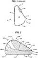
- Fig. 1shows a cross-sectional side view of an exemplary prior art mammary tissue expander 4.
- the expanderhas a posterior face 10 that lies substantially flat and is placed against a patient's chest wall, and an anterior face 5 that faces outward from the chest wall when implanted.
- the anterior face 5includes an upper pole region 15 (i.e., the upper portion of the shell when the implant recipient is standing), a lower pole region 20 (i.e., the lower portion of the shell when the implant recipient is standing), and an apex 25 (corresponding to the point at which the nipple would be in a natural breast) separating the upper pole region and the lower pole region.
- the outer shell 35 of the expander 5is typically made of a silicone material and includes an injection port or other valve or self-sealing zone 40 through which saline or another fluid is injected over time into the contained inner region 30. In this manner, the volume of the expander can be increased over time until the desired size pocket is achieved.
- the present inventionovercomes the problems described above and provides for expansion in the appropriate direction in an appropriate sized implant. More specifically, the implants described herein allow for minimized lateral and vertical expansion, while providing a more anatomically correct profile with less fullness in the upper pole region and more fullness and anterior expansion in the lower pole region. As shown in the illustrative embodiment in Fig. 2 , the implant of the present invention includes reinforcement at various locations along the shell to provide for minimal expansion at various desired locations and full expansion at other predetermined locations, to result in an expander that has desired and varied expansion characteristics around its surface area when in actual use within the body.
- the expander 100 of Figs. 2 and 3similarly includes a posterior face 110 and an anterior face 105 that includes an upper pole region 115, a lower pole region 120, and an apex 125.
- the posterior faceis substantially flat when the shell is inflated and is the portion of the shell that lies against the patient's chest wall.
- the posterior faceis defined by periphery 141.
- the expanderalso includes an injection zone 40.
- the injection zonemay be an injection dome of the well-known type as illustrated in Fig. 1 , may be a self-sealing area, or any other suitable device/area through which fluid can be injected and/or removed from the implant.
- the outer shell 135 of the expander 100further includes one or more reinforcement zones, wherein a reinforcing material limits the expandability of the outer shell material.
- the outer shellis made of silicone, and the reinforcing material is a mesh, such as a polyester mesh, although any suitable implantable mesh may be used.
- the reinforcing materialmay be a silicone sheet having an elasticity equal to or lower than the elasticity of the shell.
- the area of the shell having a reinforcing material coupled to itwill have an overall elasticity less than any unreinforced area regardless of the elasticity of the reinforcing material. In a preferred embodiment, however, the reinforcing material has elasticity that is substantially lower than the elasticity of the shell.
- any other suitable materialmay be used that adequately functions to restrict expansion of the shell by having an elasticity that is equal to or less than that of the shell material.
- exemplary other materialsinclude silicone based polymers, composite materials, polyurethane, polypropylene, and other biocompatible polymeric materials.
- the reinforcing materialmay be coupled to the shell by covering the mesh with an un-vulcanized silicone sheet and pressing it into the shell such that the un-vulcanized silicone sheet essentially acts as a glue.
- the strength of the formed connectioncan be improved by curing the silicone at an elevated temperature over a period of time (i.e., 315-350 degrees Fahrenheit for approximately 30 minutes).
- the embodiment of Fig. 2includes a first reinforcement zone 140 and a second reinforcement zone 150, both of which are illustrated with cross-hatching.
- the first reinforcement zone 140has a first end 148 and a second end 144, and includes at least a peripheral rim portion 146 that extends from the periphery 141 of the posterior face 110 upward into the anterior face 105 by a predetermined distance to an upper periphery 103.
- the predetermined distancemay be constant around the periphery, or may vary along the periphery as shown in Fig. 2 .
- the first reinforcement zonemay further extend so as to coincide with the entirety of the posterior face, or some portion thereof.
- the first reinforcement zone 140restricts lateral and axial expansion of the shell in the peripheral area immediately adjacent to the posterior face. In this manner, the surgeon need not choose an expander having a smaller posterior face than desired in order to account for undesired lateral expansion around the perimeter of the base of the implant.
- the embodiment of Fig. 2further includes a second reinforcement zone 150.
- a first end 152 of the second reinforcement zonepreferably substantially abuts or overlaps a first end 148 of the first reinforcement zone 140 so that the upper pole region 115 of the expander is entirely reinforced as between the first and second reinforcement zones. In this manner, upon being infused with fluid, the expander is unable to appreciably expand in the upper pole region.
- the second reinforcement zoneextends from the first end 152 and along at least a portion of the anterior face region 105 of the expander, essentially forming a reinforced "hinge" like structure centered around the upper pole region 115, and having hinge points 149 on both sides where the first and second reinforcement zones first meet and start to overlap or abut each other.
- the reinforcement materialcovers from about 25% to about 80% of the shell surface area, and more preferably from about 50% to about 75% of the shell surface area.
- the second reinforcement zoneextends substantially to the apex 125 of the shell.
- the reinforcing materialis designed so that the degree of elasticity of the material varies at different locations.
- a uniform reinforcing materialparticularly when the elasticity of the reinforcing material is much different than that of the shell, it may be the case that somewhat sharp transition zones appear between the reinforced regions of the shell and the unreinforced regions.
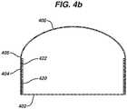
- An exemplary illustrationis shown in Fig. 4a , wherein the implant shell 400 is reinforced along the posterior face 402 and a peripheral region 404 similar to that described above. The difference in elasticity between the shell material and the reinforced zone may cause a sharp transition at the point 405 where the reinforced shell meets the unreinforced shell as demonstrated in Fig. 4a with an implant shell shown in three stages of inflation.
- the reinforcing materialhas varying elasticity properties at different locations, or simply have an elasticity gradient (gradually decreasing or increasing elasticity properties) in a given direction.
- elasticity of the reinforcing materialincreases in the direction towards the areas which are free of reinforcing material, or have less reinforcing material, so that the reinforcing material immediately adjacent the non-reinforced areas has the highest elasticity.
- Thiscan be accomplished by various means including, for example, providing apertures in the reinforcing material that vary in size and/or density along the length of the material. Exemplary embodiments are shown in Figs. 5a-5c , with Fig.
- Figs. 5a and 5cillustrating circular apertures of varying diameter 500a along the length of the material
- Figs. 5b and 5cillustrating varying slit-like aperture arrangements 500b, 500c along the length of the material.
- the thickness of the mesh or other materialmay vary along the length to achieve this result.
- both varying aperture size and/or aperture density (i.e., the number of apertures in a given area) along the length of the material and/or simultaneously varying thickness along the length of the materialare contemplated to provide the desired elasticity gradient.
- Figure 4billustrates the implant shell 400 having reinforcing zone 420 with a lower elasticity proximal to the posterior face 402 and a higher elasticity in the peripheral region 404, with elasticity increasing due to higher density of apertures 422 cut in the material 420. As can be seen from Figure 4b , elasticity is higher closest to the transition point 405 where the reinforced shell meets the unreinforced shell.
- the device illustrated in Figs. 2 and 3may further include an additional, separate reinforcing insert member 600 as illustrated in Figs. 6a and 6b .
- the insert memberis positioned entirely within the interior space 601 of the shell 635.
- the insert memberis sized and shaped to span the entire interior or the shell and is secured to the interior surface 607 of the shell around its entire periphery 602, preferably at a location substantially adjacent to the upper periphery 603 of the first reinforcement zone 644.
- the insert memberhelps minimize undesired effects at a transition zone of the type described above, and further assists in maintaining the desired shape of the implant during expansion.
- the insert membermay further include holes, apertures or the like 606, as illustrated in Fig.
- the insert membermay be in the form more of a "tether" or the like, such as a strip (or multiple strips) extending across the interior of the shell at any desired location, rather than having a configuration that substantially spans the entire interior.
- the insert membermay be formed of any suitable material having an elasticity that is suitable to increase the shell's resistance to outward expansion, such as DacronTM, polypropylene, DacronTM-silicone composite, etc.
- the insert membermay be secured to the inside of the shell using un-vulcanized silicone sheeting and heat, silicone-based adhesives, solvent-based bonding, diffusion bonding, ultrasonic welding, laser-spot welding, and other techniques known to a skilled artisan.
- Figs. 6c and 6dillustrate the implant of Fig. 3 having alternate insert member 600 therein.
- the insert member(shown in dotted lines in Fig. 6c ) is positioned in a substantially similar manner as illustrated in Figs. 6a and 6b , but has an alternate "half-moon" type shape, as shown clearly in Fig. 6d .
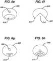
- the reinforcing insert member 600may have various other shapes and configurations, examples of which are shown in Figs. 6e-6h .
- the insert member 600has a cutout 610 generally shaped/positioned so that its first and second points 650, 651 correspond to or substantially align with the hinges 149 where the first and second reinforcement zones begin to overlap (see Fig. 2 ).
- the insert member 600has a large size aperture 618 which is generally shaped/positioned so as to correspond to the location of the hinges.
- the size and location of large size aperture 618are selected to locally increase elasticity of insert member 600, with area of the large size aperture 618 being from about 20% to about 40% of area of insert member 600, most preferably from about 20% to about 30% of area of insert member 600.
- Fig. 6gillustrates an insert member 600 with at least one optional aperture 606 and an array of slits 614 providing for increased elasticity of the insert member 600.
- the array 614is generally shaped/positioned so as to correspond to the location of the hinges.
- Fig. 6hillustrates an insert member 600 having a plurality of apertures 615 providing for increased elasticity of insert member 600, with apertures 615 generally shaped/positioned so as to correspond to location of hinge point as described previously.
Landscapes
- Health & Medical Sciences (AREA)
- Life Sciences & Earth Sciences (AREA)
- General Health & Medical Sciences (AREA)
- Public Health (AREA)
- Engineering & Computer Science (AREA)
- Biomedical Technology (AREA)
- Heart & Thoracic Surgery (AREA)
- Veterinary Medicine (AREA)
- Oral & Maxillofacial Surgery (AREA)
- Animal Behavior & Ethology (AREA)
- Vascular Medicine (AREA)
- Cardiology (AREA)
- Transplantation (AREA)
- Surgery (AREA)
- Dermatology (AREA)
- Nuclear Medicine, Radiotherapy & Molecular Imaging (AREA)
- Pathology (AREA)
- Medical Informatics (AREA)
- Molecular Biology (AREA)
- Prostheses (AREA)
Description
- The present invention relates generally to the field of expandable implants, and more particularly to expandable mammary implants.
- Tissue expanders are devices that are implanted beneath the skin and then gradually inflated to stretch the overlying tissue. Such expanders are used to create a pocket for receiving a permanent prosthesis and/or to generate increased skin surface area so that skin can be utilized for grafting or reconstruction.
- In the case of mammary implants, tissue expanders are used to create the mammary pocket that will ultimately receive the permanent mammary implant. These expanders are commonly formed of a silicone polymer shell. After implantation, saline or some other fluid is periodically injected into the expander over time, for example through an injection port, until the desired sized pocket is achieved.
- With known mammary tissue expanders, as the inflation process continues, resistive pressure from the tissue on the anterior side of the expander can cause the expander to expand in undesired directions (i.e., axially and laterally). In order to minimize the undesired expansion, most surgeons select a smaller expander than needed and overinflate the expander to 200-300 % of the rated volume of the expander. This allows the surgeon to utilize the smaller starting foot print of a smaller expander to accommodate for the undesired axial and lateral expansion. Overinflating a smaller expander is undesirable for various reasons. Although expanders are technically tested up to twice their nominal inflation volume, 200-300% inflation could reduce the safety margin of the device. Further, since the footprint is small, at 200-300% inflation the inflated shape is not anatomically correct, but rather is more round or ball-like, which could lead to rotation or flipping over of the implant within the tissue pocket.
- Thus, is would be desirable to provide an expandable mammary implant that better provides for the appropriate directional tissue expansion for any given size.
US 4,332,634A describes a method of preparing a resealable valve which has a resealable inner core and an outer reinforced cover. The method comprises first molding a hollow shell having a domed top and a bottom with a central opening, then turning the shell inside out and affixing a layer containing reinforcing fabric to the inside of the domed top, next turning the shell right side out and covering the bottom including the central opening with a layer containing reinforcing fabric to complete the cover, filling the thus formed cover with an uncured elastomer and finally curing the cover and its elastomer contents to form the resealable valve. The resealable valve can be used to add or remove fluid from an implanted medical device.- The present invention provides an expandable mammary tissue implant according to the appended claims.
Fig. 1 is a cross-sectional side view an exemplary prior art mammary tissue implant;Fig. 2 is a side view of an exemplary mammary tissue implant according to the present invention;Fig. 3 is a perspective view of the device ofFig. 2 ;Fig. 4a is an exemplary illustration of a possible transition zone between reinforced and non-reinforced portions of a shell;Fig. 4b illustrates the mammary implant ofFig. 3 further including a reinforcing material having varying elastic properties;Figs. 5a-5c illustrate exemplary embodiments of a reinforcing material having varying elastic properties along its length;Fig. 6a is a cross-sectional, perspective view illustrating a mammary tissue implant including an insert member;Fig. 6b illustrates an alternate configuration for a mammary implant having an insert member;Figs. 6c and 6d illustrate the mammary implant ofFig. 3 and further including an insert member; andFigs. 6e-6h illustrate various alternate embodiments of insert members.Fig. 1 shows a cross-sectional side view of an exemplary prior art mammary tissue expander 4. The expander has aposterior face 10 that lies substantially flat and is placed against a patient's chest wall, and ananterior face 5 that faces outward from the chest wall when implanted. Theanterior face 5 includes an upper pole region 15 (i.e., the upper portion of the shell when the implant recipient is standing), a lower pole region 20 (i.e., the lower portion of the shell when the implant recipient is standing), and an apex 25 (corresponding to the point at which the nipple would be in a natural breast) separating the upper pole region and the lower pole region. Theouter shell 35 of theexpander 5 is typically made of a silicone material and includes an injection port or other valve or self-sealing zone 40 through which saline or another fluid is injected over time into the containedinner region 30. In this manner, the volume of the expander can be increased over time until the desired size pocket is achieved.- With known expanders such as that shown in
Fig. 1 , although the overall shape of the expander when fully inflated as shown is somewhat anatomically correct, it has been found that when in use within the body, expansion does not occur in an anatomically correct or desired manner. This is because the expander ofFig. 1 is shown in air, and known expanders are designed and tested in air. Due to the minimal resistance of the surrounding air, an expander with an outer shell comprised of a substantially uniform material will expand to the final shape of that shell. In the body, however, the surrounding tissue and muscles counteract expansion, and a device with a substantially uniform outer shell will expand according to the path of least resistance, often determined by the varying resistance of the surrounding tissue. For mammary prostheses, this typically results in deformity of the outer shell to a more pancake like shape, with the anterior projection of the lower pole expansion being less than planned or desired, and lateral and axial expansion more than desired. As indicated previously, in an effort to increase the anterior projection of lower pole expansion, surgeons often pick undersized expanders having a smaller footprint (as against the chest wall), and over inflate them. - The present invention overcomes the problems described above and provides for expansion in the appropriate direction in an appropriate sized implant. More specifically, the implants described herein allow for minimized lateral and vertical expansion, while providing a more anatomically correct profile with less fullness in the upper pole region and more fullness and anterior expansion in the lower pole region. As shown in the illustrative embodiment in
Fig. 2 , the implant of the present invention includes reinforcement at various locations along the shell to provide for minimal expansion at various desired locations and full expansion at other predetermined locations, to result in an expander that has desired and varied expansion characteristics around its surface area when in actual use within the body. - The
expander 100 ofFigs. 2 and3 similarly includes aposterior face 110 and ananterior face 105 that includes anupper pole region 115, alower pole region 120, and anapex 125. As indicated previously, the posterior face is substantially flat when the shell is inflated and is the portion of the shell that lies against the patient's chest wall. The posterior face is defined byperiphery 141. The expander also includes aninjection zone 40. The injection zone may be an injection dome of the well-known type as illustrated inFig. 1 , may be a self-sealing area, or any other suitable device/area through which fluid can be injected and/or removed from the implant. - The
outer shell 135 of theexpander 100 further includes one or more reinforcement zones, wherein a reinforcing material limits the expandability of the outer shell material. According to one embodiment, the outer shell is made of silicone, and the reinforcing material is a mesh, such as a polyester mesh, although any suitable implantable mesh may be used. Alternatively, the reinforcing material may be a silicone sheet having an elasticity equal to or lower than the elasticity of the shell. The area of the shell having a reinforcing material coupled to it will have an overall elasticity less than any unreinforced area regardless of the elasticity of the reinforcing material. In a preferred embodiment, however, the reinforcing material has elasticity that is substantially lower than the elasticity of the shell. - Further, any other suitable material may be used that adequately functions to restrict expansion of the shell by having an elasticity that is equal to or less than that of the shell material. Exemplary other materials include silicone based polymers, composite materials, polyurethane, polypropylene, and other biocompatible polymeric materials. The reinforcing material may be coupled to the shell by covering the mesh with an un-vulcanized silicone sheet and pressing it into the shell such that the un-vulcanized silicone sheet essentially acts as a glue. The strength of the formed connection can be improved by curing the silicone at an elevated temperature over a period of time (i.e., 315-350 degrees Fahrenheit for approximately 30 minutes).
- The embodiment of
Fig. 2 includes afirst reinforcement zone 140 and asecond reinforcement zone 150, both of which are illustrated with cross-hatching. Thefirst reinforcement zone 140 has afirst end 148 and asecond end 144, and includes at least aperipheral rim portion 146 that extends from theperiphery 141 of theposterior face 110 upward into theanterior face 105 by a predetermined distance to anupper periphery 103. The predetermined distance may be constant around the periphery, or may vary along the periphery as shown inFig. 2 . The first reinforcement zone may further extend so as to coincide with the entirety of the posterior face, or some portion thereof. Thefirst reinforcement zone 140 restricts lateral and axial expansion of the shell in the peripheral area immediately adjacent to the posterior face. In this manner, the surgeon need not choose an expander having a smaller posterior face than desired in order to account for undesired lateral expansion around the perimeter of the base of the implant. - The embodiment of
Fig. 2 further includes asecond reinforcement zone 150. Afirst end 152 of the second reinforcement zone preferably substantially abuts or overlaps afirst end 148 of thefirst reinforcement zone 140 so that theupper pole region 115 of the expander is entirely reinforced as between the first and second reinforcement zones. In this manner, upon being infused with fluid, the expander is unable to appreciably expand in the upper pole region. The second reinforcement zone extends from thefirst end 152 and along at least a portion of theanterior face region 105 of the expander, essentially forming a reinforced "hinge" like structure centered around theupper pole region 115, and having hinge points 149 on both sides where the first and second reinforcement zones first meet and start to overlap or abut each other. In certain embodiments, the reinforcement material covers from about 25% to about 80% of the shell surface area, and more preferably from about 50% to about 75% of the shell surface area. - In this manner, expansion of the upper pole region beyond the intended shape is restricted, while more freely allowing desirable expansion of the
lower pole region 120. In one embodiment, the second reinforcement zone extends substantially to the apex 125 of the shell. - Although the embodiment above is described as having first and second pieces of reinforcing material, one skilled in the art will readily understand that the reinforcement zones can be established with a single piece as well.
- In a further aspect of the present invention, the reinforcing material is designed so that the degree of elasticity of the material varies at different locations. With a uniform reinforcing material, particularly when the elasticity of the reinforcing material is much different than that of the shell, it may be the case that somewhat sharp transition zones appear between the reinforced regions of the shell and the unreinforced regions. An exemplary illustration is shown in
Fig. 4a , wherein theimplant shell 400 is reinforced along theposterior face 402 and aperipheral region 404 similar to that described above. The difference in elasticity between the shell material and the reinforced zone may cause a sharp transition at thepoint 405 where the reinforced shell meets the unreinforced shell as demonstrated inFig. 4a with an implant shell shown in three stages of inflation. To minimize this possible effect, the reinforcing material has varying elasticity properties at different locations, or simply have an elasticity gradient (gradually decreasing or increasing elasticity properties) in a given direction. In a preferred embodiment, elasticity of the reinforcing material increases in the direction towards the areas which are free of reinforcing material, or have less reinforcing material, so that the reinforcing material immediately adjacent the non-reinforced areas has the highest elasticity. This can be accomplished by various means including, for example, providing apertures in the reinforcing material that vary in size and/or density along the length of the material. Exemplary embodiments are shown inFigs. 5a-5c , withFig. 5a illustrating circular apertures of varyingdiameter 500a along the length of the material, andFigs. 5b and 5c illustrating varying slit-like aperture arrangements Figure 4b illustrates theimplant shell 400 having reinforcingzone 420 with a lower elasticity proximal to theposterior face 402 and a higher elasticity in theperipheral region 404, with elasticity increasing due to higher density ofapertures 422 cut in thematerial 420. As can be seen fromFigure 4b , elasticity is higher closest to thetransition point 405 where the reinforced shell meets the unreinforced shell.- In yet another embodiment, the device illustrated in
Figs. 2 and3 may further include an additional, separate reinforcinginsert member 600 as illustrated inFigs. 6a and 6b . The insert member is positioned entirely within theinterior space 601 of theshell 635. In the illustrated embodiment, the insert member is sized and shaped to span the entire interior or the shell and is secured to theinterior surface 607 of the shell around itsentire periphery 602, preferably at a location substantially adjacent to theupper periphery 603 of thefirst reinforcement zone 644. The insert member helps minimize undesired effects at a transition zone of the type described above, and further assists in maintaining the desired shape of the implant during expansion. The insert member may further include holes, apertures or the like 606, as illustrated inFig. 6b , in order to allow movement of fluid within the shell as it is expanded. In alternate embodiments, the insert member may be in the form more of a "tether" or the like, such as a strip (or multiple strips) extending across the interior of the shell at any desired location, rather than having a configuration that substantially spans the entire interior. The insert member may be formed of any suitable material having an elasticity that is suitable to increase the shell's resistance to outward expansion, such as Dacron™, polypropylene, Dacron™-silicone composite, etc. The insert member may be secured to the inside of the shell using un-vulcanized silicone sheeting and heat, silicone-based adhesives, solvent-based bonding, diffusion bonding, ultrasonic welding, laser-spot welding, and other techniques known to a skilled artisan. Figs. 6c and 6d illustrate the implant ofFig. 3 havingalternate insert member 600 therein. In this embodiment, the insert member (shown in dotted lines inFig. 6c ) is positioned in a substantially similar manner as illustrated inFigs. 6a and 6b , but has an alternate "half-moon" type shape, as shown clearly inFig. 6d .- The reinforcing
insert member 600 may have various other shapes and configurations, examples of which are shown inFigs. 6e-6h . InFig. 6f , theinsert member 600 has acutout 610 generally shaped/positioned so that its first andsecond points hinges 149 where the first and second reinforcement zones begin to overlap (seeFig. 2 ). InFig. 6e , theinsert member 600 has alarge size aperture 618 which is generally shaped/positioned so as to correspond to the location of the hinges. The size and location oflarge size aperture 618 are selected to locally increase elasticity ofinsert member 600, with area of thelarge size aperture 618 being from about 20% to about 40% of area ofinsert member 600, most preferably from about 20% to about 30% of area ofinsert member 600.Fig. 6g illustrates aninsert member 600 with at least oneoptional aperture 606 and an array ofslits 614 providing for increased elasticity of theinsert member 600. Thearray 614 is generally shaped/positioned so as to correspond to the location of the hinges. - Finally,
Fig. 6h illustrates aninsert member 600 having a plurality ofapertures 615 providing for increased elasticity ofinsert member 600, withapertures 615 generally shaped/positioned so as to correspond to location of hinge point as described previously. - Although illustrative embodiments of the present invention have been described herein with reference to the accompanying drawings, it is to be understood that the invention is not limited to those precise embodiments and that various other changes and modifications may be effected herein by one skilled in the art without departing from the scope of the invention.
Claims (14)
- An expandable mammary implant (100) comprising:a shell (135) having an anterior face (105) and a posterior face (110), the anterior face having an upper pole portion (115) and a lower pole portion (120) meeting at an apex (125), and an injection zone (40) for receiving fluid therethrough to inflate the implant; anda reinforcement material coupled to the shell in a reinforcement zone (140, 150), wherein the reinforcement material is coupled to the shell so as to at least coincide with the upper pole portion and a peripheral rim portion (146) that extends from the posterior face upwardly into said anterior face by a predetermined distance,wherein the reinforcing material has varying elasticity properties at different locations.
- The implant according to claim 1, wherein the reinforcement zone (140, 150) further extends from the upper pole portion (115) along the anterior face by a second predetermined distance, said second predetermined distance being less than or equal to the distance from the upper pole portion to the apex of the shell.
- The implant according to claim 2, wherein the reinforcement zone (140, 150) further coincides with the entire posterior face (110) of the shell.
- The implant according to claim 3, wherein the predetermined distance that the reinforcement zone (140, 150) extends upwardly into the anterior face (105) of the shell varies around the periphery (141) of the posterior face (110) of the shell.
- The implant according to any preceding claim, wherein the reinforcing material is a mesh material.
- The implant according to claim 5, wherein the mesh material is a polypropylene mesh.
- The implant according to any preceding claim, wherein the shell (135) is comprised of silicone.
- The implant according to claim 1, wherein at least a portion of the reinforcing material has an elasticity gradient in a predetermined direction.
- The implant according to any preceding claim, further comprising at least one insert member (600) positioned entirely within and extending across an interior of said shell, and coupled to an interior surface of said shell.
- The implant according to claim 9, wherein the insert member (600) is sized and shaped so as to be coupled to the interior of the shell (135) around an entire perimeter of said insert member.
- The implant according to claim 10, wherein the perimeter of the insert member (600) is coupled to the interior of the shell (135) in a location substantially adjacent to an upper periphery of said reinforcement zone.
- The implant according to any of claims 9 to 11, wherein the insert member (600) has a plurality of apertures therethrough, and wherein the insert member has an elasticity gradient in a predetermined direction.
- The implant according to claim 9, wherein said at least one insert member (600) is a strip coupled to the interior surface of said shell (135) at first and second ends thereof.
- The expandable mammary tissue implant of claim 1, wherein the reinforcement zone (140. 150) covers the upper pole portion (115) such that upon inflation, expansion of the implant occurs disproportionately in the lower pole portion (120).
Applications Claiming Priority (3)
| Application Number | Priority Date | Filing Date | Title |
|---|---|---|---|
| US14/230,251US9700405B2 (en) | 2014-03-31 | 2014-03-31 | Directional tissue expander |
| PCT/US2015/019454WO2015153065A1 (en) | 2014-03-31 | 2015-03-09 | Directional tissue expander |
| EP15712224.3AEP3125824B1 (en) | 2014-03-31 | 2015-03-09 | Directional tissue expander |
Related Parent Applications (2)
| Application Number | Title | Priority Date | Filing Date |
|---|---|---|---|
| EP15712224.3ADivisionEP3125824B1 (en) | 2014-03-31 | 2015-03-09 | Directional tissue expander |
| EP15712224.3ADivision-IntoEP3125824B1 (en) | 2014-03-31 | 2015-03-09 | Directional tissue expander |
Publications (2)
| Publication Number | Publication Date |
|---|---|
| EP3443936A1 EP3443936A1 (en) | 2019-02-20 |
| EP3443936B1true EP3443936B1 (en) | 2021-07-14 |
Family
ID=52737406
Family Applications (2)
| Application Number | Title | Priority Date | Filing Date |
|---|---|---|---|
| EP18191483.9AActiveEP3443936B1 (en) | 2014-03-31 | 2015-03-09 | Directional tissue expander |
| EP15712224.3AActiveEP3125824B1 (en) | 2014-03-31 | 2015-03-09 | Directional tissue expander |
Family Applications After (1)
| Application Number | Title | Priority Date | Filing Date |
|---|---|---|---|
| EP15712224.3AActiveEP3125824B1 (en) | 2014-03-31 | 2015-03-09 | Directional tissue expander |
Country Status (8)
| Country | Link |
|---|---|
| US (2) | US9700405B2 (en) |
| EP (2) | EP3443936B1 (en) |
| KR (2) | KR102389437B1 (en) |
| AU (1) | AU2015241477B2 (en) |
| CA (1) | CA2943820C (en) |
| ES (2) | ES2701450T3 (en) |
| RU (1) | RU2698609C2 (en) |
| WO (1) | WO2015153065A1 (en) |
Families Citing this family (11)
| Publication number | Priority date | Publication date | Assignee | Title |
|---|---|---|---|---|
| US9463087B2 (en)* | 2014-03-31 | 2016-10-11 | Mentor Worldwide Llc | Directional tissue expander |
| CN120753591A (en) | 2016-02-09 | 2025-10-10 | 制定实验室公司 | Transponder and sensor for implantable medical device and method of use thereof |
| EP3531956A1 (en) | 2016-10-28 | 2019-09-04 | Establishment Labs S.A. | Tissue expanders, methods of manufacturing and molds thereof |
| ES2953544T3 (en) | 2018-02-09 | 2023-11-14 | Tepha Inc | Full contour breast implant |
| USD892329S1 (en) | 2018-07-03 | 2020-08-04 | Tepha, Inc. | Three dimensional mastopexy implant |
| EP3849458A1 (en) | 2018-09-13 | 2021-07-21 | Allergan, Inc. | Tissue expansion device |
| USD896383S1 (en) | 2018-09-13 | 2020-09-15 | Allergan, Inc. | Tissue expansion device |
| US11779455B2 (en) | 2018-10-02 | 2023-10-10 | Tepha, Inc. | Medical devices to limit movement of breast implants |
| BR112022010124A2 (en) | 2019-11-25 | 2022-09-06 | Tepha Inc | BREAST IMPLANT WRAPS TO LIMIT BREAST IMPLANT MOVEMENT AND RELATED METHODS |
| KR102686764B1 (en)* | 2021-02-19 | 2024-07-22 | 오스템임플란트 주식회사 | Prosthesis |
| US11357614B1 (en)* | 2021-06-11 | 2022-06-14 | Marcel Malek | Breast implant |
Family Cites Families (51)
| Publication number | Priority date | Publication date | Assignee | Title |
|---|---|---|---|---|
| DE2224963C3 (en)* | 1972-05-23 | 1975-03-27 | Otto Thaemert, Textil Und Kunststoff Gmbh & Co Kg, 3006 Grossburgwedel | Breast prosthesis |
| US4205401A (en)* | 1978-05-25 | 1980-06-03 | Dow Corning Corporation | Mammary prosthesis which resists capsular contracture |
| US4332634A (en)* | 1981-01-14 | 1982-06-01 | Medical Engineering Corporation | Method of preparing a resealable valve |
| US4605412A (en)* | 1983-01-20 | 1986-08-12 | Medical Engineering Corp. | Mammary prosthesis having adjustable projection |
| US4863470A (en) | 1985-03-19 | 1989-09-05 | Medical Engineering Corporation | Identification marker for a breast prosthesis |
| US4651717A (en) | 1985-04-04 | 1987-03-24 | Dow Corning Corporation | Multiple envelope tissue expander device |
| US4671255A (en) | 1985-10-16 | 1987-06-09 | Mcghan Medical Corporation | Tissue expander with self-contained injection reservoir and reinforcing insert |
| DE8701925U1 (en)* | 1987-02-09 | 1987-07-16 | Anita Spezialmiederfabrik Dr. Helbig GmbH & Co. KG, Kufstein | Breast prosthesis |
| US6228116B1 (en)* | 1987-12-22 | 2001-05-08 | Walter J. Ledergerber | Tissue expander |
| FR2630637B1 (en) | 1988-04-27 | 1997-09-12 | Muller Guy Henri | NEW ALVEOLAR PROSTHESIS |
| US5026394A (en) | 1989-01-10 | 1991-06-25 | Baker James L | Mammary implant |
| US4969899A (en)* | 1989-03-08 | 1990-11-13 | Cox-Uphoff International | Inflatable implant |
| US5496370A (en) | 1992-03-13 | 1996-03-05 | Robert S. Hamas | Gel-like prosthetic device |
| US5496367A (en) | 1993-01-13 | 1996-03-05 | Fisher; Jack | Breast implant with baffles |
| WO1996040003A1 (en) | 1995-06-07 | 1996-12-19 | Ledergerber Walter J | Tissue expander |
| US5776159A (en) | 1996-10-03 | 1998-07-07 | General Surgical Innovations, Inc. | Combination dissector and expander |
| US6146418A (en)* | 1997-02-28 | 2000-11-14 | Berman; Mark | Body implant and method of implanting |
| US6203570B1 (en)* | 1999-11-24 | 2001-03-20 | John L. Baeke | Breast implant with position lock |
| US6605116B2 (en) | 2001-04-03 | 2003-08-12 | Mentor Corporation | Reinforced radius mammary prostheses and soft tissue expanders |
| US20030144734A1 (en)* | 2002-01-28 | 2003-07-31 | Dreschnack Paul A. | Breast implant with locatable injection site |
| US6743254B2 (en) | 2002-02-01 | 2004-06-01 | Mentor Corporation | Tissue expander with protection against accidental puncture |
| AU2003902604A0 (en) | 2003-05-26 | 2003-06-12 | Connell, Anthony Francis | A differential tissue expander implant |
| BRPI0612094A2 (en) | 2005-06-28 | 2010-10-19 | Ami Glicksman | implantable human tissue dilator |
| US7615074B2 (en)* | 2005-08-25 | 2009-11-10 | Carvallo Edward | Method and apparatus for reconstructive surgery |
| US7625405B2 (en)* | 2006-02-08 | 2009-12-01 | Neosthetic, Llc | Breast implant and method of manufacture |
| CA2658891A1 (en) | 2006-07-24 | 2008-01-31 | Novalert, Inc. | Method and apparatus for minimally invasive implants |
| US8545557B2 (en) | 2007-01-03 | 2013-10-01 | Implite Ltd | Human implantable tissue expander |
| US8007532B2 (en) | 2007-06-05 | 2011-08-30 | Manders Ernest K | Dimensionally adjustable soft tissue expander |
| WO2009039373A1 (en)* | 2007-09-19 | 2009-03-26 | Ethicon, Inc. | Naturally contoured, preformed, three dimensional mesh device for breast implant support |
| US20090198331A1 (en) | 2008-02-01 | 2009-08-06 | Kesten Randy J | Implantable prosthesis with open cell flow regulation |
| US8506627B2 (en) | 2008-08-13 | 2013-08-13 | Allergan, Inc. | Soft filled prosthesis shell with discrete fixation surfaces |
| AU2009305623A1 (en) | 2008-10-17 | 2010-04-22 | Allergan, Inc. | Prosthetic implant shell |
| WO2010049926A2 (en) | 2008-10-28 | 2010-05-06 | Implite Ltd. | Reconstructive breast prostheses |
| BRPI0805495A2 (en)* | 2008-12-19 | 2010-09-08 | Miranda Jose Maria De | silicone implant with expandable and / or interactive compartments, whether or not lined with ricinus communis polyurethane foam and / or hydroxyapatite, with tabs or cords |
| US20110046729A1 (en) | 2009-08-18 | 2011-02-24 | Allergan, Inc. | Reinforced Prosthetic Implant With Flexible Shell |
| US20120226352A1 (en)* | 2009-09-02 | 2012-09-06 | Hilton Becker | Self supporting and forming breast implant and method for forming and supporting an implant in a human body |
| IL202160A0 (en) | 2009-11-16 | 2010-06-16 | Rolan Knowledge And Services L | Female breasts implants |
| AU2010330722B2 (en) | 2009-12-18 | 2015-08-20 | Airxpanders, Inc. | Tissue expanders and methods of use |
| US20130245758A1 (en)* | 2010-02-05 | 2013-09-19 | Allergan, Inc. | Inflatable prostheses and methods of making same |
| US20110301706A1 (en) | 2010-04-29 | 2011-12-08 | BioStruxs, LLC | Breast Reconstruction Device And Methods |
| EP2637604A1 (en)* | 2010-11-08 | 2013-09-18 | Allergan, Inc. | Tissue expander with self-healing anterior side |
| US8529624B2 (en)* | 2010-12-07 | 2013-09-10 | Miguel A. Linares | Breast and nipple implant constructions |
| US8871129B2 (en)* | 2012-05-31 | 2014-10-28 | Franck MOJARADI | Breast prosthesis |
| US9399122B2 (en)* | 2013-04-09 | 2016-07-26 | Reconstructive Technologies, Llc | Systems and methods for a tissue expander |
| RU2534868C1 (en)* | 2013-06-03 | 2014-12-10 | Федеральное государственное унитарное предприятие "Реутовский экспериментальный завод средств протезирования" Министерства здравоохранения и социального развития Российской Федерации | Method for making mammary implant, mammary implant and commercial application of mammary implant for breast tissue imitation |
| CN103393482B (en)* | 2013-08-14 | 2016-04-06 | 北京瑞健高科生物科技有限公司 | A kind of mammary prostheses supporting device based on tissue matrix material and preparation method thereof |
| EP2915505B1 (en)* | 2014-03-07 | 2018-01-10 | Novus Scientific AB | Support device used in medical breast reconstruction |
| US9463087B2 (en)* | 2014-03-31 | 2016-10-11 | Mentor Worldwide Llc | Directional tissue expander |
| FR3022451B1 (en)* | 2014-06-23 | 2016-07-01 | New-Team | EXTERNAL BREAST PROSTHESIS |
| EP3085337B1 (en)* | 2015-04-24 | 2022-09-14 | Sofradim Production | Prosthesis for supporting a breast structure |
| US10709545B2 (en)* | 2017-03-27 | 2020-07-14 | Allergan, Inc. | Implantable prostheses for tissue expansion |
- 2014
- 2014-03-31USUS14/230,251patent/US9700405B2/enactiveActive
- 2015
- 2015-03-09ESES15712224Tpatent/ES2701450T3/enactiveActive
- 2015-03-09WOPCT/US2015/019454patent/WO2015153065A1/enactiveApplication Filing
- 2015-03-09AUAU2015241477Apatent/AU2015241477B2/enactiveActive
- 2015-03-09CACA2943820Apatent/CA2943820C/enactiveActive
- 2015-03-09KRKR1020217009075Apatent/KR102389437B1/enactiveActive
- 2015-03-09KRKR1020167030520Apatent/KR102399640B1/enactiveActive
- 2015-03-09ESES18191483Tpatent/ES2884141T3/enactiveActive
- 2015-03-09RURU2016142380Apatent/RU2698609C2/enactive
- 2015-03-09EPEP18191483.9Apatent/EP3443936B1/enactiveActive
- 2015-03-09EPEP15712224.3Apatent/EP3125824B1/enactiveActive
- 2017
- 2017-06-27USUS15/634,931patent/US10617516B2/enactiveActive
Also Published As
| Publication number | Publication date |
|---|---|
| EP3443936A1 (en) | 2019-02-20 |
| RU2698609C2 (en) | 2019-08-28 |
| NZ760890A (en) | 2021-04-30 |
| KR102399640B1 (en) | 2022-05-19 |
| CA2943820A1 (en) | 2015-10-08 |
| AU2015241477B2 (en) | 2019-05-16 |
| WO2015153065A1 (en) | 2015-10-08 |
| RU2016142380A3 (en) | 2018-11-09 |
| AU2015241477A1 (en) | 2016-10-20 |
| KR102389437B1 (en) | 2022-04-25 |
| US9700405B2 (en) | 2017-07-11 |
| CA2943820C (en) | 2022-08-02 |
| KR20210037735A (en) | 2021-04-06 |
| ES2884141T3 (en) | 2021-12-10 |
| KR20160141800A (en) | 2016-12-09 |
| ES2701450T3 (en) | 2019-02-22 |
| RU2016142380A (en) | 2018-05-07 |
| NZ724421A (en) | 2021-04-30 |
| US20150272722A1 (en) | 2015-10-01 |
| US10617516B2 (en) | 2020-04-14 |
| US20170319328A1 (en) | 2017-11-09 |
| EP3125824B1 (en) | 2018-10-31 |
| EP3125824A1 (en) | 2017-02-08 |
Similar Documents
| Publication | Publication Date | Title |
|---|---|---|
| EP3443936B1 (en) | Directional tissue expander | |
| US9463087B2 (en) | Directional tissue expander | |
| AU2016229479B2 (en) | Tissue expander with pectoral attachment | |
| JP2014514126A (en) | Expandable prosthesis and method for making such a prosthesis | |
| KR20130004575A (en) | Inflatable prostheses and methods of making same | |
| NZ724421B2 (en) | Directional tissue expander | |
| NZ760890B2 (en) | Directional tissue expander |
Legal Events
| Date | Code | Title | Description |
|---|---|---|---|
| PUAI | Public reference made under article 153(3) epc to a published international application that has entered the european phase | Free format text:ORIGINAL CODE: 0009012 | |
| STAA | Information on the status of an ep patent application or granted ep patent | Free format text:STATUS: THE APPLICATION HAS BEEN PUBLISHED | |
| AC | Divisional application: reference to earlier application | Ref document number:3125824 Country of ref document:EP Kind code of ref document:P | |
| AK | Designated contracting states | Kind code of ref document:A1 Designated state(s):AL AT BE BG CH CY CZ DE DK EE ES FI FR GB GR HR HU IE IS IT LI LT LU LV MC MK MT NL NO PL PT RO RS SE SI SK SM TR | |
| STAA | Information on the status of an ep patent application or granted ep patent | Free format text:STATUS: REQUEST FOR EXAMINATION WAS MADE | |
| 17P | Request for examination filed | Effective date:20190809 | |
| RBV | Designated contracting states (corrected) | Designated state(s):AL AT BE BG CH CY CZ DE DK EE ES FI FR GB GR HR HU IE IS IT LI LT LU LV MC MK MT NL NO PL PT RO RS SE SI SK SM TR | |
| GRAP | Despatch of communication of intention to grant a patent | Free format text:ORIGINAL CODE: EPIDOSNIGR1 | |
| STAA | Information on the status of an ep patent application or granted ep patent | Free format text:STATUS: GRANT OF PATENT IS INTENDED | |
| INTG | Intention to grant announced | Effective date:20210319 | |
| GRAS | Grant fee paid | Free format text:ORIGINAL CODE: EPIDOSNIGR3 | |
| GRAA | (expected) grant | Free format text:ORIGINAL CODE: 0009210 | |
| STAA | Information on the status of an ep patent application or granted ep patent | Free format text:STATUS: THE PATENT HAS BEEN GRANTED | |
| AC | Divisional application: reference to earlier application | Ref document number:3125824 Country of ref document:EP Kind code of ref document:P | |
| AK | Designated contracting states | Kind code of ref document:B1 Designated state(s):AL AT BE BG CH CY CZ DE DK EE ES FI FR GB GR HR HU IE IS IT LI LT LU LV MC MK MT NL NO PL PT RO RS SE SI SK SM TR | |
| REG | Reference to a national code | Ref country code:GB Ref legal event code:FG4D | |
| REG | Reference to a national code | Ref country code:IE Ref legal event code:FG4D | |
| REG | Reference to a national code | Ref country code:DE Ref legal event code:R096 Ref document number:602015071401 Country of ref document:DE | |
| REG | Reference to a national code | Ref country code:AT Ref legal event code:REF Ref document number:1410062 Country of ref document:AT Kind code of ref document:T Effective date:20210815 | |
| REG | Reference to a national code | Ref country code:LT Ref legal event code:MG9D | |
| REG | Reference to a national code | Ref country code:NL Ref legal event code:MP Effective date:20210714 | |
| REG | Reference to a national code | Ref country code:ES Ref legal event code:FG2A Ref document number:2884141 Country of ref document:ES Kind code of ref document:T3 Effective date:20211210 | |
| REG | Reference to a national code | Ref country code:AT Ref legal event code:MK05 Ref document number:1410062 Country of ref document:AT Kind code of ref document:T Effective date:20210714 | |
| PG25 | Lapsed in a contracting state [announced via postgrant information from national office to epo] | Ref country code:RS Free format text:LAPSE BECAUSE OF FAILURE TO SUBMIT A TRANSLATION OF THE DESCRIPTION OR TO PAY THE FEE WITHIN THE PRESCRIBED TIME-LIMIT Effective date:20210714 Ref country code:SE Free format text:LAPSE BECAUSE OF FAILURE TO SUBMIT A TRANSLATION OF THE DESCRIPTION OR TO PAY THE FEE WITHIN THE PRESCRIBED TIME-LIMIT Effective date:20210714 Ref country code:HR Free format text:LAPSE BECAUSE OF FAILURE TO SUBMIT A TRANSLATION OF THE DESCRIPTION OR TO PAY THE FEE WITHIN THE PRESCRIBED TIME-LIMIT Effective date:20210714 Ref country code:FI Free format text:LAPSE BECAUSE OF FAILURE TO SUBMIT A TRANSLATION OF THE DESCRIPTION OR TO PAY THE FEE WITHIN THE PRESCRIBED TIME-LIMIT Effective date:20210714 Ref country code:NO Free format text:LAPSE BECAUSE OF FAILURE TO SUBMIT A TRANSLATION OF THE DESCRIPTION OR TO PAY THE FEE WITHIN THE PRESCRIBED TIME-LIMIT Effective date:20211014 Ref country code:PT Free format text:LAPSE BECAUSE OF FAILURE TO SUBMIT A TRANSLATION OF THE DESCRIPTION OR TO PAY THE FEE WITHIN THE PRESCRIBED TIME-LIMIT Effective date:20211115 Ref country code:NL Free format text:LAPSE BECAUSE OF FAILURE TO SUBMIT A TRANSLATION OF THE DESCRIPTION OR TO PAY THE FEE WITHIN THE PRESCRIBED TIME-LIMIT Effective date:20210714 Ref country code:LT Free format text:LAPSE BECAUSE OF FAILURE TO SUBMIT A TRANSLATION OF THE DESCRIPTION OR TO PAY THE FEE WITHIN THE PRESCRIBED TIME-LIMIT Effective date:20210714 Ref country code:AT Free format text:LAPSE BECAUSE OF FAILURE TO SUBMIT A TRANSLATION OF THE DESCRIPTION OR TO PAY THE FEE WITHIN THE PRESCRIBED TIME-LIMIT Effective date:20210714 Ref country code:BG Free format text:LAPSE BECAUSE OF FAILURE TO SUBMIT A TRANSLATION OF THE DESCRIPTION OR TO PAY THE FEE WITHIN THE PRESCRIBED TIME-LIMIT Effective date:20211014 | |
| PG25 | Lapsed in a contracting state [announced via postgrant information from national office to epo] | Ref country code:PL Free format text:LAPSE BECAUSE OF FAILURE TO SUBMIT A TRANSLATION OF THE DESCRIPTION OR TO PAY THE FEE WITHIN THE PRESCRIBED TIME-LIMIT Effective date:20210714 Ref country code:LV Free format text:LAPSE BECAUSE OF FAILURE TO SUBMIT A TRANSLATION OF THE DESCRIPTION OR TO PAY THE FEE WITHIN THE PRESCRIBED TIME-LIMIT Effective date:20210714 Ref country code:GR Free format text:LAPSE BECAUSE OF FAILURE TO SUBMIT A TRANSLATION OF THE DESCRIPTION OR TO PAY THE FEE WITHIN THE PRESCRIBED TIME-LIMIT Effective date:20211015 | |
| REG | Reference to a national code | Ref country code:DE Ref legal event code:R097 Ref document number:602015071401 Country of ref document:DE | |
| PG25 | Lapsed in a contracting state [announced via postgrant information from national office to epo] | Ref country code:DK Free format text:LAPSE BECAUSE OF FAILURE TO SUBMIT A TRANSLATION OF THE DESCRIPTION OR TO PAY THE FEE WITHIN THE PRESCRIBED TIME-LIMIT Effective date:20210714 | |
| PLBE | No opposition filed within time limit | Free format text:ORIGINAL CODE: 0009261 | |
| STAA | Information on the status of an ep patent application or granted ep patent | Free format text:STATUS: NO OPPOSITION FILED WITHIN TIME LIMIT | |
| PG25 | Lapsed in a contracting state [announced via postgrant information from national office to epo] | Ref country code:SM Free format text:LAPSE BECAUSE OF FAILURE TO SUBMIT A TRANSLATION OF THE DESCRIPTION OR TO PAY THE FEE WITHIN THE PRESCRIBED TIME-LIMIT Effective date:20210714 Ref country code:SK Free format text:LAPSE BECAUSE OF FAILURE TO SUBMIT A TRANSLATION OF THE DESCRIPTION OR TO PAY THE FEE WITHIN THE PRESCRIBED TIME-LIMIT Effective date:20210714 Ref country code:RO Free format text:LAPSE BECAUSE OF FAILURE TO SUBMIT A TRANSLATION OF THE DESCRIPTION OR TO PAY THE FEE WITHIN THE PRESCRIBED TIME-LIMIT Effective date:20210714 Ref country code:EE Free format text:LAPSE BECAUSE OF FAILURE TO SUBMIT A TRANSLATION OF THE DESCRIPTION OR TO PAY THE FEE WITHIN THE PRESCRIBED TIME-LIMIT Effective date:20210714 Ref country code:CZ Free format text:LAPSE BECAUSE OF FAILURE TO SUBMIT A TRANSLATION OF THE DESCRIPTION OR TO PAY THE FEE WITHIN THE PRESCRIBED TIME-LIMIT Effective date:20210714 Ref country code:AL Free format text:LAPSE BECAUSE OF FAILURE TO SUBMIT A TRANSLATION OF THE DESCRIPTION OR TO PAY THE FEE WITHIN THE PRESCRIBED TIME-LIMIT Effective date:20210714 | |
| 26N | No opposition filed | Effective date:20220419 | |
| PG25 | Lapsed in a contracting state [announced via postgrant information from national office to epo] | Ref country code:MC Free format text:LAPSE BECAUSE OF FAILURE TO SUBMIT A TRANSLATION OF THE DESCRIPTION OR TO PAY THE FEE WITHIN THE PRESCRIBED TIME-LIMIT Effective date:20210714 | |
| REG | Reference to a national code | Ref country code:CH Ref legal event code:PL | |
| REG | Reference to a national code | Ref country code:BE Ref legal event code:MM Effective date:20220331 | |
| PG25 | Lapsed in a contracting state [announced via postgrant information from national office to epo] | Ref country code:LU Free format text:LAPSE BECAUSE OF NON-PAYMENT OF DUE FEES Effective date:20220309 Ref country code:LI Free format text:LAPSE BECAUSE OF NON-PAYMENT OF DUE FEES Effective date:20220331 Ref country code:IE Free format text:LAPSE BECAUSE OF NON-PAYMENT OF DUE FEES Effective date:20220309 Ref country code:FR Free format text:LAPSE BECAUSE OF NON-PAYMENT OF DUE FEES Effective date:20220331 Ref country code:CH Free format text:LAPSE BECAUSE OF NON-PAYMENT OF DUE FEES Effective date:20220331 | |
| PG25 | Lapsed in a contracting state [announced via postgrant information from national office to epo] | Ref country code:BE Free format text:LAPSE BECAUSE OF NON-PAYMENT OF DUE FEES Effective date:20220331 | |
| PG25 | Lapsed in a contracting state [announced via postgrant information from national office to epo] | Ref country code:HU Free format text:LAPSE BECAUSE OF FAILURE TO SUBMIT A TRANSLATION OF THE DESCRIPTION OR TO PAY THE FEE WITHIN THE PRESCRIBED TIME-LIMIT; INVALID AB INITIO Effective date:20150309 | |
| PG25 | Lapsed in a contracting state [announced via postgrant information from national office to epo] | Ref country code:MK Free format text:LAPSE BECAUSE OF FAILURE TO SUBMIT A TRANSLATION OF THE DESCRIPTION OR TO PAY THE FEE WITHIN THE PRESCRIBED TIME-LIMIT Effective date:20210714 Ref country code:CY Free format text:LAPSE BECAUSE OF FAILURE TO SUBMIT A TRANSLATION OF THE DESCRIPTION OR TO PAY THE FEE WITHIN THE PRESCRIBED TIME-LIMIT Effective date:20210714 | |
| PG25 | Lapsed in a contracting state [announced via postgrant information from national office to epo] | Ref country code:MT Free format text:LAPSE BECAUSE OF FAILURE TO SUBMIT A TRANSLATION OF THE DESCRIPTION OR TO PAY THE FEE WITHIN THE PRESCRIBED TIME-LIMIT Effective date:20210714 | |
| PGFP | Annual fee paid to national office [announced via postgrant information from national office to epo] | Ref country code:DE Payment date:20250128 Year of fee payment:11 | |
| PGFP | Annual fee paid to national office [announced via postgrant information from national office to epo] | Ref country code:GB Payment date:20250130 Year of fee payment:11 Ref country code:IT Payment date:20250211 Year of fee payment:11 | |
| PGFP | Annual fee paid to national office [announced via postgrant information from national office to epo] | Ref country code:ES Payment date:20250411 Year of fee payment:11 |