EP3441023B1 - Laparoscopic forceps assembly - Google Patents
Laparoscopic forceps assemblyDownload PDFInfo
- Publication number
- EP3441023B1 EP3441023B1EP18192612.2AEP18192612AEP3441023B1EP 3441023 B1EP3441023 B1EP 3441023B1EP 18192612 AEP18192612 AEP 18192612AEP 3441023 B1EP3441023 B1EP 3441023B1
- Authority
- EP
- European Patent Office
- Prior art keywords
- tubular member
- jaws
- blade
- pair
- shaft
- Prior art date
- Legal status (The legal status is an assumption and is not a legal conclusion. Google has not performed a legal analysis and makes no representation as to the accuracy of the status listed.)
- Active
Links
Images


Classifications
- A—HUMAN NECESSITIES
- A61—MEDICAL OR VETERINARY SCIENCE; HYGIENE
- A61B—DIAGNOSIS; SURGERY; IDENTIFICATION
- A61B18/00—Surgical instruments, devices or methods for transferring non-mechanical forms of energy to or from the body
- A61B18/04—Surgical instruments, devices or methods for transferring non-mechanical forms of energy to or from the body by heating
- A61B18/12—Surgical instruments, devices or methods for transferring non-mechanical forms of energy to or from the body by heating by passing a current through the tissue to be heated, e.g. high-frequency current
- A61B18/14—Probes or electrodes therefor
- A61B18/1442—Probes having pivoting end effectors, e.g. forceps
- A61B18/1445—Probes having pivoting end effectors, e.g. forceps at the distal end of a shaft, e.g. forceps or scissors at the end of a rigid rod
- A61B18/1447—Probes having pivoting end effectors, e.g. forceps at the distal end of a shaft, e.g. forceps or scissors at the end of a rigid rod wherein sliding surfaces cause opening/closing of the end effectors
- A—HUMAN NECESSITIES
- A61—MEDICAL OR VETERINARY SCIENCE; HYGIENE
- A61B—DIAGNOSIS; SURGERY; IDENTIFICATION
- A61B17/00—Surgical instruments, devices or methods
- A61B17/28—Surgical forceps
- A61B17/29—Forceps for use in minimally invasive surgery
- A—HUMAN NECESSITIES
- A61—MEDICAL OR VETERINARY SCIENCE; HYGIENE
- A61B—DIAGNOSIS; SURGERY; IDENTIFICATION
- A61B17/00—Surgical instruments, devices or methods
- A61B17/28—Surgical forceps
- A61B17/29—Forceps for use in minimally invasive surgery
- A61B17/295—Forceps for use in minimally invasive surgery combined with cutting implements
- A—HUMAN NECESSITIES
- A61—MEDICAL OR VETERINARY SCIENCE; HYGIENE
- A61B—DIAGNOSIS; SURGERY; IDENTIFICATION
- A61B18/00—Surgical instruments, devices or methods for transferring non-mechanical forms of energy to or from the body
- A61B18/04—Surgical instruments, devices or methods for transferring non-mechanical forms of energy to or from the body by heating
- A61B18/12—Surgical instruments, devices or methods for transferring non-mechanical forms of energy to or from the body by heating by passing a current through the tissue to be heated, e.g. high-frequency current
- A61B18/14—Probes or electrodes therefor
- A61B18/1442—Probes having pivoting end effectors, e.g. forceps
- A61B18/1445—Probes having pivoting end effectors, e.g. forceps at the distal end of a shaft, e.g. forceps or scissors at the end of a rigid rod
- A—HUMAN NECESSITIES
- A61—MEDICAL OR VETERINARY SCIENCE; HYGIENE
- A61B—DIAGNOSIS; SURGERY; IDENTIFICATION
- A61B17/00—Surgical instruments, devices or methods
- A61B17/28—Surgical forceps
- A61B17/29—Forceps for use in minimally invasive surgery
- A61B2017/2901—Details of shaft
- A61B2017/2902—Details of shaft characterized by features of the actuating rod
- A—HUMAN NECESSITIES
- A61—MEDICAL OR VETERINARY SCIENCE; HYGIENE
- A61B—DIAGNOSIS; SURGERY; IDENTIFICATION
- A61B17/00—Surgical instruments, devices or methods
- A61B17/28—Surgical forceps
- A61B17/29—Forceps for use in minimally invasive surgery
- A61B2017/2926—Details of heads or jaws
- A—HUMAN NECESSITIES
- A61—MEDICAL OR VETERINARY SCIENCE; HYGIENE
- A61B—DIAGNOSIS; SURGERY; IDENTIFICATION
- A61B17/00—Surgical instruments, devices or methods
- A61B17/28—Surgical forceps
- A61B17/29—Forceps for use in minimally invasive surgery
- A61B2017/2926—Details of heads or jaws
- A61B2017/2932—Transmission of forces to jaw members
- A61B2017/2933—Transmission of forces to jaw members camming or guiding means
- A61B2017/2934—Transmission of forces to jaw members camming or guiding means arcuate shaped guiding means
- A—HUMAN NECESSITIES
- A61—MEDICAL OR VETERINARY SCIENCE; HYGIENE
- A61B—DIAGNOSIS; SURGERY; IDENTIFICATION
- A61B17/00—Surgical instruments, devices or methods
- A61B17/28—Surgical forceps
- A61B17/29—Forceps for use in minimally invasive surgery
- A61B2017/2926—Details of heads or jaws
- A61B2017/2932—Transmission of forces to jaw members
- A61B2017/2933—Transmission of forces to jaw members camming or guiding means
- A61B2017/2937—Transmission of forces to jaw members camming or guiding means with flexible part
- A—HUMAN NECESSITIES
- A61—MEDICAL OR VETERINARY SCIENCE; HYGIENE
- A61B—DIAGNOSIS; SURGERY; IDENTIFICATION
- A61B17/00—Surgical instruments, devices or methods
- A61B17/28—Surgical forceps
- A61B17/29—Forceps for use in minimally invasive surgery
- A61B2017/2926—Details of heads or jaws
- A61B2017/2932—Transmission of forces to jaw members
- A61B2017/2944—Translation of jaw members
- A—HUMAN NECESSITIES
- A61—MEDICAL OR VETERINARY SCIENCE; HYGIENE
- A61B—DIAGNOSIS; SURGERY; IDENTIFICATION
- A61B18/00—Surgical instruments, devices or methods for transferring non-mechanical forms of energy to or from the body
- A61B18/04—Surgical instruments, devices or methods for transferring non-mechanical forms of energy to or from the body by heating
- A61B18/12—Surgical instruments, devices or methods for transferring non-mechanical forms of energy to or from the body by heating by passing a current through the tissue to be heated, e.g. high-frequency current
- A61B18/14—Probes or electrodes therefor
- A61B18/1442—Probes having pivoting end effectors, e.g. forceps
- A61B2018/1452—Probes having pivoting end effectors, e.g. forceps including means for cutting
- A61B2018/1455—Probes having pivoting end effectors, e.g. forceps including means for cutting having a moving blade for cutting tissue grasped by the jaws
- A—HUMAN NECESSITIES
- A61—MEDICAL OR VETERINARY SCIENCE; HYGIENE
- A61B—DIAGNOSIS; SURGERY; IDENTIFICATION
- A61B18/00—Surgical instruments, devices or methods for transferring non-mechanical forms of energy to or from the body
- A61B18/04—Surgical instruments, devices or methods for transferring non-mechanical forms of energy to or from the body by heating
- A61B18/12—Surgical instruments, devices or methods for transferring non-mechanical forms of energy to or from the body by heating by passing a current through the tissue to be heated, e.g. high-frequency current
- A61B18/14—Probes or electrodes therefor
- A61B18/1442—Probes having pivoting end effectors, e.g. forceps
- A61B2018/1452—Probes having pivoting end effectors, e.g. forceps including means for cutting
- A61B2018/1457—Probes having pivoting end effectors, e.g. forceps including means for cutting having opposing blades cutting tissue grasped by the jaws, i.e. combined scissors and pliers
Definitions
- the disclosurerelates to forceps with a spacing member between two opposing jaws, a tubing member with a non-circular profile, or both.
- forcepsmay be utilized for laparoscopic surgery.
- the forcepsmay be used to control delicate movements inside a patient. These forceps may be used to grip an anatomical feature.
- the forcepsmay include a gripping assembly or a cutting assembly.
- the forcepsmay include electrical energy for use in the gripping assembly.
- the forcepshave a pair of opposed resilient jaws that are closed against each other by pulling the jaws into a distal end of a shaft that captures a portion of the jaws that is wider than the distal end opening of the shaft so that the jaws are moved together. Similarly the shaft may be pushed over the jaws so that the jaws are moved together to create a gripping force.
- Some laparoscopic forcepsinclude jaws that have two legs that are connected at a distal end forming a gap between the two legs so that a blade can travel down the gap in center of the two opposing jaws.
- the jawsmay be moved into contact with the blade creating a drag force which may prevent the blade from moving and/or may cause misalignment of the blade.
- the camming force on the opposing jawsmay not be equal and the uneven application of forces on the opposing jaws may cause the distal ends of the jaws to be misaligned during gripping.
- the laparoscopic forceps after the jaws are released and the jaws are no longer constrained by the shafttypically move apart.
- This opening forcemay be used to push apart tissue by extending the closed jaws proximate to tissue and then allowing the jaws to open so that tissue is moved.
- some of the laparoscopic forceps when released from a closed positiondo not have a sufficient amount of force to move tissue for dissection.
- Other active dissection toolsallow the user to open and close the jaws through mechanical linkages. These mechanical linkages generally allow the user some control over the amount of force applied to the tissue.
- the mechanical linkagesinclude multiple delicate parts that are difficult to assemble, are expensive, and results in a complex device to move tissue.
- the forcepswould be attractive for the forceps to include a device that controls the movement between the two opposing jaws. What is needed is a device that assists in biasing the jaws and maintains alignment of the blade. What is needed is a device that opens the jaws. It would be attractive to have a device that spreads the jaws with sufficient force so that the jaws can be used for dissection. What is needed is a device that spreads the jaws and does not interfere with a reciprocating blade
- WO 95/07662 A1discloses an endoscopic forceps having two jaws separated from each other by tabs on the distal end of the tubular member, the tabs interacting with arcuate surfaces on the jaws to open and close the jaws.
- a laparoscopic forcepscomprising a handpiece including a distal end portion; a tubular member protruding from the distal end portion of the handpiece, the tubular member having a distal end with a distal opening, a pair of jaws having legs that are disposed within the tubular member and partially protruding from the distal opening in the distal end of the tubular member, the pair of jaws and the tubular member being movable relative to each other in a direction parallel to a longitudinal axis of the tubular member; wherein each of the pair of jaws has an arcuate section; an operable mechanism for creating relative motion between the pair of jaws and the tubular member along a direction parallel to the longitudinal axis of the tubular member, and one or more spacing members extending across the distal opening of the tubular member and between the pair of jaws; wherein the pair of jaws are closable by the relative movement of the tubular member and the pair of jaws towards each other
- a laparoscopic forcepscomprising: a handpiece including a distal end portion; a tubular member protruding from the distal end portion of the handpiece, the tubular member having a distal end, a pair of jaws having legs that are disposed within the tubular member and partially protruding from the distal end of the tubular member, the pair of jaws and the tubular member being movable relative to each other in a direction parallel to a longitudinal axis of the tubular member; wherein each of the pair of jaws has an arcuate section, and the pair of jaws are closable by advancing the tubular member over the arcuate section of the jaws; and an operable mechanism for creating relative motion between the pair of jaws and the tubular member along a direction parallel to the axis of the tubular member, wherein at least the distal end of the tubular member has a profile shape that is non-circular.
- a laparoscopic forcepscomprising: (a) a handpiece; (b) a jaw bias mechanism; (c) a tubular member including: (i) an outer tube, and (ii) an inner tube, wherein the outer tube and inner tube are configured for relative axial motion when acted upon by the jaw bias mechanism; and (d) two or more jaws that extend out of the tubular member and the two or more jaws pivot on a common axis that is anchored to the inner tube; wherein the outer tube, during actuation of the jaw bias mechanism, overruns the two or more jaws so that the two or more jaws are moved towards bias.
- a laparoscopic forcepscomprising: (1) a handpiece; (2) a jaw bias mechanism; (3) a tubular member including: (i) an outer tube, and (ii) an inner tube, wherein the outer tube and inner tube are movable relative to each other when acted upon by the jaw bias mechanism; (4) jaws extending from the tubular member and at least partially through the tubular member; and (5) a biasing element that biases the inner tube and outer tube relative to each other so that the biasing element biases the jaws open; wherein the jaws pivot on one or more axes that are anchored to the inner tube; and wherein the outer tube overruns the jaws so that the jaws are moved towards each other.
- the laparoscopic forcepsinclude a camming shaft that is located in the distal end of the tubular member; the one or more spacing members are a pair of opposing pins that include a blade recess therebetween, one continuous spacing member that extends across the distal opening of the tubular member, or both; the one or more spacing members include a generally mushroom shape and/or are crimped material of the tubular member, the camming shaft, or both; the one or more spacing members are one or more bars that extend out of the distal opening of the tubular member along the longitudinal axis of the tubular member; the one or more bars each include a bulbous portion at an end that increases a size of each of the one or more bars so that when the bulbous portion contacts the pair of opposing jaws, the legs of the jaws, or both the jaws are moved apart; the laparoscopic forceps include a blade and the blade has a pin recess that extends along the longitudinal axis of the tubular member, and the one or more spacing members
- the teachings hereinprovide forceps to include a device that controls the movement between the two opposing jaws.
- the present teachingsprovide a device that assists in biasing the jaws and maintains alignment of the blade.
- the present teachingsprovide a device that opens the jaws.
- the present teachingsprovide a device that spreads the jaws with sufficient force so that the jaws can be used for dissection.
- the present teachingsprovide a device that spreads the jaws and does not interfere with a reciprocating blade.
- the present teachingsclaim priority to U.S. Provisional No. 61/889,060, filed on October 10, 2013 .
- the present teachingsprovide a forceps device.
- the forcepsmay function to grip an object.
- the forcepsmay be used during surgery to grip a feature of interest including: a part of a body, an anatomical feature, tissue, veins, arteries, or a combination thereof.
- the forcepsmay function to be used in surgery, for example laparoscopic surgery.
- the forcepsmay be used with or without power. Current may be passed through the forceps so that the forceps are used for electrosurgery.
- a therapy currentmay be passed from one jaw to a second jaw when tissue is located within the jaw and the therapy current may coagulate blood, cauterize, cut, or a combination thereof.
- a therapy currentmay be passed from one or more of the jaws to a remote electrode (e.g., a return pad).
- the forcepsmay generally include one or more working assemblies and sufficient controls to work the one or more assemblies.
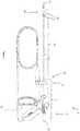
- the forcepsmay be comprised of parts needed to perform the recited functions and may include generally, a stylet (e.g., a tubular member, a hollow tube, or an assembly of tubes), a hand piece, one or more operable mechanisms used to actuate the stylet, or a combination thereof.
- the hand piecemay be an assembly of parts or housing structures capable of forming a hand piece structure with a cavity.
- the hand piecemay function to form an enclosing structure for the forceps, a gripping portion for the user, a main portion for manipulating the forceps, or a combination thereof.
- the hand piecemay be any device that houses the working assemblies and parts of the forceps.
- the hand piecemay be comprised of one or more housing structures. Preferably, the hand piece is two or more housing structures.
- the hand piecemay be any structure that is gripped by a user.
- the hand piecemay be any structure that combines one or more of the components discussed herein so that forceps are formed.
- the hand piecemay assist in performing laparoscopic surgery.
- the hand piecemay be ergonomically shaped.
- the ergonomic shape of the hand piecemay be any shape so that the forceps may be used ambidextrously.
- the ergonomic shape of the hand piecemay be any shape such that all the controls can be accessed by a single hand gripping the hand piece.
- the hand piecemay be comprised of housing structures.
- the housing structuresmay be one or more devices that form the hand piece.
- the housing structuresmay be any devices that may affix certain pieces into position.
- the housing structuresmay form a cavity to house working assemblies of the forceps.
- the housing structuresmay be one or more housing structures and preferably two or more housing structures.
- the housing structuresmay be any device that includes a recess for receiving one or more components of the forceps.
- the housing structuresmay house one or more operable mechanisms.
- the one or more operable mechanismsmay be one or more levers.
- the one or more operable mechanismsmay be any device that may be manipulated or moved by applying pressure to a portion of the one or more operable mechanisms with a hand, finger, foot, or a combination thereof.
- the one or more operable mechanismsmay be any device that may bias other moveable components, for example the tubular member, a cutting assembly, a blade assembly, a functional assembly, or a combination thereof.
- the one or more operable mechanismsmay be biased ambidextrously.
- the one or more operable mechanismsmay be a single operable mechanism that may be linked to two different functions and may be biased to generate each function individually or simultaneously.
- the operable mechanismmay include a double hinged pin and upon movement of the first hinge the jaws may be actuated and upon movement of the second pin the blade may be advanced.
- the one or more operable mechanismsmay be two operable mechanisms and each operable mechanism may be biased to perform a different function.
- the two operable mechanismsmay be a clamp operable mechanism and a cut trigger operable mechanism.
- the combination of two operable mechanismsmay include a forked two-sided cam finger, a yoke, or a combination thereof for actuating the one or more jaws, the one or more stylets, or a combination thereof.
- the one or more operable mechanismsmay include one or more cam fingers.
- each of the one or more operable mechanismsinclude a single cam finger.
- the one or more cam fingersmay translate movement from a user to the stylet, the blade, the jaws, or a combination thereof.
- the one or more cam fingersmay act upon a portion of the tubular member, the blade assembly, the jaw assembly, or a combination thereof that is located within the hand piece.
- the one or more cam fingers, the tubular member, the blade assembly, the jaw assembly, or a combination thereofmay be moved back to a starting position, moved to a predetermined position, or both once the one or more operable mechanisms are released.
- the movement back to a starting position, to a predetermined position, or bothmay be performed by a return mechanism that is in communication with the cam fingers, the operable mechanism, or both.
- the return mechanismmay assist in actuating one or more assemblies.
- the return mechanismmay return the one or more assemblies to a neutral position and/or a resting position after actuation.
- the return mechanismmay be any device that biases the tubular member and/or stylet to a resting position so that when the tubular member and/or stylet is actuated and released from actuation the tubular member and/or stylet returns back to a resting position.
- the return mechanismmay be and/or include a biasing member (e.g., a spring structure, an elastic member, a compressible member, a stretchable member, any structure that can be compressed and released, or a combination thereof).
- the return mechanismmay be a return spring.
- the return mechanismmay be connected to a proximal end of a stylet, a tubular member, or both.
- a proximal end of the tubular membermay be disposed in the cavity of the hand piece and one or more functional assemblies (e.g., a gripping assembly, a cutting assembly, or both) may be located at a distal end of the stylet, tubular member, or both.
- the gripping assemblymay function to create a gripping force, grip a feature of interest, or both.
- the gripping assemblymay be one or more devices or parts that provide a gripping force, grips one or more objects, or both.
- the gripping assemblymay be any combination of parts that may be used during surgery to grip one or more features of interest (e.g., tissue, veins, arteries, an anatomical feature, or a combination thereof).
- the gripping assemblymay be actuated by one or more operable mechanisms.
- the gripping assemblymay be used in surgery, for example laparoscopic surgery.
- the gripping assemblymay create a sufficient gripping force so that one or more features of interest of a patient's body may be manipulated by the gripping assembly, secured by the gripping assembly, or a combination thereof.
- the gripping assemblymay be composed of parts that may extend through the tubular member.
- the gripping assemblymay be an assembly of parts rotatable about an axis (e.g., a rotational axis of the gripping assembly, the longitudinal axis of the tubular member, a longitudinal axis of the gripping assembly, or a combination thereof).
- the gripping assemblymay grip and release while being simultaneously rotated.
- the gripping assemblymay be actuated by the actuation mechanism in communication with the gripping assembly.
- the gripping assemblymay be actuated by retracting the two opposing jaws into the stylet (e.g., one or more tubular members) forcing the two opposing jaws closed.
- the gripping assemblymay be actuated by extending the one or more tubular members away from the hand piece so that the one or more tubular members bias the two opposing jaws towards one another into a closed position, creating a gripping force, or both.
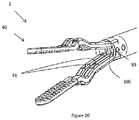
- the gripping assemblymay generally have two or more opposing jaws, and one or more jaw shafts or legs, or a combination of both.
- the gripping assemblymay have two jaw shafts or legs that each include an arcuate section and an opposing jaw attached to each of the jaw shafts or legs.
- the two or more opposing jawsmay function to create a gripping force.
- the two or more opposing jawsmay move towards each other to create a gripping force, to grip a feature of interest, or both.
- the two or more opposing jawsmay be any devices that may be used to grip items of interest in surgery, for example laparoscopic surgery.
- the two or more opposing jawsmay function to be used to grip or clamp an item of interest for cutting.
- the two or more opposing jawsmay be any shape and size so that the jaws perform a gripping function, create a gripping force, or both.
- the two or more opposing jawsmay be one jaw structure with another mirror image opposing jaw structure (i.e., identical) that when forced together may create a gripping function.
- the two opposing jawsmay be any two or more structures that may be movable relative to each other for perform a gripping function.
- the two opposing jawsmay be any structures that may allow one jaw to be static and one jaw to be movable or any combination thereof.
- the two opposing jawsmay include a gap (e.g., a blade track) to allow for a cutting instrument to be inserted while retaining functionality of the two or more opposing jaws.
- the gapmay be any shape and size so that a blade, functional element, a surgical instrument, or a combination thereof may be extended into the gap in the jaws, into the gap between the jaws, or both.
- the blade, a surgical instrument, functional element, or a combination thereofmay be extended into the gap formed in (or between) the two opposing jaws while the two opposing jaws are closed, open, or in a position therebetween.
- the gapmay be formed in the opposing jaws, the jaws may be made of a wire material that may be formed to include the gap, material may be removed to form the gap, or a combination thereof.
- the gap(e.g., blade track) may extend along the longitudinal axis of the tubular member, blade, or both so that the blade axially extends into the gap during use.
- the material the jaws are made ofmay be formed to include a gap.
- the two opposing jawsmay be made of any material so that the two opposing jaws may be used to create a gripping force.
- the two opposing jawsmay be made of a flexible material, resilient material, rigid stainless steel, a plastically deformable material, an elastically deformable material, or a combination thereof.
- the two opposing jawsmay be made of a material that conducts electricity.
- the jawsmay include a protective cover.
- the protective covermay function to prevent current leakage, prevent application of power to an undesired location, insulate the wires, create a contact location at a predetermined location, or a combination thereof.
- the protective covermay protect an outside of the jaws.
- the protective covermay prevent stray current.
- the protective covermay assist in directing current to a desired location.
- the protective covermay be made of an insulating material.
- the protective covermay be made and/or include rubber, plastic, a polymer, plastic, an insulative material, or a combination thereof.
- the protective covermay cover only a portion of the jaws so that the jaws may apply power.
- the two opposing jawsmay be used to apply electricity to a feature of interest that may be gripped by the two opposing jaws.
- the gripping portion of the two opposing jawsmay have a surface texture to grip a feature of interest.
- the surface texturemay be smooth, flat, contoured, serrated, textured, include ridges, mouse teeth, or a combination thereof.
- the gripping portion of the two opposing jawsmay have a serrated edge to allow for more secure gripping.
- the two opposing jawsmay have an edge with a surface that may function similar to a serrated edge to allow for secure gripping.
- the two opposing jawsmay be biased from an open position to a closed position by retraction of one of the one or more jaw shafts, movement of the one or more tubular members towards the distal end, or both along an axis of the one or more tubular members.
- the two opposing jawsmay include a jaw bias mechanism, be part of a jaw bias mechanism, or both.
- the two opposing jawsmay have laterally extending arcuate sections at the proximal end (e.g., heel of the jaw) of the jaws that protrude out from the distal end of the tubular member.
- the arcuate sectionsmay function to create a ramped surface that moves the jaws towards each other.
- the arcuate sectionsmay form a raised surface that is sufficiently large such that the arcuate sections do not fit within the stylet, tubular member, or both.
- the arcuate sectionsmay be formed into the jaw shaft or legs of the jaw shafts.
- the arcuate sectionsmay be a portion added to the jaw shaft, the legs, or both.
- the arcuate sections when the jaws are closedmay have a largest dimension that is larger than an inner largest opening of the stylet, tubular member, or both.
- At least a portion of the laterally extending arcuate sectionsare wider than the mouth of the tubular member so that axial movement of the tubular member, the jaw shafts, or both biases the two opposing jaws closing the two opposing jaws, creating a gripping force, or both.
- the one or more tubular membersmay be moved towards (i.e., away from the hand piece) the two opposing jaws and may bias the two opposing jaws towards each other.
- the one or more jawsmay be free of one or more arcuate segments.
- a proximal end of the two opposing jaws of the gripping assemblymay each be attached to one or more legs, one or more jaw shafts, or both.
- the one or more legs, one or more jaw shafts, or bothmay function to assist a user in aligning a feature of interest between two or more opposing jaws, assist in creating a gripping force between the two opposing jaws, provide support to one or more jaws, extend through one or more tubular members and/or tubular members, or any combination thereof.
- the one or more legs, one or more jaw shafts, or bothmay extend through a central portion of the tubular member and the one or more legs, one or more jaw shafts, or both are movable relative (i.e., parallel, axially, or both) to the tubular members.
- the one or more legs, one or more jaw shafts, or bothmay be generally any shape that will perform the recited functions.
- the one or more legs, one or more jaw shafts, or bothmay be any light weight material that is strong enough to support the two opposing jaws and to support the gripping action of the jaws.
- the one or more legs, one or more jaw shafts, or bothmay be a solid cylindrical rod shape, a hollow cylindrical rod shape, a half circle shape, or a combination thereof.
- the one or more legs, one or more jaw shafts, or bothmay include one or more flat portions, may include non-arcuate portions, may be asymmetrical, or a combination thereof.
- the one or more legs, one or more jaw shafts, or bothmay be flexible, rigid, conductive, elastically deformable, or a combination thereof.
- the one or more jaw shaftsmay be a hollow tube.
- the one or more legs, one or more jaw shafts, or bothmay form the jaw and fold back upon itself to form an opposing leg of the jaw.
- the legmay extend out of the tubular member and curve back into the tubular member so that the portion extending out of the tubular member forms the jaws.
- the one or more legs, one or more jaw shafts, or bothmay extend through and out the tubular member at the distal end of the tubular member at the proximal end of the tubular member, or a combination thereof.
- the one or more legs, one or more jaw shafts, or bothmay extend out of the distal end of the tubular member and may have a functional attachment connected to the distal end of the one or more legs, one or more jaw shafts, or both.
- the functional attachmentmay be connected to one or both of two opposing jaws or an attachment with the functional equivalent of performing a gripping function.
- the one or more jaw shafts and/or one or more legsmay be adjacent to, extend along opposing sides, surround, or a combination thereof the cutting assembly inside the tubular member.
- the one or more jaw shaftsmay terminate in a distal end region of the tubular member, an inner tube, or both.
- the one or more jaw shaftsmay include a pivot joint.
- the pivot jointmay be a joint that connects the jaws to a pin, in inner tube, a tubular member, a camming shaft, or a combination thereof.
- the pivot jointconnects the jaw shaft to a pin in the inner tube.
- the pivot jointmay function to connect the jaw shafts so that the jaw shafts are rotatable about an axis that extends through the pivot joint.
- the pivot jointmay extend in a central region of the tubular member (e.g., down a center), along one or more side walls (e.g., along edges), or both.
- the pivot jointmay be a through hole that receives one or more pins, rivets, connection points, bolts, screws, or a combination thereof.
- the pivot jointmay be a pin, rivet, connection point, bolt, screw or a combination thereof that extends from the jaw into contact with the tubular member, the inner tube, the camming shaft, or a combination thereof.
- the pivot jointmay function to create one or more points of contact that the jaws rotate about.
- the pivot jointmay include one or more biasing devices that may move the jaws apart, move the jaws to an open position, move the jaws to a neutral position (which may be an open position), or a combination thereof.
- the pivot jointmay be located so that one or more functional elements, one or more blades, one or more cutting assemblies, or a combination thereof extend out of the tubular member, inner tube, camming shaft, or a combination thereof.
- the jawsmay be biased by one or more jaw bias mechanisms.
- the jaw bias mechanismsmay function to move the jaws from an open position to a closed position.
- the jaw bias mechanismsmay function to create a closing force, a gripping force, or both.
- the jaw bias mechanismmay function to actuate the jaws closed without the need for any other devices or features.
- the jaw bias mechanismmay function to bias the jaws closed, bias the jaws open, or both.
- the jaw bias mechanismmay only close the jaws.
- the jaw bias mechanismmay be a combination of one or more hollow tubes (e.g., a tubular member or an outer tube), one or more arcuate sections, or preferably a combination of both.
- the jaw bias mechanismmay cause the jaws to rotate about an axis.
- a jaw bias mechanismmay be in communication with each jaw individually.
- the jaw bias mechanismmay be a jaw closure mechanism.
- the jaw closure mechanismmay work in conjunction with a cutting assembly.
- the cutting assemblymay be any assembly of parts capable of cutting.
- the cutting assemblymay function to cut tissue, veins, arteries, an anatomical feature, a feature of interest, or a combination thereof during a surgical procedure.
- the cutting assemblymay be any cutting assembly that may be used in surgery, for example laparoscopic surgery.
- the cutting assemblymay be an assembly of parts that may fit inside the tubular member and/or tubular member, extend through the stylet and/or tubular member, extend between the pair of opposing jaws, extend between legs, extend between legs and jaws, extend between jaw shafts, extend between jaws, or a combination thereof.
- the cutting assemblymay be any assembly of parts capable of rotating independent of the tubular member or in combination with the tubular member.
- the cutting assemblymay be actuated to perform a cutting function by an actuation mechanism.
- the cutting assemblymay be any cutting assembly that may generally be comprised of a blade, a blade shaft, or a combination thereof.
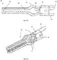
- the blademay function to cut a feature of interest.
- the blademay be any cutting tool that may be used in surgery, for example laparoscopic surgery.
- the blademay be any cutting device that may be extended and retracted through the tubular member.
- the blademay be made of any material that may be sharpened; is strong enough to cut a feature of interest; is biocompatible; that may conduct electricity; or a combination thereof.
- the blademay be any shape so that the blade may fit inside the tubular member and extend into the gap formed between the two opposing jaws, between two legs connected to a jaw, or both so that a feature of interest may be cut.
- the blademay be substantially solid along its length.
- the blademay have a length so that the blade is sufficiently long to cut a feature of interest.
- the maximum length of the blademay be equal to the length of the jaws.
- the length of the blademay be substantially equal to that of the protrusions of the camming shaft.
- the length of the blademay be less than that of the protrusions.
- the blademay include one or more recesses.
- the blademay include a pin recess so that a spacing member, a pin, or both may extend through the blade and the blade may still axially move.
- the pin recessmay function to allow the blade to axially move.
- the pin recessmay be a through hole in the blade.
- the pin recessmay have a shape that is substantially identical to that of the spacing member, a pin, or both.
- the pin recessmay be round, oval, a slot, a slit, or a combination thereof.
- the pin recessmay function to allow the blade to fully extend when the jaws are open, the jaws are closed, or a position therebetween.
- the pin recessmay have a length that is substantially equal to the axial movement of the tubular member, the jaws, or both.
- the blademay be sufficiently small so that the blade may be housed in the tubular member during movement, insertion, or both.
- the blademay be extended into, and retracted from, the gap in the two opposing jaws.
- the distal end of the blademay have a shaped edge.
- the proximal end of the blademay be attached to a blade shaft.
- the blade shaftmay function to support the blade and assist in moving the blade axially.
- the blade shaftmay extend the blade axially along the axis of the tubular member, the tubular member, or both and out of the tubular member, tubular member, or both (e.g., into the gap formed by the two opposing jaws).
- the blade shaftmay function to extend and/or retract the blade via an operable mechanism.
- the blade shaftmay be used to actuate a blade during surgery.
- the blade shaftmay be of shape and size to actuate a blade inside a tubular member.
- the blade shaftmay be a wire, shaped metal, a rod, a plurality of combined longitudinal pieces, or any similar rigid structure that may fit in and extend through the tubular member.
- the blade shaftmay be made of a material that is lightweight, but strong enough to extend a blade through a feature of interest thereby cutting the feature of interest.
- the blade shafthas a distal end and a proximal end.
- a blademay be attached to a distal end, a distal end region, or both of the blade shaft.
- the blade shaftmay have a structure at the proximal end of the blade shaft, at the proximal end region of the blade shaft, or both to assist in rotation of the blade inside of the stylet, tubular member, or both.
- the stylet as discussed hereinmay include a tubular member or may be the tubular member.
- the styletmay include a tubular member and an inner tube.
- the styletmay include a tubular member that extends around all or a portion of an inner tube.
- the tubular membermay function to extend into a patient during a surgical procedure so that a user (i.e., surgeon) can perform one or more surgical procedures.
- the tubular membermay be flexible so that the tubular member may be moved within a patient.
- the tubular membermay be substantially rigid so that the tubular member may be moved to a desired location.
- the tubular memberincludes a distal end and a proximal end.
- the distal endmay be an end of the tubular member that is located farthest from the hand piece (e.g., the end of the tubular member that is inserted into a patient).
- the proximal end of the tubular membermay be the end of the tubular member located proximate to the user, in the hand piece, or both.
- the proximal endmay extend into the hand piece so that manipulation of the one or more operable mechanisms manipulates the tubular member.
- the tubular member and its componentsmay be made of any biocompatible material, for example, stainless steel, plastic, a synthetic material, a natural material, or a combination thereof.
- the tubular membermay comprise a tubular member sub-assembly.
- the tubular member sub-assemblymay include one or more hollow tubes, one or more inner tubes, one or more outer tubes, one or more gripping assemblies, one or more cutting assemblies, one or more rotation mechanisms, one or more operable mechanisms, one or more camming shafts, one or more guides, one or more spacing members, or a combination thereof.
- the one or more outer tubesmay function to close the jaws, bias the jaws, or both.
- the one or more tubesmay function to bias the actuation mechanisms that bias the jaws.
- the one or more tubesmay function to protect the inner tube.
- the one or more jawsmay move relative to the inner tube.
- the one or more jawsmay axially move towards the distal end and the proximal end during movement.
- the one or more jawsmay overrun the inner tube, the jaws, the arcuate sections, or a combination thereof to bias the jaws towards each other.
- the one or more inner tubesmay function to create a point of contact for one or more jaws.
- the one or more inner tubesmay function to connect to a camming shaft.
- the one or more inner tubesmay function to extend through all or a portion of the tubular member.
- the one or more inner tubesmay form a connection point, include a connection feature (e.g., a pin, bolt, screw, rivet, or a combination thereof) for one or more jaws.
- the one or more inner tubesmay connect to a pivot joint of one or more jaws so that the one or more jaws rotate about an axis.
- the one or more inner tubesmay assist in opening and closing the jaws.
- the one or more inner tubesmay be located distal of one or more hollow tubes.
- the one or more inner tubesmay be part of a tubular member.
- the one or more inner tubesmay be movable relative to an outer tube.
- the one or more inner tubesmay be axially movable, rotationally movable, or both relative to an outer tube, a camming shaft, or both.
- the one or more inner tubesmay be static and an outer tube may be movable relative to the inner tube.
- the one or more inner tubesmay be substantially the same length as an outer tube.
- the one or more inner tubesmay be shorter than an outer tube.
- the one or more inner tubesmay be in communication with a camming shaft.
- the one or more inner tubesmay receive all or a portion of a hollow tube.
- the one or more inner tubesmay be located between a tubular member and a hollow tube.
- the one or more tubular membersmay include and/or be one or more hollow tubes and the one or more hollow tubes (e.g., an inner tube, an outer tube, or both) may function to house one or more working components (e.g., a gripping assembly, a cutting assembly, or both).
- the one or more tubular membersmay function to house all or a portion of one or more functional members (e.g., inner tube, blade, jaws).
- the one or more tubular membersmay be any device that may be used to extend a forceps device and any assemblies into a patient.
- the one or more tubular membersmay assist in actuating a gripping assembly.
- the one or more tubular membersmay be a cannula.
- the one or more tubular membersmay be flexible.
- the one or more tubular membersmay include a curve, a bend, or a combination thereof.
- the one or more tubular membersmay be rigid. More preferably, the one or more tubular members are generally linear and are substantially rigid.
- the one or more tubular membersmay be any hollow tube shaped structure that may rotate around a longitudinal axis, its own longitudinal axis, or both.
- the one or more tubular membersmay include a distal end and a proximal end.
- the one or more tubular membersmay include an inner circumscribed diameter and an outer circumscribed diameter.
- the one or more tubular membersmay include a main body with a consistent inner and outer circumscribed diameter and a tapered portion with a larger outer circumscribed diameter than the main body.
- the one or more tubular members, the camming shaft, or bothmay include one or more segments that are square, rounded, oval, irregular, or any shape that allows for the circumscribed diameter of the one or more tubular members to increase and that may allow for rotation around a longitudinal axis, or a combination thereof.
- the one or more tubular membersmay include an inner cross-sectional dimension that assists in the functioning of the one or more assemblies.
- the inner cross-sectional dimensionmay be about 1 mm or more, preferably 3 mm or more, more preferably 5 mm or more.
- the inner circumscribed diametermay be about 20 mm or less, preferably about 15 mm or less, or more preferably about 10 mm or less.
- the inner circumscribed diametermay from about 1 mm to about 20 mm, preferably from about 3 mm to about 15 mm, or more preferably from about 5 mm to about 10 mm.
- the inner cross-sectional dimensionmay vary from location to location within the one or more tubular members and/or camming shaft.
- the tubular member and/or camming shaftmay have a largest cross-sectional dimension and a smallest cross-sectional dimension.
- the largest inner cross-sectional dimensionmay be a factor of 2 or more, 3 or more, 4 or more, or even 5 or more times that of the smallest inner cross-sectional dimension.
- the inner cross-sectional dimensionmay be substantially the same size as one or more jaw shafts, one or more legs of a jaw, two jaw shafts, two or more legs of a jaw, a blade, or a combination thereof.
- the inner cross-sectional dimensionsmay vary to accommodate one or more jaw shafts, leg of a jaw, one or more blades, one or more blade shafts, or a combination thereof.
- a gripping assembly, a blade assembly, or bothmay extend through the inner cross-sectional dimension of the one or more tubular members, the camming shaft, the camming shaft, or a combination thereof.
- the tubular membermay be substantially circular, substantially oval, or both along all or a portion of its length.
- the tubular membermay be substantially circular from a proximal end to a region approaching the distal end region.
- the tubular membermay include one or more contour features toward the distal end region.
- the one or more contoured featuresmay laterally contain movement of the jaws so that the jaws are forced together, towards a center plane (e.g., a plane that extends substantially down the center of the camming shaft and/or tubular member, a plane that extends between two opposing jaws, or both), or both.
- the geometry of the one or more contoured featuresmay affect how the jaws are moved.
- the distal end regionmay include one or more contour features that vary the size, shape, geometry, orientation, or a combination thereof of the distal end region.
- the one or more contour featuresmay create a flat surface on the outside of the tubular member; may include one or more flat walls on the inside or outside of the tubular member; may include arcuate segments that are non-continuous so that a non-circular, non-linear surface is formed; or a combination thereof.
- the distal end, distal end region, or both of the camming shaft, the tubular member, or bothare non-circular, have non-circular portions, or both.
- the one or more contour featuresmay be one or more flat portions, one or more scalloped portions, one or more blade recesses, one or more pocket surfaces, one or more protrusions, one or more molded flares, one or more side walls, or a combination thereof, and each of the contour features discussed herein may be applied to the tubular members, the hollow tubes, the camming shaft, or a combination thereof.
- the camming shaft and/or tubular membermay be square in shape.
- the tubular member, camming shaft, or bothmay include one or more flat surfaces and/or flattened surfaces located on the inside and/or outside of the tubular member and/or camming shaft.
- the tubular member, camming shaft, or bothmay only include one or more flat surfaces on the inside.
- the flat surfacesmay be located anywhere along the length of the tubular member and/or camming shaft.
- the flat surfacesare located in a distal end region.
- the flat surfacesmay be located outside of the distal end region.
- the distal end regionmay be generally circular and a region on a proximal side of the distal end region may include one or more flat surfaces.
- the flat surfacesmay be located on one or more adjacent walls.
- the flat surfacesare located on opposing sides.
- the flat surfacesmay be located within the tubular member and/or camming shaft so that a jaw having two or more legs and/or shafts has one leg and/or shaft in contact with one flat surface and another leg and/or shaft in contact with a different flat surface.
- both legs and/or shaftsmay both be in contact with a single flat surface.
- the tubular member, camming shaft, or bothmay include one or more, two or more, three or more, four or more, six or more, eight or more, or even ten or more flat surfaces.
- the flat surfacesmay extend around an inside of the tubular member and/or camming shaft so that the tubular member and/or camming shaft has a triangular shape, square shape, rectangular shape, pentagonal shape, hexagonal, heptagonal, octagonal, decagonal, or a combination thereof.
- the flat surfacesmay be spaced apart. For example, two adjacent flat surfaces may be separated by a blade recess.
- the flat surfacesmay be connected together by arcuate surfaces, other flat surfaces, concave portions, convex portions, or a combination thereof.
- the one or more tubular members and/or camming shaftsmay be free of, without, exclude, or a combination thereof flat surfaces.
- the tubular members and/or camming shaftinclude flat surfaces and arcuate surfaces to form one or more scalloped portions.
- the one or more scalloped portionsmay function to control movement of the one or more legs, one or more jaw shafts, or both.
- the one or more scalloped portionsmay constrain the one or more legs, the one or more jaw shafts, or a combination of both.
- the one or more scalloped portionsmay move two opposing legs, one or more jaw shafts, or both towards each other when the jaws are being actuated, thereby resisting lateral or outward movement of the two opposing legs, one or more jaw shafts, or both with respect to the scalloped portions.
- the scalloped portionsmay extend towards a center of the tubular member from an outer edge and/or circumference of the tubular member.
- the scalloped portionsmay extend around a portion of the one or more blades.
- the scalloped portionsmay become more constraining as the scalloped portion extends towards the distal end.
- the scalloped portionsmay be substantially the same dimensions along the length of the scalloped portion.
- the scalloped portionsmay be generally concave and extend inward from an outer edge of the tubular member and/or camming shaft.
- the scalloped portionsmay reduce the distance from one side of the tubular member and/or camming shaft to the other side relative to an area that does not include the scalloped portion.
- the scalloped portionsmay guide the blade through a gap in the jaws, a gap between the jaws, or both.
- the one or more scalloped portionsmay form a pockets and/or pocket surface.
- the one or more pocket surfacesmay function to guide one or more legs, one or more jaw shafts, or both.
- the one or more pocket surfacesmay function to assist in closing the one or more jaws, creating a gripping force, or both.
- the one or more pocket surfacesmay align one jaw relative to another jaw.
- Each leg and/or jaw shaftmay be at least partially surrounded by its own pocket surface (e.g., at least about 90 degrees or more, about 120 degrees or more, or even about 180 degrees or more of each leg and/or jaw shaft is in contact with a pocket surface).
- the pocket surfacemay substantially mirror the shape of each leg and/or jaw shaft.
- the pocket surfacemay only extend around one side of each leg and/or jaw shaft and the opposing side may be free of a pocket surface so that each leg and/or jaw shaft is free to move towards and/or into contact with an opposing leg and/or jaw shaft.
- the pocket surfacesmay be connected by flat portions (e.g., linear portions).
- the hollow tube, tubular member, camming shaft, or a combination thereofmay include one or more pocket surfaces that have an inner cross-sectional dimension that is substantially the same length as that of the jaw shafts and/or legs of the jaws (i.e., the distance from one side of a pocket surface to the other side of the pocket surface may be substantially the same as the combined largest dimension of the legs of the jaws, jaw shafts, or both).
- the one or more pocket surfacesmay include a blade recess that separates one or more pocket surfaces from another of the one or more pocket surfaces.
- the one or more blade recessesmay function to guide the blade through the tubular member, the camming shaft or both.
- the one or more blade recessesmay prevent the blade from contacting the jaws, the legs, the jaw shafts, or a combination thereof.
- the one or more blade recessesmay substantially mirror the shape of the blade.
- the one or more blade recessesmay include one or more flat portions, one or more arcuate portions, or both.
- the one or more blade recessesmay extend along a center plane.
- the one or more blade recessesmay include a space so that a portion of each of the legs, each of the jaw shafts, or both extend at least partially into the blade recess.
- the one or more blade recessesmay be a gap in a flat portion, a flat wall, or both.
- the one or more blade recessesmay be at any location along the tubular member, the camming shaft, or both. Preferably, the blade recess is located within the distal end region of the tubular member, the camming shaft, or both.
- the one or more blade recesses, one or more contour features, or bothmay be used in conjunction with and/or be placed relative to one or more guides.
- the one or more guidesmay be any device that supports one or more legs, one or more shafts, one or more wires, one or more functional elements, or a combination thereof as they extend from a proximal end to a distal end.
- the one or more guidesmay support a control portion of one or more functional elements (i.e., a portion that is actuated or actuates to create a predetermined result).
- a leg of a jawmay extend through the guide and the guide may provide support and/or isolation so that the leg of one jaw is not intertwined and/or damaged by a leg of another jaw.
- the one or more guidesmay prevent bending, kinking, coiling, intertwining, damage, or a combination thereof as elements extend through the tubular member.
- the one or more guidesmay include one or more through holes for guiding one or more members.
- the one or more through holesmay be a one or more blade shaft guides, one or more jaw shaft guides, one or more functional element shaft guides, or a combination thereof.
- the one or more guidesmay be used in conjunction with the one or more contour features in the distal end region of the tubular member, the camming shaft, or both.
- the one or more guidesmay allow for substantially all of an axial force to be translated axially through the tubular member.
- the one or more guidesmay restrict the cross-sectional area of the tubular member along the longitudinal axis of the tubular member.
- the one or more guidesmay extend along the length of the tubular member.
- the one or more guidesmay extend along the length of the tubular member and stop before reaching the distal end region.
- the one or more guidesmay have a length that is about 85 percent or less, about 75 percent or less, about 60 percent or less than the tubular member.
- the tubular membermay work with one or more features of the tubular member, the camming shaft, or both.
- the tubular membermay include, be connected to, be used in conjunction with, be located adjacent to, or a combination thereof one or more camming shafts.
- the one or more camming shaftsmay function to change the shape, configuration, geometry, orientation, or a combination thereof of the one or more tubular members.
- the one or more camming shaftsmay be a device that is put in, connected to, fit with, or a combination thereof a distal end region.
- the one or more camming shaftsmay constrain the cross-sectional area of the tubular member.
- the one or more camming shaftsmay restrict the jaws, the legs of the jaws, the jaw shafts, the arcuate sections, or a combination thereof.
- the one or more camming shaftsmay assist in forming a gripping force, a desiccation force, or a combination thereof.
- the one or more camming shaftsmay include any of the contour features discussed herein for the tubular member and vice versa.
- the one or more camming shaftsmay be connected to the tubular member by friction fit, adhesive, welding (e.g., laser or spot), crimping, a detent, a fastener, an interference fit, threads, or a combination thereof.
- the one or more camming shaftsmay include one or more connection features (i.e., a portion that is raised above the remainder of the camming shaft).
- the one or more camming shaftsmay include a complex geometry and may vary the geometry of a standard tubular member.
- a standard tubular membermay be created for all applications and a scalloped portion may be added to one tubular member and a pocket surface may be added to a different tubular member by selecting and installing a camming shaft with those features.
- the one or more camming shaftsmay be installed within the distal end region of the tubular member so that the distal end region has a changed geometry. However, the one or more camming shafts may extend to a proximal side of the distal end region.
- the one or more camming shaftsmay be made of any biocompatible material.
- the one or more camming shaftsmay be made of plastic, a polymer, metal, steel, surgical steel, stainless steel, or a combination thereof.
- the one or more camming shaftsmay be made of a material that may be formed by molding (e.g., insert molding, blow molding, injection molding, or a combination thereof).
- the camming shaftmay be molded directly to the tubular member.
- the camming shaftmay be connected to the tubular member so that substantially all of the camming shaft is located within the tubular member.
- the camming shaftmay form the distal end region of the tubular member.
- the camming shaftmay have a portion that is connected to and extends from the tubular member.
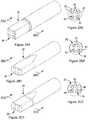
- the camming shaftmay include one or more protrusions that extend proximal into the tubular member.
- the one or more protrusionsmay function to connect the camming shaft to a distal end of a tubular member so that the camming shaft forms the distal end region of the tubular member.
- the one or more protrusionsmay function to guide one or more elements (e.g., a jaw shaft, a leg, a blade shaft, a functional element shaft, or a combination thereof) through the tubular member, into the camming shaft, or both.
- the one or more protrusionsmay function to provide axial stiffness to the tubular member.
- the one or more protrusionsmay assist in connecting the one or more camming shafts to the tubular member.
- the one or more camming shaftsmay be free of protrusions, exclude protrusions, be without protrusions, or a combination thereof.
- the one or more protrusionsmay be connected to an end region of the camming shaft, a molded flare, or both.
- the one or more molded flaresmay function to extend into a tip of a tubular member, connect the camming shaft to the tubular member, reduce the cross-sectional area of a distal end region of the tubular member, or a combination thereof.
- the one or more molded flaresmay form a step in the camming shaft.
- the one or more molded flaresmay adapt the camming shaft to fit within one or more tubular members.
- the one or more molded flaresmay form a series of steps that allow the camming shaft to be inserted into and/or connected to tubular members having a different diameter and/or cross-sectional area.
- the one or more molded flaresmay connect the camming shaft to the tubular member so that the outside cross-sectional length of the tubular member and the camming shaft are substantially equal, so that a lip is not formed between the camming shaft and the tubular member, or both.
- the outer walls of the camming shaftmay be generally circular, a geometric shape, symmetrical, asymmetrical, or a combination thereof.
- the one or more camming shaftsmay be free of one or more molded flares, exclude a molded flare, or both.
- the outer walls of the camming shaftmay have any of the features discussed herein for the shape of the tubular member.
- the outer walls and the inner walls of the camming shaftmay have a different configuration.
- the camming shaftmay include one or more of the contour features as are discussed herein.
- the one or more contour featuresmay be one or more side walls.
- the one or more side walls of the camming shaftmay perform any of the functions and/or include any of the structure discussed herein for the flat portion of the tubular member.
- the one or more side wallsmay be contoured, angled, flat, parallel, adjacent, in contact with one or more legs and/or jaw shafts, or a combination thereof.
- the one or more side wallsmay include one or more coatings.
- the one or more coatingsmay provide electrical insulation between the stylet, tubular member, or both and the legs, jaw shaft, or both.
- the one or more side wallsmay be formed of a different material than the camming shaft.
- the one or more side wallsmay be connected to, molded on, attached to, adhered to, fastened to, or a combination thereof to the camming shaft.
- the one or more side wallsmay be padded.
- the lateral side wallsonly are padded.
- the one or more side wallsmay be made of and/or include a polymer, plastic, elastomer, or a combination thereof.
- the padding on the one or more side wallsmay be low friction, high friction, hard, soft, a dampening material, or a combination thereof.
- the one or more side wallsmay extend along an inside of the camming shaft, onto an ear of the camming shaft, on a flare, on the protrusions, or a combination thereof.
- the one or more earsmay function to extend the camming shaft in a distal direction.
- the one or more earsmay function to create a blunt surface, a surface with a smaller area, or both.
- the one or more earsmay provide axial stiffness, radial stiffness, longitudinal stiffness, or a combination thereof to the camming shaft, the tubular member, or both.
- the shape of the earsmay be varied depending on structural strength requirements of the camming shaft.
- the shape of the earsmay include more structure and/or material than other shapes of the ears.
- the one or more earsmay be shaped so that any contact between the ears and tissue does not damage tissue.
- the one or more earsmay be an integral part of the camming shaft. The ears may lengthen the distal end region.
- the earsmay extend out of and/or from a distal end of the camming shaft, the tubular member, or both.
- the earsmay be located on the lateral sides of the camming shaft.
- the earsmay be located so that the jaws open and close without interference from the ears.
- the one or more earsmay be square, circular, oval, include a blunt distal end, include an arcuate distal end, or a combination thereof.
- the one or more earsmay be made of a material that provides axial stiffness to the tubular member, the camming shaft, or both.
- the one or more earsmay include a material on the inside of the camming shaft so that the ears support one or more spacing members.
- the one or more camming shaftsmay be free of ears, exclude ears, or both.
- the one or more earsmay include one or more spacing members, be located proximate to one or more spacing members, or a combination thereof.
- the one or more spacing membersfunction to separate the jaws.
- the one or more spacing membersmay function to separate the jaws when the jaws and/or tubular member is retracted to a starting position, when the jaws and/or tubular member is over retracted (i.e., a position past the starting position).
- a starting positionis considered a zero position and over retracted is considered a negative position (e.g., -1 or more, -2 or more, -5 or more).
- the one or more spacing membersmay be located at a distal end of the stylet, tubular member, inner tube, or a combination thereof.
- the one or more spacing membersmay be located distal to a connection feature for a pivot joint (e.g., a pin).
- the one or more spacing membersmay work in conjunction with a connection feature for connecting a pivot joint to the stylet, inner tube, tubular member, or a combination thereof.
- the one or more connection featuresmay form a connection with the stylet and the one or more spacing members may rotate the jaws outward (e.g., open) about the connection features.
- the one or more spacing membersmay separate the jaws at a neutral position, a starting position, or both.
- the one or more spacing membersmay separate the jaws so that the jaws may be used for dissection, separating tissue, or both.
- the one or more spacing membersmay assist in moving tissue, spreading tissue apart, or both.
- the jaws when pressed against the spacing membersmay create a force of about 1 N or more, about 2 N or more, about 3 N or more, or even about 5 N or more. Stated another way, the jaws may resist closing when a force of about 1 N or more, 2 N or more, 3 N or more, or even about 5 N or more.
- the one or more spacing membersWhen the one or more spacing members are in contact with the two or more jaws the spacing members prevent the jaws from closing by external forces.
- the one or more spacing membersmay be a single spacing member that extends across the opening of the tubular member, the camming shaft, or both.
- the one or more spacing membersmay be a biasing member that creates a positive force against one or both of the jaws so that the jaws are forced apart.
- the one or more biasing membersmay function to create a force so that a default position of the jaws is open.
- the one or more biasing membersmay be located in contact with the jaws, the jaw shafts, the arcuate sections, a heel, or a combination thereof.
- the one or more biasing membersmay be a spring, an elastic material, an expandable material, an elastically deformable material, a bent piece of metal, a helically wrapped material, or a combination thereof.
- the one or more spacing membersmay be two spacing members and the two spacing members may extend from opposing sides towards a center, a central plane, or both of the tubular member, camming shaft, or both. The one or more spacing members may alter the pressure exerted by the jaws.
- the one or more spacing membersmay alter the pressure exerted from a front of the spacing member to a heel of the spacing member or vice versa depending upon the location of the spacing members, the shape of the spacing members, or both.
- the one or more spacing membersmay provide for an even distribution of force along the surface of the jaws relative to jaws that do not include the spacing members.
- the one or more spacing membersmay be shaped so that the spacing members are free of contact, free of interference, or both with the jaws when the jaws are closed, a gripping force is created, or both.
- the one or more spacing membersmay be connected to the tubular member, the camming shaft, or both.
- the one or more spacing membersmay be connected by an adhesive, threads, welding (e.g., spot or laser), a fastener, or a combination thereof.
- the one or more spacing membersare at a location so that when the jaws are closed the spacing member aligns with the arcuate sections.
- the one or more spacing membersmay have a uniform shape, a tapered shape, one shape on a distal side and a different shape on a proximal side, or a combination thereof. Any of the spacing members discussed herein may include one or more tapered portions. The tapered portions may allow for axial movement of the jaws without interference with the jaws, shafts, jaw shafts, legs, or a combination thereof.
- the tapered portionsmay extend at a low angle to a point.
- the tapered portionsmay be one or more tapered portions.
- the one or more tapered portionsmay be one or more fillets.
- the one or more filletsmay be a plurality of fillets that are interconnected to form the tapered portion.
- the tapered portionsmay extend at a steep angle and have a blunt end.
- the tapered portionsmay be located on the distal side, the proximal side, or both of the spacing members.
- the tapered portionsmay extend at an angle of about 5 degrees or more, about 10 degrees or more, about 15 degrees or more, or even about 25 degrees or more.
- the tapered portionmay extend at an angle of about 90 degrees or less, about 75 degrees or less, or about 60 degrees or less.
- the shape of the spacing membermay change across the cross-sectional length of the spacing members.
- the spacing membermay continuously extend across the cross-sectional length of the tubular member, the camming shaft, or both.
- the spacing membermay be two or more discrete pieces and may be connected in two or more locations to the tubular member, the camming shaft, or both.
- the spacing membersmay have any shape that assists in separating the jaws, using the jaws for dissection, or both.
- the spacing membersmay be a pin, a crimp, a bar, include a bulbous portion, a mushroom pin, a tapered portion, or a combination thereof.
- the one or more pinsmay substantially span the cross-sectional length of the camming shaft, the tubular member, an inner tube, or a combination thereof.
- the one or more pinsas discussed herein, may be used both as a connection feature and a spacing member.
- the one or more pinsmay be two pins that are separated by a gap.
- the one or more pinsmay extend through a pin recess in the blade.
- the one or more pinsmay be round, extend from an ear, form a distal most point of the tubular member, or a combination thereof.
- the one or more pinsmay form a common axis.
- the one or more pinsmay form a common axis for the two or more jaws.
- the two or more jawsmay rotate about the pin.
- the one or more pinsmay be uniform in shape. When more than one pin is used the pins may be identical.
- the one or more pinsmay be a mushroom pin.
- the one or more pinsmay include a mushroom portion.
- the mushroom portionmay function to prevent the legs, jaws, jaw shaft, or a combination thereof from extending towards a center, a central portion, or both of the tubular member.
- the mushroom shapemay prevent the legs, jaw shafts, or both from contacting each other, the blade, or both.
- the mushroom shapemay provide a space for the blade to extend through the tubular member without pressure being exerted by the legs, jaw shafts, or both.
- the mushroom portionmay be a part of the pin that is expanded relative to the rest of the pin.
- the mushroom portionmay be a portion that 1.2 times or more, 1.3 times or more, or even 1.5 times or more the size of the non-mushroom portion of the pin.
- the mushroom portion of the mushroom pinmay be located substantially in the center of the camming shaft, the tubular member, or both.
- the mushroom pinmay be substantially the same as a head on a screw, nut, bolt, the like, or a combination thereof.
- the mushroom pinmay be integrally molded.
- the mushroom pinmay be a discrete piece added to the camming shaft, the tubular member, or both.
- the one or more tubular members, the one or more camming shafts, or bothmay be free of a pin.
- the one or more tubular members, the one or more camming shafts, or bothmay include an integrally formed portion such as a crimp.
- the one or more crimpsmay function to perform the functions of a spacing member.
- the one or more crimpsmay be a unitary part of the tubular member, the camming shaft, or both.
- the one or more crimpsmay be formed.
- the one or more crimpsmay be material folded upon itself.
- the one or more crimpsmay be a part that extends in a distal direction from the camming shaft and is formed to extend inward (i.e., in a lateral direction) and is folded together.
- the one or more crimpsmay be folded so that the crimps are solid, include a recess, is hollow, or a combination hereof.
- the one or more crimpsare cut and folded to extend from and across the tubular member and form a frontal bar.
- the one or more crimpsmay be varied in size depending on the cross-sectional thickness of the tubular member, camming shaft, or both.
- a standard camming shaft with crimping materialmay be created and the shape and size of the crimp may be varied depending upon the tubular member, the legs, the jaw shaft, or both being used.
- the crimpmay be one solid piece that extends across opening of the tubular member, the camming shaft, or both.
- the one or more crimpsmay extend from an outside edge of the tubular member, the camming shaft, or both.
- the one or more crimpsmay extend from within the tubular member, the camming shaft, or both.
- the crimpmay be two discrete pieces that extend from opposing sides.
- the spacing membermay be a longitudinally extending bar.
- the one or more barsmay perform the function of any of the spacing members discussed herein.
- the one or more barsmay extend from an inside of the tubular member, the camming shaft, or both.
- the one or more barsmay extend substantially the length of the camming shaft.
- the one or more barsmay extend from a central portion of the camming shaft axially out an opening in camming shaft.
- the one or more barsmay be substantially planar along their length.
- a portion of the one or more barsmay be substantially planar and a portion of the one or more bars may be bulbous.
- a portion of the one or more bars located within the camming shaft, the tubular member, or bothmay be planar and a portion located outside of the camming shaft may form a bulbous portion.
- the barmay gradually increase in size as the bar extends in the distal direction.
- the barmay terminate at a bulbous portion.
- the bulbous portionmay be substantially the largest portion of the one or more bars.
- the bulbous portionmay gradually become thicker than a main portion of the bar.
- the bulbous portionmay be a step change from the main portion of the bar.
- the bulbous portionmay have an upper portion and lower portion and the upper portion and the lower portion may be mirror images of each other.
- the bulbous portionmay substantially mirror the shape of the arcuate sections of the jaws.
- the upper portion and the lower portionmay be equal in size so that a jaw extending over the top of the upper portion and a jaw extending under the bottom of the lower portion moves the jaws an equal distance outward.
- the one or more barsmay be integrally connected to the camming shaft, the tubular member, or both.
- the one or more barsmay be integrally formed with formation of the camming shaft, the tubular member, or both.
- a cross-section of the bulbous portion of the barmay have a tear drop shape.
- a cross-section of the bulbous portion of the barmay have one portion that is a factor of 2 or more, 3 or more, or even 4 or more larger than the rest of the bar.
- FIG. 1illustrates a side view of an example of laparoscopic forceps 2.
- the laparoscopic forceps 2include a handpiece 4 having a distal end 6 and a proximal end 8.
- the handpiece 4also includes at least one operable mechanism 50.
- a tubular member 20has a proximal end 24 that is connected to the distal end 6 of the handpiece 4.
- the tubular member 20includes a distal end 22 that includes jaws 40 extending therefrom.
- the jaws 40have arcuate segments 42 that open and close the jaws 40 when the tubular member 20 is moved forward along the longitudinal axis 26 of the tubular member into contact with the arcuate segments 42 or the jaws 40 are moved backwards along the longitudinal axis 26 into contact with the tubular member 20.
- Figure 2A1illustrates a perspective view of a tubular member 20.
- the tubular member 20includes a distal opening 28 for legs of the jaws and the jaws 40 (not shown) to extend from the tubular member 20.
- Figure 2A2illustrates a cross-sectional view of the tubular member 20 of Figure 2A1 along lines 2A2-2A2.
- the tubular member 20is generally square in shape and includes top and bottom flat portions 30 and opposing flat side wall portions 30.
- the legs of the jaws 44extend through the tubular member 20 and the square shape of the tubular member 20 constrains the legs of the jaws 44 so that axial movement of the legs 44 within the tubular member 20 closes the jaws (not shown) reliably one on top of the other.
- Figure 2B1illustrates a perspective view of a tubular member 20.
- the tubular member 20includes a distal opening 28 for legs of the jaws and the jaws 40 (not shown) to extend from the tubular member 20.
- Figure 2B2illustrates a cross-sectional view of the tubular member 20 of Figure 2B1 along line 2B2-2B2.
- the tubular member 20is generally oblong in shape and includes top and bottom flat portions 30 in a distal region.
- the legs of the jaws 44extend through the tubular member 20 and the flat portions 30 of the tubular member 20 constrains the legs of the jaws 44 so that axial movement of the legs 44 or the tubular member 20 closes the jaws (not shown) reliably one on top of the other.
- Figure 2C1illustrates a perspective view of a tubular member 20.
- the tubular member 20includes a distal opening 28 for legs of the jaws and the jaws 40 (not shown) to extend from the tubular member 20.
- Figure 2C2illustrates a cross-sectional view of the tubular member 20 of Figure 2C1 along line 2C2-2C2.
- the tubular member 20is generally oblong in shape and includes top and bottom scalloped portions 32.
- the legs of the jaws 44extend through the tubular member 20 and the scalloped portions 32 of the tubular member 20 constrains the legs of the jaws 44 so that axial movement of the legs 44 or the tubular member 20 closes the jaws (not shown) reliably one of top of the other.
- Figure 3illustrates an example of an end of the tubular member 20 or a camming shaft that may be placed within the tubular member 20.
- the tubular member 20includes a pair of internal flat portions 30 along the top surfaces and the bottom surfaces.
- a blade recess 34extends between the pair of internal flat portions 30 so that a blade (not shown) extends out of the tubular member 20.
- Figure 4illustrates a cross-sectional view of a tubular member 20.
- the tubular member 20includes a plurality of pocket surfaces 36.
- the plurality of pocket surfaces 36include at least a portion that has a complementary shape to that of the legs of the jaws 44 so that as the tubular member 20 or the legs 44 axially move the pocket surfaces 36 control the orientation and movement of the jaws (not shown).
- a blade recess 34extends between the pocket surfaces 36 so that the blade (not shown) extends through the distal opening 28 of the tubular member.
- Figure 5illustrates a side view of the tubular member 20 of Figure 4 . As shown, the tubular member 20 has a distal opening 28 at one end.
- Figure 6illustrates another example of a cross-sectional view of a tubular member 20.
- the tubular member 20includes a blade recess 34 down the center between the legs of the jaws 44.
- the tubular member 20includes a pocket surface 36 for receiving each of the legs of the jaws 44.
- Figure 6 as illustratedis taken at a different cross-sectional location as Figure 4 , however, Figure 4 may be taken at the same cross-sectional location as Figure 6 .
- FIG. 7illustrates a perspective view of one example of a camming shaft 70 that is inserted into a tubular member (not shown).
- the camming shaft 70includes a molded flare 74 with a pair of protrusions 72 extending therefrom.
- Figure 8illustrates a side view of the camming shaft 70 with a molded flare 74 and a pair of protrusions 72 extending from the molded flare 74.
- FIG. 9illustrates a top view of the camming shaft 70.
- the camming shaftincludes a molded flare 74 with a pair of protrusions 72.
- Each of the protrusions 72include a sidewall 76.
- Figure 10illustrates an end view of a camming shaft 70.
- the sidewalls 76 of the camming shaft 70have a flat portion 30 on the inside of the camming shaft 70.
- Figure 11illustrates a camming shaft 70 located on the laparoscopic forceps 2 with the jaws 40 extending therefrom.
- the jaws 40include a pair of arcuate sections 42 that are biased by the camming shaft 70 so that the jaws 40 are opened and closed.
- Figure 12illustrates a side view of jaws 40 including a spacing member located between the jaws.
- the jaws 40include a heel 46 and a front 48. Proximate to the heel 46 are a pair of opposing arcuate segments 42 that close the opposing jaws 40 when the shaft 20 is moved into contact with the opposing jaws 40.
- a spacing member 90located on a camming shaft 70 moves the jaws 40 apart.
- the spacing member 90is a pair of pins 92 that extend from the camming member 70.
- Figure 13illustrates a perspective view of the jaws 40.
- the jaws 40are closed by the tubular member 20 being moved into a forward position.
- the tubular member 20includes a camming shaft 70 with a spacing member 90.
- the spacing member 90is a pair of pins 92 that are cantilever and extend from the camming shaft 70 so that a blade recess 34 is located between the two cantilever pins 92.
- Figure 14Aillustrates a perspective view of another example of a spacing member 90.
- the spacing member 90extends from a camming shaft 70 that is connected to a tubular member 20.
- the spacing members 90are crimps 94 that are formed by folding material together.
- the crimps 94include a blade recess 34 therebetween so that a blade (not shown) can extend between the crimps 94.
- Figure 14Billustrates a plan view of an opening in the camming shaft 70.
- the camming shaft 70includes a pair of spacing members 90.
- the pair of spacing members 90are crimps 94 with a blade recess 34 extending therebetween.
- Figure 15illustrates a cross-sectional view of Figure 16 cut along lines 15-15.
- the jaws 40extend from a tubular member 20.
- the spacing member 90which is configured as a pin 92 extends directly from the tubular member 20.
- Figure 16illustrates a perspective view of the jaws 40 in an open position, according to the invention.
- the jaws 40include an arcuate segment 42 on each leg 44 of the jaw 40.
- the tubular member 20is moved into a retracted position and moves the spacing member 90 towards a proximal end so that as the spacing member 90 is moved toward the proximal end the legs 44 of the jaw 40 are moved apart and the jaws 40 are opened.
- the spacing member 90is a pair of pins 92 that extend from the tubular member 20 and have a blade recess 34 therebetween.
- FIG 17Aillustrates a perspective view of a camming shaft 70.
- the camming shaft 70includes a pair of spacing members 90 with a blade recess 34 extending between the spacing members 90.
- Each of the spacing membersinclude a bar 96 and a bulbous portion 98 that has an expanded thickness relative to the side of the bar 96.
- Figure 17Billustrates a front view of the camming shaft 70 with the spacing members 90 extending therefrom and a blade recess 34 located therebetween.
- the bulbous portion 98is shown covering the bar 96 so that the bar 96 Is not shown.
- Figure 18illustrates a cross-sectional view of the forceps 2.
- the jaws 40closed around the spacing member 90.
- the spacing member 90includes a bar 96 and a bulbous portion 98 that mirror the shape of the arcuate portion 42.
- the arcuate portion 42is being contacted by the tubular member 20 so that the jaws 40 are closed.
- the end of the tubular member 20includes a camming shaft 70 that assists in guiding the jaws 40 within the tubular member 20.
- a blade 10is shown within the tubular member 20 and extending along the legs 44.
- Figure 19illustrates a cross-sectional view of the forceps 2 of Figure 18 in an open state.
- Figure 20illustrates a perspective view of the forceps 2 with the jaws 40 in an open state.
- the tubular member 20is in a retracted position so that the spacing member is moved backwards along the legs 44 so that the mushroom pin 100 of the spacing member 90 separates the legs 44 and the jaws 40.
- Figure 21illustrates an end view of the forceps 2 of Figure 20 .
- the jaws 40 as shownextend out of a tubular member 20.
- the pair of opposing jaws 40are separated by a pair of spacing members 90 that include a mushroom pin 100 that forces the jaws 44 apart when the tubular member 20 is retracted so that the jaws 44 from an open position.
- FIG 22illustrates an exploded view of the forceps 2 of Figure 20 according to the invention.
- the forcepsinclude a tubular member 20 including a pair of opposing spacing members 90.
- the tubular member 20includes a guide 60 with a pair of jaw shaft guides 64 and a blade shaft guide 62 extending therethrough so that the jaw shafts 41 and the blade shaft 12 are guided through the tubular member 20 during movement of the opposing jaws 40.
- a pair of spacers 14are located between the tubular member 20 and the guide 60.
- the forceps 2include a blade 10 and a blade shaft 12 that are guided through and along the blade shaft guide 62.
- the jaws 40are each connected to a jaw shaft 41 that extends through a pair of jaw shaft guides 64.
- FIG 23illustrates a perspective view of a camming shaft 70.
- the camming shaft 70includes a pair of spaced apart pins 92 that extend from a sidewall 76 that include padding 78.
- Figure 24illustrates a cross-sectional view of the camming shaft 70 of Figure 23 cut along line 24-24.
- the camming shaft 70includes a pin 92 including tapered portions 102 for guiding the legs (not shown).
- Figure 25Aillustrates a side view of a camming shaft 70.
- the camming shaft 70includes an ear 80 that has a generally rectangular shape.
- Figure 25Billustrates a side view of a camming shaft 70 with an ear 80 that has a generally circular shape.
- Figure 26illustrates a tubular member 20 with a camming shaft 70 in the opening of the tubular member 20 and a pin 92 extending across the opening of the tubular member 20 and the camming shaft 70.
- a blade 10is shown with a pin recess 16 so that the pin 92 extends through the blade 12 and the blade is longitudinally movable.
- Figure 27illustrates a perspective view of an end of a distal end 6 of laparoscopic forceps 2.
- the distal endincludes a tubular member 20 connected to a pair of opposing jaws 40.
- the tubular memberincludes a spacing member 90 that is configured as a pin 92.
- the tubular memberalso includes a camming shaft 70 that includes a pin 92 extending there through.
- the pin 92 of the camming shaft 70is connected to pivot joints 52 of the jaws 40.
- the jaws 40include legs 44 that are covered with a protective cover 43 and the legs 44 have a blade track 49 extending between the legs 44. When the jaws 40 are closed the blade 10 extends through the blade track 49 to perform a cutting function.
- the blade 10includes a pin recess 16 that the pins 92 extend through so that the blade 10 is axially movable.
- Figure 28illustrates a cross-sectional view of the laparoscopic forceps 2 of Figure 27 cut along lines 28-28.
- the laparoscopic forceps 2include a tubular member 20.
- the tubular member 20has an inner tube 120 and an outer tube 122 that extends along a portion of the inner tube 120 and a blade shaft 12, and the blade 10 extends through the tubular member 20 and the inner tube 120.
- the inner tube 120includes a camming shaft 70 that has a pin 92 extending across the camming shaft 70.
- the pin 92is connected to a pivot joint 52 of the jaws 40.
- a spacing member 90 configured as a pin 92is located in front of the pin 92 of the camming shaft 70.
- the spacing member 90separates the jaws 40 when the jaws are moved distally or the tubular member 20 is moved proximally.
- the jaws 40include an arcuate section 42 in the legs 44 that assists in closing the jaws 40 when the arcuate sections 42 contact the tubular member 20.
- a blade 10is located between the jaws 40.
- FIG 29illustrates an exploded view of laparoscopic forceps 2.
- the laparoscopic forceps 2include a tubular member 20 that includes an outer tube 122 that houses an inner tube 120 and a blade shaft 12.
- the tubular member 20includes a camming shaft 70 including a spacing member 90 that is configured as a pin 92.
- the spacing member 90is located distal of a pin 92 of the inner tube 120.
- a guide 60is located within the inner tube 120.
- the guideincludes blade shaft guides 62 and a jaw shaft guide 64 that receives the blade shaft 12.
- the blade shaft 12is connected to a blade 10 that extends between a pair of opposing jaws 40.
- the pair of opposing jaws 40each include a pivot joint 52 that is connected to a pin 92 of the inner tube 120.
- Figure 30illustrates a jaw 40.
- the jaw 40includes legs 44 having an arcuate section 42 that assist in closing the jaws 40.
- the legs 44include a blade track 49 extending therebetween.
- the jaws 40include a protective cover 43 that extends from heel 46 to the front 48 of the jaws 40.
- a pivot joint 52is located at a proximate end of the jaw 40 so that the jaw 40 can pivot from an open position to a closed position.
- Figure 31illustrates a side view of a handpiece 4 of laparoscopic forceps 2 with a cover removed.
- a tubular member 20is extending from the handpiece 4.
- the tubular memberis in communication with a biasing member 150 and locking member 152 that move the outer tube 122 relative to the inner tube 120 (not shown).
- any numerical values recited hereininclude all values from the lower value to the upper value in increments of one unit provided that there is a separation of at least 2 units between any lower value and any higher value.
- the amount of a component or a value of a process variablesuch as, for example, temperature, pressure, time and the like is, for example, from 1 to 90, preferably from 20 to 80, more preferably from 30 to 70, it is intended that values such as 15 to 85, 22 to 68, 43 to 51, 30 to 32 etc. are expressly enumerated in this specification.
- one unitis considered to be 0.0001, 0.001, 0.01 or 0.1 as appropriate.
Landscapes
- Health & Medical Sciences (AREA)
- Life Sciences & Earth Sciences (AREA)
- Surgery (AREA)
- Engineering & Computer Science (AREA)
- Medical Informatics (AREA)
- Veterinary Medicine (AREA)
- Biomedical Technology (AREA)
- Heart & Thoracic Surgery (AREA)
- Nuclear Medicine, Radiotherapy & Molecular Imaging (AREA)
- Molecular Biology (AREA)
- Animal Behavior & Ethology (AREA)
- General Health & Medical Sciences (AREA)
- Public Health (AREA)
- Physics & Mathematics (AREA)
- Plasma & Fusion (AREA)
- Otolaryngology (AREA)
- Ophthalmology & Optometry (AREA)
- Surgical Instruments (AREA)
Description
- The disclosure relates to forceps with a spacing member between two opposing jaws, a tubing member with a non-circular profile, or both.
- Generally forceps may be utilized for laparoscopic surgery. The forceps may be used to control delicate movements inside a patient. These forceps may be used to grip an anatomical feature. The forceps may include a gripping assembly or a cutting assembly. The forceps may include electrical energy for use in the gripping assembly. The forceps have a pair of opposed resilient jaws that are closed against each other by pulling the jaws into a distal end of a shaft that captures a portion of the jaws that is wider than the distal end opening of the shaft so that the jaws are moved together. Similarly the shaft may be pushed over the jaws so that the jaws are moved together to create a gripping force. In both of these the shaft captures the jaws and acts as a cam that forces the jaws together to create the gripping force. Examples of some forceps with resilient jaws closed by a camming action may be found in
U.S. Patent Nos. 5,458,598 ;5,735,849 ;5,445,638 ;6,190,386 ;6,113,596 ; and6,679,882 and HALO cutting forceps, available athttp://www.olympus-osta.com/halo.htm last accessed on 4/3/2014. - Some laparoscopic forceps include jaws that have two legs that are connected at a distal end forming a gap between the two legs so that a blade can travel down the gap in center of the two opposing jaws. During the camming of the jaws, the jaws may be moved into contact with the blade creating a drag force which may prevent the blade from moving and/or may cause misalignment of the blade. Further, the camming force on the opposing jaws may not be equal and the uneven application of forces on the opposing jaws may cause the distal ends of the jaws to be misaligned during gripping.
- The laparoscopic forceps after the jaws are released and the jaws are no longer constrained by the shaft typically move apart. This opening force may be used to push apart tissue by extending the closed jaws proximate to tissue and then allowing the jaws to open so that tissue is moved. However, some of the laparoscopic forceps when released from a closed position do not have a sufficient amount of force to move tissue for dissection. Other active dissection tools allow the user to open and close the jaws through mechanical linkages. These mechanical linkages generally allow the user some control over the amount of force applied to the tissue. However, the mechanical linkages include multiple delicate parts that are difficult to assemble, are expensive, and results in a complex device to move tissue.
- It would be attractive for the forceps to include a device that controls the movement between the two opposing jaws. What is needed is a device that assists in biasing the jaws and maintains alignment of the blade. What is needed is a device that opens the jaws. It would be attractive to have a device that spreads the jaws with sufficient force so that the jaws can be used for dissection. What is needed is a device that spreads the jaws and does not interfere with a reciprocating blade
- .
WO 95/07662 A1 - The invention is defined by the independent claim and preferred embodiments are listed in the dependent claims.
- J The disclosure meets one or more of the needs by providing: a laparoscopic forceps comprising a handpiece including a distal end portion; a tubular member protruding from the distal end portion of the handpiece, the tubular member having a distal end with a distal opening, a pair of jaws having legs that are disposed within the tubular member and partially protruding from the distal opening in the distal end of the tubular member, the pair of jaws and the tubular member being movable relative to each other in a direction parallel to a longitudinal axis of the tubular member; wherein each of the pair of jaws has an arcuate section; an operable mechanism for creating relative motion between the pair of jaws and the tubular member along a direction parallel to the longitudinal axis of the tubular member, and one or more spacing members extending across the distal opening of the tubular member and between the pair of jaws; wherein the pair of jaws are closable by the relative movement of the tubular member and the pair of jaws towards each other so that the tubular member advances over the arcuate section of the pair of jaws, and the pair of jaws are openable by the relative movement of the tubular member and the pair of jaws away from each other so that the one or more spacing members extend between the pair of jaws so that the pair of jaws are moved apart.
- The disclosure provides: a laparoscopic forceps comprising: a handpiece including a distal end portion; a tubular member protruding from the distal end portion of the handpiece, the tubular member having a distal end, a pair of jaws having legs that are disposed within the tubular member and partially protruding from the distal end of the tubular member, the pair of jaws and the tubular member being movable relative to each other in a direction parallel to a longitudinal axis of the tubular member; wherein each of the pair of jaws has an arcuate section, and the pair of jaws are closable by advancing the tubular member over the arcuate section of the jaws; and an operable mechanism for creating relative motion between the pair of jaws and the tubular member along a direction parallel to the axis of the tubular member, wherein at least the distal end of the tubular member has a profile shape that is non-circular.
- A laparoscopic forceps comprising: (a) a handpiece; (b) a jaw bias mechanism; (c) a tubular member including: (i) an outer tube, and (ii) an inner tube, wherein the outer tube and inner tube are configured for relative axial motion when acted upon by the jaw bias mechanism; and (d) two or more jaws that extend out of the tubular member and the two or more jaws pivot on a common axis that is anchored to the inner tube; wherein the outer tube, during actuation of the jaw bias mechanism, overruns the two or more jaws so that the two or more jaws are moved towards bias.
- A laparoscopic forceps comprising: (1) a handpiece; (2) a jaw bias mechanism; (3) a tubular member including: (i) an outer tube, and (ii) an inner tube, wherein the outer tube and inner tube are movable relative to each other when acted upon by the jaw bias mechanism; (4) jaws extending from the tubular member and at least partially through the tubular member; and (5) a biasing element that biases the inner tube and outer tube relative to each other so that the biasing element biases the jaws open; wherein the jaws pivot on one or more axes that are anchored to the inner tube; and wherein the outer tube overruns the jaws so that the jaws are moved towards each other.
- The present teachings provide: the laparoscopic forceps include a camming shaft that is located in the distal end of the tubular member; the one or more spacing members are a pair of opposing pins that include a blade recess therebetween, one continuous spacing member that extends across the distal opening of the tubular member, or both; the one or more spacing members include a generally mushroom shape and/or are crimped material of the tubular member, the camming shaft, or both; the one or more spacing members are one or more bars that extend out of the distal opening of the tubular member along the longitudinal axis of the tubular member; the one or more bars each include a bulbous portion at an end that increases a size of each of the one or more bars so that when the bulbous portion contacts the pair of opposing jaws, the legs of the jaws, or both the jaws are moved apart; the laparoscopic forceps include a blade and the blade has a pin recess that extends along the longitudinal axis of the tubular member, and the one or more spacing members extend through the pin recess so that the blade is extendable and retractable; the jaws include a pivot joint that the jaws rotate about to open and close; an inner tube extends within all or a portion of the tubular member; a biasing mechanism for maintaining the jaws in an open state; the common axis is a pin that connects each of the two or more jaws to the tubular member; the laparoscopic forceps include a blade and the blade includes a pin recess that receives a portion of the pin so that the blade is movable along a longitudinal axis of the tubular member; a spacing member is connected to the outer tube so that the spacing member drives the jaws apart; the profile shape is part of the tubular member and the profile shape of the tubular section geometrically constrains the pair of jaws, the legs of the jaws, or both so that the jaws are moved towards each other as the tubular member is moved along the longitudinal axis of the tubular member; the profile shape is two flat sides that are generally parallel to each other; the profile shape is two opposing scalloped contours that resist lateral movement of the jaws, the legs of the jaws, or both; the scallop contours are generally half circular in shape with a maximum height at substantially a center of a length of the scalloped portion, and wherein the opposing scalloped contours extend towards each other; the profile shape is a pair of flattened surfaces on a top surface and a bottom surface and a pair of flattened surfaces on a pair of opposing side surfaces located adjacent the top and bottom surfaces, and a gap extends between the pair of flattened surfaces on the top and bottom surface and the pair of flattened surfaces on the pair of opposing side surfaces located adjacent the top and bottom surfaces; the gap is a blade recess that is sufficiently large so that a blade of the laparoscopic forceps extend longitudinally through the blade recess and out the distal end of the tubular member; substantially all of the tubular member has a generally circular cross-section and the distal end of the tubular member includes a camming shaft that creates the non-circular profile shape; the camming shaft is connected to an internal wall of the tubular member at the distal end of the tubular member; the distal end of the tubular member includes a plurality of arcuate portions that form a plurality of pockets that each extend around a portion of the jaws, the legs of the jaws, or both; a blade recess extends between at least some of the plurality of pockets; the jaws include a pivot joint that the jaws rotate about to open and close; a biasing mechanism for maintaining the jaws in an open state; a pin is connected to the outer tube that extends between the jaws so that upon movement of the outer tube axially towards a proximal end of the laparoscopic forceps, the pin moves the jaws apart; the jaws include a pivot joint and the pivot joint is connected to one or more pins that are connected to the inner tube so that the one or more axes are the one or more pins; a blade is located in the tubular member and the blade is axially movable into and out of the tubular member; or a combination thereof.
- The teachings herein provide forceps to include a device that controls the movement between the two opposing jaws. The present teachings provide a device that assists in biasing the jaws and maintains alignment of the blade. The present teachings provide a device that opens the jaws. The present teachings provide a device that spreads the jaws with sufficient force so that the jaws can be used for dissection. The present teachings provide a device that spreads the jaws and does not interfere with a reciprocating blade.
FIGS. 1 illustrates a side view of laparoscopic forceps;FIG. 2A1 illustrates a perspective view of an end of a tubular member;FIG. 2A2 illustrates a cross-sectional view of the tubular member ofFIG. 2A1 ;FIG. 2B1 illustrates a perspective view of an end of a tubular member;FIG. 2B2 illustrates a cross-sectional view of the tubular member ofFIG. 2B1 ;FIG. 2C1 illustrates a perspective view of an end of a tubular member;FIG. 2C2 illustrates a cross-sectional view of the tubular member ofFIG. 2C1I FIG. 3 illustrates an end of a tubular member and/or a camming shaft;FIG. 4 illustrates an end view of a tubular member and/or a camming shaft;FIG. 5 illustrates a side view of an end of a tubular member and/or a camming shaft;FIG. 6 illustrates a cross-sectional view of an end of a tubular member and/or a camming shaft;FIG. 7 illustrates a perspective view of a camming shaft;FIG. 8 illustrates a side view of the camming shaft ofFIG. 7 ;FIG. 9 illustrates a top view of the camming shaft ofFIG. 7 .FIG. 10 illustrates an end view of the camming shaft ofFIG. 7 ;FIG. 11 illustrates an example of jaws extending out of the camming shaft ofFIG. 7 ;FIG. 12 illustrates a side view of a distal end of laparoscopic forceps shown in transparent;FIG. 13 illustrates a perspective view of laparoscopic forceps shown in transparent;FIG. 14A illustrates a perspective view of a spacing member;FIG. 14B illustrates an end view of the spacing member ofFIG. 14A ;FIG. 15 illustrates a cross-sectional view of laparoscopic forceps ofFIG. 16 ;FIG. 16 illustrates a perspective view of a distal end of the laparoscopic forceps according to the invention;FIG. 17A illustrates a perspective view of a camming shaft;FIG. 17B illustrates an end of the camming shaft ofFIG. 17A ;FIG. 18 illustrates a cross-sectional view of an example of jaws of laparoscopic forceps in a closed position;FIG. 19 illustrates a cross-sectional view of an example of open jaws of laparoscopic forceps in an open position;FIG. 20 illustrates a perspective view of a distal end of laparoscopic forceps;FIG. 21 illustrates an end view of the laparoscopic forceps ofFIG. 20 ;FIG. 22 illustrates an exploded view of laparoscopic forceps according to the invention;FIG. 23 illustrates a perspective view of a camming shaft and/or end of a tubular member;FIG. 24 illustrates a cross-sectional view of a camming shaft and/or tubular member ofFIG. 23 ;FIG. 25A illustrates a side view of a tubular member and/or a camming shaft;FIG. 25B illustrates a side view of a tubular member and/or a camming shaft;FIG. 26 illustrates a perspective view of a camming shaft located within a tubular member;FIG. 27 illustrates a perspective view of laparoscopic forceps that include pivoting jaws;FIG. 28 illustrates a cross-sectional view of the laparoscopic forceps ofFIG. 27 ;FIG. 29 illustrates an exploded view of laparoscopic forceps including pivoting jaws;FIG. 30 illustrates a close-up view of a pivoting jaw of the teachings herein; andFIG. 31 illustrates a side view of one example of a handpiece with a cover removed, the handpiece including a biasing member.- The explanations and illustrations presented herein are intended to acquaint others skilled in the art with the teachings, its principles, and its practical application. Those skilled in the art may adapt and apply the teachings in its numerous forms, as may be best suited to the requirements of a particular use. Accordingly, the specific embodiments of the present teachings as set forth are not intended as being exhaustive or limiting of the teachings. The scope of the teachings should, therefore, be determined not with reference to the above description, but should instead be determined with reference to the appended claims.
- The present teachings claim priority to
U.S. Provisional No. 61/889,060, filed on October 10, 2013 - The hand piece may function to form an enclosing structure for the forceps, a gripping portion for the user, a main portion for manipulating the forceps, or a combination thereof. The hand piece may be any device that houses the working assemblies and parts of the forceps. The hand piece may be comprised of one or more housing structures. Preferably, the hand piece is two or more housing structures. The hand piece may be any structure that is gripped by a user. The hand piece may be any structure that combines one or more of the components discussed herein so that forceps are formed. The hand piece may assist in performing laparoscopic surgery. The hand piece may be ergonomically shaped. The ergonomic shape of the hand piece may be any shape so that the forceps may be used ambidextrously. The ergonomic shape of the hand piece may be any shape such that all the controls can be accessed by a single hand gripping the hand piece. The hand piece may be comprised of housing structures. The housing structures may be one or more devices that form the hand piece. The housing structures may be any devices that may affix certain pieces into position. The housing structures may form a cavity to house working assemblies of the forceps. The housing structures may be one or more housing structures and preferably two or more housing structures. The housing structures may be any device that includes a recess for receiving one or more components of the forceps. The housing structures may house one or more operable mechanisms.
- The one or more operable mechanisms may be one or more levers. The one or more operable mechanisms may be any device that may be manipulated or moved by applying pressure to a portion of the one or more operable mechanisms with a hand, finger, foot, or a combination thereof. The one or more operable mechanisms may be any device that may bias other moveable components, for example the tubular member, a cutting assembly, a blade assembly, a functional assembly, or a combination thereof. The one or more operable mechanisms may be biased ambidextrously. The one or more operable mechanisms may be a single operable mechanism that may be linked to two different functions and may be biased to generate each function individually or simultaneously. For example, the operable mechanism may include a double hinged pin and upon movement of the first hinge the jaws may be actuated and upon movement of the second pin the blade may be advanced. Preferably, the one or more operable mechanisms may be two operable mechanisms and each operable mechanism may be biased to perform a different function. The two operable mechanisms may be a clamp operable mechanism and a cut trigger operable mechanism. The combination of two operable mechanisms may include a forked two-sided cam finger, a yoke, or a combination thereof for actuating the one or more jaws, the one or more stylets, or a combination thereof.
- The one or more operable mechanisms may include one or more cam fingers. Preferably, each of the one or more operable mechanisms include a single cam finger. The one or more cam fingers may translate movement from a user to the stylet, the blade, the jaws, or a combination thereof. The one or more cam fingers may act upon a portion of the tubular member, the blade assembly, the jaw assembly, or a combination thereof that is located within the hand piece. The one or more cam fingers, the tubular member, the blade assembly, the jaw assembly, or a combination thereof may be moved back to a starting position, moved to a predetermined position, or both once the one or more operable mechanisms are released. The movement back to a starting position, to a predetermined position, or both may be performed by a return mechanism that is in communication with the cam fingers, the operable mechanism, or both.
- The return mechanism may assist in actuating one or more assemblies. The return mechanism may return the one or more assemblies to a neutral position and/or a resting position after actuation. The return mechanism may be any device that biases the tubular member and/or stylet to a resting position so that when the tubular member and/or stylet is actuated and released from actuation the tubular member and/or stylet returns back to a resting position. The return mechanism may be and/or include a biasing member (e.g., a spring structure, an elastic member, a compressible member, a stretchable member, any structure that can be compressed and released, or a combination thereof). The return mechanism may be a return spring. The return mechanism may be connected to a proximal end of a stylet, a tubular member, or both. A proximal end of the tubular member may be disposed in the cavity of the hand piece and one or more functional assemblies (e.g., a gripping assembly, a cutting assembly, or both) may be located at a distal end of the stylet, tubular member, or both.
- The gripping assembly may function to create a gripping force, grip a feature of interest, or both. The gripping assembly may be one or more devices or parts that provide a gripping force, grips one or more objects, or both. The gripping assembly may be any combination of parts that may be used during surgery to grip one or more features of interest (e.g., tissue, veins, arteries, an anatomical feature, or a combination thereof). The gripping assembly may be actuated by one or more operable mechanisms. The gripping assembly may be used in surgery, for example laparoscopic surgery. The gripping assembly may create a sufficient gripping force so that one or more features of interest of a patient's body may be manipulated by the gripping assembly, secured by the gripping assembly, or a combination thereof. The gripping assembly may be composed of parts that may extend through the tubular member. The gripping assembly may be an assembly of parts rotatable about an axis (e.g., a rotational axis of the gripping assembly, the longitudinal axis of the tubular member, a longitudinal axis of the gripping assembly, or a combination thereof). The gripping assembly may grip and release while being simultaneously rotated. The gripping assembly may be actuated by the actuation mechanism in communication with the gripping assembly. The gripping assembly may be actuated by retracting the two opposing jaws into the stylet (e.g., one or more tubular members) forcing the two opposing jaws closed. The gripping assembly may be actuated by extending the one or more tubular members away from the hand piece so that the one or more tubular members bias the two opposing jaws towards one another into a closed position, creating a gripping force, or both. The gripping assembly may generally have two or more opposing jaws, and one or more jaw shafts or legs, or a combination of both. Preferably, the gripping assembly may have two jaw shafts or legs that each include an arcuate section and an opposing jaw attached to each of the jaw shafts or legs.
- The two or more opposing jaws may function to create a gripping force. The two or more opposing jaws may move towards each other to create a gripping force, to grip a feature of interest, or both. The two or more opposing jaws may be any devices that may be used to grip items of interest in surgery, for example laparoscopic surgery. The two or more opposing jaws may function to be used to grip or clamp an item of interest for cutting. The two or more opposing jaws may be any shape and size so that the jaws perform a gripping function, create a gripping force, or both. Preferably, the two or more opposing jaws may be one jaw structure with another mirror image opposing jaw structure (i.e., identical) that when forced together may create a gripping function. The two opposing jaws may be any two or more structures that may be movable relative to each other for perform a gripping function. The two opposing jaws may be any structures that may allow one jaw to be static and one jaw to be movable or any combination thereof. The two opposing jaws may include a gap (e.g., a blade track) to allow for a cutting instrument to be inserted while retaining functionality of the two or more opposing jaws.
- The gap may be any shape and size so that a blade, functional element, a surgical instrument, or a combination thereof may be extended into the gap in the jaws, into the gap between the jaws, or both. The blade, a surgical instrument, functional element, or a combination thereof may be extended into the gap formed in (or between) the two opposing jaws while the two opposing jaws are closed, open, or in a position therebetween. The gap may be formed in the opposing jaws, the jaws may be made of a wire material that may be formed to include the gap, material may be removed to form the gap, or a combination thereof. The gap (e.g., blade track) may extend along the longitudinal axis of the tubular member, blade, or both so that the blade axially extends into the gap during use. The material the jaws are made of may be formed to include a gap.
- The two opposing jaws may be made of any material so that the two opposing jaws may be used to create a gripping force. The two opposing jaws may be made of a flexible material, resilient material, rigid stainless steel, a plastically deformable material, an elastically deformable material, or a combination thereof. The two opposing jaws may be made of a material that conducts electricity. The jaws may include a protective cover.
- The protective cover may function to prevent current leakage, prevent application of power to an undesired location, insulate the wires, create a contact location at a predetermined location, or a combination thereof. The protective cover may protect an outside of the jaws. The protective cover may prevent stray current. The protective cover may assist in directing current to a desired location. The protective cover may be made of an insulating material. The protective cover may be made and/or include rubber, plastic, a polymer, plastic, an insulative material, or a combination thereof. The protective cover may cover only a portion of the jaws so that the jaws may apply power.
- The two opposing jaws may be used to apply electricity to a feature of interest that may be gripped by the two opposing jaws. The gripping portion of the two opposing jaws may have a surface texture to grip a feature of interest. For instance the surface texture may be smooth, flat, contoured, serrated, textured, include ridges, mouse teeth, or a combination thereof. Preferably, the gripping portion of the two opposing jaws may have a serrated edge to allow for more secure gripping. The two opposing jaws may have an edge with a surface that may function similar to a serrated edge to allow for secure gripping. The two opposing jaws may be biased from an open position to a closed position by retraction of one of the one or more jaw shafts, movement of the one or more tubular members towards the distal end, or both along an axis of the one or more tubular members. The two opposing jaws may include a jaw bias mechanism, be part of a jaw bias mechanism, or both. The two opposing jaws may have laterally extending arcuate sections at the proximal end (e.g., heel of the jaw) of the jaws that protrude out from the distal end of the tubular member.
- The arcuate sections may function to create a ramped surface that moves the jaws towards each other. The arcuate sections may form a raised surface that is sufficiently large such that the arcuate sections do not fit within the stylet, tubular member, or both. The arcuate sections may be formed into the jaw shaft or legs of the jaw shafts. The arcuate sections may be a portion added to the jaw shaft, the legs, or both. The arcuate sections when the jaws are closed may have a largest dimension that is larger than an inner largest opening of the stylet, tubular member, or both. Preferably, at least a portion of the laterally extending arcuate sections are wider than the mouth of the tubular member so that axial movement of the tubular member, the jaw shafts, or both biases the two opposing jaws closing the two opposing jaws, creating a gripping force, or both. For example, when an operable member is actuated the one or more tubular members may be moved towards (i.e., away from the hand piece) the two opposing jaws and may bias the two opposing jaws towards each other. The one or more jaws may be free of one or more arcuate segments. A proximal end of the two opposing jaws of the gripping assembly may each be attached to one or more legs, one or more jaw shafts, or both.
- The one or more legs, one or more jaw shafts, or both may function to assist a user in aligning a feature of interest between two or more opposing jaws, assist in creating a gripping force between the two opposing jaws, provide support to one or more jaws, extend through one or more tubular members and/or tubular members, or any combination thereof. The one or more legs, one or more jaw shafts, or both may extend through a central portion of the tubular member and the one or more legs, one or more jaw shafts, or both are movable relative (i.e., parallel, axially, or both) to the tubular members. The one or more legs, one or more jaw shafts, or both may be generally any shape that will perform the recited functions. The one or more legs, one or more jaw shafts, or both may be any light weight material that is strong enough to support the two opposing jaws and to support the gripping action of the jaws. The one or more legs, one or more jaw shafts, or both may be a solid cylindrical rod shape, a hollow cylindrical rod shape, a half circle shape, or a combination thereof. The one or more legs, one or more jaw shafts, or both may include one or more flat portions, may include non-arcuate portions, may be asymmetrical, or a combination thereof. The one or more legs, one or more jaw shafts, or both may be flexible, rigid, conductive, elastically deformable, or a combination thereof. Preferably, the one or more jaw shafts may be a hollow tube. More preferably, the one or more legs, one or more jaw shafts, or both may form the jaw and fold back upon itself to form an opposing leg of the jaw. For example, the leg may extend out of the tubular member and curve back into the tubular member so that the portion extending out of the tubular member forms the jaws. The one or more legs, one or more jaw shafts, or both may extend through and out the tubular member at the distal end of the tubular member at the proximal end of the tubular member, or a combination thereof. The one or more legs, one or more jaw shafts, or both may extend out of the distal end of the tubular member and may have a functional attachment connected to the distal end of the one or more legs, one or more jaw shafts, or both. The functional attachment may be connected to one or both of two opposing jaws or an attachment with the functional equivalent of performing a gripping function. The one or more jaw shafts and/or one or more legs may be adjacent to, extend along opposing sides, surround, or a combination thereof the cutting assembly inside the tubular member. The one or more jaw shafts may terminate in a distal end region of the tubular member, an inner tube, or both.
- The one or more jaw shafts may include a pivot joint. The pivot joint may be a joint that connects the jaws to a pin, in inner tube, a tubular member, a camming shaft, or a combination thereof. Preferably, the pivot joint connects the jaw shaft to a pin in the inner tube. The pivot joint may function to connect the jaw shafts so that the jaw shafts are rotatable about an axis that extends through the pivot joint. The pivot joint may extend in a central region of the tubular member (e.g., down a center), along one or more side walls (e.g., along edges), or both. The pivot joint may be a through hole that receives one or more pins, rivets, connection points, bolts, screws, or a combination thereof. The pivot joint may be a pin, rivet, connection point, bolt, screw or a combination thereof that extends from the jaw into contact with the tubular member, the inner tube, the camming shaft, or a combination thereof. The pivot joint may function to create one or more points of contact that the jaws rotate about. The pivot joint may include one or more biasing devices that may move the jaws apart, move the jaws to an open position, move the jaws to a neutral position (which may be an open position), or a combination thereof. The pivot joint may be located so that one or more functional elements, one or more blades, one or more cutting assemblies, or a combination thereof extend out of the tubular member, inner tube, camming shaft, or a combination thereof. The jaws may be biased by one or more jaw bias mechanisms.
- The jaw bias mechanisms may function to move the jaws from an open position to a closed position. The jaw bias mechanisms may function to create a closing force, a gripping force, or both. The jaw bias mechanism may function to actuate the jaws closed without the need for any other devices or features. The jaw bias mechanism may function to bias the jaws closed, bias the jaws open, or both. The jaw bias mechanism may only close the jaws. The jaw bias mechanism may be a combination of one or more hollow tubes (e.g., a tubular member or an outer tube), one or more arcuate sections, or preferably a combination of both. The jaw bias mechanism may cause the jaws to rotate about an axis. A jaw bias mechanism may be in communication with each jaw individually. The jaw bias mechanism may be a jaw closure mechanism. The jaw closure mechanism may work in conjunction with a cutting assembly.
- The cutting assembly may be any assembly of parts capable of cutting. The cutting assembly may function to cut tissue, veins, arteries, an anatomical feature, a feature of interest, or a combination thereof during a surgical procedure. The cutting assembly may be any cutting assembly that may be used in surgery, for example laparoscopic surgery. The cutting assembly may be an assembly of parts that may fit inside the tubular member and/or tubular member, extend through the stylet and/or tubular member, extend between the pair of opposing jaws, extend between legs, extend between legs and jaws, extend between jaw shafts, extend between jaws, or a combination thereof. The cutting assembly may be any assembly of parts capable of rotating independent of the tubular member or in combination with the tubular member. The cutting assembly may be actuated to perform a cutting function by an actuation mechanism. The cutting assembly may be any cutting assembly that may generally be comprised of a blade, a blade shaft, or a combination thereof.
- The blade may function to cut a feature of interest. The blade may be any cutting tool that may be used in surgery, for example laparoscopic surgery. The blade may be any cutting device that may be extended and retracted through the tubular member. The blade may be made of any material that may be sharpened; is strong enough to cut a feature of interest; is biocompatible; that may conduct electricity; or a combination thereof. The blade may be any shape so that the blade may fit inside the tubular member and extend into the gap formed between the two opposing jaws, between two legs connected to a jaw, or both so that a feature of interest may be cut. The blade may be substantially solid along its length. The blade may have a length so that the blade is sufficiently long to cut a feature of interest. The maximum length of the blade may be equal to the length of the jaws. The length of the blade may be substantially equal to that of the protrusions of the camming shaft. The length of the blade may be less than that of the protrusions. The blade may include one or more recesses. The blade may include a pin recess so that a spacing member, a pin, or both may extend through the blade and the blade may still axially move. The pin recess may function to allow the blade to axially move. The pin recess may be a through hole in the blade. The pin recess may have a shape that is substantially identical to that of the spacing member, a pin, or both. The pin recess may be round, oval, a slot, a slit, or a combination thereof. The pin recess may function to allow the blade to fully extend when the jaws are open, the jaws are closed, or a position therebetween. The pin recess may have a length that is substantially equal to the axial movement of the tubular member, the jaws, or both. The blade may be sufficiently small so that the blade may be housed in the tubular member during movement, insertion, or both. The blade may be extended into, and retracted from, the gap in the two opposing jaws. The distal end of the blade may have a shaped edge. The proximal end of the blade may be attached to a blade shaft.
- The blade shaft may function to support the blade and assist in moving the blade axially. The blade shaft may extend the blade axially along the axis of the tubular member, the tubular member, or both and out of the tubular member, tubular member, or both (e.g., into the gap formed by the two opposing jaws). The blade shaft may function to extend and/or retract the blade via an operable mechanism. The blade shaft may be used to actuate a blade during surgery. The blade shaft may be of shape and size to actuate a blade inside a tubular member. For example the blade shaft may be a wire, shaped metal, a rod, a plurality of combined longitudinal pieces, or any similar rigid structure that may fit in and extend through the tubular member. The blade shaft may be made of a material that is lightweight, but strong enough to extend a blade through a feature of interest thereby cutting the feature of interest. The blade shaft has a distal end and a proximal end. A blade may be attached to a distal end, a distal end region, or both of the blade shaft. The blade shaft may have a structure at the proximal end of the blade shaft, at the proximal end region of the blade shaft, or both to assist in rotation of the blade inside of the stylet, tubular member, or both.
- The stylet as discussed herein may include a tubular member or may be the tubular member. The stylet may include a tubular member and an inner tube. The stylet may include a tubular member that extends around all or a portion of an inner tube. The tubular member may function to extend into a patient during a surgical procedure so that a user (i.e., surgeon) can perform one or more surgical procedures. The tubular member may be flexible so that the tubular member may be moved within a patient. Preferably, the tubular member may be substantially rigid so that the tubular member may be moved to a desired location. The tubular member includes a distal end and a proximal end. The distal end may be an end of the tubular member that is located farthest from the hand piece (e.g., the end of the tubular member that is inserted into a patient). The proximal end of the tubular member may be the end of the tubular member located proximate to the user, in the hand piece, or both. For example, the proximal end may extend into the hand piece so that manipulation of the one or more operable mechanisms manipulates the tubular member. The tubular member and its components may be made of any biocompatible material, for example, stainless steel, plastic, a synthetic material, a natural material, or a combination thereof. The tubular member may comprise a tubular member sub-assembly. The tubular member sub-assembly may include one or more hollow tubes, one or more inner tubes, one or more outer tubes, one or more gripping assemblies, one or more cutting assemblies, one or more rotation mechanisms, one or more operable mechanisms, one or more camming shafts, one or more guides, one or more spacing members, or a combination thereof.
- The one or more outer tubes may function to close the jaws, bias the jaws, or both. The one or more tubes may function to bias the actuation mechanisms that bias the jaws. The one or more tubes may function to protect the inner tube. The one or more jaws may move relative to the inner tube. The one or more jaws may axially move towards the distal end and the proximal end during movement. The one or more jaws may overrun the inner tube, the jaws, the arcuate sections, or a combination thereof to bias the jaws towards each other.
- The one or more inner tubes may function to create a point of contact for one or more jaws. The one or more inner tubes may function to connect to a camming shaft. The one or more inner tubes may function to extend through all or a portion of the tubular member. The one or more inner tubes may form a connection point, include a connection feature (e.g., a pin, bolt, screw, rivet, or a combination thereof) for one or more jaws. The one or more inner tubes may connect to a pivot joint of one or more jaws so that the one or more jaws rotate about an axis. The one or more inner tubes may assist in opening and closing the jaws. The one or more inner tubes may be located distal of one or more hollow tubes. The one or more inner tubes may be part of a tubular member. The one or more inner tubes may be movable relative to an outer tube. The one or more inner tubes may be axially movable, rotationally movable, or both relative to an outer tube, a camming shaft, or both. The one or more inner tubes may be static and an outer tube may be movable relative to the inner tube. The one or more inner tubes may be substantially the same length as an outer tube. The one or more inner tubes may be shorter than an outer tube. The one or more inner tubes may be in communication with a camming shaft. The one or more inner tubes may receive all or a portion of a hollow tube. The one or more inner tubes may be located between a tubular member and a hollow tube.
- The one or more tubular members may include and/or be one or more hollow tubes and the one or more hollow tubes (e.g., an inner tube, an outer tube, or both) may function to house one or more working components (e.g., a gripping assembly, a cutting assembly, or both). The one or more tubular members may function to house all or a portion of one or more functional members (e.g., inner tube, blade, jaws). The one or more tubular members may be any device that may be used to extend a forceps device and any assemblies into a patient. The one or more tubular members may assist in actuating a gripping assembly. The one or more tubular members may be a cannula. The one or more tubular members may be flexible. The one or more tubular members may include a curve, a bend, or a combination thereof. Preferably the one or more tubular members may be rigid. More preferably, the one or more tubular members are generally linear and are substantially rigid. The one or more tubular members may be any hollow tube shaped structure that may rotate around a longitudinal axis, its own longitudinal axis, or both. The one or more tubular members may include a distal end and a proximal end. The one or more tubular members may include an inner circumscribed diameter and an outer circumscribed diameter. The one or more tubular members may include a main body with a consistent inner and outer circumscribed diameter and a tapered portion with a larger outer circumscribed diameter than the main body. The one or more tubular members, the camming shaft, or both may include one or more segments that are square, rounded, oval, irregular, or any shape that allows for the circumscribed diameter of the one or more tubular members to increase and that may allow for rotation around a longitudinal axis, or a combination thereof. The one or more tubular members may include an inner cross-sectional dimension that assists in the functioning of the one or more assemblies.
- The inner cross-sectional dimension may be about 1 mm or more, preferably 3 mm or more, more preferably 5 mm or more. The inner circumscribed diameter may be about 20 mm or less, preferably about 15 mm or less, or more preferably about 10 mm or less. The inner circumscribed diameter may from about 1 mm to about 20 mm, preferably from about 3 mm to about 15 mm, or more preferably from about 5 mm to about 10 mm. The inner cross-sectional dimension may vary from location to location within the one or more tubular members and/or camming shaft. The tubular member and/or camming shaft may have a largest cross-sectional dimension and a smallest cross-sectional dimension. The largest inner cross-sectional dimension may be a factor of 2 or more, 3 or more, 4 or more, or even 5 or more times that of the smallest inner cross-sectional dimension. The inner cross-sectional dimension may be substantially the same size as one or more jaw shafts, one or more legs of a jaw, two jaw shafts, two or more legs of a jaw, a blade, or a combination thereof. The inner cross-sectional dimensions may vary to accommodate one or more jaw shafts, leg of a jaw, one or more blades, one or more blade shafts, or a combination thereof. A gripping assembly, a blade assembly, or both may extend through the inner cross-sectional dimension of the one or more tubular members, the camming shaft, the camming shaft, or a combination thereof. The tubular member may be substantially circular, substantially oval, or both along all or a portion of its length. The tubular member may be substantially circular from a proximal end to a region approaching the distal end region. The tubular member may include one or more contour features toward the distal end region.
- The one or more contoured features may laterally contain movement of the jaws so that the jaws are forced together, towards a center plane (e.g., a plane that extends substantially down the center of the camming shaft and/or tubular member, a plane that extends between two opposing jaws, or both), or both. The geometry of the one or more contoured features may affect how the jaws are moved. The distal end region may include one or more contour features that vary the size, shape, geometry, orientation, or a combination thereof of the distal end region. For example the one or more contour features may create a flat surface on the outside of the tubular member; may include one or more flat walls on the inside or outside of the tubular member; may include arcuate segments that are non-continuous so that a non-circular, non-linear surface is formed; or a combination thereof. Preferably, the distal end, distal end region, or both of the camming shaft, the tubular member, or both are non-circular, have non-circular portions, or both. The one or more contour features may be one or more flat portions, one or more scalloped portions, one or more blade recesses, one or more pocket surfaces, one or more protrusions, one or more molded flares, one or more side walls, or a combination thereof, and each of the contour features discussed herein may be applied to the tubular members, the hollow tubes, the camming shaft, or a combination thereof. For example, the camming shaft and/or tubular member may be square in shape.
- The tubular member, camming shaft, or both may include one or more flat surfaces and/or flattened surfaces located on the inside and/or outside of the tubular member and/or camming shaft. The tubular member, camming shaft, or both may only include one or more flat surfaces on the inside. The flat surfaces may be located anywhere along the length of the tubular member and/or camming shaft. Preferably, the flat surfaces are located in a distal end region. However, the flat surfaces may be located outside of the distal end region. For example, the distal end region may be generally circular and a region on a proximal side of the distal end region may include one or more flat surfaces. The flat surfaces may be located on one or more adjacent walls. Preferably, the flat surfaces are located on opposing sides. The flat surfaces may be located within the tubular member and/or camming shaft so that a jaw having two or more legs and/or shafts has one leg and/or shaft in contact with one flat surface and another leg and/or shaft in contact with a different flat surface. However, both legs and/or shafts may both be in contact with a single flat surface. The tubular member, camming shaft, or both may include one or more, two or more, three or more, four or more, six or more, eight or more, or even ten or more flat surfaces. The flat surfaces may extend around an inside of the tubular member and/or camming shaft so that the tubular member and/or camming shaft has a triangular shape, square shape, rectangular shape, pentagonal shape, hexagonal, heptagonal, octagonal, decagonal, or a combination thereof. The flat surfaces may be spaced apart. For example, two adjacent flat surfaces may be separated by a blade recess. The flat surfaces may be connected together by arcuate surfaces, other flat surfaces, concave portions, convex portions, or a combination thereof. The one or more tubular members and/or camming shafts may be free of, without, exclude, or a combination thereof flat surfaces. Preferably, the tubular members and/or camming shaft include flat surfaces and arcuate surfaces to form one or more scalloped portions.
- The one or more scalloped portions may function to control movement of the one or more legs, one or more jaw shafts, or both. The one or more scalloped portions may constrain the one or more legs, the one or more jaw shafts, or a combination of both. The one or more scalloped portions may move two opposing legs, one or more jaw shafts, or both towards each other when the jaws are being actuated, thereby resisting lateral or outward movement of the two opposing legs, one or more jaw shafts, or both with respect to the scalloped portions. The scalloped portions may extend towards a center of the tubular member from an outer edge and/or circumference of the tubular member. The scalloped portions may extend around a portion of the one or more blades. The scalloped portions may become more constraining as the scalloped portion extends towards the distal end. The scalloped portions may be substantially the same dimensions along the length of the scalloped portion. The scalloped portions may be generally concave and extend inward from an outer edge of the tubular member and/or camming shaft. The scalloped portions may reduce the distance from one side of the tubular member and/or camming shaft to the other side relative to an area that does not include the scalloped portion. The scalloped portions may guide the blade through a gap in the jaws, a gap between the jaws, or both. The one or more scalloped portions may form a pockets and/or pocket surface.
- The one or more pocket surfaces may function to guide one or more legs, one or more jaw shafts, or both. The one or more pocket surfaces may function to assist in closing the one or more jaws, creating a gripping force, or both. The one or more pocket surfaces may align one jaw relative to another jaw. Each leg and/or jaw shaft may be at least partially surrounded by its own pocket surface (e.g., at least about 90 degrees or more, about 120 degrees or more, or even about 180 degrees or more of each leg and/or jaw shaft is in contact with a pocket surface). The pocket surface may substantially mirror the shape of each leg and/or jaw shaft. The pocket surface may only extend around one side of each leg and/or jaw shaft and the opposing side may be free of a pocket surface so that each leg and/or jaw shaft is free to move towards and/or into contact with an opposing leg and/or jaw shaft. The pocket surfaces may be connected by flat portions (e.g., linear portions). For example, the hollow tube, tubular member, camming shaft, or a combination thereof may include one or more pocket surfaces that have an inner cross-sectional dimension that is substantially the same length as that of the jaw shafts and/or legs of the jaws (i.e., the distance from one side of a pocket surface to the other side of the pocket surface may be substantially the same as the combined largest dimension of the legs of the jaws, jaw shafts, or both). The one or more pocket surfaces may include a blade recess that separates one or more pocket surfaces from another of the one or more pocket surfaces.
- The one or more blade recesses may function to guide the blade through the tubular member, the camming shaft or both. The one or more blade recesses may prevent the blade from contacting the jaws, the legs, the jaw shafts, or a combination thereof. The one or more blade recesses may substantially mirror the shape of the blade. The one or more blade recesses may include one or more flat portions, one or more arcuate portions, or both. The one or more blade recesses may extend along a center plane. The one or more blade recesses may include a space so that a portion of each of the legs, each of the jaw shafts, or both extend at least partially into the blade recess. The one or more blade recesses may be a gap in a flat portion, a flat wall, or both. The one or more blade recesses may be at any location along the tubular member, the camming shaft, or both. Preferably, the blade recess is located within the distal end region of the tubular member, the camming shaft, or both. The one or more blade recesses, one or more contour features, or both may be used in conjunction with and/or be placed relative to one or more guides.
- The one or more guides may be any device that supports one or more legs, one or more shafts, one or more wires, one or more functional elements, or a combination thereof as they extend from a proximal end to a distal end. The one or more guides may support a control portion of one or more functional elements (i.e., a portion that is actuated or actuates to create a predetermined result). For example, a leg of a jaw may extend through the guide and the guide may provide support and/or isolation so that the leg of one jaw is not intertwined and/or damaged by a leg of another jaw. The one or more guides may prevent bending, kinking, coiling, intertwining, damage, or a combination thereof as elements extend through the tubular member. The one or more guides may include one or more through holes for guiding one or more members. The one or more through holes may be a one or more blade shaft guides, one or more jaw shaft guides, one or more functional element shaft guides, or a combination thereof. The one or more guides may be used in conjunction with the one or more contour features in the distal end region of the tubular member, the camming shaft, or both. The one or more guides may allow for substantially all of an axial force to be translated axially through the tubular member. The one or more guides may restrict the cross-sectional area of the tubular member along the longitudinal axis of the tubular member. The one or more guides may extend along the length of the tubular member. The one or more guides may extend along the length of the tubular member and stop before reaching the distal end region. The one or more guides may have a length that is about 85 percent or less, about 75 percent or less, about 60 percent or less than the tubular member. The tubular member may work with one or more features of the tubular member, the camming shaft, or both. The tubular member may include, be connected to, be used in conjunction with, be located adjacent to, or a combination thereof one or more camming shafts.
- The one or more camming shafts may function to change the shape, configuration, geometry, orientation, or a combination thereof of the one or more tubular members. The one or more camming shafts may be a device that is put in, connected to, fit with, or a combination thereof a distal end region. The one or more camming shafts may constrain the cross-sectional area of the tubular member. The one or more camming shafts may restrict the jaws, the legs of the jaws, the jaw shafts, the arcuate sections, or a combination thereof. The one or more camming shafts may assist in forming a gripping force, a desiccation force, or a combination thereof. The one or more camming shafts may include any of the contour features discussed herein for the tubular member and vice versa. The one or more camming shafts may be connected to the tubular member by friction fit, adhesive, welding (e.g., laser or spot), crimping, a detent, a fastener, an interference fit, threads, or a combination thereof. The one or more camming shafts may include one or more connection features (i.e., a portion that is raised above the remainder of the camming shaft). The one or more camming shafts may include a complex geometry and may vary the geometry of a standard tubular member. For example, a standard tubular member may be created for all applications and a scalloped portion may be added to one tubular member and a pocket surface may be added to a different tubular member by selecting and installing a camming shaft with those features. The one or more camming shafts may be installed within the distal end region of the tubular member so that the distal end region has a changed geometry. However, the one or more camming shafts may extend to a proximal side of the distal end region. The one or more camming shafts may be made of any biocompatible material. The one or more camming shafts may be made of plastic, a polymer, metal, steel, surgical steel, stainless steel, or a combination thereof. The one or more camming shafts may be made of a material that may be formed by molding (e.g., insert molding, blow molding, injection molding, or a combination thereof). The camming shaft may be molded directly to the tubular member. The camming shaft may be connected to the tubular member so that substantially all of the camming shaft is located within the tubular member. The camming shaft may form the distal end region of the tubular member. The camming shaft may have a portion that is connected to and extends from the tubular member. The camming shaft may include one or more protrusions that extend proximal into the tubular member.
- The one or more protrusions may function to connect the camming shaft to a distal end of a tubular member so that the camming shaft forms the distal end region of the tubular member. The one or more protrusions may function to guide one or more elements (e.g., a jaw shaft, a leg, a blade shaft, a functional element shaft, or a combination thereof) through the tubular member, into the camming shaft, or both. The one or more protrusions may function to provide axial stiffness to the tubular member. The one or more protrusions may assist in connecting the one or more camming shafts to the tubular member. The one or more camming shafts may be free of protrusions, exclude protrusions, be without protrusions, or a combination thereof. The one or more protrusions may be connected to an end region of the camming shaft, a molded flare, or both.
- The one or more molded flares may function to extend into a tip of a tubular member, connect the camming shaft to the tubular member, reduce the cross-sectional area of a distal end region of the tubular member, or a combination thereof. The one or more molded flares may form a step in the camming shaft. The one or more molded flares may adapt the camming shaft to fit within one or more tubular members. The one or more molded flares may form a series of steps that allow the camming shaft to be inserted into and/or connected to tubular members having a different diameter and/or cross-sectional area. The one or more molded flares may connect the camming shaft to the tubular member so that the outside cross-sectional length of the tubular member and the camming shaft are substantially equal, so that a lip is not formed between the camming shaft and the tubular member, or both. The outer walls of the camming shaft may be generally circular, a geometric shape, symmetrical, asymmetrical, or a combination thereof. The one or more camming shafts may be free of one or more molded flares, exclude a molded flare, or both. The outer walls of the camming shaft may have any of the features discussed herein for the shape of the tubular member. The outer walls and the inner walls of the camming shaft may have a different configuration.
- The camming shaft may include one or more of the contour features as are discussed herein. The one or more contour features may be one or more side walls. The one or more side walls of the camming shaft may perform any of the functions and/or include any of the structure discussed herein for the flat portion of the tubular member. The one or more side walls may be contoured, angled, flat, parallel, adjacent, in contact with one or more legs and/or jaw shafts, or a combination thereof. The one or more side walls may include one or more coatings. The one or more coatings may provide electrical insulation between the stylet, tubular member, or both and the legs, jaw shaft, or both. The one or more side walls may be formed of a different material than the camming shaft. The one or more side walls may be connected to, molded on, attached to, adhered to, fastened to, or a combination thereof to the camming shaft. The one or more side walls may be padded. Preferably, the lateral side walls only are padded. The one or more side walls may be made of and/or include a polymer, plastic, elastomer, or a combination thereof. The padding on the one or more side walls may be low friction, high friction, hard, soft, a dampening material, or a combination thereof. The one or more side walls may extend along an inside of the camming shaft, onto an ear of the camming shaft, on a flare, on the protrusions, or a combination thereof.
- The one or more ears may function to extend the camming shaft in a distal direction. The one or more ears may function to create a blunt surface, a surface with a smaller area, or both. The one or more ears may provide axial stiffness, radial stiffness, longitudinal stiffness, or a combination thereof to the camming shaft, the tubular member, or both. The shape of the ears may be varied depending on structural strength requirements of the camming shaft. The shape of the ears may include more structure and/or material than other shapes of the ears. The one or more ears may be shaped so that any contact between the ears and tissue does not damage tissue. The one or more ears may be an integral part of the camming shaft. The ears may lengthen the distal end region. The ears may extend out of and/or from a distal end of the camming shaft, the tubular member, or both. The ears may be located on the lateral sides of the camming shaft. The ears may be located so that the jaws open and close without interference from the ears. The one or more ears may be square, circular, oval, include a blunt distal end, include an arcuate distal end, or a combination thereof. The one or more ears may be made of a material that provides axial stiffness to the tubular member, the camming shaft, or both. The one or more ears may include a material on the inside of the camming shaft so that the ears support one or more spacing members. The one or more camming shafts may be free of ears, exclude ears, or both. The one or more ears may include one or more spacing members, be located proximate to one or more spacing members, or a combination thereof.
- The one or more spacing members function to separate the jaws. The one or more spacing members may function to separate the jaws when the jaws and/or tubular member is retracted to a starting position, when the jaws and/or tubular member is over retracted (i.e., a position past the starting position). For example, a starting position is considered a zero position and over retracted is considered a negative position (e.g., -1 or more, -2 or more, -5 or more). The one or more spacing members may be located at a distal end of the stylet, tubular member, inner tube, or a combination thereof. The one or more spacing members may be located distal to a connection feature for a pivot joint (e.g., a pin). The one or more spacing members may work in conjunction with a connection feature for connecting a pivot joint to the stylet, inner tube, tubular member, or a combination thereof. The one or more connection features may form a connection with the stylet and the one or more spacing members may rotate the jaws outward (e.g., open) about the connection features. The one or more spacing members may separate the jaws at a neutral position, a starting position, or both. The one or more spacing members may separate the jaws so that the jaws may be used for dissection, separating tissue, or both. The one or more spacing members may assist in moving tissue, spreading tissue apart, or both. The jaws when pressed against the spacing members may create a force of about 1 N or more, about 2 N or more, about 3 N or more, or even about 5 N or more. Stated another way, the jaws may resist closing when a force of about 1 N or more, 2 N or more, 3 N or more, or even about 5 N or more. When the one or more spacing members are in contact with the two or more jaws the spacing members prevent the jaws from closing by external forces. The one or more spacing members may be a single spacing member that extends across the opening of the tubular member, the camming shaft, or both. The one or more spacing members may be a biasing member that creates a positive force against one or both of the jaws so that the jaws are forced apart. The one or more biasing members may function to create a force so that a default position of the jaws is open. The one or more biasing members may be located in contact with the jaws, the jaw shafts, the arcuate sections, a heel, or a combination thereof. The one or more biasing members may be a spring, an elastic material, an expandable material, an elastically deformable material, a bent piece of metal, a helically wrapped material, or a combination thereof. The one or more spacing members may be two spacing members and the two spacing members may extend from opposing sides towards a center, a central plane, or both of the tubular member, camming shaft, or both. The one or more spacing members may alter the pressure exerted by the jaws. The one or more spacing members may alter the pressure exerted from a front of the spacing member to a heel of the spacing member or vice versa depending upon the location of the spacing members, the shape of the spacing members, or both. The one or more spacing members may provide for an even distribution of force along the surface of the jaws relative to jaws that do not include the spacing members. The one or more spacing members may be shaped so that the spacing members are free of contact, free of interference, or both with the jaws when the jaws are closed, a gripping force is created, or both. The one or more spacing members may be connected to the tubular member, the camming shaft, or both. The one or more spacing members may be connected by an adhesive, threads, welding (e.g., spot or laser), a fastener, or a combination thereof. The one or more spacing members are at a location so that when the jaws are closed the spacing member aligns with the arcuate sections. The one or more spacing members may have a uniform shape, a tapered shape, one shape on a distal side and a different shape on a proximal side, or a combination thereof. Any of the spacing members discussed herein may include one or more tapered portions. The tapered portions may allow for axial movement of the jaws without interference with the jaws, shafts, jaw shafts, legs, or a combination thereof.
- The tapered portions may extend at a low angle to a point. The tapered portions may be one or more tapered portions. The one or more tapered portions may be one or more fillets. The one or more fillets may be a plurality of fillets that are interconnected to form the tapered portion. The tapered portions may extend at a steep angle and have a blunt end. The tapered portions may be located on the distal side, the proximal side, or both of the spacing members. The tapered portions may extend at an angle of about 5 degrees or more, about 10 degrees or more, about 15 degrees or more, or even about 25 degrees or more. The tapered portion may extend at an angle of about 90 degrees or less, about 75 degrees or less, or about 60 degrees or less. The shape of the spacing member may change across the cross-sectional length of the spacing members. The spacing member may continuously extend across the cross-sectional length of the tubular member, the camming shaft, or both. The spacing member may be two or more discrete pieces and may be connected in two or more locations to the tubular member, the camming shaft, or both. The spacing members may have any shape that assists in separating the jaws, using the jaws for dissection, or both. The spacing members may be a pin, a crimp, a bar, include a bulbous portion, a mushroom pin, a tapered portion, or a combination thereof.
- The one or more pins may substantially span the cross-sectional length of the camming shaft, the tubular member, an inner tube, or a combination thereof. The one or more pins, as discussed herein, may be used both as a connection feature and a spacing member. The one or more pins may be two pins that are separated by a gap. The one or more pins may extend through a pin recess in the blade. The one or more pins may be round, extend from an ear, form a distal most point of the tubular member, or a combination thereof. The one or more pins may form a common axis. The one or more pins may form a common axis for the two or more jaws. The two or more jaws may rotate about the pin. The one or more pins may be uniform in shape. When more than one pin is used the pins may be identical. The one or more pins may be a mushroom pin. The one or more pins may include a mushroom portion. The mushroom portion may function to prevent the legs, jaws, jaw shaft, or a combination thereof from extending towards a center, a central portion, or both of the tubular member. The mushroom shape may prevent the legs, jaw shafts, or both from contacting each other, the blade, or both. The mushroom shape may provide a space for the blade to extend through the tubular member without pressure being exerted by the legs, jaw shafts, or both. The mushroom portion may be a part of the pin that is expanded relative to the rest of the pin. The mushroom portion may be a portion that 1.2 times or more, 1.3 times or more, or even 1.5 times or more the size of the non-mushroom portion of the pin. The mushroom portion of the mushroom pin may be located substantially in the center of the camming shaft, the tubular member, or both. The mushroom pin may be substantially the same as a head on a screw, nut, bolt, the like, or a combination thereof. The mushroom pin may be integrally molded. The mushroom pin may be a discrete piece added to the camming shaft, the tubular member, or both. The one or more tubular members, the one or more camming shafts, or both may be free of a pin. The one or more tubular members, the one or more camming shafts, or both may include an integrally formed portion such as a crimp.
- The one or more crimps may function to perform the functions of a spacing member. The one or more crimps may be a unitary part of the tubular member, the camming shaft, or both. The one or more crimps may be formed. The one or more crimps may be material folded upon itself. The one or more crimps may be a part that extends in a distal direction from the camming shaft and is formed to extend inward (i.e., in a lateral direction) and is folded together. The one or more crimps may be folded so that the crimps are solid, include a recess, is hollow, or a combination hereof. Preferably, the one or more crimps are cut and folded to extend from and across the tubular member and form a frontal bar. The one or more crimps may be varied in size depending on the cross-sectional thickness of the tubular member, camming shaft, or both. For example, a standard camming shaft with crimping material may be created and the shape and size of the crimp may be varied depending upon the tubular member, the legs, the jaw shaft, or both being used. The crimp may be one solid piece that extends across opening of the tubular member, the camming shaft, or both. The one or more crimps may extend from an outside edge of the tubular member, the camming shaft, or both. The one or more crimps may extend from within the tubular member, the camming shaft, or both. The crimp may be two discrete pieces that extend from opposing sides. The spacing member may be a longitudinally extending bar.
- The one or more bars may perform the function of any of the spacing members discussed herein. The one or more bars may extend from an inside of the tubular member, the camming shaft, or both. The one or more bars may extend substantially the length of the camming shaft. The one or more bars may extend from a central portion of the camming shaft axially out an opening in camming shaft. The one or more bars may be substantially planar along their length. A portion of the one or more bars may be substantially planar and a portion of the one or more bars may be bulbous. A portion of the one or more bars located within the camming shaft, the tubular member, or both may be planar and a portion located outside of the camming shaft may form a bulbous portion. The bar may gradually increase in size as the bar extends in the distal direction. The bar may terminate at a bulbous portion. The bulbous portion may be substantially the largest portion of the one or more bars. The bulbous portion may gradually become thicker than a main portion of the bar. The bulbous portion may be a step change from the main portion of the bar. The bulbous portion may have an upper portion and lower portion and the upper portion and the lower portion may be mirror images of each other. The bulbous portion may substantially mirror the shape of the arcuate sections of the jaws. The upper portion and the lower portion may be equal in size so that a jaw extending over the top of the upper portion and a jaw extending under the bottom of the lower portion moves the jaws an equal distance outward. The one or more bars may be integrally connected to the camming shaft, the tubular member, or both. The one or more bars may be integrally formed with formation of the camming shaft, the tubular member, or both. A cross-section of the bulbous portion of the bar may have a tear drop shape. A cross-section of the bulbous portion of the bar may have one portion that is a factor of 2 or more, 3 or more, or even 4 or more larger than the rest of the bar.
Figure 1 illustrates a side view of an example oflaparoscopic forceps 2. Thelaparoscopic forceps 2 include ahandpiece 4 having adistal end 6 and aproximal end 8. Thehandpiece 4 also includes at least oneoperable mechanism 50. Atubular member 20 has aproximal end 24 that is connected to thedistal end 6 of thehandpiece 4. Thetubular member 20 includes adistal end 22 that includesjaws 40 extending therefrom. Thejaws 40 havearcuate segments 42 that open and close thejaws 40 when thetubular member 20 is moved forward along thelongitudinal axis 26 of the tubular member into contact with thearcuate segments 42 or thejaws 40 are moved backwards along thelongitudinal axis 26 into contact with thetubular member 20.Figure 2A1 illustrates a perspective view of atubular member 20. Thetubular member 20 includes adistal opening 28 for legs of the jaws and the jaws 40 (not shown) to extend from thetubular member 20.Figure 2A2 illustrates a cross-sectional view of thetubular member 20 ofFigure 2A1 along lines 2A2-2A2. Thetubular member 20 is generally square in shape and includes top and bottomflat portions 30 and opposing flatside wall portions 30. The legs of thejaws 44 extend through thetubular member 20 and the square shape of thetubular member 20 constrains the legs of thejaws 44 so that axial movement of thelegs 44 within thetubular member 20 closes the jaws (not shown) reliably one on top of the other.Figure 2B1 illustrates a perspective view of atubular member 20. Thetubular member 20 includes adistal opening 28 for legs of the jaws and the jaws 40 (not shown) to extend from thetubular member 20.Figure 2B2 illustrates a cross-sectional view of thetubular member 20 ofFigure 2B1 along line 2B2-2B2. Thetubular member 20 is generally oblong in shape and includes top and bottomflat portions 30 in a distal region. The legs of thejaws 44 extend through thetubular member 20 and theflat portions 30 of thetubular member 20 constrains the legs of thejaws 44 so that axial movement of thelegs 44 or thetubular member 20 closes the jaws (not shown) reliably one on top of the other.Figure 2C1 illustrates a perspective view of atubular member 20. Thetubular member 20 includes adistal opening 28 for legs of the jaws and the jaws 40 (not shown) to extend from thetubular member 20.Figure 2C2 illustrates a cross-sectional view of thetubular member 20 ofFigure 2C1 along line 2C2-2C2. Thetubular member 20 is generally oblong in shape and includes top and bottom scallopedportions 32. The legs of thejaws 44 extend through thetubular member 20 and thescalloped portions 32 of thetubular member 20 constrains the legs of thejaws 44 so that axial movement of thelegs 44 or thetubular member 20 closes the jaws (not shown) reliably one of top of the other.Figure 3 illustrates an example of an end of thetubular member 20 or a camming shaft that may be placed within thetubular member 20. Thetubular member 20 includes a pair of internalflat portions 30 along the top surfaces and the bottom surfaces. Ablade recess 34 extends between the pair of internalflat portions 30 so that a blade (not shown) extends out of thetubular member 20.Figure 4 illustrates a cross-sectional view of atubular member 20. Thetubular member 20 includes a plurality of pocket surfaces 36. The plurality of pocket surfaces 36 include at least a portion that has a complementary shape to that of the legs of thejaws 44 so that as thetubular member 20 or thelegs 44 axially move the pocket surfaces 36 control the orientation and movement of the jaws (not shown). Ablade recess 34 extends between the pocket surfaces 36 so that the blade (not shown) extends through thedistal opening 28 of the tubular member.Figure 5 illustrates a side view of thetubular member 20 ofFigure 4 . As shown, thetubular member 20 has adistal opening 28 at one end.Figure 6 illustrates another example of a cross-sectional view of atubular member 20. Thetubular member 20 includes ablade recess 34 down the center between the legs of thejaws 44. Thetubular member 20 includes apocket surface 36 for receiving each of the legs of thejaws 44.Figure 6 as illustrated is taken at a different cross-sectional location asFigure 4 , however,Figure 4 may be taken at the same cross-sectional location asFigure 6 .Figure 7 illustrates a perspective view of one example of acamming shaft 70 that is inserted into a tubular member (not shown). Thecamming shaft 70 includes a moldedflare 74 with a pair ofprotrusions 72 extending therefrom.Figure 8 illustrates a side view of thecamming shaft 70 with a moldedflare 74 and a pair ofprotrusions 72 extending from the moldedflare 74.Figure 9 illustrates a top view of thecamming shaft 70. The camming shaft includes a moldedflare 74 with a pair ofprotrusions 72. Each of theprotrusions 72 include asidewall 76.Figure 10 illustrates an end view of acamming shaft 70. Thesidewalls 76 of thecamming shaft 70 have aflat portion 30 on the inside of thecamming shaft 70.Figure 11 illustrates acamming shaft 70 located on thelaparoscopic forceps 2 with thejaws 40 extending therefrom. Thejaws 40 include a pair ofarcuate sections 42 that are biased by thecamming shaft 70 so that thejaws 40 are opened and closed.Figure 12 illustrates a side view ofjaws 40 including a spacing member located between the jaws. Thejaws 40 include aheel 46 and a front 48. Proximate to theheel 46 are a pair of opposingarcuate segments 42 that close the opposingjaws 40 when theshaft 20 is moved into contact with the opposingjaws 40. When theshaft 20 is retracted a spacingmember 90 located on acamming shaft 70 moves thejaws 40 apart. The spacingmember 90 is a pair ofpins 92 that extend from thecamming member 70.Figure 13 illustrates a perspective view of thejaws 40. Thejaws 40 are closed by thetubular member 20 being moved into a forward position. Thetubular member 20 includes acamming shaft 70 with a spacingmember 90. The spacingmember 90 is a pair ofpins 92 that are cantilever and extend from thecamming shaft 70 so that ablade recess 34 is located between the two cantilever pins 92.Figure 14A illustrates a perspective view of another example of a spacingmember 90. The spacingmember 90 extends from acamming shaft 70 that is connected to atubular member 20. Thespacing members 90 arecrimps 94 that are formed by folding material together. Thecrimps 94 include ablade recess 34 therebetween so that a blade (not shown) can extend between thecrimps 94.Figure 14B illustrates a plan view of an opening in thecamming shaft 70. Thecamming shaft 70 includes a pair ofspacing members 90. The pair ofspacing members 90 arecrimps 94 with ablade recess 34 extending therebetween.Figure 15 illustrates a cross-sectional view ofFigure 16 cut along lines 15-15. Thejaws 40 extend from atubular member 20. The spacingmember 90, which is configured as apin 92 extends directly from thetubular member 20.Figure 16 illustrates a perspective view of thejaws 40 in an open position, according to the invention. Thejaws 40 include anarcuate segment 42 on eachleg 44 of thejaw 40. Thetubular member 20 is moved into a retracted position and moves the spacingmember 90 towards a proximal end so that as the spacingmember 90 is moved toward the proximal end thelegs 44 of thejaw 40 are moved apart and thejaws 40 are opened. The spacingmember 90 is a pair ofpins 92 that extend from thetubular member 20 and have ablade recess 34 therebetween.Figure 17A illustrates a perspective view of acamming shaft 70. Thecamming shaft 70 includes a pair ofspacing members 90 with ablade recess 34 extending between the spacingmembers 90. Each of the spacing members include abar 96 and abulbous portion 98 that has an expanded thickness relative to the side of thebar 96.Figure 17B illustrates a front view of thecamming shaft 70 with thespacing members 90 extending therefrom and ablade recess 34 located therebetween. Thebulbous portion 98 is shown covering thebar 96 so that thebar 96 Is not shown.Figure 18 illustrates a cross-sectional view of theforceps 2. Thejaws 40 closed around the spacingmember 90. The spacingmember 90 includes abar 96 and abulbous portion 98 that mirror the shape of thearcuate portion 42. Thearcuate portion 42 is being contacted by thetubular member 20 so that thejaws 40 are closed. The end of thetubular member 20 includes acamming shaft 70 that assists in guiding thejaws 40 within thetubular member 20. Ablade 10 is shown within thetubular member 20 and extending along thelegs 44.Figure 19 illustrates a cross-sectional view of theforceps 2 ofFigure 18 in an open state.Figure 20 illustrates a perspective view of theforceps 2 with thejaws 40 in an open state. As illustrated, thetubular member 20 is in a retracted position so that the spacing member is moved backwards along thelegs 44 so that themushroom pin 100 of the spacingmember 90 separates thelegs 44 and thejaws 40.Figure 21 illustrates an end view of theforceps 2 ofFigure 20 . Thejaws 40 as shown extend out of atubular member 20. The pair of opposingjaws 40 are separated by a pair ofspacing members 90 that include amushroom pin 100 that forces thejaws 44 apart when thetubular member 20 is retracted so that thejaws 44 from an open position.Figure 22 illustrates an exploded view of theforceps 2 ofFigure 20 according to the invention. The forceps include atubular member 20 including a pair of opposing spacingmembers 90. Thetubular member 20 includes aguide 60 with a pair of jaw shaft guides 64 and ablade shaft guide 62 extending therethrough so that thejaw shafts 41 and theblade shaft 12 are guided through thetubular member 20 during movement of the opposingjaws 40. A pair ofspacers 14 are located between thetubular member 20 and theguide 60. Theforceps 2 include ablade 10 and ablade shaft 12 that are guided through and along theblade shaft guide 62. Thejaws 40 are each connected to ajaw shaft 41 that extends through a pair of jaw shaft guides 64.Figure 23 illustrates a perspective view of acamming shaft 70. Thecamming shaft 70 includes a pair of spaced apart pins 92 that extend from asidewall 76 that include padding 78.Figure 24 illustrates a cross-sectional view of thecamming shaft 70 ofFigure 23 cut along line 24-24. Thecamming shaft 70 includes apin 92 including taperedportions 102 for guiding the legs (not shown).Figure 25A illustrates a side view of acamming shaft 70. Thecamming shaft 70 includes anear 80 that has a generally rectangular shape.Figure 25B illustrates a side view of acamming shaft 70 with anear 80 that has a generally circular shape.Figure 26 illustrates atubular member 20 with acamming shaft 70 in the opening of thetubular member 20 and apin 92 extending across the opening of thetubular member 20 and thecamming shaft 70. Ablade 10 is shown with apin recess 16 so that thepin 92 extends through theblade 12 and the blade is longitudinally movable.Figure 27 illustrates a perspective view of an end of adistal end 6 oflaparoscopic forceps 2. The distal end includes atubular member 20 connected to a pair of opposingjaws 40. The tubular member includes a spacingmember 90 that is configured as apin 92. The tubular member also includes acamming shaft 70 that includes apin 92 extending there through. Thepin 92 of thecamming shaft 70 is connected to pivotjoints 52 of thejaws 40. Thejaws 40 includelegs 44 that are covered with aprotective cover 43 and thelegs 44 have ablade track 49 extending between thelegs 44. When thejaws 40 are closed theblade 10 extends through theblade track 49 to perform a cutting function. Theblade 10 includes apin recess 16 that thepins 92 extend through so that theblade 10 is axially movable.Figure 28 illustrates a cross-sectional view of thelaparoscopic forceps 2 ofFigure 27 cut along lines 28-28. Thelaparoscopic forceps 2 include atubular member 20. Thetubular member 20 has aninner tube 120 and anouter tube 122 that extends along a portion of theinner tube 120 and ablade shaft 12, and theblade 10 extends through thetubular member 20 and theinner tube 120. Theinner tube 120 includes acamming shaft 70 that has apin 92 extending across thecamming shaft 70. Thepin 92 is connected to a pivot joint 52 of thejaws 40. A spacingmember 90 configured as apin 92 is located in front of thepin 92 of thecamming shaft 70. The spacingmember 90 separates thejaws 40 when the jaws are moved distally or thetubular member 20 is moved proximally. Thejaws 40 include anarcuate section 42 in thelegs 44 that assists in closing thejaws 40 when thearcuate sections 42 contact thetubular member 20. Ablade 10 is located between thejaws 40.Figure 29 illustrates an exploded view oflaparoscopic forceps 2. Thelaparoscopic forceps 2 include atubular member 20 that includes anouter tube 122 that houses aninner tube 120 and ablade shaft 12. Thetubular member 20 includes acamming shaft 70 including a spacingmember 90 that is configured as apin 92. The spacingmember 90 is located distal of apin 92 of theinner tube 120. Aguide 60 is located within theinner tube 120. The guide includes blade shaft guides 62 and ajaw shaft guide 64 that receives theblade shaft 12. Theblade shaft 12 is connected to ablade 10 that extends between a pair of opposingjaws 40. The pair of opposingjaws 40 each include a pivot joint 52 that is connected to apin 92 of theinner tube 120.Figure 30 illustrates ajaw 40. Thejaw 40 includeslegs 44 having anarcuate section 42 that assist in closing thejaws 40. Thelegs 44 include ablade track 49 extending therebetween. Thejaws 40 include aprotective cover 43 that extends fromheel 46 to thefront 48 of thejaws 40. A pivot joint 52 is located at a proximate end of thejaw 40 so that thejaw 40 can pivot from an open position to a closed position.Figure 31 illustrates a side view of ahandpiece 4 oflaparoscopic forceps 2 with a cover removed. Atubular member 20 is extending from thehandpiece 4. The tubular member is in communication with a biasingmember 150 and lockingmember 152 that move theouter tube 122 relative to the inner tube 120 (not shown).- Any numerical values recited herein include all values from the lower value to the upper value in increments of one unit provided that there is a separation of at least 2 units between any lower value and any higher value. As an example, if it is stated that the amount of a component or a value of a process variable such as, for example, temperature, pressure, time and the like is, for example, from 1 to 90, preferably from 20 to 80, more preferably from 30 to 70, it is intended that values such as 15 to 85, 22 to 68, 43 to 51, 30 to 32 etc. are expressly enumerated in this specification. For values which are less than one, one unit is considered to be 0.0001, 0.001, 0.01 or 0.1 as appropriate. These are only examples of what is specifically intended and all possible combinations of numerical values between the lowest value and the highest value enumerated are to be considered to be expressly stated in this application in a similar manner.
- Unless otherwise stated, all ranges include both endpoints and all numbers between the endpoints. The use of "about" or "approximately" in connection with a range applies to both ends of the range. Thus, "about 20 to 30" is intended to cover "about 20 to about 30", inclusive of at least the specified endpoints.
- The term "consisting essentially of" to describe a combination shall include the elements, ingredients, components or steps identified, and such other elements ingredients, components or steps that do not materially affect the basic and novel characteristics of the combination. The use of the terms "comprising" or "including" to describe combinations of elements, ingredients, components or steps herein also contemplates embodiments that consist essentially of the elements, ingredients, components or steps. By use of the term "may" herein, it is intended that any described attributes that "may" be included are optional.
- Plural elements, ingredients, components or steps can be provided by a single integrated element, ingredient, component or step. Alternatively, a single integrated element, ingredient, component or step might be divided into separate plural elements, ingredients, components or steps. The disclosure of "a" or "one" to describe an element, ingredient, component or step is not intended to foreclose additional elements, ingredients, components or steps.
- It is understood that the above description is intended to be illustrative and not restrictive. Many embodiments as well as many applications besides the examples provided will be apparent to those of skill in the art upon reading the above description. The scope of the teachings should, therefore, be determined not with reference to the above description, but should instead be determined with reference to the appended claims. The omission in the following claims of any aspect of subject matter that is disclosed herein is not a disclaimer of such subject matter, nor should it be regarded that the inventors did not consider such subject matter to be part of the disclosed subject matter.
Claims (15)
- A laparoscopic forceps (2) comprising- a handpiece (4) including a distal end portion (6);- a tubular member (20) protruding from the distal end portion (6) of the handpiece, the tubular member (20) having a distal end (22) with a distal opening (28);- a pair of jaws (40) having legs (44) that are disposed within the tubular member (20) and partially protruding from the distal opening (28) in the distal end (22) of the tubular member (20), the pair of jaws (40) and the tubular member (20) being movable relative to each other in a direction parallel to a longitudinal axis of the tubular member (20), and wherein each of the pair of jaws (40) has an arcuate section (42);- an operable mechanism (50) for creating relative motion between the pair of jaws (40) and the tubular member (20) along a direction parallel to the longitudinal axis of the tubular member (20);- one or more spacing members (90) extending across the distal opening (28) of the tubular member (20) and between the pair of jaws (40);- a cutting assembly (10) which extends through the tubular member (20) and is extendable between the legs of the pair of jaws (40);wherein the pair of jaws (40) are closable by the relative movement of the tubular member (20) and the pair of jaws (40) towards each other so that the tubular member (20) advances over the arcuate section (42) of the pair of jaws (40); and
wherein the pair of jaws (40) are openable by the relative movement of the tubular member (20) and the pair of jaws (40) away from each other so that the one or more spacing members extend between the pair of jaws (40) so that the pair of jaws (40) are moved apart. - The laparoscopic forceps of claim 1, wherein the laparoscopic forceps include a camming shaft (70) that is located in the distal end (22) of the tubular member (20).
- The laparoscopic forceps of any of the preceding claims, wherein the one or more spacing members (90) are a pair of opposing pins (92) that include a blade recess (34) therebetween, one continuous spacing member (90) that extends across the distal opening (28) of the tubular member (20), or both.
- The laparoscopic forceps of any of the preceding claims, wherein the one or more spacing members (90) include a generally mushroom shape and/or are crimped material of the tubular member (20), the camming shaft, or both.
- The laparoscopic forceps of any of the preceding claims, wherein the one or more spacing members (90) are one or more bars (96) that extend out of the distal opening (28) of the tubular member (20) along the longitudinal axis (26) of the tubular member (20).
- The laparoscopic forceps of claim 5, wherein the one or more bars (96) each include a bulbous portion (98) at an end that increases a size of each of the one or more bars so that when the bulbous portion (98) contacts the pair of opposing jaws (40), the legs of the jaws, or both the jaws (40) are moved apart.
- The laparoscopic forceps of any of the preceding claims, wherein the cutting assembly (10) comprises a blade (10).
- The laparoscopic forceps of Claim 7, wherein the blade (10) includes a pin recess (16) which is a slot that extends along the longitudinal axis (26) of the tubular member (20).
- The laparoscopic forceps of claim 8 wherein the one or more spacing members (90) extend through the pin recess (16) so that the blade (10) is extendable and retractable.
- The laparoscopic forceps of any of Claims 7 to 9, wherein the blade (10) is extendable and retractable along the longitudinal axis (26) of the tubular member (20).
- The laparoscopic forceps of any of the preceding claims, wherein the jaws (40) include a pivot joint (52) that the jaws (40) rotate about to open and close.
- The laparoscopic forceps of Claim 11, wherein the one or more spacing members (90) are located distal to a connection feature for the pivot joint (52).
- The laparoscopic forceps of any of the preceding claims, wherein an inner tube (120) extends within all or a portion of the tubular member (20).
- The laparoscopic forceps of any of the preceding claims, further comprising a biasing mechanism (150) for maintaining the jaws (40) in an open state.
- The laparoscopic forceps of any of the preceding claims, wherein the one or more spacing members (90) are connected to the tubular member (20), a camming shaft (70), or both.
Applications Claiming Priority (3)
| Application Number | Priority Date | Filing Date | Title |
|---|---|---|---|
| US201361889060P | 2013-10-10 | 2013-10-10 | |
| EP14777436.8AEP2884913B1 (en) | 2013-10-10 | 2014-09-12 | Laparoscopic forceps assembly |
| PCT/US2014/055311WO2015053904A1 (en) | 2013-10-10 | 2014-09-12 | Laparoscopic forceps assembly |
Related Parent Applications (2)
| Application Number | Title | Priority Date | Filing Date |
|---|---|---|---|
| EP14777436.8ADivision-IntoEP2884913B1 (en) | 2013-10-10 | 2014-09-12 | Laparoscopic forceps assembly |
| EP14777436.8ADivisionEP2884913B1 (en) | 2013-10-10 | 2014-09-12 | Laparoscopic forceps assembly |
Publications (2)
| Publication Number | Publication Date |
|---|---|
| EP3441023A1 EP3441023A1 (en) | 2019-02-13 |
| EP3441023B1true EP3441023B1 (en) | 2021-04-07 |
Family
ID=51628461
Family Applications (3)
| Application Number | Title | Priority Date | Filing Date |
|---|---|---|---|
| EP18192612.2AActiveEP3441023B1 (en) | 2013-10-10 | 2014-09-12 | Laparoscopic forceps assembly |
| EP14777436.8AActiveEP2884913B1 (en) | 2013-10-10 | 2014-09-12 | Laparoscopic forceps assembly |
| EP14777437.6AActiveEP3019098B1 (en) | 2013-10-10 | 2014-09-12 | Laparoscopic forceps assembly |
Family Applications After (2)
| Application Number | Title | Priority Date | Filing Date |
|---|---|---|---|
| EP14777436.8AActiveEP2884913B1 (en) | 2013-10-10 | 2014-09-12 | Laparoscopic forceps assembly |
| EP14777437.6AActiveEP3019098B1 (en) | 2013-10-10 | 2014-09-12 | Laparoscopic forceps assembly |
Country Status (5)
| Country | Link |
|---|---|
| US (2) | US9216030B2 (en) |
| EP (3) | EP3441023B1 (en) |
| JP (3) | JP6516752B2 (en) |
| CN (3) | CN108938048B (en) |
| WO (2) | WO2015053904A1 (en) |
Families Citing this family (464)
| Publication number | Priority date | Publication date | Assignee | Title |
|---|---|---|---|---|
| US20070084897A1 (en) | 2003-05-20 | 2007-04-19 | Shelton Frederick E Iv | Articulating surgical stapling instrument incorporating a two-piece e-beam firing mechanism |
| US9060770B2 (en) | 2003-05-20 | 2015-06-23 | Ethicon Endo-Surgery, Inc. | Robotically-driven surgical instrument with E-beam driver |
| US11890012B2 (en) | 2004-07-28 | 2024-02-06 | Cilag Gmbh International | Staple cartridge comprising cartridge body and attached support |
| US8215531B2 (en) | 2004-07-28 | 2012-07-10 | Ethicon Endo-Surgery, Inc. | Surgical stapling instrument having a medical substance dispenser |
| US11998198B2 (en) | 2004-07-28 | 2024-06-04 | Cilag Gmbh International | Surgical stapling instrument incorporating a two-piece E-beam firing mechanism |
| US9072535B2 (en) | 2011-05-27 | 2015-07-07 | Ethicon Endo-Surgery, Inc. | Surgical stapling instruments with rotatable staple deployment arrangements |
| US11484312B2 (en) | 2005-08-31 | 2022-11-01 | Cilag Gmbh International | Staple cartridge comprising a staple driver arrangement |
| US7669746B2 (en) | 2005-08-31 | 2010-03-02 | Ethicon Endo-Surgery, Inc. | Staple cartridges for forming staples having differing formed staple heights |
| US9237891B2 (en) | 2005-08-31 | 2016-01-19 | Ethicon Endo-Surgery, Inc. | Robotically-controlled surgical stapling devices that produce formed staples having different lengths |
| US11246590B2 (en) | 2005-08-31 | 2022-02-15 | Cilag Gmbh International | Staple cartridge including staple drivers having different unfired heights |
| US10159482B2 (en) | 2005-08-31 | 2018-12-25 | Ethicon Llc | Fastener cartridge assembly comprising a fixed anvil and different staple heights |
| US7934630B2 (en) | 2005-08-31 | 2011-05-03 | Ethicon Endo-Surgery, Inc. | Staple cartridges for forming staples having differing formed staple heights |
| US20070106317A1 (en) | 2005-11-09 | 2007-05-10 | Shelton Frederick E Iv | Hydraulically and electrically actuated articulation joints for surgical instruments |
| US20120292367A1 (en) | 2006-01-31 | 2012-11-22 | Ethicon Endo-Surgery, Inc. | Robotically-controlled end effector |
| US11278279B2 (en) | 2006-01-31 | 2022-03-22 | Cilag Gmbh International | Surgical instrument assembly |
| US20110295295A1 (en) | 2006-01-31 | 2011-12-01 | Ethicon Endo-Surgery, Inc. | Robotically-controlled surgical instrument having recording capabilities |
| US8708213B2 (en) | 2006-01-31 | 2014-04-29 | Ethicon Endo-Surgery, Inc. | Surgical instrument having a feedback system |
| US8186555B2 (en) | 2006-01-31 | 2012-05-29 | Ethicon Endo-Surgery, Inc. | Motor-driven surgical cutting and fastening instrument with mechanical closure system |
| US11793518B2 (en) | 2006-01-31 | 2023-10-24 | Cilag Gmbh International | Powered surgical instruments with firing system lockout arrangements |
| US7753904B2 (en) | 2006-01-31 | 2010-07-13 | Ethicon Endo-Surgery, Inc. | Endoscopic surgical instrument with a handle that can articulate with respect to the shaft |
| US7845537B2 (en) | 2006-01-31 | 2010-12-07 | Ethicon Endo-Surgery, Inc. | Surgical instrument having recording capabilities |
| US8820603B2 (en) | 2006-01-31 | 2014-09-02 | Ethicon Endo-Surgery, Inc. | Accessing data stored in a memory of a surgical instrument |
| US11224427B2 (en) | 2006-01-31 | 2022-01-18 | Cilag Gmbh International | Surgical stapling system including a console and retraction assembly |
| US20110024477A1 (en) | 2009-02-06 | 2011-02-03 | Hall Steven G | Driven Surgical Stapler Improvements |
| US8992422B2 (en) | 2006-03-23 | 2015-03-31 | Ethicon Endo-Surgery, Inc. | Robotically-controlled endoscopic accessory channel |
| US8322455B2 (en) | 2006-06-27 | 2012-12-04 | Ethicon Endo-Surgery, Inc. | Manually driven surgical cutting and fastening instrument |
| US10568652B2 (en) | 2006-09-29 | 2020-02-25 | Ethicon Llc | Surgical staples having attached drivers of different heights and stapling instruments for deploying the same |
| US7506791B2 (en) | 2006-09-29 | 2009-03-24 | Ethicon Endo-Surgery, Inc. | Surgical stapling instrument with mechanical mechanism for limiting maximum tissue compression |
| US11980366B2 (en) | 2006-10-03 | 2024-05-14 | Cilag Gmbh International | Surgical instrument |
| US8684253B2 (en) | 2007-01-10 | 2014-04-01 | Ethicon Endo-Surgery, Inc. | Surgical instrument with wireless communication between a control unit of a robotic system and remote sensor |
| US11291441B2 (en) | 2007-01-10 | 2022-04-05 | Cilag Gmbh International | Surgical instrument with wireless communication between control unit and remote sensor |
| US8632535B2 (en) | 2007-01-10 | 2014-01-21 | Ethicon Endo-Surgery, Inc. | Interlock and surgical instrument including same |
| US8652120B2 (en) | 2007-01-10 | 2014-02-18 | Ethicon Endo-Surgery, Inc. | Surgical instrument with wireless communication between control unit and sensor transponders |
| US20080169333A1 (en) | 2007-01-11 | 2008-07-17 | Shelton Frederick E | Surgical stapler end effector with tapered distal end |
| US11039836B2 (en) | 2007-01-11 | 2021-06-22 | Cilag Gmbh International | Staple cartridge for use with a surgical stapling instrument |
| US7673782B2 (en) | 2007-03-15 | 2010-03-09 | Ethicon Endo-Surgery, Inc. | Surgical stapling instrument having a releasable buttress material |
| US8893946B2 (en) | 2007-03-28 | 2014-11-25 | Ethicon Endo-Surgery, Inc. | Laparoscopic tissue thickness and clamp load measuring devices |
| US8931682B2 (en) | 2007-06-04 | 2015-01-13 | Ethicon Endo-Surgery, Inc. | Robotically-controlled shaft based rotary drive systems for surgical instruments |
| US11564682B2 (en) | 2007-06-04 | 2023-01-31 | Cilag Gmbh International | Surgical stapler device |
| US7753245B2 (en) | 2007-06-22 | 2010-07-13 | Ethicon Endo-Surgery, Inc. | Surgical stapling instruments |
| US11849941B2 (en) | 2007-06-29 | 2023-12-26 | Cilag Gmbh International | Staple cartridge having staple cavities extending at a transverse angle relative to a longitudinal cartridge axis |
| US7866527B2 (en) | 2008-02-14 | 2011-01-11 | Ethicon Endo-Surgery, Inc. | Surgical stapling apparatus with interlockable firing system |
| US9179912B2 (en) | 2008-02-14 | 2015-11-10 | Ethicon Endo-Surgery, Inc. | Robotically-controlled motorized surgical cutting and fastening instrument |
| US7819298B2 (en) | 2008-02-14 | 2010-10-26 | Ethicon Endo-Surgery, Inc. | Surgical stapling apparatus with control features operable with one hand |
| US11986183B2 (en) | 2008-02-14 | 2024-05-21 | Cilag Gmbh International | Surgical cutting and fastening instrument comprising a plurality of sensors to measure an electrical parameter |
| US8758391B2 (en) | 2008-02-14 | 2014-06-24 | Ethicon Endo-Surgery, Inc. | Interchangeable tools for surgical instruments |
| US8636736B2 (en) | 2008-02-14 | 2014-01-28 | Ethicon Endo-Surgery, Inc. | Motorized surgical cutting and fastening instrument |
| JP5410110B2 (en) | 2008-02-14 | 2014-02-05 | エシコン・エンド−サージェリィ・インコーポレイテッド | Surgical cutting / fixing instrument with RF electrode |
| US8573465B2 (en) | 2008-02-14 | 2013-11-05 | Ethicon Endo-Surgery, Inc. | Robotically-controlled surgical end effector system with rotary actuated closure systems |
| US9585657B2 (en) | 2008-02-15 | 2017-03-07 | Ethicon Endo-Surgery, Llc | Actuator for releasing a layer of material from a surgical end effector |
| US11272927B2 (en) | 2008-02-15 | 2022-03-15 | Cilag Gmbh International | Layer arrangements for surgical staple cartridges |
| US11648005B2 (en) | 2008-09-23 | 2023-05-16 | Cilag Gmbh International | Robotically-controlled motorized surgical instrument with an end effector |
| US9386983B2 (en) | 2008-09-23 | 2016-07-12 | Ethicon Endo-Surgery, Llc | Robotically-controlled motorized surgical instrument |
| US9005230B2 (en) | 2008-09-23 | 2015-04-14 | Ethicon Endo-Surgery, Inc. | Motorized surgical instrument |
| US8210411B2 (en) | 2008-09-23 | 2012-07-03 | Ethicon Endo-Surgery, Inc. | Motor-driven surgical cutting instrument |
| US8608045B2 (en) | 2008-10-10 | 2013-12-17 | Ethicon Endo-Sugery, Inc. | Powered surgical cutting and stapling apparatus with manually retractable firing system |
| US8517239B2 (en) | 2009-02-05 | 2013-08-27 | Ethicon Endo-Surgery, Inc. | Surgical stapling instrument comprising a magnetic element driver |
| US8444036B2 (en) | 2009-02-06 | 2013-05-21 | Ethicon Endo-Surgery, Inc. | Motor driven surgical fastener device with mechanisms for adjusting a tissue gap within the end effector |
| RU2525225C2 (en) | 2009-02-06 | 2014-08-10 | Этикон Эндо-Серджери, Инк. | Improvement of drive surgical suturing instrument |
| US8851354B2 (en) | 2009-12-24 | 2014-10-07 | Ethicon Endo-Surgery, Inc. | Surgical cutting instrument that analyzes tissue thickness |
| US8220688B2 (en) | 2009-12-24 | 2012-07-17 | Ethicon Endo-Surgery, Inc. | Motor-driven surgical cutting instrument with electric actuator directional control assembly |
| US8783543B2 (en) | 2010-07-30 | 2014-07-22 | Ethicon Endo-Surgery, Inc. | Tissue acquisition arrangements and methods for surgical stapling devices |
| US9386988B2 (en) | 2010-09-30 | 2016-07-12 | Ethicon End-Surgery, LLC | Retainer assembly including a tissue thickness compensator |
| US9788834B2 (en) | 2010-09-30 | 2017-10-17 | Ethicon Llc | Layer comprising deployable attachment members |
| US12213666B2 (en) | 2010-09-30 | 2025-02-04 | Cilag Gmbh International | Tissue thickness compensator comprising layers |
| US9016542B2 (en) | 2010-09-30 | 2015-04-28 | Ethicon Endo-Surgery, Inc. | Staple cartridge comprising compressible distortion resistant components |
| US11925354B2 (en) | 2010-09-30 | 2024-03-12 | Cilag Gmbh International | Staple cartridge comprising staples positioned within a compressible portion thereof |
| US9351730B2 (en) | 2011-04-29 | 2016-05-31 | Ethicon Endo-Surgery, Llc | Tissue thickness compensator comprising channels |
| US9364233B2 (en) | 2010-09-30 | 2016-06-14 | Ethicon Endo-Surgery, Llc | Tissue thickness compensators for circular surgical staplers |
| US10945731B2 (en) | 2010-09-30 | 2021-03-16 | Ethicon Llc | Tissue thickness compensator comprising controlled release and expansion |
| US9232941B2 (en) | 2010-09-30 | 2016-01-12 | Ethicon Endo-Surgery, Inc. | Tissue thickness compensator comprising a reservoir |
| US11298125B2 (en) | 2010-09-30 | 2022-04-12 | Cilag Gmbh International | Tissue stapler having a thickness compensator |
| US9629814B2 (en) | 2010-09-30 | 2017-04-25 | Ethicon Endo-Surgery, Llc | Tissue thickness compensator configured to redistribute compressive forces |
| US11812965B2 (en) | 2010-09-30 | 2023-11-14 | Cilag Gmbh International | Layer of material for a surgical end effector |
| US8695866B2 (en) | 2010-10-01 | 2014-04-15 | Ethicon Endo-Surgery, Inc. | Surgical instrument having a power control circuit |
| EP2627278B1 (en) | 2010-10-11 | 2015-03-25 | Ecole Polytechnique Fédérale de Lausanne (EPFL) | Mechanical manipulator for surgical instruments |
| WO2013014621A2 (en) | 2011-07-27 | 2013-01-31 | Ecole Polytechnique Federale De Lausanne (Epfl) | Mechanical teleoperated device for remote manipulation |
| US12402960B2 (en) | 2010-10-11 | 2025-09-02 | Ecole Polytechnique Federale De Lausanne (Epfl) | Mechanical manipulator for surgical instruments |
| AU2012250197B2 (en) | 2011-04-29 | 2017-08-10 | Ethicon Endo-Surgery, Inc. | Staple cartridge comprising staples positioned within a compressible portion thereof |
| US11207064B2 (en) | 2011-05-27 | 2021-12-28 | Cilag Gmbh International | Automated end effector component reloading system for use with a robotic system |
| US9044230B2 (en) | 2012-02-13 | 2015-06-02 | Ethicon Endo-Surgery, Inc. | Surgical cutting and fastening instrument with apparatus for determining cartridge and firing motion status |
| BR112014024098B1 (en) | 2012-03-28 | 2021-05-25 | Ethicon Endo-Surgery, Inc. | staple cartridge |
| JP6224070B2 (en) | 2012-03-28 | 2017-11-01 | エシコン・エンド−サージェリィ・インコーポレイテッドEthicon Endo−Surgery,Inc. | Retainer assembly including tissue thickness compensator |
| MX358135B (en) | 2012-03-28 | 2018-08-06 | Ethicon Endo Surgery Inc | Tissue thickness compensator comprising a plurality of layers. |
| US9101358B2 (en) | 2012-06-15 | 2015-08-11 | Ethicon Endo-Surgery, Inc. | Articulatable surgical instrument comprising a firing drive |
| US20140005718A1 (en) | 2012-06-28 | 2014-01-02 | Ethicon Endo-Surgery, Inc. | Multi-functional powered surgical device with external dissection features |
| US9289256B2 (en) | 2012-06-28 | 2016-03-22 | Ethicon Endo-Surgery, Llc | Surgical end effectors having angled tissue-contacting surfaces |
| BR112014032776B1 (en) | 2012-06-28 | 2021-09-08 | Ethicon Endo-Surgery, Inc | SURGICAL INSTRUMENT SYSTEM AND SURGICAL KIT FOR USE WITH A SURGICAL INSTRUMENT SYSTEM |
| US9408606B2 (en) | 2012-06-28 | 2016-08-09 | Ethicon Endo-Surgery, Llc | Robotically powered surgical device with manually-actuatable reversing system |
| JP6290201B2 (en) | 2012-06-28 | 2018-03-07 | エシコン・エンド−サージェリィ・インコーポレイテッドEthicon Endo−Surgery,Inc. | Lockout for empty clip cartridge |
| US12383267B2 (en) | 2012-06-28 | 2025-08-12 | Cilag Gmbh International | Robotically powered surgical device with manually-actuatable reversing system |
| US11278284B2 (en) | 2012-06-28 | 2022-03-22 | Cilag Gmbh International | Rotary drive arrangements for surgical instruments |
| US9282974B2 (en) | 2012-06-28 | 2016-03-15 | Ethicon Endo-Surgery, Llc | Empty clip cartridge lockout |
| US20140001231A1 (en) | 2012-06-28 | 2014-01-02 | Ethicon Endo-Surgery, Inc. | Firing system lockout arrangements for surgical instruments |
| BR112015021082B1 (en) | 2013-03-01 | 2022-05-10 | Ethicon Endo-Surgery, Inc | surgical instrument |
| RU2672520C2 (en) | 2013-03-01 | 2018-11-15 | Этикон Эндо-Серджери, Инк. | Hingedly turnable surgical instruments with conducting ways for signal transfer |
| US9629629B2 (en) | 2013-03-14 | 2017-04-25 | Ethicon Endo-Surgey, LLC | Control systems for surgical instruments |
| US9808244B2 (en) | 2013-03-14 | 2017-11-07 | Ethicon Llc | Sensor arrangements for absolute positioning system for surgical instruments |
| BR112015026109B1 (en) | 2013-04-16 | 2022-02-22 | Ethicon Endo-Surgery, Inc | surgical instrument |
| US9826976B2 (en) | 2013-04-16 | 2017-11-28 | Ethicon Llc | Motor driven surgical instruments with lockable dual drive shafts |
| US9775609B2 (en) | 2013-08-23 | 2017-10-03 | Ethicon Llc | Tamper proof circuit for surgical instrument battery pack |
| MX369362B (en) | 2013-08-23 | 2019-11-06 | Ethicon Endo Surgery Llc | Firing member retraction devices for powered surgical instruments. |
| EP3441023B1 (en)* | 2013-10-10 | 2021-04-07 | Gyrus ACMI, Inc. (D.B.A. Olympus Surgical Technologies America) | Laparoscopic forceps assembly |
| CN106659540B (en) | 2014-02-03 | 2019-03-05 | 迪斯塔莫申股份公司 | Mechanical teleoperated devices including interchangeable distal instruments |
| US9962161B2 (en) | 2014-02-12 | 2018-05-08 | Ethicon Llc | Deliverable surgical instrument |
| JP6462004B2 (en) | 2014-02-24 | 2019-01-30 | エシコン エルエルシー | Fastening system with launcher lockout |
| BR112016021943B1 (en) | 2014-03-26 | 2022-06-14 | Ethicon Endo-Surgery, Llc | SURGICAL INSTRUMENT FOR USE BY AN OPERATOR IN A SURGICAL PROCEDURE |
| US20150272580A1 (en) | 2014-03-26 | 2015-10-01 | Ethicon Endo-Surgery, Inc. | Verification of number of battery exchanges/procedure count |
| US12232723B2 (en) | 2014-03-26 | 2025-02-25 | Cilag Gmbh International | Systems and methods for controlling a segmented circuit |
| US10013049B2 (en) | 2014-03-26 | 2018-07-03 | Ethicon Llc | Power management through sleep options of segmented circuit and wake up control |
| US10004497B2 (en) | 2014-03-26 | 2018-06-26 | Ethicon Llc | Interface systems for use with surgical instruments |
| US10470768B2 (en) | 2014-04-16 | 2019-11-12 | Ethicon Llc | Fastener cartridge including a layer attached thereto |
| BR112016023825B1 (en) | 2014-04-16 | 2022-08-02 | Ethicon Endo-Surgery, Llc | STAPLE CARTRIDGE FOR USE WITH A SURGICAL STAPLER AND STAPLE CARTRIDGE FOR USE WITH A SURGICAL INSTRUMENT |
| CN106456159B (en) | 2014-04-16 | 2019-03-08 | 伊西康内外科有限责任公司 | Fastener Cartridge Assembly and Nail Retainer Cover Arrangement |
| CN106456176B (en) | 2014-04-16 | 2019-06-28 | 伊西康内外科有限责任公司 | Fastener Cartridge Including Extensions With Different Configurations |
| US10327764B2 (en) | 2014-09-26 | 2019-06-25 | Ethicon Llc | Method for creating a flexible staple line |
| US20150297225A1 (en) | 2014-04-16 | 2015-10-22 | Ethicon Endo-Surgery, Inc. | Fastener cartridges including extensions having different configurations |
| EP3185808B1 (en) | 2014-08-27 | 2022-02-23 | DistalMotion SA | Surgical system for microsurgical techniques |
| BR112017004361B1 (en) | 2014-09-05 | 2023-04-11 | Ethicon Llc | ELECTRONIC SYSTEM FOR A SURGICAL INSTRUMENT |
| US11311294B2 (en) | 2014-09-05 | 2022-04-26 | Cilag Gmbh International | Powered medical device including measurement of closure state of jaws |
| US10135242B2 (en) | 2014-09-05 | 2018-11-20 | Ethicon Llc | Smart cartridge wake up operation and data retention |
| US10105142B2 (en) | 2014-09-18 | 2018-10-23 | Ethicon Llc | Surgical stapler with plurality of cutting elements |
| CN107427300B (en) | 2014-09-26 | 2020-12-04 | 伊西康有限责任公司 | Surgical suture buttresses and auxiliary materials |
| US11523821B2 (en) | 2014-09-26 | 2022-12-13 | Cilag Gmbh International | Method for creating a flexible staple line |
| US10076325B2 (en) | 2014-10-13 | 2018-09-18 | Ethicon Llc | Surgical stapling apparatus comprising a tissue stop |
| US9924944B2 (en) | 2014-10-16 | 2018-03-27 | Ethicon Llc | Staple cartridge comprising an adjunct material |
| WO2016065225A1 (en)* | 2014-10-24 | 2016-04-28 | GYRUS ACMI, INC. (d/b/a OLYMPUS SURGICAL TECHNOLOGIES AMERICA) | Instrument comprising a forceps with resilient jaws |
| US11141153B2 (en) | 2014-10-29 | 2021-10-12 | Cilag Gmbh International | Staple cartridges comprising driver arrangements |
| US10517594B2 (en) | 2014-10-29 | 2019-12-31 | Ethicon Llc | Cartridge assemblies for surgical staplers |
| US9844376B2 (en) | 2014-11-06 | 2017-12-19 | Ethicon Llc | Staple cartridge comprising a releasable adjunct material |
| US10736636B2 (en) | 2014-12-10 | 2020-08-11 | Ethicon Llc | Articulatable surgical instrument system |
| US10085748B2 (en) | 2014-12-18 | 2018-10-02 | Ethicon Llc | Locking arrangements for detachable shaft assemblies with articulatable surgical end effectors |
| US9844375B2 (en) | 2014-12-18 | 2017-12-19 | Ethicon Llc | Drive arrangements for articulatable surgical instruments |
| US9943309B2 (en) | 2014-12-18 | 2018-04-17 | Ethicon Llc | Surgical instruments with articulatable end effectors and movable firing beam support arrangements |
| US9987000B2 (en) | 2014-12-18 | 2018-06-05 | Ethicon Llc | Surgical instrument assembly comprising a flexible articulation system |
| US10188385B2 (en) | 2014-12-18 | 2019-01-29 | Ethicon Llc | Surgical instrument system comprising lockable systems |
| US9844374B2 (en) | 2014-12-18 | 2017-12-19 | Ethicon Llc | Surgical instrument systems comprising an articulatable end effector and means for adjusting the firing stroke of a firing member |
| MX389118B (en) | 2014-12-18 | 2025-03-20 | Ethicon Llc | SURGICAL INSTRUMENT WITH AN ANVIL THAT CAN BE SELECTIVELY MOVED ON A DISCRETE, NON-MOBILE AXIS RELATIVE TO A STAPLE CARTRIDGE. |
| EP3232951B1 (en) | 2014-12-19 | 2023-10-25 | DistalMotion SA | Surgical instrument with articulated end-effector |
| WO2016097861A1 (en) | 2014-12-19 | 2016-06-23 | Distalmotion Sa | Sterile interface for articulated surgical instruments |
| WO2016097871A1 (en) | 2014-12-19 | 2016-06-23 | Distalmotion Sa | Docking system for mechanical telemanipulator |
| EP3653145B1 (en) | 2014-12-19 | 2024-01-24 | DistalMotion SA | Reusable surgical instrument for minimally invasive procedures |
| WO2016097873A2 (en) | 2014-12-19 | 2016-06-23 | Distalmotion Sa | Articulated handle for mechanical telemanipulator |
| US11154301B2 (en) | 2015-02-27 | 2021-10-26 | Cilag Gmbh International | Modular stapling assembly |
| US10159483B2 (en) | 2015-02-27 | 2018-12-25 | Ethicon Llc | Surgical apparatus configured to track an end-of-life parameter |
| US10180463B2 (en) | 2015-02-27 | 2019-01-15 | Ethicon Llc | Surgical apparatus configured to assess whether a performance parameter of the surgical apparatus is within an acceptable performance band |
| US10245033B2 (en) | 2015-03-06 | 2019-04-02 | Ethicon Llc | Surgical instrument comprising a lockable battery housing |
| JP2020121162A (en) | 2015-03-06 | 2020-08-13 | エシコン エルエルシーEthicon LLC | Time dependent evaluation of sensor data to determine stability element, creep element and viscoelastic element of measurement |
| US9924961B2 (en) | 2015-03-06 | 2018-03-27 | Ethicon Endo-Surgery, Llc | Interactive feedback system for powered surgical instruments |
| US9993248B2 (en) | 2015-03-06 | 2018-06-12 | Ethicon Endo-Surgery, Llc | Smart sensors with local signal processing |
| US10441279B2 (en) | 2015-03-06 | 2019-10-15 | Ethicon Llc | Multiple level thresholds to modify operation of powered surgical instruments |
| US10548504B2 (en) | 2015-03-06 | 2020-02-04 | Ethicon Llc | Overlaid multi sensor radio frequency (RF) electrode system to measure tissue compression |
| US10617412B2 (en) | 2015-03-06 | 2020-04-14 | Ethicon Llc | System for detecting the mis-insertion of a staple cartridge into a surgical stapler |
| US10687806B2 (en) | 2015-03-06 | 2020-06-23 | Ethicon Llc | Adaptive tissue compression techniques to adjust closure rates for multiple tissue types |
| US9901342B2 (en) | 2015-03-06 | 2018-02-27 | Ethicon Endo-Surgery, Llc | Signal and power communication system positioned on a rotatable shaft |
| US9808246B2 (en) | 2015-03-06 | 2017-11-07 | Ethicon Endo-Surgery, Llc | Method of operating a powered surgical instrument |
| US10433844B2 (en) | 2015-03-31 | 2019-10-08 | Ethicon Llc | Surgical instrument with selectively disengageable threaded drive systems |
| US10568709B2 (en) | 2015-04-09 | 2020-02-25 | Distalmotion Sa | Mechanical teleoperated device for remote manipulation |
| EP3280337B1 (en) | 2015-04-09 | 2019-11-13 | DistalMotion SA | Articulated hand-held instrument |
| US10201381B2 (en) | 2015-06-11 | 2019-02-12 | Conmed Corporation | Hand instruments with shaped shafts for use in laparoscopic surgery |
| DE102015113307A1 (en) | 2015-08-12 | 2017-02-16 | Charité - Universitätsmedizin Berlin | Device for the separation of tissue parts |
| US10835249B2 (en) | 2015-08-17 | 2020-11-17 | Ethicon Llc | Implantable layers for a surgical instrument |
| WO2017037532A1 (en) | 2015-08-28 | 2017-03-09 | Distalmotion Sa | Surgical instrument with increased actuation force |
| US10327769B2 (en) | 2015-09-23 | 2019-06-25 | Ethicon Llc | Surgical stapler having motor control based on a drive system component |
| US10105139B2 (en) | 2015-09-23 | 2018-10-23 | Ethicon Llc | Surgical stapler having downstream current-based motor control |
| US10238386B2 (en) | 2015-09-23 | 2019-03-26 | Ethicon Llc | Surgical stapler having motor control based on an electrical parameter related to a motor current |
| US10363036B2 (en) | 2015-09-23 | 2019-07-30 | Ethicon Llc | Surgical stapler having force-based motor control |
| US10299878B2 (en) | 2015-09-25 | 2019-05-28 | Ethicon Llc | Implantable adjunct systems for determining adjunct skew |
| US10980539B2 (en) | 2015-09-30 | 2021-04-20 | Ethicon Llc | Implantable adjunct comprising bonded layers |
| US10433846B2 (en) | 2015-09-30 | 2019-10-08 | Ethicon Llc | Compressible adjunct with crossing spacer fibers |
| US10478188B2 (en) | 2015-09-30 | 2019-11-19 | Ethicon Llc | Implantable layer comprising a constricted configuration |
| US11890015B2 (en) | 2015-09-30 | 2024-02-06 | Cilag Gmbh International | Compressible adjunct with crossing spacer fibers |
| US10245057B2 (en)* | 2015-10-28 | 2019-04-02 | Covidien Lp | Surgical instruments including knife assemblies with reducible cutting height |
| US10136910B2 (en)* | 2015-11-24 | 2018-11-27 | Ethicon Llc | Surgical device with anti-binding features |
| EP3181080A1 (en)* | 2015-12-15 | 2017-06-21 | Netvlieschirurg B.V. | Microsurgical fine gripping and diathermy forceps and scissors |
| US10368865B2 (en) | 2015-12-30 | 2019-08-06 | Ethicon Llc | Mechanisms for compensating for drivetrain failure in powered surgical instruments |
| US10265068B2 (en) | 2015-12-30 | 2019-04-23 | Ethicon Llc | Surgical instruments with separable motors and motor control circuits |
| US10292704B2 (en) | 2015-12-30 | 2019-05-21 | Ethicon Llc | Mechanisms for compensating for battery pack failure in powered surgical instruments |
| JP6227204B1 (en)* | 2016-02-02 | 2017-11-08 | オリンパス株式会社 | Endoscopic treatment tool |
| US11213293B2 (en) | 2016-02-09 | 2022-01-04 | Cilag Gmbh International | Articulatable surgical instruments with single articulation link arrangements |
| BR112018016098B1 (en) | 2016-02-09 | 2023-02-23 | Ethicon Llc | SURGICAL INSTRUMENT |
| US10413291B2 (en) | 2016-02-09 | 2019-09-17 | Ethicon Llc | Surgical instrument articulation mechanism with slotted secondary constraint |
| US10448948B2 (en) | 2016-02-12 | 2019-10-22 | Ethicon Llc | Mechanisms for compensating for drivetrain failure in powered surgical instruments |
| US10258331B2 (en) | 2016-02-12 | 2019-04-16 | Ethicon Llc | Mechanisms for compensating for drivetrain failure in powered surgical instruments |
| US11224426B2 (en) | 2016-02-12 | 2022-01-18 | Cilag Gmbh International | Mechanisms for compensating for drivetrain failure in powered surgical instruments |
| US10617413B2 (en) | 2016-04-01 | 2020-04-14 | Ethicon Llc | Closure system arrangements for surgical cutting and stapling devices with separate and distinct firing shafts |
| US10413297B2 (en) | 2016-04-01 | 2019-09-17 | Ethicon Llc | Surgical stapling system configured to apply annular rows of staples having different heights |
| DE102016106397A1 (en)* | 2016-04-07 | 2017-10-12 | Tontarra Medizintechnik Gmbh | Shank for a medical instrument and medical instrument, in particular mono- or bipolar medical instrument |
| EP3422967B1 (en) | 2016-04-07 | 2024-10-30 | Gyrus ACMI, Inc. (D.B.A. Olympus Surgical Technologies America) | Laparoscopic surgical device with flared tube |
| US10335145B2 (en) | 2016-04-15 | 2019-07-02 | Ethicon Llc | Modular surgical instrument with configurable operating mode |
| US11607239B2 (en) | 2016-04-15 | 2023-03-21 | Cilag Gmbh International | Systems and methods for controlling a surgical stapling and cutting instrument |
| US10828028B2 (en) | 2016-04-15 | 2020-11-10 | Ethicon Llc | Surgical instrument with multiple program responses during a firing motion |
| US10426467B2 (en) | 2016-04-15 | 2019-10-01 | Ethicon Llc | Surgical instrument with detection sensors |
| US10405859B2 (en) | 2016-04-15 | 2019-09-10 | Ethicon Llc | Surgical instrument with adjustable stop/start control during a firing motion |
| US10492783B2 (en) | 2016-04-15 | 2019-12-03 | Ethicon, Llc | Surgical instrument with improved stop/start control during a firing motion |
| US10456137B2 (en) | 2016-04-15 | 2019-10-29 | Ethicon Llc | Staple formation detection mechanisms |
| US11179150B2 (en) | 2016-04-15 | 2021-11-23 | Cilag Gmbh International | Systems and methods for controlling a surgical stapling and cutting instrument |
| US10357247B2 (en) | 2016-04-15 | 2019-07-23 | Ethicon Llc | Surgical instrument with multiple program responses during a firing motion |
| US10363037B2 (en) | 2016-04-18 | 2019-07-30 | Ethicon Llc | Surgical instrument system comprising a magnetic lockout |
| US11317917B2 (en) | 2016-04-18 | 2022-05-03 | Cilag Gmbh International | Surgical stapling system comprising a lockable firing assembly |
| US20170296173A1 (en) | 2016-04-18 | 2017-10-19 | Ethicon Endo-Surgery, Llc | Method for operating a surgical instrument |
| US10500000B2 (en) | 2016-08-16 | 2019-12-10 | Ethicon Llc | Surgical tool with manual control of end effector jaws |
| CN109475362A (en) | 2016-09-29 | 2019-03-15 | 奥林匹斯冬季和Ibe有限公司 | Surgical clamp mouthpart tool including projecting lever system |
| US10426471B2 (en) | 2016-12-21 | 2019-10-01 | Ethicon Llc | Surgical instrument with multiple failure response modes |
| US10485543B2 (en) | 2016-12-21 | 2019-11-26 | Ethicon Llc | Anvil having a knife slot width |
| US10542982B2 (en) | 2016-12-21 | 2020-01-28 | Ethicon Llc | Shaft assembly comprising first and second articulation lockouts |
| US11419606B2 (en) | 2016-12-21 | 2022-08-23 | Cilag Gmbh International | Shaft assembly comprising a clutch configured to adapt the output of a rotary firing member to two different systems |
| US10568625B2 (en) | 2016-12-21 | 2020-02-25 | Ethicon Llc | Staple cartridges and arrangements of staples and staple cavities therein |
| US10973516B2 (en) | 2016-12-21 | 2021-04-13 | Ethicon Llc | Surgical end effectors and adaptable firing members therefor |
| US10813638B2 (en) | 2016-12-21 | 2020-10-27 | Ethicon Llc | Surgical end effectors with expandable tissue stop arrangements |
| US20180168615A1 (en) | 2016-12-21 | 2018-06-21 | Ethicon Endo-Surgery, Llc | Method of deforming staples from two different types of staple cartridges with the same surgical stapling instrument |
| CN110087565A (en) | 2016-12-21 | 2019-08-02 | 爱惜康有限责任公司 | Surgical stapling system |
| US20180168625A1 (en) | 2016-12-21 | 2018-06-21 | Ethicon Endo-Surgery, Llc | Surgical stapling instruments with smart staple cartridges |
| US10582928B2 (en) | 2016-12-21 | 2020-03-10 | Ethicon Llc | Articulation lock arrangements for locking an end effector in an articulated position in response to actuation of a jaw closure system |
| US10980536B2 (en) | 2016-12-21 | 2021-04-20 | Ethicon Llc | No-cartridge and spent cartridge lockout arrangements for surgical staplers |
| US10695055B2 (en) | 2016-12-21 | 2020-06-30 | Ethicon Llc | Firing assembly comprising a lockout |
| JP6983893B2 (en) | 2016-12-21 | 2021-12-17 | エシコン エルエルシーEthicon LLC | Lockout configuration for surgical end effectors and replaceable tool assemblies |
| US10758229B2 (en) | 2016-12-21 | 2020-09-01 | Ethicon Llc | Surgical instrument comprising improved jaw control |
| US10898186B2 (en) | 2016-12-21 | 2021-01-26 | Ethicon Llc | Staple forming pocket arrangements comprising primary sidewalls and pocket sidewalls |
| JP7010957B2 (en) | 2016-12-21 | 2022-01-26 | エシコン エルエルシー | Shaft assembly with lockout |
| JP2020501815A (en) | 2016-12-21 | 2020-01-23 | エシコン エルエルシーEthicon LLC | Surgical stapling system |
| JP7010956B2 (en) | 2016-12-21 | 2022-01-26 | エシコン エルエルシー | How to staple tissue |
| MX2019007295A (en) | 2016-12-21 | 2019-10-15 | Ethicon Llc | Surgical instrument system comprising an end effector lockout and a firing assembly lockout. |
| US11090048B2 (en) | 2016-12-21 | 2021-08-17 | Cilag Gmbh International | Method for resetting a fuse of a surgical instrument shaft |
| US11134942B2 (en) | 2016-12-21 | 2021-10-05 | Cilag Gmbh International | Surgical stapling instruments and staple-forming anvils |
| JP7106541B2 (en)* | 2016-12-21 | 2022-07-26 | エシコン エルエルシー | Surgical end effector having two separate cooperating opening mechanisms for opening and closing the end effector jaws |
| US10792060B2 (en)* | 2017-03-14 | 2020-10-06 | Gyrus Acmi, Inc. | Instrument with a controlled jaw movement |
| JP7159189B2 (en) | 2017-03-21 | 2022-10-24 | テレフレックス メディカル インコーポレイテッド | Flexible stabilizing member for clip applier |
| US11058503B2 (en) | 2017-05-11 | 2021-07-13 | Distalmotion Sa | Translational instrument interface for surgical robot and surgical robot systems comprising the same |
| US10646220B2 (en) | 2017-06-20 | 2020-05-12 | Ethicon Llc | Systems and methods for controlling displacement member velocity for a surgical instrument |
| US10881399B2 (en) | 2017-06-20 | 2021-01-05 | Ethicon Llc | Techniques for adaptive control of motor velocity of a surgical stapling and cutting instrument |
| US10888321B2 (en) | 2017-06-20 | 2021-01-12 | Ethicon Llc | Systems and methods for controlling velocity of a displacement member of a surgical stapling and cutting instrument |
| US10624633B2 (en) | 2017-06-20 | 2020-04-21 | Ethicon Llc | Systems and methods for controlling motor velocity of a surgical stapling and cutting instrument |
| US10368864B2 (en) | 2017-06-20 | 2019-08-06 | Ethicon Llc | Systems and methods for controlling displaying motor velocity for a surgical instrument |
| US10980537B2 (en) | 2017-06-20 | 2021-04-20 | Ethicon Llc | Closed loop feedback control of motor velocity of a surgical stapling and cutting instrument based on measured time over a specified number of shaft rotations |
| US11653914B2 (en) | 2017-06-20 | 2023-05-23 | Cilag Gmbh International | Systems and methods for controlling motor velocity of a surgical stapling and cutting instrument according to articulation angle of end effector |
| US10307170B2 (en) | 2017-06-20 | 2019-06-04 | Ethicon Llc | Method for closed loop control of motor velocity of a surgical stapling and cutting instrument |
| US11090046B2 (en) | 2017-06-20 | 2021-08-17 | Cilag Gmbh International | Systems and methods for controlling displacement member motion of a surgical stapling and cutting instrument |
| US10779820B2 (en) | 2017-06-20 | 2020-09-22 | Ethicon Llc | Systems and methods for controlling motor speed according to user input for a surgical instrument |
| USD879808S1 (en) | 2017-06-20 | 2020-03-31 | Ethicon Llc | Display panel with graphical user interface |
| US10390841B2 (en) | 2017-06-20 | 2019-08-27 | Ethicon Llc | Control of motor velocity of a surgical stapling and cutting instrument based on angle of articulation |
| US11071554B2 (en) | 2017-06-20 | 2021-07-27 | Cilag Gmbh International | Closed loop feedback control of motor velocity of a surgical stapling and cutting instrument based on magnitude of velocity error measurements |
| US10327767B2 (en) | 2017-06-20 | 2019-06-25 | Ethicon Llc | Control of motor velocity of a surgical stapling and cutting instrument based on angle of articulation |
| US11517325B2 (en) | 2017-06-20 | 2022-12-06 | Cilag Gmbh International | Closed loop feedback control of motor velocity of a surgical stapling and cutting instrument based on measured displacement distance traveled over a specified time interval |
| USD890784S1 (en) | 2017-06-20 | 2020-07-21 | Ethicon Llc | Display panel with changeable graphical user interface |
| US11382638B2 (en) | 2017-06-20 | 2022-07-12 | Cilag Gmbh International | Closed loop feedback control of motor velocity of a surgical stapling and cutting instrument based on measured time over a specified displacement distance |
| US10881396B2 (en) | 2017-06-20 | 2021-01-05 | Ethicon Llc | Surgical instrument with variable duration trigger arrangement |
| USD879809S1 (en) | 2017-06-20 | 2020-03-31 | Ethicon Llc | Display panel with changeable graphical user interface |
| US10813639B2 (en) | 2017-06-20 | 2020-10-27 | Ethicon Llc | Closed loop feedback control of motor velocity of a surgical stapling and cutting instrument based on system conditions |
| US11266405B2 (en) | 2017-06-27 | 2022-03-08 | Cilag Gmbh International | Surgical anvil manufacturing methods |
| US10856869B2 (en) | 2017-06-27 | 2020-12-08 | Ethicon Llc | Surgical anvil arrangements |
| US11324503B2 (en) | 2017-06-27 | 2022-05-10 | Cilag Gmbh International | Surgical firing member arrangements |
| US10993716B2 (en) | 2017-06-27 | 2021-05-04 | Ethicon Llc | Surgical anvil arrangements |
| US10772629B2 (en) | 2017-06-27 | 2020-09-15 | Ethicon Llc | Surgical anvil arrangements |
| US11090049B2 (en) | 2017-06-27 | 2021-08-17 | Cilag Gmbh International | Staple forming pocket arrangements |
| US11484310B2 (en) | 2017-06-28 | 2022-11-01 | Cilag Gmbh International | Surgical instrument comprising a shaft including a closure tube profile |
| US10765427B2 (en) | 2017-06-28 | 2020-09-08 | Ethicon Llc | Method for articulating a surgical instrument |
| USD854151S1 (en) | 2017-06-28 | 2019-07-16 | Ethicon Llc | Surgical instrument shaft |
| US10211586B2 (en) | 2017-06-28 | 2019-02-19 | Ethicon Llc | Surgical shaft assemblies with watertight housings |
| USD906355S1 (en) | 2017-06-28 | 2020-12-29 | Ethicon Llc | Display screen or portion thereof with a graphical user interface for a surgical instrument |
| US10903685B2 (en) | 2017-06-28 | 2021-01-26 | Ethicon Llc | Surgical shaft assemblies with slip ring assemblies forming capacitive channels |
| US11564686B2 (en) | 2017-06-28 | 2023-01-31 | Cilag Gmbh International | Surgical shaft assemblies with flexible interfaces |
| USD851762S1 (en) | 2017-06-28 | 2019-06-18 | Ethicon Llc | Anvil |
| USD869655S1 (en) | 2017-06-28 | 2019-12-10 | Ethicon Llc | Surgical fastener cartridge |
| US10716614B2 (en) | 2017-06-28 | 2020-07-21 | Ethicon Llc | Surgical shaft assemblies with slip ring assemblies with increased contact pressure |
| EP3420947B1 (en) | 2017-06-28 | 2022-05-25 | Cilag GmbH International | Surgical instrument comprising selectively actuatable rotatable couplers |
| US11246592B2 (en) | 2017-06-28 | 2022-02-15 | Cilag Gmbh International | Surgical instrument comprising an articulation system lockable to a frame |
| US11259805B2 (en) | 2017-06-28 | 2022-03-01 | Cilag Gmbh International | Surgical instrument comprising firing member supports |
| US10758232B2 (en) | 2017-06-28 | 2020-09-01 | Ethicon Llc | Surgical instrument with positive jaw opening features |
| US10258418B2 (en) | 2017-06-29 | 2019-04-16 | Ethicon Llc | System for controlling articulation forces |
| US11007022B2 (en) | 2017-06-29 | 2021-05-18 | Ethicon Llc | Closed loop velocity control techniques based on sensed tissue parameters for robotic surgical instrument |
| US10898183B2 (en) | 2017-06-29 | 2021-01-26 | Ethicon Llc | Robotic surgical instrument with closed loop feedback techniques for advancement of closure member during firing |
| US10398434B2 (en) | 2017-06-29 | 2019-09-03 | Ethicon Llc | Closed loop velocity control of closure member for robotic surgical instrument |
| US10932772B2 (en) | 2017-06-29 | 2021-03-02 | Ethicon Llc | Methods for closed loop velocity control for robotic surgical instrument |
| US11304695B2 (en) | 2017-08-03 | 2022-04-19 | Cilag Gmbh International | Surgical system shaft interconnection |
| US11944300B2 (en) | 2017-08-03 | 2024-04-02 | Cilag Gmbh International | Method for operating a surgical system bailout |
| US11471155B2 (en) | 2017-08-03 | 2022-10-18 | Cilag Gmbh International | Surgical system bailout |
| US11974742B2 (en) | 2017-08-03 | 2024-05-07 | Cilag Gmbh International | Surgical system comprising an articulation bailout |
| US10485566B2 (en) | 2017-08-17 | 2019-11-26 | Gyrus Acmi, Inc. | Forceps with tissue stop |
| US10743872B2 (en) | 2017-09-29 | 2020-08-18 | Ethicon Llc | System and methods for controlling a display of a surgical instrument |
| US10729501B2 (en) | 2017-09-29 | 2020-08-04 | Ethicon Llc | Systems and methods for language selection of a surgical instrument |
| US10765429B2 (en) | 2017-09-29 | 2020-09-08 | Ethicon Llc | Systems and methods for providing alerts according to the operational state of a surgical instrument |
| USD907648S1 (en) | 2017-09-29 | 2021-01-12 | Ethicon Llc | Display screen or portion thereof with animated graphical user interface |
| US11399829B2 (en) | 2017-09-29 | 2022-08-02 | Cilag Gmbh International | Systems and methods of initiating a power shutdown mode for a surgical instrument |
| USD907647S1 (en) | 2017-09-29 | 2021-01-12 | Ethicon Llc | Display screen or portion thereof with animated graphical user interface |
| US10796471B2 (en) | 2017-09-29 | 2020-10-06 | Ethicon Llc | Systems and methods of displaying a knife position for a surgical instrument |
| USD917500S1 (en) | 2017-09-29 | 2021-04-27 | Ethicon Llc | Display screen or portion thereof with graphical user interface |
| US11134944B2 (en) | 2017-10-30 | 2021-10-05 | Cilag Gmbh International | Surgical stapler knife motion controls |
| US11090075B2 (en) | 2017-10-30 | 2021-08-17 | Cilag Gmbh International | Articulation features for surgical end effector |
| US10779903B2 (en) | 2017-10-31 | 2020-09-22 | Ethicon Llc | Positive shaft rotation lock activated by jaw closure |
| US10842490B2 (en) | 2017-10-31 | 2020-11-24 | Ethicon Llc | Cartridge body design with force reduction based on firing completion |
| US11071543B2 (en) | 2017-12-15 | 2021-07-27 | Cilag Gmbh International | Surgical end effectors with clamping assemblies configured to increase jaw aperture ranges |
| US10779825B2 (en) | 2017-12-15 | 2020-09-22 | Ethicon Llc | Adapters with end effector position sensing and control arrangements for use in connection with electromechanical surgical instruments |
| US10869666B2 (en) | 2017-12-15 | 2020-12-22 | Ethicon Llc | Adapters with control systems for controlling multiple motors of an electromechanical surgical instrument |
| US10743874B2 (en) | 2017-12-15 | 2020-08-18 | Ethicon Llc | Sealed adapters for use with electromechanical surgical instruments |
| US10743875B2 (en) | 2017-12-15 | 2020-08-18 | Ethicon Llc | Surgical end effectors with jaw stiffener arrangements configured to permit monitoring of firing member |
| US11006955B2 (en)* | 2017-12-15 | 2021-05-18 | Ethicon Llc | End effectors with positive jaw opening features for use with adapters for electromechanical surgical instruments |
| US11033267B2 (en) | 2017-12-15 | 2021-06-15 | Ethicon Llc | Systems and methods of controlling a clamping member firing rate of a surgical instrument |
| US10779826B2 (en) | 2017-12-15 | 2020-09-22 | Ethicon Llc | Methods of operating surgical end effectors |
| US11197670B2 (en) | 2017-12-15 | 2021-12-14 | Cilag Gmbh International | Surgical end effectors with pivotal jaws configured to touch at their respective distal ends when fully closed |
| US10687813B2 (en) | 2017-12-15 | 2020-06-23 | Ethicon Llc | Adapters with firing stroke sensing arrangements for use in connection with electromechanical surgical instruments |
| US10966718B2 (en) | 2017-12-15 | 2021-04-06 | Ethicon Llc | Dynamic clamping assemblies with improved wear characteristics for use in connection with electromechanical surgical instruments |
| US10828033B2 (en) | 2017-12-15 | 2020-11-10 | Ethicon Llc | Handheld electromechanical surgical instruments with improved motor control arrangements for positioning components of an adapter coupled thereto |
| USD910847S1 (en) | 2017-12-19 | 2021-02-16 | Ethicon Llc | Surgical instrument assembly |
| US11020112B2 (en) | 2017-12-19 | 2021-06-01 | Ethicon Llc | Surgical tools configured for interchangeable use with different controller interfaces |
| US10835330B2 (en) | 2017-12-19 | 2020-11-17 | Ethicon Llc | Method for determining the position of a rotatable jaw of a surgical instrument attachment assembly |
| US11045270B2 (en) | 2017-12-19 | 2021-06-29 | Cilag Gmbh International | Robotic attachment comprising exterior drive actuator |
| US10716565B2 (en) | 2017-12-19 | 2020-07-21 | Ethicon Llc | Surgical instruments with dual articulation drivers |
| US10729509B2 (en) | 2017-12-19 | 2020-08-04 | Ethicon Llc | Surgical instrument comprising closure and firing locking mechanism |
| US11179151B2 (en) | 2017-12-21 | 2021-11-23 | Cilag Gmbh International | Surgical instrument comprising a display |
| US11311290B2 (en) | 2017-12-21 | 2022-04-26 | Cilag Gmbh International | Surgical instrument comprising an end effector dampener |
| US11076853B2 (en) | 2017-12-21 | 2021-08-03 | Cilag Gmbh International | Systems and methods of displaying a knife position during transection for a surgical instrument |
| US12336705B2 (en) | 2017-12-21 | 2025-06-24 | Cilag Gmbh International | Continuous use self-propelled stapling instrument |
| US11129680B2 (en) | 2017-12-21 | 2021-09-28 | Cilag Gmbh International | Surgical instrument comprising a projector |
| US12376927B2 (en) | 2018-02-07 | 2025-08-05 | Distalmotion Sa | Surgical robot systems comprising robotic telemanipulators and integrated laparoscopy |
| AU2019218707B2 (en) | 2018-02-07 | 2024-10-24 | Distalmotion Sa | Surgical robot systems comprising robotic telemanipulators and integrated laparoscopy |
| EP3578125B1 (en)* | 2018-06-08 | 2024-05-08 | Erbe Elektromedizin GmbH | Laparoscopic forceps instrument |
| US20200008806A1 (en)* | 2018-07-05 | 2020-01-09 | Covidien Lp | End effector assemblies, drive sleeves, and surgical clip appliers incorporating the same |
| US11207065B2 (en) | 2018-08-20 | 2021-12-28 | Cilag Gmbh International | Method for fabricating surgical stapler anvils |
| US11045192B2 (en) | 2018-08-20 | 2021-06-29 | Cilag Gmbh International | Fabricating techniques for surgical stapler anvils |
| US11291440B2 (en) | 2018-08-20 | 2022-04-05 | Cilag Gmbh International | Method for operating a powered articulatable surgical instrument |
| US10912559B2 (en) | 2018-08-20 | 2021-02-09 | Ethicon Llc | Reinforced deformable anvil tip for surgical stapler anvil |
| US10856870B2 (en) | 2018-08-20 | 2020-12-08 | Ethicon Llc | Switching arrangements for motor powered articulatable surgical instruments |
| US11039834B2 (en) | 2018-08-20 | 2021-06-22 | Cilag Gmbh International | Surgical stapler anvils with staple directing protrusions and tissue stability features |
| US11083458B2 (en) | 2018-08-20 | 2021-08-10 | Cilag Gmbh International | Powered surgical instruments with clutching arrangements to convert linear drive motions to rotary drive motions |
| US10842492B2 (en) | 2018-08-20 | 2020-11-24 | Ethicon Llc | Powered articulatable surgical instruments with clutching and locking arrangements for linking an articulation drive system to a firing drive system |
| US11324501B2 (en) | 2018-08-20 | 2022-05-10 | Cilag Gmbh International | Surgical stapling devices with improved closure members |
| US11253256B2 (en) | 2018-08-20 | 2022-02-22 | Cilag Gmbh International | Articulatable motor powered surgical instruments with dedicated articulation motor arrangements |
| US10779821B2 (en) | 2018-08-20 | 2020-09-22 | Ethicon Llc | Surgical stapler anvils with tissue stop features configured to avoid tissue pinch |
| US20200054321A1 (en) | 2018-08-20 | 2020-02-20 | Ethicon Llc | Surgical instruments with progressive jaw closure arrangements |
| USD914878S1 (en) | 2018-08-20 | 2021-03-30 | Ethicon Llc | Surgical instrument anvil |
| JP7247330B2 (en) | 2018-09-26 | 2023-03-28 | テレフレックス メディカル インコーポレイテッド | Clip applier with stabilizing member |
| CN109528248B (en)* | 2018-09-29 | 2021-11-12 | 杭州安杰思医学科技股份有限公司 | Biopsy forceps |
| US11147553B2 (en) | 2019-03-25 | 2021-10-19 | Cilag Gmbh International | Firing drive arrangements for surgical systems |
| US11696761B2 (en) | 2019-03-25 | 2023-07-11 | Cilag Gmbh International | Firing drive arrangements for surgical systems |
| US11172929B2 (en) | 2019-03-25 | 2021-11-16 | Cilag Gmbh International | Articulation drive arrangements for surgical systems |
| US11147551B2 (en) | 2019-03-25 | 2021-10-19 | Cilag Gmbh International | Firing drive arrangements for surgical systems |
| US11350957B2 (en) | 2019-03-27 | 2022-06-07 | Gyms Acmi, Inc. | Laparoscopic forceps assembly for gripping and dissection |
| AU2020253238B2 (en) | 2019-03-29 | 2025-03-06 | Gyrus Acmi, Inc. D/B/A Olympus Surgical Technologies America | Forceps motion transfer assembly |
| US11432816B2 (en) | 2019-04-30 | 2022-09-06 | Cilag Gmbh International | Articulation pin for a surgical instrument |
| US11426251B2 (en) | 2019-04-30 | 2022-08-30 | Cilag Gmbh International | Articulation directional lights on a surgical instrument |
| US11903581B2 (en) | 2019-04-30 | 2024-02-20 | Cilag Gmbh International | Methods for stapling tissue using a surgical instrument |
| US11648009B2 (en) | 2019-04-30 | 2023-05-16 | Cilag Gmbh International | Rotatable jaw tip for a surgical instrument |
| US11253254B2 (en) | 2019-04-30 | 2022-02-22 | Cilag Gmbh International | Shaft rotation actuator on a surgical instrument |
| US11452528B2 (en) | 2019-04-30 | 2022-09-27 | Cilag Gmbh International | Articulation actuators for a surgical instrument |
| US11471157B2 (en) | 2019-04-30 | 2022-10-18 | Cilag Gmbh International | Articulation control mapping for a surgical instrument |
| CN110051410B (en)* | 2019-05-15 | 2022-02-22 | 成都五义医疗科技有限公司 | Slender shaft assembly capable of being detached, washed and reused and surgical instrument thereof |
| US11298127B2 (en) | 2019-06-28 | 2022-04-12 | Cilag GmbH Interational | Surgical stapling system having a lockout mechanism for an incompatible cartridge |
| US11219455B2 (en) | 2019-06-28 | 2022-01-11 | Cilag Gmbh International | Surgical instrument including a lockout key |
| US11259803B2 (en) | 2019-06-28 | 2022-03-01 | Cilag Gmbh International | Surgical stapling system having an information encryption protocol |
| US11638587B2 (en) | 2019-06-28 | 2023-05-02 | Cilag Gmbh International | RFID identification systems for surgical instruments |
| US11246678B2 (en) | 2019-06-28 | 2022-02-15 | Cilag Gmbh International | Surgical stapling system having a frangible RFID tag |
| US11497492B2 (en) | 2019-06-28 | 2022-11-15 | Cilag Gmbh International | Surgical instrument including an articulation lock |
| US11399837B2 (en) | 2019-06-28 | 2022-08-02 | Cilag Gmbh International | Mechanisms for motor control adjustments of a motorized surgical instrument |
| US11464601B2 (en) | 2019-06-28 | 2022-10-11 | Cilag Gmbh International | Surgical instrument comprising an RFID system for tracking a movable component |
| US11478241B2 (en) | 2019-06-28 | 2022-10-25 | Cilag Gmbh International | Staple cartridge including projections |
| US11523822B2 (en) | 2019-06-28 | 2022-12-13 | Cilag Gmbh International | Battery pack including a circuit interrupter |
| US11291451B2 (en) | 2019-06-28 | 2022-04-05 | Cilag Gmbh International | Surgical instrument with battery compatibility verification functionality |
| US11298132B2 (en) | 2019-06-28 | 2022-04-12 | Cilag GmbH Inlernational | Staple cartridge including a honeycomb extension |
| US11684434B2 (en) | 2019-06-28 | 2023-06-27 | Cilag Gmbh International | Surgical RFID assemblies for instrument operational setting control |
| US11224497B2 (en) | 2019-06-28 | 2022-01-18 | Cilag Gmbh International | Surgical systems with multiple RFID tags |
| US11426167B2 (en) | 2019-06-28 | 2022-08-30 | Cilag Gmbh International | Mechanisms for proper anvil attachment surgical stapling head assembly |
| US11771419B2 (en) | 2019-06-28 | 2023-10-03 | Cilag Gmbh International | Packaging for a replaceable component of a surgical stapling system |
| US11660163B2 (en) | 2019-06-28 | 2023-05-30 | Cilag Gmbh International | Surgical system with RFID tags for updating motor assembly parameters |
| US11553971B2 (en) | 2019-06-28 | 2023-01-17 | Cilag Gmbh International | Surgical RFID assemblies for display and communication |
| US12004740B2 (en) | 2019-06-28 | 2024-06-11 | Cilag Gmbh International | Surgical stapling system having an information decryption protocol |
| US11051807B2 (en) | 2019-06-28 | 2021-07-06 | Cilag Gmbh International | Packaging assembly including a particulate trap |
| US11376098B2 (en) | 2019-06-28 | 2022-07-05 | Cilag Gmbh International | Surgical instrument system comprising an RFID system |
| US11627959B2 (en) | 2019-06-28 | 2023-04-18 | Cilag Gmbh International | Surgical instruments including manual and powered system lockouts |
| US11241235B2 (en) | 2019-06-28 | 2022-02-08 | Cilag Gmbh International | Method of using multiple RFID chips with a surgical assembly |
| WO2021062170A1 (en)* | 2019-09-26 | 2021-04-01 | Teleflex Medical Incorporated | Clip applier |
| KR102446312B1 (en)* | 2019-09-26 | 2022-09-23 | 가톨릭대학교 산학협력단 | Surgical device with ligation member |
| CN110801269B (en)* | 2019-11-15 | 2020-09-25 | 张泽伟 | Pulmonary artery dilation forceps |
| US11234698B2 (en) | 2019-12-19 | 2022-02-01 | Cilag Gmbh International | Stapling system comprising a clamp lockout and a firing lockout |
| US11291447B2 (en) | 2019-12-19 | 2022-04-05 | Cilag Gmbh International | Stapling instrument comprising independent jaw closing and staple firing systems |
| US11446029B2 (en) | 2019-12-19 | 2022-09-20 | Cilag Gmbh International | Staple cartridge comprising projections extending from a curved deck surface |
| US11529137B2 (en) | 2019-12-19 | 2022-12-20 | Cilag Gmbh International | Staple cartridge comprising driver retention members |
| US11559304B2 (en) | 2019-12-19 | 2023-01-24 | Cilag Gmbh International | Surgical instrument comprising a rapid closure mechanism |
| US11304696B2 (en) | 2019-12-19 | 2022-04-19 | Cilag Gmbh International | Surgical instrument comprising a powered articulation system |
| US11607219B2 (en) | 2019-12-19 | 2023-03-21 | Cilag Gmbh International | Staple cartridge comprising a detachable tissue cutting knife |
| US11464512B2 (en) | 2019-12-19 | 2022-10-11 | Cilag Gmbh International | Staple cartridge comprising a curved deck surface |
| US11911032B2 (en) | 2019-12-19 | 2024-02-27 | Cilag Gmbh International | Staple cartridge comprising a seating cam |
| US11529139B2 (en) | 2019-12-19 | 2022-12-20 | Cilag Gmbh International | Motor driven surgical instrument |
| US11504122B2 (en) | 2019-12-19 | 2022-11-22 | Cilag Gmbh International | Surgical instrument comprising a nested firing member |
| US11576672B2 (en) | 2019-12-19 | 2023-02-14 | Cilag Gmbh International | Surgical instrument comprising a closure system including a closure member and an opening member driven by a drive screw |
| US12035913B2 (en) | 2019-12-19 | 2024-07-16 | Cilag Gmbh International | Staple cartridge comprising a deployable knife |
| US11844520B2 (en) | 2019-12-19 | 2023-12-19 | Cilag Gmbh International | Staple cartridge comprising driver retention members |
| US11931033B2 (en) | 2019-12-19 | 2024-03-19 | Cilag Gmbh International | Staple cartridge comprising a latch lockout |
| US11701111B2 (en) | 2019-12-19 | 2023-07-18 | Cilag Gmbh International | Method for operating a surgical stapling instrument |
| USD967421S1 (en) | 2020-06-02 | 2022-10-18 | Cilag Gmbh International | Staple cartridge |
| USD976401S1 (en) | 2020-06-02 | 2023-01-24 | Cilag Gmbh International | Staple cartridge |
| USD975850S1 (en) | 2020-06-02 | 2023-01-17 | Cilag Gmbh International | Staple cartridge |
| USD974560S1 (en) | 2020-06-02 | 2023-01-03 | Cilag Gmbh International | Staple cartridge |
| USD975851S1 (en) | 2020-06-02 | 2023-01-17 | Cilag Gmbh International | Staple cartridge |
| USD966512S1 (en) | 2020-06-02 | 2022-10-11 | Cilag Gmbh International | Staple cartridge |
| USD975278S1 (en) | 2020-06-02 | 2023-01-10 | Cilag Gmbh International | Staple cartridge |
| US11871925B2 (en) | 2020-07-28 | 2024-01-16 | Cilag Gmbh International | Surgical instruments with dual spherical articulation joint arrangements |
| USD1013170S1 (en) | 2020-10-29 | 2024-01-30 | Cilag Gmbh International | Surgical instrument assembly |
| US11844518B2 (en) | 2020-10-29 | 2023-12-19 | Cilag Gmbh International | Method for operating a surgical instrument |
| US12053175B2 (en) | 2020-10-29 | 2024-08-06 | Cilag Gmbh International | Surgical instrument comprising a stowed closure actuator stop |
| US11896217B2 (en) | 2020-10-29 | 2024-02-13 | Cilag Gmbh International | Surgical instrument comprising an articulation lock |
| US11779330B2 (en) | 2020-10-29 | 2023-10-10 | Cilag Gmbh International | Surgical instrument comprising a jaw alignment system |
| US11517390B2 (en) | 2020-10-29 | 2022-12-06 | Cilag Gmbh International | Surgical instrument comprising a limited travel switch |
| US11617577B2 (en) | 2020-10-29 | 2023-04-04 | Cilag Gmbh International | Surgical instrument comprising a sensor configured to sense whether an articulation drive of the surgical instrument is actuatable |
| USD980425S1 (en) | 2020-10-29 | 2023-03-07 | Cilag Gmbh International | Surgical instrument assembly |
| US11534259B2 (en) | 2020-10-29 | 2022-12-27 | Cilag Gmbh International | Surgical instrument comprising an articulation indicator |
| US11931025B2 (en) | 2020-10-29 | 2024-03-19 | Cilag Gmbh International | Surgical instrument comprising a releasable closure drive lock |
| US11717289B2 (en) | 2020-10-29 | 2023-08-08 | Cilag Gmbh International | Surgical instrument comprising an indicator which indicates that an articulation drive is actuatable |
| US11452526B2 (en) | 2020-10-29 | 2022-09-27 | Cilag Gmbh International | Surgical instrument comprising a staged voltage regulation start-up system |
| US11744581B2 (en) | 2020-12-02 | 2023-09-05 | Cilag Gmbh International | Powered surgical instruments with multi-phase tissue treatment |
| US11678882B2 (en) | 2020-12-02 | 2023-06-20 | Cilag Gmbh International | Surgical instruments with interactive features to remedy incidental sled movements |
| US11653920B2 (en) | 2020-12-02 | 2023-05-23 | Cilag Gmbh International | Powered surgical instruments with communication interfaces through sterile barrier |
| US11627960B2 (en) | 2020-12-02 | 2023-04-18 | Cilag Gmbh International | Powered surgical instruments with smart reload with separately attachable exteriorly mounted wiring connections |
| US11849943B2 (en) | 2020-12-02 | 2023-12-26 | Cilag Gmbh International | Surgical instrument with cartridge release mechanisms |
| US11890010B2 (en) | 2020-12-02 | 2024-02-06 | Cllag GmbH International | Dual-sided reinforced reload for surgical instruments |
| US11737751B2 (en) | 2020-12-02 | 2023-08-29 | Cilag Gmbh International | Devices and methods of managing energy dissipated within sterile barriers of surgical instrument housings |
| US11944296B2 (en) | 2020-12-02 | 2024-04-02 | Cilag Gmbh International | Powered surgical instruments with external connectors |
| US11653915B2 (en) | 2020-12-02 | 2023-05-23 | Cilag Gmbh International | Surgical instruments with sled location detection and adjustment features |
| US11950779B2 (en) | 2021-02-26 | 2024-04-09 | Cilag Gmbh International | Method of powering and communicating with a staple cartridge |
| US11925349B2 (en) | 2021-02-26 | 2024-03-12 | Cilag Gmbh International | Adjustment to transfer parameters to improve available power |
| US11730473B2 (en) | 2021-02-26 | 2023-08-22 | Cilag Gmbh International | Monitoring of manufacturing life-cycle |
| US11744583B2 (en) | 2021-02-26 | 2023-09-05 | Cilag Gmbh International | Distal communication array to tune frequency of RF systems |
| US11723657B2 (en) | 2021-02-26 | 2023-08-15 | Cilag Gmbh International | Adjustable communication based on available bandwidth and power capacity |
| US12324580B2 (en) | 2021-02-26 | 2025-06-10 | Cilag Gmbh International | Method of powering and communicating with a staple cartridge |
| US11696757B2 (en) | 2021-02-26 | 2023-07-11 | Cilag Gmbh International | Monitoring of internal systems to detect and track cartridge motion status |
| US11701113B2 (en) | 2021-02-26 | 2023-07-18 | Cilag Gmbh International | Stapling instrument comprising a separate power antenna and a data transfer antenna |
| US12108951B2 (en) | 2021-02-26 | 2024-10-08 | Cilag Gmbh International | Staple cartridge comprising a sensing array and a temperature control system |
| US11751869B2 (en) | 2021-02-26 | 2023-09-12 | Cilag Gmbh International | Monitoring of multiple sensors over time to detect moving characteristics of tissue |
| US11812964B2 (en) | 2021-02-26 | 2023-11-14 | Cilag Gmbh International | Staple cartridge comprising a power management circuit |
| US11950777B2 (en) | 2021-02-26 | 2024-04-09 | Cilag Gmbh International | Staple cartridge comprising an information access control system |
| US11980362B2 (en) | 2021-02-26 | 2024-05-14 | Cilag Gmbh International | Surgical instrument system comprising a power transfer coil |
| US11749877B2 (en) | 2021-02-26 | 2023-09-05 | Cilag Gmbh International | Stapling instrument comprising a signal antenna |
| US11793514B2 (en) | 2021-02-26 | 2023-10-24 | Cilag Gmbh International | Staple cartridge comprising sensor array which may be embedded in cartridge body |
| US11737749B2 (en) | 2021-03-22 | 2023-08-29 | Cilag Gmbh International | Surgical stapling instrument comprising a retraction system |
| US11806011B2 (en) | 2021-03-22 | 2023-11-07 | Cilag Gmbh International | Stapling instrument comprising tissue compression systems |
| US11723658B2 (en) | 2021-03-22 | 2023-08-15 | Cilag Gmbh International | Staple cartridge comprising a firing lockout |
| US11826012B2 (en) | 2021-03-22 | 2023-11-28 | Cilag Gmbh International | Stapling instrument comprising a pulsed motor-driven firing rack |
| US11826042B2 (en) | 2021-03-22 | 2023-11-28 | Cilag Gmbh International | Surgical instrument comprising a firing drive including a selectable leverage mechanism |
| US11759202B2 (en) | 2021-03-22 | 2023-09-19 | Cilag Gmbh International | Staple cartridge comprising an implantable layer |
| US11717291B2 (en) | 2021-03-22 | 2023-08-08 | Cilag Gmbh International | Staple cartridge comprising staples configured to apply different tissue compression |
| US11849945B2 (en) | 2021-03-24 | 2023-12-26 | Cilag Gmbh International | Rotary-driven surgical stapling assembly comprising eccentrically driven firing member |
| US11944336B2 (en) | 2021-03-24 | 2024-04-02 | Cilag Gmbh International | Joint arrangements for multi-planar alignment and support of operational drive shafts in articulatable surgical instruments |
| US11896219B2 (en) | 2021-03-24 | 2024-02-13 | Cilag Gmbh International | Mating features between drivers and underside of a cartridge deck |
| US11744603B2 (en) | 2021-03-24 | 2023-09-05 | Cilag Gmbh International | Multi-axis pivot joints for surgical instruments and methods for manufacturing same |
| US11832816B2 (en) | 2021-03-24 | 2023-12-05 | Cilag Gmbh International | Surgical stapling assembly comprising nonplanar staples and planar staples |
| US11896218B2 (en) | 2021-03-24 | 2024-02-13 | Cilag Gmbh International | Method of using a powered stapling device |
| US11793516B2 (en) | 2021-03-24 | 2023-10-24 | Cilag Gmbh International | Surgical staple cartridge comprising longitudinal support beam |
| US11849944B2 (en) | 2021-03-24 | 2023-12-26 | Cilag Gmbh International | Drivers for fastener cartridge assemblies having rotary drive screws |
| US11857183B2 (en) | 2021-03-24 | 2024-01-02 | Cilag Gmbh International | Stapling assembly components having metal substrates and plastic bodies |
| US12102323B2 (en) | 2021-03-24 | 2024-10-01 | Cilag Gmbh International | Rotary-driven surgical stapling assembly comprising a floatable component |
| US11786239B2 (en) | 2021-03-24 | 2023-10-17 | Cilag Gmbh International | Surgical instrument articulation joint arrangements comprising multiple moving linkage features |
| US11786243B2 (en) | 2021-03-24 | 2023-10-17 | Cilag Gmbh International | Firing members having flexible portions for adapting to a load during a surgical firing stroke |
| US11903582B2 (en) | 2021-03-24 | 2024-02-20 | Cilag Gmbh International | Leveraging surfaces for cartridge installation |
| US11826047B2 (en) | 2021-05-28 | 2023-11-28 | Cilag Gmbh International | Stapling instrument comprising jaw mounts |
| TW202310804A (en)* | 2021-09-02 | 2023-03-16 | 邁斯科生醫股份有限公司 | Clamp jaw assembly of blood vessel clip applier and reset mechanism thereof which can automatically reset after clamping a blood vessel and clamping a clip nail |
| WO2023037273A1 (en) | 2021-09-13 | 2023-03-16 | Distalmotion Sa | Instruments for surgical robotic system and interfaces for the same |
| US11877745B2 (en) | 2021-10-18 | 2024-01-23 | Cilag Gmbh International | Surgical stapling assembly having longitudinally-repeating staple leg clusters |
| US11980363B2 (en) | 2021-10-18 | 2024-05-14 | Cilag Gmbh International | Row-to-row staple array variations |
| US11957337B2 (en) | 2021-10-18 | 2024-04-16 | Cilag Gmbh International | Surgical stapling assembly with offset ramped drive surfaces |
| US12239317B2 (en) | 2021-10-18 | 2025-03-04 | Cilag Gmbh International | Anvil comprising an arrangement of forming pockets proximal to tissue stop |
| US12432790B2 (en) | 2021-10-28 | 2025-09-30 | Cilag Gmbh International | Method and device for transmitting UART communications over a security short range wireless communication |
| US11937816B2 (en) | 2021-10-28 | 2024-03-26 | Cilag Gmbh International | Electrical lead arrangements for surgical instruments |
| US12089841B2 (en) | 2021-10-28 | 2024-09-17 | Cilag CmbH International | Staple cartridge identification systems |
| US11844585B1 (en) | 2023-02-10 | 2023-12-19 | Distalmotion Sa | Surgical robotics systems and devices having a sterile restart, and methods thereof |
Family Cites Families (70)
| Publication number | Priority date | Publication date | Assignee | Title |
|---|---|---|---|---|
| DE2326988B2 (en) | 1973-05-26 | 1977-02-24 | Drägerwerk AG, 2400 Lübeck | SURGICAL INSTRUMENT FOR STERILIZATION OF WOMEN THROUGH TUBE LIGATURE |
| US4016881A (en) | 1973-07-04 | 1977-04-12 | Centre De Recherche Industrielle Du Quebec | Instrument for use in laparoscopic tubal cauterization |
| US3967625A (en) | 1973-07-30 | 1976-07-06 | In Bae Yoon | Device for sterilizing the human female or male by ligation |
| CH587664A5 (en) | 1974-09-05 | 1977-05-13 | Fischer Fa F L | |
| US4418692A (en) | 1978-11-17 | 1983-12-06 | Guay Jean Louis | Device for treating living tissue with an electric current |
| FR2505170B1 (en) | 1981-05-06 | 1985-08-02 | Metallisations Traitements Opt | BIOPSY TONGS |
| US5052402A (en)* | 1989-01-31 | 1991-10-01 | C.R. Bard, Inc. | Disposable biopsy forceps |
| US5632746A (en) | 1989-08-16 | 1997-05-27 | Medtronic, Inc. | Device or apparatus for manipulating matter |
| US5665100A (en)* | 1989-12-05 | 1997-09-09 | Yoon; Inbae | Multifunctional instrument with interchangeable operating units for performing endoscopic procedures |
| US5984938A (en)* | 1989-12-05 | 1999-11-16 | Yoon; Inbae | Surgical instrument with jaws and movable internal scissors and method for use thereof |
| CA2075319C (en) | 1991-09-26 | 1998-06-30 | Ernie Aranyi | Handle for surgical instruments |
| US5314424A (en) | 1992-04-06 | 1994-05-24 | United States Surgical Corporation | Surgical instrument locking mechanism |
| US5620459A (en) | 1992-04-15 | 1997-04-15 | Microsurge, Inc. | Surgical instrument |
| US5318589A (en) | 1992-04-15 | 1994-06-07 | Microsurge, Inc. | Surgical instrument for endoscopic surgery |
| US5258006A (en) | 1992-08-21 | 1993-11-02 | Everest Medical Corporation | Bipolar electrosurgical forceps |
| US5462546A (en) | 1993-02-05 | 1995-10-31 | Everest Medical Corporation | Bipolar electrosurgical forceps |
| US5445638B1 (en) | 1993-03-08 | 1998-05-05 | Everest Medical Corp | Bipolar coagulation and cutting forceps |
| WO1995007662A1 (en)* | 1993-09-14 | 1995-03-23 | Microsurge, Inc. | Endoscopic surgical instrument with guided jaws and ratchet control |
| US5458598A (en) | 1993-12-02 | 1995-10-17 | Cabot Technology Corporation | Cutting and coagulating forceps |
| AU694225B2 (en) | 1994-08-02 | 1998-07-16 | Ethicon Endo-Surgery, Inc. | Ultrasonic hemostatic and cutting instrument |
| US5752973A (en) | 1994-10-18 | 1998-05-19 | Archimedes Surgical, Inc. | Endoscopic surgical gripping instrument with universal joint jaw coupler |
| US6447511B1 (en) | 1994-12-13 | 2002-09-10 | Symbiosis Corporation | Bipolar endoscopic surgical scissor blades and instrument incorporating the same |
| US5766166A (en) | 1995-03-07 | 1998-06-16 | Enable Medical Corporation | Bipolar Electrosurgical scissors |
| US5647871A (en) | 1995-03-10 | 1997-07-15 | Microsurge, Inc. | Electrosurgery with cooled electrodes |
| WO1997005829A1 (en) | 1995-08-07 | 1997-02-20 | Cabot Technology Corporation | Cutting and coagulating forceps |
| US5810805A (en) | 1996-02-09 | 1998-09-22 | Conmed Corporation | Bipolar surgical devices and surgical methods |
| FR2751199B1 (en)* | 1996-07-18 | 1998-10-23 | Jean Marie Hugueny | PINCHING DEVICE, PARTICULARLY OF THE BIOPSY PLIER TYPE |
| US5735849A (en)* | 1996-11-07 | 1998-04-07 | Everest Medical Corporation | Endoscopic forceps with thumb-slide lock release mechanism |
| US6113596A (en) | 1996-12-30 | 2000-09-05 | Enable Medical Corporation | Combination monopolar-bipolar electrosurgical instrument system, instrument and cable |
| JP3986127B2 (en) | 1997-08-06 | 2007-10-03 | オリンパス株式会社 | Endoscopic surgical instrument |
| US6540695B1 (en) | 1998-04-08 | 2003-04-01 | Senorx, Inc. | Biopsy anchor device with cutter |
| US6679882B1 (en) | 1998-06-22 | 2004-01-20 | Lina Medical Aps | Electrosurgical device for coagulating and for making incisions, a method of severing blood vessels and a method of coagulating and for making incisions in or severing tissue |
| JP4225624B2 (en) | 1998-08-27 | 2009-02-18 | オリンパス株式会社 | High frequency treatment device |
| US6190386B1 (en) | 1999-03-09 | 2001-02-20 | Everest Medical Corporation | Electrosurgical forceps with needle electrodes |
| US6358268B1 (en) | 2000-03-06 | 2002-03-19 | Robert B. Hunt | Surgical instrument |
| US6533784B2 (en) | 2001-02-24 | 2003-03-18 | Csaba Truckai | Electrosurgical working end for transecting and sealing tissue |
| US20030229344A1 (en) | 2002-01-22 | 2003-12-11 | Dycus Sean T. | Vessel sealer and divider and method of manufacturing same |
| US6802843B2 (en) | 2001-09-13 | 2004-10-12 | Csaba Truckai | Electrosurgical working end with resistive gradient electrodes |
| US7150749B2 (en) | 2003-06-13 | 2006-12-19 | Sherwood Services Ag | Vessel sealer and divider having elongated knife stroke and safety cutting mechanism |
| JP4668525B2 (en) | 2003-08-08 | 2011-04-13 | オリンパス株式会社 | Endoscopic hemostatic forceps |
| CN2696556Y (en)* | 2004-05-11 | 2005-05-04 | 申屠裕华 | Double-polar electric congulating forceps |
| US7678117B2 (en) | 2004-06-07 | 2010-03-16 | Novare Surgical Systems, Inc. | Articulating mechanism with flex-hinged links |
| US7955332B2 (en)* | 2004-10-08 | 2011-06-07 | Covidien Ag | Mechanism for dividing tissue in a hemostat-style instrument |
| US20060079879A1 (en)* | 2004-10-08 | 2006-04-13 | Faller Craig N | Actuation mechanism for use with an ultrasonic surgical instrument |
| US20060084973A1 (en) | 2004-10-14 | 2006-04-20 | Dylan Hushka | Momentary rocker switch for use with vessel sealing instruments |
| US20060271042A1 (en) | 2005-05-26 | 2006-11-30 | Gyrus Medical, Inc. | Cutting and coagulating electrosurgical forceps having cam controlled jaw closure |
| US8298232B2 (en)* | 2006-01-24 | 2012-10-30 | Tyco Healthcare Group Lp | Endoscopic vessel sealer and divider for large tissue structures |
| CN101528146B (en)* | 2006-07-13 | 2011-06-29 | 博维医药公司 | Surgical sealing and cutting apparatus |
| JP5481194B2 (en) | 2006-10-05 | 2014-04-23 | コヴィディエン リミテッド パートナーシップ | Flexible endoscopic suturing device |
| JP5225996B2 (en) | 2006-10-06 | 2013-07-03 | タイコ ヘルスケア グループ リミテッド パートナーシップ | Endoscopic vessel sealer and divider with flexible articulation shaft |
| US8348967B2 (en) | 2007-07-27 | 2013-01-08 | Ethicon Endo-Surgery, Inc. | Ultrasonic surgical instruments |
| US8246617B2 (en)* | 2007-09-12 | 2012-08-21 | Transenterix, Inc. | Surgical snare with electrosurgical tip and method of use |
| US8328802B2 (en) | 2008-03-19 | 2012-12-11 | Covidien Ag | Cordless medical cauterization and cutting device |
| US8535312B2 (en) | 2008-09-25 | 2013-09-17 | Covidien Lp | Apparatus, system and method for performing an electrosurgical procedure |
| US8246618B2 (en) | 2009-07-08 | 2012-08-21 | Tyco Healthcare Group Lp | Electrosurgical jaws with offset knife |
| US20110054462A1 (en) | 2009-08-28 | 2011-03-03 | Ellman Alan G | Electrosurgical instrument with multi-function handpiece |
| US8480671B2 (en)* | 2010-01-22 | 2013-07-09 | Covidien Lp | Compact jaw including split pivot pin |
| US8425511B2 (en) | 2010-03-26 | 2013-04-23 | Covidien Lp | Clamp and scissor forceps |
| US8496682B2 (en) | 2010-04-12 | 2013-07-30 | Ethicon Endo-Surgery, Inc. | Electrosurgical cutting and sealing instruments with cam-actuated jaws |
| CN101836881B (en)* | 2010-04-26 | 2011-07-20 | 南京思维斯精密机械制造有限公司 | Sleeve structured medical in vivo minimally-invasive object-catching forceps |
| US8663270B2 (en) | 2010-07-23 | 2014-03-04 | Conmed Corporation | Jaw movement mechanism and method for a surgical tool |
| US20130131651A1 (en) | 2010-09-24 | 2013-05-23 | Ethicon Endo-Surgery, Inc. | Features providing linear actuation through articulation joint in surgical instrument |
| US8968305B2 (en) | 2011-03-28 | 2015-03-03 | Covidien Lp | Surgical forceps with external cutter |
| US20120265241A1 (en)* | 2011-04-12 | 2012-10-18 | Tyco Healthcare Group Lp | Surgical Forceps and Method of Manufacturing Thereof |
| US8968312B2 (en) | 2011-11-16 | 2015-03-03 | Covidien Lp | Surgical device with powered articulation wrist rotation |
| US9326812B2 (en) | 2012-01-25 | 2016-05-03 | Covidien Lp | Portable surgical instrument |
| US8961514B2 (en)* | 2012-03-06 | 2015-02-24 | Covidien Lp | Articulating surgical apparatus |
| US9668807B2 (en)* | 2012-05-01 | 2017-06-06 | Covidien Lp | Simplified spring load mechanism for delivering shaft force of a surgical instrument |
| US9039691B2 (en)* | 2012-06-29 | 2015-05-26 | Covidien Lp | Surgical forceps |
| EP3441023B1 (en)* | 2013-10-10 | 2021-04-07 | Gyrus ACMI, Inc. (D.B.A. Olympus Surgical Technologies America) | Laparoscopic forceps assembly |
- 2014
- 2014-09-12EPEP18192612.2Apatent/EP3441023B1/enactiveActive
- 2014-09-12WOPCT/US2014/055311patent/WO2015053904A1/enactiveApplication Filing
- 2014-09-12EPEP14777436.8Apatent/EP2884913B1/enactiveActive
- 2014-09-12CNCN201810536692.XApatent/CN108938048B/enactiveActive
- 2014-09-12JPJP2016540944Apatent/JP6516752B2/enactiveActive
- 2014-09-12USUS14/484,341patent/US9216030B2/enactiveActive
- 2014-09-12USUS14/484,404patent/US9788848B2/enactiveActive
- 2014-09-12CNCN201480002611.8Apatent/CN104717930B/enactiveActive
- 2014-09-12JPJP2016540945Apatent/JP2016530968A/enactivePending
- 2014-09-12WOPCT/US2014/055335patent/WO2015053905A1/enactiveApplication Filing
- 2014-09-12EPEP14777437.6Apatent/EP3019098B1/enactiveActive
- 2014-09-12CNCN201480049634.4Apatent/CN105530879B/enactiveActive
- 2019
- 2019-03-13JPJP2019045402Apatent/JP2019103870A/enactivePending
Non-Patent Citations (1)
| Title |
|---|
| None* |
Also Published As
| Publication number | Publication date |
|---|---|
| CN108938048A (en) | 2018-12-07 |
| EP2884913B1 (en) | 2018-11-07 |
| JP6516752B2 (en) | 2019-05-22 |
| WO2015053905A1 (en) | 2015-04-16 |
| US20150105820A1 (en) | 2015-04-16 |
| US20150105821A1 (en) | 2015-04-16 |
| JP2016530968A (en) | 2016-10-06 |
| WO2015053904A1 (en) | 2015-04-16 |
| US9216030B2 (en) | 2015-12-22 |
| US9788848B2 (en) | 2017-10-17 |
| CN104717930B (en) | 2018-11-06 |
| JP2019103870A (en) | 2019-06-27 |
| CN105530879B (en) | 2018-06-05 |
| CN105530879A (en) | 2016-04-27 |
| CN108938048B (en) | 2021-03-16 |
| CN104717930A (en) | 2015-06-17 |
| EP2884913A1 (en) | 2015-06-24 |
| EP3019098A1 (en) | 2016-05-18 |
| EP3441023A1 (en) | 2019-02-13 |
| EP3019098B1 (en) | 2019-11-06 |
| JP2016532524A (en) | 2016-10-20 |
Similar Documents
| Publication | Publication Date | Title |
|---|---|---|
| EP3441023B1 (en) | Laparoscopic forceps assembly | |
| US11406411B2 (en) | Forceps with a rotation assembly | |
| US20190269455A1 (en) | Medical forceps with offset teeth | |
| US12201347B2 (en) | Laparoscopic forceps assembly with an operable mechanism | |
| US12419659B2 (en) | Laparoscopic forceps assembly for gripping and dissection |
Legal Events
| Date | Code | Title | Description |
|---|---|---|---|
| PUAI | Public reference made under article 153(3) epc to a published international application that has entered the european phase | Free format text:ORIGINAL CODE: 0009012 | |
| STAA | Information on the status of an ep patent application or granted ep patent | Free format text:STATUS: THE APPLICATION HAS BEEN PUBLISHED | |
| AC | Divisional application: reference to earlier application | Ref document number:2884913 Country of ref document:EP Kind code of ref document:P | |
| AK | Designated contracting states | Kind code of ref document:A1 Designated state(s):AL AT BE BG CH CY CZ DE DK EE ES FI FR GB GR HR HU IE IS IT LI LT LU LV MC MK MT NL NO PL PT RO RS SE SI SK SM TR | |
| STAA | Information on the status of an ep patent application or granted ep patent | Free format text:STATUS: REQUEST FOR EXAMINATION WAS MADE | |
| 17P | Request for examination filed | Effective date:20190809 | |
| RBV | Designated contracting states (corrected) | Designated state(s):AL AT BE BG CH CY CZ DE DK EE ES FI FR GB GR HR HU IE IS IT LI LT LU LV MC MK MT NL NO PL PT RO RS SE SI SK SM TR | |
| GRAP | Despatch of communication of intention to grant a patent | Free format text:ORIGINAL CODE: EPIDOSNIGR1 | |
| STAA | Information on the status of an ep patent application or granted ep patent | Free format text:STATUS: GRANT OF PATENT IS INTENDED | |
| RIC1 | Information provided on ipc code assigned before grant | Ipc:A61B 18/14 20060101ALI20200922BHEP Ipc:A61B 17/295 20060101AFI20200922BHEP Ipc:A61B 17/29 20060101ALI20200922BHEP | |
| INTG | Intention to grant announced | Effective date:20201026 | |
| GRAS | Grant fee paid | Free format text:ORIGINAL CODE: EPIDOSNIGR3 | |
| GRAA | (expected) grant | Free format text:ORIGINAL CODE: 0009210 | |
| STAA | Information on the status of an ep patent application or granted ep patent | Free format text:STATUS: THE PATENT HAS BEEN GRANTED | |
| AC | Divisional application: reference to earlier application | Ref document number:2884913 Country of ref document:EP Kind code of ref document:P | |
| AK | Designated contracting states | Kind code of ref document:B1 Designated state(s):AL AT BE BG CH CY CZ DE DK EE ES FI FR GB GR HR HU IE IS IT LI LT LU LV MC MK MT NL NO PL PT RO RS SE SI SK SM TR | |
| REG | Reference to a national code | Ref country code:GB Ref legal event code:FG4D | |
| REG | Reference to a national code | Ref country code:AT Ref legal event code:REF Ref document number:1378655 Country of ref document:AT Kind code of ref document:T Effective date:20210415 Ref country code:CH Ref legal event code:EP | |
| REG | Reference to a national code | Ref country code:DE Ref legal event code:R096 Ref document number:602014076500 Country of ref document:DE | |
| REG | Reference to a national code | Ref country code:IE Ref legal event code:FG4D | |
| REG | Reference to a national code | Ref country code:LT Ref legal event code:MG9D | |
| REG | Reference to a national code | Ref country code:NL Ref legal event code:MP Effective date:20210407 Ref country code:AT Ref legal event code:MK05 Ref document number:1378655 Country of ref document:AT Kind code of ref document:T Effective date:20210407 | |
| PG25 | Lapsed in a contracting state [announced via postgrant information from national office to epo] | Ref country code:HR Free format text:LAPSE BECAUSE OF FAILURE TO SUBMIT A TRANSLATION OF THE DESCRIPTION OR TO PAY THE FEE WITHIN THE PRESCRIBED TIME-LIMIT Effective date:20210407 Ref country code:LT Free format text:LAPSE BECAUSE OF FAILURE TO SUBMIT A TRANSLATION OF THE DESCRIPTION OR TO PAY THE FEE WITHIN THE PRESCRIBED TIME-LIMIT Effective date:20210407 Ref country code:FI Free format text:LAPSE BECAUSE OF FAILURE TO SUBMIT A TRANSLATION OF THE DESCRIPTION OR TO PAY THE FEE WITHIN THE PRESCRIBED TIME-LIMIT Effective date:20210407 Ref country code:NL Free format text:LAPSE BECAUSE OF FAILURE TO SUBMIT A TRANSLATION OF THE DESCRIPTION OR TO PAY THE FEE WITHIN THE PRESCRIBED TIME-LIMIT Effective date:20210407 Ref country code:BG Free format text:LAPSE BECAUSE OF FAILURE TO SUBMIT A TRANSLATION OF THE DESCRIPTION OR TO PAY THE FEE WITHIN THE PRESCRIBED TIME-LIMIT Effective date:20210707 Ref country code:AT Free format text:LAPSE BECAUSE OF FAILURE TO SUBMIT A TRANSLATION OF THE DESCRIPTION OR TO PAY THE FEE WITHIN THE PRESCRIBED TIME-LIMIT Effective date:20210407 | |
| PG25 | Lapsed in a contracting state [announced via postgrant information from national office to epo] | Ref country code:SE Free format text:LAPSE BECAUSE OF FAILURE TO SUBMIT A TRANSLATION OF THE DESCRIPTION OR TO PAY THE FEE WITHIN THE PRESCRIBED TIME-LIMIT Effective date:20210407 Ref country code:RS Free format text:LAPSE BECAUSE OF FAILURE TO SUBMIT A TRANSLATION OF THE DESCRIPTION OR TO PAY THE FEE WITHIN THE PRESCRIBED TIME-LIMIT Effective date:20210407 Ref country code:PL Free format text:LAPSE BECAUSE OF FAILURE TO SUBMIT A TRANSLATION OF THE DESCRIPTION OR TO PAY THE FEE WITHIN THE PRESCRIBED TIME-LIMIT Effective date:20210407 Ref country code:NO Free format text:LAPSE BECAUSE OF FAILURE TO SUBMIT A TRANSLATION OF THE DESCRIPTION OR TO PAY THE FEE WITHIN THE PRESCRIBED TIME-LIMIT Effective date:20210707 Ref country code:PT Free format text:LAPSE BECAUSE OF FAILURE TO SUBMIT A TRANSLATION OF THE DESCRIPTION OR TO PAY THE FEE WITHIN THE PRESCRIBED TIME-LIMIT Effective date:20210809 Ref country code:LV Free format text:LAPSE BECAUSE OF FAILURE TO SUBMIT A TRANSLATION OF THE DESCRIPTION OR TO PAY THE FEE WITHIN THE PRESCRIBED TIME-LIMIT Effective date:20210407 Ref country code:IS Free format text:LAPSE BECAUSE OF FAILURE TO SUBMIT A TRANSLATION OF THE DESCRIPTION OR TO PAY THE FEE WITHIN THE PRESCRIBED TIME-LIMIT Effective date:20210807 Ref country code:GR Free format text:LAPSE BECAUSE OF FAILURE TO SUBMIT A TRANSLATION OF THE DESCRIPTION OR TO PAY THE FEE WITHIN THE PRESCRIBED TIME-LIMIT Effective date:20210708 | |
| REG | Reference to a national code | Ref country code:DE Ref legal event code:R097 Ref document number:602014076500 Country of ref document:DE | |
| PG25 | Lapsed in a contracting state [announced via postgrant information from national office to epo] | Ref country code:RO Free format text:LAPSE BECAUSE OF FAILURE TO SUBMIT A TRANSLATION OF THE DESCRIPTION OR TO PAY THE FEE WITHIN THE PRESCRIBED TIME-LIMIT Effective date:20210407 Ref country code:CZ Free format text:LAPSE BECAUSE OF FAILURE TO SUBMIT A TRANSLATION OF THE DESCRIPTION OR TO PAY THE FEE WITHIN THE PRESCRIBED TIME-LIMIT Effective date:20210407 Ref country code:DK Free format text:LAPSE BECAUSE OF FAILURE TO SUBMIT A TRANSLATION OF THE DESCRIPTION OR TO PAY THE FEE WITHIN THE PRESCRIBED TIME-LIMIT Effective date:20210407 Ref country code:SK Free format text:LAPSE BECAUSE OF FAILURE TO SUBMIT A TRANSLATION OF THE DESCRIPTION OR TO PAY THE FEE WITHIN THE PRESCRIBED TIME-LIMIT Effective date:20210407 Ref country code:SM Free format text:LAPSE BECAUSE OF FAILURE TO SUBMIT A TRANSLATION OF THE DESCRIPTION OR TO PAY THE FEE WITHIN THE PRESCRIBED TIME-LIMIT Effective date:20210407 Ref country code:ES Free format text:LAPSE BECAUSE OF FAILURE TO SUBMIT A TRANSLATION OF THE DESCRIPTION OR TO PAY THE FEE WITHIN THE PRESCRIBED TIME-LIMIT Effective date:20210407 Ref country code:EE Free format text:LAPSE BECAUSE OF FAILURE TO SUBMIT A TRANSLATION OF THE DESCRIPTION OR TO PAY THE FEE WITHIN THE PRESCRIBED TIME-LIMIT Effective date:20210407 | |
| PLBE | No opposition filed within time limit | Free format text:ORIGINAL CODE: 0009261 | |
| STAA | Information on the status of an ep patent application or granted ep patent | Free format text:STATUS: NO OPPOSITION FILED WITHIN TIME LIMIT | |
| 26N | No opposition filed | Effective date:20220110 | |
| REG | Reference to a national code | Ref country code:CH Ref legal event code:PL | |
| REG | Reference to a national code | Ref country code:BE Ref legal event code:MM Effective date:20210930 | |
| PG25 | Lapsed in a contracting state [announced via postgrant information from national office to epo] | Ref country code:IS Free format text:LAPSE BECAUSE OF FAILURE TO SUBMIT A TRANSLATION OF THE DESCRIPTION OR TO PAY THE FEE WITHIN THE PRESCRIBED TIME-LIMIT Effective date:20210807 Ref country code:MC Free format text:LAPSE BECAUSE OF FAILURE TO SUBMIT A TRANSLATION OF THE DESCRIPTION OR TO PAY THE FEE WITHIN THE PRESCRIBED TIME-LIMIT Effective date:20210407 Ref country code:AL Free format text:LAPSE BECAUSE OF FAILURE TO SUBMIT A TRANSLATION OF THE DESCRIPTION OR TO PAY THE FEE WITHIN THE PRESCRIBED TIME-LIMIT Effective date:20210407 | |
| PG25 | Lapsed in a contracting state [announced via postgrant information from national office to epo] | Ref country code:LU Free format text:LAPSE BECAUSE OF NON-PAYMENT OF DUE FEES Effective date:20210912 Ref country code:IT Free format text:LAPSE BECAUSE OF FAILURE TO SUBMIT A TRANSLATION OF THE DESCRIPTION OR TO PAY THE FEE WITHIN THE PRESCRIBED TIME-LIMIT Effective date:20210407 Ref country code:IE Free format text:LAPSE BECAUSE OF NON-PAYMENT OF DUE FEES Effective date:20210912 Ref country code:FR Free format text:LAPSE BECAUSE OF NON-PAYMENT OF DUE FEES Effective date:20210930 Ref country code:BE Free format text:LAPSE BECAUSE OF NON-PAYMENT OF DUE FEES Effective date:20210930 | |
| PG25 | Lapsed in a contracting state [announced via postgrant information from national office to epo] | Ref country code:LI Free format text:LAPSE BECAUSE OF NON-PAYMENT OF DUE FEES Effective date:20210930 Ref country code:CH Free format text:LAPSE BECAUSE OF NON-PAYMENT OF DUE FEES Effective date:20210930 | |
| P01 | Opt-out of the competence of the unified patent court (upc) registered | Effective date:20230512 | |
| PG25 | Lapsed in a contracting state [announced via postgrant information from national office to epo] | Ref country code:CY Free format text:LAPSE BECAUSE OF FAILURE TO SUBMIT A TRANSLATION OF THE DESCRIPTION OR TO PAY THE FEE WITHIN THE PRESCRIBED TIME-LIMIT Effective date:20210407 | |
| PG25 | Lapsed in a contracting state [announced via postgrant information from national office to epo] | Ref country code:HU Free format text:LAPSE BECAUSE OF FAILURE TO SUBMIT A TRANSLATION OF THE DESCRIPTION OR TO PAY THE FEE WITHIN THE PRESCRIBED TIME-LIMIT; INVALID AB INITIO Effective date:20140912 | |
| PGFP | Annual fee paid to national office [announced via postgrant information from national office to epo] | Ref country code:GB Payment date:20230927 Year of fee payment:10 | |
| PG25 | Lapsed in a contracting state [announced via postgrant information from national office to epo] | Ref country code:MK Free format text:LAPSE BECAUSE OF FAILURE TO SUBMIT A TRANSLATION OF THE DESCRIPTION OR TO PAY THE FEE WITHIN THE PRESCRIBED TIME-LIMIT Effective date:20210407 | |
| PG25 | Lapsed in a contracting state [announced via postgrant information from national office to epo] | Ref country code:MT Free format text:LAPSE BECAUSE OF FAILURE TO SUBMIT A TRANSLATION OF THE DESCRIPTION OR TO PAY THE FEE WITHIN THE PRESCRIBED TIME-LIMIT Effective date:20210407 | |
| PGFP | Annual fee paid to national office [announced via postgrant information from national office to epo] | Ref country code:DE Payment date:20240927 Year of fee payment:11 | |
| GBPC | Gb: european patent ceased through non-payment of renewal fee | Effective date:20240912 | |
| PG25 | Lapsed in a contracting state [announced via postgrant information from national office to epo] | Ref country code:GB Free format text:LAPSE BECAUSE OF NON-PAYMENT OF DUE FEES Effective date:20240912 |