EP3440299B1 - Insulating glass unit for a refrigerated cabinet - Google Patents
Insulating glass unit for a refrigerated cabinetDownload PDFInfo
- Publication number
- EP3440299B1 EP3440299B1EP17712449.2AEP17712449AEP3440299B1EP 3440299 B1EP3440299 B1EP 3440299B1EP 17712449 AEP17712449 AEP 17712449AEP 3440299 B1EP3440299 B1EP 3440299B1
- Authority
- EP
- European Patent Office
- Prior art keywords
- insulating glass
- glass unit
- polymeric
- transparent
- pane
- Prior art date
- Legal status (The legal status is an assumption and is not a legal conclusion. Google has not performed a legal analysis and makes no representation as to the accuracy of the status listed.)
- Active
Links
Images


Classifications
- E—FIXED CONSTRUCTIONS
- E06—DOORS, WINDOWS, SHUTTERS, OR ROLLER BLINDS IN GENERAL; LADDERS
- E06B—FIXED OR MOVABLE CLOSURES FOR OPENINGS IN BUILDINGS, VEHICLES, FENCES OR LIKE ENCLOSURES IN GENERAL, e.g. DOORS, WINDOWS, BLINDS, GATES
- E06B3/00—Window sashes, door leaves, or like elements for closing wall or like openings; Layout of fixed or moving closures, e.g. windows in wall or like openings; Features of rigidly-mounted outer frames relating to the mounting of wing frames
- E06B3/66—Units comprising two or more parallel glass or like panes permanently secured together
- E06B3/663—Elements for spacing panes
- E06B3/66309—Section members positioned at the edges of the glazing unit
- E06B3/66314—Section members positioned at the edges of the glazing unit of tubular shape
- E06B3/66319—Section members positioned at the edges of the glazing unit of tubular shape of rubber, plastics or similar materials
- A—HUMAN NECESSITIES
- A47—FURNITURE; DOMESTIC ARTICLES OR APPLIANCES; COFFEE MILLS; SPICE MILLS; SUCTION CLEANERS IN GENERAL
- A47F—SPECIAL FURNITURE, FITTINGS, OR ACCESSORIES FOR SHOPS, STOREHOUSES, BARS, RESTAURANTS OR THE LIKE; PAYING COUNTERS
- A47F3/00—Show cases or show cabinets
- A47F3/005—Show cases or show cabinets with glass panels
- A—HUMAN NECESSITIES
- A47—FURNITURE; DOMESTIC ARTICLES OR APPLIANCES; COFFEE MILLS; SPICE MILLS; SUCTION CLEANERS IN GENERAL
- A47F—SPECIAL FURNITURE, FITTINGS, OR ACCESSORIES FOR SHOPS, STOREHOUSES, BARS, RESTAURANTS OR THE LIKE; PAYING COUNTERS
- A47F3/00—Show cases or show cabinets
- A47F3/04—Show cases or show cabinets air-conditioned, refrigerated
- A47F3/0404—Cases or cabinets of the closed type
- A47F3/0426—Details
- A47F3/043—Doors, covers
- A—HUMAN NECESSITIES
- A47—FURNITURE; DOMESTIC ARTICLES OR APPLIANCES; COFFEE MILLS; SPICE MILLS; SUCTION CLEANERS IN GENERAL
- A47F—SPECIAL FURNITURE, FITTINGS, OR ACCESSORIES FOR SHOPS, STOREHOUSES, BARS, RESTAURANTS OR THE LIKE; PAYING COUNTERS
- A47F3/00—Show cases or show cabinets
- A47F3/04—Show cases or show cabinets air-conditioned, refrigerated
- A47F3/0404—Cases or cabinets of the closed type
- A47F3/0426—Details
- A47F3/0434—Glass or transparent panels
- E—FIXED CONSTRUCTIONS
- E06—DOORS, WINDOWS, SHUTTERS, OR ROLLER BLINDS IN GENERAL; LADDERS
- E06B—FIXED OR MOVABLE CLOSURES FOR OPENINGS IN BUILDINGS, VEHICLES, FENCES OR LIKE ENCLOSURES IN GENERAL, e.g. DOORS, WINDOWS, BLINDS, GATES
- E06B3/00—Window sashes, door leaves, or like elements for closing wall or like openings; Layout of fixed or moving closures, e.g. windows in wall or like openings; Features of rigidly-mounted outer frames relating to the mounting of wing frames
- E06B3/02—Wings made completely of glass
- E06B3/025—Wings made completely of glass consisting of multiple glazing units
- E—FIXED CONSTRUCTIONS
- E06—DOORS, WINDOWS, SHUTTERS, OR ROLLER BLINDS IN GENERAL; LADDERS
- E06B—FIXED OR MOVABLE CLOSURES FOR OPENINGS IN BUILDINGS, VEHICLES, FENCES OR LIKE ENCLOSURES IN GENERAL, e.g. DOORS, WINDOWS, BLINDS, GATES
- E06B3/00—Window sashes, door leaves, or like elements for closing wall or like openings; Layout of fixed or moving closures, e.g. windows in wall or like openings; Features of rigidly-mounted outer frames relating to the mounting of wing frames
- E06B3/66—Units comprising two or more parallel glass or like panes permanently secured together
- E06B3/663—Elements for spacing panes
- E06B3/66304—Discrete spacing elements, e.g. for evacuated glazing units
- E—FIXED CONSTRUCTIONS
- E06—DOORS, WINDOWS, SHUTTERS, OR ROLLER BLINDS IN GENERAL; LADDERS
- E06B—FIXED OR MOVABLE CLOSURES FOR OPENINGS IN BUILDINGS, VEHICLES, FENCES OR LIKE ENCLOSURES IN GENERAL, e.g. DOORS, WINDOWS, BLINDS, GATES
- E06B3/00—Window sashes, door leaves, or like elements for closing wall or like openings; Layout of fixed or moving closures, e.g. windows in wall or like openings; Features of rigidly-mounted outer frames relating to the mounting of wing frames
- E06B3/66—Units comprising two or more parallel glass or like panes permanently secured together
- E06B3/663—Elements for spacing panes
- E06B3/66309—Section members positioned at the edges of the glazing unit
- E06B3/66333—Section members positioned at the edges of the glazing unit of unusual substances, e.g. wood or other fibrous materials, glass or other transparent materials
- E—FIXED CONSTRUCTIONS
- E06—DOORS, WINDOWS, SHUTTERS, OR ROLLER BLINDS IN GENERAL; LADDERS
- E06B—FIXED OR MOVABLE CLOSURES FOR OPENINGS IN BUILDINGS, VEHICLES, FENCES OR LIKE ENCLOSURES IN GENERAL, e.g. DOORS, WINDOWS, BLINDS, GATES
- E06B3/00—Window sashes, door leaves, or like elements for closing wall or like openings; Layout of fixed or moving closures, e.g. windows in wall or like openings; Features of rigidly-mounted outer frames relating to the mounting of wing frames
- E06B3/66—Units comprising two or more parallel glass or like panes permanently secured together
- E06B3/663—Elements for spacing panes
- E06B3/66309—Section members positioned at the edges of the glazing unit
- E06B3/66342—Section members positioned at the edges of the glazing unit characterised by their sealed connection to the panes
- E—FIXED CONSTRUCTIONS
- E06—DOORS, WINDOWS, SHUTTERS, OR ROLLER BLINDS IN GENERAL; LADDERS
- E06B—FIXED OR MOVABLE CLOSURES FOR OPENINGS IN BUILDINGS, VEHICLES, FENCES OR LIKE ENCLOSURES IN GENERAL, e.g. DOORS, WINDOWS, BLINDS, GATES
- E06B3/00—Window sashes, door leaves, or like elements for closing wall or like openings; Layout of fixed or moving closures, e.g. windows in wall or like openings; Features of rigidly-mounted outer frames relating to the mounting of wing frames
- E06B3/66—Units comprising two or more parallel glass or like panes permanently secured together
- E06B3/673—Assembling the units
- E06B3/67326—Assembling spacer elements with the panes
- E—FIXED CONSTRUCTIONS
- E06—DOORS, WINDOWS, SHUTTERS, OR ROLLER BLINDS IN GENERAL; LADDERS
- E06B—FIXED OR MOVABLE CLOSURES FOR OPENINGS IN BUILDINGS, VEHICLES, FENCES OR LIKE ENCLOSURES IN GENERAL, e.g. DOORS, WINDOWS, BLINDS, GATES
- E06B3/00—Window sashes, door leaves, or like elements for closing wall or like openings; Layout of fixed or moving closures, e.g. windows in wall or like openings; Features of rigidly-mounted outer frames relating to the mounting of wing frames
- E06B3/66—Units comprising two or more parallel glass or like panes permanently secured together
- E06B3/663—Elements for spacing panes
- E06B3/66309—Section members positioned at the edges of the glazing unit
- E06B3/66333—Section members positioned at the edges of the glazing unit of unusual substances, e.g. wood or other fibrous materials, glass or other transparent materials
- E06B2003/66338—Section members positioned at the edges of the glazing unit of unusual substances, e.g. wood or other fibrous materials, glass or other transparent materials of glass
- E—FIXED CONSTRUCTIONS
- E06—DOORS, WINDOWS, SHUTTERS, OR ROLLER BLINDS IN GENERAL; LADDERS
- E06B—FIXED OR MOVABLE CLOSURES FOR OPENINGS IN BUILDINGS, VEHICLES, FENCES OR LIKE ENCLOSURES IN GENERAL, e.g. DOORS, WINDOWS, BLINDS, GATES
- E06B3/00—Window sashes, door leaves, or like elements for closing wall or like openings; Layout of fixed or moving closures, e.g. windows in wall or like openings; Features of rigidly-mounted outer frames relating to the mounting of wing frames
- E06B3/66—Units comprising two or more parallel glass or like panes permanently secured together
- E06B3/663—Elements for spacing panes
- E06B3/66309—Section members positioned at the edges of the glazing unit
- E06B2003/6638—Section members positioned at the edges of the glazing unit with coatings
Definitions
- the inventionrelates to an insulating glass unit for a refrigerated cabinet, a door for a refrigerated cabinet, a method for producing such an insulating glass unit and its use.
- Cooling shelves or refrigerators with transparent doorsare widely used to display and present refrigerated goods to customers.
- the goodsare kept in the refrigerated shelf at temperatures below 10 ° C and thus protected from spoilage.
- insulating glass unitsare often used as doors.
- Transparent doorsmake it possible to look at the goods without having to open the cupboards or shelves.
- the temperature in the refrigerated shelfincreases and the goods are exposed to the risk of heating up. It is therefore desirable to present the goods in such a way that the number of opening processes is minimized. For this it is important that the view through the closed doors is restricted as little as possible.
- the viewis obstructed, at least in the edge area, by elements of the non-transparent surrounding door frame.
- the door frameconceals the likewise non-transparent all-round edge bond.
- the edge bond of an insulating glass unitusually comprises at least one circumferential spacer, moisture-binding desiccant and a primary sealant for fastening the spacer between the panes and a secondary sealant that stabilizes and additionally seals the edge bond. These components are usually not transparent, which means that the view is restricted in the area of the surrounding edge seal.
- a refrigeratorwhich comprises two insulating glass units as doors which contain a transparent spacer element on at least one vertical side and no frame element on this side.
- the spacer elementis designed as a T-shaped cross-sectional profile, which simultaneously fulfills a load-bearing and a sealing function.
- the spacer elementis designed as a one-piece, solid profile that is produced by extrusion.
- transparent spacer elementsare used, which are arranged between the panes on at least one vertical side.
- the transparent spacer elementsare fixed between the panes in particular with adhesive strips.
- Spacers made of transparent plastic resinsare also disclosed which can be used in combination with metallic spacers along the horizontal sides. The combination of such different materials is problematic in insulating glass units. Different expansion coefficients of the materials used can lead to leaks in the edge seal in the long run.
- the sealantsmust be matched to the materials of the spacers. If several types of sealant are used, material incompatibilities between the sealants can easily arise, which in turn can cause leaks in the edge seal.
- a spacer for multiple-pane insulating glazingwhich comprises at least one composite of a glass fiber-reinforced, polymeric base body, two parallel pane contact surfaces, a bonding surface and a glazing interior surface, as well as an insulating film.
- the pane contact surfaces and the bonding surfaceare connected to one another directly or via connecting surfaces.
- the base bodypreferably has a glass fiber content of 20% to 50%, particularly preferably from 30% to 40%. The glass fiber content in the base body improves the strength and stability at the same time, but the production of transparent spacers or of spacers with colored patterns is disturbed due to the presence of the reinforcing fibers.
- a glazed elementcomprising insulating glazing.
- the insulating glazingcontains at least a first and a second glass pane, which are connected by means of a spacer.
- the spaceris made of a transparent resin made of polymethyl methacrylate, polycarbonate, polystyrene, polyvinyl chloride, acrylonitrile butadiene styrene, Nylon or a mixture of these compounds is selected.
- Such a spaceroffers the advantage that it resists the possible exchange of gas, moisture and dust between the surrounding areas and the gas filling of the glazing and at the same time is transparent, which makes it possible to see the products contained in the refrigerated container furniture through it without the consumer's view being obstructed by the presence of a frame or, in particular, side struts. It is also mentioned in passing that in the prior art the spacers are generally a hollow, extruded or shaped profile made of metal or an organic material or also a profile with connecting angles or a profile folded at the corners. A reference to the polymers mentioned is not made. DE 11 2014 002800 T5 discloses all features of the preamble of claim 1.
- the object of the present inventionis to provide an improved insulating glass unit for a refrigerated cabinet, to provide a door for a refrigerated cabinet, and also to provide a simplified method for producing an insulating glass unit.
- the insulating glass unit according to the invention for a refrigerated cabinetcomprises at least a first pane, a second pane spaced therefrom and a circumferential spacer frame between the first pane and the second pane.
- An inner space between the panesis delimited by the spacer frame, the first pane and the second pane.
- the inner space between the panesis enclosed by the spacer frame.
- the insulating glass unithas four sides.
- the sides of the insulating glass unitare the sides along which the edge area of the insulating glass unit is located.
- the two first sidesare opposite each other and the two second sides are opposite each other.
- the spacer framecomprises at least four polymeric hollow profile spacers.
- Each hollow polymer profile spaceris attached along one of the four sides of the insulating glass unit.
- the polymeric hollow profile spacersare each along the four sides between the first washer and the second washer are secured by a primary sealant.
- Two first polymeric hollow profile spacersare arranged along the two opposite first sides and two second polymeric hollow profile spacers are arranged along the two second sides of the insulating glass unit.
- the first polymer hollow profile spacerscontain 5% to 50% reinforcement fibers. The reinforcing fibers lead to an increased stability of the polymer hollow profile spacers and thus to a longer service life of the insulating glass unit.
- the polymer hollow profile spacershave advantageously low thermal conductivities compared to metallic hollow profile spacers.
- the second polymer hollow profile spacerscontain 0% to 0.5% reinforcing fibers, which means that the design options are particularly diverse.
- the fact that no or almost no reinforcing fibers are containedenables, for example, the production of transparent spacers or spacers with colored patterns, which would otherwise be disturbed by the presence of the reinforcing fibers.
- Due to the lack of reinforcementthe second polymeric hollow profile spacers have a lower compressive strength.
- the insulating glass unit according to the invention with first and second polymeric hollow profile spacershas excellent stability.
- the arrangement according to the invention along opposite sides of the insulating glass unitresults in a highly stable insulating glass unit which is comparable to insulating glass units which have reinforced spacers along all four sides.
- the insulating glass unit according to the inventionhas the advantage that the edge bond has a lower thermal conductivity.
- the metallic and polymer spacersdue to the different coefficients of thermal expansion of the metallic and polymer spacers, there is an increased build-up of stress in the spacer frame, which can lead to premature detachment of the sealant in the edge area.
- the inventionthus provides a stable insulating glass unit which has a polymeric spacer profile along all four sides and thus has excellent heat-insulating properties.
- the second polymeric hollow profile spacersare transparent. This has the advantage that there is no visual barrier along two opposite sides, so that the transparent area is maximized.
- hollow profile spacerscontain practically no reinforcing fibers, they can be designed to be transparent.
- reinforcement fibersare generally provided all around for polymeric hollow profile spacers. For this reason, no insulating glass units with transparent hollow profile spacers have been used so far.
- the insulating glass unit according to the inventionis surprisingly stable along all four sides even without the stabilizing effect of the reinforcing fibers, so that the transparent design is possible.
- Transparent in the context of the inventionmeans that the material is transparent. A viewer can recognize the objects arranged behind the material layer.
- the materialis accordingly translucent and preferably has a light transmission in the visible spectrum of at least 30%, particularly preferably of at least 50%.
- Reinforcing fibers in the context of the inventiondenote fibers which are added to the polymeric base body of the hollow profile to reinforce the profile. These fibers are preferably glass fibers, natural fibers or ceramic fibers. These fibers increase the rigidity and strength of the profile.
- the fibersare preferably used in the form of short fibers with lengths between 0.05 mm and 0.5 mm. These lengths can be processed particularly well in an extruder, so that the reinforcing fibers can be incorporated directly during the extrusion.
- the percentagesare percentages by mass of reinforcing fibers based on the proportion of reinforcing fibers in the polymer base body, i.e. any barrier films or coatings are not taken into account.
- the polymeric hollow profile spacerscomprise at least one polymeric base body at least comprising a first side wall, a second side wall arranged parallel thereto, a glazing interior wall, an exterior wall and a cavity.
- the cavityis enclosed by the side walls, the interior glazing wall and the exterior wall.
- the glazing interior wallis arranged perpendicular to the side walls and connects the first side wall to the second side wall.
- the side wallsare the walls of the polymeric hollow profile spacer to which the outer panes of the insulating glass unit are attached.
- the first side wall and the second side wallrun parallel to each other.
- the interior wall of the glazingis the wall of the polymer hollow profile spacer that faces the inner space between the panes in the finished insulating glass unit.
- the outer wallis arranged essentially parallel to the glazing interior wall and connects the first side wall to the second side wall.
- the outer wallfaces the outer space between the panes.
- the cavity of the polymer base bodyleads to a weight reduction compared to a solidly shaped spacer and can be completely or partially filled with a desiccant.
- At least one of the two first polymeric hollow profile spacerscontains a desiccant and the cavity of the two second polymeric hollow profile spacers is free of desiccant.
- the desiccantbinds moisture that is present in the space between the panes and thus prevents the insulating glass unit from fogging up from the inside.
- the second polymer hollow profile spacersdo not have to be filled with desiccant, since the attachment in at least one of the hollow profile spacers is sufficient to prevent the panes from fogging up. On the one hand, this saves material and, on the other hand, this procedure also has optical advantages.
- the desiccantpreferably contains silica gels, molecular sieves, CaCl 2 , Na 2 SO 4 , activated carbon, silicates, bentonites, zeolites and / or mixtures thereof.
- the outer wall of the polymer base bodyis the wall opposite the glazing interior wall, which points away from the inner space between the panes in the direction of the outer space between the panes.
- the outer wallpreferably runs perpendicular to the side walls.
- the sections of the outer wall closest to the side wallscan, however, alternatively be inclined at an angle of preferably 30 ° to 60 ° to the outer wall in the direction of the side walls. This angled geometry improves the stability of the polymeric hollow profile spacer and enables better bonding of the base body to a barrier film.
- a flat outer wall, which is perpendicular to the side walls (parallel to the glazing interior wall) in its entire course,has the advantage that the sealing surface between the polymer hollow profile spacer and the side walls is maximized and a simpler shape facilitates the production process.
- the polymeric base body of the polymeric hollow profile spaceris preferably made from polymers, since these have a low thermal conductivity, which leads to improved heat-insulating properties of the edge seal.
- the polymer base bodyparticularly preferably contains biocomposites, polyethylene (PE), polycarbonates (PC), polypropylene (PP), polystyrene, polybutadiene, polynitriles, polyesters, polyurethanes, polymethyl methacrylates, polyacrylates, polyamides, polyethylene terephthalate (PET), polybutylene terephthalate (PBT), polyvinyl chloride (PVC), particularly preferred acrylonitrile-butadiene-styrene (ABS), acrylic ester-styrene-acrylonitrile (ASA), acrylonitrile-butadiene-styrene / polycarbonate (ABS / PC), styrene-acrylonitrile (SAN), PET / PC, PBT / PC and / or copoly
- the first polymeric hollow profile spacerscontain 15% to 40% glass fibers as reinforcing fibers, based on the polymeric base body.
- the first polymeric hollow profile spacersparticularly preferably contain 20% to 35% glass fibers. In this area a particularly good stabilization of the polymeric hollow profile spacers is achieved with glass fibers and at the same time a low thermal conductivity of the hollow profile spacer is achieved.
- the proportion of glass fiber in the hollow profileBy choosing the proportion of glass fiber in the hollow profile, the coefficient of thermal expansion of the hollow profile can be varied and adapted. In this way, stresses between the different materials of the first and second polymer hollow profile spacers can be avoided. Glass fibers can be processed particularly well and, in particular, can be extruded together well together with the material of the polymer base body.
- the polymeric hollow profile spacerpreferably has a width of 5 mm to 45 mm, preferably 10 mm to 24 mm, along the interior wall of the glazing.
- the widthis the dimension extending between the side walls.
- the widthis the distance between the surfaces of the two side walls facing away from one another.
- the distance between the panes of the insulating glass unitis determined by the choice of the width of the glazing interior wall.
- the exact dimensions of the glazing interior walldepend on the dimensions of the insulating glass unit and the desired size of the space between the panes.
- the polymer hollow profile spacerpreferably has a height h G of 5 mm to 15 mm, particularly preferably 6 mm to 10 mm, along the side walls.
- the hollow profile spacerhas an advantageous stability, but on the other hand is advantageously inconspicuous in the insulating glass unit.
- the cavity of the hollow profile spacerhas an advantageous size for the possible accommodation of a suitable amount of desiccant.
- the total height h Gis the distance between the surfaces of the outer wall facing away from one another and the interior wall of the glazing.
- the wall thickness d of the polymeric hollow profile spaceris 0.5 mm to 15 mm, preferably 0.5 mm to 10 mm, particularly preferably 0.7 mm to 1.2 mm.
- the compressive strength of the second polymeric hollow profile spacersis 20% to 40% lower than that of the first polymeric hollow profile spacers. With this difference in compressive strength, particularly stable insulating glass units are obtained and at the same time the flexibility in the design of the polymeric hollow profile spacers is increased.
- the compressive strength of a polymer hollow profile spacer in the context of the inventiondenotes the compressive strength in the transverse direction of the hollow profile spacer.
- the transverse directionis perpendicular to the direction of extension of the hollow profile in the plane of the glazing interior surface of the hollow profile spacer.
- the distance between the first disk and the second diskis determined by the width b of the hollow profile spacer in the transverse direction.
- the compressive strengthdescribes the stability of a spacer on which pressure is exerted by the first and second panes in an insulating glass unit.
- the compressive strengthis given in force / length [N / cm].
- the length Lis measured in the direction of extent of the hollow profile spacer and indicates how long the piece of hollow profile spacer is on which the force acts laterally. An exemplary measurement is described together with the example.
- the first polymer hollow profile spacerspreferably have a compressive strength of 350 N / cm to 450 N / cm .
- the compressive strength of the second polymeric hollow profile spaceris preferably 50 N / cm to 150 N / cm less than that of the first polymer Hollow profile spacer, particularly preferably 100 N / cm smaller. A particularly stable insulating glass unit is obtained in these areas.
- the first polymeric hollow profile spacers and the second polymeric hollow profile spacersare attached to the first pane and the second pane via a transparent primary sealant.
- the polymer hollow profile spacersare arranged in such a way that an outer space between the panes is created between the first pane and the second pane, delimited by the outer wall of the hollow profile spacer facing towards the surroundings. The panes therefore protrude slightly beyond the hollow profile spacer, so that the outer space between the panes is created.
- the outer space between the panesis filled with a transparent secondary sealant.
- the outer space between the panes of the insulating glass unitis delimited by the two panes and the outer wall of the hollow profile spacer.
- the secondary sealantserves to stabilize the edge bond of the insulating glass unit and absorbs the mechanical forces acting on the edge bond.
- the primary sealantis used to fasten the panes and to seal the inner space between the panes against the ingress of moisture and the loss of any gas filling that may be present.
- the fastening of all polymer hollow profile spacers via a transparent sealanthas the advantage that material incompatibilities between different sealants can be avoided.
- the use of a transparent sealantprimarily has optical advantages. Particularly in combination with visually appealing hollow profile spacers, a transparent sealant allows a view of the base body. In combination with second, transparent polymeric hollow profile spacers, a transparent sealing means has the advantage that the see-through area is maximized along the opposite second sides of the insulating glass unit.
- the primary and secondary sealantsare not transparent. These sealants are available inexpensively, but have optical disadvantages.
- the secondary sealantpreferably contains polymers or silane-modified polymers, particularly preferably organic polysulfides, silicones, room temperature crosslinking (RTV) silicone rubber, peroxide crosslinked silicone rubber and / or addition crosslinking Silicone rubber, polyurethane and / or butyl rubber. These sealants have a particularly good stabilizing effect. These sealants are each available in a transparent and opaque version.
- the primary sealantpreferably contains a polyisobutylene.
- the polyisobutylenecan be a crosslinking or non-crosslinking polyisobutylene.
- Polyisobutylenesare available in transparent and opaque versions.
- the first and second polymeric hollow profile spacers of the insulating glass unit according to the inventionhave the advantage over metallic hollow profile spacers that they have a lower thermal conductivity.
- a high thermal conductivityleads to the formation of a thermal bridge in the area of the edge seal, which, in the case of large temperature differences between the cooled interior and the ambient temperature, can lead to the accumulation of condensation on the glass pane facing the environment. This in turn leads to an obstruction of the view of the goods displayed, for example in a refrigerated shelf.
- This problemcan be avoided by using polymeric hollow profile spacers with low thermal conductivity.
- the polymeric materialsoften have poorer properties in terms of gas and vapor tightness.
- the first and second polymeric hollow profile spacerstherefore contain a gas-tight and water-vapor-tight barrier at least on their outer wall.
- a gas- and vapor-tight barrieris attached to the outer wall and part of the side walls of the polymeric hollow profile spacers. The attachment to a part of the side walls improves the tightness of the polymer hollow profile spacer significantly.
- the barrierincreases the gas and moisture diffusion tightness of the polymeric hollow profile spacer and thus improves the sealing of the insulating glass unit according to the invention against the loss of any gas filling that may be present and against the penetration of moisture into the inner space between the panes. Suitable barriers are known from the prior art. In particular, metallic foils and polymeric foils with metallic coatings are possible, for example in FIG WO2013 / 104507 disclosed.
- the two second polymeric hollow profile spacerscontain on their outer wall a gas-tight and vapor-tight transparent barrier in the form of a transparent barrier film or a transparent barrier coating.
- the barriers known from the prior artare usually not transparent.
- the transparent barrierhas optical advantages in particular.
- the transparent barrierenables a view of the polymeric hollow profile spacer, which is particularly advantageous in the case of a hollow profile spacer with a pattern or, in particular, in the case of a transparent hollow profile spacer. In this case, the view through the transparent hollow profile spacer is not disturbed by a nontransparent barrier.
- the transparent barrieris designed as a transparent barrier film.
- the transparent barrier filmis preferably a multilayer film which contains at least one polymer layer and one ceramic layer.
- Transparent polymer layersare available inexpensively.
- the ceramic layercan be applied as a transparent layer and contributes to the necessary gas diffusion density and moisture diffusion density of the hollow profile spacer. The structure of the polymer layer and ceramic layer thus enables the production of a transparent barrier film.
- the transparent barrier filmcontains at least one polymeric layer and at least two ceramic layers which are arranged alternately with the at least one polymeric layer.
- the alternating arrangement of several ceramic layers with at least one polymer layeradvantageously ensures a particularly long-lasting improvement in tightness, since imperfections in one of the ceramic layers are compensated for by the remaining layer or layers.
- the adhesion of several thin layers on top of one anotheris also easier to achieve than the adhesion of a few thick layers.
- the transparent barrier filmparticularly preferably contains at least two polymer layers which are arranged alternately with at least two ceramic layers. In this case, at least one of the ceramic layers is protected from damage by external mechanical influences by two polymer layers.
- the transparent barrier filmparticularly preferably contains as many polymer layers as there are ceramic layers.
- Such a barrier filmcan be produced particularly easily by gluing or laminating individual polymer layers that are provided with a ceramic layer.
- the barrier filmis attached to the hollow profile spacer in such a way that a ceramic layer points in the direction of the external environment.
- the ceramic layer in the finished insulating glass unitacts as a bonding agent for the secondary sealant.
- the ceramic layerspreferably contain silicon oxides (SiO x ) and / or silicon nitrides.
- the ceramic layerspreferably have a thickness of 20 nm to 200 nm. Layers of this thickness improve the gas diffusion density and moisture diffusion density while maintaining the desired transparent optical properties.
- the ceramic layersare preferably deposited on a polymeric layer in a vacuum thin-layer process known to the person skilled in the art. This technology enables the targeted deposition of defined ceramic layers without the use of additional adhesive layers.
- polymer layersare preferably connected to the remaining layers of the transparent barrier film via adhesion-promoting adhesive layers.
- adhesion-promoting adhesive layersFor example, transparent adhesive layers based on polyurethane are suitable as adhesion-promoting adhesive layers.
- the transparent barrier filmcontains at least one polymer layer and at least one transparent metallic layer.
- Transparent metallic layersimprove the gas diffusion density and the moisture diffusion density of the hollow profile spacer.
- the transparent barrier filmcontains at least two transparent metallic layers which are arranged alternately with at least one polymer layer.
- Transparent metallic layersimprove the tightness of the transparent barrier film and can be produced cost-effectively in large numbers.
- At least two transparent onesare preferred metallic layers arranged alternately with at least two polymer layers. This achieves particularly good results.
- the transparent metallic layerspreferably contain aluminum, silver, magnesium, indium, tin, copper, gold, chromium and / or alloys or oxides thereof.
- the transparent metallic layersparticularly preferably contain indium tin oxide (ITO), aluminum oxide (Al 2 O 3 ) and / or magnesium oxide.
- ITOindium tin oxide
- Al 2 O 3aluminum oxide
- the metallic layersare preferably applied in a vacuum thin-film process and each have a thickness of 20 nm to 100 nm, particularly preferably 50 nm to 80 nm. In these thickness ranges, the layers can be made transparent and are at the same time thick enough to ensure the tightness of the hollow profile spacer improve.
- the polymeric layers of the transparent barrier filmpreferably comprise polyethylene terephthalate, ethylene vinyl alcohol, polyvinylidene chloride, polyamides, polyethylene, polypropylene, silicones, acrylonitriles, polyacrylates, polymethyl acrylates and / or copolymers or mixtures thereof.
- a polymeric layeris preferably designed as a single-layer film. This is advantageously inexpensive.
- the polymeric layeris designed as a multilayer film. In this case, several layers of the materials listed above are glued together. This is advantageous because the material properties can be perfectly matched to the sealant, adhesive or adjacent layers used.
- the polymeric layerspreferably each have a layer thickness of 5 ⁇ m to 80 ⁇ m.
- the transparent barrier filmpreferably has a gas permeation of less than 0.001 g / (m 2 h).
- the gas- and vapor-tight transparent barrieris designed as a barrier coating.
- This transparent barrier coatingcontains aluminum, aluminum oxides and / or silicon oxides and is preferably applied via a PVD process (physical vapor deposition).
- the transparent barrier coating containing aluminum, Aluminum oxides and / or silicon oxidesprovide particularly good results in terms of tightness and additionally show excellent adhesion properties to the secondary sealants used in the insulating glass unit.
- the application via a vacuum coating processenables the deposition of particularly thin and transparent layers.
- the glazing interior wall of at least one of the polymer hollow profile spacershas at least one opening.
- a plurality of openingsare preferably made in the interior wall of the glazing of a hollow profile spacer. The total number of openings depends on the size of the insulating glass unit.
- the polymeric hollow profile spacerspreferably contain openings in the cavity of which a desiccant is introduced. The openings connect the cavity with the inner space between the panes, which enables gas to be exchanged between them. This enables air humidity to be absorbed by a desiccant located in the cavity and thus prevents the windows from fogging up.
- the openingsare preferably designed as slots, particularly preferably as slots with a width of 0.2 mm and a length of 2 mm. The slots ensure an optimal exchange of air without desiccant penetrating from the cavity into the space between the panes.
- the first pane and the second pane of the insulating glass unitpreferably contain glass and / or polymers, particularly preferably quartz glass, borosilicate glass, soda-lime glass, polymethyl methacrylate, polycarbonate and / or mixtures thereof.
- the first disk and the second diskhave a thickness of 2 mm to 50 mm, preferably 3 mm to 16 mm, whereby the two disks can also have different thicknesses.
- the insulating glass unitis preferably filled with an inert gas, particularly preferably with a noble gas, preferably argon or krypton, which reduce the heat transfer value in the inner space between the panes.
- an inert gasparticularly preferably with a noble gas, preferably argon or krypton, which reduce the heat transfer value in the inner space between the panes.
- the insulating glass unitcomprises more than two panes.
- the hollow profile spacerscan, for example, have grooves included, in which at least one further disk is arranged.
- Several panescould also be designed as a laminated glass pane.
- the inventionfurther relates to a door for a refrigerated cabinet at least comprising an insulating glass unit according to the invention and two horizontal frame elements.
- the horizontal frame elementsare arranged along the first sides of the insulating glass unit.
- the horizontal frame elementsare arranged in such a way that they obscure the view of the first polymer hollow profile spacers.
- the horizontal frame elementsare therefore not made transparent, that is, they block the view of the edge bond with the first polymeric hollow profile spacers and sealing means. This improves the visual appearance of the door.
- the horizontal frame elementsencompass the first pane and the second pane in the edge area. The horizontal frame elements thus stabilize the door and also offer the possibility of attaching additional fastening means, for example for the pane suspension.
- the second polymer hollow profile spacersare designed to be transparent and are fastened between the first pane and the second pane by means of a transparent primary sealant.
- a transparent secondary sealantis arranged along the second sides of the insulating glass unit.
- the second hollow polymer profile spacersare positioned along the vertical sides of the door. This means that the view of the goods presented in the refrigerated cabinet is not blocked along the vertical sides.
- the combination of transparent primary and secondary sealing meanssurprisingly improves the visual appearance of the transparent second hollow profile spacer.
- the horizontal sidesindicate the top and bottom of the door.
- the vertical sidesin this case are the right and left sides.
- the vertical sidesare also the right and left sides, as seen from the observer, and the horizontal sides are the rear and the front side.
- a door handleis preferably arranged on the first pane.
- the first paneis the pane that, after the door has been installed in the refrigeration unit, points towards the surroundings, i.e. towards a customer.
- the stabilityis surprisingly so high that the insulating glass unit is permanently stable when a door handle is used on the surface of the first pane.
- the door handleis preferably glued. This is particularly advantageous visually.
- an additional vertical frame elementis attached which is attached along one of the second sides and engages around the edges of the first pane and the second pane at least in partial areas. In this way, an optimal stabilization of the door is achieved and additional elements such as the door suspension can be attached to the vertical frame element.
- the vertical frame elementis attached in the refrigerated cabinet on the side of the insulating glass unit opposite the door opening.
- the frame elementpreferably comprises a metal sheet, particularly preferably an aluminum or stainless steel sheet. These materials enable the door to be stabilized well and are compatible with the materials typically used in the area of the edge seal.
- the frame elementcomprises polymers.
- Polymer frame elementsare advantageously light in weight.
- the processis preferably carried out in the order given above.
- the inventionfurther comprises the use of the insulating glass unit according to the invention as a door in a refrigerated shelf or in a freezer.
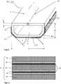
- FIG. 1shows a schematic cross section through an insulating glass unit according to the invention through the plane of the spacer frame.
- the insulating glass unit Ihas a first pane 11 and a second pane 12 (shown in FIG Figure 3 ).
- the spacer frame 10comprises four polymeric hollow profile spacers 13.1, 13.2, 13.3 and 13.4, which are each arranged along one of the four sides 14.1, 14.2, 14.3 and 14.4 of the insulating glass unit I.
- the four polymer hollow profile spacers 13.1, 13.2, 13.3 and 13.4are plugged together at the corners of the insulating glass unit by means of corner connectors 25.
- connection via plug connectorshas the advantage that different types of hollow profile spacers can easily be combined with one another in a spacer frame 10.
- corner connectors 25can be designed in such a way that one of the four hollow profile spacers is prevented from being filled with a desiccant 21 is that the desiccant 21 penetrates into the next hollow profile spacer.
- the insulating glass unit Iis rectangular and has two opposite first sides 14.1, 14.2 and two opposite second sides 14.3 and 14.4. Two first polymeric hollow profile spacers 13.1 and 13.2 are attached along the two first sides 14.1 and 14.2. Two second polymeric hollow profile spacers 13.3 and 13.4 are arranged along the two second sides.
- the first two polymeric hollow profile spacers 13.1 and 13.2are polymeric hollow profile spacers according to the prior art with a polymeric base body 1 consisting essentially of styrene acrylonitrile (SAN) with 35% glass fibers as reinforcing fibers. These reinforcing fibers increase the mechanical stability of the polymeric hollow profile spacer and have proven themselves as reinforcing fibers for polymeric spacers.
- the first polymer hollow profile spacers 13.1 and 13.2are provided on the outer wall with a gas- and vapor-tight barrier which seals the inner space between the panes.
- a multilayer filmcomprising three layers of polyethylene terephthalate (PET) with a thickness of 12 ⁇ m each and two aluminum layers with a thickness of 150 nm each is suitable.
- the aluminum layersare arranged alternately with the PET layers.
- openings 29are made, via which any moisture in the inner space between the panes 8 can be absorbed by the molecular sieve, which is filled as desiccant 21 in the cavities 5 of the first polymer hollow profile spacers 13.1 and 13.2.
- the second polymeric hollow profile spacers 13.3 and 13.4comprise a polymeric base body 1 which consists essentially of styrene acrylonitrile (SAN) and contains 0% reinforcing fibers.
- SANstyrene acrylonitrile
- the absence of the reinforcing fibersleads to hollow profile spacers 13.3 and 13.4, which have a lower mechanical stability than those with reinforcing fibers.
- the second polymer hollow profile spacers 13.3 and 13.4are transparent and do not contain any desiccant filling. The filling of the first two polymer hollow profile spacers 13.1 and 13.2 is sufficient to absorb the moisture from the inner space 8 between the panes.
- the second polymer hollow profile spacers 13.3 and 13.4contain a transparent barrier film 6.
- a transparent siliconeis attached as a transparent secondary sealant 28.1.
- the transparent silicone 28.1is arranged around the circumference so that there are no material incompatibilities between different secondary sealants. This embodiment is also easier to produce in terms of production than combining different secondary sealing means 28.
- the transparent silicone along the second sides 14.3 and 14.4 in combination with the transparent polymeric hollow profile spacers 13.3 and 13.4leads to an insulating glass unit I with two sides 14.3 and 14.4, along which an unobstructed view of the objects behind the insulating glass unit I is possible even in the edge area is.
- the insulating glass unit Ithus has a maximum transparent area. Only along the first sides 14.1 and 14.2 does an edge bond with the first polymer hollow profile spacers 13.1, 13.2 block the view through the edge region of the insulating glass unit I.
- FIG 2shows a door II according to the invention for a refrigerated shelf.
- the door IIcomprises two horizontal frame elements 30.1 and 30.2 and an insulating glass unit I, the structure of which in cross section in Figure 1 is shown schematically.
- the horizontal frame elements 30.1 and 30.2are arranged along the first sides 14.1 and 14.2 of the insulating glass unit I.
- the two horizontal frame elements 30.1 and 30.2hide the view of the first polymer hollow profile spacers 13.1 and 13.2 and the edge bond with primary and secondary sealing means.
- the corner connectors 25are also hidden by the edge bond.
- the horizontal frame elements 30.1 and 30.2are formed from a 0.3 mm thick stainless steel sheet.
- the frame elements 30.1 and 30.2increase the stability of the door II.
- the horizontal frame element 30.2is at the top when the door II is installed vertically in a refrigerated shelf or at the rear when the door II is installed horizontally.
- the horizontal stainless steel sheet 30.2surrounds the first and second disks 11 and 12 and thus protects the edges of the disks from damage.
- the horizontal frame element 30.1, which would be arranged at the bottom after installation in a refrigerated shelf or at the front when installed in a freezer,is constructed in exactly the same way as the upper or rear frame element 30.2.
- the horizontal frame elements 30.1 and 30.2are glued to the insulating glass unit I. Fastening means such as hinges can be attached to the horizontal frame elements 30.1 and 30.2 when installed in a refrigerated shelf or rails when used as a sliding door in a freezer.
- Figure 3shows a cross section of an insulating glass unit I according to the invention in the edge area.
- the structure of the insulating glass unit Iis basically the same along all four sides. Differences occur between the first and second polymeric hollow profile spacers.
- the pictureshows a hollow profile spacer filled with desiccant 21, which is only arranged along the first sides, as in FIG Figure 1 is shown. The description of the figure is generally not based on a particular polymeric hollow profile spacer.
- the first pane 11is connected to the first side wall 2.1 of the polymeric hollow profile spacer 13 via a transparent primary sealing means 27.1, and the second pane 12 is attached to the second side wall 2.2 via the transparent primary sealing means 27.1.
- the transparent primary sealant 27.1contains a transparent crosslinking polyisobutylene.
- the inner space 8 between the panesis located between the first pane 11 and the second pane 12 and is delimited by the glazing interior wall 3 of the spacer 13.
- the cavity 5is filled with a desiccant 21, for example molecular sieve.
- the cavity 5is connected to the inner space 8 between the panes via openings in the interior wall 29 of the glazing. A gas exchange takes place through the openings 29 between the cavity 5 and the inner space between the panes 8, the desiccant 21 absorbing the humidity from the inner space 8 between the panes.
- the first pane 11 and the second pane 12protrude beyond the side walls 2.1 and 2.2 so that an outer space 7 between the panes is created, which is located between the first pane 11 and the second pane 12 and is delimited by the outer wall of the hollow profile spacer 4.
- the outer space 7 between the panesis filled with a transparent secondary sealant 28.1.
- the transparent secondary sealant 28.1is, for example, a silicone. Silicones absorb the forces acting on the edge seal particularly well and thus contribute to the high stability of the insulating glass unit I.
- the first pane 11 and the second pane 12are made of soda-lime glass with a thickness of 3 mm each.
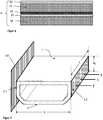
- FIG. 4shows a cross section of a polymeric hollow profile spacer 13.1, 13.2 suitable for an insulating glass unit I according to the invention.
- the polymeric hollow profile spacer 13comprises a polymeric base body with a first Side wall 2.1, a side wall 2.2 running parallel to it, a glazing interior wall 3 and an outer wall 4.
- the glazing interior wall 3runs perpendicular to the side walls 2.1 and 2.2 and connects the two side walls.
- the outer wall 4lies opposite the glazing interior wall 3 and connects the two side walls 2.1 and 2.2.
- the outer wall 4runs essentially perpendicular to the side walls 2.1 and 2.2.
- the sections of the outer wall 4.1 and 4.2 closest to the side walls 2.1 and 2.2are, however, inclined at an angle of approximately 45 ° to the outer wall 4 in the direction of the side walls 2.1 and 2.2.
- the angled geometryimproves the stability of the hollow profile spacer 13 and enables better bonding with a barrier film 6.
- the wall thickness d of the hollow profileis 1 mm.
- the hollow profile 1has, for example, a total height h G of 6.5 mm and a width b of 16 mm.
- the outer wall 4, the glazing interior wall 3 and the two side walls 2.1 and 2.2enclose the cavity 5.
- the cavity 5can accommodate a desiccant 21.
- the polymeric base body 1contains styrene-acrylic-nitryl (SAN) and, in the case of the first polymeric hollow profile spacer, additionally about 35% by weight of glass fiber.
- a gas- and vapor-tight barrier film 6, which improves the tightness of the spacer 13,is attached to the outer wall 4 and approximately half of the side walls 2.1 and 2.2.
- the barrier film 6can be attached to the polymeric base body 1 with a polyurethane hotmelt adhesive, for example.
- a barrier coating 9can also be applied. This can be applied directly to the polymer base, for example in a vacuum coating process.
- FIG. 5shows a cross section through a transparent barrier film 6, which is suitable to be attached to a transparent first polymeric hollow profile spacer 13.1, 13.2.
- the transparent barrier film 6is a multilayer film made of polymeric layers 19 and ceramic layers 20.
- the polymeric layersconsist essentially of 12 ⁇ m thick polyethylene films and the ceramic layers of a 40 nm thick SiO x layer.
- Two polymer layers 19are arranged alternately with two ceramic layers 20. The alternating arrangement has the advantage that defects in one of the ceramic layers 20 can be compensated for by the other layers.
- a total of three ceramic layers 20 and three polymer layers 19are part of the barrier film.
- Two of the ceramic layers 20are connected directly via an adhesive layer 18, for example a 3 ⁇ m thick layer of polyurethane adhesive. Through this arrangement all ceramic layers 20 protected by polymer layers 19 against mechanical damage from the outside.
- the transparent barrier film 6 showncan be produced particularly easily by connecting three polyethylene films, each coated with an SiO x layer, via two adhesive layers 18.
- FIG. 6shows a cross section through a further embodiment of a transparent barrier film 6, which is suitable to be attached to a transparent first polymeric hollow profile spacer 13.1, 13.2.
- the transparent barrier film 6is a multilayer film with two polymer layers 19, which essentially consist of polyethylene terephthalate (PET), and two ceramic layers 20, each of which consists of 30 nm thick silicon oxide (SiO x ) layers.
- PETpolyethylene terephthalate
- SiO xsilicon oxide
- the production of the barrier film 6can advantageously take place by gluing two PET films coated with SiO x.
- the adhesive layer 18is, for example, a 3 ⁇ m thick polyurethane adhesive layer.
- Such a barrier film 6 with an external ceramic layer 20is preferably glued to the hollow profile spacer in such a way that the polymeric layer 19 faces the hollow profile spacer and the ceramic layer 20 faces the external environment or the secondary sealant.
- the ceramic layercan serve as an adhesion promoter, since the adhesion of the usual secondary sealants to a ceramic layer is improved compared to the adhesion to a polymer layer.
- Figure 7shows a perspective cross-section of a polymer base body 1 and the essential parameters for measuring the compressive strength of a polymer hollow profile spacer.
- the height of the side wall h S , the length L of a piece of the hollow profile spacer and the direction of the force F, which acts when measuring the compressive strength,are also shown.
- the compressive strengthdescribes the stability of the polymeric hollow profile spacer in the transverse direction.
- a polymeric base body 1is arranged with the first side wall 2.1 on a non-movable contact surface 40. This can be in the orientation as in Figure 6 shown, or the polymer base body 1 can be placed with the first side wall 2.1 on the pressing surface 40 so that the in Figure 6 The arrangement shown is rotated 90 ° counterclockwise.
- a piece of polymeric base body 1 of length Lis selected for the measurement.
- the sections 4.1 and 4.1 of the outer wall 4 closest to the side wallsare angled. Accordingly, the area with which the polymeric base body 1 with the The contact surface 40 is in contact, defined by the length L and the height h S of a side wall 2.
- the area L xh S on the second side wall 2.2is characterized by a fine checkered pattern.
- a door according to the inventionis equipped with four polymer hollow profile spacers, as in FIG Figures 1 and 2 shown.
- the dooris rectangular and the first and second panes are each 80 cm x 180 cm.
- a transparent butylwas used as the primary sealant and a transparent silicone was used as the secondary sealant.
- the first two polymeric hollow profile spacersare filled with molecular sieve, while the second polymeric hollow profile spacers do not contain any desiccant.
- the inner space between the paneswas filled with an inert gas, in this case argon.
- the polymer base bodies of the first polymer hollow profile spacersessentially consist of styrene-acrylic-nitrile (SAN) with a glass fiber content of around 35%.
- the polymer base bodies of the second polymer hollow profile spacersessentially consist of styrene-acrylic-nitrile (SAN) and have a proportion of reinforcing fibers of 0%.
- the compressive strength F max / L of the second polymer hollow profile spacersis accordingly about 28% lower than that of the first polymer hollow profile spacers.
- the influence of the barrier layer or barrier film applied to the base body on the compressive strength valuescan be neglected.
- the compressive strengths of all polymer hollow profile spacersare as high as those of the first polymer hollow profile spacers in the example.
- Both doorswere built into a refrigerated shelf with an inside temperature of - 18 ° C and an outside temperature of 20 ° C.
- the doorswere automatically opened and closed again 10,000 times on a test bench. After closing, the doors were kept closed for at least 90 seconds so that the temperature in the interior of the refrigerated shelf did not become too hot during the test.
- the insulating glass units of the example door and the comparative example doorwere examined. The external appearance of both doors was unscathed. The edge seal was intact and the panes were not fogged up from the inner space between the panes.
- a dew point determinationwas carried out as described in DIN EN 1279.
Landscapes
- Engineering & Computer Science (AREA)
- Civil Engineering (AREA)
- Structural Engineering (AREA)
- Physics & Mathematics (AREA)
- Thermal Sciences (AREA)
- Joining Of Glass To Other Materials (AREA)
- Securing Of Glass Panes Or The Like (AREA)
- Freezers Or Refrigerated Showcases (AREA)
- Refrigerator Housings (AREA)
- Laminated Bodies (AREA)
Description
Translated fromGermanDie Erfindung betrifft eine Isolierglaseinheit für ein Kühlmöbel, eine Tür für ein Kühlmöbel, ein Verfahren zur Herstellung einer solchen Isolierglaseinheit und deren Verwendung.The invention relates to an insulating glass unit for a refrigerated cabinet, a door for a refrigerated cabinet, a method for producing such an insulating glass unit and its use.
Kühlregale oder Kühlschränke mit transparenten Türen sind weit verbreitet, um gekühlte Waren für Kunden auszustellen und zu präsentieren. Dabei werden die Waren bei Temperaturen unter 10 °C im Kühlregal gehalten und so vor dem schnellen Verderben geschützt. Um den Wärmeverlust so gering wie möglich zu halten, werden häufig Isolierglaseinheiten als Türen eingesetzt. Transparente Türen ermöglichen ein Betrachten der Ware ohne die Schränke oder Regale öffnen zu müssen. Jedes Öffnen der Türen führt zu einer Erhöhung der Temperatur im Kühlregal und setzt damit die Waren der Gefahr der Erwärmung aus. Es ist daher gewünscht, die Waren so zu präsentieren, dass die Zahl der Öffnungsvorgänge minimiert wird. Dazu ist es wichtig, dass die Sicht durch die geschlossenen Türen möglichst wenig eingeschränkt wird. Bei herkömmlichen Isolierglaseinheiten wird die Sicht zumindest im Randbereich durch Elemente des nichttransparenten umlaufenden Türrahmens behindert. Der Türrahmen verdeckt bei herkömmlichen Isolierglaseinheiten den ebenfalls nichttransparenten umlaufenden Randverbund. Der Randverbund einer Isolierglaseinheit umfasst in der Regel mindestens einen umlaufenden Abstandhalter, feuchtigkeitsbindendes Trockenmittel sowie ein primäres Dichtmittel zur Befestigung des Abstandhalters zwischen den Scheiben und ein sekundäres Dichtmittel, das den Randverbund stabilisiert und zusätzlich abdichtet. Diese Komponenten sind üblicherweise nicht transparent, das heißt im Bereich des umlaufenden Randverbunds ist die Sicht eingeschränkt.Cooling shelves or refrigerators with transparent doors are widely used to display and present refrigerated goods to customers. The goods are kept in the refrigerated shelf at temperatures below 10 ° C and thus protected from spoilage. In order to keep the heat loss as low as possible, insulating glass units are often used as doors. Transparent doors make it possible to look at the goods without having to open the cupboards or shelves. Each time the doors are opened, the temperature in the refrigerated shelf increases and the goods are exposed to the risk of heating up. It is therefore desirable to present the goods in such a way that the number of opening processes is minimized. For this it is important that the view through the closed doors is restricted as little as possible. In conventional insulating glass units, the view is obstructed, at least in the edge area, by elements of the non-transparent surrounding door frame. With conventional insulating glass units, the door frame conceals the likewise non-transparent all-round edge bond. The edge bond of an insulating glass unit usually comprises at least one circumferential spacer, moisture-binding desiccant and a primary sealant for fastening the spacer between the panes and a secondary sealant that stabilizes and additionally seals the edge bond. These components are usually not transparent, which means that the view is restricted in the area of the surrounding edge seal.
Zur Lösung dieses Problems sind verschiedene Ansätze bekannt. Aus der
Ein weiterer Lösungsansatz ist in der
Aus der internationalen Patentanmeldung
Aus dem deutschen Patent
Die Aufgabe der vorliegenden Erfindung ist es, eine verbesserte Isolierglaseinheit für ein Kühlmöbel bereitzustellen, eine Tür für ein Kühlmöbel bereitzustellen, und außerdem ein vereinfachtes Verfahren zur Herstellung einer Isolierglaseinheit bereitzustellen. Speziell war es die Aufgabe der vorliegenden Erfindung, eine Isolierglaseinheit für ein Kühlmöbel bereitzustellen, das einerseits eine besonders hohe Stabilität und Druckfestigkeit der Abstandshalter aufweist und andererseits die Gestaltungsmöglichkeiten der Abstandshalter vervielfältigt.The object of the present invention is to provide an improved insulating glass unit for a refrigerated cabinet, to provide a door for a refrigerated cabinet, and also to provide a simplified method for producing an insulating glass unit. In particular, it was the object of the present invention to provide an insulating glass unit for a refrigerated cabinet which, on the one hand, has a particularly high stability and compressive strength of the spacers and, on the other hand, multiplies the design possibilities of the spacers.
Die Aufgabe der vorliegenden Erfindung wird erfindungsgemäß durch eine Isolierglaseinheit nach dem unabhängigen Anspruch 1 gelöst. Bevorzugte Ausführungen der Erfindung gehen aus den Unteransprüchen hervor.The object of the present invention is achieved according to the invention by an insulating glass unit according to
Die erfindungsgemäße Isolierglaseinheit für ein Kühlmöbel umfasst mindestens eine erste Scheibe, eine davon beabstandete zweite Scheibe und einen umlaufenden Abstandhalterrahmen zwischen der ersten Scheibe und der zweiten Scheibe. Ein innerer Scheibenzwischenraum wird begrenzt durch den Abstandhalterrahmen, die erste Scheibe und die zweite Scheibe. Der innere Scheibenzwischenraum wird vom Abstandhalterrahmen eingeschlossen. Die Isolierglaseinheit hat vier Seiten. Die Seiten der Isolierglaseinheit sind die Seiten, entlang denen sich der Randbereich der Isolierglaseinheit befindet. Die beiden ersten Seiten liegen einander gegenüber und die beiden zweiten Seiten liegen einander gegenüber. Der Abstandhalterrahmen umfasst mindestens vier polymere Hohlprofilabstandhalter. Jeder polymere Hohlprofilabstandhalter ist entlang einer der vier Seiten der Isolierglaseinheit befestigt. Die polymeren Hohlprofilabstandhalter sind jeweils entlang der vier Seiten zwischen der ersten Scheibe und der zweiten Scheibe über ein primäres Dichtmittel befestigt. Zwei erste polymere Hohlprofilabstandhalter sind entlang der zwei gegenüberliegenden ersten Seiten angeordnet und zwei zweite polymere Hohlprofilabstandhalter sind entlang der zwei zweiten Seiten der Isolierglaseinheit angeordnet. Die ersten polymeren Hohlprofilabstandhalter enthalten 5% bis 50% Verstärkungsfasern. Die Verstärkungsfasern führen zu einer erhöhten Stabilität der polymeren Hohlprofilabstandhalter und damit zu einer längeren Lebensdauer der Isolierglaseinheit. Gleichzeitig weisen die polymeren Hohlprofilabstandhalter im Vergleich zu metallischen Hohlprofilabstandhaltern vorteilhaft niedrige Wärmeleitfähigkeiten auf. Die zweiten polymeren Hohlprofilabstandhalter enthalten 0 % bis 0,5 % Verstärkungsfasern, wodurch die Gestaltungsmöglichkeiten besonders vielfältig sind. Die Tatsache, dass keine bzw. nahezu keine Verstärkungsfasern enthalten sind, ermöglicht zum Beispiel die Herstellung von transparenten Abstandhaltern oder von Abstandhaltern mit farbigen Mustern, die ansonsten von der Anwesenheit der Verstärkungsfasern gestört werden würden. Aufgrund der fehlenden Verstärkung weisen die zweiten polymeren Hohlprofilabstandhalter eine geringere Druckfestigkeit auf. Überraschend weist jedoch die erfindungsgemäße Isolierglaseinheit mit ersten und zweiten polymeren Hohlprofilabstandhaltern eine ausgezeichnete Stabilität auf. Die erfindungsgemäße Anordnung entlang gegenüberliegender Seiten der Isolierglaseinheit resultiert in einer hochstabilen Isolierglaseinheit, die vergleichbar ist mit Isolierglaseinheiten, die entlang aller vier Seiten verstärkte Abstandhalter aufweisen. Im Vergleich zu Isolierglaseinheiten mit sowohl metallischen als auch polymeren Abstandhaltern hat die erfindungsgemäße Isolierglaseinheit den Vorteil, dass der Randverbund eine geringere Wärmeleitfähigkeit aufweist. Außerdem gibt es durch die unterschiedlichen Wärmeausdehnungskoeffizienten der metallischen und polymeren Abstandhalter einen erhöhten Spannungsaufbau im Abstandhalterrahmen, der zu einem frühzeitigen Ablösen der Dichtmittel im Randbereich führen kann. Somit stellt die Erfindung eine stabile Isolierglaseinheit bereit, die entlang aller vier Seiten ein polymeres Abstandhalterprofil aufweist und somit ausgezeichnete wärmeisolierende Eigenschaften hat.The insulating glass unit according to the invention for a refrigerated cabinet comprises at least a first pane, a second pane spaced therefrom and a circumferential spacer frame between the first pane and the second pane. An inner space between the panes is delimited by the spacer frame, the first pane and the second pane. The inner space between the panes is enclosed by the spacer frame. The insulating glass unit has four sides. The sides of the insulating glass unit are the sides along which the edge area of the insulating glass unit is located. The two first sides are opposite each other and the two second sides are opposite each other. The spacer frame comprises at least four polymeric hollow profile spacers. Each hollow polymer profile spacer is attached along one of the four sides of the insulating glass unit. The polymeric hollow profile spacers are each along the four sides between the first washer and the second washer are secured by a primary sealant. Two first polymeric hollow profile spacers are arranged along the two opposite first sides and two second polymeric hollow profile spacers are arranged along the two second sides of the insulating glass unit. The first polymer hollow profile spacers contain 5% to 50% reinforcement fibers. The reinforcing fibers lead to an increased stability of the polymer hollow profile spacers and thus to a longer service life of the insulating glass unit. At the same time, the polymer hollow profile spacers have advantageously low thermal conductivities compared to metallic hollow profile spacers. The second polymer hollow profile spacers contain 0% to 0.5% reinforcing fibers, which means that the design options are particularly diverse. The fact that no or almost no reinforcing fibers are contained enables, for example, the production of transparent spacers or spacers with colored patterns, which would otherwise be disturbed by the presence of the reinforcing fibers. Due to the lack of reinforcement, the second polymeric hollow profile spacers have a lower compressive strength. Surprisingly, however, the insulating glass unit according to the invention with first and second polymeric hollow profile spacers has excellent stability. The arrangement according to the invention along opposite sides of the insulating glass unit results in a highly stable insulating glass unit which is comparable to insulating glass units which have reinforced spacers along all four sides. Compared to insulating glass units with both metallic and polymeric spacers, the insulating glass unit according to the invention has the advantage that the edge bond has a lower thermal conductivity. In addition, due to the different coefficients of thermal expansion of the metallic and polymer spacers, there is an increased build-up of stress in the spacer frame, which can lead to premature detachment of the sealant in the edge area. The invention thus provides a stable insulating glass unit which has a polymeric spacer profile along all four sides and thus has excellent heat-insulating properties.
In einer bevorzugten Ausführungsform der erfindungsgemäßen Isolierglaseinheit sind die zweiten polymeren Hohlprofilabstandhalter transparent ausgeführt. Dies hat den Vorteil, dass entlang von zwei gegenüberliegenden Seiten keine Sichtbarriere vorhanden ist, sodass die Durchsichtfläche maximiert wird. Da die zweiten polymeren Hohlprofilabstandhalter erfindungsgemäß praktisch keine Verstärkungsfasern enthalten, können diese transparent durchscheinend gestaltet werden. Bei herkömmlichen Isolierglaseinheiten sind für polymere Hohlprofilabstandhalter in der Regel rundum Verstärkungsfasern vorgesehen. Daher werden bisher keine Isolierglaseinheiten mit transparenten Hohlprofilabstandhaltern eingesetzt. Die erfindungsgemäße Isolierglaseinheit ist auch ohne die stabilisierende Wirkung der Verstärkungsfasern entlang aller vier Seiten überraschend stabil, sodass die transparente Ausführung möglich wird.In a preferred embodiment of the insulating glass unit according to the invention, the second polymeric hollow profile spacers are transparent. This has the advantage that there is no visual barrier along two opposite sides, so that the transparent area is maximized. As the second polymer According to the invention, hollow profile spacers contain practically no reinforcing fibers, they can be designed to be transparent. In conventional insulating glass units, reinforcement fibers are generally provided all around for polymeric hollow profile spacers. For this reason, no insulating glass units with transparent hollow profile spacers have been used so far. The insulating glass unit according to the invention is surprisingly stable along all four sides even without the stabilizing effect of the reinforcing fibers, so that the transparent design is possible.
Transparent im Sinne der Erfindung bedeutet, dass das Material durchsichtig ist. Ein Betrachter kann die hinter der Materialschicht angeordneten Gegenstände erkennen. Das Material ist demnach lichtdurchlässig und weist bevorzugt eine Lichttransmission im sichtbaren Spektrum von mindestens 30% auf, besonders bevorzugt von mindestens 50%.Transparent in the context of the invention means that the material is transparent. A viewer can recognize the objects arranged behind the material layer. The material is accordingly translucent and preferably has a light transmission in the visible spectrum of at least 30%, particularly preferably of at least 50%.
Verstärkungsfasern im Sinne der Erfindung bezeichnen Fasern, die zur Verstärkung des Profils dem polymeren Grundkörper des Hohlprofils hinzugefügt werden. Diese Fasern sind bevorzugt Glasfasern, Naturfasern oder Keramikfasern. Diese Fasern erhöhen die Steifigkeit und die Festigkeit des Profils. Bevorzugt werden die Fasern in Form von Kurzfasern eingesetzt mit Längen zwischen 0,05 mm und 0,5 mm. Diese Längen können besonders gut in einem Extruder verarbeitet werden, sodass die Verstärkungsfasern direkt bei der Extrusion eingearbeitet werden können. Die Prozentangaben sind Massenprozent Verstärkungsfasern bezogen auf den Anteil der Verstärkungsfasern am polymeren Grundkörper, das heißt eventuelle Barrierefolien oder Beschichtungen werden nicht berücksichtigt.Reinforcing fibers in the context of the invention denote fibers which are added to the polymeric base body of the hollow profile to reinforce the profile. These fibers are preferably glass fibers, natural fibers or ceramic fibers. These fibers increase the rigidity and strength of the profile. The fibers are preferably used in the form of short fibers with lengths between 0.05 mm and 0.5 mm. These lengths can be processed particularly well in an extruder, so that the reinforcing fibers can be incorporated directly during the extrusion. The percentages are percentages by mass of reinforcing fibers based on the proportion of reinforcing fibers in the polymer base body, i.e. any barrier films or coatings are not taken into account.
In einer bevorzugten Ausführungsform der erfindungsgemäßen Isolierglaseinheit umfassen die polymeren Hohlprofilabstandhalter mindestens einen polymeren Grundkörper mindestens umfassend eine erste Seitenwand, eine parallel dazu angeordnete zweite Seitenwand, eine Verglasungsinnenraumwand, eine Außenwand und einen Hohlraum. Der Hohlraum wird von den Seitenwänden, der Verglasungsinnenraumwand und der Außenwand umschlossen. Die Verglasungsinnenraumwand ist dabei senkrecht zu den Seitenwänden angeordnet und verbindet die erste Seitenwand mit der zweiten Seitenwand. Die Seitenwände sind die Wände des polymeren Hohlprofilabstandhalters, an denen die äußeren Scheiben der Isolierglaseinheit angebracht werden. Die erste Seitenwand und die zweite Seitenwand verlaufen parallel zueinander. Die Verglasungsinnenraumwand ist die Wand des polymeren Hohlprofilabstandhalters, die in der fertigen Isolierglaseinheit zum inneren Scheibenzwischenraum weist. Die Außenwand ist im Wesentlichen parallel zur Verglasungsinnenraumwand angeordnet und verbindet die erste Seitenwand mit der zweiten Seitenwand. Die Außenwand weist zum äußeren Scheibenzwischenraum. Der Hohlraum des polymeren Grundkörpers führt zu einer Gewichtsreduktion im Vergleich zu einem massiv ausgeformten Abstandhalter und kann ganz oder teilweise mit einem Trockenmittel gefüllt sein.In a preferred embodiment of the insulating glass unit according to the invention, the polymeric hollow profile spacers comprise at least one polymeric base body at least comprising a first side wall, a second side wall arranged parallel thereto, a glazing interior wall, an exterior wall and a cavity. The cavity is enclosed by the side walls, the interior glazing wall and the exterior wall. The glazing interior wall is arranged perpendicular to the side walls and connects the first side wall to the second side wall. The side walls are the walls of the polymeric hollow profile spacer to which the outer panes of the insulating glass unit are attached. The first side wall and the second side wall run parallel to each other. The interior wall of the glazing is the wall of the polymer hollow profile spacer that faces the inner space between the panes in the finished insulating glass unit. The outer wall is arranged essentially parallel to the glazing interior wall and connects the first side wall to the second side wall. The outer wall faces the outer space between the panes. The cavity of the polymer base body leads to a weight reduction compared to a solidly shaped spacer and can be completely or partially filled with a desiccant.
Bevorzugt enthält mindestens einer der beiden ersten polymeren Hohlprofilabstandhalter ein Trockenmittel und der Hohlraum der beiden zweiten polymeren Hohlprofilabstandhalter ist frei von Trockenmittel. Das Trockenmittel bindet Feuchtigkeit, die im inneren Scheibenzwischenraum vorhanden ist und verhindert so ein Beschlagen der Isolierglaseinheit von innen. Die zweiten polymeren Hohlprofilabstandhalter müssen nicht mit Trockenmittel gefüllt werden, da die Anbringung in mindestens einem der Hohlprofilabstandhalter ausreichend ist, um ein Beschlagen der Scheiben zu verhindern. So kann einerseits Material gespart werden und andererseits hat dieses Vorgehen auch optische Vorteile.Preferably, at least one of the two first polymeric hollow profile spacers contains a desiccant and the cavity of the two second polymeric hollow profile spacers is free of desiccant. The desiccant binds moisture that is present in the space between the panes and thus prevents the insulating glass unit from fogging up from the inside. The second polymer hollow profile spacers do not have to be filled with desiccant, since the attachment in at least one of the hollow profile spacers is sufficient to prevent the panes from fogging up. On the one hand, this saves material and, on the other hand, this procedure also has optical advantages.
Das Trockenmittel enthält bevorzugt Kieselgele, Molekularsiebe, CaCl2, Na2SO4, Aktivkohle, Silikate, Bentonite, Zeolithe und/oder Gemische davon.The desiccant preferably contains silica gels, molecular sieves, CaCl2 , Na2 SO4 , activated carbon, silicates, bentonites, zeolites and / or mixtures thereof.
Die Außenwand des polymeren Grundkörpers ist die der Verglasungsinnenraumwand gegenüberliegende Wand, die vom inneren Scheibenzwischenraum weg in Richtung des äußeren Scheibenzwischenraums weist. Die Außenwand verläuft bevorzugt senkrecht zu den Seitenwänden. Die den Seitenwänden nächstliegenden Abschnitte der Außenwand können jedoch alternativ in einem Winkel von bevorzugt 30° bis 60° zur Außenwand in Richtung der Seitenwände geneigt sein. Diese abgewinkelte Geometrie verbessert die Stabilität des polymeren Hohlprofilabstandhalters und ermöglicht eine bessere Verklebung des Grundkörpers mit einer Barrierefolie. Eine plane Außenwand, die sich in ihrem gesamten Verlauf senkrecht zu den Seitenwänden (parallel zur Verglasungsinnenraumwand) verhält, hat hingegen den Vorteil, dass die Dichtfläche zwischen polymerem Hohlprofilabstandhalter und Seitenwänden maximiert wird und eine einfachere Formgebung den Produktionsprozess erleichtert.The outer wall of the polymer base body is the wall opposite the glazing interior wall, which points away from the inner space between the panes in the direction of the outer space between the panes. The outer wall preferably runs perpendicular to the side walls. The sections of the outer wall closest to the side walls can, however, alternatively be inclined at an angle of preferably 30 ° to 60 ° to the outer wall in the direction of the side walls. This angled geometry improves the stability of the polymeric hollow profile spacer and enables better bonding of the base body to a barrier film. A flat outer wall, which is perpendicular to the side walls (parallel to the glazing interior wall) in its entire course, has the advantage that the sealing surface between the polymer hollow profile spacer and the side walls is maximized and a simpler shape facilitates the production process.
Bevorzugt wird der polymere Grundkörper des polymeren Hohlprofilabstandhalters aus Polymeren gefertigt, da diese eine geringe Wärmeleitfähigkeit besitzen, was zu verbesserten wärmedämmenden Eigenschaften des Randverbunds führt. Besonders bevorzugt enthält der polymere Grundkörper Biokomposite, Polyethylen (PE), Polycarbonate (PC), Polypropylen (PP), Polystyrol, Polybutadien, Polynitrile, Polyester, Polyurethane, Polymethylmetacrylate, Polyacrylate, Polyamide, Polyethylenterephthalat (PET), Polybutylenterephthalat (PBT), Polyvinylchlorid (PVC), besonders bevorzugt Acrylnitril-Butadien-Styrol (ABS), Acrylester-Styrol-Acrylnitril (ASA), Acrylnitril-Butadien-Styrol/Polycarbonat (ABS/PC), Styrol-Acrylnitril (SAN), PET/PC, PBT/PC und/oder Copolymere oder Gemische davon.The polymeric base body of the polymeric hollow profile spacer is preferably made from polymers, since these have a low thermal conductivity, which leads to improved heat-insulating properties of the edge seal. The polymer base body particularly preferably contains biocomposites, polyethylene (PE), polycarbonates (PC), polypropylene (PP), polystyrene, polybutadiene, polynitriles, polyesters, polyurethanes, polymethyl methacrylates, polyacrylates, polyamides, polyethylene terephthalate (PET), polybutylene terephthalate (PBT), polyvinyl chloride (PVC), particularly preferred acrylonitrile-butadiene-styrene (ABS), acrylic ester-styrene-acrylonitrile (ASA), acrylonitrile-butadiene-styrene / polycarbonate (ABS / PC), styrene-acrylonitrile (SAN), PET / PC, PBT / PC and / or copolymers or mixtures thereof.
In einer bevorzugten Ausführungsform der erfindungsgemäßen Isolierglaseinheit enthalten die ersten polymeren Hohlprofilabstandhalter als Verstärkungsfasern 15 % bis 40 % Glasfasern, bezogen auf den polymeren Grundkörper. Besonders bevorzugt enthalten die ersten polymeren Hohlprofilabstandhalter 20 % bis 35 % Glasfasern. In diesem Bereich wird mit Glasfasern eine besonders gute Stabilisierung der polymeren Hohlprofilabstandhalter erzielt und gleichzeitig eine niedrige Wärmeleitfähigkeit des Hohlprofilabstandhalters erreicht. Durch die Wahl des Glasfaseranteils im Hohlprofil kann der Wärmeausdehnungskoeffizient des Hohlprofils variiert und angepasst werden. So können Spannungen zwischen den unterschiedlichen Materialien der ersten und zweiten polymeren Hohlprofilabstandhaltern vermieden werden. Glasfasern lassen sich besonders gut verarbeiten und insbesondere gut zusammen mit dem Material des polymeren Grundkörpers zusammen extrudieren.In a preferred embodiment of the insulating glass unit according to the invention, the first polymeric hollow profile spacers contain 15% to 40% glass fibers as reinforcing fibers, based on the polymeric base body. The first polymeric hollow profile spacers particularly preferably contain 20% to 35% glass fibers. In this area a particularly good stabilization of the polymeric hollow profile spacers is achieved with glass fibers and at the same time a low thermal conductivity of the hollow profile spacer is achieved. By choosing the proportion of glass fiber in the hollow profile, the coefficient of thermal expansion of the hollow profile can be varied and adapted. In this way, stresses between the different materials of the first and second polymer hollow profile spacers can be avoided. Glass fibers can be processed particularly well and, in particular, can be extruded together well together with the material of the polymer base body.
Der polymere Hohlprofilabstandhalter weist bevorzugt entlang der Verglasungsinnenraumwand eine Breite von 5 mm bis 45 mm, bevorzugt von 10 mm bis 24 mm auf. Die Breite ist im Sinne der Erfindung die sich zwischen den Seitenwänden erstreckende Dimension. Die Breite ist der Abstand zwischen den voneinander abgewandten Flächen der beiden Seitenwände. Durch die Wahl der Breite der Verglasungsinnenraumwand wird der Abstand zwischen den Scheiben der Isolierglaseinheit bestimmt. Das genaue Abmaß der Verglasungsinnenraumwand richtet sich nach den Dimensionen der Isolierglaseinheit und der gewünschten Scheibenzwischenraumgröße.The polymeric hollow profile spacer preferably has a width of 5 mm to 45 mm, preferably 10 mm to 24 mm, along the interior wall of the glazing. For the purposes of the invention, the width is the dimension extending between the side walls. The width is the distance between the surfaces of the two side walls facing away from one another. The distance between the panes of the insulating glass unit is determined by the choice of the width of the glazing interior wall. The exact dimensions of the glazing interior wall depend on the dimensions of the insulating glass unit and the desired size of the space between the panes.
Der polymere Hohlprofilabstandhalter weist bevorzugt entlang der Seitenwände eine Höhe hG von 5 mm bis 15 mm, besonders bevorzugt von 6 mm bis 10 mm, auf. In diesem Bereich für die Höhe besitzt der Hohlprofilabstandhalter eine vorteilhafte Stabilität, ist aber andererseits in der Isolierglaseinheit vorteilhaft unauffällig. Außerdem weist der Hohlraum des Hohlprofilabstandhalters eine vorteilhafte Größe zur möglichen Aufnahme einer geeigneten Menge an Trockenmittel auf. Die Gesamthöhe hG ist der Abstand zwischen den voneinander abgewandten Flächen der Außenwand und der Verglasungsinnenraumwand.The polymer hollow profile spacer preferably has a height hG of 5 mm to 15 mm, particularly preferably 6 mm to 10 mm, along the side walls. In In this area for the height, the hollow profile spacer has an advantageous stability, but on the other hand is advantageously inconspicuous in the insulating glass unit. In addition, the cavity of the hollow profile spacer has an advantageous size for the possible accommodation of a suitable amount of desiccant. The total height hG is the distance between the surfaces of the outer wall facing away from one another and the interior wall of the glazing.
Die Wandstärke d des polymeren Hohlprofilabstandhalters beträgt 0,5 mm bis 15 mm, bevorzugt 0,5 mm bis 10 mm, besonders bevorzugt 0,7 mm bis 1,2 mm.The wall thickness d of the polymeric hollow profile spacer is 0.5 mm to 15 mm, preferably 0.5 mm to 10 mm, particularly preferably 0.7 mm to 1.2 mm.
In einer bevorzugten Ausführungsform der erfindungsgemäßen Isolierglaseinheit ist die Druckfestigkeit der zweiten polymeren Hohlprofilabstandhalter um 20 % bis 40 % niedriger als die der ersten polymeren Hohlprofilabstandhalter. Bei diesem Unterschied in der Druckfestigkeit werden besonders stabile Isolierglaseinheiten erhalten und gleichzeitig die Flexibilität in der Gestaltung der polymeren Hohlprofilabstandhalter erhöht.In a preferred embodiment of the insulating glass unit according to the invention, the compressive strength of the second polymeric hollow profile spacers is 20% to 40% lower than that of the first polymeric hollow profile spacers. With this difference in compressive strength, particularly stable insulating glass units are obtained and at the same time the flexibility in the design of the polymeric hollow profile spacers is increased.
Die Druckfestigkeit eines polymeren Hohlprofilabstandhalters im Sinne der Erfindung bezeichnet die Druckfestigkeit in Querrichtung des Hohlprofilabstandhalters. Die Querrichtung ist senkrecht zur Erstreckungsrichtung des Hohlprofils in der Ebene der Verglasungsinnenraumfläche des Hohlprofilabstandhalters. Der Abstand zwischen der ersten Scheibe und der zweiten Scheibe wird durch die Breite b des Hohlprofilabstandhalters in Querrichtung bestimmt. Die Druckfestigkeit beschreibt die Stabilität eines Abstandhalters, auf den durch die erste und zweite Scheibe in einer Isolierglaseinheit Druck ausgeübt wird. Die Druckfestigkeit wird in Kraft / Länge [N/cm] angegeben. Die Länge L wird in Erstreckungsrichtung des Hohlprofilabstandhalters gemessen und gibt an, wie lang das Stück Hohlprofilabstandhalter ist, auf das die Kraft seitlich einwirkt. Eine exemplarische Messung wird zusammen mit dem Beispiel beschrieben.The compressive strength of a polymer hollow profile spacer in the context of the invention denotes the compressive strength in the transverse direction of the hollow profile spacer. The transverse direction is perpendicular to the direction of extension of the hollow profile in the plane of the glazing interior surface of the hollow profile spacer. The distance between the first disk and the second disk is determined by the width b of the hollow profile spacer in the transverse direction. The compressive strength describes the stability of a spacer on which pressure is exerted by the first and second panes in an insulating glass unit. The compressive strength is given in force / length [N / cm]. The length L is measured in the direction of extent of the hollow profile spacer and indicates how long the piece of hollow profile spacer is on which the force acts laterally. An exemplary measurement is described together with the example.
Bei einem polymeren Hohlprofilabstandhalter mit einer Breite b von 12 mm - 20 mm, einer Wandstärke d von 1 mm und einer Gesamthöhe hG von 5 mm - 8 mm haben die ersten polymeren Hohlprofilabstandhalter bevorzugt eine Druckfestigkeit von 350 N/cm bis 450 N/cm. Die Druckfestigkeit der zweiten polymeren Hohlprofilabstandhalter ist bevorzugt um 50 N/cm bis 150 N/cm kleiner als die der ersten polymeren Hohlprofilabstandhalter, besonders bevorzugt um 100 N/cm kleiner. In diesen Bereichen wird eine besonders stabile Isolierglaseinheit erhalten.In the case of a polymer hollow profile spacer with a width b of 12 mm - 20 mm, a wall thickness d of 1 mm and a total height hG of 5 mm - 8 mm, the first polymer hollow profile spacers preferably have a compressive strength of 350 N / cm to 450 N / cm . The compressive strength of the second polymeric hollow profile spacer is preferably 50 N / cm to 150 N / cm less than that of the first polymer Hollow profile spacer, particularly preferably 100 N / cm smaller. A particularly stable insulating glass unit is obtained in these areas.
In einer bevorzugten Ausführungsform der erfindungsgemäßen Isolierglaseinheit sind die ersten polymeren Hohlprofilabstandhalter und die zweiten polymeren Hohlprofilabstandhalter über ein transparentes primäres Dichtmittel an der ersten Scheibe und der zweiten Scheibe befestigt. Die polymeren Hohlprofilabstandhalter sind so angeordnet, dass zwischen der ersten Scheibe und der zweiten Scheibe ein äußerer Scheibenzwischenraum entsteht, begrenzt durch die zur Umgebung weisende Außenwand des Hohlprofilabstandhalters. Die Scheiben ragen demnach etwas über den Hohlprofilabstandhalter hinaus, sodass der äußere Scheibenzwischenraum entsteht. Der äußere Scheibenzwischenraum ist mit einem transparenten sekundären Dichtmittel verfüllt. Der äußere Scheibenzwischenraum der Isolierglaseinheit wird begrenzt von den beiden Scheiben und der Außenwand des Hohlprofilabstandhalters. Das sekundäre Dichtmittel dient der Stabilisierung des Randverbunds der Isolierglaseinheit und nimmt die auf den Randverbund wirkenden mechanischen Kräfte auf. Das primäre Dichtmittel dient der Befestigung der Scheiben und der Abdichtung des inneren Scheibenzwischenraums gegen das Eindringen von Feuchtigkeit und den Verlust einer eventuell vorhandenen Gasfüllung. Die Befestigung aller polymeren Hohlprofilabstandhalter über ein transparentes Dichtmittel hat den Vorteil, dass Materialunverträglichkeiten zwischen verschiedenen Dichtmitteln vermieden werden können. Die Verwendung eines transparenten Dichtmittels hat vor allem optische Vorteile. Insbesondere in Kombination mit optisch ansprechend gestalteten Hohlprofilabstandhaltern gewährt ein transparentes Dichtmittel den Blick auf den Grundkörper. In Kombination mit transparent ausgeführten zweiten polymeren Hohlprofilabstandhaltern hat ein transparentes Dichtmittel den Vorteil, dass der Durchsichtbereich entlang der gegenüberliegenden zweiten Seiten der Isolierglaseinheit maximiert wird.In a preferred embodiment of the insulating glass unit according to the invention, the first polymeric hollow profile spacers and the second polymeric hollow profile spacers are attached to the first pane and the second pane via a transparent primary sealant. The polymer hollow profile spacers are arranged in such a way that an outer space between the panes is created between the first pane and the second pane, delimited by the outer wall of the hollow profile spacer facing towards the surroundings. The panes therefore protrude slightly beyond the hollow profile spacer, so that the outer space between the panes is created. The outer space between the panes is filled with a transparent secondary sealant. The outer space between the panes of the insulating glass unit is delimited by the two panes and the outer wall of the hollow profile spacer. The secondary sealant serves to stabilize the edge bond of the insulating glass unit and absorbs the mechanical forces acting on the edge bond. The primary sealant is used to fasten the panes and to seal the inner space between the panes against the ingress of moisture and the loss of any gas filling that may be present. The fastening of all polymer hollow profile spacers via a transparent sealant has the advantage that material incompatibilities between different sealants can be avoided. The use of a transparent sealant primarily has optical advantages. Particularly in combination with visually appealing hollow profile spacers, a transparent sealant allows a view of the base body. In combination with second, transparent polymeric hollow profile spacers, a transparent sealing means has the advantage that the see-through area is maximized along the opposite second sides of the insulating glass unit.
In einer alternativen bevorzugten Ausführungsform sind die primären und sekundären Dichtmittel nicht transparent. Diese Dichtmittel sind kostengünstig verfügbar, haben jedoch optische Nachteile.In an alternative preferred embodiment, the primary and secondary sealants are not transparent. These sealants are available inexpensively, but have optical disadvantages.
Bevorzugt enthält das sekundäre Dichtmittel Polymere oder silanmodifizierte Polymere, besonders bevorzugt organische Polysulfide, Silikone, raumtemperaturvernetzenden (RTV) Silikonkautschuk, peroxidischvernetzten Silikonkautschuk und/oder additionsvernetzten Silikonkautschuk, Polyurethane und/oder Butylkautschuk. Diese Dichtmittel haben eine besonders gute stabilisierende Wirkung. Diese Dichtmittel sind jeweils in einer transparenten und opaken Variante verfügbar.The secondary sealant preferably contains polymers or silane-modified polymers, particularly preferably organic polysulfides, silicones, room temperature crosslinking (RTV) silicone rubber, peroxide crosslinked silicone rubber and / or addition crosslinking Silicone rubber, polyurethane and / or butyl rubber. These sealants have a particularly good stabilizing effect. These sealants are each available in a transparent and opaque version.
Das primäre Dichtmittel enthält bevorzugt ein Polyisobutylen. Das Polyisobutylen kann ein vernetzendes oder nicht vernetzendes Polyisobutylen sein. Polyisobutylene sind in transparenter und opaker Ausführungsform verfügbar.The primary sealant preferably contains a polyisobutylene. The polyisobutylene can be a crosslinking or non-crosslinking polyisobutylene. Polyisobutylenes are available in transparent and opaque versions.
Die ersten und zweiten polymeren Hohlprofilabstandhalter der erfindungsgemäßen Isolierglaseinheit haben im Vergleich zu metallischen Hohlprofilabstandhaltern den Vorteil, dass sie eine niedrigere Wärmeleitfähigkeit aufweisen. Eine hohe Wärmeleitfähigkeit dagegen führt zur Ausbildung einer Wärmebrücke im Bereich des Randverbunds, was bei großen Temperaturunterschieden zwischen gekühltem Innenraum und Umgebungstemperatur zur Ansammlung von Kondenswasser auf der zur Umgebung zeigenden Glasscheibe führen kann. Dies führt wiederum zu einer Sichtbehinderung auf die, zum Beispiel in einem Kühlregal, ausgestellten Waren. Durch die Verwendung von polymeren Hohlprofilabstandhaltern mit niedriger Wärmeleitfähigkeit kann dieses Problem vermieden werden. Die polymeren Materialien haben allerdings in Bezug auf Gas- und Dampfdichtigkeit oft schlechtere Eigenschaften. In einer bevorzugten Ausführungsform der erfindungsgemäßen Isolierglaseinheit enthalten die ersten und zweiten polymeren Hohlprofilabstandhalter daher mindestens auf ihrer Außenwand eine gasdichte und wasserdampfdichte Barriere. In einer bevorzugten Ausführungsform ist auf der Außenwand und einem Teil der Seitenwände der polymeren Hohlprofilabstandhalter eine gas- und dampfdichte Barriere angebracht. Die Anbringung auf einem Teil der Seitenwände verbessert die Dichtigkeit des polymeren Hohlprofilabstandhalters wesentlich. Die Barriere erhöht die Gas- und Feuchtigkeitsdiffusionsdichtigkeit des polymeren Hohlprofilabstandhalters und verbessert so die Abdichtung der erfindungsgemäßen Isolierglaseinheit gegen den Verlust einer eventuell vorhandenen Gasfüllung und gegen das Eindringen von Feuchtigkeit in den inneren Scheibenzwischenraum. Geeignete Barrieren sind aus dem Stand der Technik bekannt. Es kommen insbesondere metallische Folien und polymere Folien mit metallischen Beschichtungen in Frage, wie zum Beispiel in der
In einer bevorzugten Ausführungsform der erfindungsgemäßen Isolierglaseinheit enthalten die beiden zweiten polymeren Hohlprofilabstandhalter auf ihrer Außenwand jeweils eine gasdichte und dampfdichte transparente Barriere in Form einer transparenten Barrierefolie oder einer transparenten Barrierebeschichtung. Die aus dem Stand der Technik bekannten Barrieren sind üblicherweise nicht transparent. Die transparente Barriere hat insbesondere optische Vorteile. Die transparente Barriere ermöglicht den Blick auf den polymeren Hohlprofilabstandhalter, was bei einem Hohlprofilabstandhalter mit Muster oder insbesondere bei einem transparenten Hohlprofilabstandhalter besonders vorteilhaft ist. In dem Fall ist der Blick durch den transparenten Hohlprofilabstandhalter nicht durch eine nichttransparente Barriere gestört.In a preferred embodiment of the insulating glass unit according to the invention, the two second polymeric hollow profile spacers contain on their outer wall a gas-tight and vapor-tight transparent barrier in the form of a transparent barrier film or a transparent barrier coating. The barriers known from the prior art are usually not transparent. The transparent barrier has optical advantages in particular. The transparent barrier enables a view of the polymeric hollow profile spacer, which is particularly advantageous in the case of a hollow profile spacer with a pattern or, in particular, in the case of a transparent hollow profile spacer. In this case, the view through the transparent hollow profile spacer is not disturbed by a nontransparent barrier.
In einer bevorzugten Ausführungsform der erfindungsgemäßen Isolierglaseinheit ist die transparente Barriere als transparente Barrierefolie ausgeführt. Die transparente Barrierefolie ist bevorzugt eine mehrschichtige Folie, die mindestens eine polymere Schicht und eine keramische Schicht enthält. Transparente polymere Schichten sind kostengünstig verfügbar. Die keramische Schicht kann als transparente Schicht aufgebracht werden und trägt zur nötigen Gasdiffusionsdichte und Feuchtigkeitsdiffusionsdichte des Hohlprofilabstandhalters bei. Somit ermöglicht der Aufbau aus polymerer Schicht und keramischer Schicht die Herstellung einer transparenten Barrierefolie.In a preferred embodiment of the insulating glass unit according to the invention, the transparent barrier is designed as a transparent barrier film. The transparent barrier film is preferably a multilayer film which contains at least one polymer layer and one ceramic layer. Transparent polymer layers are available inexpensively. The ceramic layer can be applied as a transparent layer and contributes to the necessary gas diffusion density and moisture diffusion density of the hollow profile spacer. The structure of the polymer layer and ceramic layer thus enables the production of a transparent barrier film.
In einer weiteren bevorzugten Ausführungsform enthält die transparente Barrierefolie mindestens eine polymere Schicht und mindestens zwei keramische Schichten, die alternierend mit der mindestens einen polymeren Schicht angeordnet sind. Die alternierende Anordnung mehrerer keramischer Schichten mit mindestens einer polymeren Schicht sorgt vorteilhaft für eine besonders langlebige Verbesserung der Dichtigkeit, da Fehlstellen in einer der keramischen Schichten durch die übrige Schicht oder die übrigen Schichten ausgeglichen werden. Die Haftung mehrerer dünner Schichten übereinander ist zudem leichter zu realisieren als die Haftung von einigen wenigen dicken Schichten.In a further preferred embodiment, the transparent barrier film contains at least one polymeric layer and at least two ceramic layers which are arranged alternately with the at least one polymeric layer. The alternating arrangement of several ceramic layers with at least one polymer layer advantageously ensures a particularly long-lasting improvement in tightness, since imperfections in one of the ceramic layers are compensated for by the remaining layer or layers. The adhesion of several thin layers on top of one another is also easier to achieve than the adhesion of a few thick layers.
Besonders bevorzugt enthält die transparente Barrierefolie mindestens zwei polymere Schichten, die alternierend mit mindestens zwei keramischen Schichten angeordnet sind. In dem Fall ist mindestens eine der keramischen Schichten durch zwei polymere Schichten geschützt vor Beschädigung durch äußere mechanische Einflüsse geschützt.The transparent barrier film particularly preferably contains at least two polymer layers which are arranged alternately with at least two ceramic layers. In this case, at least one of the ceramic layers is protected from damage by external mechanical influences by two polymer layers.
Besonders bevorzugt enthält die transparente Barrierefolie ebenso viele polymere Schichten wie keramische Schichten. Eine solche Barrierefolie lässt sich besonders leicht herstellen durch Verkleben bzw. Kaschieren von einzelnen polymeren Schichten, die mit einer keramischen Schicht versehen sind.The transparent barrier film particularly preferably contains as many polymer layers as there are ceramic layers. Such a barrier film can be produced particularly easily by gluing or laminating individual polymer layers that are provided with a ceramic layer.
In einer weiteren bevorzugten Ausführungsform ist die Barrierefolie so auf dem Hohlprofilabstandhalter angebracht, dass eine keramische Schicht in Richtung der äußeren Umgebung weist. In dem Fall wirkt die keramische Schicht in der fertigen Isolierglaseinheit als Haftvermittler zum sekundären Dichtmittel.In a further preferred embodiment, the barrier film is attached to the hollow profile spacer in such a way that a ceramic layer points in the direction of the external environment. In this case, the ceramic layer in the finished insulating glass unit acts as a bonding agent for the secondary sealant.
Die keramischen Schichten enthalten bevorzugt Siliziumoxide (SiOx) und/oder Siliziumnitride. Die keramischen Schichten weisen bevorzugt eine Dicke von 20 nm bis 200 nm auf. Schichten dieser Dicke verbessern die Gasdiffusionsdichte und Feuchtigkeitsdiffusionsdichte bei Beibehaltung der gewünschten transparenten optischen Eigenschaften.The ceramic layers preferably contain silicon oxides (SiOx ) and / or silicon nitrides. The ceramic layers preferably have a thickness of 20 nm to 200 nm. Layers of this thickness improve the gas diffusion density and moisture diffusion density while maintaining the desired transparent optical properties.
Die keramischen Schichten werden bevorzugt in einem dem Fachmann bekannten Vakuumdünnschichtverfahren auf einer polymeren Schicht abgeschieden. Diese Technik ermöglicht die gezielte Abscheidung definierter keramischer Schichten ohne die Verwendung zusätzlicher Klebeschichten.The ceramic layers are preferably deposited on a polymeric layer in a vacuum thin-layer process known to the person skilled in the art. This technology enables the targeted deposition of defined ceramic layers without the use of additional adhesive layers.
Weitere polymere Schichten werden bevorzugt über haftvermittelnde Klebeschichten mit den übrigen Schichten der transparenten Barrierefolie verbunden. Als haftvermittelnde Klebeschichten kommen zum Beispiel transparente Klebeschichten auf Polyurethanbasis in Frage.Further polymer layers are preferably connected to the remaining layers of the transparent barrier film via adhesion-promoting adhesive layers. For example, transparent adhesive layers based on polyurethane are suitable as adhesion-promoting adhesive layers.
In einer weiteren bevorzugten Ausführungsform enthält die transparente Barrierefolie mindestens eine polymere Schicht und mindestens eine transparente metallische Schicht. Transparente metallische Schichten verbessern die Gasdiffusionsdichte und die Feuchtigkeitsdiffusionsdichte des Hohlprofilabstandhalters.In a further preferred embodiment, the transparent barrier film contains at least one polymer layer and at least one transparent metallic layer. Transparent metallic layers improve the gas diffusion density and the moisture diffusion density of the hollow profile spacer.
In einer weiteren bevorzugten Ausführungsform enthält die transparente Barrierefolie mindestens zwei transparente metallische Schichten, die alternierend mit mindestens einer polymeren Schicht angeordnet sind. Transparente metallische Schichten verbessern die Dichtigkeit der transparenten Barrierefolie und lassen sich in großen Stückzahlen kostengünstig herstellen. Bevorzugt sind mindestens zwei transparente metallische Schichten alternierend mit mindestens zwei polymeren Schichten angeordnet. Hiermit werden besonders gute Ergebnisse erzielt.In a further preferred embodiment, the transparent barrier film contains at least two transparent metallic layers which are arranged alternately with at least one polymer layer. Transparent metallic layers improve the tightness of the transparent barrier film and can be produced cost-effectively in large numbers. At least two transparent ones are preferred metallic layers arranged alternately with at least two polymer layers. This achieves particularly good results.
Die transparenten metallischen Schichten enthalten bevorzugt Aluminium, Silber, Magnesium, Indium, Zinn, Kupfer, Gold, Chrom und / oder Legierungen oder Oxide davon. Besonders bevorzugt enthalten die transparenten metallischen Schichten Indiumzinnoxid (ITO), Aluminiumoxid (Al2O3) und / oder Magnesiumoxid. Die metallischen Schichten werden bevorzugt in einem Vakuumdünnschichtverfahren aufgebracht und haben jeweils eine Dicke von 20 nm bis 100 nm, besonders bevorzugt 50 nm bis 80 nm. In diesen Dickenbereichen können die Schichten transparent ausgeführt werden und sind gleichzeitig dick genug, um die Dichtigkeit des Hohlprofilabstandhalters zu verbessern.The transparent metallic layers preferably contain aluminum, silver, magnesium, indium, tin, copper, gold, chromium and / or alloys or oxides thereof. The transparent metallic layers particularly preferably contain indium tin oxide (ITO), aluminum oxide (Al2 O3 ) and / or magnesium oxide. The metallic layers are preferably applied in a vacuum thin-film process and each have a thickness of 20 nm to 100 nm, particularly preferably 50 nm to 80 nm. In these thickness ranges, the layers can be made transparent and are at the same time thick enough to ensure the tightness of the hollow profile spacer improve.
Die polymeren Schichten der transparenten Barrierefolie umfassen bevorzugt Polyethylenterephthalat, Ethylenvinylalkohol, Polyvinylidenchlorid, Polyamide, Polyethylen, Polypropylen, Silikone, Acrylonitrile, Polyacrylate, Polymethylacrylate und/oder Copolymere oder Gemische davon.The polymeric layers of the transparent barrier film preferably comprise polyethylene terephthalate, ethylene vinyl alcohol, polyvinylidene chloride, polyamides, polyethylene, polypropylene, silicones, acrylonitriles, polyacrylates, polymethyl acrylates and / or copolymers or mixtures thereof.
Eine polymere Schicht ist bevorzugt als einschichtige Folie ausgeführt. Dies ist vorteilhaft kostengünstig. In einer alternativen bevorzugten Ausführungsform ist die polymere Schicht als mehrschichtige Folie ausgeführt. In dem Fall sind mehrere Schichten aus den oben aufgeführten Materialien miteinander verklebt. Dies ist vorteilhaft, weil die Materialeigenschaften perfekt abgestimmt werden können auf die verwendeten Dichtmittel, Kleber oder angrenzenden Schichten.A polymeric layer is preferably designed as a single-layer film. This is advantageously inexpensive. In an alternative preferred embodiment, the polymeric layer is designed as a multilayer film. In this case, several layers of the materials listed above are glued together. This is advantageous because the material properties can be perfectly matched to the sealant, adhesive or adjacent layers used.
Die polymeren Schichten haben bevorzugt jeweils eine Schichtdicke von 5 µm bis 80 µm.The polymeric layers preferably each have a layer thickness of 5 μm to 80 μm.
Die transparente Barrierefolie weist bevorzugt eine Gaspermeation kleiner als 0,001 g/(m2 h) auf.The transparent barrier film preferably has a gas permeation of less than 0.001 g / (m2 h).
In einer alternativen bevorzugten Ausführungsform ist die gas- und dampfdichte transparente Barriere als Barrierebeschichtung ausgeführt. Diese transparente Barrierebeschichtung enthält Aluminium, Aluminiumoxide und / oder Siliciumoxide und wird bevorzugt über ein PVD-Verfahren (physikalische Gasphasenabscheidung) aufgebracht. Die transparente Barrierebeschichtung enthaltend Aluminium, Aluminiumoxide und / oder Siliciumoxide liefert besonders gute Ergebnisse im Hinblick auf Dichtigkeit und zeigt zusätzlich exzellente Haftungseigenschaften zu den in der Isolierglaseinheit verwendeten sekundären Dichtmitteln. Die Aufbringung über ein Vakuumbeschichtungsverfahren ermöglicht die Abscheidung besonders dünner und transparenter Schichten.In an alternative preferred embodiment, the gas- and vapor-tight transparent barrier is designed as a barrier coating. This transparent barrier coating contains aluminum, aluminum oxides and / or silicon oxides and is preferably applied via a PVD process (physical vapor deposition). The transparent barrier coating containing aluminum, Aluminum oxides and / or silicon oxides provide particularly good results in terms of tightness and additionally show excellent adhesion properties to the secondary sealants used in the insulating glass unit. The application via a vacuum coating process enables the deposition of particularly thin and transparent layers.
In einer bevorzugten Ausführungsform der erfindungsgemäßen Isolierglaseinheit weist die Verglasungsinnenraumwand von mindestens einem der polymeren Hohlprofilabstandhalter mindestens eine Öffnung auf. Bevorzugt sind mehrere Öffnungen in der Verglasungsinnenraumwand eines Hohlprofilabstandhalters angebracht. Die Gesamtzahl der Öffnungen hängt dabei von der Größe der Isolierglaseinheit ab. Bevorzugt enthalten die polymeren Hohlprofilabstandhalter Öffnungen, in deren Hohlraum ein Trockenmittel eingebracht ist. Die Öffnungen verbinden den Hohlraum mit dem inneren Scheibenzwischenraum, wodurch ein Gasaustausch zwischen diesen möglich wird. Dadurch wird eine Aufnahme von Luftfeuchtigkeit durch ein im Hohlraum befindliches Trockenmittel ermöglicht und somit ein Beschlagen der Scheiben verhindert. Die Öffnungen sind bevorzugt als Schlitze ausgeführt, besonders bevorzugt als Schlitze mit einer Breite von 0,2 mm und einer Länge von 2 mm. Die Schlitze gewährleisten einen optimalen Luftaustausch ohne dass Trockenmittel aus dem Hohlraum in den inneren Scheibenzwischenraum eindringen kann.In a preferred embodiment of the insulating glass unit according to the invention, the glazing interior wall of at least one of the polymer hollow profile spacers has at least one opening. A plurality of openings are preferably made in the interior wall of the glazing of a hollow profile spacer. The total number of openings depends on the size of the insulating glass unit. The polymeric hollow profile spacers preferably contain openings in the cavity of which a desiccant is introduced. The openings connect the cavity with the inner space between the panes, which enables gas to be exchanged between them. This enables air humidity to be absorbed by a desiccant located in the cavity and thus prevents the windows from fogging up. The openings are preferably designed as slots, particularly preferably as slots with a width of 0.2 mm and a length of 2 mm. The slots ensure an optimal exchange of air without desiccant penetrating from the cavity into the space between the panes.
Die erste Scheibe und die zweite Scheibe der Isolierglaseinheit enthalten bevorzugt Glas und/oder Polymere, besonders bevorzugt Quarzglas, Borosilikatglas, Kalk-Natron-Glas, Polymethylmethacrylat, Polycarbonat und/oder Gemische davon.The first pane and the second pane of the insulating glass unit preferably contain glass and / or polymers, particularly preferably quartz glass, borosilicate glass, soda-lime glass, polymethyl methacrylate, polycarbonate and / or mixtures thereof.
Die erste Scheibe und die zweite Scheibe verfügen über eine Dicke von 2 mm bis 50 mm, bevorzugt 3 mm bis 16 mm, wobei beide Scheiben auch unterschiedliche Dicken haben können.The first disk and the second disk have a thickness of 2 mm to 50 mm, preferably 3 mm to 16 mm, whereby the two disks can also have different thicknesses.
Die Isolierglaseinheit ist bevorzugt mit einem Inertgas, besonders bevorzugt mit einem Edelgas, vorzugsweise Argon oder Krypton befüllt, die den Wärmeübergangswert im inneren Scheibenzwischenraum reduzieren.The insulating glass unit is preferably filled with an inert gas, particularly preferably with a noble gas, preferably argon or krypton, which reduce the heat transfer value in the inner space between the panes.
In einer weiteren bevorzugten Ausführungsform umfasst die Isolierglaseinheit mehr als zwei Scheiben. Dabei können die Hohlprofilabstandhalter zum Beispiel Nuten enthalten, in denen mindestens eine weitere Scheibe angeordnet ist. Es könnten auch mehrere Scheiben als Verbundglasscheibe ausgebildet sein.In a further preferred embodiment, the insulating glass unit comprises more than two panes. The hollow profile spacers can, for example, have grooves included, in which at least one further disk is arranged. Several panes could also be designed as a laminated glass pane.
Die Erfindung betrifft weiterhin eine Tür für ein Kühlmöbel mindestens umfassend eine erfindungsgemäße Isolierglaseinheit und zwei horizontale Rahmenelemente. Die horizontalen Rahmenelemente sind entlang der ersten Seiten der Isolierglaseinheit angeordnet. Die horizontalen Rahmenelemente sind so angeordnet, dass sie die Sicht auf die ersten polymeren Hohlprofilabstandhalter verdecken. Die horizontalen Rahmenelemente sind demnach nicht transparent ausgeführt, das heißt sie versperren den Blick auf den Randverbund mit ersten polymeren Hohlprofilabstandhaltern und Dichtmitteln. Damit verbessern sie das optische Erscheinungsbild der Tür. Die horizontalen Rahmenelemente umgreifen die erste Scheibe und die zweite Scheibe im Randbereich. Somit stabilisieren die horizontalen Rahmenelemente die Tür und bieten ferner die Möglichkeit, weitere Befestigungsmittel zum Beispiel für die Scheibenaufhängung anzubringen. Die zweiten polymeren Hohlprofilabstandhalter sind transparent ausgeführt und über ein transparentes primäres Dichtmittel zwischen erster Scheibe und zweiter Scheibe befestigt. Entlang der zweiten Seiten der Isolierglaseinheit ist ein transparentes sekundäres Dichtmittel angeordnet. Die zweiten polymeren Hohlprofilabstandhalter sind entlang der vertikalen Seiten der Tür angeordnet. Damit wird entlang der vertikalen Seiten der Blick auf die im Kühlmöbel präsentierten Waren nicht versperrt. Insbesondere durch die Kombination von transparenten primären und sekundären Dichtmittel wird das optische Erscheinungsbild des transparenten zweiten Hohlprofilabstandhalters überraschend verbessert.The invention further relates to a door for a refrigerated cabinet at least comprising an insulating glass unit according to the invention and two horizontal frame elements. The horizontal frame elements are arranged along the first sides of the insulating glass unit. The horizontal frame elements are arranged in such a way that they obscure the view of the first polymer hollow profile spacers. The horizontal frame elements are therefore not made transparent, that is, they block the view of the edge bond with the first polymeric hollow profile spacers and sealing means. This improves the visual appearance of the door. The horizontal frame elements encompass the first pane and the second pane in the edge area. The horizontal frame elements thus stabilize the door and also offer the possibility of attaching additional fastening means, for example for the pane suspension. The second polymer hollow profile spacers are designed to be transparent and are fastened between the first pane and the second pane by means of a transparent primary sealant. A transparent secondary sealant is arranged along the second sides of the insulating glass unit. The second hollow polymer profile spacers are positioned along the vertical sides of the door. This means that the view of the goods presented in the refrigerated cabinet is not blocked along the vertical sides. In particular, the combination of transparent primary and secondary sealing means surprisingly improves the visual appearance of the transparent second hollow profile spacer.
Bei Einbau der Tür in eine Vitrine oder ein Kühlregal bezeichnen die horizontalen Seiten die obere und untere Seite der Tür. Die vertikalen Seiten sind in dem Fall die rechte und linke Seite. Bei Einbau der Tür in zum Beispiel eine Kühltruhe in waagerechter Orientierung sind die vertikalen Seiten vom Betrachter aus gesehen ebenfalls die rechte und die linke Seite sowie die horizontalen Seiten die hintere und die vordere Seite.When installing the door in a showcase or a refrigerated shelf, the horizontal sides indicate the top and bottom of the door. The vertical sides in this case are the right and left sides. When installing the door in, for example, a freezer in a horizontal orientation, the vertical sides are also the right and left sides, as seen from the observer, and the horizontal sides are the rear and the front side.
Zum Öffnen der Tür des Kühlmöbels ist bevorzugt auf der ersten Scheibe ein Türgriff angeordnet. Die erste Scheibe ist die Scheibe, die nach Einbau der Tür in das Kühlmöbel zur Umgebung, also in Richtung eines Kunden weist. Trotz der Verwendung der zweiten polymeren Hohlprofilabstandhalter ohne zusätzliche Verstärkungsfasern entlang der zweiten Seiten der Isolierglaseinheit ist die Stabilität überraschend so hoch, dass bei Benutzung eines Türgriffs auf der Oberfläche der ersten Scheibe die Isolierglaseinheit dauerhaft stabil ist. Der Türgriff ist bevorzugt geklebt. Dies ist optisch besonders vorteilhaft.To open the door of the refrigerated cabinet, a door handle is preferably arranged on the first pane. The first pane is the pane that, after the door has been installed in the refrigeration unit, points towards the surroundings, i.e. towards a customer. Despite the use of the second polymer hollow profile spacer without additional reinforcing fibers along the second sides of the insulating glass unit, the stability is surprisingly so high that the insulating glass unit is permanently stable when a door handle is used on the surface of the first pane. The door handle is preferably glued. This is particularly advantageous visually.
In einer weiteren bevorzugten Ausführungsform der erfindungsgemäßen Tür für ein Kühlmöbel ist ein zusätzliches vertikales Rahmenelement angebracht, das entlang einer der zweiten Seiten angebracht ist und die Kanten der ersten Scheibe und der zweiten Scheibe mindestens in Teilbereichen umgreift. So wird eine optimale Stabilisierung der Tür erzielt und zusätzliche Elemente wie zur Türaufhängung können an dem vertikalen Rahmenelement befestigt werden. Das vertikale Rahmenelement wird im Kühlmöbel auf der der Türöffnung entgegengesetzten Seite der Isolierglaseinheit angebracht.In a further preferred embodiment of the door according to the invention for a refrigerated cabinet, an additional vertical frame element is attached which is attached along one of the second sides and engages around the edges of the first pane and the second pane at least in partial areas. In this way, an optimal stabilization of the door is achieved and additional elements such as the door suspension can be attached to the vertical frame element. The vertical frame element is attached in the refrigerated cabinet on the side of the insulating glass unit opposite the door opening.
Das Rahmenelement umfasst bevorzugt ein Metallblech, besonders bevorzugt ein Aluminium- oder Edelstahlblech. Diese Materialien ermöglichen eine gute Stabilisierung der Tür und sind mit den typischerweise verwendeten Materialien im Bereich der Randverbunds kompatibel.The frame element preferably comprises a metal sheet, particularly preferably an aluminum or stainless steel sheet. These materials enable the door to be stabilized well and are compatible with the materials typically used in the area of the edge seal.
Das Rahmenelement umfasst in einer alternativen bevorzugten Ausführungsform Polymere. Polymere Rahmenelemente haben ein vorteilhaft geringes Gewicht.In an alternative preferred embodiment, the frame element comprises polymers. Polymer frame elements are advantageously light in weight.
Die Erfindung umfasst ferner ein Verfahren zur Herstellung einer erfindungsgemäßen Isolierglaseinheit für ein Kühlmöbel umfassend die Schritte:
- Bereitstellen einer ersten Scheibe und einer zweiten Scheibe,
- Bereitstellen eines Abstandhalterrahmens mindestens umfassend zwei erste polymere Hohlprofilabstandhalter und zwei zweite polymere Hohlprofilabstandhalter,
- Anbringen der ersten Scheibe und der zweiten Scheibe am Abstandhalterrahmen über ein primäres Dichtmittel, wobei ein innerer Scheibenzwischenraum und ein äußerer Scheibenzwischenraum entstehen,
- Füllen des äußeren Scheibenzwischenraums mit einem sekundären Dichtmittel,
- wobei mindestens entlang der beiden ersten Seiten ein transparentes primäres Dichtmittel und ein transparentes sekundäres Dichtmittel angebracht werden.
- Providing a first disc and a second disc,
- Providing a spacer frame at least comprising two first polymeric hollow profile spacers and two second polymeric hollow profile spacers,
- Attaching the first pane and the second pane to the spacer frame via a primary sealant, creating an inner space between the panes and an outer space between the panes,
- Filling the outer space between the panes with a secondary sealant,
- wherein a transparent primary sealant and a transparent secondary sealant are applied at least along the two first sides.
Bevorzugt wird das Verfahren in der oben angegebenen Reihenfolge durchgeführt.The process is preferably carried out in the order given above.
Die Erfindung umfasst des Weiteren die Verwendung der erfindungsgemäßen Isolierglaseinheit als Tür in einem Kühlregal oder in einer Kühltruhe.The invention further comprises the use of the insulating glass unit according to the invention as a door in a refrigerated shelf or in a freezer.
Im Folgenden wird die Erfindung anhand von Zeichnungen näher erläutert. Die Zeichnungen sind rein schematische Darstellungen und nicht maßstabsgetreu. Sie schränken die Erfindung in keiner Weise ein. Es zeigen:
Figur 1- einen Querschnitt durch eine erfindungsgemäße Isolierglaseinheit durch die Ebene des Abstandhalterrahmens,
- Figur 2
- eine Aufsicht auf eine mögliche Ausführungsform einer erfindungsgemäßen Tür für ein Kühlmöbel,
Figur 3- einen Querschnitt durch eine erfindungsgemäße Isolierglaseinheit im Randbereich,
Figur 4- einen perspektivischen Querschnitt durch einen polymeren Hohlprofilabstandhalter für eine erfindungsgemäße Isolierglaseinheit,
Figur 5- einen Querschnitt durch eine geeignete transparente Barrierefolie,
Figur 6- einen Querschnitt durch eine weitere geeignete transparente Barrierefolie,
Figur 7- einen perspektivischen Querschnitt durch einen polymeren Hohlprofilabstandhalter.
- Figure 1
- a cross section through an insulating glass unit according to the invention through the plane of the spacer frame,
- Figure 2
- a plan view of a possible embodiment of a door according to the invention for a refrigerated cabinet,
- Figure 3
- a cross section through an insulating glass unit according to the invention in the edge area,
- Figure 4
- a perspective cross-section through a polymeric hollow profile spacer for an insulating glass unit according to the invention,
- Figure 5
- a cross section through a suitable transparent barrier film,
- Figure 6
- a cross section through another suitable transparent barrier film,
- Figure 7
- a perspective cross-section through a polymer hollow profile spacer.
Eine erfindungsgemäße Tür wird mit vier polymeren Hohlprofilabstandhaltern bestückt, wie in
Die polymeren Grundkörper der ersten und zweiten Hohlprofilabstandhalter haben die folgenden Abmessungen:
Wandstärke d= 1 mm; Breite b= 16 mm; Gesamthöhe hG = 6,5 mm; Höhe der Seitenwände hS = 4,5 mm
Die polymeren Grundkörper der ersten polymeren Hohlprofilabstandhalter bestehen im Wesentlichen aus Styrol-Acryl-Nitril (SAN) mit einem Glasfaseranteil von etwa 35 %. Die polymeren Grundkörper der zweiten polymeren Hohlprofilabstandhalter bestehen im Wesentlichen aus Styrol-Acryl-Nitril (SAN) und haben einen Anteil an Verstärkungsfasern von 0 %.
Die Druckfestigkeit der polymeren Grundkörper der ersten und der zweiten polymeren Hohlprofilabstandhalter wurden wie oben beschrieben gemessen und folgende Werte wurden für Messungen an Stücken der Länge L = 10 cm bei einer Prüfgeschwindigkeit von jeweils 2 mm / min erhalten:
The polymer base bodies of the first and second hollow profile spacers have the following dimensions:
Wall thickness d = 1 mm; Width b = 16 mm; Total height hG = 6.5 mm; Height of the side walls hS = 4.5 mm
The polymer base bodies of the first polymer hollow profile spacers essentially consist of styrene-acrylic-nitrile (SAN) with a glass fiber content of around 35%. The polymer base bodies of the second polymer hollow profile spacers essentially consist of styrene-acrylic-nitrile (SAN) and have a proportion of reinforcing fibers of 0%.
The compressive strength of the polymer base bodies of the first and second polymer hollow profile spacers were measured as described above and the following values were obtained for measurements on pieces of length L = 10 cm at a test speed of 2 mm / min each:
Die Druckfestigkeit Fmax / L der zweiten polymeren Hohlprofilabstandhalter liegt demnach um etwa 28 % niedriger als die der ersten polymeren Hohlprofilabstandhalter. Der Einfluss der auf die Grundkörper aufgebrachten Barriereschicht oder Barrierefolie auf die Werte der Druckfestigkeit kann vernachlässigt werden.The compressive strength Fmax / L of the second polymer hollow profile spacers is accordingly about 28% lower than that of the first polymer hollow profile spacers. The influence of the barrier layer or barrier film applied to the base body on the compressive strength values can be neglected.
Eine Tür mit vier polymeren Hohlprofilabstandhaltern, die jeweils einen Grundkörper mit SAN und 35 % Glasfaseranteil enthalten, wurde ansonsten analog zur Tür des Beispiels eingebaut. In diesem Fall sind die Druckfestigkeiten aller polymeren Hohlprofilabstandhalter so hoch wie die der ersten polymeren Hohlprofilabstandhalter im Beispiel.A door with four polymer hollow profile spacers, each containing a base body with SAN and 35% glass fiber content, was otherwise installed analogously to the door in the example. In this case, the compressive strengths of all polymer hollow profile spacers are as high as those of the first polymer hollow profile spacers in the example.
Beide Türen wurden jeweils in ein Kühlregal eingebaut mit einer Innentemperatur von - 18°C und einer Außentemperatur von 20°C. Die Türen wurden 10000 Mal automatisiert auf einem Prüfstand geöffnet und wieder geschlossen. Nach dem Schließen wurden die Türen jeweils für mindestens 90 s geschlossen gehalten, damit sich die Temperatur im Innenraum des Kühlregals während des Tests nicht zu stark erwärmt. Anschließend wurden die Isolierglaseinheiten der Beispieltür und der Vergleichsbeispieltür untersucht. Das äußere Erscheinungsbild beider Türen war ohne unversehrt. Der Randverbund war intakt und die Scheiben waren vom inneren Scheibenzwischenraum nicht beschlagen. Zusätzlich wurde eine Taupunktbestimmung durchgeführt, wie in DIN EN 1279 beschrieben durchgeführt. Beide Türen erreichten einen Taupunkt von unter -60°C, was den Anforderungen an eine solche Isolierverglasung nach DIN EN 1279 entspricht. Zusätzlich wurde der Gehalt an Argon gaschromatographisch bestimmt. Dieser lag in beiden Fällen bei etwa 90%, was entsprechend den Anforderungen an eine gasgefüllte Isolierglaseinheit ist. Die Abdichtung und Stabilität des Randverbunds von Beispiel und Vergleichsbeispiel ist demnach beiderseits hervorragend. Demnach weist die Isolierglaseinheit mit zweiten polymeren Hohlprofilabstandhaltern ohne Verstärkungsfasern eine ebenso große Stabilität auf wie die Ausführung nach dem Stand der Technik mit Verstärkungsfasern in allen Hohlprofilabstandhaltern.Both doors were built into a refrigerated shelf with an inside temperature of - 18 ° C and an outside temperature of 20 ° C. The doors were automatically opened and closed again 10,000 times on a test bench. After closing, the doors were kept closed for at least 90 seconds so that the temperature in the interior of the refrigerated shelf did not become too hot during the test. Then the insulating glass units of the example door and the comparative example door were examined. The external appearance of both doors was unscathed. The edge seal was intact and the panes were not fogged up from the inner space between the panes. In addition, a dew point determination was carried out as described in DIN EN 1279. Both doors reached a dew point of below -60 ° C, which corresponds to the requirements for such insulating glazing according to DIN EN 1279. In addition, the argon content was determined by gas chromatography. This was around 90% in both cases, which corresponds to the requirements for a gas-filled insulating glass unit. The sealing and stability of the edge seal of the example and comparative example is therefore excellent on both sides. Accordingly, the insulating glass unit with second polymeric hollow profile spacers without reinforcing fibers has just as great a stability as the design according to the prior art with reinforcing fibers in all hollow profile spacers.
- II.
- IsolierglaseinheitInsulating glass unit
- IIII
- Tür für ein KühlmöbelDoor for a refrigerated cabinet
- 11
- polymerer Grundkörperpolymer base
- 22
- Seitenwändeside walls
- 2.12.1
- erste Seitenwandfirst side wall
- 2.22.2
- zweite Seitenwandsecond side wall
- 33
- VerglasungsinnenraumwandGlazing interior wall
- 44th
- AußenwandOuter wall
- 4.1, 4.24.1, 4.2
- die den Seitenwänden nächstliegenden Abschnitte der Außenwandthe sections of the outer wall closest to the side walls
- 55
- Hohlraumcavity
- 66th
- transparente Barrierefolietransparent barrier film
- 77th
- äußerer Scheibenzwischenraumouter space between the panes
- 88th
- innerer Scheibenzwischenrauminner space between the panes
- 99
- BarrierebeschichtungBarrier coating
- 1010
- umlaufender Abstandhalterrahmencircumferential spacer frame
- 1111
- erste Scheibefirst slice
- 1212th
- zweite Scheibesecond disc
- 1313th
- polymere Hohlprofilabstandhalterpolymeric hollow profile spacers
- 13.1, 13.213.1, 13.2
- Hohlprofilabstandhalter entlang der ersten Seiten 14.1 und 14.2Hollow profile spacers along the first sides 14.1 and 14.2
- 13.3, 13.413.3, 13.4
- Hohlprofilabstandhalter entlang der zweiten Seiten 14.3 und 14.4Hollow profile spacers along the second sides 14.3 and 14.4
- 14.1, 14.214.1, 14.2
- zwei gegenüberliegende erste Seiten der Isolierglaseinheit Itwo opposite first sides of the insulating glass unit I
- 14.3, 14.414.3, 14.4
- zwei gegenüberliegende zweite Seiten der Isolierglaseinheit Itwo opposite second sides of the insulating glass unit I
- 1818th
- KlebeschichtAdhesive layer
- 1919th
- polymere Schicht der transparenten Barrierefoliepolymeric layer of the transparent barrier film
- 2020th
- keramische Schicht der transparenten Barrierefolieceramic layer of the transparent barrier film
- 2121
- TrockenmittelDesiccant
- 2525th
- EckverbinderCorner connector
- 2727
- primäres Dichtmittelprimary sealant
- 27.127.1
- transparentes primäres Dichtmitteltransparent primary sealant
- 2828
- sekundäres Dichtmittelsecondary sealant
- 28.128.1
- transparentes sekundäres Dichtmitteltransparent secondary sealant
- 2929
- Öffnungen in der VerglasungsinnenraumwandOpenings in the interior wall of the glazing
- 30.1, 30.230.1, 30.2
- horizontale Rahmenelementehorizontal frame elements
- 3131
- TürgriffDoor handle
- 4040
- AnpressflächeContact surface
- bb
- Breite eines HohlprofilabstandhaltersWidth of a hollow profile spacer
- dd
- Wandstärke eines HohlprofilabstandhaltersWall thickness of a hollow profile spacer
- hGhG
- Gesamthöhe eines HohlprofilabstandhaltersTotal height of a hollow profile spacer
- hShS
- Höhe einer Seitenwand eines HohlprofilabstandhaltersHeight of a side wall of a hollow profile spacer
- LL.
- Länge eines Stückes HohlprofilabstandhalterLength of a piece of hollow profile spacer
- FF.
- Kraft, die in Pfeilrichtung wirktForce acting in the direction of the arrow
Claims (11)
- Insulating glass unit (I) suitable for a refrigeration unit, at least comprising a first pane (11), a second pane (12) spaced at a distance from the first pane, a peripheral spacer frame (10) between the first pane (11) and the second pane (12), and an inner interpane space (8), which is delimited by the spacer frame (10) and the first pane (11) and the second pane (12), wherein- the spacer frame (10) comprises four hollow-profile spacers (13.1, 13.2, 13.3, 13.4), which are, in each case, secured between the first pane (11) and the second pane (12) along one of four sides (14.1, 14.2, 14.3, 14.4) of the insulating glass unit (I) via a primary sealant (27),- two first hollow-profile spacers (13.1, 13.2) are arranged along two opposing first sides (14.1, 14.2) of the insulating glass unit (I), and two second hollow-profile spacers (13.3, 13.4) are arranged along two opposing second sides (14.3, 14.4) of the insulating glass unit (I),characterized in that- the four hollow-profile spacers are polymeric hollow-profile spacers, and that- the first polymeric hollow-profile spacers (13.1, 13.2) contain 5% to 50% reinforcement fibers,- the second polymeric hollow-profile spacers (13.3, 13.4) contain 0% to 0.5% reinforcement fibers,and that the compressive strength of the second polymeric hollow-profile spacers (13.3, 13.4) is lower by 20% to 40% than that of the first polymeric hollow-profile spacers (13.1, 13.2).
- Insulating glass unit (I) according to claim 1, wherein the second polymeric hollow-profile spacers (13.3, 13.4) are implemented transparent.
- Insulating glass unit (I) according to one of claims 1 or 2, wherein the polymeric hollow-profile spacers (13.1, 13.2, 13.3, 13.4) comprise at least one polymeric main body (1), which at least comprises:- a first side wall (2.1); a second side wall (2.2) arranged parallel thereto;- a glazing interior wall (3) arranged perpendicular to the side walls (2.1, 2.2), which connects the side walls (2.1, 2.2) to one another;- an outer wall (4), which is arranged substantially parallel to the glazing interior wall (3) and connects the side walls (2.1, 2.2) to one another;- a cavity (5), which is enclosed by the side walls (2.1, 2.2), the glazing interior wall (3), and the outer wall (4),wherein a desiccant (21) is contained at least in the cavity (5) of one of the first polymeric hollow-profile spacers (13.1, 13.2) and the cavity (5) of the two second polymeric hollow-profile spacers (13.3, 13.4) is free of desiccant (21).
- Insulating glass unit (I) according to one of claims 1 through 3, wherein the first polymeric hollow-profile spacers (13.1, 13.2) include, as reinforcement fibers, 15% to 40% glass fibers, preferably 20% to 35% glass fibers.
- Insulating glass unit (I) for a refrigeration unit according to one of claims 1 through 4, wherein the first polymeric hollow-profile spacers (13.1, 13.2) and the second polymeric hollow-profile spacers (13.3, 13.4) are secured on the first pane (11) and the second pane (12) via a transparent primary sealant (27), and the outer interpane space (7) facing the external surroundings is filled with a transparent secondary sealant (28).
- Insulating glass unit (I) according to one of claims 1 through 5, wherein at least the two second polymeric hollow-profile spacers (13.3, 13.4) include in each case on their outer wall (4) a gas-tight and vapor-tight transparent barrier in the form of a transparent barrier film (6) or a transparent barrier coating (9).
- Insulating glass unit (I) according to claim 6, wherein the transparent barrier film (6) is a multilayer film, which includes at least one polymeric layer (19) and one ceramic layer (20).
- Insulating glass unit (I) according to one of claims 6 or 7, wherein the transparent barrier film (6) includes at least one polymeric layer (19) and at least two ceramic layers (20), which are arranged alternatingly with the at least one polymeric layer (19).
- Door (II) for a refrigeration unit at least comprising an insulating glass unit (I) according to one of claims 1 through 8 and two horizontal frame elements (30.1, 30.2), wherein- the horizontal frame elements (30.1, 30.2) are arranged along the first sides (14.1, 14.2) of the insulating glass unit (I) such that the first polymeric hollow-profile spacers (13.1, 13.2) are concealed,- the second polymeric hollow-profile spacers (13.3, 13.4) are implemented transparent,- at least the second polymeric hollow-profile spacers (13.3, 13.4) are secured via a transparent primary sealant (27), and- a transparent secondary sealant (28) is arranged along the second sides of the insulating glass unit (I) in the outer interpane space (8).
- Method for producing an insulating glass unit (I) for a refrigeration unit according to one of claims 1 through 8, wherein at least- one first pane (11) and one second pane (12) are provided,- one spacer frame (10) at least comprising two first hollow-profile polymeric spacers (13.1, 13.2) and two second hollow-profile polymeric spacers (13.3, 13.4) is provided,- Mounting the first pane (11) and the second pane (12) on the spacer frame (10) via a primary sealant (27), wherein an inner interpane space (8) and an outer interpane space (7) are created,- Filling the outer interpane space (8) with a secondary sealant (28),- wherein a transparent primary sealant (27.1) and a transparent secondary sealant (28.1) are applied at least along the two first sides (14.1, 14.2).
- Use of the insulating glass unit (I) according to one of claims 1 through 8 as a door in a refrigerator display case or in a freezer display case.
Priority Applications (1)
| Application Number | Priority Date | Filing Date | Title |
|---|---|---|---|
| PL17712449TPL3440299T3 (en) | 2016-04-05 | 2017-03-20 | Insulating glass unit for a refrigerated cabinet |
Applications Claiming Priority (2)
| Application Number | Priority Date | Filing Date | Title |
|---|---|---|---|
| EP16163776 | 2016-04-05 | ||
| PCT/EP2017/056477WO2017174333A1 (en) | 2016-04-05 | 2017-03-20 | Insulating glass unit for a refrigeration unit |
Publications (2)
| Publication Number | Publication Date |
|---|---|
| EP3440299A1 EP3440299A1 (en) | 2019-02-13 |
| EP3440299B1true EP3440299B1 (en) | 2021-04-21 |
Family
ID=55755326
Family Applications (1)
| Application Number | Title | Priority Date | Filing Date |
|---|---|---|---|
| EP17712449.2AActiveEP3440299B1 (en) | 2016-04-05 | 2017-03-20 | Insulating glass unit for a refrigerated cabinet |
Country Status (13)
| Country | Link |
|---|---|
| US (1) | US10443300B2 (en) |
| EP (1) | EP3440299B1 (en) |
| JP (1) | JP6600098B2 (en) |
| KR (1) | KR102087074B1 (en) |
| CN (1) | CN108884700B (en) |
| BR (1) | BR112018008499B1 (en) |
| CL (1) | CL2018002795A1 (en) |
| CO (1) | CO2018010699A2 (en) |
| ES (1) | ES2869897T3 (en) |
| MX (1) | MX2018012106A (en) |
| PL (1) | PL3440299T3 (en) |
| PT (1) | PT3440299T (en) |
| WO (1) | WO2017174333A1 (en) |
Families Citing this family (22)
| Publication number | Priority date | Publication date | Assignee | Title |
|---|---|---|---|---|
| EP3440299B1 (en) | 2016-04-05 | 2021-04-21 | Saint-Gobain Glass France | Insulating glass unit for a refrigerated cabinet |
| IT201700037854A1 (en)* | 2017-04-06 | 2018-10-06 | Maccagnola S R L | TRANSPARENT PANEL |
| EP3505716A1 (en) | 2018-01-02 | 2019-07-03 | Amcor Flexibles Denmark ApS | Barrier window spacer with enhanced durability |
| EP3947886A1 (en)* | 2019-04-03 | 2022-02-09 | Saint-Gobain Glass France | Spacer for insulated glazing |
| IT201900006330A1 (en)* | 2019-04-24 | 2020-10-24 | Tgd Spa | TRANSPARENT GLASS OF THE IMPROVED TYPE |
| DE102019210574A1 (en)* | 2019-07-17 | 2021-01-21 | Schott Ag | Door for a freezer or refrigerator cabinet |
| CA3141212A1 (en)* | 2019-08-09 | 2021-02-18 | Saint-Gobain Glass France | Glazing with rfid transponder |
| JP7451904B2 (en)* | 2019-09-02 | 2024-03-19 | 大日本印刷株式会社 | Gas barrier film for resin spacers for double glazing, resin spacers for double glazing, and double glazing |
| CA3153015A1 (en)* | 2019-09-16 | 2021-03-25 | Quanex Ig Systems, Inc. | Compression fit grooved spacer |
| CN115176064A (en)* | 2020-01-06 | 2022-10-11 | 法国圣戈班玻璃厂 | Spacer with improved adhesion |
| WO2021156401A1 (en)* | 2020-02-07 | 2021-08-12 | Saint-Gobain Glass France | Glazing having an rfid transponder |
| CA3173582A1 (en) | 2020-05-06 | 2021-11-11 | Bianca Bergs | Spacer for insulated glazing |
| JP2023531226A (en)* | 2020-06-22 | 2023-07-21 | サン-ゴバン グラス フランス | Insulating glazing with spacers with reinforcing profiles |
| US20220142379A1 (en)* | 2020-11-12 | 2022-05-12 | Hussmann Corporation | Transparent door |
| JP2024500992A (en)* | 2021-01-27 | 2024-01-10 | サン-ゴバン グラス フランス | Spacers for isolation glazing |
| DE202022002958U1 (en)* | 2021-05-31 | 2024-02-27 | Saint-Gobain Glass France | Spacer with co-extruded hollow profile |
| DE202022002923U1 (en) | 2021-08-11 | 2024-01-11 | Saint-Gobain Glass France | Lens with functional layer to suppress colored reflections |
| CN117858999A (en)* | 2021-08-23 | 2024-04-09 | 法国圣戈班玻璃厂 | Spacer with moisture barrier |
| US11585150B1 (en)* | 2021-11-12 | 2023-02-21 | Bradley R Campbell | Security insulated glass unit |
| WO2024038179A1 (en)* | 2022-08-18 | 2024-02-22 | Rolltech A/S | Spacer profile comprising an outer layer of acid-treated polymer, a composite barrier foil, a method of making such spacers and use of acid-treated polymers in spacer profiles for insulating glass units |
| KR102613637B1 (en)* | 2022-12-27 | 2023-12-14 | 주식회사 훈민테크 | Perspective window for pressure vessel |
| CN117306994B (en)* | 2023-09-27 | 2025-08-19 | 临沂中玻鹏昊玻璃有限公司 | Assembled single-channel sealed hollow glass system window |
Family Cites Families (57)
| Publication number | Priority date | Publication date | Assignee | Title |
|---|---|---|---|---|
| US2276112A (en) | 1940-01-24 | 1942-03-10 | Samuel A Stoneback | Window glass insulation system |
| US2756467A (en) | 1952-11-05 | 1956-07-31 | Etling Birtus Oliver | Multiple-pane glazing unit and manufacture thereof |
| US3918202A (en) | 1974-06-06 | 1975-11-11 | Roy F Smith | Window guards |
| DK145734C (en) | 1979-09-17 | 1983-07-11 | Rasmussen Holding As V Kann | DEHUMIDIFY |
| US4453855A (en) | 1981-08-03 | 1984-06-12 | Thermetic Glass, Inc. | Corner construction for spacer used in multi-pane windows |
| DE3143659A1 (en) | 1981-11-04 | 1983-05-11 | Helmut Lingemann GmbH & Co, 5600 Wuppertal | DRYER APPLICATION FOR INSULATING GLAZING OR THE LIKE, AND A SPACER PROFILE FILLED WITH THE DRYING APPLICATION |
| DE3241416A1 (en) | 1982-01-19 | 1983-07-28 | Josef Gartner & Co, 8883 Gundelfingen | INSULATING GLAZING |
| US4450660A (en) | 1982-09-29 | 1984-05-29 | Dean E Keith | Thermal barrier |
| GB8319264D0 (en) | 1983-07-15 | 1983-08-17 | Omniglass Ltd | Corner for spacer strip of sealed window units |
| FR2543608B1 (en) | 1983-03-28 | 1987-08-07 | Mondon Charles | "MENUISE" ENERGY GLAZING |
| DE3403133A1 (en) | 1984-01-30 | 1985-08-08 | Interpane Handelsgesellschaft mbH & Co, 3471 Lauenförde | Window with glazing bars, with an insulating-glass insert which preferably fills the entire window frame or casement |
| GB2162228B (en)* | 1984-07-25 | 1987-07-15 | Sanden Corp | Double-glazed window for a refrigerator |
| JPS6126886U (en) | 1984-07-25 | 1986-02-18 | サンデン株式会社 | double glazing |
| DE3445838C1 (en) | 1984-12-15 | 1990-01-25 | Franz Xaver Bayer Isolierglasfabrik KG, 7807 Elzach | Spacer frame for the panes of double glazing |
| US4651482A (en) | 1985-04-10 | 1987-03-24 | Ryszard Borys | Corner construction for prefabricated spacer for multiple-glazed windows |
| IT1221850B (en) | 1987-08-07 | 1990-07-12 | Col Diego Da | CONTINUOUS FORMED MIRROR COATING SYSTEM FOR BUILDINGS |
| US4994309A (en)* | 1987-12-14 | 1991-02-19 | Lauren Manufacturing Company | Insulating multiple layer sealed units and insulating |
| US5154531A (en) | 1991-04-09 | 1992-10-13 | Alumet Mfg., Inc. | Flexible corner connector for insulated glass panel spacer frame |
| US5313762A (en)* | 1991-12-26 | 1994-05-24 | Bayomikas Limited | Insulating spacer for creating a thermally insulating bridge |
| US6122869A (en) | 1992-03-12 | 2000-09-26 | Anthony, Inc. | Composite door and frame |
| CH687937A5 (en) | 1994-04-05 | 1997-03-27 | Troesch Glas Ag | Double-glazed window pane arrangement |
| DE19807454A1 (en) | 1998-02-21 | 1999-08-26 | Ensinger | Plastics spacer for insulating glass panels |
| US6637093B2 (en)* | 1998-03-03 | 2003-10-28 | Anthony, Inc. | Method of assembling a display case door |
| US6247948B1 (en) | 1999-02-08 | 2001-06-19 | The Whitaker Corporation | Electrical connector and panel assembly |
| US6209269B1 (en) | 1999-05-06 | 2001-04-03 | Mario Valderrama | Assembly system for thermoacoustic windows |
| KR100351615B1 (en) | 2000-02-28 | 2002-09-11 | 주식회사 영화종합기술단건축사사무소 | Pair glass system equipped with inhalation and exhalation means |
| US6662523B2 (en) | 2001-06-15 | 2003-12-16 | Sashlite, Llc | Insulating glass sash assemblies with adhesive mounting and spacing structures |
| FR2830897B1 (en) | 2001-10-17 | 2006-11-17 | Saint Gobain | INSULATING GLAZING AND METHOD OF MANUFACTURING |
| US6868648B2 (en) | 2002-04-04 | 2005-03-22 | Bowmead Holdings Inc. | Fenestration sealed frame, insulating glazing panels |
| US7950194B2 (en)* | 2003-06-23 | 2011-05-31 | Ppg Industries Ohio, Inc. | Plastic spacer stock, plastic spacer frame and multi-sheet unit, and method of making same |
| FR2874531B1 (en) | 2004-08-24 | 2007-04-13 | Eads Space Transp Sas Soc Par | MULTI-LAYER WALL, IN PARTICULAR OF GOSSAMER TYPE INFLATABLE STRUCTURES |
| DE102005002285A1 (en) | 2005-01-18 | 2006-07-27 | Fredy Zisser | Air pressure equalization system for use in interspace between panes of e.g. noise protection insulating glasses, has valve that keeps remaining portion of volume high in membrane tube, so that positive pressure of glass is adjusted |
| EP1841940A1 (en)* | 2005-01-18 | 2007-10-10 | Karl Lenhardt | Spacer for insulating glass panes and method for the production thereof |
| NO323213B1 (en) | 2005-05-20 | 2007-01-29 | Hagen Persiennesystemer As | Apparatus for equalizing pressure in insulating glass, and use of at least one long, narrow tube in connection with insulating glass. |
| US20070218224A1 (en) | 2006-03-16 | 2007-09-20 | Andrew Farbstein | Desiccant carrier for insulated glazing unit |
| DE102006017821A1 (en) | 2006-04-13 | 2007-10-18 | S & T Components Gmbh & Co. Kg | Corner connector for glass pane spacers |
| EP2802726B1 (en) | 2012-01-13 | 2016-04-27 | Saint-Gobain Glass France | Spacer for insulating glazing |
| US8683764B2 (en) | 2012-02-24 | 2014-04-01 | Extech/Exterior Technologies, Inc. | Snap-in glass block system |
| DE102012105960A1 (en)* | 2012-07-04 | 2014-01-09 | Ensinger Gmbh | Spacers for insulating glass panes |
| DE102012106200B4 (en) | 2012-07-10 | 2021-10-14 | Remis Gesellschaft für Entwicklung und Vertrieb von technischen Elementen mbH | refrigerator |
| BG111415A (en) | 2013-03-01 | 2014-09-30 | Димитър ИВАНОВ | Breathable window glazing |
| US20140265758A1 (en) | 2013-03-13 | 2014-09-18 | Hussmann Corporation | Three side silver frit on heated glass |
| US8736938B1 (en) | 2013-03-14 | 2014-05-27 | New Visual Media Group, L.L.C. | Electronically controlled insulated glazing unit providing energy savings and privacy |
| CN105283099A (en)* | 2013-06-14 | 2016-01-27 | 旭硝子欧洲玻璃公司 | Glass elements for cabinets with refrigeration compartments |
| KR20160047539A (en)* | 2013-09-30 | 2016-05-02 | 쌩-고벵 글래스 프랑스 | Spacer for insulating glazing units |
| WO2015086459A1 (en)* | 2013-12-12 | 2015-06-18 | Saint-Gobain Glass France | Spacer for insulating glazing units, comprising extruded profiled seal |
| EP3080377B1 (en)* | 2013-12-12 | 2023-09-27 | Saint-Gobain Glass France | Double glazing having improved sealing |
| US9498072B2 (en) | 2014-02-11 | 2016-11-22 | Anthony, Inc. | Display case door assembly with tempered glass vacuum panel |
| JP2015187333A (en) | 2014-03-26 | 2015-10-29 | 中島硝子工業株式会社 | double glazing |
| GB2527731A (en) | 2014-04-10 | 2016-01-06 | Thermoseal Group Ltd | Glazing spacer bar |
| RU2643977C1 (en)* | 2014-09-25 | 2018-02-06 | Сэн-Гобэн Гласс Франс | Spacer element for insulating glazing |
| CA2994651A1 (en)* | 2015-08-26 | 2017-03-02 | Saint-Gobain Glass France | Corner connector for insulating glazing units |
| WO2017064160A1 (en)* | 2015-10-13 | 2017-04-20 | Saint-Gobain Glass France | Corner connector with capillaries |
| PL3362628T3 (en) | 2015-10-13 | 2020-11-02 | Saint-Gobain Glass France | Connector for connecting two hollow section strips with membrane |
| JP2019507099A (en) | 2015-12-21 | 2019-03-14 | サン−ゴバン グラス フランス | Insulated glass components for cooling cabinets |
| DE102015122714A1 (en)* | 2015-12-23 | 2017-07-27 | Ensinger Gmbh | Spacers for insulating glass panes |
| EP3440299B1 (en) | 2016-04-05 | 2021-04-21 | Saint-Gobain Glass France | Insulating glass unit for a refrigerated cabinet |
- 2017
- 2017-03-20EPEP17712449.2Apatent/EP3440299B1/enactiveActive
- 2017-03-20CNCN201780020611.4Apatent/CN108884700B/ennot_activeExpired - Fee Related
- 2017-03-20MXMX2018012106Apatent/MX2018012106A/enunknown
- 2017-03-20WOPCT/EP2017/056477patent/WO2017174333A1/ennot_activeCeased
- 2017-03-20KRKR1020187014016Apatent/KR102087074B1/ennot_activeExpired - Fee Related
- 2017-03-20BRBR112018008499-9Apatent/BR112018008499B1/ennot_activeIP Right Cessation
- 2017-03-20JPJP2018532053Apatent/JP6600098B2/ennot_activeExpired - Fee Related
- 2017-03-20USUS15/777,899patent/US10443300B2/enactiveActive
- 2017-03-20ESES17712449Tpatent/ES2869897T3/enactiveActive
- 2017-03-20PLPL17712449Tpatent/PL3440299T3/enunknown
- 2017-03-20PTPT177124492Tpatent/PT3440299T/enunknown
- 2018
- 2018-09-28CLCL2018002795Apatent/CL2018002795A1/enunknown
- 2018-10-03COCONC2018/0010699Apatent/CO2018010699A2/enunknown
Non-Patent Citations (1)
| Title |
|---|
| None* |
Also Published As
| Publication number | Publication date |
|---|---|
| KR20180070663A (en) | 2018-06-26 |
| BR112018008499B1 (en) | 2023-03-14 |
| WO2017174333A1 (en) | 2017-10-12 |
| ES2869897T3 (en) | 2021-10-26 |
| CL2018002795A1 (en) | 2018-12-21 |
| BR112018008499A2 (en) | 2018-10-23 |
| PT3440299T (en) | 2021-06-16 |
| MX2018012106A (en) | 2018-12-17 |
| PL3440299T3 (en) | 2021-09-27 |
| US10443300B2 (en) | 2019-10-15 |
| JP2019507080A (en) | 2019-03-14 |
| JP6600098B2 (en) | 2019-10-30 |
| CN108884700A (en) | 2018-11-23 |
| CO2018010699A2 (en) | 2018-12-28 |
| US20180340365A1 (en) | 2018-11-29 |
| CN108884700B (en) | 2020-06-16 |
| EP3440299A1 (en) | 2019-02-13 |
| KR102087074B1 (en) | 2020-04-27 |
Similar Documents
| Publication | Publication Date | Title |
|---|---|---|
| EP3440299B1 (en) | Insulating glass unit for a refrigerated cabinet | |
| EP3393308B1 (en) | Insulating glass element for a refrigerated cabinet | |
| EP3421709B1 (en) | Spacer for insulating glazing | |
| EP2526247B1 (en) | Composite edge clamp for an insulating glass unit, composite edge of an insulating glass unit, insulating glass unit comprising a composite edge clamp | |
| DE69923975T2 (en) | INSULATED SLIDING WINDOW WITH SEPARATE DISCS | |
| EP3052731B1 (en) | Distancer for insulating glazing | |
| DE202015009499U1 (en) | insulating glass element | |
| DE69736356T2 (en) | INTEGRATED MULTI-GLAZED WINDOW UNIT AND WING | |
| DE112014002800T5 (en) | Glazed element for a refrigerated container furniture | |
| EP3574174B1 (en) | Insulating glazing with increased breakthrough inhibition and an adapter element | |
| EP3230546B1 (en) | Spacer for insulating glazing | |
| DE112016001081T5 (en) | Door for refrigerated container furniture | |
| EP3529445A1 (en) | Insulating glazing unit, in particular triple insulating glazing unit, and method for producing an insulating glazing unit | |
| WO2016150705A1 (en) | Spacer for an insulation glazing with increased tightness | |
| DE202020005649U1 (en) | Spacer for insulating glass units | |
| EP4087996B1 (en) | Spacer with improved adhesion | |
| DE3700076A1 (en) | MULTIPLE-WAY INSULATING GLASS FOR REFRIGERATORS OR THE LIKE | |
| WO2016058671A1 (en) | Door, in particular for a refrigerator and/or freezer | |
| EP3999709B1 (en) | Spacer for insulating glazing | |
| EP3513023A1 (en) | Modular system for a multiple insulating glazing unit, multiple insulating glazing unit and method for producing the multiple insulating glazing unit | |
| EP3464774B1 (en) | Insulating glazing with increased breakthrough inhibition | |
| DE202020005895U1 (en) | Insulating glazing with improved spacer positioning | |
| DE202023103832U1 (en) | Spacers for insulating glazing | |
| WO2023198709A1 (en) | Spacer having improved mechanical stiffness | |
| DE202022002958U1 (en) | Spacer with co-extruded hollow profile |
Legal Events
| Date | Code | Title | Description |
|---|---|---|---|
| STAA | Information on the status of an ep patent application or granted ep patent | Free format text:STATUS: UNKNOWN | |
| STAA | Information on the status of an ep patent application or granted ep patent | Free format text:STATUS: THE INTERNATIONAL PUBLICATION HAS BEEN MADE | |
| PUAI | Public reference made under article 153(3) epc to a published international application that has entered the european phase | Free format text:ORIGINAL CODE: 0009012 | |
| STAA | Information on the status of an ep patent application or granted ep patent | Free format text:STATUS: REQUEST FOR EXAMINATION WAS MADE | |
| 17P | Request for examination filed | Effective date:20180913 | |
| AK | Designated contracting states | Kind code of ref document:A1 Designated state(s):AL AT BE BG CH CY CZ DE DK EE ES FI FR GB GR HR HU IE IS IT LI LT LU LV MC MK MT NL NO PL PT RO RS SE SI SK SM TR | |
| AX | Request for extension of the european patent | Extension state:BA ME | |
| DAV | Request for validation of the european patent (deleted) | ||
| DAX | Request for extension of the european patent (deleted) | ||
| RAP1 | Party data changed (applicant data changed or rights of an application transferred) | Owner name:SAINT-GOBAIN GLASS FRANCE | |
| GRAP | Despatch of communication of intention to grant a patent | Free format text:ORIGINAL CODE: EPIDOSNIGR1 | |
| STAA | Information on the status of an ep patent application or granted ep patent | Free format text:STATUS: GRANT OF PATENT IS INTENDED | |
| INTG | Intention to grant announced | Effective date:20200902 | |
| GRAJ | Information related to disapproval of communication of intention to grant by the applicant or resumption of examination proceedings by the epo deleted | Free format text:ORIGINAL CODE: EPIDOSDIGR1 | |
| STAA | Information on the status of an ep patent application or granted ep patent | Free format text:STATUS: REQUEST FOR EXAMINATION WAS MADE | |
| INTC | Intention to grant announced (deleted) | ||
| GRAP | Despatch of communication of intention to grant a patent | Free format text:ORIGINAL CODE: EPIDOSNIGR1 | |
| STAA | Information on the status of an ep patent application or granted ep patent | Free format text:STATUS: GRANT OF PATENT IS INTENDED | |
| GRAS | Grant fee paid | Free format text:ORIGINAL CODE: EPIDOSNIGR3 | |
| GRAA | (expected) grant | Free format text:ORIGINAL CODE: 0009210 | |
| STAA | Information on the status of an ep patent application or granted ep patent | Free format text:STATUS: THE PATENT HAS BEEN GRANTED | |
| INTG | Intention to grant announced | Effective date:20210305 | |
| AK | Designated contracting states | Kind code of ref document:B1 Designated state(s):AL AT BE BG CH CY CZ DE DK EE ES FI FR GB GR HR HU IE IS IT LI LT LU LV MC MK MT NL NO PL PT RO RS SE SI SK SM TR | |
| REG | Reference to a national code | Ref country code:GB Ref legal event code:FG4D Free format text:NOT ENGLISH | |
| REG | Reference to a national code | Ref country code:CH Ref legal event code:EP | |
| REG | Reference to a national code | Ref country code:DE Ref legal event code:R096 Ref document number:502017010136 Country of ref document:DE Ref country code:IE Ref legal event code:FG4D Free format text:LANGUAGE OF EP DOCUMENT: GERMAN | |
| REG | Reference to a national code | Ref country code:AT Ref legal event code:REF Ref document number:1384805 Country of ref document:AT Kind code of ref document:T Effective date:20210515 | |
| REG | Reference to a national code | Ref country code:NL Ref legal event code:FP | |
| REG | Reference to a national code | Ref country code:PT Ref legal event code:SC4A Ref document number:3440299 Country of ref document:PT Date of ref document:20210616 Kind code of ref document:T Free format text:AVAILABILITY OF NATIONAL TRANSLATION Effective date:20210609 | |
| REG | Reference to a national code | Ref country code:RO Ref legal event code:EPE | |
| REG | Reference to a national code | Ref country code:LT Ref legal event code:MG9D | |
| REG | Reference to a national code | Ref country code:ES Ref legal event code:FG2A Ref document number:2869897 Country of ref document:ES Kind code of ref document:T3 Effective date:20211026 | |
| PG25 | Lapsed in a contracting state [announced via postgrant information from national office to epo] | Ref country code:HR Free format text:LAPSE BECAUSE OF FAILURE TO SUBMIT A TRANSLATION OF THE DESCRIPTION OR TO PAY THE FEE WITHIN THE PRESCRIBED TIME-LIMIT Effective date:20210421 Ref country code:BG Free format text:LAPSE BECAUSE OF FAILURE TO SUBMIT A TRANSLATION OF THE DESCRIPTION OR TO PAY THE FEE WITHIN THE PRESCRIBED TIME-LIMIT Effective date:20210721 Ref country code:FI Free format text:LAPSE BECAUSE OF FAILURE TO SUBMIT A TRANSLATION OF THE DESCRIPTION OR TO PAY THE FEE WITHIN THE PRESCRIBED TIME-LIMIT Effective date:20210421 Ref country code:LT Free format text:LAPSE BECAUSE OF FAILURE TO SUBMIT A TRANSLATION OF THE DESCRIPTION OR TO PAY THE FEE WITHIN THE PRESCRIBED TIME-LIMIT Effective date:20210421 | |
| PG25 | Lapsed in a contracting state [announced via postgrant information from national office to epo] | Ref country code:GR Free format text:LAPSE BECAUSE OF FAILURE TO SUBMIT A TRANSLATION OF THE DESCRIPTION OR TO PAY THE FEE WITHIN THE PRESCRIBED TIME-LIMIT Effective date:20210722 Ref country code:IS Free format text:LAPSE BECAUSE OF FAILURE TO SUBMIT A TRANSLATION OF THE DESCRIPTION OR TO PAY THE FEE WITHIN THE PRESCRIBED TIME-LIMIT Effective date:20210821 Ref country code:LV Free format text:LAPSE BECAUSE OF FAILURE TO SUBMIT A TRANSLATION OF THE DESCRIPTION OR TO PAY THE FEE WITHIN THE PRESCRIBED TIME-LIMIT Effective date:20210421 Ref country code:NO Free format text:LAPSE BECAUSE OF FAILURE TO SUBMIT A TRANSLATION OF THE DESCRIPTION OR TO PAY THE FEE WITHIN THE PRESCRIBED TIME-LIMIT Effective date:20210721 Ref country code:SE Free format text:LAPSE BECAUSE OF FAILURE TO SUBMIT A TRANSLATION OF THE DESCRIPTION OR TO PAY THE FEE WITHIN THE PRESCRIBED TIME-LIMIT Effective date:20210421 Ref country code:RS Free format text:LAPSE BECAUSE OF FAILURE TO SUBMIT A TRANSLATION OF THE DESCRIPTION OR TO PAY THE FEE WITHIN THE PRESCRIBED TIME-LIMIT Effective date:20210421 | |
| REG | Reference to a national code | Ref country code:DE Ref legal event code:R097 Ref document number:502017010136 Country of ref document:DE | |
| PG25 | Lapsed in a contracting state [announced via postgrant information from national office to epo] | Ref country code:DK Free format text:LAPSE BECAUSE OF FAILURE TO SUBMIT A TRANSLATION OF THE DESCRIPTION OR TO PAY THE FEE WITHIN THE PRESCRIBED TIME-LIMIT Effective date:20210421 Ref country code:EE Free format text:LAPSE BECAUSE OF FAILURE TO SUBMIT A TRANSLATION OF THE DESCRIPTION OR TO PAY THE FEE WITHIN THE PRESCRIBED TIME-LIMIT Effective date:20210421 Ref country code:CZ Free format text:LAPSE BECAUSE OF FAILURE TO SUBMIT A TRANSLATION OF THE DESCRIPTION OR TO PAY THE FEE WITHIN THE PRESCRIBED TIME-LIMIT Effective date:20210421 Ref country code:SM Free format text:LAPSE BECAUSE OF FAILURE TO SUBMIT A TRANSLATION OF THE DESCRIPTION OR TO PAY THE FEE WITHIN THE PRESCRIBED TIME-LIMIT Effective date:20210421 Ref country code:SK Free format text:LAPSE BECAUSE OF FAILURE TO SUBMIT A TRANSLATION OF THE DESCRIPTION OR TO PAY THE FEE WITHIN THE PRESCRIBED TIME-LIMIT Effective date:20210421 | |
| PLBE | No opposition filed within time limit | Free format text:ORIGINAL CODE: 0009261 | |
| STAA | Information on the status of an ep patent application or granted ep patent | Free format text:STATUS: NO OPPOSITION FILED WITHIN TIME LIMIT | |
| 26N | No opposition filed | Effective date:20220124 | |
| PG25 | Lapsed in a contracting state [announced via postgrant information from national office to epo] | Ref country code:IS Free format text:LAPSE BECAUSE OF FAILURE TO SUBMIT A TRANSLATION OF THE DESCRIPTION OR TO PAY THE FEE WITHIN THE PRESCRIBED TIME-LIMIT Effective date:20210821 Ref country code:AL Free format text:LAPSE BECAUSE OF FAILURE TO SUBMIT A TRANSLATION OF THE DESCRIPTION OR TO PAY THE FEE WITHIN THE PRESCRIBED TIME-LIMIT Effective date:20210421 | |
| PG25 | Lapsed in a contracting state [announced via postgrant information from national office to epo] | Ref country code:MC Free format text:LAPSE BECAUSE OF FAILURE TO SUBMIT A TRANSLATION OF THE DESCRIPTION OR TO PAY THE FEE WITHIN THE PRESCRIBED TIME-LIMIT Effective date:20210421 | |
| REG | Reference to a national code | Ref country code:CH Ref legal event code:PL | |
| REG | Reference to a national code | Ref country code:BE Ref legal event code:MM Effective date:20220331 | |
| PG25 | Lapsed in a contracting state [announced via postgrant information from national office to epo] | Ref country code:LU Free format text:LAPSE BECAUSE OF NON-PAYMENT OF DUE FEES Effective date:20220320 Ref country code:LI Free format text:LAPSE BECAUSE OF NON-PAYMENT OF DUE FEES Effective date:20220331 Ref country code:IE Free format text:LAPSE BECAUSE OF NON-PAYMENT OF DUE FEES Effective date:20220320 Ref country code:CH Free format text:LAPSE BECAUSE OF NON-PAYMENT OF DUE FEES Effective date:20220331 | |
| PG25 | Lapsed in a contracting state [announced via postgrant information from national office to epo] | Ref country code:BE Free format text:LAPSE BECAUSE OF NON-PAYMENT OF DUE FEES Effective date:20220331 | |
| PGFP | Annual fee paid to national office [announced via postgrant information from national office to epo] | Ref country code:NL Payment date:20230215 Year of fee payment:7 | |
| PGFP | Annual fee paid to national office [announced via postgrant information from national office to epo] | Ref country code:RO Payment date:20230227 Year of fee payment:7 Ref country code:FR Payment date:20230208 Year of fee payment:7 | |
| REG | Reference to a national code | Ref country code:AT Ref legal event code:MM01 Ref document number:1384805 Country of ref document:AT Kind code of ref document:T Effective date:20220320 | |
| PGFP | Annual fee paid to national office [announced via postgrant information from national office to epo] | Ref country code:TR Payment date:20230320 Year of fee payment:7 Ref country code:PT Payment date:20230331 Year of fee payment:7 Ref country code:PL Payment date:20230215 Year of fee payment:7 Ref country code:IT Payment date:20230213 Year of fee payment:7 Ref country code:GB Payment date:20230202 Year of fee payment:7 Ref country code:DE Payment date:20230131 Year of fee payment:7 | |
| P01 | Opt-out of the competence of the unified patent court (upc) registered | Effective date:20230515 | |
| PG25 | Lapsed in a contracting state [announced via postgrant information from national office to epo] | Ref country code:AT Free format text:LAPSE BECAUSE OF NON-PAYMENT OF DUE FEES Effective date:20220320 | |
| PGFP | Annual fee paid to national office [announced via postgrant information from national office to epo] | Ref country code:ES Payment date:20230406 Year of fee payment:7 | |
| REG | Reference to a national code | Ref country code:DE Ref legal event code:R082 Ref document number:502017010136 Country of ref document:DE Representative=s name:OBERMAIR, CHRISTIAN, DR. RER. NAT., DE | |
| PG25 | Lapsed in a contracting state [announced via postgrant information from national office to epo] | Ref country code:HU Free format text:LAPSE BECAUSE OF FAILURE TO SUBMIT A TRANSLATION OF THE DESCRIPTION OR TO PAY THE FEE WITHIN THE PRESCRIBED TIME-LIMIT; INVALID AB INITIO Effective date:20170320 | |
| PG25 | Lapsed in a contracting state [announced via postgrant information from national office to epo] | Ref country code:MK Free format text:LAPSE BECAUSE OF FAILURE TO SUBMIT A TRANSLATION OF THE DESCRIPTION OR TO PAY THE FEE WITHIN THE PRESCRIBED TIME-LIMIT Effective date:20210421 Ref country code:CY Free format text:LAPSE BECAUSE OF FAILURE TO SUBMIT A TRANSLATION OF THE DESCRIPTION OR TO PAY THE FEE WITHIN THE PRESCRIBED TIME-LIMIT Effective date:20210421 | |
| PG25 | Lapsed in a contracting state [announced via postgrant information from national office to epo] | Ref country code:MT Free format text:LAPSE BECAUSE OF FAILURE TO SUBMIT A TRANSLATION OF THE DESCRIPTION OR TO PAY THE FEE WITHIN THE PRESCRIBED TIME-LIMIT Effective date:20210421 | |
| REG | Reference to a national code | Ref country code:DE Ref legal event code:R119 Ref document number:502017010136 Country of ref document:DE | |
| PG25 | Lapsed in a contracting state [announced via postgrant information from national office to epo] | Ref country code:PT Free format text:LAPSE BECAUSE OF NON-PAYMENT OF DUE FEES Effective date:20240920 | |
| PG25 | Lapsed in a contracting state [announced via postgrant information from national office to epo] | Ref country code:RO Free format text:LAPSE BECAUSE OF NON-PAYMENT OF DUE FEES Effective date:20240320 Ref country code:PT Free format text:LAPSE BECAUSE OF NON-PAYMENT OF DUE FEES Effective date:20240920 | |
| REG | Reference to a national code | Ref country code:NL Ref legal event code:MM Effective date:20240401 | |
| GBPC | Gb: european patent ceased through non-payment of renewal fee | Effective date:20240320 | |
| PG25 | Lapsed in a contracting state [announced via postgrant information from national office to epo] | Ref country code:NL Free format text:LAPSE BECAUSE OF NON-PAYMENT OF DUE FEES Effective date:20240401 | |
| PG25 | Lapsed in a contracting state [announced via postgrant information from national office to epo] | Ref country code:NL Free format text:LAPSE BECAUSE OF NON-PAYMENT OF DUE FEES Effective date:20240401 | |
| PG25 | Lapsed in a contracting state [announced via postgrant information from national office to epo] | Ref country code:DE Free format text:LAPSE BECAUSE OF NON-PAYMENT OF DUE FEES Effective date:20241001 | |
| PG25 | Lapsed in a contracting state [announced via postgrant information from national office to epo] | Ref country code:GB Free format text:LAPSE BECAUSE OF NON-PAYMENT OF DUE FEES Effective date:20240320 | |
| PG25 | Lapsed in a contracting state [announced via postgrant information from national office to epo] | Ref country code:FR Free format text:LAPSE BECAUSE OF NON-PAYMENT OF DUE FEES Effective date:20240331 | |
| PG25 | Lapsed in a contracting state [announced via postgrant information from national office to epo] | Ref country code:GB Free format text:LAPSE BECAUSE OF NON-PAYMENT OF DUE FEES Effective date:20240320 Ref country code:FR Free format text:LAPSE BECAUSE OF NON-PAYMENT OF DUE FEES Effective date:20240331 Ref country code:DE Free format text:LAPSE BECAUSE OF NON-PAYMENT OF DUE FEES Effective date:20241001 | |
| PG25 | Lapsed in a contracting state [announced via postgrant information from national office to epo] | Ref country code:IT Free format text:LAPSE BECAUSE OF NON-PAYMENT OF DUE FEES Effective date:20240320 | |
| REG | Reference to a national code | Ref country code:ES Ref legal event code:FD2A Effective date:20250506 | |
| PG25 | Lapsed in a contracting state [announced via postgrant information from national office to epo] | Ref country code:ES Free format text:LAPSE BECAUSE OF NON-PAYMENT OF DUE FEES Effective date:20240321 |