EP3436104B1 - Crenellated inflow cannula - Google Patents
Crenellated inflow cannulaDownload PDFInfo
- Publication number
- EP3436104B1 EP3436104B1EP17716042.1AEP17716042AEP3436104B1EP 3436104 B1EP3436104 B1EP 3436104B1EP 17716042 AEP17716042 AEP 17716042AEP 3436104 B1EP3436104 B1EP 3436104B1
- Authority
- EP
- European Patent Office
- Prior art keywords
- slots
- rotor
- inflow cannula
- blood pump
- longitudinal axis
- Prior art date
- Legal status (The legal status is an assumption and is not a legal conclusion. Google has not performed a legal analysis and makes no representation as to the accuracy of the status listed.)
- Active
Links
Images


Classifications
- A—HUMAN NECESSITIES
- A61—MEDICAL OR VETERINARY SCIENCE; HYGIENE
- A61M—DEVICES FOR INTRODUCING MEDIA INTO, OR ONTO, THE BODY; DEVICES FOR TRANSDUCING BODY MEDIA OR FOR TAKING MEDIA FROM THE BODY; DEVICES FOR PRODUCING OR ENDING SLEEP OR STUPOR
- A61M60/00—Blood pumps; Devices for mechanical circulatory actuation; Balloon pumps for circulatory assistance
- A61M60/10—Location thereof with respect to the patient's body
- A61M60/122—Implantable pumps or pumping devices, i.e. the blood being pumped inside the patient's body
- A61M60/165—Implantable pumps or pumping devices, i.e. the blood being pumped inside the patient's body implantable in, on, or around the heart
- A61M60/178—Implantable pumps or pumping devices, i.e. the blood being pumped inside the patient's body implantable in, on, or around the heart drawing blood from a ventricle and returning the blood to the arterial system via a cannula external to the ventricle, e.g. left or right ventricular assist devices
- A—HUMAN NECESSITIES
- A61—MEDICAL OR VETERINARY SCIENCE; HYGIENE
- A61M—DEVICES FOR INTRODUCING MEDIA INTO, OR ONTO, THE BODY; DEVICES FOR TRANSDUCING BODY MEDIA OR FOR TAKING MEDIA FROM THE BODY; DEVICES FOR PRODUCING OR ENDING SLEEP OR STUPOR
- A61M60/00—Blood pumps; Devices for mechanical circulatory actuation; Balloon pumps for circulatory assistance
- A61M60/10—Location thereof with respect to the patient's body
- A61M60/122—Implantable pumps or pumping devices, i.e. the blood being pumped inside the patient's body
- A61M60/126—Implantable pumps or pumping devices, i.e. the blood being pumped inside the patient's body implantable via, into, inside, in line, branching on, or around a blood vessel
- A61M60/148—Implantable pumps or pumping devices, i.e. the blood being pumped inside the patient's body implantable via, into, inside, in line, branching on, or around a blood vessel in line with a blood vessel using resection or like techniques, e.g. permanent endovascular heart assist devices
- A—HUMAN NECESSITIES
- A61—MEDICAL OR VETERINARY SCIENCE; HYGIENE
- A61M—DEVICES FOR INTRODUCING MEDIA INTO, OR ONTO, THE BODY; DEVICES FOR TRANSDUCING BODY MEDIA OR FOR TAKING MEDIA FROM THE BODY; DEVICES FOR PRODUCING OR ENDING SLEEP OR STUPOR
- A61M60/00—Blood pumps; Devices for mechanical circulatory actuation; Balloon pumps for circulatory assistance
- A61M60/20—Type thereof
- A61M60/205—Non-positive displacement blood pumps
- A61M60/216—Non-positive displacement blood pumps including a rotating member acting on the blood, e.g. impeller
- A61M60/226—Non-positive displacement blood pumps including a rotating member acting on the blood, e.g. impeller the blood flow through the rotating member having mainly radial components
- A61M60/232—Centrifugal pumps
- A—HUMAN NECESSITIES
- A61—MEDICAL OR VETERINARY SCIENCE; HYGIENE
- A61M—DEVICES FOR INTRODUCING MEDIA INTO, OR ONTO, THE BODY; DEVICES FOR TRANSDUCING BODY MEDIA OR FOR TAKING MEDIA FROM THE BODY; DEVICES FOR PRODUCING OR ENDING SLEEP OR STUPOR
- A61M60/00—Blood pumps; Devices for mechanical circulatory actuation; Balloon pumps for circulatory assistance
- A61M60/20—Type thereof
- A61M60/205—Non-positive displacement blood pumps
- A61M60/216—Non-positive displacement blood pumps including a rotating member acting on the blood, e.g. impeller
- A61M60/237—Non-positive displacement blood pumps including a rotating member acting on the blood, e.g. impeller the blood flow through the rotating member having mainly axial components, e.g. axial flow pumps
- A—HUMAN NECESSITIES
- A61—MEDICAL OR VETERINARY SCIENCE; HYGIENE
- A61M—DEVICES FOR INTRODUCING MEDIA INTO, OR ONTO, THE BODY; DEVICES FOR TRANSDUCING BODY MEDIA OR FOR TAKING MEDIA FROM THE BODY; DEVICES FOR PRODUCING OR ENDING SLEEP OR STUPOR
- A61M60/00—Blood pumps; Devices for mechanical circulatory actuation; Balloon pumps for circulatory assistance
- A61M60/40—Details relating to driving
- A61M60/403—Details relating to driving for non-positive displacement blood pumps
- A61M60/419—Details relating to driving for non-positive displacement blood pumps the force acting on the blood contacting member being permanent magnetic, e.g. from a rotating magnetic coupling between driving and driven magnets
- A—HUMAN NECESSITIES
- A61—MEDICAL OR VETERINARY SCIENCE; HYGIENE
- A61M—DEVICES FOR INTRODUCING MEDIA INTO, OR ONTO, THE BODY; DEVICES FOR TRANSDUCING BODY MEDIA OR FOR TAKING MEDIA FROM THE BODY; DEVICES FOR PRODUCING OR ENDING SLEEP OR STUPOR
- A61M60/00—Blood pumps; Devices for mechanical circulatory actuation; Balloon pumps for circulatory assistance
- A61M60/40—Details relating to driving
- A61M60/403—Details relating to driving for non-positive displacement blood pumps
- A61M60/422—Details relating to driving for non-positive displacement blood pumps the force acting on the blood contacting member being electromagnetic, e.g. using canned motor pumps
- A—HUMAN NECESSITIES
- A61—MEDICAL OR VETERINARY SCIENCE; HYGIENE
- A61M—DEVICES FOR INTRODUCING MEDIA INTO, OR ONTO, THE BODY; DEVICES FOR TRANSDUCING BODY MEDIA OR FOR TAKING MEDIA FROM THE BODY; DEVICES FOR PRODUCING OR ENDING SLEEP OR STUPOR
- A61M60/00—Blood pumps; Devices for mechanical circulatory actuation; Balloon pumps for circulatory assistance
- A61M60/80—Constructional details other than related to driving
- A61M60/802—Constructional details other than related to driving of non-positive displacement blood pumps
- A61M60/804—Impellers
- A—HUMAN NECESSITIES
- A61—MEDICAL OR VETERINARY SCIENCE; HYGIENE
- A61M—DEVICES FOR INTRODUCING MEDIA INTO, OR ONTO, THE BODY; DEVICES FOR TRANSDUCING BODY MEDIA OR FOR TAKING MEDIA FROM THE BODY; DEVICES FOR PRODUCING OR ENDING SLEEP OR STUPOR
- A61M60/00—Blood pumps; Devices for mechanical circulatory actuation; Balloon pumps for circulatory assistance
- A61M60/80—Constructional details other than related to driving
- A61M60/802—Constructional details other than related to driving of non-positive displacement blood pumps
- A61M60/81—Pump housings
- A—HUMAN NECESSITIES
- A61—MEDICAL OR VETERINARY SCIENCE; HYGIENE
- A61M—DEVICES FOR INTRODUCING MEDIA INTO, OR ONTO, THE BODY; DEVICES FOR TRANSDUCING BODY MEDIA OR FOR TAKING MEDIA FROM THE BODY; DEVICES FOR PRODUCING OR ENDING SLEEP OR STUPOR
- A61M60/00—Blood pumps; Devices for mechanical circulatory actuation; Balloon pumps for circulatory assistance
- A61M60/80—Constructional details other than related to driving
- A61M60/802—Constructional details other than related to driving of non-positive displacement blood pumps
- A61M60/818—Bearings
- A61M60/82—Magnetic bearings
- A—HUMAN NECESSITIES
- A61—MEDICAL OR VETERINARY SCIENCE; HYGIENE
- A61M—DEVICES FOR INTRODUCING MEDIA INTO, OR ONTO, THE BODY; DEVICES FOR TRANSDUCING BODY MEDIA OR FOR TAKING MEDIA FROM THE BODY; DEVICES FOR PRODUCING OR ENDING SLEEP OR STUPOR
- A61M60/00—Blood pumps; Devices for mechanical circulatory actuation; Balloon pumps for circulatory assistance
- A61M60/80—Constructional details other than related to driving
- A61M60/802—Constructional details other than related to driving of non-positive displacement blood pumps
- A61M60/818—Bearings
- A61M60/824—Hydrodynamic or fluid film bearings
- A—HUMAN NECESSITIES
- A61—MEDICAL OR VETERINARY SCIENCE; HYGIENE
- A61M—DEVICES FOR INTRODUCING MEDIA INTO, OR ONTO, THE BODY; DEVICES FOR TRANSDUCING BODY MEDIA OR FOR TAKING MEDIA FROM THE BODY; DEVICES FOR PRODUCING OR ENDING SLEEP OR STUPOR
- A61M60/00—Blood pumps; Devices for mechanical circulatory actuation; Balloon pumps for circulatory assistance
- A61M60/80—Constructional details other than related to driving
- A61M60/855—Constructional details other than related to driving of implantable pumps or pumping devices
- A61M60/857—Implantable blood tubes
Definitions
- the present inventionrelates to implantable blood pumps, and in particular, a blood pump having a crenelated inflow cannula.
- MCSDsBlood pumps are commonly used as elements of mechanical circulatory support devices or "MCSDs.” MCSDs are normally used to aid the pumping action of a diseased heart. An MCSD that is arranged to aid the pumping action of a ventricle is also referred to as a ventricular assist device or "VAD” (eg. see WO2010/008560 ).
- VADventricular assist device
- a blood pump used in an MCSDtypically is implanted within the patient, with the inlet of the pump communicating with a chamber of the heart, such as a ventricle and with the outlet of the pump connected to an artery.
- the pumpis actuated to draw blood from the ventricle and pump it into the artery.
- the heartcontinues to beat, so that some blood may also be passed out of the ventricle through a valve such as the aortic valve.
- a condition referred to as a "suction" conditioncan occur when VAD tries to draw more blood than is available. When such a suction condition occurs, the chamber of the heart may collapse, so that a wall of the chamber is drawn toward the pump inlet and blocks the inlet.
- MCSDscommonly incorporate control circuitry that maintains the flow through the pump at a safe value unlikely to cause a suction condition.
- the present inventionadvantageously provides a blood pump including a housing defining a fluid flow path.
- the housingdefines an upstream end, a downstream end, and an outlet at the downstream end.
- a rotoris disposed within the housing and within the fluid flow path, the rotor being rotatable independent of the housing in a first direction and configured to pump blood downstream toward the outlet.
- the housingdefines an inflow cannula at the upstream end, the inflow cannula defining a distal end proximate the rotor and an opposite proximal end.
- the inflow cannulafurther defines a major longitudinal axis and minor longitudinal axis, the proximal end of the inflow cannula defines a plurality of slots radially disposed about the proximal end, the plurality of slots being at least one from the group consisting of sloped in the first direction with respect to the major longitudinal axis and angled in the first direction with respect to the minor longitudinal axis.
- the housingdefines a rotor space, and wherein the rotor is disposed within the rotor space, and wherein the inflow cannula is mounted in fixed spatial relationship with the rotor space.
- the rotordefines a plurality of fluid flow slots, and wherein the number of slots in the plurality of fluid flow slots is different than the number of slots in the plurality of slots.
- the plurality of slotsare open-ended on the proximal most end of the inflow cannula.
- the rotoris an impeller configured to impel fluid along the major longitudinal axis.
- the rotoris an impeller configured to impel fluid perpendicular to the major longitudinal axis.
- each of the plurality of slotshas a cross-sectional area which increases in an inward direction from the exterior of the inflow cannula.
- the inflow cannuladefines a lumen there through, and wherein total cross-sectional area of the plurality of slots is greater than a cross-sectional area of the lumen.
- each of the plurality of slotsdefines a width transverse to the inward direction and the width of each of the plurality of slots increases toward the upstream end.
- the plurality of slotsare equally spaced about the proximal end of the inflow cannula.
- the inflow cannulais sized to be implanted within a heart of a patient.
- the aspect ratio of each of the plurality of slotsis between 1:1 and 2:1.
- a blood pumpin an embodiment of a blood pump, includes a housing defining a fluid flow path.
- the housingdefines an upstream end, a downstream end, and an outlet at the downstream end.
- a rotoris disposed within the housing and within the fluid flow path. The rotor is rotatable independent of the housing in a first direction and configured to pump blood downstream toward the outlet.
- the housingdefines an inflow cannula at the upstream end, the inflow cannula defining a lumen there through in fluid communication with the outlet end and defining a cross-sectional area.
- the inflow cannuladefines a distal end proximate the rotor and an opposite proximal end, the proximal end of the inflow cannula defining a plurality of open-ended slots radially disposed about the proximal end, the plurality of open-ended slots being angled in the first direction and defining a cross-sectional area greater than the cross-sectional area of the lumen.
- a statoris disposed within the housing and has a plurality of electromagnetic coils, the stator is configured to generate an electromagnetic field to rotate the rotor,
- the rotordefines a plurality of fluid flow slots, and wherein the number of slots in the plurality of fluid flow slots is different than the number of slots in the plurality of slots.
- the rotoris an impeller configured to impel fluid along the major longitudinal axis.
- rotoris an impeller configured to impel fluid perpendicular to the major longitudinal axis.
- each of the plurality of slotshas a cross-sectional area which increases in an inward direction from the exterior of the inflow cannula.
- a total cross-sectional area of the plurality of slotsis greater than a cross-sectional area of the lumen.
- a blood pumpin an embodiment of a blood pump, includes a housing defining a fluid flow path.
- the housingdefines an upstream end, a downstream end, and an outlet at the downstream end.
- a rotoris disposed within the housing and within the fluid flow path, the rotor is rotatable independent of the housing in a first direction and configured to pump blood downstream toward the outlet.
- the housingdefines an inflow cannula at the upstream end, the inflow cannula defines a lumen there through in fluid communication with the outlet end and defining a cross-sectional area.
- the inflow cannuladefining a distal end proximate the rotor and an opposite proximal end, the proximal end of the inflow cannula defining a plurality of open-ended slots radially disposed about the proximal end, the plurality of slots being sloped in the first direction with respect to the major longitudinal axis; angled in the first direction with respect to the minor longitudinal axis; and defining a total cross-sectional area greater than a cross-sectional area of the lumen.
- the rotordefines a plurality of fluid flow slots, and wherein the number of slots in the plurality of fluid flow slots is different than the number of slots in the plurality of slots.
- the blood pump 10includes a static structure or housing 12 which houses the components of the blood pump 10.
- the housing 12includes a lower housing or first portion 14, an upper housing or second portion 16, and an inlet portion or inflow cannula 18.
- the first portion 14 and the second portion 16cooperatively define a volute-shaped chamber 20 having a major longitudinal axis 22 extending through the first portion and inflow cannula 18.
- the chamber 20defines a radius that increases progressively around the axis 22 to an outlet location on the periphery of the chamber 20.
- the first portion 14 and the second portion 16define an outlet 24 in communication with chamber 20.
- the first portion 14 and the second portion 16also define isolated chambers (not shown) separated from the volute chamber 20 by magnetically permeable walls.
- the inflow cannula 18is generally cylindrical and extends from first portion 14 and extends generally along axis 22.
- the inflow cannula 18has to an upstream end or proximal end 26 remote from second portion 16 and a downstream end or distal end 28 proximate the chamber 20.
- the parts of the housing 12 mentioned aboveare fixedly connected to one another so that the housing 12 as a whole defines a continuous enclosed flow path.
- the flow pathextends from upstream end 26 (best seen in FIG.2 ) at the upstream end of the flow path to the outlet 24 at the downstream end of the flow path.
- the upstream and downstream directions along the flow pathare indicated in FIG. 2 by the arrows U and D respectively.
- a post 30is mounted to first portion 14 along axis 22.
- a generally disc-shaped ferromagnetic rotor 32 with a central hole 34is mounted within chamber 20 for rotation about the axis 22.
- Rotor 32includes a permanent magnet and also includes flow channels for transferring blood from adjacent the center of the rotor to the periphery of the rotor.
- post 30is received in the central hole of the rotor 32.
- Componentssuch as permanent magnets electromagnetic coils may be disposed within the first portion 14 and the second portion 16 and in fluidly isolated chambers
- An electrical connector 41( FIG.1 ) is provided on first portion 14 for connecting the coils to a source of power such as a controller (not shown).
- the controlleris arranged to apply power to the coils of the pump to create a rotating magnetic field which spins rotor 32 around axis 22 in a predetermined first direction of rotation, such as the direction R indicated by the arrow in FIG. 1 , i.e., counterclockwise as seen from the upstream end of inflow cannula 18.
- the first directionmay be clockwise, that is the rotor 32 rotates in a clockwise direction and the slots 42 are angled and/or sloped in the clockwise direction. Rotation of the rotor 32 impel blood downstream along the flow path so that the blood, moves in a downstream direction D along the flow path, and exits through the outlet 24.
- hydrodynamic and magnetic bearings(not shown) support the rotor 32 and maintain the rotor 32 out of contact with the surfaces of the elements of the first portion 14 and the second portion 16 during operation.
- the general arrangement of the components described abovemay be similar to the blood pump 10 used in the MCSD sold under the designation HVAD by Heartware, Inc., assignee of the present application.
- the arrangement of components such as the magnets, electromagnetic coils, and hydrodynamic bearings used in such a pump and variants of the same general designare described in U.S. Patent Nos. 6,688,861 ; 7,575,423 ; 7,976,271 ; and 8,419,609 .
- the inflow cannula 18defines a plurality of projections 36 extending in the upstream direction at the upstream end 26. Although three projections 36 are shown, any number of projections 36 may be included. In one configuration, the projections 36 are spaced at equal intervals around the upstream-to-downstream axis 22 and in other configurations, the projections 36 are unevenly spaced. Each projection 36 has an interior surface 38 facing generally in a radially inward direction toward axis 22 and an exterior surface 40 facing generally radially outwardly. The exterior surfaces 40 of the projections 36 constitute an exterior surface of the inflow cannula 18.
- Projections 36are spaced apart from one another so as to define corresponding slots 42 disposed between a pair of projections 36, defining a crenellated configuration.
- the slots 42may extend generally inwardly from the exterior surface 40 of the inflow cannula to the lumen of the inflow cannula 18. Any number of slots 42 may be included and in one configuration, the number of slots 42 is different than the number of fluid channels in the rotor 32, whether greater or less than. For example, as shown in FIG. 1 , the rotor 32 defines four fluid channels and inflow cannula defines three slots 42.
- Each slot 42is in the form of a groove that is open at the upstream extremity of the inflow cannula 18, i.e., the slots 42 are bounded on three sides by the inflow cannula 18 but are open at the most proximal end of the inflow cannula 18.
- each slot 42slopes downstream in a circumferential direction CC around axis 22.
- the slope of the slots 42imparts a swirl to blood entering the lumen of the inflow cannula 18 in the circumferential direction C.
- the circumferential direction CCis counter-clockwise around axis 22 as seen in FIG.
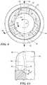
- Each slot 42has a floor or proximal surface 44 ( FIGS. 3 , 4, 4A ) facing generally in the downstream direction and forming the downstream wall of the slot 42.
- a floor surface 44 of each slot 42has a sufficient thickness to enable to the floor surface 44 to slope in the downstream direction D from a point along the slot 42 proximate the exterior surface 40 to the juncture between the slot 42 and the interior wall of the inflow cannula 18. For example, FIG.
- each slot 42illustrates a 30 degree slope in the floor surface 44 in the downstream direction, although slopes in the range from greater than 0 degrees to 90 degrees are contemplated.
- the cross-sectional area of each slot 42increases progressively in the inward direction, toward axis 22.
- the floor surface 44 of each slot 42also in angled in downstream in the circumferential direction CC. That is, the inflow cannula 18 defines the axis 22 and minor longitudinal axis 46 perpendicular to the axis 22.
- Each of the plurality of slotsmay be sloped in the first direction CC with respect to the axis 22 and/or angled in the first direction CC with respect to the minor longitudinal axis 46.
- Each slot 42also has side surfaces 48 defined by edges of the slots 42, extending upstream from floor surface 44 and bounding the slots 42 on circumferentially opposite sides. These side surfaces 48 extend generally upstream and downstream, but flare outwardly, away from one another adjacent the upstream extremities of the slots and slots.
- the surfaces of the slots 42, and the slots 42generally, are rounded and smooth at the exterior surface 40 of the inflow cannula 18 and at the upstream extremities of the slots 42.
- the rotor 32rotates in a clockwise direction.
- the rotor 32may be configure to impel blood in a direction parallel to the axis 22 as opposed to perpendicular to axis 22.
- each of the slots 42may be angled and sloped, as described above, in the clockwise direction.
- the slots 42may further be of uniform size or alternatively may vary in size.
- the aspect ratio of each of the slots 42is between 1:1 and 2:1, and in an exemplary configuration, 1.22:1.
- the surface area of the slots 42is equal to or greater than the surface area defined by the interior flow of the inflow cannula 18. That is the sum of all the surface areas of each slot 42, independent of the number of slots 42, is greater than the cross-sectional area of the lumen of the inflow cannula 18.
- This configurationcombined with the slots 42 being angled and sloped in the direction of rotation CC of the rotor may result in increased washing efficiency around the exterior surface 40 of the inflow cannula 18 when in implanted within the heart, by around 25%, as compared to an un-crenellated design, which further prevents the formation of thrombus.
- the washing efficiencyincreases around the exterior surface 40 of the inflow cannula 18 linearly for about 300 microns radially outward from the inflow cannula 18, when the pump is implanted within the left ventricle.
- pump 10is implanted in a mammalian subject, such as a human patient, so that the upstream end 26 of inflow cannula 18 projects into a chamber of the heart, such as the left ventricle (LV), as depicted schematically in FIG. 5 .
- a mounting ringsuch as a mounting ring 50 may be attached to an exterior surface of the heart wall as, for example, by suturing it to the heart wall adjacent the apex of the heart.
- a holemay be formed through the heart wall within the mounting ring.
- the inflow cannula 18is advanced through the mounting ring and through the hole in the heart wall, and a clamp (not shown) incorporated in the mounting ring 50 is actuated so that the mounting ring grips the outlet structure, thus attaching the pump to the mounting ring and to the heart.
- the first portion 14 and the second portion 16are disposed outside of the heart.
- An outlet cannulasuch as a flexible tubular outlet cannula (not shown) is connected between the outlet 24 and an artery such as the aorta.
- Pump 10is operatively connected to a controller 52, as, for example, by electrically connecting the controller to the pump via connector 54 ( FIG.1 ) so that the controller can actuate the pump and control its operation. Controller 52 may be mounted within or outside of the patient's body.
- the controller 52adjusts the electric power supplied to the pump 10 so as to maintain the rotor speed and hence the average blood flow through the pump 10 at a value less than the entire flow of blood entering the left ventricle over time. That is, the heart itself performs some of the pumping action necessary to pump blood into the aorta against the prevailing arterial blood pressure. In this normal condition, the pressure prevailing within the left ventricle is at least slightly above the pressure prevailing around the outside of the heart throughout the cardiac cycle.
- the pumpdraws in blood through the inflow cannula 18.
- a substantial portion of the blood entering the inflow cannulapasses in the downstream direction through upstream end 26 and passes through the flow path of the pump to the outlet.
- the blood flowing through the slots 42imparts angular momentum or swirl about axis 22 to the flow as a whole.
- the actual direction of swirlis the counter-clockwise direction CC shown in FIG. 6 , co-directional with the counter0clockwise rotation of the rotor.
- This swirlimproves the hydrodynamic efficiency of the pump 10.
- swirl counter-directional to the rotational direction of the rotorcan provide improved hydrodynamic efficiency.
- the walls bounding the heart chambersuch as the interventricular septum IVS and the outside wall of the wall VW bounding left ventricle LV, remain remote from the upstream end 26 of the inflow cannula 18.
- Changes in the patient's physiologyas, for example, changes in the prevailing arterial pressure, the patient's state of activity, or other changes in the body, may decrease the average rate of flow into the left ventricle, increase the rate of flow from the left ventricle to the aorta, or both.
- the ventriclein continually drained of blood. This may cause the walls bounding the ventricle to collapse towards one another. This is referred to as a suction condition.
- one or more of the wallsmay overlie the upstream end 26 of the inflow cannula 18 and thus fully or partially close the inflow cannula 18.
- bloodwill continue to flow into the pump through slots 42. While one or more of the slots 42 may be blocked in this condition, it is unlikely for the walls to collapse in such a manner as to block all of the slots and the upstream opening simultaneously.
- the inlet to the pumpwill remain at least partially open.
- the controller 52 associated with the pump 10is configured to detect a suction condition and to vary the operation of the pump 10 so as to relieve the suction condition.
- controller 52may detect changes in flow through the pump, power consumption by the pump, pressure prevailing within the pump 10 or within the chamber, flow rate through the pump 10 or other operational parameters.
- the controller 52may be configured to temporarily reduce the operating speed of the pump in response to a suction condition. Suction detection and correction may be performed, for example, by a controller as taught in U.S. Published Patent Application No. 2015/0367048 ).
- the suction-detecting controller and the inflow cannula 18cooperate to provide effective relief of suction conditions.
- the inflow cannula 18can be applied to other pumps.
- an inflow cannula 18 as described hereincan be provided on an axial flow blood pump.
- Certain axial flow blood pumpsare described in U.S. Patent No. 8,007,254 , have a generally straight, tubular housing, so that one end of the tubular structure forms the inflow cannula 18 whereas the other end forms the outlet.
- the impelleris arranged to rotate around the axis of the housing and to impel blood in a downstream direction through the flow path defined by the structure.
- the inflow cannula 18may be modified to include slots and slots as described herein.
- axial flow blood pumpsare positioned with the inflow cannula 18 inside a heart chamber such as the ventricle and with the outlet end of the pump outside of the heart, so that the outlet structure is connected to an artery such as the aorta via a flexible inlet cannula in much the same manner as described above with reference to FIG. 5 .
- axial flow blood pumps of this naturecan be mounted with the entire housing of the pump disposed within the ventricle.
- an axial flow blood pumpmay be mounted inside the heart chamber and retained in place by a rigid elongated member extending from the inlet end of the pump to a fixation device mounted on the heart wall.
- the outlet of the pumptypically is connected to an outlet cannula that extends out of the ventricle into the aorta through the aortic valve of the heart.
- the inlet of the pumpmay be provided with slots and slots as discussed herein.
Landscapes
- Health & Medical Sciences (AREA)
- Heart & Thoracic Surgery (AREA)
- Engineering & Computer Science (AREA)
- Cardiology (AREA)
- Life Sciences & Earth Sciences (AREA)
- Anesthesiology (AREA)
- Biomedical Technology (AREA)
- Hematology (AREA)
- Mechanical Engineering (AREA)
- Animal Behavior & Ethology (AREA)
- General Health & Medical Sciences (AREA)
- Public Health (AREA)
- Veterinary Medicine (AREA)
- Vascular Medicine (AREA)
- Physics & Mathematics (AREA)
- Fluid Mechanics (AREA)
- External Artificial Organs (AREA)
Description
- The present invention relates to implantable blood pumps, and in particular, a blood pump having a crenelated inflow cannula.
- Blood pumps are commonly used as elements of mechanical circulatory support devices or "MCSDs." MCSDs are normally used to aid the pumping action of a diseased heart. An MCSD that is arranged to aid the pumping action of a ventricle is also referred to as a ventricular assist device or "VAD" (eg. see
WO2010/008560 ). - A blood pump used in an MCSD typically is implanted within the patient, with the inlet of the pump communicating with a chamber of the heart, such as a ventricle and with the outlet of the pump connected to an artery. The pump is actuated to draw blood from the ventricle and pump it into the artery. The heart continues to beat, so that some blood may also be passed out of the ventricle through a valve such as the aortic valve. A condition referred to as a "suction" condition can occur when VAD tries to draw more blood than is available. When such a suction condition occurs, the chamber of the heart may collapse, so that a wall of the chamber is drawn toward the pump inlet and blocks the inlet. In extreme cases, such a condition can cause bruising or other injury to heart tissue. Moreover, the chamber wall may remain in place at the pump inlet for some time after the imbalance in flow has been corrected. Accordingly, MCSDs commonly incorporate control circuitry that maintains the flow through the pump at a safe value unlikely to cause a suction condition.
- The present invention, as claimed, advantageously provides a blood pump including a housing defining a fluid flow path. The housing defines an upstream end, a downstream end, and an outlet at the downstream end. A rotor is disposed within the housing and within the fluid flow path, the rotor being rotatable independent of the housing in a first direction and configured to pump blood downstream toward the outlet. The housing defines an inflow cannula at the upstream end, the inflow cannula defining a distal end proximate the rotor and an opposite proximal end. The inflow cannula further defines a major longitudinal axis and minor longitudinal axis, the proximal end of the inflow cannula defines a plurality of slots radially disposed about the proximal end, the plurality of slots being at least one from the group consisting of sloped in the first direction with respect to the major longitudinal axis and angled in the first direction with respect to the minor longitudinal axis.
- In another aspect of this embodiment, the housing defines a rotor space, and wherein the rotor is disposed within the rotor space, and wherein the inflow cannula is mounted in fixed spatial relationship with the rotor space.
- In another aspect of this embodiment, the rotor defines a plurality of fluid flow slots, and wherein the number of slots in the plurality of fluid flow slots is different than the number of slots in the plurality of slots.
- In another aspect of this embodiment, the plurality of slots are open-ended on the proximal most end of the inflow cannula.
- In another aspect of this embodiment, the rotor is an impeller configured to impel fluid along the major longitudinal axis.
- In another aspect of this embodiment, the rotor is an impeller configured to impel fluid perpendicular to the major longitudinal axis.
- According to the invention, each of the plurality of slots has a cross-sectional area which increases in an inward direction from the exterior of the inflow cannula.
- In another aspect of this embodiment, the inflow cannula defines a lumen there through, and wherein total cross-sectional area of the plurality of slots is greater than a cross-sectional area of the lumen.
- In another aspect of this embodiment, each of the plurality of slots defines a width transverse to the inward direction and the width of each of the plurality of slots increases toward the upstream end.
- In another aspect of this embodiment, the plurality of slots are equally spaced about the proximal end of the inflow cannula.
- In another aspect of this embodiment, the inflow cannula is sized to be implanted within a heart of a patient.
- In another aspect of this embodiment, the aspect ratio of each of the plurality of slots is between 1:1 and 2:1.
- In an embodiment of a blood pump, a blood pump includes a housing defining a fluid flow path. The housing defines an upstream end, a downstream end, and an outlet at the downstream end. A rotor is disposed within the housing and within the fluid flow path. The rotor is rotatable independent of the housing in a first direction and configured to pump blood downstream toward the outlet. The housing defines an inflow cannula at the upstream end, the inflow cannula defining a lumen there through in fluid communication with the outlet end and defining a cross-sectional area. The inflow cannula defines a distal end proximate the rotor and an opposite proximal end, the proximal end of the inflow cannula defining a plurality of open-ended slots radially disposed about the proximal end, the plurality of open-ended slots being angled in the first direction and defining a cross-sectional area greater than the cross-sectional area of the lumen.
- In another aspect of this embodiment, a stator is disposed within the housing and has a plurality of electromagnetic coils, the stator is configured to generate an electromagnetic field to rotate the rotor,
- In another aspect of this embodiment, the rotor defines a plurality of fluid flow slots, and wherein the number of slots in the plurality of fluid flow slots is different than the number of slots in the plurality of slots.
- In another aspect of this embodiment, the rotor is an impeller configured to impel fluid along the major longitudinal axis.
- In another aspect of this embodiment, rotor is an impeller configured to impel fluid perpendicular to the major longitudinal axis.
- In another aspect of this embodiment, each of the plurality of slots has a cross-sectional area which increases in an inward direction from the exterior of the inflow cannula.
- In another aspect of this embodiment, a total cross-sectional area of the plurality of slots is greater than a cross-sectional area of the lumen.
- In an embodiment of a blood pump, a blood pump includes a housing defining a fluid flow path. The housing defines an upstream end, a downstream end, and an outlet at the downstream end. A rotor is disposed within the housing and within the fluid flow path, the rotor is rotatable independent of the housing in a first direction and configured to pump blood downstream toward the outlet. The housing defines an inflow cannula at the upstream end, the inflow cannula defines a lumen there through in fluid communication with the outlet end and defining a cross-sectional area. The inflow cannula defining a distal end proximate the rotor and an opposite proximal end, the proximal end of the inflow cannula defining a plurality of open-ended slots radially disposed about the proximal end, the plurality of slots being sloped in the first direction with respect to the major longitudinal axis; angled in the first direction with respect to the minor longitudinal axis; and defining a total cross-sectional area greater than a cross-sectional area of the lumen. The rotor defines a plurality of fluid flow slots, and wherein the number of slots in the plurality of fluid flow slots is different than the number of slots in the plurality of slots.
- A more complete understanding of the present invention, and the attendant advantages and features thereof, will be more readily understood by reference to the following detailed description when considered in conjunction with the accompanying drawings wherein:
FIG. 1 is a diagrammatic, exploded, perspective view of a blood pump according to one embodiment of the disclosure;FIG. 2 is a front view of the cannula shown inFIG. 1 ;FIG. 3 is a top perspective view of the cannula shown inFIG. 2 ;FIG. 4 is a top view of the cannula shown inFIG. 2 ;FIG. 4A is a cross-sectional view acrossSection 4A-4A shown inFIG. 4 ;FIG. 5 is a diagrammatic view depicting a heart with the pump ofFIG. 1 implanted therein; andFIG. 6 is an assembled view of the blood pump shown inFIG. 1 .- Referring now to the drawings in which like reference designators refer to like elements there is shown in
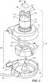
FIG. 1 an exemplary blood pump constructed in accordance with the principles of the present application and designated generally "10. Theblood pump 10 according to one embodiment of the disclosure includes a static structure orhousing 12 which houses the components of theblood pump 10. In one configuration, thehousing 12 includes a lower housing orfirst portion 14, an upper housing orsecond portion 16, and an inlet portion orinflow cannula 18. Thefirst portion 14 and thesecond portion 16 cooperatively define a volute-shaped chamber 20 having a majorlongitudinal axis 22 extending through the first portion andinflow cannula 18. Thechamber 20 defines a radius that increases progressively around theaxis 22 to an outlet location on the periphery of thechamber 20. Thefirst portion 14 and thesecond portion 16 define anoutlet 24 in communication withchamber 20. Thefirst portion 14 and thesecond portion 16 also define isolated chambers (not shown) separated from thevolute chamber 20 by magnetically permeable walls. - Referring now to
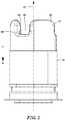
FIGS. 1 , and2 , theinflow cannula 18 is generally cylindrical and extends fromfirst portion 14 and extends generally alongaxis 22. Theinflow cannula 18 has to an upstream end orproximal end 26 remote fromsecond portion 16 and a downstream end ordistal end 28 proximate thechamber 20. The parts of thehousing 12 mentioned above are fixedly connected to one another so that thehousing 12 as a whole defines a continuous enclosed flow path. The flow path extends from upstream end 26 (best seen inFIG.2 ) at the upstream end of the flow path to theoutlet 24 at the downstream end of the flow path. The upstream and downstream directions along the flow path are indicated inFIG. 2 by the arrows U and D respectively. Apost 30 is mounted tofirst portion 14 alongaxis 22. A generally disc-shapedferromagnetic rotor 32 with acentral hole 34 is mounted withinchamber 20 for rotation about theaxis 22.Rotor 32 includes a permanent magnet and also includes flow channels for transferring blood from adjacent the center of the rotor to the periphery of the rotor. In the assembled condition, post 30 is received in the central hole of therotor 32. Components such as permanent magnets electromagnetic coils may be disposed within thefirst portion 14 and thesecond portion 16 and in fluidly isolated chambers An electrical connector 41 (FIG.1 ) is provided onfirst portion 14 for connecting the coils to a source of power such as a controller (not shown). The controller is arranged to apply power to the coils of the pump to create a rotating magnetic field which spinsrotor 32 aroundaxis 22 in a predetermined first direction of rotation, such as the direction R indicated by the arrow inFIG. 1 ,i.e., counterclockwise as seen from the upstream end ofinflow cannula 18. In other configurations of theblood pump 10, the first direction may be clockwise, that is therotor 32 rotates in a clockwise direction and theslots 42 are angled and/or sloped in the clockwise direction. Rotation of therotor 32 impel blood downstream along the flow path so that the blood, moves in a downstream direction D along the flow path, and exits through theoutlet 24. During rotation, hydrodynamic and magnetic bearings (not shown) support therotor 32 and maintain therotor 32 out of contact with the surfaces of the elements of thefirst portion 14 and thesecond portion 16 during operation. The general arrangement of the components described above may be similar to theblood pump 10 used in the MCSD sold under the designation HVAD by Heartware, Inc., assignee of the present application. The arrangement of components such as the magnets, electromagnetic coils, and hydrodynamic bearings used in such a pump and variants of the same general design are described inU.S. Patent Nos. 6,688,861 ;7,575,423 ;7,976,271 ; and8,419,609 . - Continuing to refer to
FIGS. 1 and2 , theinflow cannula 18 defines a plurality ofprojections 36 extending in the upstream direction at theupstream end 26. Although threeprojections 36 are shown, any number ofprojections 36 may be included. In one configuration, theprojections 36 are spaced at equal intervals around the upstream-to-downstream axis 22 and in other configurations, theprojections 36 are unevenly spaced. Eachprojection 36 has aninterior surface 38 facing generally in a radially inward direction towardaxis 22 and anexterior surface 40 facing generally radially outwardly. The exterior surfaces 40 of theprojections 36 constitute an exterior surface of theinflow cannula 18.Projections 36 are spaced apart from one another so as to define correspondingslots 42 disposed between a pair ofprojections 36, defining a crenellated configuration. Theslots 42 may extend generally inwardly from theexterior surface 40 of the inflow cannula to the lumen of theinflow cannula 18. Any number ofslots 42 may be included and in one configuration, the number ofslots 42 is different than the number of fluid channels in therotor 32, whether greater or less than. For example, as shown inFIG. 1 , therotor 32 defines four fluid channels and inflow cannula defines threeslots 42. Eachslot 42 is in the form of a groove that is open at the upstream extremity of theinflow cannula 18,i.e., theslots 42 are bounded on three sides by theinflow cannula 18 but are open at the most proximal end of theinflow cannula 18. As best appreciated with reference toFIG. 4 , eachslot 42 slopes downstream in a circumferential direction CC aroundaxis 22. As further discussed below, the slope of theslots 42 imparts a swirl to blood entering the lumen of theinflow cannula 18 in the circumferential direction C. As depicted inFIGS. 1-4 , the circumferential direction CC is counter-clockwise aroundaxis 22 as seen inFIG. 4 , looking in the downstream direction alongaxis 22. The circumferential direction CC is the same as the rotational direction R (FIG.1 ) of therotor 32. Eachslot 42 has a floor or proximal surface 44 (FIGS. 3 ,4, 4A ) facing generally in the downstream direction and forming the downstream wall of theslot 42. As best appreciated with reference toFIG. 4A , afloor surface 44 of eachslot 42 has a sufficient thickness to enable to thefloor surface 44 to slope in the downstream direction D from a point along theslot 42 proximate theexterior surface 40 to the juncture between theslot 42 and the interior wall of theinflow cannula 18. For example,FIG. 4A illustrates a 30 degree slope in thefloor surface 44 in the downstream direction, although slopes in the range from greater than 0 degrees to 90 degrees are contemplated. Thus, the cross-sectional area of eachslot 42 increases progressively in the inward direction, towardaxis 22. Thefloor surface 44 of eachslot 42 also in angled in downstream in the circumferential direction CC. That is, theinflow cannula 18 defines theaxis 22 and minorlongitudinal axis 46 perpendicular to theaxis 22. Each of the plurality of slots may be sloped in the first direction CC with respect to theaxis 22 and/or angled in the first direction CC with respect to the minorlongitudinal axis 46. Eachslot 42 also has side surfaces 48 defined by edges of theslots 42, extending upstream fromfloor surface 44 and bounding theslots 42 on circumferentially opposite sides. These side surfaces 48 extend generally upstream and downstream, but flare outwardly, away from one another adjacent the upstream extremities of the slots and slots. The surfaces of theslots 42, and theslots 42 generally, are rounded and smooth at theexterior surface 40 of theinflow cannula 18 and at the upstream extremities of theslots 42. In other configurations, therotor 32 rotates in a clockwise direction. For example, therotor 32 may be configure to impel blood in a direction parallel to theaxis 22 as opposed to perpendicular toaxis 22. In such a configuration, each of theslots 42 may be angled and sloped, as described above, in the clockwise direction. Theslots 42 may further be of uniform size or alternatively may vary in size. In one configuration, the aspect ratio of each of theslots 42 is between 1:1 and 2:1, and in an exemplary configuration, 1.22:1. - In one configuration, the surface area of the
slots 42 is equal to or greater than the surface area defined by the interior flow of theinflow cannula 18. That is the sum of all the surface areas of eachslot 42, independent of the number ofslots 42, is greater than the cross-sectional area of the lumen of theinflow cannula 18. This configuration, combined with theslots 42 being angled and sloped in the direction of rotation CC of the rotor may result in increased washing efficiency around theexterior surface 40 of theinflow cannula 18 when in implanted within the heart, by around 25%, as compared to an un-crenellated design, which further prevents the formation of thrombus. For example, in one configuration, the washing efficiency increases around theexterior surface 40 of theinflow cannula 18 linearly for about 300 microns radially outward from theinflow cannula 18, when the pump is implanted within the left ventricle. - In a method according to a further aspect of the disclosure, pump 10 is implanted in a mammalian subject, such as a human patient, so that the
upstream end 26 ofinflow cannula 18 projects into a chamber of the heart, such as the left ventricle (LV), as depicted schematically inFIG. 5 . For example, a mounting ring such as a mountingring 50 may be attached to an exterior surface of the heart wall as, for example, by suturing it to the heart wall adjacent the apex of the heart. A hole may be formed through the heart wall within the mounting ring. Theinflow cannula 18 is advanced through the mounting ring and through the hole in the heart wall, and a clamp (not shown) incorporated in the mountingring 50 is actuated so that the mounting ring grips the outlet structure, thus attaching the pump to the mounting ring and to the heart. In an exemplary configuration, thefirst portion 14 and thesecond portion 16 are disposed outside of the heart. An outlet cannula such as a flexible tubular outlet cannula (not shown) is connected between theoutlet 24 and an artery such as the aorta.Pump 10 is operatively connected to acontroller 52, as, for example, by electrically connecting the controller to the pump via connector 54 (FIG.1 ) so that the controller can actuate the pump and control its operation.Controller 52 may be mounted within or outside of the patient's body. - With the pump mounted in place on the heart, electric power is supplied to the electromagnetic coils of the pump by
controller 52. The rotor 32 (FIG.1 ) rotates about thecentral axis 22 at a speed set by the controller, so that thepump 10 draws blood from within the ventricle LV and transfers it to the aorta. Typically, the controller adjusts the electric power supplied to thepump 10 so as to maintain the rotor speed and hence the average blood flow through thepump 10 at a value less than the entire flow of blood entering the left ventricle over time. That is, the heart itself performs some of the pumping action necessary to pump blood into the aorta against the prevailing arterial blood pressure. In this normal condition, the pressure prevailing within the left ventricle is at least slightly above the pressure prevailing around the outside of the heart throughout the cardiac cycle. - In this normal operating condition, the pump draws in blood through the
inflow cannula 18. Typically, a substantial portion of the blood entering the inflow cannula passes in the downstream direction throughupstream end 26 and passes through the flow path of the pump to the outlet. The blood flowing through theslots 42 imparts angular momentum or swirl aboutaxis 22 to the flow as a whole. As discussed above, in this embodiment, the actual direction of swirl is the counter-clockwise direction CC shown inFIG. 6 , co-directional with the counter0clockwise rotation of the rotor. This swirl improves the hydrodynamic efficiency of thepump 10. In other embodiments, with a different rotor configuration, swirl counter-directional to the rotational direction of the rotor can provide improved hydrodynamic efficiency. During normal operation, the walls bounding the heart chamber, such as the interventricular septum IVS and the outside wall of the wall VW bounding left ventricle LV, remain remote from theupstream end 26 of theinflow cannula 18. Changes in the patient's physiology as, for example, changes in the prevailing arterial pressure, the patient's state of activity, or other changes in the body, may decrease the average rate of flow into the left ventricle, increase the rate of flow from the left ventricle to the aorta, or both. In this condition, the ventricle in continually drained of blood. This may cause the walls bounding the ventricle to collapse towards one another. This is referred to as a suction condition. In the suction condition, one or more of the walls may overlie theupstream end 26 of theinflow cannula 18 and thus fully or partially close theinflow cannula 18. However, blood will continue to flow into the pump throughslots 42. While one or more of theslots 42 may be blocked in this condition, it is unlikely for the walls to collapse in such a manner as to block all of the slots and the upstream opening simultaneously. Thus, even in a suction condition, the inlet to the pump will remain at least partially open. - Continued operation of the pump may not cause an extreme drop in the pressure prevailing at the inlet to the flow path, just downstream of any partial blockage. This limits the differential pressure applied to the heart wall causing the blockage and thus limits the force tending to engage the heart wall with the inflow cannula. This, in turn, minimizes damage to the tissue of the heart wall that could be caused by forcible engagement with the inflow cannula. Moreover, limiting the force of engagement between the heart wall and the
inflow cannula 18 in the event of a suction condition makes it easier to detach the heart wall from theinflow cannula 18 when the suction condition is cleared and the blood reinflates the ventricle. The outward splay of theside surface 28 of theslots 42 and the gentle, rounded curves of the surfaces at the upstream extremity of theinflow cannula 18 also makes it easier to detach the heart wall from the inflow cannula when the suction condition is relieved. - The
controller 52 associated with thepump 10 is configured to detect a suction condition and to vary the operation of thepump 10 so as to relieve the suction condition. For example,controller 52 may detect changes in flow through the pump, power consumption by the pump, pressure prevailing within thepump 10 or within the chamber, flow rate through thepump 10 or other operational parameters. Thecontroller 52 may be configured to temporarily reduce the operating speed of the pump in response to a suction condition. Suction detection and correction may be performed, for example, by a controller as taught in U.S. Published Patent Application No.2015/0367048 ). - Stated another way, the suction-detecting controller and the
inflow cannula 18 cooperate to provide effective relief of suction conditions. - Numerous variations and combinations of the features discussed above can be utilized. For example, the number of slots and slots can be varied. The
inflow cannula 18 can be applied to other pumps. For example, aninflow cannula 18 as described herein can be provided on an axial flow blood pump. Certain axial flow blood pumps are described inU.S. Patent No. 8,007,254 , have a generally straight, tubular housing, so that one end of the tubular structure forms theinflow cannula 18 whereas the other end forms the outlet. The impeller is arranged to rotate around the axis of the housing and to impel blood in a downstream direction through the flow path defined by the structure. Here again, theinflow cannula 18 may be modified to include slots and slots as described herein. In some cases, axial flow blood pumps are positioned with theinflow cannula 18 inside a heart chamber such as the ventricle and with the outlet end of the pump outside of the heart, so that the outlet structure is connected to an artery such as the aorta via a flexible inlet cannula in much the same manner as described above with reference toFIG. 5 . In other cases, axial flow blood pumps of this nature can be mounted with the entire housing of the pump disposed within the ventricle. For example, as shown inU.S. Patent No. 8,852,072 , an axial flow blood pump may be mounted inside the heart chamber and retained in place by a rigid elongated member extending from the inlet end of the pump to a fixation device mounted on the heart wall. The outlet of the pump typically is connected to an outlet cannula that extends out of the ventricle into the aorta through the aortic valve of the heart. Here again, the inlet of the pump may be provided with slots and slots as discussed herein. - It will be appreciated by persons skilled in the art that the present invention is not limited to what has been particularly shown and described herein above. In addition, unless mention was made above to the contrary, it should be noted that all of the accompanying drawings are not to scale. Modifications and variations are possible in light of the above teachings without departing from the scope of the invention, which is limited only by the following claims.
Claims (14)
- A blood pump, comprising:a housing (12) defining a fluid flow path, the housing defining an upstream end, a downstream end, and an outlet at the downstream end;a rotor disposed within the housing and within the fluid flow path, the rotor being rotatable independent of the housing in a first direction and configured to pump blood downstream toward the outlet; andthe housing defining an inflow cannula at the upstream end, the inflow cannula defining a distal end proximate the rotor and an opposite proximal end, the inflow cannula further defining a major longitudinal axis (22) and minor longitudinal axis (46) perpendicular to the major longitudinal axis (22),the proximal end of inflow cannula defining a plurality of slots (42) radially disposed about the proximal end, the plurality of slots being at least one from the group consisting of sloped in the first direction with respect to the major longitudinal axis and angled in the first direction with respect to the minor longitudinal axis, each of the plurality of slots has a cross-sectional area which increases in an inward direction from the exterior of the inflow cannula.
- The blood pump of Claim 1, wherein the housing defines a rotor space, and
wherein the rotor is disposed within the rotor space, and wherein the inflow cannula is mounted in fixed spatial relationship with the rotor space. - The blood pump of Claims 1 or 2, wherein the rotor defines a plurality of fluid flow slots, and wherein the number of slots in the plurality of fluid flow slots is different than the number of slots in the plurality of slots.
- The blood pump of any one of Claims 1-3, wherein the plurality of slots are open-ended on the proximal most end of the inflow cannula.
- The blood pump of any one of Claims 1-4, wherein the rotor is an impeller configured to impel fluid along the major longitudinal axis.
- The blood pump of any one of Claims 1-5, wherein the rotor is an impeller configured to impel fluid perpendicular to the major longitudinal axis.
- The blood pump of any one of Claims 1-6, wherein the inflow cannula defines a lumen there through, and wherein total cross-sectional area of the plurality of slots is greater than a cross-sectional area of the lumen.
- The blood pump of any one of Claims 1-7, wherein each of the plurality of slots defines a width transverse to the inward direction and the width of each of the plurality of slots increases toward the upstream end.
- The blood pump of any one of Claims 1-8, wherein the plurality of slots are equally spaced about the proximal end of the inflow cannula.
- The blood pump of any one of Claims 1-9, wherein the inflow cannula is sized to be implanted within a heart of a patient.
- The blood pump of any one of Claims 1-10, wherein the aspect ratio of each of the plurality of slots is between 1:1 and 2:1.
- The blood pump of any one of Claim 1-11, wherein the plurality of slots are sloped in the first direction with respect to the major longitudinal axis.
- The blood pump of any one of Claim 1-12, wherein the plurality of slots are angled in the first direction with respect to the minor longitudinal axis.
- The blood pump of any one of Claims 1-13, further including a stator disposed within the housing and having a plurality of electromagnetic coils, the stator being configured to generate an electromagnetic field to rotate the rotor.
Applications Claiming Priority (2)
| Application Number | Priority Date | Filing Date | Title |
|---|---|---|---|
| US201662315758P | 2016-03-31 | 2016-03-31 | |
| PCT/US2017/024693WO2017172876A1 (en) | 2016-03-31 | 2017-03-29 | Crenellated inflow cannula |
Publications (2)
| Publication Number | Publication Date |
|---|---|
| EP3436104A1 EP3436104A1 (en) | 2019-02-06 |
| EP3436104B1true EP3436104B1 (en) | 2021-04-28 |
Family
ID=58489768
Family Applications (1)
| Application Number | Title | Priority Date | Filing Date |
|---|---|---|---|
| EP17716042.1AActiveEP3436104B1 (en) | 2016-03-31 | 2017-03-29 | Crenellated inflow cannula |
Country Status (4)
| Country | Link |
|---|---|
| US (1) | US10525179B2 (en) |
| EP (1) | EP3436104B1 (en) |
| CN (2) | CN118543021A (en) |
| WO (1) | WO2017172876A1 (en) |
Families Citing this family (25)
| Publication number | Priority date | Publication date | Assignee | Title |
|---|---|---|---|---|
| CA3066361A1 (en) | 2017-06-07 | 2018-12-13 | Shifamed Holdings, Llc | Intravascular fluid movement devices, systems, and methods of use |
| WO2019094963A1 (en) | 2017-11-13 | 2019-05-16 | Shifamed Holdings, Llc | Intravascular fluid movement devices, systems, and methods of use |
| DE102018201030B4 (en) | 2018-01-24 | 2025-10-16 | Kardion Gmbh | Magnetic dome element with magnetic bearing function |
| CN112004563B (en) | 2018-02-01 | 2024-08-06 | 施菲姆德控股有限责任公司 | Intravascular blood pump and methods of use and manufacture |
| DE102018207611A1 (en) | 2018-05-16 | 2019-11-21 | Kardion Gmbh | Rotor bearing system |
| DE102018207575A1 (en) | 2018-05-16 | 2019-11-21 | Kardion Gmbh | Magnetic face turning coupling for the transmission of torques |
| DE102018208541A1 (en) | 2018-05-30 | 2019-12-05 | Kardion Gmbh | Axial pump for a cardiac assist system and method of making an axial pump for a cardiac assist system |
| DE102018208550A1 (en) | 2018-05-30 | 2019-12-05 | Kardion Gmbh | A lead device for directing blood flow to a cardiac assist system, cardiac assist system, and method of making a lead device |
| DE102018208538A1 (en) | 2018-05-30 | 2019-12-05 | Kardion Gmbh | Intravascular blood pump and process for the production of electrical conductors |
| DE102018208539A1 (en) | 2018-05-30 | 2019-12-05 | Kardion Gmbh | A motor housing module for sealing an engine compartment of a motor of a cardiac assist system and cardiac assistance system and method for mounting a cardiac assist system |
| DE102018210076A1 (en) | 2018-06-21 | 2019-12-24 | Kardion Gmbh | Method and device for detecting a state of wear of a cardiac support system, method and device for operating a cardiac support system and cardiac support system |
| DE102018210058A1 (en) | 2018-06-21 | 2019-12-24 | Kardion Gmbh | Stator blade device for guiding the flow of a fluid flowing out of an outlet opening of a heart support system, heart support system with stator blade device, method for operating a stator blade device and manufacturing method |
| DE102018211327A1 (en) | 2018-07-10 | 2020-01-16 | Kardion Gmbh | Impeller for an implantable vascular support system |
| DE102018212153A1 (en) | 2018-07-20 | 2020-01-23 | Kardion Gmbh | Inlet line for a pump unit of a cardiac support system, cardiac support system and method for producing an inlet line for a pump unit of a cardiac support system |
| US12161857B2 (en) | 2018-07-31 | 2024-12-10 | Shifamed Holdings, Llc | Intravascular blood pumps and methods of use |
| CN112654389A (en) | 2018-08-07 | 2021-04-13 | 开迪恩有限公司 | Bearing device for a cardiac support system and method for flushing an intermediate space in a bearing device for a cardiac support system |
| WO2020073047A1 (en) | 2018-10-05 | 2020-04-09 | Shifamed Holdings, Llc | Intravascular blood pumps and methods of use |
| US11318295B2 (en)* | 2019-02-28 | 2022-05-03 | Heartware, Inc. | HVAD rinse via a non-uniform thrust bearing gap |
| WO2021011473A1 (en) | 2019-07-12 | 2021-01-21 | Shifamed Holdings, Llc | Intravascular blood pumps and methods of manufacture and use |
| US11654275B2 (en) | 2019-07-22 | 2023-05-23 | Shifamed Holdings, Llc | Intravascular blood pumps with struts and methods of use and manufacture |
| WO2021062265A1 (en) | 2019-09-25 | 2021-04-01 | Shifamed Holdings, Llc | Intravascular blood pump systems and methods of use and control thereof |
| EP4501393A3 (en) | 2019-09-25 | 2025-04-09 | Shifamed Holdings, LLC | Catheter blood pumps and collapsible pump housings |
| US12121713B2 (en) | 2019-09-25 | 2024-10-22 | Shifamed Holdings, Llc | Catheter blood pumps and collapsible blood conduits |
| EP4072650A4 (en) | 2019-12-11 | 2024-01-10 | Shifamed Holdings, LLC | Descending aorta and vena cava blood pumps |
| DE102020102474A1 (en) | 2020-01-31 | 2021-08-05 | Kardion Gmbh | Pump for conveying a fluid and method for manufacturing a pump |
Family Cites Families (29)
| Publication number | Priority date | Publication date | Assignee | Title |
|---|---|---|---|---|
| US5972030A (en) | 1993-02-22 | 1999-10-26 | Heartport, Inc. | Less-invasive devices and methods for treatment of cardiac valves |
| US5840070A (en) | 1996-02-20 | 1998-11-24 | Kriton Medical, Inc. | Sealless rotary blood pump |
| US6159178A (en) | 1998-01-23 | 2000-12-12 | Heartport, Inc. | Methods and devices for occluding the ascending aorta and maintaining circulation of oxygenated blood in the patient when the patient's heart is arrested |
| US5928253A (en) | 1998-03-13 | 1999-07-27 | Cardiothoracic Systems, Inc. | Integrated cannula and vascular clamp assembly |
| US6129713A (en) | 1998-08-11 | 2000-10-10 | Embol-X, Inc. | Slidable cannula and method of use |
| US6033420A (en) | 1998-09-02 | 2000-03-07 | Embol-X, Inc. | Trocar introducer system and methods of use |
| US7526342B2 (en) | 1999-08-10 | 2009-04-28 | Maquet Cardiovascular Llc | Apparatus for endoscopic cardiac mapping and lead placement |
| US6712797B1 (en) | 2000-09-19 | 2004-03-30 | Board Of Supervisors Of Louisiana State University And Agricultural And Mechanical College | Blood return catheter |
| US6978176B2 (en) | 2001-12-08 | 2005-12-20 | Lattouf Omar M | Treatment for patient with congestive heart failure |
| US7247162B1 (en) | 2002-01-14 | 2007-07-24 | Edwards Lifesciences Corporation | Direct access atherectomy devices |
| US6732501B2 (en) | 2002-06-26 | 2004-05-11 | Heartware, Inc. | Ventricular connector |
| US7686758B2 (en)* | 2002-09-10 | 2010-03-30 | Hitmac (Usa), Inc. | Cannula tip for a cardiac assist device |
| EP1687056B9 (en) | 2003-11-20 | 2013-09-11 | Children's Medical Center Corporation | Trocar for use during endoscopy |
| US8419609B2 (en) | 2005-10-05 | 2013-04-16 | Heartware Inc. | Impeller for a rotary ventricular assist device |
| US8157833B2 (en) | 2005-11-09 | 2012-04-17 | Applied Medical Resources Corporation | Trocars with advanced fixation |
| EP1977110B8 (en)* | 2006-01-13 | 2018-12-26 | HeartWare, Inc. | Rotary blood pump |
| AU2008219653B2 (en)* | 2007-02-26 | 2014-01-16 | Heartware, Inc. | Intravascular ventricular assist device |
| AU2013273663B2 (en)* | 2007-02-26 | 2015-07-30 | Heartware, Inc. | Intravascular ventricular assist device |
| US8152493B2 (en)* | 2007-04-30 | 2012-04-10 | Hearthware Inc. | Centrifugal rotary blood pump with impeller having a hydrodynamic thrust bearing surface |
| US9199020B2 (en)* | 2007-11-01 | 2015-12-01 | Abiomed, Inc. | Purge-free miniature rotary pump |
| WO2009099644A1 (en) | 2008-02-08 | 2009-08-13 | Heartware, Inc. | Ventricular assist device for intraventricular placement |
| KR101537523B1 (en) | 2008-07-16 | 2015-07-17 | 하트웨어, 인코포레이티드 | Cannula tip for use with a vad |
| US8157812B2 (en) | 2008-09-10 | 2012-04-17 | Suros Surgical Systems, Inc. | Slotted deployment device |
| US8298185B2 (en) | 2010-09-14 | 2012-10-30 | Suremka Medical, Llc | Retractable cannula for surgical procedures |
| US9724500B2 (en) | 2011-12-09 | 2017-08-08 | Circulite, Inc. | By-pass shunt to reduce flow output of circulatory assist device |
| US9636441B2 (en)* | 2012-11-05 | 2017-05-02 | Robert Jarvik | Support stent for transvalvular conduit |
| KR20150126877A (en)* | 2013-03-07 | 2015-11-13 | 서클라이트, 인크. | Transseptal cannula, tip, delivery system, and method |
| EP3076884B1 (en)* | 2013-12-04 | 2020-02-05 | Heartware, Inc. | Apparatus for cutting an atrial wall |
| CN107073183A (en) | 2014-06-18 | 2017-08-18 | 心脏器械股份有限公司 | Method and apparatus for recognizing suction event |
- 2017
- 2017-03-29EPEP17716042.1Apatent/EP3436104B1/enactiveActive
- 2017-03-29WOPCT/US2017/024693patent/WO2017172876A1/ennot_activeCeased
- 2017-03-29USUS15/472,669patent/US10525179B2/enactiveActive
- 2017-03-29CNCN202410760332.3Apatent/CN118543021A/enactivePending
- 2017-03-29CNCN201780020477.8Apatent/CN108883217A/enactivePending
Non-Patent Citations (1)
| Title |
|---|
| None* |
Also Published As
| Publication number | Publication date |
|---|---|
| US10525179B2 (en) | 2020-01-07 |
| EP3436104A1 (en) | 2019-02-06 |
| CN108883217A (en) | 2018-11-23 |
| CN118543021A (en) | 2024-08-27 |
| WO2017172876A1 (en) | 2017-10-05 |
| US20170281841A1 (en) | 2017-10-05 |
Similar Documents
| Publication | Publication Date | Title |
|---|---|---|
| EP3436104B1 (en) | Crenellated inflow cannula | |
| US20210290938A1 (en) | Thrombus diverter concept | |
| US10251985B2 (en) | Axial flow pump with multi-grooved rotor | |
| EP2145108B1 (en) | Centrifugal rotary blood pump | |
| EP2438936B1 (en) | Blood pump | |
| EP2359007B1 (en) | Centrifugal pump with offset volute | |
| EP2167158B1 (en) | Reduced diameter axial rotary pump for cardiac assist | |
| EP1931403B1 (en) | Axial flow pump with multi-grooved rotor | |
| AU2013205145B2 (en) | Axial flow pump with multi-grooved rotor | |
| WO2013033783A1 (en) | Fluid transport apparatus | |
| AU2013257469B2 (en) | Axial flow pump with multi-grooved rotor | |
| JP7686740B2 (en) | Load-improving blood pump system and blood pump thereof | |
| WO2019079275A1 (en) | Impeller for artificial heart blood pumps |
Legal Events
| Date | Code | Title | Description |
|---|---|---|---|
| STAA | Information on the status of an ep patent application or granted ep patent | Free format text:STATUS: UNKNOWN | |
| STAA | Information on the status of an ep patent application or granted ep patent | Free format text:STATUS: THE INTERNATIONAL PUBLICATION HAS BEEN MADE | |
| PUAI | Public reference made under article 153(3) epc to a published international application that has entered the european phase | Free format text:ORIGINAL CODE: 0009012 | |
| STAA | Information on the status of an ep patent application or granted ep patent | Free format text:STATUS: REQUEST FOR EXAMINATION WAS MADE | |
| 17P | Request for examination filed | Effective date:20181023 | |
| AK | Designated contracting states | Kind code of ref document:A1 Designated state(s):AL AT BE BG CH CY CZ DE DK EE ES FI FR GB GR HR HU IE IS IT LI LT LU LV MC MK MT NL NO PL PT RO RS SE SI SK SM TR | |
| AX | Request for extension of the european patent | Extension state:BA ME | |
| DAV | Request for validation of the european patent (deleted) | ||
| DAX | Request for extension of the european patent (deleted) | ||
| GRAP | Despatch of communication of intention to grant a patent | Free format text:ORIGINAL CODE: EPIDOSNIGR1 | |
| STAA | Information on the status of an ep patent application or granted ep patent | Free format text:STATUS: GRANT OF PATENT IS INTENDED | |
| INTG | Intention to grant announced | Effective date:20201210 | |
| GRAS | Grant fee paid | Free format text:ORIGINAL CODE: EPIDOSNIGR3 | |
| GRAA | (expected) grant | Free format text:ORIGINAL CODE: 0009210 | |
| STAA | Information on the status of an ep patent application or granted ep patent | Free format text:STATUS: THE PATENT HAS BEEN GRANTED | |
| AK | Designated contracting states | Kind code of ref document:B1 Designated state(s):AL AT BE BG CH CY CZ DE DK EE ES FI FR GB GR HR HU IE IS IT LI LT LU LV MC MK MT NL NO PL PT RO RS SE SI SK SM TR | |
| REG | Reference to a national code | Ref country code:GB Ref legal event code:FG4D | |
| REG | Reference to a national code | Ref country code:CH Ref legal event code:EP | |
| REG | Reference to a national code | Ref country code:DE Ref legal event code:R096 Ref document number:602017037560 Country of ref document:DE | |
| REG | Reference to a national code | Ref country code:AT Ref legal event code:REF Ref document number:1386400 Country of ref document:AT Kind code of ref document:T Effective date:20210515 | |
| REG | Reference to a national code | Ref country code:IE Ref legal event code:FG4D | |
| REG | Reference to a national code | Ref country code:LT Ref legal event code:MG9D | |
| REG | Reference to a national code | Ref country code:AT Ref legal event code:MK05 Ref document number:1386400 Country of ref document:AT Kind code of ref document:T Effective date:20210428 | |
| PG25 | Lapsed in a contracting state [announced via postgrant information from national office to epo] | Ref country code:HR Free format text:LAPSE BECAUSE OF FAILURE TO SUBMIT A TRANSLATION OF THE DESCRIPTION OR TO PAY THE FEE WITHIN THE PRESCRIBED TIME-LIMIT Effective date:20210428 Ref country code:AT Free format text:LAPSE BECAUSE OF FAILURE TO SUBMIT A TRANSLATION OF THE DESCRIPTION OR TO PAY THE FEE WITHIN THE PRESCRIBED TIME-LIMIT Effective date:20210428 Ref country code:BG Free format text:LAPSE BECAUSE OF FAILURE TO SUBMIT A TRANSLATION OF THE DESCRIPTION OR TO PAY THE FEE WITHIN THE PRESCRIBED TIME-LIMIT Effective date:20210728 Ref country code:NL Free format text:LAPSE BECAUSE OF FAILURE TO SUBMIT A TRANSLATION OF THE DESCRIPTION OR TO PAY THE FEE WITHIN THE PRESCRIBED TIME-LIMIT Effective date:20210428 Ref country code:LT Free format text:LAPSE BECAUSE OF FAILURE TO SUBMIT A TRANSLATION OF THE DESCRIPTION OR TO PAY THE FEE WITHIN THE PRESCRIBED TIME-LIMIT Effective date:20210428 Ref country code:FI Free format text:LAPSE BECAUSE OF FAILURE TO SUBMIT A TRANSLATION OF THE DESCRIPTION OR TO PAY THE FEE WITHIN THE PRESCRIBED TIME-LIMIT Effective date:20210428 | |
| PG25 | Lapsed in a contracting state [announced via postgrant information from national office to epo] | Ref country code:LV Free format text:LAPSE BECAUSE OF FAILURE TO SUBMIT A TRANSLATION OF THE DESCRIPTION OR TO PAY THE FEE WITHIN THE PRESCRIBED TIME-LIMIT Effective date:20210428 Ref country code:GR Free format text:LAPSE BECAUSE OF FAILURE TO SUBMIT A TRANSLATION OF THE DESCRIPTION OR TO PAY THE FEE WITHIN THE PRESCRIBED TIME-LIMIT Effective date:20210729 Ref country code:IS Free format text:LAPSE BECAUSE OF FAILURE TO SUBMIT A TRANSLATION OF THE DESCRIPTION OR TO PAY THE FEE WITHIN THE PRESCRIBED TIME-LIMIT Effective date:20210828 Ref country code:PL Free format text:LAPSE BECAUSE OF FAILURE TO SUBMIT A TRANSLATION OF THE DESCRIPTION OR TO PAY THE FEE WITHIN THE PRESCRIBED TIME-LIMIT Effective date:20210428 Ref country code:NO Free format text:LAPSE BECAUSE OF FAILURE TO SUBMIT A TRANSLATION OF THE DESCRIPTION OR TO PAY THE FEE WITHIN THE PRESCRIBED TIME-LIMIT Effective date:20210728 Ref country code:PT Free format text:LAPSE BECAUSE OF FAILURE TO SUBMIT A TRANSLATION OF THE DESCRIPTION OR TO PAY THE FEE WITHIN THE PRESCRIBED TIME-LIMIT Effective date:20210830 Ref country code:SE Free format text:LAPSE BECAUSE OF FAILURE TO SUBMIT A TRANSLATION OF THE DESCRIPTION OR TO PAY THE FEE WITHIN THE PRESCRIBED TIME-LIMIT Effective date:20210428 Ref country code:RS Free format text:LAPSE BECAUSE OF FAILURE TO SUBMIT A TRANSLATION OF THE DESCRIPTION OR TO PAY THE FEE WITHIN THE PRESCRIBED TIME-LIMIT Effective date:20210428 | |
| REG | Reference to a national code | Ref country code:NL Ref legal event code:MP Effective date:20210428 | |
| PG25 | Lapsed in a contracting state [announced via postgrant information from national office to epo] | Ref country code:SM Free format text:LAPSE BECAUSE OF FAILURE TO SUBMIT A TRANSLATION OF THE DESCRIPTION OR TO PAY THE FEE WITHIN THE PRESCRIBED TIME-LIMIT Effective date:20210428 Ref country code:SK Free format text:LAPSE BECAUSE OF FAILURE TO SUBMIT A TRANSLATION OF THE DESCRIPTION OR TO PAY THE FEE WITHIN THE PRESCRIBED TIME-LIMIT Effective date:20210428 Ref country code:DK Free format text:LAPSE BECAUSE OF FAILURE TO SUBMIT A TRANSLATION OF THE DESCRIPTION OR TO PAY THE FEE WITHIN THE PRESCRIBED TIME-LIMIT Effective date:20210428 Ref country code:EE Free format text:LAPSE BECAUSE OF FAILURE TO SUBMIT A TRANSLATION OF THE DESCRIPTION OR TO PAY THE FEE WITHIN THE PRESCRIBED TIME-LIMIT Effective date:20210428 Ref country code:CZ Free format text:LAPSE BECAUSE OF FAILURE TO SUBMIT A TRANSLATION OF THE DESCRIPTION OR TO PAY THE FEE WITHIN THE PRESCRIBED TIME-LIMIT Effective date:20210428 Ref country code:RO Free format text:LAPSE BECAUSE OF FAILURE TO SUBMIT A TRANSLATION OF THE DESCRIPTION OR TO PAY THE FEE WITHIN THE PRESCRIBED TIME-LIMIT Effective date:20210428 Ref country code:ES Free format text:LAPSE BECAUSE OF FAILURE TO SUBMIT A TRANSLATION OF THE DESCRIPTION OR TO PAY THE FEE WITHIN THE PRESCRIBED TIME-LIMIT Effective date:20210428 | |
| REG | Reference to a national code | Ref country code:DE Ref legal event code:R097 Ref document number:602017037560 Country of ref document:DE | |
| PLBE | No opposition filed within time limit | Free format text:ORIGINAL CODE: 0009261 | |
| STAA | Information on the status of an ep patent application or granted ep patent | Free format text:STATUS: NO OPPOSITION FILED WITHIN TIME LIMIT | |
| 26N | No opposition filed | Effective date:20220131 | |
| PG25 | Lapsed in a contracting state [announced via postgrant information from national office to epo] | Ref country code:IS Free format text:LAPSE BECAUSE OF FAILURE TO SUBMIT A TRANSLATION OF THE DESCRIPTION OR TO PAY THE FEE WITHIN THE PRESCRIBED TIME-LIMIT Effective date:20210828 Ref country code:AL Free format text:LAPSE BECAUSE OF FAILURE TO SUBMIT A TRANSLATION OF THE DESCRIPTION OR TO PAY THE FEE WITHIN THE PRESCRIBED TIME-LIMIT Effective date:20210428 | |
| PG25 | Lapsed in a contracting state [announced via postgrant information from national office to epo] | Ref country code:IT Free format text:LAPSE BECAUSE OF FAILURE TO SUBMIT A TRANSLATION OF THE DESCRIPTION OR TO PAY THE FEE WITHIN THE PRESCRIBED TIME-LIMIT Effective date:20210428 | |
| REG | Reference to a national code | Ref country code:DE Ref legal event code:R119 Ref document number:602017037560 Country of ref document:DE | |
| PG25 | Lapsed in a contracting state [announced via postgrant information from national office to epo] | Ref country code:MC Free format text:LAPSE BECAUSE OF FAILURE TO SUBMIT A TRANSLATION OF THE DESCRIPTION OR TO PAY THE FEE WITHIN THE PRESCRIBED TIME-LIMIT Effective date:20210428 | |
| REG | Reference to a national code | Ref country code:CH Ref legal event code:PL | |
| GBPC | Gb: european patent ceased through non-payment of renewal fee | Effective date:20220329 | |
| REG | Reference to a national code | Ref country code:BE Ref legal event code:MM Effective date:20220331 | |
| PG25 | Lapsed in a contracting state [announced via postgrant information from national office to epo] | Ref country code:LU Free format text:LAPSE BECAUSE OF NON-PAYMENT OF DUE FEES Effective date:20220329 Ref country code:LI Free format text:LAPSE BECAUSE OF NON-PAYMENT OF DUE FEES Effective date:20220331 Ref country code:GB Free format text:LAPSE BECAUSE OF NON-PAYMENT OF DUE FEES Effective date:20220329 Ref country code:FR Free format text:LAPSE BECAUSE OF NON-PAYMENT OF DUE FEES Effective date:20220331 Ref country code:DE Free format text:LAPSE BECAUSE OF NON-PAYMENT OF DUE FEES Effective date:20221001 Ref country code:CH Free format text:LAPSE BECAUSE OF NON-PAYMENT OF DUE FEES Effective date:20220331 Ref country code:IE Free format text:LAPSE BECAUSE OF NON-PAYMENT OF DUE FEES Effective date:20220329 | |
| PG25 | Lapsed in a contracting state [announced via postgrant information from national office to epo] | Ref country code:BE Free format text:LAPSE BECAUSE OF NON-PAYMENT OF DUE FEES Effective date:20220331 | |
| PG25 | Lapsed in a contracting state [announced via postgrant information from national office to epo] | Ref country code:HU Free format text:LAPSE BECAUSE OF FAILURE TO SUBMIT A TRANSLATION OF THE DESCRIPTION OR TO PAY THE FEE WITHIN THE PRESCRIBED TIME-LIMIT; INVALID AB INITIO Effective date:20170329 | |
| PG25 | Lapsed in a contracting state [announced via postgrant information from national office to epo] | Ref country code:MK Free format text:LAPSE BECAUSE OF FAILURE TO SUBMIT A TRANSLATION OF THE DESCRIPTION OR TO PAY THE FEE WITHIN THE PRESCRIBED TIME-LIMIT Effective date:20210428 Ref country code:CY Free format text:LAPSE BECAUSE OF FAILURE TO SUBMIT A TRANSLATION OF THE DESCRIPTION OR TO PAY THE FEE WITHIN THE PRESCRIBED TIME-LIMIT Effective date:20210428 | |
| PG25 | Lapsed in a contracting state [announced via postgrant information from national office to epo] | Ref country code:TR Free format text:LAPSE BECAUSE OF FAILURE TO SUBMIT A TRANSLATION OF THE DESCRIPTION OR TO PAY THE FEE WITHIN THE PRESCRIBED TIME-LIMIT Effective date:20210428 | |
| PG25 | Lapsed in a contracting state [announced via postgrant information from national office to epo] | Ref country code:MT Free format text:LAPSE BECAUSE OF FAILURE TO SUBMIT A TRANSLATION OF THE DESCRIPTION OR TO PAY THE FEE WITHIN THE PRESCRIBED TIME-LIMIT Effective date:20210428 |