EP3435892B1 - Atherectomy catheter with serrated cutter - Google Patents
Atherectomy catheter with serrated cutterDownload PDFInfo
- Publication number
- EP3435892B1 EP3435892B1EP17776849.6AEP17776849AEP3435892B1EP 3435892 B1EP3435892 B1EP 3435892B1EP 17776849 AEP17776849 AEP 17776849AEP 3435892 B1EP3435892 B1EP 3435892B1
- Authority
- EP
- European Patent Office
- Prior art keywords
- cutter
- catheter
- cutting edge
- bowl
- device mount
- Prior art date
- Legal status (The legal status is an assumption and is not a legal conclusion. Google has not performed a legal analysis and makes no representation as to the accuracy of the status listed.)
- Active
Links
Images


Classifications
- A—HUMAN NECESSITIES
- A61—MEDICAL OR VETERINARY SCIENCE; HYGIENE
- A61B—DIAGNOSIS; SURGERY; IDENTIFICATION
- A61B17/00—Surgical instruments, devices or methods
- A61B17/32—Surgical cutting instruments
- A61B17/3205—Excision instruments
- A61B17/3207—Atherectomy devices working by cutting or abrading; Similar devices specially adapted for non-vascular obstructions
- A61B17/320758—Atherectomy devices working by cutting or abrading; Similar devices specially adapted for non-vascular obstructions with a rotating cutting instrument, e.g. motor driven
- A—HUMAN NECESSITIES
- A61—MEDICAL OR VETERINARY SCIENCE; HYGIENE
- A61B—DIAGNOSIS; SURGERY; IDENTIFICATION
- A61B17/00—Surgical instruments, devices or methods
- A61B17/32—Surgical cutting instruments
- A61B17/3205—Excision instruments
- A61B17/3207—Atherectomy devices working by cutting or abrading; Similar devices specially adapted for non-vascular obstructions
- A61B17/320783—Atherectomy devices working by cutting or abrading; Similar devices specially adapted for non-vascular obstructions through side-hole, e.g. sliding or rotating cutter inside catheter
- A—HUMAN NECESSITIES
- A61—MEDICAL OR VETERINARY SCIENCE; HYGIENE
- A61B—DIAGNOSIS; SURGERY; IDENTIFICATION
- A61B5/00—Measuring for diagnostic purposes; Identification of persons
- A61B5/0059—Measuring for diagnostic purposes; Identification of persons using light, e.g. diagnosis by transillumination, diascopy, fluorescence
- A61B5/0062—Arrangements for scanning
- A61B5/0066—Optical coherence imaging
- A—HUMAN NECESSITIES
- A61—MEDICAL OR VETERINARY SCIENCE; HYGIENE
- A61B—DIAGNOSIS; SURGERY; IDENTIFICATION
- A61B5/00—Measuring for diagnostic purposes; Identification of persons
- A61B5/0059—Measuring for diagnostic purposes; Identification of persons using light, e.g. diagnosis by transillumination, diascopy, fluorescence
- A61B5/0082—Measuring for diagnostic purposes; Identification of persons using light, e.g. diagnosis by transillumination, diascopy, fluorescence adapted for particular medical purposes
- A61B5/0084—Measuring for diagnostic purposes; Identification of persons using light, e.g. diagnosis by transillumination, diascopy, fluorescence adapted for particular medical purposes for introduction into the body, e.g. by catheters
- A—HUMAN NECESSITIES
- A61—MEDICAL OR VETERINARY SCIENCE; HYGIENE
- A61B—DIAGNOSIS; SURGERY; IDENTIFICATION
- A61B90/00—Instruments, implements or accessories specially adapted for surgery or diagnosis and not covered by any of the groups A61B1/00 - A61B50/00, e.g. for luxation treatment or for protecting wound edges
- A61B90/50—Supports for surgical instruments, e.g. articulated arms
- A—HUMAN NECESSITIES
- A61—MEDICAL OR VETERINARY SCIENCE; HYGIENE
- A61B—DIAGNOSIS; SURGERY; IDENTIFICATION
- A61B17/00—Surgical instruments, devices or methods
- A61B2017/00477—Coupling
- A—HUMAN NECESSITIES
- A61—MEDICAL OR VETERINARY SCIENCE; HYGIENE
- A61B—DIAGNOSIS; SURGERY; IDENTIFICATION
- A61B17/00—Surgical instruments, devices or methods
- A61B17/22—Implements for squeezing-off ulcers or the like on inner organs of the body; Implements for scraping-out cavities of body organs, e.g. bones; for invasive removal or destruction of calculus using mechanical vibrations; for removing obstructions in blood vessels, not otherwise provided for
- A61B2017/22051—Implements for squeezing-off ulcers or the like on inner organs of the body; Implements for scraping-out cavities of body organs, e.g. bones; for invasive removal or destruction of calculus using mechanical vibrations; for removing obstructions in blood vessels, not otherwise provided for with an inflatable part, e.g. balloon, for positioning, blocking, or immobilisation
- A61B2017/22052—Implements for squeezing-off ulcers or the like on inner organs of the body; Implements for scraping-out cavities of body organs, e.g. bones; for invasive removal or destruction of calculus using mechanical vibrations; for removing obstructions in blood vessels, not otherwise provided for with an inflatable part, e.g. balloon, for positioning, blocking, or immobilisation eccentric
- A—HUMAN NECESSITIES
- A61—MEDICAL OR VETERINARY SCIENCE; HYGIENE
- A61B—DIAGNOSIS; SURGERY; IDENTIFICATION
- A61B17/00—Surgical instruments, devices or methods
- A61B17/22—Implements for squeezing-off ulcers or the like on inner organs of the body; Implements for scraping-out cavities of body organs, e.g. bones; for invasive removal or destruction of calculus using mechanical vibrations; for removing obstructions in blood vessels, not otherwise provided for
- A61B2017/22051—Implements for squeezing-off ulcers or the like on inner organs of the body; Implements for scraping-out cavities of body organs, e.g. bones; for invasive removal or destruction of calculus using mechanical vibrations; for removing obstructions in blood vessels, not otherwise provided for with an inflatable part, e.g. balloon, for positioning, blocking, or immobilisation
- A61B2017/22055—Implements for squeezing-off ulcers or the like on inner organs of the body; Implements for scraping-out cavities of body organs, e.g. bones; for invasive removal or destruction of calculus using mechanical vibrations; for removing obstructions in blood vessels, not otherwise provided for with an inflatable part, e.g. balloon, for positioning, blocking, or immobilisation with three or more balloons
- A—HUMAN NECESSITIES
- A61—MEDICAL OR VETERINARY SCIENCE; HYGIENE
- A61B—DIAGNOSIS; SURGERY; IDENTIFICATION
- A61B17/00—Surgical instruments, devices or methods
- A61B17/22—Implements for squeezing-off ulcers or the like on inner organs of the body; Implements for scraping-out cavities of body organs, e.g. bones; for invasive removal or destruction of calculus using mechanical vibrations; for removing obstructions in blood vessels, not otherwise provided for
- A61B2017/22051—Implements for squeezing-off ulcers or the like on inner organs of the body; Implements for scraping-out cavities of body organs, e.g. bones; for invasive removal or destruction of calculus using mechanical vibrations; for removing obstructions in blood vessels, not otherwise provided for with an inflatable part, e.g. balloon, for positioning, blocking, or immobilisation
- A61B2017/22065—Functions of balloons
- A61B2017/22067—Blocking; Occlusion
- A—HUMAN NECESSITIES
- A61—MEDICAL OR VETERINARY SCIENCE; HYGIENE
- A61B—DIAGNOSIS; SURGERY; IDENTIFICATION
- A61B17/00—Surgical instruments, devices or methods
- A61B17/22—Implements for squeezing-off ulcers or the like on inner organs of the body; Implements for scraping-out cavities of body organs, e.g. bones; for invasive removal or destruction of calculus using mechanical vibrations; for removing obstructions in blood vessels, not otherwise provided for
- A61B2017/22051—Implements for squeezing-off ulcers or the like on inner organs of the body; Implements for scraping-out cavities of body organs, e.g. bones; for invasive removal or destruction of calculus using mechanical vibrations; for removing obstructions in blood vessels, not otherwise provided for with an inflatable part, e.g. balloon, for positioning, blocking, or immobilisation
- A61B2017/22065—Functions of balloons
- A61B2017/22071—Steering
- A—HUMAN NECESSITIES
- A61—MEDICAL OR VETERINARY SCIENCE; HYGIENE
- A61B—DIAGNOSIS; SURGERY; IDENTIFICATION
- A61B17/00—Surgical instruments, devices or methods
- A61B17/22—Implements for squeezing-off ulcers or the like on inner organs of the body; Implements for scraping-out cavities of body organs, e.g. bones; for invasive removal or destruction of calculus using mechanical vibrations; for removing obstructions in blood vessels, not otherwise provided for
- A61B2017/22079—Implements for squeezing-off ulcers or the like on inner organs of the body; Implements for scraping-out cavities of body organs, e.g. bones; for invasive removal or destruction of calculus using mechanical vibrations; for removing obstructions in blood vessels, not otherwise provided for with suction of debris
- A—HUMAN NECESSITIES
- A61—MEDICAL OR VETERINARY SCIENCE; HYGIENE
- A61B—DIAGNOSIS; SURGERY; IDENTIFICATION
- A61B17/00—Surgical instruments, devices or methods
- A61B17/32—Surgical cutting instruments
- A61B2017/320004—Surgical cutting instruments abrasive
- A—HUMAN NECESSITIES
- A61—MEDICAL OR VETERINARY SCIENCE; HYGIENE
- A61B—DIAGNOSIS; SURGERY; IDENTIFICATION
- A61B17/00—Surgical instruments, devices or methods
- A61B17/32—Surgical cutting instruments
- A61B17/3205—Excision instruments
- A61B17/3207—Atherectomy devices working by cutting or abrading; Similar devices specially adapted for non-vascular obstructions
- A61B17/320783—Atherectomy devices working by cutting or abrading; Similar devices specially adapted for non-vascular obstructions through side-hole, e.g. sliding or rotating cutter inside catheter
- A61B2017/320791—Atherectomy devices working by cutting or abrading; Similar devices specially adapted for non-vascular obstructions through side-hole, e.g. sliding or rotating cutter inside catheter with cutter extending outside the cutting window
- A—HUMAN NECESSITIES
- A61—MEDICAL OR VETERINARY SCIENCE; HYGIENE
- A61B—DIAGNOSIS; SURGERY; IDENTIFICATION
- A61B90/00—Instruments, implements or accessories specially adapted for surgery or diagnosis and not covered by any of the groups A61B1/00 - A61B50/00, e.g. for luxation treatment or for protecting wound edges
- A61B90/36—Image-producing devices or illumination devices not otherwise provided for
- A61B90/37—Surgical systems with images on a monitor during operation
- A61B2090/373—Surgical systems with images on a monitor during operation using light, e.g. by using optical scanners
- A61B2090/3735—Optical coherence tomography [OCT]
- A—HUMAN NECESSITIES
- A61—MEDICAL OR VETERINARY SCIENCE; HYGIENE
- A61B—DIAGNOSIS; SURGERY; IDENTIFICATION
- A61B90/00—Instruments, implements or accessories specially adapted for surgery or diagnosis and not covered by any of the groups A61B1/00 - A61B50/00, e.g. for luxation treatment or for protecting wound edges
- A61B90/50—Supports for surgical instruments, e.g. articulated arms
- A61B90/57—Accessory clamps
- A61B2090/571—Accessory clamps for clamping a support arm to a bed or other supports
- A—HUMAN NECESSITIES
- A61—MEDICAL OR VETERINARY SCIENCE; HYGIENE
- A61B—DIAGNOSIS; SURGERY; IDENTIFICATION
- A61B2217/00—General characteristics of surgical instruments
- A61B2217/002—Auxiliary appliance
- A61B2217/007—Auxiliary appliance with irrigation system
Definitions
- PADPeripheral artery disease
- CADcoronary artery disease
- Coronary artery disease (CAD) and Peripheral artery disease (PAD)are both caused by the progressive narrowing of the blood vessels most often caused by atherosclerosis, the collection of plaque or a fatty substance along the inner lining of the artery wall. Over time, this substance hardens and thickens, which can cause an occlusion in the artery, completely or partially restricting flow through the artery. Blood circulation to the arms, legs, stomach and kidneys brain and heart may be reduced, increasing the risk for stroke and heart disease.
- Interventional treatments for CAD and PADmay include endarterectomy and/or atherectomy.
- Endarterectomyis surgical removal of plaque from the blocked artery to restore or improve blood flow.
- Endovascular therapiessuch as atherectomy are typically minimally invasive techniques that open or widen arteries that have become narrowed or blocked.
- US 2011/130777discloses an atherectomy catheter having an elongate catheter body, a drive shaft extending proximally to distally within the catheter body and a cutting element coupled to the drive shaft.
- the cutting elementhas a cutting edge and a cup-shaped surface at the distal end.
- US 6,579,298discloses a system for ablating material in vein grafts that includes an ablation burr that is rotated by a drive shaft.
- US 2005/0222663discloses an atherectomy device for removing material from a blood flow lumen.
- the devicecomprises: an elongate body, a rotatable cutting element, a torque shaft for rotating the cutting element and an opening for receiving severed tissue.
- the cutting elementis movable relative to the opening between a retracted position and a deployed position.
- the distal portion of the rotatable cutting elementcan include a serrated knife edge and a curved or scooped distal surface.
- Atherectomy catheter devicesand the corresponding systems and methods that may address some of these concerns are described and illustrated below.
- the present inventionprovides an atherectomy catheter device according to claim 1.
- the atherectomy catheter of the present inventioncan include one or more of the following features.
- Each of the plurality of grinding segmentscan be a flat facet.
- the second curvaturecan be smaller than the first curvature.
- the serrated annular cutting edgecan be angled radially inward relative an outer diameter of the elongate body.
- the annular cutting edgecan extend radially inward relative an outer diameter of the elongate body by 2 degrees to 12 degrees.
- the plurality of grinding segmentscan be disposed symmetrically around a circumference of the recessed bowl.
- the plurality of grinding segmentscan be disposed asymmetrically around a circumference of the recessed bowl.
- support systems for maintaining medical componentssuch as controller components of an atherectomy catheter, at a convenient location with easy maneuverability relative to the treatment site.
- One particular catheter controller support apparatusincludes a rail clamp configured to releaseably attach to a rail, a support arm having at least two segments joined by a swivel joint that is configured to couple with the rail clamp through a coupling post, and a catheter controller mount coupled to the support arm and configured to securely maintain a catheter controller.
- the rail clampmay include a top surface, a support arm coupler disposed on the top surface, a support arm coupling aperture disposed on the support arm coupler, a top jaw, a bottom jaw hinged with the top jaw, a lever for actuating the up and down movement of the top and the bottom jaw, and a support arm securing aperture for locking the support arm in position.
- the rail clampmay further include a course adjustment knob for increasing and decreasing the distance between the top jaw and the bottom jaw.
- the rail clampmay further include at least one sleeve bearing contained within the arm coupling aperture.
- the support armmay further include a first friction knob configured to maintain the swivel joint in a fixed position once the desired position is obtained.
- the support armmay further include a second swivel joint and a corresponding second friction knob adjacent to the coupling post configured to provide articulated/segmental adjustment of the support arm.
- the support armmay further include a catheter mount coupler adapted to couple to the catheter controller mount, wherein the catheter mount coupler may further include a mount positioning lever that configured to adjust the angle at which the catheter controller mount is positioned.
- the support armmay further include at least one cable retainer.
- the catheter controller mountmay further include a catheter controller coupler, wherein the catheter controller coupler may be a post or other protrusion extending from the base of the catheter controller mount that inserts into a corresponding aperture of the catheter controller.
- the catheter controller mountmay further include a controller mount support latch.
- the catheter controller mountmay include a clip having a jaw wide enough to accommodate the catheter controller.
- the catheter controller mountmay include a mount support base, a mount support coupler configured to couple to a catheter controller unit, and a mount support latch for stabilizing the coupled catheter controller unit.
- a catheter controller support apparatusincludes a rail clamp configured to releaseably attach to a rail, a support arm coupler disposed on the top surface, a support arm coupling aperture disposed on the support arm coupler, a top jaw, a bottom jaw hinged with the top jaw, a lever for actuating the up and down movement of the top and the bottom jaw, and a support arm securing aperture for locking the support arm in position.
- the rail clampincludes a top surface.
- the support armhas at least two segments joined by a swivel joint that is configured to couple with the rail clamp through a coupling post.
- the catheter controller support apparatusfurther includes a catheter controller mount coupled to the support arm and configured to securely maintain a catheter controller.
- the catheter controller mountfurther includes a catheter controller coupler.
- the catheter controller couplerincludes a post or other protrusion extending from the base of the catheter controller mount that inserts into a corresponding aperture of the catheter controller, a mount support base, a mount support coupler able to couple to a catheter controller unit, and a mount support latch configured to stabilize the coupled catheter controller unit.
- the rail clampmay further include at least one sleeve bearing contained within the arm coupling aperture.
- the support armmay further include a catheter mount coupler configured to couple to the catheter controller mount, wherein the catheter mount coupler may further include a mount positioning lever that is configured to adjust the angle at which the catheter controller mount is positioned.
- the support armmay further include at least one cable retainer.
- the atherectomy catheters described hereininclude a cutter.
- the cutterhas a serrated annular cutting edge formed on a distal edge of the cutter and a recessed bowl extending radially inwards from the annular cutting edge to a center of the cutter.
- the recessed bowlincludes a plurality of segments therein configured to help break up hard plaque or diseased tissue that enters the recessed bowl during use.
- the atherectomy catheters described hereincan further include a catheter shaft with a drive chassis on the end.
- the drive chassisincludes a stout torque coil ("imaging torqueing coil”/drive shaft) for rotating an imaging element, a cutter, and an imaging optical fiber in the center of the torque coil.
- Both the imaging elements and the cuttercan be part of a head that rotates with the driveshaft.
- the headcan rotate in a single direction (e.g., clockwise).
- the headcan further slide distally/proximally by pushing or pulling the torque coil/drive shaft.
- a noseconeconfigured to hold tissue can be displaced.
- the noseconecan open and close using an off-axis hinge.
- a cam member and cam slotcan be used to open and close the nosecone.
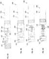
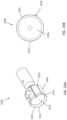
- FIGS. 1A-3show an example of an atherectomy catheter 100 including a nosecone that deflects to expose a cutter.
- the atherectomy catheter 100can include a catheter body 101 having an outer shaft 111, a cutter 103 at a distal end of the catheter body 101, and a nosecone 105 at a distal end of the catheter body 101.
- the nosecone 105can further include a cutting window 107 through which the cutting edge 112 of the cutter 103 can be exposed.
- the nosecone 105can be configured to deflect away from the longitudinal axis of the catheter body 101 about a hinge point 1109, as described further below. This deflection can expose the cutter 103 through the cutting window 107 and/or radially push the cutter 103 into a wall of the vessel in which the atherectomy catheter is inserted.
- the cutter 103can be positioned between the catheter body 101 and the nosecone 105 via a bushing 155.
- the cutter 103can be an annular cutter with a sharp distal edge 112.
- the cutter 103is attached to a drive shaft 113 configured to rotate the cutter 103.
- the atherectomy catheter 100can include an imaging element 192, such as an OCT imaging element, within the cutter 103 and proximal to the cutting edge 112 of the cutter 103.
- the imaging element 192can include an optical fiber 197 that runs substantially on-axis through the center of the elongate body, such as through the driveshaft 113, to transmit the OCT signal. Further, the optical fiber 197 can run straight throughout the catheter body 101 without bending.
- the optical fiber 197can be attached at the distal end to the cutter 103, such as in a slot 177 in the cutter 103.
- the slotcan have a length that extends at least to the center of the cutter 103 so as to allow the optical fiber 197 to remain on-axis without a bend through the length of the catheter body 101 and the cutter 103. Aside from the attachment to the cutter 103, the optical fiber 197 can be otherwise be free to float within the catheter body or drive shaft 113. In other embodiments, the optical fiber 197 can be attached to the drive shaft 113 along the length thereof.
- the imaging element 192can include a reflective element 199, such as a mirror.
- the reflective element 199can be located within the slot 177 in the cutter 103 to radially direct light from the optical fiber 197 into the adjacent tissue (through the cutter window 107).
- the reflective element 199can be oriented at an angle relative to the axis of the optical fiber 197, such as at a 35-55 degree angle, e.g. 45 degree angle, to reflect light into the tissue.
- the distal end of the optical fiber 197can be located less than 3mm from the cutting edge, such as less than 1mm from the cutting edge, such as less than 0.5mm.
- the outer shaft 111can be configured to be turned, such as turned manually, to position the cutter window 107, cutter 103, and/or the imaging element 192 toward the desired location.
- the driveshaft 113can then be rotated to rotate the cutter 103 and the imaging elements 197. Rotation of the cutter can provide cutting due to the rotational motion of the cutting edge and provide the rotation necessary to image the vessel wall via the imaging element.
- the drive shaftcan be rotated at up to 2,000 rpm, such as approximately 1,000 rpm in a single direction, though rotation in both directions or at higher or lower speeds is possible.
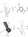
- the drive shaft 113can further be configured to translate axially in the proximal and/or distal directions. Such axial movement of the drive shaft 113 can open and/or close the nosecone 105 about the hinge point 1109 (e.g., a pin in the bushing 155) to expose or conceal and protect the cutting edge 112 of the cutter 103.
- the bushing 155can include an inner flange 170 that extends radially inwards. The inner flange 170 can be positioned distal to the hinge point 1109.
- the bushing 155can further include sloped outer distal surface 143 that angles radially inward from the distal end to the proximal end.
- the cutter 103can include a proximal edge 166 and a tapered neck 168 that gets narrower from the driveshaft 113 to the head of the cutter 103. The interaction of these various elements can open and close the nosecone 105.
- proximal retraction of the drive shaft 113opens the nosecone 105 to expose the cutter.
- the proximal edge 166 of the cutter 103is forced against the sloped distal surface 143 of the bushing 155. Because the sloped distal surface 143 angles radially inward from the distal end to the proximal end, the cutter 103 forces the bushing 155, and thus the nosecone 105, to deflect away from the longitudinal axis of the catheter body 101, thereby opening the nosecone 105 (see the transition from FIGS. 2A to 2B and 2B to 2C ).
- the cutting window 107can have an opening that is larger than the diameter of the cutter 103 and cutting edge 112 to allow the cutter 103 to protrude out of the nosecone 105 when the nosecone 105 is deflected.
- distal movement of the drive shaft 113closes the nosecone 105.
- the tapered neck 168 of the cutter 103will correspondingly move distally.
- the distal movement of the tapered neck 168causes the inner flange 170 of the bushing 155 to drag along the widening edges of the tapered neck 168, thereby lifting the bushing 155, and correspondingly, closing the nosecone 105 (see the transition from FIGS. 2C to 2B and 2B to 2A ). Because the hinge point is proximal to the inner flange 170, a mechanical advantage is achieved that allows for complete closing of the nosecone.
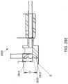
- FIGS. 7A-7Dshow close-ups of the bushing 155.
- the bushing 155can include two intersecting channels 721, 723 configured to hold the necked portion 168 of the imaging subassembly therein when the nosecone is in the open configuration (channel 723) and the closed configuration (channel 721).
- Channel 721extends through a long distal to proximal axis of the bushing 155 while channel 723 extends at an angle relative to channel 721 and overlaps therewith.
- the bushing 155can further include a hinge channel 745 formed through a top peripheral region of the bushing 155 so as to provide the pivot point 1109. The hinge channel 745 can be transverse to the channel 721.
- a catheter 200(having similar features to catheter 100 except the opening and closing mechanisms) can include a cam slot 228 in the bushing 155 that angles toward the cutting window 107 from the proximal end to the distal end.
- a cam member 290can be attached to the cutter 103 and configured to extend through the cam slot 228.
- the cam member 290will move within the angled cam slot 180.
- the movement of the cam member 290 within the angled cam slot 180causes the bushing 155, and thus the nosecone 150, to drop down.
- the driveshaft 113can be pulled proximally, thereby causing the cam member 290 to ride within the cam slot 228 and pull the bushing 155 back into line with the elongate body 101.
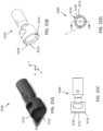
- FIGS. 11A-11B and 12A-12BAnother mechanism of opening and closing a nosecone of an atherectomy catheter 400a, b is shown in FIGS. 11A-11B and 12A-12B .
- the catheter 400a, bcan have the same features as catheter 100 except that the outer distal surface 443a,b of the bushing 455a,b can be either normal to the longitudinal axis of the device (such that the angle ⁇ is 90 degrees), as shown in FIG. 11B or slanted radially outward from the distal end to the proximal end (such that the angle ⁇ is greater than 90 degrees and the angle with the longitudinal axis is less than 90 degrees), as shown in FIG. 12B .
- FIGS. 11A-11B and 12A-12BAnother mechanism of opening and closing a nosecone of an atherectomy catheter 400a, b is shown in FIGS. 11A-11B and 12A-12B .
- the catheter 400a, bcan have the same features as catheter 100 except that the outer distal
- an angled spaceis provided between the proximal edge 166 of the cutter and the distal surface 443b such that the only point of contact is an inner radial edge 444 of the bushing 455b.
- the catheter 400awill open and close similarly to as described with respect to catheter 100.
- the catheter 500bwill open slightly differently in that only the inner-most radial edge 444 will interact with the proximal edge 166 of the cutter 103, as opposed to the entire surface 443, when the driveshaft 113 is pulled proximally.
- Such a configurationcan advantageously reduce friction while opening the nosecone 105.
- the proximal edge 166can be angled with respect to a longitudinal axis of the catheter; in such cases, the opposing surface 443 of the bushing 455 can be either parallel to or angled (acute or obtuse) with respect to the proximal edge 166.
- the atherectomy catheter 100can further include a mechanism for packing tissue into the nosecone, such as by moving the drive shaft axially.
- movement of the drive shaft 113distally closes the nosecone 105.
- Moving the drive shaft 113further distally will move the cutter 103 into a passive position (i.e., against a distal edge of the window 107) where the cutter 103 can be protected by the edge of the window 107 to avoid undesired cutting of the vessel during use.
- Moving the drive shaft 113further distally will move the cutter 103 into the nosecone 105, thus packing tissue with a distal face of the cutter 103, as shown in FIG. 3 .
- the cutter 103can move more than 1.27 cm (0.5 inches), such as more than 2.54 cm (1 inch) or more than 5.08 cm (2 inches) into the nosecone 105 to pack the tissue.
- the nosecone 105is formed of a material that is OCT translucent (e.g., non-metallic) so that panoramic OCT images can be taken therethrough.
- a bushing 1655can include all of the features of the bushings described above, but can additionally include jet channels 1785a,b cut into the inner circumference thereof and extending from the proximal end to the distal end.
- the jet channels 1785a,bcan connect a fluid line within the elongate body 101 to the nosecone 105. Fluid flowing through the jet channels 1785a, b can increase speed and thus provide enough force to pack cut material into the nosecone and clear the imaging region within the nosecone. Further, the jet channels can create a venturi effect at the distal end of the bushing 1655, which can suck material into the nosecone and/or away from the imaging/cutting head and/or the distal end region of the elongate body.
- the atherectomy catheter 100(or 200 or 400) includes a guidewire lumen in the nosecone 105, such as a monorail, for use in guiding the catheter.
- the guidewire lumencan be used as a marker during imaging.
- Atherectomy catheters 100, 200, or 400there can be one or more small imaging windows 207, 307 in the nosecone 105 opposite to the cutting window 107, as shown in FIGS. 1A and 2A-2C .
- These additional imaging windows 207can provide more of a 180 degree view during imaging.
- one set of windows 207can be more proximal and configured to be axially aligned with the cutter 103 and the imaging element 192 when the nosecone is opened while the other set of windows 307 can be more distal and configured to be axially aligned with the cutter 103 and the imaging element 192 when the nosecone is closed and the cutter 103 is in the passive position.
- the imaging windows 307, 207have different shapes from one another to further help identify cutter position in the resulting OCT images.
- the OCT image catheter with the devicewill vary depending upon the placement of the imaging device in the three different configurations (nosecone open, nosecone closed with cutter in cutting position, nosecone closed with cutter in packing position). Accordingly, a user can identify, simply by looking at the imaging display, whether the nosecone 105 is displaced and whether the cutter 103 is in the cutting or packing position.
- FIG. 8Ashows a panoramic image 800 of a surrounding vessel when the cutter 103 (and, correspondingly, the imaging sensor) is in the cutting position, as shown in FIG. 8B .
- the wall of the nosecone 105is displayed as the circular feature 808 in the image 800.
- the nosecone 105is made of a clear material, the vessel tissue 806 can be imaged even through the nosecone 105.
- a 180 degree view of the tissue 806can thus be obtained.
- the circular artifact 803 in the image(and here, the radial line 801) correspond to a guidewire and/or guidewire channel running alongside the nosecone 105.
- FIG. 9Ashows a panoramic image 900 of a surrounding vessel when the cutter 103 is in the passive position and the nosecone 105 is closed, as shown in FIG. 9B .
- a 180 degree view of the vessel tissue 906is shown on the right side of the image (taken through window 107) while the closed nosecone 909 is shown on the left side of the image (the lines 909a,b correspond to the bushing wall).
- the space 913 between the lines 909a,b through which tissue 906 can be seen on the left side of the imageis taken through the additional window 307 in the bushing.
- the distance between the arrows in image 900indicates that the distal tip is "closed" (and close therefore close to the midline of the catheter).
- FIG. 10Ashows a panoramic image 1000 of a surrounding vessel when the cutter 103 is in the cutting position and the nosecone 105 is open, as shown in FIG. 10B .
- the vessel tissue 1006(taken through window 107) is shown on the right side of the image while the closed nosecone 1009 is shown on the left side of the image (the lines 1009a,b correspond to the bushing wall).
- the space 1013 between the lines 1009a,b through which tissue 1006 can be seenis taken through the window 207.
- a comparison of the relative distance between the arrows in FIGS. 9A and 10Ashows an increased distance between the catheter body and the nosecone, thereby suggesting to the operator that the nosecone 105 is in an open position.
- the image resulting from the window 207/307will look different due to the angle change between the windows 207/307 and the imaging element 297 and/or the different shape of the windows 207/307.
- the atherectomy catheter 100(or 200 or 400) includes a flush port close to the cutter 103.
- the flush portcan be used to deliver flushing fluid to the region of imaging, thereby improving image quality.
- the flushingcan be activated through a mechanism on the handle of the device.
- the fluidcan, for example, be flushed in the annular space between the catheter body 101 and the driveshaft 113. Further, in embodiments with jet channels in the bushing, the annular space can connect to the jet channels to provide fluid thereto.
- the atherectomy catheters 100, 200, 400can further include two or more balloons configured to help urge the cutter 103 into the tissue.
- the first balloon 333can be the distal-most balloon.
- the first balloon 333can be positioned proximate to the hinge point 1109 and opposite to the cutting window 1107.
- the balloon 333can urge the cutter 103 against the tissue by deflecting the cutter 103 up and into the tissue.
- a second balloon 335, proximal to the distal balloon 333,can be on the same side of the catheter 100 as the cutting window 107 and can further help drive the cutter 103 into the tissue by.
- the second balloon 335can be annular.
- the second balloon 335can help occlude the vessel.
- a third balloon 337can be used for occlusion.
- the balloons 333, 335, 337can further include tapered edges on the proximal and distal edges that allow the balloon to slide along the vessel and/or fit through tortuous regions.
- the atherectomy catheters 100, 200, 400can include a single balloon configured to both urge the cutter 103 into the tissue and occlude blood flow to improve imaging.
- the balloon 1733can have a crescent shape, i.e., can be wrapped around the catheter 100 so as to cover the entire circumference of the catheter 100 except where the cutter 103 is exposed.
- the balloonincludes wide necks at both ends that are then wrapped around the nosecone 105 and elongate body 101 such that they cover at least half of the circumferential surface.
- FIG. 16Ashows the wrapped balloon edges 1735 while FIG. 16B shows the wide necks 1737 fused at both ends.
- FIG. 16Cshows an inflation port 1739 contained inside the balloon 1733 as well as a guidewire lumen 1741 that spans the length of the balloon 1733.
- the balloon 1733can be used to open or close the nosecone without requiring proximal or distal movement of the driveshaft.
- a handle 300can be used to control the rotation or translation of the driveshaft for the catheter 100, 200, or 400.
- the handle 300can advantageously allow the optical fiber to move distally and proximally with the cutter as it is driven without requiring the fiber to move at a proximal location, e.g., without requiring movement of the optical fiber assembly within the drive assembly.
- the handle 300can be designed to completely account for movement of the drive shaft.
- An exemplary driveshaft management system 555is shown in FIG. 5 .
- the driveshaft management system 555allows the user to position the driveshaft distally or proximally as the driveshaft is simultaneously spinning at a high speed.
- the driveshaftcan be configured such that it is fully tensioned before the driveshaft management system 555 is positioned at its most proximal position. That is, the driveshaft management system 555 can include a driveshaft tensioning spring 556.
- the spring 556can be configured such that, as the user positions the slideable user ring 557 (or button) proximally, the driveshaft is fully tensioned and the driveshaft management system 555 is moved proximally, causing the spring 556 to compress and apply a controlled tensile load on the driveshaft.
- This fiber management system 555advantageously enhances performance of the catheter by tensioning the driveshaft with a pre-determined load to properly position the cutting and imaging component against the bushing at the distal end of the catheter, improving cutting and imaging of the catheter.
- the driveshaft management system 555can transmit torque originating from a drive assembly, as described further below. Connection to the drive assembly can be made at the optical connector 559. Torque can thus be transmitted from the optical connector 559, through the fiber cradle 551, to the drive key 560, through the driveshaft management system 555, and then directly to the catheter driveshaft, all of which can rotate in conjunction.
- the fiber cradle 551can include a set of components (i.e., a pair of pieces to make the whole fiber cradle) that houses the proximal end of the optical fiber and transmits torque within the driveshaft system.
- the fiber cradle componentscan be thin-walled by design, thereby creating a hollow space inside.
- the optical fibercan be inserted or withdrawn as the device driveshaft is positioned proximally or distally.
- the fiberis able to coil within the internal space of the fiber cradle 551 while maintaining imaging throughout its length to the distal tip.
- the coiled section of fiberis able to straighten while maintaining imaging throughout its length to the distal tip.
- the handle 300can further include a balloon inflation chamber 552 configured to connect to a balloon inflation lumen (e.g., for use with a balloon on the catheter as described above) on one side and to balloon inflation tubing 553 and/or a port 554 on the other side. Because the inflation fluid transfers to the balloon through the balloon inflation chamber 552, the outer shaft 111 can advantageously rotate (e.g., by rotating the knob 558) independently of the balloon inflation chamber 552, allowing the tubing 553 and/or port 554 to remain stationary during rotation of the outer shaft 111.
- a balloon inflation lumene.g., for use with a balloon on the catheter as described above
- the handle 300can further include a catheter flush chamber 663 and catheter flush tubing 664 and/or flush port 665 to provide flushing through the catheter, as described above.
- any of the atherectomy catheters described abovecan be used with a cutter having a serrated distal edge designed to remove calcified and hard fibrous disease in an artery.
- the calcified and hard fibrous diseasecan be difficult to remove due to its increased hardness compared to plaque.
- a standard cuttermay have no problem debulking the majority of arterial plaque, in certain instances, the plaque encountered by an atherectomy catheter may be harder and/or of a greater volume than what is typically encountered. This may be due to plaque having a larger percentage of calcium, fibrin, and other cellular waste relative to the percentage of fat and cholesterol.
- a serrated or scalloped cutter with a serrated cutting edgecan facilitate cutting and breaking away calcified and fibrous disease.
- the serrated edgecan advantageously initiate the cut into the calcium by utilizing a large force over a small area, thereby providing the greatest cut efficiency to engage and cut the hardened disease.
- FIGS. 17A-17Bshow an exemplary atherctomy catheter 1700 with a serrated cutter 1703.
- the catheter 1700includes a catheter body 1701 and a nosecone 1705 hinged to the catheter body 1701 at an off-axis hinge point 1709.
- the nosecone 1709can be configured to collect tissue therein.
- the cutter 1703can be moved distally to pack tissue into the nosecone.
- the serrated cutting edge 1710 of the cutter 1703can be pushed into the tissue.
- a balloon 1733when inflated, can also aid in moving the cutting edge 1710 towards the tissue.
- FIGS. 18A-31Eillustrate various serrated cutters that can be used, for example, with atherectomy catheter 1700, to break down calcified and hard fibrous disease in the artery.
- the serrated cutting edgecan spin at a high speed with various serrated geometries configured to engage hard calcified and fibrous disease in the diseased arteries.
- FIGS. 18A-18Eshow a first variation of a serrated cutter 1800 designed for removing calcified plaque.
- the serrated cutter 1800has a proximal end 1802 and a distal end 1804.
- the proximal end 1802is attachable to drive shaft of an atherectomy catheter.
- the distal end 1804includes a cutting edge 1810 along the circumference of the serrated cutter 1800 that includes teeth 1812.
- the teeth 1812create saw-like serrations along the edge 1810 that are configured to cut into calcified tissue.
- FIG. 18Eshows the cross-sectional side view of the cutter 1800 attached to a driveshaft 1813.
- the serrated cutter 1800also includes a symmetric and concave or recessed bowl 1814 extending radially inwards from the cutting edge 1810 to the central axis of the cutter 1800. Further contained within the bowl region is an asymmetric cavity 1816 (i.e., extending off of a central axis of the cutter 1800). The asymmetric cavity 1816 covers between 1/3 and 1/2 of the surface area of the bowl region 1814 of cutter 1800. The asymmetric cavity 1816, as shown in FIG. 18D , includes three regions that further aid with breaking up of the harder forms of plaque.
- seams 1815delineate the three regions of the asymmetric cavity 1816 may protrude slightly above the surface of the asymmetric cavity 1816 walls, where the seams 1815 may be sharp or may include grabbing features that further aid with gripping onto and breaking apart calcified plaque deposits. It is also conceivable that the asymmetric cavity includes greater or less than three regions. As the cutter 1800 is rotated, the asymmetric cavity 1816 advantageously breaks up the calcium plaque within the bowl 1814 as the off-axis sidewalls and/or seams hit the rigid pieces within the bowl 1814, advantageously avoiding having the calcified plaque fold back onto itself (which can cause stalling of the cutter).
- Each tooth 1812 of the cutter 1800borders a grinding segment 1818.
- the grinding segments 1818are depressions or scoops in the bowl 1814 that have a greater curvature than the bowl 1814.
- the grinding segments 1818have a concave curvature at the distal end 1804 of the cutter 1800 (as seen in FIGS. 18C and 18E ).
- the grinding segments 1818 of the serrated cutter 1800are largely semi-circular in shape and disposed equidistantly about the perimeter of cutter 1800.
- the grinding segments 1818can have sharp edges or points therearound that are configured to grind, sever, and/or grab onto the calcified plaque by applying more pinpointed force to the calcified plaque encountered while the cutter is rotating.
- the grinding segments 1818 disposed about the circumference of cutter 1800may be otherwise shaped (e.g. square or rectangular cut outs, triangular cut outs, symmetric, asymmetric, and so forth). Further, the grinding segments 1818 can be either equidistantly disposed about the cutter perimeter or can be more unevenly or non-uniformly disposed about the cutter perimeter.
- FIGS. 19A-19Eshows drawing of a second variation of a serrated cutter 1900 designed for removing calcified plaque deposits.
- the serrated cutter 1900 shown in FIGS. 19A-19Epossess many of the same features as the cutter 1800 shown in FIGS. 18A-18D , such as a serrated cutting edge 1910 having teeth 1912 and half-circular grinding segment 1918s disposed evenly along the circumference of the cutting edge 1910. Similar to the design shown in FIGS. 18A-18E , the grinding segments 1918 can be depressions within the bowl 1914 that are disposed along the perimeter of the cutter 1910. The grinding segments 1918 can aid with grabbing and grinding into calcified plaque as the cutter rotates and are able to impart targeted force on the calcified plaque encountered and more easily break off the harder plaque formations.
- the bowl 1914is symmetric and recessed in essentially in the shape of a half sphere for accommodating larger plaque formations.
- the bowl region 1914may also include additional features that can further aid with grabbing and breaking apart calcified plaque as the cutter rotates. Additional features may include protrusions, or cavities about its sidewalls that are either symmetrically or asymmetrically distributed along the wall. The protrusions may have a sharp edge or point while the cavity may have a sharp edge, where these features aid with gaining purchase of the calcified plaque during the procedure. There may also be features at the base of the bowl that aid with gripping and purchase while the serrated cutter is rotating.
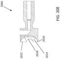
- FIGS. 20A-20EAnother variation of a serrated cutter 2000 for easier debulking of calcified plaque is shown in FIGS. 20A-20E .
- the serrated cutter 2000includes a bowl region 2014 having a serrated cutting edge 2010 disposed along its perimeter.
- the cutting edge 2010includes a plurality of teeth 2012 extending therearound with a plurality of grinding segments 2018 therebetween.
- the grinding segments 2018can form a deeper scooped portion along the serrated edge 2010.
- the grinding segments 1218can extend radially inwards towards and past the center of the bowl 2014 in an off-axis or spiraled manner. While the scooped grinding segments 2018 are shown in FIG.
- the scooped regions 2018creates rotational asymmetry within the bowl region 2014 that allows the walls of the grinding segments 2018 to grab onto the plaque and scoop the plaque out and break the plaque up.
- the combination of the teeth 2012 and the off-axis scoop cuts of the grinding segments 2018provide enhanced cutting and grinding of calcified plaque as the cutter 2000 rotates.
- the teeth 2012 and/or grinding segments 2018may further include edges or seams 2016 that are raised with respect to the surface of the scooped regions 2018 to further aid with gripping the calcified plaque during use.
- the bowl 2014 and/or the off-axis scooped regionsmay also include other gripping texture or features that are able to further enhance the purchase of the cutter on plaque deposits encountered during use of the cutter.
- FIGS. 21A-21Eshow another variation of a serrated cutter 2100 that is well-suited for debulking calcified plaque.
- Serrated cutter 2100also includes a serrated cutting edge 2110 along the circumference of cutter 2100.
- Serrated cutter 2100also includes a bowl region 2114.
- Cutter 2100further includes a series of teeth 2112 and a series of scooped out grinding regions 2118 that each begin at the cutting edge 2114 and extend inward towards the center of the bowl region 2114.
- the edge of the scooped out region 2118correspond to concave portions along the perimeter of the cutting edge 2110.
- the teeth 2112 and the scooped grinding segments 2118aid greatly with gaining purchase of the calcified regions and providing targeted force onto the calcified plaque.
- the series of scooped grinding segments 2118are arranged in a helical patter within bowl region 2114.
- the helical cutting pattern 2118can advantageous help grab onto plaque and cut the plaque when the cutter is rotating.
- Cutter 2100may also include additional features 2116 within the bowl 2114 that increase the cutter's gripping ability while in use.
- FIGS. 22A and 22Bshow a cutter 2200 having no serration along the outer circumference.
- the cutter 2200similar to the other cutters already described, includes a bowl region 2214.
- the cutter 2200has a cutting edge 2210 along its outer perimeter.
- the cutting edge 2210is smooth and continuous.
- cutter 2200has a series of breaker pockets or grinding segments 2218 distributed along an inner circumference of the bowl region 2214.
- Each grinding segment 2218includes a cavity (having a greater curvature than the bowl 2214) for aiding in gripping onto hardened plaque and serve to break up and debulk calcified plaque encountered.
- the grinding segments 2218can be in the shape of a circle or an oval.
- the intersection between the grinding segments 2218 and the areas of the bowl regions 2214may possess sharpened edges that further aid with gripping and breaking up of hardened plaque. As the cutter 2200 rotates, the grinding segments 2218 can aid with further crushing of the plaque formations and sending these broken down plaque into the nosecone region. While the grinding segments shown in FIGS. 22A and 22B are symmetric and evenly distributed within the bowl region, in some arrangements, the breaker pockets may be asymmetric in shape and may not all be of the same size.
- cutter 2300includes features that may be able to alleviate some or all of the hydraulic pressure. Like many of the cutters previously discussed, the cutter 2300 includes a bowl region 2314 and a serrated cutting edge 2310 disposed therearound. Here, the teeth 2312 are separated by V-shaped grooves 2323 distributed around the perimeter of the bowl region 2314.
- V-shaped grooves 2323 of cutter 2300may extend along an outer wall 2320 of cutter 2300 such that where the V-shaped grooves 2318 occur, corresponding V-shaped channels 2319 extend from the V-shaped groove 2323 along the entire length of cutter 2300's outer wall.
- the V-shaped channels 2319 spaced around the outer wall of cutter 2300serve to relieve any hydraulic pressure that may be generated in the nose cone when the cutter is slid forward deeper into the nosecone and subsequently when the cutter is drawn back during rotation of the cutter.
- the cutter 2400includes a bowl region 2414 and a serrated cutting edge 2410 disposed along the perimeter of the bowl region 2414.
- the serrated cutting edge 2410includes a plurality of teeth 2412 separated by shallow cutouts 2423 in the cutting edge 2410.
- the shallow cutouts 2423extend along an outer wall 2420 of the cutter 2400 to form a rounded channels 2419 that are disposed on the outer wall 2420 of the cutter 2400.
- the rounded channels 2419similar to the V-shaped channels 2319 described earlier, can serve to relieve hydraulic pressure that may build up while the rotating cutter is pushed into the nosecone of the catheter.
- FIGS. 25A and 25Bshows a cutter 2500, another variation of cutter designs that include grooves along the outer wall of the cutter.
- the cutter 2500includes a bowl region 2514 and a serrated cutting edge 2510 disposed along the perimeter of the bowl region 2514.
- the cutting edge 2510is formed by teeth 2510 separated by v-shaped recesses 2512.
- the v-shaped recesses 2523are asymmetric such that the channels 2519 that are formed from the asymmetric recessed regions 2512 and that extend along an outer wall 2520 of the cutter 2500 are also asymmetric in nature.
- An advantage of having asymmetric grooves disposed along the outer wall of the cutteris that there is less likelihood that the groove edges from catching on the inner diameter of the nosecone as the cutter is rotating.
- FIGS. 26A and 26BAnother variation of a cutter 2600 is shown in FIGS. 26A and 26B .
- the cutter 2600includes a bowl region 2614 and a cutting edge 2610 disposed along the perimeter of the bowl region 2614.
- the cutting edge 2610has a smooth cutting surface about the outer perimeter of the bowl region 2614.
- the cutter 2600further includes angled channels 2619 disposed around the outer wall 2620 of the cutter 2600.
- the angled channels 2619preserves the smooth cutting edge 2610 by originating on the outer wall 2620 of the cutter 2600 just below the cutting edge 2610 and extending away from the smooth cutting edge 2610.
- the cutter 2600may be used in scenarios where the plaque encountered are not of the hardened and calcified variety and where a smooth cutting edge can successfully debulk the plaque encountered.
- the grooves arranged around the outer wall 2620are able to minimize the buildup of hydraulic pressure when the cutter is pushed and subsequently pulled back from the catheter nosecone.
- FIGS. 27A-27Eillustrate an exemplary embodiment of a serrated cutter 2700 having a serrated annular cutting edge 2710, a recessed bowl 2714, and a plurality of grinding segments 2718.
- the cutter 2700includes the recessed bowl 2714 extending radially inwards from the annular cutting edge 2710 to a center of the cutter 2700.
- the recessed bowl 2714can extend radially inwards from the cutting edge 2710 with a converge angle.
- the converge angle of the recessed bowlcan be 90 degrees, as shown in FIG. 27E .
- the cutter 2700can further include a plurality of grinding segments 2718 or dimples within the bowl 2714 and extending radially inwardly from the cutting edge 2710.
- the plurality of segments 2718can each have a substantially circular or ovoid shape. In some other embodiments, the plurality of segments 2718 may be otherwise shaped. Further, each of the plurality of segments 2718 can have a curvature that less than the curvature of the bowl 2714. As shown in FIGS. 27A-27D , each of the plurality of grinding segments 2718 can be a flat facet (i.e., such that the curvature is zero and the radius of curvature is infinite).
- the plurality of grinding segments 2718can advantageously break the uniformity of the recessed bowl 271, thus facilitating breaking hard substances such as calcium.
- the number of segmentscan be 2, 3, 4, 5, 6, 8, 12 or any number therebetween.
- the cutter 2700can have six grinding segments 2718 as shown in FIGS. 27A-27E .
- the plurality of grinding segments 2718can be either equidistantly disposed about the cutter perimeter or can be more unevenly or non-uniformly disposed about the cutter perimeter.
- the plurality of segments 2718can be disposed symmetrically or unsymmetrically around the circumference of the cutting edge 2710.
- each of the plurality of segments 2718forms a convex tooth 2712 of the serrated annular cutting edge 2710.
- the convex teeth 2712are a portion of a circular shape or elliptical shape or other convex shape.
- the convex shaped teeth 2712can be advantageous because there no sharp points are formed along a distal-most circumference of the cutting edge 2710. Since there is a constant force being applied along the arc from cutting tissues, the convex shaped portions are gentle in contact with tissue and have a long cutting length, thus engaging again tissue for a long time.
- the plurality of convex teeth 2712can be configured to grind and grab onto the calcified plaque by applying pinpointed force to the calcified plaque encountered while the cutter is rotating.
- the serrated annular cutting edge 2710can angled radially inward relative an outer-most circumference of the cutter 2710 (and/or relative to the elongate body of the catheter to which it is attached).
- the outer side wall of the cutter edge 2710 on the distal tip 2704can have an angle ⁇ relative to a sidewall of the outermost circumference of the cutter 2700 (or of the attached catheter body) along a longitudinal direction.
- the angle ⁇is advantageous such that the cutting edge 2710 does not cut through the nosecone itself.
- the angle ⁇can be between 2 to 12 degrees in some embodiments. For example, the angle ⁇ can be 5 degrees.
- the distal tip 2704 of the serrated annular cutting edge 2710can extend radially inward relative an outer diameter of the elongate body by 2 degrees to 12 degrees.
- the serrated annular cutting edge 2710can be angled radially and converged to a center axis of the cutter 2700 with a converge angle between 4 degrees and 20 degrees.
- the converge anglecan be 10 degrees in some embodiments as shown in FIG. 27E .
- FIG. 28A-28Eillustrate another serrated cutter 2800 having a serrated annular cutting edge 2810, a recessed bowl 2814, and a plurality of grinding segments 2818.
- the serrated annular cutting edge 2810can have a plurality of teeth 2812.
- each of the plurality of segments 2818can form concave edges between the teeth 2812 of the serrated annular cutting edge 2810.
- the curvature of the grinding segments 1818can be greater than the curvature of the bowl 2814, thereby forming depressions or cavities in the bowl 2814.
- the number of segmentscan be 2, 3, 4, 5, 6, 8, 12 or any numbers therebetween.
- the cutter 2800can have seven recessed grinding segments 2818 as shown in FIGS.
- the plurality of grinding segments 2818can be either equidistantly disposed about the cutter perimeter, as shown, or can be more unevenly or non-uniformly disposed about the cutter perimeter.
- the plurality of segments 2818can be disposed symmetrically, as shown, or unsymmetrically around the circumference of the cutting edge 2810.
- the serrated annular cutting edge 2810can be angled radially inward relative an outer diameter of the cutter 2800 (and/or the elongate body of the catheter).
- the outer side wall of the cutter edge 2810forms an angle ⁇ relative to a sidewall of the elongate body of the catheter 2800 along a longitudinal direction.
- the angle ⁇can be between 2 to 12 degrees in some arrangements.
- the angle ⁇can be 5 degrees.
- the distal tip of the serrated annular cutting edge 2810can extend radially inward relative an outer diameter of the elongate body by 2 degrees to 12 degrees.
- the angle ⁇advantageously ensures that the cutting edge 2810 does not cut through the distal tip or nosecone of the catheter.
- the serrated annular cutting edge 2810can be angled radially and converged to a center axis of the cutter 2800 with a converge angle between 4 degrees and 20 degrees.
- the converge anglecan be 10 degrees as shown in FIG. 28E .
- FIGS. 29A-29Eillustrate a cutter 2900 including a serrated annular cutting edge 2910 with teeth 2912 and a recessed bowl 2914.
- the atherectomy cutter 2900can be similar to the cutter 2800 except that the cutter can include five grinding segments 2918 rather than seven. Further, each of the segments 2918 can be longer, e.g., extend a greater distance along the circumference of the cutting edge 2910, than in cutter 2800.
- FIGS. 30A-30Eillustrate a cutter 3000 including a serrated annular cutting edge 3010 with teeth 3012 and a recessed bowl 3014.
- the cutter 3000can be similar to cutters 2800 and 2900 except that the cutter can include ten grinding segments 3018.
- the grinding segments 3018can form a substantially half-circle shape.
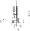
- FIGS. 31A-31Eillustrate a cutter 3100.
- the cutter 3100can be similar to cutter 3000 except that the grinding segments 3118 can be further closer to one another, thereby making the teeth 3112 shorter.
- the cutting edge of each tooth 3112 of cutter 3100can be approximately 0.1-0.3, such as approximately 0.25, of the length of cutting edge of each grinding segment 3118.
- the cutting edge of each tooth 3012can be approximately 0.4-0.6, such as 0.5 of the length of the cutting edge of each grinding segment 3018.
- the cutter 3100can also be smaller in size overall (e.g., be configured to sit within a 7 French catheter 1 French is equivalent to 0.33 mm) than the cutter 3000 (which can be configured, for example, to sit within an 8 French catheter).
- the cutters described hereincan be used, for example, for above the knee atherectomy procedures.
- the cuttercan be designed to fit in an 8 French catheter and thus can have a diameter, for example, of between 1.78 mm and 22.86 mm (0.07 inches and 0.9 inches), such as approximately 1.96 mm (0.077 inches).
- the cutters described hereincan also be used, for example, for below the knee atherectomy procedures.
- the cuttercan be designed to fit in a 7 French catheter and can have a diameter, for example, of between 1.27 mm and 1.78 mm (0.05 inches and 0.07 inches), such as approximately 1.65 mm (0.065 inches).
- the recessed bowl in the cutters described hereincan advantageously help collect and push cut tissue or plaque into the collection chamber in the nosecone of the atherectomy device.
- the cutters describedcan be useful for gripping on to and breaking apart calcified plaque deposits found within the arteries as well as softer forms of plaque that may be encountered. Because calcified plaque is much harder than its softer plaque counterparts, repeated use of the cutter for breakoff and clearing calcified plaque can easily lead to dull cutting edges that are less proficient at grabbing onto and breaking off calcified plaque during subsequent use.
- the cutting edge or even the entire cutter region, including the cutting edge and the bowlmay be coated with or dipped in a hardening material. Suitable hardening coatings may include carbon composites such as tungsten carbide, graphene, and so forth. While the cutters described herein are shown with specific features, it is conceivable that different features from the different cutters described may be combined to form cutters having feature combinations that have not been specifically described herein.
- the serrated cutters described hereincan be configured to be interchangeable with one another and/or with non-serrated cutter so as to allow the operator to vary the aggressiveness of the cutter during use.
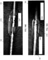
- FIG. 13Ashows the removal of a single, long strip of material cut from the tissue by an atherectomy catheter as described herein.
- FIGS. 13B and 13Cshow the length of tissue (weighting 70.4 mg) removed.
- the atherectomy catheters described hereinmay additionally include any of the features described in the following co-pending applications: PCT Application No. PCT/US2013/031901, entitled “ATHERECTOMY CATHERES WITH IMAGING,” and filed March 15, 2013 , and PCT Application No. PCT/US2013/032494, entitled “BALLOON ATHERECTOMY CATHERS WITH IMAGING” and filed March 15, 2013 , and PCT Application No. PCT/US17/22780, entitled “ATHERECTOMY CATHETERS AND OCCLUSION CROSSING DEVICES” and filed March 16, 2017 .
- the catheters described hereincan be driven using a drive assembly.
- Exemplary drive assembliesare described in co-pending Patent Applications: PCT Application No. PCT/US13/32089, entitled “ATHERECTOMY CATHETER DRIVE ASSEMBLIES,” filed March 15, 2013 , and U.S. Patent Application No. 13/654,357, titled “ATHERECTOMY CATHETERS AND NON-CONTACT ACTUATION MECHANISM FOR CATHETERS,” filed October 17, 2012 .
- support armsfor maintaining and positioning a medical device component, such as a controller or drive assembly of an atherectomy catheter, during related medical procedures.
- the support armis able to attach easily to any rail in close proximity to the procedure table and to take multiple positions for providing convenient access to a catheter (e.g., atherectomy catheter) control unit.
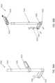
- FIGS. 32A-32CAn exemplary support arm assembly 9100 is shown in FIGS. 32A-32C .
- the support arm assembly 9100can include a clamp 9110, a support arm 9130 and a device mount 9150.
- the assembly 9100can also include a cable retainer 9170.
- the support arm 9130has two ends. The clamp 9110 couples to one end of the support arm 9130, and the device mount 9150 couples to the other end.
- the support arm 9130may be releaseably attached to clamp 9110. Support arm 9130 may swivel up to 9360 degrees with respect to clamp 9110. This allows the support arm 9130 to be easily positioned anywhere along the length of an operating or procedure table. The support arm 9130 may also be adjusted so that it can reach the width of any operating or procedure table. In use, the free end of the support arm 9130 is coupled to the device mount 9150. The free end of the support arm 9130 can allow for rotational freedom of the coupled device mount 9150 such that the device component being held by the device mount 9150 may be arranged in the most optimal position during a procedure.
- the support arm 9130can include two segments 9134 and 9139 joined by a segment joint 9135. While FIG. 32B shows segments 9134 and 9139 as being cuboid in shape, the segments can be any reasonable geometric shape, such as hexagonal or triangular prism, a cylindrical rod, and so forth. As shown in FIGS. 32A-32C , the segment joint 9135 provides a hinged connection between segment 9134 and segment 9139. The segment joint 9135, as shown, provides freedom to move along one axis. In other examples, the segment joint may be a joint that provides greater degrees of freedom such that one segment is able to rotate out of axis relative to the second segment.
- Each segment 9134 and 9139can include segment free ends 9137 and 9138.
- a clamp arm joint 9132At segment free end 9137 is a clamp arm joint 9132.
- a clamp arm joint 9132couples with the segment free end 9137 of segment 9134.
- Disposed on the clamp arm joint 9132is a clamp coupling post 9131 for coupling to clamp 9110.
- the clamp arm joint 9132 that joins clamp coupling post 9131 with segment 9134is a hinged connection that allows for movement of the segment 9134 relative to the clamp coupling post 9131 in a fixed axis of rotation.
- the coupling j oint that connects one segment to the clamp coupling postmay be a rotatable joint that is able to have multiple degrees of rotational freedom.
- a device mount coupler 9142Disposed at the segment free end 9138 can be a device mount coupler 9142 that couples the segment 9139 to the device mount 9150.
- the device mount coupler 9142 shown in FIG. 32Bis configured to rotate along one axis, but in other examples, the device mount coupler 9142 may rotate along multiple axes.
- the device mount coupler 9142also includes a device mount adjustor 9143.
- the device mount adjustor 9143is able to loosen or tighten the device mount coupler 9142 for positioning the device mount 9150 and maintaining the device mount 9150 once a desired position has been found.
- the support arm 9130can also include friction adjustors 9133 and 9136.
- the friction adjustors 9133 and 9136can be identical.
- An exemplary friction adjustor 9233(which can be used as a friction adjustor 9133 and/or 9136) is shown in FIGS. 33A-33B .
- the friction adjustor 9233can each include an adjustment knob screw 9140 and an adjustment knob handle 9141.
- the adjustment knob screw 9140includes a screw portion 9144 at one end and a handle coupler 9145 at its opposing end joined by an adjustment knob screw stem 9146.
- the handle coupler 9145as shown further includes a handle coupling aperture 9148 into which the adjustment knob handle 9141 may be inserted. While the figures show the adjustment knob handle 9141 as having a circular cross-section and the handle coupler aperture 9148 having a corresponding circular opening, it is possible for the adjustment knob handle to have any cross-sectional dimension and for the handle coupling aperture to have a corresponding aperture opening shape to accommodate the adjustment knob handle.
- the operatormay turn the adjustment knob handle 9141 such that the screw portion 9144 bears down on either the segment joint 9135 or the clamp arm joint 9132, locking the segments into a fixed position.
- the adjustment knob handle 9141may be turned to loosen and reduce the amount of force that the screw portion 9144 of the adjustment knob screw 9140 applies to either the segment joint 9135 or the clamp arm joint 9132.
- FIGS. 32A-32Cshow the support arm segments as having approximately equal length, the segments may of differing length.
- the support armmay include more than two segments or include many segments such that the medical device component may be more easily maneuvered or maneuvered with greater precision.
- the support arm segmentsmay have telescoping qualities such that each segment may be lengthened or shortened depending on the position desired.
- FIGS. 32A-32Cshow a knob type adjustment for adjusting and maintaining the support arm segments
- other types of adjustment unitsmay also be used. These may include a flip type locking mechanism, a ratchetting system, or other type locking mechanism known in the art that is integrated into the body of the coupled segments.
- the clamp 9110can be configured to couple the assembly 9100 to a bed rail or other solid support.
- the clamp 9110can thus be configured to provide enough support and stability to hold both the support arm 9130 and a medical component coupled to the device mount 9150 steady during a procedure.
- the clamp 9110can be designed so as to withstand the weight of the support arm 9130, the device mount 9150, and the medical device within the mount 9150 even as the arm 9130 is maneuvered around.
- the clamp 9110securely attaches to a rail or other solid support when the medical device within the mount 9150 is greater than 2.27 kg (5 pounds), greater than 4.54 kg (10 pounds), or greater than 6.80 kg (15 pounds), such as up to approximately 9.07 kg (20 pounds).
- the clamp 9110can be easy to adjust such that, with a single motion, a user is able to attach or release the clamp 9110 from a rail or a solid surface or support.
- the clamp 9110has an adjustable diameter of between 1.27 mm and 7.62 mm (0.5 inch and 3 inches).
- the clamp 9110can be coupled to the support arm 9130 through the clamp coupling post 9131.
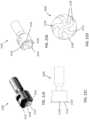
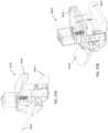
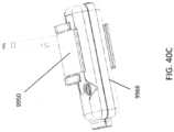
- An exemplary clamp 9310(which can be used as clamp 9110) is shown in FIGS. 34A-34E .
- the clamp 9310includes a clamp top jaw 9114, a clamp top cover 9111, a clamp bottom jaw 9120, and a clamp lever 9116.
- the jaws 9114, 9120can be configured to move towards one another to clamp a device therebetween.
- the clamp top cover 9111can include a support arm coupler 9112 and a cutout region 9117, both of which are disposed on the top surface of the clamp top cover 9111.
- the support arm coupler 9112can further include a support arm coupling aperture 9113 that may be mated with the clamp coupling post 9131.
- the support arm coupler 9112may also include sleeve bearings 9119 to provide better rotational movement by reducing friction between the clamp coupling post 9131 and the support arm coupler 9112.
- the cutout region 9117can be positioned opposite the support arm coupler 9112.
- the top piece cutout region 9117can function to retain a course adjustment knob 9118.
- the distance between the clamp upper jaw 9114 and the clamp lower jaw 9120may be adjusted to retain various sizes of rail or surface. Distances between the upper jaw 9114 and the lower jaw 9120 may range from 1.27 mm to 7.62 mm (0.5 - 3 inches). In some instances, the operator may turn the course adjustment knob 9118 when it is coupled to the clamp 9110 to adjust the initial distance between the top jaw 9114 and the bottom jaw 9120.
- a lever 9116can be configured to allow for vertical movement of the clamp lower jaw 9120.
- the lever 9116includes a lever handle 9123 and a lever stem 9124. By toggling the lever handle 9123 from one side to another and back, the operator may adjust the distance between the clamp upper jaw 9114 and the clamp lower jaw 9120.
- the lever 9116is in a shape that allows easy adjustment of the distance between the upper and lower jaws 9114, 9120 of the clamp 9110.
- the lever 9116includes a lever stem 9124 that mates with a side cam lever adjustor 9122.
- the lever 9116also includes a lever stem cutout 9125 that may be used to retain a post or dowel 9127 that allows for coupling to the side cam lever adjustor 9122.
- the side cam lever adjustor 9122includes a side cam lever adjustor aperture 9126 that couples to lever stem 9124. Furthermore the side cam lever adjustor aperture 9126 may further include a side cam lever adjustor aperture cutout 9128 that serves to more precisely mate with the lever stem cutout 9125 of lever 9116 through the dowel 9127 such that when the lever handle 9123 of lever 9116 is moved from one side to the other, the dowel 9127 is moved within the side cam lever adjustor aperture cutout 9128 and through the clamp bottom piece aperture 9121 to move the bottom jaw piece 9115 up and down.
- the side cam lever adjustor 9122may also include side cam lever adjustor coupling apertures 9129 for coupling to the upper jaw 9114 and the lower jaw 9120 pieces.
- the joining of the lever 9116 with the bottom jaw piece 9115 through the side cam lever adjustor 9122may also include washers for cushioning the movement of the lever with respect to the side cam lever adjustor.
- the clamp 9310may also include a spring 9331 to provide a more even force distribution against the bottom jaw piece 9115 when actuated by the side cam lever adjustor 9122.
- the lever 9116, side cam lever adjustor 9122, and clamp lower jaw 9120 ensemblemay further include other dowels, screws, and pins to provide smooth actuation of the clamp lower jaw 9120 when the lever 9116 is adjusted.
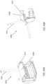
- FIGS. 37A-37BAn alternative clamp design 9610 (that could be used as clamp 9110) is shown in FIGS. 37A-37B .
- the clamp 9610functions in essentially the same manner as clamp 9210 for grabbing onto a rail or a surface.
- the primary difference between the clamps 9610 and 9210is that in clamp 9610, a lever 9616 that actuates a lower jaw 9620 (to bring it closer to the upper jaw 9614) can be flipped from an up and down direction, while clamp 9210 actuates the clamp with a side to side motion of its lever.
- cable retainers 9170can be used to maintain cables used for powering the medical device such that the cables do not become entangled.
- the cable retainers 9170can also keep the cables away from the patient and/or prevent the cables from needlessly obstructing the medical personnel's view of the patient or treatment site during a procedure.
- the series of cable management retainers 9170may be disposed along the length of segments 9134 and 9139.
- the cable management retainers 9170can be constructed to comfortably retain cables associated with the use of the medical device (e.g. power cables, signal cables, wires, and so forth).
- the cable management retainers 9170can keep necessary cables associated with the medical device component clear of where healthcare professionals may be working.
- the cable management retainer 9470includes a cable management top cover 9171 coupled with a cable management bottom piece 9175.
- the cable management top cover 9171includes a cable management top coupling channel 9172 that is capable of accepting a pin 9179.
- the cable management top cover 9171also includes a cable management torsion spring groove 9173 that is able to mate with a torsion spring 9180.
- the torsion spring 9180allows the cable management top cover 9171 to automatically snap back to a closed position after the cable management top cover 9171 has been flipped to an open position. This prevents cables or wires from inadvertently slipping out of the cable management retainer 9470 during the medical procedure and interfering with the medical procedure at hand.
- the cable management bottom piece 9175includes at least two cable management bottom channels 9176 such that when the cable management top coupling channel is seated between the two cable management bottom channels 9176 and a pin 9179 is inserted through the each of the channels, the cable management top cover 9171 mates with the cable management bottom piece 9175 and is able to pivot at with respect to the cable management bottom piece 9175.
- the cable management bottom piece 9175further includes a cable management bottom lip 9177.
- the cable management bottom lip 9177has a slanted outer edge such that when the cable management top cover 9171 is in contact with the cable management bottom piece 9175, the slanted outer edge comes into contact with the shorter side of the tapered edge of the cable management top cover 9171.
- the cable management top cover 9171can also be slightly tapered underneath. The advantage of this configuration is that a user can easily catch the longer side of the tapered edge of the cable management top cover 9171 with his finger and easily insert or remove cables of choice, even if wearing gloves.
- the cable management bottom piece 9175also includes at least one cable management bottom screw aperture 9178, which allows the cable management clasp 9170 to be coupled to the support arm 9130 or other portion of the support arm assembly 9100.
- the device mount 9150can be configured to couple with, and hold steady, a medical device component that is greater than 2.27 kg (5 pounds), greater than 4.54 kg (10 pounds), or greater than 6.80 kg (15 pounds), such as up to 9.07 kg (20 pounds).
- the device mount 9150can be configured to maintain a catheter drive controller during use of the catheter (e.g., an atherectomy catheter).
- the device mount 9550(which can be used as device mount 9150) is shown in FIGS. 36A-36B .
- the device mount 9550includes a device mount stem 9151. At one end of the device mount stem 9151, a device mount base 9152 is attached.
- the device mount base 9152extends perpendicularly away from the device mount stem 9151.
- the device mount stem 9151may include coupling pin apertures 9164 for coupling to the device mount base 9152 and the device mount latch 9153.
- the device mount base 9152also includes a device mount base stem aperture 9160 for coupling to the device mount stem 9151 and a device mount base post aperture 9161 that couples to the device mount post 9154.
- the device mount post 9154is configured to couple with the device component being supported so as to prevent the device component from detaching form the device mount 9550 during use and inadvertently injuring the patient.
- the device mount base 9152may also include coupling pin apertures 9164 that may be tightened or loosened for either coupling to the device mount stem 9151 or the device mount post 9154.
- the device mount 9550also includes a device mount latch 9153 at an intermediate position along the device mount stem 9151.
- the device mount latchincludes a device mount latch stem aperture 9162 for coupling to the device mount stem 9151.
- the device mount latch 9153may be adjusted along the device mount stem 9151 such that when a device has been coupled to the device mount post 9154, the device mount latch 9153 may be lowered to contact the top surface of the device component, where then the device mount post 9154 may be tightened locking its position along the length of device mount stem 9151 for steadying the device component within device mount 9550.
- the device component having a corresponding cavity for accepting the device mount post 9154may be swiveled to obtain the best viewing angle.
- the device mount latchmay be used to maintain the orientation of the device component during use. While not shown the device mount latch may include a cushioning layer on its surfaces that come into contact with the device component.
- the end of the device mount stem 9151 that is configured to couple to the device mount adjustor 9143 of the support arm 9130includes a device mount stem notch 9155.
- the device mount stem notch 9155encompasses the entire circumference of the device mount stem 9151.
- the device mount stem notch 9155allows the device mount 9150 to be snapped into, and held within, the device mount coupler 9142.
- the device mount coupler 9142may have include internal mechanisms (not shown) that allow it to grip onto the device mount stem notch 9155 of the device mount 9150.
- the device mount 9550when coupled to the support arm 9130, can rotate along at least one axis of rotation.
- the device mount 9150is able to rotate about the long axis of the device mount stem 9151.
- the device mount stem 9151may be coupled to the device mount coupler 9142 by any suitable means known in the art including but not limited to hooks, clasps, clips, and so forth.
- FIG. 36Cshows the device mount 9550 attached to a controller 9666, e.g., a controller for an atherectomy catheter.
- the device mount 9154can mate with a slot in the controller 9666, and the controller 9666 can rest on the base 9152.
- the device mount latch 9153can help maintain the controller 9666 within the device mount 9550.
- the device mount post 9154 heightmay range anywhere from approximately 1cm to 3cm.
- the device mount post 9154advantageously does not interfere with the circuitry, layout, or function of the device component.
- the device mount 9550is designed such that their weight when coupled to the device component provides reasonable counter weight to the support arm 9130 and thus does not over-stress the coupling between the clamp 9110 and its supporting element (e.g. bed rail).
- the device mountmay include some other type of coupling mechanism.
- the device mount basemay include one or more protrusions or locking mechanism that are able to mate with features on the device component.
- the device mount basemay include adjustable appendages that can grasp onto the device component or snap onto the device component.
- the device mountmay include female couplers that are able to make with corresponding male couplers on the device component or vice versa.
- FIG. 38shows another device mount 9750.
- the device mount 9750is in a "C" configuration, where the top portion includes a device mount flap 9253 and the bottom portion has a device mount support base 9252 that is able to support the dimensions of the device component instead of coupling to the device component through a single attachment point.
- the device mount flap 9253may be adjustable in distance with respect to the device mount support base 9252.
- the device mount flap 9253may be hingedly attached to the device mount support base 9252 such that it is able to hold the device component securely during use. It may also be possible for the device mount flap 9253 and the device mount support base 9252 to rotate about the longitudinal axis of a device mount post 9254.
- FIGS. 39A-39Bshow another device mount 9850.
- the device mount 9850includes a base against which the controller 9866 sits.
- a device mount post 9854can be configured to be rotated or screwed into a mating hole in the controller 9866 to hold it thereto.
- FIGS. 40A-40Cshow yet another device mount 9950.
- FIGS. 40A-40Bshows a device mount 9350 that is unattached
- FIG. 40Cshows the device mount 9250 securely attached to a controller 9966.
- device mount 9950has a "C"-shaped configuration with a device mount post 9354 for coupling to the support arm.
- the device mount 9350has an outer C holder 9357 and an inner C clasp 9358.
- the inner C clasp 9358may hingedly hold onto the device component during use. The distance between the two ends of the C clasp 9358 may also be adjusted to accommodate different device component heights.
- FIGS. 41A-41BAnother exemplary device mount 91050 is shown in FIGS. 41A-41B .
- the device mount 91050can be attached to a pivotable portion 91092 of a support arm 91000. Further, the device mount 91050 can include a base 91052 configured to sit horizontal such that the controller 91066 can rest thereon. Device mount posts 91054a,b can be configured to mate with corresponding apertures on the controller 91066 to hold it in place.
- the device mounts, support arm assemblies, and clamping mechanisms described hereincan all be designed to be able to balance the weight of the device component being held such that the clamp is able to maintain secure contact with the rail or surface onto which it is clamped.
- the device mount flap and/or the device mount support basemay include cushioning material on the surfaces that would contact the device component.
- the device mount portions that would contact the device componentmay include materials having greater friction so that the device component would not easily slip from the device mount while being maneuvered.
- Device mounts described hereinmay also include springs known in the art of clips and clamps that aid with maintaining pressure on the device component during use.
- the devicemay be otherwise oriented (rotated 90 degrees or at other orientations) and the spatially relative descriptors used herein interpreted accordingly.
- the terms “upwardly”, “downwardly”, “vertical”, “horizontal” and the likeare used herein for the purpose of explanation only unless specifically indicated otherwise.
- first and secondmay be used herein to describe various features/elements (including steps), these features/elements should not be limited by these terms, unless the context indicates otherwise. These terms may be used to distinguish one feature/element from another feature/element. Thus, a first feature/element discussed below could be termed a second feature/element, and similarly, a second feature/element discussed below could be termed a first feature/element without departing from the teachings of the present invention.
- a numeric valuemay have a value that is +/- 0.1% of the stated value (or range of values), +/- 1% of the stated value (or range of values), +/- 2% of the stated value (or range of values), +/- 5% of the stated value (or range of values), +/- 10% of the stated value (or range of values), etc. Any numerical range recited herein is intended to include all sub-ranges subsumed therein.
Landscapes
- Health & Medical Sciences (AREA)
- Life Sciences & Earth Sciences (AREA)
- Surgery (AREA)
- Animal Behavior & Ethology (AREA)
- Public Health (AREA)
- Engineering & Computer Science (AREA)
- Biomedical Technology (AREA)
- Heart & Thoracic Surgery (AREA)
- Medical Informatics (AREA)
- Molecular Biology (AREA)
- Veterinary Medicine (AREA)
- General Health & Medical Sciences (AREA)
- Nuclear Medicine, Radiotherapy & Molecular Imaging (AREA)
- Pathology (AREA)
- Vascular Medicine (AREA)
- Physics & Mathematics (AREA)
- Biophysics (AREA)
- Oral & Maxillofacial Surgery (AREA)
- Radiology & Medical Imaging (AREA)
- Surgical Instruments (AREA)
Description
- Peripheral artery disease (PAD) and coronary artery disease (CAD) affect millions of people in the United States alone. PAD and CAD are silent, dangerous diseases that can have catastrophic consequences when left untreated. CAD is the leading cause of death in the United States while PAD is the leading cause of amputation in patients over 50 and is responsible for approximately 160,000 amputations in the United States each year.
- Coronary artery disease (CAD) and Peripheral artery disease (PAD) are both caused by the progressive narrowing of the blood vessels most often caused by atherosclerosis, the collection of plaque or a fatty substance along the inner lining of the artery wall. Over time, this substance hardens and thickens, which can cause an occlusion in the artery, completely or partially restricting flow through the artery. Blood circulation to the arms, legs, stomach and kidneys brain and heart may be reduced, increasing the risk for stroke and heart disease.
- Interventional treatments for CAD and PAD may include endarterectomy and/or atherectomy. Endarterectomy is surgical removal of plaque from the blocked artery to restore or improve blood flow. Endovascular therapies such as atherectomy are typically minimally invasive techniques that open or widen arteries that have become narrowed or blocked.
- In certain instances of CAD and PAD, extensive coronary calcification may occur. An increased risk of coronary heart disease is associated with extensive coronary calcification and is a sign of advanced atherosclerosis. Calcified plaque is more difficult to break apart than non-calcified plaque masses. As such, current atherectomy cutters used may not be as effective for breaking down calcified plaques. Thus, it would be advantageous to have a cutter that is better able to attack calcified plaque deposits during an atherectomy procedure.
US 2011/130777 discloses an atherectomy catheter having an elongate catheter body, a drive shaft extending proximally to distally within the catheter body and a cutting element coupled to the drive shaft. The cutting element has a cutting edge and a cup-shaped surface at the distal end.US 6,579,298 discloses a system for ablating material in vein grafts that includes an ablation burr that is rotated by a drive shaft.US 2005/0222663 discloses an atherectomy device for removing material from a blood flow lumen. The device comprises: an elongate body, a rotatable cutting element, a torque shaft for rotating the cutting element and an opening for receiving severed tissue. The cutting element is movable relative to the opening between a retracted position and a deployed position. The distal portion of the rotatable cutting element can include a serrated knife edge and a curved or scooped distal surface.- Atherectomy catheter devices and the corresponding systems and methods that may address some of these concerns are described and illustrated below.
- The present invention provides an atherectomy catheter device according to claim 1.
- The atherectomy catheter of the present invention can include one or more of the following features. Each of the plurality of grinding segments can be a flat facet. The second curvature can be smaller than the first curvature. The serrated annular cutting edge can be angled radially inward relative an outer diameter of the elongate body. The annular cutting edge can extend radially inward relative an outer diameter of the elongate body by 2 degrees to 12 degrees. The plurality of grinding segments can be disposed symmetrically around a circumference of the recessed bowl. The plurality of grinding segments can be disposed asymmetrically around a circumference of the recessed bowl.
- Also described herein but not claimed are support systems for maintaining medical components, such as controller components of an atherectomy catheter, at a convenient location with easy maneuverability relative to the treatment site.
- One particular catheter controller support apparatus includes a rail clamp configured to releaseably attach to a rail, a support arm having at least two segments joined by a swivel joint that is configured to couple with the rail clamp through a coupling post, and a catheter controller mount coupled to the support arm and configured to securely maintain a catheter controller.
- This and other arrangements may include one or more of the following features. The rail clamp may include a top surface, a support arm coupler disposed on the top surface, a support arm coupling aperture disposed on the support arm coupler, a top jaw, a bottom jaw hinged with the top jaw, a lever for actuating the up and down movement of the top and the bottom jaw, and a support arm securing aperture for locking the support arm in position. The rail clamp may further include a course adjustment knob for increasing and decreasing the distance between the top jaw and the bottom jaw. The rail clamp may further include at least one sleeve bearing contained within the arm coupling aperture. The support arm may further include a first friction knob configured to maintain the swivel joint in a fixed position once the desired position is obtained. The support arm may further include a second swivel joint and a corresponding second friction knob adjacent to the coupling post configured to provide articulated/segmental adjustment of the support arm. The support arm may further include a catheter mount coupler adapted to couple to the catheter controller mount, wherein the catheter mount coupler may further include a mount positioning lever that configured to adjust the angle at which the catheter controller mount is positioned. The support arm may further include at least one cable retainer. The catheter controller mount may further include a catheter controller coupler, wherein the catheter controller coupler may be a post or other protrusion extending from the base of the catheter controller mount that inserts into a corresponding aperture of the catheter controller. The catheter controller mount may further include a controller mount support latch. The catheter controller mount may include a clip having a jaw wide enough to accommodate the catheter controller. The catheter controller mount may include a mount support base, a mount support coupler configured to couple to a catheter controller unit, and a mount support latch for stabilizing the coupled catheter controller unit.
- In general, in one arrangement, a catheter controller support apparatus includes a rail clamp configured to releaseably attach to a rail, a support arm coupler disposed on the top surface, a support arm coupling aperture disposed on the support arm coupler, a top jaw, a bottom jaw hinged with the top jaw, a lever for actuating the up and down movement of the top and the bottom jaw, and a support arm securing aperture for locking the support arm in position. The rail clamp includes a top surface. The support arm has at least two segments joined by a swivel joint that is configured to couple with the rail clamp through a coupling post. The at least two segments are coupled by a swivel joint and at least one friction knob maintains the swivel joint in a fixed position once the desired position is obtained. The catheter controller support apparatus further includes a catheter controller mount coupled to the support arm and configured to securely maintain a catheter controller. The catheter controller mount further includes a catheter controller coupler. The catheter controller coupler includes a post or other protrusion extending from the base of the catheter controller mount that inserts into a corresponding aperture of the catheter controller, a mount support base, a mount support coupler able to couple to a catheter controller unit, and a mount support latch configured to stabilize the coupled catheter controller unit.
- This and other arrangements may include one or more of the following features. The rail clamp may further include at least one sleeve bearing contained within the arm coupling aperture. The support arm may further include a catheter mount coupler configured to couple to the catheter controller mount, wherein the catheter mount coupler may further include a mount positioning lever that is configured to adjust the angle at which the catheter controller mount is positioned. The support arm may further include at least one cable retainer.
FIGS. 1A-1C illustrate a side perspective view of the end of an exemplary atherectomy device having an offset hinged region, a bushing, and an imaging/cutting assembly with a neck region that engages the bushing.FIG. 1B shows the catheter with the housing for the hollow distal tip removed.FIG. 1C shows the catheter ofFIG. 1B with the proximal connector to the outer sleeve of the elongate body removed, showing the bushing and rotatable drive shaft.FIG. 2A shows a sectional view though an atherectomy catheter such as the one shown inFIGS. 1A-1C , with the distal tip in-line with the elongate (proximal) body region.FIG. 2B shows the catheter ofFIG. 2A as the tip beings to be displaced downward.FIG. 2C shows the catheter ofFIG. 2A with the tip fully displaced downward, exposing the cutting edge of the cutting/imaging assembly.FIG. 3 shows a catheter with the cutting/imaging assembly extended distally into the distal tip region.FIGS. 4A-4D illustrate another variation of an atherectomy catheter.FIGS. 4B, 4C and 4D each show the catheter ofFIG. 4A with various components removed to allow description of internal parts.FIG. 5 illustrates a handle for an atherectomy catheter.FIG. 6 shows one variation of a distal end of an atherectomy having a plurality of balloons that are arranged and may be used to provide a mechanical advantage in driving the cutting edge against the vessel wall.FIGS. 7A-7D show perspective, side, top and front views, respectively of a bushing for an atherectomy device.FIG. 8A shows a panoramic OCT image of a blood vessel through the nosecone of an atherectomy catheter, as identified by the arrow inFIG. 8B .FIG. 9A shows a panoramic OCT image of a blood vessel taken with an atherectomy catheter through the cutting window(s) when the nosecone is closed and the cutter is in a passive position, as identified by the arrow inFIG. 9B .FIG. 10A shows a panoramic OCT image of a blood vessel taken with an atherectomy catheter through cutting window(s) when the nosecone is open, as identified by the arrow inFIG. 10B .FIGS. 11A-11B show another embodiment of an atherectomy catheter having a cutter engaging distal surface that is normal to the longitudinal axis of the catheter.FIG. 11A shows a cross-section of the catheter whileFIG. 11B shows a side view of the bushing.FIGS. 12A-12B show another embodiment of an atherectomy catheter having a cutter engaging distal surface that is at an angle relative to the longitudinal axis so as to provide only a point of contact with the distal surface of the cutter.FIG. 12A shows a cross-section of the catheter.FIG. 12B shows a side view of the bushing.FIG. 13A shows the removal of a single, long strip of material cut from the tissue by an atherectomy catheter as described herein.FIGS. 13B and 13C show the length of tissue removed.FIGS. 14A and 14B show a bushing having jet channels therethrough to assist in packing of tissue into the nosecone of an atherectomy catheter.FIG. 15 shows a cross-section of an atherectomy catheter with a crescent-shaped balloon.FIGS. 16A-16C show an atherectomy catheter with a crescent-shaped balloon.FIG. 17A shows an atherectomy catheter having a serrated cutting edge.FIG. 17B shows a close-up of the serrated cutter portion of the atherectomy catheter ofFIG. 17A .FIGS. 18A-18E show an atherectomy catheter cutter having a serrated cutting edge and an asymmetric pocket within the cutter body.FIGS. 18A and 18B are isometric views of the cutter.FIG. 18C is a side view of the cutter.FIG. 18D is a front view of the cutter.FIG. 18E is a cross-sectional side view of the cutter.FIGS. 19A-19E show an atherectomy catheter cutter having a serrated cutting edge and a symmetric pocket within the cutter body.FIGS. 19A and 19B show isometric views of the cutter.FIG. 19C is a side view of the cutter.FIG. 19D is a front view of the cutter.FIG. 19E is a cross-sectional side view of the cutter.FIGS. 20A-20E show an atherectomy catheter cutter having rotationally asymmetric depressions therein.FIGS. 20A and 20B show isometric views of the cutter.FIG. 20C is a side view of the off-axis cutter.FIG. 20D is a front view of the cutter.FIG. 20E is a cross-sectional side view of the cutter.FIGS. 21A-21E show an atherectomy catheter cutter having a helical depressions therein.FIGS. 21A and 21B show isometric views of the cutter.FIG. 21C is a side view of the cutter.FIG. 21D is a front view of the cutter.FIG. 21E is a cross-sectional side view of the cutter.FIGS. 22A-22B show an atherectomy catheter cutter having a smooth cutting edge having a series of pockets disposed within a bowl region.FIG. 22A is a perspective view of the cutter andFIG. 22B is a front view of the bowl region.FIGS. 23A-23B show an atherectomy catheter cutter having grooved cutting edges disposed on the outer rim of a bowl region, where the grooves also extend along the outer wall of the cutter.FIG. 23A is a perspective view of the cutter andFIG. 22B is a front view of the bowl region.FIGS. 24A-24B show an atherectomy catheter cutter having shallow cutouts in the cutting edge disposed on the outer rim of a bowl region. The shallow cutouts also extend along the outer wall of the cutter.FIG. 24A shows a perspective view of the cutter, whileFIG. 24B is a front view of the bowl region.FIGS. 25A-25B show an atherectomy catheter cutter having asymmetric grooves in the cutting edge disposed on the outer rim of a bowl region. The asymmetric groove also extends along the outer wall of the cutter.FIG. 25A shows a perspective view of the cutter, whileFIG. 25B is a front view of the bowl region.FIGS. 26A-26B show an atherectomy catheter cutter having a smooth cutting edge disposed around a bowl region of the cutter, where the outer wall of the cutter includes a series of grooves.FIG. 26A shows a perspective view of the cutter, whileFIG. 26B shows a front view of the bowl region.FIGS. 27A-27E illustrate an atherectomy catheter device including a cutter having a serrated annular cutting edge, a recessed bowl, and a plurality of segments according to one embodiment. Each of the segments is a flat facet having a concave portion on the cutting edge.FIG. 27A is a shaded perspective view of the cutter,FIG. 27B is a line perspective view of the cutter,FIG. 27C is a side view of the cutter,FIG. 27D is a front view of the cutter andFIG. 27E is a cross-sectional side view of the cutter.FIGS. 28A-28E illustrate an atherectomy catheter device including a cutter having a serrated annular cutting edge, a recessed bowl, and a plurality of segments according to another arrangement.FIG. 28A is a shaded perspective view of the cutter,FIG. 28B is a line perspective view of the cutter,FIG. 28C is a side view of the cutter,FIG. 28D is a front view of the cutter andFIG. 28E is a cross-sectional side view of the cutter.FIGS. 29A-29E illustrate an atherectomy catheter device including a cutter having a serrated annular cutting edge, a recessed bowl, and a plurality of segments according to one arrangement.FIG. 29A is a shaded perspective view of the cutter,FIG. 29B is a line perspective view of the cutter,FIG. 29C is a side view of the cutter,FIG. 29D is a front view of the cutter andFIG. 29E is a cross-sectional side view of the cutter.FIGS. 30A-30E illustrate an atherectomy catheter device including a cutter having a serrated annular cutting edge, a recessed bowl, and a plurality of segments according to one arrangement.FIG. 30A is a shaded perspective view of the cutter,FIG. 30B is a line perspective view of the cutter,FIG. 30C is a side view of the cutter,FIG. 30D is a front view of the cutter andFIG. 30E is a cross-sectional side view of the cutter.FIGS. 31A- 31E illustrate an atherectomy catheter device including a cutter having a serrated annular cutting edge, a recessed bowl, and a plurality of segments according to one arrangement.FIG. 31A is a shaded perspective view of the cutter,FIG. 31B is a line perspective view of the cutter,FIG. 31C is a side view of the cutter,FIG. 31D is a front view of the cutter andFIG. 31E is a cross-sectional side view of the cutter.FIG. 32A is a perspective view of a support arm assembly.FIG. 32B is an exploded view of the support arm assembly ofFIG. 32A .FIG. 32C is a top view of the support arm portion of the support arm assembly ofFIG. 32A .FIG. 33A is a perspective of an adjustment knob screw.FIG. 33B is an exploded view of the adjustment knob screw ofFIG. 33A .FIG. 34A is a perspective view of a side rail clamp.FIG. 34B is an exploded view of the side rail clamp ofFIG. 34A .FIG. 34C is a perspective view of the bottom jaw of the side rail clamp ofFIG. 34A .FIG. 34D is a perspective view of a side cam level adjustor of the side rail clamp ofFIG. 34A .FIG. 34E is a perspective view of the side cam lever of the side rail clamp ofFIG. 34A .FIG. 35A is a perspective of a cable retainer.FIG. 35B is an exploded view of the cable retainer ofFIG. 35A .FIG. 35C is a perspective view of a top jaw of the cable retainer ofFIG. 35A .FIG. 36A is a perspective view of a catheter controller mount.FIG. 36B is an exploded view of the catheter controller mount ofFIG. 36A .FIG. 36C shows the catheter controller mount ofFIG. 36A coupled to a catheter controller.FIGS. 37A-37B shows another rail clamp.FIG. 38 shows another catheter controller mount.FIGS. 39A-39B show another catheter controller mount coupled to a catheter controller.FIGS. 40A-40B show another catheter controller mount.FIG. 40C shows the catheter controller mount ofFIG. 40A coupled to a catheter controller.FIG. 41A shows another catheter controller mount.FIG. 41B shows the catheter controller mount ofFIG. 41A coupled to a catheter controller.- The atherectomy catheters described herein include a cutter. The cutter has a serrated annular cutting edge formed on a distal edge of the cutter and a recessed bowl extending radially inwards from the annular cutting edge to a center of the cutter. The recessed bowl includes a plurality of segments therein configured to help break up hard plaque or diseased tissue that enters the recessed bowl during use.
- The atherectomy catheters described herein can further include a catheter shaft with a drive chassis on the end. The drive chassis includes a stout torque coil ("imaging torqueing coil"/drive shaft) for rotating an imaging element, a cutter, and an imaging optical fiber in the center of the torque coil. Both the imaging elements and the cutter can be part of a head that rotates with the driveshaft. The head can rotate in a single direction (e.g., clockwise). The head can further slide distally/proximally by pushing or pulling the torque coil/drive shaft. As a result of the movement of the driveshaft, a nosecone configured to hold tissue can be displaced. In some embodiments, the nosecone can open and close using an off-axis hinge. In other embodiments, a cam member and cam slot can be used to open and close the nosecone.
FIGS. 1A-3 show an example of anatherectomy catheter 100 including a nosecone that deflects to expose a cutter. Theatherectomy catheter 100 can include acatheter body 101 having anouter shaft 111, acutter 103 at a distal end of thecatheter body 101, and anosecone 105 at a distal end of thecatheter body 101. Thenosecone 105 can further include a cuttingwindow 107 through which thecutting edge 112 of thecutter 103 can be exposed. Thenosecone 105 can be configured to deflect away from the longitudinal axis of thecatheter body 101 about ahinge point 1109, as described further below. This deflection can expose thecutter 103 through the cuttingwindow 107 and/or radially push thecutter 103 into a wall of the vessel in which the atherectomy catheter is inserted.- Referring to
FIGS. 1A-2C , thecutter 103 can be positioned between thecatheter body 101 and thenosecone 105 via abushing 155. In some embodiments, thecutter 103 can be an annular cutter with a sharpdistal edge 112. Thecutter 103 is attached to adrive shaft 113 configured to rotate thecutter 103. - Further, referring still to
FIGS. 2A-2B , theatherectomy catheter 100 can include animaging element 192, such as an OCT imaging element, within thecutter 103 and proximal to thecutting edge 112 of thecutter 103. Theimaging element 192 can include anoptical fiber 197 that runs substantially on-axis through the center of the elongate body, such as through thedriveshaft 113, to transmit the OCT signal. Further, theoptical fiber 197 can run straight throughout thecatheter body 101 without bending. Theoptical fiber 197 can be attached at the distal end to thecutter 103, such as in aslot 177 in thecutter 103. The slot can have a length that extends at least to the center of thecutter 103 so as to allow theoptical fiber 197 to remain on-axis without a bend through the length of thecatheter body 101 and thecutter 103. Aside from the attachment to thecutter 103, theoptical fiber 197 can be otherwise be free to float within the catheter body or driveshaft 113. In other embodiments, theoptical fiber 197 can be attached to thedrive shaft 113 along the length thereof. - As shown in
FIGS. 2A-2C , theimaging element 192 can include areflective element 199, such as a mirror. Thereflective element 199 can be located within theslot 177 in thecutter 103 to radially direct light from theoptical fiber 197 into the adjacent tissue (through the cutter window 107). Thereflective element 199 can be oriented at an angle relative to the axis of theoptical fiber 197, such as at a 35-55 degree angle, e.g. 45 degree angle, to reflect light into the tissue. The distal end of theoptical fiber 197 can be located less than 3mm from the cutting edge, such as less than 1mm from the cutting edge, such as less than 0.5mm. By having theimaging element 192 close to the cutting edge, the resulting image can advantageously align with the portions of the vessel being cut. - In use, the
outer shaft 111 can be configured to be turned, such as turned manually, to position thecutter window 107,cutter 103, and/or theimaging element 192 toward the desired location. Thedriveshaft 113 can then be rotated to rotate thecutter 103 and theimaging elements 197. Rotation of the cutter can provide cutting due to the rotational motion of the cutting edge and provide the rotation necessary to image the vessel wall via the imaging element. The drive shaft can be rotated at up to 2,000 rpm, such as approximately 1,000 rpm in a single direction, though rotation in both directions or at higher or lower speeds is possible. - Referring to
FIGS. 2A-2C , thedrive shaft 113 can further be configured to translate axially in the proximal and/or distal directions. Such axial movement of thedrive shaft 113 can open and/or close thenosecone 105 about the hinge point 1109 (e.g., a pin in the bushing 155) to expose or conceal and protect thecutting edge 112 of thecutter 103. For example, thebushing 155 can include aninner flange 170 that extends radially inwards. Theinner flange 170 can be positioned distal to thehinge point 1109. Thebushing 155 can further include sloped outerdistal surface 143 that angles radially inward from the distal end to the proximal end. Finally, thecutter 103 can include aproximal edge 166 and atapered neck 168 that gets narrower from thedriveshaft 113 to the head of thecutter 103. The interaction of these various elements can open and close thenosecone 105. - In one embodiment, proximal retraction of the
drive shaft 113 opens thenosecone 105 to expose the cutter. For example, as thedriveshaft 113 is pulled proximally, theproximal edge 166 of thecutter 103 is forced against the slopeddistal surface 143 of thebushing 155. Because the slopeddistal surface 143 angles radially inward from the distal end to the proximal end, thecutter 103 forces thebushing 155, and thus thenosecone 105, to deflect away from the longitudinal axis of thecatheter body 101, thereby opening the nosecone 105 (see the transition fromFIGS. 2A to 2B and 2B to 2C ). The cuttingwindow 107 can have an opening that is larger than the diameter of thecutter 103 and cuttingedge 112 to allow thecutter 103 to protrude out of thenosecone 105 when thenosecone 105 is deflected. - In one embodiment, distal movement of the
drive shaft 113 closes thenosecone 105. For example, as shown inFIGS. 2A-2C , when thedrive shaft 113 is pushed distally, thetapered neck 168 of thecutter 103 will correspondingly move distally. The distal movement of the taperedneck 168 causes theinner flange 170 of thebushing 155 to drag along the widening edges of the taperedneck 168, thereby lifting thebushing 155, and correspondingly, closing the nosecone 105 (see the transition fromFIGS. 2C to 2B and 2B to 2A ). Because the hinge point is proximal to theinner flange 170, a mechanical advantage is achieved that allows for complete closing of the nosecone. FIGS. 7A-7D show close-ups of thebushing 155. As shown, thebushing 155 can include two intersectingchannels necked portion 168 of the imaging subassembly therein when the nosecone is in the open configuration (channel 723) and the closed configuration (channel 721).Channel 721 extends through a long distal to proximal axis of thebushing 155 whilechannel 723 extends at an angle relative to channel 721 and overlaps therewith. Thebushing 155 can further include ahinge channel 745 formed through a top peripheral region of thebushing 155 so as to provide thepivot point 1109. Thehinge channel 745 can be transverse to thechannel 721.- Other mechanisms of opening and closing the nosecone are possible. For example, as shown in
FIGS. 4A-4D , in one embodiment, a catheter 200 (having similar features tocatheter 100 except the opening and closing mechanisms) can include acam slot 228 in thebushing 155 that angles toward the cuttingwindow 107 from the proximal end to the distal end. Further, acam member 290 can be attached to thecutter 103 and configured to extend through thecam slot 228. Thus, as thedriveshaft 113, and thuscam member 290, are pushed distally, thecam member 290 will move within the angled cam slot 180. The movement of thecam member 290 within the angled cam slot 180 causes thebushing 155, and thus the nosecone 150, to drop down. Conversely, to close the nosecone, thedriveshaft 113 can be pulled proximally, thereby causing thecam member 290 to ride within thecam slot 228 and pull thebushing 155 back into line with theelongate body 101. - Another mechanism of opening and closing a nosecone of an
atherectomy catheter 400a, b is shown inFIGS. 11A-11B and 12A-12B . Thecatheter 400a, b can have the same features ascatheter 100 except that the outerdistal surface 443a,b of thebushing 455a,b can be either normal to the longitudinal axis of the device (such that the angle α is 90 degrees), as shown inFIG. 11B or slanted radially outward from the distal end to the proximal end (such that the angle α is greater than 90 degrees and the angle with the longitudinal axis is less than 90 degrees), as shown inFIG. 12B . In the embodiment ofFIGS. 12A-12B , an angled space is provided between theproximal edge 166 of the cutter and thedistal surface 443b such that the only point of contact is an innerradial edge 444 of thebushing 455b. Thecatheter 400a will open and close similarly to as described with respect tocatheter 100. However, the catheter 500b will open slightly differently in that only the inner-mostradial edge 444 will interact with theproximal edge 166 of thecutter 103, as opposed to the entire surface 443, when thedriveshaft 113 is pulled proximally. Such a configuration can advantageously reduce friction while opening thenosecone 105. In some embodiments, theproximal edge 166 can be angled with respect to a longitudinal axis of the catheter; in such cases, the opposing surface 443 of the bushing 455 can be either parallel to or angled (acute or obtuse) with respect to theproximal edge 166. - As shown in
FIG. 3 , the atherectomy catheter 100 (or 200 or 400) can further include a mechanism for packing tissue into the nosecone, such as by moving the drive shaft axially. In one embodiment, movement of thedrive shaft 113 distally closes thenosecone 105. Moving thedrive shaft 113 further distally will move thecutter 103 into a passive position (i.e., against a distal edge of the window 107) where thecutter 103 can be protected by the edge of thewindow 107 to avoid undesired cutting of the vessel during use. Moving thedrive shaft 113 further distally will move thecutter 103 into thenosecone 105, thus packing tissue with a distal face of thecutter 103, as shown inFIG. 3 . Thecutter 103 can move more than 1.27 cm (0.5 inches), such as more than 2.54 cm (1 inch) or more than 5.08 cm (2 inches) into thenosecone 105 to pack the tissue. In some embodiments, thenosecone 105 is formed of a material that is OCT translucent (e.g., non-metallic) so that panoramic OCT images can be taken therethrough. - Referring to
FIGS. 14A-14B , in some embodiment abushing 1655 can include all of the features of the bushings described above, but can additionally includejet channels 1785a,b cut into the inner circumference thereof and extending from the proximal end to the distal end. Thejet channels 1785a,b can connect a fluid line within theelongate body 101 to thenosecone 105. Fluid flowing through thejet channels 1785a, b can increase speed and thus provide enough force to pack cut material into the nosecone and clear the imaging region within the nosecone. Further, the jet channels can create a venturi effect at the distal end of thebushing 1655, which can suck material into the nosecone and/or away from the imaging/cutting head and/or the distal end region of the elongate body. - In one embodiment, the atherectomy catheter 100 (or 200 or 400) includes a guidewire lumen in the
nosecone 105, such as a monorail, for use in guiding the catheter. Advantageously, the guidewire lumen can be used as a marker during imaging. - In some embodiments of
atherectomy catheters small imaging windows nosecone 105 opposite to the cuttingwindow 107, as shown inFIGS. 1A and2A-2C . Theseadditional imaging windows 207 can provide more of a 180 degree view during imaging. Further, one set ofwindows 207 can be more proximal and configured to be axially aligned with thecutter 103 and theimaging element 192 when the nosecone is opened while the other set ofwindows 307 can be more distal and configured to be axially aligned with thecutter 103 and theimaging element 192 when the nosecone is closed and thecutter 103 is in the passive position. In some embodiments, theimaging windows - Referring to
FIGS. 8A-11B , the OCT image catheter with the device will vary depending upon the placement of the imaging device in the three different configurations (nosecone open, nosecone closed with cutter in cutting position, nosecone closed with cutter in packing position). Accordingly, a user can identify, simply by looking at the imaging display, whether thenosecone 105 is displaced and whether thecutter 103 is in the cutting or packing position. - For example,
FIG. 8A shows apanoramic image 800 of a surrounding vessel when the cutter 103 (and, correspondingly, the imaging sensor) is in the cutting position, as shown inFIG. 8B . The wall of thenosecone 105 is displayed as thecircular feature 808 in theimage 800. Further, because thenosecone 105 is made of a clear material, thevessel tissue 806 can be imaged even through thenosecone 105. As can be seen inimage 800, a 180 degree view of thetissue 806 can thus be obtained. Thecircular artifact 803 in the image (and here, the radial line 801) correspond to a guidewire and/or guidewire channel running alongside thenosecone 105. - In contrast to image 800,
FIG. 9A shows apanoramic image 900 of a surrounding vessel when thecutter 103 is in the passive position and thenosecone 105 is closed, as shown inFIG. 9B . A 180 degree view of thevessel tissue 906 is shown on the right side of the image (taken through window 107) while the closed nosecone 909 is shown on the left side of the image (thelines 909a,b correspond to the bushing wall). Thespace 913 between thelines 909a,b through whichtissue 906 can be seen on the left side of the image is taken through theadditional window 307 in the bushing. Further, the distance between the arrows inimage 900 indicates that the distal tip is "closed" (and close therefore close to the midline of the catheter). - Finally, in contrast to image 900,
FIG. 10A shows apanoramic image 1000 of a surrounding vessel when thecutter 103 is in the cutting position and thenosecone 105 is open, as shown inFIG. 10B . The vessel tissue 1006 (taken through window 107) is shown on the right side of the image while the closed nosecone 1009 is shown on the left side of the image (thelines 1009a,b correspond to the bushing wall). Thespace 1013 between thelines 1009a,b through whichtissue 1006 can be seen is taken through thewindow 207. A comparison of the relative distance between the arrows inFIGS. 9A and10A shows an increased distance between the catheter body and the nosecone, thereby suggesting to the operator that thenosecone 105 is in an open position. Further, in some embodiments, when the nosecone is open or closed, the image resulting from thewindow 207/307 will look different due to the angle change between thewindows 207/307 and the imaging element 297 and/or the different shape of thewindows 207/307. - In one embodiment, the atherectomy catheter 100 (or 200 or 400) includes a flush port close to the
cutter 103. The flush port can be used to deliver flushing fluid to the region of imaging, thereby improving image quality. In some embodiments, the flushing can be activated through a mechanism on the handle of the device. The fluid can, for example, be flushed in the annular space between thecatheter body 101 and thedriveshaft 113. Further, in embodiments with jet channels in the bushing, the annular space can connect to the jet channels to provide fluid thereto. - Referring to
FIG. 6 , in some embodiments, theatherectomy catheters cutter 103 into the tissue. Thefirst balloon 333 can be the distal-most balloon. Thefirst balloon 333 can be positioned proximate to thehinge point 1109 and opposite to the cutting window 1107. Theballoon 333 can urge thecutter 103 against the tissue by deflecting thecutter 103 up and into the tissue. Asecond balloon 335, proximal to thedistal balloon 333, can be on the same side of thecatheter 100 as the cuttingwindow 107 and can further help drive thecutter 103 into the tissue by. In some embodiments, thesecond balloon 335 can be annular. In some embodiments, thesecond balloon 335 can help occlude the vessel. Further, in some embodiments (and as shown inFIG. 6 ), athird balloon 337 can be used for occlusion. One or more of theballoons balloons cutter 103 into the tissue. Theballoons - Referring to
FIGS. 15 and16A-16C , in another embodiment, theatherectomy catheters cutter 103 into the tissue and occlude blood flow to improve imaging. Referring toFIG. 15 , theballoon 1733 can have a crescent shape, i.e., can be wrapped around thecatheter 100 so as to cover the entire circumference of thecatheter 100 except where thecutter 103 is exposed. By using aballoon 1733 with such a shape, the gaps between thecatheter 100 and thevessel 1723 are substantially reduced, advantageously negating or reducing the localized flushing required to displace blood from the visual field. In one embodiment, to create the crescent shape, the balloon includes wide necks at both ends that are then wrapped around thenosecone 105 andelongate body 101 such that they cover at least half of the circumferential surface.FIG. 16A shows the wrappedballoon edges 1735 whileFIG. 16B shows thewide necks 1737 fused at both ends.FIG. 16C shows an inflation port 1739 contained inside theballoon 1733 as well as aguidewire lumen 1741 that spans the length of theballoon 1733. In some embodiments, theballoon 1733 can be used to open or close the nosecone without requiring proximal or distal movement of the driveshaft. - Referring to
FIG. 5 , ahandle 300 can be used to control the rotation or translation of the driveshaft for thecatheter handle 300 can advantageously allow the optical fiber to move distally and proximally with the cutter as it is driven without requiring the fiber to move at a proximal location, e.g., without requiring movement of the optical fiber assembly within the drive assembly. Thus, thehandle 300 can be designed to completely account for movement of the drive shaft. An exemplarydriveshaft management system 555 is shown inFIG. 5 . Thedriveshaft management system 555 allows the user to position the driveshaft distally or proximally as the driveshaft is simultaneously spinning at a high speed. In some embodiments, the driveshaft can be configured such that it is fully tensioned before thedriveshaft management system 555 is positioned at its most proximal position. That is, thedriveshaft management system 555 can include adriveshaft tensioning spring 556. Thespring 556 can be configured such that, as the user positions the slideable user ring 557 (or button) proximally, the driveshaft is fully tensioned and thedriveshaft management system 555 is moved proximally, causing thespring 556 to compress and apply a controlled tensile load on the driveshaft. Thisfiber management system 555 advantageously enhances performance of the catheter by tensioning the driveshaft with a pre-determined load to properly position the cutting and imaging component against the bushing at the distal end of the catheter, improving cutting and imaging of the catheter. - The
driveshaft management system 555 can transmit torque originating from a drive assembly, as described further below. Connection to the drive assembly can be made at theoptical connector 559. Torque can thus be transmitted from theoptical connector 559, through thefiber cradle 551, to thedrive key 560, through thedriveshaft management system 555, and then directly to the catheter driveshaft, all of which can rotate in conjunction. Thefiber cradle 551 can include a set of components (i.e., a pair of pieces to make the whole fiber cradle) that houses the proximal end of the optical fiber and transmits torque within the driveshaft system. The fiber cradle components can be thin-walled by design, thereby creating a hollow space inside. Within this hollow space of thefiber cradle 551, the optical fiber can be inserted or withdrawn as the device driveshaft is positioned proximally or distally. As the fiber is inserted into thefiber cradle 551 when theuser ring 557 is positioned proximally, the fiber is able to coil within the internal space of thefiber cradle 551 while maintaining imaging throughout its length to the distal tip. Conversely, as the fiber is withdrawn from thefiber cradle 551 when theuser ring 557 is positioned distally, the coiled section of fiber is able to straighten while maintaining imaging throughout its length to the distal tip. This design feature advantageously provides more fiber capacity or "slack" to the overall driveshaft system to increase the range in which the driveshaft system can be translated. - The
handle 300 can further include aballoon inflation chamber 552 configured to connect to a balloon inflation lumen (e.g., for use with a balloon on the catheter as described above) on one side and to ballooninflation tubing 553 and/or aport 554 on the other side. Because the inflation fluid transfers to the balloon through theballoon inflation chamber 552, theouter shaft 111 can advantageously rotate (e.g., by rotating the knob 558) independently of theballoon inflation chamber 552, allowing thetubing 553 and/orport 554 to remain stationary during rotation of theouter shaft 111. - Moreover, as shown in
FIG. 5 , thehandle 300 can further include a catheterflush chamber 663 and catheterflush tubing 664 and/orflush port 665 to provide flushing through the catheter, as described above. - Any of the atherectomy catheters described above can be used with a cutter having a serrated distal edge designed to remove calcified and hard fibrous disease in an artery. The calcified and hard fibrous disease can be difficult to remove due to its increased hardness compared to plaque. While a standard cutter may have no problem debulking the majority of arterial plaque, in certain instances, the plaque encountered by an atherectomy catheter may be harder and/or of a greater volume than what is typically encountered. This may be due to plaque having a larger percentage of calcium, fibrin, and other cellular waste relative to the percentage of fat and cholesterol. A serrated or scalloped cutter with a serrated cutting edge can facilitate cutting and breaking away calcified and fibrous disease. The serrated edge can advantageously initiate the cut into the calcium by utilizing a large force over a small area, thereby providing the greatest cut efficiency to engage and cut the hardened disease.
FIGS. 17A-17B show anexemplary atherctomy catheter 1700 with aserrated cutter 1703. Thecatheter 1700 includes acatheter body 1701 and anosecone 1705 hinged to thecatheter body 1701 at an off-axis hinge point 1709. As in other embodiments, thenosecone 1709 can be configured to collect tissue therein. In some embodiments, thecutter 1703 can be moved distally to pack tissue into the nosecone. When thenosecone 1705 is deflected, theserrated cutting edge 1710 of thecutter 1703 can be pushed into the tissue. Aballoon 1733, when inflated, can also aid in moving thecutting edge 1710 towards the tissue.FIGS. 18A-31E illustrate various serrated cutters that can be used, for example, withatherectomy catheter 1700, to break down calcified and hard fibrous disease in the artery. The serrated cutting edge can spin at a high speed with various serrated geometries configured to engage hard calcified and fibrous disease in the diseased arteries.FIGS. 18A-18E show a first variation of aserrated cutter 1800 designed for removing calcified plaque. AsFIGS. 18A-18E show, theserrated cutter 1800 has aproximal end 1802 and adistal end 1804. Theproximal end 1802 is attachable to drive shaft of an atherectomy catheter. Thedistal end 1804 includes acutting edge 1810 along the circumference of theserrated cutter 1800 that includesteeth 1812. Theteeth 1812 create saw-like serrations along theedge 1810 that are configured to cut into calcified tissue. Thus, as thecutter 1800 is rotated, theteeth 1812 of thecutting edge 1810 contribute to better purchase and grabbing of calcified deposits for breakage and/or removal of the deposits.FIG. 18E shows the cross-sectional side view of thecutter 1800 attached to adriveshaft 1813.- The
serrated cutter 1800 also includes a symmetric and concave or recessedbowl 1814 extending radially inwards from thecutting edge 1810 to the central axis of thecutter 1800. Further contained within the bowl region is an asymmetric cavity 1816 (i.e., extending off of a central axis of the cutter 1800). Theasymmetric cavity 1816 covers between 1/3 and 1/2 of the surface area of thebowl region 1814 ofcutter 1800. Theasymmetric cavity 1816, as shown inFIG. 18D , includes three regions that further aid with breaking up of the harder forms of plaque. Further,seams 1815 delineate the three regions of theasymmetric cavity 1816 may protrude slightly above the surface of theasymmetric cavity 1816 walls, where theseams 1815 may be sharp or may include grabbing features that further aid with gripping onto and breaking apart calcified plaque deposits. It is also conceivable that the asymmetric cavity includes greater or less than three regions. As thecutter 1800 is rotated, theasymmetric cavity 1816 advantageously breaks up the calcium plaque within thebowl 1814 as the off-axis sidewalls and/or seams hit the rigid pieces within thebowl 1814, advantageously avoiding having the calcified plaque fold back onto itself (which can cause stalling of the cutter). - Each
tooth 1812 of thecutter 1800 borders a grindingsegment 1818. The grindingsegments 1818 are depressions or scoops in thebowl 1814 that have a greater curvature than thebowl 1814. The grindingsegments 1818 have a concave curvature at thedistal end 1804 of the cutter 1800 (as seen inFIGS. 18C and18E ). The grindingsegments 1818 of theserrated cutter 1800 are largely semi-circular in shape and disposed equidistantly about the perimeter ofcutter 1800. The grindingsegments 1818 can have sharp edges or points therearound that are configured to grind, sever, and/or grab onto the calcified plaque by applying more pinpointed force to the calcified plaque encountered while the cutter is rotating. In other variations, the grindingsegments 1818 disposed about the circumference ofcutter 1800 may be otherwise shaped (e.g. square or rectangular cut outs, triangular cut outs, symmetric, asymmetric, and so forth). Further, the grindingsegments 1818 can be either equidistantly disposed about the cutter perimeter or can be more unevenly or non-uniformly disposed about the cutter perimeter. FIGS. 19A-19E shows drawing of a second variation of aserrated cutter 1900 designed for removing calcified plaque deposits. Theserrated cutter 1900 shown inFIGS. 19A-19E possess many of the same features as thecutter 1800 shown inFIGS. 18A-18D , such as aserrated cutting edge 1910 havingteeth 1912 and half-circular grinding segment 1918s disposed evenly along the circumference of thecutting edge 1910. Similar to the design shown inFIGS. 18A-18E , the grindingsegments 1918 can be depressions within thebowl 1914 that are disposed along the perimeter of thecutter 1910. The grindingsegments 1918 can aid with grabbing and grinding into calcified plaque as the cutter rotates and are able to impart targeted force on the calcified plaque encountered and more easily break off the harder plaque formations. Thebowl 1914 is symmetric and recessed in essentially in the shape of a half sphere for accommodating larger plaque formations. In some variations, thebowl region 1914 may also include additional features that can further aid with grabbing and breaking apart calcified plaque as the cutter rotates. Additional features may include protrusions, or cavities about its sidewalls that are either symmetrically or asymmetrically distributed along the wall. The protrusions may have a sharp edge or point while the cavity may have a sharp edge, where these features aid with gaining purchase of the calcified plaque during the procedure. There may also be features at the base of the bowl that aid with gripping and purchase while the serrated cutter is rotating.- Another variation of a
serrated cutter 2000 for easier debulking of calcified plaque is shown inFIGS. 20A-20E . Theserrated cutter 2000 includes abowl region 2014 having aserrated cutting edge 2010 disposed along its perimeter. Thecutting edge 2010 includes a plurality ofteeth 2012 extending therearound with a plurality of grindingsegments 2018 therebetween. The grindingsegments 2018 can form a deeper scooped portion along theserrated edge 2010. The grinding segments 1218 can extend radially inwards towards and past the center of thebowl 2014 in an off-axis or spiraled manner. While the scooped grindingsegments 2018 are shown inFIG. 20D in a symmetric pattern, as thecutter 2000 rotates, the scoopedregions 2018 creates rotational asymmetry within thebowl region 2014 that allows the walls of the grindingsegments 2018 to grab onto the plaque and scoop the plaque out and break the plaque up. The combination of theteeth 2012 and the off-axis scoop cuts of the grindingsegments 2018 provide enhanced cutting and grinding of calcified plaque as thecutter 2000 rotates. Theteeth 2012 and/or grindingsegments 2018 may further include edges orseams 2016 that are raised with respect to the surface of the scoopedregions 2018 to further aid with gripping the calcified plaque during use. Furthermore, thebowl 2014 and/or the off-axis scooped regions may also include other gripping texture or features that are able to further enhance the purchase of the cutter on plaque deposits encountered during use of the cutter. FIGS. 21A-21E show another variation of aserrated cutter 2100 that is well-suited for debulking calcified plaque.Serrated cutter 2100 also includes aserrated cutting edge 2110 along the circumference ofcutter 2100.Serrated cutter 2100 also includes abowl region 2114.Cutter 2100 further includes a series ofteeth 2112 and a series of scooped out grindingregions 2118 that each begin at thecutting edge 2114 and extend inward towards the center of thebowl region 2114. The edge of the scooped outregion 2118 correspond to concave portions along the perimeter of thecutting edge 2110. As the cutter rotates, theteeth 2112 and the scooped grindingsegments 2118 aid greatly with gaining purchase of the calcified regions and providing targeted force onto the calcified plaque. In this example, the series of scooped grindingsegments 2118 are arranged in a helical patter withinbowl region 2114. Thehelical cutting pattern 2118 can advantageous help grab onto plaque and cut the plaque when the cutter is rotating.Cutter 2100 may also includeadditional features 2116 within thebowl 2114 that increase the cutter's gripping ability while in use.FIGS. 22A and 22B show acutter 2200 having no serration along the outer circumference. Thecutter 2200, similar to the other cutters already described, includes abowl region 2214. Thecutter 2200 has acutting edge 2210 along its outer perimeter. Thecutting edge 2210 is smooth and continuous. Rather than having serrations,cutter 2200 has a series of breaker pockets or grindingsegments 2218 distributed along an inner circumference of thebowl region 2214. Each grindingsegment 2218 includes a cavity (having a greater curvature than the bowl 2214) for aiding in gripping onto hardened plaque and serve to break up and debulk calcified plaque encountered. The grindingsegments 2218 can be in the shape of a circle or an oval. The intersection between the grindingsegments 2218 and the areas of thebowl regions 2214 may possess sharpened edges that further aid with gripping and breaking up of hardened plaque. As thecutter 2200 rotates, the grindingsegments 2218 can aid with further crushing of the plaque formations and sending these broken down plaque into the nosecone region. While the grinding segments shown inFIGS. 22A and 22B are symmetric and evenly distributed within the bowl region, in some arrangements, the breaker pockets may be asymmetric in shape and may not all be of the same size.- In some instances, hydraulic pressure may be present due to the tight fit between the major, outer diameter of the cutter and the inner diameter of the catheter's nosecone. Turning to
FIGS. 23A and 23B ,cutter 2300 includes features that may be able to alleviate some or all of the hydraulic pressure. Like many of the cutters previously discussed, thecutter 2300 includes abowl region 2314 and aserrated cutting edge 2310 disposed therearound. Here, theteeth 2312 are separated by V-shapedgrooves 2323 distributed around the perimeter of thebowl region 2314. Further, the V-shapedgrooves 2323 ofcutter 2300 may extend along anouter wall 2320 ofcutter 2300 such that where the V-shaped grooves 2318 occur, corresponding V-shapedchannels 2319 extend from the V-shapedgroove 2323 along the entire length ofcutter 2300's outer wall. The V-shapedchannels 2319 spaced around the outer wall ofcutter 2300 serve to relieve any hydraulic pressure that may be generated in the nose cone when the cutter is slid forward deeper into the nosecone and subsequently when the cutter is drawn back during rotation of the cutter. - Turning to
FIGS. 24A and 24B , acutter 2400 is shown. Thecutter 2400 includes abowl region 2414 and aserrated cutting edge 2410 disposed along the perimeter of thebowl region 2414. Theserrated cutting edge 2410 includes a plurality ofteeth 2412 separated by shallow cutouts 2423 in thecutting edge 2410. In this variation of the cutter, the shallow cutouts 2423 extend along anouter wall 2420 of thecutter 2400 to form arounded channels 2419 that are disposed on theouter wall 2420 of thecutter 2400. Therounded channels 2419, similar to the V-shapedchannels 2319 described earlier, can serve to relieve hydraulic pressure that may build up while the rotating cutter is pushed into the nosecone of the catheter. FIGS. 25A and 25B shows acutter 2500, another variation of cutter designs that include grooves along the outer wall of the cutter. Here, thecutter 2500 includes abowl region 2514 and aserrated cutting edge 2510 disposed along the perimeter of thebowl region 2514. Thecutting edge 2510 is formed byteeth 2510 separated by v-shapedrecesses 2512. The v-shapedrecesses 2523 are asymmetric such that thechannels 2519 that are formed from the asymmetric recessedregions 2512 and that extend along anouter wall 2520 of thecutter 2500 are also asymmetric in nature. An advantage of having asymmetric grooves disposed along the outer wall of the cutter is that there is less likelihood that the groove edges from catching on the inner diameter of the nosecone as the cutter is rotating.- Another variation of a
cutter 2600 is shown inFIGS. 26A and 26B . Thecutter 2600 includes abowl region 2614 and acutting edge 2610 disposed along the perimeter of thebowl region 2614. Here, thecutting edge 2610 has a smooth cutting surface about the outer perimeter of thebowl region 2614. Thecutter 2600 further includesangled channels 2619 disposed around theouter wall 2620 of thecutter 2600. Theangled channels 2619 preserves thesmooth cutting edge 2610 by originating on theouter wall 2620 of thecutter 2600 just below thecutting edge 2610 and extending away from thesmooth cutting edge 2610. Thecutter 2600 may be used in scenarios where the plaque encountered are not of the hardened and calcified variety and where a smooth cutting edge can successfully debulk the plaque encountered. The grooves arranged around theouter wall 2620 are able to minimize the buildup of hydraulic pressure when the cutter is pushed and subsequently pulled back from the catheter nosecone. FIGS. 27A-27E illustrate an exemplary embodiment of aserrated cutter 2700 having a serratedannular cutting edge 2710, a recessedbowl 2714, and a plurality of grindingsegments 2718. Thecutter 2700 includes the recessedbowl 2714 extending radially inwards from theannular cutting edge 2710 to a center of thecutter 2700. The recessedbowl 2714 can extend radially inwards from thecutting edge 2710 with a converge angle. For example, the converge angle of the recessed bowl can be 90 degrees, as shown inFIG. 27E .- The
cutter 2700 can further include a plurality of grindingsegments 2718 or dimples within thebowl 2714 and extending radially inwardly from thecutting edge 2710. The plurality ofsegments 2718 can each have a substantially circular or ovoid shape. In some other embodiments, the plurality ofsegments 2718 may be otherwise shaped. Further, each of the plurality ofsegments 2718 can have a curvature that less than the curvature of thebowl 2714. As shown inFIGS. 27A-27D , each of the plurality of grindingsegments 2718 can be a flat facet (i.e., such that the curvature is zero and the radius of curvature is infinite). The plurality of grindingsegments 2718 can advantageously break the uniformity of the recessed bowl 271, thus facilitating breaking hard substances such as calcium. The number of segments can be 2, 3, 4, 5, 6, 8, 12 or any number therebetween. For example, thecutter 2700 can have sixgrinding segments 2718 as shown inFIGS. 27A-27E . Further, the plurality of grindingsegments 2718 can be either equidistantly disposed about the cutter perimeter or can be more unevenly or non-uniformly disposed about the cutter perimeter. The plurality ofsegments 2718 can be disposed symmetrically or unsymmetrically around the circumference of thecutting edge 2710. - As shown in
FIGS. 27A-27E , each of the plurality ofsegments 2718 forms aconvex tooth 2712 of the serratedannular cutting edge 2710. Theconvex teeth 2712 are a portion of a circular shape or elliptical shape or other convex shape. The convex shapedteeth 2712 can be advantageous because there no sharp points are formed along a distal-most circumference of thecutting edge 2710. Since there is a constant force being applied along the arc from cutting tissues, the convex shaped portions are gentle in contact with tissue and have a long cutting length, thus engaging again tissue for a long time. The plurality ofconvex teeth 2712 can be configured to grind and grab onto the calcified plaque by applying pinpointed force to the calcified plaque encountered while the cutter is rotating. - As shown in
FIG. 27C andFIG. 27E , the serratedannular cutting edge 2710 can angled radially inward relative an outer-most circumference of the cutter 2710 (and/or relative to the elongate body of the catheter to which it is attached). The outer side wall of thecutter edge 2710 on thedistal tip 2704 can have an angle α relative to a sidewall of the outermost circumference of the cutter 2700 (or of the attached catheter body) along a longitudinal direction. The angle α is advantageous such that thecutting edge 2710 does not cut through the nosecone itself. The angle α can be between 2 to 12 degrees in some embodiments. For example, the angle α can be 5 degrees. Thedistal tip 2704 of the serratedannular cutting edge 2710 can extend radially inward relative an outer diameter of the elongate body by 2 degrees to 12 degrees. The serratedannular cutting edge 2710 can be angled radially and converged to a center axis of thecutter 2700 with a converge angle between 4 degrees and 20 degrees. For example, the converge angle can be 10 degrees in some embodiments as shown inFIG. 27E . FIG. 28A-28E illustrate anotherserrated cutter 2800 having a serratedannular cutting edge 2810, a recessedbowl 2814, and a plurality of grindingsegments 2818. The serratedannular cutting edge 2810 can have a plurality ofteeth 2812. As shown inFIGS. 28A-28E , each of the plurality ofsegments 2818 can form concave edges between theteeth 2812 of the serratedannular cutting edge 2810. The curvature of the grindingsegments 1818 can be greater than the curvature of thebowl 2814, thereby forming depressions or cavities in thebowl 2814. The number of segments can be 2, 3, 4, 5, 6, 8, 12 or any numbers therebetween. For example, thecutter 2800 can have seven recessed grindingsegments 2818 as shown inFIGS. 28A-28E . Further, the plurality of grindingsegments 2818 can be either equidistantly disposed about the cutter perimeter, as shown, or can be more unevenly or non-uniformly disposed about the cutter perimeter. The plurality ofsegments 2818 can be disposed symmetrically, as shown, or unsymmetrically around the circumference of thecutting edge 2810.- As shown in
FIG. 28C , the serratedannular cutting edge 2810 can be angled radially inward relative an outer diameter of the cutter 2800 (and/or the elongate body of the catheter). The outer side wall of thecutter edge 2810 forms an angle β relative to a sidewall of the elongate body of thecatheter 2800 along a longitudinal direction. The angle β can be between 2 to 12 degrees in some arrangements. For example, the angle β can be 5 degrees. The distal tip of the serratedannular cutting edge 2810 can extend radially inward relative an outer diameter of the elongate body by 2 degrees to 12 degrees. The angle β advantageously ensures that thecutting edge 2810 does not cut through the distal tip or nosecone of the catheter. The serratedannular cutting edge 2810 can be angled radially and converged to a center axis of thecutter 2800 with a converge angle between 4 degrees and 20 degrees. For example, the converge angle can be 10 degrees as shown inFIG. 28E . FIGS. 29A-29E illustrate acutter 2900 including a serratedannular cutting edge 2910 withteeth 2912 and a recessedbowl 2914. Theatherectomy cutter 2900 can be similar to thecutter 2800 except that the cutter can include fivegrinding segments 2918 rather than seven. Further, each of thesegments 2918 can be longer, e.g., extend a greater distance along the circumference of thecutting edge 2910, than incutter 2800.FIGS. 30A-30E illustrate acutter 3000 including a serratedannular cutting edge 3010 withteeth 3012 and a recessedbowl 3014. Thecutter 3000 can be similar tocutters segments 3018. The grindingsegments 3018 can form a substantially half-circle shape.FIGS. 31A-31E illustrate acutter 3100. Thecutter 3100 can be similar tocutter 3000 except that the grindingsegments 3118 can be further closer to one another, thereby making theteeth 3112 shorter. For example, the cutting edge of eachtooth 3112 ofcutter 3100 can be approximately 0.1-0.3, such as approximately 0.25, of the length of cutting edge of each grindingsegment 3118. In contrast, the cutting edge of eachtooth 3012 can be approximately 0.4-0.6, such as 0.5 of the length of the cutting edge of each grindingsegment 3018. In some arrangements, thecutter 3100 can also be smaller in size overall (e.g., be configured to sit within a 7 French catheter 1 French is equivalent to 0.33 mm) than the cutter 3000 (which can be configured, for example, to sit within an 8 French catheter).- The cutters described herein can be used, for example, for above the knee atherectomy procedures. In such procedures, the cutter can be designed to fit in an 8 French catheter and thus can have a diameter, for example, of between 1.78 mm and 22.86 mm (0.07 inches and 0.9 inches), such as approximately 1.96 mm (0.077 inches). The cutters described herein can also be used, for example, for below the knee atherectomy procedures. In such procedures, the cutter can be designed to fit in a 7 French catheter and can have a diameter, for example, of between 1.27 mm and 1.78 mm (0.05 inches and 0.07 inches), such as approximately 1.65 mm (0.065 inches). The recessed bowl in the cutters described herein can advantageously help collect and push cut tissue or plaque into the collection chamber in the nosecone of the atherectomy device.
- The cutters described can be useful for gripping on to and breaking apart calcified plaque deposits found within the arteries as well as softer forms of plaque that may be encountered. Because calcified plaque is much harder than its softer plaque counterparts, repeated use of the cutter for breakoff and clearing calcified plaque can easily lead to dull cutting edges that are less proficient at grabbing onto and breaking off calcified plaque during subsequent use. Thus, in some examples of the serrated cutter, the cutting edge or even the entire cutter region, including the cutting edge and the bowl, may be coated with or dipped in a hardening material. Suitable hardening coatings may include carbon composites such as tungsten carbide, graphene, and so forth. While the cutters described herein are shown with specific features, it is conceivable that different features from the different cutters described may be combined to form cutters having feature combinations that have not been specifically described herein.
- The serrated cutters described herein can be configured to be interchangeable with one another and/or with non-serrated cutter so as to allow the operator to vary the aggressiveness of the cutter during use.
- Advantageously, the atherectomy catheters described herein can be used to remove strips of tissue and/or to remove hard or calcified tissue.
FIG. 13A shows the removal of a single, long strip of material cut from the tissue by an atherectomy catheter as described herein.FIGS. 13B and 13C show the length of tissue (weighting 70.4 mg) removed. - The atherectomy catheters described herein may additionally include any of the features described in the following co-pending applications: PCT Application No.
PCT/US2013/031901, entitled "ATHERECTOMY CATHERES WITH IMAGING," and filed March 15, 2013 , and PCT Application No.PCT/US2013/032494, entitled "BALLOON ATHERECTOMY CATHERS WITH IMAGING" and filed March 15, 2013 , and PCT Application No.PCT/US17/22780, entitled "ATHERECTOMY CATHETERS AND OCCLUSION CROSSING DEVICES" and filed March 16, 2017 . - The catheters described herein can be driven using a drive assembly. Exemplary drive assemblies are described in co-pending Patent Applications: PCT Application No.
PCT/US13/32089, entitled "ATHERECTOMY CATHETER DRIVE ASSEMBLIES," filed March 15, 2013 , andU.S. Patent Application No. 13/654,357, titled "ATHERECTOMY CATHETERS AND NON-CONTACT ACTUATION MECHANISM FOR CATHETERS," filed October 17, 2012 - Also described herein are support arms for maintaining and positioning a medical device component, such as a controller or drive assembly of an atherectomy catheter, during related medical procedures. In particular, the support arm is able to attach easily to any rail in close proximity to the procedure table and to take multiple positions for providing convenient access to a catheter (e.g., atherectomy catheter) control unit.
- An exemplary
support arm assembly 9100 is shown inFIGS. 32A-32C . In general, thesupport arm assembly 9100 can include aclamp 9110, a support arm 9130 and adevice mount 9150. In some arrangements, theassembly 9100 can also include acable retainer 9170. The support arm 9130 has two ends. Theclamp 9110 couples to one end of the support arm 9130, and thedevice mount 9150 couples to the other end. - The support arm 9130 may be releaseably attached to clamp 9110. Support arm 9130 may swivel up to 9360 degrees with respect to clamp 9110. This allows the support arm 9130 to be easily positioned anywhere along the length of an operating or procedure table. The support arm 9130 may also be adjusted so that it can reach the width of any operating or procedure table. In use, the free end of the support arm 9130 is coupled to the
device mount 9150. The free end of the support arm 9130 can allow for rotational freedom of the coupleddevice mount 9150 such that the device component being held by thedevice mount 9150 may be arranged in the most optimal position during a procedure. - As shown in
FIG. 32B , the support arm 9130 can include twosegments segment joint 9135. WhileFIG. 32B showssegments FIGS. 32A-32C , the segment joint 9135 provides a hinged connection betweensegment 9134 andsegment 9139. The segment joint 9135, as shown, provides freedom to move along one axis. In other examples, the segment joint may be a joint that provides greater degrees of freedom such that one segment is able to rotate out of axis relative to the second segment. - Each
segment free end 9137 is a clamp arm joint 9132. A clamp arm joint 9132 couples with the segmentfree end 9137 ofsegment 9134. Disposed on the clamp arm joint 9132 is aclamp coupling post 9131 for coupling to clamp 9110. In the figures, the clamp arm joint 9132 that joinsclamp coupling post 9131 withsegment 9134 is a hinged connection that allows for movement of thesegment 9134 relative to theclamp coupling post 9131 in a fixed axis of rotation. In other examples, the coupling j oint that connects one segment to the clamp coupling post may be a rotatable joint that is able to have multiple degrees of rotational freedom. - Disposed at the segment
free end 9138 can be adevice mount coupler 9142 that couples thesegment 9139 to thedevice mount 9150. Thedevice mount coupler 9142 shown inFIG. 32B is configured to rotate along one axis, but in other examples, thedevice mount coupler 9142 may rotate along multiple axes. Thedevice mount coupler 9142 also includes adevice mount adjustor 9143. Thedevice mount adjustor 9143 is able to loosen or tighten thedevice mount coupler 9142 for positioning thedevice mount 9150 and maintaining thedevice mount 9150 once a desired position has been found. - The support arm 9130 can also include friction adjustors 9133 and 9136. In some arrangements, the friction adjustors 9133 and 9136 can be identical. An exemplary friction adjustor 9233 (which can be used as a
friction adjustor 9133 and/or 9136) is shown inFIGS. 33A-33B . Thefriction adjustor 9233 can each include anadjustment knob screw 9140 and anadjustment knob handle 9141. Theadjustment knob handle 9141 is shown as having a rod-like structure of approximately 3.5 inches in length, but in other examples, the adjustment knob handle may be of either shorter or longer length and may be of other suitable shape such as a flat piece of material or a rod having various cross-sectional dimensions. 1 inch = 25.4 mm. Theadjustment knob screw 9140 includes ascrew portion 9144 at one end and a handle coupler 9145 at its opposing end joined by an adjustmentknob screw stem 9146. The handle coupler 9145 as shown further includes ahandle coupling aperture 9148 into which theadjustment knob handle 9141 may be inserted. While the figures show the adjustment knob handle 9141 as having a circular cross-section and thehandle coupler aperture 9148 having a corresponding circular opening, it is possible for the adjustment knob handle to have any cross-sectional dimension and for the handle coupling aperture to have a corresponding aperture opening shape to accommodate the adjustment knob handle. In use, once the operator has positioned the support arm 9130 into a desired position, the operator may turn the adjustment knob handle 9141 such that thescrew portion 9144 bears down on either the segment joint 9135 or the clamp arm joint 9132, locking the segments into a fixed position. Theadjustment knob handle 9141 may be turned to loosen and reduce the amount of force that thescrew portion 9144 of theadjustment knob screw 9140 applies to either the segment joint 9135 or the clamp arm joint 9132. - While
FIGS. 32A-32C show the support arm segments as having approximately equal length, the segments may of differing length. In other examples, the support arm may include more than two segments or include many segments such that the medical device component may be more easily maneuvered or maneuvered with greater precision. In yet other examples, the support arm segments may have telescoping qualities such that each segment may be lengthened or shortened depending on the position desired. - Moreover, while
FIGS. 32A-32C show a knob type adjustment for adjusting and maintaining the support arm segments, other types of adjustment units may also be used. These may include a flip type locking mechanism, a ratchetting system, or other type locking mechanism known in the art that is integrated into the body of the coupled segments. - Referring still to
FIGS. 32A-32C , theclamp 9110 can be configured to couple theassembly 9100 to a bed rail or other solid support. Theclamp 9110 can thus be configured to provide enough support and stability to hold both the support arm 9130 and a medical component coupled to thedevice mount 9150 steady during a procedure. As such, theclamp 9110 can be designed so as to withstand the weight of the support arm 9130, thedevice mount 9150, and the medical device within themount 9150 even as the arm 9130 is maneuvered around. In some arrangements, theclamp 9110 securely attaches to a rail or other solid support when the medical device within themount 9150 is greater than 2.27 kg (5 pounds), greater than 4.54 kg (10 pounds), or greater than 6.80 kg (15 pounds), such as up to approximately 9.07 kg (20 pounds). Theclamp 9110 can be easy to adjust such that, with a single motion, a user is able to attach or release theclamp 9110 from a rail or a solid surface or support. In some arrangements, theclamp 9110 has an adjustable diameter of between 1.27 mm and 7.62 mm (0.5 inch and 3 inches). - As shown in
FIGS. 32A and32B , theclamp 9110 can be coupled to the support arm 9130 through theclamp coupling post 9131. An exemplary clamp 9310 (which can be used as clamp 9110) is shown inFIGS. 34A-34E . Theclamp 9310 includes aclamp top jaw 9114, aclamp top cover 9111, aclamp bottom jaw 9120, and aclamp lever 9116. Thejaws clamp top cover 9111 can include asupport arm coupler 9112 and acutout region 9117, both of which are disposed on the top surface of theclamp top cover 9111. Thesupport arm coupler 9112 can further include a supportarm coupling aperture 9113 that may be mated with theclamp coupling post 9131. Thesupport arm coupler 9112 may also includesleeve bearings 9119 to provide better rotational movement by reducing friction between theclamp coupling post 9131 and thesupport arm coupler 9112. There may also bescrews 9333 for retaining thesleeve bearings 9119 in place. Thecutout region 9117 can be positioned opposite thesupport arm coupler 9112. The toppiece cutout region 9117 can function to retain acourse adjustment knob 9118. - In use, the distance between the clamp
upper jaw 9114 and the clamplower jaw 9120 may be adjusted to retain various sizes of rail or surface. Distances between theupper jaw 9114 and thelower jaw 9120 may range from 1.27 mm to 7.62 mm (0.5 - 3 inches). In some instances, the operator may turn thecourse adjustment knob 9118 when it is coupled to theclamp 9110 to adjust the initial distance between thetop jaw 9114 and thebottom jaw 9120. - In some arrangements, a
lever 9116 can be configured to allow for vertical movement of the clamplower jaw 9120. Thelever 9116 includes alever handle 9123 and alever stem 9124. By toggling the lever handle 9123 from one side to another and back, the operator may adjust the distance between the clampupper jaw 9114 and the clamplower jaw 9120. Thelever 9116 is in a shape that allows easy adjustment of the distance between the upper andlower jaws clamp 9110. Thelever 9116 includes alever stem 9124 that mates with a sidecam lever adjustor 9122. Thelever 9116 also includes alever stem cutout 9125 that may be used to retain a post or dowel 9127 that allows for coupling to the sidecam lever adjustor 9122. The sidecam lever adjustor 9122 includes a side camlever adjustor aperture 9126 that couples to leverstem 9124. Furthermore the side camlever adjustor aperture 9126 may further include a side cam leveradjustor aperture cutout 9128 that serves to more precisely mate with thelever stem cutout 9125 oflever 9116 through the dowel 9127 such that when thelever handle 9123 oflever 9116 is moved from one side to the other, the dowel 9127 is moved within the side cam leveradjustor aperture cutout 9128 and through the clampbottom piece aperture 9121 to move thebottom jaw piece 9115 up and down. The sidecam lever adjustor 9122 may also include side cam leveradjustor coupling apertures 9129 for coupling to theupper jaw 9114 and thelower jaw 9120 pieces. The joining of thelever 9116 with thebottom jaw piece 9115 through the sidecam lever adjustor 9122 may also include washers for cushioning the movement of the lever with respect to the side cam lever adjustor. Theclamp 9310 may also include aspring 9331 to provide a more even force distribution against thebottom jaw piece 9115 when actuated by the sidecam lever adjustor 9122. Thelever 9116, sidecam lever adjustor 9122, and clamplower jaw 9120 ensemble may further include other dowels, screws, and pins to provide smooth actuation of the clamplower jaw 9120 when thelever 9116 is adjusted. - An alternative clamp design 9610 (that could be used as clamp 9110) is shown in
FIGS. 37A-37B . Theclamp 9610 functions in essentially the same manner as clamp 9210 for grabbing onto a rail or a surface. The primary difference between theclamps 9610 and 9210 is that inclamp 9610, alever 9616 that actuates a lower jaw 9620 (to bring it closer to the upper jaw 9614) can be flipped from an up and down direction, while clamp 9210 actuates the clamp with a side to side motion of its lever. - Referring back to
FIGS. 32A-32C , cable retainers 9170 (or clasps) can be used to maintain cables used for powering the medical device such that the cables do not become entangled. Thecable retainers 9170 can also keep the cables away from the patient and/or prevent the cables from needlessly obstructing the medical personnel's view of the patient or treatment site during a procedure. As can be seen fromFIGS. 32A and32B , the series ofcable management retainers 9170 may be disposed along the length ofsegments cable management retainers 9170 can be constructed to comfortably retain cables associated with the use of the medical device (e.g. power cables, signal cables, wires, and so forth). Thecable management retainers 9170 can keep necessary cables associated with the medical device component clear of where healthcare professionals may be working. - An exemplary cable management retainers 9470 (which can be used as retainer 9170) is shown in
FIGS. 35A-35C . Thecable management retainer 9470 includes a cablemanagement top cover 9171 coupled with a cablemanagement bottom piece 9175. The cablemanagement top cover 9171 includes a cable management top coupling channel 9172 that is capable of accepting apin 9179. The cablemanagement top cover 9171 also includes a cable managementtorsion spring groove 9173 that is able to mate with a torsion spring 9180. When in place, the torsion spring 9180 allows the cablemanagement top cover 9171 to automatically snap back to a closed position after the cablemanagement top cover 9171 has been flipped to an open position. This prevents cables or wires from inadvertently slipping out of thecable management retainer 9470 during the medical procedure and interfering with the medical procedure at hand. - The cable
management bottom piece 9175 includes at least two cablemanagement bottom channels 9176 such that when the cable management top coupling channel is seated between the two cablemanagement bottom channels 9176 and apin 9179 is inserted through the each of the channels, the cablemanagement top cover 9171 mates with the cablemanagement bottom piece 9175 and is able to pivot at with respect to the cablemanagement bottom piece 9175. The cablemanagement bottom piece 9175 further includes a cablemanagement bottom lip 9177. The cablemanagement bottom lip 9177 has a slanted outer edge such that when the cablemanagement top cover 9171 is in contact with the cablemanagement bottom piece 9175, the slanted outer edge comes into contact with the shorter side of the tapered edge of the cablemanagement top cover 9171. The cablemanagement top cover 9171 can also be slightly tapered underneath. The advantage of this configuration is that a user can easily catch the longer side of the tapered edge of the cablemanagement top cover 9171 with his finger and easily insert or remove cables of choice, even if wearing gloves. The cablemanagement bottom piece 9175 also includes at least one cable managementbottom screw aperture 9178, which allows thecable management clasp 9170 to be coupled to the support arm 9130 or other portion of thesupport arm assembly 9100. - Referring back to
FIGS. 32A-32C , thedevice mount 9150 can be configured to couple with, and hold steady, a medical device component that is greater than 2.27 kg (5 pounds), greater than 4.54 kg (10 pounds), or greater than 6.80 kg (15 pounds), such as up to 9.07 kg (20 pounds). For example, thedevice mount 9150 can be configured to maintain a catheter drive controller during use of the catheter (e.g., an atherectomy catheter). - An exemplary device mount 9550 (which can be used as device mount 9150) is shown in
FIGS. 36A-36B . Thedevice mount 9550 includes adevice mount stem 9151. At one end of thedevice mount stem 9151, adevice mount base 9152 is attached. Thedevice mount base 9152 extends perpendicularly away from thedevice mount stem 9151. Disposed on the end of thedevice mount base 9152 opposite where it couples to thedevice mount stem 9151, is adevice mount post 9154 that extends in the direction of thedevice mount stem 9151. Thedevice mount stem 9151 may include coupling pin apertures 9164 for coupling to thedevice mount base 9152 and thedevice mount latch 9153. - In the
device mount 9550, thedevice mount base 9152 also includes a device mountbase stem aperture 9160 for coupling to thedevice mount stem 9151 and a device mountbase post aperture 9161 that couples to thedevice mount post 9154. Thedevice mount post 9154 is configured to couple with the device component being supported so as to prevent the device component from detaching form thedevice mount 9550 during use and inadvertently injuring the patient. Thedevice mount base 9152 may also include coupling pin apertures 9164 that may be tightened or loosened for either coupling to thedevice mount stem 9151 or thedevice mount post 9154. - The
device mount 9550 also includes adevice mount latch 9153 at an intermediate position along thedevice mount stem 9151. The device mount latch includes a device mount latch stem aperture 9162 for coupling to thedevice mount stem 9151. Thedevice mount latch 9153 may be adjusted along thedevice mount stem 9151 such that when a device has been coupled to thedevice mount post 9154, thedevice mount latch 9153 may be lowered to contact the top surface of the device component, where then thedevice mount post 9154 may be tightened locking its position along the length ofdevice mount stem 9151 for steadying the device component withindevice mount 9550. In some instances, the device component having a corresponding cavity for accepting thedevice mount post 9154 may be swiveled to obtain the best viewing angle. Once the desired orientation of the device component has been obtained, the device mount latch may be used to maintain the orientation of the device component during use. While not shown the device mount latch may include a cushioning layer on its surfaces that come into contact with the device component. - The end of the
device mount stem 9151 that is configured to couple to thedevice mount adjustor 9143 of the support arm 9130 includes a devicemount stem notch 9155. The devicemount stem notch 9155 encompasses the entire circumference of thedevice mount stem 9151. The devicemount stem notch 9155 allows thedevice mount 9150 to be snapped into, and held within, thedevice mount coupler 9142. Thedevice mount coupler 9142 may have include internal mechanisms (not shown) that allow it to grip onto the devicemount stem notch 9155 of thedevice mount 9150. Thedevice mount 9550, when coupled to the support arm 9130, can rotate along at least one axis of rotation. Thedevice mount 9150 is able to rotate about the long axis of thedevice mount stem 9151. In other examples, thedevice mount stem 9151 may be coupled to thedevice mount coupler 9142 by any suitable means known in the art including but not limited to hooks, clasps, clips, and so forth. FIG. 36C shows thedevice mount 9550 attached to a controller 9666, e.g., a controller for an atherectomy catheter. Thedevice mount 9154 can mate with a slot in the controller 9666, and the controller 9666 can rest on thebase 9152. Thedevice mount latch 9153 can help maintain the controller 9666 within thedevice mount 9550. Thedevice mount post 9154 height may range anywhere from approximately 1cm to 3cm. Thedevice mount post 9154 advantageously does not interfere with the circuitry, layout, or function of the device component. Thedevice mount 9550 is designed such that their weight when coupled to the device component provides reasonable counter weight to the support arm 9130 and thus does not over-stress the coupling between theclamp 9110 and its supporting element (e.g. bed rail). In some other examples, the device mount may include some other type of coupling mechanism. For example, the device mount base may include one or more protrusions or locking mechanism that are able to mate with features on the device component. The device mount base may include adjustable appendages that can grasp onto the device component or snap onto the device component. The device mount may include female couplers that are able to make with corresponding male couplers on the device component or vice versa.FIG. 38 shows anotherdevice mount 9750. Instead of a device mount latch as that ofdevice mount 9550, thedevice mount 9750 is in a "C" configuration, where the top portion includes adevice mount flap 9253 and the bottom portion has a devicemount support base 9252 that is able to support the dimensions of the device component instead of coupling to the device component through a single attachment point. Thedevice mount flap 9253 may be adjustable in distance with respect to the devicemount support base 9252. Thedevice mount flap 9253 may be hingedly attached to the devicemount support base 9252 such that it is able to hold the device component securely during use. It may also be possible for thedevice mount flap 9253 and the devicemount support base 9252 to rotate about the longitudinal axis of adevice mount post 9254.- Further,
FIGS. 39A-39B show anotherdevice mount 9850. Thedevice mount 9850 includes a base against which thecontroller 9866 sits. Adevice mount post 9854 can be configured to be rotated or screwed into a mating hole in thecontroller 9866 to hold it thereto. FIGS. 40A-40C show yet anotherdevice mount 9950.FIGS. 40A-40B shows a device mount 9350 that is unattached, andFIG. 40C shows the device mount 9250 securely attached to acontroller 9966. Similar to thedevice mount 9750,device mount 9950 has a "C"-shaped configuration with adevice mount post 9354 for coupling to the support arm. The device mount 9350 has anouter C holder 9357 and an inner C clasp 9358. The inner C clasp 9358 may hingedly hold onto the device component during use. The distance between the two ends of the C clasp 9358 may also be adjusted to accommodate different device component heights.- Another
exemplary device mount 91050 is shown inFIGS. 41A-41B . Thedevice mount 91050 can be attached to apivotable portion 91092 of a support arm 91000. Further, thedevice mount 91050 can include abase 91052 configured to sit horizontal such that thecontroller 91066 can rest thereon. Device mount posts 91054a,b can be configured to mate with corresponding apertures on thecontroller 91066 to hold it in place. - The device mounts, support arm assemblies, and clamping mechanisms described herein can all be designed to be able to balance the weight of the device component being held such that the clamp is able to maintain secure contact with the rail or surface onto which it is clamped.
- The devices described herein may include additional features not shown in the figures. For example, the device mount flap and/or the device mount support base may include cushioning material on the surfaces that would contact the device component. In other instances, the device mount portions that would contact the device component may include materials having greater friction so that the device component would not easily slip from the device mount while being maneuvered. Device mounts described herein may also include springs known in the art of clips and clamps that aid with maintaining pressure on the device component during use.
- As noted above, the devices and techniques described herein can be used with OCT imaging. Exemplary imaging systems are described in co-pending applications:
U.S. Patent Application No. 12/790,703, titled "OPTICAL COHERENCE TOMOGRAPHY FOR BIOLOGICAL IMAGING," filed 5/28/2010 US-2010-0305452-A1 ;U.S. Patent Application No. 12/829,267, titled "CATHETER- BASED OFF-AXIS OPTICAL COHERENCE TOMOGRAPHY IMAGING SYSTEM," filed 7/1/2010 US-2010-0021926-A1 ; International Patent Application titled "OPTICAL COHERENCE TOMOGRAPHY WITH GRADED INDEX FIBER FOR BIOLOGICAL IMAGING," filed 3/15/13, Publication No.WO-2013-172972 . - When a feature or element is herein referred to as being "on" another feature or element, it can be directly on the other feature or element or intervening features and/or elements may also be present. In contrast, when a feature or element is referred to as being "directly on" another feature or element, there are no intervening features or elements present. It will also be understood that, when a feature or element is referred to as being "connected", "attached" or "coupled" to another feature or element, it can be directly connected, attached or coupled to the other feature or element or intervening features or elements may be present. In contrast, when a feature or element is referred to as being "directly connected", "directly attached" or "directly coupled" to another feature or element, there are no intervening features or elements present. It will also be appreciated by those of skill in the art that references to a structure or feature that is disposed "adjacent" another feature may have portions that overlap or underlie the adjacent feature.
- Terminology used herein is for the purpose of describing particular embodiments only and is not intended to be limiting of the invention. For example, as used herein, the singular forms "a", "an" and "the" are intended to include the plural forms as well, unless the context clearly indicates otherwise. It will be further understood that the terms "comprises" and/or "comprising," when used in this specification, specify the presence of stated features, elements, and/or components, but do not preclude the presence or addition of one or more other features, elements, components, and/or groups thereof. As used herein, the term "and/or" includes any and all combinations of one or more of the associated listed items and may be abbreviated as "/".
- Spatially relative terms, such as "under", "below", "lower", "over", "upper" and the like, may be used herein for ease of description to describe one element or feature's relationship to another element(s) or feature(s) as illustrated in the figures. It will be understood that the spatially relative terms are intended to encompass different orientations of the device in use or operation in addition to the orientation depicted in the figures. For example, if a device in the figures is inverted, elements described as "under" or "beneath" other elements or features would then be oriented "over" the other elements or features. Thus, the exemplary term "under" can encompass both an orientation of over and under. The device may be otherwise oriented (rotated 90 degrees or at other orientations) and the spatially relative descriptors used herein interpreted accordingly. Similarly, the terms "upwardly", "downwardly", "vertical", "horizontal" and the like are used herein for the purpose of explanation only unless specifically indicated otherwise.
- Although the terms "first" and "second" may be used herein to describe various features/elements (including steps), these features/elements should not be limited by these terms, unless the context indicates otherwise. These terms may be used to distinguish one feature/element from another feature/element. Thus, a first feature/element discussed below could be termed a second feature/element, and similarly, a second feature/element discussed below could be termed a first feature/element without departing from the teachings of the present invention.
- Throughout this specification and the claims which follow, unless the context requires otherwise, the word "comprise", and variations such as "comprises" and "comprising" means various components can be co-jointly employed in the articles. For example, the term "comprising" will be understood to imply the inclusion of any stated elements but not the exclusion of any other elements.
- As used herein in the specification and claims, including as used in the examples and unless otherwise expressly specified, all numbers may be read as if prefaced by the word "about" or "approximately," even if the term does not expressly appear. The phrase "about" or "approximately" may be used when describing magnitude and/or position to indicate that the value and/or position described is within a reasonable expected range of values and/or positions. For example, a numeric value may have a value that is +/- 0.1% of the stated value (or range of values), +/- 1% of the stated value (or range of values), +/- 2% of the stated value (or range of values), +/- 5% of the stated value (or range of values), +/- 10% of the stated value (or range of values), etc. Any numerical range recited herein is intended to include all sub-ranges subsumed therein.
- Although various illustrative embodiments are described above, any of a number of changes may be made to various embodiments without departing from the scope of the invention as described by the claims. Therefore, the foregoing description is provided primarily for exemplary purposes and should not be interpreted to limit the scope of the invention as it is set forth in the claims.
- The examples and illustrations included herein show, by way of illustration and not of limitation, specific embodiments in which the subject matter may be practiced.
- Additional details pertinent to the present invention, including materials and manufacturing techniques, may be employed as within the level of those with skill in the relevant art. Likewise, reference to a singular item, includes the possibility that there are plural of the same items present. More specifically, as used herein and in the appended claims, the singular forms "a," "and," "said," and "the" include plural referents unless the context clearly dictates otherwise. Unless defined otherwise herein, all technical and scientific terms used herein have the same meaning as commonly understood by one of ordinary skill in the art to which this invention belongs. The breadth of the present invention is not to be limited by the examples described herein, but only by the claims.
Claims (7)
- An atherectomy catheter device (100), the device comprising:an elongate body (101);a drive shaft extending proximally to distally within the elongate body; anda cutter (2700) attached to the driveshaft, the cutter including:a serrated annular cutting edge (2710) formed on a distal edge of the cutter, anda recessed bowl (2714) extending radially inwards from the annular cuttingedge to a center of the cutter,characterized in that:
the cutter (2700) further comprises a plurality of grinding segments (2718) extending radially inwardly from the cutting edge (2710) into the bowl that are configured to break calcified and hard fibrous disease in an artery, the bowl having a first curvature, each of the plurality of grinding segments (2718) having a second curvature that is different from the first curvature and forming a convex tooth (2712) of the serrated annular cutting edge (2710) that is a portion of a circular shape, an elliptical shape or other convex shape along a distal-most circumference of the serrated annular cutting edge, and wherein the portion of the circular shape, the elliptical shape or other convex shape in the convex teeth (2712) is configured for cutting tissue. - The atherectomy catheter device of claim 1, wherein each of the plurality of grinding segments (2718) has a substantially circular or ovoid shape.
- The atherectomy catheter device of claim 1, wherein each of the plurality of grinding segments (2718) is a flat facet.
- The atherectomy catheter device of claim 1, wherein the serrated annular cutting edge (2710) is angled radially inward relative an outer diameter of the elongate body.
- The atherectomy catheter device of claim 1, wherein the serrated annular cutting edge (2710) extends radially inward relative an outer diameter of the elongate body by 2 degrees to 12 degrees.
- The atherectomy catheter device of claim 1, wherein the plurality of grinding segments (2718) are disposed symmetrically around a circumference of the recessed bowl (2714).
- The atherectomy catheter device of claim 1, wherein the plurality of grinding segments (2718) are disposed asymmetrically around a circumference of the recessed bowl (2714).
Applications Claiming Priority (3)
| Application Number | Priority Date | Filing Date | Title |
|---|---|---|---|
| US201662317231P | 2016-04-01 | 2016-04-01 | |
| US201662317214P | 2016-04-01 | 2016-04-01 | |
| PCT/US2017/025555WO2017173370A1 (en) | 2016-04-01 | 2017-03-31 | Atherectomy catheter with serrated cutter |
Publications (3)
| Publication Number | Publication Date |
|---|---|
| EP3435892A1 EP3435892A1 (en) | 2019-02-06 |
| EP3435892A4 EP3435892A4 (en) | 2019-09-18 |
| EP3435892B1true EP3435892B1 (en) | 2024-04-03 |
Family
ID=59965323
Family Applications (1)
| Application Number | Title | Priority Date | Filing Date |
|---|---|---|---|
| EP17776849.6AActiveEP3435892B1 (en) | 2016-04-01 | 2017-03-31 | Atherectomy catheter with serrated cutter |
Country Status (5)
| Country | Link |
|---|---|
| US (2) | US11399863B2 (en) |
| EP (1) | EP3435892B1 (en) |
| JP (1) | JP6959255B2 (en) |
| CN (1) | CN108882948A (en) |
| WO (1) | WO2017173370A1 (en) |
Families Citing this family (27)
| Publication number | Priority date | Publication date | Assignee | Title |
|---|---|---|---|---|
| US9788790B2 (en) | 2009-05-28 | 2017-10-17 | Avinger, Inc. | Optical coherence tomography for biological imaging |
| US8696695B2 (en) | 2009-04-28 | 2014-04-15 | Avinger, Inc. | Guidewire positioning catheter |
| US9125562B2 (en) | 2009-07-01 | 2015-09-08 | Avinger, Inc. | Catheter-based off-axis optical coherence tomography imaging system |
| WO2011003006A2 (en) | 2009-07-01 | 2011-01-06 | Avinger, Inc. | Atherectomy catheter with laterally-displaceable tip |
| US11382653B2 (en) | 2010-07-01 | 2022-07-12 | Avinger, Inc. | Atherectomy catheter |
| US10548478B2 (en) | 2010-07-01 | 2020-02-04 | Avinger, Inc. | Balloon atherectomy catheters with imaging |
| EP2691038B1 (en) | 2011-03-28 | 2016-07-20 | Avinger, Inc. | Occlusion-crossing devices, imaging, and atherectomy devices |
| US9949754B2 (en) | 2011-03-28 | 2018-04-24 | Avinger, Inc. | Occlusion-crossing devices |
| US9345406B2 (en) | 2011-11-11 | 2016-05-24 | Avinger, Inc. | Occlusion-crossing devices, atherectomy devices, and imaging |
| US9557156B2 (en) | 2012-05-14 | 2017-01-31 | Avinger, Inc. | Optical coherence tomography with graded index fiber for biological imaging |
| EP2849660B1 (en) | 2012-05-14 | 2021-08-25 | Avinger, Inc. | Atherectomy catheter drive assemblies |
| US11284916B2 (en) | 2012-09-06 | 2022-03-29 | Avinger, Inc. | Atherectomy catheters and occlusion crossing devices |
| WO2014143064A1 (en) | 2013-03-15 | 2014-09-18 | Avinger, Inc. | Chronic total occlusion crossing devices with imaging |
| US11096717B2 (en) | 2013-03-15 | 2021-08-24 | Avinger, Inc. | Tissue collection device for catheter |
| CN105228514B (en) | 2013-03-15 | 2019-01-22 | 阿维格公司 | Optical Pressure Sensor Assembly |
| EP3019096B1 (en) | 2013-07-08 | 2023-07-05 | Avinger, Inc. | System for identification of elastic lamina to guide interventional therapy |
| US10357277B2 (en) | 2014-07-08 | 2019-07-23 | Avinger, Inc. | High speed chronic total occlusion crossing devices |
| US10568520B2 (en) | 2015-07-13 | 2020-02-25 | Avinger, Inc. | Micro-molded anamorphic reflector lens for image guided therapeutic/diagnostic catheters |
| EP3435892B1 (en) | 2016-04-01 | 2024-04-03 | Avinger, Inc. | Atherectomy catheter with serrated cutter |
| US11344327B2 (en) | 2016-06-03 | 2022-05-31 | Avinger, Inc. | Catheter device with detachable distal end |
| WO2018006041A1 (en) | 2016-06-30 | 2018-01-04 | Avinger, Inc. | Atherectomy catheter with shapeable distal tip |
| US12167867B2 (en) | 2018-04-19 | 2024-12-17 | Avinger, Inc. | Occlusion-crossing devices |
| CN114746033B (en) | 2019-10-18 | 2025-01-10 | 阿维格公司 | Blocking crossing device |
| CN111317546B (en)* | 2020-03-04 | 2021-05-07 | 杭州市第三人民医院 | Urological department ureteral polyp cutterbar |
| US12432779B2 (en) | 2020-04-21 | 2025-09-30 | Telefonaktiebolaget Lm Ericsson (Publ) | Measurement signal for channel estimation |
| CN116746987B (en)* | 2023-08-10 | 2023-11-14 | 乐普(北京)医疗器械股份有限公司 | Cutting and collecting catheter and intravascular calcified plaque removing device |
| CN117918960B (en)* | 2023-12-01 | 2025-02-07 | 上海馥逸医疗科技有限公司 | End effectors, surgical instruments, operating equipment and surgical robots |
Family Cites Families (608)
| Publication number | Priority date | Publication date | Assignee | Title |
|---|---|---|---|---|
| US3367727A (en) | 1965-10-22 | 1968-02-06 | Abraham W. Ward | Oral surgery tool with interchangeable blades |
| US3908637A (en) | 1974-04-22 | 1975-09-30 | Louis W Doroshow | Rigid urethral instrument |
| GB1531659A (en) | 1977-07-21 | 1978-11-08 | Gekhman B | Apparatus for disintegration of urinary concretions |
| US4527553A (en) | 1980-04-28 | 1985-07-09 | Upsher Michael S | Laryngoscope with improved light source |
| US4578061A (en) | 1980-10-28 | 1986-03-25 | Lemelson Jerome H | Injection catheter and method |
| US5435805A (en) | 1992-08-12 | 1995-07-25 | Vidamed, Inc. | Medical probe device with optical viewing capability |
| US4621353A (en) | 1982-09-09 | 1986-11-04 | Burroughs Corporation | Optical memory system providing improved focusing control and improved beam combining and separating apparatus |
| US4487206A (en) | 1982-10-13 | 1984-12-11 | Honeywell Inc. | Fiber optic pressure sensor with temperature compensation and reference |
| FR2541784B1 (en) | 1983-02-25 | 1986-05-16 | Thomson Csf | DEVICE FOR STATIC DEFLECTION OF AN INFRARED BEAM |
| US4611600A (en) | 1983-11-21 | 1986-09-16 | Cordis Corporation | Optical fiber pressure transducer |
| US4598710A (en) | 1984-01-20 | 1986-07-08 | Urban Engineering Company, Inc. | Surgical instrument and method of making same |
| US5178153A (en) | 1984-03-08 | 1993-01-12 | Einzig Robert E | Fluid flow sensing apparatus for in vivo and industrial applications employing novel differential optical fiber pressure sensors |
| US5041082A (en) | 1986-06-16 | 1991-08-20 | Samuel Shiber | Mechanical atherectomy system and method |
| US4781186A (en) | 1984-05-30 | 1988-11-01 | Devices For Vascular Intervention, Inc. | Atherectomy device having a flexible housing |
| US4926858A (en) | 1984-05-30 | 1990-05-22 | Devices For Vascular Intervention, Inc. | Atherectomy device for severe occlusions |
| US4552554A (en) | 1984-06-25 | 1985-11-12 | Medi-Tech Incorporated | Introducing catheter |
| US4651753A (en) | 1984-10-12 | 1987-03-24 | Jayco Pharmaceuticals | Endoscopic multiple biopsy instrument |
| US4686982A (en) | 1985-06-19 | 1987-08-18 | John Nash | Spiral wire bearing for rotating wire drive catheter |
| US4681106A (en) | 1985-08-12 | 1987-07-21 | Intravascular Surgical Instruments, Inc. | Catheter based surgical methods and apparatus therefor |
| US4654024A (en) | 1985-09-04 | 1987-03-31 | C.R. Bard, Inc. | Thermorecanalization catheter and method for use |
| US5182291A (en) | 1986-02-14 | 1993-01-26 | Sanofi | Pyrozala-pyridyl aminoabkoxyphenol compounds |
| US5000185A (en) | 1986-02-28 | 1991-03-19 | Cardiovascular Imaging Systems, Inc. | Method for intravascular two-dimensional ultrasonography and recanalization |
| US4771774A (en) | 1986-02-28 | 1988-09-20 | Devices For Vascular Intervention, Inc. | Motor drive unit |
| US4691708A (en) | 1986-03-10 | 1987-09-08 | Cordis Corporation | Optical pressure sensor for measuring blood pressure |
| US4842578A (en) | 1986-03-12 | 1989-06-27 | Dyonics, Inc. | Surgical abrading instrument |
| JPH0732758B2 (en) | 1986-05-21 | 1995-04-12 | オリンパス光学工業株式会社 | Endoscope |
| US4729763A (en)* | 1986-06-06 | 1988-03-08 | Henrie Rodney A | Catheter for removing occlusive material |
| SE453561B (en) | 1986-06-25 | 1988-02-15 | Radisensor Ab | MINIATURIZED SENSOR FOR PHYSIOLOGICAL PRESSURE SEATS |
| US4841977A (en) | 1987-05-26 | 1989-06-27 | Inter Therapy, Inc. | Ultra-thin acoustic transducer and balloon catheter using same in imaging array subassembly |
| US4808163A (en) | 1987-07-29 | 1989-02-28 | Laub Glenn W | Percutaneous venous cannula for cardiopulmonary bypass |
| US4850354A (en) | 1987-08-13 | 1989-07-25 | Baxter Travenol Laboratories, Inc. | Surgical cutting instrument |
| US4857046A (en) | 1987-10-21 | 1989-08-15 | Cordis Corporation | Drive catheter having helical pump drive shaft |
| US5529580A (en) | 1987-10-30 | 1996-06-25 | Olympus Optical Co., Ltd. | Surgical resecting tool |
| US5047040A (en) | 1987-11-05 | 1991-09-10 | Devices For Vascular Intervention, Inc. | Atherectomy device and method |
| US4920961A (en) | 1988-06-02 | 1990-05-01 | Circon Corporation | System for disconnetably mounting an endoscope sheath with an endoscope tool |
| EP0347098B1 (en) | 1988-06-13 | 1996-02-28 | Samuel Shiber | Atherectomy system with a guide-wire |
| SE460396B (en) | 1988-07-29 | 1989-10-09 | Radisensor Ab | MINIATURIZED SENSOR DEVICE FOR SEATING PHYSIOLOGICAL PRESSURE IN VIVO |
| US5099850A (en) | 1989-01-17 | 1992-03-31 | Olympus Optical Co., Ltd. | Ultrasonic diagnostic apparatus |
| US5431673A (en) | 1989-02-17 | 1995-07-11 | American Biomed, Inc. | Distal atherectomy catheter |
| US4911148A (en) | 1989-03-14 | 1990-03-27 | Intramed Laboratories, Inc. | Deflectable-end endoscope with detachable flexible shaft assembly |
| US5002560A (en) | 1989-09-08 | 1991-03-26 | Advanced Cardiovascular Systems, Inc. | Expandable cage catheter with a rotatable guide |
| US5226909A (en) | 1989-09-12 | 1993-07-13 | Devices For Vascular Intervention, Inc. | Atherectomy device having helical blade and blade guide |
| US5085662A (en) | 1989-11-13 | 1992-02-04 | Scimed Life Systems, Inc. | Atherectomy catheter and related components |
| US5054501A (en) | 1990-05-16 | 1991-10-08 | Brigham & Women's Hospital | Steerable guide wire for cannulation of tubular or vascular organs |
| US5674232A (en) | 1990-06-05 | 1997-10-07 | Halliburton; Alexander George | Catheter and method of use thereof |
| BE1003189A5 (en) | 1990-07-27 | 1992-01-07 | B A Cosurvey Optics S P R L B | PRESSURE SENSOR. |
| WO1992002276A1 (en) | 1990-08-06 | 1992-02-20 | Acculase, Inc. | Fiber optic laser catheter and method of use |
| US5449372A (en) | 1990-10-09 | 1995-09-12 | Scimed Lifesystems, Inc. | Temporary stent and methods for use and manufacture |
| US5217479A (en) | 1991-02-14 | 1993-06-08 | Linvatec Corporation | Surgical cutting instrument |
| US5142155A (en) | 1991-03-11 | 1992-08-25 | Hewlett-Packard Company | Catheter tip fluorescence-quenching fiber optic pressure sensor |
| US5465147A (en) | 1991-04-29 | 1995-11-07 | Massachusetts Institute Of Technology | Method and apparatus for acquiring images using a ccd detector array and no transverse scanner |
| US5956355A (en) | 1991-04-29 | 1999-09-21 | Massachusetts Institute Of Technology | Method and apparatus for performing optical measurements using a rapidly frequency-tuned laser |
| JP3479069B2 (en) | 1991-04-29 | 2003-12-15 | マサチューセッツ・インステチュート・オブ・テクノロジー | Method and apparatus for optical imaging and measurement |
| US6485413B1 (en) | 1991-04-29 | 2002-11-26 | The General Hospital Corporation | Methods and apparatus for forward-directed optical scanning instruments |
| US6134003A (en) | 1991-04-29 | 2000-10-17 | Massachusetts Institute Of Technology | Method and apparatus for performing optical measurements using a fiber optic imaging guidewire, catheter or endoscope |
| US6564087B1 (en) | 1991-04-29 | 2003-05-13 | Massachusetts Institute Of Technology | Fiber optic needle probes for optical coherence tomography imaging |
| US6501551B1 (en) | 1991-04-29 | 2002-12-31 | Massachusetts Institute Of Technology | Fiber optic imaging endoscope interferometer with at least one faraday rotator |
| US7074231B2 (en) | 1991-06-13 | 2006-07-11 | Advanced Cardiovascular Systems, Inc. | Convertible mode vascular catheter system |
| US5190050A (en) | 1991-11-08 | 1993-03-02 | Electro-Catheter Corporation | Tip deflectable steerable catheter |
| WO1993013716A1 (en) | 1992-01-13 | 1993-07-22 | Schneider (Usa) Inc. | Surgical cutting tool |
| US5192291A (en) | 1992-01-13 | 1993-03-09 | Interventional Technologies, Inc. | Rotationally expandable atherectomy cutter assembly |
| GB9207532D0 (en) | 1992-04-07 | 1992-05-20 | Innovata Biomed Ltd | Medical connection system |
| JPH0627343A (en) | 1992-07-06 | 1994-02-04 | Nippon Telegr & Teleph Corp <Ntt> | Optical fiber juncture for optical fiber amplifier |
| US5312415A (en) | 1992-09-22 | 1994-05-17 | Target Therapeutics, Inc. | Assembly for placement of embolic coils using frictional placement |
| US5383460A (en) | 1992-10-05 | 1995-01-24 | Cardiovascular Imaging Systems, Inc. | Method and apparatus for ultrasound imaging and atherectomy |
| US5425371A (en) | 1992-10-05 | 1995-06-20 | Metatech Corporation | Fiberoptic pressure transducer |
| CA2107741C (en) | 1992-10-07 | 2000-06-27 | Peter T. Keith | Ablation devices and methods of use |
| US5333142A (en) | 1992-10-26 | 1994-07-26 | The United States Of America As Represented By The Secretary Of The Navy | Technique for intracavity sum frequency generation |
| US5643297A (en) | 1992-11-09 | 1997-07-01 | Endovascular Instruments, Inc. | Intra-artery obstruction clearing apparatus and methods |
| US5383467A (en) | 1992-11-18 | 1995-01-24 | Spectrascience, Inc. | Guidewire catheter and apparatus for diagnostic imaging |
| US5368564A (en) | 1992-12-23 | 1994-11-29 | Angeion Corporation | Steerable catheter |
| US5460168A (en) | 1992-12-25 | 1995-10-24 | Olympus Optical Co., Ltd. | Endoscope cover assembly and cover-system endoscope |
| US5372601A (en) | 1993-03-30 | 1994-12-13 | Lary; Banning G. | Longitudinal reciprocating incisor |
| US5429136A (en) | 1993-04-21 | 1995-07-04 | Devices For Vascular Intervention, Inc. | Imaging atherectomy apparatus |
| WO1994024962A1 (en) | 1993-04-28 | 1994-11-10 | Focal, Inc. | Apparatus and methods for intraluminal photothermoforming |
| US5868778A (en) | 1995-10-27 | 1999-02-09 | Vascular Solutions, Inc. | Vascular sealing apparatus and method |
| US5951583A (en) | 1993-05-25 | 1999-09-14 | Vascular Solutions, Inc. | Thrombin and collagen procoagulant and process for making the same |
| US6017359A (en) | 1993-05-25 | 2000-01-25 | Vascular Solutions, Inc. | Vascular sealing apparatus |
| US5383896A (en) | 1993-05-25 | 1995-01-24 | Gershony; Gary | Vascular sealing device |
| US5579767A (en) | 1993-06-07 | 1996-12-03 | Prince; Martin R. | Method for imaging abdominal aorta and aortic aneurysms |
| US5366464A (en) | 1993-07-22 | 1994-11-22 | Belknap John C | Atherectomy catheter device |
| CH687228A5 (en) | 1993-09-15 | 1996-10-31 | Synthes Ag | Drill head. |
| CA2173482A1 (en) | 1993-10-07 | 1995-04-13 | Erik Andersen | Dilatation catheter |
| US5507760A (en) | 1993-11-09 | 1996-04-16 | Devices For Vascular Intervention, Inc. | Cutter device |
| JPH07184888A (en) | 1993-12-27 | 1995-07-25 | Toshiba Corp | Ultrasonic diagnostic equipment |
| US5437284A (en) | 1993-12-30 | 1995-08-01 | Camino Laboratories, Inc. | System and method for in vivo calibration of a sensor |
| US5517998A (en) | 1994-01-24 | 1996-05-21 | Medamicus, Inc. | Closed loop pressure determination system and method for fiber optic pressure transducer system |
| JP2869020B2 (en) | 1994-03-23 | 1999-03-10 | 康男 橋本 | Cancer treatment device |
| DE69514262T2 (en) | 1994-03-23 | 2001-10-11 | Hamamatsu Photonics K.K., Hamamatsu | Optical fiber catheter |
| US5507795A (en) | 1994-04-29 | 1996-04-16 | Devices For Vascular Intervention, Inc. | Catheter with perfusion system |
| US6032673A (en) | 1994-10-13 | 2000-03-07 | Femrx, Inc. | Methods and devices for tissue removal |
| US5836957A (en) | 1994-12-22 | 1998-11-17 | Devices For Vascular Intervention, Inc. | Large volume atherectomy device |
| US5632754A (en) | 1994-12-23 | 1997-05-27 | Devices For Vascular Intervention | Universal catheter with interchangeable work element |
| DE19504261A1 (en) | 1995-02-09 | 1996-09-12 | Krieg Gunther | Angioplasty catheter for dilating and / or opening blood vessels |
| US5613981A (en) | 1995-04-21 | 1997-03-25 | Medtronic, Inc. | Bidirectional dual sinusoidal helix stent |
| US5681336A (en) | 1995-09-07 | 1997-10-28 | Boston Scientific Corporation | Therapeutic device for treating vien graft lesions |
| US6615071B1 (en) | 1995-09-20 | 2003-09-02 | Board Of Regents, The University Of Texas System | Method and apparatus for detecting vulnerable atherosclerotic plaque |
| WO1997010748A1 (en) | 1995-09-20 | 1997-03-27 | Texas Heart Institute | Detecting thermal discrepancies in vessel walls |
| US6375615B1 (en) | 1995-10-13 | 2002-04-23 | Transvascular, Inc. | Tissue penetrating catheters having integral imaging transducers and their methods of use |
| US5556405A (en) | 1995-10-13 | 1996-09-17 | Interventional Technologies Inc. | Universal dilator with reciprocal incisor |
| RU2185859C2 (en) | 1995-10-20 | 2002-07-27 | Надим М. Закка | Device for removing stenoses and supporting vascular walls |
| US5907425A (en) | 1995-12-19 | 1999-05-25 | The Board Of Trustees Of The Leland Stanford Junior University | Miniature scanning confocal microscope |
| SE9601541D0 (en) | 1995-11-08 | 1996-04-23 | Pacesetter Ab | Guidewire assembly |
| US5843050A (en) | 1995-11-13 | 1998-12-01 | Micro Therapeutics, Inc. | Microcatheter |
| SE9504334D0 (en) | 1995-12-04 | 1995-12-04 | Pacesetter Ab | Guidewire assembly |
| US5676012A (en) | 1995-12-05 | 1997-10-14 | Spectrum Manufacturing, Inc. | Process for forming endoscopic shaver blade from elongate tube |
| US6373573B1 (en) | 2000-03-13 | 2002-04-16 | Lj Laboratories L.L.C. | Apparatus for measuring optical characteristics of a substrate and pigments applied thereto |
| US5733296A (en) | 1996-02-06 | 1998-03-31 | Devices For Vascular Intervention | Composite atherectomy cutter |
| US5935139A (en) | 1996-05-03 | 1999-08-10 | Boston Scientific Corporation | System for immobilizing or manipulating an object in a tract |
| NL1003172C2 (en) | 1996-05-20 | 1997-11-21 | Cordis Europ | Catheter insertion sheath with occlusion balloon. |
| ATE279883T1 (en) | 1996-06-11 | 2004-11-15 | Roke Manor Research | CATHETER TRACKING SYSTEM |
| US5795295A (en) | 1996-06-25 | 1998-08-18 | Carl Zeiss, Inc. | OCT-assisted surgical microscope with multi-coordinate manipulator |
| US5779721A (en) | 1996-07-26 | 1998-07-14 | Kensey Nash Corporation | System and method of use for revascularizing stenotic bypass grafts and other blood vessels |
| US6080170A (en) | 1996-07-26 | 2000-06-27 | Kensey Nash Corporation | System and method of use for revascularizing stenotic bypass grafts and other occluded blood vessels |
| US6830577B2 (en) | 1996-07-26 | 2004-12-14 | Kensey Nash Corporation | System and method of use for treating occluded vessels and diseased tissue |
| US6929481B1 (en) | 1996-09-04 | 2005-08-16 | Immersion Medical, Inc. | Interface device and method for interfacing instruments to medical procedure simulation systems |
| US5830145A (en) | 1996-09-20 | 1998-11-03 | Cardiovascular Imaging Systems, Inc. | Enhanced accuracy of three-dimensional intraluminal ultrasound (ILUS) image reconstruction |
| US5904651A (en) | 1996-10-28 | 1999-05-18 | Ep Technologies, Inc. | Systems and methods for visualizing tissue during diagnostic or therapeutic procedures |
| US5722403A (en) | 1996-10-28 | 1998-03-03 | Ep Technologies, Inc. | Systems and methods using a porous electrode for ablating and visualizing interior tissue regions |
| US5872879A (en) | 1996-11-25 | 1999-02-16 | Boston Scientific Corporation | Rotatable connecting optical fibers |
| JPH10161018A (en) | 1996-11-27 | 1998-06-19 | Olympus Optical Co Ltd | Optical system |
| US5899915A (en) | 1996-12-02 | 1999-05-04 | Angiotrax, Inc. | Apparatus and method for intraoperatively performing surgery |
| US6120516A (en) | 1997-02-28 | 2000-09-19 | Lumend, Inc. | Method for treating vascular occlusion |
| US6508825B1 (en) | 1997-02-28 | 2003-01-21 | Lumend, Inc. | Apparatus for treating vascular occlusions |
| US6010449A (en) | 1997-02-28 | 2000-01-04 | Lumend, Inc. | Intravascular catheter system for treating a vascular occlusion |
| US6183487B1 (en)* | 1997-03-06 | 2001-02-06 | Scimed Life Systems, Inc. | Ablation device for reducing damage to vessels and/or in-vivo stents |
| US5843103A (en) | 1997-03-06 | 1998-12-01 | Scimed Life Systems, Inc. | Shaped wire rotational atherectomy device |
| US6758854B1 (en) | 1997-05-09 | 2004-07-06 | St. Jude Medical | Splittable occlusion balloon sheath and process of use |
| US5851212A (en) | 1997-06-11 | 1998-12-22 | Endius Incorporated | Surgical instrument |
| US6013072A (en) | 1997-07-09 | 2000-01-11 | Intraluminal Therapeutics, Inc. | Systems and methods for steering a catheter through body tissue |
| US6048349A (en) | 1997-07-09 | 2000-04-11 | Intraluminal Therapeutics, Inc. | Systems and methods for guiding a medical instrument through a body |
| US5987995A (en) | 1997-07-17 | 1999-11-23 | Sentec Corporation | Fiber optic pressure catheter |
| WO1999004700A1 (en) | 1997-07-24 | 1999-02-04 | Mcguckin James F Jr | Urinary catheter |
| GB9717580D0 (en) | 1997-08-19 | 1997-10-22 | Curry Paul | Device for opening blocked tubes |
| US6402719B1 (en) | 1997-09-05 | 2002-06-11 | Cordis Webster, Inc. | Steerable DMR catheter with infusion tube |
| JPH11221229A (en) | 1997-09-24 | 1999-08-17 | Eclipse Surgical Technol Inc | Catheter |
| US5951482A (en) | 1997-10-03 | 1999-09-14 | Intraluminal Therapeutics, Inc. | Assemblies and methods for advancing a guide wire through body tissue |
| US6193676B1 (en) | 1997-10-03 | 2001-02-27 | Intraluminal Therapeutics, Inc. | Guide wire assembly |
| CA2309428A1 (en) | 1997-11-07 | 1999-05-20 | Prolifix Medical, Inc. | Methods and systems for treating obstructions in a body lumen |
| US6183432B1 (en) | 1997-11-13 | 2001-02-06 | Lumend, Inc. | Guidewire and catheter with rotating and reciprocating symmetrical or asymmetrical distal tip |
| US5938671A (en) | 1997-11-14 | 1999-08-17 | Reflow, Inc. | Recanalization apparatus and devices for use therein and method |
| US6110164A (en) | 1997-12-05 | 2000-08-29 | Intratherapeutics, Inc. | Guideless catheter segment |
| US6027514A (en) | 1997-12-17 | 2000-02-22 | Fox Hollow Technologies, Inc. | Apparatus and method for removing occluding material from body lumens |
| US20050171478A1 (en) | 1998-01-13 | 2005-08-04 | Selmon Matthew R. | Catheter system for crossing total occlusions in vasculature |
| US6231546B1 (en) | 1998-01-13 | 2001-05-15 | Lumend, Inc. | Methods and apparatus for crossing total occlusions in blood vessels |
| US6416527B1 (en) | 1998-01-28 | 2002-07-09 | St. Jude Medical Cardiovascular Group, Inc. | Vessel cutting device |
| US6824550B1 (en) | 2000-04-06 | 2004-11-30 | Norbon Medical, Inc. | Guidewire for crossing occlusions or stenosis |
| US6175669B1 (en) | 1998-03-30 | 2001-01-16 | The Regents Of The Universtiy Of California | Optical coherence domain reflectometry guidewire |
| AU762604B2 (en) | 1998-03-31 | 2003-06-26 | Transvascular, Inc. | Catheters, systems and methods for percutaneous in situ arterio-venous bypass |
| US6482217B1 (en) | 1998-04-10 | 2002-11-19 | Endicor Medical, Inc. | Neuro thrombectomy catheter |
| US6666874B2 (en) | 1998-04-10 | 2003-12-23 | Endicor Medical, Inc. | Rotational atherectomy system with serrated cutting tip |
| US6001112A (en) | 1998-04-10 | 1999-12-14 | Endicor Medical, Inc. | Rotational atherectomy device |
| US6290668B1 (en) | 1998-04-30 | 2001-09-18 | Kenton W. Gregory | Light delivery catheter and methods for the use thereof |
| US6285903B1 (en) | 1998-06-30 | 2001-09-04 | Eclipse Surgical Technologies, Inc. | Intracorporeal device with radiopaque marker |
| US6307985B1 (en) | 1998-07-10 | 2001-10-23 | Micro Therapeutics, Inc. | Optical transmission system |
| US6290689B1 (en) | 1999-10-22 | 2001-09-18 | Corazón Technologies, Inc. | Catheter devices and methods for their use in the treatment of calcified vascular occlusions |
| US6440124B1 (en) | 1998-07-22 | 2002-08-27 | Endovasix, Inc. | Flexible flow apparatus and method for the disruption of occlusions |
| US6319227B1 (en) | 1998-08-05 | 2001-11-20 | Scimed Life Systems, Inc. | Automatic/manual longitudinal position translator and rotary drive system for catheters |
| US6106515A (en) | 1998-08-13 | 2000-08-22 | Intraluminal Therapeutics, Inc. | Expandable laser catheter |
| US6241744B1 (en) | 1998-08-14 | 2001-06-05 | Fox Hollow Technologies, Inc. | Apparatus for deploying a guidewire across a complex lesion |
| EP1125095B1 (en) | 1998-09-11 | 2008-02-27 | Joseph A. Izatt | Interferometers for optical coherence domain reflectometry and optical coherence tomography using nonreciprocal optical elements |
| US6398755B1 (en) | 1998-10-06 | 2002-06-04 | Scimed Life Systems, Inc. | Driveable catheter system |
| US6228076B1 (en) | 1999-01-09 | 2001-05-08 | Intraluminal Therapeutics, Inc. | System and method for controlling tissue ablation |
| US6134002A (en) | 1999-01-14 | 2000-10-17 | Duke University | Apparatus and method for the rapid spectral resolution of confocal images |
| US6445944B1 (en) | 1999-02-01 | 2002-09-03 | Scimed Life Systems | Medical scanning system and related method of scanning |
| US6855123B2 (en) | 2002-08-02 | 2005-02-15 | Flow Cardia, Inc. | Therapeutic ultrasound system |
| AU3741400A (en) | 1999-03-15 | 2000-10-04 | Prolifix Medical, Inc. | Shielded atherectomy device |
| US6911026B1 (en) | 1999-07-12 | 2005-06-28 | Stereotaxis, Inc. | Magnetically guided atherectomy |
| US20040044350A1 (en) | 1999-04-09 | 2004-03-04 | Evalve, Inc. | Steerable access sheath and methods of use |
| US6645217B1 (en) | 1999-05-15 | 2003-11-11 | Advanced Cardiovascular Systems, Inc. | Over-the-wire atherectomy catheter |
| US6719769B2 (en) | 1999-11-15 | 2004-04-13 | Cardica, Inc. | Integrated anastomosis tool with graft vessel attachment device and cutting device |
| US6294775B1 (en) | 1999-06-08 | 2001-09-25 | University Of Washington | Miniature image acquistion system using a scanning resonant waveguide |
| US6563105B2 (en) | 1999-06-08 | 2003-05-13 | University Of Washington | Image acquisition with depth enhancement |
| US6890329B2 (en) | 1999-06-15 | 2005-05-10 | Cryocath Technologies Inc. | Defined deflection structure |
| US6546272B1 (en) | 1999-06-24 | 2003-04-08 | Mackinnon Nicholas B. | Apparatus for in vivo imaging of the respiratory tract and other internal organs |
| US6445939B1 (en) | 1999-08-09 | 2002-09-03 | Lightlab Imaging, Llc | Ultra-small optical probes, imaging optics, and methods for using same |
| US7708749B2 (en)* | 2000-12-20 | 2010-05-04 | Fox Hollow Technologies, Inc. | Debulking catheters and methods |
| US20030120295A1 (en) | 2000-12-20 | 2003-06-26 | Fox Hollow Technologies, Inc. | Debulking catheters and methods |
| US6299622B1 (en) | 1999-08-19 | 2001-10-09 | Fox Hollow Technologies, Inc. | Atherectomy catheter with aligned imager |
| US7713279B2 (en) | 2000-12-20 | 2010-05-11 | Fox Hollow Technologies, Inc. | Method and devices for cutting tissue |
| US20030125757A1 (en) | 2000-12-20 | 2003-07-03 | Fox Hollow Technologies, Inc. | Debulking catheters and methods |
| US7887556B2 (en) | 2000-12-20 | 2011-02-15 | Fox Hollow Technologies, Inc. | Debulking catheters and methods |
| US8328829B2 (en) | 1999-08-19 | 2012-12-11 | Covidien Lp | High capacity debulking catheter with razor edge cutting window |
| US6638233B2 (en) | 1999-08-19 | 2003-10-28 | Fox Hollow Technologies, Inc. | Apparatus and methods for material capture and removal |
| US6447525B2 (en) | 1999-08-19 | 2002-09-10 | Fox Hollow Technologies, Inc. | Apparatus and methods for removing material from a body lumen |
| WO2001015609A1 (en) | 1999-08-31 | 2001-03-08 | Fox Hollow Technologies | Atherectomy catheter with a rotating and telescoping cutter |
| US6687010B1 (en) | 1999-09-09 | 2004-02-03 | Olympus Corporation | Rapid depth scanning optical imaging device |
| US6673042B1 (en) | 1999-11-22 | 2004-01-06 | Wilfred J. Samson | Expandable venous cannula and method of use |
| DK176336B1 (en) | 1999-12-22 | 2007-08-20 | Asahi Optical Co Ltd | Endoscopic tissue collection instrument |
| US6929633B2 (en) | 2000-01-25 | 2005-08-16 | Bacchus Vascular, Inc. | Apparatus and methods for clot dissolution |
| WO2001055706A1 (en) | 2000-01-28 | 2001-08-02 | Asahi Kasei Kabushiki Kaisha | Photothermic transducing spectroscopic analyzer |
| US6629953B1 (en) | 2000-02-18 | 2003-10-07 | Fox Hollow Technologies, Inc. | Methods and devices for removing material from a vascular site |
| US6579298B1 (en) | 2000-02-29 | 2003-06-17 | Scimed Life Systems, Inc. | Method and apparatus for treating vein graft lesions |
| US6565588B1 (en) | 2000-04-05 | 2003-05-20 | Pathway Medical Technologies, Inc. | Intralumenal material removal using an expandable cutting device |
| US7344546B2 (en) | 2000-04-05 | 2008-03-18 | Pathway Medical Technologies | Intralumenal material removal using a cutting device for differential cutting |
| US10092313B2 (en) | 2000-04-05 | 2018-10-09 | Boston Scientific Limited | Medical sealed tubular structures |
| US20040243162A1 (en) | 2000-04-05 | 2004-12-02 | Pathway Medical Technologies, Inc. | Interventional catheter assemblies and control systems |
| US8475484B2 (en) | 2000-04-05 | 2013-07-02 | Medrad, Inc. | Liquid seal assembly for a rotating torque tube |
| AU5317301A (en) | 2000-04-05 | 2001-10-23 | Stx Medical Inc | Intralumenal material removal systems and methods |
| US6517528B1 (en) | 2000-04-13 | 2003-02-11 | Scimed Life Systems, Inc. | Magnetic catheter drive shaft clutch |
| US6454717B1 (en) | 2000-04-13 | 2002-09-24 | Scimed Life Systems, Inc. | Concentric catheter drive shaft clutch |
| US6975898B2 (en) | 2000-06-19 | 2005-12-13 | University Of Washington | Medical imaging, diagnosis, and therapy using a scanning single optical fiber system |
| US7555333B2 (en) | 2000-06-19 | 2009-06-30 | University Of Washington | Integrated optical scanning image acquisition and display |
| US6511474B1 (en) | 2000-07-12 | 2003-01-28 | Corpak, Inc. | Bolus for non-occluding high flow enteral feeding tube |
| US6575995B1 (en) | 2000-07-14 | 2003-06-10 | Advanced Cardiovascular Systems, Inc. | Expandable cage embolic material filter system and method |
| US6572643B1 (en) | 2000-07-19 | 2003-06-03 | Vascular Architects, Inc. | Endoprosthesis delivery catheter assembly and method |
| AU8571801A (en) | 2000-09-04 | 2002-03-22 | Forskningsct Riso | Optical amplification in coherence reflectometry |
| US6451009B1 (en) | 2000-09-12 | 2002-09-17 | The Regents Of The University Of California | OCDR guided laser ablation device |
| US6856712B2 (en) | 2000-11-27 | 2005-02-15 | University Of Washington | Micro-fabricated optical waveguide for use in scanning fiber displays and scanned fiber image acquisition |
| US6845190B1 (en) | 2000-11-27 | 2005-01-18 | University Of Washington | Control of an optical fiber scanner |
| US20020072706A1 (en) | 2000-12-11 | 2002-06-13 | Thomas Hiblar | Transluminal drug delivery catheter |
| US20050154407A1 (en) | 2000-12-20 | 2005-07-14 | Fox Hollow Technologies, Inc. | Method of evaluating drug efficacy for treating atherosclerosis |
| US20060032508A1 (en) | 2000-12-20 | 2006-02-16 | Fox Hollow Technologies, Inc. | Method of evaluating a treatment for vascular disease |
| US7927784B2 (en) | 2000-12-20 | 2011-04-19 | Ev3 | Vascular lumen debulking catheters and methods |
| US20100121360A9 (en) | 2000-12-20 | 2010-05-13 | Fox Hollow Technologies, Inc | Testing a patient population having a cardiovascular condition for drug efficacy |
| US20060235366A1 (en) | 2000-12-20 | 2006-10-19 | Fox Hollow Technologies, Inc. | Method of evaluating a treatment for vascular disease |
| US20050222519A1 (en) | 2000-12-20 | 2005-10-06 | Fox Hollow Technologies, Inc. | Debulking catheters and methods |
| JP4080874B2 (en) | 2000-12-20 | 2008-04-23 | フォックス ハロウ テクノロジーズ,インコーポレイティド | Bulking catheter |
| US20040167554A1 (en) | 2000-12-20 | 2004-08-26 | Fox Hollow Technologies, Inc. | Methods and devices for reentering a true lumen from a subintimal space |
| US7699790B2 (en) | 2000-12-20 | 2010-04-20 | Ev3, Inc. | Debulking catheters and methods |
| IL140780A0 (en) | 2001-01-08 | 2002-02-10 | Gaber Benny | Deflectable guiding apparatus |
| US6503261B1 (en) | 2001-01-17 | 2003-01-07 | Scimed Life Systems, Inc. | Bi-directional atherectomy burr |
| US6497649B2 (en) | 2001-01-21 | 2002-12-24 | University Of Washington | Alleviating motion, simulator, and virtual environmental sickness by presenting visual scene components matched to inner ear vestibular sensations |
| US6542665B2 (en) | 2001-02-17 | 2003-04-01 | Lucent Technologies Inc. | GRIN fiber lenses |
| US6760112B2 (en) | 2001-02-17 | 2004-07-06 | Lucent Technologies Inc. | Grin-fiber lens based optical endoscopes |
| US20020115931A1 (en) | 2001-02-21 | 2002-08-22 | Strauss H. William | Localizing intravascular lesions on anatomic images |
| US20020138091A1 (en) | 2001-03-23 | 2002-09-26 | Devonrex, Inc. | Micro-invasive nucleotomy device and method |
| US6616676B2 (en) | 2001-04-10 | 2003-09-09 | Scimed Life Systems, Inc. | Devices and methods for removing occlusions in vessels |
| US8046057B2 (en) | 2001-04-11 | 2011-10-25 | Clarke Dana S | Tissue structure identification in advance of instrument |
| US6522452B2 (en) | 2001-04-26 | 2003-02-18 | Jds Uniphase Corporation | Latchable microelectromechanical structures using non-newtonian fluids, and methods of operating same |
| AT503309B1 (en) | 2001-05-01 | 2011-08-15 | Gen Hospital Corp | DEVICE FOR DETERMINING ATHEROSCLEROTIC BEARING BY MEASURING OPTICAL TISSUE PROPERTIES |
| US7616986B2 (en) | 2001-05-07 | 2009-11-10 | University Of Washington | Optical fiber scanner for performing multimodal optical imaging |
| US7329223B1 (en) | 2001-05-31 | 2008-02-12 | Abbott Cardiovascular Systems Inc. | Catheter with optical fiber sensor |
| US6879851B2 (en) | 2001-06-07 | 2005-04-12 | Lightlab Imaging, Llc | Fiber optic endoscopic gastrointestinal probe |
| AU2002322085A1 (en) | 2001-06-13 | 2002-12-23 | Cardiovascular Innovations, Inc. | Apparatus and method for ultrasonically identifying vulnerable plaque |
| US6702744B2 (en) | 2001-06-20 | 2004-03-09 | Advanced Cardiovascular Systems, Inc. | Agents that stimulate therapeutic angiogenesis and techniques and devices that enable their delivery |
| US6728571B1 (en) | 2001-07-16 | 2004-04-27 | Scimed Life Systems, Inc. | Electronically scanned optical coherence tomography with frequency modulated signals |
| EP1441777A4 (en) | 2001-07-17 | 2007-05-30 | Kerberos Proximal Solutions | Fluid exchange system for controlled and localized irrigation and aspiration |
| US6599296B1 (en) | 2001-07-27 | 2003-07-29 | Advanced Cardiovascular Systems, Inc. | Ratcheting handle for intraluminal catheter systems |
| US20030045835A1 (en) | 2001-08-30 | 2003-03-06 | Vascular Solutions, Inc. | Method and apparatus for coagulation and closure of pseudoaneurysms |
| US6961123B1 (en) | 2001-09-28 | 2005-11-01 | The Texas A&M University System | Method and apparatus for obtaining information from polarization-sensitive optical coherence tomography |
| US7507245B2 (en) | 2001-10-19 | 2009-03-24 | Cardiovascular Systems, Inc. | Rotational angioplasty device with abrasive crown |
| US6749344B2 (en) | 2001-10-24 | 2004-06-15 | Scimed Life Systems, Inc. | Connection apparatus for optical coherence tomography catheters |
| US20050021075A1 (en) | 2002-12-30 | 2005-01-27 | Bonnette Michael J. | Guidewire having deployable sheathless protective filter |
| FR2832505B1 (en) | 2001-11-16 | 2008-07-04 | Inst Francais Du Petrole | OPTICAL FIBER REFRACTOMETER |
| FR2832516B1 (en) | 2001-11-19 | 2004-01-23 | Tokendo Sarl | ROTARY ENDOSCOPES WITH A DEVIED DISTAL VIEW |
| US7485125B2 (en) | 2001-12-17 | 2009-02-03 | Smith & Nephew, Inc. | Cutting instrument |
| US7557929B2 (en) | 2001-12-18 | 2009-07-07 | Massachusetts Institute Of Technology | Systems and methods for phase measurements |
| US6947787B2 (en) | 2001-12-21 | 2005-09-20 | Advanced Cardiovascular Systems, Inc. | System and methods for imaging within a body lumen |
| US7729742B2 (en) | 2001-12-21 | 2010-06-01 | Biosense, Inc. | Wireless position sensor |
| US7493156B2 (en) | 2002-01-07 | 2009-02-17 | Cardiac Pacemakers, Inc. | Steerable guide catheter with pre-shaped rotatable shaft |
| WO2003079272A1 (en) | 2002-03-15 | 2003-09-25 | University Of Washington | Materials and methods for simulating focal shifts in viewers using large depth of focus displays |
| US6869414B2 (en) | 2002-03-22 | 2005-03-22 | Cardiac Pacemakers, Inc. | Pre-shaped catheter with proximal articulation and pre-formed distal end |
| RU2218191C2 (en) | 2002-04-11 | 2003-12-10 | Научно-исследовательский институт радиоэлектроники и лазерной техники Московского государственного технического университета им. Н.Э.Баумана | Endovasal mini robot |
| US20050085708A1 (en) | 2002-04-19 | 2005-04-21 | University Of Washington | System and method for preparation of cells for 3D image acquisition |
| US7811825B2 (en) | 2002-04-19 | 2010-10-12 | University Of Washington | System and method for processing specimens and images for optical tomography |
| US7738945B2 (en) | 2002-04-19 | 2010-06-15 | University Of Washington | Method and apparatus for pseudo-projection formation for optical tomography |
| US20110201924A1 (en) | 2002-04-30 | 2011-08-18 | The General Hospital Corporation | Method and Apparatus for Improving Image Clarity and Sensitivity in Optical Tomography Using Dynamic Feedback to Control Focal Properties and Coherence Gating |
| US6852109B2 (en) | 2002-06-11 | 2005-02-08 | Intraluminal Therapeutics, Inc. | Radio frequency guide wire assembly with optical coherence reflectometry guidance |
| US6891984B2 (en) | 2002-07-25 | 2005-05-10 | Lightlab Imaging, Llc | Scanning miniature optical probes with optical distortion correction and rotational control |
| US20040039371A1 (en) | 2002-08-23 | 2004-02-26 | Bruce Tockman | Coronary vein navigator |
| US7359554B2 (en) | 2002-08-26 | 2008-04-15 | Cleveland Clinic Foundation | System and method for identifying a vascular border |
| US7076135B2 (en) | 2002-09-20 | 2006-07-11 | Nippon Telegraph And Telephone Corporation | Optical module and manufacturing method therefor |
| US7087064B1 (en) | 2002-10-15 | 2006-08-08 | Advanced Cardiovascular Systems, Inc. | Apparatuses and methods for heart valve repair |
| EP1551273A4 (en) | 2002-10-18 | 2011-04-06 | Arieh Sher | Atherectomy system with imaging guidewire |
| US20040147934A1 (en) | 2002-10-18 | 2004-07-29 | Kiester P. Douglas | Oscillating, steerable, surgical burring tool and method of using the same |
| US7493154B2 (en) | 2002-10-23 | 2009-02-17 | Medtronic, Inc. | Methods and apparatus for locating body vessels and occlusions in body vessels |
| US6849064B2 (en) | 2002-10-25 | 2005-02-01 | James S. Hamada | Minimal access lumbar diskectomy instrumentation and method |
| US6867753B2 (en) | 2002-10-28 | 2005-03-15 | University Of Washington | Virtual image registration in augmented display field |
| WO2004068218A2 (en) | 2003-01-24 | 2004-08-12 | University Of Washington | Optical beam scanning system for compact image display or image acquisition |
| US7474407B2 (en) | 2003-02-20 | 2009-01-06 | Applied Science Innovations | Optical coherence tomography with 3d coherence scanning |
| WO2004113962A2 (en) | 2003-03-03 | 2004-12-29 | Montana State University-Bozeman | Miniature confocal optical device, system, and method |
| US7715896B2 (en) | 2003-03-21 | 2010-05-11 | Boston Scientific Scimed, Inc. | Systems and methods for internal tissue penetration |
| US20040254599A1 (en) | 2003-03-25 | 2004-12-16 | Lipoma Michael V. | Method and apparatus for pre-lancing stimulation of puncture site |
| US7001369B2 (en) | 2003-03-27 | 2006-02-21 | Scimed Life Systems, Inc. | Medical device |
| US6934444B2 (en) | 2003-04-10 | 2005-08-23 | Sioptical, Inc. | Beam shaping and practical methods of reducing loss associated with mating external sources and optics to thin silicon waveguides |
| US8246640B2 (en) | 2003-04-22 | 2012-08-21 | Tyco Healthcare Group Lp | Methods and devices for cutting tissue at a vascular location |
| DE10323217A1 (en) | 2003-05-22 | 2004-12-16 | Siemens Ag | Optical coherent tomography system of examination of tissues or organs, has position sensor at tip of catheter and reconstructs volume image based on sectional images and associated position data |
| USD489973S1 (en) | 2003-06-02 | 2004-05-18 | Vascular Solutions, Inc. | Medical device package |
| US7488340B2 (en) | 2003-06-02 | 2009-02-10 | Vascular Solutions, Inc. | Vascular access closure system |
| US6943881B2 (en) | 2003-06-04 | 2005-09-13 | Tomophase Corporation | Measurements of optical inhomogeneity and other properties in substances using propagation modes of light |
| US7150749B2 (en) | 2003-06-13 | 2006-12-19 | Sherwood Services Ag | Vessel sealer and divider having elongated knife stroke and safety cutting mechanism |
| US7311723B2 (en) | 2003-07-11 | 2007-12-25 | University Of Washington | Scanning laser device and methods of use |
| CN1929781A (en) | 2003-08-21 | 2007-03-14 | 依斯克姆公司 | Automated methods and systems for vascular plaque detection and analysis |
| US7608048B2 (en) | 2003-08-28 | 2009-10-27 | Goldenberg Alec S | Rotating soft tissue biopsy needle |
| US7758625B2 (en) | 2003-09-12 | 2010-07-20 | Abbott Vascular Solutions Inc. | Delivery system for medical devices |
| DE202004021953U1 (en) | 2003-09-12 | 2013-06-19 | Vessix Vascular, Inc. | Selectable eccentric remodeling and / or ablation of atherosclerotic material |
| ATE475448T1 (en) | 2003-10-03 | 2010-08-15 | Medtronic Inc | EXPANDABLE GUIDE LOCK AND DEVICE |
| US7713187B2 (en) | 2003-10-03 | 2010-05-11 | Boston Scientific Scimed, Inc. | Systems and methods for delivering a medical implant to an anatomical location in a patient |
| JP2005114473A (en) | 2003-10-06 | 2005-04-28 | Hitachi Medical Corp | Light detection method and biological light-measuring instrument |
| WO2005034776A1 (en) | 2003-10-07 | 2005-04-21 | Henry Ford Health System | Embolectomy catheter |
| EP2280256B1 (en) | 2003-10-27 | 2016-11-16 | The General Hospital Corporation | Method and apparatus for performing optical imaging using frequency-domain interferometry |
| WO2005105191A2 (en) | 2003-10-27 | 2005-11-10 | Besselink, Petrus, A. | Self-activating endoluminal device |
| US7901348B2 (en) | 2003-12-12 | 2011-03-08 | University Of Washington | Catheterscope 3D guidance and interface system |
| US20050149096A1 (en) | 2003-12-23 | 2005-07-07 | Hilal Said S. | Catheter with conduit traversing tip |
| US20050141843A1 (en) | 2003-12-31 | 2005-06-30 | Invitrogen Corporation | Waveguide comprising scattered light detectable particles |
| DE102004001498B4 (en) | 2004-01-09 | 2008-01-10 | Siemens Ag | Catheter for insertion into a vessel |
| US20050159731A1 (en) | 2004-01-16 | 2005-07-21 | Lee Don W. | Intravascular catheter |
| US7706863B2 (en) | 2004-01-21 | 2010-04-27 | University Of Washington | Methods for assessing a physiological state of a mammalian retina |
| US20050197623A1 (en) | 2004-02-17 | 2005-09-08 | Leeflang Stephen A. | Variable steerable catheters and methods for using them |
| DE102004008371B4 (en) | 2004-02-20 | 2006-05-24 | Siemens Ag | atherectomy |
| DE102004008370B4 (en) | 2004-02-20 | 2006-06-01 | Siemens Ag | Catheter for performing and monitoring rotablation |
| US7905896B2 (en) | 2004-03-04 | 2011-03-15 | Straub Medical Ag | Catheter for aspirating, fragmenting and removing material |
| JP2005249704A (en) | 2004-03-08 | 2005-09-15 | Fujinon Corp | Tomographic apparatus |
| US20050203425A1 (en) | 2004-03-10 | 2005-09-15 | Phil Langston | Coaxial dual lumen pigtail catheter |
| ATE556644T1 (en) | 2004-03-23 | 2012-05-15 | California Inst Of Techn | FORWARD SCANING IMAGING LIGHT FIBER PROBE |
| US7126693B2 (en) | 2004-03-29 | 2006-10-24 | Carl Zeiss Meditec, Inc. | Simple high efficiency optical coherence domain reflectometer design |
| DE102004015640B4 (en) | 2004-03-31 | 2007-05-03 | Siemens Ag | Apparatus for performing a cutting-balloon intervention with OCT monitoring |
| US20050228428A1 (en) | 2004-04-07 | 2005-10-13 | Afsar Ali | Balloon catheters and methods for manufacturing balloons for balloon catheters |
| US20050251116A1 (en) | 2004-05-05 | 2005-11-10 | Minnow Medical, Llc | Imaging and eccentric atherosclerotic material laser remodeling and/or ablation catheter |
| US7242480B2 (en) | 2004-05-14 | 2007-07-10 | Medeikon Corporation | Low coherence interferometry for detecting and characterizing plaques |
| KR101239250B1 (en) | 2004-05-29 | 2013-03-05 | 더 제너럴 하스피탈 코포레이션 | Process, system and software arrangement for a chromatic dispersion compensation using reflective layers in optical coherence tomography (oct) imaging |
| US7196318B2 (en) | 2004-07-16 | 2007-03-27 | Kin-Man Yip | Fiber-optic sensing system |
| US20060049587A1 (en) | 2004-09-09 | 2006-03-09 | Cornwell Webster R | Tool connector |
| US20060064009A1 (en) | 2004-09-21 | 2006-03-23 | Webler William E | Vessel imaging devices and methods |
| KR101257100B1 (en) | 2004-09-29 | 2013-04-22 | 더 제너럴 하스피탈 코포레이션 | System and Method for Optical Coherence Imaging |
| WO2006050453A1 (en) | 2004-11-02 | 2006-05-11 | The General Hospital Corporation | Fiber-optic rotational device, optical system and method for imaging a sample |
| US8409191B2 (en) | 2004-11-04 | 2013-04-02 | Boston Scientific Scimed, Inc. | Preshaped ablation catheter for ablating pulmonary vein ostia within the heart |
| DE102005045071A1 (en) | 2005-09-21 | 2007-04-12 | Siemens Ag | Catheter device with a position sensor system for the treatment of a partial and / or complete vascular occlusion under image monitoring |
| WO2006058049A1 (en) | 2004-11-24 | 2006-06-01 | The General Hospital Corporation | Common-path interferometer for endoscopic oct |
| JP5219518B2 (en) | 2004-12-09 | 2013-06-26 | ザ ファウンドリー, エルエルシー | Aortic valve repair |
| US7402151B2 (en) | 2004-12-17 | 2008-07-22 | Biocardia, Inc. | Steerable guide catheters and methods for their use |
| US8983582B2 (en) | 2004-12-20 | 2015-03-17 | Advanced Cardiovascular Systems, Inc. | Methods and apparatuses for positioning within an internal channel |
| US7455649B2 (en) | 2005-01-05 | 2008-11-25 | Vascular Solutions, Inc. | Abdominal tissue support for femoral puncture procedures |
| WO2006076731A1 (en) | 2005-01-12 | 2006-07-20 | University Of Florida Research Foundation, Inc. | Full circumferential scanning oct intravascular imaging probe based on scanning mems miror |
| US7854755B2 (en) | 2005-02-01 | 2010-12-21 | Boston Scientific Scimed, Inc. | Vascular catheter, system, and method |
| AU2006210494B2 (en) | 2005-02-04 | 2011-01-06 | Ams Research Corporation | Needle design for male transobturator sling |
| WO2006086700A2 (en) | 2005-02-10 | 2006-08-17 | Lightlab Imaging, Inc. | Optical coherence tomography apparatus and methods |
| US20060190024A1 (en) | 2005-02-24 | 2006-08-24 | Bei Nianjiong | Recovery catheter apparatus and method |
| US7530948B2 (en) | 2005-02-28 | 2009-05-12 | University Of Washington | Tethered capsule endoscope for Barrett's Esophagus screening |
| US20060252993A1 (en) | 2005-03-23 | 2006-11-09 | Freed David I | Medical devices and systems |
| JP2006288775A (en) | 2005-04-12 | 2006-10-26 | Hitachi Medical Corp | System for supporting endoscopic surgery |
| US20060229646A1 (en) | 2005-04-12 | 2006-10-12 | Sparks Kurt D | Forward-directed atherectomy catheter |
| US7794413B2 (en) | 2005-04-19 | 2010-09-14 | Ev3, Inc. | Libraries and data structures of materials removed by debulking catheters |
| US20060264907A1 (en) | 2005-05-02 | 2006-11-23 | Pulsar Vascular, Inc. | Catheters having stiffening mechanisms |
| DE102005021061B4 (en) | 2005-05-06 | 2011-12-15 | Siemens Ag | Method for tomographic imaging of a cavity by optical coherence tomography (OCT) and an OCT device for carrying out the method |
| JP4643361B2 (en) | 2005-05-30 | 2011-03-02 | オリンパス株式会社 | Endoscope treatment tool and endoscope treatment tool system |
| CN101247753A (en) | 2005-06-06 | 2008-08-20 | 德州系统大学董事会 | Optical coherence tomography (OCT) using spectrally resolved bandwidth |
| CA2509590A1 (en) | 2005-06-06 | 2006-12-06 | Solar International Products Inc. | Portable imaging apparatus |
| WO2007002685A2 (en) | 2005-06-24 | 2007-01-04 | Volcano Corporation | Co-registration of graphical image data representing three-dimensional vascular features |
| DE102005029897A1 (en) | 2005-06-27 | 2007-01-04 | Siemens Ag | Picture giving procedure with optical coherence tomography catheter for visualizing molecular functional processes in vulnerable plaques of a blood vessel of a patient, comprises producing tomography picture of contrast agent-marked plaque |
| WO2007002969A1 (en) | 2005-07-04 | 2007-01-11 | Medizinische Universität Wien | Optical coherence tomography probe device |
| US7428053B2 (en) | 2005-07-08 | 2008-09-23 | Imalux Corporation | Common path frequency domain optical coherence reflectometry/tomography device |
| US7426036B2 (en) | 2005-07-08 | 2008-09-16 | Imalux Corporation | Common path frequency domain optical coherence reflectometer and common path frequency domain optical coherence tomography device |
| DE102005032961A1 (en) | 2005-07-14 | 2007-01-18 | Siemens Ag | Method and device for generating an image by means of optical coherence tomography |
| US20080132929A1 (en) | 2005-07-19 | 2008-06-05 | O'sullivan Denis F | Surgical bur with anti-chatter flute geometry |
| US20070038173A1 (en) | 2005-07-27 | 2007-02-15 | Fox Hollow Technologies, Inc. | Methods affecting markers in patients having vascular disease |
| US7844348B2 (en) | 2005-08-09 | 2010-11-30 | Greatbatch Ltd. | Fiber optic assisted medical lead |
| US20070088230A1 (en)* | 2005-09-06 | 2007-04-19 | Fmd Co., Ltd | Medical instrument and medical equipment for treatment, and rotational handle device |
| DE102005045088B4 (en) | 2005-09-21 | 2007-05-16 | Siemens Ag | Optical coherence tomography system |
| DE102005045373A1 (en) | 2005-09-22 | 2007-04-05 | Siemens Ag | catheter device |
| US8064989B2 (en) | 2005-09-29 | 2011-11-22 | Bioptigen, Inc. | Portable optical coherence tomography (OCT) devices and related systems |
| JP2007101249A (en) | 2005-09-30 | 2007-04-19 | Fujifilm Corp | Optical tomographic imaging method and apparatus |
| JP4545696B2 (en) | 2005-09-30 | 2010-09-15 | 富士フイルム株式会社 | Optical probe |
| JP5129749B2 (en) | 2005-09-30 | 2013-01-30 | コルノヴァ インク | System for probe inspection and treatment of body cavities |
| US7545504B2 (en) | 2005-10-07 | 2009-06-09 | Biotigen, Inc. | Imaging systems using unpolarized light and related methods and controllers |
| JP4850495B2 (en) | 2005-10-12 | 2012-01-11 | 株式会社トプコン | Fundus observation apparatus and fundus observation program |
| US8047996B2 (en) | 2005-10-31 | 2011-11-01 | Volcano Corporation | System and method for reducing angular geometric distortion in an imaging device |
| US20070106147A1 (en) | 2005-11-01 | 2007-05-10 | Altmann Andres C | Controlling direction of ultrasound imaging catheter |
| US7728985B2 (en) | 2005-11-14 | 2010-06-01 | Imalux Corporation | Polarization-sensitive common path optical coherence reflectometry/tomography device |
| JP2007135947A (en) | 2005-11-21 | 2007-06-07 | Fujifilm Corp | Optical probe and optical tomographic imaging apparatus |
| WO2007067163A1 (en) | 2005-11-23 | 2007-06-14 | University Of Washington | Scanning beam with variable sequential framing using interrupted scanning resonance |
| US7801343B2 (en) | 2005-11-29 | 2010-09-21 | Siemens Medical Solutions Usa, Inc. | Method and apparatus for inner wall extraction and stent strut detection using intravascular optical coherence tomography imaging |
| DE102005059262B4 (en) | 2005-12-12 | 2008-02-07 | Siemens Ag | catheter device |
| US20070213618A1 (en) | 2006-01-17 | 2007-09-13 | University Of Washington | Scanning fiber-optic nonlinear optical imaging and spectroscopy endoscope |
| JP5680829B2 (en) | 2006-02-01 | 2015-03-04 | ザ ジェネラル ホスピタル コーポレイション | A device that irradiates a sample with multiple electromagnetic radiations |
| US7989207B2 (en) | 2006-02-17 | 2011-08-02 | Tyco Healthcare Group Lp | Testing lumenectomy samples for markers of non-vascular diseases |
| JP4454030B2 (en) | 2006-02-21 | 2010-04-21 | 国立大学法人 筑波大学 | Image processing method for three-dimensional optical tomographic image |
| US9561078B2 (en) | 2006-03-03 | 2017-02-07 | University Of Washington | Multi-cladding optical fiber scanner |
| US7785286B2 (en) | 2006-03-30 | 2010-08-31 | Volcano Corporation | Method and system for imaging, diagnosing, and/or treating an area of interest in a patient's body |
| US7846175B2 (en) | 2006-04-03 | 2010-12-07 | Medrad, Inc. | Guidewire and collapsable filter system |
| DE102006016957B4 (en) | 2006-04-11 | 2010-04-22 | Vimecon Gmbh | laser applicator |
| MY144980A (en) | 2006-04-17 | 2011-12-15 | Univ Sains Malaysia | Method for rapid detection of lymphatic filariasis |
| US8808310B2 (en) | 2006-04-20 | 2014-08-19 | Integrated Vascular Systems, Inc. | Resettable clip applier and reset tools |
| EP2019619A4 (en) | 2006-05-04 | 2010-07-21 | Centocor Ortho Biotech Inc | METHODS, DEVICES FOR EVOLVING TRACKING, DIAGNOSIS AND TREATMENT OF INFLAMMATORY CONDITION, AND USES |
| US20070270647A1 (en) | 2006-05-19 | 2007-11-22 | Ams Research Corporation | Handle for Multifunction Endoscope |
| US20070276419A1 (en) | 2006-05-26 | 2007-11-29 | Fox Hollow Technologies, Inc. | Methods and devices for rotating an active element and an energy emitter on a catheter |
| US20070288036A1 (en) | 2006-06-09 | 2007-12-13 | Niranjan Seshadri | Assembly for crossing a chronic total occlusion and method therefor |
| US8007506B2 (en) | 2006-06-30 | 2011-08-30 | Atheromed, Inc. | Atherectomy devices and methods |
| US20080045986A1 (en) | 2006-06-30 | 2008-02-21 | Atheromed, Inc. | Atherectomy devices and methods |
| US8361094B2 (en)* | 2006-06-30 | 2013-01-29 | Atheromed, Inc. | Atherectomy devices and methods |
| US20090018566A1 (en) | 2006-06-30 | 2009-01-15 | Artheromed, Inc. | Atherectomy devices, systems, and methods |
| US9492192B2 (en) | 2006-06-30 | 2016-11-15 | Atheromed, Inc. | Atherectomy devices, systems, and methods |
| US7981128B2 (en) | 2006-06-30 | 2011-07-19 | Atheromed, Inc. | Atherectomy devices and methods |
| US9314263B2 (en) | 2006-06-30 | 2016-04-19 | Atheromed, Inc. | Atherectomy devices, systems, and methods |
| AU2007269274A1 (en) | 2006-06-30 | 2008-01-10 | Atheromed, Inc. | Atherectomy devices and methods |
| US8628549B2 (en) | 2006-06-30 | 2014-01-14 | Atheromed, Inc. | Atherectomy devices, systems, and methods |
| IL176889A0 (en) | 2006-07-16 | 2006-10-31 | Medigus Ltd | Devices and methods for treating morbid obesity |
| JP4984706B2 (en) | 2006-07-19 | 2012-07-25 | 株式会社デンソー | Manufacturing method of microstructure |
| US20080033396A1 (en) | 2006-08-01 | 2008-02-07 | Percutaneous Systems, Inc. | Vascular sheaths and methods for their deployment |
| US7674253B2 (en) | 2006-08-18 | 2010-03-09 | Kensey Nash Corporation | Catheter for conducting a procedure within a lumen, duct or organ of a living being |
| US20080058629A1 (en) | 2006-08-21 | 2008-03-06 | University Of Washington | Optical fiber scope with both non-resonant illumination and resonant collection/imaging for multiple modes of operation |
| US7538886B2 (en) | 2006-08-22 | 2009-05-26 | Imalux Corporation | Common path time domain optical coherence reflectometry/tomography device |
| EP1892501A3 (en) | 2006-08-23 | 2009-10-07 | Heliotis AG | Colorimetric three-dimensional microscopy |
| WO2008023741A1 (en) | 2006-08-24 | 2008-02-28 | Terumo Kabushiki Kaisha | Coupling device, auxiliary device and adaptor fixing member |
| WO2008029506A1 (en) | 2006-09-04 | 2008-03-13 | School Juridical Person Kitasato Gakuen | Optical coherence tomography apparatus |
| US7821643B2 (en) | 2006-09-06 | 2010-10-26 | Imalux Corporation | Common path systems and methods for frequency domain and time domain optical coherence tomography using non-specular reference reflection and a delivering device for optical radiation with a partially optically transparent non-specular reference reflector |
| US20080065205A1 (en) | 2006-09-11 | 2008-03-13 | Duy Nguyen | Retrievable implant and method for treatment of mitral regurgitation |
| US7840283B1 (en) | 2006-09-21 | 2010-11-23 | Pacesetter, Inc. | Bipolar screw-in lead |
| US8068921B2 (en) | 2006-09-29 | 2011-11-29 | Vivant Medical, Inc. | Microwave antenna assembly and method of using the same |
| US7824089B2 (en) | 2006-10-03 | 2010-11-02 | Alcon, Inc. | Gradient index surgical illuminator |
| EP2462882B1 (en) | 2006-10-04 | 2016-12-28 | Boston Scientific Limited | Interventional catheters |
| US8394078B2 (en) | 2006-10-04 | 2013-03-12 | Medrad, Inc. | Interventional catheters incorporating an active aspiration system |
| US8126239B2 (en) | 2006-10-20 | 2012-02-28 | Siemens Aktiengesellschaft | Registering 2D and 3D data using 3D ultrasound data |
| ATE509581T1 (en) | 2006-10-26 | 2011-06-15 | Wilson Cook Medical Inc | BIOPSY COLLECTION DEVICE |
| JP4869877B2 (en) | 2006-11-17 | 2012-02-08 | 富士フイルム株式会社 | Optical tomographic imaging system |
| EP2104919A2 (en) | 2006-11-27 | 2009-09-30 | Koninklijke Philips Electronics N.V. | System and method for fusing real-time ultrasound images with pre-acquired medical images |
| US20080146942A1 (en) | 2006-12-13 | 2008-06-19 | Ep Medsystems, Inc. | Catheter Position Tracking Methods Using Fluoroscopy and Rotational Sensors |
| JP2008145376A (en) | 2006-12-13 | 2008-06-26 | Fujifilm Corp | Optical tomographic imaging system |
| US7879004B2 (en) | 2006-12-13 | 2011-02-01 | University Of Washington | Catheter tip displacement mechanism |
| US8961551B2 (en) | 2006-12-22 | 2015-02-24 | The Spectranetics Corporation | Retractable separating systems and methods |
| US9028520B2 (en)* | 2006-12-22 | 2015-05-12 | The Spectranetics Corporation | Tissue separating systems and methods |
| JP4389032B2 (en) | 2007-01-18 | 2009-12-24 | 国立大学法人 筑波大学 | Optical coherence tomography image processing device |
| CN107126182B (en) | 2007-01-19 | 2020-06-16 | 桑尼布鲁克健康科学中心 | Scanning mechanism for imaging probe |
| WO2008087613A2 (en) | 2007-01-20 | 2008-07-24 | Ecole Polytechnique Federale De Lausanne (Epfl) | Dual beam heterodyne fourier domain optical coherence tomography |
| JP2008183208A (en) | 2007-01-30 | 2008-08-14 | Hoya Corp | OCT probe and OCT system. |
| US7946997B2 (en) | 2007-02-16 | 2011-05-24 | Radi Medical Systems Ab | Measurement system to measure a physiological condition in a body |
| US20080221388A1 (en) | 2007-03-09 | 2008-09-11 | University Of Washington | Side viewing optical fiber endoscope |
| US20080243030A1 (en) | 2007-04-02 | 2008-10-02 | University Of Washington | Multifunction cannula tools |
| US8840566B2 (en) | 2007-04-02 | 2014-09-23 | University Of Washington | Catheter with imaging capability acts as guidewire for cannula tools |
| JP2008253492A (en) | 2007-04-04 | 2008-10-23 | Fujifilm Corp | Tomographic image processing method, apparatus and program |
| US7583872B2 (en) | 2007-04-05 | 2009-09-01 | University Of Washington | Compact scanning fiber device |
| US7813538B2 (en) | 2007-04-17 | 2010-10-12 | University Of Washington | Shadowing pipe mosaicing algorithms with application to esophageal endoscopy |
| EP2667412A1 (en) | 2007-04-18 | 2013-11-27 | Invisage Technologies, INC. | Materials, systems and methods for optoelectronic devices |
| US7952718B2 (en) | 2007-05-03 | 2011-05-31 | University Of Washington | High resolution optical coherence tomography based imaging for intraluminal and interstitial use implemented with a reduced form factor |
| WO2008151155A2 (en) | 2007-05-31 | 2008-12-11 | Board Of Regents, The University Of Texas System | Polarization-sensitive spectral interferometry |
| EP2164407A4 (en) | 2007-06-28 | 2012-07-11 | Gore Enterprise Holdings Inc | Improved catheter |
| US8852112B2 (en) | 2007-06-28 | 2014-10-07 | W. L. Gore & Associates, Inc. | Catheter with deflectable imaging device and bendable electrical conductor |
| JP5291304B2 (en) | 2007-06-29 | 2013-09-18 | テルモ株式会社 | Optical cable and optical interference diagnostic imaging apparatus using the same |
| AU2008271034A1 (en) | 2007-06-29 | 2009-01-08 | Atheromed, Inc. | Atherectomy devices, systems, and methods |
| WO2009009474A1 (en) | 2007-07-09 | 2009-01-15 | Wilson-Cook Medical Inc. | Balloon catheter with deflation mechanism |
| EP2178442B1 (en) | 2007-07-12 | 2017-09-06 | Volcano Corporation | Catheter for in vivo imaging |
| WO2009009802A1 (en) | 2007-07-12 | 2009-01-15 | Volcano Corporation | Oct-ivus catheter for concurrent luminal imaging |
| US20090024084A1 (en) | 2007-07-16 | 2009-01-22 | Peritec Biosciences Ltd. | Multi-lumen catheter assembly and method of providing relative motion thereto |
| US20090028507A1 (en) | 2007-07-27 | 2009-01-29 | Ashley Wesley Jones | Fiber optic adapter with integrated shutter |
| WO2009023635A1 (en) | 2007-08-10 | 2009-02-19 | Board Of Regents, The University Of Texas System | Forward-imaging optical coherence tomography (oct) systems and probe |
| DE102007039556B3 (en) | 2007-08-22 | 2009-01-22 | Carl Mahr Holding Gmbh | Optical microprobe |
| JP5154868B2 (en) | 2007-09-10 | 2013-02-27 | テルモ株式会社 | Diagnostic imaging apparatus and operating method thereof |
| JP5022841B2 (en) | 2007-09-14 | 2012-09-12 | Hoya株式会社 | Endoscopic high-frequency treatment instrument |
| US20090076447A1 (en) | 2007-09-19 | 2009-03-19 | Jack Casas | Method and apparatus for conducting peripheral vascular disease procedures using a novel anchor balloon catheter |
| US8489190B2 (en) | 2007-10-08 | 2013-07-16 | Ais Gmbh Aachen Innovative Solutions | Catheter device |
| US8070762B2 (en) | 2007-10-22 | 2011-12-06 | Atheromed Inc. | Atherectomy devices and methods |
| US8236016B2 (en) | 2007-10-22 | 2012-08-07 | Atheromed, Inc. | Atherectomy devices and methods |
| WO2009062105A2 (en) | 2007-11-08 | 2009-05-14 | Angiodynamics, Inc. | Device and method for providing power to lighting elements for use as a visual indicator in a medical probe |
| US7813609B2 (en) | 2007-11-12 | 2010-10-12 | Lightlab Imaging, Inc. | Imaging catheter with integrated reference reflector |
| US8582934B2 (en) | 2007-11-12 | 2013-11-12 | Lightlab Imaging, Inc. | Miniature optical elements for fiber-optic beam shaping |
| US8613721B2 (en) | 2007-11-14 | 2013-12-24 | Medrad, Inc. | Delivery and administration of compositions using interventional catheters |
| US7791009B2 (en) | 2007-11-27 | 2010-09-07 | University Of Washington | Eliminating illumination crosstalk while using multiple imaging devices with plural scanning devices, each coupled to an optical fiber |
| US20090137893A1 (en) | 2007-11-27 | 2009-05-28 | University Of Washington | Adding imaging capability to distal tips of medical tools, catheters, and conduits |
| US8059274B2 (en) | 2007-12-07 | 2011-11-15 | The Spectranetics Corporation | Low-loss polarized light diversion |
| JP5129562B2 (en) | 2007-12-27 | 2013-01-30 | 富士フイルム株式会社 | Optical tomographic imaging method and system |
| US8983580B2 (en) | 2008-01-18 | 2015-03-17 | The Board Of Trustees Of The University Of Illinois | Low-coherence interferometry and optical coherence tomography for image-guided surgical treatment of solid tumors |
| US20110009741A1 (en) | 2008-01-21 | 2011-01-13 | The Regents Of The University Of California | Endovascular Optical Coherence Tomography Device |
| WO2009094214A1 (en) | 2008-01-22 | 2009-07-30 | Volk Donald A | Real image forming eye examination lens utilizing two reflecting surfaces |
| JP2009201969A (en) | 2008-02-01 | 2009-09-10 | Fujifilm Corp | Oct optical probe and optical tomography imaging apparatus |
| US20090206131A1 (en) | 2008-02-15 | 2009-08-20 | Ethicon Endo-Surgery, Inc. | End effector coupling arrangements for a surgical cutting and stapling instrument |
| US20090208143A1 (en) | 2008-02-19 | 2009-08-20 | University Of Washington | Efficient automated urothelial imaging using an endoscope with tip bending |
| US8784440B2 (en) | 2008-02-25 | 2014-07-22 | Covidien Lp | Methods and devices for cutting tissue |
| DE102008013854A1 (en) | 2008-03-12 | 2009-09-24 | Siemens Aktiengesellschaft | Catheter and associated medical examination and treatment facility |
| US8348429B2 (en) | 2008-03-27 | 2013-01-08 | Doheny Eye Institute | Optical coherence tomography device, method, and system |
| US8125645B2 (en) | 2008-03-31 | 2012-02-28 | Fujifilm Corporation | Optical tomographic imaging system, tomographic image acquiring method, and optical tomographic image forming method |
| US8374680B2 (en) | 2008-04-21 | 2013-02-12 | Medtronic Vascular, Inc. | Needleless catheters and methods for true lumen re-entry in treatment of chronic total occlusions and other disorders |
| US8696695B2 (en) | 2009-04-28 | 2014-04-15 | Avinger, Inc. | Guidewire positioning catheter |
| US9125562B2 (en) | 2009-07-01 | 2015-09-08 | Avinger, Inc. | Catheter-based off-axis optical coherence tomography imaging system |
| US20100125253A1 (en) | 2008-11-17 | 2010-05-20 | Avinger | Dual-tip Catheter System for Boring through Blocked Vascular Passages |
| WO2009131655A2 (en) | 2008-04-23 | 2009-10-29 | University Of Pittsburgh - Of The Commonwealth System Of Higher Education | Automated assessment of optic nerve head with spectral domain optical coherence tomograph |
| US8062316B2 (en) | 2008-04-23 | 2011-11-22 | Avinger, Inc. | Catheter system and method for boring through blocked vascular passages |
| US9788790B2 (en) | 2009-05-28 | 2017-10-17 | Avinger, Inc. | Optical coherence tomography for biological imaging |
| US20090270838A1 (en) | 2008-04-24 | 2009-10-29 | Medtronic Vascular, Inc. | Catheter Flushing Mandrel |
| EP2278908B1 (en) | 2008-04-27 | 2021-06-02 | Loma Vista Medical, Inc. | Biological navigation device |
| US20090275966A1 (en) | 2008-05-05 | 2009-11-05 | Miroslav Mitusina | Flexible inner members having flexible regions comprising a plurality of intertwined helical cuts |
| JP5538368B2 (en) | 2008-05-15 | 2014-07-02 | アクサン・テクノロジーズ・インコーポレーテッド | OCT coupling probe and integrated system |
| US8757812B2 (en) | 2008-05-19 | 2014-06-24 | University of Washington UW TechTransfer—Invention Licensing | Scanning laser projection display devices and methods for projecting one or more images onto a surface with a light-scanning optical fiber |
| US9055966B2 (en)* | 2008-05-30 | 2015-06-16 | Cardiovascular Systems, Inc. | Eccentric abrading and cutting head for high-speed rotational atherectomy devices |
| CN102046071B (en) | 2008-06-02 | 2013-11-06 | 光学实验室成像公司 | Quantitative methods for obtaining tissue characteristics from optical coherence tomography images |
| WO2009148317A1 (en) | 2008-06-05 | 2009-12-10 | Technische Universiteit Delft | Automatic catheter positioning system |
| JP5340648B2 (en) | 2008-06-12 | 2013-11-13 | オリンパスメディカルシステムズ株式会社 | Subject information calculation apparatus and subject information calculation method |
| WO2009154103A1 (en) | 2008-06-20 | 2009-12-23 | テルモ株式会社 | Connection device and optical imaging device |
| JP2010011958A (en) | 2008-07-02 | 2010-01-21 | Fujifilm Corp | Optical tomographic imaging probe and optical tomographic imaging apparatus using the same |
| US8313493B2 (en) | 2008-07-10 | 2012-11-20 | Cook Medical Technologies Llc | Hydraulic guidewire advancement system |
| US20100023033A1 (en) | 2008-07-25 | 2010-01-28 | Medtronic Vescular, Inc. | Hydrodynamic Thrombectomy Catheter |
| JP2010042182A (en) | 2008-08-18 | 2010-02-25 | Fujifilm Corp | Laser treatment device |
| US8711471B2 (en) | 2008-08-21 | 2014-04-29 | Nlight Photonics Corporation | High power fiber amplifier with stable output |
| JP2010081957A (en) | 2008-09-29 | 2010-04-15 | Olympus Corp | Light source device |
| US20100081873A1 (en) | 2008-09-30 | 2010-04-01 | AiHeart Medical Technologies, Inc. | Systems and methods for optical viewing and therapeutic intervention in blood vessels |
| US20100082000A1 (en) | 2008-09-30 | 2010-04-01 | Medtronic, Inc. | Catheter system with reinforced member |
| US8414604B2 (en) | 2008-10-13 | 2013-04-09 | Covidien Lp | Devices and methods for manipulating a catheter shaft |
| US8295902B2 (en) | 2008-11-11 | 2012-10-23 | Shifamed Holdings, Llc | Low profile electrode assembly |
| US8864654B2 (en) | 2010-04-20 | 2014-10-21 | Jeffrey B. Kleiner | Method and apparatus for performing retro peritoneal dissection |
| FR2939281B1 (en) | 2008-12-10 | 2014-07-04 | Affflex Europ | DEVICE FOR SAMPLING AN ANIMAL TISSUE SAMPLE |
| US20100198081A1 (en) | 2009-02-02 | 2010-08-05 | John Harold Hanlin | Scanning light imager |
| US8403916B2 (en) | 2009-02-26 | 2013-03-26 | Enteroptyx | Surgical instrument having a magnetically driven detachable tool assembly |
| DE102009014489B4 (en) | 2009-03-23 | 2011-03-10 | Siemens Aktiengesellschaft | Catheter and medical device |
| CN102625673B (en) | 2009-04-29 | 2014-12-24 | 泰科保健集团有限合伙公司 | Methods and devices for cutting and abrading tissue |
| US8632557B2 (en)* | 2009-05-12 | 2014-01-21 | Cardiovascular Systems, Inc. | Rotational atherectomy device and method to improve abrading efficiency |
| WO2010132748A1 (en) | 2009-05-14 | 2010-11-18 | Fox Hollow Technologies, Inc. | Easily cleaned atherectomy catheters and methods of use |
| DE102009021580B3 (en) | 2009-05-15 | 2010-11-25 | Medizinisches Laserzentrum Lübeck GmbH | Forward scanning OCT endoscope |
| US8226566B2 (en) | 2009-06-12 | 2012-07-24 | Flowcardia, Inc. | Device and method for vascular re-entry |
| US8920369B2 (en) | 2009-06-24 | 2014-12-30 | Shifamed Holdings, Llc | Steerable delivery sheaths |
| WO2011003006A2 (en) | 2009-07-01 | 2011-01-06 | Avinger, Inc. | Atherectomy catheter with laterally-displaceable tip |
| JP5819823B2 (en) | 2009-07-14 | 2015-11-24 | ザ ジェネラル ホスピタル コーポレイション | Device for measuring the flow and pressure inside a blood vessel and method of operating the device |
| US8523867B2 (en)* | 2009-07-31 | 2013-09-03 | Zimmer Gmbh | Orthopaedic reamer |
| US8151648B2 (en) | 2009-08-03 | 2012-04-10 | University Of Maryland | Ultra-miniature fiber-optic pressure sensor system and method of fabrication |
| US8435228B2 (en) | 2009-08-12 | 2013-05-07 | Medrad, Inc. | Interventional catheter assemblies incorporating guide wire brake and management systems |
| US8388582B2 (en) | 2009-08-12 | 2013-03-05 | Medrad, Inc. | Systems and methods for operating interventional catheters using a common operating console and adaptive interface components |
| US20110071401A1 (en) | 2009-09-24 | 2011-03-24 | Boston Scientific Scimed, Inc. | Systems and methods for making and using a stepper motor for an intravascular ultrasound imaging system |
| US20110092955A1 (en) | 2009-10-07 | 2011-04-21 | Purdy Phillip D | Pressure-Sensing Medical Devices, Systems and Methods, and Methods of Forming Medical Devices |
| US20130070255A1 (en) | 2009-11-17 | 2013-03-21 | Fumio Nagai | Probe for optical tomograpic image measurement device and method for adjusting probe |
| WO2011068932A1 (en) | 2009-12-02 | 2011-06-09 | Fox Hollow Technologies, Inc. | Methods and devices for cutting tissue |
| WO2011072068A2 (en) | 2009-12-08 | 2011-06-16 | Avinger, Inc. | Devices and methods for predicting and preventing restenosis |
| CN102695463B (en)* | 2009-12-11 | 2015-01-14 | 泰科保健集团有限合伙公司 | Material removal device having improved material capture efficiency and methods of use |
| US8478384B2 (en) | 2010-01-19 | 2013-07-02 | Lightlab Imaging, Inc. | Intravascular optical coherence tomography system with pressure monitoring interface and accessories |
| US20110208222A1 (en) | 2010-02-25 | 2011-08-25 | Boris Ljahnicky | System and Method for the Treatment of Occluded Vessels |
| EP4183441A1 (en) | 2010-02-26 | 2023-05-24 | The Board of Trustees of the Leland Stanford Junior University | Systems for endoluminal valve creation |
| US8738151B2 (en) | 2010-04-28 | 2014-05-27 | Medtronic, Inc. | Body portal anchors and systems |
| US8764779B2 (en) | 2010-05-13 | 2014-07-01 | Rex Medical, L.P. | Rotational thrombectomy wire |
| JP6066901B2 (en) | 2010-06-03 | 2017-01-25 | ザ ジェネラル ホスピタル コーポレイション | Method for apparatus and device for imaging structures in or in one or more luminal organs |
| RU2538174C2 (en) | 2010-06-14 | 2015-01-10 | Ковидиен Лп | Device for material removal |
| US20110319905A1 (en) | 2010-06-23 | 2011-12-29 | Palme Robert A | Multiple function vascular device |
| WO2014039096A1 (en) | 2012-09-06 | 2014-03-13 | Avinger, Inc. | Re-entry stylet for catheter |
| US11382653B2 (en) | 2010-07-01 | 2022-07-12 | Avinger, Inc. | Atherectomy catheter |
| US10548478B2 (en) | 2010-07-01 | 2020-02-04 | Avinger, Inc. | Balloon atherectomy catheters with imaging |
| US9345510B2 (en) | 2010-07-01 | 2016-05-24 | Avinger, Inc. | Atherectomy catheters with longitudinally displaceable drive shafts |
| US10092303B2 (en) | 2010-10-06 | 2018-10-09 | Smith & Nephew, Inc. | System for use in tissue repair |
| US9084610B2 (en) | 2010-10-21 | 2015-07-21 | Medtronic Ardian Luxembourg S.A.R.L. | Catheter apparatuses, systems, and methods for renal neuromodulation |
| JP5944913B2 (en) | 2010-10-28 | 2016-07-05 | ボストン サイエンティフィック サイムド,インコーポレイテッドBoston Scientific Scimed,Inc. | Computer readable medium for reducing non-uniform rotational distortion in ultrasound images and system including the same |
| CN103328033B (en) | 2010-11-09 | 2016-05-18 | 奥普森斯公司 | There is the seal wire of internal pressure sensor |
| KR20150020240A (en) | 2010-11-11 | 2015-02-25 | 코비디엔 엘피 | Flexible debulking catheters with imaging and methods of use and manufacture |
| EP2484297B1 (en) | 2011-02-04 | 2017-04-26 | Arthrex, Inc. | Curved bur |
| GB2518340A (en) | 2011-03-15 | 2015-03-25 | Barts & London Nhs Trust | Steerable element for use in surgery |
| US9949754B2 (en) | 2011-03-28 | 2018-04-24 | Avinger, Inc. | Occlusion-crossing devices |
| EP2691038B1 (en) | 2011-03-28 | 2016-07-20 | Avinger, Inc. | Occlusion-crossing devices, imaging, and atherectomy devices |
| US8801713B2 (en) | 2011-04-07 | 2014-08-12 | DePuy Synthes Products, LLC | Surgical drill instrument with motor and locking mechanism to receive an attachment and a cutting burr |
| JP2012229976A (en) | 2011-04-26 | 2012-11-22 | Hoya Corp | Optical scanning probe |
| US20120289971A1 (en) | 2011-05-11 | 2012-11-15 | Merit Medical Systems, Inc. | Multiple lumen retrieval device and method of using |
| US20140094697A1 (en) | 2011-05-27 | 2014-04-03 | Lightlab Imaging, Inc. | Optical coherence tomography and pressure based systems and methods |
| WO2013003757A2 (en) | 2011-06-30 | 2013-01-03 | The Spectranetics Corporation | Reentry catheter and method thereof |
| JP5989312B2 (en) | 2011-08-18 | 2016-09-07 | 東芝メディカルシステムズ株式会社 | Image processing display device and image processing display program |
| WO2013033490A1 (en) | 2011-08-31 | 2013-03-07 | Volcano Corporation | Rotational imaging systems with stabilizers |
| US9360630B2 (en) | 2011-08-31 | 2016-06-07 | Volcano Corporation | Optical-electrical rotary joint and methods of use |
| EP2755591B1 (en) | 2011-09-16 | 2020-11-18 | Auris Health, Inc. | System for displaying an image of a patient anatomy on a movable display |
| US20130085514A1 (en) | 2011-09-30 | 2013-04-04 | Tyco Healthcare Group Lp | Rotating occlusion treatment system |
| WO2013056262A1 (en) | 2011-10-13 | 2013-04-18 | Atheromed, Inc. | Atherectomy apparatus, systems and methods |
| EP3653151A1 (en) | 2011-10-17 | 2020-05-20 | Avinger, Inc. | Atherectomy catheters and non-contact actuation mechanism for catheters |
| US9345406B2 (en) | 2011-11-11 | 2016-05-24 | Avinger, Inc. | Occlusion-crossing devices, atherectomy devices, and imaging |
| US9351757B2 (en) | 2012-01-17 | 2016-05-31 | Covidien Lp | Material removal device and method of use |
| US20130211221A1 (en) | 2012-02-08 | 2013-08-15 | Imricor Medical Systems, Inc. | System and method for identifying and communicating with an interventional medical device |
| US8967885B2 (en) | 2012-02-23 | 2015-03-03 | Corning Incorporated | Stub lens assemblies for use in optical coherence tomography systems |
| GB201203994D0 (en) | 2012-03-07 | 2012-04-18 | Everingham John S | medical applicator |
| JP5579218B2 (en) | 2012-03-28 | 2014-08-27 | 株式会社東芝 | Manufacturing method of pressure sensing element |
| US9036966B2 (en) | 2012-03-28 | 2015-05-19 | Corning Incorporated | Monolithic beam-shaping optical systems and methods for an OCT probe |
| WO2013172970A1 (en) | 2012-05-14 | 2013-11-21 | Avinger, Inc. | Atherectomy catheters with imaging |
| US9557156B2 (en) | 2012-05-14 | 2017-01-31 | Avinger, Inc. | Optical coherence tomography with graded index fiber for biological imaging |
| EP2849660B1 (en) | 2012-05-14 | 2021-08-25 | Avinger, Inc. | Atherectomy catheter drive assemblies |
| US9888994B2 (en) | 2012-05-15 | 2018-02-13 | Transverse Medical, Inc. | Catheter-based apparatuses and methods |
| US20130317519A1 (en) | 2012-05-25 | 2013-11-28 | Hansen Medical, Inc. | Low friction instrument driver interface for robotic systems |
| US9381062B2 (en) | 2012-05-31 | 2016-07-05 | Covidien Lp | Electro-mechanical intravascular device |
| US10537308B2 (en) | 2012-07-06 | 2020-01-21 | Michael Zhadkevich | Catheter for prevention of stroke and method of use |
| US9498247B2 (en) | 2014-02-06 | 2016-11-22 | Avinger, Inc. | Atherectomy catheters and occlusion crossing devices |
| US11284916B2 (en) | 2012-09-06 | 2022-03-29 | Avinger, Inc. | Atherectomy catheters and occlusion crossing devices |
| US9532844B2 (en) | 2012-09-13 | 2017-01-03 | Covidien Lp | Cleaning device for medical instrument and method of use |
| CA2891061C (en) | 2012-11-08 | 2018-05-01 | Covidien Lp | Tissue-removing catheter including operational control mechanism |
| US9943329B2 (en)* | 2012-11-08 | 2018-04-17 | Covidien Lp | Tissue-removing catheter with rotatable cutter |
| EP2919658B1 (en) | 2012-11-19 | 2024-03-20 | Lightlab Imaging, Inc. | Interface devices, systems and methods for multimodal probes |
| WO2014087245A2 (en) | 2012-12-05 | 2014-06-12 | Rapid Medical Ltd. | Devices and methods for assisting medical treatments |
| EP2931151B1 (en) | 2012-12-12 | 2019-11-27 | Covidien LP | Tissue-removing catheter including urging mechanism |
| WO2014093148A2 (en)* | 2012-12-12 | 2014-06-19 | Covidien Lp | Tissue-removing catheter for body lumen |
| WO2014099942A1 (en) | 2012-12-21 | 2014-06-26 | Volcano Corporation | Display control for a multi-sensor medical device |
| US10588597B2 (en) | 2012-12-31 | 2020-03-17 | Intuitive Surgical Operations, Inc. | Systems and methods for interventional procedure planning |
| DK2941209T3 (en) | 2013-01-07 | 2020-01-06 | Taryag Medical Ltd | Expandable atherectomy device |
| US20140275996A1 (en) | 2013-03-12 | 2014-09-18 | Volcano Corporation | Systems and methods for constructing an image of a body structure |
| CN105228514B (en) | 2013-03-15 | 2019-01-22 | 阿维格公司 | Optical Pressure Sensor Assembly |
| WO2014143064A1 (en) | 2013-03-15 | 2014-09-18 | Avinger, Inc. | Chronic total occlusion crossing devices with imaging |
| US11096717B2 (en) | 2013-03-15 | 2021-08-24 | Avinger, Inc. | Tissue collection device for catheter |
| US9649484B2 (en) | 2013-03-28 | 2017-05-16 | Covidien Lp | Snap connection for two tubes |
| US10092189B2 (en) | 2013-05-17 | 2018-10-09 | Ninepoint Medical, Inc. | Determining angular orientation for imaging |
| WO2015002997A2 (en) | 2013-07-01 | 2015-01-08 | Avinger, Inc. | Occlusion sheath for imaging catheter |
| EP3019096B1 (en) | 2013-07-08 | 2023-07-05 | Avinger, Inc. | System for identification of elastic lamina to guide interventional therapy |
| US9605942B2 (en) | 2013-07-31 | 2017-03-28 | Corning Incorporated | OCT probes and OCT optical probe component for use therein |
| EP3071103A1 (en) | 2013-11-18 | 2016-09-28 | Volcano Corporation | Tracking an intraluminal catheter |
| US20150146211A1 (en) | 2013-11-27 | 2015-05-28 | Corning Incorporated | Optical coherence tomography probe |
| FR3015883B1 (en) | 2013-12-31 | 2021-01-15 | Inria Inst Nat Rech Informatique & Automatique | SYSTEM AND METHOD FOR MONITORING THE MOVEMENT OF A MEDICAL INSTRUMENT IN THE BODY OF A SUBJECT |
| MX2016010141A (en) | 2014-02-06 | 2017-04-06 | Avinger Inc | Atherectomy catheters and occlusion crossing devices. |
| EP3113701B1 (en) | 2014-03-03 | 2020-07-22 | The Spectranetics Corporation | Multiple configuration surgical cutting device |
| WO2015165736A1 (en) | 2014-04-29 | 2015-11-05 | Koninklijke Philips N.V. | Device for determining a specific position of a catheter |
| US10175127B2 (en) | 2014-05-05 | 2019-01-08 | Covidien Lp | End-effector force measurement drive circuit |
| WO2015200702A1 (en) | 2014-06-27 | 2015-12-30 | Covidien Lp | Cleaning device for catheter and catheter including the same |
| US10357277B2 (en) | 2014-07-08 | 2019-07-23 | Avinger, Inc. | High speed chronic total occlusion crossing devices |
| US10314667B2 (en) | 2015-03-25 | 2019-06-11 | Covidien Lp | Cleaning device for cleaning medical instrument |
| US9937322B2 (en) | 2015-04-23 | 2018-04-10 | Medtronic, Inc. | Assemblies and methods for deflectable shaft catheters |
| US10905459B2 (en)* | 2015-06-08 | 2021-02-02 | Covidien Lp | Tissue-removing catheter, tissue-removing element, and method of making same |
| US10905458B2 (en)* | 2015-06-08 | 2021-02-02 | Covidien Lp | Tissue-removing catheter, tissue-removing element, and method of making same |
| WO2016205576A1 (en) | 2015-06-17 | 2016-12-22 | Corning Incorporated | Beam-shaping elements for optical coherence tomography probes |
| US20180207417A1 (en) | 2015-07-06 | 2018-07-26 | Avinger, Inc. | Self-alignment mechanism for imaging catheter and drive assembly |
| US10568520B2 (en) | 2015-07-13 | 2020-02-25 | Avinger, Inc. | Micro-molded anamorphic reflector lens for image guided therapeutic/diagnostic catheters |
| US10231789B2 (en) | 2015-12-18 | 2019-03-19 | Biosense Webster (Israel) Ltd. | Using force sensor to give angle of ultrasound beam |
| JP6927986B2 (en) | 2016-01-25 | 2021-09-01 | アビンガー・インコーポレイテッドAvinger, Inc. | OCT imaging catheter with delay compensation |
| WO2017161166A1 (en) | 2016-03-16 | 2017-09-21 | Avinger, Inc. | Atherectomy catheters and occlusion crossing devices |
| EP3435892B1 (en) | 2016-04-01 | 2024-04-03 | Avinger, Inc. | Atherectomy catheter with serrated cutter |
| EP3249541B1 (en) | 2016-05-27 | 2020-07-08 | NXP USA, Inc. | A data processor |
| US11344327B2 (en) | 2016-06-03 | 2022-05-31 | Avinger, Inc. | Catheter device with detachable distal end |
| WO2018006041A1 (en) | 2016-06-30 | 2018-01-04 | Avinger, Inc. | Atherectomy catheter with shapeable distal tip |
| US10702289B2 (en) | 2016-09-26 | 2020-07-07 | Klsmc Instruments, Llc | Arthroscopic drill blade and arthroscopic drill access system made therefrom |
| US20190313941A1 (en) | 2016-11-16 | 2019-10-17 | Avinger, Inc. | Methods, systems and apparatuses for displaying real-time catheter position |
| US11207504B2 (en) | 2017-01-17 | 2021-12-28 | Medtronic, Inc. | Shuttle apparatus and associated systems and methods |
| US12167867B2 (en) | 2018-04-19 | 2024-12-17 | Avinger, Inc. | Occlusion-crossing devices |
| CN114760941B (en) | 2019-10-18 | 2025-09-05 | 阿维格公司 | Atherectomy catheter with a formable distal tip |
| CN114746033B (en) | 2019-10-18 | 2025-01-10 | 阿维格公司 | Blocking crossing device |
- 2017
- 2017-03-31EPEP17776849.6Apatent/EP3435892B1/enactiveActive
- 2017-03-31JPJP2018551354Apatent/JP6959255B2/enactiveActive
- 2017-03-31CNCN201780021866.2Apatent/CN108882948A/enactivePending
- 2017-03-31WOPCT/US2017/025555patent/WO2017173370A1/ennot_activeCeased
- 2018
- 2018-10-01USUS16/148,246patent/US11399863B2/enactiveActive
- 2022
- 2022-08-01USUS17/816,673patent/US11957376B2/enactiveActive
Also Published As
| Publication number | Publication date |
|---|---|
| JP6959255B2 (en) | 2021-11-02 |
| JP2019513446A (en) | 2019-05-30 |
| US11399863B2 (en) | 2022-08-02 |
| EP3435892A1 (en) | 2019-02-06 |
| US20230157718A1 (en) | 2023-05-25 |
| CN108882948A (en) | 2018-11-23 |
| WO2017173370A1 (en) | 2017-10-05 |
| EP3435892A4 (en) | 2019-09-18 |
| US20190029714A1 (en) | 2019-01-31 |
| US11957376B2 (en) | 2024-04-16 |
Similar Documents
| Publication | Publication Date | Title |
|---|---|---|
| EP3435892B1 (en) | Atherectomy catheter with serrated cutter | |
| AU2004220531B2 (en) | Interventional catheters having differential cutting surfaces | |
| EP3102127B1 (en) | Atherectomy catheter | |
| US7674272B2 (en) | Bearing system to support a rotatable operating head in an intracorporeal device | |
| EP2280657B1 (en) | Bidirectional expandable head for rotational atherectomy device | |
| US5782747A (en) | Spring based multi-purpose medical instrument | |
| US6113615A (en) | Atherectomy burr including a bias wire | |
| US11419613B2 (en) | Tissue removal device | |
| CN105816220B (en) | The rigid sheath of surgical tool | |
| AU2014242272B2 (en) | Devices, systems and methods for a piloting tip bushing for rotational atherectomy | |
| CN105705101A (en) | Atherectomy devices | |
| JP2011521713A (en) | Eccentric polishing and cutting head for high speed rotary atherectomy devices |
Legal Events
| Date | Code | Title | Description |
|---|---|---|---|
| STAA | Information on the status of an ep patent application or granted ep patent | Free format text:STATUS: THE INTERNATIONAL PUBLICATION HAS BEEN MADE | |
| PUAI | Public reference made under article 153(3) epc to a published international application that has entered the european phase | Free format text:ORIGINAL CODE: 0009012 | |
| STAA | Information on the status of an ep patent application or granted ep patent | Free format text:STATUS: REQUEST FOR EXAMINATION WAS MADE | |
| 17P | Request for examination filed | Effective date:20181101 | |
| AK | Designated contracting states | Kind code of ref document:A1 Designated state(s):AL AT BE BG CH CY CZ DE DK EE ES FI FR GB GR HR HU IE IS IT LI LT LU LV MC MK MT NL NO PL PT RO RS SE SI SK SM TR | |
| AX | Request for extension of the european patent | Extension state:BA ME | |
| DAV | Request for validation of the european patent (deleted) | ||
| DAX | Request for extension of the european patent (deleted) | ||
| A4 | Supplementary search report drawn up and despatched | Effective date:20190820 | |
| RIC1 | Information provided on ipc code assigned before grant | Ipc:A61B 17/22 20060101AFI20190813BHEP Ipc:A61B 17/3207 20060101ALI20190813BHEP Ipc:A61B 17/32 20060101ALI20190813BHEP | |
| STAA | Information on the status of an ep patent application or granted ep patent | Free format text:STATUS: EXAMINATION IS IN PROGRESS | |
| 17Q | First examination report despatched | Effective date:20200615 | |
| RIC1 | Information provided on ipc code assigned before grant | Ipc:A61B 90/57 20160101ALN20230915BHEP Ipc:A61B 90/50 20160101ALN20230915BHEP Ipc:A61B 17/3207 20060101ALI20230915BHEP Ipc:A61B 17/32 20060101ALI20230915BHEP Ipc:A61B 17/22 20060101AFI20230915BHEP | |
| GRAP | Despatch of communication of intention to grant a patent | Free format text:ORIGINAL CODE: EPIDOSNIGR1 | |
| STAA | Information on the status of an ep patent application or granted ep patent | Free format text:STATUS: GRANT OF PATENT IS INTENDED | |
| RIC1 | Information provided on ipc code assigned before grant | Ipc:A61B 90/57 20160101ALN20230928BHEP Ipc:A61B 90/50 20160101ALN20230928BHEP Ipc:A61B 17/3207 20060101ALI20230928BHEP Ipc:A61B 17/32 20060101ALI20230928BHEP Ipc:A61B 17/22 20060101AFI20230928BHEP | |
| RIC1 | Information provided on ipc code assigned before grant | Ipc:A61B 90/57 20160101ALN20231005BHEP Ipc:A61B 90/50 20160101ALN20231005BHEP Ipc:A61B 17/3207 20060101ALI20231005BHEP Ipc:A61B 17/32 20060101ALI20231005BHEP Ipc:A61B 17/22 20060101AFI20231005BHEP | |
| INTG | Intention to grant announced | Effective date:20231030 | |
| GRAS | Grant fee paid | Free format text:ORIGINAL CODE: EPIDOSNIGR3 | |
| GRAA | (expected) grant | Free format text:ORIGINAL CODE: 0009210 | |
| STAA | Information on the status of an ep patent application or granted ep patent | Free format text:STATUS: THE PATENT HAS BEEN GRANTED | |
| AK | Designated contracting states | Kind code of ref document:B1 Designated state(s):AL AT BE BG CH CY CZ DE DK EE ES FI FR GB GR HR HU IE IS IT LI LT LU LV MC MK MT NL NO PL PT RO RS SE SI SK SM TR | |
| REG | Reference to a national code | Ref country code:GB Ref legal event code:FG4D | |
| REG | Reference to a national code | Ref country code:CH Ref legal event code:EP | |
| P01 | Opt-out of the competence of the unified patent court (upc) registered | Effective date:20240311 | |
| REG | Reference to a national code | Ref country code:DE Ref legal event code:R096 Ref document number:602017080627 Country of ref document:DE | |
| REG | Reference to a national code | Ref country code:IE Ref legal event code:FG4D | |
| REG | Reference to a national code | Ref country code:LT Ref legal event code:MG9D | |
| REG | Reference to a national code | Ref country code:NL Ref legal event code:MP Effective date:20240403 | |
| REG | Reference to a national code | Ref country code:AT Ref legal event code:MK05 Ref document number:1671375 Country of ref document:AT Kind code of ref document:T Effective date:20240403 | |
| PG25 | Lapsed in a contracting state [announced via postgrant information from national office to epo] | Ref country code:NL Free format text:LAPSE BECAUSE OF FAILURE TO SUBMIT A TRANSLATION OF THE DESCRIPTION OR TO PAY THE FEE WITHIN THE PRESCRIBED TIME-LIMIT Effective date:20240403 | |
| PG25 | Lapsed in a contracting state [announced via postgrant information from national office to epo] | Ref country code:NL Free format text:LAPSE BECAUSE OF FAILURE TO SUBMIT A TRANSLATION OF THE DESCRIPTION OR TO PAY THE FEE WITHIN THE PRESCRIBED TIME-LIMIT Effective date:20240403 | |
| PG25 | Lapsed in a contracting state [announced via postgrant information from national office to epo] | Ref country code:IS Free format text:LAPSE BECAUSE OF FAILURE TO SUBMIT A TRANSLATION OF THE DESCRIPTION OR TO PAY THE FEE WITHIN THE PRESCRIBED TIME-LIMIT Effective date:20240803 | |
| PG25 | Lapsed in a contracting state [announced via postgrant information from national office to epo] | Ref country code:BG Free format text:LAPSE BECAUSE OF FAILURE TO SUBMIT A TRANSLATION OF THE DESCRIPTION OR TO PAY THE FEE WITHIN THE PRESCRIBED TIME-LIMIT Effective date:20240403 | |
| PG25 | Lapsed in a contracting state [announced via postgrant information from national office to epo] | Ref country code:HR Free format text:LAPSE BECAUSE OF FAILURE TO SUBMIT A TRANSLATION OF THE DESCRIPTION OR TO PAY THE FEE WITHIN THE PRESCRIBED TIME-LIMIT Effective date:20240403 Ref country code:FI Free format text:LAPSE BECAUSE OF FAILURE TO SUBMIT A TRANSLATION OF THE DESCRIPTION OR TO PAY THE FEE WITHIN THE PRESCRIBED TIME-LIMIT Effective date:20240403 | |
| PG25 | Lapsed in a contracting state [announced via postgrant information from national office to epo] | Ref country code:GR Free format text:LAPSE BECAUSE OF FAILURE TO SUBMIT A TRANSLATION OF THE DESCRIPTION OR TO PAY THE FEE WITHIN THE PRESCRIBED TIME-LIMIT Effective date:20240704 | |
| PG25 | Lapsed in a contracting state [announced via postgrant information from national office to epo] | Ref country code:PT Free format text:LAPSE BECAUSE OF FAILURE TO SUBMIT A TRANSLATION OF THE DESCRIPTION OR TO PAY THE FEE WITHIN THE PRESCRIBED TIME-LIMIT Effective date:20240805 | |
| PG25 | Lapsed in a contracting state [announced via postgrant information from national office to epo] | Ref country code:ES Free format text:LAPSE BECAUSE OF FAILURE TO SUBMIT A TRANSLATION OF THE DESCRIPTION OR TO PAY THE FEE WITHIN THE PRESCRIBED TIME-LIMIT Effective date:20240403 | |
| PG25 | Lapsed in a contracting state [announced via postgrant information from national office to epo] | Ref country code:CZ Free format text:LAPSE BECAUSE OF FAILURE TO SUBMIT A TRANSLATION OF THE DESCRIPTION OR TO PAY THE FEE WITHIN THE PRESCRIBED TIME-LIMIT Effective date:20240403 | |
| PG25 | Lapsed in a contracting state [announced via postgrant information from national office to epo] | Ref country code:AT Free format text:LAPSE BECAUSE OF FAILURE TO SUBMIT A TRANSLATION OF THE DESCRIPTION OR TO PAY THE FEE WITHIN THE PRESCRIBED TIME-LIMIT Effective date:20240403 | |
| PG25 | Lapsed in a contracting state [announced via postgrant information from national office to epo] | Ref country code:PL Free format text:LAPSE BECAUSE OF FAILURE TO SUBMIT A TRANSLATION OF THE DESCRIPTION OR TO PAY THE FEE WITHIN THE PRESCRIBED TIME-LIMIT Effective date:20240403 | |
| PG25 | Lapsed in a contracting state [announced via postgrant information from national office to epo] | Ref country code:LV Free format text:LAPSE BECAUSE OF FAILURE TO SUBMIT A TRANSLATION OF THE DESCRIPTION OR TO PAY THE FEE WITHIN THE PRESCRIBED TIME-LIMIT Effective date:20240403 | |
| PG25 | Lapsed in a contracting state [announced via postgrant information from national office to epo] | Ref country code:PT Free format text:LAPSE BECAUSE OF FAILURE TO SUBMIT A TRANSLATION OF THE DESCRIPTION OR TO PAY THE FEE WITHIN THE PRESCRIBED TIME-LIMIT Effective date:20240805 Ref country code:PL Free format text:LAPSE BECAUSE OF FAILURE TO SUBMIT A TRANSLATION OF THE DESCRIPTION OR TO PAY THE FEE WITHIN THE PRESCRIBED TIME-LIMIT Effective date:20240403 Ref country code:NO Free format text:LAPSE BECAUSE OF FAILURE TO SUBMIT A TRANSLATION OF THE DESCRIPTION OR TO PAY THE FEE WITHIN THE PRESCRIBED TIME-LIMIT Effective date:20240703 Ref country code:LV Free format text:LAPSE BECAUSE OF FAILURE TO SUBMIT A TRANSLATION OF THE DESCRIPTION OR TO PAY THE FEE WITHIN THE PRESCRIBED TIME-LIMIT Effective date:20240403 Ref country code:IS Free format text:LAPSE BECAUSE OF FAILURE TO SUBMIT A TRANSLATION OF THE DESCRIPTION OR TO PAY THE FEE WITHIN THE PRESCRIBED TIME-LIMIT Effective date:20240803 Ref country code:HR Free format text:LAPSE BECAUSE OF FAILURE TO SUBMIT A TRANSLATION OF THE DESCRIPTION OR TO PAY THE FEE WITHIN THE PRESCRIBED TIME-LIMIT Effective date:20240403 Ref country code:GR Free format text:LAPSE BECAUSE OF FAILURE TO SUBMIT A TRANSLATION OF THE DESCRIPTION OR TO PAY THE FEE WITHIN THE PRESCRIBED TIME-LIMIT Effective date:20240704 Ref country code:FI Free format text:LAPSE BECAUSE OF FAILURE TO SUBMIT A TRANSLATION OF THE DESCRIPTION OR TO PAY THE FEE WITHIN THE PRESCRIBED TIME-LIMIT Effective date:20240403 Ref country code:ES Free format text:LAPSE BECAUSE OF FAILURE TO SUBMIT A TRANSLATION OF THE DESCRIPTION OR TO PAY THE FEE WITHIN THE PRESCRIBED TIME-LIMIT Effective date:20240403 Ref country code:CZ Free format text:LAPSE BECAUSE OF FAILURE TO SUBMIT A TRANSLATION OF THE DESCRIPTION OR TO PAY THE FEE WITHIN THE PRESCRIBED TIME-LIMIT Effective date:20240403 Ref country code:BG Free format text:LAPSE BECAUSE OF FAILURE TO SUBMIT A TRANSLATION OF THE DESCRIPTION OR TO PAY THE FEE WITHIN THE PRESCRIBED TIME-LIMIT Effective date:20240403 Ref country code:AT Free format text:LAPSE BECAUSE OF FAILURE TO SUBMIT A TRANSLATION OF THE DESCRIPTION OR TO PAY THE FEE WITHIN THE PRESCRIBED TIME-LIMIT Effective date:20240403 Ref country code:RS Free format text:LAPSE BECAUSE OF FAILURE TO SUBMIT A TRANSLATION OF THE DESCRIPTION OR TO PAY THE FEE WITHIN THE PRESCRIBED TIME-LIMIT Effective date:20240703 | |
| REG | Reference to a national code | Ref country code:DE Ref legal event code:R097 Ref document number:602017080627 Country of ref document:DE | |
| PG25 | Lapsed in a contracting state [announced via postgrant information from national office to epo] | Ref country code:DK Free format text:LAPSE BECAUSE OF FAILURE TO SUBMIT A TRANSLATION OF THE DESCRIPTION OR TO PAY THE FEE WITHIN THE PRESCRIBED TIME-LIMIT Effective date:20240403 | |
| PG25 | Lapsed in a contracting state [announced via postgrant information from national office to epo] | Ref country code:EE Free format text:LAPSE BECAUSE OF FAILURE TO SUBMIT A TRANSLATION OF THE DESCRIPTION OR TO PAY THE FEE WITHIN THE PRESCRIBED TIME-LIMIT Effective date:20240403 | |
| PG25 | Lapsed in a contracting state [announced via postgrant information from national office to epo] | Ref country code:RO Free format text:LAPSE BECAUSE OF FAILURE TO SUBMIT A TRANSLATION OF THE DESCRIPTION OR TO PAY THE FEE WITHIN THE PRESCRIBED TIME-LIMIT Effective date:20240403 Ref country code:SK Free format text:LAPSE BECAUSE OF FAILURE TO SUBMIT A TRANSLATION OF THE DESCRIPTION OR TO PAY THE FEE WITHIN THE PRESCRIBED TIME-LIMIT Effective date:20240403 | |
| PG25 | Lapsed in a contracting state [announced via postgrant information from national office to epo] | Ref country code:SM Free format text:LAPSE BECAUSE OF FAILURE TO SUBMIT A TRANSLATION OF THE DESCRIPTION OR TO PAY THE FEE WITHIN THE PRESCRIBED TIME-LIMIT Effective date:20240403 | |
| PG25 | Lapsed in a contracting state [announced via postgrant information from national office to epo] | Ref country code:SM Free format text:LAPSE BECAUSE OF FAILURE TO SUBMIT A TRANSLATION OF THE DESCRIPTION OR TO PAY THE FEE WITHIN THE PRESCRIBED TIME-LIMIT Effective date:20240403 Ref country code:SK Free format text:LAPSE BECAUSE OF FAILURE TO SUBMIT A TRANSLATION OF THE DESCRIPTION OR TO PAY THE FEE WITHIN THE PRESCRIBED TIME-LIMIT Effective date:20240403 Ref country code:RO Free format text:LAPSE BECAUSE OF FAILURE TO SUBMIT A TRANSLATION OF THE DESCRIPTION OR TO PAY THE FEE WITHIN THE PRESCRIBED TIME-LIMIT Effective date:20240403 Ref country code:EE Free format text:LAPSE BECAUSE OF FAILURE TO SUBMIT A TRANSLATION OF THE DESCRIPTION OR TO PAY THE FEE WITHIN THE PRESCRIBED TIME-LIMIT Effective date:20240403 Ref country code:DK Free format text:LAPSE BECAUSE OF FAILURE TO SUBMIT A TRANSLATION OF THE DESCRIPTION OR TO PAY THE FEE WITHIN THE PRESCRIBED TIME-LIMIT Effective date:20240403 | |
| PLBE | No opposition filed within time limit | Free format text:ORIGINAL CODE: 0009261 | |
| STAA | Information on the status of an ep patent application or granted ep patent | Free format text:STATUS: NO OPPOSITION FILED WITHIN TIME LIMIT | |
| 26N | No opposition filed | Effective date:20250106 | |
| PGFP | Annual fee paid to national office [announced via postgrant information from national office to epo] | Ref country code:DE Payment date:20250204 Year of fee payment:9 | |
| PG25 | Lapsed in a contracting state [announced via postgrant information from national office to epo] | Ref country code:SI Free format text:LAPSE BECAUSE OF FAILURE TO SUBMIT A TRANSLATION OF THE DESCRIPTION OR TO PAY THE FEE WITHIN THE PRESCRIBED TIME-LIMIT Effective date:20240403 | |
| PG25 | Lapsed in a contracting state [announced via postgrant information from national office to epo] | Ref country code:SE Free format text:LAPSE BECAUSE OF FAILURE TO SUBMIT A TRANSLATION OF THE DESCRIPTION OR TO PAY THE FEE WITHIN THE PRESCRIBED TIME-LIMIT Effective date:20240403 |